1
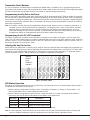
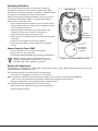
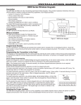
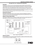
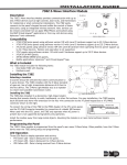
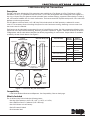
Installation Guide
1100 Series Key Fob Transmitters
Description
The DMP 1100 Series Wireless Key Fob transmitters are available in a Four-Button (1145-4), Two-Button (1145-2),
One‑Button (1145-1), or One‑Button with Prox Patch™ (1145-1-BP) arrangement and are designed to be clipped to a
key ring or lanyard. Key Fob features include a durable water resistant housing, ergonomic button design for ease of
use, and a status feedback LED for visual confirmation. The button status LED responds with specific color-coded LED
displays to indicate system status.
The One‑Button with Prox Patch (1145-1-BP) Key Fob includes a built-in 1306P proximity credential for access
control. This accessory allows controlling the system for such functions as arming, disarming or access control via
the access control credential.
Each button can be individually programmed for one of nine different actions. Key fob programming defaults to the
typical use of the key fob such as Arming, Disarming, and Panic operations. Figure 1 shows the three key fob button
configurations and the table below identifies the default programming for each button. Unique labels are available
to identify the use of each button. See Figure 2.
Top Button
1145-4
4-Button Layout
LED
Side View All Key Fobs
Button
Position
Default
Programming
Top
Arm
Bottom
Disarm
Left
Panic
Right
Arm Area 1 or
Perimeter
Top
Arm
Bottom
Disarm
Top
Panic
1145-1-BP (One-Button) Top
Panic
Key Fob Model
Slot Location
Right
Button
Back
Front
Left
Button
1145-4 (Four-Button)
1145-2 (Two-Button)
1145-1 (One-Button)
Bottom
Button
Front View
1145-1
1-Button Layout
One
(Top)
Button
Connect
Key Ring or
Lanyard Here
1145-2
2-Button Layout
Top
Button
Bottom
Button
Figure 1: 1100 Series Key Fob Transmitters
Compatibility
• 1100 Series Wireless Receivers and Repeater. See Compatibility Chart on back page.
What is Included
The 1100 Series Key Fob includes the following items:
• One key fob transmitter (1145-1-BP, 1145-1, 1145-2, or 1145-4)
• One 1306P Prox Patch™ credential (1145-1-BP only)
• One 3.0V lithium coin cell battery
• Peel-off button ID labels
• Serial number label
Transmitter Serial Number
For your convenience, an additional pre-printed serial number label is included. Prior to programming the device,
record the serial number or place the pre-printed serial number label on the 1100 Series Key Fob Programming Sheet
(LT‑0706) included with the wireless receiver. This number is required during programming.
Programming the Key Fob in the Panel
Refer to the panel programming guide and 1100 Series Key Fob Programming Sheet (LT-0706) as needed. Program the
key fob as a zone in Zone Information during panel programming. At the Serial Number prompt, enter the eight‑digit
serial number, including the leading zero. Continue to program the zone as directed in the panel programming guide.
Should the default button operation need to be changed, the buttons can be reprogrammed to operate as needed in
panel zone programming.
Note: As an option, the key fob may be programmed to be supervised. When a receiver is installed, powered up, or
the panel is reset, the supervision time for transmitters, including key fobs is reset. If the receiver has been
powered down for more than one hour, wireless transmitters may take up to an additional hour to send a
supervision message unless a button is pressed. If programmed, this operation extends battery life. A missing
message may display on the keypad until the key fob sends a supervision message.
Programming the 1145-1-BP Credential
The system requires the credential to be presented to a keypad or card reader to program in the Prox Patch user
code. The 1145-1-BP includes a built-in proximity credential that allows users to perform codeless arming, disarming
and door access. For more information on use of the 1145-1-BP access control credential with your system, refer to
the panel user guide for entering user codes.
Labeling the Key Fob for Use
Attach the key fob transmitter to any key ring or lanyard. Select the peel-off labels that display the programming for
each button and place them onto the corresponding key fob buttons for identification. See Figure 2. For easier label
installation, use a small flat head screwdriver or X-acto knife to select the label and apply it to the proper button
location as shown in Figure 1. Button labels can be changed if programming is changed.
Optional
Small or
Large
Labels are
available.
Figure 2: Button Labels
LED Status Operation
Depending on the programmed action of a key fob button, the Status LED turns on to acknowledge a button press or
to indicate the armed state of the system.
• When the button is programmed for Panic, Panic 2, Emergency, Emergency 2, Output, or Sensor Reset, a 1/2
second Green flash occurs to acknowledge the button press.
• When the button is programmed for Arm, Disarm, Toggle arm/disarm, or Status, the system armed status is
received by the key fob and the LED pulses once as shown in the table below.
LED Color
Duration
Description
Red
2.0 Seconds
All System On
Green
2.0 Seconds
All System Off
Green/Red
2.0 Seconds
System On (Some Areas Armed)
When a button programmed as Unused is pressed, the LED does not operate.
Note: F
or best operation, allow the LED to turn on and then turn off before pressing another button. The key fob
may not complete sending the signal for the button press if another button is pressed too soon.
Digital Monitoring Products
2
1100 Series Key Fob Installation Guide
Replacing the Battery
The 1145 Series Key Fob reports a low battery condition by
automatically testing for a low battery on a daily basis. When
replacement of the key fob battery is necessary, a LOBAT message
will display on the keypad and require a Sensor Reset.
Observe polarity when installing the battery. Use only 3.0V coin
cell batteries, DMP Model CR2032, or the equivalent CR2032
battery from a local retail outlet.
1. Insert a small flat head screwdriver into the slot at the key
fob end opposite the key ring and twist to separate the key
fob front and back sections.
2. Push and slide the old battery out of the holder in the
direction of the arrow to remove it. See Figure 3.
3. Verify the positive side of the battery is up.
4. Slide the new 3.0V Lithium battery into the holder and push
into place.
5. Snap the front and back sections back together.
6. Perform a Sensor Reset to clear LOBAT from the keypad
screen.
Sensor Reset to Clear LOBAT
1. Press 2 and hold for two seconds on the keypad.
2. Enter your user code if required.
3. The keypad displays SENSORS OFF followed by SENSORS ON.
Caution: Properly dispose of used batteries. Do not
recharge, disassemble, heat above 212°F (100°C), or
incinerate. Risk of fire, explosion, and burns.
Key Fob Front
Push Battery
Edge to Slide
Battery Out
Battery
Inside Battery
Compartment
Slot
Insert Battery
with Positive
Side Up
Figure 3: 1100 Series Battery Location
Battery Life Expectancy
Typical battery life expectancy for DMP Model 1100 Series Key Fobs is 2 years. DMP wireless equipment uses two-way
communication to extend battery life.
The following situations can reduce battery life expectancy:
• If a receiver is unplugged, too far away, or not installed.
Note: Transmitters continue to send supervision messages until a receiver returns an acknowledgement.
After an hour the transmitter only attempts a supervision message every 60 minutes.
• Frequent transmissions, such as pressing a button multiple times.
The following situation can extend battery life expectancy:
• Extend transmitter supervision time in panel programming.
• Infrequent button presses.
1100 Series Key Fob Installation Guide
Digital Monitoring Products
3
FCC Information
This device complies with Part 15 of the FCC Rules. Operation is subject to the following two conditions: (1) This
device may not cause harmful interference, and (2) this device must accept any interference received, including
interference that may cause undesired operation.
Changes or modifications made by the user and not expressly approved by the party responsible for compliance could
void the user’s authority to operate the equipment.
Note: This equipment has been tested and found to comply with the limits for a Class B digital device, pursuant
to part 15 of the FCC Rules. These limits are designed to provide reasonable protection against harmful
interference in a residential installation. This equipment generates, uses and can radiate radio frequency
energy and, if not installed and used in accordance with the instructions, may cause harmful interference
to radio communications. However, there is no guarantee that interference will not occur in a particular
installation. If this equipment does cause harmful interference to radio or television reception, which can be
determined by turning the equipment off and on, the user is encouraged to try to correct the interference by
one or more of the following measures:
- Reorient or relocate the receiving antenna.
- Increase the separation between the equipment and receiver.
- Connect the equipment into an outlet on a circuit different from that to which the receiver is connected.
- Consult the dealer or an experienced radio/TV technician for help.
Note: The 1100 Series wireless system is a two-way supervised wireless design. It is compliant with FCC rules as
they pertain to 900 MHz Spread Spectrum devices. In rare instances it has been observed that certain 900 MHz
cordless telephones may occasionally experience a clicking sound on the telephone while in use. If this occurs,
it may be resolved by selecting a different channel on the cordless telephone, or replacing the cordless phone
with a different brand or model of 900 MHz telephone or other cordless telephone.
Compatibility
Battery
Life Expectancy 2 years
Type
3.0V lithium CR2032
See Battery Life Expectancy for full details.
Dimensions
1.98” H x 1.98” W x 0.6” D
Color
Black
Housing Material ABS Plastic
1100X Wireless Receiver Version 101 or higher with
XR100/XR500 Series Version 113 or higher
XR150/XR350/XR550 Series panels
1100XH Wireless Receiver Version 105 or higher with
XR100/XR500 Series Version 113 or higher
XR150/XR350/XR550 Series panels
1100D Wireless Receiver Version 103 or higher with
XT30/XT50 Series Version 102 or higher
1100DI Wireless Receiver Version 105 or higher with
XT30/XT50 Series Version 102 or higher
1100DH Wireless Receiver Version 105 or higher with
XT30/XT50 Series Version 102 or higher
1100R Wireless Repeater
XT50 Series built-in Wireless Receiver
XTL/XTLN/XTLN-WiFi Wireless Control panel
Patents
U. S. Patent No. 7,239,236
Certifications
FCC Part 15 Registration ID CCKPC0098
800-641-4282
INTRUSION • FIRE • ACCESS • NETWORKS
www.dmp.com
2500 North Partnership Boulevard
Designed, Engineered and
Assembled in U.S.A.
Springfield, Missouri 65803-8877
LT-0703 © 2015 Digital Monitoring Products, Inc.
15175
Specifications