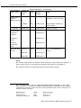
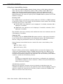
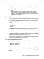
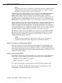
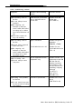
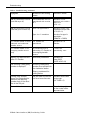
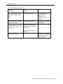
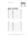
1
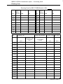
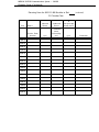
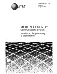
AT&T
®
MERLIN LEGEND
Communications System
Basic Rate Interface
Provisioning Guide and
Planning Forms
Copyright © 1994, AT&T
All Rights Reserved
Printed in U.S.A.
AT&T 555-601-112
Issue 1
October 1994
Notice
Every effort was made to ensure that the information in this book was complete and accurate at the time of
printing, However, information is subject to change,
Security of Your System: Preventing Toll Fraud
As a customer of a new telephone system, you should be aware that there exists an increasing problem of
telephone toll fraud, Telephone toll fraud can occur in many forms, despite the numerous efforts of telephone
companies and telephone equipment manufacturers to control it.
Federal Communications Commission Statement
This equipment has been tested and found to comply with the limits for a Class A digital device, pursuant to Part
15 of the FCC Rules, These limits are designed to provide reasonable protection against harmful interference
when the equipment is operated in a commercial environment, This equipment generates, uses, and can
radiate radio frequency energy and, if not installed and used in accordance with the instruction manual, may
cause harmful interference to radio communications. Operation of this equipment in a residential area is likely to
cause harmful interference, in which case the user will be required to correct the interference at his own
expense.
Trademarks
5ESS, MERLIN, MERLIN LEGEND MLX-10, MLX-10D, MLX-20L, and MLX-28D are registered trademarks of AT&T in the
U.S. and other countries.
Ordering Information
The ordering number for this document is 555-601-112, To order this document, call the AT&T GBCS Publication
Fulfillment Center at 1-800-457-1235, For more information about AT&T documents, refer to the section entitled,
“Related Documents” in “About This Book.” The Pocket Reference, listed in that section, provides full ordering
information for replacement parts, accessories, and other compatible equipment; or, contact your AT&T
representative.
Support Telephone Number
In the continental U.S., AT&T provides a toll-free customer helpline 24 hours a day. Call the AT&T Helpline at
1-800-628-2888 if you need assistance when installing or using your system.
Outside the continental U. S., contact your local AT&T representative,
Warranty
AT&T provides a limited warranty on this product.
Basic Rate Interface (BRI) Provisioning Guide
Contents
About This Guide
■
■
v
v
vi
Intended Audience
Related Documents
Introduction
2
Central Office Provisioning
4
Standard BRI Operation Provisioning
■ Optional Features Provisioning
Calling Party Number/Billing Number
Incoming Calls
Outgoing Calls
CO Transfer
Local Area Signaling System (LASS) Features
Multi-Level Precedence and Preemption (MLPP)
Multi-Line Hunt Group (MLHG)
Dialing Plan
5
7
9
9
9
10
11
12
12
12
System Testing and Verification
14
Background
■ Requirements
■ Testing
■ Verification
14
16
16
19
Troubleshooting
27
Appendix A - Planning Form
A-1
■
■
Basic Rate Interface (BRI) Provisioning Guide iii
About This Guide
This document describes the line and feature parameters that must be
provisioned at the central office for basic connectivity and additional
calling capabilities for the MERLIN LEGEND® Basic Rate Interface (BRI)
system. Also included are the procedures used by system technicians to
verify both the service provisioned on the BRI lines and the proper
functioning of the MERLIN LEGEND BRI system in supporting BRI. A master
copy of the planning form used for the verification process is included as
Appendix A.
Intended Audience
This book is intended for use as a reference by anyone needing such
information, including support personnel, sales representatives, system
managers, and users of the MERLIN LEGEND BRI system. It is also intended
for system technicians who are responsible for system installation,
maintenance and troubleshooting.
Basic Rate Interface (BRI) Provisioning Guide v
Related Documents
Related Documents
In addition to this book, the documents listed below are part of the
documentation set. Within the continental United States, these
documents can be ordered from the AT&T GBCS Publication Fulfillment
Center by calling 1-800-457-1235.
Document
555-601-111
555-601-112
555-620-116
555-601-110
I
Title
System Documents
BRI Supplemental Reference
BRI Provisioning and Planning
Pocket Reference
Telephone User Support
BRI Access Button Quick Reference
vi Basic Rate Interface (BRI) Provisioning Guide
Basic Rate Interface (BRI) Provisioning Guide
This section describes the line and feature parameters that must be provisioned at the
central office for basic connectivity and for additional calling capabilities provided
by optional BRI features.
Introduction
The MERLIN LEGEND® BRI system is designed to operate with 5ESS Generic 8 (or 9)
Custom BRI central office switches. The system presents a U-interface and works with 2
binary. 1 Quarternary (2B1Q) line coded Integrated Services Digital Network (ISDN) BRI
lines.
The service on each BRI line is specified in a User Service Order Profile (USOP), which is
configured on the 5ESS central office at subscription time. The USOP contains
information necessary for the 5ESS to provide service to each station connected to
the system. Each USOP is identified by a Service Profile Identifier (SPID).
Basic Rate Interface (BRI) Provisioning Guide 1
Introduction
When BRI lines are ordered, the following important information used for MERLIN
LEGEND installation is provided by the local telephone company:
■
Directory Number (DN)
Each Digital Subscriber Line (DSL) has two 64-Kbps B-channels capable of
allowing two separate calls to be placed or received at once. For each DSL,
two telephone numbers, also known as DNs, are assigned.
■
Service Profile ID (SPID)
One SPID is provided for each DN ordered, The SPID is generally consists of a
string often digits O through 9. The SPID is required for system programming.
■
Multiline Hunt Group (MLHG) hunt sequence
The MLHG features allows a customer to publish one telephone number with
access to number of lines needed to handle incoming and outgoing call
volumes. If the customer orders the MLHG feature, the DNs will hunt in a specific
sequence. Normally the sequence is linear, starting with the lowest DN. This
information may be used for the following system programming:
— Assigning BRI lines to pools, This ensures that outgoing BRI lines
can be selected in reverse order from expected incoming
call volume.
2 Basic Rate Interface (BRI) Provisioning Guide
Central Office Provisioning
Central Office Provisioning
When a MERLIN LEGEND BRI system is installed, certain line and feature parameters
must be coordinated with the 5ESS central office to ensure proper operation. Refer to
the MERLIN LEGEND Basic Rate Interface Supplemental Reference (555-601-111) for
the required settings on the MERLIN LEGEND BRI system.
The categories of required parameters that must be provisioned at the 5ESS central
office are as follows:
■
Standard BRI operation-~mandatory for basic connectivity and to support
inbound and outbound calling and video configurations.
■
Optional-provide additional calling capabilities
In general, the MERLIN LEGEND BRI system supports circuit-switched service only
(SAP 0). D-channel data service (SAP16) iS not supported and should not be
provisioned.
Basic Rate Interface (BRI) Provisioning Guide 3
Central Office Provisioning
Standard BRI Operation Provisioning
The attributes in the following table must be set as indicated for all MERLIN LEGEND BRI
system installations. These attributes can be found on screens 2.3,4, and 5 of Recent
Change view 23.8.
Table 1. Installation: Standard BRI Operation Mandatory Provisioning
Attribute Name
*
Value
Recent Change
Notes
NT1TYPE
AULC
23,8 Screen 2
Line Coding is 2B1Q
(U interface)
DSL CLS
MP
23.8 Screen 2
Class of Service is
multipoint
MTERM
2
23.8 Screen 2
Maximum number of
terminals on DSL
MAXB CHL
1
23,8 Screen 3
Maximum number of
channels per terminal
ACT USER
Y
23.8 Screen 3
Actual user
CKT LCC
DS1*
23.8 Screen 4
DS1 = Circuit-Switched
Service
TERMTYP
TYPED
23.8 Screen 4
Type ‘D’ terminal being
emulated
The actual name "DS1" for the Line Class Code maybe different depending on the central
office. The name is not relevant for MERLIN LEGEND BRI system provisioning, but the standard
configuration for the Line Class Code used as the parameter for the CKT LCC must be set as
follows for proper operation:
Attribute Name
===========
Class of Service
Terminating Treatment
Value
====
ISDN
INDIV
4 Basic Rate Interface (BRI) Provisioning Guide
Recent Change
==============
4.1 Screen 1
4.1 Screen 1
Central Office Provisioning
Table 1. Installation: Standard BRI Operation Mandatory Provisioning, (continued)
Recent Change
Notes
1
23.8 Screen 4
1 circuit-switched voice
call active**
ANY
23.8 Screen 4
Either B-channel usable for
voice
1
23.8 Screen 4
1 circuit-switched data call
active**
CSD CHL
ANY
23,8 Screen 4
Either B-channel usable for
data
DISPLAY
N
23.8 Screen 4
No display messages to be
sent
CA
1
23.8 Screen 4
First call appearance is at
button 1
CA QTY
2
23.8 Screen 4
2 call appearance per DN
CA PREF
R
23.8 Screen 5
Assert Ringing Line
Preference
AUTO HOLD
N
23.8 Screen 5
Assert ‘Auto Drop’
ONE TOUCH
N
23.8 Screen 5
Defeat ‘One Touch’ feature
SAR QTY
1
23.8 Screen 5
Set a sub-address
reservation to 1
SAR ORIG
Y
23.8 Screen 5
Allocate the reserved CA
for origination
Attribute Name
CSV
CSV CHL
CSD
**
Value
Up to one call active on each BRI line. Each DSL supports two BRI line thus two simultaneous
calls.
Basic Rate Interface (BRI) Provisioning Guide 5
Central Office Provisioning
Optional Features Provisioning
The MERLIN LEGEND BRI system supports several optional BRI features offered by the
5ESS central office. The following features can be provisioned at the customer’s
request and used individually or in combination:
Calling Party Number (CPN)/Billing Number (BN)
CO Transfer
Local Area Signaling Service (LASS) features:
— Automatic Callback
— Automatic Recall
— Customer Originated Trace
Multi-Level Precedence and Preemption (MLPP)
Multi-Line Hunt Group (MLHG)
Dialing Plan
The following table contains attributes and the settings required for proper operation
of the optional feature on the MERLIN LEGEND BRI system.
6 Basic Rate Interface (BRI) Provisioning Guide
Central Office Provisioning
Table 2. Features:
Standard BRI Operation Mandatory Provisioning
Feature Name
Attribute
Name
Value
Recent
Change
Notes
Calling Party
Number
/Billing Number
/CPCPFA
N/A
23.8 Screen 6
Calling Party Number
Preference, Auto Activate
N/A
23.8 Screen 6
Billing Number Preference,
Auto Activate
23.8 Screen 6
Multiway Calling
or
/CPBPFA
CO Transfer
/MWICTIA
LASS Features:
Automatic
Callback
23.8 Screen 6
Automatic
Recall
23,8 Screen 6
Customer
Originated
Trace
23,8 Screen 6
Multi-Line Hunt
Group
CKT LCC
DS2*
23.8 Screen 4
SAR QTY
o
23.8 Screen 5
SAR ORIG
N
23.8 Screen 5
DS2 = Circuit-Switched
Service
NOTE:
The forward slash before an attribute name indicates a “preconstructed" feature. In
some central offices. a preconstructed feature is indicated by an asterisk (*).
The optional features are further described on the following pages.
*
The actual name "DS2" for the Line Class Code maybe different depending on the central
office. The name is not relevant for MERLIN LEGEND BRI system provisioning, but the standard
configuration for the Line Class Code used as the parameter for the CKT LCC must be set as
follows for proper operation:
Attribute Name
----------Class of Service
Value
---ISDN
Recent Change
-- -- -- -- -- -- -- -- -- -- -- -4.1 Screen 1
Terminating Treatment
MLHG
4.1 Screen 1
Basic Rate Interface (BRI) Provisioning Guide 7
Central Office Provisioning
Calling Party Number/Billing Number
The Calling Party Number/Billing Number feature allows an MLX display telephone
user to see the caller’s calling party number (CPN) or billing number (BN) on the
display. The CPN is the number specified by the caller to be delivered for selfidentification. The BN is the number provided by the central office and is used for
billing information. The caller can specify if the CPN/BN should be private and if CPNs
should be screened.
Incoming Calls
The CPN/BN feature is provisioned by setting either the /CPCPFA or /CPBPFA attribute
as indicated in Table 2. For incoming calls, the attribute chosen results in the following
information sent by the central office:
■
/CPCPFA-CPN is the preference and is displayed, if available; otherwise, BN is
displayed, if available
■
/CPBPFA-BN is the preference and is displayed, if available; otherwise, CPN is
displayed, if available
The /CPCPFA is the most commonly used attribute because most customers want the
CPN displayed, if available.
Outgoing Calls
For outgoing calls, the MERLIN LEGEND BRI system sends the calling party information
to the central office to allow display at the destination station. The default setting is
that the calling party information is sent on all calls placed on BRI lines.
Privacy features are available from the central office that control delivery of the
CPN/BN:
■
All-Call Privacy (ACP)
■
Per-Call Privacy (PCP)
The All-Call Privacy (ACP) feature capability allows or prevents the delivery of the
calling party number/billing number (CPN/BN) associated with each BRI line to the
destination station. The All-Call Privacy feature should be ordered for each BRI line
and specified as either activated or not activated. The Per-Call Privacy (PCP) feature
is used to override the All-Call Privacy feature.
NOTE:
It is highly recommended that the same privacy configuration be provisioned
for all BRI lines ordered to reduce customer confusion and prevent difficulties in
future moves and changes.
All-Call Privacy Activated
When the All-Call Privacy feature has been activated at subscription time, the
CPN/BN for the BRI line is not sent to the destination station when the BRI line is used to
place an outside call. Using the Per-Call Privacy feature causes the CPN/BN for the
BRI line to be sent for the next call only.
8 Basic Rate Interface (BRI) Provisioning Guide
Central Office Provisioning
All-Call Privacy Not Activated
If the All-Call Privacy feature has not been activated, the CPN/BN for the BRI line is
sent to the destination station when the BRI line is used to place an outside call. Using
the Per-Call Privacy feature prevents the CPN/BN for the BRI line from being sent for
the next call only,
NOTE:
Different central offices may offer various options and option packages
depending on local needs and regulations. Contact the local operating
company to obtain complete information on options and option packages
available in each central office.
CO Transfer Feature
If the CO Transfer feature is ordered, the parameters must be set as shown in Table 2.
CO Transfer is not tariffed separately and must be ordered as part of the Multiway
Calling (/MWICTIA) package consisting of the following CO features:
■
Hold
■
Transfer
■
Conference
■
Drop
The MERLIN LEGEND BRI system does not support the use of central office-based
features — Conference, Drop, or Hold (except as a sub-function of the CO Transfer
feature). This is because users will most likely use the MERLIN LEGEND equivalents of
these features.
Various options and option packages are available for special operation required by
the customer. For example, options to restrict transfer destinations, to restrict transfer
completion. or to vary the procedure used to transfer a call.
Contact the local operating company to obtain complete information on options
and option packages available in each central office.
Local Area Signaling System (LASS) Features
Three LASS features are supported on the MERLIN LEGEND BRI system and are
optioned on Recent Change 23.8, screen 6:
■
Automatic Callback (AC)
■
Automatic Recall (AR)
■
Customer Originated Trace
LASS features should be used only on Personal Line buttons, Refer to the MERLIN
LEGEND Basic Rate hterface Supplemental Reference (555-601-111) for complete
information on considerations and operation of LASS features on the MERLIN LEGEND
BRI system.
Basic Rate Interface (BRI) Provisioning Guide 9
Central Office Provisioning
NOTE:
Depending on the local central office, LASS features may be available under a
different names. Contact the local operating company to obtain complete
information on feature names in each central office.
Some LASS global parameter settings at the central office may affect the Automatic
Callback and/or the Automatic Recall feature operation. The MAX RNGBK and
RNGBK WAIT options on Form 8.21 indicate the maximum number of ringback
attempts and the time interval (in minutes and seconds) between ringbacks after an
unanswered attempt. MAX RNGBK can be set in the range of 1 to 12 attempts and
RNGBK WAIT can be set in the range of 3 to 12 minutes (in increments of 15 seconds).
These parameters can be used to have the Automatic Callback or Automatic Recall
feature attempt to deliver the callback multiple times at specified time intervals.
Unless these parameters are programmed, the default setting will cause Automatic
Callback or Automatic Recall ringbacks to be attempted only once. If the ringback is
not answered after that one attempt (for example, if the user is on another call), the
Automatic Callback or Automatic Recall feature is canceled for that call.
The maximum setting (12) for MAX RNGBK is recommended for the MERLIN LEGEND
BRI system, However, these parameters are generally global settings at the central
office and the local telephone company may not be willing to change them for
MERLIN LEGEND BRI system customers.
NOTE:
Settings may vary in different central offices. Contact the local telephone
company for information about ranges and recommended settings.
Multi-Level Precedence and Preemption (MLPP)
Numerous options can be set for MLPP. but these options are not addressed in this
document. In general, options are provisioned for MLPP for a MERLIN LEGEND BRI
system in the same manner as those assigned for directly connected terminals. Refer
to the MERLIN LEGEND Basic Rate Interface Supplemental Reference (555-60 1-111 ) for
details on the MLPP feature.
Multi-Line Hunt Group (MLHG)
The following information must be provided to the central office at subscription time
when some or all of the BRI lines are included in a Multi-Line Hunt Group (MLHG):
■
Number of lines included in the MLHG
■
Hunt type-linear or circular
The central office provides a main (starting) number and the line hunting order.
The CKT LCC, SAR QTY, and SAR ORIG attributes must be set differently from the
standard BRI configurations settings as shown in Table 2.
10 Basic Rate Interface (BRI) Provisioning Guide
Central Office Provisioning
Dialing Plan
In general, the MERLIN LEGEND BRI system does not require connection of Centrex
lines. The need for Centrex service is determined by specialized business needs for
services offered by Centrex, or in some areas, local tariffing or availability issues may
require that BRI lines connected to the MERLIN LEGEND BRI system be Centrex-based.
For example, in one geographic area, mandatory Subaddress (SAR) option is
available only as a Centrex feature.
An example of a business need requiring a specialized dialing plan is the customer
who wants an arrangement where branch offices can be dialed using a less-thanseven-digit number. This capability is made possible by ordering Centrex lines and
making use of Centrex groups and Individualized Dialing Plan (IDP).
The cost for Centrex services varies depending on local tariffs.
When an outgoing call is placed on a non-Centrex BRI line, the dialing sequence is
the same as on other types of lines (optional 1 + area code, followed by a seven-digit
number),
When an outgoing call to a destination not included in the Centrex group is placed
on a Centrex BRI line, the above mentioned dialing sequence must be preceded by
a “9. ” Branch offices or other organizations included in the Centrex group can be
reached by dialing an “extension number. ”
Basic Rate Interface (BRI) Provisioning Guide 11
System Testing and Verification
System Testing and Verification
This section contains procedures used by systems technicians to verify both the
service provisioned on the BRI lines and the proper functioning of the MERLIN LEGEND
BRI system in supporting BRI. Refer to the MERLIN LEGEND Communications System
Installation manual (555-620-141) and the MERLIN LEGEND Basic Rate Interface
Supplemental Reference (555-601-111) for complete installation instructions and
cautions.
Background
BRI lines from the 5ESS central office connect to the MERLIN LEGEND BRI system
through the 800 CO-BRI module installed on the carrier. Each module has eight ports.
Each port can be connected a Digital Subscriber Line (DSL) line via a D8W cord. Each
DSL supports two BRI lines, each with its own Directory Number (DN), that is, the
telephone number for the line. Each 800 CO-BRI module can be used to connect 16
BRI lines.
The MERLIN LEGEND BRI system internally maps each BRI line to a system line identified
by a unique line number (801 through 880), Lines can be assigned to stations as
Personal Lines or can be assigned to pools. Each station with a BRI line assigned as a
Personal Line button has full use of BRI features provisioned for the BRI line at the 5ESS
central office.
Figure 1 illustrates the physical connection of a DSL from the 5ESS central office to the
MERLIN LEGEND, the internal mapping of lines, and the assignment of lines to stations.
mm
Station Modules
Ext. 43
Figure 1. Mapping of Lines from the 5ESS Central Office to MERLIN LEGEND Stations
12 Basic Rate Interface (BRI) Provisioning Guide
System Testing and Verification
Requirements
Prior to installation of the system, the systems technician or consultant must acquire
the following information:
■
Letter of Agency from the customer
■
Contact number at the central office for troubleshooting
■
MERLIN LEGEND and MERLIN LEGEND BRI System Planning forms
The following equipment is necessary for testing BRI lines:
■
MERLIN LEGEND BRI system with the BRI Feature module
■
Three MLX display telephones
■
A telephone with existing access to the central office
■
One or more 800 CO-BRI modules (a maximum of five can be installed
depending on the power supply)
■
BRI lines with SPIDs and DNs provided by the 5ESS central office and USOP
configuration parameters
■
A Tektronix Craftek Model CT100 (recommended) for troubleshooting lines
■
ISDN telephone with an NT1 interface
Testing
To ensure ease of programming and minimize human error, it is recommended that
testing for correct operation of the BRI line and the system be performed on the
MERLIN LEGEND BRI system in its default state with minimal system programming. After
completion of testing, the system can be configured to meet customer needs as
indicated by the system planning forms with the assurance that the BRI lines will
function reliably.
Use the following steps as a guideline to install and test the MERLIN LEGEND BRI
system. Refer to the MERLIN LEGEND Communications System Installation manual (555620-141 ) and the MERLIN LEGEND Basic Rate Interface Supplemental Reference (555601-111 ) for complete installation instructions and cautions.
1.
If upgrading an existing MERLIN LEGEND system, backup the current customer
translations on a diskette.
2.
Turn the system off.
3.
Install the 800 CO-BRI modules (maximum of five, three per carrier) in the system
leaving no empty slots before the last module.
4.
Turn the system on.
5.
Wait for the red LED on the processor module to go off.
6.
Frigid start the system,
Basic Rate Interface (BRI) Provisioning Guide 13
System Testing and Verification
7. Wait for the red LED on the processor module to go off. (The red LED on each 800
CO-BRI module should be on indicating no service on each port.
8. Perform diagnostic tests on each module:
■
Internal Ioopback test
■
Board controller test
■
B-channel Ioopback test
a. Put the module out-of-service by busying it out:
(1).
Press Menu ➜ Maintenance.
(2).
Press slot.
(3)0
Enter the slot number of the module.
(4).
press Enter ➜ Busy ➜ Out
➜ Yes.
(5). Wait for the busy-out to complete,
(6).
Press Exit.
b. Execute the tests:
(l).
Press Demand Test ➜ IntLoopback ➜ Test Once.
(2).
Wait for the test to complete.
(3).
If the test passes, press Exit ➜ Exit and continue with the
next test. If the test fails, follow the procedure in step 8d
below to remove the module.
(4).
Press BoardCntrlr ➜ Test Once.
(5).
Wait for the test to complete.
(6).
If the test passes, press Exit ➜ Exit and continue with the
next test. If the test fails, follow the procedure in step 8d
below to remove the module.
(7).
Press BchLoopback.
(8).
Wait for the test to complete.
(9).
If the test passes. press Exit + Exit and continue with the
next test. If the test fails, follow the procedure in step 8d
below to remove the module.
(10).
Press Exit.
c. Put the module back in service:
(1).
Press Restore ➜ Yes.
(2). Wait for the restore to complete.
(3). If more modules require testing. press Exit+ Exit and repeat from step
8a(3) above. When all modules have been tested, press Home.
14 Basic Rate Interface (BRI) Provisioning Guide
System Testing and Verification
d. A module that fails a test should usually be removed. Remove the module from
the module as follows:
(1).
Put the module back in service:
Press Menu ➜ Maintenance ➜ Slot.
Enter the number of the module,
Press Enter ➜ Restore ➜ Yes,
Wait for the restore to complete.
9.
(2).
Turn the system off,
(3).
Remove the module.
(4).
Shift the modules to remove any resulting empty slots
between modules.
(5).
Turn the system on,
(6).
Wait for the red LED on the processor module to go off,
(7).
Continue testing each module.
Plug BRI DSLs into the ports on the 800 CO-BRI modules, starting with the bottom
port on the first module, continuing sequentially toward the top port, Proceed
to the next module, and plug BRI DSLs into the ports in the same order. It is
recommended that you plug in the DSLs sequentially in order of their
respective DNs,
10. Program the SPID for each BRI line. Once the SPID is programmed, the BRI line is
activated. (Press Exit at anytime to leave system programming without
saving the current changes.)
a. Press Menu ➜ SysProgram ➜ Exit ➜ LinesTrunks ➜ More ➜ BRI ➜
ServProfid.
b. Enter the line number of the BRI line.
c. Press Enter.
d. Enter the ten-digit SPID for the BRI line.
e. If more BRI lines require SPID programming, press Next and repeat from step
13d above, When the SPID is programmed for all BRI lines, press Enter ➜
Home.
Basic Rate Interface (BRI) Provisioning Guide 15
System Testing and Verification
Verification
Once installation testing is completed, the serviceability of the BRI lines must be
verified. For this procedure, duplicate one planning form from Appendix A of this
guide for each 800 CO-BRI module installed in the carrier. Since it is unlikely that a test
can continue if a subtest fails, it is very important that you record both the basic
results and unexpected conditions (those that differ from the expected results
described) of each test on the planning form. This will help in troubleshooting should a
BRI line fail a test and further testing cannot be performed, Refer to the
“Troubleshooting” section that follows for information on suggested causes and
corrective actions for lines that fail one or more tests.
Follow these steps to verify each BRI line:
1.
Using the completed “Control Unit Diagram - from System Form 1, write the slot
number for each 800 CO-BRI module in the space provided at the top of the
planning form,
2.
Using the “Log. ID” and “Trunk No. ” columns on System Form 2c, System
Numbering- Trunk Jacks, write the logical IDs and line numbers for each BRI line
connected to an 800 CO-BRI module. “Unequipped” in the “Incoming Trunk Type"
column indicates a port not used at this time.
3.
Using the “Directory Number” and “Service Profile Identifier columns on System
Form 3e, Outs/de Lines— BRI Options, write the Directory Number (DN) and
Service Profile Identifier (SPID) for each BRI line.
4.
Locate the three MLX display telephones to be used for verification. One station
must have a minimum of three blank buttons. One of the buttons must be in the
first ten and is used to program a BRI Access button. The other buttons are used to
assign a pair of BRI lines from the same DSL. This station is referred to as station A in
this procedure.
The other two stations must have one blank button. These stations are referred to
as stations B and C in this procedure.
In addition, locate a fourth telephone with access to the central office. Any type
of telephone can be used. This station is referred to as station D in this procedure.
5.
Set up stations B and C by assigning the first two BRI lines starting from the last DSL
that can be used to place and receive calls:
a. Assign a line from the last DSL to station B:
(1).
Press Menu ➜ SysProgram ➜ Exit ➜ Extensions ➜
LinesTrunks.
(2).
Enter the extension of the station.
(3).
Press Enter.
(4).
Press the range corresponding to the logical ID for the BRI
line being assigned to the button or select Entry Mode.
16 Basic Rate Interface (BRI) Provisioning Guide
System Testing and Verification
(5).
Press the button corresponding to the logical ID to turn on
the LED (if assigning a line) or turn off the LED
(if removing a line), or if you selected Entry Mode, enter the line number.
(6).
Repeat from 5a(4) to assign more lines to the station or from
5a(2) to assign lines to another station or press Enter. When
programming is complete, press Home.
b. Verify that the lines were assigned to the buttons:
(1).
Exit ADMIN.
(2).
Press Inspect to enter the inspect mode.
(3).
Press the button on which the line was assigned:
■ If
a line is assigned to the button, the “Line 8XX - 1“ is
shown on the display (8XX is the line number for the BRI line
assigned to the button).
■
(3).
If the button is a BRI Access button, the “BRI Access” is
shown on the display.
Press Home to exit the inspect mode.
c. Place a test call from station B to station D:
(1).
Pre-select the button for the line,
—
The red LED next to the button is steadily lit.
If not, check that this line has been assigned to the button using the
procedure in steps 5a and 5b above.
(2).
Lift the receiver.
—
The red and green LEDs next to the button are steadily lit and you
hear dial tone.
If not, (the red LED goes off), and this is the first call attempt, verify
that the SPID is entered correctly for the line and try the call again
after about a minute. If the call fails again, unplug and replug the
corresponding DSL and try the call again after about a minute. If this
final call fails once again, write “n” in the “Outgoing Call” column of
the planning form and write the type of tone, if any, that you hear at
the calling and destination stations in the “Comments” column.
Basic Rate Interface (BRI) Provisioning Guide 17
System Testing and Verification
(3).
Dial the directory number for the BRI line assigned to the
station you are calling, If Centrex lines are connected dial a
“9" before the telephone number.
— Dial tone goes off after the first digit is dialed.
— After the last digit has been dialed, you hear ringback at the calling
station and ringing at the station being called.
If either is missing, verify that the dialed digits are correct for the BRI
line assigned to the button at the destination station, Redial if
necessary, If the test fails again, write “n” in the “Outgoing Call”
column of the planning form and write the type of tone, if any, that
you hear at the calling and destination stations in the “Comments”
column of the planning form.
(4).
Answer the call at the destination station,
(5).
Verify connectivity,
d. Using the procedure in 5C above, place a test call from station D to station B.
When you answer the call on station B, check for station D’s calling party
information on the station B’s display. Record the results of the test on the
planning form. If the test fails, assign another line to station B and repeat the
procedure in step 5 C above.
e. Using the procedure in 5C above, place a test call from station D to station C.
When you answer the call on station C, check for station D’s calling party
information on the station C’s display. Record the results of the test on the
planning form, If the test fails, assign another line to station C and repeat the
procedure in step 5 C above,
NOTE:
Calling Party Number/Billing Number (CPN/BN) information may not be sent or
displayed if All Call Privacy is activated.
6. Program the BRI Access button on station A:
a. Press Menu ➜ SysProgram ➜ Exit ➜ More ➜ Cntr-Prg ➜ Program Ext.
b. Enter the station’s extension.
C. Press Enter ➜ Start,
d. Select a blank button within the first ten buttons,
e. Press ListFeature ➜ BRIAccess ➜ Home.
f. Verify that the BRI Access button has been programmed using the Inspect
procedure in step 5b above,
g. Press Home,
7. Select the number of sequential pairs (part of the same DSL) of BRI lines
corresponding to the number of blank buttons on station A, Remember to skip the
lines assigned to stations B and C. Assign the BRI lines to buttons on station A using
the procedure in step 5a and verify button assignment using the procedure in
step 5b above.
18 Basic Rate Interface (BRI) Provisioning Guide
System Testing and Verification
8. Test an outgoing call by placing a call from station A to station B on line 1 of a
DSL:
(1).
Pre-select the button on station A for the line.
—
The red LED next to the button is steadily lit,
If not, check that this line has been assigned to the button using the
procedure instep 5b above.
(2) 0
Lift the receiver.
—
The red and green LEDs next to the button are steadily lit and you
hear dial tone.
If not (the red LED goes off), and this is the first call attempt, verify
whether the SPID is entered correctly for the line and try the call
again after about a minute. If the call fails again, unplug and replug
the corresponding DSL and try the call again after about a minute, If
this final call fails once more, write “n” in the “Outgoing Call” column
of the planning form and write the type of tone, if any that you hear
at stations A and B in the “Comments” column.
(3).
Dial the directory number for the BRI line assigned to the
button on station B. If Centrex lines are connected dial a “9”
before the telephone number.
— Dial tone goes off after the first digit is dialed.
—
After the last digit has been dialed, you hear ringback at station A
and ringing at station B.
If either is missing, verify that the dialed digits are correct for the BRI
line assigned to the button at station B. Redial if necessary, If the test
fails again, write “n” in the “Outgoing Call” column of the planning
form and write the type of tone, if any, that you hear at station A
and/or station Bin the “Comments” column of the planning form.
— Station A’s calling party information is shown on station B
If incomplete or incorrect information is shown, describe the results in
the “Comments” column of the planning form.
(4).
Answer the call at station B.
(5).
Verify connectivity.
(6).
Hang up at station A.
—
The green LED on station A is off.
/f not, select the line and lift the receiver to determine if the call has
been disconnected. If the call is still connected, hangup again. If
the test fails again, write “n” in the “Outbound Disc” of the planning
form. Record the number of tries to disconnect the call in the
“Comments” column of the planning form.
(7).
Hang up at station B.
—
The green LED on station A is still off.
Basic Rate Interface (BRI) Provisioning Guide 19
System Testing and Verification
9.
Perform Test 1 for an incoming call by placing a call from station B to station A on
a BRI line:
(1).
Dial the directory number for the BRI line assigned to the
button on station A. If Centrex lines are connected dial a “9”
before the telephone number.
— Dial tone goes off after the first digit is dialed.
— Station A rings and the green LED next to the button on station A is
flashing,
If either is missing, verify that the dialed digits are correct for the BRI
line assigned to the button at station A. Redial if necessary, If the test
fails again, write “n” in the “Incoming Call Test 1” column of the
planning form and describe the failure in the “Comments” column,
Be sure to record what type of tone/signal you received (busy,
reorder, ringback, etc.).
— Station B’s calling party information is shown on station A
If incomplete or incorrect information is shown, describe the results in
the “Comments” column of the planning form,
(2).
Answer the call at station A.
— The green LED on station A is steadily lit
(3).
Verify connectivity,
(4).
Hang up at station B.
— The green LED on station A is off after a few moments,
If not, write “n” in the “Incoming Call Test 1” column of the planning
form,
(5).
Hang up at station A.
— The green LED on station A is still off,
10. If a line on station A fails the incoming call test, perform Test 2 on that line for an
incoming call using the instructions in step 8 above, This test determines if the first
outgoing call attempt is successful on the line failing Test 1 for an incoming call,
If the line fails, write “n” in Incoming Call Test 2 column
20 Basic Rate Interface (BRI) Provisioning Guide
System Testing and Verification
11. If the line failed both incoming call Test 1 and Test 2, perform Test 3 to determine if
the calling party hears a busy tone when the line is busy:
(1).
Place a call from station B to station A on the BRI line failing both tests.
Station A does not ring on this line.
—
You hear ringback at Station B.
(2).
Place a call on this line from station A to station B.
(3).
Allow the call to ring at station B.
(4),
Place a call to this line from station C to station A.
—
You hear a busy tone on station C.
If not, write “n” in the “Incoming Call Test 3” column and write “no
busy tone when line is busy” and the type of tone you hear at station
C in the “Comments” column of the planning form.
Repeat steps 8 and 9 for all other BRI lines on station A. If the line fails Test 1, repeat
step 10. If a line fails both Test 1 and Test 2, repeat step 11.
12. Test two active calls on a DSL. (This test is valid only if outgoing calls can be
placed from both lines of a DSL.)
a. Place a call from line 1 on station A to station B. Answer the call at station B.
b. Press Hold to put the call on local hold.
— The green LED on station A is fluttering.
c. Place a call on line 2 on station A to station C. Answer the call at station C.
If the test fails, write “n” in the “2 Active Calls” column of the planning form.
d. Hang upon station A to disconnect the call.
e. Retrieve the first call on station A by selecting the button and lifting the receiver.
— The green LED for the first call is steadily lit.
— The green LED for the second call is off.
f.
Hang up at all stations.
a. Repeat this test for all other BRI lines on station A.
Basic Rate Interface (BRI) Provisioning Guide 21
System Testing and Verification
13. Test One-Touch provisioning. (This test is valid only if a line can receive incoming
calls.)
a. Pre-select line 1 on station A and lift the receiver (go off-hook) and then hang
up.
b. Place a call from station B to line 1 on station A.
c. Allow the call to ring at station A but do not answer the call.
d. Hang up at station B.
e. Place another call from station B to line 1 on station A.
You can hear ringback on station B and ringing at station A.
If you hear a busy signal at station B and station A does not ring, write “n” in
the “One Touch” column of the planning form and record the
audio results in the “Comments” column,
f.
Repeat this test for all other BRI lines on station A.
14. Test CO Transfer. (This test is valid only if calls can be placed and received from
the line, and if service is subscribed from the local central office.)
a. Place a call from station B to line 1 on station A. Answer the call at station A.
The transfer source is an incoming call to station A.
b. Press Transfer.
— The green LED on station A is fluttering.
c. Press the BRI Access button,
— The red and green LEDs next to the BRI Access button are steadily lit and
you hear dial tone.
If the test fails, write “Inactive” in the “BRI Acc” column on the planning form
and describe the status of the LEDs.
d. Dial the digits for station C’s DN.
— You hear ringback at station A and ringing at station C.
e. Answer the call at station C.
f.
Press Transfer on station A.
— Stations B and C are connected.
If not, the transfer was not completed, Write “n” in the “Inbound Source”
column. Check that station A is still connected to station C. Then reconnect
to station B by selecting the button next to the fluttering green LED, Check
that station A is now disconnected from station C (the green LED is off) and
connected to station B (the green LED is on).
— Station A is disconnected from both B and C. The green LEDs next to the BRI
Access button and next to the button used to call station B are off.
If not, write “n” in the “A Disconnected from B and C“ column of the
planning form,
22 Basic Rate Interface (BRI) Provisioning Guide
System Testing and Verification
9. Repeat this test for the same line by placing a call from that line on station A to
station B. The transfer source is an outbound call.
If the test fails, write “n” in the “Outbound Source” column of the planning form.
h. Repeat steps 13a through 13g for all other BRI lines on station A.
14. When all lines assigned to station A are tested and more BRI lines are untested,
repeat step 7 above and remove the BRI lines from station A and assign the
untested lines. When all lines are tested, remove the lines from stations B and C
and assign any of the tested lines to those stations then assign the untested lines
from stations B and C to station A. Repeat the above tests for the remaining pairs.
Basic Rate Interface (BRI) Provisioning Guide 23
Troubleshooting
Troubleshooting
Use the information in the following table to take corrective action for any problems
encountered during testing and verification. The information shown in brackets in the
Corrective Actions column is the attribute setting in the central office using Screens 2,
3,4, or 5 of Recent Change view 23.8. Contact the central office representatives for
more information on programming using these screens.
Table 3. Troubleshooting
Symptoms
Possible CO Causes
Corrective Actions
■
No outgoing calls on the
line
Incorrect SPID provided by
the CO
Obtain correct SPID
from the CO
■
No incoming calls on
the line
Point-to-point service (if
the other line cannot
receive incoming calls)
Provision for
multipoint service
(DSL CLS = MP)
Either this line or the other
line on this DSL is not an
active user
Provision both lines
with active user
(ACT USER = Y)
First virtual call
appearance is not at
button 1
Provision first virtual
call appearance at
button 1 (CA= 1)
Packet-switched service
on both B-channels (farend hears reorder tone)
Provision circuitswitched service on
both B-channels
Point-to-point service
Provision for
multipoint service
(DSL CLS = MP)
Only one B-channel
usable for voice. This
provisioning requires pointto-point service
Provision either Bchannel usable for
voice
(CSV CHL = ANY)
■
No incoming calls on
the line
■
Far-end hears ringback
when line is idle
■
First outgoing call
attempt on that line
unsuccessful after failed
incoming call on that
line when it is idle
■
Other line cannot do
any call handling
24 Basic Rate Interface (BRI) Provisioning Guide
Troubleshooting
Table 3. Troubleshooting, continued
Symptoms
No incoming calls on
the line
■ Far end always hears
ringback
■
■
First outgoing call
attempt on that line
unsuccessful after failed
incoming call on either
line of that DSL when it is
idle
■
Other line cannot do
any call handling
■
No incoming calls on
the line
■
Far-end hears ringback
when line is idle
■
First outgoing call
attempt on that line
unsuccessful after failed
incoming call on that
line when it is idle
■
No incoming calls
■
Far-end always hears
busy tone
■
Incoming calls possible
on the line
■
Far end hears busy tone
on the second incoming
call attempt
Possible CO Provisioning
Causes
Corrective Actions
Either this line or the other
line on this DSL is not an
active user
Provision lines with
active user
(ACT USER = Y)
Type A emulation
Provision for type D
emulation
(TERMTYP = TYPED)
Circuit-switched voice is 2
Provision for one
circuit-switched voice
(CSV = 1)
All call appearances are
origination only
Provision for two call
appearances per DN
with the first one
allowing incoming
and outgoing calls
and the second one
permitting outgoing
calls only
(CA QTY = 2,
SAR QTY=l,
SAR ORIG = Y)
One-touch provisioned
Provision for no one
touch
(ONE TOUCH = N)
Basic Rate Interface (BRI) Provisioning Guide 25
Troubleshooting
Table 3. Troubleshooting, continued
Symptoms
Possible CO Provisioning
Corrective Actions
Causes
BRI Access button inactive
(red LED stays off)
Circuit-switched voice is
provisioned with a value
of 2
Provision circuitswitched voice with a
value of 1
(CSV = 1)
BRI Access button inactive
(red LED goes on then off)
One call appearance
Provision for two call
appearances per DN
(CA QTY = 2)
Type A or C emulation
Provision for type D
emulation
(TERMTYP = TYPED)
CO Transfer failure on both
inbound and outbound
transfer source
CO Transfer not
provisioned
Provision for CO
Transfer
CO Transfer failure on an
outgoing transfer source
only
A provisioning error is
preventing CO Transfer of
Correct the
provisioning error
Station not disconnected
after CO Transfer
Auto-Hold provisioned
No incoming calling party
number is displayed
Incoming calling party
number is not provision for
the destination station
an outgoing transfer
source
Provision for
Auto-DROP
(AUTO HOLD = N)
Privacy provisioned for
calling station
Calling party number
shown on the destination
station is the directory
number that of the other
line in the DSL pair
The line used to make the
call is not an active user
None of the above
26 Basic Rate Interface (BRI) Provisioning Guide
Provision this line with
active user
(ACT USER = Y)
Describe the problem
to the central office
representative
Troubleshooting
Table 3. Troubleshooting, continued
.
Symptoms
Possible CO Provisioning
Causes
Corrective Actions
CO Transfer failure on an
outbound transfer source
only
Provisioning problem
A provisioning error is
preventing CO
Transfer of an
outbound transfer
source
Station not disconnected
after CO Transfer
Auto-Hold provisioned
Auto-Drop should be
provisioned
No incoming calling party
number shown when call
placed from station A to
station B
Incoming calling party
number not provisioned
for station A
Privacy provisioned for
station B
None of the above
Describe the problem
to the central office
representative
Basic Rate Interface (BRI) Provisioning Guide 27
Planning Form
This appendix contains a master copy of the planning form you need to
verify serviceability and feature operation of BRI lines connected to the
system.
Duplicate the master and work on the copy.
A-1
MERLIN LEGEND Communications System — Provisioning Guide
Planning Form
Planning Form for 800 CO-BRI Module in Slot
Port
Logical
lD/Line
Number
SPID
DN
Port
1
5
1
5
2
6
2
6
3
7
3
7
4
8
4
8
Port
Outgoing Call
(y/n)
Logical
lD/Line
Number
SPID
Calling Party Number
Comments (tone,
connectivity,
etc.)
(y/n/number)
(A->B)
DN
2 Active Calls One Touch
(y/n)
(y/n)
1 (DN 1)
1 (DN 2)
2 (DN 1)
2 (DN 2)
3 (DN 1)
3 (DN 2)
4 (DN 1)
4 (DN 2)
5 (DN 1)
5 (DN 2)
6 (DN 1)
6 (DN 2)
7 (DN 1)
7 (DN 2)
8 (DN 1)
8 (DN 2)
Planning Form 1
MERLIN LEGEND Communications System — CO-BRI
Planning Form (Continued)
Planning Form for 800 CO-BRI Module in Slot
(continued)
Incoming Call Tests
Port
Calling Party
Number
(y/n/number)
Incoming Call Test 1
(y/n)
Comments (tone,
connectivity. etc.)
Incoming
Call Test 2
(y/n)
Incoming
Call Test 3
(y/n)
1 (DN 1)
1 (DN 2)
2 (DN 1)
2 (DN 2)
3 (DN 1)
3 (DN 2)
4 (DN 1)
4 (DN 2)
5 (DN 1)
5 (DN 2)
6 (DN 1)
6 (DN 2)
7 (DN 1)
7 (DN 2)
8 (DN 1)
8 (DN 2)
Planning Form 2
MERLIN LEGEND Communications System — CO-BRI
Planning Form (Continued)
Planning Form for 800 CO-BRI Module in Slot
(continued)
CO Transfer Test
Port
BRI Acc
Inbound
Source
Outbound
Source
A
Disconnected
from B and C
Comments
(Active, Flash,
Inactive)
1 (DN 1)
1 (DN 2)
2 (DN 1)
2 (DN 2)
3 (DN 1)
3 (DN 2)
4 (DN 1)
4 (DN 2)
5 (DN 1)
5 (DN 2)
5 (DN 1)
5 (DN 2)
7 (DN 1)
7 (DN 2)
8 (DN 1)
8 (DN 2)
(y/n)
(tone,
connectivity,
etc.)
(y/n)
Comments
555-601-112
October 1994
Graphics © AT&T 1988