1
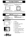
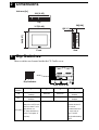
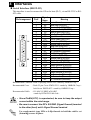
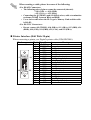
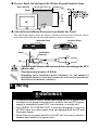
Essential Safety Precautions WARNINGS System Design • Do not create GP touch panel switches that could possibly endanger the safety of equipment and personnel. Damage to the GP, its I/O unit(s), cable(s), and other related equipment can cause an output signal to remain continuously ON or OFF and possibly cause a major accident. Therefore, design all monitoring circuits using limit switches, etc. to etect incorrect device movement. To prevent accidents related to incorrect signal output or operation, de-sign all switches used to control vital machine operations so they are operated via a separate control system. • Do not create switches used to control machine safety operations, such as an emergency stop switch, as a GP touch screen icon. Be sure to install these switches as separate hardware switches, otherwise severe bodily injury or equipment damage can occur. • Do not use the GP unit as a warning device for critical alarms that can cause serious operator injury, machine damage or production stoppage. Critical alarm indicators and their control/ activator units must be designed using stand-alone hardware and/or mechanical interlocks. • Please design your system so that equipment will not malfunction due to a communication fault between the GP and its host controller. This is to prevent any possibility of bodily injury or material damage. • The GP is not appropriate for use with aircraft control devices, aerospace equipment, central trunk data transmission (communication) devices, nuclear power control devices, or medical life support equipment, due to these devices’ inherent requirements of extremely high levels of safety and reliability. • When using the GP with transportation vehicles (trains, cars and ships), disaster and crime prevention devices, various types of safety equipment, non-life support related medical devices, etc. redundant and/or failsafe system designs should be used to ensure the proper degree of reliability and safety. • After the GP’s backlight burns out, unlike the GP’s “Standby Mode”, the touch panel is still active. If the operator fails to notice that the backlight is burned out and touches the panel, a potentially dangerous machine miss-operation can occur. Therefore, do not use GP touch switches for the control of any equipment safety mechanisms, such as Emergency Stop switches, etc. that protect humans and equipment from injury and damage. If your GP's backlight suddenly turns OFF, use the following steps to determine if the backlight is actually burned out. 1) If your GP is not set to "Standby Mode" and the screen has gone blank, your backlight is burned out. 2) Or, if your GP is set to Standby Mode, but touching the screen does not cause the display to reappear, your backlight is burned out. Also, to prevent accidental machine miss-operation, Digital suggests you use the GP’s built-in “USE TOUCH PANEL AFTER BACKLIGHT BURNOUT” feature, that will automatically detect a burnout and disable the touch screen. Installation • High voltage runs through the GP. Except for replacing the backlight, never disassemble the GP, otherwise an electric shock can occur. • Do not modify the GP unit. Doing so may cause a fire or an electric shock. • Do not use the GP in an environment where flammable gasses are present, since operating the GP may cause an explosion. Wiring • To prevent an electric shock, be sure to confirm that the GP's power cord is not connected to the main power when connecting any cords, cables or lines to the GP. • Be sure to replace the GP's plastic terminal block cover after wiring is completed, since operating the GP without the cover may lead to an electric shock • Do not use power beyond the GP's specified voltage range. Doing so may cause a fire or an electric shock. Maintenance • The GP uses a lithium battery for backing up its internal clock data. If the battery is incorrectly replaced, the battery may explode. To prevent this, please do not replace the battery yourself. When the battery needs to be replaced, please contact your local GP distributor. CAUTIONS Installation • Be sure to securely connect all cable connectors to the GP. A loose connection may cause incorrect input or output. Wiring • Ground the GP's FG line separately from other units’ FG lines. Putting these FG lines too close may cause an electric shock or unit malfunction. Be sure to use a grounding resistance of 100W or less and a 2mm2 or thicker wire, or your country’s applicable standard. • Correctly wire the GP, be sure that the rated voltage and terminal layout are within the designated range. If the voltage supplied differs from the rated voltage, or incorrect wiring or grounding is performed, it may cause a fire or unit malfunction. • Use only the designated torque to tighten the GP's terminal block screws. If these screws are not tightened firmly, it may cause a short-circuit, fire, or GP malfunction. • Be careful that metal filings and wiring debris do not fall inside the GP, since they can cause a fire, GP malfunction, or incorrect operation. Maintenance • The liquid crystal panel contains a powerful irritant and if for any reason the panel is damaged and this liquid contacts any part of your body, be sure to wash that area with running water for 15 minutes. If any of this liquid enters your eye, flush your eye for 15 minutes with running water and contact a physician. • Prior to inserting or removing a CF Card, be sure to turn the GP’s CF Card ACCESS switch OFF and to confirm that the ACCESS lamp is not lit. If you do not, CF Card internal data may be damaged or lost. • While a CF Card is being accessed, NEVER turn OFF or reset the GP, or insert or remove the CF Card. Prior to performing these operations, create and use a special GP application screen that will prevent access to the CF Card. Unit Disposal • When this unit is disposed of, it should be done so according to your country's regulations for similar types of industrial waste. General Safety Precautions • Do not strike the touch panel with a hard or pointed object, or press on the touch panel with too much force, since it may damage the touch panel or the display. • Do not install the GP where the ambient temperature can exceed the allowed range. Doing so may cause the GP to malfunction or shorten its operation life. • Do not restrict or limit the GP’s naturally occurring rear-face ventilation, or storing or using the GP in an environment that is too hot. • Do not use this unit in areas where large, sudden temperature changes can occur. These changes can cause condensation to form inside the unit, possibly causing the unit to malfunction. • Do not allow water, liquids, metal or charged particles to enter inside the GP’s case, since they can cause either a GP malfunction or an electrical shock. • Do not use or store the GP in direct sunlight, or in excessively dusty or dirty environments. • Do not store or use the unit where strong jolting or excessive vibration can occur. • Do not store or use the GP where chemicals (such as organic solvents, etc.) and acids can evaporate, or where chemicals and acids are present in the air. Corrosive chemicals: Acids, alkalines, liquids containing salt Flammable chemicals: Organic Solvents • Do not use paint thinner or organic solvents to clean the GP. • Do not store or operate the LCD display in areas receiving direct sunlight, since the sun's UV rays may cause the LCD display’s quality to deteriorate. • Storing this unit in areas at a temperature lower than is recommended in this manual’s specifications may cause the LCD display’s liquid to congeal, which may damage the panel. Conversely, if the storage area’s temperature becomes higher than the allowed level, the LCD’s liquid will become isotropic, causing irreversible damage to the LCD. Therefore, be sure to store the panel only in areas where temperatures are within those specified in this manual. • After turning the GP OFF, be sure to wait a few seconds before turning it ON again. If the GP started too soon, it may not start up correctly. • Due to the possibility of unexpected accidents, be sure to back up the GP’s screen data regularly. Package Contents The following items are included in the GP's package. Before using the GP, please confirm that all items listed here are present. Installation Guide (1) GP Unit (1) <This Guide> (GP2501-TC11/GP2501-SC11) Installation Guide Installation Fasteners (4) Installation Gasket (1) This unit has been carefully packed, with special attention to quality. However, should you find anything damaged or missing, please contact your local GP distributor immediately. Options GP2501 Series User Manual (Sold Separately) Screw Lock Terminal Block (GPL-AXCN01) (Made by Digital) Cables Screen editor software, etc. Maintenance Parts 1 Part Names A,B C E D F H J G I K L A : Display B : Touch Panel C : Status LED D : Power Input Terminal Block E : Expansion Unit I/F F : CF Card Cover G : CF Card Access LED H : CF Card I/F I : Serial Interface (HOST-I/F 25-pin) J : Printer I/F (Half Pitch 20-pin) K : Auxiliary Input/Output Interface L : Tool Connector Connects a Data Transfer Cable or bar code reader 2 Dimensions Unit:mm [in] 301[11.85] Top 58[2.28] 317[12.48] 227[8.94] 243[9.57] 8[0.31] Front Side 3 Dip Switches These switches are located inside the CF Card's cover. Dip Switches Rear View of GP DIP Sw itch 1 2 3 Startup from CF Card is Reserved Reserved enabled. Startup from CF Card is OFF disabled. Designates if forced Keep these switches OFF startup from a CF Card's M emory Loader T ool is perform ed or not. Description (CF Card with M em ory Loader T ool system is required.) ON 4 CF card cover sensor disabled. CF card cover sensor disabled. When this DIP switch is turned ON, the Cf card can be accessed even if the CF card cover is open. T his DIP switch's initial setting is OFF. 4 Interfaces Serial Interface (HOST-I/F) This interface is used to connect the GP to the host (PLC), via an RS-232C or RS422 cable. Pin Arrangement 1 14 13 25 Pin # 1 2 3 4 5 6 7 8 9 10 11 12 13 14 15 16 17 18 19 20 21 22 23 24 25 Signal Name FG SD RD RS CS DR SG CD TRMX RDA SDA NC NC VCC SDB RDB RI CSB ERB ER CSA ERA NC NC NC Meaning Frame Ground Send Data (RS-232C) Receive Data (RS-232C) Request to Send (RS-232C) Clear to Send (RS-232C) Data Set Ready (RS-232C) Signal Ground Carrier Detect (RS-232C) Termination (RS-422) Receive Data A (RS-422) Send Data A (RS-422) No Connection(Reserved) No Connection(Reserved) 5V±5% Output 0.25A Send Data B (RS-422) Receive Data B (RS-422) Ring Indicate (RS-232C) Clear to Send B (RS-422) Enable Receive B (RS-422) Enable Receive (RS-232C) Clear to Send A (RS-422) Enable Receive A (RS-422) No Connection(Reserved) No Connection(Reserved) No Connection(Reserved) Recommended Connector : Dsub 25 pin plug XM2A-2501 <made by OMRON Corp.> Recommended Cover : Dsub 25 pin Cover XM2S-2511 <made by OMRON Corp.> Jack Screw XM2Z-0071 <made by OMRON Corp.> Recommended Cable : CO-MA-VV-SB5P x 28AWG <made by HITACHI Cable Ltd.> • Since Pin#14(VCC) is unprotected, be sure to keep the output current within the rated range. • Be sure to connect the GP's SG/GND (Signal Ground) terminal to the other (host) unit's Signal Ground terminal. Use rough metric type M2.6 x 0.45p threads to hold the cable’s set (fastening) screws in place. When creating a cable, please be aware of the following: <For RS-422 Connectors> • The following pairs of pin no.s must be connected (shorted). ...#18 (CSB) <-> #19 (ERB) ...#21 (CSA) <-> #22 (ERA) • Connecting the #9 (TRMX) and #10 (RDA) wires, adds a termination Ω between RDA and RDB. resistance of 100Ω • Use a 4-wire cable when the PLC type is Memory Link and the cable is RS-422. <For RS-232C Connectors> • Do not connect #9 (TRMX), #10 (RDA), #11 (SDA), #15 (SDB), #16 (RDB), #18 (CSB), #19 (ERB), #21 (CSA), and #22 (ERA). Printer Interface (Half Pitch 20-pin) When connecting a printer, use Digital's printer cable (PSM-PRCB00). Pin Arrangement 1 11 10 20 Pin # 1 2 3 4 5 6 7 8 9 10 11 12 13 14 15 16 17 18 19 20 Signal Name GND RESERVED PDB5 PDB4 PDB3 GND SLCT PDB0 PSTB BUSY PDB7 PDB6 GND ERROR GND PDB2 PDB1 PE INIT GND Meaning Ground Reserved Data Signal Data Signal Data Signal Ground Select Condition(Input) Data Signal Strobe Signal(Output) Busy Signal(Input) Data Signal Data Signal Ground Printer Error(Input) Ground Data Signal Data Signal Paper End Initialize Signal(Output) Ground Auxiliary Input/Output Interface (12 pin) This interface performs external reset, alarm output, and buzzer output. Pin Arrangement I/F Pin No. Signal Name Meaning 1 AUXCOM External Reset Common External Reset 2 AUXRESET External Reset Input 3 RUN Online 1 4 ALARM System Alarm Output 5 OUTCP 24VDC AUX 6 BUZZ External Buzzer Output 7 Reserved Reserved 8 OUTCN 0V 9 Reserved Reserved 12 10 Reserved Reserved 11 Reserved Reserved 12 Reserved Reserved • Using the AUX Input/Output I/F requires the separately sold Screw Lock Terminal Block (GPL-AXCN01). CF Card Interface This slot accepts a CF Card. Expansion Unit Interface This interface is used to connect an expansion unit that can transmit data over a Fieldbus or similar type of network. 5 Installation Confirm the Installation Gasket's Positioning It is strongly recommended that you use the gasket. It absorbs vibration in addition to repelling water. Place the GP on a level surface with the display panel facing downward. Check that the GP’s installation gasket is seated securely into the gasket’s groove, which runs around the perimeter of the panel’s frame. • Before installing the GP into a cabinet or panel, check that the installation gasket is securely attached to the unit. • Be sure the gasket's seam is not inserted into any of the unit's corners, only in the straight sections of the groove. Inserting it into a corner may lead to its eventually tearing. • A gasket which has been used for a long period of time may have scratches or dirt on it, and could have lost much of its dust and drip resistance. Be sure to change the gasket periodically (or when scratches or dirt become visible). Rear face Gasket Create a Panel Cut and insert the GP into the panel from the front Unit: mm [in] 301.5 +10 [11.87 +0.040 ] under 4-R3 GP [8.96 +0.040] 227.5 +10 Panel Attach the Installation Fasteners from Inside the Panel The following figures show the four(4) fastener insertion slot locations. Insert each fastener's hook into the slot and tighten it with a screwdriver. Insertion Slots Top Panel Insertion Slots Bottom Installation fastener GP • Tightening the screws with too much force can damage the GP's plastic case. • The necessary torque is 0.5 N•m. • Depending on the installation panel's thickness, etc., the number of installation fasteners used may need to be increased to provide the desired level of moisture resistance. 6 Wiring WARNINGS • To avoid an electric shock, when connecting the GP's power cord terminals to the power terminal block, confirm that the GP's power supply is completely turned OFF, via a breaker, or similar unit. • The GP2501-TC11/GP2501-SC11 units are designed to use only AC100V input. Any other power level can damage both the GP and the power supply. • Since there is no power switch on the GP unit, be sure to attach a breaker-type switch to its power cord. • When the FG terminal is connected, be sure the wire is grounded. Not grounding the GP unit will result in excess noise and vibration. • Wherever possible, use thick wires (max. 2 mm2) for power terminals, and twist the wire ends before attaching the ring terminals. • Be sure to use the following size ring terminals.*1 • To avoid a short caused by loose ring terminals, be sure to use ring terminals with an insulating sleeve. Rear of GP Ring Terminals*1 Power Input Terminal Block *1 Suggested Ring Terminal : V2-MS3 (made by JST) Connecting the GP Power Cord When connecting the power cord, be sure to follow the procedures given below. 1. Confirm that the GP's Power Cord is unplugged from the power supply. 2. Use a screwdriver to remove the Power Input Terminal Block's clear plastic cover. 3. Unscrew the screws from the middle three (3) terminals, align the Ring Terminals and re-attach the screws. 4. Confirm that the wires are connected correctly. 5. Replace the Power Input Terminal Block's clear plastic cover. The torque required to tighten these screws is 0.5 N•m. 7 Power Supply Cautions Please pay special attention to the following instructions when connecting the power cord terminals to the GP unit. • If the power supply voltage exceeds the GP's specified range, connect a voltage transformer. • Between the line and the ground, be sure to use a low noise power supply. If there is still an excessive amount of noise, connect a noise reducing transformer. • Input and Output signal lines must be separated from the power control cables for operational circuits. • To increase the noise resistance, be sure to twist the ends of the power cord wires before connecting it to the GP unit. • The GP's power supply cord should not be bundled with or kept close to main circuit lines (high voltage, high current), or input/output signal lines. • Connect a surge absorber to handle power surges. • To reduce noise, make the power cord as short as possible. 8 Grounding Caution When attaching a wire to the GP's rear face FG terminal, (on the Power Input Terminal Block), be sure to create an exclusive ground.*1 Do not use common grounding, since it can lead to an accident or machine breakdown. 9 Input/Output Signal Line Cautions • All GP Input and Output signal lines must be separated from all operating circuit (power) cables. • If this is not possible, use a shielded cable and ground the shield. 10 Replacing the Backlight The GP unit's backlight is user replacable. For an explanation of how to replace the GP's backlight, please refer to the Installation Guide which comes with the replacement backlights (sold separately). Corresponding Replacement Backlights GP Unit GP2501-TC11 GP2501-SC11 Backlight Model GP577RT-BL00-MS PS501S-BU00 Use of a different model backlight may cause a GP malfunction or breakdown. *1 Use a grounding resistance of 100Ω, a wire of 2mm2 or thicker, or your country's applicable standard.