1
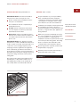
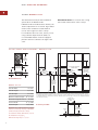
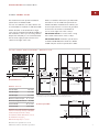
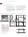
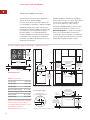
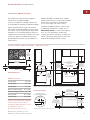
E LECTRIC C OOKTOPS
I NSTALLATION I NSTRUCTIONS
C O N TA C T
I N F O R M AT I O N
Wolf Customer
Service:
800-332-9513
Website:
wolfappliance.com
As you follow these instructions, you will
notice WARNING and CAUTION symbols.
This blocked information is important for the
safe and efficient installation of Wolf equipment. There are two types of potential
hazards that may occur during installation.
signals a situation where minor injury or
product damage may occur if you do not
follow instructions.
states a hazard that may cause serious
injury or death if precautions are not
followed.
Another footnote we would like to identify is
IMPORTANT NOTE: This highlights information that is especially relevant to a problemfree installation.
WOLF ® is a registered trademark of Wolf Appliance, Inc.
W O L F E L E C T R I C C O O K TO P S
I N S TA L L AT I O N R E Q U I R E M E N T S
IMPORTANT NOTE: Save these Installation
Instructions for the local inspector’s use.
Please read the entire Installation Instructions prior to installation.
This installation must be completed by a
qualified technician.
Installer: please retain these instructions
for local inspector’s reference, then leave
them with the homeowner.
Homeowner: please read and keep these
instructions for future reference and be sure
to read the entire Use & Care Information
prior to use.
IMPORTANT NOTE: This appliance must be
installed in accordance with National Electrical
Codes, as well as all state, municipal and local
codes. The correct voltage, frequency and
amperage must be supplied to the appliance
from a dedicated, grounded circuit which is
protected by a properly sized circuit breaker or
time delay fuse. The proper voltage, frequency,
and power ratings are listed on the product
rating plate.
Record the model and serial numbers before
installing the cooktop. Both numbers are on
the rating plate, located on the underside of
the cooktop. Refer to the illustration below.
B E F O R E Y O U S TA R T
Proper installation is your responsibility.
Have a qualified technician install this
cooktop. You must also assure that electrical installation is adequate and in compliance with all local codes and ordinances.
Installations and repairs must be performed
by a qualified or licensed contractor or
electrician qualified or licensed by the state,
province, or region where this appliance is
being installed.
Make sure you have everything necessary
for correct installation. It is the responsibility of the installer to comply with the
installation clearances specified in this book
and on the product rating plate. The rating
plate is located on the underside of the
cooktop. Refer to the illustration below.
R AT I N G P L AT E
I N F O R M AT I O N
Model Number
Serial Number
Electrical ground is required; see Electrical
Requirements on page 14.
Warranty service must be preformed by a
Wolf authorized service center.
This cooktop is intended for indoor use.
HIGH
OFF
ON
SIM
OFF
T
MEL
HIGH
ON
2
ZONE E 3
ZON
H
HIG
OFF
SIM
ON
E
BRIDG
ON
OFF
H
HIG
O
CLE
AR
SIM
Location of rating
plate under cooktop
Rating plate location
3
W O L F E L E C T R I C C O O K TO P S
S I T E P R E PA R AT I O N
IMPORTANT NOTE: Installation of the Wolf
electric cooktop must meet the following
location requirements. All dimensions listed
are minimum requirements for safe operation.
Refer to the illustration below.
To eliminate the risk of burns or fire by
reaching over heated surface units,
cabinet storage space located above the
surface units should be avoided. If
cabinet storage is to be provided, the risk
can be reduced by installing a ventilation
hood that projects horizontally a
minimum of 5" (127) beyond the bottom
cabinets.
L O C AT I O N I N C O U N T E R T O P
A) Minimum flat countertop surface. Must be
equal to or greater than cooktop width.
B) Minimum 1" (25) wide clearance from the
cooktop side edge to any combustible
surface up to 18" (457) above the cooktop
(noted by shaded area).
OVERHEAD C ABINET DIMENSIONS
C) Minimum spacing between overhead side
cabinets must be greater than or equal to
the nominal width of the cooktop unit(s).
D) Minimum 18" (457) vertical distance from
the countertop to the bottom of side
cabinets within minimum side clearance.
E) Minimum vertical distance between the
countertop and combustible materials
above the cooktop must be 30" (762).
F) Minimum 1" (25) from rear wall.
G) Maximum 13" (330) depth of overhead and
side cabinets directly above and within side
clearance.
C
G
D
Failure to locate the cooktop unit
without the proper clearances will result
in a fire hazard.
E
B
F
A
B
Minimum clearances for installation
4
I N S TA L L AT I O N I N S T R U C T I O N S
I N S TA L L AT I O N S P E C I F I C A T I O N S
The illustrations on pages 6–11 provide the
overall dimensions, installation specifications
and countertop cut-out for each of the Wolf
electric cooktop models.
These cooktops are designed to fit a standard
24" (610) deep base cabinet with a 25" (635)
deep countertop. Before making the countertop cut-out, verify that the cooktop will clear
the side walls of the base cabinet below.
Clearance is required for the conduit located at
the right rear of the cooktop. Refer to the illustration below for dimensions.
F R A M E D E L E C T R I C C O O K TO P S
U N F R A M E D E L E C T R I C C O O K TO P S
For unframed models, a minimum 6 1/4" (159)
clearance is required between the countertop
and any combustible surface directly below
the cooktop.
IMPORTANT NOTE: Unframed electric
cooktops are not designed to be installed in
combination with other cooktops.
IMPORTANT NOTE: Unframed electric
cooktops cannot be installed with a downdraft
ventilation system.
For installation options of the unframed
electric cooktops, refer to Unframed Installations on pages 12–13.
For framed models, a minimum 5 3/4" (146)
clearance is required between the countertop
and any combustible surface directly below
the cooktop.
Wolf framed electric cooktops are designed to
be installed in combination with other cooktop
units.
IMPORTANT NOTE: When multiple cooktop
units are installed side by side, refer to the
countertop cut-out dimensions on page 9.
Wolf framed electric cooktops can accommodate a Wolf downdraft ventilation system.
Refer to installation instructions provided with
the downdraft for additional specifications.
11/4" (32)
2"
(51)
2"
(51)
Conduit dimensions
Dimensions in parentheses are in
millimeters unless otherwise specified.
5
W O L F E L E C T R I C C O O K TO P S
F R A M E D MODEL CT15E
The illustrations below provide installation
specifications for Model CT15E.
IMPORTANT NOTE: Do not block the cooling
fan located at the bottom of the cooktop.
If Model CT15E is installed above cabinets, the
electrical placement is not critical. A grounded
electrical box should be located within 4'
(1.2 m) of the right rear of the cooktop.
For installation above an oven, unless you are
using cabinets deeper than 24" (610), it is
recommended that the electrical supply be
placed in the base cabinet to the right of the
oven.
I N S TA L L A T I O N S P E C I F I C A T I O N S – M O D E L C T 1 5 E
21"
(533)
OVERALL
DEPTH
15" (381)
OVERALL WIDTH
33" (838) RECOMMENDED
13" max
(330)
18"
3 3/4" (96)
2"** 19 1/4" (489)
(51) COOKTOP CUT-OUT
DEPTH
5" (127)
(457)
2 1/2" min
(64)
CABINET WIDTH
2"* min (51)
13 3/8" (340)
CUT-OUT TO
COMBUSTIBLE COOKTOP CUT-OUT
WIDTH
MATERIALS
(BOTH SIDES)
4" (102)
CONDUIT
Overall Dimensions
E
36" (914)
STANDARD
FLOOR TO
COUNTERTOP
HEIGHT
MODEL CT15E
15"
(381)
15"
(381)
Overall Width
15" (381)
Overall Height
3 3/4" (96)
Overall Depth
21" (533)
Minimum Cabinet Depth
22 3/4"
Minimum Height Clearance*
(578)
4" (102)
Cut-Out Width
13 3/8" (340)
Cut-Out Depth
19 1/4" (489)
*Minimum 5 3/4" (146) clearance is required
between countertop and any combustible
surface directly below the cooktop.
NOTE: Application shown allows for installation of two 15" (381) modules side-by-side with 33" (838) recommended cabinet width. 18" (457)
recommended cabinet width for installation of single 15" (381) cooktop or module. *Minimum clearance from both side edges of cooktop cut-out
to combustible materials up to 18" (457) above countertop. **Minimum clearance from rear edge of cooktop cut-out to combustible materials up
to 18" (457) above countertop.
13 3/8" (340)
COOKTOP CUT-OUT
WIDTH
Countertop Cut-Out
19 1/4" (489)
2 1/2" min
(64)
COOKTOP
CUT-OUT DEPTH
For detailed conduit dimensions, refer to
the illustration on page 5.
Dimensions may vary to ± 1/8" (3).
6
30" (762)
COUNTERTOP TO
COMBUSTIBLE
MATERIALS
ABOVE COOKTOP
FRONT OF COUNTERTOP
I N S TA L L AT I O N I N S T R U C T I O N S
F R A M E D MODEL CT30E
The illustrations below provide installation
specifications for Model CT30E.
Refer to installation instructions provided with
the built-in oven for additional specifications.
For ease of installation, 33" (838) cabinets are
recommended for installation of Model CT30E.
If Model CT30E is installed above cabinets, the
electrical placement is not critical. A grounded
electrical box should be located within 4'
(1.2 m) of the right rear of the cooktop.
A Wolf 30" (762) or 36" (914) built-in single
oven may be installed below Model CT30E. For
this installation, unless you are using cabinets
deeper than 24" (610), it is recommended that
the electrical supply be placed in the base
cabinet to the right of the oven.
IMPORTANT NOTE: Do not block the cooling
fan located at the bottom of the cooktop.
IMPORTANT NOTE: Installation specifications
for Model CT30E-208/S are identical to Model
CT30E. Only the electrical specifications differ.
I N S TA L L AT I O N S P E C I F I C AT I O N S – M O D E L C T 3 0 E
21"
(533)
OVERALL
DEPTH
30" (762)
OVERALL WIDTH
33" (838) RECOMMENDED
13" max
(330)
18"
3 3/4" (96)
5" (127)
2"** 19 1/4" (489)
(51) COOKTOP CUT-OUT
DEPTH
(457)
2 1/2" min
(64)
2"* min (51)
CUT-OUT TO
COMBUSTIBLE
MATERIALS
(BOTH SIDES)
28 3/8" (721) COOKTOP
CUT-OUT WIDTH
CONDUIT
4" (102)
3 1/2" (89)
Overall Dimensions
3 3/4" min
24" min
(610)
MODEL CT30E
Overall Width
30" (762)
Overall Height
3 3/4" (96)
Overall Depth
21" (533)
Minimum Cabinet Depth
30" (762)
COUNTERTOP TO
COMBUSTIBLE
MATERIALS
ABOVE COOKTOP
CABINET WIDTH
30" min (762)
22 3/4"
Minimum Height Clearance*
(95)
36" (914)
STANDARD
FLOOR TO
COUNTERTOP
HEIGHT
E
10"
(254)
30-INCH OVEN OPENING
*Minimum clearance from both side edges of cooktop cut-out to combustible materials up to 18" (457) above countertop. **Minimum clearance
from rear edge of cooktop cut-out to combustible materials up to 18" (457) above countertop.
(578)
4" (102)
Cut-Out Width
28 3/8" (721)
Cut-Out Depth
19 1/4" (489)
*Minimum 5 3/4" (146) clearance is required
between countertop and any combustible
surface directly below the cooktop.
28 3/8" (721)
COOKTOP CUT-OUT WIDTH
Countertop Cut-Out
19 1/4" (489)
COOKTOP
CUT-OUT DEPTH
2 1/2" min
(64)
For detailed conduit dimensions, refer to
the illustration on page 5.
Dimensions may vary to ± 1/8" (3).
Dimensions in parentheses are in
millimeters unless otherwise specified.
FRONT OF COUNTERTOP
7
W O L F E L E C T R I C C O O K TO P S
F R A M E D MODEL CT36E
The illustrations below provide installation
specifications for Model CT36E.
Refer to installation instructions provided with
the built-in oven for additional specifications.
For ease of installation, 39" (991) cabinets are
recommended for installation of Model CT36E.
If Model CT36E is installed above cabinets, the
electrical placement is not critical. A grounded
electrical box should be located within 4'
(1.2 m) of the right rear of the cooktop.
A Wolf 30" (762) or 36" (914) built-in single
oven may be installed below Model CT36E. For
this installation, unless you are using cabinets
deeper than 24" (610), it is recommended that
the electrical supply be placed in the base
cabinet to the right of the oven.
IMPORTANT NOTE: Do not block the cooling
fan located at the bottom of the cooktop.
I N S TA L L A T I O N S P E C I F I C A T I O N S – M O D E L C T 3 6 E
21"
(533)
OVERALL
DEPTH
36" (914)
OVERALL WIDTH
13" max
(330)
18"
3 3/4" (96)
5" (127)
2"** 19 1/4" (489)
(51) COOKTOP CUT-OUT
DEPTH
(457)
2 1/2" min
(64)
2"* min (51)
CUT-OUT TO
COMBUSTIBLE
MATERIALS
(BOTH SIDES)
CONDUIT
34 3/8" (873)
COOKTOP CUT-OUT WIDTH
3 1/2" (89)
3 3/4" min (95)
24" min
(610)
MODEL CT36E
Overall Width
36" (914)
Overall Height
3 3/4" (96)
Overall Depth
21" (533)
22 3/4"
Minimum Height Clearance*
36" (914)
STANDARD
FLOOR TO
COUNTERTOP
HEIGHT
(254)
36-INCH OVEN OPENING
*Minimum clearance from both side edges of cooktop cut-out to combustible materials up to 18" (457) above countertop. **Minimum clearance from
rear edge of cooktop cut-out to combustible materials up to 18" (457) above countertop.
34 3/8" (873)
COOKTOP CUT-OUT WIDTH
4" (102)
34 3/8" (873)
Cut-Out Depth
19 1/4" (489)
*Minimum 5 3/4" (146) clearance is required
between countertop and any combustible
surface directly below the cooktop.
Countertop Cut-Out
19 1/4" (489)
COOKTOP
CUT-OUT DEPTH
2 1/2" min
(64)
For detailed conduit dimensions, refer to
the illustration on page 5.
Dimensions may vary to ± 1/8" (3).
E
10"
(578)
Cut-Out Width
8
30" (762)
COUNTERTOP TO
COMBUSTIBLE
MATERIALS
ABOVE COOKTOP
4" (102)
Overall Dimensions
Minimum Cabinet Depth
39" (991)
RECOMMENDED CABINET WIDTH
36" min (914)
FRONT OF COUNTERTOP
I N S TA L L AT I O N I N S T R U C T I O N S
M U LT I P L E C O O K TO P I N S T A L L A T I O N
If the framed electric cooktop is to be used
with any combination of additional cooktop
units or modules with a filler strip, the cut-out
width is calculated by adding the corresponding units' cut-out dimensions plus 1 1/4" (32)
for each additional unit. Refer to the illustration below.
IMPORTANT NOTE: For Model CT15E, the
cut-out width should be increased from 13 3/8"
(340) to 14" (356) when installed with multiple
units.
When two or more modules are installed
together, an integrated module filler strip
(# 802726) is recommended. If a 30" (762)
downdraft ventilation system is also installed,
an integrated module support for downdraft
ventilation (# 803386) is also required. Contact
your Wolf dealer for information on these
accessory components.
IMPORTANT NOTE: Unframed electric
cooktops Models CT30EU and CT36EU are not
designed to be installed in combination with
other cooktop units.
ACCESSORIES
Optional accessories are available
through your
Wolf dealer. To
obtain local dealer
information, visit
the Showroom
Locator section of
our website,
wolfappliance.com.
IMPORTANT NOTE: When multiple units are
installed side by side, each unit must have its
own separate recommended electrical circuit.
593/4" (1518) FOUR MODULES WIDTH OR
591/2" (1511) 30" COOKTOP AND TWO MODULES OR
501/4" (1276) 36" COOKTOP AND ONE MODULE
441/2" (1130) THREE MODULES WIDTH OR
441/4" (1124) 30" COOKTOP AND ONE MODULE
291/4" (743)
TWO MODULES WIDTH
21/2"min
(64)
14"
191/4"
(356)
CUT-OUT
WIDTH
(489)
CUT-OUT
DEPTH
FRONT OF COUNTERTOP
Countertop cut-out dimensions for installation of multiple cooktops
Dimensions in parentheses are in
millimeters unless otherwise specified.
9
W O L F E L E C T R I C C O O K TO P S
U N F R A M E D MODEL CT30EU
The illustrations below provide installation
specifications for Model CT30EU.
For ease of installation, 33" (838) cabinets are
recommended for installation of Model CT30EU.
If Model CT30EU is installed above cabinets,
electrical placement is not critical. A grounded
electrical box should be located within 4'
(1.2 m) of the right rear of the cooktop.
For Model CT30EU installation options, refer
to Unframed Installations on pages 12–13.
A Wolf 30" (762) built-in single oven may be
installed below Model CT30EU. For this installation, unless you are using cabinets deeper
than 24" (610), it is recommended that the
electrical supply be placed in the base cabinet
to the right of the oven. Refer to installation
instructions provided with the built-in oven for
additional specifications.
IMPORTANT NOTE: For flush mount applications, it is recommended to measure the
cooktop glass before cutting the countertop to
ensure a proper fit. Small variances may exist
between the template and the cooktop.
I N S TA L L AT I O N S P E C I F I C AT I O N S – M O D E L C T 3 0 E U
21"
(533)
OVERALL
DEPTH
30" (762)
OVERALL WIDTH
33" (838) RECOMMENDED
13" max
(330)
18"
2"* min (51)
CUT-OUT TO
COMBUSTIBLE
MATERIALS
(BOTH SIDES)
(457)
4 1/4" (108)
5 1/2" (140)
SEE COUNTERTOP
CUT-OUT BELOW
CONDUIT
3 1/2" (89)
4" min (102)
24" min
(610)
MODEL CT30EU
Overall Width
30" (762)
Overall Height
4 1/4" (108)
Overall Depth
21" (533)
22 3/4"
Cut-Out Width
28 3/8" (721)
Cut-Out Depth
19 3/8" (492)
*Minimum 6 1/4" (159) clearance is required
between countertop and any combustible
surface directly below the cooktop.
For detailed conduit dimensions, refer to
the illustration on page 5.
Dimensions may vary to ± 1/8" (3).
36" (914)
STANDARD
FLOOR TO
COUNTERTOP
HEIGHT
TO OVEN
OPENING
E
10"
(254)
30-INCH OVEN OPENING
*Minimum clearance from both side edges and back edge of cooktop cut-out to combustible materials up to 18" (457) above countertop.
(578)
Minimum Height Clearance* 4 1/2" (114)
10
SEE COUNTERTOP
CUT-OUT BELOW
4 1/2" (114)
4" min (102)
Overall Dimensions
Minimum Cabinet Depth
30" (762)
COUNTERTOP TO
COMBUSTIBLE
MATERIALS
ABOVE COOKTOP
CABINET WIDTH
30" min (762)
Countertop Cut-Out
1 5/16" (33)
RECESSED AREA FOR
FLUSH MOUNT INSTALLATION ONLY
RADIUS
30 1/8"** (765)
RECESSED AREA FOR
FLUSH MOUNT INSTALLATION ONLY
28 3/8" (721) COOKTOP
CUT-OUT WIDTH
2"* (51)
COUNTERTOP
PROFILE
7/8"
(22) max
21 1/8"** (537)
RECESSED AREA
FOR FLUSH MOUNT
INSTALLATION ONLY
5/16" (8)
7/16" (11) RADIUS
19 3/8" (492)
COOKTOP
CUT-OUT DEPTH
1 9/16" (40)
FRONT OF COUNTERTOP
**Minimum dimension, but may be exceeded by up to 1/8" (3).
2 7/16" (62)
I N S TA L L AT I O N I N S T R U C T I O N S
U N F R A M E D MODEL CT36EU
If Model CT36EU is installed above cabinets,
electrical placement is not critical. A grounded
electrical box should be located within 4'
(1.2 m) of the right rear of the cooktop.
The illustrations below provide installation
specifications for Model CT36EU.
For ease of installation, 39" (991) cabinets are
recommended for installation of Model CT36EU.
For Model CT36EU installation options, refer
to Unframed Installations on pages 12–13.
A Wolf 36" (914) built-in single oven may be
installed below Model CT36EU. For this installation, unless you are using cabinets deeper than
24" (610), it is recommended that the electrical
supply be placed in the base cabinet to the right
of the oven. Refer to installation instructions
provided with the built-in oven for additional
specifications.
IMPORTANT NOTE: For flush mount applications, it is recommended to measure the
cooktop glass before cutting the countertop to
ensure a proper fit. Small variances may exist
between the template and the cooktop.
I N S TA L L AT I O N S P E C I F I C AT I O N S – M O D E L C T 3 6 E U
21"
(533)
OVERALL
DEPTH
36" (914)
OVERALL WIDTH
13" max
(330)
18"
2"* min (51)
CUT-OUT TO
COMBUSTIBLE
MATERIALS
(BOTH SIDES)
(457)
4 1/4" (108)
5 1/2" (140)
SEE COUNTERTOP
CUT-OUT BELOW
CONDUIT
SEE COUNTERTOP
CUT-OUT BELOW
3 1/2" (89)
4" min (102)
24" min
(610)
MODEL CT36EU
Overall Width
36" (914)
Overall Height
4 1/4" (108)
Overall Depth
21" (533)
22 3/4"
36" (914)
STANDARD
FLOOR TO
COUNTERTOP
HEIGHT
TO OVEN
OPENING
Cut-Out Width
34 3/8" (873)
Cut-Out Depth
19 3/8" (492)
*Minimum 6 1/4" (159) clearance is required
between countertop and any combustible
surface directly below the cooktop.
For detailed conduit dimensions, refer to
the illustration on page 5.
Dimensions may vary to ± 1/8" (3).
Dimensions in parentheses are in
millimeters unless otherwise specified.
E
10"
(254)
36-INCH OVEN OPENING
*Minimum clearance from both side edges and back edge of cooktop cut-out to combustible materials up to 18" (457) above countertop.
(578)
Minimum Height Clearance* 4 1/2" (114)
30" (762)
COUNTERTOP TO
COMBUSTIBLE
MATERIALS
ABOVE COOKTOP
4 1/2" (114)
4" min (102)
Overall Dimensions
Minimum Cabinet Depth
39" (991)
RECOMMENDED CABINET WIDTH
36" min (914)
Countertop Cut-Out
1 5/16" (33)
RECESSED AREA FOR
FLUSH MOUNT INSTALLATION ONLY
RADIUS
36 1/8"** (918)
RECESSED AREA FOR
FLUSH MOUNT INSTALLATION ONLY
34 3/8" (873)
COOKTOP CUT-OUT WIDTH
2"* (51)
COUNTERTOP
PROFILE
7/8"
(22) max
21 1/8"** (537)
RECESSED AREA
FOR FLUSH MOUNT
INSTALLATION ONLY
5/16" (8)
7/16" (11) RADIUS
19 3/8" (492)
COOKTOP
CUT-OUT DEPTH
1 9/16" (40)
FRONT OF COUNTERTOP
**Minimum dimension, but may be exceeded by up to 1/8" (3).
2 7/16" (62)
11
W O L F E L E C T R I C C O O K TO P S
U N F R A M E D I N S T A L L AT I O N S
F L U S H M O U N T I N S TA L L A T I O N
Flush mount installations are intended
for granite, solid surface or stone countertop surfaces only. Failure to use high
heat resistant surface will result in countertop damage if hot cooking utensils are
accidentally moved off the cooking
surface.
MODELS CT30EU AND CT36EU
Unframed electric cooktop Models CT30EU and
CT36EU can be mounted flush with the top of
the countertop or as a frameless installation
with the glass mounted on top of the countertop surface.
IMPORTANT NOTE: The materials required
for a flush mount installation are provided with
the unframed Models CT30EU and CT36EU.
Refer to the instructions provided with the
unframed cooktop installation kit (# 811358) for
additional specifications.
There are two options for a flush mount
installation of the unframed electric cooktop;
Option 1 and Option 2.
OPTION 1: For this flush mount installation, a
recessed area surrounding the standard countertop cut-out is required. Fabrication of the
recessed area must take place before the final
countertop installation. A template of the countertop cut-out is provided with the unframed
cooktop for fabrication purposes.
IMPORTANT NOTE: This fabrication method is
not recommended for molded backsplash style
countertops (triple cove).
For countertop cut-out dimensions, refer to
the Installation Specifications illustration on
page 10 for Model CT30EU and page 11 for
Model CT36EU.
In order to rout the required recessed area for
this flush mount installation, a second
template must be made from 1/2" (13) plywood.
The template will be used as a guide for a top
bearing router bit.
Make the wood template wide enough so that
clamps used to hold this template to the countertop do not interfere with the router base.
The cut-out dimension of the wood template
should match the outer perimeter of the
template supplied with the cooktop.
Center the wood template over the existing
cut-out in the countertop and clamp. It may be
helpful to use medium-strength double-sided
tape to adhere the template to the countertop;
this will keep the template from shifting during
the routing operation. Make sure that the
adhesive can be easily removed by testing it
on a scrap piece of the countertop. Using a top
bearing router bit with the wood template as a
guide, rout out a 5/16" (8) deep recessed area in
the countertop cut-out.
12
Dimensions in parentheses are in
millimeters unless otherwise specified.
I N S TA L L AT I O N I N S T R U C T I O N S
U N F R A M E D I N S TA L L AT I O N S
F L U S H M O U N T I N S TA L L AT I O N
F R A M E L E S S I N S TA L L A T I O N
OPTION 2: For this flush mount installation,
the countertop cut-out will be the same size as
the outer edge of the glass top. It is recommended that cooktop itself be used as the
template for the cut-out. Turn the cooktop over
and mark the opening using the glass top as a
template.
Unframed electric cooktop Models CT30EU
and CT36EU can be installed as a frameless
application, with the glass mounted on top of
the countertop surface. For countertop cut-out
dimensions, refer to the Installation Specifications illustration on page 10 for Model CT30EU
and page 11 for Model CT36EU.
It will be necessary to attach L-shaped brackets
or cleats to the inner perimeter of the cut-out
to support the cooktop. The top edge of the
bracket can be no wider than 7/8" (22) and will
be attached 5/16" (8) below the surface of the
countertop. Refer to the illustration below.
Attachment of the brackets is up to the
installer's discretion, wherever enough countertop material is present.
For additional support in the cut-out area,
adhere scrap countertop material to the
bottom side of the countertop. Consult your
countertop supplier for the proper methods of
attachment.
5/16" (8)
L-Shaped
Brackets
7/8" (22)
Flush mount installation brackets
13
W O L F E L E C T R I C C O O K TO P S
ELECTRICAL R E Q U I R E M E N T S
Verify that power is disconnected from
the electrical box before proceeding.
R E Q U I R E D P O W E R S U P P LY
Model CT15E
240 V AC / 60 Hz / 20 amp service
208 V AC / 60 Hz / 15 amp service
Models CT30E and CT30EU
240 V AC / 60 Hz / 40 amp service
208 V AC / 60 Hz / 40 amp service
Model CT30E-208/S
208 V AC / 60 Hz / 40 amp service
Models CT36E and CT36EU
240 V AC / 60 Hz / 50 amp service
208 V AC / 60 Hz / 40 amp service
MAXIMUM CONNECTED LOAD
Model CT15E
3.7 kW at 240 V AC
2.8 kW at 208 V AC
Models CT30E and CT30EU
8.1 kW at 240 V AC
6.1 kW at 208 V AC
Model CT30E-208/S
7.9 kW at 208 V AC
Models CT36E and CT36EU
10.5 kW at 240 V AC
7.9 kW at 208 V AC
14
The Wolf electric cooktop requires a separate,
grounded 3-wire service with its own circuit
breaker. Locate the electrical supply within the
shaded area shown in the Installation Specifications illustration for your specific model on
pages 6–11.
This appliance must be installed in accordance
with National Electrical Codes, as well as all
state, municipal and local codes. The correct
voltage, frequency and amperage must be
supplied to the appliance from a dedicated,
grounded circuit which is protected by a
properly sized circuit breaker or time delay
fuse. The proper voltage, frequency and power
ratings are listed on the product rating plate,
located on the underside of the cooktop. Refer
to the illustration on page 3 for location of the
rating plate.
I N S TA L L AT I O N I N S T R U C T I O N S
ELECTRICAL R E Q U I R E M E N T S
For Electrical Installation – attach the
conductors to the residence wiring in accordance with National Electrical Codes and all
state, provincial, municipal and local codes.
Dimensions in parentheses are in
millimeters unless otherwise specified.
The complete appliance must be properly
grounded at all times when electrical
power is applied.
Do not ground the appliance with the
neutral (white) house supply wire. A
separate ground wire must be utilized.
I M P O R TA N T
N OT E
If aluminum house supply wiring is
utilized, splice the appliance copper wire
to the aluminum house wiring using
special connectors designed and agency
certified for joining copper and
aluminum. Follow the connector manufacturer's recommended procedure carefully. Improper connection can result in a
fire hazard!
This appliance
must be installed
in accordance
with National
Electrical Codes,
as well as all
state, municipal
and local codes.
15
W O L F E L E C T R I C C O O K TO P S
C O O K T O P I N S TA L L AT I O N
Attach the foam strip to the underside of the
cooktop frame. Refer to the illustration below.
If the ceramic glass top of the cooktop is
broken, turn off power to the unit. Do
not operate until glass has been replaced
by a Wolf authorized service center.
IMPORTANT NOTE: For frameless installations, adhere the foam strip to the outer edge
of the glass, not the support frame.
IMPORTANT NOTE: The materials required
for a flush mount installation are provided with
the unframed Models CT30EU and CT36EU.
Refer to the instructions provided with the
unframed cooktop installation kit (# 811358).
Gently lower the unit into the cut-out area in
the countertop and center. Check that the front
edge of cooktop is parallel to the front edge of
the countertop. Check that all required clearances are met.
Attach the brackets to the bottom of the unit,
as shown in the illustration below. Install the
clamping screws into the bracket and tighten
until the screws contact the underside of the
countertop. Do not overtighten the screws.
IMPORTANT NOTE: Do not seal the cooktop
to the countertop. It must be removed if
service is necessary.
COOKTOP
COOKTOP
COUNTERTOP
FOAM
STRIP
BRACKET
BRACKET
SCREWS
Foam strip
16
Installation brackets
4" (102)
CLAMPING
SCREW
I N S TA L L AT I O N I N S T R U C T I O N S
B E F O R E O P E R AT I N G T H E C O O K T O P
C O O K T O P R E M OVA L
Clean the ceramic glass surface carefully using
the Cooktop Cleaning Crème provided with the
cooktop. Remove all cleaning residue.
IMPORTANT NOTE: This procedure should
only be performed by a Wolf authorized
service center.
Read the entire Wolf Electric Cooktops
Use & Care Information included with the
cooktop. Important safety, service and
warranty information is contained within the
book.
If it is necessary to remove the cooktop for
cleaning or service, disconnect the electrical
supply. Remove the mounting brackets on the
right and left side of the unit and remove the
cooktop. Reinstall in the reverse order.
IMPORTANT NOTE: For flush mount installations, use a razor blade to carefully cut around
the RTV perimeter seal. A new RTV installation
kit (# 811358) will be required to reinstall the
cooktop. This kit is available through your
Wolf dealer. To obtain local dealer information,
visit the Showroom Locator section of our
website, wolfappliance.com.
Dimensions in parentheses are in
millimeters unless otherwise specified.
ACCESSORIES
Optional accessories are available
through your
Wolf dealer. To
obtain local dealer
information, visit
the Showroom
Locator section of
our website,
wolfappliance.com.
17
W O L F E L E C T R I C C O O K TO P S
ACCESSORIES
Optional accessories are available
through your
Wolf dealer. To
obtain local dealer
information, visit
the Showroom
Locator section of
our website,
wolfappliance.com.
V E N T I L AT I O N O P T I O N S
TROUBLES H O OT I N G
IMPORTANT NOTE: It is recommended that
you operate the Wolf electric cooktop with
either a Wolf cooktop ventilation hood, downdraft system or Pro ventilation hood. Contact
your Wolf dealer for details.
I F C O O K T O P D O E S N O T O P E R AT E
Cooktop Wall Hood – 30" (762) or 36" (914)
widths in classic stainless steel.
Cooktop Island Hood – 42" (1067) width in
classic stainless steel.
Downdraft Ventilation System –
30" (762), 36" (914) or 45" (1143) widths,
with top cover and control panel in classic,
platinum and carbon stainless steel
finishes—45" (1143) downdraft available
in classic finish only. Not for use with
Model CT30EU or Model CT36EU.
Pro Wall Hood – 22" (559), 24" (610) or
27" (686) depths and 30" (762) to 66" (1676)
widths in classic stainless steel.
Pro Wall Chimney Hood – 36" (914) to
54" (1372) widths in classic stainless steel.
Pro Island Hood – 36" (914) to 66" (1676)
widths in classic stainless steel.
Pro Hood Liner – available in widths to
accommodate 36" (914) to 60" (1524) hoods.
All hoods have welded seams, sealed halogen
lighting and removable, dishwasher-safe filters.
Blower requirements may vary due to the
length of ducting and number of angles. The
basic recommendation is 1 CFM per 100 Btu/hr
(1 kW equals 3,415 Btu/hr). Always consult
your HVAC professional for more concise
blower requirements.
IMPORTANT NOTE: When installing a ventilation hood, refer to the specific requirements
of the hood for the minimum dimension to
countertop.
18
IMPORTANT NOTE: If the electric cooktop
does not operate properly, follow these
troubleshooting steps:
Verify that power is being supplied to the
cooktop.
Check electrical connections to ensure that
the installation has been completed
correctly.
Follow troubleshooting procedures as
described in the Wolf Electric Cooktops
Use & Care Information.
If the cooktop still does not work, contact
a Wolf authorized service center. Do not
attempt to repair the cooktop yourself.
Wolf is not responsible for service required
to correct a faulty installation.
This cooktop must be repaired only by a
Wolf authorized service center. The unit
must be disconnected from power prior
to service.
I N S TA L L AT I O N I N S T R U C T I O N S
I F Y O U N E E D S E RV I C E
If service is necessary, maintain the quality
built into your electric cooktop by calling a
Wolf authorized service center.
To obtain the name and number of a
Wolf authorized service center, check
the Contact & Support section of our
website, wolfappliance.com or call Wolf
Customer Service at 800-332-9513.
When calling for service, you will need the
cooktop model and serial numbers. Both
numbers are listed on the rating plate,
located on the underside of the cooktop.
Refer to the illustration on page 3 for
location of the rating plate.
C O N TA C T
I N F O R M AT I O N
Wolf Customer
Service:
800-332-9513
Website:
wolfappliance.com
The information and images in this book are the
copyright property of Wolf Appliance, Inc., an
affiliate of Sub-Zero, Inc. Neither this book nor any
information or images contained herein may be
copied or used in whole or in part without the
express written permission of Wolf Appliance, Inc.,
an affiliate of Sub-Zero, Inc.
©Wolf Appliance, Inc. all rights reserved.
19
WOLF APPLIANCE, INC.
812358
12 / 2007
P. O . B O X 4 4 8 4 8
MADISON, WI 53744
800-332-9513
W O L FA P P L I A N C E . C O M