1
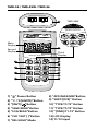
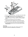
TMD-55 / TMD-55W
Multilogger Thermometer
/ Wireless Download
TMD-56
Multilogger Thermometer
with USB Download
Users Manual
• Mode d’emploi
• Bedienungshandbuch
• Manual d’Uso
• Manual de uso
Multilogger Thermometer
/ Wireless Download
TMD-56
Multilogger Thermometer
with USB Download
Users Manual
June 2010, Rev.1
©2010 Amprobe Test Tools.
All rights reserved. Printed in Taiwan
English
TMD-55 / TMD-55W
Limited Warranty and Limitation of Liability
Your Amprobe product will be free from defects in material and
workmanship for 1 year from the date of purchase. This warranty
does not cover fuses, disposable batteries or damage from accident,
neglect, misuse, alteration, contamination, or abnormal conditions
of operation or handling. Resellers are not authorized to extend
any other warranty on Amprobe’s behalf. To obtain service during
the warranty period, return the product with proof of purchase
to an authorized Amprobe Test Tools Service Center or to an
Amprobe dealer or distributor. See Repair Section for details. THIS
WARRANTY IS YOUR ONLY REMEDY. ALL OTHER WARRANTIES WHETHER EXPRESS, IMPLIED OR STAUTORY - INCLUDING IMPLIED
WARRANTIES OF FITNESS FOR A PARTICULAR PURPOSE OR
MERCHANTABILITY, ARE HEREBY DISCLAIMED. MANUFACTURER
SHALL NOT BE LIABLE FOR ANY SPECIAL, INDIRECT, INCIDENTAL
OR CONSEQUENTIAL DAMAGES OR LOSSES, ARISING FROM ANY
CAUSE OR THEORY. Since some states or countries do not allow the
exclusion or limitation of an implied warranty or of incidental or
consequential damages, this limitation of liability may not apply
to you.
Repair
All test tools returned for warranty or non-warranty repair or
for calibration should be accompanied by the following: your
name, company’s name, address, telephone number, and proof of
purchase. Additionally, please include a brief description of the
problem or the service requested and include the test leads with
the meter. Non-warranty repair or replacement charges should be
remitted in the form of a check, a money order, credit card with
expiration date, or a purchase order made payable to Amprobe®
Test Tools.
In-Warranty Repairs and Replacement – All Countries
Please read the warranty statement and check your battery before
requesting repair. During the warranty period any defective test
tool can be returned to your Amprobe® Test Tools distributor for
an exchange for the same or like product. Please check the “Where
to Buy” section on www.amprobe.com for a list of distributors near
you. Additionally, in the United States and Canada In-Warranty
repair and replacement units can also be sent to a Amprobe® Test
Tools Service Center (see address below).
Non-Warranty Repairs and Replacement – US and Canada
Non-warranty repairs in the United States and Canada should be
sent to a Amprobe® Test Tools Service Center. Call Amprobe® Test
Tools or inquire at your point of purchase for current repair and
replacement rates.
In USA Amprobe Test Tools Everett, WA 98203 Tel: 877-AMPROBE (267-7623) In Canada
Amprobe Test Tools
Mississauga, ON L4Z 1X9
Tel: 905-890-7600
Non-Warranty Repairs and Replacement – Europe
European non-warranty units can be replaced by your Amprobe®
Test Tools distributor for a nominalv charge. Please check the
“Where to Buy” section on www.amprobe.com for a list of
distributors near you.
European Correspondence Address*
Amprobe® Test Tools Europe
In den Engematten 14
79286 Glottertal, Germany
Tel.: +49 (0) 7684 8009 - 0
*(Correspondence only – no repair or replacement available from
this address. European customers please contact your distributor.)
TMD-55 / TMD-55W / TMD-56
T1 T2
TMD-55W
14
Multilogger Thermometer
with Wireless Download
TMD-55
Main
Display
13
Second
Display
Multilogger Thermometer
Third
Display
2
3
5
6
8
9
1
4
7
11
12
10
1) “ ” Power Button
8) “APO/MAX/MIN”Button
2) “°C /°F/[LIMITS]”Button
9) “SHIFT/[OFS]” Button
3) “[INVT]/
10) “TYPE/T1/T2” Button
”Button
4) “SAVE/READ”Button
11) “TYPE/T1/T2” Button
5) “LOG/READ”Button
12) “[TIME]/T1-T2” Button
6) “CLR ?/SET [ ]”Button
13) LCD Display
7) “REL/HOLD”Mode
14) T1/T2 Input
Screen Display
9
10
11
1.3
1.1
1.2
1
4
5
6
8
12
14
2.2
2.1
2.3
2
1)Main display
3.2
3.1 3.3
3
7
13
4)MAX/MIN reading
1.1)Degrees °C / °F
5)Relative mode
1.2)Type of T/C
thermocouple
6)Hi/Lo Limits
comparative mode
1.3)T1 or T2
temperature
7)Data SAVE/LOG and READ
mode
2)Second display
8)Shift mode
2.1)Degrees °C / °F
9)Low BATT display
2.2)Type of T/C
thermocouple
10)Auto power off
2.3)T1 or T2
temperature
3)Third display
11)Main display
DataHOLD mode
12)Wireless Mode
(TMD-55W)
3.1)Degrees °C / °F
13)Commutation mode
3.2)Time or Date display
14)SET mode
3.3)T1-T2 differential
CONTENTS
SYMBOLS........................................................................... 3
UNPACKING AND INSPECTION......................................... 5
INTRODUCTION................................................................. 5
Features......................................................................... 5
OPERATION INSTRUCTIONS.............................................. 7
Operational Mode........................................................ 7
Normal Mode.............................................................. 7
Shift Mode.................................................................. 7
Setup Mode................................................................ 8
Wireless Mode (For TMD-55W).................................. 8
To check the channel and ID of the mete................. 8
Normal Mode.............................................................. 8
“ “ Power Button..................................................... 8
“[LIMITS]” Button....................................................... 8
“
” Button................................................................ 9
“SAVE/READ” Button................................................. 9
“LOG/READ” Button................................................... 9
“HOLD” Mode............................................................ 10
“MAX/MIN” with Time record mode........................ 10
“T1/T2” Button (Main display)................................... 11
“T1/T2” Button (Second display)............................... 11
“[TIME]/T1-T2” Button (Third display)...................... 11
Shift Mode..................................................................... 11
“°C/°F” Button............................................................ 11
1
“SAVE” Button............................................................ 12
“LOG” Button............................................................. 12
“CLR ?” Button........................................................... 13
“REL” Button.............................................................. 13
“APO” Button............................................................. 13
“TYPE” Button (Main display)................................... 13
“TYPE” Button (Second display)................................ 14
Setup Mode................................................................ 14
“[LIMITS]” Button....................................................... 14
“[INVT]” Button.......................................................... 14
“APO” Button............................................................. 15
“[OFS]” Button........................................................... 15
“[TIME]” Button......................................................... 15
Error messages.............................................................. 15
SPECIFICATION................................................................... 16
MAINTENANCE.................................................................. 19
2
SYMBOLS
�
Caution! Refer to the explanation in this Manual
�
Complies with European Directives
Tested Comply With FCC Standards
=
Do not dispose of this product as unsorted
municipal waste.
�WARNING and PRECAUTIONS
• To avoid electrical shock, do not use this instrument
when working voltages at the measurement surface
over 24V AC or DC.
• To avoid damage or burns, do not make
temperature measurement in microwave ovens.
• Repeated sharp flexing can break the thermocouple
leads. To prolong lead life, avoid sharp bends in the
leads, especially near the connector.
Federal Communications Commission
The devices TMD-55W are complied with Part 15 of the
FCC Rules.
Operation is subject to the following two conditions:
(1) this device may not cause harmful interference,
and (2) this device must accept any interference
received,including interference that may cause undesired
operation.
Note
The equipments TMD-55W have been tested and found
to comply with the limits for a Class B digital device,
pursuant to Part 15 of the FCC Rules.
These limits are designed to provide reasonable
protection. This equipment generates, uses and can
radiated radio frequency energy and, if not installed
3
and used in accordance with the instructions, may cause
harmful interference to radio communications. However,
there is no guarantee that interference will not occur
in a particular installation if this equipment does cause
harmful interference to radio or television reception,
which can be determined by turning the equipment
off and on, the user is encouraged to try to correct the
interference by one or more of the following measures:
• Reorient or relocate the receiving antenna.- Increase
the separation between the equipment and receiver.
• Connect the equipment into an outlet on a
circuit different from that to which the receiver is
connected.
• Consult the dealer or an experienced radio/TV
technician for help.
Shielded interface cables must be used in order to comply
with emission limits.
Changes or modifications not expressly approved by the
party responsible for compliance could void the user’s
authority to operate the equipment.
Wireless Note
Wireless receiver must keep a distance at least 40cm from
the meter and meter to meter distance must be at least
30cm.
4
Unpacking and Inspection
Your shipping carton should include:
1 Meter
1 Manual
1 USB Cable (TMD-56)
1 Software CD ROM (TMD-56 / TMD-55W)
4 AAA Batteries
2 K type Thermocouple
1 Plain white box
If any of the items are damaged or missing, return
the complete package to the place of purchase for an
exchange.
INTRODUCTION
TThe instrument is a portable digital thermometer that
measures external thermocouples of type K, J, R, S, T, E,
N. The thermocouples types comply with the N.I.S.T. – ITS
90 standard reference temperature/voltage tables. The
thermometer features a dual thermocouple input and an
adjustable T/C offset.
Features
TMD-55 and TMD-55W
• Wireless two ways transmission. (TMD-55W only)
• Dual input function.
• Basic accuracy: 0.05%
• 2 Channel Temperature Measuring:
T1, T2 for various thermocouples.
• Triple displays with set-able backlight:
MAIN display for T1, T2.
SECOND display for T1, T2.
5
THIRD display for T1- T2, TIME.
DATA LOGGER function
• Data logger capacity:
Save data: 128 samples with read-time data.
Data logger: 16 sets, Maximum 1024 data capacity.
Easy Reads Data with down and up key on meter.
• T/C Offset Adjust.
• REC, MAX, MIN, MAX-MIN, AVG, REL, HOLD
functions.
• T1, T2, T1-T2, Time and Memory No.
• Resolution 0.1°C/1°C, 0.1°F/1°F.
• Warning beeper with Hi/Lo setting.
• TIME, Record interval, APO time setting.
• Real time clock with calendar.
• Selectable Auto Power Off function.
TMD-56
• USB Port provides excellent user interface.
• DC 12V adapter.
• Basic accuracy: 0.05%.
• Dual inputs with K/J/E/T/R/S/N thermocouple.
• Triple display with settable backlight.
• Real time clock and calendar.
• Data logger capacity:
Save data: 256 samples with real time data.
Data logger: 16 sets, Max 16000 data capacity.
Easy read data with uP/down keys.
• Selectable Auto Power Off function.
• Warning beeper with Hi/Lo setting.
6
• MAX/MIN/AVG/REL/HOLD function.
• MAIN display for T1/T2.
• SECOND display for T1/T2.
• THIRD display for T1-T2, with real time clock and
calendar.
Model Difference:
Model
Memories
Wireless
USB
DC IN
TMD-55
Save 128,
Log 1024
X
X
X
TMD-56
Save 256,
Log 16000
X
V
V
TMD-55W
Save 128,
Log 1024
V
X
X
OPERATING INSTRUCTIONS
Operational Mode
There are three operation modes-Normal, Shift, and
Setup Mode.
Normal Mode
This is the default mode, the operating functions for the
normal mode are printed on the top of each button in
white.
Shift Mode
The operating functions for the shift mode are printed
in white on the buttons. While in the normal mode,
press the “SHIFT” button to switch to shift mode. At
the lower-right corner of the display, the word “Shift”
is displayed to indicate shift mode. To switch back to
normal mode, press the “SHIFT” button again.
7
Setup Mode
Press the “SET[ ]” button in normal mode to switch to
setup mode, the indicator “SET” is shown on the left
side of the display. To switch back to normal mode, press
“SET[ ]” button.
Wireless Mode
Press the “ ” key for more than two seconds to start
wireless function. Press the “ ” key again for another
two seconds to stop wireless function. The wireless mode
will shut down if there is no wireless signal for two
minutes.
To SET CH/ID to 00,00, by pressing “T1-T2” key and “
” power key for more than 6 seconds with the meter
powered down. The meter will set channel and ID to
00,00 status. The second display will show 00, which
means that the channel and ID has been set to 00.
To check the channel and ID of the meter
When the meter is off press “
” key and “ ” for 5
seconds, LCD’s main display will show channel number,
the second display will show ID number.
Normal Mode
The following functions can only be used in the normal
mode.
“ ” Power Button
The “ ” key turns the thermometer on or off. When
enter data REC mode, the power off function is disabled.
“[LIMITS]” Button (only Main display)
The limits function will alert the user when a
measurement exceeds a specified limit. To set the limit
values, refer to limits function in the setup mode. Press
the “[LIMITS]” button to activate the limits function; the
word “LIMIT” should be displayed on the LCD.
8
When the value of the main display exceeds the Hi limit,
the word “Hi” will be displayed and the thermometer will
beep in a pulsed tone. If the value of the main display is
lower then the Lo limit, the word “Lo” will be displayed
and the thermometer will beep in a continuous tone. To
exit the limits function, press the “[LIMITS]” button.
“ ” Button
The backlight function is represented by this button “ ”.
Pressing the button will turn on or off the LCD backlight.
The backlight will turn off automatically after.
“SAVE/READ” Button
The read data function works in conjunction with the
save function in the shift mode, it is used for reading
saved data. The save function can be activated in shift
mode. Press the “SAVE/READ” button to read saved
data; the word “READ” should be displayed on the
LCD. To navigate around the save data table, press the
overlay “SECOND” button until the “#” sign is displayed
on the second display. The location of the read pointer
within the saved data table will be displayed. The arrow
buttons on the overlay are used for scrolling through the
saved data. Press the smaller arrows “p” or “q” to step
through the data one at a time. Press the larger arrows
“p” or “q” to step through the data ten at a time.
Pressing the overlay “ESC” button deactivates the read
data function.
“LOG/READ” Button
The read log function works in conjunction with the
log function. It is used for reading logged data. The log
function can be activated in the shift mode. Press the
“LOG/READ” button to activate the log read function; the
word “READ” is displayed on the LCD. Press the overlay
“SECOND” button to rotate through following display
menus: T1, T2, GRP, and #. T1 and T2: Displays the T1 or
T2 saved data. GRP:Displays the current group number. #:
9
Displays the current location of the read pointer within
a selected group. The arrow buttons on the overlay are
used for scrolling through the data and groups. Press the
smaller arrows “p” or “q” to step through the logged
data or groups one at a time. Press the larger arrows “p”
or “q” to step through the data or groups ten at a time.
To navigate the logged data and groups, press the overlay
“SECOND” button until GRP appears in the second display
panel. Then select the group using the arrows. Press the
“SECOND” button again until the “#” sign is displayed.
The location of the read pointer in the selected group will
be displayed. Use the arrows to scroll through the data.
Pressing the overlay “ESC” button deactivates the read
data function.
“HOLD Mode” (only Main display)
When HOLD mode is selected, the thermometer holds the
present readings and stops all further measurements. To
activate the data hold mode, press the “HOLD” key, and
“HOLD” is displayed on the LCD. Pressing the “HOLD”
key again cancels the function, and the instrument will
automatically resume measurements.
“MAX/MIN” with Time record mode (only Main display)
The “MAX/MIN” function records the highest and lowest
value recorded, and it calculates the average reading, and
the differences of MAX to MIN. Press “MAX/MIN” key to
enter the MAX/MIN recording mode. The beeper emits a
tone when a new minimum or maximum measurement
is recorded. Press the “MAX/MIN” key again to rotate
through the current readings: MAX: The highest
measurement recorded. MIN: The lowest measurement
recorded. MAX-MIN: The difference of the highest and
the lowest measurement. AVG: The average values of the
measurements.
This mode works in conjunction with the hold function,
pressing the “HOLD” key will stop the recording and
measurements (Previously recorded readings are not
10
erased). Press “HOLD” key again to resume recording
and measurements. To prevent accidental loss of MIN,
MAX and AVG data, the MAX/MIN function can only be
cancelled by pressing and holding down the “MAX/MIN”
key for more then 2 seconds. The automatic power-off
feature, and the power, “°C/°F”, “REL”, “SET”, “Hi/Lo
LIMITS”, “TYPE”, “T1/T2” keys are also disabled.
“T1/T2” Button (Main display)
The input selection button “T1/T2” selects the input for
the main display, T1 thermocouple or T2 thermocouple.
Press the “T1/T2” button to switch between the two
inputs. When meter is turned on, it is set to the display
that was last in use.
“T1/T2” Button (Second display)
The input selection button “T1/T2” selects the input for
the second display, T1 thermocouple or T2 thermocouple.
Press the “T1/T2” button to switch between the two
inputs. When meter is turned on, it is set to the display
that was last in use.
“[TIME]/T1-T2” Button (Third display)
The input selection button “T1-T2” selects the system
time and date, or the differential between the two
thermocouples (T1-T2) for the third display. Press the “T1T2” button to switch the display options. When meter is
turned on, it is set to the display that was last in use.
Shift Mode
The following functions can only be used in the shift
mode.
“°C/°F” Button
Press the “°C/°F” key to select the temperature scale,
readings can be displayed in Celsius (°C) or Fahrenheit
(°F). When the thermometer is turned on, it is set to the
temperature scale that was last in use.
11
“SAVE” Button (TMD-56 except)
The save function stores the T1, T2 data in a nonvolatile
memory. Press the “SAVE” button to save the current
data, the word SAVE is displayed to indicate the data
has been saved. The built in memory can store up to 128
data. The data can be read using the read function in the
normal mode.
“SAVE” Button (TMD-56)
The save function stores the T1, T2 data in a nonvolatile
memory. Press the “SAVE” button to save the current
data, the word SAVE is displayed to indicate the data
has been saved. The built in memory can store up to 256
data. The data can be read using the read function in the
normal mode.
“LOG” Button (TMD-56 except)
The data log function continuously records the data
according to a specified time interval. The time interval
can be set using the interval setup function [INVT] in
the set up mode. Press the “LOG” button to activate the
log function; the indicators “LOG” and “MEM” will be
displayed on the LCD. There are 16 groups that are used
for storing the log data, and each group uses 64 data
slots. If the current log session exceeds 64 data points,
the log function will automatically use the next group to
store the following data. A maximum of 1024 data points
can be saved in one log session. Press the “LOG” button
again to exit the data log function.
“LOG” Button (TMD-56)
The data log function continuously records the data
according to a specified timeinterval. The time interval
can be set using the interval space setup function [INVT]
in theset up mode. Press the “LOG” button to activate
the log space function; the indicators “LOG” and “MEM”
will be displayed on the LCD. There are 16 groups that are
used for storing the log data. A maximum of 16,000 data
12
point can be saved in one log session. Press the “LOG”
button again to exit the data log function.
“CLR ?” Button
The CLR function clears all the saved and logged data in
memory. When the “CLR” button is pressed, indicator
“MEM” is displayed and the “CLR” on upper-right of LCD
will blink. Pressing the “ENTER” button printed on the
overlay in white will clear all saved and logged data. Press
“ESC” button to exit this function without clearing data.
“REL” Button (Main display)
The relative value function can be used for comparing the
saved reference value with other measurements. Press the
“REL” button to store the current measurement as the
reference value, and “REL” should be displayed on the
right part of the LCD. The next measurement will display
the current value compared to the reference value. Press
“REL” button again to clear the reference value and
deactivate the relative value measurement function.
“APO” Button
Press the “APO” button to turn the “Auto power off”
function on or off. When this function is enabled, the
indicator “APO” is shown at the upper left part of the
LCD.When APO (Auto power off) is enabled, it will
automatically turn the thermometer off no button is
pressed for a period longer than the set time interval (the
default time for APO is 5 minutes). Press power button to
resume operation.
“TYPE” Button (Main display)
Press this key to change the type of thermocouple in the
main display (K/J/T/E/R/S/N). If the inputs of the main and
second display are the same, then pressing this key will
change the thermocouple type for both displays.
13
“TYPE” Button (Second display)
Press this key to change the type of thermocouple in the
second display (K/J/T/E/R/S/N). If the inputs of the main
and second display are the same, then pressing this key
will change the thermocouple type for both displays.
Setup Mode
The following functions can only be use in the setup
mode.
“[LIMITS]” Button (Hi/Lo limit setting)
Press the “LIMITS” button to enter the Hi/Lo limit setup
function. The words “LIMIT” and “Hi” will be flash on the
LCD along with the previous value for the Hi limit.
Enter the new Hi limit value using the number keys
printed in white on the overlay.The resolution of Hi/Lo
limit setup is 1 count. The “-” button (same button as
the ESC) can be used to enter negative values. Press the
“ENTER” button to confirm the new limit. You will then
be prompted to enter a new Lo limit value. Enter the new
value and then press enter to finish setup of limits.
“[INVT]” Button (Interval time setting)
To setup the time interval for the log function, press
the “[INVT]” button. The indicator “INV” will blink on
the top-right of the LCD and the previous interval is
displayed. Press the number buttons printed in white
on the overlay to change the time interval. Setting is
from left to right of the following format (HH:MM:SS).
Press the overlay “ENTER” button to confirm. To exit this
function, press the ESC button.
HH: interval Hour (0~23)
MM: interval Minute (0~59)
SS: interval Second (0~59)
MAX: 23:59:59
MIN: 00:00:01
14
“APO” Button (Auto power off time setting, min. 1
minute)
Use this function to change the time for the auto power
off (APO) function. Press the “APO” button in setup
mode, and the indicator “APO” and the current time will
flash on the LCD. The default time for APO is 5 minutes.
Press the number button printed in white on the overlay
to set the APO time. Press the overlay “ENTER” button
to confirm. To exit this function without changing the
setting, press the “ESC” button.
MAX: 19999 minutes
MIN: 0001 minutes
“[OFS]” Button (Thermocouple offset adjust)
When the main display input is T1 and a thermocouple
is connected, the instrument can adjust the offset of the
thermocouple. The same can be done for T2 when on
the main display. In the setup mode, press this button to
enter the thermocouple Offset Setup Function (OFS) and
the indicator CAL should be displayed on the top-right
of the LCD and the current setting is also shown. Press
the number buttons printed in white on the overlay to
change the offset of the thermocouple. The resolution
of the setup is 0.1°. Press the “-” button to set a negative
value. Press the overlay “ENTER” button to confirm. MAX:
±1999.9 °C/°F.
“[TIME]” Button (System time setting)
To set the system time, press the “[TIME]” button in the
setup mode. The third display should show the current
date and time with the year flashing. Enter the new value
from left to right in the following format YY:MM:DD and
HH:MM:SS. Press the number buttons printed in white
on the overlay to set the system date and time. Press the
“ENTER” button to confirm. Exit this function by pressing
“ESC” button.
Error messages
When the meter appears wrong messages such as Err-01,
Err-02 and Err-03.
15
Err-01: In the “SAVE” mode, if memory is full, the lower
right display will show Err-01. If you would like
to record the new value. Please clear all old
records.
Err-02: In the “LOG” mode, if memory is full, the lower
right display will show Err-02. If you would like
to record the new value. Please clear all old
records.
Err-03: In the “READ LOG” and “READ SAVE” mode,
when the main display shows 6208 and the
lower right display shows “OL, Err-03”. Which
means that there might appear two situations:
1. There is no data in the memory.
2. The memory is full, and the meter will warn
the user this is the last sample.
SPECIFICATION
Electrical
Temperature Scale: Celsius or Fahrenheit user-selectable
Measurement Range:
Thermocouple
Type
Range
K-TYPE (0.1°)
-200°C to 1372°C (-328°F to 2501°F)
J-TYPE (0.1°)
-210°C to 1200°C (-346°F to 2192°F)
T-TYPE (0.1°)
-200°C to 400°C (-328°F to 752°F)
E-TYPE (0.1°)
-210°C to 1000°C (-346°F to 1832°F)
R-TYPE (1°)
0°C to 1767°C (32°F to 3212°F)
S-TYPE (1°)
0°C to 1767°C ( 32°F to 3212°F)
N-TYPE (0.1°)
-50°C to 1300°C ( -58°F to 2372°F)
*Based on the ITS-90 temperature standard.
According to temperature standard ITS-90.
16
Accuracy:
K/J/T/E-TYPE
±(0.05% rdg + 0.3°C)
-50°C to 1372°C
±(0.05% rdg + 0.7°C)
-50°C to -210°C
±(0.05% rdg + 0.6°F)
-58°F to 2501°F
±(0.05% rdg + 1.4°F)
-58°F to -346°F
N-TYPE
±(0.05% rdg + 0.8°C)
-50°C to 0°C
±(0.05% rdg + 0.4°C)
0°C to 1300°C
±(0.05% rdg + 1.6°F)
-58°F to 32°F
±(0.05% rdg + 0.8°F)
32°F to 2372°F
R/S-TYPE
±(0.05% rdg + 2°C)
0°C to 1767°C
±(0.05% rdg + 4°F)
32°F to 3212°F
Temperature
Coefficient
0.1 times the applicable accuracy
specification per °C from 0°C to18°C
and 28°C to 50°C (32°F to 64°F and
82°F to 122°F).
Input Protection 24V dc or 24V ac rms maximum input
Voltage on any combination of input
pins.
Environmental
Ambient
Operating
Ranges
0°C to 50°C (32°F to 122°F) <80% R.H.
Storage
Temperature
-20°C to 60°C (-4°F to 140°F) <70% R.H.
17
General
Display
Main, Second, Third: The Main and
Second display panels are
4 ½ digit liquid crystal display (LCD)
with maximum reading
of 19999, these panels are used for is
playing the value of
T1 or T2. The Third panel displays the
date, time, or the
difference value of T1 to T2. When
the input measurement is
overloaded, the following is displayed
“----.-”.
Overload
“----.-” or “OL” is display..
Battery
4 X 1.5V AAA
Battery Life
120 hours typical with carbon zinc
battery.
External Power
(TMD-56)
* Not included in
the packaging
DC IN: 12Vdc, 150mA (TMD-56)
Polarity:
DC Jack Size:
Inner diameter 1.35 +/- 0.1 mm
Outer diameter 3.50 +/- 0.1 mm
Reading Rate
2.5 time per second.
Dimensions
160 mm (H) x 83 mm (W) x 38 mm (D);
6.3 in (H) x 3.3 in (W) x 1.5 in (D).
Weight
Approx. 365g (0.8lb) including
batteries.
Supplied Wire
4 feet type “K” thermocouple
bead wire (Teflon tape insulated).
Maximum insulation temperature
260°C (500°F).
Wire accuracy ±2.2°C or ±0.75% of
reading (whichever is greater) from
0°C to 800°C (32 °F to 1472°F).
18
Wire
Communication
Protocol
19200 baud rate. (TMD-56)
Wireless Features
Frequency range 910~920MHz (TMD-55W)
Low current consumption less than 1mA.
The transmitting distance can reach 25M without
magnetic interference.
� - EMC: Conforms to EN61326-1.
This product complies with requirements of the
following European Community Directives: 89/ 336/
EEC (Electromagnetic Compatibility) and 73/ 23/ EEC
(Low Voltage) as amended by 93/ 68/ EEC (CE Marking).
However, electrical noise or intense electromagnetic
fields in the vicinity of the equipment may disturb the
measurement circuit. Measuring instruments will also
respond to unwanted signals that may be present within
the measurement circuit. Users should exercise care and
take appropriate precautions to avoid misleading results
when making measurements in the presence of electronic
interference.
MAINTENANCE AND REPAIR
�WARNING
To avoid possible electrical shock, disconnect the
thermocouple connectors from the thermometer
before removing the cover.
Installing and Replacing Battery
A. Screw
B. Battery Cover
C. Battery
19
1. Power is supplied by 4pcs 1.5V (SIZE AAA) UM-4 R03.
2. The “
” appears on the LCD display when
replacement is needed. To replace battery remove
screw from back of meter and lift off the battery
cover.
3. Remove the batteries from the battery
compartment and replace them with new ones.
4. When not use for long time, remove the battery.
5. Do not store the unit in place with temperature
and humidity beyond the recommended storage
temperature.
Cleaning
Periodically wipe the case with a damp cloth and
detergent, do not use abrasives or solvents.
20