1
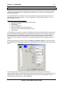
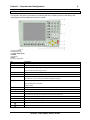
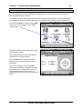
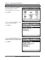
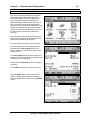
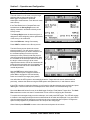
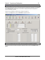
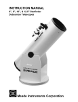
TPS1200 Total Station USER’S GUIDE TPS1200 Total Station USER’S GUIDE Copyright2006 Canary Systems, Inc. All Rights Reserved. tps1200_usersguide.doc Revision A Canary Systems, Inc. 75 Newport Road, Suite 211 New London, NH 03257 USA Voice: (603) 526-9800 Fax: (603) 526-9004 e-mail: [email protected] web: www.canarysystems.com Table of Contents Section 1 Introduction 1.1 Overview........................................................................................ 3 1.2 Features......................................................................................... 4 1.3 Specifications................................................................................. 5 Section 2 Installation 2.1 Tribrach Mounting Platform ............................................................ 6 2.2 Mounting Platform Installation ........................................................ 6 2.3 MCU Installation............................................................................. 7 Section 3 Operation and Configuration 3.1 Hardware Operation Details ........................................................... 8 3.2 Keypad Interface............................................................................ 9 3.3 Operation Details ........................................................................... 10 3.4 Icons .............................................................................................. 11 3.5 Leveling the Instrument.................................................................. 12 3.6 Units Configuration ........................................................................ 14 3.7 EDM & ATR Configuration ............................................................. 15 3.8 Search Windows Configuration ...................................................... 16 3.9 Instrument Azimuth Configuration .................................................. 18 3.10 Acquiring Initial Target Positions .................................................. 20 3.11 MultiLogger Software Configuration ............................................. 21 3.12 Insite Software Configuration ....................................................... 24 Section 4 Maintenance and Troubleshooting 4.1 Maintenance .................................................................................. 25 4.2 Troubleshooting ............................................................................. 26 TPS1200 Total Station User’s Guide Section 1 - Introduction 1.1 Overview Congratulations on your purchase of a Leica TPS1200 series Total Station. With the integration of the MultiLogger software interface and use of the Campbell Scientific CR1000 MCU to automate measurements a very easy-to-use yet high precision site monitoring system can be deployed. This User’s Guide will be your guide to obtain the precision results that are typical in the use of this instrument. Please consult the following guides for additional information in the use and care of your Leica Total Station. Leica TPS1200 User Manual Leica TPS1200 Field Applications Manual Leica TPS1200 System Field Manual TPS1200 Total Station User’s Guide 3 Section 1 - Introduction 4 1.2 Features The TPS1200’s precision angle-measurement system operates continuously providing instant horizontal and vertical circle readings that are automatically corrected for any “out of level” by a centrally located twin-axis compensator. The coaxial EDM uses an infrared laser, has various measuring modes, and measures to prisms and reflective tape. The range is excellent – 3 km to a single prism – and the accuracy superb – 2 mm + 2 ppm. Resolution is 0.1 mm. Following are a few of TPS1200 features: Fast, continuous, high-accuracy angle measurements Accuracy of 1 second No initialization Twin-axis compensator EDM with standard, fast and tracking modes Long range, fast measurements and high accuracy Totally reliable The TPS1200 also includes Power Search. PowerSearch finds reflectors within seconds no matter where they are. With Power-Search activated, TPS1200 rotates and sends out a vertical laser fan. As soon as the fan strikes a prism TPS1200 stops rotating, ATR takes over and fine points – all fully automatically. Use PowerSearch for the first ATR measurement or to find the reflector again if Automatic Target Tracking loses lock completely. PowerSearch is particularly advantageous when operating with remote control. MultiLogger beginning with version 4.0.2 has a Configure Total Station Targets form which automates the programming of the CR800/850/1000 MCU to locate targets and record data. A sample view is shown below. Section 3 of this Users Guide will provide detailed instructions on configuring the Total Station, configuring MultiLogger to record target data and configuring Insite to produce movement data. Up to 100 targets may be configured and up 5 Total Stations may be connected to each CR1000 MCU. Up to 3 Total Stations may be connected to each CR800/850. TPS1200 Total Station User’s Guide Section 1 - Introduction 5 1.3 Specifications We recommend the 1201 series instruments. The TCA1201, TCP1201, TCRA1201 or TCRP1201 are all compatible instruments. Angle Measurement Accuracy Hz, V 1’’ Display resolution (standard deviation, ISO 17123-3): 0.1’’ (0.1 mgon) Method: absolute, continuous, diametrical Compensator Working range: 4’ (0.07 gon) Setting accuracy: 0.5’’ (0.2 mgon) Method: centralized dual axis compensator Distance Measurement (average atmospheric conditions) Range Round prism (GPR1): 3000 m Range 360° reflector (GRZ4): 1500 m Range Mini prism (GMP101): 1200 m Shortest measurable distance: 1.5 m Accuracy (standard deviation, ISO 17123-4): Standard mode: 2 mm + 2 ppm Measurement Time: ~ 1.5 s Display resolution: 0.1 mm Method: Phase measurement (coaxial, invisible infrared laser) Motorized Maximum rotating speed: 45° / s Automatic Target Recognition (average atmospheric conditions) Range ATR mode / LOCK mode Round prism (GPR1): 1000 m / 800 m Range ATR mode / LOCK mode 360° reflector (GRZ4): 600 m / 500 m Range ATR mode / LOCK mode Mini prism (GMP101): 500 m / 400 m Shortest measurable distance: 1.5 m / 5 m Accuracy / Measurement time Positioning accuracy: < 2 mm Measurement time: 3 – 4 s Maximum speed (LOCK mode) Tangential (standard mode): 5 m / s at 20 m, 25 m / s at 100 m Radial (tracking mode): 4 m / s Method: Digital image processing (laser beam) Telescope Magnification: 30 x Free objective aperture: 40 mm Field of view: 1°30’ (1.66 gon) / 2.7 m at 100 m Focusing range: 1.7 m to infinity Keyboard and Display Display: 1/4 VGA (320*240 pixels), graphic LCD, illumination, touch screen (optional) Keyboard: 34 keys (12 function keys, 12 alphanumeric keys), illumination Angle display: 360° ’ ’’, 360° decimal, 400 gon, 6400 mil, V% Distance display: meter, int. ft, int. ft/inch, US ft, US ft/inch Position: face I standard / face II optional Physical Total station weight: 4.8 – 5.5 kg Operating temperature range: –20°C to +50°C Storage temperature range: –40°C to +70°C Dust / water (IEC 60529): IP54 Humidity: 95%, non-condensing TPS1200 Total Station User’s Guide Section 2 - Installation 6 2.1 Tribrach Mounting Platform The Leica Total Station and GPR Reference Targets both install on the Leica GDF21 Tribrach, this is a 3 point mounting bracket which is secured using a 5/8”-11 x 1” bolt threaded up through the bottom of a mounting plate. Following is a suggested method for creating an assembly that can be installed in a concrete pad or tube. It consists of a 20” length of 6” pipe slotted for interior access with an 8” round plate welded to the top. The top plate has a 5/8” hole drilled in the center for installation of the thumbscrew. Use materials suitable to the installation. See drawing below. 8” Leica GDF21 Tribrach 6” Round plate welded to top of pipe NOTE: Drill 5/8” hole in center for bolt 5/8”-11 SS bolt with washer 8” 5” Slot cut in pipe to access thumbscrew 20” 8” 2.2 Mounting Platform Installation To install the mounting fixture securely, form a concrete pad at least 12” deep and sink the assembly up to the bottom of the access slot, 8” deep. For the Total Station use a 12’ length of 12” Sonotube buried at least 8’ deep (or deeper depending on site soil conditions) and filled with concrete. A similar arrangement using Sonotube can also be used for mounting the reference target platform. Any movement of these platforms will directly show as measurement error therefore care must be taken with installation to achieve very stable platforms. Reference Target Installation Total Station Installation Concrete Pad (12” x 24”) TPS1200 Total Station User’s Guide 12” Sonotube (4’ Above Ground 8’+ Below Ground) Section 2 - Installation 7 2.3 MCU Installation The Total Station is automated by using a CR800/850 or CR1000 MCU. The CR800/850 provide 2 TTL RS-232 ports and a single standard RS-232 port which may be used to connect to the Total Station. The CR1000 provides 4 TTL RS-232 ports and a single standard RS-232 port for connecting to the Total Station. Usually the standard RS-232 is used for connecting to the Total Station. Contact Canary Systems for application assistance with using the TTL RS-232 ports. The instructions below will apply to using the standard RS-232 port. Other communication devices may also be used to extend the distance between the MCU and the Total Station. Contact Canary Systems for information on the short haul modems, wireless modems and other options. 1. Install the MCU enclosure. Note the mounting hole dimensions shown on the diagram. The tabs for the enclosure usually have to be installed using the supplied kit. 2. Install the AC Adaptor for the MCU. The connections terminate at the terminal block to the right of the battery. The striped lead on the charger terminates at the CH+ terminal, the other lead at the GND terminal. 3. Install the MCU earth ground. This should be a low-resistance path to earth to provide lightning protection to the MCU. If necessary verify using an earth ground tester. 4. Connect the RS-232 cable to the MCU panel as shown in the diagram. Connect the other end to the null-modem adaptor or the appropriate communication peripheral. Note: When directly connecting the MCU to the Total Station the cable supplied will be a null-modem type, no additional adaptor will be required. 5. Insert the Y cable into the base of the Total Station. The cable terminates with a 9-pin DB-9 for the RS-232 and a Lemo for the AC adaptor. Connect the AC Adaptor to the Y cable Lemo and to AC power. Connect the RS-232 to the null-modem adaptor or to the appropriate communication peripheral. Note: When directly connecting the MCU to the Total Station the cable supplied will be a null-modem type, no additional adaptor will be required. 6. Connect the MCU communications peripheral, if using a COM210 phone modem then connect the phone, if using a NL100 Network Link Adaptor then connect the 10-BASE-T cable. MCU ENCLOSURE 255 mm (10”) BATTERY CR1000 380 mm (15”) WIRELESS WIRELESS RS-232 CSI I/O BLACK=LEICA Y CABLE Up to 30km (20 miles) COM210 or NL100 SHORT HAUL SHORT HAUL Up to 8km (5 miles) DIRECT CABLE GLANDS or CONDUIT FITTINGS BLUE=MCU RS-232 CABLE Null-Modem Up to 100m (300’) ORANGE=LEICA RS-232 CABLE GREEN=LEICA POWER CABLE AC AC ADAPTOR EARTH RED=POWER CABLES AC ADAPTOR AC ADAPTOR TPS1200 Total Station User’s Guide Section 3 – Operation and Configuration 8 3.1 Hardware Operation Details The TPS1200 is turned on by pressing the ON button. The Total Station will run off the internal battery or the AC Adaptor. For permanent installations a Y cable will be supplied that provides for the RS-232 connection and the AC Adaptor connection. The internal battery IS NOT charged by the AC Adaptor but should be left in the unit when installed permanently. It is a good idea to first familiarize yourself with the controls of the TPS1200. See the following depictions for more detail. Note: The second keypad is optional. Front View Rear View TPS1200 Total Station User’s Guide Section 3 – Operation and Configuration 3.2 Keypad Interface The keypad is the primary mechanism for interfacing with the TPS1200 to perform initial testing and configuration as well as obtaining initial survey results. a) Hot keys F7-F12 b) Alphanumeric keys c) CE, ESC, USER, PROG d) ENTER e) Arrow keys f) SHIFT g) Function keys F1-F6 Key Description Hot keys F7-F12 User definable keys to execute commands or access chosen screens. Alphanumeric keys To type letters and numbers. CE Clears all entry at the beginning of user input. Clears the last character during user input. ESC Leaves the current menu or dialog without storing changes made. USER Calls the user defined menu. PROG (ON) If the instrument is off: to turn instrument on. If the sensor is on: press at any time to select an application program. ENTER Selects the highlighted line and leads to the next logical dialog/menu. Starts the edit mode for edit fields. Opens a list box. SHIFT Changes between the first and the second level of function keys. Arrow keys Move the focus on the screen. Function keys F1-F6 Correspond to the six softkeys that appear on the bottom of the screen when the screen is activated. PROG plus USER Turns instrument off. Note: You must at the main menu to turn the unit off. SHIFT F12 Calls STATUS Level & Laser Plummet. SHIFT F11 Calls CONFIGURE Lights, Display, Beeps, Text, Lights page. SHIFT USER Calls QUICK SET Change Settings to: SHIFT Pages up. SHIFT Pages down. TPS1200 Total Station User’s Guide 9 Section 3 – Operation and Configuration 10 3.3 Operation Details The LCD display provides status and navigation information relating to the function of the unit. Once powered on the main menu will display. Additional information on these screen elements is below. Element Time Caption Title Screen area Message line Icons ESC CAPS SHIFT icon Quick coding icon Softkeys Scroll bar Description The current local time is shown. Shows location either in Main Menu, under PROG key or USER key. Name of the screen is shown. The working area of the screen. Messages are shown for 10 s. Shows current status information of the instrument. Refer to "3.4 Icons". Can be used with touch screen. Can be used with touch screen. Same functionality as the fixed key ESC. The last operation will be undone. The caps mode for upper case letters is active.The caps mode is activated and deactivated by pressing UPPER (F5) or LOWER (F5) in some screens. Shows the status of the SHIFT key; either first or second level of softkeys is selected. Can be used with touch screen and has the same functionality as the fixed key SHIFT. Shows the quick coding configuration. Can be used with touch screen to turn quick coding on and off. Commands can be executed using F1-F6 keys. The commands assigned to the softkeys are screen dependent. Can be used directly with touch screen. Scrolls the screen area up and down. The user interface is operated either by the keyboard or by the touch screen with supplied stylus. The workflow is the same for keyboard and touch screen entry, the only difference lies in the way information is selected and entered. Note: To lock the keyboard press and hold SHIFT for 3 s. The message ’Keyboard locked’ is momentarily displayed on the Message Line. To unlock the keyboard press and hold SHIFT for 3 s. The message ’Keyboard unlocked’ is momentarily displayed on the Message Line. Note: The TPS1200 can only be powered down from the main menu. Make sure when automating the TPS1200 using MultiLogger and the CR800/850/1000 that the unit is left powered down or at the main menu, otherwise the automation will not be able to turn power off as needed. TPS1200 Total Station User’s Guide Section 3 – Operation and Configuration 11 3.4 Icons The icons at the top right portion of the display describe the current status of the TPS. More detail is below. Icon Description ATR/LOCK/PS The currently active ATR/LOCK/PS settings or searches are displayed. Reflector The currently active reflector is displayed. EDM The currently active EDM measurement settings are displayed. Compensator/face I&II Compensator off, out of range or face I&II icon is displayed. RCS RCS settings are displayed. Bluetooth The status of each Bluetooth port and any Bluetooth connection is displayed. Line/area The number of lines and areas currently open in the active job is displayed. CompactFlash The status of the CompactFlash card and internal memory if fitted are displayed. card/internal memory • For the CompactFlash card, the capacity of used space is shown in seven levels. • For the internal memory if fitted, the capacity of used memory is shown in nine levels. Battery The status and source of the battery is displayed. The percentage of remaining power capacity for all batteries are displayed numerically and graphically. For internal and external battery being attached at the same time the internal battery is used until it is empty and then the external battery is used. SHIFT The status of the SHIFT key is displayed. Quick coding Shows the quick coding configuration. Can be used with touch screen to turn quick coding on and off. TPS1200 Total Station User’s Guide Section 3 – Operation and Configuration 12 3.5 Leveling the Instrument It is very important to level the instrument after installing it. If the Total Station is not leveled correctly measurements will not be obtained. The bubble level above the keyboard can be used to make the major adjustment, use the thumbscrews on the tribrach to locate the bubble in the center. The fine adjust must be done using the Total Station. First, press the SHIFT key. After pressing SHIFT arrow in the lower right portion of the display should be solid. Then press <F12>. This will display the Level & Laser Plummet screen. Use the thumbscrews to locate the bubble as precisely in the center as possible. Note the CONT button at the bottom of the display. Use the stylus to select the button or press <F1>. Note: The circular level on the Total Station should also be adjusted to match the electronic level. See section 5.5 (page 106) of the Leica TPS1200 User Manual for instructions on adjusting the circular level using the supplied hex wrench. TPS1200 Total Station User’s Guide Section 3 – Operation and Configuration 13 3.6 Units Configuration After leveling the instrument the various settings related to the acquisition of targets should be checked. First set the units to Decimal Degrees. This is preferable because then the units will match the MultiLogger Total Station configuration entries. Unfortunately the TPS1200 series Total Stations do not allow display of radians, which are the default data units for MultiLogger. Select the Config menu from the main menu. Press <ENTER>. Scroll down to General Settings (or press the number key 3). Press <ENTER>. Scroll down to Units & Formats (or press the number key 3). Press <ENTER>. TPS1200 Total Station User’s Guide Section 3 – Operation and Configuration The default options for Units & Settings will display. Scroll down to Angle Unit. Press <ENTER> to display the list of options. Select 360º dec. Press <ENTER>. The option should be shown selected. Press CONT to return to the main menu. TPS1200 Total Station User’s Guide 14 Section 3 – Operation and Configuration 3.7 EDM & ATR Configuration Next, check the EDM and ATR configuration options and adjust them if necessary. Select the Config menu from the main menu. Press <ENTER>. Scroll down to Instrument Settings (or press the number 2 on the numeric keypad). Press <ENTER>. The first option EDM & ATR Settings should be selected, if not then use the scroll keys to select it (or press the number 1 on the numeric keypad). Press <ENTER>. TPS1200 Total Station User’s Guide 15 Section 3 – Operation and Configuration The defaults are shown at right. Make sure Reflector (IR) is configured as the EDM Type. Make sure the correct Reflector is selected for the survey to be conducted. Check the other settings including EDM Mode, Automation and ATR Settings to make sure they match the screenshot shown at right. The default settings are shown, adjust as needed. Use Leica Circ Prism for the GPH1 Reference Prism and the GPR112 Target Prism, press <ENTER> with Reflector selected to display the list of available types. Press CONT when finished configuring the Reflector type. Press CONT at the EDM & ATR Settings screen to save the settings and return to the main menu. 3.8 Search Windows Configuration Next, check the Search Windows configuration and adjust if necessary. Select the Config menu from the main menu. Press <ENTER>. Scroll down to Instrument Settings (or press the number 2 on the numeric keypad). Press <ENTER>. TPS1200 Total Station User’s Guide 16 Section 3 – Operation and Configuration Scroll down to Search Windows (or press the number 2 on the numeric keypad). Press <ENTER>. Make sure that PowerSearch is Off. Press PAGE to change to the ATR Window page. Configure the Hz (horizontal) and V (vertical) dimensions in degrees for the ATR Window. Generally 5º is adequate to provide a reasonable search range while keeping the likelihood of acquiring the wrong target low. Press CONT when finished to return to the main menu. TPS1200 Total Station User’s Guide 17 Section 3 – Operation and Configuration 3.9 Instrument Azimuth Configuration One of the most important steps in configuring and initializing the instrument is setting the Instrument Azimuth, or the zero azimuth. This step is designed to provide a reference for subsequent target measurements at the site, it also is used when replacing the instrument to provide a way to “zero-out” any differences in the angle measurements from one unit to another. It should also be performed periodically to re-zero the instrument to improve its measurement accuracy. Note: Setting the instrument azimuth requires a stable reference platform as measurements are subsequently referenced to this point. From the main menu select the Survey option. If the Total Station has a CompactFlash card installed then the Survey Begin screen will display, otherwise it will advance directly to the Survey screen. The Survey Begin screen is shown at right. It is designed to allow configuring various parameters of the survey to be conducted. Double-check the Reflector selection, change if necessary. Press CONT to advance to the Survey screen. Note the SETAZ button on the bottom of the display. Use the stylus to select this button or press the <F5> button to advance to the SETAZ screen. TPS1200 Total Station User’s Guide 18 Section 3 – Operation and Configuration Point the telescope at the reference prism. Use the crosshair spotting tool at the top of the telescope to more precisely locate the reference or view the prism through the telescope itself. Align the crosshairs of the telescope with the center of the target. It does not have to be an exact alignment because the ATR of the instrument will locate the prism precisely once it’s engaged. Note the DIST button at the bottom of the SETAZ screen. Use the stylus to select this button or press <F2> to engage the ATR and actively locate and measure the reference target position. The Azimuth and Horiz Dist fields should update after acquiring the target. If the ATR is unable to locate the reference you will need to sight the telescope more precisely and press <F2> again. If unsuccessful after a few attempts then check section 4 for troubleshooting help. Note the Az=0 button at the bottom. Use the stylus or press <F4> to set the Azimuth to 0. The Azimuth should update to 0.0000 (or thereabouts). Note the SET button on the bottom of the display. Use the stylus to select the button or press <F1> to set the Azimuth. Confirmation for setting the Station and Orientation will display. Note the OK button at the bottom. Use the stylus to select the button, or press <F4> to return to the Survey screen. The Survey screen can be used to acquire target positions or press ESCAPE to return to the main menu. TPS1200 Total Station User’s Guide 19 Section 3 – Operation and Configuration 20 3.10 Acquiring Target Positions The total station must be used to acquire target positions that are then entered into the MultiLogger configuration to automate subsequent measurements. From the main menu select Survey. If the Total Station has a CompactFlash card installed then the Survey Begin screen will display, otherwise it will advance directly to the Survey screen. The Survey Begin screen is shown at right. It is designed to allow configuring various parameters of the survey to be conducted. Check the Reflector, change if necessary. Press CONT to advance to the Survey screen. The initial Survey screen shows the current telescope position. You will need to point the telescope at the prism you wish to measure. Use the crosshair spotting tool at the top of the telescope to more precisely locate the prism or view the prism through the telescope itself. Align the crosshairs of the telescope with the center of the target. It does not have to be an exact alignment because the ATR of the instrument will locate the prism precisely once it’s engaged. Use the knobs on each side for fine horizontal and vertical adjustments. Note the DIST button at the bottom of the display. Use the stylus to select this button or press <F2> to engage the ATR and actively locate and measure the target prism position. Auto will utilize the ATR system to automatically locate the Target within the search window defined previously, measure the distance using the EDM system and update the Hz, V and distance values. If the ATR is unable to locate the reference you will need to sight the telescope more precisely and press <F2> again. If unsuccessful after a few attempts then check section 4 for troubleshooting help. Record the Hz and V values for entry in the MultiLogger Configure Total Station Targets form. The Horiz Dist measurement value can also be recorded but it is not used for configuring the automation. To acquire the next target simply move the telescope, aim it and press DIST again. The ATR will engage to locate the new target precisely and new measurements will be taken and displayed. It’s a good idea to view the targets through the telescope to make sure the correct target has been acquired. If targets are spaced closely together it’s possible that the ATR acquires the wrong target. When finished press ESCAPE to return to the main menu and power the unit down. TPS1200 Total Station User’s Guide Section 3 – Operation and Configuration 21 3.11 MultiLogger Software Configuration MultiLogger beginning with version 4.0.2 provides support for configuring the Total Station. It is supported by the CR800/850/1000 Control Modules. You will need to configure your Network Configuration to include a CR800/850 or CR1000. Double-click the CR800/850 or CR1000 node to display the Logger form. Advance to the Program tab to view the Total Station configuration button. Note: If the Total Station button is NOT visible contact Canary Systems for application assistance. You may also access the Configure Total Station Targets form with the menu item Configure | Total Station. TPS1200 Total Station User’s Guide Section 3 – Operation and Configuration The Configure Total Station Targets form is shown at right. To navigate among the targets use the list on the left side of the screen. Up to 100 targets can be configured. Configure each Target using the options on the right side of the form. The buttons on the form have the following functions: To display the Configure Total Station Targets help topic from the Help file. To accept all the changes made to the Total Station configuration. To cancel all the changes made to the Total Station configuration. The controls have the following functions: Label – Enter up to 24 alpha-numeric characters can be entered to describe the name for the Target. Note however that 4 values are stored per Target, this includes the horizontal and vertical angles (in radians), the distance (in meters) and the status code. These values are described by using the Label name with the addition of “_H”, “_V”, “_D” and “_S” suffixes. For example, see the screenshot at right of how the labeling for the first 3 Targets was configured once they were enabled. TPS1200 Total Station User’s Guide 22 Section 3 – Operation and Configuration 23 Description – Enter up to 256 characters to describe the Target in greater detail. This may include reference or location information or useful details regarding the Target. Model – Select the type of Total Station that will be used to acquire the Target positions. Targets are enabled by configuring the Model, i.e. if left at ‘None’ then it will be disabled. Press the Model button to display additional information about the selection. Press the gear button to display the instruction file used to acquire the Target position. Target Type – Configure the type of Target to be acquired. Units – Configure the units of the values to be entered for the Target Position and Search area. The default selection of Radians matches the output units however Decimal Degrees are preferable as they correspond directly with the display of the Total Station. H Position – Enter the horizontal position of the Target. The Total Station will search at this location and then plus or minus the corresponding H Search value. Enter the Target position as precisely as possible to avoid errors due to the Total Station acquiring the wrong Target. Units must match the Units setting. V Position – Enter the vertical position of the Target. The Total Station will search at this location and then plus or minus the corresponding V Search value. Enter the Target position as precisely as possible to avoid errors due to the Total Station acquiring the wrong Target. Units must match the Units setting. H Search – Enter the horizontal Search area for Target location. Enter a value that will provide a compromise between the need to give the Total Station a workable area to look for the Target and the need to make sure the correct Target is selected. Units must match the Units setting. V Search – Enter the vertical Search area for Target location. Enter a value that will provide a compromise between the need to give the Total Station a workable area to look for the Target and the need to make sure the correct Target is selected. Units must match the Units setting. Averaging – Configure the number of samples to acquire per measurement. It takes approximately 1 second per sample so consider this as it relates to the overall scan frequency required for the project. Generally the Averaging should be left at 1 or a low number and if the data indicates a need for improved stability utilize this option. Auto Relocate – Check this option to instruct the Total Station to use the last measurement as the positional data for the next measurement. This is typically selected for Targets that are moving at a significant rate. Last Target – Check this option if this is the last Target to be acquired. This will locate the telescope in its protected position and shut down the Total Station to conserve power. Note: Once the target positions have been configured press Accept to save the changes and return to the Logger form. You will need to press Update to build the automation program and download it to the MCU. The new targets will not be acquired by the MCU until the Update function is run. TPS1200 Total Station User’s Guide Section 3 – Operation and Configuration 24 3.12 Insite Software Configuration The collected data consists of 4 values, the Horizontal (H) and Vertical (V) angles in radians, the Distance (D) in meters and the Status. See section 4.2 for more information on the Status codes. Using the formulas described below the angles and distance can be transformed into simple coordinates that can provide movement data in any angle. You will need to construct 6 Calculated Elements to perform these conversions. The examples shown below assume the default Target labels for Target 1 are used. Conversion to simple coordinates: TARGET_1_XC = D100@TARGET_1_D*SIN(D100@TARGET_1_H/3.14159265*180)*SIN(D100@TARGET_1_V/3.14159265*180) TARGET_1_YC = D100@TARGET_1_D*COS(D100@TARGET_1_H/3.14159265*180)*COS(D100@TARGET_1_V/3.14159265*180) TARGET_1_ZC = D100@TARGET_1_D*COS(D100@TARGET_1_V/3.14159265*180) Where; TARGET_1_XC = Coordinate data parallel to instrument. TARGET_1_XY = Coordinate data perpendicular to instrument. TARGET_1_ZC = Coordinate data vertical to instrument (height). Conversion to movement including azimuth correction: TARGET_1_XD = (TARGET_1_XC – TARGET_1_XCI) * COS(ANGLE) TARGET_1_YD = (TARGET_1_YC – TARGET_1_YCI) * COS(ANGLE) TARGET_1_ZD = TARGET_1_ZC – TARGET_1_ZCI Where; TARGET_1_XCI = The X coordinate data calculated from the initial target data. TARGET_1_YCI = The Y coordinate data calculated from the initial target data. TARGET_1_ZD = The Z coordinate data calculated from the initial target data. ANGLE = The azimuth angle. TPS1200 Total Station User’s Guide Section 4 – Maintenance and Troubleshooting 25 4.1 Maintenance The TPS series instruments are designed to provide years of reliable and trouble-free operation. They are rated IP54 dust and water resistant but when deployed for long-term monitoring out-of-doors must be protected by a suitable glass faced enclosure. Contact Canary Systems for information on available enclosures. Note: When transporting the instrument ALWAYS use the provided carry-case. The battery should also be removed from the instrument and stored in its compartment in the carry-case. The battery should be installed in the total station at all times to maintain correct balance and optimum measurement accuracy. Note the following directions for maintaining the function of the instrument and it’s peripherals: Battery The internal battery IS NOT charged by the external AC Adaptor. It must be removed and placed in its charging cradle to be charged. The battery should be removed every 3 months to be charged. It will operate the instrument for 6-8 hours (operation time) in the even to AC power loss. Objective, eyepiece and prisms They should be periodically checked and cleaned. Dust may be blown off the lenses and prisms with compressed air. Do not use your fingers to clean off the glass. If cleaning is necessary use only a clean, soft, lint-free cloth moistened with water or alcohol. Do not use other liquids, they are unnecessary and can damage the glass or other polymer components. Instrument enclosure The instrument enclosure should be periodically checked for dust, water or water staining. Wipe dust or water stains with a clean, soft, lint-free cloth moistened with soap and water or alcohol. Excess water on the outside of the enclosure will degrade the instrument function so it is important to keep water off the glass or to construct a cover or other suitable protection for the instrument. Cables and plugs All cables and plugs must be kept dry for proper operation and to avoid corrosion or degradation of the contacts. If the cables, plugs or associated wiring becomes wet then remove from service and dry before re-installing. Factory Cleaning and Recalibration The total station should be removed from service at least once per year and returned to the factory for service. This includes cleaning and re-calibration. Contact Canary Systems for information on available service and support programs. TPS1200 Total Station User’s Guide Section 4 – Maintenance and Troubleshooting 26 4.2 Troubleshooting The common errors or problems will be described with suggested remedial action. Error: Unit does not power up. Check that the AC Adaptor is plugged in and power is available. To confirm instrument function try operating it from the internal lithium-ion battery. If the unit was in service for an extended period of time the internal battery may require charging. Error: “Prism Not Found” displays during target acquisition or Distance reads 0. This may be the result of incorrect target or instrument position or interference with the targeting light beam. Use the telescope on the instrument to visually obtain the target, then try again. If unsuccessful check that the enclosure is clean and there are no obvious blemishes that may be causing interference. Check whether the target prisms require cleaning. Water on the surface of the prisms doesn’t generally affect the measurements. Atmospheric conditions including heavy rain and fog will also affect the ability of the instrument to accurately acquire target positions. See the additional information on the following page. Error: Status codes returned by automation system are not 0. The measurement status codes returned by the CR800/850/1000 provide status information regarding the measurements including error codes if the measurements fail. If the instrument obtains the best quality angular and distance measurement the code returned will be 0. Following is a complete list of the codes and their explanation. Code 0 8 12 1283 1284 1285 1288 1289 1290 1291 1292 1293 8710 Description Measurements successful. Measurements were aborted. This code should never be returned. System was powered off. This code should never be returned. Measurements are valid but there was an error applying corrections. The two errors involve the ATR system and the inclination correction. Measurements were successful, however the accuracy could not be guaranteed. Angular measurements were successful, however Distance could not be guaranteed. See Prism Not Found error above and suggested remediation. Angular measurements were successful, however Distance could not be measured. See Prism Not Found error above and suggested remediation. Only the angular measurements are available but accuracy cannot be guaranteed. Angle of inclination measurement error. Check leveling and stability of instrument. See section 3.5 for more information. Check whether tilt compensator is enabled. Distance measurement could not be obtained because of incorrect EDM settings. See section 3.7 for more information. No measurements because of missed target point. See Prism Not Found error above and suggested remediation. Verify coordinates entered for target. Instrument was busy when measurements were requested. Target could not be found. See Prism Not Found error above and suggested remediation. Verify coordinates entered for target. Error: Angular or Distance measurement values returned are -99999. This error code is returned when no communication between the CR800/850/1000 and Total Station was possible, either due to a power problem at the instrument or a communication problem. Check power and all communication cabling. If using a short-haul modem or other communication extender try replacing one or both units to restore the communications. TPS1200 Total Station User’s Guide Section 4 – Maintenance and Troubleshooting 27 Error: I can’t see the crosshairs of the telescope anymore. Notice the telescope has an eyepiece (smaller inner knob) and focus (larger outside knob) adjustment knobs. See the Rear View illustration in section 3.1 for detail. Notice the infinity indicator on the focus adjustment ring. Turn the telescope focus all the way to infinity. Then adjust the eyepiece focus to reacquire the crosshairs. Error: The instrument won’t let me use the adjustment knobs to locate another target. This occurs because the Total Station is in LOCK mode or EDM Mode is setting to tracking. The easiest way to turn LOCK mode off is from the Survey screen. Press the <SHIFT> key, then press <USER>. This will display the Quick Set screen. If LOCK mode is on then Turn OFF will be shown to the right of LOCK. Use the stylus to toggle the LOCK mode or use the cursor <DOWN> key to move down and then press <ENTER>. Check the EDM Mode, if set to Standard then it should show Change to TRK. Adjust if needed. The correct settings are shown in the screenshot. You will be returned to the Survey screen after changing any settings. Press <ESCAPE> to return to the Survey screen without changing settings. Error: The telescope is not moving at all to find a target after pressing DIST in the Survey screen. This usually occurs because the ATR mode is off. The easiest way to turn ATR mode on is from the Survey screen. Press the <SHIFT> key, then press <USER>. This will display the Quick Set screen. If ATR mode is off then Turn ON will be shown to the right of ATR. Use the stylus to toggle the ATR mode or press <ENTER>. You will be returned to the Survey screen after changing any settings. Press <ESCAPE> to return to the Survey screen without changing settings. TPS1200 Total Station User’s Guide