1
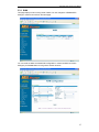
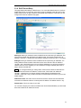
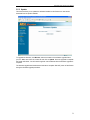
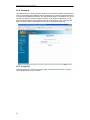
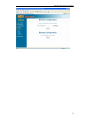
BEST DATA PRODUCTS, INC.
DSL542EU & DSL582E
ADSL2/2+ Router Modem
User ’s Manual
Revision 2.0
October 2004
DSL542EU ADSL Router User’s Manual
Copyright
This manual may not be copied, photocopied, transmitted, or translated into language or
computer language, in any form, or by any means, in whole or in part, without the prior written
consent by the manufacturer.
© Copyright 2004 All rights reserved.
Disclaimer
The manufacturer makes no representations or warranties, expressed, statutory or implied,
regarding the fitness or merchantability of this product for any particular purpose. Further, the
manufacturer is not liable for any damages, including but not limited to, lost profits, lost saving,
or other incidental or consequential damages arising out of the use of this product. The
manufacturer also reserves the right to make any improvements or modifications to the product
described in this manual at any time, without notice of these changes.
i
DSL542EU ADSL Router User’s Manual
Federal Communications Commission (FCC) NOTICE
This equipment has been tested and found to comply with the limits for a Class B
digital device, pursuant to Part 15 of FCC Rules. These limits are designed to
provide reasonable protection against harmful interference in a residential installation.
This equipment generates uses and can radiate radio frequency energy and, if not
installed and used in accordance with the instructions, may cause harmful
interference to radio communications. However, there is no guarantee that
interference will not occur in a particular installation. If this equipment does cause
harmful interference to radio or television reception, which can be determined by
turning the equipment off and on, the user is encouraged to try to correct the
interference by one or more of the following measures:
z Reorient of relocate the receiving antenna.
z Increase the separation between the equipment and receiver.
z Connect the equipment into an outlet on a circuit different from that to which the
receiver is connected.
z Consult the dealer or an experienced radio / TV technician for help.
This unit was tested with shielded cables on the peripheral devices. Shielded cables
must be used with the unit to insure compliance. This statement can be deleted if
unit was not tested with shielded cables.
The manufacture is not responsible for any radio or TV interference caused by
unauthorized modifications to this equipment. Such modifications could void the
user's authority to operate the equipment.
This device complies with Part 15 of the FCC rules. Operation is subject to the
following two conditions:
1. This device may not cause harmful interference.
2. This device must accept any interference that may cause undesired operation.
CAUTION
Always disconnect all telephone lines from the wall outlet before servicing or
disassembling this equipment.
IMPORTANT SAFETY INSTRUCTIONS
When using your telephone equipment, basic safety precautions should always be followed to
reduce the risk of fire, electric shock and injury to persons, including the following;
1. Do not use this product near water, for example near a bath tub, wash bowl,
kitchen sink or laundry tub, in a wet basement or near a swimming pool.
2. Avoid using a telephone (other then a cordless type) during an electrical storm.
There may be a remote risk of electric shock from lighting.
3. Do not use the telephone to report a gas leak in the vicinity of the Leak.
4. Use only the power cord and batteries indicated in this manual. Do not dispose of
batteries in a fire. They may explode. Check with local codes for possible special
disposal Instructions.
ii
Table of Contents
1.
INTRODUCTION.................................................................................................1
1.1
1.2
2.
FEATURES ......................................................................................................1
PACKAGE CONTENTS .....................................................................................1
ROUTER OVERVIEW ........................................................................................2
2.1
2.2
PORTS AND BUTTONS ....................................................................................2
LED DESCRIPTION .........................................................................................3
3.
INSTALLING YOUR ROUTER.........................................................................4
4.
HTTP WEB CONFIGURATION........................................................................5
4.1
4.2
5.
QUICK CONFIGURATION .................................................................................5
WIZARD ..........................................................................................................6
ADVANCED CONFIGURATION ....................................................................10
5.1
QUICK START ...............................................................................................10
5.2
INFORMATION ...............................................................................................11
5.2.1
Device Information ..............................................................................11
5.2.2
WAN Information .................................................................................12
5.2.3
LAN Information ..................................................................................12
5.2.4
ADSL Information................................................................................13
5.2.5
DHCP Information...............................................................................13
5.2.6
Route Information ................................................................................14
5.3
CONFIGURATION ..........................................................................................14
5.3.1
WAN .....................................................................................................15
5.3.2
LAN ......................................................................................................19
5.3.3
ADSL ....................................................................................................19
5.3.4
DNS Server...........................................................................................20
5.3.5
SNTP ....................................................................................................20
5.3.6
DHCP Server/Relay .............................................................................21
5.3.7
Routing Table.......................................................................................23
5.3.8
Virtual Server.......................................................................................24
5.3.9
IP Filter................................................................................................25
5.3.10 Port Filter ............................................................................................25
5.3.11 IDS .......................................................................................................26
5.4
TOOLS ..........................................................................................................27
5.4.1
Ping ......................................................................................................27
5.4.2
OAMLoopback .....................................................................................28
5.5
SYSTEM ........................................................................................................29
5.5.1
Save ......................................................................................................29
5.5.2
Restart ..................................................................................................30
5.5.3
Update..................................................................................................31
5.5.4
Password..............................................................................................32
5.5.5
Config File ...........................................................................................32
6.
TROUBLESHOOTING.....................................................................................34
DSL542EU ADSL Router User’s Manual
1.
Introduction
The DSL542EU ADSL Router Modem is an Asymmetric Digital Subscriber Line (ADSL)
Modem for home or small office network connectivity to an Internet service provider over the
Asynchronous Transfer Mode (ATM) network protocol. ATM is a protocol that divides packets
into small fixed sized cells for rapid transmission over high-speed networks. The ATM
protocol allows various types (e.g. data, voice, and video) of traffic to be securely and
efficiently carried over the same network.
This device provides a perfect solution to connect a small group of Internet users to highspeed network via the existing twisted pair telephone line.
A 10/100BaseT port is provided for connection to an Ethernet LAN or Ethernet-equipped PC,
and an ADSL port for connecting to your ADSL service provider to get on the Internet.
1.1
•
•
•
•
•
•
•
•
•
•
•
1.2
Features
Equipped with a 4 or 8-Port 10/100 Ethernet Switch
Connects multiple PCs to the Internet with just one WAN IP Address (when
configured in router mode with NAT enabled)
Configurable through user-friendly web pages
Supports IPSec and PPTP Pass-Through for Virtual Private Network (VPN)
Configurable as a DHCP Server on Your Network
Compatible with virtually all standard Internet applications
Simple web based status page displays a snapshot of your system configuration, and
links to the configuration pages
Downloadable flash software upgrades
Support for up to 8 Permanent Virtual Circuits (PVC)
Supports Classical IP over ATM (CLIP or also referred to as RFC1577)
Supports USB interface for LAN connection (optional)
Package Contents
Carefully unpack and remove the content. Contact your dealer immediately if any of the
following is missing or damaged:
•
•
•
•
•
•
•
DSL542EU ADSL Router Modem
RJ45 Ethernet cable
RJ11 telephone cable
USB cable (Optional)
Quick Installation Guide
Modem Manual/Driver CD
DC power adaptor
Note: Follow all cautions and instructions in this guide to avoid damaging the product.
1
DSL542EU ADSL Router User’s Manual
2.
Router Overview
Your Router has many ports, switches and LEDs. Let’s take a look at the different options.
Depending upon your model of Router, your Router may have some or all of the LEDs and
ports listed below:
2.1
Ports and Buttons
(4 Ports Router)
(8 Ports Router)
RESET: The RESET button will set the Router to its factory default setting and reset the
Router. You may need to reset the Router to its factory defaults if the configuration is
changed, you loose the ability to enter the Router via the web interface, or following a
software upgrade, and you loose the ability to enter the Router. To reset the Router, simply
press the reset button for more than 5 seconds. The Router will be reset to its factory defaults
and after about 20-30 seconds the Router will become operational again.
DC 9V: Connect the power adapter that came with the Router. Using a power supply with a
different voltage rating will damage this product. Make sure to observe the proper power
requirements. The power requirement is 9 volts.
LAN (Local Area Network) 1-4 or 1-8: Connect to Ethernet network devices, such as a PC,
hub, switch, or router. Some Routers come with four LAN ports and some come with eight
LAN ports.
USB (Universal Serial Port) (optional): Connects this port to a PC’s USB port. The Router
only supports Window’s based PCs via an RNDIS driver (included in the software).
ADSL: This is the WAN interface which connects directly to your phone line.
2
DSL542EU ADSL Router User’s Manual
2.2
LED Description
(4 Ports Router)
(8 Ports Router)
POWER: The LED stays lighted to indicate the system is power on properly.
LINK: The LED stays lighted to indicate the WAN connection is established.
DATA: The LED flashes to indicate the Router is sending/receiving data.
LAN 1-4 or 1-8: The LED stays lighted when a connection is established to LAN port and
flashes when LAN port is sending/receiving data. (The number of LAN ports depends on your
model.)
USB (optional): The LED is lighted when a connection is established to USB port and flashes
when USB port is sending/receiving data.
3
DSL542EU ADSL Router User’s Manual
3.
Installing Your Router
The Figure below illustrates the hardware connections. Refer to the steps that follow for
specific instructions.
Before you begin, turn the power off for all devices. These include your
computer(s), your LAN hub/switch (if applicable), and the DSL542EU ADSL
Router.
WARNING
Step 1. Connect the ADSL cable
Connect one end of the provided phone cable to the port labeled ADSL on the rear panel of
the device. Connect the other end to your wall phone jack.
Step 2. Connect the Ethernet cable.
Attach one end of a provided Ethernet cable to a PC and the other to the LAN port on the rear
panel of Router.
Step 3. Attach the power connector.
Connect the AC power adapter to the power connector labeled DC 9V on the back of the
device and plug in the adapter to a wall outlet or power strip.
Step 4. Power on your system.
Turn on and boot up your computer(s) and any LAN devices such as hubs or switches.
4
DSL542EU ADSL Router User’s Manual
4.
HTTP Web Configuration
The web configuration interface provides an easy-to-use user interface for Router
configuration. All Router configurations can be done through this interface.
Start your favorite web browser (i.e. Netscape 4.0 or Explore 4.0 higher) and then enter the IP
address (default is http://192.168.1.1) in the web page address. The web configuration page
will appear.
4.1
Quick Configuration
The Quick Configuration page displays DSL Line Status, PPP Status, PPP, IP Address of
PPP, and PPP Up Time. Due to the default configuration is RFC1483 Bridge mode, you
cannot do anything at the page. If you need to make some advanced configuration, click the
Advanced Configuration link. A new window appears prompting you for user name and
password needed to gain access the Advanced Configuration page. Use the default user
name: admin and password: admin to login. Refer to chapter 5 for detail description.
5
DSL542EU ADSL Router User’s Manual
4.2
Wizard
Wizard Setup page is a step-by-step guide and it will guide you through quick and basic steps
to help you connect to your ISP (Internet Service Provider). Press Next button and follow the
introduction to complete the configuration procedure. You will be asked to enter some
information to perform the connection. This information should be provided to you by your
ISP.
Step 1. Select a suitable SNTP Server and Time Zone of your location to keep your Router
synchronizes with the time server.
Step 2. Select actual mode that your service provider used.
6
DSL542EU ADSL Router User’s Manual
7
DSL542EU ADSL Router User’s Manual
Step 3. Input ATM VPI/VCI values when you select Bridge mode at previous step. If you
choose PPPoE or PPPoA, you will need to fill user name and password column. If you
choose Routing mode, you need to input WAN IP, Netmask, Gateway and DNS.
Step 4. Summary page displays all parameter you configured ahead to let you reconfirm
these settings are correct.
8
DSL542EU ADSL Router User’s Manual
Step 5. Click Apply button, system will save your configuration to Flash ROM automatically.
9
DSL542EU ADSL Router User’s Manual
5.
Advanced Configuration
To setup your Router with advanced configurations, from the Main page, select Advanced
Configuration. When the configuration utility prompts you to enter the user name and
password, enter the default value admin for both.
5.1
Quick Start
Quick Start page displays the configuration of current Running Mode.
Select the suitable mode for your Router as instructed by your ISP at this page. The Router
supports 1483-Bridged, 1483-Routed, 1577-Routed, PPPoA, PPPoE and NAPT Bridged (also
called MER). After select the mode at drop-down menu, click the Apply and Save button. All
detail settings can edit after applied.
10
DSL542EU ADSL Router User’s Manual
5.2
Information
Information menu provides you with the current status of Device, WAN, LAN and ADSL.
5.2.1 Device Information
This page displays the basic device information including DSP Version, Firmware Version,
CPE-end Interface and MAC address.
11
DSL542EU ADSL Router User’s Manual
5.2.2 WAN Information
This page displays the WAN information including PVC (VPI/VCI), Protocol, WAN IP Address,
NAT and Packets has been sent and received.
5.2.3 LAN Information
This page displays the LAN information including Ethernet IP Address, Link Seed, Broadcast
times, Collisions times and Packets has been sent and received.
12
DSL542EU ADSL Router User’s Manual
5.2.4 ADSL Information
This page displays the ADSL information such as Connected State, Upstream Rate,
Downstream Rate, Standard, Coding Gain, etc.
5.2.5 DHCP Information
This page displays DHCP clients that request IP from DHCP server when DHCP server is
enabled. It shows the DHCP clients information including its IP Address, Computer Name,
MAC Address and Lease Time.
13
DSL542EU ADSL Router User’s Manual
5.2.6 Route Information
This page displays the Routing Table of the Router. The routing table will show the routing
status of Destination, Netmask, Gateway, and Interface.
5.3
Configuration
Configuration menu provides you with a user-friendly interface to configure detail settings of
WAN, LAN, ADSL, DNS Server, SNTP, DHCP Server/Relay, Routing Table, Virtual Server, IP
Filter, Port Filter and IDS (Intrusion Detection System).
14
DSL542EU ADSL Router User’s Manual
5.3.1 WAN
This page displays current running mode of WAN. You can change the ATM/WAN/PPP
settings or create a new mode on the same page.
You can re-edit or delete an existed WAN configuration or create new WAN connection
settings by click Create button to bring out the window as below.
15
DSL542EU ADSL Router User’s Manual
ATM
VPI and VCI: VPI (Virtual Path Identifier) and VCI (Virtual Channel Identifier) are the
identifiers to make a virtual connection. Your ISP will provide them.
WAN IP
If you are a leased line user and have a fixed IP, also called Static IP, you need to enter your
assigned WAN IP, Netmask and Gateway in WAN IP column. This information is provided to
you by your ISP.
NAT: You can enable or disable NAT function and indicate its WAN IP, Netmask and
Gateway.
PPP
Service Name: Some ISP require Service Name to perform the connection. If your ISP
provides it to you, enter it here.
Idle timeout: You may select either Always On or Dial On Demand. When Dial On
Demand is selected, the connection will disconnect if no activity is detected after the specified
Dial On Demand value (in minutes).
Keep alive time: This value specifies the time to check line connection status after
disconnecting from ISP. System will not check line connection if set this value to 0.
Login name and Password: The login name and password are for the connection access.
Your ISP will provide them.
WAN Configuration page provides you to edit running protocols and create multi-PVCs, but
only one routing protocol is supported. After a routing PVC has been created, other PVCs can
only be configured as 1483-Bridged mode. You can create maximum 8 PVCs.
16
DSL542EU ADSL Router User’s Manual
Ethernet Ports Mapping feature allow you map each PVC to four/eight Ethernet ports. You
can assign more than one PVC to one Ethernet port (LAN port), or more than one Ethernet
port (LAN port) to single PVC. But only Ethernet port 1 (LAN 1) can configure the Router if
other Ethernet ports (LAN ports) don’t exist the same Bridge group. Routing mode has
highest priority on port mapping. If the port is assigned for routing mode protocol, you cannot
assign it to other PVCs. After unchecking the routing mode entry, the port will become
assignable.
Please note that every time you add a new PVC or change the PVC/Port Mapping and click
Apply button, switch will reset its settings. That may be a pause between your Network
Interface Card and Router. Sometimes the web page cannot get the response, and return
page not found. If so, click WAN link which locates at left menu after clicking the Apply button
two or three seconds.
DNS Server, SNTP, DHCP Server, Routing Table, Virtual Server, IP Filter, Port Filter and IDS
functions can only be applied to routing protocol ports.
WAN configuration page shows four or eight Ethernet ports (depending on your model)
available for multiple using.
17
DSL542EU ADSL Router User’s Manual
Below shows you when the port 2 (LAN 2) is assigned to both 0/34 and 0/35 PVC. Port 4
(LAN 4) is assigned to PVC4 ~ PVC8. And assign port 3 (LAN 3) nothing.
After assign port 3 (LAN 3) to PVC2, port 2 (LAN 2) and port 3 (LAN 3) belong to the same
group. So the check box of PVC3 will be checked automatically.
18
DSL542EU ADSL Router User’s Manual
5.3.2 LAN
This page displays the current IP Address and Subnet Mask of LAN. You can change the
default LAN IP address and Subnet Mask according to your needs.
5.3.3 ADSL
This page displays ADSL standard and EC/FDM mode. DO NOT change the default settings
of this page unless you have the instruction from the ISP.
19
DSL542EU ADSL Router User’s Manual
5.3.4 DNS Server
This page displays the configured IP address of DNS (Domain Name Services) server(s).
Enter the IP address when DNS Server is assigned by the ISP.
5.3.5 SNTP
This page displays the settings of SNTP (Simple Network Time Protocol). It allows you to
configure SNTP server location and some parameter to synchronize correct time. You can
also use system clock on your own computer to obtain the time.
20
DSL542EU ADSL Router User’s Manual
5.3.6 DHCP Server/Relay
This page displays the settings of DHCP server. You can enable DHCP server for LAN PCs.
DHCP Relay server can be chosen when DHCP server is disabled. Some ISPs perform the
DHCP server function for their customers’ home/small office networks. In this case, you can
configure the Router as a DHCP relay agent.
Starting IP: Starting IP Address is where the DHCP server starts issuing IP addresses. This
value must be greater than the Router’s IP address value. For example if the Router’s IP
address is 192.168.1.1 (default) than the starting IP address must be 192.168.1. 2 (or higher).
Ending IP: Ending IP Address is where the DHCP server stops issuing IP addresses. The
ending address cannot exceed a subnet limit of 254. Hence the max value for default is
192.168.1.254. If the DHCP server runs out of DHCP addresses, you will not get access to
network resources. If this happens you can increase the Ending IP address (to the limit of
255) or reduce the lease time.
Note: If you change the starting or ending values, make sure the values are still within the
same subnet as the Router’s IP address. In other words, if the Router’s IP address is
192.168.1.1 (default) and you change the DHCP starting/ending IP addresses to be
192.128.1.2/192.128.1.100, you will not be able to communicate to the Router if your PC has
DHCP enabled.
Default lease time: The Lease Time is the amount of time a network user will be allowed
connection to the Router with their current dynamic IP address. The default value is 1 day.
Domain Name: This is the name of your LAN.
You can also configure your Router as a DNS Server and/or Default Gateway by check these
items and indicate the IP address of servers.
21
DSL542EU ADSL Router User’s Manual
DHCP also allows you to setup fixed IP for specified MAC address. The mapped PC will
always obtain the same IP address from DHCP server.
22
DSL542EU ADSL Router User’s Manual
5.3.7 Routing Table
This page displays the routing entries of the Router. You can modify (Delete/Add) static
routing entries here.
If the Router is connected to more than one network, you may need to set up a static route
between them. A static route is a pre-defined pathway that network information must travel to
reach a specific host or network. You can use static routing to allow different IP domain users
to access the Internet through the Router.
Destination: Destination IP is the address of the remote LAN network or host to which you
want to assign a static route. Enter the IP address of the host for which you wish to create a
static route here.
Netmask: Netmask identifies which portion of an IP address is the network portion, and which
portion is the host portion. For a full Class C Subnet, the Netmask is 255.255.255.0.
Gateway: Gateway IP address should be the IP address of the Router device that allows for
contact between the Router and the remote network or host.
Cost: The Cost determines the maximum number of steps between network nodes that data
packets will travel. A node is any device on the network (such as a router or switch).
23
DSL542EU ADSL Router User’s Manual
5.3.8 Virtual Server
This page displays the settings of virtual server(s). It only visible when routing mode is in use
and NAT is enabled. This function allows you to route external (Internet) calls for services
such as a web server (port 80), FTP server (port 21), or other applications through your
Router to your internal network. Since your internal computers are protected by a firewall,
users from the Internet cannot get to them directly because they cannot be seen.
If you need to configure Virtual Server function for a specific application, you will need to
contact the application vendor to find out which port settings you need.
ID: It is the ID number corresponding to the Virtual Server configuration.
Virtual Server IP: Virtual Server IP allows you to enter the local IP address for the particular
server.
Start Port: Start Port allows you to enter the port number of Public Network (WAN or external
network). If you are entering a range of ports, this is the first port.
End Port: End Port represents the last port number in a port range. If you only want one port
number (no port range), just enter the same number here as in the Start Port field.
Refer to the well-known ports table below for help on which service port to choose.
Service
Echo
FTP
TELNET
SMTP
DNS
24
Port
7
21
23
25
53
Service
Finger
HTTP
POP3
Auth
NNTP
Port
79
80
110
113
119
Service
SNMP
SNMP Trap
PPTP
Port
161
162
1723
DSL542EU ADSL Router User’s Manual
5.3.9 IP Filter
This page displays the settings of IP Filter. It provides you an interface to block or allow
specified IP. You can create your block/allow list to selectively allow traffic pass in and out of
your network.
5.3.10 Port Filter
This page displays the settings of Port Filter. It is another security function, which provides
four security levels (Block/Low/Medium/High). You can choose one of level and then editing
your suitable security policy.
25
DSL542EU ADSL Router User’s Manual
5.3.11 IDS
This page displays the settings of IDS (Intrusion Detection System). It allows you to enable or
disable IDS and configure some detail parameters to protect your system and network.
If you want the Router to maintain a blacklist, enable Use Blacklist. The built-in victim
protections prevent the types of attack such as IP Spoofing, Tear Drop, Land Attach and Ping
of Death.
Computer hackers use what is known as “Pinging” to find potential victims on the Internet.
The Router can be set up so it will respond to an ICPM Ping from outside just within a limited
times.
26
DSL542EU ADSL Router User’s Manual
5.4
Tools
Tools menu provides you with the functionality of Ping and OAMLoopback.
5.4.1 Ping
Once you have your Router configured, it is a good idea to make sure you can ping the
network. Type the target address that you want to pin. If you have your PC connected to the
Router via the default DHCP configuration, you should be able to ping the network address
192.168.1.1. If your ISP has provided their server address you can try to ping the address. If
the pings for both the WAN and the LAN side complete, and you have the proper protocols
configured, you should be able to surf the Internet.
27
DSL542EU ADSL Router User’s Manual
5.4.2 OAMLoopback
The OAMLoopback test is used to check whether your Router is properly connected to the
WAN Network. This test may take a few seconds to complete. To perform the test, select your
connection from the drop-down list and press the Apply button. Before running this test,
make sure you have a valid DSL link. If the DSL link is not connected, this test will always fail.
Also the DSLAM must support this feature; not all DSLAMs have F4 and F5 support.
28
DSL542EU ADSL Router User’s Manual
5.5
System
System menu provides you with the function of configuration saving, firmware upgrade
process, password change and restart Router.
5.5.1 Save
This page allows you to save the new configuration to the flash and reboot the Router or
simply reboot the Router without saving changes. Changes will not take effect until the
configurations are saved and the Router is rebooted. If power is lost before saving, all new
configurations since the last save will be lost, even if they were apply.
If you ever change any setting, Config Not Save message
will appear.
Remind user to save configuration after modify any settings. Click on the “Config Not Save”
link will redirect you to Save Configuration page.
29
DSL542EU ADSL Router User’s Manual
5.5.2 Restart
This page allows you to restart the system or reset the system to factory default settings.
Sometimes it may be necessary to restart or reboot the Router. If you have not saved your
configurations, the Router will revert back to the previously saved configuration upon
restarting.
30
DSL542EU ADSL Router User’s Manual
5.5.3 Update
This function allows you to update the software installed on this Router to a new version
download form the product website.
To upgrade the firmware, click Browse, select the location of the software upgrade file on
your PC. Make sure this is the correct file and click on Update. Once the upgrade is complete
the Router will reboot. You will need to log back onto the Router after the firmware upgrade is
complete.
The firmware upgrade would take several minutes to complete. DO NOT power off the Router
during the firmware upgrade procedure.
31
DSL542EU ADSL Router User’s Manual
5.5.4 Password
This page allows you to change the login password. You will need to log back onto the Router
once you changed the login password. We recommend that you change the default password
to a more secure password. Write down your password and keep it in a safe place, as you will
need it if you need to log into the Router in the future. If you forget your password, you can
press and hold the reset to factory defaults button for 10 seconds (or more). The Router will
reset to its factory default configuration and all custom configurations will be lost.
5.5.5 Config File
This page allows you to restore a previously saved configuration file or backup a currently
using configuration file to your computer.
32
DSL542EU ADSL Router User’s Manual
33
DSL542EU ADSL Router User’s Manual
6.
Troubleshooting
Below is a list of commonly asked questions. Before calling technical support, please look
through these issues to see if they help solve your problem.
The Router is not functional.
1.
2.
3.
4.
5.
6.
7.
8.
9.
10.
11.
Check to see that the Switch is on.
Make sure the power adapter is 9V/1A (for 4 ports model) or 9V/1.66A (for
8 ports model).
Check to see that the POWER LED is green and than the network cables
are installed correctly. Refer to the Quick Installation Guide for more
details.
Check to see that the LAN and WAN LEDs are green.
Check to see that the LINK LED is green
Make sure you are not connecting the USB and the Ethernet port at the
same time. You must only use 1 interface at a time.
Check the settings on your PC. Again, refer to the Quick Installation Guide
for more details
Check the Router’s settings.
From your PC, can you PING the Router? Assuming that the Router has
DHCP enabled and your PC is on the same subnet as the Router, you
should be able to PING the Router.
Can you PING the WAN? Your ISP should have provided the IP address of
their server. If you can ping the Router and your protocols are configured
correctly, you should be able to ping the ISPs network. If you cannot PING
the ISPs network, make sure your using the correct protocols with the
correct VPI/VCI values.
Make sure NAT is enabled for your connection. If NAT is disabled, the
Router will not route frames correctly.
I cannot connect to the Router.
1.
2.
3.
4.
5.
6.
Check to see that the POWER LED is green and that the network cables
are installed correctly; see the Quick Installation Guide for more details.
Make sure you are not connecting the USB and the Ethernet port at the
same time. You must only use 1 interface at a time.
Make sure that your PC and the Router is on the same network segment.
The Router’s default IP address is 192.168.1.1. If you are running a
Windows based PC, you can open a DOS window and type IPCONFIG
(Windows 2000/XP) or WINIPCFG (Windows 98/ME); make sure that the
network adapter that is connected to the Router is within the same
192.168.1.x subnet.
Also, your PC’s Subnet Mask should match the Router’s subnet mask. The
Router has a default subnet mask of 255.255.255.0.
If this still does not work, press the reset button for 5 seconds. This will
reset the Router to its factory default state. Go through the above
procedures again.
Make sure NAT is enabled for your connection. If NAT is disabled the
Router will not route frames correctly.
The LINK LED continues to blink but does not go solid.
1. This means that the DSL line is trying to train but for some reason it cannot establish
a valid connection. The main cause of this is that you are too far away from the
central office. Contact your DSL service provider for further assistance.
The LINK LED is always off.
1. Make sure you have DSL service. You should get some kind of information from your
ISP which states that DSL service is installed.
2. Check to see that the ADSL line (RJ-11 cable) is securely plugged into the rear panel
of the Router and the other end into ADSL wall jack.
34
DSL542EU ADSL Router User’s Manual
3. Verify that the phone line is connected directly to the wall and to the line input on the
Router. If the phone line is connected to the phone side of the Router or you have a
splitter installed on the phone line, the LINK LED will not come on.
The LAN LED is always off.
1.
Make sure the Ethernet cable (RJ-45) is securely plugged into the back panel of the
Modem and the other end into PC.
I cannot login the system.
1.
2.
3.
Re-enter the default user name and password.
Re-enter the modified user name and password that you did before.
If you forget the password, press the reset button for 5 seconds. This will reset the
Router to its factory default state. Then re-login again using default user name and
password admin for both.
35