1
VoiceFinder VoIP Gateway Configuration Guide (APOS 2.0) Release Version 3.1
VoiceFinder
VoIP Gateway
Configuration Guide
APOS 2.0 (G2)
AddPac Technology, Co. Ltd.
AddPac Technology Co., LTD
- 1 / 416-
VoiceFinder VoIP Gateway Configuration Guide (APOS 2.0) Release Version 3.1
Note
The specification and information in this document are subject to change without notice. All statements, information,
and recommendations in this document are believed to be accurate but are presented without warranty of any kind,
express or implied. In no event shall AddPac or its suppliers disclaim all warranties, expressed or implied, including,
without limitation, lost profits or loss or damage to data arising out of the use or inability to use this manual. For detail
specification, information or sales and warranty, please contact Technical Sales division of AddPac.
AddPac Technology Co., LTD
- 2 / 416-
VoiceFinder VoIP Gateway Configuration Guide (APOS 2.0) Release Version 3.1
[CONTENTS]
Preface-About This Guide
Chapter 1 .
Overview ............................................................................................17
1.1.
VoiceFinder Gateway Series ..........................................................................................17
1.2.
Main Features..................................................................................................................19
1.3.
APOS Internetworking Software.....................................................................................23
The Gateway Configuration and Its Commands .............................25
Chapter 2 .
2.1.
Booting the Gateway ......................................................................................................25
2.2.
Command Instructions ...................................................................................................28
2.2.1.
User Mode Commands .............................................................................................. 31
2.2.2.
Administrator Mode Commands .............................................................................. 32
2.2.3.
Configuration Mode Commands ............................................................................. 33
2.2.3.1.
2.2.4.
General Configuration (config) Commands .................................................. 33
Network interface Configuration Commands........................................................ 36
2.2.4.1.
Ethernet interface Commands 1 ...................................................................... 36
2.2.4.2.
Ethernet interface Commands 2 (IP/IPv6 Configuration Mode) ................. 37
2.2.4.3.
Ethernet interface Commands 3 (PPP Configuration Mode)....................... 37
2.2.5.
VoIP Configuration Commands................................................................................ 39
2.2.5.1.
voice service voip Commands ......................................................................... 39
2.2.5.2.
voice-port Commands ....................................................................................... 40
2.2.5.3.
Pots peer Commands......................................................................................... 42
2.2.5.4.
Voip peer Commands ........................................................................................ 43
2.2.5.5.
gateway Commands ......................................................................................... 45
2.2.5.6.
sip-ua Commands ............................................................................................... 46
2.2.5.7.
mgcp Commands............................................................................................... 48
2.3.
Gateway Configuration Startup......................................................................................49
2.4.
Configuring Ethernet ......................................................................................................50
2.5.
2.4.1.
Basic Setups.................................................................................................................. 50
2.4.2.
Configuring PPPoE....................................................................................................... 54
Routing Configuration ....................................................................................................60
2.5.1.
Static Routing Configuration ..................................................................................... 60
2.6.
Configuring Filter (Access-List).....................................................................................64
2.7.
Configuring NAT (Network Address Translation) ..........................................................70
2.8.
Configuring DHCP (Dynamic Host Configuration Protocol) ........................................76
AddPac Technology Co., LTD
- 3 / 416-
VoiceFinder VoIP Gateway Configuration Guide (APOS 2.0) Release Version 3.1
2.9.
Configuring Transparent Bridging.................................................................................81
2.10.
Configuring IP Share .......................................................................................................85
2.11.
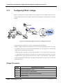
Configuring PPPoE + Bridge ...........................................................................................91
2.12.
Configuring PPTP ...........................................................................................................94
2.12.1.
Related Commands ................................................................................................... 94
2.13.
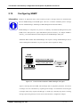
Configuring SNMP ..........................................................................................................96
2.14.
Gateway Management Commands ..............................................................................101
2.14.1.
EXEC Mode Commands ..........................................................................................101
2.14.2.
Global Configuration Mode Commands..............................................................105
2.15.
Fault Management and Debugging..............................................................................116
2.15.1.
Logging Commands .................................................................................................116
2.15.2.
Show Commands ......................................................................................................117
2.15.3.
Debug Commands ...................................................................................................121
2.16.
User, Password, Software Image and Configuration Files Management.................124
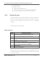
2.16.1.
User Registration and Change ................................................................................124
2.16.2.
Password Recovery...................................................................................................125
2.16.3.
Software Image Upgrade and Backup .................................................................129
2.16.4.
Backup and Restoring Configuration File..............................................................131
2.17.
Auto-Upgrade ...............................................................................................................133
Chapter 3 .
3.1.
Voice Configuration and the Related Commands.........................135
Overview........................................................................................................................135
3.1.1.
Voice over IP ..............................................................................................................135
3.1.2.
Codec and Mean Opinion Score...........................................................................136
3.1.3.
Dial Peer......................................................................................................................138
3.1.4.
Voice Port ...................................................................................................................140
3.2.
Configuring VoIP interface ...........................................................................................141
3.3.
Numbering Plan, Dialing Operation and Configuring Dial Peer ................................142
3.3.1.
Numbering Plan .........................................................................................................142
3.3.2.
Configuring Dial Peer................................................................................................142
3.3.2.1.
Inbound Dial Peer and Outbound Dial Peer.................................................142
3.3.2.2.
Configuring POTS Peer......................................................................................145
3.3.2.3.
Configuring VOIP Peer......................................................................................146
3.3.2.4.
Configuring Codec and VAD from Dial Peer ...............................................147
3.3.3.
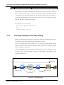
One-Stage Dialing and Two-Stage Dialing ...........................................................149
3.3.4.
Hunt Group.................................................................................................................150
3.3.4.1.
Basic Concept and Configuration .................................................................150
3.3.4.2.
Rerouting to PSTN...............................................................................................152
3.3.4.3.
Call bar................................................................................................................153
AddPac Technology Co., LTD
- 4 / 416-
VoiceFinder VoIP Gateway Configuration Guide (APOS 2.0) Release Version 3.1
3.3.5.
Number Forwarding and Prefix ...............................................................................154
3.3.6.
Configuring Number Expansion ..............................................................................155
3.3.6.1.
Preparing Number Expansion Table ...............................................................155
3.3.6.2.
Configuring Number Expansion ......................................................................156
3.3.7.
3.3.7.1.
Creating Translation Rule .................................................................................157
3.3.7.2.
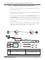
Applying Translation Rule to Inbound POTS Call...........................................158
3.3.7.3.
Applying Translation Rule to Inbound VOIP Call...........................................159
3.3.7.4.
Applying Translation Rule to Outbound Call.................................................159
3.3.7.5.
Applying Translation Rule to Connect Call ...................................................160
3.3.8.
3.4.
3.5.
3.6.
3.7.
Configuring Number Translation .............................................................................157
Configuring and Applying call-diversion ...............................................................162
3.3.8.1.
call-diversion ......................................................................................................162
3.3.8.2.
max-forward-hop ..............................................................................................163
3.3.9.
Configuring and Applying Call Transfer.................................................................164
3.3.10.
Configuring and Applying Call Pickup ..................................................................165
3.3.11.
Configuring and Applying Inbound-pots-peer.....................................................166
3.3.12.
Configuring and Applying PSTN Backup ...............................................................167
3.3.12.1.
busyout monitor .........................................................................................167
3.3.12.2.
busyout action ...........................................................................................167
Configuring Voice Port .................................................................................................169
3.4.1.
Configuring the Gateway Voice Port ....................................................................169
3.4.2.
Voice Port Configuration Items and Order ...........................................................169
3.4.2.1.
Configuring FXS and FXO Port .........................................................................169
3.4.2.2.
Configuring E&M Port........................................................................................170
3.4.2.3.
Tuning E&M Voice Port .....................................................................................172
3.4.2.4.
Configuring E1 Voice ........................................................................................173
3.4.2.5.
Activating/Deactivating Voice Port...............................................................174
Configuring E1 controller.............................................................................................175
3.5.1.
Connecting to PBX / PSTN........................................................................................175
3.5.2.
Common Configuration ...........................................................................................176
3.5.3.
Configuring ISDN PRI .................................................................................................177
3.5.4.
Configuring R2 ...........................................................................................................178
Configuring FAX Applications .....................................................................................179
3.6.1.
H.323 or SIP-Based T.38 FAX Relay...........................................................................179
3.6.2.
Configuring T.38 Fax Relay .......................................................................................180
3.6.3.
Configuring FAX Relay with Bypass.........................................................................180
Service Related Settings ..............................................................................................181
3.7.1.
ftp.................................................................................................................................181
3.7.2.
http ..............................................................................................................................181
AddPac Technology Co., LTD
- 5 / 416-
VoiceFinder VoIP Gateway Configuration Guide (APOS 2.0) Release Version 3.1
3.7.3.
ntp................................................................................................................................182
3.7.4.
snmp ............................................................................................................................182
3.7.5.
telnet ...........................................................................................................................183
3.8.
Other VoIP Related Settings .........................................................................................184
3.8.1.
Configuring H.323 Gateway ....................................................................................184
3.8.2.
Configuring H323 Call Start Mode ..........................................................................184
3.8.3.
Configuring SIP User Agent ......................................................................................185
3.8.4.
Configuring User Class ..............................................................................................186
Interoperable Features with IP-PBX ............................................................................188
3.9.
3.9.1.
Synchronizing Call-Forwarding Service of IP-PBX with PBX..................................188
3.9.2.
IP-PBX Polling among IP-PBX Cluster .......................................................................188
3.9.3.
Fault-Tolerant Call Attemption ................................................................................189
3.10.
VoIP Related commands .............................................................................................190
3.10.1.
VoIP Related Overall Commands...........................................................................190
3.10.2.
Global Configuration Commands..........................................................................196
3.10.2.1.
dial-peer call-hold .....................................................................................196
3.10.2.2.
dial-peer call-pickup.................................................................................197
3.10.2.3.
dial-peer call-transfer................................................................................198
3.10.2.4.
dial-peer hunt.............................................................................................199
3.10.2.5.
dial-peer ipaddr-prefix..............................................................................201
3.10.2.6.
dial-peer terminator ..................................................................................202
3.10.2.7.
dial-peer voice...........................................................................................204
3.10.2.8.
gateway......................................................................................................205
3.10.2.9.
num-exp ......................................................................................................206
3.10.2.10.
translation-rule............................................................................................209
3.10.2.11.
voice-port ...................................................................................................210
3.10.2.12.
voice class clear-down-tone ...................................................................211
3.10.2.13.
voice class codec .....................................................................................213
3.10.2.14.
voice class user ..........................................................................................215
3.10.2.15.
voice class clear-down-cadence ..........................................................217
3.10.2.16.
voice service ..............................................................................................221
3.10.2.17.
voip-interface.............................................................................................222
3.10.3.
Voice Port Configuration Commands ...................................................................223
3.10.3.1.
announcement..........................................................................................223
3.10.3.2.
busyout action ...........................................................................................224
3.10.3.3.
busyout backup.........................................................................................225
3.10.3.4.
caller-id........................................................................................................226
3.10.3.5.
comfort-noise .............................................................................................228
3.10.3.6.
connection plar .........................................................................................229
AddPac Technology Co., LTD
- 6 / 416-
VoiceFinder VoIP Gateway Configuration Guide (APOS 2.0) Release Version 3.1
3.10.3.7.
connection trunk .......................................................................................231
3.10.3.8.
description (voice port) ............................................................................233
3.10.3.9.
did ................................................................................................................234
3.10.3.10.
echo-cancel...............................................................................................236
3.10.3.11.
fax-early-detect .........................................................................................237
3.10.3.12.
high-dtmf-gain ...........................................................................................238
3.10.3.13.
input gain....................................................................................................239
3.10.3.14.
low-dtmf-gain.............................................................................................241
3.10.3.15.
output gain .................................................................................................242
3.10.3.16.
polarity-inverse ...........................................................................................244
3.10.3.17.
pstn-backup-port.......................................................................................245
3.10.3.18.
ring number ................................................................................................247
3.10.3.19.
shutdown (voice-port) ..............................................................................249
3.10.3.20.
timeout ........................................................................................................250
3.10.3.21.
translate-incoming ....................................................................................252
3.10.4.
Dial Peer pots / voice Configuration Commands................................................254
3.10.4.1.
answer-address ..........................................................................................254
3.10.4.2.
codec..........................................................................................................256
3.10.4.3.
description (dial-peer) ..............................................................................258
3.10.4.4.
destination-pattern....................................................................................259
3.10.4.5.
diversion ......................................................................................................261
3.10.4.6.
display-name..............................................................................................262
3.10.4.7.
dtmf-relay....................................................................................................264
3.10.4.8.
forward-digits..............................................................................................266
3.10.4.9.
huntstop ......................................................................................................268
3.10.4.10.
port...............................................................................................................269
3.10.4.11.
preference..................................................................................................270
3.10.4.12.
prefix ............................................................................................................272
3.10.4.13.
register .........................................................................................................273
3.10.4.14.
session target..............................................................................................275
3.10.4.15.
shutdown (Dial-Peer).................................................................................276
3.10.4.16.
sid .................................................................................................................277
3.10.4.17.
translate-outgoing.....................................................................................278
3.10.4.18.
vad...............................................................................................................280
3.10.4.19.
voice-class codec .....................................................................................281
3.10.4.20.
user-name...................................................................................................282
3.10.4.21.
user-password ............................................................................................284
3.10.4.22.
CLID(Calling Line Identification)..............................................................286
3.10.4.23.
call-wafting.................................................................................................288
AddPac Technology Co., LTD
- 7 / 416-
VoiceFinder VoIP Gateway Configuration Guide (APOS 2.0) Release Version 3.1
3.10.4.24.
3.10.5.
out-barred-group.......................................................................................290
sip-ua (SIP User Agent) Configuration Commands ..............................................292
3.10.5.1.
call-transfer-mode .....................................................................................292
3.10.5.2.
conference-server .....................................................................................294
3.10.5.3.
enable-ping................................................................................................295
3.10.5.4.
media-channel ..........................................................................................297
3.10.5.5.
min-se ..........................................................................................................299
3.10.5.6.
register .........................................................................................................301
3.10.5.7.
rel1xx ............................................................................................................303
3.10.5.8.
remove-all-binding ....................................................................................304
3.10.5.9.
retrycounter ................................................................................................305
3.10.5.10.
remote-party-id..........................................................................................306
3.10.5.11.
response ......................................................................................................308
3.10.5.12.
route-by-auxiliary .......................................................................................309
3.10.5.13.
set-local-domain........................................................................................310
3.10.5.14.
set-local-host ..............................................................................................312
3.10.5.15.
signaling-port..............................................................................................314
3.10.5.16.
force-forwarding........................................................................................315
3.10.5.17.
sip-server......................................................................................................317
3.10.5.18.
sip-username ..............................................................................................319
3.10.5.19.
sip-password ...............................................................................................320
3.10.5.20.
srv .................................................................................................................320
3.10.5.21.
timeout ........................................................................................................322
3.10.5.22.
user-register.................................................................................................324
3.10.5.23.
hook-flash-info-ignore ...............................................................................328
3.10.6.
Gateway, Voice Service, Voice Class and Rule Configuration Commands ..329
3.10.6.1.
announcement..........................................................................................329
3.10.6.2.
busyout monitor .........................................................................................330
3.10.6.3.
codec preference.....................................................................................331
3.10.6.4.
counter........................................................................................................332
3.10.6.5.
discovery.....................................................................................................333
3.10.6.6.
fax protocol ................................................................................................334
3.10.6.7.
fax rate ........................................................................................................336
3.10.6.8.
force-h245address-at-setup.....................................................................338
3.10.6.9.
force-starth245 ...........................................................................................339
3.10.6.10.
h323 call start..............................................................................................340
3.10.6.11.
inband-ringback-tone ..............................................................................341
3.10.6.12.
local-ringback-tone ..................................................................................342
3.10.6.13.
minimize-voip-ports....................................................................................344
AddPac Technology Co., LTD
- 8 / 416-
VoiceFinder VoIP Gateway Configuration Guide (APOS 2.0) Release Version 3.1
3.10.6.14.
max-frame ..................................................................................................346
3.10.6.15.
gkip ..............................................................................................................348
3.10.6.16.
h323-id .........................................................................................................350
3.10.6.17.
lightweight-irr ..............................................................................................351
3.10.6.18.
h323 call channel ......................................................................................352
3.10.6.19.
h323 call response .....................................................................................354
3.10.6.20.
max-digits....................................................................................................356
3.10.6.21.
password.....................................................................................................357
3.10.6.22.
public-ip ......................................................................................................358
3.10.6.23.
register .........................................................................................................359
3.10.6.24.
signaling-port..............................................................................................361
3.10.6.25.
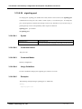
rule ...............................................................................................................362
3.10.6.26.
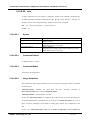
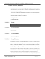
security password ......................................................................................364
3.10.6.27.
acf-dest-info ...............................................................................................365
3.10.6.28.
security permit-FXO ...................................................................................366
3.10.6.29.
security type (Secure VoIP gateway Specific) .....................................368
3.10.6.30.
security module (Secure VoIP gateway Specific)................................369
3.10.6.31.
timeout ........................................................................................................370
3.10.6.32.
translate-voip-incoming ...........................................................................372
3.10.6.33.
voice-confirmed-connect........................................................................373
3.10.6.34.
accept-fst-at-connect..............................................................................374
3.10.6.35.
Resource Threshold (RAI) ..........................................................................376
3.10.7.
Other Commands .....................................................................................................377
3.10.7.1.
clear h323 call ............................................................................................377
3.10.7.2.
clear voice-port .........................................................................................378
3.10.7.3.
show call active .........................................................................................379
3.10.7.4.
show call history .........................................................................................380
3.10.7.5.
show clear-down-tone .............................................................................381
3.10.7.6.
show codec-class......................................................................................382
3.10.7.7.
show dial-peer............................................................................................383
3.10.7.8.
show dialplan number ..............................................................................384
3.10.7.9.
show dialplan port.....................................................................................385
3.10.7.10.
show gateway ...........................................................................................386
3.10.7.11.
show num-exp............................................................................................387
3.10.7.12.
show translation-rule .................................................................................388
3.10.7.13.
show user-class...........................................................................................389
3.10.7.14.
show voice port .........................................................................................390
3.10.7.15.
show voip-interface...................................................................................391
3.10.7.16.
debug voip call..........................................................................................392
AddPac Technology Co., LTD
- 9 / 416-
VoiceFinder VoIP Gateway Configuration Guide (APOS 2.0) Release Version 3.1
3.10.7.17.
debug voip .................................................................................................393
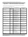
Appendix A
H.323 Call Termination Cause Codes.............................................395
Appendix B
References.........................................................................................400
Appendix C. Cable Specifications .........................................................................403
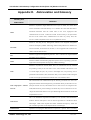
Appendix D.
Abbreviation and Glossary ..............................................................405
AddPac Technology Co., LTD
- 10 / 416-
VoiceFinder VoIP Gateway Configuration Guide (APOS 2.0) Release Version 3.1
[TABLES]
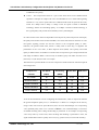
Table 2.1 Configuration Chart for each Uplink Interface for VoIP Gateway ................................. 86
Table 3.1 Compression Formats and MOS Scores ..................................................................137
Table 3.2 Delays in Code for each Compression Formats .........................................................138
Table C.1 Signal and Pinout of Console Port ..............................................................................403
Table C.2 Signal and Pinout Serial Ethernet Cable..................................................................404
AddPac Technology Co., LTD
- 11 / 416-
VoiceFinder VoIP Gateway Configuration Guide (APOS 2.0) Release Version 3.1
[FIGURES]
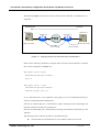
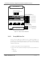
Figure 1.1 Network Configuration Example of VoiceFinder Gateways...................................... 18
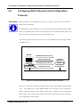
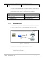
Figure 2.1 Communication between DHCP Server and Host A ................................................... 76
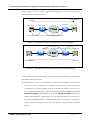
Figure 2.2 VoIP Network in IP Sharing Environment Diagram ..................................................... 85
Figure 2.3 VoIP Network Diagram for PPPoE + Bridge Environment .......................................... 91
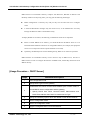
Figure 2.4 Communication between SNMP Manager and Agent .............................................. 96
Figure 3.1 Dial Peer Call Leg from a View Point of Source Gateway......................................139
Figure 3.2 Dial Peer Call Leg from a View Point of Destination Gateway...............................139
Figure 3.3 Outgoing Call from a View Point of POTS Dial Peer 1 ...........................................143
Figure 3.4 Outgoing Call from a View Point of POTS Dial Peer 2 ...........................................144
Figure 3.5 Two-Stage Dialing ....................................................................................................149
Figure 3.6 PSTN Rerouting .......................................................................................................152
Figure 3.7 An Example of VoIP Network .....................................................................................156
Figure 3.8 Call transfer Scenario ..............................................................................................164
Figure 3.9 Setup for Jumper of E&M Card ...............................................................................172
Figure 3.10 IP Network for T.38 FAX Relay ..............................................................................179
Figure 3.12 Detecting clear-down-tone parameter by using VoIP Gateway............................220
Figure 3.13 Basic SIP Network Diagram ..................................................................................300
Figure3.14 SIP Timer.................................................................................................................323
Figure C.1 10Base-T RJ-45 Connector ....................................................................................404
AddPac Technology Co., LTD
- 12 / 416-
VoiceFinder VoIP Gateway Configuration Guide (APOS 2.0) Release Version 3.1
Preface – About This Guide
The APOS 2.0 (APOS G2) voice configuration guide collects in one place
information that you need to implement APOS Release 3.1 voice features. It is
organized in the following chapters:
z Chapter 1. 『Overview』
This chapter describes its features and lists the hardware and software
specifications of the AddPac VoiceFinder gateways.
z Chapter 2. 『Configuring VoiceFinder Gateways for Operation』
This chapter describes how to use commands and all the related setting
modes by presenting configuration examples to configure AddPac VoIP
gateways as in a way to be suitable to the user’s environment and interface.
This chapter is very important and highly recommended to be studied
thoroughly.
z Chapter 3. 『Voice Port Configuration』
This chapter describes the type of connection being made and the type of
signaling to take place over this connection. In addition to the commands
for basic configuration, there are also fine-tuning for voice quality, enable
special features. This chapter is very important and highly recommended to
be studied thoroughly.
z Appendix A 『Reason Code Value for H. 323 Call Termination』
This appendix explains the reason code value for H.323 termination of
VoiceFinder Gateways and mapping Q.931 and H.225 call signaling and
communication between endpoints (call signaling) and the gatekeeper.
z Appendix B 『Reference Documents』
This appendix is organized with all the related RFC/OUT-T documents for
SIP/H.323/MGCP of VoIP protocol and TCP/IP protocol
z Appendix C 『Cable Specifications』
This appendix explains of console cable, V.35 cable and Ethernet cable
specifications to be used for the gateways
z Appendix D 『Acronyms and Glossary』
The acronyms and glossary of VoIP are organized in alphabetical order
AddPac Technology Co., LTD
- 13 / 416-
VoiceFinder VoIP Gateway Configuration Guide (APOS 2.0) Release Version 3.1
AddPac Technology Co., LTD
- 14 / 416-
VoiceFinder VoIP Gateway Configuration Guide (APOS 2.0) Release Version 3.1
The revision history of the VoiceFinder APOS Configuration Guide is listed as
to follow:
Release No.
Revision
Release 1.0
Initial Released
Release 1.1
Release 1.2
R&D
AddPac
and revised
R&D
Added commands
AddPac
and revised
R&D
and combined the
manuals
Release 3.0
AddPac
Added commands
Added commands
Release 2.0
Prepared by
AddPac
R&D
Added commands
AddPac
(8.10/8.23/8.30)
R&D
Release of
Release 3.1
APOS2.0 added
AddPac
commands and
R&D
revised
AddPac Technology Co., LTD
- 15 / 416-
VoiceFinder VoIP Gateway Configuration Guide (APOS 2.0) Release Version 3.1
[Document Conventions]
This publication uses the following conventions to convey instructions and
information:
Convention
Description
boldfast font
Commands and keywords
Italic font
Variable for which you supply values
[
Keywords or arguments that appear within square brackets are
optional
]
{x| y| z}
A choice of required keywords appears in braces separated by vertical
bars. You must select one.
<
This is the required variables to be replaced by numbers
>
[Safety Warnings]
Safety warnings appear throughout this publication in procedures that, if performed incorrectly,
might harm you. The following warning symbols precede each warning statement.
Danger
This warning symbol means danger.
You are in a situation that could cause bodily injury. Before you work on
any equipment, be aware of the hazards involved with electrical circuitry
and be familiar with standard practices for preventing accidents.
Warning
This symbol means that if you do not follow the procedure presented with
STOP
this symbol in this guide may result in a damage of the equipment or data
Caution
This symbol calls for the user’s attention to be careful. If the user doe not
loss.
follow the procedure presented with this symbol in this guide and misuses
the product, the damage in the software or data loss or loss of system
configuration can be resulted.
AddPac Technology Co., LTD
- 16 / 416-
VoiceFinder VoIP Gateway Configuration Guide (APOS 2.0) Release Version 3.1
Chapter 1 . Overview
1.1.
VoiceFinder Gateway Series
Information The AddPac VoiceFinder Gateway Series are the voice over IP gateways which allow using a
telephone at a low cost or even for free by supporting the voice communication using Internet
and leased-line in enterprise (head office and branch), public office and Small and Medium
Business (SMB) environment.
This gateway uses the latest voice compression and QoS algorithms of AddPac Technology’s
proprietary that allows maintaining the best voice quality regardless of whether the network is
broadband or narrow band. This gateway has the various voice interface modules including
FXS, FXO, E&M and digital E1/T1 that are suitable to the user’s demands and provides a great
flexibility to respond to the environmental changes of the user’s network and protects the
investment.
The AddPac VoiceFinder Gateways can be used in various network environments such as
leased line, ADSL and cable modems networking with fixed and dynamic IP environments. And
the gateway supports various network protocols such as static, RIP v1/2, OSPF v2 routing
function and Internet application functions such as NAT/ PAT. Especially in the dynamic
network environment, the VoIP and IP sharing platform provides the most economical and
efficient solutions in the broadband networks.
Also the VoiceFinder gateways are interoperable with the major vendor’s gatekeepers and
large-scale gateways. The VoiceFinder gateways are easy and simple to use, operate and
maintain. The gateway provides the voice integrated service solutions.
The gateways can support firewall in 2 ways, packet filtering and access list and limit the
access from the outside network by using sauce and destination address information.
Also the gateways can allocate IP addresses automatically to the network clients below the
router by using Dynamic Host Configuration Protocol (DHCP) and Network Address
Translation (NAT) allows the gateways to solve the shortage problem of IP address due to an
explosive increment of the users. At the same time, the internal IP address is hidden from the
outside for the enhancement of security features.
AddPac Technology Co., LTD
- 17 / 416-
VoiceFinder VoIP Gateway Configuration Guide (APOS 2.0) Release Version 3.1
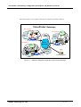
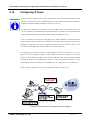
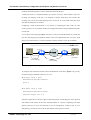
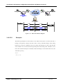
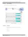
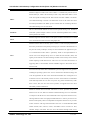
The following figure is an example of the network using the VoiceFinder Gateways.
VoiceFinder Gateways
Branch Office A
Branch Office B
PSTN
Fax
Edge
Network
LAN
10/100Mbps
Ethernet
LAN
10/100Mbps
Ethernet
WAN
PBX
Voicefinder Gateways
Head Office
Core
Network
PSTN
PBX
Fax
LAN
10/100Mbps
Ethernet
Frame-Relay
Network
A D SL
Cable
Fax
VoiceFinder Gateways
NMS
LA N
VoiceFinder Gateways
Network Management
Figure 1.1 Network Configuration Example of VoiceFinder Gateways
AddPac Technology Co., LTD
- 18 / 416-
VoiceFinder VoIP Gateway Configuration Guide (APOS 2.0) Release Version 3.1
1.2.
Main Features
Information The main features and technical specification are described in the followings:
Network / Voice Interface
The AddPac Voice Finder Gateway Series have been designed with the system architecture
which can provide enriched system memory and diversified voice interfaces.
z
High performance VoIP service solution integrated with data/voice
z
Hardware design of Extensible Modular Structure
(Except stand alone types such as AP160,AP200,AP1100,AP1200 )
z
High Performance 32bit RISC Microprocessor
z
2 or 4-Voice Network Module independently (depending on product models)
(Refer to the hardware specifications of the relevant product model)
z
Fixed 1-Port 10 or 100Mbps Fast Ethernet Interface for LAN Service (RJ45)
(Refer to the hardware specifications of the relevant product model)
z
Fixed 1-Port 10 or 100Mbps Ethernet Interface for WAN Side Connection (RJ45)
(Refer to the hardware specifications of the relevant product model)
z
Fixed 1-Port Asynchronous Serial Interface for Console Port (RJ45)
(Refer to the hardware specifications of the relevant product model)
z
Optional 4-Ports FXS Voice Processing Network Module (4 x RJ11)
(Refer to the hardware specifications of the relevant product model)
z
Optional 4-Ports FXO Voice Processing Network Module (4 x RJ11)
(Refer to the hardware specifications of the relevant product model)
z
Optional 4-Ports E&M Voice Processing Network Module (4 x RJ11)
(Refer to the hardware specifications of the relevant product model)
z
Optional 2-Ports FXO and 2-Ports FXS Voice Processing Network Module (4 x
RJ11)
(Refer to the hardware specifications of the relevant product model)
z
Optional 1-Ports Digital E1 ISDN-PRI/R2/DTMF Processing Network Module (1 x
RJ48)
(Refer to the hardware specifications of the relevant product model)
z
Optional 1-Ports Digital T1 ISDN-PRI/R2/DTMF Processing Network Module (1 x
RJ48)
(Refer to the hardware specifications of the relevant product model)
z
1U x 19” Rack Mountable Standard Chassis
(Refer to the hardware specifications of the relevant product model)
AddPac Technology Co., LTD
- 19 / 416-
VoiceFinder VoIP Gateway Configuration Guide (APOS 2.0) Release Version 3.1
z
AC Power Supply Unit (Free Voltage)
z
Various System LED indicator
IP Routing Protocols
The following are the specifications for IP routing protocol supported by the Voice Finder VoIP
Gateway:
z
Static, RIP v1/v2, OSPF v2 Routing Protocol
z
Transparent Bridging (IEEE Spanning Tree Protocol)
z
IEEE802.1Q VLAN Routing
Voice over IP Service
The specification of Voice over IP features are listed as to follow:
z
ITU-T H.323 v3 VoIP Protocol
z
ITU-T H.235 Security Feature
z
ITU-T H.323 Gateway, Gatekeeper
z
Session Initiation Protocol (SIP)
z
MGCP Protocol
z
H.323, SIP, MGCP Concurrent Triple Stack
z
G.723.1, G.729.A, G.711 Voice Compression
z
Various Voice Processing Feature
z
9
VAD(Voice Activity Detection)
9
T.38 G3 FAX Relay(In-band and Out-band)
9
DTMF(Dual Tone Multi Frequency)
9
CNG (Comfort Noise Generation)
9
G.168 Echo Cancellation
Enhanced QoS Management Features for Voice Traffic
WAN Service
The VoiceFinder VoIP Gateway Series supports the following WAN features:
z
Point-to-Point Protocol over Ethernet (PPPoE)
z
ADSL (Static IP and dynamic IP) and Cable Modem (DHCP)
Network Managements
AddPac Technology Co., LTD
- 20 / 416-
VoiceFinder VoIP Gateway Configuration Guide (APOS 2.0) Release Version 3.1
The Gateway Series provide various network management features for systematic equipment
management as to follow:
z
Interoperation with AP-VPMS for systematic equipment management
z
Standard SNMP Agent and standard MIB II, Bridge MIB
z
Console feature through asynchronous port
z
Telnet and login enabling remote control
z
QoS through traffic queuing
z
Web-based network management
Security Functions
The gateways also support diverse security features as to follows:
z
Standard & Extended IP Access List for network security
z
Enable/Disable a specific network protocol
z
Account management features for multi-level users
z
Auto-disconnect for Telnet/Console Sessions
z
PPP User Authentication (PAP and CHAP)
Operation and Managements
The gateways support the following operation and Management:
z
System Performance Analysis for Process, CPU, Connection I/F
z
Configuration Backup & Restore for APOS Managements
z
Debugging, System Auditing, and Diagnostics Support
z
Diagnostic system enabling network packet analysis
z
Debussing call process
z
System Booting and Auto-rebooting with Watchdog Feature
z
IP Traffic Statistics with Accounting
z
IP Traffic Statistics with Accounting
Other Scalability Features
AddPac Technology Co., LTD
- 21 / 416-
VoiceFinder VoIP Gateway Configuration Guide (APOS 2.0) Release Version 3.1
The gateway support the other scalability features as to follow:
z
DHCP Server & Relay Functions
z
Network Address Translation (NAT) Function
z
Remote Upgrade for APOS Management using FTP/TFTP
z
Cisco Style Command Line Interface(CLI)
z
Network Time Protocol (NTP)
Interoperability Features
The AddPac VoiceFinder Gateway Series ensures reliable network interoperability of mutual
operation with other major vendors’ switches and voice gateway equipment
z
CISCO AS5300 Series, CISCO 2600/3600 Series (H.323, SIP)
z
Cisco Call Manager (MGCP)
z
Xener System Softswitch (H.323, MGCP, SIP)
z
3Com Total Control Series(H.323, SIP)
z
Clarent Gateway 3.0 Series (H.323)
z
Soners Softswitch (H.323, SIP)
z
NEC Softswitch (SIP)
z
NTT Softswitch (SIP)
z
major vendors’ VoIP gateways, gatekeepers including Lucent
AddPac Technology Co., LTD
- 22 / 416-
VoiceFinder VoIP Gateway Configuration Guide (APOS 2.0) Release Version 3.1
1.3.
APOS Internetworking Software
Information This section provides and an overview of AddPac Operating System (APOS) Internetworking
Software as to follow:
APOS Internetworking Software for AP Router, Gateway
APOS Internetworking Software has been designed with the latest Embedded Real-time Operation System and
implemented with the architecture based on continuous scalability of advanced networking software,
outstanding reliability and stability and Quality of Service (QoS).
In addition APOS internetworking
software has been developed with the system architecture of Building Block concept which provides
easy-to-upgrade for integrating various types of network interface or additional network protocols.
Industrial Standard Network Protocol Stack
APOS Internetworking Software supports the industrial standard network protocol stack. This
protocol stack includes those protocols which can support the data networking for WAN/LAN
and ATM and network management or security, VPN and other various protocols are included.
Integrated Networking Solution
APOS Interworking Software does not just support only data networking but also Voice over
Internet Protocol: it provides the solution which can inter-work, with the different network
infra-structure such as VoIP which is integrated with voice and data, ATM, Frame-Relay, ISDN
and PSTN.
Optimized Performance and Functionality
APOS Internetworking Software provides the outstanding data processing capability and idea;
bandwidth control ability for the complex traffic. This implementation of maximized functions
can be used with the outstanding solution to design an ideal network together with many
mandatory functions supported by APOS.
AddPac Technology Co., LTD
- 23 / 416-
VoiceFinder VoIP Gateway Configuration Guide (APOS 2.0) Release Version 3.1
Easy to use, Easy to Install and Maintain
APOS Internetworking Software guarantees simple and compatible interoperability by using
the industrial standard command for the user’s convenience. In addition, maintenance and
operations are easy with Web-based Management and remote management.
AddPac Technology Co., LTD
- 24 / 416-
VoiceFinder VoIP Gateway Configuration Guide (APOS 2.0) Release Version 3.1
Chapter 2 . The Gateway Configuration and Its
Commands
This chapter describes how to configure VoiceFinder Gateways and explains the commands.
2.1.
Booting the Gateway
This chapter describes how to configure VoiceFinder Gateways and explains the commands.
All the commands for configuring the gateways can be used by accessing Telnet or connecting
to console.
After the power is turned on, the gateways go through the following process:
z
The gateways go through self-testing process then check their basic operation of CPU,
memory and interface.
z
After the Boot Loader is performed, the gateways look for the software image file. At the
default configuration, the gateway is to load the software in the flash memory
z
If the gateways can not find the software image file from the flash memory, the stand-by at
the boot mode until they can download the proper software (at this time, FTP or TFTP
protocol can be used to download the proper software for the gateways).
z
The gateways operate basing on the setting information which is saved after the software is
downloaded.
Caution
When the system is booted for the first time, the gateways perform the settings and these
settings must be saves by the commands of ‘write’ or ‘copy running-config’.
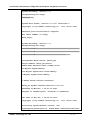
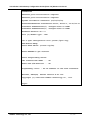
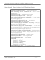
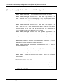
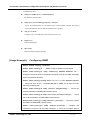
After the booting is processed normally, you can see the following message:
AddPac Technology Co., LTD
- 25 / 416-
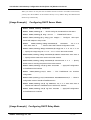
VoiceFinder VoIP Gateway Configuration Guide (APOS 2.0) Release Version 3.1
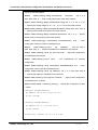
System Bootstrap, Version 1.2
Decompressing the image:
########[OK]
System Boot Loader, Version 2.4.0/2. Board Rev 0
Copyright (c) by AddPac Technology Co., Ltd. Since 1999.
Ethernet port initialization complete
The "BOOT LOADER" is ready
BOOT_login:
System Bootstrap, Version 1.2
Decompressing the image:
##########################################################
##########################################################
#############################################[OK]
VoiceFinder AP100 Series (AP100_G2)
Serial Number: AP100_G2-fffe7e
32BIT RISC Processor With 112MHz Clock
16 Mbytes System Memory.
512 Kbytes System Boot Flash Memory
2 Mbytes System Flash Memory
1 RS232 Serial Console Interface
AP100_G2 System software Revision 8.41.100
Released at Wed Nov 7 21:27:13 2007
Program is 1724824 bytes, checksum is 0xdd1b378
UTC Time is Thu Jan 1 00:00:00 1970
Copyright (c) by AddPac Technology Co., Ltd. Since 1999.
Allocating system mbuffer counter: 256
Loading file system(ver2.2), flash-base: 0xb01f0000 ram-base:
AddPac Technology Co., LTD
- 26 / 416-
VoiceFinder VoIP Gateway Configuration Guide (APOS 2.0) Release Version 3.1
0x948e5098
Ethernet port initialization complete
Ethernet port initialization complete
System utilization reference (14/14/14/15)
Attach FastEthernet Interface at Slot 0, Port 0-1, <0-0>/<0-1>
Interface FastEthernet0/0, changed state to DOWN
Interface FastEthernet0/1, changed state to DOWN
Hardware Revision ID = 0
Slot (0) Module type : FXS
can't open configuration file [flash:/apos.cfg]
RTA Module Ready
Start HTTP Server (listen tcp/80)
Press RETURN to get started.
Start Target Debug Server
CPU internal DSP SRAM .... OK
Audio DSP S/W download ... OK
VoipGateway::Init1 - No IP address on the VoIP Interface
Welcome, APOS(tm) Kernel Version 8.41.100.
Copyright (c) 1999-2006 AddPac Technology Co., Ltd.
Login:
AddPac Technology Co., LTD
- 27 / 416-
VoiceFinder VoIP Gateway Configuration Guide (APOS 2.0) Release Version 3.1
2.2.
Command Instructions
This chapter describes how to configure VoiceFinder Gateways and explains the commands.
All the commands for configuring the gateways can be used by accessing Telnet or connecting
to console.
After the power is turned on, the gateways go through the following process:
z
The gateways go through self-testing process then check their basic operation of CPU,
memory and interface.
z
After the Boot Loader is performed, the gateways look for the software image file. At the
default configuration, the gateway is to load the software in the flash memory
z
If the gateways can not find the software image file from the flash memory, the stand-by at
the boot mode until they can download the proper software (at this time, FTP or TFTP
protocol can be used to download the proper software for the gateways).
z
The gateways operate basing on the setting information which is saved after the software is
downloaded.
The gateway command marked with the asterisk mark ‘*’ is not currently supported, but it will
be supported in the near future.
The commands that are related to IPv6 can be applied for the product which supports IPV6.
Some products can be applied with IPv6 in APOS 2.0 version.
If there is no corresponding command, the product does not support the function.
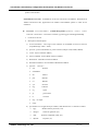
Example) (name of the product model)# clear ?
z
arp-cache
Clear the entire ARP cache
z
cdp
CDP information
z
counters
Clear counters on one or all interfaces
AddPac Technology Co., LTD
- 28 / 416-
VoiceFinder VoIP Gateway Configuration Guide (APOS 2.0) Release Version 3.1
Caution
z
h323
[VoIP] Clear H323 call
z
ip
IP information
z
ipv6
IPv6 information
z
system
APOS specific information
z
utilization
Clear system usage information
z
voice-port
[VoIP] Clear call on voice port
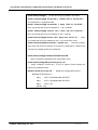
‘No’ command can be used to cancel the command which has been set already. In case of
canceling the command with the default value by using ‘no’ command, the optional values of
the command are to be set back to the default value.
Example) (name of the product model)(config)# no ?
z
access-list
Add on access list entry
z
access-list-all
Add on access list entry
z
arp
Modify ARP table parameters and entry
z
banner
Set banner string
z
call-diversion
[VoIP] Remove call diversion profile
z
cdp
CDP information
z
clock
Configure time-of-day clock
z
spe-id
reset cpe-id
z
debug
debugging control
z
dhcp
Enable DHCP server or relay
z
dial-peer
[VoIP] Remove Dial Peer
z
dialpattern-group
[VoIP] Remove Dial Pattern Group
z
dns
host aliases
z
ems-server
[VoIP] Config EMS server
z
enable
Modify enable password parameters
z
ftp
file Transfer Protocol
z
hostname
Reset system’s network names
z
http
Enable HTTP
z
interface
Select an interface to configure
z
ip
IP information
z
ipv6
IPv6 information
z
key
Authentication key management
AddPac Technology Co., LTD
- 29 / 416-
VoiceFinder VoIP Gateway Configuration Guide (APOS 2.0) Release Version 3.1
z
logging
Modify message logging facilities
z
mount
Mount File system device
z
num-exp
[VoIP] Remove Number Expansion
z
radius-server
[VoIP] Config RADIUS server
z
route-map
Create route-map or enter route-map command
mode
z
script
APOS script string
z
serial
Set system’s configuration serial string
z
service
Set up miscellaneous service
z
snmp
Config a SNMP parameters
z
system
Set system parameter
z
telnet
Telnet port
z
translation-rule
[VoIP] Remove translation rule
z
username
Establish User Name Authentication
z
utilization
utilization
z
voice
[VoIP] Reset Voice class or service configuration
z
voip-interface
[VoIP] Set VoIP interface and address
AddPac Technology Co., LTD
- 30 / 416-
VoiceFinder VoIP Gateway Configuration Guide (APOS 2.0) Release Version 3.1
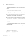
2.2.1.
User Mode Commands
All the commands for configuring VoiceFinder Gateway can be used by accessing to Console
or Telnet terminal (VT-100 terminal). And these commands can be used by Web-based (HTTP)
management.
In the commands, there is the user mode for accessing data network, administrator’s mode for
looking up the configuration status or debugging and the configuration mode for changing the
environment settings or create the new ones.
The followings are the attributes of commands for configuring VoiceFinder Gateways:
z
You do not have to enter all the command letters and just entering a part of the command
can be recognized automatically. For instance, if you want to enter ‘show’ command, just
entering ‘sh’ or ‘sho’ can be automatically recognized as ‘show’.
z
On-line help
provides the list of commands with usage sentences when a wrong
command is entered.
z
For the messages that can take more than one screen to be displayed, ‘more’ command is
used to display the rest of messages in each additional screen.
z
z
‘Help’ and ‘?’ command can used to see description of the command.
There are 3 different types of modes for the gateway commands. The commands for each
mode can be described in the following:
AddPac Technology Co., LTD
- 31 / 416-
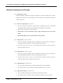
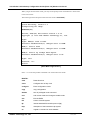
VoiceFinder VoIP Gateway Configuration Guide (APOS 2.0) Release Version 3.1
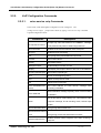
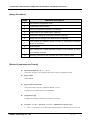
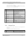
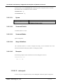
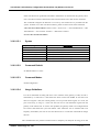
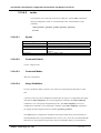
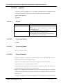
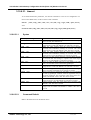
2.2.2.
Administrator Mode Commands
The administrator mode command is used for the administrator only who logs into the gateway.
To use this command, you must log in to the gateway by the root account. An entrance to the
configuration of the gateway is possible only when you log in as administrator mode.
At the administrator, all the commands in the user mode can be used.
The prompt for the administrator mode can be displayed as ‘(product model)#’.
Command
auto-upgrade
clear
clock
configure
copy
debug
disable
disconnect
dnsquery
dnsrv
end
erase
exit
fsh
help
no
nsupdate
ntpdate
ping
ping6
quit
reboot
show
telnet
terminal
tftp
traceroute
traceroute6
who
whoami
write
AddPac Technology Co., LTD
Description
Sets to upgrade the image by using HTTP
Initializes the initial counter and statistics
Sets the present year, date and time
Enters to the configuration mode
Copies running config to startup config
Debugs the overall system
Enters to the user mode
Closes VTY connection
Used for DNS Query test
Used for DNS SRV Record Test
Enters to the administrator mode
Deletes config file
Moves to a notch previous mode from the present
Enter File Shell
Displays APOS help screen
Deletes the present configuration
Transmits updated information to Name Server
Receives the clock information from ntp server
Checks the network connection (IPv4)
Checks the network connection (IPv6)
Equals to exit
Reboots the system
Checks the present status of the configuration
Connects remotely
Sets to display the terminal and debussing information
Transmits the file by tftp
Checks the route (IPv4)
Checks the route (IPv6)
Displays a user’s information who is currently connected
Displays a user’s information for a terminal who is currently
connected
Saves the present configuration
- 32 / 416-
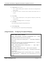
VoiceFinder VoIP Gateway Configuration Guide (APOS 2.0) Release Version 3.1
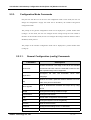
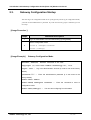
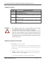
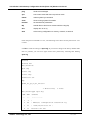
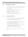
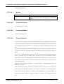
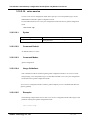
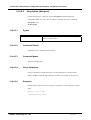
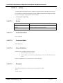
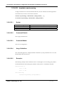
2.2.3.
Configuration Mode Commands
Only the user with the root can access to the configuration mode. In this mode, the user can
change the configuration. Largely the mode can be divided by the interface and general
configuration mode.
The prompt of the general configuration mode can be displayed as ‘product model name
(config)#’. In this mode, the user can configure all the settings except the ones related to
interface. In the interface mode, the user can configure the settings related to interface such as
IP address, WAN protocol.
The prompt of the interface configuration mode can be displayed as ‘product model name
(config-if)’.
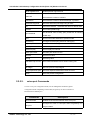
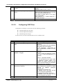
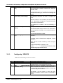
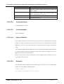
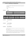
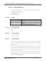
2.2.3.1.
General Configuration (config) Commands
Command
Description
Creates access-list. The range of #1~99 is the standard
access-list
access-list and #100~199 is the extended access list. Also
the expanded range can be supported.
Configures
the
VoIP
call
termination
cause
value
application
mappings.
Deletes and adds a particular Ethernet address from ARP
arp
table. Also performs ARP table.
Sets to download the firmware and script file by using
auto-upgrade
HTTP.
bridge
Configures the settings related to bridge.
call-diversion
Configures call-division.
cdp
Global CDP configuration subcommands
clock
Configures System Time of the gateway
console
Sets the serial console
controller
Configures the settings for E1/ T1 interfaces
dhcp
Configures settings for DHCP server and relay
AddPac Technology Co., LTD
- 33 / 416-
VoiceFinder VoIP Gateway Configuration Guide (APOS 2.0) Release Version 3.1
dialpattern-group
Configures dial pattern group
dial-peer
Configures dial-peer as for VoIP command
dns
Configures the setting for DNS server
ems-server
Configures connection to AP-VPMS
exit
Returns to the previous mode
Used for operating with H.323 Gatekeeper. It only works
gatekeeper
with the product that supports the gatekeeper.
Configure the settings for the voice gateway as for VoIP
gateway
command
hostname
Changes a name of the gateway from the network
http
Configures the settings for HTTP server
Enters to the interface configuration mode or creates a
Interface
logical interface
ip
Enables IP routing
ipv6
Configures the settings for IPv6 and others
ip-tos
Sets a value of IP Type of Server Field
key
Sets the authentication key for the routing protocol
logging
Changes or configures message logging
mgcp
Sets MGCP connection
Cancels the command which has been entered or return
no
to the default value
num-exp
Configures VoIP settings of Phone Number Extension
radius-server
Configures the settings for connection with RADIUS server
recovery
Configures the settings for password recovery
remote-log
Configures the settings for syslog server
script
Configures the settings for auto-upgrade/ntp server
When the settings of auto-config are used, it determines a
serial
serial number for the setting information.
sip-ua
Enters to the setting mode related to SIP User Agent
snmp
Configures the settings for SNMP
Configures the settings for SSCP Protocol related. The
sscp
usage of this command is limited to the product that can
support SSCP only.
translation-rule
AddPac Technology Co., LTD
Configures the setting for translation rule
- 34 / 416-
VoiceFinder VoIP Gateway Configuration Guide (APOS 2.0) Release Version 3.1
username
Changes or registers a gateway user
This is an operation to set a time interval for checking the
utilization
usage ratio of CPU, Ethernet, serial and others
voice
Configures the settings for VoIP service or codec
voice-port
Configures the setting for VoIP port
voip-interface
Configures the setting for VoIP interface
write
Save the present configuration
AddPac Technology Co., LTD
- 35 / 416-
VoiceFinder VoIP Gateway Configuration Guide (APOS 2.0) Release Version 3.1
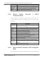
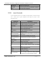
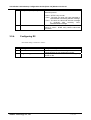
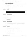
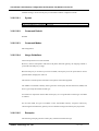
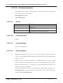
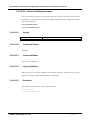
2.2.4.
Network interface Configuration Commands
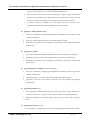
2.2.4.1.
Ethernet interface Commands 1
Interface configuration mode assigns a particular interface for the settings of the configurations
mode. The gateway has 1 Ethernet interface for the uplink and another Ethernet interface for
the down link.
Commands
Description
bandwidth
Set the bandwidth informational parameter to kilobits
bridge-group
Specify the bridge parameter.
cdp
Enable CDP of the interface
description
Describe the text in interface configuration mode
Configure
encapsulation
the
(supporting
encapsulation
Ethernet,
IEEE
for
a
802.1q
designated
VLAN,
interface
IEEE802.3
Encapsulation)
exit
Return to the previous mode
end
Return to the beginning mode
full-duplex
Set Ethernet to full- duplex
half-duplex
Set Ethernet to half-duplex
Interface
Configure another interface
Ip
To configure settings of IP service related and IP protocol.
ipv6
To set the settings of IPv6 service related and IP protocol
Cancel the command which has been entered or returns to the
no
default value.
mac-address
Change a value of mac-address of a designated interface
multicast
Configure a designated interface to multicast flag
Configure a designated interface to receive all the multicast
multicast-all
packets as a user’s command
Specify a value for accessing Point-to-Point Protocol in interface
ppp
configuration mode
peer
Allocate the addresses while PPP is in operation
pppoe
Specify a value for accessing PPP over Ethernet
AddPac Technology Co., LTD
- 36 / 416-
VoiceFinder VoIP Gateway Configuration Guide (APOS 2.0) Release Version 3.1
qos-control
Specify a value of QoS traffic control of a designated interface.
shutdown
Perform the administrative down to a designated interface
speed
Specify a physical speed of a designated link
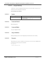
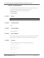
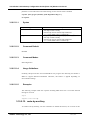
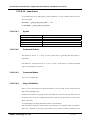
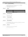
2.2.4.2.
Ethernet
interface
Configuration Mode)
Commands
2
(IP/IPv6
IP related commands can be configured from the assigned interface. The prompt can be shown
as product model name (config-if)#. The commands listed below can be shown by using
(config-if)# ip ?.
Command
Description
Apply the access-list, which has been configured from global
access-group
configuration mode, to an interface
accounting
Apply IP Account List to a designated interface
address
Change or configure IP/IPv6 address for a designated interface
dhcp
Specify DHCP configuration for interface
exit
Return to the previous configuration mode
nat
Enter NAT interface configuration mode
nd
Specify a default value for Pv6 ND (Neighbor Discovery)
mtu
Configure IP MTU of a designated interface
policy
Configure an ip route-map
policy-group
Set the policy which has been applied to a designated interface
Specify an option whether to apply route-cache to a designated
route-cache
interface
tcp
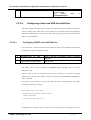
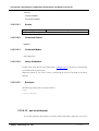
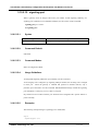
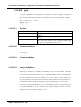
2.2.4.3.
Specify a MSS value of TCP header
Ethernet interface Commands 3 (PPP Configuration
Mode)
This is the command to be configured for the designated interface with ppp encapsulation from
AddPac Technology Co., LTD
- 37 / 416-
VoiceFinder VoIP Gateway Configuration Guide (APOS 2.0) Release Version 3.1
interface Fasrtethernet configuration mode.
Command
Description
accm
Configure the text map to be used for Async port
authentication
Configure the authentication method of ppp link
ccp
Enable PPP CCP
chap
Set a value of CHAP authentication
lcp
Enable PPP Link control negotiation
ipcp
Request for ipcp option parameters
Ipv6cp
Request for option parameters of IPv6CP
pap
Configure PAP authentication parameters+
AddPac Technology Co., LTD
- 38 / 416-
VoiceFinder VoIP Gateway Configuration Guide (APOS 2.0) Release Version 3.1
2.2.5.
VoIP Configuration Commands
2.2.5.1.
voice service voip Commands
In this mode, VoIP related global configuration can be configured.
The
(config-vservice-voip)# prompt will be shown by typing “voice service voip” command
at global configuration mode.
Commands
Description
Accept only fast start element at CONNECT message.
accept-fse-at-connect
This prevents early listen of inband ring back tone
announcement
Enables a voice announcement of the voice-port
busyout
Enable busyout monitoring
cdr
Set syslog CDR (Call Deatail Record) format
counter
Set counter values
default
Set default values
delayed-connect
Enable delayed connect on FXO
display
Set display name option either H.323 id or E.164 address
dynamic-payload-type
Set dynamic payload type
end
Return to the beginning (exec)
exit
Return to the previous mode
fax
Set fax protocol and rate
force-h245address-at-
Set H.245 address at H.323 SETUP message when
setup
tunneling is disabled
Send startH245 message explicitly when H.323 tunneling
force-starth245
is disabled
Set H.323 specific mode settings (i.e., fast start/slow start,
h323
response message, H.245 tunneling mode, channel open
mode)
ignore-dtmf-abcd-tone
Set ignoring ABCD DTMF tone
ignore-reverse-channel
-info
Set ignoring reverse fast start element on ACK
Enable transmit inband ringback tone when receiving a
inband-ringback-tone
voip call
AddPac Technology Co., LTD
- 39 / 416-
VoiceFinder VoIP Gateway Configuration Guide (APOS 2.0) Release Version 3.1
local-ringback-tone
Enable pseudo ring back tone
max-call
Set maximum number of call limit
max-frame
Set maximum number of audio frames per Tx packet
minimize-voip-ports
Minimize UDP/TCP port range using for VoIP
no
Cancel the entered command and return to default value
modem
Set modem passthrough
Set threshold value of delay, jitter, packet loss for sending
qos-threshold
SNMP trap
quit
Exit current mode and down to previous mode
remote-log
Configure remote syslog server for call logging
rtp-nat-pat
Set RTP NAT/PAT configuration
security
Set security parameters
hold-tone-play
Set tone play for hold call
static-jitter-buffer
Set static jitter buffer for RTP
timeout
Set timeout value
timing
Set timing value
translate-voip-incomin
Set number translation rule for VoIP incoming call
g
2.2.5.2.
ttl-margin
Set TTL (Time To Live) margine
voip-response-on-pstn
Set VoIP response mode when call is on PSTN
write
Save the present configuration
voice-port Commands
To enter voice-port configuration mode, use the voice-port command in global
configuration mode. Depending on the model, the gateway can have a number of
FXS/FXO/E1/T1/E&M ports.
Commands
announcement
Description
Enables a voice announcement of the voice-port
Configure an action of voice-port when the gateway is in
busyout
busyout status.
AddPac Technology Co., LTD
- 40 / 416-
VoiceFinder VoIP Gateway Configuration Guide (APOS 2.0) Release Version 3.1
caller-id
Enable caller-id
clear-down-tone-detect
Detect clear down tone
comfort-noise
Enable comfort-noise to be generated
compand-type
Set compand type (A-law or U-law)
connection
Set connection plar
description
Enter a description of the voice-port
dial-tone-generate
Enable dial tone generation
Apply DID(Direct Inward Dialing) to a corresponding
did
voice-port
echo-cancel
Enable echo cancelation
end
Return to the beginning (exec)
exit
Return to the previous mode
fax-early-detect
Apply fax-early-detect to a corresponding voice-port
Enable forced clear down on low level signal (FXO or
force-clear-down
E&M)
help
Display APOS help
high-dtmf-gain
Set a high frequency dtmf gain value to DTMF tone
input
Adjust input gain (volume) value
low-dtmf-gain
Set a low frequency dtmf gain value to DTMF tone
no
Cancel the entered command and return to default value
non-confirmed-connect
Configure non-confirmed-connect from E&M module
output
Adjust output gain (volume) value
Configure polarity-inverse settings (FXS : generate, FXO :
polarity-inverse
detect)
pstn-backup-port
Configure peer PSTN(FXO) backup port settings
quit
Return to the previous mode
ring
ring cadence and frequency
shutdown
Shut down the port
signal
Set signal type
timeout
Set timeout value
timing
Set timing value
translate-incoming
Set called/calling number translation-rule to the port
type
Set E&M type
write
Save the present configuration
AddPac Technology Co., LTD
- 41 / 416-
VoiceFinder VoIP Gateway Configuration Guide (APOS 2.0) Release Version 3.1
2.2.5.2.1.
E1/T1 Controller Commands
E1/T1 controller configuration mode assigns a specific controller port from global
configuration mode, and then it does the settings. Depending on a model, the gateway can have
a number of E1/T1 ports.
Commands
Description
chan-number-order
Set an order for opening a channels for the incoming call
channel-group
Organize a group of channels for use
clock-source
Set to ISDN clock-source
end
Return to the beginning mode (Exec)
exit
Return to the previous mode
help
Display APOS help
isdn
Set ISDN related options
Cancels the command has been enters and return to a
no
default value
out-barred-group
Set the channel group for blocking an outgoing call
quit
Return to the previous mode
r2
Set R2 related options
signaling-type
Select a signaling type from ISDN/DTMF/R2
write
Save the present configuration
2.2.5.3.
Pots peer Commands
The prompt changes to model name (config-dialpeer-pots-0)# after dial-peer voice [0~65535]
pots is entered from global configuration mode.
Commands
Description
application
Set pots to MGCP
call-waiting
Enables call-waiting
destination-pattern
Set a destination pattern
diversion
Set a call diversion
AddPac Technology Co., LTD
- 42 / 416-
VoiceFinder VoIP Gateway Configuration Guide (APOS 2.0) Release Version 3.1
forward-digits
Forward an incoming number arrived on the pots
huntstop
Set hunting stop on this peer when call routing
inbound-pots-peer
Set inbound pots peer when this peer call out
Cancels the pots peer command has been entered and
no
return to the default value
numbering-type
Change a numbering type of pots peer
out-barred-group
Set outbound call barred group for the pots
outbound-notify
Set a beep sound for the outbound call
port
Set a voice port binding to this pots
preference
Set a precedence order for dial-peer hunt selection
prefix
Set the prefix in pots peer configuration mode
quit
Return to the previous mode
recording
Configure a recording related information
register
Register pots peer to server (H.323/SIP)
shutdown
Shut down pots peer
user-name
Enter an authentication ID when to register
Enter a password for the authentication ID when to
user-password
register
url
Set url type to tel type
display-name
Display a name of the pots for SIP connection
to-display-name
to-display-name of pots for SIP connection
translate-outgoing
Configure a number translate rule for the outbound call
write
Save the present configuration
2.2.5.4.
Voip peer Commands
Entering dial-peer voice [0~65535] voip from global configuration mode changes the prompt to
model name (config-dialpeer-voip-1000)#.
Commands
Description
Use a calling party number of the inbound call to find the
answer-address
voip peer call for an arriving VoIP inbound call on network
calling-pattern
Set calling pattern to outbound call
clid
Change CLID( Calling Line Identification) mode
codec
Specify a static codec type
AddPac Technology Co., LTD
- 43 / 416-
VoiceFinder VoIP Gateway Configuration Guide (APOS 2.0) Release Version 3.1
codec-variant
Set a variant value of G.723.1/G.729 codec
description
Enter a description of voip peer configuration mode
Specify a destination-patter in voip peer configuration
destination-pattern
mode
dtmf-relay
Specify the dtmf-relay usage
end
Return to the beginning mode (Exec)
exit
Return to the previous mode
huntstop
Set hunting stop on this peer when call routing
Specify a rate and fax protocol in voip peer configuration
fax
mode
max-forward-hop
Set the maximum call forward hop count
Cancel the entered command and return to the default
no
value
modem
Specify a modem passthrough
numbering-type
Specify a numbering type
out-barred-group
Specify an outbound call barred group
out-permit-group
Specify an outbound call permit group
preference
Specify a preference
quit
Return to the previous mode
recording
Specify a recoding related information
redundant-rtp
Enable redundant rtp for lossy network
session
Specify a session target address and protocol of this peer
shutdown
Shut down voip peer configuration mode
Enable SID (Silence Insertion Descriptor) packet sending
sid
mode when VAD (Voice Activity Detection) is enabled
translate-outgoing
Specify the number translation rule for an outbound call
url
Configure url type to tel type
Configure the user-privacy function when SIP server is
user-privacy
connected
vad
Enable VAD (Voice Activity Detection)
voice-class
Specify a codec class list in voip configuration mode
write
Save the present configuration
AddPac Technology Co., LTD
- 44 / 416-
VoiceFinder VoIP Gateway Configuration Guide (APOS 2.0) Release Version 3.1
2.2.5.5.
Gateway Commands
Gateway configuration mode is to configure the settings related to H.323 Gatekeeper.
Entering
gateway
in
global
configuration
mode
changes
the
prompt
to
model
name(config-gateway)#.
Commands
Description
Allow a destination information of the ACF (Admission
acf-dest-info
Confirm) message from Gatekeeper
Arq
Configure ARQ (Admission Request) options
Enable to attach source e164 address to ARQ (Admission
attach-src-e164
Request) and LRQ (Location Request)
Configure to send GRQ (Gatekeeper Request) message
Discovery
for gatekeeper discovery
endpoint-type
Specify an H.323 endpoint type
fixed-ras-port
Set RAS source port to a fixed value
Gkip
Enter an IP address or FQDN domain of the gatekeeper
h323-id
Enter a H.323 ID
ignore-msg-from-other-
Ignore an deregistered message transmitted from the
gk
gatekeeper
Keep trying registration when RRJ (Registration Reject)
keep-gk-on-rrj
message is received from the gatekeeper
Lightweight-irr
Enable lightweight IRR (Information Request Response)
Lrq
Specify LRQ (Location Request) option
nat-support
Apply NAT support option
Cancel the entered command and return to the default
No
value
Configure a public IP number mapped to a private IP
public-ip
under static NAT/PAT settings
Quit
Return to the previous mode
Register
Register a gatekeeper
Specify a threshold value of RAI (Resource Availability
Resource
Indication)
Security
AddPac Technology Co., LTD
Specify gatekeeper security option
- 45 / 416-
VoiceFinder VoIP Gateway Configuration Guide (APOS 2.0) Release Version 3.1
signaling-port
Change H.323 signaling port
tech-prefix
Add a technical prefix when the gatekeeper is registered
Write
Save the present configuration
2.2.5.6.
sip-ua Commands
In sip-ua configuration mode, you can configure the settings related to a connection with SIP
server.
Entering sip-ua in global configuration mode changes the prompt to model
name(config-sip-ua)#.
Commands
Description
call-transfer-mode
Change call transfer mode from basic to attendant
conference-server
Configure an address of conference server
enable-ping
Deliver ping request to NAT/Firewall
end
Return to the beginning mode (Exec)
exit
Return to the previous mode
fault-tolerance
Configure redundancy for sip-server
help
Display APOS help
Configure to send a ping message to a sip-server with
higher-priority-polling
higher priority
hook-flash-info-ignore
Do not send info message during hook-flash
keep-authentication-on-r
keep authentication information on registration
egistration
media-channel
Enter media-channel mode
min-se
Specify a min-se value
mwi
Configure message waiting indication
Cancel the entered command or return to the default
no
value
quit
Return to the previous mode
register
Register a SIP server
rel1xx
Send 100 Rel. message
Send a message to delete all the existing registration
remove-all-binding
information prior to sending registration message
AddPac Technology Co., LTD
- 46 / 416-
VoiceFinder VoIP Gateway Configuration Guide (APOS 2.0) Release Version 3.1
remote-party-id
Apply E.164, which is defined in destination-pattern, to
user-name instead of field which INVITE is transmitted
response
Include SDP field in 183 progress message
Set a counter for retrying transmission when any reply is
retry-counter
not received for all types of SIP request message
(register,invite,200 OK and others)
rport
Configure rport parameter when NAT is supported
Route with a reference to user-id which is in to field
route-by-auxiliary
details of the initial INVITE
session-expires
Specify a session-expires value
session-refresh
Specify a SIP message to be used for session refresh
Create a URL of SIP message as a specific domain not
set-local-domain
as an IP address configured to the gateway
Change a special character of SIP URL (such as $!*#) to
special-char
ASCII value.
set-local-host
Create a hostname configured to URL of SIP message
signaling-port
Change a SIP signaling port
Process a call by selecting the following voip-peer
force-forwarding
commands when 403/404 is received for INVITE
sip-server
Enter a SIP server address
sip-username
Enter SIP username
sip-password
Enter a SIP password
srv
Enable SRV DNS query
timeout
Specify a timeout value related to REQUEST
user-register
Enable user-register
write
Save the present configuration
Process a call by selecting the following voip-peer
force-forwarding
commands when 403/404 is received for INVITE
3way-conference
Set to 3-party conference
Configure not to send info message when hook-flash is
hook-flash-info-ignore
on
AddPac Technology Co., LTD
- 47 / 416-
VoiceFinder VoIP Gateway Configuration Guide (APOS 2.0) Release Version 3.1
2.2.5.7.
mgcp Commands
In mgcp configuration mode, you can configure the settings related to the connection with
MGCP server. Entering mgcp in global configuration mode changes the prompt to model
name(config-mgcp)#.
Commands
Description
shutdown
Disable mgcp
busyout-timer
Specify a CallAgent busyout timer
call-agent
Specify a CallAgent address
codec
Specify a default codec to be used for mgcp
default-package
Configure a default package
digit-map
Configure the local digit map
dtmf-relay
Select dtmf-relay
end
Return to the beginning mode (Exec)
epid-type
Specify an epid-type
exit
Return to the previous mode
fast-connect
Set to fast connect
force-local-rt
Play Forced Local Ringback tone
restart-delay
Specify a restart-delay timer value
Configure the settings to send RSIP message to each
restart-each-endpoint
port
timeout
Change a timeout value
sid
Enable sid
vad
Enable vad
areacode-no
Set up an area code
insert-areacode
Set to insert area code mode
discrimination-no
Set up a discrimination number
insert-discrimination
Set to Insert discrimination number mode
AddPac Technology Co., LTD
- 48 / 416-
VoiceFinder VoIP Gateway Configuration Guide (APOS 2.0) Release Version 3.1
2.3.
Gateway Configuration Startup
You must log as in configuration mode to set up the gateway and to log in configuration mode,
you must use and administrator’s password. If you do not know any proper command, you can
use ‘help’.
[Usage Procedure ]
Steps
1
Workflow Description
Log in an administrator’s account after booting up the gateway
Move to configuration mode
2
router # configure terminal
router (config)#
[Usage Example]
Gateway Configuration Mode
Welcome, APOS(tm) Kernel Version 8.41.100.
Copyright (c) 1999-2006 AddPac Technology Co., Ltd.
login: root ☞ Log in an administrator’s account (it is set to root at the factory
default)
password:****** ☞
Enter the administrator’s password (it is set router at the
factory default)
model name> enable
model name# configure terminal ☞
Enter the command to move to
configuration mode
model name(config)# ☞ You can start configuring from this status
AddPac Technology Co., LTD
- 49 / 416-
VoiceFinder VoIP Gateway Configuration Guide (APOS 2.0) Release Version 3.1
2.4.
Configuring Ethernet
2.4.1.
Basic Setups
Basically, VoiceFinder Gateway supports one or more RJ-45 ethernet ports. If the connecting
device supports only AUI port, it is necessary to use 10Base-T MAU (Media Attach Unit). The
ethernet port supports standard ARPA encapsulation, and it can be set to SNAP or IEEE802.3
Encapsulation.
More than one logical ports can be applied the physical ethernet port, and a logical port should
be exist to use it.
[Usage Procedure]
Step
Workflow Description
1
Enter interface configuration mode
2
Assign an IP address to the interface
(For using IPv6, an IPv6 address needs to be assigned)
3
(Optional) Specify an Encapsulation to be used
4
Up the interface
5
Set up other optional parameters
[Related Commands and Formats]
z
full-duplex/ half-duplex/ duplex {full| half| auto}
1.
Set to operation mode of Ethernet Interface
2.
The default value is set to Auto
z
speed {10| 100| 1000| auto}
1.
Set to speed of Ethernet Interface
2.
The default value is set to Auto
3.
Set to 1000 for supporting Gigabit
AddPac Technology Co., LTD
- 50 / 416-
VoiceFinder VoIP Gateway Configuration Guide (APOS 2.0) Release Version 3.1
z
interface { Dialer /FastEthernet / loopback /Tunnel } { 0 / 1 }.[logical I/F #]
1.
Choose an interface to be configures, then enter interface configuration mode
2.
{0/1} means the main interface and [logical I/F #] means the sub-interface
3.
Ethernet must be set to sub-interface
z
ip address {<ip_address> <net_mask> | dhcp} { secondary}
1.
Specify an IP address for the chosen interface
2.
This is the lower menu of the ip command
3.
If you want to use DHCP client, enter dhcp instead of <ip_address> <net_mask>
4.
The secondary function can be supported for APOS G2 version, but the secondary
function can not be used for DHCP only
z
ipv6 address { X:X::X:X/M | autoconfig }
1.
Specify an IPv6 address for the selected interface
2.
In this case, the IPv6 addresses can be automatically created by adding MAC addresses
of the interface after receiving a network information from the inside of the pertinent
network
[Usage Example]
Ethernet (to start)
For operating Primary IP : 192.20.1.1/24bits, Secondary IP : 210.10.2.1/24Bits
model name(config)# interface FastEthernet 0/0
model name(config-if)# ip address 192.20.1.1 255.255.255.0
model name(config-if)# ip address 210.10.2.1 255.255.255.0 secondary
model name(config-if)#
z
arp <ip-address> H.H.H
Configure Static ARP(MAC) function with the IP address. Enter 6 digit MAC address by a
binary in hexadecimalcimal format (APOS G2)
z
arp { keep <120-3600> | walk <1-600>}
AddPac Technology Co., LTD
- 51 / 416-
VoiceFinder VoIP Gateway Configuration Guide (APOS 2.0) Release Version 3.1
Specify a timeout value and periodic forwarding time in APOS G2 version
z
shutdown / no shutdown
1.
This is a command to up/down the presently located interface
2.
There is no way to shut down the main Ethernet interface. To link up and down a
particular Ethernet interface, you can do it on the sub interface
z
no interface <if-name>
This is a commad to delete a logical interface. The physical interface which is created from
the hardware equipment can not be eliminated (i.e. FastEthernet0/0, Loopback0 and others)
z
show interface <if-name>
Show interface status of if-name
[Usage Example]
Ethernet Configuration Example
model name(config)#interface FastEthernet 0/0 ☞ Logical
interface Ethernet 0.0 is created from Main interface Ethernet 0 and changes to the
configuration status for that interface.
model name(config-if)# ☞ At this mode, the interface can be configured.
model name(config-if)# ip address 131.12.1.1 255.255.0.0 ☞
Set IP address to 131.12.1.1/16bit mask
model name(config-if)#no shutdown ☞ When Main interface up, also
Sub-interface up automatically
model name(config-if)# end ☞Move to configuration mode
model name#show interface FastEthernet 0/0
Interface FastEthernet0/0
flags=8003<UP,BROADCAST,MULTICAST>
index 2 metric 1 mtu
1500
mac address
0002.a4ff.fe7e
inet 131.12.1.1 255.255.0.0
broadcast 131.12.255.255
FastEthernet0/0 is DOWN, Line protocol is DOWN
QoS control is disabled
interface type is 100Base-TX
link status is 0 Mbps (HALF-DUPLEX)
0 packets input, 0 bytes, 0 no buffers
AddPac Technology Co., LTD
- 52 / 416-
VoiceFinder VoIP Gateway Configuration Guide (APOS 2.0) Release Version 3.1
Received 0 runts, 0 giants
0 input errors, 0 CRC, 0 frame
0 length, 0 overrun, 0 ignored
0 packets output, 0 bytes, 0 drops
0 output errors, 0 collision, 0 interface resets
0 collisions, 0 late collisions, 0 deferred
0 lost carrier, 0 no carrier
model name#
AddPac Technology Co., LTD
- 53 / 416-
VoiceFinder VoIP Gateway Configuration Guide (APOS 2.0) Release Version 3.1
2.4.2.
Configuring PPPoE
Information PPP(Point to Point Protocol) is one of the standards for transmitting data on WAN link, which is
stated on RFC1661. It is the transmission protocol which can be used for not only Synchronous
WAN(SERIAL) line but also Asynchronous WAN(Dial Up Line). PPP is the standard protocol
which is different from HDLC and it guarantees the interoperability.
VoiceFinder Gateway can be connected to the rear part of ADSL modem. In this case, the
gateway to support PPP and Encapsulation of Ethernet interface is to be configured to PPPoE.
PPP is contained in the following 2 different types of protocols:
z
LCP (Link Control Protocol) : LCP is used to perform determination encapsulation format,
limiting packet size, authentication on a link, determining normal operation time and
failure time of the link, error detection and link termination
z
NCP (Network Control Protocol) : NCP is used to communicate and connect to the
protocols of the network layer of OSI 7 Model
When PPP Encapsulation Option is selected from Ethernet interface of VoiceFinder Gateway,
PPPoE is enabled.
The software of the gateway supports CHAP(Challenge Handshake
Authentication Protocol) and PAP(Password Authentication Protocol) which are used for
Authentication Option and Magic Number. The software always sends Magic Number
Configuration Option only when it is set to Authentication Option.
AddPac Technology Co., LTD
- 54 / 416-
VoiceFinder VoIP Gateway Configuration Guide (APOS 2.0) Release Version 3.1
[Usage Procedure]
Steps
Workflow Description
1
Enter interface configuration mode
2
Enable PPPoE of the interface
3
Add PPP Encapsulation protocol to the interface
4
Enable CHAP or PAP Authentication (optional)
5
Configure the setting for CHAP/PAP Parameter (optional)
6
Configure the IP setting for PPP Default Peer IP (optional)
Check whether the gateway operate normally by using debug command
7
(when it is necessary)
8
Up the interface
Check whether the function operates normally on the interface by using
9
show interface command
10
Use debug command to find any failure and correct it (when it fails)
[Related Commands and Format]
z
interface FastEthernet { 0 / 1 }/ { 0 / 1 }
Choose the interface to be configured, then enter interface configuration mode
z
pppoe enable
Enable PPPoE
z
pppoe-client local-interface
Assign the interface which is operated by PPPoE , to local
In general, using local interface is recommended.
z
encapsulation ppp
Configure encapsulation mode for the interface to be used.
z
username <username> password <password> {administrator/operator/user}
1.
This is a command to set a login name and password for authorizing an access to the
AddPac Technology Co., LTD
- 55 / 416-
VoiceFinder VoIP Gateway Configuration Guide (APOS 2.0) Release Version 3.1
gateway when the gateway is connected to PPP PAP/CHAP server.
2.
This commend is same as the one for an administrator to register a login user. Only the
difference from the gateway user registration that the registered user’s level is not used
to connect to PPP even though the user registration is used for PPP connection.
3.
In general, a function of adding user is not needed, because the network server
performs the authentication function in ADSL network environment.
z
ppp ipcp { enable | default-router }
1.
This is the command for configuring PPP IP address and default router settings from the
interface configuration
2.
Set ipcp to enable/ default-router for IPv4 related settings in general
3.
When other ipcp options are not configured, it operated on a value which is determined
by the system
z
ppp ipv6cp { enable }
1.
This is the command for PPP IPv6 and default router from the interface configuration.
2.
Enable ipv6cp, which is IPv6 related configuration, only when it is used for IPv6
3.
When other ipcp options are not configured, it operated on a value which is determined
by the system
z
ppp authentication {chap/pap} [calling/{pap/chap}]
1.
This is the command to configure ppp authentication mechanism to chap or pap for the
interface configuration.
2.
This calling option is to connect only incoming call to chap authentication
3.
{pap/chap} at the end is the option to respond to the calls requiring all chap/pap
authentication
z
ppp chap hostname name
1.
This command to configure PPP client device. When ppp chap is used to request for a
connection to the server, it registers a user’s name (an option for chap authentication)
2.
When this command is not used, the gateway name is sent, as a basic value, to the user
name.
z
ppp chap password password
This command is to configure ppp client device. When ppp chap authentication is used for
AddPac Technology Co., LTD
- 56 / 416-
VoiceFinder VoIP Gateway Configuration Guide (APOS 2.0) Release Version 3.1
requesting connection to ppp server, a password is registered for use (an option for using
chap authentication).
z
ppp pap sent-username username password password
This is the command to configure ppp client device for using pap authentication. When the
client device is configured, this account with a password is sent to sever for authentication.
At this time the username and password must be same as the ones used for configuring the
server (an option for using pap authentication)
z
shutdown / no shutdown
This is an option to link up/ down the present interface.
z
show interface <if-name>
Display a status of the Interface for if-name
z
debug ppp { negotiation/packet }
1.
Display ppp low level packet as to decode
2.
‘negotiation’ is to decode NCP protocol and LCP for configuring ppp link
3.
‘packet’ is to decode ppp low level packet
AddPac Technology Co., LTD
- 57 / 416-
VoiceFinder VoIP Gateway Configuration Guide (APOS 2.0) Release Version 3.1
[Usage Example]
General Configuration of PPP and Usage Example
model name # configuration terminal ☞ moves to configuration mode
model name(config)# interface FastEthernet 0/0 ☞ moves to interface
configuration status
model name(config-if)# ☞ config can be used from this status
model name(config-if)# pppoe enable ☞ Enable pppoe
model name(config-if)# pppoe-client local-interface ☞
Set the interface
being operated by pppoe to local
model name(config-if)# encapsulation ppp ☞ Set to ppp mode
model name(config-if)# ppp ipcp default-router
model name(config-if)# ppp authentication chap calling ☞ Specify ppp
authentication mode to chap for the interface
model name(config-if)# ppp chap hostname addpac ☞
If a user name
which has been saved in the server is different from the one in client gateway, then the
one saved in server is to be sent during ppp chap connection.
model name(config-if)# ppp chap password addpac ☞ Specify the username
which has been configured in the server, for verifying the password sent from the
server, during ppp chap connection
model name(config-if)# no shutdown ☞ Link up the interface
model name(config-if)# end ☞ Exit the configuration mode
model name# debug ppp packet ☞ Decode ppp packet
model name#
Ether0.0 LCP: TIMEOUT
Ether0.0 LCP: O CONFREQ id=1
Ether0.0 BCP: TIMEOUT
Ether0.0 BCP: O
CONFREQ id=1
model name# debug ppp packet ☞ Turn off ppp packer debugging
AddPac Technology Co., LTD
- 58 / 416-
VoiceFinder VoIP Gateway Configuration Guide (APOS 2.0) Release Version 3.1
Caution
An IP address must be assigned on the interface when DHCP notion is not used
to the interface of the gateway.
AddPac Technology Co., LTD
- 59 / 416-
VoiceFinder VoIP Gateway Configuration Guide (APOS 2.0) Release Version 3.1
2.5.
Routing Configuration
Information VoiceFinder Gateway series support both of static routing and dynamic routing protocols.
Dynamic routing protocol can be divided by 2 different types: one is IGP(Interior Gateway
Protocol) which is used for routing between the networks within the same administrator’s
domain and the other is EGP(Exterior Gateway Protocol). RIP, OSPF, IS-IS are used for IGP
and BGP is used for BGP. The VoiceFinder Gateway supports RIP and OSPF.
To use routing protocol from VoiceFinder Gateway, you must put the routing process on the
gateway and specify the network to be used for.
Choosing the routing protocol to be used for the gateway is not that simple and consideration of
the following details are recommended
z
Network Size and Complexity : Static Routing is commonly used for the Edge Network. If
you need to use Dynamic Routing, please use RIP for small network and use OSPF for
large network.
z
If many subnet classes may exist together within a network, please use the routing
protocols which can support VLSM (Variable Length Subnet Mask) such as static route,
RIPv2, OSPF.
For others please consider Convergence Time, Reliability Needs, and Internetwork Delay
Characteristics
VoiceFinder can operate many routing protocols simultaneously. When a gateway uses many
routing protocols simultaneously, each protocol can be assigned with a calculated path for its
destination. The priority in routing table is Static route - OSPF Route - RIP Route - Default
Route order.
2.5.1.
Static Routing Configuration
Static route is a specified route to send a packet to go on a path which designated by an
administrator. Static route can be used for the following 3 cases:
z
A case where routing software fails to create a route towards a specific destination
AddPac Technology Co., LTD
- 60 / 416-
VoiceFinder VoIP Gateway Configuration Guide (APOS 2.0) Release Version 3.1
properly.
z
A case where network is small-size and its structure is not complicated, so configuring
static route is relatively easy and a packet that gives a load on the network, such as Route
Update Packet, is not desirable.
z
A case where all the packets are to be sent to a specific next-hop address and destinations
of the packets are not displayed in a routing table by using default route (or gateway of last
resort).
Once static route is configured, the gateway recognizes it as so until the route is deleted. If you
want delete the route, you can use ‘no’ command.
Default route specifies the next path of the packet towards all the destinations that is not
displayed in the routing table as a kind of static route. Default route gets the lowest in priority
level of VoiceFinder Gateway.
AddPac Technology Co., LTD
- 61 / 416-
VoiceFinder VoIP Gateway Configuration Guide (APOS 2.0) Release Version 3.1
[Usage Procedure]
Steps
Workflow Description
1
Enter configuration mode
2
Enable Static Gateway Process
3
Specify Static Path for Source Address and Destination network to be
used
4
Check the routing table whether the desired route is configured by
using Show command
5
Use Ping command for checking the packet is arrived on the
designated network
Caution
1. For configuring a static route, the next-hop address must be directly
connected with the gateway, which is intended to be configured.
2. The default route is a kind of static route and the configuration is same as
static route. Only the difference is that zero subnet (0.0.0.0.mask to 0.0.0.0
address) is used to the zero network which represents all the addresses for
the destination address and the next-hop address is configured in the same
way as the static route.
[Related Commands and Format]
router { rip | ospf | ripng | ospf6 }
z
Enable or disable a specific routing process. If rip or ospf command does not present, the
routing protocol is not supported. VoIP equipment does not support dynamic routing protocol
operation in general.
ip route <destination-IP-network> <address-mask> { <next-hop-address> /
z
FastEthernet / Dialer / Tunnel/ Loopback } [ ( 0/1)/<null_int_#> ] [sub_int_#]
1.
Specify a route to send a packet towards a specific destination address
AddPac Technology Co., LTD
- 62 / 416-
VoiceFinder VoIP Gateway Configuration Guide (APOS 2.0) Release Version 3.1
2.
When a Candidate Default (default route), all the destination address and mask field are
to be set to zero
3.
The next-hop-address must be a location which can be recognized by the gateway (a port
which can directly connected or a location to where the dynamic protocol can reach)
4.
An interface port can be specified instead of the next-hop-address. It is recommended to
apply to loopback and ppp interface. If it applies to FastEthernet, an unexpected problem
may arise.
5.
The static route using a Null Interface is to drop the packet towards a specific destination.
The null interface is supported only in APOS G1 version
z
show ip route
Check the route configured in a routing table
[Usage Example]
Static Routing Configuration
Gateway# config terminal
Gateway(config)# ☞ In this status, config is possible
Gateway(config)# ip routing ☞ Enable IP Routing Process
Gateway(config)# ip route 130.2.0.0 255.255.0.0 131.20.1.1 ☞ Specify the
packet with130.2.0.0/24bit to be sent to the equipment with the address of 131.20.1.1
Gateway(config)# ip route 0.0.0.0 0.0.0.0 132.20.1.1 ☞ Send all the packets
that are not listed in the routing table to the address of 132.20.1.1
Gateway(config)# exit ☞ Exit configuration mode
Gateway(config)# show ip route ☞ Display the routing table
S> 0.0.0.0/0 [1/0] via 132.20.1.1 inactive
C>* 127.0.0.0/8 is directly connected, Loopback0
C>* 130.2.0.0/16 is directly connected, FastEthernet0/0
S
130.2.0.0/16 [1/0] via 131.20.1.1 inactive
AddPac Technology Co., LTD
- 63 / 416-
VoiceFinder VoIP Gateway Configuration Guide (APOS 2.0) Release Version 3.1
2.6.
Configuring Filter (Access-List)
Information Packet Filtering is a function which enables an administrator to control the packet admission
through a network. This function is used to block an unauthorized user’s access from the outside
to the inside of network.
VoiceFinder Gateway uses Access-list as a way to control the traffic from a specific network or
equipment. The access-list can permit or deny the packet passing from one specific interface to
another.
In access-list, there is the Standard Access-list which controls traffic by source and destination
IP addresses and the Extended Access-List which uses application port number and protocol ID.
The access-list is a group of permit/deny conditions to be applied an IP address. The
VoiceFinder Gateway compares these conditions to the address field of the packet.
The first condition of the address field to be matched for the gateway is whether to accept or
reject the packet. Process order of these conditions is very important for the access-list to
operate normally, because the software may stop testing the conditions for the address after the
first match. If all the conditions are not matched, the packet is rejected for that address.
VoiceFinder supports the standard access-list(List # 1~99, 1300 ~ 1999) and Extended
Access-List(List # 100 ~ 199, 2000 ~ 2699).
AddPac Technology Co., LTD
- 64 / 416-
VoiceFinder VoIP Gateway Configuration Guide (APOS 2.0) Release Version 3.1
[Usage Procedure]
Steps
Workflow Description
1
Enter configuration mode
2
Create an access-list with Access-List Number and Access Condition.
3
Move to interface configuration mode
4
Move to IP configuration mode
Apply the configured access-list to a target interface
5
At this time, determine whether to apply the access condition to
inbound packet or outbound packet
6
Use show access-list command to check whether access-list is
configured with accuracy.
[Related Commands and Format]
Standard IP Access-List : Standard IP Access-List uses only Source IP Address to check the
access condition.
access-list <access-list-number> {remark/deny/permit} <source-address >
z
<source wildcard>
1.
Create an access-list
2.
access-list-number : the number within the rage of 1~99, (expanded range : 1300 ~ 1999)
3.
source: Source Network Address, Source-wildcard : Inverse Mask of the source address
4.
any(any address), host(a specific host) can be used instead of each source,
Source-Wildcard.
5.
Wildcard represents inverse mask. For instance 132.1.20.1 255.255.255.0 of
a network
can be written as 132.1.20.1 0.0.0.255 in wildcard format
6.
When all of the conditions can not be considered, use Permit Any Option to allow any
packet which does not matched. Otherwise the unmatched packets will be discarded
since the default option is deny.
z
ip access-group <access-list-number> [in/out]
As an interface command, this command applies the access-list to the incoming and outgoing
AddPac Technology Co., LTD
- 65 / 416-
VoiceFinder VoIP Gateway Configuration Guide (APOS 2.0) Release Version 3.1
packet of the interface.
Extended IP Access-List : Extended IP Access-List uses Source IP Address, Destination IP
Address and Protocol ID, Application Port Number and Establish options to check access
conditions.
z
access-list <access-list-number> {remark/deny/permit}<protocol> <source> <source
wildcard> <destination> <destination-wildcard> [operator] [port-number][established]
1.
Create an access-list
2.
Description of Each Option
1) access-list-number : The range of the numbers for Extended Access-List 100~199
(expanded range : 2000 ~ 2699)
2) protocol : protocol ID Number or protocol name (example: TCP, ICMP, UDP IP)
3) source : Source Network Address,
4) Source-wildcard: Inverse Mask of Source Address
5) Destination : Destination Network Address
6) destination-wildcard : Inverse Mask of Destination Address
7) operator : for Port #
9
ack
9
established
9
fin
FIN bit
9
psh
PSH bit
9
rst
RST bit
9
syn
SYN bit
9
urg
URG bit
9
eq:
equal
9
gt:
greater then
9
lt:
less then
9
neq: not equal
9
range
ACK bit
8) port-number: As an application port number, Well Known Port # is listed as to follow
9
bgp :
9
chargen :
9
cmd :
9
daytime :
AddPac Technology Co., LTD
Border Gateway Protocol (179)
Character generator (19)
Remote commands (rcmd, 514)
Daytime (13)
- 66 / 416-
VoiceFinder VoIP Gateway Configuration Guide (APOS 2.0) Release Version 3.1
9
discard :
Discard (9)
9
domain :
Domain Name Service (53)
9
echo :
Echo (7)
9
exec :
Exec (rsh. 512)
9
finger :
Finger (79)
9
ftp :
File Transfer Protocol (21)
9
ftp-data :
FTP data connections (used infrequently, 20)
9
gopher :
9
hostname :
9
ident :
9
irc :
Internet Relay Chat (194)
9
klogin :
Kerberos login (543)
9
login :
Login (rlogin 513)
9
lpd :
Printer server (515)
9
nntp:
Network News Transport Protocol (119)
9
pim-auto-rp PIM Auto-RP (496)
9
pop2:
Post Office Protocol v2 (109)
9
pop3:
Post Office Protocol v3 (110)
9
smtp :
Simple Mail Transport Protocol (25)
9
sunrpc :
Sun Remote Procedure Call (111)
9
talk :
Talk (517)
9
telnet :
Telnet (23)
9
time :
Time (37)
9
uucp :
Unix-to-Unix Copy Program (540)
9
whois :
Nicname (43)
9
www :
World Wide Web (HTTP, 80)
Gopher (70)
NIC hostname server (101)
Ident Protocol (113)
9) established : established session
3.
Any (any address), host (a specific host) can be used instead of source/destination,
source-wildcard/destination-wildcard
z
ip access-group <access-list-number> {in/out}
Apply the configured access-list to the incoming and outgoing packet of the interface. This is
an interface command
[Usage Example]
Standard Access-List Configuration
AddPac Technology Co., LTD
- 67 / 416-
VoiceFinder VoIP Gateway Configuration Guide (APOS 2.0) Release Version 3.1
model name(config)# ☞ Access-list Config is possible in this status
model name(config)# access-list 1 remark this is access-list ☞
The access-list 1 can be described.
model name(config)# access-list 1 deny 132.1.2.1 0.0.0.255 ☞
Deny any packet with the source address of 132.1.2.0/24bit.
model name(config)# access- list 1 deny 150.1.3.2 0.0.0.223 ☞
Deny any packet with the source address of 150.1.3.0/21bit
model name(config)# access- list 1 deny host 132.1.3.15 ☞ Deny
any packet with the source address of 132.1.3.15 comes from a host
model name(config)# access-list 1 permit any ☞ Permit any packet
which does not meet the condition of access-list 1 stated above. *Without this
command, any default packet is to be denied.
model name(config)# interface FastEthernet 0/0
☞ Move to interface FastEthernet 0/0 configuration mode
model name(config-if)# ip access-group 1 in
☞
Apply configures Access-List 1 to any IP packet comes through the
interface of FastEthernet 0/0
Router # show ip access-list ☞ Display the configured access-list
Standard IP access List 1
deny
132.1.2.0 wildcard bits 0.0.0255
deny
150.1.3.0 wildcard bits 0.0.0223
deny
132.1.3.15
permit
AddPac Technology Co., LTD
any
- 68 / 416-
VoiceFinder VoIP Gateway Configuration Guide (APOS 2.0) Release Version 3.1
[Usage Example]
Extended Access-List Configuration
model name(config)# ☞ You can start Access-list Config in this status
model name(config)# access-list 100 deny tcp 140.1.1.0
0.0.0.255 145.1.1.0 0.0.0.255 eq ftp ☞ Deny any TCP packet which
accesses to the host and ftp port with the destination of 145.1.1.0/24Bit from the
source address of 140.1.1.0/24bit.
model name(config)# access-list 100 deny tcp 140.1.1.0
0.0.0.255 145.1.1.0 0.0.0.255 eq ftp-data ☞ Deny any TCP packet
which accesses to the host and ftp-data port with the destination of
145.1.1.0/24Bit from the source address of 140.1.1.0/24bit.
model name(config)# access-list 100 permit tcp 140.1.1.0
0.0.0.255 145.1.1.0 0.0.0.255 eq ftp ☞ Permit only the TCP packet
configured with Session which accesses to the host and ftp port with the
destination of 145.1.1.0/24Bit from the source address of 140.1.1.0/24bit
model name(config)# access-list 100 permit ip any any ☞ Permit
all the other IP packets except the condition stated above
model name(config)# interface FastEthernet 0/0 ☞ Enter to
interface FastEthernet 0/0
model name(config-if)# ip access-group 100 in ☞ Apply
access-list100 to all the IP packets coming through Ethernet 0.0 interface
model name(config-if)# end
model name # show ip access-list 100 ☞ Display the configured
access-list100
Extended IPaccess List 100
deny tcp 140.1.1.0 0.0.0.255 145.1.1.0 0.0.0.255 eq ftp
deny tcp 140.1.1.0 0.0.0.255 145.1.1.0 0.0.0.255 eq ftp-data
deny tcp 140.1.1.0 0.0.0.255 145.1.1.0 0.0.0.255 eq ftp
permit ip any any
AddPac Technology Co., LTD
- 69 / 416-
VoiceFinder VoIP Gateway Configuration Guide (APOS 2.0) Release Version 3.1
2.7.
Configuring NAT (Network Address Translation)
Information One of the major problems with today’s internet may be the shortage of supplying IP addresses
to meet the demand. Network Address Translation (NAT) is one of the ways to resolve this
problem. NAT translates the private IP address which is used within the network to a different
type of IP address (public IP address) when the IP address goes out of the network. In the other
way, NAT translates the public IP address coming from the outside into the inside of the
network.
NAT can be used in the following several purposes:
z
NAT enables a user to connect the private IP network to the global internet when
authorized public IP address is not enough to assign to all terminals.
NAT is to be configured with the gateway which is located between the border of Stub
domain (commonly called as inside network) and the public network (commonly called as
outside network). At this location, NAT converts the packet from the private IP address in the
inside network to the unique public IP address before it sends out the packet to the outside
network.
z
Sometimes an administrator needs to change the inside network address for security and
other management purposes. This change may require a lot of work, but using NAT, the
address can be translated with easy.
z
Sometimes an administrator needs to perform load-sharing of TCP traffic. In this case, TCP
Load Distribution can be done by mapping many Local IP Addresses to one Global IP
Address. To access from the outside, Global IP Address can be accessed as one, then it is
divided by TCP sessions the load can be distributed.
AddPac Technology Co., LTD
- 70 / 416-
VoiceFinder VoIP Gateway Configuration Guide (APOS 2.0) Release Version 3.1
[NAT Acronyms]
z
ip nat inside : This is the IP Address to be configured for the Host of the Inside Network
z
ip nat outside : This is the IP address authorized from Network Information Center (NIC)
or Service Provider representing the inside Local IP Address to Outside Network.
z
outside local address : This is the IP address of the Host in the Outside Network, which is
represented in the Inside Network. The public address is not needed, but should be
allocated the routing possible address.
z
outside global address : This is the IP address which is allocated by the Host owner for the
host in the Outside Network. The address is allocated to the globally routing possible
address or network.
NAT has Static Address Translation and Dynamic Address Translation.
z
Static Address Translation : When an access is requested from the Outside Network, this
address translation converts the public IP address to the private IP address statically. On the
other hand, when the inside host is accessed to the outside network, the reverse process is
taken.
z
Dynamic address Translation : When an access is requested from Inside Network to
Outside Network, an unused public IP address is assigned from the IP address pool. If all
the procured IP addresses are in use, the inside network can not allow any more access to
the outside.
VoiceFinder Gateway supports both NAT, which translates many inside private IP addresses to
the outside public IP address, and PAT (Port Address Translation) feature that translates many
private IP address to the protocol numbers above the one single outside public IP address.
Interface PAT enables VoiceFinder Gateway to use DHCP of Cable Modem or PPPoE of ADSL
environment dynamically. When PAT static entry is specified, not only a specific port, but also
a constant port range can be connected to a specific host, which has been designed to be
AddPac Technology Co., LTD
- 71 / 416-
VoiceFinder VoIP Gateway Configuration Guide (APOS 2.0) Release Version 3.1
suitable to VoIP equipment
1.
The current version of VoiceFinder Gateway supports Dynamic Address Translation only.
2.
The number of NAT addresses which are supported by VoiceFinder Gateway is 256.
3.
The routing protocol related to NAT in the current version of VoiceFinder Gateway
supports Static Routing and RIP only.
[Usage Procedure]
Steps
1
Workflow Description
Enter configuration mode
Create NAT/ PAT provisioned by the public IP address to be used.
9
At first, decide whether the Global Address to be used outside or
inside
2
9
Determine and configure a entry to be matched statically between
the Inside and outside Address
9
Configure Session Time-Out to return the allocated address to be
free, when NAT Session is in idle status
3
Move to interface configuration mode
4
Move to IP configuration mode
5
Apply the configured NAT/PAT to the interface
Use show running-config command to check whether NAT, access-list is
6
configured correctly.
[Related Commands and Format]
ip
z
nat
<inside/pool/translation><pool
name><Start
IP
address><End
IP
address><netmask>
1.
Configure nat pool to specify outside ip addresses when the inside packet communicates
with the outside
2.
Pool Name can be assigned by user.
3.
When to communicate with the outside, specify ip address range. The user using the
AddPac Technology Co., LTD
- 72 / 416-
VoiceFinder VoIP Gateway Configuration Guide (APOS 2.0) Release Version 3.1
inside private ip address takes the public ip address to communicate with the outside.
z
ip
nat
<inside/pool/translation><destination/source><list/static><num/word
interface/pool><dialer/fastethernet><slot/port><overload|cr>
1.
Configure NAT for the inside packet to go out to the outside.
2.
inside : Configure to specify the inside network
3.
list : Specify a list to be mapped with access-list. If the list does not match with the
number of access-list, then nat configuration does not operate.
4.
Specify an interface for the inside packet applied with NAT configuration to be sent out
to the outside
z
ip dhcp pool <WORD>.
1.
z
Specify dhcp feature to active/de-active from global configuration location.
network FastEthernet <interface-id>
1. Specify a local interface
2.
z
interface id: ID of FastEthernet interface (0~1).
range FastEthernet <interface-id>
1. Specify a network side interface
2.
z
interface id: ID of FastEthernet interface (0~1).
show running-config
Display the settings including NAT configuration
[Usage Example]
NAT – DHCP Configuration and Usage Example
model name# config terminal
model name(config)# ☞ NAT-list Config can be started from this status
model name(config)# ip nat inside source list 1 interface
FastEthernet0/0 overload ☞ Configure NAT so the inside packet can be
sent to the outside
model name(config)# access-list 1 permit 10.1.1.0 0.0.0.255 ☞
Apply the ip included in the inside ip address of 10.1.1.0/24 to standard access-list
model name(config)# ip dhcp pool addpac ☞ Configure dhcp mode for
AddPac Technology Co., LTD
- 73 / 416-
VoiceFinder VoIP Gateway Configuration Guide (APOS 2.0) Release Version 3.1
the pool name with addpac
model
name(config-dhcp-network)#
network
10.1.1.0
255.255.255.0 ☞ Enter configuration mode of the inside network
model name(config-dhcp-network)# range 10.1.1.2 10.1.1.11
☞ Specify the usage range of 10.1.1.2 ~ 10.1.1.11 from the inside network
model name(config-dhcp-network)# subnet-mask 255.255.255.0
☞ Specify subnet-mask to be used in the inside network
model name(config-dhcp-network)# routers 10.1.1.1 ☞ Specify
default route to send packet of the inside network
model name(config)# interface FastEthernet 0/0 ☞ Enter
configuration mode for interface FastEthernet 0/0
model
name(config-if)#
ip
address
210.98.100.1
255.255.255.0 ☞ Allocate the address to FastEthernet 0/0 interface
model name(config-if)# ip nat outside ☞Apply NAT configuration
to FastEthernet 0/0 interface
model name(config-if)# exit ☞ Exit FastEthernet 0/0 interface
configuration
model name(config-if)# interface FastEthernet 0/1 ☞ Enter
configuration mode of interface FastEthernet 0/1
model name(config-if)# ip address 10.1.1.1 255.255.255.0
☞ Allocate the address to FastEthernet 0/1 interface
model name(config-if)# ip nat inside ☞ Apply to NAT configuration
to FastEthernet 0/1 interface
model name# show running-config ☞ Display the configuration for NAT
– DHCP
interface FastEthernet0/0
ip address 172.17.213.96 255.255.0.0
ip nat outside
interface FastEthernet0/1
ip address 10.1.1.1 255.255.255.0
ip nat inside
access-list 1 permit 10.1.1.0 0.0.0.255
AddPac Technology Co., LTD
- 74 / 416-
VoiceFinder VoIP Gateway Configuration Guide (APOS 2.0) Release Version 3.1
ip nat inside source list 1 interface FastEthernet0/0 overload
ip dhcp pool my
network 10.1.1.0 255.255.255.0
range 10.1.1.2 10.1.1.11
subnet-mask 255.255.255.0
routers 10.1.1.1
!
AddPac Technology Co., LTD
- 75 / 416-
VoiceFinder VoIP Gateway Configuration Guide (APOS 2.0) Release Version 3.1
2.8.
Configuring DHCP (Dynamic Host Configuration
Protocol)
Information DHCP (Dynamic Host Configuration Protocol) is a protocol which allocates IP address to
DHCP Client automatically.
The DHCP feature of VoiceFinder has a role of allocating and manging IP addresses for DHCP
Client by using address pool. If the VoiceFinder Gateway fails to respond to DHCP request, the
gateway is able to forward this request to the other DHCP server.
The following picture basically shows the process of which DHCP Client requesting IP address
from DHCP server
Host A
DHCPDISCOVER (broadcast)
DHCPOFFER (unicast)
IBM RS/6000
AddPac
DHCP Server
DHCPREQUEST (broadcast)
Router
DHCPACK (unicast)
VoiceFinder
AP1100 Router
Figure 2.1 Communication between DHCP Server and Host A
Host A as a client sends a broadcast message which is named as DHCPDISCOVER to DHCP
server. Then DHCP server returns DHSCPOFFER unicast message with the configuration
details including IP address, MAC address, domain name, verification of the configuration
details. DHCP server confirms the IP address which has been allocated to the client already by
retiring DHCPACK unicast message.
AddPac Technology Co., LTD
- 76 / 416-
VoiceFinder VoIP Gateway Configuration Guide (APOS 2.0) Release Version 3.1
DHCP feature of VoiceFinder Gateway complies with RFC2131, BOOTP of RFC951 and
Bootstrap of RFC1542. By using these, you may gain the following advantages.
z
DHCP configuration is relatively easy and you may save the time and cost to configure
client.
z
A network administrator manages only the central server, so the administrator can easily
manage the addresses and its related details easily.
To deploy DHCP server feature, the following considerations needs to be completed:
z
When to enable DHCP server features, you should divide the IP address which is to be
allocated and the addresses which are not using DHCP feature (for example, the equipment
such as server and printer which requires IP address to be fixed).
z
Optionally, the DHCP options such as default gateway, DNS server need to be specified.
DHCP features of VoiceFinder Gateway can be used not only as DHCP server, but also as
DHCP Client. In order to configure the features of DHCP Client, enable dhcp instead of set IP
address directly.
[Usage Procedure – DHCP Server]
Steps
Workflow Description
1
Enter configuration mode
2
Specify DHCP Type from the gateway
Create DHCP-List, which conform DHCP address pool or DHCP mode, to
be used DHCP server configuration and the gateway.
3
9
Specify DHCP Pool which conforms DHCP Start-Address and
DHCP End-Address when DHCP is used as Server Type
4
Specify the necessary options which are related to other DHCP features
5
Move to configuration mode
6
Move to IP configuration mode
7
Apply the configured DHCP-List to the interface.
AddPac Technology Co., LTD
- 77 / 416-
VoiceFinder VoIP Gateway Configuration Guide (APOS 2.0) Release Version 3.1
Check whether DHCP is configured correctly or not by using show
8
running-config
[Related Commands and Format]
Mandatory Commands
z
dhcp {server/relay}
Enable DHCP of the gateway to operate as a server or DHCP Protocol Relay.
z
ip dhcp relay
1.
Change DHCP protocol of the gateway which is broadcast, to relay-ip-address
equipment, which is unicast
2.
relay-IP-address: the IP address of the equipment which relays DHCP broadcast to
unicast message.
z
ip dhcp pool <pool name>
1.
Configure DHCP pool to operate as DHCP server
2.
<subnet address><interface FastEthernet > : Specify the IP address or interface range of
DHCP pool.
z
show running-config
Display the configured settings including DHCP
[Usage Procedure – DHCP Client]
Steps
Workflow Description
1
Enter configuration mode
2
Choose the interface to be specified to DHCP Client
3
Specify the IP address of the interface to dhcp
AddPac Technology Co., LTD
- 78 / 416-
VoiceFinder VoIP Gateway Configuration Guide (APOS 2.0) Release Version 3.1
When you need to use only the static IP address and do not need to use DHCP Client feature,
you may enter the IP address to the interface directly or no ip address dhcp, then DHCP Client
feature stops automatically.
[Usage Example]
Configuring DHCP Server Mode
model name# config terminal
model name(config)# ☞ DHCP Config can be started from this status
model name(config)# dhcp server ☞ Enable DHCP server
model name(config)# ip dhcp pool addpac ☞ Configure all the pool
names with addpac to dhcp mode
model
name(config-dhcp-network)#
255.255.255.0
network
10.1.1.0
☞ Move to the inside network configuration mode
model name(config-dhcp-network)# range 10.1.1.2 10.1.1.11
☞ Specify the usage range to 10.1.1.2 ~ 10.1.1.11 from the inside network
model name(config-dhcp-network)# subnet-mask 255.255.255.0
☞ Specify subnet-mask to be used in the inside network
model name(config-dhcp-network)# routers 10.1.1.1 ☞ Specify
default route for sending the packet of the inside network
model name(config-if)# ip nat outside ☞ Apply NAT configuration
to FastEthernet 0/0 interface
model name(config-if)# exit ☞ Exit FastEthernet 0/0 interface
configuration
model name(config-if)# interface FastEthernet 0/1 ☞ Move to
configuration mode of interface FastEthernet 0/1.
model name(config-if)# ip address 10.1.1.1 255.255.255.0
☞ Allocate the address to FastEthernet 0/1 interface에 Address
model name(config-if)# ip nat inside ☞ Apply NAT configuration
to FastEthernet 0/1 interface
[Usage Example] Configuring DHCP Relay Mode
AddPac Technology Co., LTD
- 79 / 416-
VoiceFinder VoIP Gateway Configuration Guide (APOS 2.0) Release Version 3.1
model name# config terminal
model name(config)# ☞ DHCP Config can be started from this status
model name(config)# ip dhcp relay ☞ Enter dhcp relay mode
model name(config-dhcp)# relay ip 151.1.12.1
☞
Configure DHCP
Request Packet to be converted to Unicast Packet then sent to Host of IP address
151.1.12.1
model name(config-dhcp)# end ☞ Exit configuration mode
model name# show running-config ☞ Display the cofigured settings
!
[Usage Example]
Configuring DHCP Client
model name# config terminal
model name(config)# interface FastEther0/0 ☞ Specify the interface to
DHCP Client
model name(config-if)# ip address dhcp ☞ Specify interface IP address
through DHCP without entering directly
model name(config-if)# end ☞ Move to the top of the tree to check the
configured settings
model name# show running-config ☞ Check the configured settings
interface FastEther0/0
ip address dhcp
!
AddPac Technology Co., LTD
- 80 / 416-
VoiceFinder VoIP Gateway Configuration Guide (APOS 2.0) Release Version 3.1
2.9.
Configuring Transparent Bridging
VoiceFinder Gateway supports Transparent Bridging for Ethernet and Serial ports. Also it
supports Bridge MIB based on RFC1286 standard for network management.
The followings are the bridge functions that VoiceFinder Gateway supports.
z
The bridge functions comply with IEEE802.1 standard.
z
The functions can segment Transparent Bridged Network to the logical VLAN
z
The functions can support through not only FastEthernet, but also Serial, Frame relay
networks.
z
It supports the standard Spanning-Tree Algorithm by using BPDU(Bridged Protocol Data
Unit) of IEEE standard (applied to some product models)
VoiceFinder Gateway Series support 1 Bridge-Group in general. Therefore, the concept of
Bridge-Group is not used but the same id (generally 1). However, in case of supporting
VLAN, many logical interfaces can be provided for the one physical interface, so more
than 2 Bridge-Group can be supported.
[Usage Procedure]
Steps
Workflow Description
1
Move to configuration mode
2
Specify a value of option to be used in Bridge
3
Move to interface configuration mode
4
Apply configured Bridge-Group to the interface
5
Map Multi-Access interface such as Frame Relay
6
Apply Bridging Option parameters for other uses
Use show bridge or show span commands to check whether bridge is
7
configured in a desired way and Spanning Tree Algorithm operates
correctly
AddPac Technology Co., LTD
- 81 / 416-
VoiceFinder VoIP Gateway Configuration Guide (APOS 2.0) Release Version 3.1
[Related Commands and Format]
z
bridge-group <1-255>
This is the interface command to configure the interface to operate as Bridge Group . Please
configure the interface to be used for bridge. The same value is to be specified for connecting
to the same network
z
frame-relay map bridge <dlci-number>
1.
This is the interface command to configure Map, so Bridge Packet can be transmitted
through the interface when the interface being used for Bridge is Frame-Relay.
2.
DLCI value is the range of 16~1007 numbers
3.
When bridge is used to Frame-Relay interface, Map Command must be used to enable
Bridge
4.
z
When Frame-Relay is not used, the function is not provided.
bridge priority <priority-number>
1.
This is the interface command option to determine the priority order for blocking or
forwarding when the interface is involved in Spanning Tree process.
2.
The range of the value is 0~255, as the number gets smaller, the priority order gets
higher, the default value is 0.
z
bridge path-cost <path-cost-value>
1.
This is the interface command option to determine the priority order for blocking or
forwarding when the interface is involved in Spanning Tree process.
2.
The range of the value is 0~65535, as the number gets smaller, the priority order gets
higher, the default value is Ethernet:100, Serial: 128
z
bridge hello-time <hello-interval>
1.
This is a global command option to determine Hello Interval between BPDU.
2.
The range of value is 1~10 seconds by number, the default value is 2 seconds.
z
bridge forward-time<forward-interval>
1.
This is a global command option to determine Forward Delay Interval.
2.
The range of value is 10~200 seconds by number, the default value is 30 seconds.
AddPac Technology Co., LTD
- 82 / 416-
VoiceFinder VoIP Gateway Configuration Guide (APOS 2.0) Release Version 3.1
z
bridge max-age <max-age-time>
1.
This is a global command option to determine a time interval for waiting from Root
Bridge to BPDU.
2.
The range of the values is 100~200 seconds by number and the default value is 15
seconds.
z
no ip routing
1.
This is a global command option to use the gateway for bridge only, without using
routing functions.
2.
z
You must use ip routing command to use routing again
show bridge
This command displays Bridge Forwarding Database Entry.
z
show running-config
This commands displays the configured setting including bridging.
[Usage Example]
Configuring Transparent Bridging
model name# config terminal
model name(config)# interface FastEthernet 0/0 ☞ Create
FastEthernet interface 0/0, then Enter this configuration
model name(config-if)# bridge-group 1 ☞ Apply bridge to FastEthernet
interface 0/0.
model name(config-if)# interface FastEthernet 0/1 ☞ Enter the
configuration mode of FastEthernet interface 0/1
model
name(config-if0)#
bridge-group
1 ☞
Apply
bridge to
FastEthernet interface 0/1.
model name(config-if)# exit ☞ Return to global configuration.
model name(config)# no ip routing ☞ Use bridge only without using
routing function
model name(config)# ip nat inside source list 1 interface
FastEthernet0/0 ☞ Configure NAT, so the inside packet can go to the
outside.
AddPac Technology Co., LTD
- 83 / 416-
VoiceFinder VoIP Gateway Configuration Guide (APOS 2.0) Release Version 3.1
model name # show running-config ☞ Display the configuration
interface FastEthernet0/0
ip address 172.17.213.96 255.255.0.0
bridge-group 1
interface FastEthernet0/1
no ip address
bridge-group 1
no ip routing
ip route 0.0.0.0 0.0.0.0 172.17.1.1
ip nat inside source list 1 interface FastEthernet0/0
AddPac Technology Co., LTD
- 84 / 416-
VoiceFinder VoIP Gateway Configuration Guide (APOS 2.0) Release Version 3.1
2.10.
Configuring IP Share
Information IP share function enables a user to share the public IP which has been allocated from VoIP
gateway in IP network, which is a differentiated IP access method from NAT(network Address
Translation)/PAT(Port Address Translation) using the private IP.
IP share can be divided by the dynamic IP access method, which is commonly used for IP
access for ADSL or Cable Modem of the broadband network, and static IP access method which
takes a fixed IP in advance to be used for ADSL modem or leased line service.
In case of dynamic IP access method, VoIP gateway uses PPPoE, DHCP to be allocated with the
public IP, then the allocated public IP is transferred to the inside LAN user again. In case of static
IP address, a fixed public IP, which is assigned from Network Service Provider or ISP, is to be
allocated to both VoIP gateway and the inside LAN user in the same way.
For configuring the dynamic IP access, LAN0 Ethernet 0.0 port of the gateway is to be set
properly to the access method (ADSL or Cable modem), then LAN1 Ethernet 1.0 port of the
gateway is to be defined as DHCP server interface and deliver the allocated address without
assigning IP address. For configuring the static IP access, the assigned IP address is to be
configured on LAN0 Ethernet 0.0 port, no IP address is to be configured on LAN1 Ethernet 1.0.
IP Share function needs to have more than 2 Ethernet interfaces (LAN0, LAN1).
Figure 2.2 VoIP Network in IP Sharing Environment Diagram
AddPac Technology Co., LTD
- 85 / 416-
VoiceFinder VoIP Gateway Configuration Guide (APOS 2.0) Release Version 3.1
Relaying packets transparently is similar to the bridge mode configuration. IP Share mode takes
only VoIP packet of its own among the packets, which arrive on the determined destination on
the network side interface. On the other hand, Bridge mode delivers the rest of the packets
transparently, except those ones that are configured on the network interface side to arrive on
the destination. Configuring QoS is possible by using APOS commands for voice traffic priority
order control on LAN0 Ethernet 0/0 interface of the gateway accessing towards IP network.
Such QoS configuration for all the incoming data and voice data to LAN1 Ethernet1/0 VoIP
gateway supports maintaining the maximum voice quality through QoS provision for priority
order and bandwidth control.
As no change in the existing user’s environment is recommended basically, when the uplink
port is configured to PPPoE Client, configuring the local interface to PPP server is
recommended; when the uplink port is configured to DHCP client, configuring the local
interface to DHCP server; when the uplink is configured to Static IP, configuring the local
interface to Static IP as well is recommended.
[Usage Procedure]
Steps
Workflow Description
1
Move top configuration mode.
2
Configure the feature by using ip connect.
3
Generally inside is configured to LAN (FastEthernet1/0).
4
Generally outside is configured to WAN (FastEthernet0/0)
Uplink interface (LAN 0)
DHCP
PPP
Static
Local interface (LAN 1)
Configurability
DHCP
O
PPP
O
Static
X
DHCP
O
PPP
O
Static
X
DHCP
O
PPP
O
Static
O
Table 2.1 Configuration Chart for each Uplink Interface for VoIP Gateway
In APOS G2 version, when the uplink is static, the local interface is recommended to be static as
AddPac Technology Co., LTD
- 86 / 416-
VoiceFinder VoIP Gateway Configuration Guide (APOS 2.0) Release Version 3.1
well and when the uplink is DHCP/PPP, the local interface is recommended to be DHCP
[Related Commands and Format]
z
ip dhcp pool <WORD>
1.
z
z
Specify ip share active/de-active from global configuration location
network FastEthernet <interface-id>
1.
Specify ip share local side interface
2.
interface id: ID of FastEthernet interface (0~1).
range FastEthernet <interface-id>
1. Specify ip share network side interface
2.
interface id: ID of FastEthernet interface (0~1).
AddPac Technology Co., LTD
- 87 / 416-
VoiceFinder VoIP Gateway Configuration Guide (APOS 2.0) Release Version 3.1
[Usage Example] Getting the Public IP Address Assigned in DHCP
Environment
You can get public IP address assigned in DHCP environment which can be used for Cable
Modem application of broadband network.
APOS Command Script Screen
!
interface FastEthernet0/0
ip address dhcp
speed auto
!
interface FastEthernet0/1
no ip address
speed auto
!
!
ip dhcp pool default
network FastEthernet0/1
range FastEthernet0/0
subnet-mast 255.255.255.0
!
dhcp server
!
ip connect default inside FastEthernet0/1 outside FastEthernet0/0
!
Step Command
#
1
2
3
4
5
6
7
8
9
# config terminal
Enter configuration commands, one per line. End
with CNTL/Z
(config)#
(config)# interface FastEthernet0/0
Description
Change
to
APOS
Configuration Mode
Command
Start configuring Fast Ethernet
interface 0/0
(config-if)# ip address dhcp
Get the public IP assigned by using
DHCP
(config-if)# exit
Exit configuration mode for Fast
Ethernet Interface 0/1
(config)# ip dhcp pool default
Start configuring DHCP for ip-share
(config-dhcp)# network FastEthernet0/1
Configure the interface to be
connected to inside PC (or other
equipment) to Fast Ethernet 0/1
(config-dhcp-network)# range FastEthernet0/0
Configure the interface assigned with
the public IP to Fast Ethernet 0/0
(config-dhcp-network)# subnet-mask 255.255.255.0 Configure the interface to be
connected to the inside PC to
subnet-mask
(config-dhcp-network)# end
Exit ip-share DHCP configuration
#
mode
AddPac Technology Co., LTD
- 88 / 416-
VoiceFinder VoIP Gateway Configuration Guide (APOS 2.0) Release Version 3.1
[Usage Example] Getting the Public IP Address Assigned in PPPoE
Environment
You can get public IP address assigned in PPPoE environment which can be used for ADSL
modem application of broadband network.
APOS Command Script Screen
!
Interface FastEthernet0/0
no ip address
pppoe enable
encapsulation ppp
pppoe-client local-interface
ppp ipcp default-route
ppp authentication pap calling
ppp pap sent-username addpac password test
ppp ipcp default-route
!
interface FastEthernet0/1
no ip address
!
!
ip dhcp pool default
network FastEthernet0/1
range FastEthernet0/0
subnet-mast 255.255.255.0
!
dhcp server
!
ip connect default inside FastEthernet0/1 outside FastEthernet0/0
!
Step Command
#
1
3
4
# configure terminal
Enter configuration commands, one per line. End
with CNTL/Z
(config-# interface FastEthernet0/0
(config-if)#
(config-if)# pppoe enable
(config-if)# pppoe-client local-interface
5
6
(config-if)# encapsulation ppp
(config-if)# ppp ipcp default-route
7
(config-if)# ppp authentication pap calling
8
9
(config-if)# ppp pap sent-username addpac
password 1234
(config-if)# exit
10
11
(config)# ip dhcp pool default
(config-dhcp)# network FastEthernet0/1
2
AddPac Technology Co., LTD
Description
Change to APOS
Configuration Mode
Command
Start configuring Fast Ethernet
interface 0/0
Enable PPPoE
Configure the present interface to
pppoe of local-interface
Configure PPP
Configure to receive default router
IP address from PPP server
Configure PPP authentication to
PAP
Set PAP user ID to ‘addpac’ and
password to ‘1234’
Exit configuration mode of Fast
Ethernet interface 0/1
Start configuring DHCP for ip-share
Configure the interface to be
connected to the inside PC (or
other equipment) to Fast Ethernet
0/1
- 89 / 416-
VoiceFinder VoIP Gateway Configuration Guide (APOS 2.0) Release Version 3.1
12
(config-dhcp-network)# range FastEthernet0/0
13
(config-dhcp-network)#
255.255.255.0
14
(config-dhcp-network)# end
#
AddPac Technology Co., LTD
subnet-mask
Configure the interface assigned
with the public IP to Fast Ethernet
0/0
Configure the interface to be
connected to the inside PC to
subnet-mask
Exit ip-share DHCP configuration
mode
- 90 / 416-
VoiceFinder VoIP Gateway Configuration Guide (APOS 2.0) Release Version 3.1
2.11.
Configuring PPPoE + Bridge
PPPoE + Bridge function enables another network equipment to use a bridge function to access
another PPPoE Session through xDSL modem when Multi-PPPoE is supported from one xDSL
modem.
Figure 2.3 VoIP Network Diagram for PPPoE + Bridge Environment
Relaying packets transparently is similar to the bridge mode configuration.
PPPoE + Bridge mode takes only PPPoE Session, connected to VoIP gateway, of its own among
the packets, which arrive on the determined destination on the network side interface and
delivers the rest of the packets transparently.
Configuring QoS is possible by using APOS commands for voice traffic priority order control
on LAN0 Ethernet 0.0 interface of the gateway accessing towards IP network. Such QoS
configuration for all the incoming data and voice data to LAN1 Ethernet1.0 VoIP gateway
supports maintaining the maximum voice quality through QoS provision for priority order and
bandwidth control.
[Usage Procedure]
Steps
Workflow Description
1
Change to configuration mode
2
Configure PPPoE on WAN Interface
3
Configure bridge on WAN and LAN interfaces.
4
Disable ip routing
AddPac Technology Co., LTD
- 91 / 416-
VoiceFinder VoIP Gateway Configuration Guide (APOS 2.0) Release Version 3.1
5
Disable Bridge Spanning Tree
[Usage Example]
APOS Command Script Screen
!
interface FastEthernet0/0
no ip address
pppoe enable
encapsulation ppp
pppoe-client local-interface
ppp ipcp default-router
ppp authentication pap calling
ppp pap sent-username <username> password <password>
bridge-group 1
speed auto
!
interface FastEthernet0/1
ip address 192.168.10.1 255.255.255.0
bridge-group 1
speed auto
!
no ip routing
!
[Related Commands]
Configuring PPPoE Bridge
The followings are the parameters for accessing Internet by using ISP in the configuration
above:
Step
1
y
Access ID: “AddPac”
y
Access Password: “1234”
y
get default-router IP (option)
Command
Description
Change to APOS command configuration
mode
4
5
#
# config terminal
Enter configuration commands, one per line. End with
CNTL/Z
(config)# no ip routing
(config-# interface FastEthernet0/0
(config-if)#
(config-if)# pppoe enable
(config-if)# pppoe-client local-interface
6
7
(config-if)# encapsulation ppp
(config-if)# ppp ipcp default-route
8
9
(config-if)# ppp authentication pap calling
(config-if)# ppp pap sent-username addpac password
1234
2
3
AddPac Technology Co., LTD
Enable IP routing
Start configuring Fast Ethernet interface
0/0
Enable PPPoE
Configure the present interface to
local-interface of pppoe
Configure PPP
Configure to receive default router IP
address from PPP server
Configure PPP authentication to PAP
Set PAP user ID to ‘addpac’ and password
to ‘1234’
- 92 / 416-
VoiceFinder VoIP Gateway Configuration Guide (APOS 2.0) Release Version 3.1
10
(config-if)# bridge-group 1
11
(config-if)# interface FastEthernet0/1
(config-if)#
(config-if)# bridge-group 1
(config-if)# exit
(config)#
(config)# exit
#
12
13
14
AddPac Technology Co., LTD
Enable bridge mode for Fast Ethernet 0/0
interface
Start configuring Fast Ethernet interface
0/1
Enable bridge mode for Fast Ethernet 0/1
Exit the configuration mode for Fast
Ethernet interface 0/1
Exit APOS command input mode
- 93 / 416-
VoiceFinder VoIP Gateway Configuration Guide (APOS 2.0) Release Version 3.1
2.12.
Configuring PPTP
Information PPTP (Point-to-Point tunneling protocol) supported by APOS™ complies with RFC2637
standard.
If PPTP server can be accessed thorough LAN interface, Virtual Private Network can be
configured by using PPTP.
PPTP supported by AddPac VoIP gateway is a client function which enables a user to access to
PPTP server. Therefore PPTP server must exist in Internet.
Previously, VoIP and data were used to be transmitted though the tunnel by command of ‘PPTP
route tunnel’. However, Only VoIP can be transmitted though the tunnel by using a new
command of ‘PPTP route data’.
The following configuration must be taken first to transmit only VoIP packet through the tunnel
and data packet to WAN.
Detailed configuration process can be verified in ‘Related Commands’ section.
(config-ether0.0)# encapsulation ppp
Some of AddPac Technology VoIP gateway series can support this feature.
2.12.1.
Related Commands
Configuring PPTP route data
Step
1
Command
Description
# config terminal
2
(config)# interface FastEthernet 0/0
3
(config-if)#
ip
SUBNET-MASK
4
5
(config-if)# exit
(config)# interface FastEthernet 0/1
6
7
(config)# ip address IP-ADDRESS SUBNET-MASK
(config-if)# ip policy route-map WORD
8
9
(config-if)# exit
(config)# interface Dialer0
10
11
12
(config-if)# no ip address
(config)# encapsulation ppp
(config-if)# ppp authentication chap calling
13
14
15
(config-if)# ppp chap hostname WORD
(config-if)# ppp chap password LINE
(config-if)# exit
Change to APOS Command Configuration
Mode
Change to interface FastEthernet 0/0
configuration mode
Configure IP address (refer to Quick
Operation Guide for configuring DHCP,
PPPoE)
Exit the mode for Fast Ethernet interface 0/0
Change to interface Fast Ethernet 0/1
configuration mode
Specify IP address.
Apply route-map tunnel to Fast Ethernet
interface 0/1
Exit the mode for Fast Ethernet interface 0/1.
Change to Interface Dialer 0 configuration
mode
No configuration for IP address
Specify network protocol to PPP
Set PPP authentication to CHAP (Please
refer to Quick Operation Guide)
Set Chap user ID to ‘addpac’
Set Chap password to ‘1234’
Exit the mode for Dialer0 interface
AddPac Technology Co., LTD
address
IP-ADDRESS
- 94 / 416-
VoiceFinder VoIP Gateway Configuration Guide (APOS 2.0) Release Version 3.1
16
17
18
19
20
21
22
23
24
25
(config)# interface Tunnel0
(config-if)# no ip address
(config-if)# tunnel source FastEthernet0/0
(config-if)# tunnel destination IP-ADDRESS
(config-if)# tunnel mode gre ppp
(config-if)# tunnel pptp-client dial-pool-number 0
(config-if)# exit
(config)# access-list 110 deny ip any host
IP-ADDRESS
(config)# access-list 110 permit ip any
(config)# route-map WORD permit 1
(config-route-map)# match ip address 110
(config-route-map)# set ip forwarding-interface
Dialer0
Change to Interface Tunnel 0
No configuration for IP address
Use FastEthernet0/0 for PPTP connection
Configure PPTP Server IP address
Use PPP method for Tunnel
Configure PPTP Client operation
Exit Tunnel0 Interface mode
Configure access-list for FastEthernet 0/1
Interface
Change to route-map configuration mode
Apply access-list to dialer0
Cancelling PPTP
Step
1
3
4
5
Command
Description
(config)# interface Dialer 0
(config-if)# no encapsulation
(config)# exit
(config)# interface FastEthernet0/1
6
(config-if)# no ip policy route-map WORD
Change to interface dialer0 mode
Cancelling PPP protocol in use
Exit Dialer0 interface
Change to interface FastEthernet 0/1
configuration mode
Cancelling route-map application
Caution : MS-Chap is not supported in PPP authentication
Default : Disable
AddPac Technology Co., LTD
- 95 / 416-
VoiceFinder VoIP Gateway Configuration Guide (APOS 2.0) Release Version 3.1
2.13.
Configuring SNMP
Information SNMP is an application layer protocol which provides a message format for communication
between SNMP Manager and SNMP Agent. There are 3 elements of SNMP system to manage
network: SNMP Manager, SNMP Agent, MIB (Management Information Base)
SNMP Manager is composed of a portion of commonly used Network Management System
(NMS) such as HP Openview. Agent and MIB are placed in Gateway. To configure SNMP to
Gateway, you should understand relationship between SNMP Manager and Agent.
SNMP has MIB variables that SNMP Manager can request or change. SNMP Manager takes a
value of management information, or gives a specific value to Agent for setting.
SNMP
Manager
Sending Responses MIB Values
Getting & Setting MIB Values
Router
MIB
SNMP Agent
IBM RS/6000
Figure 2.4 Communication between SNMP Manager and Agent
Agent is collecting data from MIB, which manages data or equipment parameters, and send it
to manager or set the information by requesting from manager. An information sent from agent
to manager without any request from Manager, is called Trap. Generally trap means a warning
message representing the major events such as network failure, configuration changes.
AddPac Technology Co., LTD
- 96 / 416-
VoiceFinder VoIP Gateway Configuration Guide (APOS 2.0) Release Version 3.1
The relationship between SNMP Agent and Manager is shown in Figure 2.4 .
SNMP
Manager sends requests to get or set MIB value to Agent and Agent responses. Agent also sends
Trap for the important network events for an administrator to know.
SNMP standard is listed as to follow:
z
SNMPv1 : Full Standard protocols complying to RFC1157
z
SNMPv2C : organized in the following 2
9
SNMPv2: SNMP v2 Protocol complying with RFC 1902~1907 Internet Draft Standard
9
SNMPv2C: SNMPv2’s Community Based Management Structure complying to RFC
1901
VoiceFinder Gateway supports all SNMPv1 and SNMPv2C.
[Usage Procedure]
Steps
Workflow Description
1
Change to configuration mode
2
Configure SNMP Community
3
Configure the settings for receiving SNMP Trap
4
Configure the rest of the parameters related to SNMP
5
Check the configured setting by using show snmp
6
Enable SNMP server
[Related Commands and Format]
z
snmp community <community-string> {ro/rw} <snmp-manager-ip/0.0.0.0>
1.
Register the gateway to a specific SNMP Community
2.
Community-String : The string used for authentication when to communicate with
SNMP
3.
{ro/rw} : Configure an option only to read gateway information or to change the
AddPac Technology Co., LTD
- 97 / 416-
VoiceFinder VoIP Gateway Configuration Guide (APOS 2.0) Release Version 3.1
setting value of the gateway.
4.
<snmp-manager-ip/0.0.0.0> : IP address of SNMP Manger, 0.0.0.0 sets an option to
enable every NMS with the same Community-String value to work as a manager for
this agent.
z
snmp host <trap-host-ip> {v1/v2c} <community-string> <1-65535>
1.
SNMP version of a specific host and the time of occurrence for send trap to the
gateway.
2.
<trap-host-ip> : IP Address of Trap Host (commonly known as SNMP Manager)
3.
{v1/v2c} : SNMP Version value
4.
Community-String : String The string use for authentication when to communicate
with SNMP
5.
z
Specify a relevant port number when the standard port (162) is not in use.
snmp contact <string>
Specify a contact information of SNMP MIB-II System Group
z
snmp location <string>
Specify a location information of SNMP MIB-II System Group.
z
snmp name <string>
Specify a name of SNMP MIB-II System Group.
z
snmp engineID <string>
Set engine ID to be used for SNMPv3
z
snmp trap ip A.B.C.D
Configure SNMP Trap server in a simple way. Use snmp host commands to enable a user
to configure various options.
z
snmp enable-authtrap
Send Authentication Violation information though one SNMP Manager when one SNMP
Agent tries to access with a wrong community-string value.
z
snmp trap-community <string>
Set up the community to be used when SNMP Trap does not have community information
AddPac Technology Co., LTD
- 98 / 416-
VoiceFinder VoIP Gateway Configuration Guide (APOS 2.0) Release Version 3.1
in SNMP Trap server.
z
snmp user WORD {ro|rw} { auth|noauth|priv}
Use SNMPv3 authentication.
z
snmp vacm { access|com2sec|group|view } OPTION
Use for the authentication by View-based Access Control Model (VACM). The usage is
not recommended to due to a difficult configuration in general
z
snmp port <1-65535>
Configure a port of SNMP Agent. The standard value is 161.
z
snmp server
Enable SNMP agent
z
show snmp
Displays SNMP configured settings.
[Usage Example]
Configuring SNMP
model name# config terminal
model name(config)# ☞ SNMP Config is possible from this status
model name(config)# snmp community ADDPAC-Domain1 rw ☞
Configure community-string to exchange information with all the SNMP managers
which is in ADDPAC-Domain1.
model name(config)# snmp host 131.23.1.1 v2c ADDPAC-Domain
☞ Send Trap from 131.23.1.1 of SNMP Manager to SNMP v2C protocol as to set
the string to Add-Domain
model name(config)# snmp contact HongKilDong ☞ Set up the
contact information of SNMP MIB-II System Group
model name(config)# snmp location 9FlofBuilding4 ☞ Set up
the contact information of SNMP MIB-II System Group.
model name(config)# snmp name Tac_Gateway1 ☞ Set up the contact
information of SNMP MIB-II System Group
model name(config)# snmp enable-authtrap ☞ Configure the
command to inform to all the other managers,
AddPac Technology Co., LTD
if one of the mangers tries to
- 99 / 416-
VoiceFinder VoIP Gateway Configuration Guide (APOS 2.0) Release Version 3.1
access an equipment with a wrong Community String
model name(config)# exit
Router # show snmp ☞ Display SNMP configuration status
Router# show snmp
snmp enable-authtrap
snmp community public ro
snmp community private rw
snmp community addpac ro
snmp host 10.1.1.1 version v2c
Router#
AddPac Technology Co., LTD
- 100 / 416-
VoiceFinder VoIP Gateway Configuration Guide (APOS 2.0) Release Version 3.1
2.14.
Gateway Management Commands
This section describes the commands, which are used in EXEC mode and Global Configuration
Mode, to manage and operate the gateway in alphabetical order. Please look for each subject
related to a specific setting of the gateway.
2.14.1.
EXEC Mode Commands
[Command Format and Option Command]
z
clear { arp-cache/ cdp/ counters/ utilization }
1.
Reset a specific function or part of the gateway.
2.
Command Options
1) arp-cache : Initialize ARP table in use presently
2) cdp : Initialize CDP information
3) counters : Clear all the counters of the interfaces
4) utilization : Clear System Utilization Information which the gateway has
z
clear { h323 / voice-port }
1.
Command Options
5) h323 : Initialize the present H.323 call
6) voice-port : Initialize all the ports or a specified port
z
clear { ip / ipv6 }
1.
Command Options
7) ip : Initialize ip statistics (ip/tcp/udp/icmp) value and accounting, NAT, Flow Cache
related tables
8) Ipv6 : Initialize ipv6 statistics (ipv6/tcp/udp/icmp6) value and Ipv6 Neighbor table
information
z
clock [ current/running/start ]
AddPac Technology Co., LTD
- 101 / 416-
VoiceFinder VoIP Gateway Configuration Guide (APOS 2.0) Release Version 3.1
1.
Display System Clock of the gateway
2.
Command Options
1) current : shows the present time of the gateway
2) running : shows the total operation time
3) start: shows the starting operation time
z
clock time <1998-2099> <1-12> <1-31> <0-23> <0-59> <0-59>
1.
z
Set the present time of the system. Enter the time unit by 24 hours
configuration terminal
Enter configuration mode.
z
copy running-config startup-config
Save the present information of operation
z disconnect vty <1-65535>
Disconnect the presently connected VTY by force. VTY id is the id executed by who
command.
z Dnsquery host <option>
This is DNS Query test command.
z Dnsrv SERVICE
This is DNS SERVICE test command.
z
Debug <Option>
1.
Checks whether the gateway operates normally by decoding the packets staying in the
gateway.
2.
Refer to the section of 4.13 equipment failure and debugging command for detailed
usage and option
3.
z
Use ‘no debug' command’ to disable debug.
erase startup-config
1.
Delete the configuration information stored in the present flash memory. If there is no
change in information for the present operation, it turns into the initial mode when the
AddPac Technology Co., LTD
- 102 / 416-
VoiceFinder VoIP Gateway Configuration Guide (APOS 2.0) Release Version 3.1
gateway is rebooted.
2.
This command may cause a serious system error when it is executed in a wrong way.
Therefore, use ‘write’ command to save the present operation information again.
z
exit
1.
Exit the present mode then move into the mode which is one case lower
2.
Login again to use exit command in Exec mode
z
fsh
1.
This is the file system shell provided from the system. The usage is similar to the
general user command.
2.
The file system structure is same as the general file system structure with directory/ file
3.
First the file system provide a similar function as DOS/UNIX as well as user command
format
4.
In case to access to the file system with fsh command in the beginning and executing
chdir command, located in ‘/’ directory, moves to the server directory. When the file
system is access with fsh command afterwards, it is located at the end of the directory.
z
ftp
Execute ftp function.
z
help
This command describes Interactive Help System.
z
z
history
1.
This command shows all the command has been used
2.
The gateway is able to keep 25 History in each mode
3.
If you wan to use the command in History again, enter “! History#”
no {option}
Negate the used or configured command.
z
nsupdate
Change the information of the name server by the user command. This command is used
frequently to change Dynamic DNS information.
The usage is same as nsupdate function. The script is executed, when ‘update action’
AddPac Technology Co., LTD
- 103 / 416-
VoiceFinder VoIP Gateway Configuration Guide (APOS 2.0) Release Version 3.1
command is entered. When help command is needed, enter ‘?’.
z
ntpdate
Synchronize the present time and NTP server by the user command.
z
ping [-flt] [-c count] [-s packetsize] [-S src_addr] [-t timeout] Target-host-IP
1.
Send Echo Message.
2.
Command Options.
1) [-f : fast send mode]
2) [-l : loopback mode for HDLC]
3) [-t : sends one datagram per seconds]
4) [-s : specify the sending interface IP address]
z
Ping6
Execute ping function in IPv6 environment.
z
reboot
Reboot the gateway.
z
show {option}
1.
Display all the information of the information of configured settings collected by the
gateway. Use to grasp the operational status of the gateway.
2.
For more details of usage and option, please refer to ‘Trouble Management and
Debugging’.
z
telnet { target-host-ip }
Open telnet connection from the remote host.
z traceroute Usage
Usage [-6dFInrvx] [-g gateway] [-i iface] [-f first_ttl] [-m max_ttl] [ -p
port] [-q queries] [-s src_addr] [-t tos] [-w waittime] host
[packetlen]
Find any path to access to the remote host in IPv4 environment.
z
Traceroute6 Usage
Usage
[-dIlnrv] [-f firsthop] [-g gateway] [-m hoplimit] [-p port][-q
AddPac Technology Co., LTD
- 104 / 416-
VoiceFinder VoIP Gateway Configuration Guide (APOS 2.0) Release Version 3.1
probes] [-s src] [-w waittime] target [datalen]
Find any path to access to the remote host in IPv6 environment.
z
who
Display the information of the user who is being connected to the system presently. The
user id is in vty [id] format.
z
whoami
Display the information of the user who are being connected to and using the system
presently.
2.14.2.
Global Configuration Mode Commands
[Command Format and Options]
z
access-list { option }
1.
Set up an access-list for the packets
2.
For more details of the content, please refer to the previous section of Access-List
z
application
1.
Configure the user application
2.
The current version supports the mapping between H.323 Q850 Cause values
z
arp {option}
1.
This command is to register ARP Entry statically or dynamically.
2.
Option
1) static <ip-address-number> <mac-address-number> : Register Mac Address to
ARP table statically for the IP host.
2) keep <keep-timer-value> : The timer value that the gateway support is the value
between 120-3600(sec).
z
arp A.B.C.D H.H.H
1.
Register a static ARP entry
2.
Enter MAC address by 2 bytes out of 6 bytes in total
AddPac Technology Co., LTD
- 105 / 416-
VoiceFinder VoIP Gateway Configuration Guide (APOS 2.0) Release Version 3.1
3.
z
(example : arp 172.19.1.1 0002.a411.2233 )
arp { keep <120-3600> | walk <1-600>}
1.
This is a command to manage ARP entries.
2.
‘keep’ is the time to maintain Dynamic ARP Entry. For a certain time passes, the entry is
deleted from the table. The recommended time is 20 minutes (1200 seconds).
3.
‘walk’ is a cycle time to check ARP table. If a cycle is too short and too many entries are
made, the system can be over-loaded, so an appropriate value needs to be selected. The
recommended value is 5 minutes (300 seconds).
z
auto-upgrade { configuration-serial | inf-serial}
1.
Change a part of configuration as inf file format and update configuration file by using
auto-upgrade.
2.
The value is used in the same format, which is used in the packing list file from
auto-upgrade, as a sort of string.
3.
z
This is not related to the image update file.
Banner motd { WORD | default }
1.
Specify a banner to be used for VTY access (in general telnet/console).
2.
Use a basic banner, which is provided from the system, in case of default
3.
If a user-specific character is needed to be used, enter the end of character of the banner
to the WORD location, then it changes to input mode which can take the banner.
4.
If the ending character matches with a string, the input mode is changed to the general
user command mode.
5.
The end of banner character used in general is c.
Router(config)# banner motd c Å the end of banner character
Enter TEXT message. End with the character 'c'
welcome system !!
thank you !!!
c Å the end of banner character
Router# show running-config
Building configuration...
AddPac Technology Co., LTD
- 106 / 416-
VoiceFinder VoIP Gateway Configuration Guide (APOS 2.0) Release Version 3.1
Current configuration:
!
banner motd ^C
welcome system !!
thank you !!!
^C
!
welcome system !!
thank you !!!
Login:
Login:
z
z
bridge { option }
1.
Configure bridge
2.
Please refer to bridge configuration in the previous section for more details.
clock [yy mm dd hh mm ss]
Set up the present system clock of the gateway.
z
clock time <1998-2099> <1-12> <0-23> <0-59> <0-59>
Set the clock to the present time. Enter by 24 hours unit.
z
clock timezone WORD <-23-23> <0-59>
Set the present time zone of the gateway. The name of the time zone is located in WORD
and an offset value is entered from UTC.
Router(config)# clock timezone seoul 9
z
dhcp { server | relay }
1.
Configure DHCP
2.
Configure the equipment to DHCP server and relay operation mode
3.
It must be a related configuration prior to DHCP sever and Relay operation mode.
AddPac Technology Co., LTD
- 107 / 416-
VoiceFinder VoIP Gateway Configuration Guide (APOS 2.0) Release Version 3.1
z
4.
Please refer to ‘ip dhcp’ section for the related configuration.
5.
Please refer to ‘Configuring DHCP’ in previous section
dns domain-lookup
Enable DNS lookup. The default value is enabled for including DNS.
z
dns name-server { A.B.C.D | X:X::X:X }
1.
Specify DNS name-server. Possible in IPv4/ IPv6 format. First-in order determines the
priority order.
2.
5 units can be entered at maximum. Even more that 5 units are entered, only 5 units can
be applied. However, the order applies 5 units regardless of IPv4 / IPv6.
z
dns domain-name
Enter a domain name located in the equipment. It can be operated even without entering
the option.
z
dns host WORD { A.B.C.D | X:X::X:X }
1.
Maintain the table without DNS Query.
2.
When the name (WORD) to the table with the same host performs DNS Query, the table
address replaces DNS Query.
3.
z
When the 2 addresses have the same name, only one of them can be registered.
ems-server host { A.B.C.D|ALIAS }
Configure the server address for EMS server configuration. The server can support only
one server in IP address and DNS server formats, all both of them are possible.
z
ems-server key WORD
1.
Enter an encryption key for the server authentication of EMS server configuration. If
the encryption key is different, the server does not authorize.
2.
z
The encryption key is a string and ‘?’ is not allowed between the spaces.
ems-server retransmit <0-100>
1.
Set a counter for a number of retransmission for EMS server configuration.
2.
Specify the counter for the maximum number of retransmission when the server
transmits a message and no response is received during the timeout.
3.
When this is not specified, it basically repeats the process 3 times.
AddPac Technology Co., LTD
- 108 / 416-
VoiceFinder VoIP Gateway Configuration Guide (APOS 2.0) Release Version 3.1
z
z
z
ems-server timeout <1-60>
1.
Set the server timeout for EMS server configuration.
2.
If this is not specified, it is basically set to 3 seconds.
ems-server status-interval <10-86400>
1.
Set a frequency of reporting the status for EMS server configuration.
2.
Report the present status for the equipment to EMS server periodically.
3.
Without the setup, it is basically set to 5 seconds.
ems-server provisioning-required
1.
This commend is to set up the server to request for provisioning for EMS server
configuration.
2.
This setting is to be configured first in the beginning for the equipment configuration
by using EMS.
3.
The configuration become disable automatically in EMS, when the configured settings
of the equipment is executed normally.
z
z
z
ethernet [full-duplex|half-duplex]
1.
This command is to set up Ethernet interface to full-duplex.
2.
The default is half-duplex.
exit
1.
Exit the present mode and move to another one case lower
2.
Return to exec mode by using exit command from global configuration mode
help
This command describes Interactive Help System.
z
http server
Enable HTTP server.
z
http port <1-65535>
Change HTTP server port. When it is not specified, the number 80 is used.
AddPac Technology Co., LTD
- 109 / 416-
VoiceFinder VoIP Gateway Configuration Guide (APOS 2.0) Release Version 3.1
z
http timeout <5-300>
This feature sets up a timeout when the client connected to HTTP server does not have any
data in the channel. When it is not specified, it is set to 30 seconds.
z
http authentication
Configure HTTP server authentication. When it is not specified, all the clients can access
without authentication. When it is not configures, it requires authentication. Use no http
authentication command for not using authentication. Authentication performs its function,
by using a user account and password, which are registered through username. RADIUS
authentication also can be supported when it is set up to be used.
z
http access-class {ipv4|ipv6} WORD
This command defines the host which can access to HTTP server. When access-class is not
set up, any host can access and only the host matches with the access-list can access.
z
http directory-index WORD
Set up default index file of HTTP server. When is not set, the directory is automatically set
to index.html.
z
http document-root WORD
This command is to set up the root directory information in where HTTP documents are
saved. The setting must start with ‘/’.
z
hostname { host-name }
Set up the name in the network of the gateway
z
interface { Dialer/FastEthernet/Loopback/Tunnel } < main-interface.sub-interface >
Enter configuration mode of a specific interface.
z
Line { console |vty }
Configure the information for a user remote access and console.
z
Exec-timeout <0-35791> <0-2147483>
Delete the terminal automatically when no entry is made for a certain time period. Without
the setting, it is set to 10 minutes. If you do not wish to delete the terminal, even when there
AddPac Technology Co., LTD
- 110 / 416-
VoiceFinder VoIP Gateway Configuration Guide (APOS 2.0) Release Version 3.1
is no entry, set the timeout to 0. The first entry is for minute and the second one is for second.
Router(config-line)# exec-timeout 0 0
z
access-class WORD , ipv6 access-class WORD
Define the host which can access to VTY server. If access-class is not configured and any
host can access, only the host matching with access-list can access.
z
Session-limit <1-8>
Limit the maximum number of VTY which is possible to access. If the number to be
configured exceeds the maximum limit, the basic setting value is the maximum. The
number does not include the number of console connections.
z
logging { option }
1.
Set up logging
2.
Refer to ‘Fault Management and Debugging for more details.
z
ip nat { option }
1.
Configure NAT(Network Address Translation)
2.
Refer to ‘Configuring NAT’ in the previous section for more details.
z
no {option}
Negate the used or configured commands.
z
ip route {option}
1.
Configure static route.
2.
Refer to ‘Routing Configuration’ in the previous section for more details.
z
snmp { option }
1.
Configure SNMP protocol for management
2.
Refer to ‘Configuring SNMP’ ion the previous section for more details.
z
username { Option }
1.
Administer the gateway user
2.
Refer to ‘User, Password, Software Image and Configured File Management’ for more
details.
AddPac Technology Co., LTD
- 111 / 416-
VoiceFinder VoIP Gateway Configuration Guide (APOS 2.0) Release Version 3.1
z
utilization { cpu/FastEthernet }
1.
Configure an option whether to check the availability rate, in a specific time interval,
of a specific interface or CPU
2.
z
The default value is 1 minute.
write <cr>
1.
z
Save the present settings.
erase startup-config <cr>
z
1.
Initialize the settings of the equipment.
2.
Rebooting must be required.
script auto-upgrade WORD
Set up auto-upgrade. In order to use auto-upgrade, HTTP must have the packing list.
1.
action-hour <0-23> <1-24>
y
Record a relevant time when you want to perform auto upgrade in a specific time
interval. The fist time is to start and the last time is to end. The starting and ending
time can never be the same.
y
Perform auto-upgrade in the time interval when a value of action-hour is set.
y
When the initial booting and auto-upgrade are failed and retried, auto-upgrade is not
performed in a specified time interval. When the time is set for action-hour,
determine the time for auto-upgrade after auto-upgrade is successfully executed.
y
When action-hour is set, it may not match with the user specified retry time interval.
There can 1 day difference.
y
2.
3.
Set the retry time interval to more than 2 days to use this function successfully.
authentication login WORD password WORD
y
Enter the information for auto-upgrade and the server authentication.
y
Authentication is basic.
y
Not necessary to configure when authentication is not in use.
url URL
y
Enter URL information of the server. When to enter URL, Include the packing list
file.
y
The maximum string size is 120 bytes
AddPac Technology Co., LTD
- 112 / 416-
VoiceFinder VoIP Gateway Configuration Guide (APOS 2.0) Release Version 3.1
y
$MAC-ADDR$, $HOSTNAME$ changes MAC address or hostname of the
equipment when a reserved string in advance is entered.
For MAC address, the address of WAN interface is used and the MAC address of
FastEthernet0/0 or GgabitEthernet0/0 is used in general. The MAC address is changed to
6 byte-string. For $MAC-ADDR$, the MAC address can be changed to the same format
as 0002a4112233.
y
Change the hostname of the equipment for $HOSTNAME$
(examples: http://download.addpac.com/download/packing.lst)
4.
Interval retry <2-120>
y
This is the time interval for retry when auto-upgrade fails. When it is not specified,
the retry time interval is set to 10 minutes.
5.
Interval success <0-365>
y
<0-23>
This is the retry time interval when auto-upgrade is successful. When it is not
specified, the retry interval is set to 30 days. The entry is to be made as day, hour in
order. When 0 is entered to both day and hour, it is treated as a error
y
Generally, 2 days are recommended for the retry interval at minimum, in case of
success.
6.
Auto-reboot
y
When auto-upgrade is successfully executed, the system will do auto-reboot.
Without configuration, rebooting is not carried out and just auto-upgrade can be
performed.
y
When a call is in process and auto-reboot is set, the rebooting can be performed
after the call is terminated.
7.
Server-port <1-65535>
y
Specify HTTP server. If it is not specified, use the number 80. The number except
80 can be entered.
z
script ntpdate WORD
Set up the standard time by using NTP. To use this function, set up timezone information
by using clock timezone command first.
Server { ip A.B.C.D | ipv6 X:X::X:X }
y
Specify NTP server address. If more than 2 servers exist, enter the command more
than twice.
AddPac Technology Co., LTD
- 113 / 416-
VoiceFinder VoIP Gateway Configuration Guide (APOS 2.0) Release Version 3.1
1.
Version {3|4}
y
Specify NTP server version information. When it is not specified, it is operated by 4.
The version 4 is used in general.
2.
retry <2-120>
y
This is the time interval for retry incase performing NTP fails. Without setup, the
retry time interval is set to 10 minutes.
3.
resynchronize <0-72>
y
This is the retry time interval when NTP is successfully performed. Without the
setting, the retry is not performed.
z
radius-server host { A.B.C.D|ALIAS }
Specify the server address for RADIUS server configuration. Only one server is supported
and all the IP and DNS address formats are possible.
z
radius -server key WORD
1.
Enter an encryption key for the server authentication for RADIUS server configuration.
2.
The encryption is one string and no space or ‘?’ between the characters are allowed.
z
radius -server retransmit <0-100>
1.
Set a counter of retransmission for RADIUS server configuration.
2.
Specify the maximum number of retransmission when there is no response for the
message has been sent for a certain timeout period.
3.
z
Without the setting, basically it repeats 3 times.
radius -server timeout <1-60>
1.
Set the server timeout for RADIUS server configuration.
2.
Without the setting, basically it is set to 3 seconds.
z
radius -server accounting { telephony|voip} {start|stop}
1.
Set the information related to RADIUS Accounting.
2.
‘telephony’ means the section for the interfaces of FXO/FXS/E&M/E1/T1 and ‘voip’
means the section for VoIP.
3.
‘start’ means the start of the call, ‘stop’ means the termination of the call.
4.
When this is not configured, RADIUS Accounting information is not transmitted.
AddPac Technology Co., LTD
- 114 / 416-
VoiceFinder VoIP Gateway Configuration Guide (APOS 2.0) Release Version 3.1
5.
RADIUS Account information is transmitted to the point of where the section is
configured. In general, the accounting information is transmitted to the stop and start
points.
AddPac Technology Co., LTD
- 115 / 416-
VoiceFinder VoIP Gateway Configuration Guide (APOS 2.0) Release Version 3.1
2.15.
Fault Management and Debugging
This section describes how to mange and process the fault when it takes a place in Voice Finder
Gateway. The gateway provides Show, Debug and logging commands for its fault management.
2.15.1.
Logging Commands
Logging command provides logging the operational status to manage the equipment,
determines the level and end out the information to a specific host outside.
The followings are the related commands for Logging configuration.
z
logging on
Enable logging for all the possible destinations.
z
logging command
This the command used for logging the user commands which can be entered.
z
logging event {option}
1.
This is the command to set the conditions for logging.
2.
Option
1) 0-emergency : Logging the level less than Emergency
2) 1-alart : Logging the level less than alert
3) 2-critical : Logging the level less than critical
4) 3-error : Logging the level less than error
5) 4-warning : Logging the level less than warning
6) 5-notification: Logging the level less than Notification
7) 6-infonational : Logging the level less than Informational
8) 7-debug : Logging the level less than debug
z
logging host server ip/ ipv6 <ip-address> <port>
1.
This is the command to set the condition for the host to where the logging information is
to be sent to.
AddPac Technology Co., LTD
- 116 / 416-
VoiceFinder VoIP Gateway Configuration Guide (APOS 2.0) Release Version 3.1
2.
Option
1) ip/ipv6 <destination-ip-address> : Specify IP/IPv6 Address of the remote host for
sending logging information
2) port [port-number] : Spicy the port number of Remote Host for sending the logging
information
z
logging format addpac
Specify Syslog data format to be sent to the logging server. The server is not specified in
general.
2.15.2.
Show Commands
Show command enables the equipment administrator to see all the configured settings.
Show command can be sued for Exec mode. The followings are the syntax.
z
Show {option} : Displays the option contents
The followings are the option commands related to show:
z
ip access-list [ access-list-number]
z
1.
This is the command to display the configured access-list.
2.
Please refer to ‘Configuring Access-List’ for more details.
arp [ip-address for ARP entry]
This is the command to display ARP table
z
z
bridge
1.
Displays forwarding/blocking database of bridge.
2.
Please refer to ‘Configuring Bridge’ in the previous section for more details.
cdp {entry|neighbor|<cr> }
Display CDP related information.
AddPac Technology Co., LTD
- 117 / 416-
VoiceFinder VoIP Gateway Configuration Guide (APOS 2.0) Release Version 3.1
z
clock [current/running/start]
This is the command to display the system clock of the present gateway.
z
ip dhcp [option]
1.
Displays the configured setting of DHCP
2.
Please ref to ‘Configuring DHCP’ in the previous section for more details.
z
Ip icmp statistics
Display System Clock of the present gateway
z
Interface
[Dialer/FastEthernet/Loopback/Tunnel]
[<main-interface>.<sub-interface>]
Describe the status and settings of interface.
z
logging [option]
Display the content of Logging Buffer
z
ip nat [option]
1.
Display NAT settings
2.
Please refer to ‘Configuring NAT’ in the previous section for more details.
z
z
ip route {connected/static/ospf/rip}
1.
Display the route information table which has been determined.
2.
Displays each table formed by each algorithm by using the options of OSPF/RIP/Static.
3.
Refer to ‘Configuring Routing’ in the previous section for more details.
running-config
Displays currently running configurations.
z
startup-config
Displays the saved Configuration File.
z
snmp
Displays the configured setting for SNMP protocol status and options.
AddPac Technology Co., LTD
- 118 / 416-
VoiceFinder VoIP Gateway Configuration Guide (APOS 2.0) Release Version 3.1
z
system task
Display the information and status for driving task from the present gateway.
z
ip tcp [statistics/port]
Display the information and status of the external system which is connected to TCP in the
information for connection to the present gateway.
z
ip udp [statistics/port]
Display the information and status of the external system which is connected to UDP in the
information of connection to the present gateway.
z
ip statistics
Display IP related statistic information of the equipment.
z
ip icmp statistics
Display ICMP related statistic information.
z
ip accounting
Display IP accounting related statistic information of the equipment.
z
ip local pool
Display the IP address Pool information of the equipment.
z
ip interface brief
Display IP interface information of the equipment briefly.
Router# show ip interface brief
Interface
IP-Address
OK? Method Status
Loopback0
127.0.0.1
YES manual up
up
FastEthernet0/0
172.16.9.26
YES manual up
down
FastEthernet0/1
unassigned
YES NVRAM up
Protocol
down
Router#
z
ipv6 statistics
Display IPv6 related statistic information of the equipment.
AddPac Technology Co., LTD
- 119 / 416-
VoiceFinder VoIP Gateway Configuration Guide (APOS 2.0) Release Version 3.1
z
ipv6 tcp|udp port
Display IPv6 TCP/UDP port related information of the equipment.
z
ipv6 tcp|udp statistics
Display the statistic information related to IPv6 TCP/UDP of the equipment.
z
ipv6 neighbor
Display IPv6 Neighbor information of the equipment. IPv6 Neighbor information is
similar to ARP information of IPv4.
z
ipv6 access-list
Display IPv6 access-list information of the equipment.
z
ipv6 route
Display IPv6 routing table information of the equipment.
z
username
Display the registered user information to the gateway.
z
utilization { FastEthernet/cpu }
Displays presently configured utilization status and its value.
z
version
Display the software driver version and hardware information.
z
voip-interface
Display all the status for VoIP interface of the present equipment.
AddPac Technology Co., LTD
- 120 / 416-
VoiceFinder VoIP Gateway Configuration Guide (APOS 2.0) Release Version 3.1
2.15.3.
Debug Commands
Information Debug command provides a function enables an administrator to see any fault in network or
equipment settings by decoding a specific packet passing through the router equipment. Debug
command can be used in Exec mode.
Caution
The caution for using Debug command is that the system takes a lot of resource. Therefore, it is
recommended to use Debug command for the necessary portion at the minimum range. Turn off
the debug functions that are not in use because they can degrade performance of the entire
system.
For debugging IP or TCP packet especially from Telnet Virtual Terminal, debugging
function can operate continuously and recursively by debugging TCP/IP packets
continuously and displaying debugging message. In this case performance of the router
can be dropped definitely.
To avoid this case for debugging IP or TCP packets from Telnet Virtual Terminal, it is
strongly recommended to use access-list and remove such debugging function for TCP/IP
packets of the Telnet terminal from the entire debugging function.
Debug command can be used in exec mode and the Syntax is listed as to follow:
z
debug {option} : Enable debugging.
z
no debug {option} : Disable debugging
The followings are the debugging related command options:
z
ppp {chap/error/negotiation/packet }
1.
Display as to decode PPP settings or operational status
2.
The followings are the details of the option
1) chap: show exchange of information during chap setup process by decoding
2) error: show error information from PPP process by decoding
3) negotiation: show the PPP Link Negotiation by decoding
4) packet: show PPP packet by decoding
AddPac Technology Co., LTD
- 121 / 416-
VoiceFinder VoIP Gateway Configuration Guide (APOS 2.0) Release Version 3.1
z
arp packet
Display ARP packet by decoding.
z
cdp { packet|error }
Display CDP packet by decoding.
Display the error information if there is any during CDP packet process.
z
Domain-name {query|reply}
Display DNS query and Response packet information
z
ip {icmp/tcp/udp/nat/dhcp/packet }
1.
Display TCP/IP packet passing through the gateway by decoding.
2.
The following are the details of the option:
1) icmp: Display ICMP packet by decoding
2) tcp: Display TCP/IP packet by decoding
3) udp: Display UDP/IP Packet by decoding
4) packet: Display IP Packet by decoding
5) nat: Display NAT address translation process by decoding
6) dhcp: Display DHCP Packet by decoding. Select an additional option for DHCP
z
ipv6 {icmpv6/udp/rtadv/packet }
1.
Display IPv6 packet passing through the gateway by decoding.
2.
The following are the details according to the option:
1) Icmpv6: Display ICMv6 packet by decoding
2) udp: Display UDP packet by decoding
3) packet: Display IPv6 packet by decoding
4) rtadv: Display IPv6 Routing Advertisement packet by decoding
z
ntp packet
Display NTP packet by decoding.
z
ppp { authentication|compress|error|fsm|negotiation|packet|state|user}
Display PPP packet by decoding.
1.
Authentication: Display PPP authentication related debugging information
AddPac Technology Co., LTD
- 122 / 416-
VoiceFinder VoIP Gateway Configuration Guide (APOS 2.0) Release Version 3.1
2.
Display PPP compression related debugging information
3.
error: Display PPP error related debugging information
4.
fsm: Display PPP status related debugging information
5.
negotiation : Display PPP protocol negotiation related debugging information.
6.
packet: Display PPP packet related debugging information
7.
state: Display PPP inside status change related debussing information.
8.
User: Display PPP user data (IP/IPv6/IPX) related debugging information
z
pppoe { error|information|packet }
Show PPPoE packet by decoding.
z
1.
Error: Display PPPoE error related debugging information
2.
Information: Display PPPoE protocol related information
3.
packet: Display PPPoE packet related debugging information.
radius
Show RADIUS packet by decoding.
z
snmp {all|error|info|packet}
Show RADIUS packet by decoding
z
1.
error: SNMP error related debugging information
2.
Info: Display SNMP protocol related information
3.
packet: SNMP packet related debugging information.
4.
Display all of the error, info, packet information
vlan packet <16-2048>
Show VLAN packet by decoding.
AddPac Technology Co., LTD
- 123 / 416-
VoiceFinder VoIP Gateway Configuration Guide (APOS 2.0) Release Version 3.1
2.16.
User, Password, Software Image and Configuration
Files Management
This section describes user registration and change, recovering administrator’s password,
downloading the software image and backup, back, configuration file backup and restore.
2.16.1.
User Registration and Change
This section describes the gateway user registration and change of password, change of user’s
root.
The followings are the related commands to user administration:
z
username {option} : Register or change a user.
The followings are the related command options to username command:
z
username <login-name> nopassword user
1.
Register the gateway user.
2.
The user’s root level is user, login is possible without password
z
username
<login-name>
password
<0/7>
<login-password>
<administrator/operator/user>
1.
Register the gateway user
2.
Determine encryption of the password
3.
z
y
0: no encryption
y
7: encrypt, can not be displayed in show running-config
Set up the user’s root level
y
administrator: all the privileges are given
y
operator: not allowed register a new user, limited to change GKIP/SIP-Server
y
user: only allowed to change one’s own password and to read other information
username <login-name> password <login-password> <administrator/operator/user>
AddPac Technology Co., LTD
- 124 / 416-
VoiceFinder VoIP Gateway Configuration Guide (APOS 2.0) Release Version 3.1
2.16.2.
1.
Save the password by text
2.
Set up the user’s root level
z
administrator: all the privileges are given
z
operator: not allowed register a new user, limited to change GKIP/SIP-Server
z
user: only allowed to change one’s own password and to read other information
Password Recovery
The password is mandatory to check the status of the gateway or to change the configuration of
the gateway. The gateway administrator must memorize the password. This section describes
the ways to recover the password when the password is lost due to an unavoidable
circumstance.
The followings are the process and commands:
[Usage Procedure]
Steps
Workflow Description
Connect to the console and prepare for password recovery
1
Password recovery can be performed only on the console.
2
Initialize the system (power off/on)
After the initial message is displayed, enter Ctrl+x and Ctrl+c once or twice
3
repeatedly.
4
Wait a moment till Boot Mode is reached.
The root password can be displayed by ‘show password command
5
APOS G2 manages the password by file of apos.cfg.
6
Reboot the system.
7
Login by the verified password
Initialize the system. Initialize by the booter mode which is not the gateway program. To get
into the booter mode, enter Ctrl+x and Ctrl+c onece or twice repeatedly after all the booter
mode messages are displayed.
AddPac Technology Co., LTD
- 125 / 416-
VoiceFinder VoIP Gateway Configuration Guide (APOS 2.0) Release Version 3.1
When you get into the booter mode, you may see the prompt screen with ‘BOOT#’. Please refer
to the screen below
The initial login name and password for the boot mode is root/router).
System Bootstrap, Version 1.2
Decompressing the image:
########[OK]
Welcome, APOS(tm) Boot Kernel Version 5.0.14.
Copyright (c) 1999-2005 AddPac Technology Co., Ltd.
Login:
Login: ETH0/0: Link is Down
Interface FastEthernet0/0, changed state to DOWN
ETH0/1: Link is Down
Interface FastEthernet0/1, changed state to DOWN
ETH0/0: Link is Up 10 Mbps Half Duplex
Interface FastEthernet0/0, changed state to UP
Login: root
Password: ****
Booter>
[ Boot Mode Login Screen ]
Enter ‘?’ to see all the possible commands to be used in the booter mode.
BOOT# ?
clear
Reset functions
clock
Configure time-of-day clock
configure
Enter configuration mode
copy
copy configuration
disable
turn off privileged mode command
end
end current mode and change to enable mode
exit
Exit the EXEC
fsh
enter to local file system
ftp
internet standard file transfer protocol (ftp)
help
description of the interactive help system
no
negate a command or set its defaults
AddPac Technology Co., LTD
- 126 / 416-
VoiceFinder VoIP Gateway Configuration Guide (APOS 2.0) Release Version 3.1
ping
Send echo messages
quit
exit current mode and down to previous mode
reboot
reboot system bys command
show
Show running system information
terminal
set terminal line parameters
tftp
transfer files to and from a remote machine using tftp
who
display who is on vty
write
write running configuration to memory, network, or terminal
Check the present commands of ‘root’, The following screen shows for the password of ‘root’
is router.
Use fsh to check the settings of apos.cfg. If you need to change to the factory default mode
due to a problem, you can access again with a basic password by rebooting after deleting
apos.cfg.
Booter#
Booter# fsh
fsh:/flash>ls
apos.cfg
booter.cfg
booter.cfg~
recentcall.cal
tmp
vp200_kr_g2_v8_41_026.bin
1 directories, 5 files
fsh:/flash>type apos.cfg
#LN LEN
Content
--- ---
------------
1
2
2
40
! APOS(tm) configuration saved from vty
3
25
! 2007/10/24 20:55:22 !
4
17
version 8.41.026
AddPac Technology Co., LTD
!
- 127 / 416-
VoiceFinder VoIP Gateway Configuration Guide (APOS 2.0) Release Version 3.1
5
2
!
6
22
7
2
8
44
9
2
!
10
2
!
11
20
12
32
hostname VP200-112.31
!
username root password router administrator
interface Loopback0
ip address 127.0.0.1 255.0.0.0
13
2
!
fsh:/flash>
[ Password Verification Screen ]
AddPac Technology Co., LTD
- 128 / 416-
VoiceFinder VoIP Gateway Configuration Guide (APOS 2.0) Release Version 3.1
2.16.3.
Software Image Upgrade and Backup
The software function of VoiceFinder gateway is too updated periodically due to an upgrade or
bug fix. This chapter describes the process of how to upgrade or backup the software.
The following are the related commands to upgrade or backup the gateway software.
When FTP is used, you may need to use a user name and password to log into the gateway. If
you need to upgrade the new gateway software by using FTP, use put. If you need to upgrade
the gateway software
The following screen shows the case for downloading the gateway software which is in
operation. Use ‘put’ command instead of ‘get’ after copying the software, to be upgraded, to the
present directory.
[Usage Example]
An Example of Software Backup by FTP
155 sun10:#> ftp 211.170.87.221
Connected to 211.170.87.221.
220 Gateway FTP server (Version 1.12) ready.
Name (211.170.87.221:noname): root
331 Password required for root.
Password:
230 User root logged in ok.
ftp> bin
200 Type set to I.
ftp> get Gateway.bin
200 PORT command successful.
150 BINARY data connection for Gateway.bin (211.170.87.99,44100).
226 BINARY Transfer complete.
local: Gateway.bin remote: Gateway.bin
201622 bytes received in 0.52 seconds (375.13 Kbytes/s)
ftp> quit
221 Goodbye.
AddPac Technology Co., LTD
- 129 / 416-
VoiceFinder VoIP Gateway Configuration Guide (APOS 2.0) Release Version 3.1
156 sun10:/#>
The message on the user console is displayed as to follow:
" Gateway Software " is updated
Caution
The process of upgrading and backup the software image applies in the same way as from
the gateway program and booter mode in operation. When there is a problem in the
gateway program during its operation, the software image can be upgraded in the same
way as above, in the booter mode.
AddPac Technology Co., LTD
- 130 / 416-
VoiceFinder VoIP Gateway Configuration Guide (APOS 2.0) Release Version 3.1
2.16.4.
Backup and Restoring Configuration File
The gateway has been designed to restore the configuration file to the flash memory in its
inside. However, depending on the administrator’s situation, sometimes it is necessary to
restore the configuration which has been backed up already or back up the configuration file.
This chapter explains how to back up the gateway configuration file or restoring process and it
related commands.
The process for backup of configuration file and restore is the same process as software image
upgrade. The only difference is the configuration file name, which is gateway.cfg. As the
process is same as software image upgrade and backup process, FTP/TFTP is used for the
process. When the restoring process is completed, a message is displayed on the screen as
‘Config Database is updated.
Use put command for restoring and get command for backing up the configuration file. The
following is the example for using TFTP.
[Usage Example] Backup and Restoring Configuration by using FTP
56 sun10#> ftp 211.170.87.221
Connected to 211.170.87.221.
220 Gateway FTP server (Version 1.12) ready.
Name (211.170.87.221:noname): root
331 Password required for root.
Password:
230 User root logged in ok.
ftp> bin
ftp> get apos.cfg
200 PORT command successful.
150 BINARY data connection for Gateway.bin (211.170.87.99,44100).
226 BINARY Transfer complete.
local: Gateway.bin remote: Gateway.bin
AddPac Technology Co., LTD
- 131 / 416-
VoiceFinder VoIP Gateway Configuration Guide (APOS 2.0) Release Version 3.1
201622 bytes received in 0.52 seconds (375.13 Kbytes/s)
ftp> quit
221 Goodbye.
156 sun10:/#>
The message on the user console is displayed as to follow:
"Config Database" is updated
Caution
The process of upgrading and backup the software image applies in the same way as from
the gateway program and booter mode in its operation. When there is a problem in the
gateway program during operation, the software image can be upgraded in the same way
as above, in the booter mode.
AddPac Technology Co., LTD
- 132 / 416-
VoiceFinder VoIP Gateway Configuration Guide (APOS 2.0) Release Version 3.1
2.17.
Auto-Upgrade
When a new feature is added to the gateway equipment, the software (firmware) needs to be
upgraded.
For the first stage, the user can upgrade with a new software by using a transmission method such
as ftp.
This feature configures the gateway to access to a specific server and compare its own OS and
configuration, and then determines downloading and rebooting.
Step
1
2
2
Command
model name# configure terminal
model
name(config)# script
auto-upgrade WORD
model name(config-script)# ?
{action|authentication|auto-reboot|
interval|proxy|url|verbose|action-h
our}
Description
Get into configuration mode
Move to auto-upgrade configuration mode
- action : a point of time for Auto-Upgrade (displayed
after URL entry)
- authentication : Web server (auto upgrade server)
Login Name /Password
- auto-Reboot: determine rebooting image after
upgrade
- interval : Set the retry time interval for fail or success
- proxy : Enter proxy server IP Address
- url : Enter Web server (auto upgrade server) url
- verbose : screen display mode when to upgrade
- action-hour: Set the time for auto-upgrade
The following details describe the features of auto-upgrade server to use auto-upgrade functions.
The followings are the configuration details for auto-upgrade server:
1.
Install HTTP server program
2.
Save APOS™ image
3.
Create pacing list file (file name, size, version information are required)
4.
Account and password setup (optional)
The configuration for the features of auto-upgrade server is limited to Packing List, because the
rest of the contents are for Windows or HTTP. Therefore, the scope of APOS™ related
configuration is limited to Packing List
#-#auto-upgrade 101 Packing List for AddPac APOS 1.01
R/ap4820/packing.list
./ap4820 g2.bin 8.24 4008724 0x12345678 Tue, 05 May 1998 20:02:42
GMT
[ Example of Packing List File ]
AddPac Technology Co., LTD
- 133 / 416-
VoiceFinder VoIP Gateway Configuration Guide (APOS 2.0) Release Version 3.1
The comment starts with ‘#’, except #-#auto-upgrade which stands for the version of the
packing list. The current version is 1.01 (101 next to #-#auto-upgrade represents the version).
The first letter ‘R’ starting with R/ap4820/packing.list mean ‘Redirect’. The line with R tag
should be placed always first in the packing list (except the comment line). R tag is used when
location of a file in the lower case is different from the present location of the packing list. For
an example of ap4820_g2.bin, no presence of ‘R’ tag means the file is in the directory located in
the packing list On the other hand, presence of ‘R’ tag means HTTP home / ap4820 /
ap4820_g2.bin.
‘.’ in the packing list represents the file information. In this case of the file, only APOS (.bin) is
considered only, but the order is listed as to follow:
z
File name: APOS Release formal version information (when the administrator changes the
version name at discretion, it can be operated with error)
z
Version Name: Displaying a string such as 8.24 format
z
Size: decimal or hexadecimal. For hexadecimal, 0 x prefix must be used
z
Checksum: hexadecimal, 0x prefix must be used (This is the field can not be checked at
this present)
z
Others: the information required by the administrator
AddPac Technology Co., LTD
- 134 / 416-
VoiceFinder VoIP Gateway Configuration Guide (APOS 2.0) Release Version 3.1
Chapter 3 . Voice Configuration and the Related
Commands
This chapter describes the configuration and commands for operating voice integrated features
of VoiceFinder Gateway.
3.1.
Overview
3.1.1.
Voice over IP
VoIP is a technology to transmit voice traffic, such as voice telephone or fax, to IP network. By
using Digital Signal Processor (DSP) integrated in VoIP equipment, a voice signal can be
segmented by frame units and send to other devices connected to each other. DSP of other
devices combines the voice packets each other and delivers the voice signal. The voice packets
transmit to each other as to comply with H.323 of ITU-T standard.
Voice application is different from data application as it is responses more sensitively to delay.
Therefore, when VoIP application is used, the network configuration needs to be well adjusted,
so voice application can be used smoothly from VoIP equipment. These adjustments include
Protocol Tuning to improve QoS, consideration of Traffic Shaping, adjustment of MTU Size.
All the commands being used for VoiceFinder Gateway can be accessed to console, telnet or
web-client.
Voice over IP is a function basically processed from the software. Voice port of the gateway
supports a specific signaling type to process voice.
AddPac Technology Co., LTD
- 135 / 416-
VoiceFinder VoIP Gateway Configuration Guide (APOS 2.0) Release Version 3.1
3.1.2.
Codec and Mean Opinion Score
Codec (Coder-Decoder) is a device which converts the voice analog signal to the digital beat
stream and the digital beat stream to the analog voice signal.
In general, PSTN uses PCM Codec. PCM samples the analog signal 800 times per seconds (the
sampling interval is 125 micro-seconds) and converts the analog sound to the digital signal by
changing each sample to the numeric code. For this PSTN network, PCM uses 8 bit for the
code, therefore, the standard bandwidth requirement is 64 Kbps.
Sometimes the other compression format, Adaptive Differential Pulse Code Modulation
(ADPCM), is used. A typical example of ADPCM is to encode by using 4-bit in ITU-T G.726
standard, the bandwidth is 32kbps. This 4-bit compression format does not encode the voice
amplitude directly, but it encodes the amplitude difference rate as a very elementary prediction
method.
PCM and ADPCM utilize the characteristics of repetition with Waveform and they are the
example of compression technique. The new compression techniques for utilizing the
characteristics of voice generating source has been developed during the last 10 or 15 years.
These techniques were used for the signaling process for compressing voice by sending the
cyclic information which represents the original voice vibration and the lingual shape. So this
information requires a bandwidth for transmission. These techniques can bind ‘source’ codec
together which includes the variance formats such as LPC (Linear Predictive Coding), CELP
(Code Excited Linear Prediction) and MP-MLQ (Multi-Pulse, Multi-Level Quantization).
CELP, MP-MLQ, PCM and ADPCM coding method has been standardized in the
recommendation of the international standardization institution, G. series of ITU-T.
The followings are the formats of voice coding which are used most often in a call shop and
packet voice.
z
G.711 : This is the format that stipulated 64Kbps PCM voice coding, which has been
explained earlier, and delivers voice through PSTN or PBX.
z
G.726 : This format stipulates
40, 32, 24, 16Kbps of
ADPCM voice coding and
commonly used in PSTN, PBX. However, PSTN and PBX network must have ADPCM
processing system.
z
G.729 : This format stipulates CELP compression, which can code voice to 8Kbps stream.
In this standard, there are 2 variance formats (G.729 and G.729a). Complexity involved in
calculation has a big difference in these 2 variance formats, but the both provide 32 Kbps
AddPac Technology Co., LTD
- 136 / 416-
VoiceFinder VoIP Gateway Configuration Guide (APOS 2.0) Release Version 3.1
of ADPCM voice quality.
z
G.723.1 : This compression format is a part of the entire H.323 series standard which
stipulates a technique to compress the voice of multimedia service or other audio signaling
elements to a very low-bit speed. There are 2 different kinds of the bit speed in this coder,
which are 5.3Kbps and 6.3 Kbps. 6.3 Kbps of the bit speed is based on MP-MLP
technology and has an outstanding quality,. As 5.3Kbps is based on CELP technology, it
has a good quality and provides more flexibility to the system designer.
As codec becomes more and more dependant on the subjectively tuned compression techniques,
the quality measurement value-oriented standards, such as the total harmonic distortion or noise
rate against signaling, become less and less relative to the recognized quality of codec.
Therefore, the general bench mark, which is widely used in these days, to digitalize the
performance of the voice codec, is Mean Opinion Score (MOS). Voice quality and sound
quality is different from one audience to another and it is important to get a sample material and
wide range of audience. MOS is carried out by an audience group who ranks from the score 1
(the worst) to 5 (the best) for each voice sample
The table blow represents MOS score for the compression format used most often and required
Processing Power.
Compression
Bit Speed
Processing
Frame Size
MOS Score
Formats
(Kbps)
(MIPS)
G.711PCM
64
0.34
0.125
4.1
G.729 CS-ACELP
8
20
10
3.92
G.729a CS-ACELP
8
10.5
10
3.7
G.723.1 MP-MLQ
6.3
16
30
3.9
G.723.1 ACELP
5.3
16
30
3.65
Table 3.1 Compression Formats and MOS Scores
As far as the maintenance cost for configuring the infrastructure, which is required to maintain
the general telephone quality level, is considered, it is effective to configure all the calls by
using a coder with a low bit speed. However, there are some disadvantages over compressing
voice repeatedly many times. As it is shown in Table 3.1, the one disadvantage is occurrence
of Tandem Encoding when coding and decoding is performed. As an example of compressing
voice many times by G.729 Coder, when encoding and decoding is performed 3 times, the
signal of MOS deteriorates its quality from 3.92 (very good) to 2.68 (not to be used normally).
AddPac Technology Co., LTD
- 137 / 416-
VoiceFinder VoIP Gateway Configuration Guide (APOS 2.0) Release Version 3.1
Another disadvantage to be considered is delay. There are 2 kinds of delay essentially in
telephone or VoIP network. They are Propagation Delay and Handling Delay. Propagation delay
is a kind of delay due a medium such as copper or fiber optic used in a network. The delay in
delivery is so small, so human’s ears can not feel, but when this delay is accumulated, it drops
the voice quality as a result. A type of delay which can be managed by an administrator is
Handling Delay. This delay can be divided by the delay, which take a place, in encoding and
decoding process of the codec and the delay, which takes a place in the packet processing of the
gateway. VoIP Gateway determines a path for the entered voice packet and it is configured to do
the task of moving to the output part. You should consider the status of the network and QoS
support of the equipment for Encoding/ Decoding process delay when you select a type of
codec. The following Table 3.2 presents the delays in processing time for each codec.
Compression Format
Bit Speed(Kbps)
Compression
MOS Scores
Delays (ms)
G.711PCM
64
0.75
4.1
G.729 CS-ACELP
8
10
3.92
G.729a CS-ACELP
8
10
3.7
G.723.1 MP-MLQ
6.3
30
3.9
G.723.1 ACELP
5.3
30
3.65
Table 3.2 Delays in Code for each Compression Formats
3.1.3.
Dial Peer
One of the things that you must understand for VoIP installation and configuration is Dial Peer.
A dial peer, also know as an addressable call endpoint, is a device that can originate or receive a
call in a telephone network. The dial peer is used to set the characteristics contributed to a call
leg in all the voice technologies, in which a telephone call can be executed. As it is shown in
Figure 3.1 and Figure 3.2, the call leg a section in where the voice call connected between the
2 points. There are 4 call legs presented between the call originating telephone and ending
telephone. The 2 call legs in Figure 3.1 are shown in a view point of source gateway and
Figure 3.2 shows the call legs in a view point of destination gateway. An operator or
administrator of voice network divides the call originating point and destination, then apply a
specific optional function to the call leg. These optional functions to be applied to the call leg
AddPac Technology Co., LTD
- 138 / 416-
VoiceFinder VoIP Gateway Configuration Guide (APOS 2.0) Release Version 3.1
include Quality of Service (QoS), Compression/decompression (Codec), Voice Activation
Detection (VAD), FAX Rate and others.
Destination
Source
Dial Peer1
Dial Peer3
Dial Peer2
Dial Peer4
IP Cloud
Call leg for POTS Dial Peer1
Call leg for VoIP Dial Peer2
Figure 3.1 Dial Peer Call Leg from a View Point of Source Gateway
Call leg for VoIP Dial Peer3
Call leg for POTS Dial Peer4
IP Cloud
Dial Peer1
Dial Peer2
Destination
Dial Peer3
Dial Peer4
Source
Figure 3.2 Dial Peer Call Leg from a View Point of Destination Gateway
In VoIP, the dial peer can be categorized as either VoIP (Voice over IP) dial peer or POTS (Plain
Old Telephone Service) dial peers.
z
POTS Dial Peer: This is a type of dial peer includes traditional telephone network devices
such as phone sets, cell phones and fax machines. POTS dial peer means the characters
contributed to the existing telephone network. POTS dial peer indicates a specific voice
port in telephony network devices. When to configure POTS dial peer, port command and
destination-pattern command must be set up first. destination-pattern command is,
related to POTS dial peer configuration to set up a telephone number with connection to
POTS dial peer. Port command is, related to POTS dial peer configuration, to configure a
specific logical dial interface (a voice port of the gateway connected to the local POTS
network)
AddPac Technology Co., LTD
- 139 / 416-
VoiceFinder VoIP Gateway Configuration Guide (APOS 2.0) Release Version 3.1
z
VoIP Dial Peer: This is a type of dial peer which means the characteristics contributed to
packet network connection - for instance, IP network within Voice over IP network.
Voice-Network dial peer refers to a specific voice device such as VoIP capable computers,
routers and gateways within a network. When to configure VoIP dial peer,
session-target command, session-protocol command and destination-pattern
command must be set up first. destination-pattern command is telephone number or
pattern designated to be routed to this peer. session-target command is to set up the
destination
static
IP
address
or
server
for
voice-network
dial
peer.
session-protocol command should be set to use SIP protocol for this VoIP peer.
3.1.4.
Voice Port
Voice port commands configure the characteristics contributed to voice-port signaling type. The
analog voice port of the gateway supports the following two basic voice signaling formats:
z
FXS (Foreign Exchange Station) Interface : This is an interface of RJ-11 connector type
which connects the basic telephone devices, such as telephone, key phone and PBX, to be
connected. FXS connection provides ring, voltage and dial tone.
z
FXO (Foreign Exchange Office) Interface : This is an interface of RJ-11 connector type
which connects PSTN line, standard private PBX to be connected.
The signaling type used for these analog ports is different for each module structure.
voice-port port-number is used as a command line to configure the voice ports of the
gateway. In addition to above analog interfaces, E1, T1 and E&M interfaces are supported by
module type.
AddPac Technology Co., LTD
- 140 / 416-
VoiceFinder VoIP Gateway Configuration Guide (APOS 2.0) Release Version 3.1
3.2.
Configuring VoIP interface
Information VoIP gateway with APOS G2 version has many different network interfaces. Most of all, it is
necessary to specify an interface for VoIP service. At a default, FastEthernet 0/0 interface is
specified for providing VoIP service and other interfaces can be specified by the following
procedure. When VoIP interface is changed while in VoIP service, the call in present connection
is terminated, and then registration to gatekeeper (SIP server) is performed. Therefore, it is
recommended to specify VoIP interface at the time of the initial settings for the system and not
to make any change afterwards. If the specified VoIP interface does not have IP address assigned,
the contents of VoIP related settings can not be verified. Therefore, specifying VoIP interface
and setting up IP address must be done prior to configuring VoIP related settings. During the
provision of VoIP service, any change in IP address of VoIP interface also terminated the call in
present connection and registration to the gatekeeper (SIP server) is performed.
Step
1
2
Commands
model name# configure terminal
model name(config)# voice-interface
interface-name
AddPac Technology Co., LTD
Description
Get into configuration mode
Specify an interface of the installed
gateway. For instance, FastEthernet 0/0,
FastEthernet 1.0 are the names of
interface.
- 141 / 416-
VoiceFinder VoIP Gateway Configuration Guide (APOS 2.0) Release Version 3.1
3.3.
Numbering Plan, Dialing Operation and Configuring
Dial Peer
3.3.1.
Numbering Plan
Configuration of VoIP gateway (or router) starts with setting up an efficient and expandable
numbering plan.
A general telephone network has a hierarchical number structure of (country code) + (area code) +
(prefix number) + (subscriber’s number) and this hierarchical numbering plan is advantageous in
expansion.
Each gateway in VoIP network belongs to PBX of the general telephone network, so set up the
number plan which can be suitable to the size of VoIP network.
When to set the numbering plan, it is important to consider an option whether to configure the
gateway with a gatekeeper.
If the existing gateway is to interoperate with the gatekeeper, the gatekeeper should follow the
pre-defined numbering plan.
The simplest way of number setting is to match with the pre-existing public telephone number of
the location, where the gateway will be installed. This way is advantageous for retrying the call to
the public telephone network, when to interoperate with the other VoIP gateway or when a VoIP
call fails.
Besides this plan, you need to configure a network by setting up a private numbering plan where
private telephone network is deployed.
3.3.2.
Configuring Dial Peer
3.3.2.1.
Inbound Dial Peer and Outbound Dial Peer
The dial peer can be used for both of inbound and outbound call legs. Please be reminded that
the vocabulary of ‘inbound’ and ‘outbound’ are defined as in a position of the gateway. In other
word, inbound call leg means a call leg directing from the outside of the gateway towards the
gateway, on the other hand, outbound call leg means a call leg directing from the gateway
toward the outside. In case of inbound call leg, the dial peer always should have the setting for
calling number and port destination.
Outbound call leg always should have the dial peer connected to the outbound call leg.
AddPac Technology Co., LTD
- 142 / 416-
VoiceFinder VoIP Gateway Configuration Guide (APOS 2.0) Release Version 3.1
Generally, destination pattern is used to define the outbound dial peer.
POTS peer relates to a telephone number of a specific voice port, which enables a call to be
incoming and outgoing. VoIP peer is to designate a specific VoIP device and connects the
incoming call to be received and outgoing call to be sent out. To set up VoIP connection, both
of POTS and VoIP peers are needed.
Configuring a VoIP communication is very similar to configuring IP static router. In other
words, a specific voice connection needs to be configured for both of the pre-defined end points
on each side.
As it is shown in the following Figure 3.3, (from a view point of POTS Dial Peer1), POTS dial
peer fixes the outgoing call (telephone number or the call originated from the voice port). VoIP
dial peer fixes destination by connecting destination phone number to a specific IP address.
Source
Destination
PBX
Source
PBX
IP Cloud
Voice Port
10.1.2.2
(408) 555….
POTS Call leg
10.1.1.2
Voice Port
(310) 555….
VoIP Call leg
Figure 3.3 Outgoing Call from a View Point of POTS Dial Peer 1
To configure call connection between source and destination in the above Figure 3.3, you may
use the following commands to Gateway 10.1.2.2.
dial-peer voice 1 pots
destination-pattern 1408555 . . . .
port 0
dial-peer voice 2 voip
destination-pattern 1310555 . . . .
Session target 10.1.1.2
From the example above, the last 4 digits in destination patter of VoIP dial peer can be replaced
with wildcard. This means all the calls with dial number of ‘1310555’ originating from VoIP
gateway with 10.1.2.2 are to be connected to 10.1.1.2 VoIP gateway. In other words, 10.1.1.2
VoIP gateway provides service for all the dial numbers starting with ‘1310555’
AddPac Technology Co., LTD
- 143 / 416-
VoiceFinder VoIP Gateway Configuration Guide (APOS 2.0) Release Version 3.1
The following Figure 3.4 shows how end-to-end call, between Dial Peer 1 and Dial Peer 4, is
completed.
Destination
Source
Dial Peer 1
Dial Peer 4
Dial Peer 2
PBX
Dial Peer 3
IP Cloud
Voice Port
10.1.2.2
10.1.1.2
PBX
Voice Port
(408) 555-4000
(310) 555-1000
VoIP Call leg
POTS Call leg
Figure 3.4 Outgoing Call from a View Point of POTS Dial Peer 2
Please use the following commands to complete end-to-end call, between Dial Peer 1 and Dial
Peer 4 in the configuration of Figure 3.4:
dial-peer voice 4 pots
destination-pattern 1310555 . . . .
port 0
dial-peer voice 3 voip
destination-pattern 1408555 . . . .
Session target 10.1.2.2
As it is described above, call completion in the gateway can be accomplished basically by
selection of inbound and outbound dial peers.
Selection of outbound dial peer is determined by pattern matching between dialed digits and
destination patterns of POTS peer and VoIP peer.
Selection of inbound dial peer is determined by following rules different from POTS peer and
VoIP peer.
The followings are the selection procedure of inbound POTS peer:
z
Choose POTS peer specified with voice port and the call has been received.
AddPac Technology Co., LTD
- 144 / 416-
VoiceFinder VoIP Gateway Configuration Guide (APOS 2.0) Release Version 3.1
z
When more than one POTS peers are specified to the same voice port, the POTS
peer created first is to be chosen.
The followings are the procedure of selecting inbound VoIP peer:
z
Select the VoIP peer with answer-address matching with calling party number of the
inbound call.
z
When the above selection fails, select the VoIP peer with destination-pattern
matching with calling party number of the inbound call.
z
When the above selection fails, select the VoIP peer configured with the same IP
address as the outgoing gateway
Selection of inbound dial peer should be done for proper call control at inbounding phase.
In other words, each parameter configured to POTS or VoIP peer is applied to the chosen dial
peers. When the inbound POTS peer could not be found, the call will not be processed since the
voice port has no POTS peer. In case of inbound VoIP peer, the call can be still processed even
the final section of inbound VoIP fails
3.3.2.2.
Configuring POTS Peer
Configuration of POTS peer can be accomplished in the following procedure:
z
Determine dial peer tag value
z
Determine destination pattern
z
Determine the port
In most of cases, the values other than these are set to a default value.
Steps
Commands
Description
model name# configure terminal
Get into configuration mode.
1
model name(config)# dial-peer voice tag Move to POTS configuration mode in
2
dial-peer.
pots
‘tag’ in this system is the only identifier and
get the value of 0~65535.
‘pots’ represents configuration for the
communication service of FXS, FXO port
3
model name(config-dial-peer)# destination Enter a relevant telephone number of dial
peer.
-pattern string [T]
‘string’ means the telephone number 0~9,
(#), (*) value and wildcard (.) is possible,
Period ‘.’ represents wildcard.
’T’ can be entered, as an option, after a
telephone number. When it is entered, the
system collects the dial digits until
end-of-dialing key (default#) or interdigit
timer is finished.
AddPac Technology Co., LTD
- 145 / 416-
VoiceFinder VoIP Gateway Configuration Guide (APOS 2.0) Release Version 3.1
4
model
location
name(config-dial-peer)# port
5
model
string
name(config-dial-peer)# prefix
6
model name(config-dial-peer)# exit
3.3.2.3.
Map the pots to the port representing
location
Indicate location as port_number
(optional)
When the pots is selected as an incoming
side, string automatically dial-out
The range of string value is 0~9, (#),(*)
and (,) is possible.
With presence of (,), dial-out stops for 1
second at the digit
dial peer configuration mode is finished
Configuring VOIP Peer
Configuration of VoIP peer can be achieved in the following procedure:
z
Determining dial peer tag value
z
Determining destination pattern
z
Determining session target
In most of cases, the values other than these are set to a default value.
Step
1
2
3
4
5
Commands
model name# configure
model name(config)# dial-peer voice
voip
Description
Get in to configuration mode.
tag Move to POTS configuration mode in
dial-peer.
‘tag’ in this system is the only identifier
and get the value of 0~65535.
‘pots’ represents configuration for
the communication service of FXS,
FXO port
Enter
a relevant telephone number of
model name(config-dial-peer)# destination
dial
peer.
-pattern string [T]
‘string’ means the telephone number
0~9, (#), (*) value and wildcard (.) is
possible,
Period ‘.’ represents wildcard.
’T’ can be entered, as an option, after
a telephone number. When it is
entered, the system collects the dial
digits until end-of-dialing key (default#)
or interdigit timer is finished.
model name(config-dial-peer)# session target Enter ip address of the voip peer.
Enter destination-ip-address to dotted
destination-ip-address
decimal
ip
address
(example,
123.321.1.2)
If destination-ip-address ‘ras’,
ip address of the voip peer can be
known through the gatekeeper.
If destination-ip-address ‘sip-server,
ip address of the voip peer can be
known through the sip-server.
model name(config-dial-peer)# dtmf-relay
(optional)
AddPac Technology Co., LTD
- 146 / 416-
VoiceFinder VoIP Gateway Configuration Guide (APOS 2.0) Release Version 3.1
[h245-alphanumeric]
3.3.2.4.
Determine DTMF transmission method
to the voip-peer.
The
default
value
is
h245-alphanumeric
Configuring Codec and VAD from Dial Peer
The Codec change the analog signal to digital bit stream and reversly, change the digital bit
stream to analog signal. VAD (Voice Activity Detection) is processed when making digital bit
stream from analog signal. Using VAD, the bit stream is not generated during silent duration
and it save the bandwidth.
3.3.2.4.1.
Configuring CODEC from VoIP Dial Peer
If you need to set a coder rate for the selected VoIP peer, please use the following commands in
the beginning of global configuration mode.
Step
1
2
Command
dial-peer voice tag voip
Usage
Move to dial-peer configuration mode to configure
VoIP peer
codec [g711alaw / g711ulaw Select a codec with consideration of coder rate to be
/g729 / g7231r63 /g7231r53]
used for voice
The default value of codec command is g7231r63 and the default value is the most
appropriate value.
However, when you face a circumstance that you are to connect to the network with high
bandwidth and consider voice quality as top priority, please select g711alaw or g711ulaw in
codec commands.
For instance, if you intend to use G.711a-law Rate of codec for VoIP Dial Peer 108, please
configure the settings as to follow:
dial-peer voice 108 voip
destination-pattern 14085551234
codec g711alaw
session target 10.0.0.8
In addition, there is another way to create codec class and specify it to VoIP peer. The ways
AddPac Technology Co., LTD
- 147 / 416-
VoiceFinder VoIP Gateway Configuration Guide (APOS 2.0) Release Version 3.1
describes above can configure only one codec, but on the other hand, codec class has an
advantage of being flexible as it has many codec in a list with priority order.
The following is the procedure to create codec class first:
Step
1
2
3
4
5
Commands
model name# configure
model name(config)# voice class codec tag
Description
Get into configuration mode
Move to codec class configuration
mode. ‘tag’ is the only codec class
identifier.
codec Get into configuration mode
model
name(config-class)#
preference value codec-type
model
name(config-class)#
preference value codec-type
model name(config-class)# exit
codec Get into configuration mode
Finish codec class configuration mode
(When the configuration is finished,
the configuration has the effect.
The following are the procedure for specifying the codec class, which has been created through
the procedure above, to a specific VoIP peer.
Step
1
2
Commands
dial-peer voice tag voip
voice-class
codec-class-tag
Usage
Move to dial-peer configuration mode to configure
VoIP peer
codec Select a codec with consideration of coder rate to be
used for voice
The followings show an example of creating codec class 99 and specifying it to VoIP peer 108:
voice class codec 99
codec preference 1 g7231r63
codec preference 2 g729
dial-peer voice 108 voip
voice-class codec 99
3.3.2.4.2.
Configuring VAD from VoIP Dial Peer
Use the following commands in the beginning of global configuration mode to disable
transmission of silence packet to VoIP peer.
Step
1
2
Commands
dial-peer voice number voip
vad
AddPac Technology Co., LTD
Usage
Move to dial-peer configuration mode to configure
VoIP peer
Disable transmission of silence packer. In other
- 148 / 416-
VoiceFinder VoIP Gateway Configuration Guide (APOS 2.0) Release Version 3.1
words, enable VAD
The default is set to VAD. The default value is the most appropriate value. However, when you
face a circumstance that you are to connect to the network with high bandwidth and consider
voice quality as you top priority, disable vad. This setting provides a better voice quality; it
requires more bandwidth than voice session. For an example, if you want enable VAD for VoIP
Dial Peer 108, please configure the followings:
dial-peer voice 108 voip
destination-pattern 14085551234
vad
session target 10.0.0.8
3.3.3.
One-Stage Dialing and Two-Stage Dialing
Dialing can take many stages basically in VoIP network with many configurations, because of
interoperation with a general telephone network or PABX in the office.
One way to reduce many stages of dialing is to give out the incoming telephone number
together with the next stage of number information to the information of called party number
when to configure an incoming call.
The below Figure 3.5 assumes that a call user connected to the voice port of Gateway A wants
to make a call to the other call users connected to VoIP Gateway B and PABX with the
extension number of 100.
Destination
Source
Gateway A
Gateway B
PBX
IP Cloud
Voice Port
10.1.2.2
10.1.1.2
(408) 555-4000
VoIP Call leg
Voice Port
100
(310) 555-1000
POTS Call leg
Figure 3.5 Two-Stage Dialing
AddPac Technology Co., LTD
- 149 / 416-
VoiceFinder VoIP Gateway Configuration Guide (APOS 2.0) Release Version 3.1
VoIP peer setting of Gateway A is assumed as to follow:
dial-peer voice 555 voip
destination-pattern 310555….
In the configuration above, as soon as, the call user Gateway A enters 3105551000, outbound
VoIP peer 555 is determined and connected to Gateway B.
At this time, it is assumed that the settings of POTS peer of Gateway B are assumed as to
follow:
dial-peer voice 1000 pots
destination-pattern 3105551000
In this case, the user at the outgoing side listens to the dial tone sent from PABX, and then
enters the extension number of 100.
To make the two-stage dialing to one-stage, VoIP peer of Gateway A needs to be configured as
to follow:
dial-peer voice 555 voip
destination-pattern 310555……..
In these settings, the call can be connected only when the call user at Gateway A enters all of
3105551000100 and Gateway B delivers the digits (except fixed digit information) 100, except
called party number information and wild card of destination pattern, to its voice port, when
outbound POTS peer chooses 1000.
If a length of number is not fixed, you can use ‘T’ from the destination pattern
VoIP peer settings of Gateway A can described as to follow:
dial-peer voice 555 voip
destination-pattern 310555T
In this case, after the user of Gateway A enters 31055510001234567, terminating-digit (#) or
inter-digit timeout, the call is connected to Gateway B and Gateway B delivers 1234567 to the
selected voice port.
3.3.4.
Hunt Group
3.3.4.1.
Basic Concept and Configuration
Selection of outbound POTS or VoIP dial peer, which is sent out of the gateway, can be
accomplished by comparing called party number of the inbound call to destination pattern of
AddPac Technology Co., LTD
- 150 / 416-
VoiceFinder VoIP Gateway Configuration Guide (APOS 2.0) Release Version 3.1
dial peer.
At this time, more than one dial peer, which is coincided with called party number, is called
hunt group and attempts to make calls according to the priority order based on the consistent
policy.
In other words for the case of VoIP peer, When the call attempt fails due to network connection
fail, gatekeeper reject, another call attempt can be made by other dial peers in the hunt group.
In case of POTS peer, when the attempt is failed due to the port being busy of the voice port,
another call attempt can be made to another dial peer in the hunt group.
The elements for determining the priority order, of the call attempts in the hunt group, are
longest match, explicit preference, sequential, random.
First, longest match is the priority order according to the maximum digit matching with the
destination number of dial peer and outgoing number.
For example, when the outgoing number is 5683848, destination number of dial peer 1 is 568T,
the destination number of dial peer 2 is 568…, and the destination number of dial peer 3 is
56838.. and the destination number of dial peer 4 is 5683848, the priority order basing on
longest match is dial peer 4 --> dial peer 3 --> dial peer 2 --> dial peer 1.
Explicit preference determines the priority order basing on a preference of the dial peer.
For example, when the preference of dial peer 1 is 3, dial peer 2 is 2, dial peer 3 is 1 and dial
peer 4 is 0, the priority order basing on the explicit preference is dial peer 4 --> dial peer 3 -->
dial peer 2 --> dial peer 1.
The random priority order determines the dial peer in the hunt group randomly. When the
random priority order is sequential, the order determines the lowest frequency first, which is
selected previously. Such algorithm of priority order is processed in combination, for instance,
processing the default setting of dial-peer 0 can be determined by longest matching in the first
stage, explicit preference in the second and random in the third.
The first setting related to the hunt group is selection of hunt algorithm.
Step
1
2
Command
Usage
model
name#
configure Get into global configuration mode
terminal
model name(config)# dial-peer Apply the priority order algorithm from 0 to 7 as to
follow:
hunt [0-7]
0 – (default) longest match, explicit preference,
random
1 - longest match, explicit preference, sequential
2 - explicit preference, longest match, random
3 - explicit preference, longest match, sequential
4 – sequential, longest match, explicit preference
5 - sequential, explicit preference, longest match
AddPac Technology Co., LTD
- 151 / 416-
VoiceFinder VoIP Gateway Configuration Guide (APOS 2.0) Release Version 3.1
6 – random
7 - sequential
As next step, you may configure the explicit priority order by preference or huntstop which can
be configured to the dial peer. If huntstop is configured to a specific dial peer and the outbound
call of that dial peer fails, then terminate the call without hunting to other dial peer.
Step
1
2
3
4
Commands
Description
model name# configure terminal
Get into configuration
model name(config)# dial-peer voice tag Move to dial-peer configuration
tag is the only identifier of dial-peer and it
{ pots | voip }
take the rage of value 0~65535
model
name(config-dial-peer)# The range of the value is 0-9 and less the
value, higher the priority is.
preference number
model name(config-dial-peer)# huntstop
Set up huntstop to the dial peer
3.3.4.2.
Rerouting to PSTN
As it is explained previously, hunt group enables PSTN rerouting through FXO voice port when
the connection to VoIP network fails. The following Figure 3.6 exhibits PSTN rerouting.
Destination
Source
Fail to connect
PBX
Voice Port
(FXO)
IP Cloud
PSTN
Figure 3.6 PSTN Rerouting
To make this PSTN routing to happen, configure the dial peer as to follow:
dial-peer voice 101 voip
destination-pattern 472....
session target 192.168.100.1
AddPac Technology Co., LTD
- 152 / 416-
VoiceFinder VoIP Gateway Configuration Guide (APOS 2.0) Release Version 3.1
preference 0
!
dial-peer voice 102 pots
destination-pattern 472....
prefix 472
port 0
preference 1
In this example above, VoIP peer 101 and POTS peer 102 exist in the same hunt group. Since
the preference value of VoIP peer is lower and this is selected first for the call attempt and when
it fails, another call attempt is to be made to POTS peer 102.
3.3.4.3.
Call bar
As it has been explained previously, you can block the outbound and inbound call process with
a specific pattern by using huntstop and shutdown.
If you want to place restrict a call for the outbound peer, set the pattern to destination pattern
and use the commands to configure shutdown and hunt stop.
All the outbound calls, in the below example, are set to choose VoIP peer 100, but the call can
not be processed for the called party number starting with 526 or 5441234.
dial-peer voice 100 voip
destination-pattern T
session-target ras
dial-peer voice 101 voip
destination-pattern 526T
session-target ras
huntstop
shutdown
dial-peer voice 102 voip
destination-pattern 5441234
session-target ras
huntstop
shutdown
AddPac Technology Co., LTD
- 153 / 416-
VoiceFinder VoIP Gateway Configuration Guide (APOS 2.0) Release Version 3.1
If you want to place restrict a call for the inbound VoIP peer, set the pattern, which you want to
restrict, to the destination pattern and use the commands to configure shutdown and hunt group.
If it is necessary, the dial peer, that you intend to restrict, is selected as a top priority.
From the example above, if the calling party number of the inbound call, starting with 526, or is
5441234, the call is not processed.
If you want block the inbound VoIP call starting with the number 538 and allow the outbound
call, use answer-address as to follow:
dial-peer voice 103 voip
answer-address 538 ....
shutdown
3.3.5.
Number Forwarding and Prefix
In the previous section of 3.3.3, forwarding of the number for POTS peer was mentioned.
The forwarding of the number for the outbound POTS peer forwards the digits except the fixed
digit of destination-patter of the outbound POTS peer.
For example, if destination-pattern is 444…, the fixed digit is 444. If the call party number of
the inbound call is 444123456, the digits of 123456 is forwarded to the voice port to the
outbound POTS peer. (In case of analog voice port, DTMF tones of forwarding digits are
generated and in case of digital E1 voice port, forwarding digits are set to the called party
number field to other side)
If this outbound POTS peer is set to prefix 99,, the digit forwarding of 99 is forwarded first,
and then delayed 2 seconds by ‘,,’ , after then forward 123456.
The number forwarding process, which has been explained above, is about the default settings.
For more detailed operation of the number forwarding, configure forward-digit to POTS peer
configuration.
The dial peer configured with forward-digit does not check the fixed digit of destination
pattern and forwards the number depending on the value, which is set by forward-digit. The
settings of forward digit can be operated by forward-digit from and forward-digit last.
forward-digit from forwards all the digits to the number, which has been set, of the called part
number of the inbound call.
forward-digit last forwards the last portion of the numbers as many as it is set from the called
party number of the inbound call.
AddPac Technology Co., LTD
- 154 / 416-
VoiceFinder VoIP Gateway Configuration Guide (APOS 2.0) Release Version 3.1
For example, if the called party number of the inbound call is 444123456 and forward-digit
from 4, 123456 is delivered and if it is forward-digit last 4, 3456 is delivered.
3.3.6.
Configuring Number Expansion
In most of business environment, the telephone number has been structured to allow dialing
only a portion (Number Extension) of the entire E.164. VoIP (voice over IP) can be configured
to recognize an extension number and expand the extension number to full E.164 dialed
number by using both destination-pattern and num-exp. Prior to configuring these 2
numbers, it would be very helpful to draw a configuration diagram of each telephone extension
number. This can be easily done by preparing Number Expansion Table.
3.3.6.1.
Preparing Number Expansion Table
The following Figure 3.7 shows an example of integrating PSTN network to existing IP
network for a small-sized company using VoIP. The figure below shows the destination pattern
(or Expanded Telephone Number), being used in Gateway1 assumes (408) 115-xxxx, (408)
116-xxxx, (408) 117-xxxx, xxxx is the command to configure to each dial peer using extension.
Also the figure below shows the destination pattern (or Expanded Telephone Number)
configured to (729) 555-xxxx.
729 555-1001
408 115-1001
729 555-1000
PBX
Gateway
Voice Port
1
0/0
0/1
Voice Port
729 555-1003
PBX
Voice Port
0/0
AP1100
408 116-1002
729 555-1002
WAN
10.1.1.1
IP Cloud
WAN
10.1.1.2
AP1100
Gateway
408 117-1003
AddPac Technology Co., LTD
- 155 / 416-
VoiceFinder VoIP Gateway Configuration Guide (APOS 2.0) Release Version 3.1
Figure 3.7 An Example of VoIP Network
The number extension table for this scenario is listed in the table as to follow:
Extension
Destination Pattern
Num-exp Command Entry
5....
408115.....
num-exp 5 408115
6....
408116.....
num-exp 6 408116
7....
408117.....
num-exp 7 408117
1...
729555....
num-exp 2 729555
This information is used to configure Gateway1 and 2.
3.3.6.2.
Configuring Number Expansion
Use the following commands in global configuration mode to expand an extension number for
a specific destination patter.
Step
1
Command
Usage
num-exp
extension-number Configure number expansion
extension-string
To check whether a telephone number is mapped correctly, you can check the information for
the number expansion by using show num-exp and show dialplan number.
AddPac Technology Co., LTD
- 156 / 416-
VoiceFinder VoIP Gateway Configuration Guide (APOS 2.0) Release Version 3.1
3.3.7.
Configuring Number Translation
3.3.7.1.
Creating Translation Rule
You can apply Number Translation to called party number and calling party number of the
inbound call and outbound call. When it applies to the inbound call, the incoming called (or
calling) party number is translated depending on a translation rule. Then it is used for selection
of outbound dial peer.
When it is applies to the outbound call, the outgoing called party (or calling) is translated
depending on a translation rule and process the call.
Number translation is needed, when to change a private number to a public number (or a public
number to a private number) or it can be used for number translation and number interworking
and more various changes are possible than number expansion.
In order to translate a number, first create Translation Rule Set by using the command
translation-rule in global configuration mode.
This translation rule set can define more than one rule and this can configured by using rule
command in translation-rule configuration mode.
Step
1
2
3
Commands
model name# configure terminal
model name(config)# translation-rule tag
Router(translation-rule)#
input-matched-pattern
substituted-pattern
rule
Description
Get into configuration mode.
Move to translation–rule configuration
mode
tag is the only identifier to specify
translation rule set
rule-tag rule-tag is an identified to specify rule in
the rule set. The rage of value is 0 –
65535.
input-matched-pattern is the digits to be
entered for pattern matching
The texts for entry are 0-9#*[].T
substituted-pattern is the pattern to be
translated
when
pattern
matching
succeeds..Valid text entry is 0-9#*%.T.
If more than one rule is matched with the called (or calling) party number in a rule set, the rule,
which has the most matches with input-matched-pattern, is selected. Range expression (for
instance [1-9]) can be used by input-matched-pattern
Also wildcard ‘.’ can be used for application of the digit number of called (calling) party number.
If input-matched-pattern is configured only with ‘.’ or ‘T’, number translation applies to all of
called (or calling)-party-number.
AddPac Technology Co., LTD
- 157 / 416-
VoiceFinder VoIP Gateway Configuration Guide (APOS 2.0) Release Version 3.1
substituted-pattern
translates
the
fixed
digit
(the
digit
excluding
wildcard)
of
input-matched-pattern to a string of substituted-pattern. The substituted-pattern can be
divided by 2 formats.
In first case, substituted-pattern is configured only with IA5 texts (0-9#), the fixed digit part of
input-matched-pattern is translated into the string part of substituted-pattern, the rest of digits,
except the fixed digits of the called (or calling) party number, are to added next to the end.
In next case, substituted-pattern uses ‘%’ to enable configuration of the number by
substituting each digit of the called (or calling) party number to %xx variable.
substituted-pattern is only configured with ‘.’or ‘T’, the called (or calling) -party-number is to
be configured with the digits except the fixed patter of input-matched-pattern.
For an example, if the rules are set as to follow and 00181463701234 is entered to a translation
rule set, then it is translated to 81463701234. If 0313961234 is entered, then it is translated to
82313961234. If 5261234 is entered, it is translated 8225261234.
translation-rule 100
rule 1 001……… .
rule 2 0…….. 82
rule 3 [1-9]…… 822%01%02%03%04%05%06%07%08
The created translation rule can be verified by show translation-rule.
For instance, when show translation-rule 100 is entered, the rules in translation rule set 100
are displayed.
If you want to see the result of the applied translation rule set, just enter the number that you
intend to test. If you want to see the result of the number 100 applied to translation set 100,
just enter show translation-rule 100 1234. The result is 1234.
3.3.7.2.
Applying Translation Rule to Inbound POTS Call
To apply the translation rule set to all the incoming calls to a specific voice port, configure as to
follow:
Step
1
2
3
Commands
model name# configure terminal
model name(config)# voice-port location
Router(voice-p
ort)#
translate-incoming {called-number |
AddPac Technology Co., LTD
Purpose of Usage
Get into global configuration mode
Enter
the
specified
voice
port
configuration mode
Indicate location by port -number
called-number : Apply translation rule to
the inbound called party number
- 158 / 416-
VoiceFinder VoIP Gateway Configuration Guide (APOS 2.0) Release Version 3.1
calling-number} tag
calling-number : Apply translation rule to
the inbound calling party number
tag is to reference the rule set. The range
of value is 0-65535.
If the translations is applied to the called party number and the number information is entered in
the order of the voice port, check whether number translation takes a place, wherever the
information is entered.
3.3.7.3.
Applying Translation Rule to Inbound VOIP Call
You may need to configure the following setting in order to apply the translation rule to all the
incoming calls from a network.
Step
1
2
3
Commands
model name# configure terminal
model name(config)# voice service voip
Router(service-voip)#
translate-voip-incoming {called-number |
calling-number} tag
Purpose of Usage
Get into global configuration mode
Enter voice service voip configuration
mode
called-number : Apply translation rule to
the inbound called party number
calling-number : Apply translation rule to
the inbound calling party number
tag is to reference the rule set. The range
of value is 0-65535.
3.3.7.4.
Applying Translation Rule to Outbound Call
You may need to configure the following settings in order to apply the translation rule to the
outbound call of a specific dial peer (POTS peer or VoIP peer).
Steps
Commands
Purpose of Usage
model name# configure terminal
Get into global configuration mode.
1
model name(config)# dial-peer voice tag tag is the only identifier of dial-peer in
2
this system and its range of value is
{ pots | voip }
0-6535.
Router(dial-peer-config)#
called-number : Apply translation rule to
3
the outbound called party number
translate-outgoing {called-number |
calling-number : Apply translation rule
calling-number} tag
to the outbound calling party number
tag is to reference the rule set. The
range of value is 0-65535.
AddPac Technology Co., LTD
- 159 / 416-
VoiceFinder VoIP Gateway Configuration Guide (APOS 2.0) Release Version 3.1
3.3.7.5.
Applying Translation Rule to Connect Call
This feature is to support the translation rule for the relayed digit (DTMF relay) in the state of
which the call has been configured.
When to configure the call, this feature is distinguished from number translation which translates
calling party number or called party number.
The following figure describes the difference between number translation (translation-rule)
and translation-digit. When the called-party number (destination number) applies to the
outgoing side of the gateway 999 to be translated to 4567, by the rule for number translation
(translation-rule), this rule is used to translate the called-party number of e.164 number, which is
also used for the setup.
In other word, this is the translation for a telephone number. If the same rule applies to
translation-digit, it is used for translating the digit to be delivered by DTMF relay. Therefore,
translation-digit has nothing to do with e.164 number which is used for the setup.
Analog Phone
1234
AddPac
AddPac
VoIP Gateway
VoIP Gateway
Analog Phone
4567
Hook off
Play Dial tone
Digit 9999
Number Translation
9999 to 4567
Setup 4567
Ringging
Hook off
connect
Digit 9999
Translate-digit
9999 to 4567
H245 DTMF relay
1234
Digit 1234
Step
1
2
3
H245 DTMF relay
4567
Play digit
4567
Play digit
1234
Steps
Commands
model name# configure terminal
Get into global configuration mode.
model name(config)# dial-peer voice tag Enter dial-peer configuration mode
tag is the only identifier of dial-peer in this
voip }
system and its range of value is 0 ~
65535.
Router(dial-peer-config)#
tag is to reference the rule set. The range
AddPac Technology Co., LTD
- 160 / 416-
VoiceFinder VoIP Gateway Configuration Guide (APOS 2.0) Release Version 3.1
translate-outgoing digit-in- call tag
AddPac Technology Co., LTD
of value is 0-65535.
- 161 / 416-
VoiceFinder VoIP Gateway Configuration Guide (APOS 2.0) Release Version 3.1
3.3.8.
Configuring and Applying call-diversion
To configure the related settings to the call relay, when all the incoming call share busy, as an
adjacent device
3.3.8.1.
call-diversion
Transfer from global configuration mode to its setting mode . To delete call diversion, add no
command.
call-diversion tag
no call-diversion tag
3.3.8.1.1.
Syntax
Keyword / Argument
tag
3.3.8.1.2.
Description
This is the identifier to specify call diversion.
Command Default
No default value.
3.3.8.1.3.
Command Modes
Global configuration mode
3.3.8.1.4.
User Guideline
No default value.
3.3.8.1.5.
Example
The following is the example for call diversion 100.
call-diversion 100
cfb ipaddr 211.111.111.1
AddPac Technology Co., LTD
- 162 / 416-
VoiceFinder VoIP Gateway Configuration Guide (APOS 2.0) Release Version 3.1
3.3.8.2.
max-forward-hop
To set the maximum number of attempts for call forwarding requested when the correspond
voip-peer is determined for outbound
max-forward-hop number
no max-forward-hop
3.3.8.2.1.
Syntax
Keyword / Argument
number
3.3.8.2.2.
Description
the maximum number of attempts for call forwarding
Default Value
The default value is 4.
3.3.8.2.3.
Command Modes
Dial-Peer configuration mode.
3.3.8.2.4.
Usage Guideline
To specify the maximum number of call-forwarding requested at call diversion configuration
mode.
3.3.8.2.5.
Examples
The following is the example to set up max-forward-hop 10.
max-forward-hop 10
AddPac Technology Co., LTD
- 163 / 416-
VoiceFinder VoIP Gateway Configuration Guide (APOS 2.0) Release Version 3.1
3.3.9.
Configuring and Applying Call Transfer
Call transfer, which is used by an end user as VoIP interoperates with IP-PBX, is the feature
provided from IP-PBX. However, the call transfer in here is the configuration for a telephone
connected to FXS port of the gateway directly.
The default setting of the AddPac gateway is to disable the call transfer, but using the following
commands, you can enable the call transfer:
dial-peer call-transfer h
The above example for the call transfer can be enabled by hook-flash and if you want to disable
the enabled call transfer, enter no dial-peer call-transfer or dial-peer call-transfer n.
To describe call transfer, you need the description for each party to be configured to call
transfer. Basically, the scenario of call transfer is the scenario of call hold. In Figure 3.8 Call
AB exists between 5.3.9, first the call, Call AB exists between User A and User B, User B
creates a new call, Call BC, by hook-flash, at last, User B exits by hook on, Call AC exist
between User B and C.
Step
1
2
Commands
model name# configure terminal
model
name(config)#
dial-peer
call-transfer
<h>
<n>
Description
Enter configuration mode
The is the operation mode for call-transfer
h : operated by hookflash
n : not in operation
(call-transfer does not work)
User A
User C
Call AC
Call AB
User B
Call BC
Figure 3.8 Call transfer Scenario
User B should be connected to FXS port and all the configuration is possible except the
configuration that User B and C both are remote users.
Call transfer has 2 different types; one is confirmed and non-confirmed is the other.
Call transfer takes a place by hook on, after User B makes a call to User C in the confirmed
AddPac Technology Co., LTD
- 164 / 416-
VoiceFinder VoIP Gateway Configuration Guide (APOS 2.0) Release Version 3.1
type.
In the non-confirm type, after User B makes a call to User C, while the phone is ringing, the
call transfer takes a place. The AddPac gateway supports both types.
3.3.10.
Configuring and Applying Call Pickup
Call pickup, which is used by an end user as VoIP interoperates with PBX, is the feature
provided from PBX. However, the call pickup in here is the configuration for a telephone
connected to FXS port of the gateway directly.
The default setting of the AddPac gateway is set to disable the call pickup, but using the
following commands, you can enable the call pickup:
dial-peer call-pickup #11
From the example above, call pickup code is #11 and when a call is processed to be ringing,
another telephone connected to another FXS hooks off, then you may press the call pickup code
to pick up the call of the port while it is ringing.
Step
1
2
If you want to disable this feature, you can set up no dial-peer call-pickup.
Commands
Description
model name# configure terminal
Enter configuration mode
model
name(config)#
dial-peer This is the operation mode call pick-up.
call-pickup
<0-9|#|*> + IA5 digits
AddPac Technology Co., LTD
- 165 / 416-
VoiceFinder VoIP Gateway Configuration Guide (APOS 2.0) Release Version 3.1
3.3.11.
Configuring and Applying Inbound-pots-peer
When VoIP interface seems well and its communication with gatekeeper is normal, all the calls
are delivered through this network.
However, when communication of VoIP interface with gatekeeper can be placed in abnormal
status due to a network failure or a certain exception and the call can not be delivered properly,
the feature of inbound-pots-peer related to PSTN-Backup, which transfers to PSTN
automatically, is provided by the gateway.
The default setting of the AddPac gateway is to disable inbound-pots-peer, but using the following
commands, you can enable the call :
inbound-pots-peer 0
no inbound-pots-peer
This features is used to minimize the complexity involved with PSTN backup configuration, by
using translation rule, when port to port needs to be mapped 1:1 in some special cases.
Step
1
2
3
Steps
Commands
model name# configure
Enter configuration mode
model name(config)# dial-peer voice tag Move to dial-peer configuration mode.
tag is the only identifier of dial peer in this
pots
system and it takes the range of value,
0~65535.
model name(config-dialpeer-pots-<tag>)# Apply inbound-pots-peer
inbound-pots-peer <tag>
tag is the only identifier in this system and
it takes the range of value, 0~65535.
AddPac Technology Co., LTD
- 166 / 416-
VoiceFinder VoIP Gateway Configuration Guide (APOS 2.0) Release Version 3.1
3.3.12.
Configuring and Applying PSTN Backup
When VoIP interface seems well and its communication with gatekeeper is normal, all the calls
are delivered through this network.
However, when communication of VoIP interface with gatekeeper can be placed in abnormal
status due to a network failure or a certain exception and the call can not be delivered properly,
the features of busyout monitor, busyout action related to PSTN-Backup, are provided by the
gateway.
The default setting of the AddPac gateway is to disable inbound-pots-peer, but using the following
commands, you can enable the call :
3.3.12.1.
busyout monitor
Busyout state means that VoIP gateway lost its function as the gateway depending on a network
status. Busyout determines by monitoring a status of binding or voip-interface .
When binding is disconnected with the gatekeeper and you want to busyout, set the gatekeeper to
busyout monitor, use no to exclude busyout monitor.
If you want to monitor both voip-interface and gatekeeper at the same time, set both busyout
monitor gatekeeper and busyout monitor voip-interface.
Step
1
2
3
Commands
model name# configure terminal
model name(config)# voice service voip
model
name(config-vservice-voip)#
busyout monitor
{callagent | gatekeeper | sip-server |
voip-interface}
3.3.12.2.
Description
Enter configuration mode
Move to voice service voip mode
Callagent : apply busyout monitoring to
mgc
Gatekeeper : apply busyout monitoring to
gatekeeper
Sip-server : apply busyout monitoring to
sip-server
Voip-interface : apply busyout monitoring
to voip- interface
busyout action
When the gateway is in busyout state, a specific action (busy-tone, port-down) can be configured.
If busyout action is set to busy-tone and operates under this condition, the call is not attempted to
the port of the gateway at PBX, because the extension or central office line, which is connected to
the port, is recognized as busy. At this time, if hunt feature is configured, when the port of the
gateway is busy, PSTN back-up can be configured in a way to attempt the call, which is
AddPac Technology Co., LTD
- 167 / 416-
VoiceFinder VoIP Gateway Configuration Guide (APOS 2.0) Release Version 3.1
connected to the central office line and PSTN, where the port of the gateway is busy.
Step
1
2
3
Commands
model name# configure terminal
model name(config)# voice-port
slot-id/port-id
model
name(config-voice-ports-0/0)#
busyout action
{none | tone | port-down}
AddPac Technology Co., LTD
Description
Enter configuration mode
Move to voice-port configuration mode
None : do nothing
Tone : generate busy tone
Port-down : port down (mute)
- 168 / 416-
VoiceFinder VoIP Gateway Configuration Guide (APOS 2.0) Release Version 3.1
3.4.
Configuring Voice Port
3.4.1.
Configuring the Gateway Voice Port
Generally, voice port command is to configure the characteristics of a specific voice port
signaling type. In most of telephone network environments, a proper value is fixed with the
default voice port command for FXO and FXS ports to transmit voice data to the existing IP
network.
3.4.2.
Voice Port Configuration Items and Order
3.4.2.1.
Configuring FXS and FXO Port
In most of telephone network environments, the default value of voice ports are properly
configured to FXO and FXS. If you need to change the default values of these voice ports,
process the following procedure. The first 2 items are mandatory and the third one is optional.
1) Specify a voice port and enter the voice port configuration mode.
2) Set up the necessary parameters of the voice port
3) The followings are the commands to set up the optional voice port parameters:
¾
PLAR(Private Line Auto Ringdown) connection mode
¾
Description
¾
Ring Number
¾
Input Gain
¾
Output Gain
Step
1
2
Commands
configure terminal
voice-port location
3
ring number number
4
connection plar string
5
description string
AddPac Technology Co., LTD
Purpose of Usage
Enter global configuration mode.
Move to the specified voice port configuration mode
Indicate location as slot-number/port-number
(Use only to FXO port)
Set the maximum number of ringing prior to
responding to a call
(Optional Command)
Set up PLAR (Private Line Auto Ringdown)
connection for the port
The string value is Destination Phone Number
(Optional Command)
- 169 / 416-
VoiceFinder VoIP Gateway Configuration Guide (APOS 2.0) Release Version 3.1
6
7
input gain value
output gain value
Add tests for description of the voice port connection.
(Optional Command)
Set up an amount of gain by decibel units for the
incoming signal to the voice port.
The rage of the possible value is –31~31.
(Optional Command)
Set up an amount of gain by decibel units for the
outgoing signal to the voice port.
The range of the possible is -31~31.
3.4.2.2.
Configuring E&M Port
Distinguished from FXO or FXS voice port, the parameters of default E&M voice port are not
enough to transmit voice data though a user’s IP network.
The setting value of E&M voice must be adjusted to the characteristic of a specific PBX, which
is to be connected to this port. For type 5 of PBX installation, the main frame of the gateway
should be grounded.
When to use E&M port, a proper setting value of E&M port must be found the existing PBX
equipment.
Take the following procedure for configuring E&M port:
1) Specify a voice port and Enter the voice port configuration mode.
2) Find the proper values of the parameters and set the mandatory parameter values as to
follow:
Step
1
2
3
4
¾
Signal Type
¾
Operation
¾
Type (For AP-E&M module, jumper setting is used for the cabling scheme.
Commands
configure terminal
voice-port location
Purpose of Usage
Enter global configuration mode
Enter the specified voice port configuration mode
Indicate location as slot-number/port-number
signal {wink-start | immediate Select a proper signal type for the interface.
| delay-dial }
Select a proper cabling scheme for the VoIP port.
Select whether to use 2-wire or 4-wire. For AP-E&M module, jumper setting is used for
the cabling scheme.
At the factory default option, this part is set 2-wire. For more details, refer to E&M
Module Jumper Settings.
AddPac Technology Co., LTD
- 170 / 416-
VoiceFinder VoIP Gateway Configuration Guide (APOS 2.0) Release Version 3.1
5
6
7
Select a proper type of E&M for the port. Select which of Type 1, 2, 3, 5 to be used.
Jumper setting is used for this cabling option of AP-E&M. At the factory default mode, it
is set to Type-5. For more details, refer to E&M Module Jumper Settings.
The followings are each signal configuration for each E&M Type.
Type 1
- E : output, relay to ground
- M : input, referenced to ground
Type 2
- E : output, relay to SG(Signal Ground)
- M : input, referenced to ground
- SB(Signal Battery) : feed for M, connected to –48V
- SG(Signal Ground) : return for E, basically isolated from ground
Type 3
- E : output, relay to ground
- M : input, referenced to ground
- SB(Signal Battery) : connected to –48V
- SG(Signal Ground) : connected to ground
Type 5
- E : output, relay to ground
- M : input, referenced to –48V
operation {2-wire| 4-wire}
This command is for Informational description and
no operation
does not have an actual effect. The actual operation
can be effected depending on the jumper setting in
the number 4. This command provides the
information of a wiring type to be used without
verifying jumper.
type {1|2|3|5}
This command is for Informational description and
no type
does not have an actual effect. The actual operation
can be effected depending on the jumper setting in
the number 5. This command provides the
information of a wiring type to be used without
verifying jumper.
AddPac Technology Co., LTD
- 171 / 416-
VoiceFinder VoIP Gateway Configuration Guide (APOS 2.0) Release Version 3.1
60 PIN CONNECTOR
E&M Type’s Jumper setting
(J1, J4, J10,J12 setting for each port)
J5
J6
A1
A1
A1
A1
J8
J9
E&M Type’s Jumper sessting
(J1, J4, J10,J12 setting for each port)
E&M Type Stion
J1 : Port 0, J4 : Port 1, J10 : Port 2, J12 : Port 3
B1
* E&M Type 1 Setting Example
A1
B1
2-Wire, 4-Wire Selection
J3 & J5 : Port 0 Selection, J7 & J6 : Port 1Selection
J11 & J9 : Port 2 Selection, J13 & J8 : Port 3 Selection
* E&M Type 2 Setting Example
A1
B1
* E&M Type 3 Setting Example
A1
B1
* E&M Type 4 Setting Example
A1
J3
J1
1
J7
A1
A1
B1
A1
B1
A1
B1
A1
J4
A1
J10
B1
* E&M Type 5 Setting Example
A1
A1
B1
A1
J1
J1
3
J12
2/4-Wire Jumper setting
( J3&J5, J7&J6, J11&J9,
J13&J8 setting for each port)
B1
A1
RJ45_4PORT
B1
A1
* 2WIRE SETTING : A2,B2 Connection
A4,B4 Connection
* 4WIRE SETTING : A1,B1 Connection
A3,B3 Connection
Figure 3.9 Setup for Jumper of E&M Card
3.4.2.3.
Tuning E&M Voice Port
In most of cases, the default value of E&M voice port is enough, but depending on an
environment of the existing telephone network, the voice parameters, including timing, input
gain and output gain, need to be adjusted for E&M voice port. In this case, use the following
commands to perform tuning:
1) Specify a voice port and enter voice port configuration mode.
2) Select a proper value of parameter and configure the optional voice port parameters as to
follow:
¾
Input Gain
¾
Output Gain
AddPac Technology Co., LTD
- 172 / 416-
VoiceFinder VoIP Gateway Configuration Guide (APOS 2.0) Release Version 3.1
¾
Timing other then Timeout
Use the following commands for tuning E&M.
Deactivate/ Activate the port by using shutdown / no shutdown command after changing
the settings of the voice port by using voice-port command.
Step
1
2
Commands
configure terminal
voice-port location
3
input gain value
4
output gain value
5
timing delay-duration
milliseconds
6
timing delay-start
milliseconds
7
timing wink-duration
milliseconds
timing wink-wait milliseconds
8
9
timing dialout-delay
milliseconds
10
timing wait-wink milliseconds
3.4.2.4.
Purpose of Usage
Enter global configuration mode
Enter a specified voice port configuration mode
Indicate location as slot-number/port-number
Specify a gain value to be added to the input
interface, by decibel units
The range to be used is -18 ~ 9
Specify a gain value to be added to the output
interface by decibel units
The range for use is -18 ~ 9
Specify delay signal duration for delay dialing
signaling
The range for use is 100~5000 msec.
Specify a minimum delay time sending the outgoing
signal after the incoming seizure is detected.
The range for use is 20~2000 msec.
Specify maximum wink signal duration.
The value range for possible use is 50~3000 msec.
Specify maximum win-wait duration for wink start
signal.
The value range for possible use is 100~5000 msec.
Specify dial-out delay for cut-through or sending the
number to E&M
The value range for possible use is 100~5000 msec.
Specify a maximum wait value for wink signal.
The value range for possible use is 100~5000 msec.
Configuring E1 Voice
All the settings, which can be applied to analog FXS port, can be also applied to all the
channels in E1.
The followings are the commands to be applied to only E1 voice port
Step
1.
2.
Commands
configure terminal
voice-port location
AddPac Technology Co., LTD
Purpose
Enter global configuration mode
Enter the specified voice configuration mode
Indicate location as slot-number/port-number
- 173 / 416-
VoiceFinder VoIP Gateway Configuration Guide (APOS 2.0) Release Version 3.1
3.
compand-type {a-law | u-law}
Set up PCM compand type for PCM channel such as
E1.
- a-law : European type
- u-law : North America type
PCM compand type should be same as the other
party’s E1
The default is in a-law status.
3.4.2.5.
Activating/Deactivating Voice Port
Use the following commands to activate the deactivated voice port in voice port configuration
mode.
Step
1
Commands
no shutdown
Purpose of Usage
Activate the voice port
Use the following commands to deactivate the activated voice port.
Step
1
2
Commands
voice-port location
no shutdown
AddPac Technology Co., LTD
Purpose of Usage
Enter the specified voice configuration mode to
activate/deactivate the voice port
Indicate location by slot-number/port-number
Activate the voice port
- 174 / 416-
VoiceFinder VoIP Gateway Configuration Guide (APOS 2.0) Release Version 3.1
3.5.
Configuring E1 controller
This section describes the AddPac E1 voice module related settings. The product models of
VoiceFinder Gateway Series which can integrate E1 modules are AP2520R, AP2520G. AP2110,
AP2620, AP2640, AP2650.
E1 configuration related work process can be carried out in the following order mostly:
1) Verifying E1 module of the other party: ISDN / R2 / DTMF
2) Cabling E1 interface : RJ 45 connector
3) Configuring E1 controller : signaling type, channel group and others
4) Configuring Dial-peer : general pots peer configuration
5) Configuring voice port: command type or other selective setting details
3.5.1.
Connecting to PBX / PSTN
E1 voice module operates in the network mode as to be connected with E1 interface of PBX.
Also it can operate in the subscriber mode as to be connected with E1 interface of PSTN
Prior to connecting with PBX, the following details need to be verified:
z Verify whether a type of E1 line board of PBX is ISDN PRI or R2. In most cases, the
model of R2 board is different from ISDN PRI board.
z Specify the 30 channels supported by E1 board as the central office line group and assign a
specific call number (for instance 9 or 8 and others) to it.
z Specify ISDN number entry method for ISDN PRI board to enbloc or overlap. The AddPac
E1 module supports both enbloc and overlap based number entry.
z Check PCM command type. AddPac E1 module is set to a-law as default.
z Check E1 clock source. The most of PSTN is master and PBX is slave.
Cabling E1 interface of RJ-45 connector applied to AddPac E1 module is described in the
followings:
AddPac Technology Co., LTD
- 175 / 416-
VoiceFinder VoIP Gateway Configuration Guide (APOS 2.0) Release Version 3.1
Pinouts for T1/E1 Trunk and
Digital Voice Port (RJ-45) Pin
1
2
3
4
5
6
7
8
3.5.2.
signal
RX (tip)
RX (ring)
TX (tip)
TX (ring)
-
Common Configuration
Below is the configuration which is commonly applied, does not matter with the signaling type
Step
1
2
of ISDN PRI/ R2.
Commands
configure terminal
controller e1 location
3
channel-group timeslots expr
Purpose of Usage
Enter global configuration mode
Enter the specified controller configuration mode
Indicate location as slot-number/port-number
(mandatory)
Configure the channels of E1 to be used.
At default, the channel is not configured; therefore, it
must be configured.
If E1 module is placed in slot 0, use the following
commands to configure all the channels (the
following settings are used for most of cases). The
signaling channel, the number 16 is ignored from the
channel group configuration and does not need to be
considered.
model name(config)# controller e1 0/0
model
name(config-controller-e1-0/0)#
channel-group timeslots 1-31
If channel 1, 2, 3, 8, 20, 21 are used as an
exceptional case, use the following commands:
model
name(config-controller-e1-0/0)#
channel-group timeslots 1-3,8,20,21
AddPac Technology Co., LTD
- 176 / 416-
VoiceFinder VoIP Gateway Configuration Guide (APOS 2.0) Release Version 3.1
4
5
signaling-type { dtmf | isdn | The first thing to configure is the signaling type.
The configuration possible methods are ISDN PRI
r2 }
and R2, DTMF
chan-number-order
{ ascending | descending }
If the signaling type is set to ISDN PRI at default and
change to the other type , then save the settings and
reboot
When the call is initialized through E1 of the module,
the following commands are used to configure the
order.
Use the channel 1 for ascending and the channels
31 for descending. Configuring in opposite direction
from PBX is recommended.
6
clock-source
slave }
{
master
The AddPac E1 module is set to descending at
default.
| Specify the clock source of E1 to master or slave.
Fax communication may not work if E1 clock source
does not operate as master on one side and slave on
the other.
7
out-barred-group
expr
The command default is master.
timeslots Configure the channels of E1 for not allowing the
outbound
At default, all the channels are configured in both
directions.
Verify direction of the channels by show voice port
slot/port
model name(config)# controller e1 0/0
model
name(config-controller-e1-0/0)#
out-barred-group timeslots 20-31
3.5.3.
Configuring ISDN PRI
ISDN PRI related settings are listed as to follow:
Step
1
2
3
Commands
configure terminal
controller e1 location
Purpose of Usage
Enter global configuration mode
Enter the specified controller configuration mode
Indicate location as slot-number/port-number
isdn
protocol-emulate ISDN PRI protocol is operated on the interface as a
center: one side is for network and user is the other.
{network | user}
In case of PBX, the PRI directing PBX is for user and
PSTN directing PRI is network.
The default is set to network to react with PBX.
However, it needs to be set to user for connecting to
PSTN.
AddPac Technology Co., LTD
- 177 / 416-
VoiceFinder VoIP Gateway Configuration Guide (APOS 2.0) Release Version 3.1
4
5
3.5.4.
isdn {n303 | t303 | t310} value
isdn virtual-connect
This command is used for timer and counter from
ISDN PRI protocol
z N303 : SETUP retry counter
z T303 : The time out value until reply message is
received after transmitting SETUP message
z T310 : The time out value until the next message
is
received
after
receiving
CALL
PROCEEDING message
Under ISDN PRI enbloc case, this option enables
routing by user’s DTMF entry before end-to-end
connection.
Configuring R2
R2 related setting is listed as to follow:
Step
1
2
Commands
configure terminal
controller e1 location
3
r2 get-calling-number
AddPac Technology Co., LTD
Purpose of Usage
Enter global configuration mode
Enter the specified controller configuration mode.
Indicate location as slot-number/port-number
Configure this command to receive calling party
number for R2
- 178 / 416-
VoiceFinder VoIP Gateway Configuration Guide (APOS 2.0) Release Version 3.1
3.6.
Configuring FAX Applications
3.6.1.
H.323 or SIP-Based T.38 FAX Relay
T.38 Fax Relay feature used from H.323 protocol is the standard based Fax Relay Protocol
which is supported by VoiceFinder Gateway and most of other gateways or routers.
For VoIP gateway to use fax relay, the configuration for voice routers and gateways need to be
changed to T.38 protocol.
The following shows IP H.323 network, which is composed of VoiceFinder Gateway and the
companies with gateways and gatekeepers in different locations, using T.38 fax relay feature.
By using T.38, all the gateways and gatekeepers in this network can send fax to other offices in
remote locations
Company A
Office 1
GK or Proxy
Company B
Office 1
Third-party T.38
Gateway
Gateway
AP1100 VoIP
Gateway
IP Network
AP1100 VoIP
Gateway
Alternate
GK or Proxy
Company B
Office 2
Company A
Office 2
Figure 3.10 IP Network for T.38 FAX Relay
A voice call is established when the gateway transmits fax.
The transmitting gateway detects
fax tone which is generated from the fax response, and then it starts T.38 Mode Request by
processing H.245. At this time, the receiving side recognizes T.38 Mode Request and terminates
the voice channel. After terminates the voice channel it opens T.38 Fax Relay Channel.
AddPac Technology Co., LTD
- 179 / 416-
VoiceFinder VoIP Gateway Configuration Guide (APOS 2.0) Release Version 3.1
3.6.2.
Configuring T.38 Fax Relay
Below is a configuration procedure of T.38 fax relay;
Step
1
2
3
3
Commands
Purpose of Usage
(config)#voice service voip
Change to voice service configuration mode
(config-vservice-voip)#fax protocol Set globalty applied default FAX protocol
{t38 [redundancy value] }
. t38 : Enable T.38 Fax relay protocol.
. redundancy : (Optional) Redundant T.38 Fax
packet
. value : Redundancy value. 0 ~ 5, Default is 0.
(config-vservice-voip)#fax
rate Set maximum FAX rate
{2400/ 4800 / 7200 / 9600 /12000 /
14400 / disable }
(config-vservice-voip)#exit
Exit voice-service configuration mode and return
to global configuration mode
From above configuration, using redundancy need more bandwidth for sending copied fax
packets. Therefore, the redundancy option is necessary for packet lossy network but should
consider the network bandwidth consumption.
The fax rate option is a maximum value and the real fax transmission rate is negotiated
automatically by two fax machines. The ‘fax rate disable’ means disable T.38 fax relay.
Above option is globally applied to all voip peers and overrided by option at voip peer.
3.6.3.
Configuring FAX Relay with Bypass
When to configure the fax relay by G.711 PCM clean channel besides T.38 fax relay, use the
following commands in global configuration mode. To operate fax relay in this mode, the voice
channels needs to be opened by g711alaw or g711ulaw, so you need to check whether it is
possible to connect from codec and codec-class of dial-peer configuration to this mode.
Step
1
2
3
Commands
model name(config)#voice service
voip
model
name(config-vservice-voip)#fax
protocol bypass
model
name(config-vservice-voip)#exit
AddPac Technology Co., LTD
Purpose of Usage
Change to voice service configuration mode
Specify global default fax protocol
Exit voice-service configuration mode and return
to global configuration mode
- 180 / 416-
VoiceFinder VoIP Gateway Configuration Guide (APOS 2.0) Release Version 3.1
3.7.
Service Related Settings
3.7.1.
ftp
VoiceFinder Gateway Series of AddPac Technology are capable of working as FTP server. A
remote device of AddPac can access to VoiceFinder receiving and transmitting files.
This feature is disabled by default. To enable this feature, use ftp server commands and use
no service ftpd command to disable it.
If a user needs to change FTP port information of the gateway, the user can change it by port
control.
When to change, use ftp port control <FTP Control Port> <FTP Data Port> command
and use ftp port control 21 20 or no ftp port command.
Step
1
2
3
4
3.7.2.
Commands
model name# configure terminal
model name(config)# ftp server
model name(config)# ftp port control
<control port number> <data port>
model name(config)# exit
Description
Enter configuration mode
Enable FTP Server
Change FTP server port to specified
value
End configuration
http
VoiceFinder Gateway Series of AddPac Technology are capable of working as web server. By
using HTTP, a remote device can access to VoiceFinder Gateway Series of AddPac Technology
and use web management feature.
This feature is disabled by default, but to enable it, use http server command and to disable it,
use no http server command.
If a user needs to change HTTP port information of the gateway, use service-port.
When to change, use http port <TCP/UDP Server Port> and use http port 80 or no http
port command for default HTTP port (80).
Step
1
2
3
4
Commands
model name# configure terminal
model name(config)# http server
model name(config)# http port <port
number>
model name(config)# exit
AddPac Technology Co., LTD
Description
Enter configuration mode
Enable web server
Change web server port to designated
port by user.
End configuration
- 181 / 416-
VoiceFinder VoIP Gateway Configuration Guide (APOS 2.0) Release Version 3.1
3.7.3.
ntp
VoiceFinder Gateway Series of AddPac Technology products support Network Time Protocol.
This command is to set the gateway time to network time server same by taking the time
information from a time server of the network.
This feature is basically disabled, but to enable ntp related settings, use script ntpdate
WORD command. To disable it, use no script ntpdate WORD command to delete ntp
related settings.
Step
1
2
3
3.7.4.
Commands
model name# configure terminal
model name(config)# script ntpdate WORD
model name(config-script)# server ip <ip
address>
Description
Enter configuration mode
Enter script mode to set NTP options
Add server address
snmp
The AddPac VoiceFinder Gateway Series can perform the work of SNMP agent.
A remote equipment can access to the gateway by using SNMP and use the feature.
This feature is disabled at default. To enable, use snmp server command and to return to the
default, use no snmp server command.
If a user wants to change snmp port information of the gateway, then service-port feature can be
used.
When to change, snmp port <TCP/UDP Server Port> command is used, to use SNMP
port(161) at default, use snmp port 161 or no snmp port command.
Step
1
2
3
4
Commands
model name# configure terminal
model name(config)# snmp server
model name(config)# snmp port <port number>
model name(config# exit
AddPac Technology Co., LTD
Description
Enter configuration mode
Enable SNMP agent
Change to the designated SNMP port by
user
Ends configuration
- 182 / 416-
VoiceFinder VoIP Gateway Configuration Guide (APOS 2.0) Release Version 3.1
3.7.5.
telnet
VoiceFinder Gateway Series of AddPac Technology are capable of working as telnet server.
A remote device can access to VoiceFinder Gateway Series of AddPac by using telnet for
changing information and monitoring.
This is feature is enabled at default and to enable it, use telnet server command. To disable it,
use no telnet server command.
If a user needs to change telnet port information of the gateway, the user may use service-port
feature to change.
When to change, use telnet port <TCP/UDP Server Port> command and to use default
telnet(23), use telnet port 23 or no telnet port.
Step
1
2
3
4
Commands
model name# configure terminal
model name(config)# telnet server
model name(config)# telnet port <port
number>
model name(config)# exit
AddPac Technology Co., LTD
Description
Enter configuration mode
Enable telnet server
Change telnet Server port to a user’s
specified port
End configuration
- 183 / 416-
VoiceFinder VoIP Gateway Configuration Guide (APOS 2.0) Release Version 3.1
3.8.
Other VoIP Related Settings
3.8.1.
Configuring H.323 Gateway
The gateway can take RAS (Registration, Admission, and Security) feature as to interoperate
with a gatekeeper. This VoIP gateway can set a static IP address to VoIP peer to operate without
the gatekeeper. Also, interoperating with gatekeeper, it can call to other side without knowledge
of IP address of the other side.
To carry out this interoperation, h323 ID of the gateway is required and it must be a unique
identifier. In case IP address of this VoIP gateway is 211.123.1.2, h323 ID is set to
voip.211.123.1.2 at default. When you need this ID, you can set up h323-id command to use.
This VoIP uses gkip command to address a gatekeeper. By using gkip command, more than
one gatekeeper can be addressed and registration is attempted to set in a priority order. Only
one gatekeeper can be registered at the same time.
When security is need between the gateway and gatekeeper, security password command can
be used to configure secure token. If this password is enabled, the gateway adds Crypto Token
to the message and sends it to the gatekeeper. This security related settings can be configured
when CryptoH323 Token is configured and cryptoEPPwdHash is supported.
register command can be used in gateway configuration mode for starting registration of the
gatekeeper. To cancel registration of the gatekeeper in gateway configuration mode, use no
register command.
Step
1
2
3
4
5
6
7
3.8.2.
Commands
model name# configure terminal
model name(config)# gateway
model name(config-gateway)# gkip
gatekeeper-ip-address [port] [priority]
model name(config-gateway)# h323-id h323-id
model name(config-gateway)# security password
password
model name(config-gateway)# register
model name(config-gateway)# exit
Description
Enter configuration mode
Enter gateway configuration mode and
register the gateway to the gatekeeper.
Specify IP address of the gatekeeper.
Specify H323id of the gateway
Set H.235 security password
Register the gateway to the gatekeeper.
End configuration (When to end, it
interacts with the gatekeeper)
Configuring H323 Call Start Mode
The H.323 Version 2 describe the negotiation procedure by Fast Start Mode when to start H.323
call. This VoIP gateway can choose the procedure of Fast Start by using h323 call start in
AddPac Technology Co., LTD
- 184 / 416-
VoiceFinder VoIP Gateway Configuration Guide (APOS 2.0) Release Version 3.1
voice service voip configuration mode. This Fast Start mode is set as default and slow start
mode disables H245 Tunneling and Fast Start when to set up H245.
At all start modes, the H.245 procedure is proceeded to find out the other party’s capability
(T.38, DTMF relay capability).
Step
1
2
3
3.8.3.
Commands
model name# configure terminal
model name(config)# voice service voip
Router(vservice-voip)# h323 call start
{fast | slow| preferred-slow }
Purpose of Usage
Enter global configuration mode
Enter voice service voip configuration
mode
Set up fast or slow start mode
Configuring SIP User Agent
The gateway can be supported with registration and call control (registration, INVITE,
Security) features through interaction with SIP proxy server. This VoIP gateway can set a static
IP address to VoIP peer to operate without the proxy server. Also, interoperating with SIP proxy
server, it can call to other side without knowledge of IP address of the other side.
To carry register this gateway, user name, password and e164 of the gateway are required and
the ID must be a unique identifier. When you need this ID, you can set up by using
sip-username and sip-password in gateway SIPUA configuration mode and destination
number of POTS peer commands. If you want each authentication for e.164 number for each
dial-peer, use the same commands as in dial-peer. You must take precaution not to set SIP-UA
related commands. You may ignore the settings of dial-peer, if sip-username and
sip-password are set in SIP-UA and dial-peer
Use sip-server command to specify SIP Proxy Server for the gateway. By using sip-server,
more than one SIP server can be addressed and registration is attempted to set in a priority order.
Only one SIP server can be registered at the same time.
To cancel registration of SIP server in SIP-UA configuration mode, use no register command.
Step
1
2
3
4
Commands
model name# configure terminal
model name(config)# sip-ua
model name(config-sip-ua)# sip-server
server-ip-address or domain name or
sip-server-ipv6-address [port] [priority]
model name(config-sip-ua)# sip-username
user-id
AddPac Technology Co., LTD
Description
Enter configuration mode
Enter SIP User Agent configuration
mode and register the gateway to the
SIP proxy server
Specify SIP Server ip address
Specify sip user id of the gateway
- 185 / 416-
VoiceFinder VoIP Gateway Configuration Guide (APOS 2.0) Release Version 3.1
5
6
7
3.8.4.
model name(config-sip-ua)# sip-password
password
model name(config-sip-ua)# register <e164 |
gateway >
model name(config-sip-ua)# exit
Specify sip password of the gateway
Register the gateway to SIP server
End configuration
Configuring User Class
Configuration of user-class is used, when the outgoing call to FXO is received from the network,
to reject receiving the call from an unauthorized user. When user-class is not configured and a
user tries a call to a FXO port through the network and the FXO is connected to the extension of
PBX, the user listens to the dial tone generated by the PBX and enters the desired digits of an
extension number. When that FXO is connected to PSTN, the user listens to the dial tone
generated from PSTN switch and enters the other party’s number.
If any of user-class is configured, the user listens to a beep sound instead of the dial tone for the
first call. When password is entered at this time and the call passes, the user can enter digits
up to the number of max-digits which is explicit in the user-class (you may not be able to listen
to the beep sound depending on the gateway in the outgoing side). Consequently, restriction of
extension call, local area call, toll call, international call is possible by adjusting this max-digit.
More than one user-class is available; therefore, setting call limit is possible for other user
classes which are different to each other.
The reason, that the security is needed for the incoming call on FXO, is that there can be a
misuse of unauthorized remote user by the direct call attempt, which is possible through this
FXO port, and the indirect call attempt to PSTN through an extension of PBX is also possible.
The gateway provided 2 type of security system and of the types can described in the following
advantages and disadvantages
security permit-FXO is simple because the remote user doe not need to enter a password. On
the other hand, all the IP addresses of VoIP peer must be registered and can not be registered
together with a gatekeeper and can not perform the call limit to classify the registered peer.
Voice class user many be inconvenient in a way as for the user to enter password digits, but the
security can be stronger and classification of call limit is possible.
Step
1
2
Commands
model name# configure terminal
model name(config)# voice class user tag
3
model name(config-class)# password digits
4
model name(config-class)# max-digits value
AddPac Technology Co., LTD
Description
Enter configuration mode
Enter user class configuration mode
tag is unique identifier for user class
Set up a password. Digits are the texts
of IA5 (0~9,#,*) with length of 4.
Set a maximum number of digits for an
outgoing call to FXO. It is possible to
configure extension call, local area
call, toll call, international call
- 186 / 416-
VoiceFinder VoIP Gateway Configuration Guide (APOS 2.0) Release Version 3.1
5
model name(config-class)# exit
AddPac Technology Co., LTD
End user class configuration mode
- 187 / 416-
VoiceFinder VoIP Gateway Configuration Guide (APOS 2.0) Release Version 3.1
3.9.
Interoperable Features with IP-PBX
The features described in this section are well interoperable with AddPac’s IP-PBX IPNext
Series.
3.9.1.
Synchronizing Call-Forwarding Service of IP-PBX with PBX
This feature is generally provided from PBX to set up (*88*) and cancel (#88) call-forwarding
feature by the same number.
A call can be carried out, by a scenario through IP-PBX and the feature can be applied to PBX
with the same number, by controlling FXO port of the gateway basing on the scenario.
Step
1
2
3
3.9.2.
Commands
model
name(config)#service
port-group <group-num>
model
name(config-service-pgroup)#port
slot / port
model name(config-dialpeer-voip-9)#
forwarding-service
port-group
<group-num>
Description
Specify service port group
Specify FXO port to take the interoperable
features. Start operating features by assigning
the FXO in idle state.
Designate a port group number of the features
generated from VoIP peer
IP-PBX Polling among IP-PBX Cluster
When many IP-PBX (i.e., SIP server) are in service, you need to set a priority order. When
IP-PBX with a low priority is in service due to a failure of IP-PBX with a high priority, using
this option the gateway can polling high priority IP-PBX status through ‘PING’ message.
When a PING response is received, try to register IP-PBX with a high priority to take the
service.
Step
1
2
3
Commands
model
name(config-sip-ua)#
sip-server 172.16.1.88 5060 0
sip-server 172.16.1.89 5060 1
model
name(config-sip-ua)#
higher-priority-polling enable
model
name(config-sip-ua)#
timeout
higher-priority-polling
<5-3600>
AddPac Technology Co., LTD
Description
Register SIP servers to SIP User Agent with a
priority which different to each other
Enable IP-PBX polling with a high priority
Set a frequency (by seconds)
- 188 / 416-
VoiceFinder VoIP Gateway Configuration Guide (APOS 2.0) Release Version 3.1
3.9.3.
Fault-Tolerant Call Attemption
When many IP-PBX (i.e., SIP server) are in service, keep providing services continuously by
registering IP-PBX and maintaining the call
Step
1
2
Commands
Description
model
name(config-sip-ua)# Register SIP server to SIP User Agent
sip-server 172.16.1.88 5060 0
sip-server 172.16.1.89 5060 1
model
name(config-sip-ua)# Set timeout value of call attempt and the counter
fault-tolerance <1-10> <100-4000 of the call attempts
(msec)>
AddPac Technology Co., LTD
- 189 / 416-
VoiceFinder VoIP Gateway Configuration Guide (APOS 2.0) Release Version 3.1
3.10.
VoIP Related commands
3.10.1.
VoIP Related Overall Commands
clear
h323
call
all
tag <0-4294967295>
voice-port <0-1>/<0-3>
all
configure
dial-peer
hunt
<0-7>
ipaddr-prefix
#,* , n
terminator
#,*, n
tag
<0-65535>
voice
pots
destination-patter
string
n
forward-digits
from
<0-99>
last
<0-99>
huntstop
no
destination-patt
ern
forward-digits
huntstop
port
preference
prefix
register
e164
port
shutdown
translate-outgoi called-numbe
ng
r
calling-numb
er
slot
/
port
<0-3>/<0-3>
preference
<0-9>
prefix
string
register
e164
shutdown
translate-outgoin
tag
g
called-number <0-65535>
tag
calling-number <0-65535>
voip
answer-address string
g711alaw | g711ulaw | g729 | g7231r63 |
codec
g7231r53
AddPac Technology Co., LTD
- 190 / 416-
VoiceFinder VoIP Gateway Configuration Guide (APOS 2.0) Release Version 3.1
description
string
destination-patter
n
string
h245-alphanu
dtmf-relay
meric
huntstop
no
answer-addres
s
codec
description
destination-patt
ern
dtmf-relay
huntstop
preference
session
target
shutdown
sid
translate-outgoi called-numbe
ng
r
calling-numb
er
vad
voice-class
preference
<0-9>
session
target
codec
ip-addr
ras
shutdown
sid
translate-outgoin
tag
g
called-number <0-65535>
tag
calling-number <0-65535>
vad
voice-class
codec
tag
<0-65535>
gateway
discovery
gkip
ip-addr
port<0-65536>
priority<0-254>
<cr>
<cr>
lightweight-irr
h323-id
string
no
discovery
gkip
ip-addr
lightweight-ir
r
public-ip
register
security
password
public-ip
register
sip-ua
security
min-se
password
<60-86400>
AddPac Technology Co., LTD
- 191 / 416-
VoiceFinder VoIP Gateway Configuration Guide (APOS 2.0) Release Version 3.1
register
retry-counter
signaling-port
sip-server
sip-username
sip-password
timeout
e.164
gateway
<3-10>
<port
number>
<ip-address> <port number>
<string>
<string>
tretry
<10-86400>
treg
<10-86400>
tregtry
<10-86400>
<priority>
user-register
end
exit
no
dial-peer
hunt
ipaddr-prefix
terminator
voice
tag <0-65535>
pots
voip
gateway
num-exp
string
tag
translation-rule <0-65535>
voice
class
clear-down-tone tag <0-1>
codec
tag <0-65535>
user
tag <0-10>
voip-interface
num-exp string
string
translationrule
tag <0-65535>
voice
class
rule
tag <0-65535>
string
no
rule
tag <0-65535>
clear-down-ton
e
tag <0-1>
codec
user
string
low-num
<300-1980>
high-num <0 | on-num
300-1980>
<0-10000>
codec
preference
num <1-5>
no
codec
preference
password
digits
digits>
max-digits
num <0-100>
no
password
off-num
<0-10000>
tag <0-65535>
num <1-5>
tag <0-10>
<4
max-digits
service
voip
announcement
counter
cras
<1-5>
default :3
protocol
bypass
default
fax
t38
redundancy num <0-5>
inband-t38
redundancy num <0-5>
<cr>
AddPac Technology Co., LTD
- 192 / 416-
VoiceFinder VoIP Gateway Configuration Guide (APOS 2.0) Release Version 3.1
rate
h323
<cr>
2400 | 4800 | 7200 | 9600 |12000 | 14400
| disable
call
channel
early
late
response
alert
progress
none
start
fast
slow
preferred-slo
w
no
announcement
counter
cras
fax
protocol
rate
h323
call
channel
response
start
security
permit-FXO
timeout
t301
t303
tras
tttl
tidt
treg
translate-voip-inc
called-number
oming
calling-number
security
permit-FXO
timeout
t301
t303
tras
tttl
tidt
<5-600>
default :180
<5-60>
default :8
<2-30>
default :6
<10-600>
default :60
<1-600>
default :10
<10-600>
default :30
treg
translate-voip-inc
oming
called-number
tag <0-65535>
calling-number
tag <0-65535>
voice-port slot/port
comfort-noise
connection
plar
description
string
string
echo-cencel
input
AddPac Technology Co., LTD
gain
num <-13 - 31>
- 193 / 416-
VoiceFinder VoIP Gateway Configuration Guide (APOS 2.0) Release Version 3.1
no
comfort-noise
connection
plar
description
string
echo-cencel
input
gain
operation
output
ring
number
shutdown
signal
timing
dialout-delay
delay-duration
delay-start
wait-wink
wink-duration
wink-wait
translate-incomin
g
called-number
calling-number
type
operation
2-wire | 4-wire
output
gain
num <-31 - 31>
ring
number
num <1-255>
shutdown
show
signal
delay-dial | immediate | wink-start
timing
dialout-delay
num <50-5000>
delay-duration
num <100-5000>
num <20-2000>
wait-wink
num <100-5000>
wink-duration
num <30-5000>
wink-wait
translate-incom
ing
called-number
tag <0-65535>
calling-number
tag <0-65535>
voip-interfa
ce
interface
type
(default
0.0)
call
all
active
delay-start
num <100-5000>
1|2|3|5
ether
summary
history
all
last
num <1-100>
<cr>
clear-down-tone
codec-clas
s
tag <0-65535>
<cr>
dialplan
dial-peer
number
string
port
slot / port
pots
tag <0-65535>
AddPac Technology Co., LTD
- 194 / 416-
VoiceFinder VoIP Gateway Configuration Guide (APOS 2.0) Release Version 3.1
summary
<cr>
voice
tag <0-65535>
summary
<cr>
voip
tag <0-65535>
summary
<cr>
gateway
num-exp
translation- tag
rule
<0-65535>
string
<cr>
<cr>
user-class
voice
port
slot/port
summary
<cr>
voip-interfa
ce
AddPac Technology Co., LTD
- 195 / 416-
VoiceFinder VoIP Gateway Configuration Guide (APOS 2.0) Release Version 3.1
3.10.2.
Global Configuration Commands
3.10.2.1.
dial-peer call-hold
To use call-hold command in global configuration mode to place a hold for VoIP call. To
restore the default selection order, use the no form of command.
dial-peer call-hold character
no dial-peer call-hold
3.10.2.1.1.
Syntax
Keyword / Argument
character
3.10.2.1.2.
Description
Specify call-hold. The texts can be used are h, n.
- h(hook-flash) : Hold the present call by pressing
hook-flash
- n(not assigned) : not using hold as the same
command as no dial-peer call-hold
Command Default
Character (n)
3.10.2.1.3.
Command Modes
Global configuration
3.10.2.1.4.
Usage Guidelines
Place a hold on the present call and use for other operation (taking a new call or start a new
call). This command is used for passing the present call to the other number by interworking
with call-transfer.
3.10.2.1.5.
Examples
The following example configures to use hook-flash to call-hold.
dial-peer call-hold h
dial-peer call-hold h
AddPac Technology Co., LTD
- 196 / 416-
VoiceFinder VoIP Gateway Configuration Guide (APOS 2.0) Release Version 3.1
3.10.2.2.
dial-peer call-pickup
To pick up an incoming call to the other port in the same device, use the dial-peer call-pickup
command in global configuration mode.
dial-peer call-pickup character
no dial-peer call-pickup
3.10.2.2.1.
Syntax
Keyword / Argument
character
3.10.2.2.2.
Description
Specify pickup. The texts can be used are <0-9>, #, *
Command Default
No default behavior or value.
3.10.2.2.3.
Command Modes
Global configuration
3.10.2.2.4.
Usage Guidelines
To pick up an incoming call to the other voice port of the gateway, use this command. To transfer the call,
which has been picked up, to the other number, as to interwork with call-hold/call-transfer features?
3.10.2.2.5.
Examples
The following example sets call pick up to ‘**’.
dial-peer call-pickup **
AddPac Technology Co., LTD
- 197 / 416-
VoiceFinder VoIP Gateway Configuration Guide (APOS 2.0) Release Version 3.1
3.10.2.3.
dial-peer call-transfer
To transfer a busy call to the other port, use dial-peer call-transfer command in global
configuration mode. To restore the default selection order, use the no form of command.
dial-peer call-transfer character
no dial-peer call-transfer
3.10.2.3.1.
Syntax
Keyword / Argument
character
3.10.2.3.2.
Description
Specify call transfer, The value could be h, or n.
- h (hook-flash) : Transfer the present cal by pressing
hook-flash
- n (not assigned) : Not to use transfer as the same
command as no dial-peer call-transfer
Command Default
Character (n)
3.10.2.3.3.
Command Modes
global configuration
3.10.2.3.4.
Usage Guidelines
This command is used for transferring a busy call to the other number. Enable call-hold first because the
feature interworks with call-hold.
3.10.2.3.5.
Examples
The following example sets hook-flash to call transfer
dial-peer call-transfer h
AddPac Technology Co., LTD
- 198 / 416-
VoiceFinder VoIP Gateway Configuration Guide (APOS 2.0) Release Version 3.1
3.10.2.4.
dial-peer hunt
To specify a hunt selection order for dial peers, use the dial-peer hunt command in global configuration
mode. To restore the default selection order, use the no form of this command.
dial-peer hunt hunt-order-number
no dial-peer hunt
3.10.2.4.1.
Syntax
Keyword / Argument
hunt-order-number
3.10.2.4.2.
Description
Apply a priority order algorithm from o to 7
0 – (default) longest match, explicit preference, random
1 - longest match, explicit preference, sequential
2 - explicit preference, longest match, random
3 - explicit preference, longest match, sequential
4 – sequential, longest match, explicit preference
5 - sequential, explicit preference, longest match
6 – random
7 - sequential
Command Default
0 – longest match, explicit preference, random
3.10.2.4.3.
Command Modes
global configuration
3.10.2.4.4.
Usage Guidelines
Selection of outbound POTS or VoIP dial peer, which is sent out of the gateway, can be
accomplished by comparing called party number of the inbound call to destination pattern of
dial peer.
At this time, more than one dial peer, which is coincided with called party number, is called
hunt group and attempts to make calls according to the priority order based on the consistent
policy.
In other words for the case of VoIP peer, When the call attempt fails due to network connection
fail, gatekeeper reject, another call attempt can be made by other dial peers in the hunt group.
In case of POTS peer, when the attempt is failed due to the port being busy of the voice port,
another call attempt can be made to another dial peer in the hunt group.
AddPac Technology Co., LTD
- 199 / 416-
VoiceFinder VoIP Gateway Configuration Guide (APOS 2.0) Release Version 3.1
The elements for determining the priority order, of the call attempts in the hunt group, are
longest match, explicit preference, sequential, random.
First, longest match is the priority order according to the maximum digit matching with the
destination number of dial peer and outgoing number.
For example, when the outgoing number is 5683848, destination number of dial peer 1 is 568T,
the destination number of dial peer 2 is 568…, and the destination number of dial peer 3 is
56838.. and the destination number of dial peer 4 is 5683848, the priority order basing on
longest match is dial peer 4 --> dial peer 3 --> dial peer 2 --> dial peer 1.
Explicit preference determines the priority order basing on a preference of the dial peer.
For example, when the preference of dial peer 1 is 3, dial peer 2 is 2, dial peer 3 is 1 and dial
peer 4 is 0, the priority order basing on the explicit preference is dial peer 4 --> dial peer 3 -->
dial peer 2 --> dial peer 1.
The random priority order determines the dial peer in the hunt group randomly. When the
random priority order is sequential, the order determines the lowest frequency first, which is
selected previously. Such algorithm of priority order is processed in combination, for instance,
processing the default setting of dial-peer 0 can be determined by longest matching in the first
stage, explicit preference in the second and random in the third.
3.10.2.4.5.
Examples
The following example configures the dial peers to hunt in the following order: (1) longest
match in phone number, (2) explicit preference and (3) random selection.
dial-peer hunt 1
AddPac Technology Co., LTD
- 200 / 416-
VoiceFinder VoIP Gateway Configuration Guide (APOS 2.0) Release Version 3.1
3.10.2.5.
dial-peer ipaddr-prefix
To make a call by an IP address and to specify a specific text, use dial-peer ipaddr-prefix
command in global configuration mode.
dial-peer ipaddr-prefix character
no dial-peer ipaddr-prefix character
3.10.2.5.1.
Syntax
Keyword / Argument
character
3.10.2.5.2.
Description
Specify a prefix of IP address. The texts can be used are #, *
n.
Command Default
Character (*)
3.10.2.5.3.
Command Modes
global configuration
3.10.2.5.4.
Usage Guidelines
A remote call can be carried out by pressing the predetermined numbers in dial-peer destination pattern and
session target in general.
This way of predetermined setting is easy and secure, but also useful to make a call by using destination IP
address for calling to those VoIP terminals and gateways installed in allocation near to the end-users.
This prefix is divided by a general call using number digit and direct call using IP address. To avoid collision
with terminator text, IP address prefix is configured for changing terminator text and IP address prefix
automatically.
To disable this IP address prefix, use dial-peer ipaddr-prefix n command.
3.10.2.5.5.
Examples
The following example uses “*” as a specific prefix of IP address
AddPac Technology Co., LTD
- 201 / 416-
VoiceFinder VoIP Gateway Configuration Guide (APOS 2.0) Release Version 3.1
configure terminal
dial-peer ipaddr-prex *
The followings describe how to make a call by using IP address from the gateway configured
with the settings above. If the IP address is 10.0.0.1 and the called party number is 1234, the
following numbers can be pressed:
* 10 * 0 * 0 * 1 * 1234 #
The first number represents ipaddr-prefix and its text is used for distinguishing from the dot of
IP address.
When Destination terminal a simple VoIP phone such as Microsoft Netmeeting, the numeric
order can be written as to follow:
* 10 * 0 * 0 * 1 #
3.10.2.6.
dial-peer terminator
To change the character used as a terminator for variable-length dialed numbers, use the dial-peer terminator
AddPac Technology Co., LTD
- 202 / 416-
VoiceFinder VoIP Gateway Configuration Guide (APOS 2.0) Release Version 3.1
command in global configuration mode. To restore the default terminating character, use the no form of this
command.
dial-peer terminator character
no dial-peer terminator character
3.10.2.6.1.
Syntax
Keyword / Argument
character
3.10.2.6.2.
Description
Designates the terminating character for a
variable-length dialed number.
The valid characters are #, *.
Command Default
Character (#)
3.10.2.6.3.
Command Modes
global configuration
3.10.2.6.4.
Usage Guidelines
There are certain areas in the world (for example, in certain European countries) where
telephone numbers can vary in length. When a dialed-number string has been identified as a
variable length dialed-number, the system does not place a call until the configured value for
the timeouts interdigits command has expired or until the caller dials the terminating character.
Use the dial-peer terminator global configuration command to change the terminating
character. To disable the terminator, use dial-peer terminator n command.
3.10.2.6.5.
Examples
The following example shows that “#” has been specified as the terminating character for
variable-length dialed numbers:
configure terminal
dial-peer terminator #
AddPac Technology Co., LTD
- 203 / 416-
VoiceFinder VoIP Gateway Configuration Guide (APOS 2.0) Release Version 3.1
3.10.2.7.
dial-peer voice
To define a particular dial peer, to specify the method of voice encapsulation, and to enter
dial-peer configuration mode, use the dial-peer voice command in global configuration mode.
To delete a defined dial peer, use the no form of this command.
AddPac Technology Co., LTD
- 204 / 416-
VoiceFinder VoIP Gateway Configuration Guide (APOS 2.0) Release Version 3.1
dial-peer voice number {voip/pots}
3.10.2.7.1.
Syntax
Keyword / Argument
number
voip
pots
3.10.2.7.2.
Description
The number to define a specific dial peer. Valid entry
ranges from 0~65535.
This is the command to indicate the dial peer as VoIP
peer using voice encapsulation.
This is the command to indicate the dial peer as POTS
peer using voice encapsulation in IP backbone
Command Default
No default behavior or value.
3.10.2.7.3.
Command Modes
global configuration
3.10.2.7.4.
Usage Guidelines
Use the dial-peer voice global configuration command to switch to dial-peer configuration
mode from global configuration mode and to define a particular dial peer. Use the exit
command to exit dial peer configuration mode and return to global configuration mode.
3.10.2.7.5.
Examples
The following example specifies POTS peer to dial-peer 10
Configure terminal
dial-peer voice 10 pots
3.10.2.8.
gateway
To enter gateway configuration mode, use the gateway command in global configuration mode.
To deregister the gateway from the gatekeeper, use the no form of this command.
gateway
no gateway
AddPac Technology Co., LTD
- 205 / 416-
VoiceFinder VoIP Gateway Configuration Guide (APOS 2.0) Release Version 3.1
3.10.2.8.1.
Syntax
This command has no arguments or keywords.
3.10.2.8.2.
Command Default
The gateway is deregistered
3.10.2.8.3.
Command Modes
global configuration
3.10.2.8.4.
Usage Guidelines
To enter gateway configuration mode, use the gateway command.
If you enter no gateway
voip, the VoIP gateway deregisters with the gatekeeper via the H.323 RAS URQ message.
3.10.2.8.5.
Examples
The following example enables the gateway:
gateway
3.10.2.9.
num-exp
To define how to expand a telephone extension number into a particular destination pattern, use
the num-exp command in global configuration mode. To cancel the configured number
expansion, use the no form of this command.
num-exp extension-number expanded-number
AddPac Technology Co., LTD
- 206 / 416-
VoiceFinder VoIP Gateway Configuration Guide (APOS 2.0) Release Version 3.1
no num-exp extension-number expanded-number
3.10.2.9.1.
Syntax
Keyword / Argument
Extension-number
Expanded-number
Description
One or more digits that define an extension number for
a particular dial peer.
The valid characters are 0-9#*[].T.
One or more digits that define the expanded telephone
number or destination
pattern for the extension number listed.
The valid characters are 0-9#*%.T.
3.10.2.9.2.
Command Default
No default behavior or value.
3.10.2.9.3.
Command Modes
global configuration
3.10.2.9.4.
Usage Guidelines
Use this command to define how to expand a particular set of numbers (for example, a
telephone extension number) into a particular destination pattern. With this command, you can
bind specific extensions and expanded numbers together by explicitly defining each number, or
you can define extensions and expanded numbers using variables. You can also use this
command to convert seven-digit numbers to numbers containing less than seven digits.
Number expansion is applied to the called party number of the inbound call. The called party
number of the inbound call sent from a network or voice port is translated by number expansion
and chooses the dial peer as a result of translation.
If more than one number expansion matches with the called party number, then the number
expansion with most matches with a fixed patter of the expansion-number is chosen.
AddPac Technology Co., LTD
- 207 / 416-
VoiceFinder VoIP Gateway Configuration Guide (APOS 2.0) Release Version 3.1
Caution
When to apply, a translation-incoming of the voice port or a translate-voip-incoming of the
network, with a number expansion, requires an attention. When the number translation is clear,
mixing the two is not recommended. When they are mixed together, one of either
translation-incoming or translate-voip-incoming are applied first, then the number expansion
afterwards. Range expression is possible for extension-number. You can apply a wildcard (.) to a
number of digits in the called party number. When an extension number is configured with (.)
or (T), number expansion is applied to all the called party numbers.
Expanded-number translates a fixed digit of extension-number to a string of expanded-number.
The expanded-number has 2 different types.
The first type is configuring the expanded number with only IA5 texts (0-9#*). In this type, the
fixed digit part of the extension-number is translated into the string part and the rest is added to
the last digit.
The second type is using ‘%’. In this type, the number can be configured by replacing each
digit to %xx variable. The value ranges from 1%~99%, which means, from the first digit of
called-party-number to the 99th digit.
When expended number is configured with (.) or (T) only, the called-party-number can be
configured with the digits except the fixed pattern of the extension-number.
3.10.2.9.5.
Examples
The following example expands the extension number 55541 to the number 14085555541:
If inbound called party number is 5554123, it is expanded to 140855554123
num-exp 55541 14085555541
The following example does not apply when the inbound party number is 5551, but when it is
14085551234, it translates
num-exp 555.. 1408555
The following example is translates inbound called party number of 1251234 to 14085551234
and 3551234 to 14085551234.
num-exp [1-3][25]5.. 1408555
The following example translates the inbound called party number of 5551234 to 4441234.
num-exp 555.. 444%04%05%06%07%08%09%10%11%12
The following example translates all the inbound called party numbers of 55512, 5551234, and
555123456 to 444.
num-exp 555.. 444%99
The following example translates the inbound called party number of 5551234 새 3334
AddPac Technology Co., LTD
- 208 / 416-
VoiceFinder VoIP Gateway Configuration Guide (APOS 2.0) Release Version 3.1
num-exp 555.. 111
num-exp 55512 222
num-exp 555[0-9][0-9][0-9] 333
The following example translates the inbound called party number of 5551234 to 1234.
num-exp 555
.
num-exp 555
T
The following example translates the inbound called party number of 5551234 to 9551234.
num-exp .
9
num-exp T
9
3.10.2.10. translation-rule
To create a translation name and enter translation-rule configuration mode to apply rules to the
AddPac Technology Co., LTD
- 209 / 416-
VoiceFinder VoIP Gateway Configuration Guide (APOS 2.0) Release Version 3.1
translation name, use the translation-rule command in global configuration mode. To disable
the translation rule, use the no form of this command.
translation-rule tag
no translation-rule tag
3.10.2.10.1.
Syntax
Keyword / Argument
tag
3.10.2.10.2.
Description
Tag number by which the rule set is referenced. This is
an arbitrarily chosen number.
Command Default
No default behavior or value.
3.10.2.10.3.
Command Modes
global configuration
3.10.2.10.4.
Usage Guidelines
This command transfers to a mode to configure the setting s for the translation rule of the
inbound and outbound called party number or calling party number
3.10.2.10.5.
Examples
The following example creates translation rule set 100 and applies a rule to it:
translation-rule 100
rule
0
2
822
3.10.2.11. voice-port
To enter voice-port configuration mode, use the voice-port command in global configuration
AddPac Technology Co., LTD
- 210 / 416-
VoiceFinder VoIP Gateway Configuration Guide (APOS 2.0) Release Version 3.1
mode.
voice-port port_number
3.10.2.11.1.
Syntax
Keyword / Argument
slot-number/port-number
3.10.2.11.2.
Description
Voice port number. Valid entries are from 0 to 7
Command Default
No default behavior or value.
3.10.2.11.3.
Command Modes
global configuration
3.10.2.11.4.
Usage Guidelines
Use the voice-port global configuration command to switch to voice-port configuration mode
from global configuration mode. Use the exit command to exit voice-port configuration mode
and return to global configuration mode.
3.10.2.11.5.
Examples
The following example accesses voice-port configuration mode for port 3, installed in slot 0:
configure terminal
voice-port 0/3
3.10.2.12. voice class clear-down-tone
3.10.2.12.1.
Syntax
Keyword / Argument
AddPac Technology Co., LTD
Description
- 211 / 416-
VoiceFinder VoIP Gateway Configuration Guide (APOS 2.0) Release Version 3.1
tag
lowFreq
highFreq
onTime
offTime
3.10.2.12.2.
Specify to clear down tone. The value ranges from 0 to 1.
Specifies low frequency value by Hz units which are provided
from local switch or PBX. The valid entry ranges from
300Hz~1980Hz.
Specifies low frequency value by Hz units which are provided
from local switch or PBX. The valid entry ranges from
300Hz~1980Hz.Single tone value is 0.
On-time duration of clear down tone
On-time duration of clear down tone.
Long duration value is 0.
Command Default
No default behavior or value.
3.10.2.12.3.
Command Modes
global configuration
3.10.2.12.4.
Usage Guidelines
Clear-down-tone detects call termination of FXO port connected to and generated from PSTN
or PBX. The value of clear-down-tone (busy tone, fast busy tone) is different for each PSTN
and PBX. So use voice class clear-down-tone for registration process in global configuration
mode.
This command configures the tone detection by a user, besides the clear-down-tone provided by
the system. If show clear-down-tone displays enough tone detection provided by system, at
default, no additional settings are needed.
For the actual operation of the tone detection, which is added by this command, reboot the
system after write the settings.
3.10.2.12.5.
Examples
The following example configures the clear-down-tone for the dual tone of 350and 420Hz
which are on time 250msec, off time 250msec.
configure terminal
voice class clear-down-tone 0 350 420 250 250
AddPac Technology Co., LTD
- 212 / 416-
VoiceFinder VoIP Gateway Configuration Guide (APOS 2.0) Release Version 3.1
3.10.2.13. voice class codec
To enter voice-class configuration mode and assign an identification tag number for a codec
voice class, use the voice class codec command in global configuration mode. To delete a
codec voice class, use the no form of this command.
voice class codec tag
AddPac Technology Co., LTD
- 213 / 416-
VoiceFinder VoIP Gateway Configuration Guide (APOS 2.0) Release Version 3.1
no voice class codec tag
Keyword / Argument
tag
3.10.2.13.1.
Description
Unique number that you assign to the voice class.
Range is from 1 to 65,535.
Command Default
No default behavior or value.
3.10.2.13.2.
Command Modes
global configuration
3.10.2.13.3.
Usage Guidelines
This command only creates the voice class for codec selection preference and assigns an
identification tag. Use the codec preference command to specify the parameters of the voice
class, and use the voice-class codec dial-peer command to apply the voice class to a VoIP dial
peer.
3.10.2.13.4.
Examples
The following example shows how to enter voice-class configuration mode and assign a voice
class tag number starting from global configuration mode:
voice class codec 10
After you enter voice-class configuration mode for codec, use the codec preference command
to specify the parameters of the voice class.
The following example creates preference list 99, which can be applied to any dial peer:
Configure terminal
voice class codec 99
codec preference 1 g711alaw
codec preference 2 g711ulaw
codec preference 3 g729
codec preference 4 g7231r63
AddPac Technology Co., LTD
- 214 / 416-
VoiceFinder VoIP Gateway Configuration Guide (APOS 2.0) Release Version 3.1
codec preference 5 g7231r53
exit
3.10.2.14. voice class user
To create a tag number which classifies user voice class in voice-class configuration mode, use
voice class user command in global configuration mode. To delete a codec voice class user, use
the no form of this command.
voice class user tag
AddPac Technology Co., LTD
- 215 / 416-
VoiceFinder VoIP Gateway Configuration Guide (APOS 2.0) Release Version 3.1
no voice class user tag
3.10.2.14.1.
Syntax
Keyword / Argument
tag
3.10.2.14.2.
Description
Assigns a unique number to voice class user. The valid entry
ranges from 0 to 10. Only one tag exists in each gateway
system
Command Default
No default behavior or value.
3.10.2.14.3.
Command Modes
Global configuration mode
3.10.2.14.4.
Usage Guidelines
User-class rejects receiving a call from unauthorized user when the outgoing signal of FXO is
received in the network. If user-class is not configured and a user makes a call attempt on FXO
port through the network, then the user is connected to an extension of PBX and listens to a dial
tone.
The use enters the digits of the extension number afterwards. If FXO is connected to PSTN, the
user listens to a dial tone generated by PSTN switch, and then enters the other party’s number of
PSTN.
If use class is configured, the user may hear a beep sound instead of a dial tone. If the user
passes a password entry, the number can be entered as many as the max-digits which is
explicated in the user-class (depending on the transmit side of the gateway, the beep sound may
not be heard). Therefore, adjust a number of max-digit for extension calls, local calls, toll calls
and international calls.
More than one user-class is possible, so it can place limits on other user-classes which are
different to each other.
This command and security permit-FXO command provides security for the incoming call
directing FXO port through the network. Such security is necessary for the incoming call to
FXO, because a direct call attempt to PSTN is possible through FXO port and an indirect call
attempt through PBX extension to PSTN are possible for a misuse of an unauthorized remote
user.
AddPac Technology Co., LTD
- 216 / 416-
VoiceFinder VoIP Gateway Configuration Guide (APOS 2.0) Release Version 3.1
These 2 security system provided by the gateway has an advantage and disadvantage.
Security permit-FXO is very simple and the remote user does not need to enter a password, but
all IP addresses of VoIP peer for other parties have to be registered and it can not be used with a
gatekeeper. Also call limitation is not possible to rank the registered peer.
On the other hand, voice class user provides an enhanced security and call limitation by many
ranks.
3.10.2.14.5.
Examples
The following example creates user class 1 and changes to user class configuration mode:
voice class user 1
password 1234
max-digits 10
exit
3.10.2.15. voice class clear-down-cadence
Clear-down-tone detects call termination of FXO port connected to and generated from PSTN
or PBX. The value of clear-down-tone (busy tone, fast busy tone) is different for each PSTN
and PBX. So use voice class clear-down-tone for registration process in global configuration
mode.
AddPac Technology Co., LTD
- 217 / 416-
VoiceFinder VoIP Gateway Configuration Guide (APOS 2.0) Release Version 3.1
If the clear-down-tone generated from PBX or PSTN does not match with the gateway and a
user is not able to know the information of the clearance-down-tone, then use this command.
This command configures the detection of a tone by user besides the on provided from the
system. To delete voice class clear-down-cadence, please use the no form of this command.
voice class clear-down-cadence <Detect Count> <Tone Level> < ActiveTimeDuration> < Idle
Time Duration> < Active Power Variance> < Idle Power Variance>
no voice class clear-down-cadence
3.10.2.15.1.
Syntax
Keyword / Argument
Detect Count
Tone Level
ActiveTimeDuration
Idle Time Duration
Active Power Variance
Idle Power Variance
3.10.2.15.2.
Description
mute detect cycle 주기
mute detect tone level
clear-down tone play duration
clear-down tone idle duration
clear-down tone play error range
clear-down tone idle error range
Command Default
No default behavior or value.
3.10.2.15.3.
Command Modes
Global configuration
3.10.2.15.4.
Usage Guidelines
If a call is terminated on analog side and a voice interface of the gateway is FXO, the call is
terminated by re-order-tone or clear-down-tone which comes from PABX. If clear dial tone
does not recognize a tone, the remote gateway can not provide release signal, as a result, the
port can be busy, as long as, a local user does not receive call termination signal from the
gateway in the remote side. To resolve such problem, the gateway needs to be configured with
an accurate clear-down-tone cycle and cadence value. When the user is informed with tone
frequency and cadence, the user can use clear-down-tone or re-order-tone commands to change
the tone.
This command does not perform clear-down-tone in frequency but analyzes an energy level and
AddPac Technology Co., LTD
- 218 / 416-
VoiceFinder VoIP Gateway Configuration Guide (APOS 2.0) Release Version 3.1
clears the FXO port by force.
Clear-down-tone is analyzed by its cadence (on/off time) and energy level deviation. On/off
borderline of tone and depend on a type codec to be used, energy level deviation can be really
different, so you would better get familiar with its usage then apply.
AddPac Technology Co., LTD
- 219 / 416-
VoiceFinder VoIP Gateway Configuration Guide (APOS 2.0) Release Version 3.1
Figure 3.11 Detecting clear-down-tone parameter by using VoIP Gateway
3.10.2.15.5.
Examples
The following example analyzes clear-down-tone parameter by using VoIP gateway for the
figure above
voice class clear-down-cadence 1 -11 750 750 5 11
exit
AddPac Technology Co., LTD
- 220 / 416-
VoiceFinder VoIP Gateway Configuration Guide (APOS 2.0) Release Version 3.1
3.10.2.16. voice service
To enter voice-service configuration mode and to specify a voice-encapsulation type, use the
voice service command in global configuration mode.
Use the exit command to exit voice-port configuration mode and return to global configuration
mode.
voice service voip
3.10.2.16.1.
Syntax
Keyword / Argument
voip
3.10.2.16.2.
Description
The keyword to enter VoIP configuration mode to specify
VoIP parameters
Command Default
No default behavior or value.
3.10.2.16.3.
Command Modes
global configuration
3.10.2.16.4.
Usage Guidelines
This command is used for transferring from global configuration mode to voice-service mode
and specifying voice encapsulation type. Use the exit command to exit voice-port configuration
mode and return to global configuration mode.
Voice-service configuration mode is used for packet telephony service commands that affect the
gateway globally.
3.10.2.16.5.
Examples
The following example shows how to enter voice-service configuration mode and assign a VoIP
parameter starting from global configuration mode:
voice service voip
AddPac Technology Co., LTD
- 221 / 416-
VoiceFinder VoIP Gateway Configuration Guide (APOS 2.0) Release Version 3.1
3.10.2.17. voip-interface
To specify VoIP interface, use voip-interface command in global configuration mode. To restore
the default selection order, use the no form of command.
voip-interface <ip/ipv6><interface-name><slot number><port number>
no voip-interface <ip/ipv6>
3.10.2.17.1.
Syntax
Keyword / Argument
interface-name
3.10.2.17.2.
Description
Specify an interface of the gateway. The interface names re
Ethernet 0.0, Ethernet 1.0, Serial 0 and others
Command Default
FastEthernet 0 /0 is the default interface
3.10.2.17.3.
Command Modes
global configuration
3.10.2.17.4.
Usage Guidelines
This command specifies a particular VoIP interface. The interface uses the specified interface
for VoIP service. If IP address is not specified, checking VoIP related setting and details is not
possible.
3.10.2.17.5.
Examples
The following example specifies VoIP service to ethernet 1.0 interface.
configure
voip-interface ip FastEthernet 1/0
The following example specifies VoIP service to FastEthernet 0/0 IPv6 interface:
Configure terminal
voip-interface ipv6 FastEthernet 0/0
AddPac Technology Co., LTD
- 222 / 416-
VoiceFinder VoIP Gateway Configuration Guide (APOS 2.0) Release Version 3.1
3.10.3.
Voice Port Configuration Commands
3.10.3.1.
announcement
To enable announcement to a particular port, use this command. To disable this feature, use the
no form of this command.
announcement
no announcement
3.10.3.1.1.
Syntax
Keyword / Argument
This command has no arguments or keywords.
3.10.3.1.2.
Description
Command Default
Enabled
3.10.3.1.3.
Command Modes
Voice-port configuration
3.10.3.1.4.
Usage Guidelines
Enable announcement first in voice service voip configuration mode, so the configured feted on
the port can operate normally.
3.10.3.1.5.
Examples
The following example enables announcement on voice-port 0/0:
voice-port 0/0
announcement
AddPac Technology Co., LTD
- 223 / 416-
VoiceFinder VoIP Gateway Configuration Guide (APOS 2.0) Release Version 3.1
3.10.3.2.
busyout action
To place a voice port in busyout state, use busyout action command.
busyout action {none| port-down| tone}
3.10.3.2.1.
Syntax
Keyword / Argument
action
3.10.3.2.2.
Description
Specify the action when it is in busyout state
- none: do nothing
- port-down: set the port to muting operation
- tone: notifying busyout by tone
Command Default
Default busyout action tone
3.10.3.2.3.
Command Modes
voice-port configuration mode
3.10.3.2.4.
Usage Guidelines
To find out busyout state, enable busyout monitoring first which acts in voice service VoIP
configuration mode, so the specified port act in normal behavior.
3.10.3.2.5.
Examples
The following example shows the analog voice-port busyout state set to 0/0:
voice-port 0/0
busyout action port-down
AddPac Technology Co., LTD
- 224 / 416-
VoiceFinder VoIP Gateway Configuration Guide (APOS 2.0) Release Version 3.1
3.10.3.3.
busyout backup
To enable one voice-port configured with back-up port, as soon as the other voice-port is set to
off-hook, acts same as off-hook at the same time.
busyout backup {none| off-hook}
3.10.3.3.1.
Syntax
Keyword / Argument
backup
3.10.3.3.2.
Description
Specifies an action to a configured port with pstn-backup-port
- none: do nothing
- off-hook: off-hook at the same time
Command Default
Busyout backup none
3.10.3.3.3.
Command Modes
voice-port configuration mode
3.10.3.3.4.
Usage Guidelines
Enable pstn-backup-port first, so the configured port with this feature can act normally
3.10.3.3.5.
Examples
The following sets an action of off-hook at the same time to the voice-port configured with
pstn-backup-port when voice-port 0/0 is off-hook:
voice-port 0/0
busyout backup off-hook
AddPac Technology Co., LTD
- 225 / 416-
VoiceFinder VoIP Gateway Configuration Guide (APOS 2.0) Release Version 3.1
3.10.3.4.
caller-id
To enable caller ID, use the caller-id command in dial peer configuration mode. To disable
caller ID, use the no form of the command.
caller-id { enable | name | type }
no caller-id { enable | type }
3.10.3.4.1.
Syntax
Keyword / Argument
enable
name enable | disable
type
bellcore|etsi|etsi-dtmf|etsi-dtmf-prior-rin
g|ntt
3.10.3.4.2.
Description
Enable caller-id
Indicate to do not indicate name field of caller-id
Specifies a caller-id type. Type is different for each
country. Adjust configuration to be suitable to user’s
environment.
Command Default
Caller-id disable | caller-id name disable |caller-id type bellcore
3.10.3.4.3.
Command Modes
Voice-port configuration mode
3.10.3.4.4.
Usage Guidelines
The command is effective only if you subscribe to caller ID service. If you enable caller ID on a
router without subscribing to the caller ID service, caller ID information does not appear on the
telephone display. The configuration of caller ID must match the device connected to the POTS
port. That is, if a telephone supports the caller ID feature, use the command caller-id to enable
the feature. If the telephone does not support the caller ID feature, use the command default or
disable the caller ID feature. Odd ringing behavior might occur if the caller ID feature is
disabled when it is a supported telephone feature or enabled when it is not a supported
telephone feature.
3.10.3.4.5.
Examples
The following example specifies caller-is-type to bellcore and enables the caller-id and applies
to voice port 0/0. So the caller’s number is delivered to the voice port.
AddPac Technology Co., LTD
- 226 / 416-
VoiceFinder VoIP Gateway Configuration Guide (APOS 2.0) Release Version 3.1
voice-port 0/0
caller-id enable
caller-id type bellcore
AddPac Technology Co., LTD
- 227 / 416-
VoiceFinder VoIP Gateway Configuration Guide (APOS 2.0) Release Version 3.1
3.10.3.5.
comfort-noise
To generate background noise to fill silent gaps during calls if voice activity detection (VAD) is
activated, use the comfort-noise command in voice-port configuration mode. To provide
silence when the remote party is not speaking and VAD is enabled at the remote end of the
connection, use the no form of this command.
comfort-noise
no comfort-noise
3.10.3.5.1.
Syntax
Keyword / Argument
This command has no arguments or keywords.
3.10.3.5.2.
Description
Command Default
Comfort noise is generated and enabled by default.
3.10.3.5.3.
Command Modes
Voice-port configuration mode
3.10.3.5.4.
Usage Guidelines
Use the comfort-noise command to generate background noise to fill silent gaps during calls if
VAD is activated. If the comfort-noise command is not enabled, and VAD is enabled at the
remote end of the connection, the user hears dead silence when the remote party is not speaking.
The configuration of the comfort-noise command affects only the silence generated at the local
interface; it does not affect the use of VAD on either end of the connection or the silence
generated at the remote end of the connection.
3.10.3.5.5.
Examples
The following example disables comfort noise on voice-port 1
voice-port 1
no comfort-noise
AddPac Technology Co., LTD
- 228 / 416-
VoiceFinder VoIP Gateway Configuration Guide (APOS 2.0) Release Version 3.1
3.10.3.6.
connection plar
To specify a plar for a voice port, use the connection plar command in voice-port configuration
mode. To disable the selected connection mode, use the no form of this command.
connection { plar } string
no connection { plar }
3.10.3.6.1.
3.10.3.6.2.
Syntax
Keyword / Argument
plar
Description
Specifies a private line automatic ringdown (PLAR)
connection. PLAR is an
autodialing mechanism that permanently associates a voice
interface with afar-end voice interface, allowing call
completion to a specific telephone number or PBX without
dialing. When the calling telephone goes off-hook,
a predefined network dial peer is automatically matched,
which sets up a call to the destination telephone or PBX.
string
Specifies the destination telephone number. Valid entries are
any series of
numbers that specify the E.164 telephone number.
Command Default
No connection mode is specified.
3.10.3.6.3.
Command Modes
Voice-port configuration
3.10.3.6.4.
Usage Guidelines
Use the connection command to specify a connection mode for a specific interface. For
example, use the connection plar command to specify a PLAR interface. The string you
configure for this command is used as the called number for all incoming calls over this
connection. The destination peer is determined by the called number.
3.10.3.6.5.
Examples
The following example shows PLAR as the connection mode with a destination telephone number
AddPac Technology Co., LTD
- 229 / 416-
VoiceFinder VoIP Gateway Configuration Guide (APOS 2.0) Release Version 3.1
of 555-9262. In this example, a telephone connected with voice-port 1 id off-hook then the
telephone make a call to 5559262 automatically
voice-port 1/0
connection plar 5559262
AddPac Technology Co., LTD
- 230 / 416-
VoiceFinder VoIP Gateway Configuration Guide (APOS 2.0) Release Version 3.1
3.10.3.7.
connection trunk
To specify a plar for a voice port, use the connection plar command in voice-port configuration
mode. To disable the selected connection mode, use the no form of this command.
connection { plar } string
no connection { plar }
3.10.3.7.1.
3.10.3.7.2.
Syntax
Keyword / Argument
plar
Description
Specifies a private line automatic ringdown (PLAR)
connection. PLAR is an
autodialing mechanism that permanently associates a voice
interface with afar-end voice interface, allowing call
completion to a specific telephone number or PBX without
dialing. When the calling telephone goes off-hook,
a predefined network dial peer is automatically matched,
which sets up a call to the destination telephone or PBX.
string
Specifies the destination telephone number. Valid entries are
any series of
numbers that specify the E.164 telephone number.
Command Default
No connection mode is specified.
3.10.3.7.3.
Command Modes
Voice-port configuration
3.10.3.7.4.
Usage Guidelines
Use the connection command to specify a connection mode for a specific interface. For
example, use the connection plar command to specify a PLAR interface. The string you
configure for this command is used as the called number for all incoming calls over this
connection. The destination peer is determined by the called number.
3.10.3.7.5.
Examples
The following example shows PLAR as the connection mode with a destination telephone number
AddPac Technology Co., LTD
- 231 / 416-
VoiceFinder VoIP Gateway Configuration Guide (APOS 2.0) Release Version 3.1
of 555-9262. In this example, a telephone connected with voice-port 1 id off-hook then the
telephone make a call to 5559262 automatically
voice-port 1/0
connection plar 5559262
AddPac Technology Co., LTD
- 232 / 416-
VoiceFinder VoIP Gateway Configuration Guide (APOS 2.0) Release Version 3.1
3.10.3.8.
description (voice port)
To add a description of connection for the port, use description command in voice-port
configuration mode. To disable this feature, use the no form of this command.
description string
no description
3.10.3.8.1.
Syntax
Keyword / Argument
string
3.10.3.8.2.
Description
Character string from 1 to 255
Command Default
Enabled with a null string
3.10.3.8.3.
Command Modes
Voice-port configuration mode
3.10.3.8.4.
Usage Guidelines
Use the description command to include descriptive text about this interface connection. This
information is displayed when you issue a show command and does not affect the operation of
the interface in any way.
3.10.3.8.5.
Examples
The following example identifies voice port 0 on the VoIP gateway as being connected to the
marketing department:
voice-port 0
description marketing_dept
AddPac Technology Co., LTD
- 233 / 416-
VoiceFinder VoIP Gateway Configuration Guide (APOS 2.0) Release Version 3.1
3.10.3.9.
did
To enable the direct inward dialing (DID) call treatment for an incoming called number, use the
direct-inward-dial command in dial peer configuration mode. To disable DID on the dial peer,
use the no form of this command.
did { normal | none | ntt-modem | ntt-pb }
3.10.3.9.1.
Syntax
Keyword / Argument
normal
none
ntt-modem
ntt-pb
3.10.3.9.2.
Description
Sends the number after hook-off. DID was introduced from
the initial version
No DID.
Japanese NTT specific treatment. Dials in a specific order by
using FSK
Japanese NTT specific treatment. Dials in a specific order by
using PB (Push Button)
Command Default
Normal
3.10.3.9.3.
Command Modes
Voice-port configuration mode
3.10.3.9.4.
Usage Guidelines
Use the direct-inward-dial command to enable the DID call treatment for an incoming called
number. When this feature is enabled, the incoming call is treated as if the digits were received
from the DID trunk. The called number is used to select the outgoing dial peer. No dial tone is
presented to the caller. Use the no form of this command to disable DID on the dial peer. When
disabled, the called number is used to select the outgoing dial peer. The caller is prompted for a
called number via dial tone. This command is applicable only to plain old telephone service
(POTS) dial peers.
AddPac Technology Co., LTD
- 234 / 416-
VoiceFinder VoIP Gateway Configuration Guide (APOS 2.0) Release Version 3.1
3.10.3.9.5.
Examples
The following example enables did normal for the incoming called number on voice port 0/0.
When treatment DID is applied to the voice port, it runs in the normal form (sending digit after
hook-off):
voice-port 0/0
did normal
z
This command is applicable only to plain old telephone service (POTS) dial peers.
z
The following example delivers a specific number for the call arriving to port 0/0:
prefix <Input Prefix String>
z
Use the following command to deliver a number of destination pattern <Destination
Pattern String>:
forward-digit {from | last} {number}
For more details of the commands, refer to 5.7.4.6 forward-digit and
5.7.4.10 prefix
AddPac Technology Co., LTD
- 235 / 416-
VoiceFinder VoIP Gateway Configuration Guide (APOS 2.0) Release Version 3.1
3.10.3.10. echo-cancel
To enable echo cancel, use this command. To disable this feature, use the no form of this
command.
echo-cancel
no echo-cancel
3.10.3.10.1.
Syntax
Keyword / Argument
This command has no arguments or keywords.
3.10.3.10.2.
Description
Command Default
Enabled
3.10.3.10.3.
Command Modes
Voice-port configuration
3.10.3.10.4.
Usage Guidelines
The echo-cancel enable command enables cancellation of voice that is sent out the interface and
received back on the same interface; sound that is received back in this manner is perceived by the
listener as an echo. In most cases, this feature is enabled ad it is set to be enabled at default.
3.10.3.10.5.
Examples
The following example disables the echo cancel in voice-port 3:
voice-port 3
no echo-cancel
AddPac Technology Co., LTD
- 236 / 416-
VoiceFinder VoIP Gateway Configuration Guide (APOS 2.0) Release Version 3.1
3.10.3.11. fax-early-detect
To apply fax-early-detect to the designated port, use this command. To delete fax-early-detect,
use the no form of this command.
fax-early-detect
no fax-early-detect
3.10.3.11.1.
Syntax
Keyword / Argument
This command has no arguments or keywords.
3.10.3.11.2.
Description
Command Default
disable
3.10.3.11.3.
Command Modes
Voice-port configuration mode
3.10.3.11.4.
Usage Guidelines
The AddPac Voice Finder Gateway Series are configured at default, as in a way to prevent an error
of transferring to fax mode by side tone (CED tone) and the gateways do not transfer to fax mode
as long as HDLC is not detected even after fax tone received However, some conventional fax
machines does not have retransmission function of HDLC data. The user may recognize this
situation as an error, because HDLC data transmit can be swept away even before VoIP setup.
fax-early-detect. Fax-early-detect command allows transferring to fax mode even before HDLC is
detected, at the stage of receiving CED Tone.
This feature is not recommended for a general environment, in where other fax machines would
be connected, during telephone conversation, unexpectedly side tone (fax tone) is detected and
transfer to fax mode.
3.10.3.11.5.
Examples
The following example configures fax-early-detect to voice port 0/0, then applies
voice-port 0/0
AddPac Technology Co., LTD
- 237 / 416-
VoiceFinder VoIP Gateway Configuration Guide (APOS 2.0) Release Version 3.1
3.10.3.12. high-dtmf-gain
To specify high frequency dtmf gain value of DTMF tone to a designated port in voice-port
configuration mode, use high-dtmf-gain command. To disable this feature, use the no form of
this command.
high-dtmf-gain value
no high-dtmf-gain value
3.10.3.12.1.
Syntax
Keyword / Argument
value
3.10.3.12.2.
Description
Specify an amount of gain by decibel unit for an interface.
Range is integers from -31 to 3
Command Default
-5 decibels
3.10.3.12.3.
Command Modes
Voice-Port configuration
3.10.3.12.4.
Usage Guidelines
Implement dtmf tone for the entire system by using the command set of high-dtmf-gain and
low-dtmf-gain.
3.10.3.12.5.
Examples
The following example adds the gain value of 3 decibels from receiver’s side of the gateway
interface.
port 4
high-dtmf-gain 3
AddPac Technology Co., LTD
- 238 / 416-
VoiceFinder VoIP Gateway Configuration Guide (APOS 2.0) Release Version 3.1
3.10.3.13. input gain
To configure a specific input gain value or enable automatic gain control, use the input gain
command in voice-port configuration mode.
To disable this feature, use the no form of this command.
Input gain value
no Input gain value
3.10.3.13.1.
Syntax
Keyword / Argument
value
3.10.3.13.2.
Description
Gain, in decibels (dB), to be inserted at the receiver side of
the interface. Range is integers from –31 to 31. The default is
0.
Command Default
0 decibels
3.10.3.13.3.
Command Modes
Voice-Port Configuration
3.10.3.13.4.
Usage Guidelines
A system-wide loss plan must be implemented using both the input gain and output
attenuation commands. You must consider other equipment (including PBXs) in the system
when creating a loss plan. The default value for this command assumes that a standard
transmission loss plan is in effect, meaning that there is typically a minimum attenuation of –6
dB between phones, especially if echo cancellers are present. Connections are implemented to
provide 0 dB of attenuation when the input gain and output attenuation commands are
configured with the default value of 0 dB.
You cannot increase the gain of a signal to the public switched telephone network (PSTN), but
you can decrease it. If the voice level is too high, you can decrease the volume by either
decreasing the input gain or increasing the output attenuation.
AddPac Technology Co., LTD
- 239 / 416-
VoiceFinder VoIP Gateway Configuration Guide (APOS 2.0) Release Version 3.1
You can increase the gain of a signal coming into the router. If the voice level is too low, you
can increase the input gain by using the input gain command.
3.10.3.13.5.
Examples
The following example inserts a 3-dB gain at the receiver side of the interface in the gateway:
port 4
input gain 3
AddPac Technology Co., LTD
- 240 / 416-
VoiceFinder VoIP Gateway Configuration Guide (APOS 2.0) Release Version 3.1
3.10.3.14. low-dtmf-gain
To specify low frequency dtmf gain value of DTMF tone to a designated port in voice-port
configuration mode, use low-dtmf-gain command. To disable this feature, use the no form of
this command.
low-dtmf-gain value
no low-dtmf-gain value
3.10.3.14.1.
Syntax
Keyword / Argument
value
3.10.3.14.2.
Description
Specify an amount of gain by decibel unit for an interface.
Range is integers from -31 to 3
Command Default
-5 decibel
3.10.3.14.3.
Command Modes
Voice-port configuration
3.10.3.14.4.
Usage Guidelines
Implement dtmf tone for the entire system by using the command set of high-dtmf-gain and
low-dtmf-gain.
3.10.3.14.5.
Examples
The following example adds the gain value of -10 decibels from receiver’s side of the gateway
interface.
port 4
low-dtmf-gain -10
AddPac Technology Co., LTD
- 241 / 416-
VoiceFinder VoIP Gateway Configuration Guide (APOS 2.0) Release Version 3.1
3.10.3.15. output gain
To configure a specific output gain value or enable automatic gain control, use the output gain
command in voice-port configuration mode. To disable the selected output gain value, use the
no form of this command.
output gain value
no output gain value
3.10.3.15.1.
Syntax
Keyword / Argument
value
3.10.3.15.2.
Description
Attenuation, in decibels (dB), at the transmit side of the
interface. Range is integers from –31 to 31.
For Foreign Exchange Office (FXO), Foreign Exchange
Station (FXS), the default is 0.
ports: decibels: 0 decibels
Command Default
For Foreign Exchange Office (FXO), Foreign Exchange Station (FXS), the default is 0.
3.10.3.15.3.
Command Modes
Voice-Port Configuration
3.10.3.15.4.
Usage Guidelines
A system-wide loss plan must be implemented using both the input gain and output gain
commands. You must consider other equipment (including PBXs) in the system when creating
a loss plan. The default value for this command assumes that a standard transmission loss plan
is in effect, meaning that there must be an attenuation of –6 dB between phones. Connections
are implemented to provide –6 dB of attenuation when the input gain and output gain
commands are configured with the default value of 0 dB. You cannot increase the gain of a
signal to the public switched telephone network (PSTN), but you can decrease it. If the voice
level is too high, you can decrease the volume by either decreasing the input gain or increasing
the output gain.
AddPac Technology Co., LTD
- 242 / 416-
VoiceFinder VoIP Gateway Configuration Guide (APOS 2.0) Release Version 3.1
3.10.3.15.5.
Examples
On the gateway, the following example configures a 3-dB loss to be inserted at the
transmit side of the interface:
port 4
output gain 3
AddPac Technology Co., LTD
- 243 / 416-
VoiceFinder VoIP Gateway Configuration Guide (APOS 2.0) Release Version 3.1
3.10.3.16. polarity-inverse
To enable polarity inverse of FXS voice port. To disable this feature, use the no form of this
command.
polarity-inverse
no polarity-inverse
3.10.3.16.1.
Syntax
Keyword / Argument
This command has no arguments and keywords.
3.10.3.16.2.
Description
Command Default
Disabled
3.10.3.16.3.
Command Modes
Voice-port configuration
3.10.3.16.4.
Usage Guidelines
This command enables PBX, which is connected to FXS, to perform accounting by inversing
the both of the beginning and end of billing feature
3.10.3.16.5.
Examples
The following example enables polarity inverse on voice-port 1/0.
voice-port 1/0
polarity-inverse
AddPac Technology Co., LTD
- 244 / 416-
VoiceFinder VoIP Gateway Configuration Guide (APOS 2.0) Release Version 3.1
3.10.3.17. pstn-backup-port
To configure FXO port to pstn-backup-port, use this command. To disable this feature, use the
no form of this command.
pstn-backup-port slot/port
no pstn-backup-port
3.10.3.17.1.
Syntax
Keyword / Argument
This command has no arguments and keywords.
3.10.3.17.2.
Description
Command Default
Disabled
3.10.3.17.3.
Command Modes
Voice-port configuration
3.10.3.17.4.
Usage Guidelines
3 causes of busyout state for gateway are to follow:
First power supply is suspended.
Second, the link is down on LAN interface of the gateway
Third, the link is down on gatekeeper, MGC or proxy server, so the gateway can not be connected.
SIP proxy server does not have a feature to detect busyout. Hunt feature can be used when
voip-peer connection fails. Hunting can be carried out by the pots-peer which is configured to
PSTN-backup-port.
VoIP call can not be made when the gateway is in busyout state. The telephone network can be
opened continually through PSTN.
When PSTN backup feature is used, enable busyout monitor in voice-service-voip configuration
mode.
If PSTN port presents in the gateway, no need to configure the feature. If the gateway has only
FXS port and FXO, enable “PSTN-Backup-port” on FXS port. By using this feature, you can
make FXO port to work as PSTN.
AddPac Technology Co., LTD
- 245 / 416-
VoiceFinder VoIP Gateway Configuration Guide (APOS 2.0) Release Version 3.1
3.10.3.17.5.
Examples
The following example sets FXO 1/0 port from FXS 0/0 to pstn-backup-pot.
voice-port 0/0
pstn-backup-port 1/0
AddPac Technology Co., LTD
- 246 / 416-
VoiceFinder VoIP Gateway Configuration Guide (APOS 2.0) Release Version 3.1
3.10.3.18. ring number
To specify the number of rings for a specified Foreign Exchange Office (FXO) voice port, use
the ring number command in voice port configuration mode. To reset to the default, use the no
form of this
command.
ring number number
no ring number number
3.10.3.18.1.
Syntax
Keyword / Argument
number
3.10.3.18.2.
Description
Number of rings detected before answering the call. Range is
from 1 to 255. This feature is useful for VoIP devices and
ARS. The default is 1.
Command Default
1 ring
3.10.3.18.3.
Command Modes
Voice-port configuration
3.10.3.18.4.
Usage Guidelines
Use this command to set the maximum number of rings to be detected before answering a call
over an FXO voice port. Use the no form of this command to reset the default value, which is
one ring.
Normally, this command should be set to the default so that incoming calls are answered
quickly. If you have other equipment available on the line to answer incoming calls, you might
want to set the value higher to give the equipment sufficient time to respond. In that case, the
FXO interface would answer if the equipment online did not answer the incoming call in the
configured number of rings.
This command is not applicable to Foreign Exchange Station (FXS) or E&M interfaces because
they do not receive ringing on incoming calls.
AddPac Technology Co., LTD
- 247 / 416-
VoiceFinder VoIP Gateway Configuration Guide (APOS 2.0) Release Version 3.1
3.10.3.18.5.
Examples
The following example sets 5 as the maximum number of rings to be detected before closing a
connection over this voice port:
voice-port 1
ring number 5
AddPac Technology Co., LTD
- 248 / 416-
VoiceFinder VoIP Gateway Configuration Guide (APOS 2.0) Release Version 3.1
3.10.3.19. shutdown (voice-port)
To take the voice ports for a specific voice interface card offline, use the shutdown
command in voice-port configuration mode. To put the ports back in service, use the
no form of this command.
shutdown
no shutdown
3.10.3.19.1.
Syntax
Keyword / Argument
This command has no arguments or keywords.
3.10.3.19.2.
Description
Command Default
No shutdown
3.10.3.19.3.
Command Modes
Voice-port Configuration
3.10.3.19.4.
Usage Guidelines
When you use this command, all ports on the voice interface card are disabled. When you use
the no form of the command, all ports on the voice interface card are enabled. A telephone
connected to an interface hears dead silence when a port is shut down.
3.10.3.19.5.
Examples
The following example takes voice port 3 offline:
configure
voice-port 3
shutdown
AddPac Technology Co., LTD
- 249 / 416-
VoiceFinder VoIP Gateway Configuration Guide (APOS 2.0) Release Version 3.1
3.10.3.20. timeout
To set a timer on a voice-port, use timeout command. To delete timer, use the no form of this
command.
timeout {tterm| tvcc}
no timeout {tterm| tvcc}
3.10.3.20.1.
Syntax
Keyword / Argument
tterm
tvcc
3.10.3.20.2.
Description
Starts timer from the point of time when a designated
voice-port is off-hook. The call is terminated after a certain
configured time.
Voice-confirmed-connect timer is applied for the voice-port.
Command Default
No default behavior or value.
3.10.3.20.3.
Command Modes
Voice-port configuration
3.10.3.20.4.
Usage Guidelines
Once timeout tterm is set up in voice-service-voip configuration mode to limit call duration, it
is applied to all ports of the gateway for transmit/ receiving. To limit call duration on outgoing
call, you need to configure voice-port configuration mode.
In a voip configuration for passing through PBX, when a use in PBX extension (call receiver)
side acts off-hook and an actual voice is not connected, use timeout tvcc command to deliver a
disconnect message to the transmit side after a certain period of time. When PBX does not
deliver a connect message (for instance, when a user does not take a call on PBX extension
side), use this command to transmit a disconnect message after a certain time of period set by
timer (one-stage-dialing should be carried out from transmit telephone.
Set up voice-confirmed-connect command first in voice-service-voip configuration mode to use
timeout tvcc.
AddPac Technology Co., LTD
- 250 / 416-
VoiceFinder VoIP Gateway Configuration Guide (APOS 2.0) Release Version 3.1
3.10.3.20.5.
Examples
The following command limits the outgoing call duration to 3 minutes for voice-port 0/0 of the
gateway:
voice-port 0/0
timeout tterm 180
AddPac Technology Co., LTD
- 251 / 416-
VoiceFinder VoIP Gateway Configuration Guide (APOS 2.0) Release Version 3.1
3.10.3.21. translate-incoming
To apply a translation rule to manipulate dialed digits on an inbound POTS call leg, use the
translate command in voice-port configuration mode. To remove the translation rule, use the
no form of this command.
translate-incoming { called-number | calling-number } tag
no translate-incoming { called-number | calling-number }
3.10.3.21.1.
Syntax
Keyword / Argument
called-number
calling-number
tag
3.10.3.21.2.
Description
Translation rule applies to the inbound calling party number.
Translation rule applies to the inbound called party number.
Tag by which the rule set is referenced. Range is from 0 to
65535. There is no default value.
Command Default
No default behavior or values
3.10.3.21.3.
Command Modes
Voice-port configuration
3.10.3.21.4.
Usage Guidelines
To apply a translation rule to the inbound call of voice-port, use translation-rule command.
When the translation rule applies to the called party number, it checks whether the translation
takes a place every time, the number information is entered to the voice port in the order. At this
time, the number translation takes a place only once.
3.10.3.21.5.
Examples
The following example creates translation rule set 10 and applies it to the calling party number
of voice port 1. When the calling party number of the voice port is 93450, the translation rule
set translates if to 9563450.
translation-rule 10
AddPac Technology Co., LTD
- 252 / 416-
VoiceFinder VoIP Gateway Configuration Guide (APOS 2.0) Release Version 3.1
rule 0
9
956
rule 1
8
878
voice-port 1
translate-incoming calling-number 10
AddPac Technology Co., LTD
- 253 / 416-
VoiceFinder VoIP Gateway Configuration Guide (APOS 2.0) Release Version 3.1
3.10.4.
Dial Peer pots / voice Configuration Commands
3.10.4.1.
answer-address
To specify the full E.164 telephone number to be used to identify the dial peer of an
incoming call, use the answer-address command in dial peer configuration mode. To
disable the configured telephone number, use the no form of this command.
answer-address string
no answer-address
3.10.4.1.1.
Syntax
Keyword / Argument
String
3.10.4.1.2.
Description
Series of digits that specify a pattern for the E.164 or private
dialing plan
telephone number. Valid entries are the digits 0 through 9, the
following special characters(#, *) :
z The asterisk (*) and pound sign (#) that appear on standard
touch-tone dial pads.
z Period (.) which matches any entered digit (this character
is used as a wildcard). These characters can not come first
in a string. (example: .650 is not the valid entry)
z Brackets ( [ ] ), which indicate a range. A range is a
sequence of characters enclosed in the brackets; only
numeric characters from 0 to 9 are allowed in the range,
which is similar to Regular Expression Rule.
Command Default
The default value is enabled with a null string
3.10.4.1.3.
Command Modes
Dial peer voice configuration (VOIP dial peer)
3.10.4.1.4.
Usage Guidelines
Use the answer-address command to identify the origin (or dial peer) of incoming calls from
the IP network. Cisco IOS software identifies the dial peers of a call in one of two ways: by
identifying either the interface through which the call is received or the telephone number
configured with the answer-address command. In the absence of a configured telephone
number, the peer associated with the interface is associated with the incoming call.
AddPac Technology Co., LTD
- 254 / 416-
VoiceFinder VoIP Gateway Configuration Guide (APOS 2.0) Release Version 3.1
For calls that come in from a plain old telephone service (POTS) interface, the answer-address command
is not used to select an incoming dial peer. The incoming POTS dial peer is selected on the basis of the
port configured for that dial peer.
There are certain areas in the world (for example, certain European countries) where valid telephone
numbers can vary in length. Use the optional control character T to indicate that a particular
answer-address value is a variable-length dial string. In this case, the system does not match the dialed
numbers until the interdigit timeout value has expired.
3.10.4.1.5.
Examples
The following example shows the calling party number of the inbound VoIP 555-0104 as the VoIP peer
10 of an incoming call being configured:
dial-peer voice 10 voip
answer-address 526....
AddPac Technology Co., LTD
- 255 / 416-
VoiceFinder VoIP Gateway Configuration Guide (APOS 2.0) Release Version 3.1
3.10.4.2.
codec
To specify the voice coder rate of speech for a dial peer, use the codec command in
dial peer configuration mode. To reset the default value, use the no form of this
command.
codec {g711alaw / g711ulaw / g729r8 / g7231r63 / g7231r53 }
no codec
3.10.4.2.1.
Syntax
Keyword / Argument
G711alaw
G711ulaw
G729
G7231r63
G7231r53
3.10.4.2.2.
Description
G.711 A-Law 64Kbps codec
G.711 u-Law 64Kbps codec
G.729 8Kbps Codec
G.723.1 6.3Kbps codec which is the default codec of the
gateway
G.723.1 5.3Kbps codec
Command Default
G.723.1 6.3Kbps codec
3.10.4.2.3.
Command Modes
Dial peer configuration
3.10.4.2.4.
Usage Guidelines
Use this command to define a specific voice coder rate of speech and payload size for a dial
peer.
A specific codec type can be configured on the dial peer as long as it is supported by the setting
used with the codec complexity voice-card configuration command. The codec complexity
command is voice-card specific and platform specific. The codec complexity voice-card
configuration command is set to either high or medium. If the codec complexity command is
set to high, the following keywords are available: g711alaw, g711ulaw.
The codec dial peer configuration command is particularly useful when you must change to a
small-bandwidth codec. Large-bandwidth codec, such as G.711, do not fit in a small-bandwidth
link. However, the g711alaw and g711ulaw codec provide higher quality voice transmission
AddPac Technology Co., LTD
- 256 / 416-
VoiceFinder VoIP Gateway Configuration Guide (APOS 2.0) Release Version 3.1
than other codec. The g729r8 codec provides near-toll quality with considerable bandwidth
savings.
If codec values for the dial peers of a connection do not match, the call fails.
3.10.4.2.5.
Examples
The following example configures a voice coder rate for VoIP dial peer 10 that provides toll
quality but uses a relatively high amount of bandwidth:
dial-peer voice 10 voip
codec g711alaw
AddPac Technology Co., LTD
- 257 / 416-
VoiceFinder VoIP Gateway Configuration Guide (APOS 2.0) Release Version 3.1
3.10.4.3.
description (dial-peer)
To add a description to a dial peer, use the description command in dial peer
configuration mode. To remove the description, use the no form of this command.
description string
no description
3.10.4.3.1.
Syntax
Keyword / Argument
string
3.10.4.3.2.
Description
The character string for description of the dial-peer, range is
from 1 to 255characters
Command Default
The default value is enabled with a null string
3.10.4.3.3.
Command Modes
Dial-Peer Configuration
3.10.4.3.4.
Usage Guidelines
Use this command to include descriptive text about the dial peer. The description
displays in show command output and does not affect the operation of the dial peer.
3.10.4.3.5.
Examples
The following example shows a description as of dial peer 10 of the gateway in Seoul
office:
dial-peer voice 10 voip
description Seoul_office
AddPac Technology Co., LTD
- 258 / 416-
VoiceFinder VoIP Gateway Configuration Guide (APOS 2.0) Release Version 3.1
3.10.4.4.
destination-pattern
To specify either the prefix or the full E.164 telephone number to be used for a dial peer, use
the destination-pattern command in dial peer configuration mode. To disable the configured
prefix or telephone number, use the no form of this command.
destination-pattern string [ T ]
no destination-pattern
3.10.4.4.1.
Syntax
Keyword / Argument
String
T
3.10.4.4.2.
Description
Series of digits that specify a pattern for the E.164 or private
dialing plan
telephone number. Valid entries are the digits 0 through 9, the
following special characters(#, *) :
z The asterisk (*) and pound sign (#) that appear on standard
touch-tone dial pads.
z Period (.) which matches any entered digit (this character
is used as a wildcard). These characters can not come first
in a string. (example: .650 is not the valid entry)
z Brackets ( [ ] ), which indicate a range. A range is a
sequence of characters enclosed in the brackets; only
numeric characters from 0 to 9 are allowed in the range,
which is similar to Regular Expression Rule.
Control character that indicates that the destination-pattern
value is a variable-length dial string.
Command Default
Enabled with a null string
3.10.4.4.3.
Command Modes
Dial peer configuration
3.10.4.4.4.
Usage Guidelines
Use the destination-pattern command to define the E.164 telephone number for a dial peer.
The pattern you configure is used to match dialed digits to a dial peer. The dial peer is then used
to complete the call. When a router receives voice data, it compares the called number (the full
E.164 telephone number) in the packet header with the number configured as the destination
pattern for the voice-telephony peer. The router then strips out the left-justified numbers that
AddPac Technology Co., LTD
- 259 / 416-
VoiceFinder VoIP Gateway Configuration Guide (APOS 2.0) Release Version 3.1
correspond to the destination pattern. If you have configured a prefix, the prefix is appended to
the front of the remaining numbers, creating a dial string, which the router then dials. If all
numbers in the destination pattern are stripped out, the user receives a dial tone.
There are certain areas in the world (for example, certain European countries) where valid
telephone numbers can vary in length. Use the optional control character T to indicate that a
particular destination-pattern value is a variable-length dial string. In this case, the system
does not match the dialed numbers until the interdigit timeout value has expired.
3.10.4.4.5.
Examples
The following example shows configuration of the E.164 telephone number 555-7922 for a dial
peer:
dial-peer voice 10 pots
destination-pattern 5557922
The following example shows configuration of a destination pattern in which the possible
numeric values are between 5553409 and 5559499:
dial-peer voice 3 voip
destination-pattern 555[3-9]4[0-9]9
The following example shows configuration of a destination pattern in which the possible
numeric values are between 5551439, 5553439, 5555439, 5557439, and 5559439:
dial-peer voice 4 voip
destination-pattern 555[13579]439
AddPac Technology Co., LTD
- 260 / 416-
VoiceFinder VoIP Gateway Configuration Guide (APOS 2.0) Release Version 3.1
3.10.4.5.
diversion
To apply the configured settings call-diversion to a particular pots-peer, use diversion
command. To delete diversion, use the no form of this command.
diversion tag
no diversion
3.10.4.5.1.
Syntax
Keyword / Argument
tag
3.10.4.5.2.
Description
Specify a tag same as the tag of call-diversion that you intend
to apply.
Command Default
No default behavior or value.
3.10.4.5.3.
Command Modes
Dial peer configuration
3.10.4.5.4.
Usage Guidelines
This command is connected to call diversion settings. To use this command, create
call-diversion first.
3.10.4.5.5.
Examples
The following example configures the created call-diversion 100 in global configuration mode
to posts-peer 100.
call-diversion
cfb ipaddr
100
211.111.111.1
dial-peer voice 0 pots
diversion 100
AddPac Technology Co., LTD
- 261 / 416-
VoiceFinder VoIP Gateway Configuration Guide (APOS 2.0) Release Version 3.1
3.10.4.6.
display-name
To include a registered user ID in INVITE message, use display-name command. To reset to
the default, use the no form of this
display-name string {non-quoted|<cr>}
no display-name
3.10.4.6.1.
Syntax
Keyword / Argument
string
3.10.4.6.2.
Description
Add a registered user to from field of INVITE
- non-quoted: output the same setup value as input
- <cr>: Output the setup value “string” form
Command Default
No default behavior or value.
3.10.4.6.3.
Command Modes
Dial peer configuration
3.10.4.6.4.
Usage Guidelines
To verify the use id, which has been used for authentication, with actual number in INVITE
message in a particular proxy, use this command.
The user id used for authentication represented in From field of INVITE message. Also the id
can be represented in To field by using to-display-name command.
The AddPac VoiceFinder Gateway Series basically use E.164 for registration try and
authentication. To use the value, which is entered directly, instead of E.164 used for
authentication, use user-name command from pots-peer command first for the configuration?
3.10.4.6.5.
Examples
.The following example registers the user id as ‘addpac_user’ instead of E.164 in pots-peer 0
and delivers INVITE message including the user id.
AddPac Technology Co., LTD
- 262 / 416-
VoiceFinder VoIP Gateway Configuration Guide (APOS 2.0) Release Version 3.1
dial-peer voice 0 pots
user-name addpac_user
display-name addpac_user
AddPac Technology Co., LTD
- 263 / 416-
VoiceFinder VoIP Gateway Configuration Guide (APOS 2.0) Release Version 3.1
3.10.4.7.
dtmf-relay
To specify how an H.323 or Session Initiation Protocol (SIP) gateway relays dual tone
multi-frequency (DTMF) tones between telephony interfaces and an IP network, use the
dtmf-relay command in dial peer voice configuration mode. To remove all signaling options
and send the DTMF tones as part of the audio stream, use the no form of this command.
dtmf relay { h245-alphanumeric }
no dtmf relay
3.10.4.7.1.
Syntax
Keyword / Argument
h245-alphanumeric
3.10.4.7.2.
Description
(Optional) Forwards DTMF tones by using the
H.245“alphanumeric” User Input Indication method. Supports
tones from 0 to 9, *, #, and from A to D.
Command Default
No default behavior or values
3.10.4.7.3.
Command Modes
Dial peer configuration
3.10.4.7.4.
Usage Guidelines
DTMF is the tone generated when you press a button on a touch-tone phone. This tone is
compressed at one end of a call; when the tone is decompressed at the other end, it can become
distorted, depending on the codec used. The DTMF relay feature transports DTMF tones
generated after call establishment out-of-band using either a standard H.323 out-of-band
method.
This command determines the outgoing format of relayed DTMF tone, so the gateway takes the
format automatically.
The principal advantage of the dtmf-relay command is that it sends DTMF tones with greater
fidelity than is possible in-band for most low-bandwidth codec, such as G.729 and G.723.
Without the use of DTMF relay, calls established with low-bandwidth codec may have trouble
accessing automated DTMF-based systems, such as voice mail, menu-based Automatic Call
AddPac Technology Co., LTD
- 264 / 416-
VoiceFinder VoIP Gateway Configuration Guide (APOS 2.0) Release Version 3.1
Distributor (ACD) systems, and automated banking systems.
3.10.4.7.5.
Examples
The following example configures DTMF relay with the cisco-rtp keyword when DTMF tones
are sent to dial peer 103:
dial-peer voice 103 voip
dtmf-relay h245-alphanumeric
The following example configures DTMF relay with the cisco-rtp and h245-signal keywords
when DTMF tones are sent to dial peer 103:
dial-peer voice 103 voip
no dtmf-relay
AddPac Technology Co., LTD
- 265 / 416-
VoiceFinder VoIP Gateway Configuration Guide (APOS 2.0) Release Version 3.1
3.10.4.8.
forward-digits
To specify which digits to forward for voice calls, use the forward-digits command in dial peer
configuration mode. To specify that any digits not matching the destination-pattern are not to be
forwarded, use the no form of this command. To reset to the default, use the default form of
this command.
forward-digits { from | last } number
no forward-digits
3.10.4.8.1.
Syntax
Keyword / Argument
from
last
number
3.10.4.8.2.
Description
Forwards all the digits of the called party number, which are
specified by number .
Forward the digits in a number which are counted from the
last digit.
The number of digits to be forwarded. If the number of digits
is greater than
the length of a destination phone number, the length of the
destination
number is used. Range is 0 to 32. Setting the value to 0 is
equivalent to
entering the no forward-digits command.
Command Default
Dialed digits not matching the destination pattern are forwarded
3.10.4.8.3.
Command Modes
Dial peer configuration (POTS peer)
3.10.4.8.4.
Usage Guidelines
This command applies only to POTS dial peers. This command specifies a number of digits for
relaying the last part of the called party number of the inbound call to the called party number of
the outbound. The destination pattern includes both explicit digits and wildcards if present. Use
the default form of this command if a no default digit-forwarding scheme was entered previously
and you wish to restore the default.
AddPac Technology Co., LTD
- 266 / 416-
VoiceFinder VoIP Gateway Configuration Guide (APOS 2.0) Release Version 3.1
3.10.4.8.5.
Examples
The following example shows that the outbound call is POTS peer 10 and the called party
number of the inbound is 100123456789, the number 123456789 is forwarded because
forward-digit is not set.
dial-peer voice 10 pots
destination-pattern 100...
When forward-digit from is set in the following example, the first seven of the digits, 456789
in the destination pattern of a POTS dial peer are forwarded:
forward-digit from 7
When forward-digit from is set in the following example, all the digits 100123456789 are
forwarded:
forward-digit from 1
If forward-digit from is set in the following example, none of the digit is forwarded:
forward-digit from 99
If forward-digit from is set in the following example, the last 4 of the digits, in other words,
6789 are forwarded.
forward-digit last
4
If forward-digit from is set in the following example, none of the digit is forwarded:
forward-digit last
0
If forward-digit from is set in the following example, all of the digits 100123456789 are
forwarded
forward-digit last
AddPac Technology Co., LTD
99
- 267 / 416-
VoiceFinder VoIP Gateway Configuration Guide (APOS 2.0) Release Version 3.1
3.10.4.9.
huntstop
To disable all dial-peer hunting if a call fails when using hunt groups, use the huntstop
command in dial peer configuration mode. To enable dial-peer hunting, use the no form of this
command.
huntstop
no huntstop
3.10.4.9.1.
Syntax
Keyword / Argument
This command has no arguments and keywords.
3.10.4.9.2.
Description
Command Default
Enabled hunting at default
3.10.4.9.3.
Command Modes
Dial peer configuration
3.10.4.9.4.
Usage Guidelines
When you choose the outbound dial peer for the inbound, more than one hunting group is
formed. Once you enter this command, no further hunting is allowed if a call fails on the
specified dial peer.
3.10.4.9.5.
Examples
The following example shows how to stop hunting on voip peer 110.
dial-peer voice 110 voip
huntstop
AddPac Technology Co., LTD
- 268 / 416-
VoiceFinder VoIP Gateway Configuration Guide (APOS 2.0) Release Version 3.1
3.10.4.10. port
To associate a dial peer with a specific voice port, use the port command in dial peer
configuration mode. To cancel this association, use the no form of this command.
port port
no port
3.10.4.10.1.
Syntax
Keyword / Argument
port
3.10.4.10.2.
Description
Voice port number. Valid entries are 0 and 7.
Command Default
No default behavior or value.
3.10.4.10.3.
Command Modes
Dial peer configuration
3.10.4.10.4.
Usage Guidelines
This command is used for calls that come from a telephony interface to select an incoming
dial peer and for calls that come from the VoIP network to match a port with the selected
outgoing dial peer. This command applies only to POTS peers.
This command chooses the incoming dial-peer for the incoming call to the telephone
interface and matches with the chosen port number of the outbound dial peer with the
incoming call from VoIP network.
3.10.4.10.5.
Examples
The following example associates the dial peer with the voice port:
dial-peer voice 10 pots
port 1
AddPac Technology Co., LTD
- 269 / 416-
VoiceFinder VoIP Gateway Configuration Guide (APOS 2.0) Release Version 3.1
3.10.4.11. preference
To indicate the preferred order of a dial peer within a hunt group, use the preference command
in dial peer configuration mode. To remove the preference, use the no form of this command.
preference value
no preference
3.10.4.11.1.
Syntax
Keyword / Argument
value
3.10.4.11.2.
Description
Integer from 0 to 10, where the lower the number, the higher
the preference.
Default is 0 (highest preference).
Command Default
0 (highest preference)
3.10.4.11.3.
Command Modes
Dial peer configuration
3.10.4.11.4.
Usage Guidelines
Setting the preference within a hunt group enables adjustment of the preference for a specific dial peer.
3.10.4.11.5.
Examples
The following example shows the dial peer:
dial-peer voice 10 pots
destination-pattern 5551234
preference 3
dial-peer voice 11 pots
destination-pattern 555....
preference 0
The above settings describes that when the called party number 5551234 of the inbound, all the
AddPac Technology Co., LTD
- 270 / 416-
VoiceFinder VoIP Gateway Configuration Guide (APOS 2.0) Release Version 3.1
configured dial peers in hunt algorithm are chosen, dial-peer hunt command chooses dial peer
11 as the first preference.
AddPac Technology Co., LTD
- 271 / 416-
VoiceFinder VoIP Gateway Configuration Guide (APOS 2.0) Release Version 3.1
3.10.4.12. prefix
To specify the prefix of the dialed digits for a dial peer, use the prefix command in dial peer
configuration mode. To disable this feature, use the no form of this command.
prefix string
no prefix
3.10.4.12.1.
Syntax
Keyword / Argument
string
3.10.4.12.2.
Description
Integers that represent the prefix of the telephone number
associated with the
specified dial peer. Valid values are 0 through 9 and a comma
(,). Use a
comma to include a pause in the prefix.
Command Default
Null String
3.10.4.12.3.
Command Modes
Dial peer configuration
3.10.4.12.4.
Usage Guidelines
Use this command to specify a prefix for a specific dial peer. When an outgoing call is initiated
to this dial peer, the prefix string value is sent to the telephony interface first, before the
telephone number associated with the dial peer.
If you want to configure different prefixes for dialed numbers on the same interface, you need
to configure different dial peers.
3.10.4.12.5.
Examples
The following example specifies a prefix of 9 and then a pause for 1 second:
dial-peer voice 10 pots
prefix 9,
AddPac Technology Co., LTD
- 272 / 416-
VoiceFinder VoIP Gateway Configuration Guide (APOS 2.0) Release Version 3.1
3.10.4.13. register
To configure a gateway to register or deregister a fully-qualified dial-peer E.164 address with a
gatekeeper, use the register e164 command in dial peer configuration mode. To deregister the
E.164 address, use the no form of this command.
register e164
no register e164
3.10.4.13.1.
Syntax
Keyword / Argument
This command has no arguments or keywords.
3.10.4.13.2.
Description
Command Default
No default behavior or values
3.10.4.13.3.
Command Modes
Dial peer configuration
3.10.4.13.4.
Usage Guidelines
Use this command to register the E.164 address of an analog telephone line attached to a
foreign exchange station (FXS) port on a router. The gateway automatically registers fully
qualified E.164 addresses. Use the no register e164 command to deregister an address. Use the
register e164 command to register a deregistered address.
Before you automatically or manually register an E.164 address with a gatekeeper, you must
create a dial peer (using the dial-peer command), assign an FXS port to the peer (using the port
command), and assign an E.164 address using the destination-pattern command. The E.164
address must be a fully qualified address. For example, +5551212, 55501212, and 4085550112
are fully qualified addresses; 408555.... is not. E.164 addresses are registered only for active
interfaces, which are those that are not shut down. If an FXS port or its interface is shut down,
the corresponding E.164 address is deregistered.
AddPac Technology Co., LTD
- 273 / 416-
VoiceFinder VoIP Gateway Configuration Guide (APOS 2.0) Release Version 3.1
3.10.4.13.5.
Examples
The following command sequence places the gateway in dial peer configuration mode, assigns
an E.164 address to the interface, and registers that address with the gatekeeper.
dial-peer voice 110 pots
port 1
destination-pattern 5551212
register e164
The following commands deregister an address with the gatekeeper.
dial-peer voice 110 pots
no register e164
AddPac Technology Co., LTD
- 274 / 416-
VoiceFinder VoIP Gateway Configuration Guide (APOS 2.0) Release Version 3.1
3.10.4.14. session target
To designate a network-specific address to receive calls from a VoIP dial peer, use the session
target command in dial peer configuration mode. To reset to the default, use the no form of this
command.
session target destination-address
no session target
3.10.4.14.1.
Syntax
Keyword / Argument
destination-address
3.10.4.14.2.
Description
IP address of the dial peer to receive calls.
Command Default
No default behavior or value.
3.10.4.14.3.
Command Modes
Dial peer configuration
3.10.4.14.4.
Usage Guidelines
Use this command to specify a network-specific destination for a dial peer to receive calls
from the current dial peer. You can select an option to define a network-specific address or
domain name as a target, or you can select one of several methods to automatically determine
the destination for calls from the current dial peer.
3.10.4.14.5.
Examples
The following example creates a session target with IP address 211.238.1.1
dial-peer voice 10 voip
session-target 211.238.1.1
AddPac Technology Co., LTD
- 275 / 416-
VoiceFinder VoIP Gateway Configuration Guide (APOS 2.0) Release Version 3.1
3.10.4.15. shutdown (Dial-Peer)
o change the administrative state of the selected dial peer from up to down, use the shutdown
command in dial peer configuration mode. To change the administrative state of this dial peer
from down to up, use the no form of this command.
shutdown
no shutdown
3.10.4.15.1.
Syntax
Keyword / Argument
This command has no arguments or keyword.
3.10.4.15.2.
Description
Command Default
No shutdown
3.10.4.15.3.
Command Modes
Dial peer configuration
3.10.4.15.4.
Usage Guidelines
This command applies to both VoIP and POTS peer. When dial peer is shut down, you can not
initiate a call to the peer.
3.10.4.15.5.
Examples
The following example changes the administrative state of voice telephony (plain old telephone
service [POTS]) dial peer 10 to down:
configure
dial-peer voice 10 pots
shutdown
AddPac Technology Co., LTD
- 276 / 416-
VoiceFinder VoIP Gateway Configuration Guide (APOS 2.0) Release Version 3.1
3.10.4.16. sid
To enable Silence Insertion Description (SID) packet transmission in silence, when VAD is
activated for a call in a particular dial-peer (VoIP peer), use sid command in dial-peer
configuration mode. To disable this feature, use the no form of this command.
sid
no sid
3.10.4.16.1.
Syntax
Keyword / Argument
This command has no arguments or keyword.
3.10.4.16.2.
Description
Command Default
Enabled
3.10.4.16.3.
Command Modes
Dial peer configuration
3.10.4.16.4.
Usage Guidelines
When VAD is enabled, silence does not transmit through network, but only voice. Actually, sid
packets are transmitted during silence. If sid packet does not interworks together and creates a
call problem or comfort noise generation is not needed, disable this feature.
3.10.4.16.5.
Examples
The following example disables sid packet transmission:
dial-peer voice 10 voip
no sid
AddPac Technology Co., LTD
- 277 / 416-
VoiceFinder VoIP Gateway Configuration Guide (APOS 2.0) Release Version 3.1
3.10.4.17. translate-outgoing
To apply a translation rule to manipulate dialed digits on an outbound POTS or VoIP call leg,
use the translate-outgoing command in dial peer configuration mode. To disable the
translation rule, use the no form of this command.
translate-outgoing { called-number | calling-number } tag
no translate-outgoing { called-number | calling-number }
3.10.4.17.1.
3.10.4.17.2.
Syntax
Keyword / Argument
called-number
Description
Apply translation rule to the outbound called party number.
calling-number
Apply translation rule to the outbound calling party number.
tag
Tag number by which the rule set is referenced. This is an
arbitrarily chosen number. Range is 1 to 2147483647. There
is no default value.
Command Default
No default behavior or values
3.10.4.17.3.
Command Modes
Dial peer configuration
3.10.4.17.4.
Usage Guidelines
This command applies to both POTS peers and VoIP peer. Use translation-rule command to
configure the number translation rule set.
3.10.4.17.5.
Examples
The following example creates a translation rule set 10, and then applies to the calling part
number of dial-peer 200. so if the calling party number of the outbound call is 93450, then
translates to 9563450.
translation-rule 10
rule 0
AddPac Technology Co., LTD
9
956
- 278 / 416-
VoiceFinder VoIP Gateway Configuration Guide (APOS 2.0) Release Version 3.1
rule 1
8
878
dial-peer voice 200 voip
translate-outgoing calling-number 10
AddPac Technology Co., LTD
- 279 / 416-
VoiceFinder VoIP Gateway Configuration Guide (APOS 2.0) Release Version 3.1
3.10.4.18. vad
To enable voice activity detection (VAD) for the calls using a particular dial peer, use the vad
command in dial peer configuration mode. To disable VAD, use the no form of this command.
vad
no vad
3.10.4.18.1.
Syntax
Keyword / Argument
This command has no arguments or keyword.
3.10.4.18.2.
Description
Command Default
VAD is enabled
3.10.4.18.3.
Command Modes
Dial peer configuration
3.10.4.18.4.
Usage Guidelines
Use this command to enable voice activity detection. With VAD, voice data packets fall into
three categories: speech, silence, and unknown. Speech and unknown packets are sent over the
network; silence packets are discarded. The sound quality is slightly degraded with VAD, but
the connection monopolizes much less bandwidth. If you use the no form of this command,
VAD is disabled and voice data is continuously sent to the IP backbone.
3.10.4.18.5.
Examples
The following example enables VAD
dial-peer voice 10 voip
vad
AddPac Technology Co., LTD
- 280 / 416-
VoiceFinder VoIP Gateway Configuration Guide (APOS 2.0) Release Version 3.1
3.10.4.19. voice-class codec
To assign a previously configured codec selection preference list (codec voice class) to a Voice
over IP (VoIP) dial peer, enter the voice-class codec command in dial peer configuration mode.
To remove the codec preference assignment from the dial peer, use the no form of this
command.
voice-class codec tag
no voice-class codec tag
3.10.4.19.1.
Syntax
Keyword / Argument
tag
3.10.4.19.2.
Description
Unique number assigned to the voice class. Range is from 1
to 65533. The tag number maps to the tag number created
using the voice class codec global configuration command.
Command Default
Dial peers have no codec voice class assigned.
3.10.4.19.3.
Command Modes
Dial peer configuration
3.10.4.19.4.
Usage Guidelines
You can assign one voice class to each VoIP dial peer. If you assign another voice class to a
dial peer, the last voice class assigned replaces the previous voice class.
3.10.4.19.5.
Examples
The following example shows how to assign a previously configured codec voice class to a dial
peer:
dial-peer voice 100 voip
voice-class codec 10
AddPac Technology Co., LTD
- 281 / 416-
VoiceFinder VoIP Gateway Configuration Guide (APOS 2.0) Release Version 3.1
3.10.4.20. user-name
When to use SIP proxy, you need authentication, the SIP proxy requests for
“WWW-Authenticate Digest”
At this time, user-id and user-name are configured same without setup.
To send user-id and user-name differently for the SIP proxy, use this command.
Use use-name command in dial-peer configuration mode.
If you want use user-name and user-id same, use the no form of this command.
user-name string
no user-name
3.10.4.20.1.
Syntax
Keyword / Argument
sting
3.10.4.20.2.
Description
An user ID that is registered to SIP Proxy.
Command Default
The user-name information configured in dial peer at default is set up same as
destination-pattern <string>.
3.10.4.20.3.
Command Modes
Dial peer
3.10.4.20.4.
Usage Guidelines
Use user-name for registering and authenticating each dial peer. Think of each dial peer in
UA(User Agent) concept.
If authentication of the AddPac VoiceFinder Gateway Series requires only one user-name, use
sip-username in SIP-UA configuration mode rather than this command
The user-name is necessary information for REGISTER which requires authentication. If
user-id and user-name are same, you do not have to configure.
AddPac Technology Co., LTD
- 282 / 416-
VoiceFinder VoIP Gateway Configuration Guide (APOS 2.0) Release Version 3.1
3.10.4.20.5.
Examples
The following example shows that the user-id is 025683848 and the user-name is addpac.
dial-peer voice 10 pots
destination-pattern 025683848
port 0/0
user-name addpac
AddPac Technology Co., LTD
- 283 / 416-
VoiceFinder VoIP Gateway Configuration Guide (APOS 2.0) Release Version 3.1
3.10.4.21. user-password
When to use SIP proxy, you need authentication, the SIP proxy requests for
“WWW-Authenticate Digest”
At this time, user-id and user-name are authenticated together.
Use use-password command in dial-peer configuration mode.
user-password string
no user-password
3.10.4.21.1.
Syntax
Keyword / Argument
tag
3.10.4.21.2.
Description
Enter the registered user-password to SIP proxy
Command Default
No default behavior or value
3.10.4.21.3.
Command Modes
Dial peer configuration
3.10.4.21.4.
Usage Guidelines
Use user-password for registering and authenticating each dial peer. Think of each dial peer in
UA(User Agent) concept.
If the AddPac VoiceFinder Gateway Series need only one user-password for authentication, use
sip-userpassword in SIP-UA configuration mode rather than this command
The user-password is necessary information for REGISTER which requires authentication. If
authentication is not required, you do not have to use this command.
3.10.4.21.5.
Examples
The following example shows that the user-id 025683848 and user-name requiring
authentication is 025683848 and user password is addpac.
dial-peer voice 10 pots
AddPac Technology Co., LTD
- 284 / 416-
VoiceFinder VoIP Gateway Configuration Guide (APOS 2.0) Release Version 3.1
destination-pattern 025683848
port 0/0
user-password addpac
AddPac Technology Co., LTD
- 285 / 416-
VoiceFinder VoIP Gateway Configuration Guide (APOS 2.0) Release Version 3.1
3.10.4.22. CLID(Calling Line Identification)
To control the calling party number presentation field to Q.931 message in H.323. and use the
clid command in dial peer configuration mode. To remove CLID controls, use the no form of
this command.
clid {network-number | restrict | strip}
no clid
3.10.4.22.1.
Syntax
Keyword / Argument
network-number
Description
Network number. Establishes the calling-party network
number in the CLID for the gateway.
Restricts presentation of the caller ID in the CLID.
Strips the calling-party number from the CLID.
restrict
strip
z
Reference : Details of Field for CLID
CLID disable
CLID network-number
CLID restrict
Presentation Indicator
X
Presentation allowed
Presentation restricted
CLID strip
X
3.10.4.22.2.
Screening Indicator
X
Network provided
User-provided, verified
and failed
X
Calling party number
O
O
O
X
Command Default
disable
3.10.4.22.3.
Command Modes
Dial peer configuration
3.10.4.22.4.
Usage Guidelines
Presentation indicator and screening indicator are supported for the calling party information in
Q.931 message of H.323
When a number type is “unknown” in Q.931 setup message in general, only calling party number
is transmitted without presentation indicator, screening indicator field. The configured prefix or
escape digit is transmitted to the receiver side of the trunk network. So a sender’s information is
not known to the receiver’s side in this way and this feature is used to resolve this problem. Refer
to ITU-T Recommendation Q.931 Calling party number for more details.
AddPac Technology Co., LTD
- 286 / 416-
VoiceFinder VoIP Gateway Configuration Guide (APOS 2.0) Release Version 3.1
3.10.4.22.5.
Examples
The following example shows that the user-id 025683848 and user-name requiring
authentication is 025683848 and user password is addpac.
dial-peer voice 10 pots
destination-pattern 025683848
port 0/0
user-password addpac
AddPac Technology Co., LTD
- 287 / 416-
VoiceFinder VoIP Gateway Configuration Guide (APOS 2.0) Release Version 3.1
3.10.4.23. call-wafting
To enable call waiting, use the call-waiting command in interface configuration mode. To
disable call waiting, use the no form of this command.
call-waiting
no call-waiting
3.10.4.23.1.
Syntax
Keyword / Argument
This command has no arguments or keywords.
3.10.4.23.2.
Description
Command Default
Disabled
3.10.4.23.3.
Command Modes
Dial peer configuration
3.10.4.23.4.
Usage Guidelines
Alerts the phone user to incoming call while the phone user is on another call. Call waiting
provides an audio alert and displays incoming call information (visual alert) on the phone
screen. When the user press hook-flash-button of the telephone, the previous is place in hold state
and connects to a new call.
If you press hook-flash button one more time, the call returns to the previous user. The feature of
switch-to-pstn-on-call and switch-to-voip-on-call are to be disabled when to use this feature in the
VoiceFinder Gateway Series with PSTN back-up port-AP200, AP1000 and AP160.
This feature is supported by SIP only.
3.10.4.23.5.
Examples
The following example shows how to configure call waiting:
dial-peer voice 10 pots
call-wafting
AddPac Technology Co., LTD
- 288 / 416-
VoiceFinder VoIP Gateway Configuration Guide (APOS 2.0) Release Version 3.1
call-wafting
AddPac Technology Co., LTD
- 289 / 416-
VoiceFinder VoIP Gateway Configuration Guide (APOS 2.0) Release Version 3.1
3.10.4.24. out-barred-group
This command limits the outbound called party number to be transmitted through pots peer or
voip only when one matching number is found in the list of pattern group
If you do not use this feature, use the no form of this command.
out-barred-group tag
no out-barred-group
3.10.4.24.1.
Syntax
Keyword / Argument
This command has no arguments or key words.
3.10.4.24.2.
Description
Command Default
disable
3.10.4.24.3.
Command Modes
Dial peer configuration
3.10.4.24.4.
Usage Guidelines
One way to limit the outbound called party number is to generate new dial-peer and use shutdown
command. Another way of doing this is using dialpattern-group for a called party number.
3.10.4.24.5.
Examples
The following example shows how to limit an outbound call for a cell phone:
dial-peer voice 1000 voip
destination-pattern .T
session target ras
dtmf-relay h245-alphanumeric
out-barred-group 0
!
dialpattern-group 0
AddPac Technology Co., LTD
- 290 / 416-
VoiceFinder VoIP Gateway Configuration Guide (APOS 2.0) Release Version 3.1
pattern 0 01[16789].T
AddPac Technology Co., LTD
- 291 / 416-
VoiceFinder VoIP Gateway Configuration Guide (APOS 2.0) Release Version 3.1
3.10.5.
sip-ua (SIP User Agent) Configuration Commands
3.10.5.1.
call-transfer-mode
During SIP server connection and VoIP call, this feature transfers a call connected to one party
presently to another. To return to default, use the no form of this command.
call-transfer-mode attended
no call-transfer-mode
3.10.5.1.1.
Syntax
Keyword / Argument
basic
attended
3.10.5.1.2.
Description
Same as no call-transfer-mode at default
Change transfer method to attended mode
Command Default
call-transfer-mode basic
3.10.5.1.3.
Command Modes
SIP configuration
3.10.5.1.4.
Usage Guidelines
If you want to call-transfer while you are in telephone conversation on one VoIP call, press
hook-flash button on the phone.
At this time, GW2 (Transferee) user is place on call hold. GW1 (transferor) listens to a dial tone,
then dial the telephone number of GW3 (target). The user listens to trying tone at this time. The
operation method afterwards can be different for each call-transfer mode.
First, at the basic mode, as the call is transferred to GW3 user, GW1 user’s role is finished. GW1
user hook-on the telephone.
Differently, at the attended mode, after GW1 is transferred to GW and when GW3 hook-off,
GW1 and GW3 can have telephone conversation. Of course, it would be still same after GW1
hook-on after GW1 is transferred to GW3.
AddPac Technology Co., LTD
- 292 / 416-
VoiceFinder VoIP Gateway Configuration Guide (APOS 2.0) Release Version 3.1
3.10.5.1.5.
Examples
The following example changes call-transfer-mode from SIP configuration.
(* basic mode at default)
sip-ua
call-transfer-mode attended
AddPac Technology Co., LTD
- 293 / 416-
VoiceFinder VoIP Gateway Configuration Guide (APOS 2.0) Release Version 3.1
3.10.5.2.
conference-server
Conference call allows having a telephone conversation with more than 3 phone users on one call.
The AddPac VoiceFinder Series does not support conference call by themselves, but with a
conference server.
To interoperate with conference server, use conference-server. To disable this configuration, use
the no form of this command.
conference-server STRING <0-65535>
no conference-server
3.10.5.2.1.
Syntax
Keyword / Argument
string
<0-65535>
3.10.5.2.2.
Description
Enter ID(name) to SIP Conference
Specify a port to communicate with SIP conference server
Command Default
No default behavior or value
3.10.5.2.3.
Command Modes
SIP configuration
3.10.5.2.4.
Usage Guidelines
To use conference call feature, configure dial-peer call-transfer h and dial-peer-call-hold h first.
Use hook-flash-button on the telephone for this feature.
Different from call-transfer, you need to press hook-flash button twice for conference call.
Basically, it takes 500 ms (0.5 sec) to recognize hook-flash button from the AddPac gateway
If you think 500ms (0.5 sec) is too short, you can change hook-flash detect timeout value when
hook-flash duration time of PBX is more than 500ms.
3.10.5.2.5.
Examples
The following example configures conference server from SIP configuration:
sip-ua
conference-server mcu.addpac.com 5060
AddPac Technology Co., LTD
- 294 / 416-
VoiceFinder VoIP Gateway Configuration Guide (APOS 2.0) Release Version 3.1
3.10.5.3.
enable-ping
Use this command to enable-ping. To disable this feature, use the no form of this command.
enable-ping ENTITY-NAME
no enable-ping
3.10.5.3.1.
Syntax
Keyword / Argument
entity-name
3.10.5.3.2.
Description
Firewall/NAT Server-Entity
Command Default
No default behavior or value.
3.10.5.3.3.
Command Modes
SIP configuration
3.10.5.3.4.
Usage Guidelines
When the gateway operates under PAT/NAT or firewall environment, incoming VoIP call can be
problematic.
The cause of the problem is due the gateway, located in the private environment, exchanges
packets with the public network outside through PAT/NAT.
However, the network equipment located in the public network does not recognize IP and port of
the gateway, so incoming VoIP call can not be processed.
For incoming and outgoing VoIP calls to be possible in the private environment, set up the public
IP address of PAT/NAT server to the gateway and configure PAT/NAT server with the static
mapping of VoIP port information of the gateway.
To take complement measures of this problem, Nortel’s enable-ping is used for incoming outgoing
of normal communication with Nortel’s SIP proxy.
*This feature is Nortel-specific.
AddPac Technology Co., LTD
- 295 / 416-
VoiceFinder VoIP Gateway Configuration Guide (APOS 2.0) Release Version 3.1
3.10.5.3.5.
Examples
The following example configures enable-ping message to be sent out every 45 seconds
sip-ua
enable-ping 211.110.10.1
timeout tsipping 45
AddPac Technology Co., LTD
- 296 / 416-
VoiceFinder VoIP Gateway Configuration Guide (APOS 2.0) Release Version 3.1
3.10.5.4.
media-channel
Media channels are RTP/RTPC path for VoIP communication. In other words, media channel can
be divided by transmit channel and receive channel for VoIP communication.
This feature configures a point of time to enable transmit channel.
Use this command to set up and enable media channel type.
media-channel {early| late}
no media-channel
3.10.5.4.1.
Syntax
Keyword / Argument
Early
late
3.10.5.4.2.
Description
Opens transmit channel when 18X SDP is received after
INVITE is transmitted
Does not open transmit channel, even 18X SDP is received
after INVITE is transmitted, opens it only when 200 OK is
received
Command Default
No default behavior or value
3.10.5.4.3.
Command Modes
SIP configuration
3.10.5.4.4.
Usage Guidelines
When the gateway operates under PAT/NAT environment, VoIP equipment from the other side
provide ring back tone(Color Ring included) by inband (RTP),
gateway under the private environment .
ringback tone fails to reach the
The cause is same as enable-ping.
To take compliment measures of this problem, the gateway under the private environment
transmits INVITE, transmit channel opens when to receive 18X SDP, a port table is created in
PAT/NAT server, inband right back tone can be heard as a result.
The first type is the default mode.
Transmit cannel opens to only 183 progress SDP after
INVITE is transmitted. Transmit channel does not open even 180 SDP is received.
The second type is early mode. Transmit channel opens when 18X SDP is received after INVITE
is transmitted.
18X SDP means whether SDP presents in 180 ring message or in 183 progress message.
AddPac Technology Co., LTD
- 297 / 416-
VoiceFinder VoIP Gateway Configuration Guide (APOS 2.0) Release Version 3.1
The third type is late mode. Transmit channel does not open even when 18X SDP is received after
INVITE is transmitted.
3.10.5.4.5.
Examples
The following example sets up media-channel early in SIP-UA configuration mode.
sip-ua
medial-channel early
AddPac Technology Co., LTD
- 298 / 416-
VoiceFinder VoIP Gateway Configuration Guide (APOS 2.0) Release Version 3.1
3.10.5.5.
min-se
To inform the proxy server that the gateway can support session timer, use min-se. To reset to
the default, use the no form of this command.
min-se sec
no min-se
3.10.5.5.1.
Syntax
Keyword / Argument
sec
3.10.5.5.2.
Description
Sets up a frequency of session timer. Ranges from 60 to
86,400 seconds
Command Default
1,800 seconds
3.10.5.5.3.
Command Modes
SIP-UA Configuration Mode
3.10.5.5.4.
Usage Guidelines
Most of SIP gateways use UDP for signaling and voice packet transmission as well the AddPac
VoiceFinder Gateway Series.
Generally, SIP proxy server is used accounting and call routing of SIP telephone network.
Some unexpected failure may take a place in internet or power after session is formed between
the terminals (SIP-UA). SIP sever can send re-invite messages periodically to check a call
status SIP-UA and proxy server.
Session timer forms session and sends re-invite from the terminal (SIP-UA) to proxy, proxy to
the terminal (SIP-UA). If no call-clear (bye) message is sent and no re-invite is received in a
certain time period, the proxy determines something wrong with the equipment and send BYE
(call-clear) messages to both ends.
AddPac Technology Co., LTD
- 299 / 416-
VoiceFinder VoIP Gateway Configuration Guide (APOS 2.0) Release Version 3.1
Figure 3.12 Basic SIP Network Diagram
3.10.5.5.5.
Examples
The following example sets session timer to 180. When session timer is set more than 180, it
belongs to the gateway settings. The timer value is sent by INVITE message. If the setting
between sever and UA is different, the server notifies 422 message as a timer value that the
server intends to use. UA takes this message and operate at the setting value. Therefore, even a
timer value is determined by this command, when 422 message is received from the server, this
value takes a priority.
sip-ua
min-se 180
AddPac Technology Co., LTD
- 300 / 416-
VoiceFinder VoIP Gateway Configuration Guide (APOS 2.0) Release Version 3.1
3.10.5.6.
register
To register a gateway to SIP Proxy server, use register command in SIP-UA configuration mode.
To un register the gateway from the proxy server, use the no form of this command.
register { e164 | gateway}
no register
3.10.5.6.1.
Syntax
Keyword / Argument
e164
gateway
3.10.5.6.2.
Description
Tries registration by using an assigned number to each dial
peer.
Includes e164 or user-id information in request URI of
REGISTER message
To: <sip:[email protected]>;tag=4240c200a4
Tries registration to the gateway without user-id. Use the
gateway a trunk-gateway or media gateway
Request URI does not include e164 or user-id information.
To: <sip:proxy.com>;tag=4240c200a4
Command Default
Disabled
3.10.5.6.3.
Command Modes
SIP-UA Configuration Mode
3.10.5.6.4.
Usage Guidelines
Generally registration is required for using SIP proxy to make VoIP calls. The concept of
registration if same as gateway register of H.323.
Register e164 tries authentication for each user-id (destination [telephone number])
If 10 dial peers are set up, register e164 tries 10 times.
If sip-username and sip-password are set up in SIP-UA configuration mode, each dial peer tries
with the same username and password for authentication.
If there is no configuration of sip-username and sip-password and each dial peer is configured
with the same command, then each user name and password configured with each peer tries for
authentication.
To register the gateway to trunk like trunk-gateway or media gateway, use register gateway
AddPac Technology Co., LTD
- 301 / 416-
VoiceFinder VoIP Gateway Configuration Guide (APOS 2.0) Release Version 3.1
command. The most of these equipment are operated by network service provide, they do not
authenticate user-id.
3.10.5.6.5.
Examples
The following commands peform registration by each user-id to SIP proxy server:
sip-ua
register e164
AddPac Technology Co., LTD
- 302 / 416-
VoiceFinder VoIP Gateway Configuration Guide (APOS 2.0) Release Version 3.1
3.10.5.7.
rel1xx
To enable all Session Initiation Protocol (SIP) provisional responses (other than 100 Trying) to
be sent reliably to the remote SIP endpoint, use the rel1xx command in SIP configuration mode.
To reset to the default, use the no form of this command.
rel1xx {require| supported}
no rel1xx
3.10.5.7.1.
3.10.5.7.2.
Syntax
Keyword / Argument
supported
Description
Supports reliable provisional responses.
require
Requires reliable provisional responses.
Command Default
rel1xx supported
3.10.5.7.3.
Command Modes
SIP configuration
3.10.5.7.4.
Usage Guidelines
The basic call proceeding is listed as to follow:
1.
Send 1xxresponse for the invite
2.
Then send ack. If you want to set up a policy to receive ack, the function can be
used
The ack is supported for 1xx response but it is not for 100 trying
3.10.5.7.5.
Examples
The following example sets to Reliable Provisional Response require.
sip-ua
rel1xx require
AddPac Technology Co., LTD
- 303 / 416-
VoiceFinder VoIP Gateway Configuration Guide (APOS 2.0) Release Version 3.1
3.10.5.8.
remove-all-binding
To enable this feature use remove-all-binding. To disable, use the no form of this command.
AddPac Technology Co., LTD
- 304 / 416-
VoiceFinder VoIP Gateway Configuration Guide (APOS 2.0) Release Version 3.1
remove-all-binding enable
no remove-all-binding
3.10.5.8.1.
Syntax
Keyword / Argument
enable
3.10.5.8.2.
Description
remove-all-binding 기능을 enable 시킵니다.
Command Default
Disabled
3.10.5.8.3.
Command Modes
SIP configuration
3.10.5.8.4.
Usage Guidelines
Sometimes SIP-UA fails to send registration cancel message to proxy server and reboots due
to administrator’s mistake and other reasons, while it operates normally. If SIP-UA still fails to
process the registration cancel message after the reboot, the message can be verified in a
particular site of the proxy server.
To prepare for a case like this, configure the settings to send a message to delete all the
registration information before the registration message is sent and after rebooting. retry
registration by sending the registration message again.
3.10.5.8.5.
Examples
The following example enables remove-all binding command
sip-ua
remove-all-binding enable
3.10.5.9.
retrycounter
To set a counter for retransmit when no reply is found for all type of SIP request message
AddPac Technology Co., LTD
- 305 / 416-
VoiceFinder VoIP Gateway Configuration Guide (APOS 2.0) Release Version 3.1
(register, invite, 200 OK and others) to be transmitted, use retry-counter. To set retry-counter
to default, use the no form of this command.
retry-counter counter
no retry-counter
3.10.5.9.1.
Syntax
Keyword / Argument
Counter
3.10.5.9.2.
Description
Sets counter. Ranges from 3 to 10 times
possible
and adjustment is
Command Default
10 times
3.10.5.9.3.
Command Modes
SIP-UA Configuration Mode
3.10.5.9.4.
Usage Guidelines
Retry transmission frequency and timeout parameter are correlated together. timeout * retry
count for each message is the expected maximum time until a call drops by no reply of peer
side equipment.
3.10.5.9.5.
Examples
The following example sets retry counter value to 3 times or to the default (10).
retry-counter 3
no retry-counter
3.10.5.10. remote-party-id
To apply From field to user-name instead of E.164 defined by destination-pattern when to send
AddPac Technology Co., LTD
- 306 / 416-
VoiceFinder VoIP Gateway Configuration Guide (APOS 2.0) Release Version 3.1
INVITE message, use the remote-party-id command in SIPUA configuration mode.
3.10.5.10.1.
Syntax
Keyword / Argument
This command has no arguments or keywords.
3.10.5.10.2.
Description
Command Default
disabled
3.10.5.10.3.
Command Modes
SIP configuration
3.10.5.10.4.
Usage Guidelines
Caller-id represents user-id of From field.
However, when to interoperate with Nortel’s IP phone and trunk gateway, the outgoing number is
processed from SIP proxy to digit.
Because SIP proxy is not able to process From fields, remote-party-id as an option field is used to
generate/detect (display) the caller-id.
This feature is Nortel-specific and used to interoperate with VoIP equipment.
The AddPac VoiceFinder Gateway Series generates remote-party-id field from FXO, E&M, and
E1/T1 type except the module of FXS type.
An attention is required for the fact that remote-party-is is not generated even FXS type of module
is enabled.
On the other hand, all types of modules of the VoiceFinder Gateway recognize caller-id by
referencing the field when the gateways receive INVITE message and remote-party-id presents.
3.10.5.10.5.
Examples
The following example generates remote-party-id field in INVITE message.
AddPac Technology Co., LTD
- 307 / 416-
VoiceFinder VoIP Gateway Configuration Guide (APOS 2.0) Release Version 3.1
sip-ua
remote-party-id
3.10.5.11. response
These feature responses to 180 ringing/ 183 progress when they are received to SIP protocol
AddPac Technology Co., LTD
- 308 / 416-
VoiceFinder VoIP Gateway Configuration Guide (APOS 2.0) Release Version 3.1
platform. To reset and return to the initial setting, use the no form of this command.
response {alert| progress| default} {with-sdp|without-sdp|<cr>}
no response
3.10.5.11.1.
Syntax
Keyword / Argument
alert
progress
3.10.5.11.2.
Description
180 ringing
- with-sdp: includes and sdp
- without-sdp: doe not includes sdp and delivers
- <cr>: 180 at default same as without-sdp
Set up to response 183 Progress 응답하도록 설정합니다.
- with-sdp: includes and sdp
- without-sdp: doe not includes sdp and delivers
- <cr>: 180 at default same as without-sdp
Command Default
Disabled
3.10.5.11.3.
Command Modes
SIP configuration
3.10.5.11.4.
Usage Guidelines
Generally, SIP protocol does not include SDP but 183 progress does. Recently, this feature is
added to support SIP-Server/TrunkGW. Therefore, this feature is applied depending on
environmental settings.
3.10.5.11.5.
Examples
The following example sends the response including SDP when 180 is sent after INVITE
message is received.
sip-ua
response alert with-sdp
3.10.5.12. route-by-auxiliary
To enable route-by-auxiliary, use this command. To disable this feature, use no form of this
AddPac Technology Co., LTD
- 309 / 416-
VoiceFinder VoIP Gateway Configuration Guide (APOS 2.0) Release Version 3.1
command.
route-by-auxiliary
no route-by-auxiliary
3.10.5.12.1.
Syntax
Keyword / Argument
This command has not arguments or keywords.
3.10.5.12.2.
Description
Command Default
Disables
3.10.5.12.3.
Command Modes
SIP configuration
3.10.5.12.4.
Usage Guidelines
In other words, when the user id of request URI is [email protected], a call arrives to a designated
port with destination-pattern 1000.
Enable this feature if you want to route by referencing the user-id in the field of the initial
INVITE.
3.10.5.12.5.
Examples
The following example sets up route-by-auxiliary.
sip-ua
route-by-auxiliary
3.10.5.13. set-local-domain
To set URL of gateway SIP message to a specific domain and enable a function to set to local
AddPac Technology Co., LTD
- 310 / 416-
VoiceFinder VoIP Gateway Configuration Guide (APOS 2.0) Release Version 3.1
domain of SIP URL, use this command.
To disable this feature, use the no form of this command.
set-local-domain {domain name}
no set-local-domain
3.10.5.13.1.
Syntax
Keyword / Argument
string
3.10.5.13.2.
Description
Enter a domain name to be applied to SIP URL
Command Default
Disabled
3.10.5.13.3.
Command Modes
SIP configuration
3.10.5.13.4.
Usage Guidelines
When to use URL as a domain, it must be registered to SIP-server for generating URL as a
domain to other SIP messages. If SIP-server is not registered to SIP server, then URL is generated
as IP address for communicating with peer to peer.
3.10.5.13.5.
Examples
The following example sets the domain name, which is used for SIP message, to sip.addpac.com.
sip-ua
set-local-domain sip.addpac.com
AddPac Technology Co., LTD
- 311 / 416-
VoiceFinder VoIP Gateway Configuration Guide (APOS 2.0) Release Version 3.1
3.10.5.14. set-local-host
To generate sip url as a host name of the gateway.
To disable this feature, use the no form of this command.
set-local-host
no set-local-host
3.10.5.14.1.
Syntax
Keyword / Argument
This command has no arguments or key words.
3.10.5.14.2.
Description
Command Default
Disabled
3.10.5.14.3.
Command Modes
SIP configuration
3.10.5.14.4.
Usage Guidelines
Generally the following URL uses IP addresses of the gateway:
REGISTER sip:172.17.201.15 SIP/2.0
Via: SIP/2.0/UDP 172.17.201.51:5060;branch=z9hG4bK3064de00a41
From: <sip:[email protected]>;tag=3064de00a4
To: sip:[email protected]
Call-ID: [email protected]
CSeq: 1 REGISTER
Date: Sat, 11 Mar 2023 05:44:16 GMT
User-Agent: AddPac SIP Gateway
Contact: <sip:[email protected]>;expires=60
Expires: 60
Content-Length: 0
Max-Forwards: 70
To enable set-local-hose, use the following URL as host-name.
(*To change host name, use hostname command in global configuration mode.)
AddPac Technology Co., LTD
- 312 / 416-
VoiceFinder VoIP Gateway Configuration Guide (APOS 2.0) Release Version 3.1
REGISTER sip:172.17.201.15 SIP/2.0
Via: SIP/2.0/UDP 172.17.201.51:5060;branch=z9hG4bK3064de00a41
From: <sip:9000@AP100-hostname>;tag=3064de00a4
To: sip:9000@AP100-hostname
Call-ID: [email protected]
CSeq: 1 REGISTER
Date: Sat, 11 Mar 2023 05:44:16 GMT
User-Agent: AddPac SIP Gateway
Contact: <sip:[email protected]>;expires=60
Expires: 60
Content-Length: 0
Max-Forwards: 70
3.10.5.14.5.
Examples
The following example sets up to use hostname (AP100-hostname) which has been set to the
gateway.
AP100-hostname(config)# sip-ua
AP100-hostname(config-sip-ua)# set-local-host
AddPac Technology Co., LTD
- 313 / 416-
VoiceFinder VoIP Gateway Configuration Guide (APOS 2.0) Release Version 3.1
3.10.5.15. signaling-port
When a gateway wants to change UDP source port number for SIP signaling randomly, use
signaling-port command. To set UDP5060 at default, use the no form of this command.
signaling-port port-number
no signaling-port
3.10.5.15.1.
Syntax
Keyword / Argument
port-number
3.10.5.15.2.
Description
Set up UDP listen port which is used for signaling
Command Default
UDP 5060
3.10.5.15.3.
Command Modes
SIP-UA Configuration Mode
3.10.5.15.4.
Usage Guidelines
To change SIP Signaling UDP listen port randomly, use this command.
As the outgoing call is changed to sip signaling UDP port number, the incoming call is changed
to listen port.
When the gateway is installed and operated in firewall network, only a
particular port is allowed to use this command. SIP REGISTER message include this signaling
port information, so the proxy server is able to recognize.
Pay attention avoid a conflict with the port which has been assigned with a specific feature or
protocol already
3.10.5.15.5.
Examples
The following example changes a signaling port to 5620(UDP).
sip-ua
signaling-port 5620
AddPac Technology Co., LTD
- 314 / 416-
VoiceFinder VoIP Gateway Configuration Guide (APOS 2.0) Release Version 3.1
3.10.5.16. force-forwarding
To enable SIP force-forwarding, use this command. To set to default, use the no form of this
command.
force-forwarding response-code {403|404}
no force-forwarding response-code {403|404}
3.10.5.16.1.
Syntax
Keyword / Argument
{403|404}
3.10.5.16.2.
Description
Enables the feature
- 403: When 403(Forbidden) is received set up for forwarding
- 404: When 403404(Not Found) is received set up for
forwarding
Command Default
Disabled
3.10.5.16.3.
Command Modes
SIP configuration
3.10.5.16.4.
Usage Guidelines
When SIP protocol is used for a call try and 403(Forbidden), 404(Not Found), the call
terminated without condition.
If 403/404 is received for INVITE by using this command, then chooses next VoIP peer to set
the call to be processed (The matching voip peer should be more than 2, so a normal operation
can be carried out)
3.10.5.16.5.
Examples
The following example configures voip call though voip-peer, when 403(forbidden is received).
sip-ua
force-forwarding response-code 403
dial-peer voice 1000 voip
destination-pattern T
AddPac Technology Co., LTD
- 315 / 416-
VoiceFinder VoIP Gateway Configuration Guide (APOS 2.0) Release Version 3.1
session target sip-server
session protocol sip
preference 1
dial-peer voice 1001 voip
destination-pattern T
session target 211.110.11.1
session protocol sip
preference 2
AddPac Technology Co., LTD
- 316 / 416-
VoiceFinder VoIP Gateway Configuration Guide (APOS 2.0) Release Version 3.1
3.10.5.17. sip-server
To configure a network address for the Session Initiation Protocol (SIP) server interface, use the
sip-server command in SIP UA configuration mode. To remove a network address configured
for SIP, use the no form of this command.
sip-server ip-addr [port]
[priority
no sip-server ip-addr
3.10.5.17.1.
Syntax
Keyword / Argument
IP-address
Description
Send SIP REGISTER Message to the specified address
Port
Designates UDP port of SIP Proxy server optionally. The
default value is 5060.
Specifies many alternate SIP proxy servers in a priority.
Ranges from 0~24, as the value becomes lower, higher the
precedence. The default is 128.
Specifies IP of SIP server.
This is a simple description which does not affect any SIP
message field.
Priority
SIP Server ID
3.10.5.17.2.
Command Default
No default behavior or value.
3.10.5.17.3.
Command Modes
SIP-UA Configuration Mode
3.10.5.17.4.
Usage Guidelines
SIP User Agent is registered SIP proxy server as RAS (Registration, Admission, and Status)
server and receives number and accounting services. AP1000 gateway is able to assign more
than one proxy server to the gateway. A list of proxy server can be displayed by show sip
command. When more than one proxy server is specified, registration is tries by using
REGISTER message to the proxy server in an order. Only one proxy server can be registered at
same time. If receiving message with the proxy server is failed, the gateway retries registration
to the proxy server in a priority order.
SIP Signaling port address based on SIP RFC 2543/3261 is 5060.
AddPac Technology Co., LTD
- 317 / 416-
VoiceFinder VoIP Gateway Configuration Guide (APOS 2.0) Release Version 3.1
3.10.5.17.5.
Examples
The following example shows the setup of proxy server assigned with 192.7.5.1 IP address.
sip-server 192.7.5.1
The following example sets a priority order o to the proxy server assigned with 192.7.5.1 IP
address:
sip-server 192.7.5.1 6000 0
The following example sets priority order 0 and id 1 to the proxy server assigned with 192.7.5.1
IP address and port 6000.
sip-server 192.7.5.1 6000 0 1
AddPac Technology Co., LTD
- 318 / 416-
VoiceFinder VoIP Gateway Configuration Guide (APOS 2.0) Release Version 3.1
3.10.5.18. sip-username
To register the gateway to SIP proxy server and to specify user name and user password for
user authentication, use sip-user name command in SIP-UA configuration mode. To delete
sip-username, use the no form of this command.
sip-username string
no sip-username string
3.10.5.18.1.
Syntax
Keyword / Argument
User name
3.10.5.18.2.
Description
Used for user authentication in REGISTER process
Command Default
No default value or behavior
3.10.5.18.3.
Command Modes
SIP-UA Configuration Mode
3.10.5.18.4.
Usage Guidelines
When to register and go through registration process, 401 unauthorized message is receive as a
response to REGISTER. At this time, the gateway tries REGISTER with authentication by
authorization key, which is generated by the assigned user name and password.
3.10.5.18.5.
Examples
The following example sets the username to addpac:
sip-username addpac
AddPac Technology Co., LTD
- 319 / 416-
VoiceFinder VoIP Gateway Configuration Guide (APOS 2.0) Release Version 3.1
3.10.5.19. sip-password
To register the gateway to SIP proxy server and to specify user name and user password for
user authentication, use sip-user password command in SIP-UA configuration mode. To delete
sip-password, use the no form of this command.
3.10.5.19.1.
Syntax
Keyword / Argument
password
3.10.5.19.2.
Description
Used for user authentication in REGISTER process
Command Default
No default behavior or value
3.10.5.19.3.
Command Modes
SIP-UA Configuration Mode
3.10.5.19.4.
Usage Guidelines
When to register and go through registration process, 401 unauthorized message is receive as a
response to REGISTER. At this time, the gateway tries REGISTER with authentication by
authorization key, which is generated by the assigned user name and password.
3.10.5.19.5.
Examples
The following example sets to the password to addpac.
sip-password addpac
3.10.5.20. srv
To enable SRV DNS query, use this command. To reset to the default, use the no form of this
AddPac Technology Co., LTD
- 320 / 416-
VoiceFinder VoIP Gateway Configuration Guide (APOS 2.0) Release Version 3.1
command
srv enable
no srv
3.10.5.20.1.
Syntax
Keyword / Argument
enable
3.10.5.20.2.
Description
Enable the feature
Command Default
Disabled
3.10.5.20.3.
Command Modes
SIP-UA Configuration
3.10.5.20.4.
Usage Guidelines
Register the following DNS namesever when to enable srv DNS query.
(config)# dnshost nameserver IP-Address
3.10.5.20.5.
Examples
Configuring DNS SRV to be Enabled
Step
1
# config
Commands
2
3
4
5
6
7
8
9
(config)# sip-ua
(config-sip-ua)# srv enable
(config-sip-ua)# sip-server voip.addpac.com
(config-sip-ua)# sip user-name Addpac
(config-sip-ua)# sip password 1234
(config-sip-ua)# register e164
(config-sip-ua)# exit
(config)# exit
Description
Change to APOS command configuration
mode
Enter SIP UA configuration mode
Set up DNS SRV
Set SIP server IP to DNS server domain
Register SIP user name
Register SIP password
Register E.164SIP Serve
Exit SIP UA configuration mode
Exit configuration mode
Disbaling SIP srv
Step
1
Commands
Description
(config-sip-ua)# no srv
Disable dns srv
AddPac Technology Co., LTD
- 321 / 416-
VoiceFinder VoIP Gateway Configuration Guide (APOS 2.0) Release Version 3.1
3.10.5.21. timeout
To set up SIP signaling related timeout parameter, use timeout command SIP-UA configuration
mode. To reset to default, use the no form of this command.
3.10.5.21.1.
Syntax
Keyword / Argument
tretry
treg
tregtry
texpires
3.10.5.21.2.
Description
Timeout for response message to SIP Request message (such
as REGISTER, INVITE )
REGISTER message retransmit cycle when reject is received
for REGISTER message
REGISTER message retransmission cycle after it is registered
time out starting from INVITE transmission and to receiving
200 OK (connect)
Command Default
tretry : 500ms
treg
: 60 sec
tregtry : 20 sec
texpires : 180 sec
3.10.5.21.3.
Command Modes
SIP-UA Configuration Mode
AddPac Technology Co., LTD
- 322 / 416-
VoiceFinder VoIP Gateway Configuration Guide (APOS 2.0) Release Version 3.1
3.10.5.21.4.
Usage Guidelines
Timeout or retransmit cycle is organically related to retry-counter
Figure 3.13 SIP Timer
3.10.5.21.5.
Examples
The following example sets each parameter to 100ms, 30, 40, 50 seconds:
tretry 100
treg 30
tregtry 40
texpires 50
AddPac Technology Co., LTD
- 323 / 416-
VoiceFinder VoIP Gateway Configuration Guide (APOS 2.0) Release Version 3.1
3.10.5.22. user-register
To register the gateway to SIP proxy server bye164 and to REGISTER request URI by
username instead of e164, use user-register command with register e164 in SIP-UA
configuration mode.
user-register
no user-register
3.10.5.22.1.
Syntax
Keyword / Argument
This command has no arguments or keywords.
3.10.5.22.2.
Description
Command Default
Disables
3.10.5.22.3.
Command Modes
SIP-UA Configuration Mode
3.10.5.22.4.
Usage Guidelines
When user-register command is set and the gateway is registered to e164, request URI replaces
e164 with user name. At this time, the user name is not same as the one, which is set in SIP-UA
configuration mode, uses an assigned value to POTS peer, If the user-name is not set in POTS
peer, the gateway uses the value (e164) which is set to destination pattern at default.
Example 1) Registering SIP-UA to e164 (no user-register)
!
dnshost nameserver 172.17.1.254
dial-peer voice 0 pots
destination-pattern 2000
port 0/0
user-name jinyoung
!
AddPac Technology Co., LTD
- 324 / 416-
VoiceFinder VoIP Gateway Configuration Guide (APOS 2.0) Release Version 3.1
dial-peer voice 1 pots
destination-pattern 2001
port 0/1
!
sip-ua
sip-username addpac
sip-password 1234
sip-server proxy.com
register e164
REGISTER message in response to the configuration
REGISTER sip:1.1.1.2 SIP/2.0
Via: SIP/2.0/UDP 172.19.1.200:5060;branch=z9hG4bK4240c200a4567
From: <sip:[email protected]>;tag=4240c200a4
To: sip:[email protected]
Call-ID: [email protected]
CSeq: 567 REGISTER
Date: Mon, 08 Mar 2004 14:48:23 GMT
User-Agent: AddPac SIP Gateway
Contact: sip:[email protected]
Expires: 60
Content-Length: 0
Max-Forwards: 70register e164
REGISTER sip:1.1.1.2 SIP/2.0
Via: SIP/2.0/UDP 172.19.1.200:5060;branch=z2hG4bK4240c200a4567
From: <sip:[email protected]>;tag=4240c200a4
To: sip:[email protected]
Call-ID: [email protected]
CSeq: 568 REGISTER
Date: Mon, 08 Mar 2004 14:48:23 GMT
User-Agent: AddPac SIP Gateway
Contact: sip:[email protected]
Expires: 60
Content-Length: 0
AddPac Technology Co., LTD
- 325 / 416-
VoiceFinder VoIP Gateway Configuration Guide (APOS 2.0) Release Version 3.1
Max-Forwards: 70register e164
Example 2) Registering e164 SIP-UA (user-register)
!
dnshost nameserver 172.17.1.254
dial-peer voice 0 pots
destination-pattern 2000
port 0/0
user-name jinyoung
dial-peer voice 1 pots
destination-pattern 2001
port 0/1
!
sip-ua
sip-username addpac
sip-password 1234
sip-server proxy.com
register e164
user-register
Register message
REGISTER sip:proxy.com SIP/2.0
Via: SIP/2.0/UDP 172.19.1.200:5060;branch=z9hG4bK4240c200a4572
From: sip:addpac@ proxy.com;tag=4240c200a4
To: sip:addpac@ proxy.com
Call-ID: [email protected]
CSeq: 572 REGISTER
Date: Mon, 08 Mar 2004 16:24:20 GMT
User-Agent: AddPac SIP Gateway
Contact: sip:[email protected]
Expires: 60
Content-Length: 0
Max-Forwards: 70
AddPac Technology Co., LTD
- 326 / 416-
VoiceFinder VoIP Gateway Configuration Guide (APOS 2.0) Release Version 3.1
REGISTER sip:proxy.com SIP/2.0
Via: SIP/2.0/UDP 172.19.1.200:5060;branch=z1hG4bK4240c200a4572
From: sip:2001@ proxy.com;tag=4140c200a4
To: sip:2001@ proxy.com
Call-ID: [email protected]
CSeq: 572 REGISTER
Date: Mon, 08 Mar 2004 16:24:20 GMT
User-Agent: AddPac SIP Gateway
Contact: sip:[email protected]
Expires: 60
Content-Length: 0
Max-Forwards: 70
3.10.5.22.5.
Examples
The following example enables user-register.
user-register
AddPac Technology Co., LTD
- 327 / 416-
VoiceFinder VoIP Gateway Configuration Guide (APOS 2.0) Release Version 3.1
3.10.5.23. hook-flash-info-ignore
To enable hook-flash not to send SIP info message to SIP server. To disable this feature use the
no form of this command:
hook-flash-info-ignore
no hook-flash-info-ignore
3.10.5.23.1.
Syntax
Keyword / Argument
This command has no arguments or keywords.
3.10.5.23.2.
Description
Command Default
Disabled
3.10.5.23.3.
Command Modes
SIP-UA Configuration Mode
3.10.5.23.4.
Usage Guidelines
SIP-UA Configuration Mode
3.10.5.23.5.
Examples
The following example enables hook-flash-info-ignore.
hook-flash-info-ignore
AddPac Technology Co., LTD
- 328 / 416-
VoiceFinder VoIP Gateway Configuration Guide (APOS 2.0) Release Version 3.1
3.10.6.
Gateway, Voice Service,
Configuration Commands
3.10.6.1.
Voice
Class
and
Rule
announcement
To enable announcement, use this command. To disable this feature, use the no form of this
command.
announcement
no announcement
3.10.6.1.1.
Syntax
Keyword / Argument
This command has no arguments or keywords.
3.10.6.1.2.
Description
Command Default
Disabled
3.10.6.1.3.
Command Modes
Voice service voip configuration
3.10.6.1.4.
Usage Guidelines
When announcement is enabled, you can hear a voice announcement of password entry and
PSTN reroute, abnormal call termination. Some gateway product models are not supported with
this version depending on version of operational system.
3.10.6.1.5.
Examples
The following example enables announcement.
voice service voip
announcement
AddPac Technology Co., LTD
- 329 / 416-
VoiceFinder VoIP Gateway Configuration Guide (APOS 2.0) Release Version 3.1
3.10.6.2.
busyout monitor
To place a voice port into the busyout monitor state, enter the busyout monitor command in
voice-port configuration mode. To remove the busyout monitor state from the voice port, use
the no form of this command.
busyout monitor {callagent| gatekeeper| sip-server| voip-interface}
no busyout monitor
3.10.6.2.1.
Syntax
Keyword / Argument
callagent
gatekeeper
sip-server
voip-interface
3.10.6.2.2.
Description
Monitors the binding state with MGC
Monitors the binding state with gatekeeper
Monitors the binding state with proxy
Monitors the up/down state of VoIP interface
Command Default
The voice port does not monitor any interfaces.
3.10.6.2.3.
Command Modes
Voice Service voip configuration
3.10.6.2.4.
Usage Guidelines
The gateway provides busyout monitor service for the configuration of which PSTN transfers
automatically, when a call can not be delivered due to a network failure or an abnormal state of
communication with Gatekeeper/SIP-Proxy/MGC.
The related setting of callagent/gatekeer/sip-server/voip-interface can be
configured repeatedly
3.10.6.2.5.
Examples
The following example monitors the binding state of the voip-interface with the gatekeeper.
voice service voip
busyout monitor gatekeeper
busyout monitor voip-interface
AddPac Technology Co., LTD
- 330 / 416-
VoiceFinder VoIP Gateway Configuration Guide (APOS 2.0) Release Version 3.1
3.10.6.3.
codec preference
To place a voice port into the busyout monitor state, enter the busyout monitor command in
voice-port configuration mode. To remove the busyout monitor state from the voice port, use
the no form of this command.
busyout monitor {callagent| gatekeeper| sip-server| voip-interface}
no busyout monitor
3.10.6.3.1.
Syntax
Keyword / Argument
callagent
gatekeeper
sip-server
voip-interface
3.10.6.3.2.
Description
Monitors the binding state with MGC
Monitors the binding state with gatekeeper
Monitors the binding state with proxy
Monitors the up/down state of VoIP interface
Command Default
The voice port does not monitor any interfaces.
3.10.6.3.3.
Command Modes
Voice Service voip configuration
3.10.6.3.4.
Usage Guidelines
The gateway provides busyout monitor service for the configuration of which PSTN transfers
automatically, when a call can not be delivered due to a network failure or an abnormal state of
communication with Gatekeeper/SIP-Proxy/MGC.
The related setting of callagent/gatekeer/sip-server/voip-interface can be configured repeatedly
3.10.6.3.5.
Examples
The following example monitors the binding state of the voip-interface with the gatekeeper.
voice service voip
busyout monitor gatekeeper
busyout monitor voip-interface
AddPac Technology Co., LTD
- 331 / 416-
VoiceFinder VoIP Gateway Configuration Guide (APOS 2.0) Release Version 3.1
3.10.6.4.
counter
To set a value of counter parameter for VoIP, use counter command in voice service
configuration. To return to default, use the no form of this command.
counter { cras } value
no counter { cras }
3.10.6.4.1.
Syntax
Keyword / Argument
cras value
3.10.6.4.2.
Description
RAS message retransmit counter for gatekeeper. Ranges from
1 to 5 and the default value is 5
Command Default
Counter is set to 5 at default
3.10.6.4.3.
Command Modes
Voice-Service configuration mode
3.10.6.4.4.
Usage Guidelines
This command sets a part of global voice-service configuration for VoIP service.
cras counter retransmits a message if there is no message is received during timeout tra,
after RAS message for gatekeeper such as GRQ, RRQ, ARQ, DRQ are transmitted.
3.10.6.4.5.
Examples
The following example tries RAS message twice.
voice service voip
counter cras 2
AddPac Technology Co., LTD
- 332 / 416-
VoiceFinder VoIP Gateway Configuration Guide (APOS 2.0) Release Version 3.1
3.10.6.5.
discovery
To enable GRQ (Gatekeeper Request) message transmission, use this command. To disable this
feature, use the no form of this command.
discovery
no discovery
3.10.6.5.1.
Syntax
Keyword / Argument
This command has no arguments and keywords.
3.10.6.5.2.
Description
Command Default
Enabled
3.10.6.5.3.
Command Modes
Gateway configuration
3.10.6.5.4.
Usage Guidelines
When the gateway is registered for the first time and this feature is enabled, send GRQ first,
then receive GCF and send RRQ. When this feature is disabled, it does not send GRQ and send
RRQ directly.
3.10.6.5.5.
Examples
The following example disables discovery.
gateway
no discovery
AddPac Technology Co., LTD
- 333 / 416-
VoiceFinder VoIP Gateway Configuration Guide (APOS 2.0) Release Version 3.1
3.10.6.6.
fax protocol
To specify the global default fax protocol to be used for all VoIP dial peers, use the fax
protocol command in voice-service configuration mode. To return to the default fax protocol,
use the no form of this command.
fax protocol { t38 [redundancy value ] | bypass | inband-t38 [redundancy
value ] }
no fax protocol
3.10.6.6.1.
Syntax
Keyword / Argument
t38
Inband-t38
bypass
redundancy
value
3.10.6.6.2.
Description
The fax protocol of ITU-T T.38 standard
The fax protocol deviated from T.38
Transmits T.38 with RTP payload. The fax transmission
method of COMMWORKS(3COM)
Passes the fax protocol through clean voice channel (G.711)
transparently.
Configures redundancy for T.38
Ranges from 0 to 5. The default is 0.
Command Default
T.38 fax protocol
3.10.6.6.3.
Command Modes
Voice-service configuration
3.10.6.6.4.
Usage Guidelines
Use fax protocol t38 command to configure t.38 fax relay. This keyword enables T.38 fax relay
protocol packet. Redundancy is used to send T.38 fax packet as an optional parameter.
This option of inband-t38 must be chosen, when you use Commworks’ (formerly 3Com)
equipment.
3.10.6.6.5.
Examples
The following example configures t.38 fax protocol for VoIP starting from global configuration
mode.
AddPac Technology Co., LTD
- 334 / 416-
VoiceFinder VoIP Gateway Configuration Guide (APOS 2.0) Release Version 3.1
voip service voip
fax protocol t38
AddPac Technology Co., LTD
- 335 / 416-
VoiceFinder VoIP Gateway Configuration Guide (APOS 2.0) Release Version 3.1
3.10.6.7.
fax rate
To set rate for transmitting fax for the dial-peer, use fax rate command in voice-service
configuration mode. To reset the dial peer for voice call, use the no form of this command.
fax rate { 2400 | 4800 |7200 | 9600 | 12000 | 14400 |disable }
no fax rate
3.10.6.7.1.
Syntax
Keyword / Argument
2400
4800
7200
9600
12000
14400
disable
3.10.6.7.2.
Description
Set fax rate to 2400bps
Set fax rate to 4800bps
Set fax rate to 7200bps
Set fax rate to FAX 9600bps
Set fax rate to FAX 12000bps
Set fax rate to FAX 14400bps
Disables fax rate
Command Default
9600 bps
3.10.6.7.3.
Command Modes
Voice-Service configuration
3.10.6.7.4.
Usage Guidelines
To set fax transmission speed for all dial peers. Use fax rate command.
This command uses a value for only fax transmission speed and has no effect fax quality. 높은
The fax with high speed is transmitted as fast as 14400bps and even faster but it takes a
significantly large bandwidth. The fax with low transmission speed is transmitted as slow as
2400bps, it takes a relatively small bandwidth.
This command is applicable only with T.38 fax relay. If the value is set to fax rate disable then
T.38 fax relay does not work.
If the actual fax rate is set to 9600bps, the actual fax rate can be negotiated as 9600bps, even
this command sets T.38 to 1440 bps.
AddPac Technology Co., LTD
- 336 / 416-
VoiceFinder VoIP Gateway Configuration Guide (APOS 2.0) Release Version 3.1
3.10.6.7.5.
Examples
The following example sets a fax rate to 9600bps for the fax transmitted by using dial peer:
voice service voip
fax rate 9600
AddPac Technology Co., LTD
- 337 / 416-
VoiceFinder VoIP Gateway Configuration Guide (APOS 2.0) Release Version 3.1
3.10.6.8.
force-h245address-at-setup
To enable including H.245 address information for its procedure in SETUP message from
sending side when to start a call to H.245 no tunneling, use this command. Not to include
H.245 address information, use the no form of this command.
force-h245address-at-setup
no force-h245address-at-setup
3.10.6.8.1.
Syntax
Keyword / Argument
This command had no arguments or keywords.
3.10.6.8.2.
Description
Command Default
Enabled
3.10.6.8.3.
Command Modes
Voice Service configuration
3.10.6.8.4.
Usage Guidelines
To take a definite interoperation with another gateway on the other side, use this command.
3.10.6.8.5.
Examples
The following example does not include h245address information in SETUP message:
voice service voip
no force-h245address-at-setup
AddPac Technology Co., LTD
- 338 / 416-
VoiceFinder VoIP Gateway Configuration Guide (APOS 2.0) Release Version 3.1
3.10.6.9.
force-starth245
To set up TCP connection for H.245 procedure to startH245, when a call completed to H.245 no
tunneling, use this command. Not use startH245 procedure for no tunneling, use the no form of
this command.
force-starth245
no force-starth245
3.10.6.9.1.
Syntax
Keyword / Argument
This command has no arguments and keywords.
3.10.6.9.2.
Description
Command Default
Disables
3.10.6.9.3.
Command Modes
Voice Service configuration
3.10.6.9.4.
Usage Guidelines
To take a definite interoperation with another gateway on the other side, use this command.
When a call is competed by no tunneling and TCP is not connected, startH245 based procedure
can be carried out.
3.10.6.9.5.
Examples
The following example enables startH245 procedure.
voice service voip
force-starth245
AddPac Technology Co., LTD
- 339 / 416-
VoiceFinder VoIP Gateway Configuration Guide (APOS 2.0) Release Version 3.1
3.10.6.10. h323 call start
To force the H.323 Version 2 gateway to use Fast Connect or Slow Connect procedures for all
H.323 calls, use the h323 call start command in voice-service configuration mode. To reset to
the default, use the no form of this command.
h323 call start { fast | slow | preferred-slow }
no h323 call start
3.10.6.10.1.
Syntax
Keyword / Argument
fast
slow
preferred-slow
3.10.6.10.2.
Description
Gateway uses H.323 Version 2 (Fast Connect) procedures.
Gateway uses H.323 Version 1 (Slow Connect) procedures.
After this setup, proceed slow start (normal start procedure)
when to send a call, receive a call from the other side,
depending on mode, proceed with fast start to slow start
procedure
Command Default
Fast
3.10.6.10.3.
Command Modes
Voice-Service configuration
3.10.6.10.4.
Usage Guidelines
This h323 call start command is configured as part of the global voice-service configuration
for VoIP services. It does not take effect unless the call start system voice-class configuration
command is configured in the VoIP dial peer.
3.10.6.10.5.
Examples
The following example selects Slow Connect procedures for the gateway:
voice service voip
h323 call start slow
AddPac Technology Co., LTD
- 340 / 416-
VoiceFinder VoIP Gateway Configuration Guide (APOS 2.0) Release Version 3.1
3.10.6.11. inband-ringback-tone
To deliver ringback tone when fast connect is open and a terminal at receiving user side is in
alerting state, use this command
inband-ringback-tone
no inband-ringback-tone
3.10.6.11.1.
Syntax
Keyword / Argument
This command has no arguments and keywords.
3.10.6.11.2.
Description
Command Default
Disabled
3.10.6.11.3.
Command Modes
Voice-Service configuration
3.10.6.11.4.
Usage Guidelines
To set up inband-ringback-tone when virtual ringback tone is not used by the gateway on
sender’s side, ringback tone should be carried with inband (opened RTP channel by fast start),
even ALERT message is received, because virtual ringback tone is not used.
3.10.6.11.5.
Examples
The following example sets up inband-ringback tone.
voice service voip
inband-ringback-tone
AddPac Technology Co., LTD
- 341 / 416-
VoiceFinder VoIP Gateway Configuration Guide (APOS 2.0) Release Version 3.1
3.10.6.12. local-ringback-tone
To setup timing for generating a virtual ringback tone from sending side. For not using ringback
tone, use the no form of this command.
local-ringback-tone [ early ]
no local-ringback-tone
3.10.6.12.1.
Syntax
Keyword / Argument
Early
Alert
<cr>
3.10.6.12.2.
Description
Generates ringback tone after SETUO message is sent out at
sender side.
Generate ringback tone after alert message is received at
sender side
(default). Generate ringback tone at the point for receiving
either inband or alert message at sender side
Command Default
Enabled
3.10.6.12.3.
Command Modes
Voice-service configuration
3.10.6.12.4.
Usage Guidelines
Ringback tone can be heard after a call is sent out from sender’s side by processing audio
packer sent by in-band (RTP channel opened by fast start) from the other side and when ALERT
message is received.
When the system is set at default, ringback tone is generated and heard by receiving
ALERT
message and announcement through in-band or tone is received. When the other party progress
indicator information elements are configured with “inband announcement available, “the
ringback tone inside is not generated.
If you want to generate a virtual ring tone right after sending SETUP message, set up
local-ringback-early. If you want to hear only announcement to tone, which is delivered by
in-band, set up no local-ringback-tone?
AddPac Technology Co., LTD
- 342 / 416-
VoiceFinder VoIP Gateway Configuration Guide (APOS 2.0) Release Version 3.1
3.10.6.12.5.
Examples
The following example sets up a virtual ringback tone.
voice service voip
local-ringback-tone
AddPac Technology Co., LTD
early
- 343 / 416-
VoiceFinder VoIP Gateway Configuration Guide (APOS 2.0) Release Version 3.1
3.10.6.13. minimize-voip-ports
To setup timing for generating a virtual ringback tone from sending side. For not using ringback
tone, use the no form of this command.
local-ringback-tone [ early ]
no local-ringback-tone
3.10.6.13.1.
Syntax
Keyword / Argument
Early
Alert
<cr>
3.10.6.13.2.
Description
Generates ringback tone after SETUO message is sent out at
sender side.
Generate ringback tone after alert message is received at
sender side
(default). Generate ringback tone at the point for receiving
either inband or alert message at sender side
Command Default
Enabled
3.10.6.13.3.
Command Modes
Voice-service configuration
3.10.6.13.4.
Usage Guidelines
Ringback tone can be heard after a call is sent out from sender’s side by processing audio
packer sent by in-band (RTP channel opened by fast start) from the other side and when ALERT
message is received.
When the system is set at default, ringback tone is generated and heard by receiving
ALERT
message and announcement through in-band or tone is received. When the other party progress
indicator information elements are configured with “inband announcement available ,“ the
ringback tone inside is not generated.
If you want to generate a virtual ring tone right after sending SETUP message, set up
local-ringback-early. If you want to hear only announcement to tone, which is delivered by
in-band, set up no local-ringback-tone?
AddPac Technology Co., LTD
- 344 / 416-
VoiceFinder VoIP Gateway Configuration Guide (APOS 2.0) Release Version 3.1
3.10.6.13.5.
Examples
The following example sets up a virtual ringback tone.
voice service voip
local-ringback-tone
AddPac Technology Co., LTD
early
- 345 / 416-
VoiceFinder VoIP Gateway Configuration Guide (APOS 2.0) Release Version 3.1
3.10.6.14. max-frame
To set audio frame size in RTP packet, use this command. . To reset to default, use the no form
of this command.
max-frame { g726 | g729 | g711 | g7231 } value
no max-frame { g726 | g729 | g711 | g7231 }
3.10.6.14.1.
Syntax
Keyword / Argument
g726
g729
g711
g7231
value
3.10.6.14.2.
Description
Sets a frame size of G.726 codec
Sets a frame size of G.729 codec
Sets a frame size of G.711 codec
Sets a frame size of G.7231 codec
Displays frame size. The value ranges from 1 to 8
Command Default
The default for G.7231 is 1. Every 30 msec, audio frame is generated and RTP packet is
transmitted.
The default for G.729/G.711/G.726 is 2. Every 10 msec, audio frame is generated and RTP
packet is transmitted every 20 msec.
3.10.6.14.3.
Command Modes
Voice service configuration
3.10.6.14.4.
Usage Guidelines
Refer to ‘Error! The referenced original document can not be found’ for the relation between
audio frame and RTP packet.
If internet environment is not good, increase max-frame-size. First increase max-frame-size to 2
for G.7231 and 2 for G.729. If bandwidth still short, then increase max-frame to 3 for G.7231
and 6~8 for G.729.
As a disadvantage, increasing max-frame causes to increase delay.
This command is useful for cable network with relatively low upstream traffic environment.
When this command is used with quos-control in this network interface command, voice
AddPac Technology Co., LTD
- 346 / 416-
VoiceFinder VoIP Gateway Configuration Guide (APOS 2.0) Release Version 3.1
quality can be improved significantly.
3.10.6.14.5.
Examples
The following example sets quos-control and max-frame in cable network:
interface ethernet 0 0
qos-control 128 100
voice service voip
max-frame g729 4
max-frame g7231 2
AddPac Technology Co., LTD
- 347 / 416-
VoiceFinder VoIP Gateway Configuration Guide (APOS 2.0) Release Version 3.1
3.10.6.15. gkip
To specify a gatekeeper to be registered to the gateway, use gkip in gateway configuration
mode. To delete a particular gatekeeper from gatekeeper list, use the no form of this command.
gkip ip-addr
[port]
[priority]
no gkip ip-addr
3.10.6.15.1.
Syntax
Keyword / Argument
ip-addr
port
priority
3.10.6.15.2.
Description
Transmits gatekeeper discovery message to the specified
address
(Optional) Specifies UDP port of gatekeeper. The default is
1719.
(Optional) Specifies a priority to many alternate gatekeeper.
The value ranges from 0 to 254. Lower the number, higher
the priority is. The default priority is 128
Command Default
128 in priority
3.10.6.15.3.
Command Modes
Gateway configuration
3.10.6.15.4.
Usage Guidelines
Registering to gatekeeper, the AddPac Voice Finder Gateway can take number and billing
services. The AP1000 Gateway specify up to 10 gatekeepers. When more than one gatekeeper
is specified, the gateway registers the gatekeeper in a priority order by using GRQ message.
Only one gatekeeper can registered at the same time. When registration with the gatekeeper or
receiving message fails, the gateway attempts to register the gatekeeper in a priority order.
Another way of specifying the gateway is to use alternategk list in the received message from
the registered gatekeeper. For the reference, The public gatekeeper multicast IP address
complying with H.323 is 224.0.41 and port is 1718.
AddPac Technology Co., LTD
- 348 / 416-
VoiceFinder VoIP Gateway Configuration Guide (APOS 2.0) Release Version 3.1
3.10.6.15.5.
Examples
The following example sets up the gatekeeper with 192.7.5.1:
gkip 192.7.5.1
The following example sets the gatekeeper with the multicast ip address 224.0.1.41 and priority
to 0:
gkip 224.0.1.41 1718 0
AddPac Technology Co., LTD
- 349 / 416-
VoiceFinder VoIP Gateway Configuration Guide (APOS 2.0) Release Version 3.1
3.10.6.16. h323-id
To register an H.323 proxy alias with a gatekeeper, use the h323 h323-id command in interface
configuration mode.
h323-id h323_id
3.10.6.16.1.
Syntax
Keyword / Argument
h323-id
3.10.6.16.2.
Description
Name of the proxy. It is recommended that this name be a
fully qualified
e-mail ID, with the domain name being the same as that of its
gatekeeper
Command Default
voip.ip_address
3.10.6.16.3.
Command Modes
Gateway configuration
3.10.6.16.4.
Examples
The following example registers a gateway to [email protected].
gateway
gkip 211.238.1.1
h323-id [email protected]
AddPac Technology Co., LTD
- 350 / 416-
VoiceFinder VoIP Gateway Configuration Guide (APOS 2.0) Release Version 3.1
3.10.6.17. lightweight-irr
To enable transmitting Information Request Response (IRR) message as a brief form of
information, use this command. To disable this feature, use the no form of this command.
lightweight-irr
no lightweight-irr
3.10.6.17.1.
Syntax
Keyword / Argument
This command has no arguments and keywords
3.10.6.17.2.
Description
Command Default
Disabled
3.10.6.17.3.
Command Modes
Gateway configuration
3.10.6.17.4.
Usage Guidelines
The gateway sends IRR in response to IRQ message sent from the gatekeeper. The usage
purpose of IRR message is to check the gateway status and the message can contain much
information at default, but if IRR cycle is short and only brief information is needed, then it can
contain only the necessary information.
3.10.6.17.5.
Examples
The following example send only the necessary information on IRR message.
gateway
lightweight-irr
AddPac Technology Co., LTD
- 351 / 416-
VoiceFinder VoIP Gateway Configuration Guide (APOS 2.0) Release Version 3.1
3.10.6.18. h323 call channel
To open voice channel prior to CONNECT and when H323 call start is process in normal
(slow) call start procedure instead of fast connect, use h323 call channel early command in
voice service configuration. To reset and return to the default selection order, use the no form
of this command.
h323 call channel { early | late }
no h323 call channel
3.10.6.18.1.
Syntax
Keyword / Argument
early
late
3.10.6.18.2.
Description
Opens the voice channel prior to CONNECT in normal (slow)
call start
Opens the voice channel after CONNECT in normal (slow)
call start
Command Default
Late
3.10.6.18.3.
Command Modes
Voice service configuration
3.10.6.18.4.
Usage Guidelines
This command set up a part of global voice service for VoIP call. Logical channel (voice
channel), based on H.245 procedure can be open before and after a point of time, which the
other party delivers CONNECT by hook off, when the gateway or a remote gateway sets h323
call start to normal.
The call channel is set to late at default. In this process, the other party receives CONNECT
message after hook off, then opening voice channel procedure starts. In this process, the form
end of speech can be cut off. To avoid such a problem from happening, use h323 call channel
early to open the voice channel before hook off.
AddPac Technology Co., LTD
- 352 / 416-
VoiceFinder VoIP Gateway Configuration Guide (APOS 2.0) Release Version 3.1
3.10.6.18.5.
Examples
The following example sets a voice channel to open early:
voice service voip
h323 call channel early
AddPac Technology Co., LTD
- 353 / 416-
VoiceFinder VoIP Gateway Configuration Guide (APOS 2.0) Release Version 3.1
3.10.6.19. h323 call response
To specify other messages besides alert message after CALL PROCEEDING is connected in
response to Q.931 SETUP, use h323 call response command in voice configuration mode. To
return to the default, use the no form of this command.
h323 call response { alert| progress | none}
no h323 call response
3.10.6.19.1.
Syntax
Keyword / Argument
alert
progress
none
3.10.6.19.2.
Description
Send alert message as a reply
Send progress message as a reply
Send CONNECT message as a rely after call proceeding
Command Default
Alert
3.10.6.19.3.
Command Modes
Voice configuration
3.10.6.19.4.
Usage Guidelines
This command takes a part of configuration of global voice service for VoIP service. When the
gateway operates on receiver side, the following process takes a place:
z SETUP message is received
z CALL PROCEEDING message is sent
z The user hooks off the phone
z Whether to send ALERT or PROGRESS or not depending on this command
z CONNECT message is sent
Except some special circumstances, it is recommended to set this setting to default.
3.10.6.19.5.
Examples
The following example sets up a reply to PROGRESS message:
AddPac Technology Co., LTD
- 354 / 416-
VoiceFinder VoIP Gateway Configuration Guide (APOS 2.0) Release Version 3.1
voice service voip
h323 call response progress
AddPac Technology Co., LTD
- 355 / 416-
VoiceFinder VoIP Gateway Configuration Guide (APOS 2.0) Release Version 3.1
3.10.6.20. max-digits
FXO port로의 발신한 Call에 대한 보안을 위하여 특정 User Class에 대한 발신 To
secure an outgoing call to FXO by setting a limit of the maximum number or digits to the
outgoing call for a particular user class, use max-digits command. To set to the default value of
0 which means no limit, use the no form of this command.
max-digits number
no max-digits
3.10.6.20.1.
Syntax
Keyword / Argument
number
3.10.6.20.2.
Description
Maximum number of digits for an outgoing call
Command Default
0 ( no limit)
3.10.6.20.3.
Command Modes
User class configuration
3.10.6.20.4.
Examples
The following example sets the maxim number of digit for user class 1.
voice class user 1
max-digits 10
AddPac Technology Co., LTD
- 356 / 416-
VoiceFinder VoIP Gateway Configuration Guide (APOS 2.0) Release Version 3.1
3.10.6.21. password
To secure an outgoing call to FXO by setting a limit of the maximum number or digits to the
outgoing call for a particular user class, use password command. To set to null at default, use
the no form of this command. When password is set to null, the outgoing call to FXO is not
checked for security. However, if any of password digits is set in the registered user class, the
outgoing call is checked for security.
password string
no password
3.10.6.21.1.
Syntax
Keyword / Argument
string
3.10.6.21.2.
Description
Security code based on IA5 text sequence and organized with
binar4y coded decimal
Command Default
The default value is enabled with null string
3.10.6.21.3.
Command Modes
User class configuration
3.10.6.21.4.
Examples
The following example sets password 1234 to user class 1:
voice class user 1
password 1234
AddPac Technology Co., LTD
- 357 / 416-
VoiceFinder VoIP Gateway Configuration Guide (APOS 2.0) Release Version 3.1
3.10.6.22. public-ip
To assign a public IP number mapping to the private IP number of the gateway under a static
NAT/ PAT environment, use this command. To disable this feature, use the no form of this
command.
public-ip addr
no public-ip
3.10.6.22.1.
Syntax
Keyword / Argument
addr
3.10.6.22.2.
Description
For instance, this is a type of public IP number such as
211.238.72.3
Command Default
Disabled
3.10.6.22.3.
Command Modes
Gateway configuration
3.10.6.22.4.
Usage Guidelines
When the gate way located in a private network of a company, a private IP is assigned to VoIP
interface. When the gateway communicates with a gatekeeper located in PSTN, the gateway
must be assigned with static NAT or PAT and the public IP address can be specified by using
this command.
3.10.6.22.5.
Examples
The following example assigns a public IP.
gateway
public-ip xxx.xxx.xxx.xxx
AddPac Technology Co., LTD
- 358 / 416-
VoiceFinder VoIP Gateway Configuration Guide (APOS 2.0) Release Version 3.1
3.10.6.23. register
To register H.323 voice over IP gateway to a gatekeeper, use register command. To deregister
the gateway from the gatekeeper, use the no form of this command.
register
no register
3.10.6.23.1.
Syntax
Keyword / Argument
This command has no arguments or keywords.
3.10.6.23.2.
Description
Command Default
Disabled
3.10.6.23.3.
Command Modes
Gateway configuration
3.10.6.23.4.
Usage Guidelines
To enable H.323 VoIP gateway feature, use register command. When the gateway is enables, the
gateway tries to find a gatekeeper by using H.323 RAS GRQ (or RRQTo deregister the gateway
from the gatekeeper by using H.323 RAS URQ message, use no register (no gateway in global
configuration mode) command.
If you want to use a script file to register and change the number for the gateway which is
already registered and is in operation, use no register command first to deregister from the
gatekeeper, then load a configuration or state clearly no register (no gateway) in the beginning of
script file. If you do not use this command, the gatekeeper can be over-flooded with messages
for renewing the updated information of the gateway.
3.10.6.23.5.
Examples
The following example specifies registration:
AddPac Technology Co., LTD
- 359 / 416-
VoiceFinder VoIP Gateway Configuration Guide (APOS 2.0) Release Version 3.1
gateway
register
AddPac Technology Co., LTD
- 360 / 416-
VoiceFinder VoIP Gateway Configuration Guide (APOS 2.0) Release Version 3.1
3.10.6.24. signaling-port
To change q931 signaling port (default TCP 1720) which is used in H.323, use signaling-port
command. Since TCP port 1720, which is used in Q931, is a well know port. To change this
port, only the gateways with the same settings can be set up. Therefore, If you use this set up, a
general gateway loose its interoperability and it requires an attention.
signaling-port port-number
no signaling-port
3.10.6.24.1.
Syntax
Keyword / Argument
Signaling-port
3.10.6.24.2.
Description
Sets up TCP port
Save the settings after changing to the other port then reboot.
Command Default
TCP port 1720
3.10.6.24.3.
Command Modes
Gateway configuration
3.10.6.24.4.
Usage Guidelines
Use this command to change Q931 signaling port, which is not in use.
3.10.6.24.5.
Examples
The following example changes signaling port to 1004(TCP).
gateway
signaling-port 1004
AddPac Technology Co., LTD
- 361 / 416-
VoiceFinder VoIP Gateway Configuration Guide (APOS 2.0) Release Version 3.1
3.10.6.25. rule
To apply translation rule to the calling or called party number of the inbound or outbound call,
use rule command in translation configuration mode. 설정된 rule을 제거하기 위하여는 위
To delete the rule with configured settings, use the no form of this command.
rule tag input-matched-pattern
substituted-pattern
no rule tag
3.10.6.25.1.
Syntax
Keyword / Argument
tag
input-matched-pattern
substituted-pattern
3.10.6.25.2.
Description
Only an identifier specifies rule in rule set. Valid entry ranges
from 0 to 65535
Input digits for pattern matching.
Valid character entry is 0-9#*[].T
pattern matching
The pattern to be changed when pattern matching succeeds.
Valid character entry is 0-9#*[].T
Command Default
No default behavior or value.
3.10.6.25.3.
Command Modes
Translation rule configuration
3.10.6.25.4.
Usage Guidelines
This command is used to apply translation rule to the calling or called party number of inbound
or outbound call.
substituted-pattern
translates
the
fixed
digit
(the
digit
excluding
wildcard)
of
input-matched-pattern to a string of substituted-pattern.
substituted-pattern can be divided by 2 formats.
In first case, substituted-pattern is configured only with IA5 texts (0-9#), the fixed digit part
of input-matched-pattern is translated into the string part of substituted-pattern, the rest of
digits, except the fixed digits of the called (or calling) party number, are to added next to the
end.
In next case, substituted-pattern uses ‘%’ to enable configuration of the number by
AddPac Technology Co., LTD
- 362 / 416-
VoiceFinder VoIP Gateway Configuration Guide (APOS 2.0) Release Version 3.1
substituting each digit of the called (or calling) party number to %xx variable.
substituted-pattern is only configured with ‘.’or ‘T’, the called(or calling) -party-number is to
be configured with the digits except the fixed patter of input-matched-pattern.
3.10.6.25.5.
Examples
The following example expands the number with 5554123 to 140855554123.
rule 0 55541 14085555541
The following example does not translate for the number with 5551 but it translates 551234 to
14085551234
rule 0 555.. 1408555
The following example translates the number with 1251234 to 14085551234 and 3551234 to
14085551234.
rule 0 [1-3][25]5.. 1408555
The following example translates the number with 5551234 to 4441234.
rule 0 555.. 444%04%05%06%07%08%09%10%11%12
. The following example translates all the numbers with 55512, 5551234, 555123456 to 444.
rule 0 555.. 444%99
The following example translates the number with 5551234 to 3334.
rule 0 555.. 111
rule 1 55512 222
rule 2 555[0-9][0-9][0-9] 333
The following example translates the number with 5551234 to 1234
rule 0 555 .
rule 0 555 T
The following example translates the number with 5551234 to 95551234.
rule 0 . 9
rule 0
AddPac Technology Co., LTD
T 9
- 363 / 416-
VoiceFinder VoIP Gateway Configuration Guide (APOS 2.0) Release Version 3.1
3.10.6.26. security password
To configure secure token with a gatekeeper, use security password command. If this password
is enables, the gateway adds crypto token and send it to the gateway. This crypto token registers
the gateway to the gatekeeper by MD5 Hashed Token. When a call is allowed, it should have
been enabled already. To disable security between the gateway and gatekeeper, use the no form
of this command.
security password string
no security password
3.10.6.26.1.
Syntax
Keyword / Argument
string.
3.10.6.26.2.
설명
Security Code based on ASCII tests
Command Default
Disables
3.10.6.26.3.
Command Modes
Gateway configuration
3.10.6.26.4.
Examples
The following example sets the password to “okok1234”
gateway
security password okok1234
AddPac Technology Co., LTD
- 364 / 416-
VoiceFinder VoIP Gateway Configuration Guide (APOS 2.0) Release Version 3.1
3.10.6.27. acf-dest-info
When the gateway transmits ARQ to the gatekeeper in general, ACF message transmit
destination information with ARQ as it is. However, the gatekeeper needs to change the
destination information by different settings. ACF information was used to be ignored
previously, but SETUP message is to be delivered basin on this information in this case. To
delete the application of this command, use the no form of this command.
acf-dest-info
no acf-dest-info
3.10.6.27.1.
Syntax
Keyword / Argument
This command has no arguments or keyword.
3.10.6.27.2.
Description
Command Default
Enabled
3.10.6.27.3.
Command Modes
Gateway configuration
AddPac Technology Co., LTD
- 365 / 416-
VoiceFinder VoIP Gateway Configuration Guide (APOS 2.0) Release Version 3.1
3.10.6.28. security permit-FXO
Security must consider for an outgoing call going through FXO port of this system to PSTN or
PABX. When security permit-FXO feature is disabled, the call originated from an unauthorized
user in a remote side is to be dropped.
To allow all the calls directing toward FXO when session-target is set to RAS of the gatekeeper,
use this command. To enable security, use the no form of this command. Then all the calls with
deregistered IP address to VoIP peer are not allowed.
security permit-FXO
no security permit-FXO
3.10.6.28.1.
Syntax
Keyword / Argument
This command has no arguments or keywords.
3.10.6.28.2.
Description
Command Default
Permit all the calls
3.10.6.28.3.
Command Modes
Voice service configuration
3.10.6.28.4.
Usage Guidelines
The reason, that the security is needed for the incoming call on FXO, is that there can be a
misuse of unauthorized remote user by the direct call attempt, which is possible through this
FXO port, and the indirect call attempt to PSTN through an extension of PBX is also possible.
The gateway provided 2 type of security system which is described in the following advantages
and disadvantages:
security permit-FXO is simple because the remote user doe not need to enter a password. On the
other hand, all the IP addresses of VoIP peer must be registered and can not be registered
together with a gatekeeper and can not perform the call limit to classify the registered peer.
Voice class user many be inconvenient in a way as for the user to enter password digits, but the
AddPac Technology Co., LTD
- 366 / 416-
VoiceFinder VoIP Gateway Configuration Guide (APOS 2.0) Release Version 3.1
security can be stronger and classification of call limit is possible.
3.10.6.28.5.
Examples
The following example allows all the calls directing toward FXO:
voice service voip
security permit-FXO
AddPac Technology Co., LTD
- 367 / 416-
VoiceFinder VoIP Gateway Configuration Guide (APOS 2.0) Release Version 3.1
3.10.6.29. security type (Secure VoIP gateway Specific)
To specify security type for security call, use this command
security type {none | des | 3des}
3.10.6.29.1.
Syntax
Keyword / Argument
none
des
3des
3.10.6.29.2.
Description
disable security feature
set security algorithm to DES
set security algorithm to triple-DES
Command Default
No default behavior or value.
3.10.6.29.3.
Command Modes
Voice service configuration
3.10.6.29.4.
Usage Guidelines
Generally VoIP communication delivers voice by using Real Time Protocol (RTP). However,
RTP packet is week for security. Voice message can be intercepted by using a voice analyzer
and personal or business secrets can be exposed. To secure against this problem, Security Real
Time Protocol (SRTP) is used to make this interception impossible.
If the other party’s equipment does not provide security, this feature sends the voice packet
without security, so it can be interoperated.
3.10.6.29.5.
Examples
The following example specifies security type to 3des:
voice service voip
security type 3des
AddPac Technology Co., LTD
- 368 / 416-
VoiceFinder VoIP Gateway Configuration Guide (APOS 2.0) Release Version 3.1
3.10.6.30. security module (Secure VoIP gateway Specific)
This command enables or disables security feature
security module {enable | disable}
3.10.6.30.1.
Syntax
Keyword / Argument
enable
disable
3.10.6.30.2.
Description
Enable communication with security
Disable communication with security
Command Default
No default behavior or value.
3.10.6.30.3.
Command Modes
Voice service configuration
3.10.6.30.4.
Usage Guidelines
If this feature is not enabled after setting up security type, you can communicate with security.
So this feature must be enabled.
3.10.6.30.5.
Examples
The following example enables communication with security:
voice service voip
security module enable
AddPac Technology Co., LTD
- 369 / 416-
VoiceFinder VoIP Gateway Configuration Guide (APOS 2.0) Release Version 3.1
3.10.6.31. timeout
To set VoIP related timer parameters, use timeout command in voice service configuration. To
return to the default state, use the no form of this command.
timeout { tinit | tring | t301 | t303 | tras | tttl | tidt | treg | treg2 | tohd | tpoll | tterm }
value
no timeout tinit | tring | t301 | t303 | tras | tttl | tidt | treg | treg2 | tohd | tpoll | tterm }
3.10.6.31.1.
Syntax
Keyword / Argument
tinit value
tring value
t301 value
t303 value
tras value
tttl value
tidt value
treg value
treg2 value
tohd value
tpoll value
tterm value
3.10.6.31.2.
Description
First digit entry to voice port after hook off. The value ranges
from 1 to 600, The default is 10.
Time out value of ring generation to voice port. The value
ranges from 5 to 600, The default is 30. The unit is second.
Time out value starting from the point Q.931 message
received until CONNECT message is received. The value
ranges from 5 to 600. The default is 180. The unit is second
Time out value starting from the point Q.931 message
received until CONNECT message is received. The value
ranges from 5 to 60. The default is 8. The unit is second
The time out value starting from the point that RAS message
is received until the message is replied. The value ranges
from 2 to 30. The default is 6. The unit is second.
Time out value for RAS time-to-live. The default is 60. The
unit is second. The value is renewed by gatekeeper.
Inter-digit time out for digit entry to voice port. The value
ranges from 1 to 600. The default is 10. The unit is second.
Timeout for registration retry to gatekeeper. The value ranges
from 10 to 600. The default is 30. The unit is second.
When registration to gatekeeper fails (RRJ), it is not switched
to back up gatekeeper. Timeout value for registration retry to
the main gatekeeper. The registration value ranges from 10 to
86400. The default value is 120. The unit is second.
The time out value for on hook to voice port. The value
ranges from 10 to 30. The default is 0. The unit is second
Polling timeout value. The value ranges from 10~86400. The
default is 180. The unit is second.
Time out value for call duration of voice port. The value
ranges from 10~86400. The default is infinite. The unit is
second.
Command Default
Refer to the table above for the default values
AddPac Technology Co., LTD
- 370 / 416-
VoiceFinder VoIP Gateway Configuration Guide (APOS 2.0) Release Version 3.1
3.10.6.31.3.
Command Modes
Voice service configuration
3.10.6.31.4.
Usage Guidelines
The command sets up a part of global voice service configuration for VoIP service.
The timeout at default is set to the proper values. The defaults are basically recommended
3.10.6.31.5.
Examples
The following example sets RAS message timeout value to 3 seconds:
voice service voip
timeout tras 3
AddPac Technology Co., LTD
- 371 / 416-
VoiceFinder VoIP Gateway Configuration Guide (APOS 2.0) Release Version 3.1
3.10.6.32. translate-voip-incoming
To apply translation rule to all the inbound VoIP calls, use this command. To delete application
of translation rule, use the no form of this command.
translate-voip-incoming { called-number | calling-number } tag
no translate-voip-incoming { called-number | calling-number }
3.10.6.32.1.
Syntax
Keyword / Argument
called-number
calling-number
tag
3.10.6.32.2.
Description
Applies translation rule to the inbound called party number
Applied translation rule to the inbound calling party number
References to rule set. The value ranges from 0 to 65535
Command Default
Not to apply translation rule.
3.10.6.32.3.
Command Modes
Voice service configuration
3.10.6.32.4.
Usage Guidelines
This command applies the configured number translation by using translation-rule to all the
inbound VoIP calls from network
3.10.6.32.5.
Examples
The following example creates translation rule set 10 and applies it to the calling party number
of VoIP inbound call. If the calling party number is 93450, then it is translated to 9563450.
translation-rule 10
rule 0
9
956
rule 1
8
878
voice sevice voip
translate-voip-incoming calling-number 10
AddPac Technology Co., LTD
- 372 / 416-
VoiceFinder VoIP Gateway Configuration Guide (APOS 2.0) Release Version 3.1
3.10.6.33. voice-confirmed-connect
.No to send connect message to the other party when the end user is not able to listen to voice
even FXO port of the gateway is connected. To delete application of this command, use the no
form of this command.
voice-confirmed-connect
no voice-confirmed-connect
3.10.6.33.1.
Syntax
Keyword / Argument
The command has no arguments or keywords.
3.10.6.33.2.
Description
Command Default
Disabled
3.10.6.33.3.
Command Modes
Voice service configuration
3.10.6.33.4.
Usage Guidelines
When FXO port is connected to PBX extension and the subscriber does take the call, connect
message is not sent to sender side and billing is not included.
3.10.6.33.5.
Examples
The following example sets up voice-confirmed-connect:
voce service voip
voice-confirmed-connect
AddPac Technology Co., LTD
- 373 / 416-
VoiceFinder VoIP Gateway Configuration Guide (APOS 2.0) Release Version 3.1
3.10.6.34. accept-fst-at-connect
When H.323 cal is originated, its own ringback tone is played to the user side (FXS or FXO)
regardless of receiving alerting message.
When this feature is set up, OLC channels is not open for not sending from the remote equipment
to inband (RTP).
To delete application of this command, use the no form of this command.
accept-fst-at-connect
no accept-fst-at-connect
3.10.6.34.1.
Syntax
Keyword / Argument
This command has no arguments or key words.
3.10.6.34.2.
Description
Command Default
Disabled
3.10.6.34.3.
Command Modes
Voice service configuration
3.10.6.34.4.
Usage Guidelines
To provide ringback tone to inband in general, repose message is used for progress message.
However, some equipment delivers a small number of RTP packets or silence to inband after
delivering response message to alerting.
In this case, the gateway plays its own ringback tone and tries to play the packets coming from
RTP. However, ringback tone can not be heard if it is silence and a very little RTP packet is
transmitted
By using this feature, ringback tone can heard if RTP packet, which comes prior to connect, is
ignored
AddPac Technology Co., LTD
- 374 / 416-
VoiceFinder VoIP Gateway Configuration Guide (APOS 2.0) Release Version 3.1
3.10.6.34.5.
Examples
The following example sets up accept-fst-at-connect.
voice service voip
accept-fst-at-connect
AddPac Technology Co., LTD
- 375 / 416-
VoiceFinder VoIP Gateway Configuration Guide (APOS 2.0) Release Version 3.1
3.10.6.35. Resource Threshold (RAI)
To configure a gateway to report H.323 resource availability to its gatekeeper, use the resource
threshold command in gateway configuration mode. To disable gateway resource-level
reporting, use the no form of this command.
resource threshold high-thresold | low-threshold
no resource threshold
3.10.6.35.1.
Syntax
Keyword / Argument
This command has no arguments and keywords.
3.10.6.35.2.
Description
Command Default
Disabled
3.10.6.35.3.
Command Modes
Voice service configuration
3.10.6.35.4.
Usage Guidelines
This command defines the resource load levels that trigger RAI messages and limit a number
of calls to a proper level. When a call reaches a high threshold value, the gatekeeper stops
sending any more calls to the gateway by setting “OutOfResources” field of RAI message to
“TRUE”. After the call is terminated and reaches to the low-threshold value, setting
“OutOfResources” field of RAI message to false allows the gatekeeper to receive or the
gateway to send more calls.
3.10.6.35.5.
Examples
The following example configures accept-fst-at-connect:
voce service voip
accept-fst-at-connect
AddPac Technology Co., LTD
- 376 / 416-
VoiceFinder VoIP Gateway Configuration Guide (APOS 2.0) Release Version 3.1
3.10.7.
Other Commands
3.10.7.1.
clear h323 call
To disconnect all active calls or a specific call, from a remote user, by force, use clear h323
call command.
clear h323 call { all | local_call_ID }
3.10.7.1.1.
Syntax
Keyword / Argument
all
local_call_ID
3.10.7.1.2.
Description
Disconnect all enabled h323 call to the remote user
Specify and disconnect a call by a particular local call
identification number
Command Default
No default behavior or value.
3.10.7.1.3.
Command Modes
Administrator’s command
3.10.7.1.4.
Usage Guidelines
To disconnect a specific call by force (interrupting all the active calls to gatekeeper), use this
command with call-id number specifies a particular call. To find the local call-id number for the
particular call, use show call active all command.
3.10.7.1.5.
Examples
The following example disconnects all the active h323 calls.
clear h323 call all
AddPac Technology Co., LTD
- 377 / 416-
VoiceFinder VoIP Gateway Configuration Guide (APOS 2.0) Release Version 3.1
3.10.7.2.
clear voice-port
To terminate a call for a particular voice port, use clear voice-port in administrator’s command.
If the port is not specified, all the calls of this system are terminated.
clear voice-port port]
3.10.7.2.1.
Syntax
Keyword / Argument
port
3.10.7.2.2.
Description
Argument to specify a port with a call to be terminated.
Command Default
No default behavior or value.
3.10.7.2.3.
Command Modes
Administrator’s
3.10.7.2.4.
command
Usage Guidelines
None
3.10.7.2.5.
Examples
The following example terminates all the active calls of VoIP gateway system.
clear voice port
AddPac Technology Co., LTD
- 378 / 416-
VoiceFinder VoIP Gateway Configuration Guide (APOS 2.0) Release Version 3.1
3.10.7.3.
show call active
To display call information for voice calls or fax transmit in progress, use the show call active
command.
show call active { all/summary }
3.10.7.3.1.
Syntax
Keyword / Argument
all
summary
3.10.7.3.2.
Description
Displays detailed information for all the active calls
Displays a summarized information for all the active calls
Command Default
No default behavior or value.
3.10.7.3.3.
Command Modes
Administrator’s command
3.10.7.3.4.
Usage Guidelines
Use show call active command to display the active call table. This command displays call time,
dial peer, call configuration and connection and other status and static information.
3.10.7.3.5.
Examples
The following example displays the summarized call information:
show call active summary
AddPac Technology Co., LTD
- 379 / 416-
VoiceFinder VoIP Gateway Configuration Guide (APOS 2.0) Release Version 3.1
3.10.7.4.
show call history
To display the call history table for voice calls and fax transmits, use the show call
historycommand in administrator’s command mode.
show call history { all } { last number }
3.10.7.4.1.
Syntax
Keyword / Argument
all
last
number
3.10.7.4.2.
Description
Displays all the information of call history
Displays the last call history in a number range (optional)
Specifies a number of call history to be displayed in
descending time order
Command Default
No default behavior or value.
3.10.7.4.3.
Command Modes
Administrator’s command mode
3.10.7.4.4.
Usage Guidelines
This command displays a call-history table that contains call continuation time, call setup time
and information of called and calling party
3.10.7.4.5.
Examples
The following example displays the last 10 call history:
show call history all last 10
AddPac Technology Co., LTD
- 380 / 416-
VoiceFinder VoIP Gateway Configuration Guide (APOS 2.0) Release Version 3.1
3.10.7.5.
show clear-down-tone
To see clear-down-tone class information, use show clear-down-tone command. If a number is
not assigned, all clear-down-tone class are displayed
show clear-down-tone
3.10.7.5.1.
Syntax
Keyword / Argument
This command has no arguments or keywords.
3.10.7.5.2.
Description
Command Default
No default behavior or value.
3.10.7.5.3.
Command Modes
Administrator’s
3.10.7.5.4.
command
Usage Guidelines
This command uses voice class clear-down-tone command. No only the user’s clear-down-tone,
but the entire clear-down-tone provided by the system is displayed.
3.10.7.5.5.
Examples
The following example displays all clear-down-tone class:
show clear-down-tone
AddPac Technology Co., LTD
- 381 / 416-
VoiceFinder VoIP Gateway Configuration Guide (APOS 2.0) Release Version 3.1
3.10.7.6.
show codec-class
To display codec class information, use show codec-class command in administrator’s
command. Without specification of option number, all codec class is displayed.
show codec-class [ number ]
3.10.7.6.1.
Syntax
Keyword / Argument
number
3.10.7.6.2.
Description
(Optional) Specified coded class tag number to be displayed.
Command Default
No default behavior or value.
3.10.7.6.3.
Command Modes
Administrator’s
3.10.7.6.4.
command
Examples
The following example displays all codec classes.
show codec-class
AddPac Technology Co., LTD
- 382 / 416-
VoiceFinder VoIP Gateway Configuration Guide (APOS 2.0) Release Version 3.1
3.10.7.7.
show dial-peer
administrator’s command mode. If no number is specified, the command displays all the
dial-peers.
show dial-peer {voice |pots| voip} [ number | summary ]
3.10.7.7.1.
Syntax
Keyword / Argument
voice
pots
voip
number
summary
3.10.7.7.2.
Description
Displays POTS and VoIP Dial-peer
Displays POTS Dial-peer
Displays VoIP Dial-peer
(Optional)Specifies Dial-peer tag number to be displayed
(Optional) Displays a summarized information only
Command Default
No default behavior or value
3.10.7.7.3.
Command Modes
Administrator’s command
3.10.7.7.4.
Usage Guidelines
Use this command to display the configuration for all VoIP and POTS dial peers configured for
a gateway. To show configuration information for only one specific dial peer, use the number
argument to
identify the dial peer.
3.10.7.7.5.
Examples
The following example displays all dial peer information of a single system
show dial-peer voice
AddPac Technology Co., LTD
- 383 / 416-
VoiceFinder VoIP Gateway Configuration Guide (APOS 2.0) Release Version 3.1
3.10.7.8.
show dialplan number
To display which outgoing dial peer is reached when a particular telephone number is dialed,
use the show dialplan number command in administrator’s command mode.
show dialplan number dial_string
3.10.7.8.1.
Syntax
Keyword / Argument
dial_string
3.10.7.8.2.
Description
A paticular destination pattern(telephone number)
Command Default
No default behavior or value
3.10.7.8.3.
Command Modes
Administrator’s mode
3.10.7.8.4.
Usage Guidelines
Use this command to test whether the dial plan configuration is valid and working as expected.
3.10.7.8.5.
Examples
The following example displays all the dial peers matching with the telephone number
4441234:
show dialplan number 4441234
AddPac Technology Co., LTD
- 384 / 416-
VoiceFinder VoIP Gateway Configuration Guide (APOS 2.0) Release Version 3.1
3.10.7.9.
show dialplan port
To display the related information of which POTS dial peers is matched with voice port, use
show dialplan port command.
show dialplan port voice-port
3.10.7.9.1.
Syntax
Keyword / Argument
voice_port
3.10.7.9.2.
Description
Specifies voice_port location(Port Number)
Command Default
No default behavior or value.
3.10.7.9.3.
Command Modes
Administrator’s
3.10.7.9.4.
command
Usage Guidelines
To determine which POTS dial peer is matched , use show dialplan number command as a
trouble shooting tool.
3.10.7.9.5.
Examples
The following example displays all the dial peers matched with voice port 2:
show dialplan port 2
AddPac Technology Co., LTD
- 385 / 416-
VoiceFinder VoIP Gateway Configuration Guide (APOS 2.0) Release Version 3.1
3.10.7.10. show gateway
To display the current status of the gateway, use the show gateway command
show gateway
3.10.7.10.1.
Syntax
Keyword / Argument
This command has no arguments or keywords.
3.10.7.10.2.
Description
Command Default
No default behavior or value
3.10.7.10.3.
Command Modes
Administrators command
3.10.7.10.4.
Usage Guidelines
This command displays IP address, registration status, registered names of a gatekeeper and a
number of dial-peers, voice ports of
3.10.7.10.5.
a gateway.
Examples
The following example displays the information of the gateway.
show gateway
AddPac Technology Co., LTD
- 386 / 416-
VoiceFinder VoIP Gateway Configuration Guide (APOS 2.0) Release Version 3.1
3.10.7.11. show num-exp
To display the current status of the gateway, use the show gateway command
show num-exp
3.10.7.11.1.
Syntax
Keyword / Argument
This command has no arguments or keywords.
3.10.7.11.2.
Description
Command Default
No default behavior and value
3.10.7.11.3.
Command Modes
Administrator’s command
3.10.7.11.4.
Usage Guidelines
This command does not display wildcard, if a user creates a number expansion by using
wildcard(*).
3.10.7.11.5.
Examples
The following example displays a number expansion of the system:
show num-exp
AddPac Technology Co., LTD
- 387 / 416-
VoiceFinder VoIP Gateway Configuration Guide (APOS 2.0) Release Version 3.1
3.10.7.12. show translation-rule
To display the contents of the rules that have been configured for a specific translation name,
use the show translation-rule command
show translation-rule
3.10.7.12.1.
[tag]
Syntax
Keyword / Argument
tag
dial_string
3.10.7.12.2.
[dial_string]
Description
Specifies a particular rule set. Without specification, all the
translation rules are displayed.
When you enter a particular destination pattern (telephone
number), the rule displays the result of the application
Command Default
No default behavior and value
3.10.7.12.3.
Command Modes
Administrator’s command
3.10.7.12.4.
Usage Guidelines
Use this command to test whether the translation-rule configuration is valid and working as
expected.
3.10.7.12.5.
Examples
The following is the sample output of this command applied with a telephone number 4441234:
show translation-rule 10 4441234
AddPac Technology Co., LTD
- 388 / 416-
VoiceFinder VoIP Gateway Configuration Guide (APOS 2.0) Release Version 3.1
3.10.7.13. show user-class
To display user class information, use show user-class in administrator’s command
show user-class
3.10.7.13.1.
Syntax
Keyword / Argument
This command has not arguments or keywords.
3.10.7.13.2.
Description
Command Default
No default behavior or value.
3.10.7.13.3.
Command Modes
Administrator’s
3.10.7.13.4.
command
Usage Guidelines
This command displays the maximum digit information for entering tag and password of user
class.
3.10.7.13.5.
Examples
The following information displays user class information of the system:
show user-class
AddPac Technology Co., LTD
- 389 / 416-
VoiceFinder VoIP Gateway Configuration Guide (APOS 2.0) Release Version 3.1
3.10.7.14. show voice port
To display configuration information about a specific voice port, use the show voice port
command. If port information is not specified, all the available voice ports of the system would
be displayed.
show voice port [summary | port ]
3.10.7.14.1.
Syntax
Keyword / Argument
summary
port
3.10.7.14.2.
Description
(Optional) Output displays a summary of all voice ports.
(Optional) Specifies a port number to be displayed.
Command Default
No default behavior or value
3.10.7.14.3.
Command Modes
Administrator’s command
3.10.7.14.4.
Usage Guidelines
This command can be used in voice port configuration mode.
3.10.7.14.5.
Examples
The following example a summary of all voice ports of the gateway:
show voice port summary
AddPac Technology Co., LTD
- 390 / 416-
VoiceFinder VoIP Gateway Configuration Guide (APOS 2.0) Release Version 3.1
3.10.7.15. show voip-interface
To see output of all the currently specified VoIP interfaces Use show voip-interface command.
show voip-interface
3.10.7.15.1.
Syntax
Keyword / Argument
This command has no arguments or keywords.
3.10.7.15.2.
Description
Command Default
No default behavior or value.
3.10.7.15.3.
Command Modes
Administrator’s
3.10.7.15.4.
command
Usage Guidelines
Displays VoIP interface currently in service
3.10.7.15.5.
Examples
The following example displayed VoIP information of the system.
show voip-interface
AddPac Technology Co., LTD
- 391 / 416-
VoiceFinder VoIP Gateway Configuration Guide (APOS 2.0) Release Version 3.1
3.10.7.16. debug voip call
To trace VoIP related events, use debug voip call command in administrator’s command
debug voip call
no debug voip call
3.10.7.16.1.
Syntax
Keyword / Argument
This command has no arguments or keywords,
3.10.7.16.2.
Description
Command Default
No default behavior or value.
3.10.7.16.3.
Command Modes
Administrator’s
3.10.7.16.4.
command
Usage Guidelines
This command traces Q.931 event and H.245 event and user interface event and display to the
console port. This command can slow down the performance of the system. Therefore, this
feature must be disabled normally.
3.10.7.16.5.
Examples
The following example displays by tracing VoIP calls:
debug voip call
The following example turns off tracing enabled voice calls in the system:
undebug voip call
AddPac Technology Co., LTD
- 392 / 416-
VoiceFinder VoIP Gateway Configuration Guide (APOS 2.0) Release Version 3.1
3.10.7.17. debug voip
To trace ASN.1 of VoIP related event, use debug voip command.
debug voip { h225-asn1 | h245-asn1 | ras-asn1 }
no debug voip { h225-asn1 | h245-asn1 | ras-asn1 }
3.10.7.17.1.
Syntax
Keyword / Argument
h225-asn1.
h245-asn1
ras-asn1
3.10.7.17.2.
Description
H.225 ASN.1 Event
Traces H.245 ASN.1 Event
Traces RAS ASN.1 Event
Command Default
No default behavior or value.
3.10.7.17.3.
Command Modes
Administrator’s
3.10.7.17.4.
command
Usage Guidelines
This command traces the event of H.225 ASN.1, H.245 ASN.1 and RAS ASN.1 and displays
them on the console port. This command can slow down performance of the system. Therefore,
this feature must be disabled normally.
Information VoIP related messages and call tracing can be displayed on the console port. To see tracing by
telnet terminal from a remote location, use debug-port command in global command. Message
tracing is operated only one remote terminal, then the terminal, to which debug-port command s
used, is operated. If telnet is disconnected, tracing operates automatically on the console. To
display tracing on the console at default, use no debug-port command.
Caution
The message tracing with debug command give a lot of load to the gateway, this feature must be
disabled normally. When terminal is finished after tracing from telnet, without no debug or
undebug command, tracing can go through the console, so caution is required.
AddPac Technology Co., LTD
- 393 / 416-
VoiceFinder VoIP Gateway Configuration Guide (APOS 2.0) Release Version 3.1
3.10.7.17.5.
Examples
The following example traces H.225 ASN.1 event for a voice call of the system:
debug voip h225-asn1
The following example turns off the enables debugging feature of H.245 ASN.1 to the system:
undebug voip h245-asn1
AddPac Technology Co., LTD
- 394 / 416-
VoiceFinder VoIP Gateway Configuration Guide (APOS 2.0) Release Version 3.1
Appendix A H.323 Call Termination Cause Codes
The following table describes call termination cause code which is mapped with Q.931 cause or H.225 cause.
To trace the call cause code, use show call history command
AP1100 Call Termination Cause Code
Call
Call Termination Cause
Configuration Code for
Termination
Transmit
hosts
RemoteNoBandwidth
RemoteGatekeeperResourceUnavailabl
remote
remote
side
side
e
RemoteUnreachableDestination
remote
remote
side
side
RemoteCallClear
RemoteIncompatibleDestination
RemoteNoPermission
RemoteUnreachableGatekeeper
RemoteResourceUnavailable
RemoteInvalidNumber
RemoteAdaptiveBusy
RemoteUserBusy
RemoteUnknown
remote
remote
remote
remote
remote
remote
remote
remote
side
side
side
side
side
side
side
side
For the cause transmitting RELCOM*
For
the
noBandwidth(H225)
RELCOM
NoCircuitChannelAvailable (Q931:34)
H225 destinationRejection
For the cause transmitting RELCOM
For
gatekeeperResources(H225)
RELCOM
the
cause
cause
receiving
receiving
ResourceUnavailable (Q931:47)
H225 destinationRejection
For the cause transmitting RELCOM
For
unreachableDestination (H225)
RELCOM
NoRouteToDestination (Q931: 3)
H225 destinationRejection
For the cause transmitting RELCOM
For
destinationRejection (H225)
RELCOM
the
the
cause
cause
receiving
receiving
NormalCallClearing (Q931: 16)
H225 destinationRejection
For the cause transmitting RELCOM
For
invalidRevision (H225)
RELCOM
IncompatibleDestination (Q931: 88)
H225 destinationRejection
For the cause transmitting RELCOM
For
noPermission (H225)
RELCOM
InterworkingUnspecified (Q931: 127)
H225 destinationRejection
the
the
the
cause
cause
receiving
For the cause transmitting RELCOM
For
unreachableGatekeeper (H225)
RELCOM
NetworkOutOfOrder (Q931: 38)
H225 destinationRejection
For the cause transmitting RELCOM
For
gatewayResources (H225)
RELCOM
the
cause
receiving
cause
receiving
receiving
SwitchingEquipmentCongestion (Q931: 42)
H225 destinationRejection
For the cause transmitting RELCOM
For
badFormatAddress (H225)
RELCOM
InvalidNumberFormat (Q931: 28)
H225 destinationRejection
For the cause transmitting RELCOM
For
adaptiveBusy (H225)
RELCOM
the
the
cause
cause
receiving
receiving
TemporaryFailure (Q931: 41)
H225 destinationRejection
For the cause transmitting RELCOM
For
inConf (H225)
RELCOM
UserBusy (Q931: 17)
H225 destinationRejection
For the cause trasmitting RELCOM
For
undefinedReason (H225)
RELCOM
NormalUnspecified (Q931: 31)
H225 destinationRejection
the
the
cause
cause
receiving
receiving
또는 unspecified reason from remote side
RemoteCallDeflection
AddPac Technology Co., LTD
remote
side
For the cause trasmitting RELCOM
For
the
cause
- 395 / 416-
receiving
VoiceFinder VoIP Gateway Configuration Guide (APOS 2.0) Release Version 3.1
facilityCallDeflection (H225)
RELCOM
For the cause trasmitting RELCOM
For
securityDenied (H225)
RELCOM
H225 destinationRejection
RemoteSecurityDenial
remote
side
the
cause
receiving
H225 destinationRejection
RemoteCalledPartyNotRegistered
RemoteCallerNotRegistered
remote
remote
side
side
For the cause trasmitting RELCOM
For
calledPartyNotRegistered (H225)
RELCOM
the
cause
receiving
SubscriberAbsent (Q931: 20)
H225 destinationRejection
For the cause trasmitting RELCOM
For
callerNotRegistered (H225)
RELCOM
the
cause
receiving
H225 destinationRejection
GkCalledPartyNotRegistered
gatekeeper
Gatekeeper ARJ ** cause
For
calledPartyNotRegistered
RELCOM
the
cause
receiving
H225 alledPartyNotRegistered
GkInvalidPermission
gatekeeper
Gatekeeper ARJ cause
For
the
invalidPermission
RELCOM
cause
receiving
H225 noPermission
GkRequestDenied
gatekeeper
Gatekeeper ARJ cause
For
requestDenied
RELCOM
the
cause
receiving
H225 noPermission
GkUndefinedReason
gatekeeper
Gatekeeper ARJ cause
For
the
undefinedReason
RELCOM
cause
receiving
H225 undefinedReason
GkCallerNotRegistered
gatekeeper
Gatekeeper ARJ cause
For
callerNotRegistered
RELCOM
the
cause
receiving
H225 callerNotRegistered
GkRouteCallToGatekeeper
GkInvalidEndpointIdentifier
gatekeeper
gatekeeper
Gatekeeper ARJ cause
RELCOM 송신 시 cause를
routeCallToGatekeeper
H225 unreachableGatekeeper
Gatekeeper ARJ cause
For
invalidEndpointIdentifier
RELCOM
the
cause
receiving
H225 undefinedReason
GkResourceUnavailable
gatekeeper
Gatekeeper ARJ cause
For
the
resourceUnavailable
RELCOM
cause
receiving
H225 gatekeeperResources
GkSecurityDenial
gatekeeper
Gatekeeper ARJ cause
For
securityDenial
RELCOM
the
cause
receiving
H225 securityDenied
GkQosControlNotSupported
gatekeeper
Gatekeeper ARJ cause
For
the
qosControlNotSupported
RELCOM
cause
receiving
H225 gatekeeperResources
GkIncompleteAddress
gatekeeper
Gatekeeper ARJ cause
For
incompleteAddress
RELCOM
the
cause
receiving
H225 badFormatAddress
GkAliasesInconsistent
gatekeeper
Gatekeeper ARJ cause
For
aliasesInconsistent
RELCOM
the
cause
receiving
H225 undefinedReason
GkDisengageRequested
gatekeeper
Gatekeeper DRQ
For
the
cause
RELCOM
H225 undefinedReason
AddPac Technology Co., LTD
- 396 / 416-
receiving
VoiceFinder VoIP Gateway Configuration Guide (APOS 2.0) Release Version 3.1
LocalCallClear
local
side
Hang on the local voice port normally
For
the
cause
receiving
RELCOM
H225 destinationRejection
LocalResourceUnavailable
local
side
Lacking
ing
local
resource
(example:
exceeding the maximum possible number
LocalPortBusy
local
side
For
the
cause
receiving
RELCOM
of calls)
H225 gatewayResources
The local voice port is in busy condition
For
the
cause
receiving
cause
receiving
RELCOM
LocalPortNoConnect
LocalPortShutdowned
local
local
side
side
No
response
from
the
local
voice
H225
inConf
For
the
port(ringing timer expired)
RELCOM
H225
destinationRejection
The local voice port is in shudown condition
For
the
cause
receiving
RELCOM
H225 unreachableDestination
LocalPeerShutdowned
local
side
The local dial peer is in shutdown condition
For
the
cause
receiving
RELCOM
H225 unreachableDestination
LocalInterdigitTimerExpired
local
side
The local inter-digit timer is expired
No relevance is found
LocalSecurityDenial
local
side
Call termination by the security
For
the
cause
receiving
RELCOM
LocalInvalidGatekeeperRoute
LocalUnreachableGatekeeper
local
local
side
side
H225
securityDenial
The transport pass, which a local gateway
For
the
received from a gatekeeper, is not normal
RELCOM
cause
receiving
H225
unreachableGatekeeper
The call canot be processed because the
For
the
gateway fails to register to the gatekeeper
RELCOM
H225
LocalUnreachableDestination
local
side
The local gateway fails to connect to the
LocalNoAnswerFromDestination
local
side
The local gateway fails to receive the first
cause
receiving
unreachableGatekeeper
No relevance is found
other gateway
message
from
toher
No relevance is found
gateway(T303
Expired)
LocalNoConnectFromDestination
LocalUnknown
local
local
side
side
The local gateway fails to send CONNECT
For
message to the local gateway (T301
RELCOM
the
cause
H225
Expired)
destinationRejection
unknown reason of the local side
For
the
receiving
cause
receiving
RELCOM
H225
undefinedReason
LocalProtocolError
local
side
The local side determines protocol and
For
message erroro
RELCOM
the
cause
receiving
H225
undefinedReason
LocalInvalidNumber
LocalT38FaxError
local
local
side
side
invalid number The local side determines
For
an invlid number
RELCOM
The local side determines T.38 fax error
the
cause
receiving
H225
badFormatAddress
For
the
cause
receiving
RELCOM
LocalManagement
AddPac Technology Co., LTD
local
side
H225
undefinedReason
The call is terminated by an administrator in
For
the
the local side
RELCOM
cause
- 397 / 416-
receiving
VoiceFinder VoIP Gateway Configuration Guide (APOS 2.0) Release Version 3.1
H225
LocalUnavailableDestination
local
side
undefinedReason
The call is terminated due to the invalid
For the cause receiving
destination
RELCOM
(example:
FXO – FXO call, H323 – H323
H225 undefinedReason
call)
LocalAbortedDestination
local
side
Disconnected with the other gateway in the
No relevance is found
local side
LocalCapabilityNegotiationFail
local
side
Fails to process capability negotiation with
For
the other gateway from the local side
RELCOM
the
cause
H225 undefinedReason
*RELCOM : Q.931 Release Complete message
**ARJ : H.225 Admission Reject message
AddPac Technology Co., LTD
- 398 / 416-
receiving
VoiceFinder VoIP Gateway Configuration Guide (APOS 2.0) Release Version 3.1
The following table displays H.225 and Q.931 mapping explicated in H.323 of ITU-T recommendations.
H225 Cause
Q931 Cause
noBandwidth
NoCircuitChannelAvailable (34)
gatekeeperResources
ResourceUnavailable (47)
unreachableDestination
NoRouteToDestination (3)
destinationRejection
NormalCallClearing (16)
invalidRevision
IncompatibleDestination (88)
noPermission
InterworkingUnspecified (127)
unreachableGatekeeper
NetworkOutOfOrder (38)
gatewayResources
SwitchingEquipmentCongestion (42)
badFormatAddress
InvalidNumberFormat (28)
adaptiveBusy
TemporaryFailure (41)
inConf
UserBusy (17)
undefinedReason
NormalUnspecified (31)
facilityCallDeflection
NormalCallClearing (16)
securityDenied
NormalUnspecified (31)
calledPartyNotRegistered
SubscriberAbsent (20)
callerNotRegistered
NormalUnspecified (31)
AddPac Technology Co., LTD
- 399 / 416-
VoiceFinder VoIP Gateway Configuration Guide (APOS 2.0) Release Version 3.1
Appendix B References
SIP
RFC References
2327 SDP: Session Description Protocol. M. Handley, V. Jacobson. April
1998. (Format: TXT=87096 bytes) (Updated by RFC3266) (Status:
PROPOSED STANDARD)
2543 SIP: Session Initiation Protocol. M. Handley, H. Schulzrinne, E.
Schooler, J. Rosenberg. March 1999. (Format: TXT=338861 bytes)
(Obsoleted by RFC3261, RFC3262, RFC3263, RFC3264, RFC3265)
2976 The SIP INFO Method. S. Donovan. October 2000. (Format: TXT=17736
bytes) (Status: PROPOSED STANDARD)
3261 SIP: Session Initiation Protocol. J. Rosenberg, H. Schulzrinne,
G. Camarillo, A. Johnston, J. Peterson, R. Sparks, M. Handley, E.
Schooler. June 2002. (Format: TXT=647976 bytes) (Obsoletes RFC2543)
(Updated by RFC3265) (Status: PROPOSED STANDARD)
3264 An Offer/Answer Model with Session Description Protocol (SDP). J.
Rosenberg, H. Schulzrinne. June 2002. (Format: TXT=60854 bytes)
(Obsoletes RFC2543) (Status: PROPOSED STANDARD)
3265 Session Initiation Protocol (SIP)-Specific Event Notification. A.
B. Roach. June 2002. (Format: TXT=89005 bytes) (Obsoletes RFC2543)
(Updates RFC3261) (Status: PROPOSED STANDARD)
3311 The Session Initiation Protocol (SIP) UPDATE Method. J.
Rosenberg. October 2002. (Format: TXT=28125 bytes) (Status: PROPOSED
STANDARD)
3420 Internet Media Type message/sipfrag. R. Sparks. November 2002.
(Format: TXT=14745 bytes) (Status: PROPOSED STANDARD)
3515 The Session Initiation Protocol (SIP) Refer Method. R. Sparks.
April 2003. (Format: TXT=47788 bytes) (Status: PROPOSED STANDARD)
3665 Session Initiation Protocol (SIP) Basic Call Flow Examples. A.
Johnston, S. Donovan, R. Sparks, C. Cunningham, K. Summers. December
2003. (Format: TXT=163159 bytes) (Also BCP0075) (Status: BEST CURRENT
PRACTICE)
AddPac Technology Co., LTD
- 400 / 416-
VoiceFinder VoIP Gateway Configuration Guide (APOS 2.0) Release Version 3.1
H.323
ITU-T Recommendation H.225.0
- Call signalling protocols and media stream packetization for packet-based multimedia
communication systems
ITU-T Recommendation H.245
- Control protocol for multimedia communication
ITU-T Recommendation H.323
- Packet-based multimedia communications systems
ITU-T Recommendation Q.931
- ISDN user-network interface layer 3 specification for basic call control
MGCP
RFC References
3264 An Offer/Answer Model with Session Description Protocol (SDP). J.
Rosenberg, H. Schulzrinne. June 2002. (Format: TXT=60854 bytes)
(Obsoletes RFC2543) (Status: PROPOSED STANDARD)
3435 Media Gateway Control Protocol (MGCP) Version 1.0. F. Andreasen,
B. Foster. January 2003. (Format: TXT=467084 bytes) (Obsoletes
RFC2705) (Updated by RFC3661) (Status: INFORMATIONAL)
Others
IEEE 802.1Q VLAN
0791 Internet Protocol. J. Postel. Sep-01-1981. (Format: TXT=97779
bytes) (Obsoletes RFC0760) (Updated by RFC1349) (Also STD0005)
(Status: STANDARD)
0793 Transmission Control Protocol. J. Postel. Sep-01-1981. (Format:
TXT=172710 bytes) (Updated by RFC3168) (Also STD0007) (Status:
STANDARD)
0868 Time Protocol. J. Postel, K. Harrenstien. May-01-1983. (Format:
TXT=3140 bytes) (Also STD0026) (Status: STANDARD)
1058 Routing Information Protocol. C.L. Hedrick. Jun-01-1988. (Format:
TXT=93285 bytes) (Updated by RFC1388, RFC1723) (Status: HISTORIC)
1157 Simple Network Management Protocol (SNMP). J.D. Case, M. Fedor,
M.L. Schoffstall, J. Davin. May-01-1990. (Format: TXT=74894 bytes)
(Obsoletes RFC1098) (Also STD0015) (Status: HISTORIC)
AddPac Technology Co., LTD
- 401 / 416-
VoiceFinder VoIP Gateway Configuration Guide (APOS 2.0) Release Version 3.1
1213 Management Information Base for Network Management of TCP/IP-based internets:MIB-II.
K. McCloghrie, M.T. Rose. Mar-01-1991.
(Format: TXT=146080 bytes) (Obsoletes RFC1158) (Updated by RFC2011,
RFC2012, RFC2013) (Also STD0017) (Status: STANDARD)
1305 Network Time Protocol (Version 3) Specification, Implementation.
D. Mills. March 1992. (Format: TXT=307085, PDF=442493 bytes)
(Obsoletes RFC0958, RFC1059, RFC1119) (Status: DRAFT STANDARD)
1583 OSPF Version 2. J. Moy. March 1994. (Format: TXT=532636,
PS=990794, PDF=465711 bytes) (Obsoletes RFC1247) (Obsoleted by
RFC2178) (Status: DRAFT STANDARD)
1661 The Point-to-Point Protocol (PPP). W. Simpson, Ed.. July 1994.
(Format: TXT=103026 bytes) (Obsoletes RFC1548) (Updated by RFC2153)
(Also STD0051) (Status: STANDARD)
1662 PPP in HDLC-like Framing. W. Simpson, Ed.. July 1994. (Format:
TXT=48058 bytes) (Obsoletes RFC1549) (Also STD0051) (Status:
STANDARD)
1723 RIP Version 2 - Carrying Additional Information. G. Malkin.
November 1994. (Format: TXT=18597 bytes) (Obsoletes RFC1388)
(Obsoleted by RFC2453) (Updates RFC1058) (Also STD0056) (Status:
STANDARD)
1901 Introduction to Community-based SNMPv2. J. Case, K. McCloghrie,
M. Rose, S. Waldbusser. January 1996. (Format: TXT=15903 bytes)
Simpson. August 1996. (Format: TXT=24094 bytes) (Obsoletes RFC1334)
(Updated by RFC2484) (Status: DRAFT STANDARD)
2131 Dynamic Host Configuration Protocol. R. Droms. March 1997.
(Format: TXT=113738 bytes) (Obsoletes RFC1541) (Updated by RFC3396)
(Status: DRAFT STANDARD)
2516 A Method for Transmitting PPP Over Ethernet (PPPoE). L. Mamakos,
K. Lidl, J. Evarts, D. Carrel, D. Simone, R. Wheeler. February 1999.
(Format: TXT=32537 bytes) (Status: INFORMATIONAL)
3046 DHCP Relay Agent Information Option. M. Patrick. January 2001.
(Format: TXT=30633 bytes) (Status: PROPOSED STANDARD)
AddPac Technology Co., LTD
- 402 / 416-
VoiceFinder VoIP Gateway Configuration Guide (APOS 2.0) Release Version 3.1
Appendix C. Cable Specifications
This Appendix provides information about the Pin-out specifications of the
following cables used with the AP6800 VoiceFinder Gateway .
z
Console Port Signal and Pin-out(RJ-45 to DB9)
z
Pin-out for UTP Cable (RJ-45 to RJ-45)
[ Console Port Signal and Pin-out ]
To connect console port of the router and the PC installed with terminal emulation software, use
RJ-45 to D89 (Female DTE connector) type:
Console Port
(DTE)
Signal
RTS
DTR
TxD
GND
GND
RxD
DSR
CTS
RJ-45
DB-9
RJ-45 Pin
1
2
3
4
5
6
7
8
DB-9 Pin
8
6
2
5
5
3
4
7
Console Device
(PC)
Signal
CTS
DSR
RxD
GND
GND
TxD
DTR
RTS
Table C.1 Signal and Pinout of Console Port
AddPac Technology Co., LTD
- 403 / 416-
VoiceFinder VoIP Gateway Configuration Guide (APOS 2.0) Release Version 3.1
[ Pinout of
Ethernet Cable Assemble(RJ-45 to RJ-45)]
In order to connect the Gateway with other equipments (i.e. HUB), the RJ-45 to RJ-45 Ethernet
Cable is used. The RJ-45 Connector Pin sequence is provided in Diagram C-1 and the
transferred signal and Pinout specifications are enlisted in Table C-2 “Serial Ethernet Cable
Signal and Pinout”.
Figure C.1 10Base-T RJ-45 Connector
RJ-45
Signal
Direction
RJ-45 Pin
1
2
3
4
5
6
7
8
Tx +
Tx Rx +
Rx -
→
→
←
←
-
1
2
3
4
5
6
7
8
Table C.2 Signal and Pinout Serial Ethernet Cable
1. These specifications are for serial cables connecting the Gateway and the
HUB.
2. For Gateway to Gateway or Gateway to PC connection, the Cross Cable
must be used.
AddPac Technology Co., LTD
- 404 / 416-
VoiceFinder VoIP Gateway Configuration Guide (APOS 2.0) Release Version 3.1
Appendix D. Abbreviation and Glossary
Glossary and
Definition
Abbreviation
Stands for Asymmetric Digital Subscriber Line. If you use ADSL, the central office
will be connected to each home directly in a 1:1 method. In a down-link where data is
transferred downward from the central office to the users, high-speed data
ADSL
communications of at least 1.5 Mb can be made. On the contrary, in an up-link from
the users to the central office, communications are made very slowly. Thus, this
service is called an asymmetrical service not a symmetrical service.
Stands for VoIP Plug & Play Management Software. This integrated management
software developed by AddPac Technology enables VoIP products to be installed in a
AP-VPMS
GUI environment, be monitored in real-time, or to be upgraded. This software also
enables network administration.
Stands for Application Programming Interface. API is a function call legend standard
API
that defines service interfaces.
Stands for AddPac Internetworking Operation System. This is an operating system that
APOS
supports the network products developed by AddPac Technology.
Stands for Asynchronous Transfer Mode. This is an international cell relay standard
for providing a variety of services such as voice, video, and data in the form of a cell
ATM
of a fixed length (53 bytes). If you use a fixed-length cell, cell processing will be
performed in the hardware; thus, transmission delay can be reduced. ATM is designed
to make use of high-speed transmission media such as E3, SONET, and T3.
This network has been commercialized by the Korean government since 1993. The
high-speed national network designed for governmental offices provides data services
ATM High-Speed National
(transport network services) and Internet services. Data services are categorized into
Network
ATM, dedicated lines, packet exchange, and frame relay services. Internet services are
categorized into Internet multi-services provided through ATM connection circuits and
simple Internet services.
This is an international organization founded by Cisco Systems, NET/ADAPTIVE,
Northern Telecom, and Sprint in 1991 to reach the agreement of a standard for ATM
ATM Forum
technologies. ATM Forum expands the formal standards developed by ANSI and
ITU-T and the agreements on the implementation of technologies.
Authentication
Operation of verifying the identification of a person or a process. This is a security
AddPac Technology Co., LTD
- 405 / 416-
VoiceFinder VoIP Gateway Configuration Guide (APOS 2.0) Release Version 3.1
feature.
This is a standard connector used to connect IEEE 802.3 10Base-2 coaxial cables to
BNC Connector
Media Access Unit (MAU).
This is a chip installed into a printed circuit board used to send executable boot
Boot Loader
Bps
commands to a network device.
Stands Bits per second. Typically called bps. Refer to bit rate.
This device converts analog signals to digital signals in order to enable the Internet
through a cable network. Since telephone networks are made of copper wires and
cable networks are made of coaxial and optical cables, the bandwidth of cable
Cable Modem
networks are much wider than that of telephone networks. However, the
modulation/demodulation technology, which converts digital to analog and vice versa,
is required for cable networks when data is transferred.
Call Center is a central place where calls from customers and other people are
processed systematically. Computer automation is implemented in Call Center to some
degree. Typically, Call Center processes many calls simultaneously, categorizes calls,
Call Center
connects the calls to personnel, and records calling logs automatically. Call Center is
typically used for mail order catalog firms, telemarketing firms, customer centers for
PC products, and large enterprises that sell products or provide services.
Caller ID is a call service that enables the phone number of the caller to be sent to the
Caller ID
recipient. To see the phone number, a digital reader should be installed into the phone.
One of the five-level UTP cable connection methods specified by the EIA/TIA-586
Category 5 cabling
standard. Category 5 cabling enables data to be transferred at a rate of up to 100Mbps.
Stands for Constant Bit Rate. The ATM network QoS class CBR defined by ATM
CBR
Forum is used for a connection device that is based on a precise clock processing
method to ensure untwisted data transfer.
Stands for Circuit Emulation Service. This service allows you to multiplex multiple
CES
line emulation streams for voice and video with packet data through a single
high-speed ATM link without using a separate ATM access multiplexer.
This is a method for checking the integrity of transferred data. Checksum is an integer
Checksum
calculated from the octet sequence obtained by a series of operations. This value is
calculated by the recipient again for verification.
This coaxial cable is made of an external cylinder-type conductor that wraps an
Coaxial cable
internal wire conductor.
Examples of the coaxial cables used for LAN include
50Ω cables used for digital signal processing and 75Ω cables used for high-speed
AddPac Technology Co., LTD
- 406 / 416-
VoiceFinder VoIP Gateway Configuration Guide (APOS 2.0) Release Version 3.1
digital signal processing.
Stands for COder-DECoder. CODEC is: 1. A built-in circuit device that converts
analog signals to digital bit streams and vice versa based on a pulse code modulation
CODEC
method; 2. A DSP software algorithm that compresses or decompresses voice or audio
signals over Voice over IP, Voice over Frame Relay, or Voice over ATM.
Console
A DTE interface through which a command enters a host
Stands for Class of Service. CoS refers to the standard method that enables a
higher-level protocol to make a lower-level protocol process messages. For the SNA
CoS
lower-level area routing, CoS is used to determine the optional path for lower-level
area nodes to set a given session. CoS consists of a virtual path number and a
transmission priority field. Also called ToS
Decryption means restoring data to the original non-encrypted state by applying the
Decryption
encryption algorithm to the encrypted data in reverse.
Stands for Dynamic Host Configuration Protocol. DHCP has a mechanism that
DHCP
reassigns an IP address dynamically in order for the host to recycle unnecessary IP
addresses.
Stands for Domain Name Server. This is a server system used for the Internet to
DNS
convert the name of a network node name to an address.
Stands for Digital Signal level 3. This is a frame processing standard used to transmit
DS-3
digital signals at a rate of T3 (44.736Mbps).
Stands for Digital Signal Processor. This is a dedicated processor that processes only
DSP
digital signals. DSP is used as a sub-processor for voice processing in NEXT.
Stands for Dual Tone MultiFrequency. Two voice-band tones are simultaneously used
DTMF
for dialing (just like touch tones).
Stands for either recEive and transmit or Ear and Mouth. Typically, this is a trunking
device used for switch-to-switch or switch-to-network two-way communications. The
E&M
analog E&M interface of Cisco is a RJ-48 connector for PBX trunk lines. E&M is
available for E1/T1 digital interfaces.
This is a wide area digital transmission technique used mainly in Europe. E1 enables
E1
data transfer at a rate of 2,048Mbps. E1 can be lent by regular service providers for a
private use.
Encryption means that a specific algorithm is applied to data in order to convert data
Encryption
Ethernet
to a form that unauthorized users cannot identify.
Baseband LAN standard initiated by Xerox Corporation and co-developed by Xerox,
AddPac Technology Co., LTD
- 407 / 416-
VoiceFinder VoIP Gateway Configuration Guide (APOS 2.0) Release Version 3.1
Intel, and DEC. CSMA/CD is used for Ethernet networks, which operate through a
variety of cables at a rate of 10Mbps. Ethernet is similar to the IEEE 802.3 standard.
Refer to 10Base-2, 10Base5, 10Base-F, 10Base-T, 10Broad-36, Fast Ethernet, and
IEEE 802.3.
Abbreviation of Facsimile. FAX refers to the transmission of scanned texts or images
to a printer or an output device connected to another phone number by using a
telephone line. Once the original document is read by a facsimile, the facsimile treats
FAX
the document as a fixed graphic image, and converts it to bitmap. In this digital form,
data is transferred in the form of an electrical signal through a phone system. The
receiving facsimile restores the data to a encoded image, and prints it on a sheet of
paper.
Logical group of data transferred to a data link layer unit through a transmission
medium. From frames, the header and trailer that include user data are important.
Frame
Headers and trailers are used for synchronization and error control. Cells, datagrams,
messages, packets, and segments are used to describe logical data groups in various
layers of OSI or based on various technologies.
This is an industry-standard switching-type data link layer protocol that processes
Frame-Relay
multiple virtual lines in inter-connected devices by using the HDLC encapsulation.
Frame-Relay is more efficient than X.25.
Stands for File Transfer Protocol. FTP, which is an application protocol, is part of the
FTP
TCP/IP protocol stack used for file transfer between network nodes. FTP is defined in
RFC 959.
Stands for Foreign Exchange Office. The FXO interface is connected to the switching
center of Public Switched Telephone Network (PSTN), and is provided by a regular
FXO
phone. The FXO interface of Cisco is a station interface of the switching center or
PBX on PSTN, and is a RJ-11 connector for analog connection devices.
Stands for Foreign Exchange Station. The FXS interface is directly connected to a
standard phone, and provides a ring-back tone, voltage, and a dial tone. The FXS
FXS
interface of Cisco is a RJ-11 connector for basic telephone service devices, keyset, and
PBX.
This specifies the PCM voice coding technique of 64Kbps. Voice is encoded under
G.711 in an appropriate format that enables digital voice transmission over either
G.711
PSTN or PBX. G.711 is specified under the ITU-T standard of G-series
recommendation.
AddPac Technology Co., LTD
- 408 / 416-
VoiceFinder VoIP Gateway Configuration Guide (APOS 2.0) Release Version 3.1
This is one of the H.324 standards, and specifies a compression technique that
enables voice or audio signal elements to be compressed at a very low bit transmission
rate. This CODEC is related to the bit transmission rates of 5.3Kpbs and 6.3Kpbs. The
G.723.1
high bit transmission rate is based on the MLMLQ technology, and provides high
quality sounds. The low bit transmission rate is based on CELP, and ensures high
flexibility for system designers. This standard is specified under the G-series ITU-T
standard.
This standard specifies ADPCM coding performed at a rate of 40Kbps, 32Kbps,
24Kbps, or 16Kbps. If the PBX network is configured to support ADPCM, you can
G.726
exchange ADPCM encoding voice with packet voice networks, PSTN, or PBX
networks. This standard is specified under the ITU-T standard of G-series
recommendation.
This standard specifies variations that ensure low delay of CELP voice compression
performed at 16Kbps. The CELP voice coding should be converted to a public
telephony format for transmission over either PSTN or PSTN. This standard is
specified under the ITU-T standard of G-series recommendation, and defines the
G.728
CELP compression that encodes G.729 voice to a stream of 8Kbps. G.728 has two
variations (G.729 and G.729 Annex A), and the variations are different in terms of
calculation complexity. The two variations have voice quality similar to ADPCM of
32Kbps. G.728 is specified under the ITU-T standard of G-series recommendation.
This is the component of the H.323 video conference system that analyzes a caller ID,
controls access authorization, and manages the subnet bandwidth. A gatekeeper is
H.323 entity that provides the features that enable address conversion and LAN access
Gatekeeper
control to the H.323 terminal and gateway on LAN. Gatekeepers can provide other
services such as bandwidth control and search for a gateway to the H.323 terminal and
gateway. This device manages a device registry on a multimedia network. The devices
are registered with the gatekeeper, and they request the gatekeeper to authorize a call.
This ITU standard is applied to the session setting and packetization of H.225.0.
H.225
H.245
H.225.0 specifies a variety of protocols such as RAS, Q.931, and RTP.
This ITU standard is applied to H.245 endpoints control.
This standard is an extension of the ITU-T standard H.320 that enables voice
H.323
conferences over LAN or another packet switching network as well as video
transmission over the Internet.
HBD3
This is a type of line codes used for E1.
AddPac Technology Co., LTD
- 409 / 416-
VoiceFinder VoIP Gateway Configuration Guide (APOS 2.0) Release Version 3.1
Stands for High-Level Data Link Control. HDLC is a transmission protocol used in
the data link layer, which is the second layer of the 7-layer OSI model. HDLC is used
in the X.25 packet switching network. Data consists of frames in HDLC, and frames
HDLC
are transmitted through a network. The destination verifies if the frames have been
successfully transmitted. The HDLC protocol includes data for controlling data flow
and troubleshooting errors in a data frame.
This is a short on-hook duration of a device such as phones during a call. Hookflash
Hookflash
means that a phone attempts to make a dial tone recall through PBX. This is usually
used to perform call transfer.
Stands for Hypertext Transfer Protocol. This protocol enables a Web browser or a Web
HTTP
server to transfer files such as text files and graphic files.
Stands for Internet Protocol Security protocol. IPSec is a still developing standard for
the security of networks or the packet processing layer of network communications. In
the previous security techniques, security has been included in the application layers
of a communication model. IPSec is particularly useful for the implementation of
IPSec
remote user access through dial-up access to Virtual Private Networks (VPN) and
regular private networks. The main advantage of IPSec is that security can be ensured
without replacing an individual user PC with a new one. Cisco takes the initiative of
suggesting IPSec as the standard, and has embedded support to this feature into its
network router.
IPv6 is the latest IP, and has been embedded into part of IP support into many products
including the operating systems of PC. IPv6 is called IP Next Generation (IPng), that
is the next-generation IP. IPv6 is the formal IETF standard. IPv6 is designed as an
IPv6
evolutional version of the currently used IP version 4. Network hosts or intermediate
nodes that adopt either IPv4 or IPv6 can process any packets formulized by either
IPv4 or IPv6; thus, the users and service provides can upgrade their IP to IPv6
individually without collaboration.
Stands for Internet Service Provider. ISP refers to service providers that provide
Internet access services, Web site construction and Web hosting services to individuals
or enterprises. ISP has devices and communication lines required for Internet access,
and large ISPs have their own high-speed dedicated lines in order to provide services
ISP
that have better quality and are less dependent on telephone network service providers
to their customers. The large nationwide ISPs of the U.S. are AT&T WorldNet, IBM
Global Network, MCI, Netcom, UUNet, and PSINet. Those of Korea are INet,
Channeli, Netsgo, and Netian. The users access the Internet through online service
AddPac Technology Co., LTD
- 410 / 416-
VoiceFinder VoIP Gateway Configuration Guide (APOS 2.0) Release Version 3.1
providers. The main online service providers of the U.S. are America Online and
Compuserve, and those of Korea are Chollian, Unitel, and Hitel.
Stands
for
International
Telecommunication
Union
Telecommunication
Standardization Sector. This is an international organization that develops global
ITU-T
standards on communication technologies. ITU-T performs the previous tasks of
CCITT.
Stands for Interactive Voice Response. IVR refers to a system that provides data in the
form of recorded messages through phone lines as a response to user input in the form
IVR
of human voice or mainly DTMF signal processing.
Examples
are banks that
allow you to check balance by using a phone or automated stock quotations system.
Stands for Local Area Network. This is a low-error, high-speed data network that
covers relatively small geographical areas of up to several thousand meters. LAN
inter-connects workstations, peripherals, terminals, and other devices in a building or a
LAN
geographically limited area. The LAN standard specifies a cable connection and signal
processing method in the physical layer and data link layer of the OSI model.
Reference: MAN, WAN.
This is a network communication channel configured with lines or a transmission path
Link
between the transmitter and receiver and related devices. A link mainly refers to WAN
connections, and is sometimes called a line or a transmission link.
This test is performed as follows: Transmit a signal or return it to the transmitter at a
Loopback Test
location on the communication path. This loopback test is usually performed to test
the availability of network interfaces.
Stands for Media Access Control Address. This is a standard data link layer address
required for any and all ports and devices connected to LAN. Other devices on a
network use this address to locate a specific port within the network and to create or
MAC Address
update a routing table and data structure. A MAC address is 6 bytes long, and is
managed by IEEE. A MAC address is called as a hardware address, a MAC-layer
address, or a physical address. Compare to: Network Address
Stands for Metropolitan-Area Network. This network covers the entire area of a large
MAN
city. The operation area of MAN is geographically larger than that of LAN; however,
is smaller than that of WAN. Compare to: LAN, WAN.
MGCP, which is also known as H.248 or Megaco, is a standard protocol required to
MGCP
operate signals required during a multimedia conference or to manage sessions. This
protocol defines a method of communications between the media gateway that
AddPac Technology Co., LTD
- 411 / 416-
VoiceFinder VoIP Gateway Configuration Guide (APOS 2.0) Release Version 3.1
converts the data format required for a circuit switching network to the one required
for a packet switching network and the media gateway control device. MGCP may be
used to set up, manage, and complete calls among multiple endpoints. Megaco and
H.248 are the improved version of MGCP.
Stands for Network Address Translation. NAT is a mechanism for reducing the need
for globally unique IP addresses. NAT allows you to access the Internet as an
NAT
organization whose address is not globally unique converts the address to an address
space where the address can be globally routed. NAT is also called Network Address
Translator.
Stands for Network Time Protocol. NTP, which is built based on TCP, sets a local time
NTP
accurately based on a wireless clock and an atomic clock on the Internet. NTP can
synchronize a distributed clock in the unit of milliseconds for a long time.
Stands for Private Automatic Branch eXchange. PABX is a switch for phones used at
PABX
enterprises. PABX is used in Europe, while PBX is used in the U.S.
A packet is a group of logical data that contains user data and a header where control
Packet
data is contained. A packet mainly refers to the unit of network layer data.
Stands for Private Branch eXchange. PBX, which is located in a subscriber building,
PBX
is a digital or analog phone switchboard used to connect private networks to public
phone networks.
Stands for Packet INternet Groper. ICMP echo-processes a response between
PING
messages. PING is used for an IP network to test the accessibility of network devices.
One of the two basic connection types. In ATM, the point to point connection may be
Point to Point Connection
either a one-way connection or a two-way connection between two ATM end systems.
One of the two basic connection types. In ATM, the point to multipoint connection is a
Pont to Multipoint
one-way connection method that enables a transmitting end-system (root node) to be
Connection
connected to multiple receiving end-systems (riff). Compare to: Point to Point
Connection
POTS
Stands for Plain Old Telephone Service. Reference: PSTN.
Stands for Point-to-Point Protocol. This protocol is the advanced version of SLIP that
enables a router-to-router connection or a host-to-network connection through
synchronous or asynchronous lines. SLIP is designed to be used on an IP, while PPP is
PPP
used along with network layer protocols such as IP, IPX, and ARA. PPP has a bulletin
board security mechanism such as CHAP and PAP. PPP has two sub-protocols, LCP
and NCP. Reference: CHAP, LCP, NCP, PAP, and SLIP
AddPac Technology Co., LTD
- 412 / 416-
VoiceFinder VoIP Gateway Configuration Guide (APOS 2.0) Release Version 3.1
This is a collection of communication protocols that inter-work with one another and
that process communications in part or all of the seven layers of the OSI reference
Protocol Stack
model. All protocol stacks are not related to each layer of the OSI model, and one
protocol of a stack can process multiple layers at one time. TCP/IP is a typical
protocol stack.
Stands for Public Switched Telephone Network. PSTN is a general term that refers to
PSTN
various telephone networks and services used worldwide. PSTN is also called POTS.
Stands for either Permanent Virtual Circuit or Permanent Virtual Connection. PVC is a
virtual circuit installed permanently. PVC allows you to reduce a bandwidth for setting
PVC
up or releasing a circuit when a specific virtual circuit must always exist. As an ATM
term, PVC is called Permanent Virtual Connection.
This is an ITU standard that specifies ISDN signal processing methods. The H.225.0
Q.931 Signaling
standard uses a variation of Q.931 to set up or disconnect the session of H.323.
Stands for Quality of Service. QoS is the criterion of measuring the performance (e.g.
QoS
transmission quality and service availability) of a transmission system.
Stands for Random-Access Memory. RAM is a volatile memory that can be read or
RAM
written by a microprocessor.
RAS refers to a protocol for registration, connect acknowledgement, and status
RAS
RISC
protocol. RAS is used for H.323 to find or have a conversation with a gateway.
Stands for Reduced Instruction Set Computing.
This is a network layer device that determines the optional route to which network
traffic is delivered by using one or more metrics. A router forwards packets from a
Router
network to another network based on the network layer information. A router is
sometimes called a gateway. (A gateway in this meaning is getting older.) Compare to:
Gateway; Reference: Relay
This is a frequently used physical layer interface, and is known as EIA/TIA-232
RS-232
nowadays.
Stands for RTP Control Protocol. This protocol monitors the QoS of IPv6 RTP
RTCP
connections, and transfers data on sessions in operation. Reference: Real-Time
Transport Protocol (RTP)
1. Stands for Routing Table Protocol. This VINES routing protocol based on RIP
distributes network topology data, and helps the VINES server that searches for
RTP
adjoining clients, servers, and routers. A delay time is used as a routing metric.
Reference: SRTP
AddPac Technology Co., LTD
- 413 / 416-
VoiceFinder VoIP Gateway Configuration Guide (APOS 2.0) Release Version 3.1
2. Stands for Rapid Transport Protocol. RTP provides facing and error recovery
services to the APPN data when the data passes the APPN network. RTP allows you to
check error recovery and flow control synthetically. RTP does not recover but prevents
traffic congestion.
3. Stands for Real-Time Transport Protocol. This is one of the IPv6 protocols. RTP is
designed to enable the synthetic network transmission feature in the application that
transfers real-time data such as audio, video, and simulation data through multicast or
unicast network services. RTP enables the real-time application to identify a payload
type, specify a sequence number, perform time-stamping, and to monitor a
transmission procedure.
Stands for Session Initiation Protocol. SIP is an application layer control protocol
based on very simple texts, and allows more than one user to make, correct, or
SIP
complete a session.
Examples of sessions include remote conferences, phones,
meetings, event notifications, and instant messaging on the Internet. SIP is
independent to lower-level packet protocols (e.g. TCP, UDP, ATM, and X.25).
This is software that allows you to monitor AP-GK1000, AP-GK2000, and
AP-GK3000, which are the gatekeeper series of AddPac Technology, in a Graphical
SmartViewer
User Environment (GUI) environment in real-time and to search or manage statistical
data.
Stands for Simple Network Management Protocol. This is a network management
protocol almost dedicated to TCP/IP networks. SNMP monitors and controls network
SNMP
devices, and manages setup, collection of statistical data, operation performance, and
security features. Reference: SGMP and SNMP2
This is the facility of a digital WAN service provider. T1 uses the AMI or B8ZS
T1
coding method to transfer DS-1 format data at a rate of 1.544Mbps over a phone
switching network. Compare to: E1; Reference: AMI, B8ZS, DS-1
Stands for Transmission Control Protocol/Internet Protocol. TCP/IP is a general name
of the protocol suites developed in the seventies by DoD of the U.S. to help build a
TCP/IP
global inter-network. TCP and IP are two of the best known protocol suites. Reference:
IP and TCAP
Stands for Telephone Company. Telco refers to a telephone service provider. Typically,
Telco
Telco means individual local telephone service providers such as Bell, and sometimes
includes long distance telephone service providers.
Telnet
This is a standard terminal emulation protocol included in the TCP/IP protocol stacks.
AddPac Technology Co., LTD
- 414 / 416-
VoiceFinder VoIP Gateway Configuration Guide (APOS 2.0) Release Version 3.1
Telnet is used to connect remote terminals. Telnet allows you to log into a remote
system and to use the resources like they are connected to a local system. Telnet is
defined in RFC 854.
Stands for Virtual Channel Identifier. VCI refers to a 16-bit field in the header of an
ATM cell. VCI as well as VPI allows you to identify the next receiver of a cell while
the cell is being delivered to the receiver through a series of ATM switches. The ATM
VCI
switches use the VPI/VCI field to identify the next network VCI that the cell should
pass to reach the receiver, which is the final destination. The features of VCI are
similar to those of DLCI.
Stands for Very-high-data-rate Digital Subscriber Line. VDSL is one of the four DSL
technologies. VDSL provides downstream of 13 Mbps to 52 Mbps and upstream of
VDSL
1.5Mbps to 2.3Mbps through a pair of twisted copper wires. The operation range of
VDSL is limited to 1,000ft to 4,500ft (304.8m to 1,372m). Compare to: ADSL, HDSL,
and SDSL
Stands for Voice Over ATM. VoATM enables a router to deliver voice traffic (e.g.
phone calling or facsimile) over an ATM network. Voice traffic is encapsulated in a
VoATM
specific AAL encapsulation method for multiplexed voice when voice traffic is sent in
ATM.
Stands for Voice Over Frame Relay. VoFR enables a router to deliver voice traffic (e.g.
phone calling or facsimile) over a frame relay network. When voice traffic is sent
VoFR
through frame relay, the voice traffic is encapsulated after being decomposed into
segments by using the FRF.12 encapsulation technique to pass the frame relay
network.
Stands for Voice over HDLC. Voice over HDLC enables a router to deliver live voice
VoHDLC
traffic (e.g. phone calling and facsimile) to another router through a serial line.
Stands for Voice over IP. VoIP is a capability that enables normal telephony voice of
the same features, reliability, and voice quality as POTS to deliver over the IP-based
Internet. VoIP enables a router to deliver voice traffic (e.g. phone calling and
VoIP
facsimile) over an IP network. Over VoIP, DSP decomposes voice signals into frames,
and a pair of the decomposed frames is grouped. Then, the grouped frames are saved
in a voice packet. The voice packet is forwarded by using an IP under the ITU-T
standard, H.323.
Stands for Virtual Private Network. VPN allows you to encrypt entire traffic that
VPN
moves from a network to another network so that IP traffic can safely move over a
AddPac Technology Co., LTD
- 415 / 416-
VoiceFinder VoIP Gateway Configuration Guide (APOS 2.0) Release Version 3.1
public TCP/IP network. On VPN, all data is encrypted in an IP level by using the
‘tunneling’ technique.
Stands for Wide-Area Network. WAN is a data communication network that provides
services to the users in a wide area and that uses transmission services provided by
WAN
regular service providers.
Examples of WAN include frame relay, SMDS, and
X.25. Compare to: LAN and MAN
AddPac Technology Co., LTD
- 416 / 416-