1
User’s and Programming Guide
Agilent Technologies
ESG Family Signal Generators
Option UN8 Real-Time I/Q
Baseband Generator with TDMA Standards
Includes Option 202, EDGE
IMPORTANT
The material in this manual is based on the most recent firmware
revision and Option UN8 hardware Revision C. If the functions and
display of the signal generator differ from this manual, a
firmware/hardware upgrade may be needed.
Serial Number Prefixes
(Affix Label Here)
Part Number E4400-90327
Printed in USA
June 2001
Supersedes June 2000
© Copyright 1999-2001 Agilent Technologies
ii
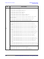
Contents
1. Overview of Modulation Formats
APCO 25 . . . . . . . . . . . . . . . . . . . . . . . . . . . . . . . . . . . . . . . . . . . . . . . . . . . . . . . . . . . . . . . . . . . . .1-2
Bluetooth. . . . . . . . . . . . . . . . . . . . . . . . . . . . . . . . . . . . . . . . . . . . . . . . . . . . . . . . . . . . . . . . . . . . .1-3
CDPD . . . . . . . . . . . . . . . . . . . . . . . . . . . . . . . . . . . . . . . . . . . . . . . . . . . . . . . . . . . . . . . . . . . . . . .1-4
Custom . . . . . . . . . . . . . . . . . . . . . . . . . . . . . . . . . . . . . . . . . . . . . . . . . . . . . . . . . . . . . . . . . . . . . .1-5
DECT . . . . . . . . . . . . . . . . . . . . . . . . . . . . . . . . . . . . . . . . . . . . . . . . . . . . . . . . . . . . . . . . . . . . . . .1-6
EDGE (Option 202 Only) . . . . . . . . . . . . . . . . . . . . . . . . . . . . . . . . . . . . . . . . . . . . . . . . . . . . . . . .1-7
GSM . . . . . . . . . . . . . . . . . . . . . . . . . . . . . . . . . . . . . . . . . . . . . . . . . . . . . . . . . . . . . . . . . . . . . . . .1-8
NADC . . . . . . . . . . . . . . . . . . . . . . . . . . . . . . . . . . . . . . . . . . . . . . . . . . . . . . . . . . . . . . . . . . . . . . .1-9
PDC . . . . . . . . . . . . . . . . . . . . . . . . . . . . . . . . . . . . . . . . . . . . . . . . . . . . . . . . . . . . . . . . . . . . . . . .1-10
PHS . . . . . . . . . . . . . . . . . . . . . . . . . . . . . . . . . . . . . . . . . . . . . . . . . . . . . . . . . . . . . . . . . . . . . . . .1-11
TETRA . . . . . . . . . . . . . . . . . . . . . . . . . . . . . . . . . . . . . . . . . . . . . . . . . . . . . . . . . . . . . . . . . . . . .1-12
2. Using Functions
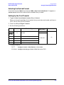
Setting Up Framed Digital Modulation . . . . . . . . . . . . . . . . . . . . . . . . . . . . . . . . . . . . . . . . . . . .2-2
Setting the Carrier Frequency . . . . . . . . . . . . . . . . . . . . . . . . . . . . . . . . . . . . . . . . . . . . . . . .2-2
Setting the Power Level. . . . . . . . . . . . . . . . . . . . . . . . . . . . . . . . . . . . . . . . . . . . . . . . . . . . . .2-2
Selecting the Desired Format . . . . . . . . . . . . . . . . . . . . . . . . . . . . . . . . . . . . . . . . . . . . . . . . .2-3
Setting Up the First Timeslot . . . . . . . . . . . . . . . . . . . . . . . . . . . . . . . . . . . . . . . . . . . . . . . . .2-3
Setting Up the Second Timeslot . . . . . . . . . . . . . . . . . . . . . . . . . . . . . . . . . . . . . . . . . . . . . . .2-4
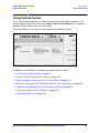
Using Custom Format . . . . . . . . . . . . . . . . . . . . . . . . . . . . . . . . . . . . . . . . . . . . . . . . . . . . . . . . . .2-5
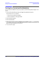
Turning On a Format and the Modulation . . . . . . . . . . . . . . . . . . . . . . . . . . . . . . . . . . . . . . . . . .2-6
Customizing the Burst Shape . . . . . . . . . . . . . . . . . . . . . . . . . . . . . . . . . . . . . . . . . . . . . . . . . . . .2-7
Changing Rise and Fall Times and Adding Delay . . . . . . . . . . . . . . . . . . . . . . . . . . . . . . . . .2-8
Defining the Shape of the Burst Curve . . . . . . . . . . . . . . . . . . . . . . . . . . . . . . . . . . . . . . . . .2-9
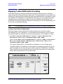
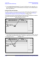
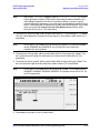
Mapping Custom Differential Encoding . . . . . . . . . . . . . . . . . . . . . . . . . . . . . . . . . . . . . . . . . . .2-11
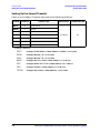
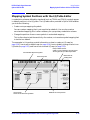
Mapping Symbol Positions with the I/Q Table Editor . . . . . . . . . . . . . . . . . . . . . . . . . . . . . . . .2-15
Creating a Symbol Map . . . . . . . . . . . . . . . . . . . . . . . . . . . . . . . . . . . . . . . . . . . . . . . . . . . . .2-16
Moving an I/Q Symbol . . . . . . . . . . . . . . . . . . . . . . . . . . . . . . . . . . . . . . . . . . . . . . . . . . . . . .2-19
Globally Replacing an I/Q Value . . . . . . . . . . . . . . . . . . . . . . . . . . . . . . . . . . . . . . . . . . . . . .2-21
Building a Customized FSK Modulation with the FSK Table Editor . . . . . . . . . . . . . . . . . . . .2-22
Choosing the Define User FSK Setting . . . . . . . . . . . . . . . . . . . . . . . . . . . . . . . . . . . . . . . .2-22
Creating a Unique FSK File of Frequency Deviations . . . . . . . . . . . . . . . . . . . . . . . . . . . .2-23
Modifying a Default FSK Pattern . . . . . . . . . . . . . . . . . . . . . . . . . . . . . . . . . . . . . . . . . . . . .2-24
Creating User-Defined FIR Filters . . . . . . . . . . . . . . . . . . . . . . . . . . . . . . . . . . . . . . . . . . . . . . .2-26
iii
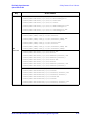
Contents
Creating a User-Defined FIR Filter by Entering Values . . . . . . . . . . . . . . . . . . . . . . . . . . 2-26
Modifying an Existing FIR Filter with the FIR Table Editor. . . . . . . . . . . . . . . . . . . . . . . 2-30
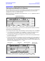
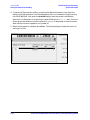
Storing User-Defined Files to Memory . . . . . . . . . . . . . . . . . . . . . . . . . . . . . . . . . . . . . . . . . . . . 2-33
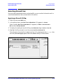
Selecting Stored Files . . . . . . . . . . . . . . . . . . . . . . . . . . . . . . . . . . . . . . . . . . . . . . . . . . . . . . . . . 2-35
Applying a Stored I/Q Map . . . . . . . . . . . . . . . . . . . . . . . . . . . . . . . . . . . . . . . . . . . . . . . . . . 2-35
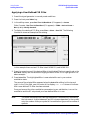
Applying a User-Defined FIR Filter. . . . . . . . . . . . . . . . . . . . . . . . . . . . . . . . . . . . . . . . . . . 2-36
Selecting a Custom FSK File . . . . . . . . . . . . . . . . . . . . . . . . . . . . . . . . . . . . . . . . . . . . . . . . 2-37
Using the Bit File Editor. . . . . . . . . . . . . . . . . . . . . . . . . . . . . . . . . . . . . . . . . . . . . . . . . . . . . . . 2-38
Creating a User File . . . . . . . . . . . . . . . . . . . . . . . . . . . . . . . . . . . . . . . . . . . . . . . . . . . . . . . 2-38
Modifying an Existing User File . . . . . . . . . . . . . . . . . . . . . . . . . . . . . . . . . . . . . . . . . . . . . 2-40
3. Softkey Reference
Symbols . . . . . . . . . . . . . . . . . . . . . . . . . . . . . . . . . . . . . . . . . . . . . . . . . . . . . . . . . . . . . . . . . . . . . 3-2
%. . . . . . . . . . . . . . . . . . . . . . . . . . . . . . . . . . . . . . . . . . . . . . . . . . . . . . . . . . . . . . . . . . . . . . . . 3-2
p/4 DQPSK. . . . . . . . . . . . . . . . . . . . . . . . . . . . . . . . . . . . . . . . . . . . . . . . . . . . . . . . . . . . . . . . 3-2
Numerics . . . . . . . . . . . . . . . . . . . . . . . . . . . . . . . . . . . . . . . . . . . . . . . . . . . . . . . . . . . . . . . . . . . . 3-3
2–Lvl FSK . . . . . . . . . . . . . . . . . . . . . . . . . . . . . . . . . . . . . . . . . . . . . . . . . . . . . . . . . . . . . . . . 3-3
3-Bit Sync . . . . . . . . . . . . . . . . . . . . . . . . . . . . . . . . . . . . . . . . . . . . . . . . . . . . . . . . . . . . . . . . 3-3
4 1’s & 4 0’s . . . . . . . . . . . . . . . . . . . . . . . . . . . . . . . . . . . . . . . . . . . . . . . . . . . . . . . . . . . . . . . 3-4
4-Lvl FSK. . . . . . . . . . . . . . . . . . . . . . . . . . . . . . . . . . . . . . . . . . . . . . . . . . . . . . . . . . . . . . . . . 3-5
4QAM. . . . . . . . . . . . . . . . . . . . . . . . . . . . . . . . . . . . . . . . . . . . . . . . . . . . . . . . . . . . . . . . . . . . 3-6
8 1’s & 8 0’s . . . . . . . . . . . . . . . . . . . . . . . . . . . . . . . . . . . . . . . . . . . . . . . . . . . . . . . . . . . . . . . 3-6
8-Lvl FSK. . . . . . . . . . . . . . . . . . . . . . . . . . . . . . . . . . . . . . . . . . . . . . . . . . . . . . . . . . . . . . . . . 3-8
8PSK . . . . . . . . . . . . . . . . . . . . . . . . . . . . . . . . . . . . . . . . . . . . . . . . . . . . . . . . . . . . . . . . . . . . 3-9
16 1’s & 16 0’s . . . . . . . . . . . . . . . . . . . . . . . . . . . . . . . . . . . . . . . . . . . . . . . . . . . . . . . . . . . . . 3-9
16–Lvl FSK . . . . . . . . . . . . . . . . . . . . . . . . . . . . . . . . . . . . . . . . . . . . . . . . . . . . . . . . . . . . . . 3-11
16PSK . . . . . . . . . . . . . . . . . . . . . . . . . . . . . . . . . . . . . . . . . . . . . . . . . . . . . . . . . . . . . . . . . . 3-11
16QAM. . . . . . . . . . . . . . . . . . . . . . . . . . . . . . . . . . . . . . . . . . . . . . . . . . . . . . . . . . . . . . . . . . 3-12
32 1’s & 32 0’s . . . . . . . . . . . . . . . . . . . . . . . . . . . . . . . . . . . . . . . . . . . . . . . . . . . . . . . . . . . . 3-13
32QAM. . . . . . . . . . . . . . . . . . . . . . . . . . . . . . . . . . . . . . . . . . . . . . . . . . . . . . . . . . . . . . . . . . 3-14
64 1’s & 64 0’s . . . . . . . . . . . . . . . . . . . . . . . . . . . . . . . . . . . . . . . . . . . . . . . . . . . . . . . . . . . . 3-15
64QAM. . . . . . . . . . . . . . . . . . . . . . . . . . . . . . . . . . . . . . . . . . . . . . . . . . . . . . . . . . . . . . . . . . 3-16
256QAM. . . . . . . . . . . . . . . . . . . . . . . . . . . . . . . . . . . . . . . . . . . . . . . . . . . . . . . . . . . . . . . . . 3-17
800 MHz Base . . . . . . . . . . . . . . . . . . . . . . . . . . . . . . . . . . . . . . . . . . . . . . . . . . . . . . . . . . . . 3-17
800 MHz Mobile . . . . . . . . . . . . . . . . . . . . . . . . . . . . . . . . . . . . . . . . . . . . . . . . . . . . . . . . . . 3-18
1500 MHz Base . . . . . . . . . . . . . . . . . . . . . . . . . . . . . . . . . . . . . . . . . . . . . . . . . . . . . . . . . . . 3-18
1500 MHz Mobile . . . . . . . . . . . . . . . . . . . . . . . . . . . . . . . . . . . . . . . . . . . . . . . . . . . . . . . . . 3-18
iv
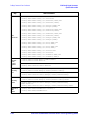
Contents
A . . . . . . . . . . . . . . . . . . . . . . . . . . . . . . . . . . . . . . . . . . . . . . . . . . . . . . . . . . . . . . . . . . . . . . . . . .3-19
A field . . . . . . . . . . . . . . . . . . . . . . . . . . . . . . . . . . . . . . . . . . . . . . . . . . . . . . . . . . . . . . . . . . .3-19
Access . . . . . . . . . . . . . . . . . . . . . . . . . . . . . . . . . . . . . . . . . . . . . . . . . . . . . . . . . . . . . . . . . . .3-19
All Timeslots . . . . . . . . . . . . . . . . . . . . . . . . . . . . . . . . . . . . . . . . . . . . . . . . . . . . . . . . . . . . .3-19
APCO 25 C4FM . . . . . . . . . . . . . . . . . . . . . . . . . . . . . . . . . . . . . . . . . . . . . . . . . . . . . . . . . . .3-20
APCO 25 w/C4FM . . . . . . . . . . . . . . . . . . . . . . . . . . . . . . . . . . . . . . . . . . . . . . . . . . . . . . . . .3-20
APCO 25 w/CQPSK . . . . . . . . . . . . . . . . . . . . . . . . . . . . . . . . . . . . . . . . . . . . . . . . . . . . . . . .3-20
B . . . . . . . . . . . . . . . . . . . . . . . . . . . . . . . . . . . . . . . . . . . . . . . . . . . . . . . . . . . . . . . . . . . . . . . . . .3-21
B . . . . . . . . . . . . . . . . . . . . . . . . . . . . . . . . . . . . . . . . . . . . . . . . . . . . . . . . . . . . . . . . . . . . . . .3-21
B field . . . . . . . . . . . . . . . . . . . . . . . . . . . . . . . . . . . . . . . . . . . . . . . . . . . . . . . . . . . . . . . . . . .3-21
B1 . . . . . . . . . . . . . . . . . . . . . . . . . . . . . . . . . . . . . . . . . . . . . . . . . . . . . . . . . . . . . . . . . . . . . .3-21
B2 . . . . . . . . . . . . . . . . . . . . . . . . . . . . . . . . . . . . . . . . . . . . . . . . . . . . . . . . . . . . . . . . . . . . . .3-22
Base . . . . . . . . . . . . . . . . . . . . . . . . . . . . . . . . . . . . . . . . . . . . . . . . . . . . . . . . . . . . . . . . . . . .3-22
BBG Data Clock Ext Int . . . . . . . . . . . . . . . . . . . . . . . . . . . . . . . . . . . . . . . . . . . . . . . . . . . .3-22
Begin Frame. . . . . . . . . . . . . . . . . . . . . . . . . . . . . . . . . . . . . . . . . . . . . . . . . . . . . . . . . . . . . .3-22
Begin Pattern . . . . . . . . . . . . . . . . . . . . . . . . . . . . . . . . . . . . . . . . . . . . . . . . . . . . . . . . . . . . .3-23
Begin Timeslot . . . . . . . . . . . . . . . . . . . . . . . . . . . . . . . . . . . . . . . . . . . . . . . . . . . . . . . . . . . .3-23
Beta. . . . . . . . . . . . . . . . . . . . . . . . . . . . . . . . . . . . . . . . . . . . . . . . . . . . . . . . . . . . . . . . . . . . .3-24
Bit Clock . . . . . . . . . . . . . . . . . . . . . . . . . . . . . . . . . . . . . . . . . . . . . . . . . . . . . . . . . . . . . . . . .3-24
Bluetooth . . . . . . . . . . . . . . . . . . . . . . . . . . . . . . . . . . . . . . . . . . . . . . . . . . . . . . . . . . . . . . . .3-24
BNC MUX Settings . . . . . . . . . . . . . . . . . . . . . . . . . . . . . . . . . . . . . . . . . . . . . . . . . . . . . . . .3-24
BPSK . . . . . . . . . . . . . . . . . . . . . . . . . . . . . . . . . . . . . . . . . . . . . . . . . . . . . . . . . . . . . . . . . . .3-24
Burst Shape . . . . . . . . . . . . . . . . . . . . . . . . . . . . . . . . . . . . . . . . . . . . . . . . . . . . . . . . . . . . . .3-25
Burst Shape Type . . . . . . . . . . . . . . . . . . . . . . . . . . . . . . . . . . . . . . . . . . . . . . . . . . . . . . . . .3-25
Bus . . . . . . . . . . . . . . . . . . . . . . . . . . . . . . . . . . . . . . . . . . . . . . . . . . . . . . . . . . . . . . . . . . . . .3-26
C . . . . . . . . . . . . . . . . . . . . . . . . . . . . . . . . . . . . . . . . . . . . . . . . . . . . . . . . . . . . . . . . . . . . . . . . . .3-27
C4FM . . . . . . . . . . . . . . . . . . . . . . . . . . . . . . . . . . . . . . . . . . . . . . . . . . . . . . . . . . . . . . . . . . .3-27
CC . . . . . . . . . . . . . . . . . . . . . . . . . . . . . . . . . . . . . . . . . . . . . . . . . . . . . . . . . . . . . . . . . . . . . .3-28
CDPD . . . . . . . . . . . . . . . . . . . . . . . . . . . . . . . . . . . . . . . . . . . . . . . . . . . . . . . . . . . . . . . . . . .3-28
CDVCC . . . . . . . . . . . . . . . . . . . . . . . . . . . . . . . . . . . . . . . . . . . . . . . . . . . . . . . . . . . . . . . . . .3-28
CS-1 . . . . . . . . . . . . . . . . . . . . . . . . . . . . . . . . . . . . . . . . . . . . . . . . . . . . . . . . . . . . . . . . . . . .3-28
Channel Band . . . . . . . . . . . . . . . . . . . . . . . . . . . . . . . . . . . . . . . . . . . . . . . . . . . . . . . . . . . .3-28
Channel Number . . . . . . . . . . . . . . . . . . . . . . . . . . . . . . . . . . . . . . . . . . . . . . . . . . . . . . . . . .3-29
Configure Access . . . . . . . . . . . . . . . . . . . . . . . . . . . . . . . . . . . . . . . . . . . . . . . . . . . . . . . . . .3-29
Configure Custom . . . . . . . . . . . . . . . . . . . . . . . . . . . . . . . . . . . . . . . . . . . . . . . . . . . . . . . . .3-30
Configure Differential Encoding . . . . . . . . . . . . . . . . . . . . . . . . . . . . . . . . . . . . . . . . . . . . . .3-31
Configure Dn Custom Cont . . . . . . . . . . . . . . . . . . . . . . . . . . . . . . . . . . . . . . . . . . . . . . . . . .3-32
v
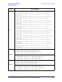
Contents
Configure Dn Custom Disc . . . . . . . . . . . . . . . . . . . . . . . . . . . . . . . . . . . . . . . . . . . . . . . . . . 3-33
Configure Dn Normal Cont. . . . . . . . . . . . . . . . . . . . . . . . . . . . . . . . . . . . . . . . . . . . . . . . . . 3-34
Configure Dn Normal Disc . . . . . . . . . . . . . . . . . . . . . . . . . . . . . . . . . . . . . . . . . . . . . . . . . . 3-35
Configure Dn Sync Cont . . . . . . . . . . . . . . . . . . . . . . . . . . . . . . . . . . . . . . . . . . . . . . . . . . . . 3-36
Configure Dn Sync Disc . . . . . . . . . . . . . . . . . . . . . . . . . . . . . . . . . . . . . . . . . . . . . . . . . . . . 3-37
Configure Down Custom . . . . . . . . . . . . . . . . . . . . . . . . . . . . . . . . . . . . . . . . . . . . . . . . . . . . 3-38
Configure Down TCH . . . . . . . . . . . . . . . . . . . . . . . . . . . . . . . . . . . . . . . . . . . . . . . . . . . . . . 3-39
Configure Dummy . . . . . . . . . . . . . . . . . . . . . . . . . . . . . . . . . . . . . . . . . . . . . . . . . . . . . . . . . 3-41
Configure Dummy Bearer 1 . . . . . . . . . . . . . . . . . . . . . . . . . . . . . . . . . . . . . . . . . . . . . . . . . 3-42
Configure Dummy Bearer 2 . . . . . . . . . . . . . . . . . . . . . . . . . . . . . . . . . . . . . . . . . . . . . . . . . 3-43
Configure FCorr . . . . . . . . . . . . . . . . . . . . . . . . . . . . . . . . . . . . . . . . . . . . . . . . . . . . . . . . . . 3-44
Configure Frame . . . . . . . . . . . . . . . . . . . . . . . . . . . . . . . . . . . . . . . . . . . . . . . . . . . . . . . . . . 3-45
Configure Hardware . . . . . . . . . . . . . . . . . . . . . . . . . . . . . . . . . . . . . . . . . . . . . . . . . . . . . . . 3-45
Configure Low Capacity . . . . . . . . . . . . . . . . . . . . . . . . . . . . . . . . . . . . . . . . . . . . . . . . . . . . 3-45
Configure Low Capacity with Z Field . . . . . . . . . . . . . . . . . . . . . . . . . . . . . . . . . . . . . . . . . 3-46
Configure Normal . . . . . . . . . . . . . . . . . . . . . . . . . . . . . . . . . . . . . . . . . . . . . . . . . . . . . . . . . 3-47
Configure Sync . . . . . . . . . . . . . . . . . . . . . . . . . . . . . . . . . . . . . . . . . . . . . . . . . . . . . . . . . . . 3-50
Configure TCH . . . . . . . . . . . . . . . . . . . . . . . . . . . . . . . . . . . . . . . . . . . . . . . . . . . . . . . . . . . 3-52
Configure Timeslots . . . . . . . . . . . . . . . . . . . . . . . . . . . . . . . . . . . . . . . . . . . . . . . . . . . . . . . 3-53
Configure Traffic Bearer . . . . . . . . . . . . . . . . . . . . . . . . . . . . . . . . . . . . . . . . . . . . . . . . . . . . 3-54
Configure Traffic Bearer with Z Field . . . . . . . . . . . . . . . . . . . . . . . . . . . . . . . . . . . . . . . . . 3-55
Configure Up Control 1. . . . . . . . . . . . . . . . . . . . . . . . . . . . . . . . . . . . . . . . . . . . . . . . . . . . . 3-56
Configure Up Control 2. . . . . . . . . . . . . . . . . . . . . . . . . . . . . . . . . . . . . . . . . . . . . . . . . . . . . 3-57
Configure Up Custom . . . . . . . . . . . . . . . . . . . . . . . . . . . . . . . . . . . . . . . . . . . . . . . . . . . . . . 3-58
Configure Up Normal . . . . . . . . . . . . . . . . . . . . . . . . . . . . . . . . . . . . . . . . . . . . . . . . . . . . . . 3-59
Configure Up TCH . . . . . . . . . . . . . . . . . . . . . . . . . . . . . . . . . . . . . . . . . . . . . . . . . . . . . . . . 3-60
Configure Up VOX . . . . . . . . . . . . . . . . . . . . . . . . . . . . . . . . . . . . . . . . . . . . . . . . . . . . . . . . 3-62
Control Channel Dnlink Uplink. . . . . . . . . . . . . . . . . . . . . . . . . . . . . . . . . . . . . . . . . . . . . . 3-63
Copy File . . . . . . . . . . . . . . . . . . . . . . . . . . . . . . . . . . . . . . . . . . . . . . . . . . . . . . . . . . . . . . . . 3-63
Create a File . . . . . . . . . . . . . . . . . . . . . . . . . . . . . . . . . . . . . . . . . . . . . . . . . . . . . . . . . . . . . 3-63
CSID. . . . . . . . . . . . . . . . . . . . . . . . . . . . . . . . . . . . . . . . . . . . . . . . . . . . . . . . . . . . . . . . . . . . 3-63
Custom. . . . . . . . . . . . . . . . . . . . . . . . . . . . . . . . . . . . . . . . . . . . . . . . . . . . . . . . . . . . . . . . . . 3-64
Custom Off On. . . . . . . . . . . . . . . . . . . . . . . . . . . . . . . . . . . . . . . . . . . . . . . . . . . . . . . . . . . . 3-64
Custom TS . . . . . . . . . . . . . . . . . . . . . . . . . . . . . . . . . . . . . . . . . . . . . . . . . . . . . . . . . . . . . . . 3-65
D . . . . . . . . . . . . . . . . . . . . . . . . . . . . . . . . . . . . . . . . . . . . . . . . . . . . . . . . . . . . . . . . . . . . . . . . . . 3-66
D8PSK . . . . . . . . . . . . . . . . . . . . . . . . . . . . . . . . . . . . . . . . . . . . . . . . . . . . . . . . . . . . . . . . . . 3-66
Data . . . . . . . . . . . . . . . . . . . . . . . . . . . . . . . . . . . . . . . . . . . . . . . . . . . . . . . . . . . . . . . . . . . . 3-66
vi
Contents
Data Format Pattern Framed . . . . . . . . . . . . . . . . . . . . . . . . . . . . . . . . . . . . . . . . . . . . . . . .3-68
Data Clk Out . . . . . . . . . . . . . . . . . . . . . . . . . . . . . . . . . . . . . . . . . . . . . . . . . . . . . . . . . . . . .3-69
Data Out. . . . . . . . . . . . . . . . . . . . . . . . . . . . . . . . . . . . . . . . . . . . . . . . . . . . . . . . . . . . . . . . .3-70
DCS Base . . . . . . . . . . . . . . . . . . . . . . . . . . . . . . . . . . . . . . . . . . . . . . . . . . . . . . . . . . . . . . . .3-70
DCS Mobile . . . . . . . . . . . . . . . . . . . . . . . . . . . . . . . . . . . . . . . . . . . . . . . . . . . . . . . . . . . . . .3-70
DECT . . . . . . . . . . . . . . . . . . . . . . . . . . . . . . . . . . . . . . . . . . . . . . . . . . . . . . . . . . . . . . . . . . .3-70
DECT Off On . . . . . . . . . . . . . . . . . . . . . . . . . . . . . . . . . . . . . . . . . . . . . . . . . . . . . . . . . . . . .3-70
Dect Patterns . . . . . . . . . . . . . . . . . . . . . . . . . . . . . . . . . . . . . . . . . . . . . . . . . . . . . . . . . . . . .3-70
Define User Burst Shape. . . . . . . . . . . . . . . . . . . . . . . . . . . . . . . . . . . . . . . . . . . . . . . . . . . .3-71
Define User FIR . . . . . . . . . . . . . . . . . . . . . . . . . . . . . . . . . . . . . . . . . . . . . . . . . . . . . . . . . . .3-71
Define User FSK . . . . . . . . . . . . . . . . . . . . . . . . . . . . . . . . . . . . . . . . . . . . . . . . . . . . . . . . . .3-72
Define User I/Q . . . . . . . . . . . . . . . . . . . . . . . . . . . . . . . . . . . . . . . . . . . . . . . . . . . . . . . . . . .3-72
Delete . . . . . . . . . . . . . . . . . . . . . . . . . . . . . . . . . . . . . . . . . . . . . . . . . . . . . . . . . . . . . . . . . . .3-72
Delete All Rows . . . . . . . . . . . . . . . . . . . . . . . . . . . . . . . . . . . . . . . . . . . . . . . . . . . . . . . . . . .3-72
Delete Bits . . . . . . . . . . . . . . . . . . . . . . . . . . . . . . . . . . . . . . . . . . . . . . . . . . . . . . . . . . . . . . .3-73
Delete Row . . . . . . . . . . . . . . . . . . . . . . . . . . . . . . . . . . . . . . . . . . . . . . . . . . . . . . . . . . . . . . .3-73
Delete to Beginning . . . . . . . . . . . . . . . . . . . . . . . . . . . . . . . . . . . . . . . . . . . . . . . . . . . . . . . .3-73
Delete to End . . . . . . . . . . . . . . . . . . . . . . . . . . . . . . . . . . . . . . . . . . . . . . . . . . . . . . . . . . . . .3-73
Diff Data Encode Off On . . . . . . . . . . . . . . . . . . . . . . . . . . . . . . . . . . . . . . . . . . . . . . . . . . . .3-73
Differential Encoding Off On . . . . . . . . . . . . . . . . . . . . . . . . . . . . . . . . . . . . . . . . . . . . . . . .3-73
Display Burst Shape . . . . . . . . . . . . . . . . . . . . . . . . . . . . . . . . . . . . . . . . . . . . . . . . . . . . . . .3-74
Display FFT . . . . . . . . . . . . . . . . . . . . . . . . . . . . . . . . . . . . . . . . . . . . . . . . . . . . . . . . . . . . . .3-74
Display Impulse Response. . . . . . . . . . . . . . . . . . . . . . . . . . . . . . . . . . . . . . . . . . . . . . . . . . .3-75
Display I/Q Map . . . . . . . . . . . . . . . . . . . . . . . . . . . . . . . . . . . . . . . . . . . . . . . . . . . . . . . . . . .3-75
DM0 . . . . . . . . . . . . . . . . . . . . . . . . . . . . . . . . . . . . . . . . . . . . . . . . . . . . . . . . . . . . . . . . . . . .3-76
DM1 . . . . . . . . . . . . . . . . . . . . . . . . . . . . . . . . . . . . . . . . . . . . . . . . . . . . . . . . . . . . . . . . . . . .3-76
Dn Custom Cont. . . . . . . . . . . . . . . . . . . . . . . . . . . . . . . . . . . . . . . . . . . . . . . . . . . . . . . . . . .3-76
Dn Custom Disc . . . . . . . . . . . . . . . . . . . . . . . . . . . . . . . . . . . . . . . . . . . . . . . . . . . . . . . . . . .3-77
Dn Normal Cont. . . . . . . . . . . . . . . . . . . . . . . . . . . . . . . . . . . . . . . . . . . . . . . . . . . . . . . . . . .3-77
Dn Normal Disc . . . . . . . . . . . . . . . . . . . . . . . . . . . . . . . . . . . . . . . . . . . . . . . . . . . . . . . . . . .3-78
Dn Sync Cont . . . . . . . . . . . . . . . . . . . . . . . . . . . . . . . . . . . . . . . . . . . . . . . . . . . . . . . . . . . . .3-78
Dn Sync Disc . . . . . . . . . . . . . . . . . . . . . . . . . . . . . . . . . . . . . . . . . . . . . . . . . . . . . . . . . . . . .3-79
Down Custom . . . . . . . . . . . . . . . . . . . . . . . . . . . . . . . . . . . . . . . . . . . . . . . . . . . . . . . . . . . . .3-79
Downlink MCS-1 . . . . . . . . . . . . . . . . . . . . . . . . . . . . . . . . . . . . . . . . . . . . . . . . . . . . . . . . . .3-80
Downlink MCS-5 . . . . . . . . . . . . . . . . . . . . . . . . . . . . . . . . . . . . . . . . . . . . . . . . . . . . . . . . . .3-80
Downlink MCS-9 . . . . . . . . . . . . . . . . . . . . . . . . . . . . . . . . . . . . . . . . . . . . . . . . . . . . . . . . . .3-80
Down TCH . . . . . . . . . . . . . . . . . . . . . . . . . . . . . . . . . . . . . . . . . . . . . . . . . . . . . . . . . . . . . . .3-80
vii
Contents
Down TCH All . . . . . . . . . . . . . . . . . . . . . . . . . . . . . . . . . . . . . . . . . . . . . . . . . . . . . . . . . . . . 3-81
Dummy . . . . . . . . . . . . . . . . . . . . . . . . . . . . . . . . . . . . . . . . . . . . . . . . . . . . . . . . . . . . . . . . . 3-81
Dummy Bearer 1 . . . . . . . . . . . . . . . . . . . . . . . . . . . . . . . . . . . . . . . . . . . . . . . . . . . . . . . . . . 3-81
Dummy Bearer 2 . . . . . . . . . . . . . . . . . . . . . . . . . . . . . . . . . . . . . . . . . . . . . . . . . . . . . . . . . . 3-81
E . . . . . . . . . . . . . . . . . . . . . . . . . . . . . . . . . . . . . . . . . . . . . . . . . . . . . . . . . . . . . . . . . . . . . . . . . . 3-82
E . . . . . . . . . . . . . . . . . . . . . . . . . . . . . . . . . . . . . . . . . . . . . . . . . . . . . . . . . . . . . . . . . . . . . . . 3-82
E Field Data . . . . . . . . . . . . . . . . . . . . . . . . . . . . . . . . . . . . . . . . . . . . . . . . . . . . . . . . . . . . . 3-82
E-GSM Base . . . . . . . . . . . . . . . . . . . . . . . . . . . . . . . . . . . . . . . . . . . . . . . . . . . . . . . . . . . . . 3-82
E-GSM Mobile . . . . . . . . . . . . . . . . . . . . . . . . . . . . . . . . . . . . . . . . . . . . . . . . . . . . . . . . . . . . 3-82
E-TCH/F43.2 . . . . . . . . . . . . . . . . . . . . . . . . . . . . . . . . . . . . . . . . . . . . . . . . . . . . . . . . . . . . . 3-83
EDGE. . . . . . . . . . . . . . . . . . . . . . . . . . . . . . . . . . . . . . . . . . . . . . . . . . . . . . . . . . . . . . . . . . . 3-83
EDGE (Rev 8.3.0 Release 1999) . . . . . . . . . . . . . . . . . . . . . . . . . . . . . . . . . . . . . . . . . . . . . . 3-83
EDGE Off On. . . . . . . . . . . . . . . . . . . . . . . . . . . . . . . . . . . . . . . . . . . . . . . . . . . . . . . . . . . . . 3-83
Edit Fall Shape . . . . . . . . . . . . . . . . . . . . . . . . . . . . . . . . . . . . . . . . . . . . . . . . . . . . . . . . . . . 3-84
Edit File . . . . . . . . . . . . . . . . . . . . . . . . . . . . . . . . . . . . . . . . . . . . . . . . . . . . . . . . . . . . . . . . . 3-84
Editing Keys . . . . . . . . . . . . . . . . . . . . . . . . . . . . . . . . . . . . . . . . . . . . . . . . . . . . . . . . . . . . . 3-84
Edit Item . . . . . . . . . . . . . . . . . . . . . . . . . . . . . . . . . . . . . . . . . . . . . . . . . . . . . . . . . . . . . . . . 3-85
Edit Rise Shape . . . . . . . . . . . . . . . . . . . . . . . . . . . . . . . . . . . . . . . . . . . . . . . . . . . . . . . . . . . 3-85
ET. . . . . . . . . . . . . . . . . . . . . . . . . . . . . . . . . . . . . . . . . . . . . . . . . . . . . . . . . . . . . . . . . . . . . . 3-85
Event 1. . . . . . . . . . . . . . . . . . . . . . . . . . . . . . . . . . . . . . . . . . . . . . . . . . . . . . . . . . . . . . . . . . 3-85
Ext . . . . . . . . . . . . . . . . . . . . . . . . . . . . . . . . . . . . . . . . . . . . . . . . . . . . . . . . . . . . . . . . . . . . . 3-86
Ext Data Clock Normal Symbol . . . . . . . . . . . . . . . . . . . . . . . . . . . . . . . . . . . . . . . . . . . . . . 3-87
Ext Delay Bits . . . . . . . . . . . . . . . . . . . . . . . . . . . . . . . . . . . . . . . . . . . . . . . . . . . . . . . . . . . . 3-88
Ext Delay Off On . . . . . . . . . . . . . . . . . . . . . . . . . . . . . . . . . . . . . . . . . . . . . . . . . . . . . . . . . . 3-89
External 13 MHz Off On. . . . . . . . . . . . . . . . . . . . . . . . . . . . . . . . . . . . . . . . . . . . . . . . . . . . 3-89
F . . . . . . . . . . . . . . . . . . . . . . . . . . . . . . . . . . . . . . . . . . . . . . . . . . . . . . . . . . . . . . . . . . . . . . . . . . 3-90
FACC . . . . . . . . . . . . . . . . . . . . . . . . . . . . . . . . . . . . . . . . . . . . . . . . . . . . . . . . . . . . . . . . . . . 3-90
Fall Delay. . . . . . . . . . . . . . . . . . . . . . . . . . . . . . . . . . . . . . . . . . . . . . . . . . . . . . . . . . . . . . . . 3-90
Fall Time . . . . . . . . . . . . . . . . . . . . . . . . . . . . . . . . . . . . . . . . . . . . . . . . . . . . . . . . . . . . . . . . 3-91
FCOR . . . . . . . . . . . . . . . . . . . . . . . . . . . . . . . . . . . . . . . . . . . . . . . . . . . . . . . . . . . . . . . . . . . 3-91
FCorr . . . . . . . . . . . . . . . . . . . . . . . . . . . . . . . . . . . . . . . . . . . . . . . . . . . . . . . . . . . . . . . . . . . 3-91
FDEV1_FS. . . . . . . . . . . . . . . . . . . . . . . . . . . . . . . . . . . . . . . . . . . . . . . . . . . . . . . . . . . . . . . 3-92
FDEV1_HS . . . . . . . . . . . . . . . . . . . . . . . . . . . . . . . . . . . . . . . . . . . . . . . . . . . . . . . . . . . . . . 3-92
FDEV2_FS. . . . . . . . . . . . . . . . . . . . . . . . . . . . . . . . . . . . . . . . . . . . . . . . . . . . . . . . . . . . . . . 3-92
Filter . . . . . . . . . . . . . . . . . . . . . . . . . . . . . . . . . . . . . . . . . . . . . . . . . . . . . . . . . . . . . . . . . . . 3-93
Filter Alpha . . . . . . . . . . . . . . . . . . . . . . . . . . . . . . . . . . . . . . . . . . . . . . . . . . . . . . . . . . . . . . 3-93
Filter BbT . . . . . . . . . . . . . . . . . . . . . . . . . . . . . . . . . . . . . . . . . . . . . . . . . . . . . . . . . . . . . . . 3-94
viii
Contents
Filter Factor N/A . . . . . . . . . . . . . . . . . . . . . . . . . . . . . . . . . . . . . . . . . . . . . . . . . . . . . . . . . .3-95
Filter Symbols . . . . . . . . . . . . . . . . . . . . . . . . . . . . . . . . . . . . . . . . . . . . . . . . . . . . . . . . . . . .3-95
FIX4 . . . . . . . . . . . . . . . . . . . . . . . . . . . . . . . . . . . . . . . . . . . . . . . . . . . . . . . . . . . . . . . . . . . .3-96
Frame Repeat Single Cont . . . . . . . . . . . . . . . . . . . . . . . . . . . . . . . . . . . . . . . . . . . . . . . . . .3-97
Frame Trigger . . . . . . . . . . . . . . . . . . . . . . . . . . . . . . . . . . . . . . . . . . . . . . . . . . . . . . . . . . . .3-98
Freq Channels . . . . . . . . . . . . . . . . . . . . . . . . . . . . . . . . . . . . . . . . . . . . . . . . . . . . . . . . . . . .3-99
Freq Channels Off On . . . . . . . . . . . . . . . . . . . . . . . . . . . . . . . . . . . . . . . . . . . . . . . . . . . . . .3-99
Freq Dev . . . . . . . . . . . . . . . . . . . . . . . . . . . . . . . . . . . . . . . . . . . . . . . . . . . . . . . . . . . . . . . . .3-99
FSK . . . . . . . . . . . . . . . . . . . . . . . . . . . . . . . . . . . . . . . . . . . . . . . . . . . . . . . . . . . . . . . . . . . .3-100
G . . . . . . . . . . . . . . . . . . . . . . . . . . . . . . . . . . . . . . . . . . . . . . . . . . . . . . . . . . . . . . . . . . . . . . . . .3-101
G . . . . . . . . . . . . . . . . . . . . . . . . . . . . . . . . . . . . . . . . . . . . . . . . . . . . . . . . . . . . . . . . . . . . . .3-101
Gated . . . . . . . . . . . . . . . . . . . . . . . . . . . . . . . . . . . . . . . . . . . . . . . . . . . . . . . . . . . . . . . . . .3-101
Gated Clock . . . . . . . . . . . . . . . . . . . . . . . . . . . . . . . . . . . . . . . . . . . . . . . . . . . . . . . . . . . . .3-102
Gaussian. . . . . . . . . . . . . . . . . . . . . . . . . . . . . . . . . . . . . . . . . . . . . . . . . . . . . . . . . . . . . . . .3-102
Globally Replace Selected Item. . . . . . . . . . . . . . . . . . . . . . . . . . . . . . . . . . . . . . . . . . . . . .3-103
Goto Bottom Row . . . . . . . . . . . . . . . . . . . . . . . . . . . . . . . . . . . . . . . . . . . . . . . . . . . . . . . . .3-103
Goto Middle Row . . . . . . . . . . . . . . . . . . . . . . . . . . . . . . . . . . . . . . . . . . . . . . . . . . . . . . . . .3-103
Goto Row . . . . . . . . . . . . . . . . . . . . . . . . . . . . . . . . . . . . . . . . . . . . . . . . . . . . . . . . . . . . . . .3-103
Goto Top Row . . . . . . . . . . . . . . . . . . . . . . . . . . . . . . . . . . . . . . . . . . . . . . . . . . . . . . . . . . . .3-103
Gray Coded QPSK . . . . . . . . . . . . . . . . . . . . . . . . . . . . . . . . . . . . . . . . . . . . . . . . . . . . . . . .3-104
GSM . . . . . . . . . . . . . . . . . . . . . . . . . . . . . . . . . . . . . . . . . . . . . . . . . . . . . . . . . . . . . . . . . . .3-104
GSM 450 Base . . . . . . . . . . . . . . . . . . . . . . . . . . . . . . . . . . . . . . . . . . . . . . . . . . . . . . . . . . .3-104
GSM 450 Mobile. . . . . . . . . . . . . . . . . . . . . . . . . . . . . . . . . . . . . . . . . . . . . . . . . . . . . . . . . .3-105
GSM 450/850 Base . . . . . . . . . . . . . . . . . . . . . . . . . . . . . . . . . . . . . . . . . . . . . . . . . . . . . . . .3-105
GSM 450/850 Mobile . . . . . . . . . . . . . . . . . . . . . . . . . . . . . . . . . . . . . . . . . . . . . . . . . . . . . .3-105
GSM 480 Base . . . . . . . . . . . . . . . . . . . . . . . . . . . . . . . . . . . . . . . . . . . . . . . . . . . . . . . . . . .3-105
GSM 480 Mobile. . . . . . . . . . . . . . . . . . . . . . . . . . . . . . . . . . . . . . . . . . . . . . . . . . . . . . . . . .3-105
GSM 850 Base . . . . . . . . . . . . . . . . . . . . . . . . . . . . . . . . . . . . . . . . . . . . . . . . . . . . . . . . . . .3-105
GSM 850 Mobile. . . . . . . . . . . . . . . . . . . . . . . . . . . . . . . . . . . . . . . . . . . . . . . . . . . . . . . . . .3-106
GSM Off On . . . . . . . . . . . . . . . . . . . . . . . . . . . . . . . . . . . . . . . . . . . . . . . . . . . . . . . . . . . . .3-106
H . . . . . . . . . . . . . . . . . . . . . . . . . . . . . . . . . . . . . . . . . . . . . . . . . . . . . . . . . . . . . . . . . . . . . . . . .3-107
Hamming . . . . . . . . . . . . . . . . . . . . . . . . . . . . . . . . . . . . . . . . . . . . . . . . . . . . . . . . . . . . . . .3-107
Hann . . . . . . . . . . . . . . . . . . . . . . . . . . . . . . . . . . . . . . . . . . . . . . . . . . . . . . . . . . . . . . . . . . .3-107
I . . . . . . . . . . . . . . . . . . . . . . . . . . . . . . . . . . . . . . . . . . . . . . . . . . . . . . . . . . . . . . . . . . . . . . . . . .3-108
IDLE . . . . . . . . . . . . . . . . . . . . . . . . . . . . . . . . . . . . . . . . . . . . . . . . . . . . . . . . . . . . . . . . . . .3-108
Insert . . . . . . . . . . . . . . . . . . . . . . . . . . . . . . . . . . . . . . . . . . . . . . . . . . . . . . . . . . . . . . . . . .3-108
Insert 1’s . . . . . . . . . . . . . . . . . . . . . . . . . . . . . . . . . . . . . . . . . . . . . . . . . . . . . . . . . . . . . . . .3-108
ix
Contents
Insert 0’s . . . . . . . . . . . . . . . . . . . . . . . . . . . . . . . . . . . . . . . . . . . . . . . . . . . . . . . . . . . . . . . 3-108
Insert Row . . . . . . . . . . . . . . . . . . . . . . . . . . . . . . . . . . . . . . . . . . . . . . . . . . . . . . . . . . . . . . 3-108
Interleave Gating . . . . . . . . . . . . . . . . . . . . . . . . . . . . . . . . . . . . . . . . . . . . . . . . . . . . . . . . 3-108
I/Q Scaling . . . . . . . . . . . . . . . . . . . . . . . . . . . . . . . . . . . . . . . . . . . . . . . . . . . . . . . . . . . . . . 3-109
IS-95. . . . . . . . . . . . . . . . . . . . . . . . . . . . . . . . . . . . . . . . . . . . . . . . . . . . . . . . . . . . . . . . . . . 3-109
IS-95 and IS-2000 . . . . . . . . . . . . . . . . . . . . . . . . . . . . . . . . . . . . . . . . . . . . . . . . . . . . . . . . 3-109
IS-95 Mod . . . . . . . . . . . . . . . . . . . . . . . . . . . . . . . . . . . . . . . . . . . . . . . . . . . . . . . . . . . . . . 3-109
IS-95 w/EQ. . . . . . . . . . . . . . . . . . . . . . . . . . . . . . . . . . . . . . . . . . . . . . . . . . . . . . . . . . . . . . 3-110
IS-95 Mod w/EQ . . . . . . . . . . . . . . . . . . . . . . . . . . . . . . . . . . . . . . . . . . . . . . . . . . . . . . . . . 3-110
IS95 OQPSK . . . . . . . . . . . . . . . . . . . . . . . . . . . . . . . . . . . . . . . . . . . . . . . . . . . . . . . . . . . . 3-110
IS95 QPSK. . . . . . . . . . . . . . . . . . . . . . . . . . . . . . . . . . . . . . . . . . . . . . . . . . . . . . . . . . . . . . 3-111
K . . . . . . . . . . . . . . . . . . . . . . . . . . . . . . . . . . . . . . . . . . . . . . . . . . . . . . . . . . . . . . . . . . . . . . . . . 3-112
Kaiser. . . . . . . . . . . . . . . . . . . . . . . . . . . . . . . . . . . . . . . . . . . . . . . . . . . . . . . . . . . . . . . . . . 3-112
L . . . . . . . . . . . . . . . . . . . . . . . . . . . . . . . . . . . . . . . . . . . . . . . . . . . . . . . . . . . . . . . . . . . . . . . . . 3-113
Load Default FIR . . . . . . . . . . . . . . . . . . . . . . . . . . . . . . . . . . . . . . . . . . . . . . . . . . . . . . . . 3-113
Load Default FSK . . . . . . . . . . . . . . . . . . . . . . . . . . . . . . . . . . . . . . . . . . . . . . . . . . . . . . . . 3-113
Load Default I/Q Map . . . . . . . . . . . . . . . . . . . . . . . . . . . . . . . . . . . . . . . . . . . . . . . . . . . . . 3-113
Load From Selected File . . . . . . . . . . . . . . . . . . . . . . . . . . . . . . . . . . . . . . . . . . . . . . . . . . . 3-113
Load Mirror Image of Fall Shape . . . . . . . . . . . . . . . . . . . . . . . . . . . . . . . . . . . . . . . . . . . . 3-114
Load Mirror Image of Rise Shape . . . . . . . . . . . . . . . . . . . . . . . . . . . . . . . . . . . . . . . . . . . 3-114
Load/Store . . . . . . . . . . . . . . . . . . . . . . . . . . . . . . . . . . . . . . . . . . . . . . . . . . . . . . . . . . . . . . 3-114
Low Capacity . . . . . . . . . . . . . . . . . . . . . . . . . . . . . . . . . . . . . . . . . . . . . . . . . . . . . . . . . . . . 3-115
Low Capacity with Z Field . . . . . . . . . . . . . . . . . . . . . . . . . . . . . . . . . . . . . . . . . . . . . . . . . 3-115
M. . . . . . . . . . . . . . . . . . . . . . . . . . . . . . . . . . . . . . . . . . . . . . . . . . . . . . . . . . . . . . . . . . . . . . . . . 3-116
Manual Reset & Run. . . . . . . . . . . . . . . . . . . . . . . . . . . . . . . . . . . . . . . . . . . . . . . . . . . . . . 3-116
Mirror Table . . . . . . . . . . . . . . . . . . . . . . . . . . . . . . . . . . . . . . . . . . . . . . . . . . . . . . . . . . . . 3-116
Mobile . . . . . . . . . . . . . . . . . . . . . . . . . . . . . . . . . . . . . . . . . . . . . . . . . . . . . . . . . . . . . . . . . 3-116
Modify Standard . . . . . . . . . . . . . . . . . . . . . . . . . . . . . . . . . . . . . . . . . . . . . . . . . . . . . . . . . 3-116
Modulation Type . . . . . . . . . . . . . . . . . . . . . . . . . . . . . . . . . . . . . . . . . . . . . . . . . . . . . . . . . 3-117
More . . . . . . . . . . . . . . . . . . . . . . . . . . . . . . . . . . . . . . . . . . . . . . . . . . . . . . . . . . . . . . . . . . . 3-117
MSK . . . . . . . . . . . . . . . . . . . . . . . . . . . . . . . . . . . . . . . . . . . . . . . . . . . . . . . . . . . . . . . . . . . 3-117
Multiframe Channel . . . . . . . . . . . . . . . . . . . . . . . . . . . . . . . . . . . . . . . . . . . . . . . . . . . . . . 3-118
Multiframe Data . . . . . . . . . . . . . . . . . . . . . . . . . . . . . . . . . . . . . . . . . . . . . . . . . . . . . . . . . 3-118
Multiframe Trigger . . . . . . . . . . . . . . . . . . . . . . . . . . . . . . . . . . . . . . . . . . . . . . . . . . . . . . . 3-118
N . . . . . . . . . . . . . . . . . . . . . . . . . . . . . . . . . . . . . . . . . . . . . . . . . . . . . . . . . . . . . . . . . . . . . . . . . 3-119
NADC. . . . . . . . . . . . . . . . . . . . . . . . . . . . . . . . . . . . . . . . . . . . . . . . . . . . . . . . . . . . . . . . . . 3-119
NADC Off On. . . . . . . . . . . . . . . . . . . . . . . . . . . . . . . . . . . . . . . . . . . . . . . . . . . . . . . . . . . . 3-119
x
Contents
None . . . . . . . . . . . . . . . . . . . . . . . . . . . . . . . . . . . . . . . . . . . . . . . . . . . . . . . . . . . . . . . . . . .3-119
Normal . . . . . . . . . . . . . . . . . . . . . . . . . . . . . . . . . . . . . . . . . . . . . . . . . . . . . . . . . . . . . . . . .3-120
Normal All . . . . . . . . . . . . . . . . . . . . . . . . . . . . . . . . . . . . . . . . . . . . . . . . . . . . . . . . . . . . . .3-120
Number of Bits . . . . . . . . . . . . . . . . . . . . . . . . . . . . . . . . . . . . . . . . . . . . . . . . . . . . . . . . . . .3-120
Nyquist . . . . . . . . . . . . . . . . . . . . . . . . . . . . . . . . . . . . . . . . . . . . . . . . . . . . . . . . . . . . . . . . .3-120
O . . . . . . . . . . . . . . . . . . . . . . . . . . . . . . . . . . . . . . . . . . . . . . . . . . . . . . . . . . . . . . . . . . . . . . . . .3-122
Offset Q Off On . . . . . . . . . . . . . . . . . . . . . . . . . . . . . . . . . . . . . . . . . . . . . . . . . . . . . . . . . .3-122
Optimize FIR For EVM ACP . . . . . . . . . . . . . . . . . . . . . . . . . . . . . . . . . . . . . . . . . . . . . . . .3-122
OQPSK . . . . . . . . . . . . . . . . . . . . . . . . . . . . . . . . . . . . . . . . . . . . . . . . . . . . . . . . . . . . . . . . .3-123
Other Patterns . . . . . . . . . . . . . . . . . . . . . . . . . . . . . . . . . . . . . . . . . . . . . . . . . . . . . . . . . . .3-124
Oversample Ratio . . . . . . . . . . . . . . . . . . . . . . . . . . . . . . . . . . . . . . . . . . . . . . . . . . . . . . . .3-125
P . . . . . . . . . . . . . . . . . . . . . . . . . . . . . . . . . . . . . . . . . . . . . . . . . . . . . . . . . . . . . . . . . . . . . . . . .3-126
Page Down . . . . . . . . . . . . . . . . . . . . . . . . . . . . . . . . . . . . . . . . . . . . . . . . . . . . . . . . . . . . . .3-126
Page Up . . . . . . . . . . . . . . . . . . . . . . . . . . . . . . . . . . . . . . . . . . . . . . . . . . . . . . . . . . . . . . . .3-126
Pattern Repeat Single Cont. . . . . . . . . . . . . . . . . . . . . . . . . . . . . . . . . . . . . . . . . . . . . . . . .3-126
Pattern Trigger . . . . . . . . . . . . . . . . . . . . . . . . . . . . . . . . . . . . . . . . . . . . . . . . . . . . . . . . . .3-126
PCS Base . . . . . . . . . . . . . . . . . . . . . . . . . . . . . . . . . . . . . . . . . . . . . . . . . . . . . . . . . . . . . . .3-127
PCS Mobile . . . . . . . . . . . . . . . . . . . . . . . . . . . . . . . . . . . . . . . . . . . . . . . . . . . . . . . . . . . . . .3-127
PDC. . . . . . . . . . . . . . . . . . . . . . . . . . . . . . . . . . . . . . . . . . . . . . . . . . . . . . . . . . . . . . . . . . . .3-127
PDC Off On . . . . . . . . . . . . . . . . . . . . . . . . . . . . . . . . . . . . . . . . . . . . . . . . . . . . . . . . . . . . .3-127
P-GSM Base . . . . . . . . . . . . . . . . . . . . . . . . . . . . . . . . . . . . . . . . . . . . . . . . . . . . . . . . . . . . .3-127
P-GSM Mobile . . . . . . . . . . . . . . . . . . . . . . . . . . . . . . . . . . . . . . . . . . . . . . . . . . . . . . . . . . .3-127
PHS. . . . . . . . . . . . . . . . . . . . . . . . . . . . . . . . . . . . . . . . . . . . . . . . . . . . . . . . . . . . . . . . . . . .3-128
PHS Off On. . . . . . . . . . . . . . . . . . . . . . . . . . . . . . . . . . . . . . . . . . . . . . . . . . . . . . . . . . . . . .3-128
Phase Dev. . . . . . . . . . . . . . . . . . . . . . . . . . . . . . . . . . . . . . . . . . . . . . . . . . . . . . . . . . . . . . .3-128
Phase Polarity Normal Invert . . . . . . . . . . . . . . . . . . . . . . . . . . . . . . . . . . . . . . . . . . . . . . .3-128
PN9 . . . . . . . . . . . . . . . . . . . . . . . . . . . . . . . . . . . . . . . . . . . . . . . . . . . . . . . . . . . . . . . . . . . .3-129
PN11 . . . . . . . . . . . . . . . . . . . . . . . . . . . . . . . . . . . . . . . . . . . . . . . . . . . . . . . . . . . . . . . . . . .3-130
PN15 . . . . . . . . . . . . . . . . . . . . . . . . . . . . . . . . . . . . . . . . . . . . . . . . . . . . . . . . . . . . . . . . . . .3-131
PN20 . . . . . . . . . . . . . . . . . . . . . . . . . . . . . . . . . . . . . . . . . . . . . . . . . . . . . . . . . . . . . . . . . . .3-133
PN23 . . . . . . . . . . . . . . . . . . . . . . . . . . . . . . . . . . . . . . . . . . . . . . . . . . . . . . . . . . . . . . . . . . .3-134
PN Sequence . . . . . . . . . . . . . . . . . . . . . . . . . . . . . . . . . . . . . . . . . . . . . . . . . . . . . . . . . . . .3-135
Predefined Mode . . . . . . . . . . . . . . . . . . . . . . . . . . . . . . . . . . . . . . . . . . . . . . . . . . . . . . . . .3-136
PSID . . . . . . . . . . . . . . . . . . . . . . . . . . . . . . . . . . . . . . . . . . . . . . . . . . . . . . . . . . . . . . . . . . .3-136
PSK . . . . . . . . . . . . . . . . . . . . . . . . . . . . . . . . . . . . . . . . . . . . . . . . . . . . . . . . . . . . . . . . . . . .3-137
Q . . . . . . . . . . . . . . . . . . . . . . . . . . . . . . . . . . . . . . . . . . . . . . . . . . . . . . . . . . . . . . . . . . . . . . . . .3-138
QAM . . . . . . . . . . . . . . . . . . . . . . . . . . . . . . . . . . . . . . . . . . . . . . . . . . . . . . . . . . . . . . . . . . .3-138
xi
Contents
QPSK . . . . . . . . . . . . . . . . . . . . . . . . . . . . . . . . . . . . . . . . . . . . . . . . . . . . . . . . . . . . . . . . . . 3-139
QPSK and OQPSK . . . . . . . . . . . . . . . . . . . . . . . . . . . . . . . . . . . . . . . . . . . . . . . . . . . . . . . 3-140
R . . . . . . . . . . . . . . . . . . . . . . . . . . . . . . . . . . . . . . . . . . . . . . . . . . . . . . . . . . . . . . . . . . . . . . . . . 3-141
Rate Full Half . . . . . . . . . . . . . . . . . . . . . . . . . . . . . . . . . . . . . . . . . . . . . . . . . . . . . . . . . . . 3-141
Recall Secondary Frame State . . . . . . . . . . . . . . . . . . . . . . . . . . . . . . . . . . . . . . . . . . . . . . 3-141
Rectangle . . . . . . . . . . . . . . . . . . . . . . . . . . . . . . . . . . . . . . . . . . . . . . . . . . . . . . . . . . . . . . . 3-141
Rename . . . . . . . . . . . . . . . . . . . . . . . . . . . . . . . . . . . . . . . . . . . . . . . . . . . . . . . . . . . . . . . . 3-142
Reset & Run . . . . . . . . . . . . . . . . . . . . . . . . . . . . . . . . . . . . . . . . . . . . . . . . . . . . . . . . . . . . 3-142
Restore DECT Factory Default. . . . . . . . . . . . . . . . . . . . . . . . . . . . . . . . . . . . . . . . . . . . . . 3-142
Restore Default Burst Shape . . . . . . . . . . . . . . . . . . . . . . . . . . . . . . . . . . . . . . . . . . . . . . . 3-143
Restore Default Filter . . . . . . . . . . . . . . . . . . . . . . . . . . . . . . . . . . . . . . . . . . . . . . . . . . . . . 3-143
Restore Default Modulation Type . . . . . . . . . . . . . . . . . . . . . . . . . . . . . . . . . . . . . . . . . . . 3-144
Restore Default Symbol Rate . . . . . . . . . . . . . . . . . . . . . . . . . . . . . . . . . . . . . . . . . . . . . . . 3-144
Restore EDGE Factory Default . . . . . . . . . . . . . . . . . . . . . . . . . . . . . . . . . . . . . . . . . . . . . 3-145
Restore GSM Factory Default. . . . . . . . . . . . . . . . . . . . . . . . . . . . . . . . . . . . . . . . . . . . . . . 3-145
Restore NADC Factory Default . . . . . . . . . . . . . . . . . . . . . . . . . . . . . . . . . . . . . . . . . . . . . 3-145
Restore PDC Factory Default . . . . . . . . . . . . . . . . . . . . . . . . . . . . . . . . . . . . . . . . . . . . . . . 3-145
Restore PHS Factory Default . . . . . . . . . . . . . . . . . . . . . . . . . . . . . . . . . . . . . . . . . . . . . . . 3-145
Restore TETRA Factory Default . . . . . . . . . . . . . . . . . . . . . . . . . . . . . . . . . . . . . . . . . . . . 3-145
R-GSM Base . . . . . . . . . . . . . . . . . . . . . . . . . . . . . . . . . . . . . . . . . . . . . . . . . . . . . . . . . . . . 3-145
R-GSM Mobile . . . . . . . . . . . . . . . . . . . . . . . . . . . . . . . . . . . . . . . . . . . . . . . . . . . . . . . . . . . 3-146
Rise Delay . . . . . . . . . . . . . . . . . . . . . . . . . . . . . . . . . . . . . . . . . . . . . . . . . . . . . . . . . . . . . . 3-146
Rise Time . . . . . . . . . . . . . . . . . . . . . . . . . . . . . . . . . . . . . . . . . . . . . . . . . . . . . . . . . . . . . . . 3-146
Root Nyquist . . . . . . . . . . . . . . . . . . . . . . . . . . . . . . . . . . . . . . . . . . . . . . . . . . . . . . . . . . . . 3-147
S . . . . . . . . . . . . . . . . . . . . . . . . . . . . . . . . . . . . . . . . . . . . . . . . . . . . . . . . . . . . . . . . . . . . . . . . . 3-148
S . . . . . . . . . . . . . . . . . . . . . . . . . . . . . . . . . . . . . . . . . . . . . . . . . . . . . . . . . . . . . . . . . . . . . . 3-148
SA. . . . . . . . . . . . . . . . . . . . . . . . . . . . . . . . . . . . . . . . . . . . . . . . . . . . . . . . . . . . . . . . . . . . . 3-148
SACCH. . . . . . . . . . . . . . . . . . . . . . . . . . . . . . . . . . . . . . . . . . . . . . . . . . . . . . . . . . . . . . . . . 3-149
Save Secondary Frame State . . . . . . . . . . . . . . . . . . . . . . . . . . . . . . . . . . . . . . . . . . . . . . . 3-149
Scramble Off On . . . . . . . . . . . . . . . . . . . . . . . . . . . . . . . . . . . . . . . . . . . . . . . . . . . . . . . . . 3-149
Scramble Seed . . . . . . . . . . . . . . . . . . . . . . . . . . . . . . . . . . . . . . . . . . . . . . . . . . . . . . . . . . . 3-150
Secondary Frame Off On . . . . . . . . . . . . . . . . . . . . . . . . . . . . . . . . . . . . . . . . . . . . . . . . . . 3-150
Secondary Frame Trigger . . . . . . . . . . . . . . . . . . . . . . . . . . . . . . . . . . . . . . . . . . . . . . . . . . 3-151
Select . . . . . . . . . . . . . . . . . . . . . . . . . . . . . . . . . . . . . . . . . . . . . . . . . . . . . . . . . . . . . . . . . . 3-151
Select File . . . . . . . . . . . . . . . . . . . . . . . . . . . . . . . . . . . . . . . . . . . . . . . . . . . . . . . . . . . . . . 3-152
Sine . . . . . . . . . . . . . . . . . . . . . . . . . . . . . . . . . . . . . . . . . . . . . . . . . . . . . . . . . . . . . . . . . . . 3-152
Single Shot. . . . . . . . . . . . . . . . . . . . . . . . . . . . . . . . . . . . . . . . . . . . . . . . . . . . . . . . . . . . . . 3-152
xii
Contents
SS . . . . . . . . . . . . . . . . . . . . . . . . . . . . . . . . . . . . . . . . . . . . . . . . . . . . . . . . . . . . . . . . . . . . .3-153
SSB . . . . . . . . . . . . . . . . . . . . . . . . . . . . . . . . . . . . . . . . . . . . . . . . . . . . . . . . . . . . . . . . . . . .3-154
Standard. . . . . . . . . . . . . . . . . . . . . . . . . . . . . . . . . . . . . . . . . . . . . . . . . . . . . . . . . . . . . . . .3-154
Store To File . . . . . . . . . . . . . . . . . . . . . . . . . . . . . . . . . . . . . . . . . . . . . . . . . . . . . . . . . . . . .3-154
STS . . . . . . . . . . . . . . . . . . . . . . . . . . . . . . . . . . . . . . . . . . . . . . . . . . . . . . . . . . . . . . . . . . . .3-154
SW. . . . . . . . . . . . . . . . . . . . . . . . . . . . . . . . . . . . . . . . . . . . . . . . . . . . . . . . . . . . . . . . . . . . .3-155
Symbol Rate . . . . . . . . . . . . . . . . . . . . . . . . . . . . . . . . . . . . . . . . . . . . . . . . . . . . . . . . . . . . .3-155
Symbol Sync Out . . . . . . . . . . . . . . . . . . . . . . . . . . . . . . . . . . . . . . . . . . . . . . . . . . . . . . . . .3-155
SYNC . . . . . . . . . . . . . . . . . . . . . . . . . . . . . . . . . . . . . . . . . . . . . . . . . . . . . . . . . . . . . . . . . .3-156
Sync . . . . . . . . . . . . . . . . . . . . . . . . . . . . . . . . . . . . . . . . . . . . . . . . . . . . . . . . . . . . . . . . . . .3-156
Sync Out . . . . . . . . . . . . . . . . . . . . . . . . . . . . . . . . . . . . . . . . . . . . . . . . . . . . . . . . . . . . . . . .3-156
Sync Out Offset . . . . . . . . . . . . . . . . . . . . . . . . . . . . . . . . . . . . . . . . . . . . . . . . . . . . . . . . . .3-157
T . . . . . . . . . . . . . . . . . . . . . . . . . . . . . . . . . . . . . . . . . . . . . . . . . . . . . . . . . . . . . . . . . . . . . . . . .3-158
T1, T2 . . . . . . . . . . . . . . . . . . . . . . . . . . . . . . . . . . . . . . . . . . . . . . . . . . . . . . . . . . . . . . . . . .3-158
TCH . . . . . . . . . . . . . . . . . . . . . . . . . . . . . . . . . . . . . . . . . . . . . . . . . . . . . . . . . . . . . . . . . . .3-158
TCH All. . . . . . . . . . . . . . . . . . . . . . . . . . . . . . . . . . . . . . . . . . . . . . . . . . . . . . . . . . . . . . . . .3-159
TCH/FS. . . . . . . . . . . . . . . . . . . . . . . . . . . . . . . . . . . . . . . . . . . . . . . . . . . . . . . . . . . . . . . . .3-159
TDMA . . . . . . . . . . . . . . . . . . . . . . . . . . . . . . . . . . . . . . . . . . . . . . . . . . . . . . . . . . . . . . . . . .3-159
TETRA . . . . . . . . . . . . . . . . . . . . . . . . . . . . . . . . . . . . . . . . . . . . . . . . . . . . . . . . . . . . . . . . .3-159
TETRA Off On . . . . . . . . . . . . . . . . . . . . . . . . . . . . . . . . . . . . . . . . . . . . . . . . . . . . . . . . . . .3-160
Timeslot # . . . . . . . . . . . . . . . . . . . . . . . . . . . . . . . . . . . . . . . . . . . . . . . . . . . . . . . . . . . . . . .3-160
Timeslot Ampl Main Delta (Option UNA only) . . . . . . . . . . . . . . . . . . . . . . . . . . . . . . . . .3-160
Timeslot Off On . . . . . . . . . . . . . . . . . . . . . . . . . . . . . . . . . . . . . . . . . . . . . . . . . . . . . . . . . .3-161
Timeslot Type. . . . . . . . . . . . . . . . . . . . . . . . . . . . . . . . . . . . . . . . . . . . . . . . . . . . . . . . . . . .3-161
Traffic Bearer . . . . . . . . . . . . . . . . . . . . . . . . . . . . . . . . . . . . . . . . . . . . . . . . . . . . . . . . . . . .3-162
Traffic Bearer with Z Field . . . . . . . . . . . . . . . . . . . . . . . . . . . . . . . . . . . . . . . . . . . . . . . . .3-162
Transmit Link RFP PP . . . . . . . . . . . . . . . . . . . . . . . . . . . . . . . . . . . . . . . . . . . . . . . . . . . .3-162
Trigger In Polarity Neg Pos. . . . . . . . . . . . . . . . . . . . . . . . . . . . . . . . . . . . . . . . . . . . . . . . .3-163
Trigger Key . . . . . . . . . . . . . . . . . . . . . . . . . . . . . . . . . . . . . . . . . . . . . . . . . . . . . . . . . . . . .3-163
TS . . . . . . . . . . . . . . . . . . . . . . . . . . . . . . . . . . . . . . . . . . . . . . . . . . . . . . . . . . . . . . . . . . . . .3-164
TSC0 - TSC7. . . . . . . . . . . . . . . . . . . . . . . . . . . . . . . . . . . . . . . . . . . . . . . . . . . . . . . . . . . . .3-165
U . . . . . . . . . . . . . . . . . . . . . . . . . . . . . . . . . . . . . . . . . . . . . . . . . . . . . . . . . . . . . . . . . . . . . . . . .3-166
UN3/4 GSM Gaussian . . . . . . . . . . . . . . . . . . . . . . . . . . . . . . . . . . . . . . . . . . . . . . . . . . . . .3-166
Uncoded . . . . . . . . . . . . . . . . . . . . . . . . . . . . . . . . . . . . . . . . . . . . . . . . . . . . . . . . . . . . . . . .3-166
Up Control 1 . . . . . . . . . . . . . . . . . . . . . . . . . . . . . . . . . . . . . . . . . . . . . . . . . . . . . . . . . . . . .3-166
Up Control 2 . . . . . . . . . . . . . . . . . . . . . . . . . . . . . . . . . . . . . . . . . . . . . . . . . . . . . . . . . . . . .3-167
Up Custom . . . . . . . . . . . . . . . . . . . . . . . . . . . . . . . . . . . . . . . . . . . . . . . . . . . . . . . . . . . . . .3-167
xiii
Contents
Uplink MCS-1 . . . . . . . . . . . . . . . . . . . . . . . . . . . . . . . . . . . . . . . . . . . . . . . . . . . . . . . . . . . 3-168
Uplink MCS-5 . . . . . . . . . . . . . . . . . . . . . . . . . . . . . . . . . . . . . . . . . . . . . . . . . . . . . . . . . . . 3-168
Uplink MCS-9 . . . . . . . . . . . . . . . . . . . . . . . . . . . . . . . . . . . . . . . . . . . . . . . . . . . . . . . . . . . 3-168
Up Normal . . . . . . . . . . . . . . . . . . . . . . . . . . . . . . . . . . . . . . . . . . . . . . . . . . . . . . . . . . . . . . 3-169
Up TCH . . . . . . . . . . . . . . . . . . . . . . . . . . . . . . . . . . . . . . . . . . . . . . . . . . . . . . . . . . . . . . . . 3-169
Up TCH All . . . . . . . . . . . . . . . . . . . . . . . . . . . . . . . . . . . . . . . . . . . . . . . . . . . . . . . . . . . . . 3-169
Up VOX . . . . . . . . . . . . . . . . . . . . . . . . . . . . . . . . . . . . . . . . . . . . . . . . . . . . . . . . . . . . . . . . 3-170
User File . . . . . . . . . . . . . . . . . . . . . . . . . . . . . . . . . . . . . . . . . . . . . . . . . . . . . . . . . . . . . . . 3-170
User FIR . . . . . . . . . . . . . . . . . . . . . . . . . . . . . . . . . . . . . . . . . . . . . . . . . . . . . . . . . . . . . . . 3-172
User FSK . . . . . . . . . . . . . . . . . . . . . . . . . . . . . . . . . . . . . . . . . . . . . . . . . . . . . . . . . . . . . . . 3-172
User I/Q . . . . . . . . . . . . . . . . . . . . . . . . . . . . . . . . . . . . . . . . . . . . . . . . . . . . . . . . . . . . . . . . 3-172
UW . . . . . . . . . . . . . . . . . . . . . . . . . . . . . . . . . . . . . . . . . . . . . . . . . . . . . . . . . . . . . . . . . . . . 3-173
W. . . . . . . . . . . . . . . . . . . . . . . . . . . . . . . . . . . . . . . . . . . . . . . . . . . . . . . . . . . . . . . . . . . . . . . . . 3-174
Window . . . . . . . . . . . . . . . . . . . . . . . . . . . . . . . . . . . . . . . . . . . . . . . . . . . . . . . . . . . . . . . . 3-174
4. Programming Commands and Examples
Programming Commands . . . . . . . . . . . . . . . . . . . . . . . . . . . . . . . . . . . . . . . . . . . . . . . . . . . . . . . 4-2
A Field . . . . . . . . . . . . . . . . . . . . . . . . . . . . . . . . . . . . . . . . . . . . . . . . . . . . . . . . . . . . . . . . . . . 4-2
B Field . . . . . . . . . . . . . . . . . . . . . . . . . . . . . . . . . . . . . . . . . . . . . . . . . . . . . . . . . . . . . . . . . . . 4-4
Broadcast Bit Field . . . . . . . . . . . . . . . . . . . . . . . . . . . . . . . . . . . . . . . . . . . . . . . . . . . . . . . . . 4-8
Burst Configuration - State, Type, Rise/Fall Time, Rise/Fall Delay, PN9 Mode . . . . . . . . . 4-9
Cell Station Identification Code (CSID) Field . . . . . . . . . . . . . . . . . . . . . . . . . . . . . . . . . . 4-12
Coded Digital Channel Locator (CDL) Field . . . . . . . . . . . . . . . . . . . . . . . . . . . . . . . . . . . . 4-13
Coded Digital Verification Color Code (CDVCC) Field . . . . . . . . . . . . . . . . . . . . . . . . . . . . 4-13
Color Code Field . . . . . . . . . . . . . . . . . . . . . . . . . . . . . . . . . . . . . . . . . . . . . . . . . . . . . . . . . . 4-13
Data Clock Input Configuration. . . . . . . . . . . . . . . . . . . . . . . . . . . . . . . . . . . . . . . . . . . . . . 4-14
Data Selection for Framed Transmissions . . . . . . . . . . . . . . . . . . . . . . . . . . . . . . . . . . . . . 4-14
Data Selection for Unframed Transmissions . . . . . . . . . . . . . . . . . . . . . . . . . . . . . . . . . . . 4-29
Data Out . . . . . . . . . . . . . . . . . . . . . . . . . . . . . . . . . . . . . . . . . . . . . . . . . . . . . . . . . . . . . . . . 4-30
Default State . . . . . . . . . . . . . . . . . . . . . . . . . . . . . . . . . . . . . . . . . . . . . . . . . . . . . . . . . . . . . 4-30
Differential Data Encoding. . . . . . . . . . . . . . . . . . . . . . . . . . . . . . . . . . . . . . . . . . . . . . . . . . 4-30
Differential Encoding . . . . . . . . . . . . . . . . . . . . . . . . . . . . . . . . . . . . . . . . . . . . . . . . . . . . . . 4-31
EDGE BNC MUX Settings . . . . . . . . . . . . . . . . . . . . . . . . . . . . . . . . . . . . . . . . . . . . . . . . . . 4-31
Extended Tail (ET) Field . . . . . . . . . . . . . . . . . . . . . . . . . . . . . . . . . . . . . . . . . . . . . . . . . . . 4-32
External 13 MHz Reference State . . . . . . . . . . . . . . . . . . . . . . . . . . . . . . . . . . . . . . . . . . . . 4-32
External Data Clock Configuration . . . . . . . . . . . . . . . . . . . . . . . . . . . . . . . . . . . . . . . . . . . 4-32
External Data Delay Query . . . . . . . . . . . . . . . . . . . . . . . . . . . . . . . . . . . . . . . . . . . . . . . . . 4-33
xiv
Contents
External Frame Trigger Configuration - Delay Bits, Delay State, Type . . . . . . . . . . . . . .4-33
Frame Repeat. . . . . . . . . . . . . . . . . . . . . . . . . . . . . . . . . . . . . . . . . . . . . . . . . . . . . . . . . . . . .4-34
Frame Transmission Rate . . . . . . . . . . . . . . . . . . . . . . . . . . . . . . . . . . . . . . . . . . . . . . . . . . .4-35
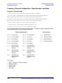
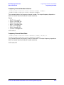
Frequency Channel Configuration - Band, Number, and State . . . . . . . . . . . . . . . . . . . . .4-36
Filter Configuration - Alpha, BbT, Optimization, Type . . . . . . . . . . . . . . . . . . . . . . . . . . . .4-38
FIX4 Data. . . . . . . . . . . . . . . . . . . . . . . . . . . . . . . . . . . . . . . . . . . . . . . . . . . . . . . . . . . . . . . .4-40
Frequency Correction (FCOR) Field . . . . . . . . . . . . . . . . . . . . . . . . . . . . . . . . . . . . . . . . . . .4-52
FSK Deviation . . . . . . . . . . . . . . . . . . . . . . . . . . . . . . . . . . . . . . . . . . . . . . . . . . . . . . . . . . . .4-52
Guard Field . . . . . . . . . . . . . . . . . . . . . . . . . . . . . . . . . . . . . . . . . . . . . . . . . . . . . . . . . . . . . .4-53
Idle Field . . . . . . . . . . . . . . . . . . . . . . . . . . . . . . . . . . . . . . . . . . . . . . . . . . . . . . . . . . . . . . . .4-53
I/Q Scaling . . . . . . . . . . . . . . . . . . . . . . . . . . . . . . . . . . . . . . . . . . . . . . . . . . . . . . . . . . . . . . .4-54
Leading Broadcast Bit (B1) Field . . . . . . . . . . . . . . . . . . . . . . . . . . . . . . . . . . . . . . . . . . . . .4-54
Mode State . . . . . . . . . . . . . . . . . . . . . . . . . . . . . . . . . . . . . . . . . . . . . . . . . . . . . . . . . . . . . . .4-55
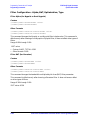
Modulation Configuration - Type, User FSK, User I/Q . . . . . . . . . . . . . . . . . . . . . . . . . . . .4-55
MSK Phase . . . . . . . . . . . . . . . . . . . . . . . . . . . . . . . . . . . . . . . . . . . . . . . . . . . . . . . . . . . . . . .4-60
P Field. . . . . . . . . . . . . . . . . . . . . . . . . . . . . . . . . . . . . . . . . . . . . . . . . . . . . . . . . . . . . . . . . . .4-60
Multiframe PN Sequence . . . . . . . . . . . . . . . . . . . . . . . . . . . . . . . . . . . . . . . . . . . . . . . . . . .4-62
Personal Station ID Code . . . . . . . . . . . . . . . . . . . . . . . . . . . . . . . . . . . . . . . . . . . . . . . . . . .4-64
Phase Polarity . . . . . . . . . . . . . . . . . . . . . . . . . . . . . . . . . . . . . . . . . . . . . . . . . . . . . . . . . . . .4-64
PN9 Mode . . . . . . . . . . . . . . . . . . . . . . . . . . . . . . . . . . . . . . . . . . . . . . . . . . . . . . . . . . . . . . . .4-65
Predefined Mode . . . . . . . . . . . . . . . . . . . . . . . . . . . . . . . . . . . . . . . . . . . . . . . . . . . . . . . . . .4-65
S Field. . . . . . . . . . . . . . . . . . . . . . . . . . . . . . . . . . . . . . . . . . . . . . . . . . . . . . . . . . . . . . . . . . .4-65
Scramble Configuration - Seed and State. . . . . . . . . . . . . . . . . . . . . . . . . . . . . . . . . . . . . . .4-67
Secondary Frame Configuration - Recall, Save, Trigger, State . . . . . . . . . . . . . . . . . . . . . .4-68
Slow Associated Control Channel (SACCH) Field . . . . . . . . . . . . . . . . . . . . . . . . . . . . . . . .4-69
Steal Bit . . . . . . . . . . . . . . . . . . . . . . . . . . . . . . . . . . . . . . . . . . . . . . . . . . . . . . . . . . . . . . . . .4-71
Symbol Rate . . . . . . . . . . . . . . . . . . . . . . . . . . . . . . . . . . . . . . . . . . . . . . . . . . . . . . . . . . . . . .4-71
Sync Output Configuration - Type, Timeslot, Offset . . . . . . . . . . . . . . . . . . . . . . . . . . . . . .4-71
Synchronization Block Bits (SSB) Field . . . . . . . . . . . . . . . . . . . . . . . . . . . . . . . . . . . . . . . .4-73
Synchronization Sequence Field . . . . . . . . . . . . . . . . . . . . . . . . . . . . . . . . . . . . . . . . . . . . . .4-73
Synchronization Training Sequence Bits (STS) Field . . . . . . . . . . . . . . . . . . . . . . . . . . . . .4-74
Synchronization Word Field . . . . . . . . . . . . . . . . . . . . . . . . . . . . . . . . . . . . . . . . . . . . . . . . .4-74
Tail (T1, T2) Fields. . . . . . . . . . . . . . . . . . . . . . . . . . . . . . . . . . . . . . . . . . . . . . . . . . . . . . . . .4-75
Timeslot Configuration - Amplitude, State, Type . . . . . . . . . . . . . . . . . . . . . . . . . . . . . . . .4-75
Trailing Broadcast Bit (B2) Field . . . . . . . . . . . . . . . . . . . . . . . . . . . . . . . . . . . . . . . . . . . . .4-82
Training Sequence Field . . . . . . . . . . . . . . . . . . . . . . . . . . . . . . . . . . . . . . . . . . . . . . . . . . . .4-82
Trigger Source . . . . . . . . . . . . . . . . . . . . . . . . . . . . . . . . . . . . . . . . . . . . . . . . . . . . . . . . . . . .4-86
xv
Contents
Unique Word Field . . . . . . . . . . . . . . . . . . . . . . . . . . . . . . . . . . . . . . . . . . . . . . . . . . . . . . . . 4-86
User FSK Files . . . . . . . . . . . . . . . . . . . . . . . . . . . . . . . . . . . . . . . . . . . . . . . . . . . . . . . . . . . 4-87
User I/Q Files . . . . . . . . . . . . . . . . . . . . . . . . . . . . . . . . . . . . . . . . . . . . . . . . . . . . . . . . . . . . 4-87
Programming Examples . . . . . . . . . . . . . . . . . . . . . . . . . . . . . . . . . . . . . . . . . . . . . . . . . . . . . . . 4-88
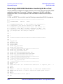
Generating a π/4 DQPSK Modulation Sensitivity Bit Error Test . . . . . . . . . . . . . . . . . . . 4-89
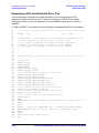
Generating a DECT GFSK Modulation Sensitivity Bit Error Test . . . . . . . . . . . . . . . . . . 4-96
Generating a GSM GMSK Modulation Sensitivity Bit Error Test. . . . . . . . . . . . . . . . . . . 4-98
Generating a PDC Sensitivity Bit Error Test . . . . . . . . . . . . . . . . . . . . . . . . . . . . . . . . . . 4-100
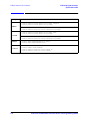
5. Softkey/Command Cross–Reference
. . . . . . . . . . . . . . . . . . . . . . . . . . . . . . . . . . . . . . . . . . . . . . . . . . . . . . . . . . . . . . . . . . . . . . . . . . . . 5-2
6. Theory of Operation
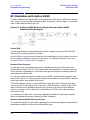
RF Modulation with Option UN8/9 . . . . . . . . . . . . . . . . . . . . . . . . . . . . . . . . . . . . . . . . . . . . . . . 6-2
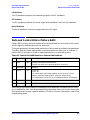
Data and Control Bits in Pattern RAM . . . . . . . . . . . . . . . . . . . . . . . . . . . . . . . . . . . . . . . . . . . . 6-3
Alternate Amplitude and Alternate Timeslot Amplitude Control (Option UNA only) . . . . . . . 6-4
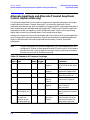
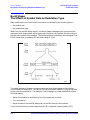
Burst Shape: The Effects of Symbol Rate & Modulation Type . . . . . . . . . . . . . . . . . . . . . . . . . . 6-6
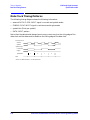
Data Clock Timing Patterns . . . . . . . . . . . . . . . . . . . . . . . . . . . . . . . . . . . . . . . . . . . . . . . . . . . . 6-8
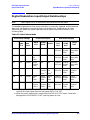
Digital Modulation Input/Output Relationships . . . . . . . . . . . . . . . . . . . . . . . . . . . . . . . . . . . . 6-9
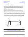
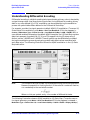
Understanding Differential Data Encoding. . . . . . . . . . . . . . . . . . . . . . . . . . . . . . . . . . . . . . . . 6-10
Understanding Differential Encoding . . . . . . . . . . . . . . . . . . . . . . . . . . . . . . . . . . . . . . . . . . . . 6-11
xvi
ESG Family Signal Generators
Options UN8 and 202
1 Overview of Modulation Formats
This manual describes the digital modulation capability provided by the Real-Time I/Q
Baseband Generator with TDMA formats (Option UN8 and includes Option 202).
Overviews are provided in this chapter, as well as the operating and programming
information and examples in the following chapters.
The modulation formats are described as follows:
• “APCO 25” on page 1-2
• “Bluetooth” on page 1-3
• “CDPD” on page 1-4
• “Custom” on page 1-5
• “DECT” on page 1-6
• “EDGE (Option 202 Only)” on page 1-7
• “GSM” on page 1-8
• “NADC” on page 1-9
• “PDC” on page 1-10
• “PHS” on page 1-11
• “TETRA” on page 1-12
Real-Time I/Q Baseband Generator User’s and Programming Guide
1-1
Overview of Modulation Formats
APCO 25
ESG Family Signal Generators
Options UN8 and 202
APCO 25
The Association of Public-Safety Communications Official-International, Inc., Project 25
(APCO 25) is a standard setting initiative for public-safety communications.
The primary objectives of the APCO Project 25 standards process are to provide digital
narrowband radios optimum performance, meet all public-safety user needs, and achieve
maximum interoperability.
The Project 25 documents were developed by the Telecommunications Industry
Association (TIA), based on user needs, and then approved by the APCO Project 25
Steering Committee before being published as TIA documents.
The basic characteristics of Project 25 radios are the following:
• a Phase I emission designator of 8K10F1E-compatible four-level frequency modulation
(C4FM) for operation in a 12.5 kHz channel
• a Phase II emission designator of 5K76G1E-compatible quadrature phase shift keying
(CQPSK) modulation for operation in a 6.25 kHz channel
NOTE
The only difference between Phase I C4FM and Phase II CQPSK is the
modulation method in the transmitter.
• use of a common receiver for both C4FM and CQPSK modulation to ensure full
interoperability between the two signals
• encryption defined for the U.S. Data Encryption Standard (DES) algorithms, but other
techniques can also be employed
• use of an improved multiband excitation (IMBE) vocoder with 4400 bits/s of digitized
voice, 3800 bits/s of error correction on the voice, and 2400 bits/s of signaling overhead,
for an aggregate bit rate of 9600 bits/s
1-2
Real-Time I/Q Baseband Generator User’s and Programming Guide
ESG Family Signal Generators
Options UN8 and 202
Overview of Modulation Formats
Bluetooth
Bluetooth
Bluetooth is a global specification for wireless communication. It provides limited range
RF connectivity for voice and data transmissions between electronic devices without the
use of cables.
Promoted by the Bluetooth Special Interest Group (SIG), Bluetooth operates in a globally
available unlicensed 2.4 GHz Industrial, Scientific, and Medical (ISM) radio band.
Although globally available, the exact location and the width of the band may differ by
country.
Bluetooth uses a Frequency Hopping Spread Spectrum (FHSS), and 2-level frequency shift
keying (2FSK) modulation that provides 1 bit of data per symbol with a symbol rate of
1 Ms/s. The frequency hopping occurs over 79 channels (23 channels in Spain, France and
Japan) spaced 1 MHz apart.
Bluetooth protocol uses a combination of circuit and packet switching. For full duplex
transmission, Time-Division Duplex (TDD) is used. Bluetooth uses slotted channels with a
nominal slot length of 625 µs. On the channel, information is exchanged through packets.
Each packet is transmitted on a different hop frequency. A packet nominally covers a
single slot, but can be extended to cover up to five slots. Slots can be reserved for
synchronous packets. Each voice channel supports a 64 kbits/s synchronous channel in
each direction. The synchronous channel can support a maximum of 721 kbits/s
asymmetric (and still up to 57.6 kbits/s in the return direction), or 432.6 kbits/s symmetric.
NOTE
Option UN8 does not implement the FHSS frequency hopping, so it is not
spread spectrum
.
Real-Time I/Q Baseband Generator User’s and Programming Guide
1-3
Overview of Modulation Formats
CDPD
ESG Family Signal Generators
Options UN8 and 202
CDPD
Cellular Digital Packet Data (CDPD) is a specification for supporting wireless
communications. CDPD is designed to work over Advanced Mobile Phone System (AMPS)
or as a protocol for Time Division Multiple Access (TDMA). CDPD is a transparent overlay
on an existing AMPS system. It makes use of AMPS channels that are not being utilized
by voice traffic.
CDPD enables you to send information in packets over the existing analog cellular
network. It is best suited for short periodic bursts of information. The packets of data are
sent over the existing infrastructure at a rate of up to 19.2 kbits/s.
1-4
Real-Time I/Q Baseband Generator User’s and Programming Guide
ESG Family Signal Generators
Options UN8 and 202
Overview of Modulation Formats
Custom
Custom
The Real-Time I/Q Baseband Generator enables you to shape the characteristics of a
digitally modulated signal. You can use it to create time-domain multiple access signals.
You can choose from a variety of modulation types, including QPSK, offset QPSK, BPSK,
π/4DQPSK, 4-, 16-, 32-, 64-, and 256-QAM, as well as define your own MSK, FSK, and I/Q
modulation types.
You can create and modify these custom modulation types using simple table editors, and
store custom files to the signal generator’s memory where they can be recalled on demand.
Using the table editors, you can adjust the signal’s data, frequency deviation, I value,
Q value, phase deviation, bit rate, filter alpha, FIR coefficient and value, and a channel
offset. Also, with user-defined IQ and FSK modulations, you can design custom differential
encoding schemes.
Real-Time I/Q Baseband Generator User’s and Programming Guide
1-5
Overview of Modulation Formats
DECT
ESG Family Signal Generators
Options UN8 and 202
DECT
The Digital European Cordless Telecommunications, (DECT) digital communications
standard defines an access technology for existing and future networks including PSTN,
ISDN and GSM for public applications and PBXs and X.25 for private networking.
Because DECT can be used to access any network, a wide range of cordless
communications systems are being developed using the DECT standard. The same
handset can be used in different applications allowing mobility between systems while
offering higher performance, both “in-building” and across wide geographic areas.
The DECT digital communications standard employs a 12:1 Time Division Multiple Access
(TDMA), Time Division Duplex (TDD). The raw bit rate, 1.152 Mbits/second, is modulated
using a system known as Gaussian Frequency Shift Keying (GFSK). This method deviates
the carrier frequency by +288 kHz to represent a logic 1 or −288 kHz to represent a logic 0.
The speech rate is 32 kbits/s and the raw data rate is 1.152 Mbits/s. The frequency
allocation is 1880 MHz to 1900 MHz. There are ten carriers in this band with a carrier
spacing of 1.728 MHz and a channel bandwidth of 1 MHz. The ten carriers are numbered 0
to 9 (where channel nine is the lowest frequency at 1881.792 MHz and channel zero is the
highest, at 1897.344 MHz).
Each of these carriers spaced across this 20 MHz band employ Time Division Multiple
Access, Time Division Duplex. This means that each carrier can be activated at any one of
the 24 available timeslots in a 10 ms timeframe. Duplex communication is achieved by
using the first 12 timeslots as the transmit time and the second 12 timeslots as the receive
time.
The power level in DECT is fixed at +24 dBm for both the fixed part and portable parts of
the system; it does not vary as in cellular systems.
The DECT framing structure is based on a hierarchical system consisting of timeslots,
TDMA frames, multiframes, and hyperframes. One traffic bearer burst (from mobile to
base station) consists of 390 modulated bits including of guard, preamble, synchronization,
signaling/data, and error correction bits. Twelve of these bursts make up one TDMA
frame. Eighteen TDMA frames make up one multiframe.
1-6
Real-Time I/Q Baseband Generator User’s and Programming Guide
ESG Family Signal Generators
Options UN8 and 202
Overview of Modulation Formats
EDGE (Option 202 Only)
EDGE (Option 202 Only)
The Enhanced Data Rates for GSM Evolution (EDGE) digital communications standard
defines a voice and data over-air interface between a mobile radio and the system
infrastructure. This standard was designed as the basis for a private radio
communications system. A central control center is linked to multiple base station sites
which provide the required coverage.
The EDGE digital communications standard employs a 8:1 Time Division Multiple Access
(TDMA) allowing eight channels to use one carrier frequency simultaneously. The
812.5 kbits/second raw bit rate is modulated with 3π/8 rotating 8PSK. This standard
defines the channel separation as 200 kHz at carrier frequencies between 935 and
960 MHz (downlink transmissions) and 890 to 915 MHz (uplink transmissions) at a power
level ranging between 3.7 mW and 20 W. The standard specifies a physical traffic channel
(TCH) with two logical components: a logical TCH and the slow associated control channel
(SACCH).
The EDGE framing structure is based on a hierarchical system consisting of timeslots,
TDMA frames, multiframes, and hyperframes. One traffic channel consists of either 468 or
471 modulated bits including tail, encryption, training sequence, and guard time bits.
Eight of these bursts make up one TDMA frame. Twenty-six TDMA frames make up one
multiframe. Frames 12 and 25 in the multiframe are dedicated to control channel
signaling (SACCH).
Guard time appears in the visual representation of the timeslot as a 24.75-bit field. In the
actual implementation, the guard time field in timeslots 0 and 4 are 27 bits long and the
remaining timeslots contain 24-bit fields.
Real-Time I/Q Baseband Generator User’s and Programming Guide
1-7
Overview of Modulation Formats
GSM
ESG Family Signal Generators
Options UN8 and 202
GSM
The Global System for Mobile Communication (GSM) digital communications standard
defines a voice and data over-air interface between a mobile radio and the system
infrastructure. This standard was designed as the basis for a private radio
communications system. A central control center is linked to multiple base station sites
which provide the required coverage.
The GSM digital communications standard employs a 8:1 Time Division Multiple Access
(TDMA) allowing eight channels to use one carrier frequency simultaneously. The
270.833 kbits/second raw bit rate is modulated using a system known as Gaussian
Minimum Shift Keying (GMSK). This standard defines the channel separation as 200 kHz
at carrier frequencies between 935 and 960 MHz (downlink transmissions) and 890 to
915 MHz (uplink transmissions) at a power level ranging between 3.7 mW and 20 W. The
standard includes multiple traffic channels, a control channel, and a cell broadcast
channel.
The GSM framing structure is based on a hierarchical system consisting of timeslots,
TDMA frames, multiframes, and hyperframes. One traffic channel consists of 156.25 (157)
modulated bits including tail, training sequence, encryption, and guard time, and timeslot
bits. Eight of these bursts make up one TDMA frame. Twenty-six TDMA frames make up
one multiframe. Frames 13 and 26 in the multiframe are dedicated to control channel
signaling.
Guard time appears in the visual representation of the timeslot as an 8.25-bit field. In the
actual implementation, the guard time field in timeslots 0 and 4 are 9 bits long and the
remaining timeslots contain 8 bit fields. (This implementation is documented in the GSM
standard “GSM REC. 05.10 Section 5.7” as follows: “Optionally, the BS may use a timeslot
length of 157 bit periods on timeslots with TN=0 and 4, and 156 bit periods on timeslots
with TN=1, 2, 3, 5, 6, 7, rather than 156.25 bit periods on all timeslots.”)
1-8
Real-Time I/Q Baseband Generator User’s and Programming Guide
ESG Family Signal Generators
Options UN8 and 202
Overview of Modulation Formats
NADC
NADC
The North American Digital Cellular digital communications standard defines a voice and
data over-air interface between a mobile radio and the system infrastructure. This
standard was designed as the basis for a private radio communications system. A central
control center is linked to multiple base station sites which provide the required coverage.
The NADC digital communications standard employs a 6:1 Time Division Multiple Access
(TDMA) allowing six channels to use one carrier frequency simultaneously. The raw bit
rate, 48.6 kbits/second, is modulated using a system known as π/4 Differential Quadrature
Phase Shift Keying (π/4DQPSK). This standard defines the channel separation as 30 kHz
at carrier frequencies between 824 and 849 MHz (uplink transmissions) and 869 to
894 MHz (downlink transmissions) at a power level ranging from 2.2 mW to 6W (mobile
station).
The NADC framing structure is based on a hierarchical system consisting of timeslots,
TDMA frames, multiframes, and hyperframes. One Normal Uplink Burst (from mobile to
base station) consists of 324 modulated bits consisting of guard, ramp, synchronization
word, slow associated control channel, color code, and data bits. Six of these bursts make
up one TDMA frame. Eighteen TDMA frames make up one multiframe. Frame 18 in the
multiframe is dedicated to control channel signaling.
Real-Time I/Q Baseband Generator User’s and Programming Guide
1-9
Overview of Modulation Formats
PDC
ESG Family Signal Generators
Options UN8 and 202
PDC
The Personal Digital Cellular (PDC) digital communications standard defines a voice and
data over-air interface between a mobile radio and the system infrastructure. A central
control center is linked to multiple base station sites which provide the required coverage.
The PDC digital communications standard employs a 6:1 Time Division Multiple Access
(TDMA) allowing six channels to use one carrier frequency simultaneously. The raw bit
rate, 42 kbits/second, is modulated using a system known as π/4 Differential Quadrature
Phase Shift Keying (π/4DQPSK). This standard defines the channel separation as 50 kHz
(25 kHz interleave) in two separate frequency bands: 810 to 826 MHz (downlink
transmission) 940 to 956 MHz (uplink transmission), as well as 1477 to 1501 MHz
(downlink transmission) 1429 to 1453 MHz (uplink transmission) at a power level of 0.8 W
(mobile station). The standard includes a control channel, multiple traffic channels, and
other logical channel types.
The PDC framing structure is based on a hierarchical system consisting of timeslots,
TDMA frames, multiframes, and hyperframes. One uplink traffic channel burst (from
mobile to base station) consists of 280 modulated bits including ramp, data, preamble,
synchronization word, color code, steal flag, slow associated access channel, and guard bits.
Six of these bursts make up one TDMA frame. Eighteen TDMA frames make up one
multiframe.
1-10
Real-Time I/Q Baseband Generator User’s and Programming Guide
ESG Family Signal Generators
Options UN8 and 202
Overview of Modulation Formats
PHS
PHS
The Personal Handy Phone System (PHS) digital communications standard defines a voice
and data over-air interface between a mobile radio and a base station/network interface. A
central control center is linked to multiple base station sites which provide the required
coverage.
The PHS digital communications standard employs a 4:1 Time Division Multiple Access
(TDMA), Time Division Duplex (TDD), allowing eight channels to use one carrier
frequency simultaneously. The 384 kbits/second raw bit rate is modulated using a system
known as π/4 Differential Quadrature Phase Shift Keying (π/4DQPSK). This standard
defines the channel separation as 300 kHz at carrier frequencies between 1895 and
1918 MHz at a power level of 10 mW (mobile station). The standard includes a multiple
uplink and downlink traffic channels and a dedicated control (synchronization) channel.
The PHS framing structure is based on a hierarchical system consisting of timeslots,
TDMA frames, multiframes, and hyperframes. One transmission burst consists of 240
modulated bits including ramp, start symbol, preamble, unique word, channel identifier,
slow associated control channel, traffic channel data, cycle redundancy check, and guard
bits. Eight of these bursts make up one TDMA frame. Eighteen TDMA frames make up
one multiframe.
Real-Time I/Q Baseband Generator User’s and Programming Guide
1-11
Overview of Modulation Formats
TETRA
ESG Family Signal Generators
Options UN8 and 202
TETRA
The Trans European Trunked Radio or TETRA digital communications standard defines a
voice and data over-air interface between a mobile radio and the system infrastructure.
This standard was designed as the basis for a private radio communications system. A
central control center is linked to multiple base station sites which provide the required
coverage.
The TETRA digital communications standard employs a 4:1 Time Division Multiple Access
(TDMA) allowing four channels to use one carrier frequency simultaneously. The raw bit
rate, 36k bits/second, is modulated using a system known as π/4 Differential Quadrature
Phase Shift Keying (π/4DQPSK). This standard defines the channel separation as 25 kHz
at carrier frequencies surrounding 400 MHz. The standard includes a Broadcast Control
Channel, multiple Traffic Channels, and a host of other logical channel types.
The TETRA framing structure is based on a hierarchical system consisting of
timeslots/bursts, TDMA frames, multiframes, and hyperframes. One Normal Uplink Burst
(from mobile to base station) consists of 510 modulated bits consisting of ramp, tail,
training, data, and guard bits. Four of these bursts make up one TDMA frame. Eighteen
TDMA frames make up one multiframe. Frame 18 in the multiframe is dedicated to
control channel signaling.
1-12
Real-Time I/Q Baseband Generator User’s and Programming Guide
HP ESG Family Signal Generators
Options UN8 and 202
2 Using Functions
This chapter contains procedures that show you how to use some of the major functions of
real-time I/Q baseband signal generation (Option UN8 and the EDGE format Option 202):
• “Setting Up Framed Digital Modulation” on page 2-2
• “Using Custom Format” on page 2-5
• “Turning On a Format and the Modulation” on page 2-6
• “Customizing the Burst Shape” on page 2-7
• “Mapping Custom Differential Encoding” on page 2-11
• “Mapping Symbol Positions with the I/Q Table Editor” on page 2-15
• “Building a Customized FSK Modulation with the FSK Table Editor” on page 2-22
• “Creating User-Defined FIR Filters” on page 2-26
• “Storing User-Defined Files to Memory” on page 2-33
• “Selecting Stored Files” on page 2-35
• “Using the Bit File Editor” on page 2-38
The material in this chapter is presented with the assumption that you are familiar with
basic instrument operation, such as setting power level and frequency, and using a table
editor. If you are not, refer to the quick start guide before using the procedures in this
chapter.
NOTE
When you see desired format in a menu path, it means to choose the
appropriate softkey for the communication standard that you are working in:
•
•
•
•
Custom
DECT
EDGE (Option 202)
GSM
•
•
•
•
NADC
PDC
PHS
TETRA
Real-Time I/Q Baseband Generator User’s and Programming Guide
2-1
Using Functions
Setting Up Framed Digital Modulation
HP ESG Family Signal Generators
Options UN8 and 202
Setting Up Framed Digital Modulation
Use the following procedure to configure the signal generator to output a framed
digitally-modulated signal. The basic steps to the procedure are to:
• Set the carrier frequency (see below)
• Set the power level (see below)
• Select the desired format (page 2-3)
• Choose a timeslot and select a data pattern for it (page 2-3)
• Choose a second timeslot and select a data pattern for it (page 2-4)
• Turn on the modulation (page 2-6)
Setting the Carrier Frequency
1. Preset the signal generator to normal preset conditions.
2. Set the frequency to:
• Custom:
1.894880 GHz
• NADC: 835 MHz
• DECT:
1.890000 GH
• PDC: 832 MHz
• EDGE: 891 MHz
• PHS:
• GSM:
• TETRA: 1.894880 GHz
891 MHz
1.89515 GHz
Setting the Power Level
Set the power level (in dBm) to:
• Custom:
0
• NADC:
0
• DECT:
−10
• PDC:
0
• EDGE:
−5
• PHS:
0
• GSM:
−5
• TETRA: 0
2-2
Real-Time I/Q Baseband Generator User’s and Programming Guide
HP ESG Family Signal Generators
Options UN8 and 202
Using Functions
Setting Up Framed Digital Modulation
Selecting the Desired Format
Press the front panel Mode key and press TDMA > Real Time I/Q BaseBand (if it appears) >
desired format to select the communication standard that you want.
Setting Up the First Timeslot
1. Toggle the Data Format Pattern Framed softkey to Framed.
When you choose framed data, the timeslots that you activate are bursted, and there is
no RF carrier during the off timeslots.
2. Press the softkey Configure Timeslots.
3. Set the following conditions:
Format
Timeslot #
Timeslot Type
DECT
Data Pattern1
Timeslot On/Off
8 1’s & 8 0’s
0
Custom
NADC
1
Uplink Control 1 (Up TCH)
PDC
0
Downlink Traffic Channel (Down TCH)
PHS
Downlink 1
TETRA
1
EDGE
& GSM
1Softkey
On
FIX4, 0101
Custom
Uplink Control 1 (Up Control 1)
Locations
DECT:
Configure Custom > Other Patterns > 8 1’s & 8 0’s
All others: Configure timeslot type > Data > FIX4, then enter 0101
Real-Time I/Q Baseband Generator User’s and Programming Guide
2-3
Using Functions
Setting Up Framed Digital Modulation
HP ESG Family Signal Generators
Options UN8 and 202
Setting Up the Second Timeslot
Return to the Configure Timeslots menu and set the following conditions:
Format
Timeslot #
DECT
11
Traffic Bearer
EDGE
7
Normal
GSM
7
Normal
NADC
3
Uplink Traffic Channel (Up TCH)
PDC
2
Downlink Traffic Channel (Down TCH)
PHS
Uplink 1
TETRA
3
1Softkey
2-4
Timeslot Type
Data Pattern1
Timeslot On/Off
4 1’s & 4 0’s
On
Custom
Uplink Custom (Up Custom)
Locations:
DECT:
Configure Traffic Bearer > Other Patterns > B field > 4 1’s & 4 0’s
EDGE:
Configure Normal > E > 4 1’s & 4 0’s
GSM:
Configure Normal > E > 4 1’s & 4 0’s
NADC:
Configure Up TCH > Data > Other Patterns > 4 1’s & 4 0’s
PDC:
Configure Down TCH > TCH > Other Patterns > 4 1’s & 4 0’s
PHS:
Configure Custom > Other Patterns > 4 1’s & 4 0’s
TETRA:
Configure Up Custom > Other Patterns > 4 1’s & 4 0’s
Real-Time I/Q Baseband Generator User’s and Programming Guide
HP ESG Family Signal Generators
Options UN8 and 202
Using Functions
Using Custom Format
Using Custom Format
The Custom format enables you to create a unique, unframed digital modulation. The
following figure shows the Custom menu (Mode > Real Time I/Q BaseBand (if it appears) >
Custom), and the default values for this format.
Using the softkeys in this menu, you can edit any of the default values.
Procedures are provided in this chapter for specific types of editing:
• “Customizing the Burst Shape” on page 2-7
• “Mapping Custom Differential Encoding” on page 2-11
• “Mapping Symbol Positions with the I/Q Table Editor” on page 2-15
• “Building a Customized FSK Modulation with the FSK Table Editor” on page 2-22
• “Creating a User-Defined FIR Filter by Entering Values” on page 2-26
• “Storing User-Defined Files to Memory” on page 2-33
• “Selecting Stored Files” on page 2-35
Real-Time I/Q Baseband Generator User’s and Programming Guide
2-5
Using Functions
Turning On a Format and the Modulation
HP ESG Family Signal Generators
Options UN8 and 202
Turning On a Format and the Modulation
Once you have the modulation set up as you want, use the following steps to apply it to a
carrier.
1. Go to the first desired format menu and toggle the modulation format on.
Annunciators turn on to indicate:
• that you have enabled the standard
• that I/Q modulation is being generated
2. Set the desired frequency.
3. Set the desired power.
4. When the instrument is preset, modulation is On by default. If the MOD ON annunciator
is not enabled, press the front panel Mod On/Off hardkey to display the annunciator and
apply the custom modulation to the carrier.
5. Turn on the RF output.
2-6
Real-Time I/Q Baseband Generator User’s and Programming Guide
HP ESG Family Signal Generators
Options UN8 and 202
Using Functions
Customizing the Burst Shape
Customizing the Burst Shape
The default burst shape of each format is implemented according to the standards of the
format selected. You can, however, modify the following aspects of the burst shape:
• Rise time - the period of time, specified in bits, where the burst increases from a
minimum of −70 dB (0) to full power (1).
• Fall time - the period of time, specified in bits, where the burst decreases from full
power (1) to a minimum of −70 dB (0).
• Rise delay - the period of time, specified in bits, that the start of the burst rise is
delayed. Rise delay can be either negative or positive. Entering a delay other than zero
shifts the full power point earlier or later than the beginning of the first useful symbol.
• Fall delay - the period of time, specified in bits, that the start of the burst fall is delayed.
Fall delay can be either negative or positive. Entering a delay other than zero shifts the
full power point earlier or later than the end of the last useful symbol.
• User-defined burst shape - up to 256 user-entered values which define the shape of the
curve in the specified rise or fall time. The values can vary between 0 (no power) and
1 (full power) and are scaled linearly. Once specified, the values are resampled as
necessary to create the cubic spline that passes through all of the sample points.
User-Defined
Values
User-Defined
Values
Power
1
0
Rise
Delay
Rise
Time
Fall
Delay
Fall
Time
Time
Try the following procedures which demonstrate customizing the burst shape.
NOTE
For further information on burst shape, see “Burst Shape:
The Effects of Symbol Rate & Modulation Type” on page 6-6.
Real-Time I/Q Baseband Generator User’s and Programming Guide
2-7
Using Functions
Customizing the Burst Shape
HP ESG Family Signal Generators
Options UN8 and 202
Changing Rise and Fall Times and Adding Delay
1. Press the front panel Mode hardkey.
2. In the softkey menu, press Real Time I/Q BaseBand (if it appears) > Custom > Burst Shape
Other Formats: Real Time I/Q BaseBand (if it appears) > TDMA > desired format >
More (1 of 2) > Modify Standard > Burst Shape
The softkeys for adjusting the rise and fall times and delays are displayed. The
following figure shows this menu in the Custom format.
3. Now you can change the rise and fall times and delays by pressing the proper softkey
and entering a new value.
NOTE
2-8
To return the burst to the default conditions, press the
Restore Default Burst Shape softkey.
Real-Time I/Q Baseband Generator User’s and Programming Guide
HP ESG Family Signal Generators
Options UN8 and 202
Using Functions
Customizing the Burst Shape
Defining the Shape of the Burst Curve
You can adjust the shape of the rise time curve and the fall time curve using the rise shape
and fall shape editors. Each editor allows you to enter up to 256 values, equidistant in
time, to define the shape of the curve. The values are then resampled to create the cubic
spline that passes through all of the sample points.
1. To access the editors, press Define User Burst Shape. The editors are shown in the
following figure. Notice that the cursor is active in the Rise Shape Editor.
2. Enter values in the Rise Shape Editor to match those shown in the following figure.
3. Press Edit Fall Shape to activate the cursor in the Fall Shape Editor.
4. Press Load Mirror Image of Rise Shape and the confirm softkey to change the fall shape
values to a mirror image of the rise shape values.
Real-Time I/Q Baseband Generator User’s and Programming Guide
2-9
Using Functions
Customizing the Burst Shape
HP ESG Family Signal Generators
Options UN8 and 202
5. Press Display Burst Shape to view a graphical representation of the waveform’s rise and
fall characteristics, as shown.
6. To use the new burst shape, first store the file, then load it. For help in executing these
store and load functions, refer to “Storing User-Defined Files to Memory” on page 2-33
and to “Selecting Stored Files” on page 2-35.
NOTE
2-10
You can also design burst shape files externally and download the data to the
signal generator. For more information see “Burst Shape Files, Creating”
on page 4-10.
Real-Time I/Q Baseband Generator User’s and Programming Guide
HP ESG Family Signal Generators
Options UN8 and 202
Using Functions
Mapping Custom Differential Encoding
Mapping Custom Differential Encoding
Differential encoding is a digital-encoding technique that denotes a binary value by a
signal change rather than a particular signal state. The signal generator has an editor that
enables you to manipulate the differential state map associated with user-defined I/Q and
user-defined FSK modulations. Using differential encoding, you can encode binary data
encoded during the modulation process via transitions between states defined in the
symbol table. Once you configure the differential encoding, you can activate and apply it to
the current user-defined modulation.
NOTE
For more details, see “Understanding Differential Encoding” on page 6-11.
Creating a User-Defined I/Q Modulation
Before you design a custom differential encoding scheme, you must first create a
user-defined I/Q or FSK modulation. For the purposes of this example, you will create a
user-defined 4QAM I/Q modulation from the signal generator’s list of default I/Q maps.
1. Press Mode > Real Time I/Q Base Band (if it appears) > Custom > Modulation Type >
Define User I/Q > More (1 of 2) > Load Default I/Q Map > QAM > 4QAM
Other Formats: Mode > Real Time I/Q Base Band (if it appears) > TDMA > desired format >
More (1 of 2) > Modify Standard > Modulation Type > Define User I/Q > More (1 of 2) >
Load Default I/Q Map > QAM > 4QAM
This loads a default 4QAM I/Q modulation and displays it in the I/Q table editor.
The default 4QAM I/Q modulation contains data that represent 4 symbols (00, 01, 10,
and 11) mapped into the I/Q plane using 2 distinct values (1.000000 and −1.000000).
These 4 symbols will be traversed during the modulation process by the symbol table
offset values associated with each symbol of data.
Real-Time I/Q Baseband Generator User’s and Programming Guide
2-11
Using Functions
Mapping Custom Differential Encoding
HP ESG Family Signal Generators
Options UN8 and 202
2. Press Configure Differential Encoding. This opens the differential state map editor. You
are now prepared to create a custom differential encoding for the user-defined default
4QAM I/Q modulation.
Editing the Differential State Map
The editor functions in the same manner as the I/Q and FSK table editors (explained in
“Mapping Symbol Positions with the I/Q Table Editor” on page 2 -15 and “Building a
Customized FSK Modulation with the FSK Table Editor” on page 2 -22).
The following illustration shows the differential state map editor, along with the location
of the data listing and the symbol table offset values entry area.
Data
Symbol table offset values entry area
1. To encode the first symbol, add a symbol table offset of 1 by pressing 1 > Enter. This will
rotate forward through the state map by 1 value when a data value of 0 is modulated.
Cursor prepared for next entry
2-12
UNSTORED condition
Real-Time I/Q Baseband Generator User’s and Programming Guide
HP ESG Family Signal Generators
Options UN8 and 202
NOTE
Using Functions
Mapping Custom Differential Encoding
Notice that (UNSTORED) appears next to Differential State Map on the
signal generator’s display. Differential state maps are associated with the
user-defined modulation for which they were created. In order to save a
custom differential state map, you must store the user-defined modulation for
which it was designed. Otherwise the symbol table offset data will be purged
when you press the Confirm Exit From Table Without Saving softkey when
exiting from the I/Q or FSK table editor.
2. To encode the second symbol, add a symbol table offset of −1 by pressing +/- > 1 > Enter.
This will rotate backward through the state map by 1 value when a data value of 1 is
modulated.
NOTE
At this point, the modulation has one bit per symbol. For the first two data
values (00000000 and 00000001) only the last bits (the 0 and the 1,
respectively) are significant.
3. To encode the third symbol, add a symbol table offset of 2 by pressing 2 > Enter. This
will rotate forward through the state map by 2 values when a data value of 10 is
modulated.
4. To encode the fourth symbol, add a symbol table offset of 0 by pressing 0 > Enter. This
will not rotate through the state map when a data value of 11 is modulated.
NOTE
At this point, the modulation has two bits per symbol. For the data values
00000000, 00000001, 00000010, 00000011, the symbol values are 00, 01, 10,
and 11 respectively.
5. Press Return to go back to the I/Q table editor.
Real-Time I/Q Baseband Generator User’s and Programming Guide
2-13
Using Functions
Mapping Custom Differential Encoding
HP ESG Family Signal Generators
Options UN8 and 202
Applying the Custom Differential Encoding
To apply a custom differential encoding to a user-defined modulation, press
Differential Encoding Off On until On is highlighted. The user-defined modulation will now
be differentially encoded.
2-14
Real-Time I/Q Baseband Generator User’s and Programming Guide
HP ESG Family Signal Generators
Options UN8 and 202
Using Functions
Mapping Symbol Positions with the I/Q Table Editor
Mapping Symbol Positions with the I/Q Table Editor
In modulation schemes defined by standards (such as TDMA and CDMA), symbols appear
in default positions in the I/Q plane. The I/Q table editor provided in Option UN8 enables
you to do the following:
• Create a unique mapping of symbols.
You can create a mapping that is not supplied as a default. You can also create a
non-standard mapping; this is often necessary for a proprietary modulation scheme.
• Change the position of one or more symbols in a standard mapping.
This is often done to test the sensitivity of a receiver, or to create a symbol mapping that
is similar to a default.
The examples in this section provide information on how to create an I/Q map (on
page 2-16), how to edit a default map (on page 2-19), how to globally change a value in an
I/Q table (on page 2-21), and how to use a stored I/Q map (on page 2-35).
Four data bits define each symbol.
Unique I and/or Q levels
A map in I or Q is limited to 16 unique levels.
You can generate up to 256 unique states.
Define User I/Q
softkey menu
Active entry area
I and Q values
Levels do not have to be symmetric.
Maximum of 16 unique levels
Real-Time I/Q Baseband Generator User’s and Programming Guide
2-15
Using Functions
Mapping Symbol Positions with the I/Q Table Editor
HP ESG Family Signal Generators
Options UN8 and 202
Creating a Symbol Map
Use the following procedure to create and store a 4-symbol unbalanced QPSK.
Accessing the I/Q Table Editor
1. Preset the signal generator.
2. Press the front panel Mode key.
3. In the softkey menu, press Real Time I/Q BaseBand (if this softkey does not appear, go to
step 4).
4. Display the I/Q table editor by pressing: Custom > Modulation Type > Define User I/Q
Other Formats: TDMA > desired format > More (1 of 2) > Modify Standard >
Modulation Type > Define User I/Q
The following illustration shows the I/Q table editor with data for a 4QAM I/Q map.
Clearing Data
When you create a new I/Q map (rather than editing existing data), it is often easier to
start with an empty table. Use the following steps to clear existing data from the table
editor.
1. Press More (1 of 2) to view the second page of softkeys.
2. Press Delete All Rows > Confirm Delete of All Rows. All data is removed from the table.
3. Press More (2 of 2) to return to the first page of softkeys.
4. Press Display I/Q Map. The data list is replaced by a blank I/Q state map.
5. To redisplay the list, press Return. As you enter data, you can toggle between the list
and the map to visually check the entries.
2-16
Real-Time I/Q Baseband Generator User’s and Programming Guide
HP ESG Family Signal Generators
Options UN8 and 202
Using Functions
Mapping Symbol Positions with the I/Q Table Editor
Entering I and Q Values
Next you will enter the coordinates of each symbol. The position of a symbol is defined by a
pair of values (one representing I and the other representing Q).
Symbol
Data Bits
I Value
Q Value
0
0000
0.500000
1.000000
1
0001
−0.500000
1.000000
2
0010
0.500000
−1.000000
3
0011
−0.500000
−1.000000
Both the 4QAM I/Q map shown on page 2-16, and the map you create in this example have
four symbols. Please note, however, that the 4QAM I/Q map uses only two unique values
(−1.0 and 1.0) to create those symbols, while this example uses the following four unique
values: 0.5, 1.0, −0.5, and −1.0. It is not the number of values that defines how many
symbols a map has, but how those values are combined.
NOTE
The number of bits per symbol can be expressed using the following formula.
Because the equation is a ceiling function, if the value of x contains a fraction,
x is rounded up to the next whole number.
Where x = bits per symbol, and y = the number of I/Q states.
The following figure summarizes the process of entering values in the I/Q table editor.
Detailed steps begin on the next page.
1. Use the arrow keys to highlight
where you wish to enter a value.
2. Use the keypad to enter the desired value.
3. Press Enter to accept the value.
Because there
are no values in
an empty table,
this list is empty.
Real-Time I/Q Baseband Generator User’s and Programming Guide
2-17
Using Functions
Mapping Symbol Positions with the I/Q Table Editor
HP ESG Family Signal Generators
Options UN8 and 202
1. Note that the entry under I Value is highlighted. Use the numeric keypad to type the
first I value from the table on page 2-17. You do not have to type the leading zero, or the
zeros that follow the number 5.
As you press the keys, the numbers display in the active entry area (if you make a
mistake, use the backspace key and then retype).
2. To accept the value, press the Enter softkey. Note that the I value updates, the highlight
moves to the first Q entry (and provides a default value of 0), and an empty row of data
appears below the first row.
Also note that 0.000000 appears as the first entry in the list of Distinct Values, and
that 0.500000 appears as the second entry.
NOTE
The maximum number of distinct (unique) values that can appear in any
I/Q map is 16. This is not the maximum number of I/Q entries; this is simply
the maximum number of distinct values that you can use to create the
entries. For example, if you load the default 256QAM map, you will see that
16 distinct values have been used to create far more than 16 I/Q entries.
3. For the first Q Value, type 1, then press Enter. The Q value
updates, and the highlight moves to the second I value. Now
0.500000 and 1.000000 are listed as the distinct values.
4. Enter the remaining I and Q values. Remember that you can
view the I/Q map at any time (using the Display I/Q Map
softkey, as described in “Clearing Data” on page 2 -16). The
figure to the right shows a completed constellation.
Storing the I/Q Map to Memory
Now that you have created a customized I/Q map, you can save it for future use. See
“Storing User-Defined Files to Memory” on page 2-33.
2-18
Real-Time I/Q Baseband Generator User’s and Programming Guide
HP ESG Family Signal Generators
Options UN8 and 202
Using Functions
Mapping Symbol Positions with the I/Q Table Editor
Moving an I/Q Symbol
You can manipulate symbol locations to simulate magnitude and phase errors. In this
example, you will edit a 4QAM constellation to move one symbol closer to the origin.
Loading the 4QAM I/Q Map
1. Preset the signal generator, then press the front panel Mode key.
2. In the softkey menu, press Real Time I/Q BaseBand (if it appears) > Custom >
Modulation Type > Define User I/Q > More (1 of 2) > Load Default I/Q Map > QAM > 4QAM
Other Formats: Real Time I/Q BaseBand (if it appears) > TDMA > desired format >
More (1 of 2) > Modify Standard > Modulation Type > Define User I/Q > More (1 of 2) >
Load Default I/Q Map > QAM > 4QAM
The I/Q table editor displays the data for the 4QAM I/Q map.
3. Press More (2 of 2) to return to the first page of softkeys.
The following illustration of the I/Q table editor shows the data for a 4QAM I/Q map.
4. Remember that you can view the I/Q map at any time (using
the Display I/Q Map softkey, as described in “Clearing Data”
on page 2 -16). The figure to the right shows a 4QAM I/Q
constellation.
Real-Time I/Q Baseband Generator User’s and Programming Guide
2-19
Using Functions
Mapping Symbol Positions with the I/Q Table Editor
HP ESG Family Signal Generators
Options UN8 and 202
Editing I and Q Values
The following figure summarizes the process of editing values in the I/Q table editor.
Detailed steps begin after the figure.
1. Use the arrow keys to highlight
the value you wish to edit.
2. Use the keypad to enter the desired value.
3. Press Enter to accept the new value.
1. Note that the first I value is highlighted. Using the numeric keypad, type 0.235702.
As you press the keys, the numbers display in the active entry area (if you make a
mistake, use the backspace key and then retype).
2. To accept the value, press the Enter softkey. Note that the I value updates, and the
highlight moves to the first Q entry.
3. For the first Q entry, enter 0.235702 and press Enter.
4. In the softkey menu, press Display I/Q Map. Note that one symbol has moved, as shown
in the following figure.
Storing the modified I/Q Map to Memory
Now that you have modified the I/Q map, you can save it for future use. See “Storing
User-Defined Files to Memory” on page 2-33.
2-20
Real-Time I/Q Baseband Generator User’s and Programming Guide
HP ESG Family Signal Generators
Options UN8 and 202
Using Functions
Mapping Symbol Positions with the I/Q Table Editor
Globally Replacing an I/Q Value
When you want to change an I/Q value throughout the entire table, you can change the
value once and have all occurrences of that value change to the new value. In this example,
you will use the Globally Replace Selected Item command to globally replace I/Q values.
NOTE
When using the Globally Replace Selected Item command, be sure that you
want all occurrences of the selected value changed. Also, consider the order in
which you change values. For example, if you want to change all current 0.5
values to 1.0, and all current 1.0 values to –0.75, change the 1.0 values first,
or all values will end up as –0.75.
1. Load a 4QAM I/Q map into the table editor as described on page 2-19.
2. Select any occurrence of the value 1.000000, then select the softkey
Globally Replace Selected Item.
3. Using the numeric keypad, type 0.5, then press the Enter softkey.
Note that all entries in the table that were originally 1.000000 now read 0.500000.
4. Select any occurrence of the value -1.000000, then press the softkey
Globally Replace Selected Item.
5. Using the numeric keypad, type -0.5, then press the Enter softkey.
Note that all entries in the table that were originally -1.000000 now read -0.500000.
6. In the softkey menu, press Display I/Q Map. Note that you have moved all of the symbols,
as shown below.
Storing the I/Q Map to Memory
As described in “Storing User-Defined Files to Memory” on page 2-33, you can save this
modified map for future use (Load/Store > Store To File).
Real-Time I/Q Baseband Generator User’s and Programming Guide
2-21
Using Functions
Building a Customized FSK Modulation with the FSK Table Editor
HP ESG Family Signal Generators
Options UN8 and 202
Building a Customized FSK Modulation with the
FSK Table Editor
Use this procedure to create, store, and apply a customized, continuous 4-level FSK signal.
You will learn to do the following:
• Choose the Define User FSK setting
• Create a unique file of frequency deviations
• Load and modify a default FSK pattern
Choosing the Define User FSK Setting
1. Preset the signal generator to normal preset conditions.
2. Press the front panel Mode hardkey. (If you have multiple options installed in your
signal generator, press the Real Time I/Q BaseBand softkey to select Option UN8.)
3. Choose the desired modulation and select the Define User FSK menu:
Custom: Custom > Modulation Type > Define User FSK
Other Formats: TDMA > desired format > More (1 of 2) > Modify Standard >
Modulation Type > Define User FSK
4. You will see a Frequency Values table with Data in the first column and Freq.
Deviation in the second column. The following illustration of the FSK table editor
shows the data for an 8-level FSK modulation.
Active entry area
2-22
Frequency values
Define User FSK softkey menu
Real-Time I/Q Baseband Generator User’s and Programming Guide
HP ESG Family Signal Generators
Options UN8 and 202
Using Functions
Building a Customized FSK Modulation with the FSK Table Editor
Creating a Unique FSK File of Frequency Deviations
There are two ways to create a custom FSK file. You can either define the frequency
deviations using completely original data (see "Using Original Data" below), or you can
load and modify a default FSK pattern (see “Modifying a Default FSK Pattern”
on page 2-24).
Using Original Data
Use the following instructions to create an example of an APCO25 C4FM customized
continuous 4-level FSK signal with two bits per symbol.
NOTE
The number of bits per symbol can be expressed using the following formula.
Because the equation is a ceiling function, if the value of x contains a fraction,
x is rounded up to the next whole number.
Where x = bits per symbol, and y = the number of frequencies.
When you create new frequency values (rather than edit existing data), it is often easier to
start with an empty table. To clear the existing frequency values from within the Define
User FSK menu, press More (1 of 2) > Delete All Rows > Confirm Delete Of All Rows.
The following figure defines the areas of the display. As you enter frequency deviation
values, the numbers will display in the active entry area (if you make a mistake, use the
backspace key and then retype). Follow the steps below:
1. For the first frequency deviation value, enter 600 Hz. Note that each time you enter a
value, the Data column increments to the next binary number, up to a total of 16 data
values (from binary 0000 to binary 1111).
Unstored custom frequency values
Frequency deviation active entry area
Real-Time I/Q Baseband Generator User’s and Programming Guide
Frequency terminator softkeys
2-23
Using Functions
Building a Customized FSK Modulation with the FSK Table Editor
HP ESG Family Signal Generators
Options UN8 and 202
2. Enter the remaining frequency deviation values:
• Data row 0001: +1.8 kHz
• Data row 0010: -600 Hz
• Data row 0011: -1.8 kHz
Storing the Custom FSK Modulation to a File
You have created an unstored file of frequency deviation values for a custom 4-level FSK
file. To learn how to store the file, see “Storing User-Defined Files to Memory”
on page 2-33.
Modifying a Default FSK Pattern
The basic steps in adding errors to a default modulation:
• Load the default synchronous FSK modulation.
• Designate a frequency deviation value.
• Choose an FSK pattern.
1. From the Define User FSK softkey menu, press More (1 of 2) > Load Default FSK.
2. Enter 1.8 kHz as the frequency deviation.
You will see 1.8000 kHz displayed in the Freq: active entry area of the display, and in
bold under the Freq Dev softkey. See the following figure.
Active entry area
2-24
Load Default FSK softkey menu
Real-Time I/Q Baseband Generator User’s and Programming Guide
HP ESG Family Signal Generators
Options UN8 and 202
Using Functions
Building a Customized FSK Modulation with the FSK Table Editor
3. Press the 4-Lvl FSK softkey. You will see the FSK table editor with the default
Frequency Values displayed. See the following figure.
Default frequency values
4. Highlight the frequency value for data row 0000, then modify the first frequency
deviation value as follows:
• Press More (2 of 2) > Edit Item.
• Change the value to -1.810 kHz.
• Notice that the highlight bar moves to data row 0001.
5. Enter the following frequency deviation values:
• Data row 0001: -590 Hz
• Data row 0010: +1.805 kHz
• Data row 0011: +610 Hz
You have created an unstored file of frequency deviation values for your custom 4-level
FSK file. To learn how to store the file, see “Storing User-Defined Files to Memory”
on page 2-33.
Storing the Custom FSK Modulation to a File
Now that you have created a customized FSK modulation that you can save for future use.
See “Storing User-Defined Files to Memory” on page 2-33.
Real-Time I/Q Baseband Generator User’s and Programming Guide
2-25
Using Functions
Creating User-Defined FIR Filters
HP ESG Family Signal Generators
Options UN8 and 202
Creating User-Defined FIR Filters
You can use the FIR table editor to create a customized FIR filter either by entering
coefficient values, or by modifying the values of an existing filter (see page 2-30).
Creating a User-Defined FIR Filter by Entering Values
Use this procedure to create and store an 8-symbol, windowed sinc function filter with an
oversample ratio of 4.
Accessing the Table Editor
1. Preset the signal generator, then press the front panel Mode key.
2. In the softkey menu, press Real Time I/Q BaseBand (if it appears) > Custom > Filter >
Define User FIR
Other Formats: Real Time I/Q BaseBand (if it appears) > TDMA > desired format >
More (1 of 2) > Modify Standard > Filter > Define User FIR
The FIR table editor is displayed, as shown in the following illustration.
Entering the Coefficient Values
The FIR table editor creates a filter from values that you provide.
NOTE
In this example, the values you enter are listed after step 3.
1. When you create new coefficient values (rather than edit existing data), it is often
easier to start with an empty table. If there are existing coefficient values in the table
editor, press More (1 of 2) > Delete all Rows > Confirm Delete Of All Rows to clear the table.
2-26
Real-Time I/Q Baseband Generator User’s and Programming Guide
HP ESG Family Signal Generators
Options UN8 and 202
Using Functions
Creating User-Defined FIR Filters
2. Note that the coefficient 0 Value field is highlighted. Use the numeric keypad to type
the first value from the list. As you press the numeric keys, the numbers appear in the
active entry area. (If you make a mistake, you can correct it using the backspace key.)
Terminate the entry by pressing the Enter softkey. Note that the value for coefficient 0 is
now displayed in the Value field and a second row is automatically displayed with the
Value field highlighted. (The following illustration shows the FIR table editor at this
point in the process.)
3. Continue entering the coefficient values until all 16 are complete.
Coefficient
Value
Coefficient
Value
0
−0.000076
8
−0.035667
1
−0.001747
9
−0.116753
2
−0.005144
10
−0.157348
3
−0.004424
11
−0.088484
4
0.007745
12
0.123414
5
0.029610
13
0.442748
6
0.043940
14
0.767329
7
0.025852
15
0.972149
Real-Time I/Q Baseband Generator User’s and Programming Guide
2-27
Using Functions
Creating User-Defined FIR Filters
HP ESG Family Signal Generators
Options UN8 and 202
Duplicating the First 16 Coefficients using Mirror Table
In a windowed sinc function filter, the second half of the coefficients are identical to the
first half in reverse order. The signal generator provides a mirror table function that
automatically duplicates the existing coefficient values in the reverse order.
1. Press the Mirror Table softkey. The last 16 coefficients are automatically generated and
the first of these coefficients (number 16) is highlighted. The following illustration
shows the display at this point in the process.
Setting the Oversample Ratio
The oversample ratio (OSR) is the number of filter taps per symbol. Acceptable values
range from 1 through 32, where the maximum combination of symbols and oversampling
ratio allowed by the table editor is 1024. The instrument hardware, however, is actually
limited to 32 symbols, an oversample ratio between 4 and 16, and 256 coefficients. If you
enter more than 256 coefficients (but no more than 32 symbols) the instrument will
resample to filter within the OSR limits. If the oversample ratio is different from the
internal, optimally selected one, then the filter will be resampled to the most optimal
oversample ratio.
For this example, the desired OSR is 4, which is the default, so no action is necessary.
2-28
Real-Time I/Q Baseband Generator User’s and Programming Guide
HP ESG Family Signal Generators
Options UN8 and 202
Using Functions
Creating User-Defined FIR Filters
Displaying a Graphical Representation of the Filter
The signal generator has the capability of graphically displaying the filter in both time and
frequency dimensions.
1. To view the filter frequency response (calculated using a fast Fourier transform), press
More (1 of 2) > Display FFT. The following graph will be displayed:
2. To return to the menu keys, press Return.
3. Display the filter impulse response in time by pressing Display Impulse Response. The
following graph will be displayed:
4. To return to the menu keys, press Return.
Real-Time I/Q Baseband Generator User’s and Programming Guide
2-29
Using Functions
Creating User-Defined FIR Filters
HP ESG Family Signal Generators
Options UN8 and 202
Modifying an Existing FIR Filter with the FIR Table Editor
FIR filters stored in signal generator memory can easily be modified using the FIR table
editor. You can load the FIR table editor with coefficient values from user-defined FIR files
stored in the signal generator’s memory, or from one of the default FIR filters. Then you
can modify the values and store the new file. In this example, you load the FIR table editor
with the values for a default Gaussian filter and then modify it.
Loading the Default Gaussian FIR File
1. Preset the signal generator to normal preset conditions.
2. Press the front panel Mode key.
3. In the softkey menu, press Real Time I/Q BaseBand (if it appears) > TDMA >
EDGE (Rev 8.3.0 Release 1999) > More (1 of 2) > Modify Standard > Filter > Define User FIR >
More (1 of 2) > Load Default FIR > Gaussian
4. Set the filter BbT to 0.300 (if Filter BbT is not already set to this value): Press Filter BbT
and rotate the front panel knob until 0.300 is displayed.
5. Set the number of filter symbols to 8 (if Filter Symbols is not already set to this value):
Press Filter Symbols and rotate the front panel knob until 8 is displayed.
6. Press Generate. The FIR table editor should now contain the coefficient values for the
specified Gaussian filter.
NOTE
The actual oversample ratio during modulation is automatically selected by
the instrument. A value between 4 and 16 is chosen dependent on the symbol
rate, the number of bits per symbol of the modulation type, and the number of
symbols.
7. Press Display FFT for a graphic representation of the filters frequency response as
shown on the following page.
8. To return to the menu keys, press Return.
2-30
Real-Time I/Q Baseband Generator User’s and Programming Guide
HP ESG Family Signal Generators
Options UN8 and 202
Using Functions
Creating User-Defined FIR Filters
Modifying the Coefficients
1. The value for coefficient 0 should be highlighted. Use the front panel knob to scroll
down until coefficient 15 is highlighted.
2. Press 0 > Enter to change the value of the coefficient to 0.
3. Press Display FFT to see the effects of the change:
Notice that the graphic display can provide a useful troubleshooting tool (in this case
indicating a missing coefficient value for a proper Gaussian response).
4. To return to the menu keys, press Return.
5. In addition to changing existing values, you can also insert and delete rows of
coefficients and change the oversample ratio. Press More (2 of 2) to access these softkeys.
Real-Time I/Q Baseband Generator User’s and Programming Guide
2-31
Using Functions
Creating User-Defined FIR Filters
HP ESG Family Signal Generators
Options UN8 and 202
Using Windowing to Modify Default FIR Filters
1. Access the Load Default FIR menu again and select the Nyquist filter.
2. Add Kaiser windowing by pressing Window > Kaiser.
3. The Beta factor is automatically activated when the Kaiser windowing function is
selected. The default value provides a good compromise for optimizing out of band
performance (ACP) without seriously compromising passband performance (EVM). For
this example, increase the Beta factor to 8 which will further improve ACP.
4. Press Return > Return > Generate. The FIR table editor should now contain the
coefficient values for the specified Gaussian filter with Kaiser windowing.
5. Press Display Impulse Response for a graphic representation of the filter impulse
response as shown here:
6. To return to the menu keys, press Return.
Storing the Filter to Memory
See “Storing User-Defined Files to Memory” on page 2-33.
2-32
Real-Time I/Q Baseband Generator User’s and Programming Guide
HP ESG Family Signal Generators
Options UN8 and 202
Using Functions
Storing User-Defined Files to Memory
Storing User-Defined Files to Memory
While the setup of each type of file may be different, the process of storing a configuration
for later recall and use is the same: use the Store To File softkey to store the current
configuration to a file in non-volatile memory.
When the contents of a table editor has not been stored, (UNSTORED) appears as shown in
the following example.
Indicates that the data in the
table editor has not been stored.
If you try to exit a table editor without storing, the signal generator displays the softkey:
Confirm Exit From Table Without Saving
To exit without saving the table, select the softkey. If you do not want to exit, press Return.
1. In the softkey menu, press More 1 of 2 > Load/Store. A catalog of files appears, which
lists stored files, and amount of memory both used and available (in bytes).
2. Press Store To File. A softkey menu appears that contains letters and symbols that you
can use to name the file.
3. If there are already files in the catalog, the first file is selected, and its name appears in
the active entry area. If an existing file is selected, press the Editing Keys softkey, then
select Clear Text. The previous page of softkeys returns, and only a cursor appears in the
active entry area following the Store to: text.
Active entry area
Catalog of files
Memory used and free
Real-Time I/Q Baseband Generator User’s and Programming Guide
Softkey menu with
letters and symbols
2-33
Using Functions
Storing User-Defined Files to Memory
HP ESG Family Signal Generators
Options UN8 and 202
4. To name the file, press the softkey containing the desired character, then select the
softkey with that character from the subsequent menu. For example, to begin naming
the file NEW4QAM, first press the HIJKLMN softkey, and then press the N softkey.
Note that N is displayed in the active entry area following the Store to: text. Continue
entering the characters for the file name until NEW4QAM is displayed in the active entry
area (use the numeric keypad for the number 4).
5. When the file name is complete, press Enter. The following figure shows the results of
saving an I/Q file.
2-34
Real-Time I/Q Baseband Generator User’s and Programming Guide
HP ESG Family Signal Generators
Options UN8 and 202
Using Functions
Selecting Stored Files
Selecting Stored Files
Once you have created and stored a customized file, you can use that information with a
customized modulation state, as described in this section.
Applying a Stored I/Q Map
1. Press the front panel Mode key.
2. In the softkey menu, press Real Time I/Q BaseBand (if it appears) > Custom
Other Formats: Real Time I/Q BaseBand (if it appears) > TDMA > desired format >
More (1 of 2) > Modify Standard
3. To display the catalog of stored I/Q files, press Modulation Type > Select > User I/Q.
4. Highlight the file you want to use, then press Load From Selected File.
The information from the file is loaded, and User I/Q is displayed as the Mod Type. Also
note that (<file name>@IQ) appears below the Select softkey, as shown below.
Real-Time I/Q Baseband Generator User’s and Programming Guide
2-35
Using Functions
Selecting Stored Files
HP ESG Family Signal Generators
Options UN8 and 202
Applying a User-Defined FIR Filter
1. Preset the signal generator to normal preset conditions.
2. Press the front panel Mode key.
3. In the softkey menu, press Real Time I/Q BaseBand (if it appears) > Custom
Other Formats: Real Time I/Q BaseBand (if it appears) > TDMA > desired format >
More (1 of 2) > Modify Standard
4. To display the catalog of FIR files, press Filter > Select > User FIR. The following
illustration shows an example of the catalog.
In this example there are two FIR files listed: NEWFIR1, and NEWFIR2.
5. Press the arrow keys until the desired filter is highlighted. The front panel knob or the
GoTo Row softkey can also be used to highlight filters. NEWFIR2 is highlighted in the
above example.
6. Press Select File. The highlighted filter is now selected for use in your custom
modulation state.
The name of the selected filter appears below the Select File softkey (at the top and
right). In the Filter field, near the center of the display, User FIR is shown to indicate
that a user-defined FIR filter has been selected.
Once you have set the other modulation parameters to your satisfaction, turn on the
modulation and the RF output and your user-defined filter is in use.
NOTE
2-36
The actual oversample ratio during modulation is automatically selected by
the instrument. A value between 4 and 16 is chosen dependent on the symbol
rate, the number of bits per symbol of the modulation type, and the number of
symbols.
Real-Time I/Q Baseband Generator User’s and Programming Guide
HP ESG Family Signal Generators
Options UN8 and 202
Using Functions
Selecting Stored Files
Selecting a Custom FSK File
Once you have created and stored a custom FSK modulation to a file, you can apply its
unique characteristics for your custom modulation by selecting it:
1. Preset the signal generator to normal preset conditions.
2. Press the Mode hardkey. (If you have multiple options installed in your signal generator,
press the Real Time I/Q BaseBand softkey to select Option UN8.)
3. Press Custom > Modulation Type > Select > User FSK
Other Formats: TDMA > desired format > More (1 of 2) > Modify Standard >
Modulation Type > Select > User FSK
The Catalog of FSK Files appears.
4. Highlight the desired file.
5. Press Select File.
The display returns to the Modulation Type menu. Notice that the name of the selected
file is displayed under the Select softkey in the Modulation Type menu, and
Mod Type: User FSK is displayed on the front panel display.
Real-Time I/Q Baseband Generator User’s and Programming Guide
2-37
Using Functions
Using the Bit File Editor
HP ESG Family Signal Generators
Options UN8 and 202
Using the Bit File Editor
The Bit File Editor enables you to create user files from scratch or manipulate user files
downloaded from a remote computer. In turn, the files can be used as the transmitted data
within a framed TDMA modulation, transmitted as a continuous unframed data stream
according to the protocol of the active TDMA format, or transmitted as the data for a
custom modulation format.
For information regarding data transfer between a system controller and the signal
generator, see the remote data transfer guide.
Creating a User File
The Bit File Editor can be used to create custom data for a user file. Use the following
procedure to create a user file for a custom modulation format.
1. Press the front panel Preset hardkey.
2. Press the front panel Mode hardkey.
3. In the softkey menu, press Custom > Data > User File > Create File. This opens the Bit
File Editor.
NOTE
When you create new file, the default name appears as UNTITLED, or
UNTITLED1, and so forth. This prevents overwriting previous files.
The Bit File Editor contains three columns: Offset, Binary Data, and Hex Data. There
are also cursor position and file name indicators, as shown in the following figure.
Offset
(in Hex)
2-38
Bit Data
Cursor
Position
indicator
(in Hex)
Hexadecimal Data
File Name indicator
Real-Time I/Q Baseband Generator User’s and Programming Guide
HP ESG Family Signal Generators
Options UN8 and 202
Using Functions
Using the Bit File Editor
4. Enter bit data using the numeric keypad. Bit data is entered into the table editor in
1-bit format. The current hexadecimal value of the binary data is shown in the Hex
Data column, and the cursor position (in hexadecimal) is shown in the Position
indicator. See the following figure.
Offset
(in Hex)
Bit Data
Cursor
Position
Indicator
Hexadecimal Data
5. To copy a file to a file with a new name, or to rename an existing file, press
More (1 of 2) > Rename or Copy. This opens the file naming menu, as seen in the
following figure. To clear the name UNTITLED, press Editing Keys > Clear Text.
Offset
(in Hex)
Bit Data
Cursor
Position
Real-Time I/Q Baseband Generator User’s and Programming Guide
Alpha softkeys
2-39
Using Functions
Using the Bit File Editor
HP ESG Family Signal Generators
Options UN8 and 202
6. Using the alpha softkeys and numeric keypad, enter USER1 and press Enter. The user
file has now been copied to the Bit memory catalog with the name USER1. The file name
indicator reflects the change.
USER1 is a copy of UNTITLED
Modifying an Existing User File
Existing user files can be modified and stored using the Bit File Editor. Use the following
procedure to modify the file USER1, created in the previous procedure, and store the
modified file under a new name.
1. Press the front panel Preset hardkey.
2. Press the front panel Mode hardkey.
3. In the softkey menu, press Custom > Data > User File. Highlight the file USER1 and press
Edit File. The Bit File Editor opens the file USER1, as shown in the following figure.
2-40
Real-Time I/Q Baseband Generator User’s and Programming Guide
HP ESG Family Signal Generators
Options UN8 and 202
Using Functions
Using the Bit File Editor
4. Press Goto to open a submenu that allows quick navigation to any point within the
table. To move the cursor to a specific bit, enter the hexadecimal position of the bit and
press Enter.
Press 4 > C > Enter. This moves the cursor to bit position 4C in the table, as shown in
the following figure.
Cursor moves to new position
Position indicator changes
5. Press Delete > Number of Bits > 4 > Enter. Using the numeric keypad, type 1011. This
inverts the bit values that are positioned 4C through 4F. Notice that hex data in this
row has now changed to 76D86DB6, as shown in the following figure.
Bits 4C through 4F inverted
Hex Data changed
Real-Time I/Q Baseband Generator User’s and Programming Guide
2-41
Using Functions
Using the Bit File Editor
HP ESG Family Signal Generators
Options UN8 and 202
6. To change the name of the file:
• Press More (1 of 2) > Rename. This opens the file naming menu.
• Press Editing Keys > Clear Text or use the Editing Mode Insert Replace softkey.
•
NOTE
Using the alpha softkeys and numeric keypad, edit the file name to read USER2 and
press Enter.
All entries are saved automatically as they are entered.
• The user file has now been named to the Bit memory catalog with the name USER2.
The active entry area reflects the change.
USER1 has been named USER2
2-42
Real-Time I/Q Baseband Generator User’s and Programming Guide
ESG Family Signal Generators
Options UN8 and 202
3 Softkey Reference
This chapter lists the softkeys available with Options UN8 and 202, in alphanumeric
order. The SCPI commands that duplicate these softkeys remotely are provided in
Chapter 4, “Programming Commands and Examples.”
Use the front panel Mode key to access the Option UN8 and 202 softkeys.
If your instrument has only Option UN8, after you press the Mode hardkey, a softkey menu
displays the softkeys Custom and TDMA: press Custom if you want to create a custom
digital modulation; press TDMA to display the TDMA softkeys (including DECT, GSM,
NADC, PDC, PHS, EDGE, and TETRA).
If your instrument has multiple options, the softkeys in the first menu enable you to access
the various options. Press Real Time I/Q Baseband to display the softkeys TDMA and Custom.
NOTE
The key paths provided in this chapter do not include the
Real Time I/Q Baseband softkey.
If you do not see a softkey in the indicated menu, it may be on the next
page of that menu; to display the next page, press the More softkey.
Real-Time I/Q Baseband Generator User’s and Programming Guide
3-1
Softkey Reference
Symbols
ESG Family Signal Generators
Options UN8 and 202
Symbols
%
Press this softkey to indicate acceptance of the edited I/Q Scaling value
(1.0 to 9999.0%).
Softkey Location: Mode > Custom > Configure Hardware > I/Q Scaling > %
(this softkey appears after you edit the I/Q Scaling value)
π/4 DQPSK
This softkey appears in two different situations, enabling you to either
select a modulation, or load a default I/Q map into the I/Q table editor.
Selecting a Modulation
Press this softkey to select π/4 DQPSK (π/4 Differential Quadrature
Phase Shift Keying) for modulating a continuous stream of the selected
data pattern. π/4DQPSK modulation transmits data at the rate of 2 bits
per symbol. Notice that the modulation selection is shown in the text
area of the display in the Mod Type field and also under the Select and
PSK softkeys in the Modulation Type menus.
Softkey Locations
Custom: Mode > Custom > Modulation Type > Select > PSK > π/4 DQPSK
Other Formats: Mode > TDMA > desired format > Modify Standard >
Modulation Type > Select > PSK > π/4 DQPSK
Loading an I/Q Map
Press this softkey to load a π/4 DQPSK (π/4 Differential Quadrature
Phase Shift Keying) I/Q map into the I/Q table editor. For details on
editing I/Q maps, see “Mapping Symbol Positions with the I/Q Table
Editor” on page 2 -15.
Softkey Locations
Custom: Mode > Custom > Modulation Type > Define User I/Q >
Load Default I/Q Map > PSK > π/4 DQPSK
Other Formats: Mode > TDMA > desired format > Modify Standard >
Modulation Type > Define User I/Q > Load Default I/Q Map > PSK >
π/4 DQPSK
3-2
Real-Time I/Q Baseband Generator User’s and Programming Guide
ESG Family Signal Generators
Options UN8 and 202
Softkey Reference
Numerics
Numerics
2–Lvl FSK
This softkey appears in two different situations, enabling you to either
select a modulation, or load a default pattern into the FSK table editor.
Selecting a 2–Level FSK Modulation
Press this softkey to select 2–level FSK (frequency shift keying) for
modulating a continuous stream of the selected data pattern. Two–level
FSK modulation transmits data at the rate of 1 bit per symbol. The
selected modulation appears in the Mod Type field in the text area of
the display, and under the Select softkey in the Modulation Type menu.
Softkey Locations
Custom: Mode > Custom > Modulation Type > Select > FSK > 2-Lvl FSK
Other Formats: Mode > TDMA > desired format > Modify Standard >
Modulation Type > Select > FSK > 2-Lvl FSK
Loading a 2–Level FSK Pattern into the FSK Table Editor
Press this softkey to load a 2–level FSK (frequency shift keying)
modulation pattern into the FSK table editor. Two–level FSK
modulation transmits data at the rate of 1 bit per symbol. For details on
using the FSK table editor, see “Building a Customized FSK
Modulation with the FSK Table Editor” on page 2 -22.
Softkey Locations
Custom: Mode > Custom > Modulation Type > Define User FSK >
Load Default FSK > 2-Lvl FSK
Other Formats: Mode > TDMA > desired format > Modify Standard >
Modulation Type > Define User FSK > Load Default FSK > 2-Lvl FSK
3-Bit Sync
Use this softkey to select a signal that is three times the bit clock rate
for the output of the rear panel SYMBOL SYNC OUT port.
Softkey Location: Mode > TDMA > EDGE (Rev 8.3.0Release 1999) >
BNC MUX Settings > Symbol Sync Out > 3-Bit Sync
Real-Time I/Q Baseband Generator User’s and Programming Guide
3-3
Softkey Reference
Numerics
4 1’s & 4 0’s
ESG Family Signal Generators
Options UN8 and 202
Use this softkey to select a binary data pattern that consists of four
ones followed by four zeroes. This selection is available either as a data
pattern (not framed) or for use with framed data transmissions.
Selecting a 4 1’s & 40’s Data Pattern
When you select 4 1’s & 4 0’s, both the Data and the Other Patterns
softkeys show this selection. In addition, P4 (where “P” refers to Pattern
and “4” refers to four ones and eight zeroes) appears in the Data field in
the top line of the text area of the display.
Softkey Locations
Custom: Mode > Custom > Data > Other Patterns > 4 1’s & 4 0’s
Other Formats: Mode > TDMA > desired format > Data > Other Patterns >
4 1’s & 4 0’s
Selecting 4 1’s & 4 0’s in a Framed Data Transmission
When you select 4 1’s & 4 0’s in a framed data transmission, both the
B field and the Other Patterns softkeys show this selection. Also, the B
field (located near the bottom of the text area of the display) indicates
P4. A single output of a framed P4 data pattern consists of enough
repetitions of four ones followed by four zeroes to fill the data field in
the timeslot.
Softkey Locations
DECT: Mode > TDMA > DECT > Data Format Pattern Framed >
Configure Timeslots > Configure Traffic Bearer > B field > Other Patterns >
4 1’s & 4 0’s
4 1’s & 4 0’s is also located in the Other Patterns menus found in the
portable part Configure Traffic Bearer menu and in the portable part
and radio fixed part Configure Low Capacity menus.
EDGE and GSM: Mode > TDMA > desired format >
Data Format Pattern Framed > Configure Timeslots > Configure Normal >
E > Other Patterns > 4 1’s & 4 0’s
4 1’s & 4 0’s is also located in the Other Patterns menus found in the
Configure Sync, Configure Access, and Configure Custom menus.
NADC: Mode > TDMA > NADC > Data Format Pattern Framed >
Configure Timeslots > Configure Up TCH > Data > Other Patterns >
4 1’s & 4 0’s
4 1’s & 4 0’s is also located in the Other Patterns menus found in the
Down TCH, Up Custom, and Down Custom menus.
PDC: Mode > TDMA > PDC > Data Format Pattern Framed >
Configure Timeslots > Configure Up TCH > TCH > Other Patterns >
4 1’s & 4 0’s
4 1’s & 4 0’s is also located in the Other Patterns menus found in the
3-4
Real-Time I/Q Baseband Generator User’s and Programming Guide
ESG Family Signal Generators
Options UN8 and 202
Softkey Reference
Numerics
Down TCH, Up Custom, and Down Custom menus.
PHS: Mode > TDMA > PHS > Data Format Pattern Framed >
Configure Timeslots > Configure TCH > TCH > Other Patterns > 4 1’s & 4 0’s
4 1’s & 4 0’s is also located in the Other Patterns menus found in the
uplink and downlink Configure Custom menus, and uplink
Configure TCH menu.
TETRA: Mode > TDMA > TETRA > Data Format Pattern Framed >
Configure Timeslots > Configure Up Normal > Data > Other Patterns >
4 1’s & 4 0’s
4 1’s & 4 0’s is also located in the Other Patterns menus found in
every other TETRA Configure Timeslots menu.
4-Lvl FSK
This softkey appears in two different situations, enabling you to either
select a modulation, or load a default pattern into the FSK table editor.
Selecting a 4-Level FSK Modulation
Press this softkey to select 4–level FSK (frequency shift keying) for
modulating a continuous stream of the selected data pattern.
Four–level FSK modulation transmits data at the rate of 2 bits per
symbol. The selected modulation appears in the Mod Type field in the
text area of the display, and under the Select softkey in the Modulation
Type menu.
Softkey Locations
Custom: Mode > Custom > Modulation Type > Select > FSK > 4-Lvl FSK
Other Formats: Mode > TDMA > desired format > Modify Standard >
Modulation Type > Select > FSK > 4-Lvl FSK
Loading a 4–Level FSK Pattern into the FSK Table Editor
Press this softkey to load a 4–level FSK (frequency shift keying)
modulation pattern into the FSK table editor. Four–level FSK
modulation transmits data at the rate of 2 bits per symbol. For details
on using the FSK table editor, see “Building a Customized FSK
Modulation with the FSK Table Editor” on page 2 -22.
Softkey Locations
Custom: Mode > Custom > Modulation Type > Define User FSK >
Load Default FSK > 4-Lvl FSK
Other Formats: Mode > TDMA > desired format > Modify Standard >
Modulation Type > Define User FSK > Load Default FSK > 4-Lvl FSK
Real-Time I/Q Baseband Generator User’s and Programming Guide
3-5
Softkey Reference
Numerics
4QAM
ESG Family Signal Generators
Options UN8 and 202
This softkey appears in two different situations, enabling you to either
select a modulation, or load a default I/Q map into the I/Q table editor.
Selecting a 4QAM Modulation
Press this softkey to select 4QAM (4-state quadrature amplitude
modulation) to modulate a continuous stream of the selected data
pattern. 4QAM modulation transmits data at the rate of 2 bits per
symbol. The selected modulation appears in the Mod Type field in the
text area of the display, and under the Select and QAM softkeys in the
Modulation Type menu.
Softkey Locations
Custom: Mode > Custom > Modulation Type > Select > QAM > 4QAM
Other Formats: Mode > TDMA > desired format > Modify Standard >
Modulation Type > Select > QAM > 4QAM
Loading a 4QAM I/Q Map into the I/Q Table Editor
Press this softkey to load a 4QAM (4-state quadrature amplitude
modulation) I/Q map into the I/Q table editor. For details on editing I/Q
maps, see “Mapping Symbol Positions with the I/Q Table Editor” on
page 2 -15.
Softkey Locations
Custom: Mode > Custom > Modulation Type > Define User I/Q >
Load Default I/Q Map > QAM > 4QAM
Other Formats: Mode > TDMA > desired format > Modify Standard >
Modulation Type > Define User I/Q > Load Default I/Q Map > QAM > 4QAM
8 1’s & 8 0’s
Use this softkey to select a binary data pattern that consists of eight
ones followed by eight zeroes. This selection is available either as a data
pattern (not framed) or for use with framed data transmissions.
Selecting an 8 1’s & 8 0’s Data Pattern
When you select 8 1’s & 8 0’s, both the Data and the Other Patterns
softkeys show this selection. In addition, P8 (where “P” refers to Pattern
and “8” refers to eight ones and eight zeroes) is displayed in the Data
field in the top line of the text area of the display.
Softkey Locations
Custom: Mode > Custom > Data > Other Patterns > 8 1’s & 8 0’s
Other Formats: Mode > TDMA > desired format > Data > Other Patterns >
8 1’s & 8 0’s
3-6
Real-Time I/Q Baseband Generator User’s and Programming Guide
ESG Family Signal Generators
Options UN8 and 202
Softkey Reference
Numerics
Selecting 8 1’s & 8 0’s in a Framed Data Transmission
When you select 8 1’s & 8 0’s in a framed data transmission, both the
B field and the Other Patterns softkeys show this selection. Also, the B
field (located near the bottom of the text area of the display) indicates
P8. A single output of a framed P8 data pattern consists of enough
repetitions of eight ones followed by eight zeroes to fill the data field in
the timeslot.
Softkey Locations
DECT: Mode > TDMA > DECT > Data Format Pattern Framed >
Configure Timeslots > Configure Traffic Bearer > B field > Other Patterns >
8 1’s & 8 0’s
8 1’s & 8 0’s is also located in the Other Patterns menus found in the
portable part Configure Traffic Bearer menu and in the portable part
and radio fixed part Configure Low Capacity menus.
EDGE and GSM: Mode > TDMA > desired format >
Data Format Pattern Framed > Configure Timeslots > Configure Normal >
E > Other Patterns > 8 1’s & 8 0’s
8 1’s & 8 0’s is also located in the Other Patterns menus found in the
Configure Sync, Configure Access, and Configure Custom menus.
NADC: Mode > TDMA > NADC > Data Format Pattern Framed >
Configure Timeslots > Configure Up TCH > Data > Other Patterns >
8 1’s & 8 0’s
8 1’s & 8 0’s is also located in the Other Patterns menus found in the
Down TCH, Up Custom, and Down Custom menus.
PDC: Mode > TDMA > NADC or PDC > Data Format Pattern Framed >
Configure Timeslots > Configure Up TCH > TCH > Other Patterns >
8 1’s & 8 0’s
8 1’s & 8 0’s is also located in the Other Patterns menus found in the
Down TCH, Up Custom, and Down Custom menus.
PHS: Mode > TDMA > PHS > Data Format Pattern Framed >
Configure Timeslots > Configure TCH > TCH > Other Patterns > 8 1’s & 8 0’s
8 1’s & 8 0’s is also located in the Other Patterns menus found in the
uplink and downlink Configure Custom menus, and uplink
Configure TCH menu.
TETRA: Mode > TDMA > TETRA > Data Format Pattern Framed >
Configure Timeslots > Configure Up Normal > Data > Other Patterns >
8 1’s & 8 0’s
8 1’s & 8 0’s is also located in the Other Patterns menus found in
every other TETRA Configure Timeslots menu.
Real-Time I/Q Baseband Generator User’s and Programming Guide
3-7
Softkey Reference
Numerics
ESG Family Signal Generators
Options UN8 and 202
8-Lvl FSK
This softkey appears in two different situations, enabling you to either
select a modulation, or load a default pattern into the FSK table editor.
Selecting an 8-level FSK Modulation
Press this softkey to select 8–level FSK (frequency shift keying) for
modulating a continuous stream of the selected data pattern.
Eight–level FSK modulation transmits data at the rate of 3 bits per
symbol. The selected modulation appears in the Mod Type field in the
text area of the display, and under the Select softkey in the Modulation
Type menu.
Softkey Locations
Custom: Mode > Custom > Modulation Type > Select > FSK > 8-Lvl FSK
Other Formats: Mode > TDMA > desired format > Modify Standard >
Modulation Type > Select > FSK > 8-Lvl FSK
Loading an 8–Level FSK Pattern into the FSK Table Editor
Press this softkey to load a 8–level FSK (frequency shift keying)
modulation pattern into the FSK table editor. Eight–level FSK
modulation transmits data at the rate of 3 bits per symbol. For details
on using the FSK table editor, see “Building a Customized FSK
Modulation with the FSK Table Editor” on page 2 -22.
Softkey Locations
Custom: Mode > Custom > Modulation Type > Define User FSK >
Load Default FSK > 8-Lvl FSK
Other Formats: Mode > TDMA > desired format > Modify Standard >
Modulation Type > Define User FSK > Load Default FSK > 8-Lvl FSK
3-8
Real-Time I/Q Baseband Generator User’s and Programming Guide
ESG Family Signal Generators
Options UN8 and 202
Softkey Reference
Numerics
8PSK
This softkey appears in two different situations, enabling you to either
select a modulation, or load a default I/Q map into the I/Q table editor.
Selecting an 8PSK Modulation
Press this softkey to select 8PSK (8-state phase shift keying) to
modulate a continuous stream of the selected data pattern. 8PSK
modulation transmits data at the rate of bits per symbol. The selected
modulation appears in the Mod Type field in the text area of the display,
and under the Select and PSK softkeys in the Modulation Type menus.
Softkey Locations
Custom: Mode > Custom > Modulation Type > Select > PSK > 8PSK
Other Formats: Mode > TDMA > desired format > Modify Standard >
Modulation Type > Select > PSK > 8PSK
Loading an 8PSK I/Q Map into the I/Q Table Editor
Press this softkey to load a 8PSK (8-state phase shift keying) I/Q map
into the I/Q table editor. For details on editing I/Q maps, see “Mapping
Symbol Positions with the I/Q Table Editor” on page 2 -15.
Softkey Locations
Custom: Mode > Custom > Modulation Type > Define User I/Q >
Load Default I/Q Map > PSK > 8PSK
Other Formats: Mode > TDMA > desired format > Modify Standard >
Modulation Type > Define User I/Q > Load Default I/Q Map > PSK > 8PSK
16 1’s & 16 0’s
Use this softkey to select a binary data pattern that consists of 16 ones
followed by 16 zeroes. This selection is available either as a data
pattern (not framed) or for use with framed data transmissions.
Selecting a 16 1’s & 16 0’s Data Pattern
When you select 16 1’s & 16 0’s, both the Data and the Other Patterns
softkeys show this selection. In addition, P16 (where “P” refers to
Pattern and “16” refers to 16 ones and 16 zeroes) is displayed in the
Data field in the top line of the text area of the display.
Softkey Locations
Custom: Mode > Custom > Data > Other Patterns > 16 1’s & 16 0’s
Other Formats: Mode > TDMA > desired format > Data > Other Patterns >
16 1’s & 16 0’s
Real-Time I/Q Baseband Generator User’s and Programming Guide
3-9
Softkey Reference
Numerics
ESG Family Signal Generators
Options UN8 and 202
Selecting 16 1’s & 16 0’s in a Framed Data Transmission
When you select 16 1’s & 16 0’s in a framed data transmission, both the
B field and the Other Patterns softkeys show this selection. Also, the B
field (located near the bottom of the text area of the display) indicates
P16. A single output of a framed P16 data pattern consists of enough
repetitions of 16 ones followed by 16 zeroes to fill the data field in the
timeslot.
Softkey Locations
DECT: Mode > TDMA > DECT > Data Format Pattern Framed >
Configure Timeslots > Configure Traffic Bearer > B field > Other Patterns >
16 1’s & 16 0’s
16 1’s & 16 0’s is also located in the Other Patterns menus found in
the portable part Configure Traffic Bearer menu and in the portable
part and radio fixed part Configure Low Capacity menus.
EDGE and GSM: Mode > TDMA > desired format >
Data Format Pattern Framed > Configure Timeslots > Configure Normal >
E > Other Patterns > 16 1’s & 16 0’s
16 1’s & 16 0’s is also located in the Other Patterns menus found in
the Configure Sync, Configure Access, and Configure Custom menus.
NADC: Mode > TDMA > NADC > Data Format Pattern Framed >
Configure Timeslots > Configure Up TCH > Data > Other Patterns >
16 1’s & 16 0’s
16 1’s & 16 0’s is also located in the Other Patterns menus found in
the Down TCH, Up Custom, and Down Custom menus.
PDC: Mode > TDMA > PDC > Data Format Pattern Framed >
Configure Timeslots > Configure Up TCH > TCH > Other Patterns >
16 1’s & 16 0’s
16 1’s & 16 0’s is also located in the Other Patterns menus found in
the Down TCH, Up Custom, and Down Custom menus.
PHS: Mode > TDMA > PHS > Data Format Pattern Framed >
Configure Timeslots > Configure TCH > Data > Other Patterns >
16 1’s & 16 0’s
16 1’s & 16 0’s is also located in the Other Patterns menus found in
the uplink and downlink Configure Custom menus, and uplink
Configure TCH menu.
TETRA: Mode > TDMA > TETRA > Data Format Pattern Framed >
Configure Timeslots > Configure Up Normal > Data > Other Patterns >
16 1’s & 16 0’s
16 1’s & 16 0’s is also located in the Other Patterns menus found in
every other TETRA Configure Timeslots menu.
3-10
Real-Time I/Q Baseband Generator User’s and Programming Guide
ESG Family Signal Generators
Options UN8 and 202
16–Lvl FSK
Softkey Reference
Numerics
This softkey appears in two different situations, enabling you to either
select a modulation, or load a default pattern into the FSK table editor.
Selecting a 16–level FSK Modulation
Press this softkey to select 16–level FSK (frequency shift keying) for
modulating a continuous stream of the selected data pattern. 16–level
FSK modulation transmits data at the rate of 4 bits per symbol. The
selected modulation appears in the Mod Type field in the text area of
the display, and under the Select softkey in the Modulation Type menu.
Softkey Locations
Custom: Mode > Custom > Modulation Type > Select > FSK > 16-Lvl FSK
Other Formats: Mode > TDMA > desired format > Modify Standard >
Modulation Type > Select > FSK > 16-Lvl FSK
Loading a 16–Level FSK Pattern into the FSK Table Editor
Press this softkey to load a 16–level FSK (frequency shift keying)
modulation pattern into the FSK table editor. 16–level FSK modulation
transmits data at the rate of 4 bits per symbol. For details on using the
FSK table editor, see “Building a Customized FSK Modulation with the
FSK Table Editor” on page 2 -22.
Softkey Locations
Custom: Mode > Custom > Modulation Type > Define User FSK >
Load Default FSK > 16-Lvl FSK
Other Formats: Mode > TDMA > desired format > Modify Standard >
Modulation Type > Define User FSK > Load Default FSK > 16-Lvl FSK
16PSK
This softkey appears in two different situations, enabling you to either
select a modulation, or load a default I/Q map into the I/Q table editor.
Selecting a 16PSK Modulation
Press this softkey to select 16PSK (16-state phase shift keying) to
modulate a continuous stream of the selected data pattern. 16PSK
modulation transmits data at the rate of 4 bits per symbol. The selected
modulation appears in the Mod Type field in the text area of the display,
and under the Select and PSK softkeys in the Modulation Type menus.
Softkey Locations
Custom: Mode > Custom > Modulation Type > Select > PSK > 16PSK
Other Formats: Mode > TDMA > desired format > Modify Standard >
Modulation Type > Select > PSK > 16PSK
Real-Time I/Q Baseband Generator User’s and Programming Guide
3-11
Softkey Reference
Numerics
ESG Family Signal Generators
Options UN8 and 202
Loading an 16PSK I/Q Map into the I/Q Table Editor
Press this softkey to load a 16PSK (16-state phase shift keying) I/Q
map into the I/Q table editor. For details on editing I/Q maps, see
“Mapping Symbol Positions with the I/Q Table Editor” on page 2 -15.
Softkey Locations
Custom: Mode > Custom > Modulation Type > Define User I/Q >
Load Default I/Q Map > PSK > 16PSK
Other Formats: Mode > TDMA > desired format > Modify Standard >
Modulation Type > Define User I/Q > Load Default I/Q Map > PSK > 16PSK
16QAM
This softkey appears in two different situations, enabling you to either
select a modulation, or load a default I/Q map into the I/Q table editor.
Selecting a 16QAM Modulation
Press this softkey to select 16QAM (16-state quadrature amplitude
modulation) to modulate a continuous stream of the selected data
pattern. 16QAM modulation transmits data at the rate of 4 bits per
symbol. The selected modulation appears in the Mod Type field in the
text area of the display, and under the Select and QAM softkeys in the
Modulation Type menu.
Softkey Locations
Custom: Mode > Custom > Modulation Type > Select > QAM > 16QAM
Other Formats: Mode > TDMA > desired format > Modify Standard >
Modulation Type > Select > QAM > 16QAM
Loading a 16QAM I/Q Map into the I/Q Table Editor
Press this softkey to load a 16QAM (16-state quadrature amplitude
modulation) I/Q map into the I/Q table editor. For details on editing I/Q
maps, see “Mapping Symbol Positions with the I/Q Table Editor” on
page 2 -15.
Softkey Locations
Custom: Mode > Custom > Modulation Type > Define User I/Q >
Load Default I/Q Map > QAM > 16QAM
Other Formats: Mode > TDMA > desired format > Modify Standard >
Modulation Type > Define User I/Q > Load Default I/Q Map > QAM > 16QAM
3-12
Real-Time I/Q Baseband Generator User’s and Programming Guide
ESG Family Signal Generators
Options UN8 and 202
Softkey Reference
Numerics
32 1’s & 32 0’s Use this softkey to select a binary data pattern that consists of 32 ones
followed by 32 zeroes. This selection is available either as a data
pattern (not framed) or for use with framed data transmissions.
Selecting a 32 1’s & 32 0’s Data Pattern
When you select 32 1’s & 32 0’s, both the Data and the Other Patterns
softkeys show this selection. In addition, P32 (where “P” refers to
Pattern and “32” refers to 32 ones and 32 zeroes) is displayed in the
Data field in the top line of the text area of the display.
Softkey Locations
Custom: Mode > Custom > Data > Other Patterns > 32 1’s & 32 0’s
Other Formats: Mode > TDMA > desired format > Data > Other Patterns >
32 1’s & 32 0’s
Selecting 32 1’s & 32 0’s in a Framed Data Transmission
When you select 32 1’s & 32 0’s in a framed data transmission, both the
B field and the Other Patterns softkeys show this selection. Also, the B
field (located near the bottom of the text area of the display) indicates
P32. A single output of a framed P32 data pattern consists of enough
repetitions of 32 ones followed by 32 zeroes to fill the data field in the
timeslot.
Softkey Locations
DECT: Mode > TDMA > DECT > Data Format Pattern Framed >
Configure Timeslots > Configure Traffic Bearer > B field > Other Patterns >
32 1’s & 32 0’s
32 1’s & 32 0’s is also located in the Other Patterns menus found in
the portable part Configure Traffic Bearer menu and in the portable
part and radio fixed part Configure Low Capacity menus.
EDGE or GSM: Mode > TDMA > desired format >
Data Format Pattern Framed > Configure Timeslots > Configure Normal >
E > Other Patterns > 32 1’s & 32 0’s
32 1’s & 32 0’s is also located in the Other Patterns menus found in
the Configure Sync, Configure Access, and Configure Custom menus.
NADC: Mode > TDMA > NADC > Data Format Pattern Framed >
Configure Timeslots > Configure Up TCH > Data > Other Patterns >
32 1’s & 32 0’s
32 1’s & 32 0’s is also located in the Other Patterns menus found in
the Down TCH, Up Custom, and Down Custom menus.
Real-Time I/Q Baseband Generator User’s and Programming Guide
3-13
Softkey Reference
Numerics
ESG Family Signal Generators
Options UN8 and 202
PDC: Mode > TDMA > PDC > Data Format Pattern Framed >
Configure Timeslots > Configure Up TCH > TCH > Other Patterns >
32 1’s & 32 0’s
32 1’s & 32 0’s is also located in the Other Patterns menus found in
the Down TCH, Up Custom, and Down Custom menus.
PHS: Mode > TDMA > PHS > Data Format Pattern Framed >
Configure Timeslots > Configure TCH > TCH > Other Patterns >
32 1’s & 32 0’s
32 1’s & 32 0’s is also located in the Other Patterns menus found in
the uplink and downlink Configure Custom menus, and uplink
Configure TCH menu.
TETRA: Mode > TDMA > TETRA > Data Format Pattern Framed >
Configure Timeslots > Configure Up Normal > Data > Other Patterns >
32 1’s & 32 0’s
32 1’s & 32 0’s is also located in the Other Patterns menus found in
every other TETRA Configure Timeslots menu.
32QAM
This softkey appears in two different situations, enabling you to either
select a modulation, or load a default I/Q map into the I/Q table editor.
Selecting a 32QAM Modulation
Press this softkey to select 32QAM (32-state quadrature amplitude
modulation) to modulate a continuous stream of the selected data
pattern. 32QAM modulation transmits data at the rate of 5 bits per
symbol. The selected modulation appears in the Mod Type field in the
text area of the display, and under the Select and QAM softkeys in the
Modulation Type menu.
Softkey Locations
Custom: Mode > Custom > Modulation Type > Select > QAM > 32QAM
Other Formats: Mode > TDMA > desired format > Modify Standard >
Modulation Type > Select > QAM > 32QAM
Loading a 32QAM I/Q Map into the I/Q Table Editor
Press this softkey to load a 32QAM (32-state quadrature amplitude
modulation) I/Q map into the I/Q table editor. For details on editing I/Q
maps, see “Mapping Symbol Positions with the I/Q Table Editor” on
page 2 -15.
3-14
Real-Time I/Q Baseband Generator User’s and Programming Guide
ESG Family Signal Generators
Options UN8 and 202
Softkey Reference
Numerics
Softkey Locations
Custom: Mode > Custom > Modulation Type > Define User I/Q >
Load Default I/Q Map > QAM > 32QAM
Other Formats: Mode > TDMA > desired format > Modify Standard >
Modulation Type > Define User I/Q > Load Default I/Q Map > QAM > 32QAM
64 1’s & 64 0’s Use this softkey to select a binary data pattern that consists of 64 ones
followed by 64 zeroes. This selection is available either as a data
pattern (not framed) or for use with framed data transmissions.
Selecting a 64 1’s & 64 0’s Data Pattern
When you select 64 1’s & 64 0’s, both the Data and the Other Patterns
softkeys show this selection. In addition, P64 (where “P” refers to
Pattern and “64” refers to 64 ones and 64 zeroes) is displayed in the
Data field in the top line of the text area of the display.
Softkey Locations
Custom: Mode > Custom > Data > Other Patterns > 64 1’s & 64 0’s
Other Formats: Mode > TDMA > desired format > Data > Other Patterns >
64 1’s & 64 0’s
Selecting 64 1’s & 64 0’s in a Framed Data Transmission
When you select 64 1’s & 64 0’s in a framed data transmission, both the
B field and the Other Patterns softkeys show this selection. Also, the B
field (located near the bottom of the text area of the display) indicates
P64. A single output of a framed P64 data pattern consists of enough
repetitions of 64 ones followed by 64 zeroes to fill the data field in the
timeslot.
Softkey Locations
DECT: Mode > TDMA > DECT > Data Format Pattern Framed >
Configure Timeslots > Configure Traffic Bearer > B field > Other Patterns >
64 1’s & 64 0’s
64 1’s & 64 0’s is also located in the Other Patterns menus found in
the portable part Configure Traffic Bearer menu and in the portable
part and radio fixed part Configure Low Capacity menus.
EDGE and GSM: Mode > TDMA > desired format >
Data Format Pattern Framed > Configure Timeslots > Configure Normal >
E > Other Patterns > 64 1’s & 64 0’s
64 1’s & 64 0’s is also located in the Other Patterns menus found in
the Configure Sync, Configure Access, and Configure Custom menus.
Real-Time I/Q Baseband Generator User’s and Programming Guide
3-15
Softkey Reference
Numerics
ESG Family Signal Generators
Options UN8 and 202
NADC: Mode > TDMA > NADC > Data Format Pattern Framed >
Configure Timeslots > Configure Up TCH > Data > Other Patterns >
64 1’s & 64 0’s
64 1’s & 64 0’s is also located in the Other Patterns menus found in
the Down TCH, Up Custom, and Down Custom menus.
PDC: Mode > TDMA > PDC > Data Format Pattern Framed >
Configure Timeslots > Configure Up TCH > TCH > Other Patterns >
64 1’s & 64 0’s
64 1’s & 64 0’s is also located in the Other Patterns menus found in
the Down TCH, Up Custom, and Down Custom menus.
PHS: Mode > TDMA > PHS > Data Format Pattern Framed >
Configure Timeslots > Configure TCH > TCH > Other Patterns >
64 1’s & 64 0’s
64 1’s & 64 0’s is also located in the Other Patterns menus found in
the uplink and downlink Configure Custom menus, and uplink
Configure TCH menu.
TETRA: Mode > TDMA > TETRA > Data Format Pattern Framed >
Configure Timeslots > Configure Up Normal > Data > Other Patterns >
64 1’s & 64 0’s
64 1’s & 64 0’s is also located in the Other Patterns menus found in
every other TETRA Configure Timeslots menu.
64QAM
This softkey appears in two different situations, enabling you to either
select a modulation, or load a default I/Q map into the I/Q table editor.
Selecting a 64QAM Modulation
Press this softkey to select 64QAM (64-state quadrature amplitude
modulation) to modulate a continuous stream of the selected data
pattern. 64QAM modulation transmits data at the rate of 6 bits per
symbol. The selected modulation appears in the Mod Type field in the
text area of the display, and under the Select and QAM softkeys in the
Modulation Type menu.
Softkey Locations
Custom: Mode > Custom > Modulation Type > Select > QAM > 64QAM
Other Formats: Mode > TDMA > desired format > Modify Standard >
Modulation Type > Select > QAM > 64QAM
Loading a 64QAM I/Q Map into the I/Q Table Editor
Press this softkey to load a 64QAM (64-state quadrature amplitude
modulation) I/Q map into the I/Q table editor. For details on editing I/Q
maps, see “Mapping Symbol Positions with the I/Q Table Editor” on
page 2 -15.
3-16
Real-Time I/Q Baseband Generator User’s and Programming Guide
ESG Family Signal Generators
Options UN8 and 202
Softkey Reference
Numerics
Softkey Locations
Custom: Mode > Custom > Modulation Type > Define User I/Q >
Load Default I/Q Map > QAM > 64QAM
Other Formats: Mode > TDMA > desired format > Modify Standard >
Modulation Type > Define User I/Q > Load Default I/Q Map > QAM > 64QAM
256QAM
This softkey appears in two different situations, enabling you to either
select a modulation, or load a default I/Q map into the I/Q table editor.
Selecting a 256QAM Modulation
Press this softkey to select 256QAM (256-state quadrature amplitude
modulation) to modulate a continuous stream of the selected data
pattern. 256QAM modulation transmits data at the rate of 8 bits per
symbol. The selected modulation appears in the Mod Type field in the
text area of the display, and under the Select and QAM softkeys in the
Modulation Type menu.
Softkey Locations
Custom: Mode > Custom > Modulation Type > Select > QAM > 256QAM
Other Formats: Mode > TDMA > desired format > Modify Standard >
Modulation Type > Select > QAM > 256QAM
Loading a 256QAM I/Q Map into the I/Q Table Editor
Press this softkey to load a 256QAM (256-state quadrature amplitude
modulation) I/Q map into the I/Q table editor. For details on editing I/Q
maps, see “Mapping Symbol Positions with the I/Q Table Editor” on
page 2 -15.
Softkey Locations
Custom: Mode > Custom > Modulation Type > Define User I/Q >
Load Default I/Q Map > QAM > 256QAM
Other Formats: Mode > TDMA > desired format > Modify Standard >
Modulation Type > Define User I/Q > Load Default I/Q Map > QAM >
256QAM
800 MHz Base
Pressing this softkey selects 800 MHz Base as the frequency band for
PDC. The 800 MHz Base contains channels 1 through 320.
Softkey Location: Mode > TDMA > PDC > Freq Channels > Channel Band >
800 MHz Base
Real-Time I/Q Baseband Generator User’s and Programming Guide
3-17
Softkey Reference
Numerics
ESG Family Signal Generators
Options UN8 and 202
800 MHz Mobile
Pressing this softkey selects 800 MHz Mobile as the frequency band for
PDC. The 800 MHz Mobile contains channels 1 through 320.
Softkey Location: Mode > TDMA > PDC > Freq Channels > Channel Band >
800 MHz Mobile
1500 MHz Base
Pressing this softkey selects 1500 MHz Base as the frequency band for
PDC. The 1500 MHz Base contains channels 1 through 480.
Softkey Location: Mode > TDMA > PDC > Freq Channels > Channel Band >
1500 MHz Base
1500 MHz Mobile
Pressing this softkey selects 1500 MHz Mobile as the frequency band
for PDC. The 1500 MHz Mobile contains channels 1 through 480.
Softkey Location: Mode > TDMA > PDC > Freq Channels > Channel Band >
1500 MHz Mobile
3-18
Real-Time I/Q Baseband Generator User’s and Programming Guide
ESG Family Signal Generators
Options UN8 and 202
Softkey Reference
A
A
A field
Press this softkey to make the hexadecimal value of the 64-bit A field
the active function; the current value appears in the A field near the
bottom of the text area of the display. The preset value (when normal
preset is selected) reflects the DECT format, but you can enter a new
hexadecimal value.
Both the A field and the B field are sub-fields of the DECT D field. The
A field comprises 48 bits of signalling data and 16 bits of error
correction.
Default Value: 0000FFFF0000FFFF
Softkey Location: Mode > TDMA > DECT > Data Format Pattern Framed >
Configure Timeslots > Configure Traffic Bearer > A field
A field is also located in the portable part Configure Traffic Bearer menu
and the radio fixed part and portable part Low Capacity menus.
Access
Press this softkey to select access as the timeslot type for the active
timeslot. Access is a short uplink burst for the mobile to access service
from a base station.
When you select Access for a timeslot, the visual representation of the
timeslot pattern on the display is immediately updated to show you
selection.
Softkey Location: Mode > TDMA > GSM > Data Format Pattern Framed >
Configure Timeslots > Timeslot Type > Access
All Timeslots Press this softkey to output a 1-bit pulse at the EVENT 1 rear panel
connector that is synchronized to the first bit of each timeslot. If you
have entered a value for Sync Out Offset, the synchronizing pulse is
offset by the number of bits specified.
Softkey Locations
Custom: Mode > Custom > Sync Out > All Timeslots
Other Formats: Mode > TDMA > desired format > Data Format Pattern
Framed > Sync Out > All Timeslots
Real-Time I/Q Baseband Generator User’s and Programming Guide
3-19
Softkey Reference
A
ESG Family Signal Generators
Options UN8 and 202
APCO 25 C4FM
This key selects an Association of Public-safety Communications
Officials (APCO) 25 specified C4FM filter in the Select (filter) menu.
This is a Nyquist filter with an alpha of 0.2 that is combined with a
shaping filter.
Softkey Locations
Custom: Mode > Custom > Predefined Mode > APCO 25 w/C4FM
Or: Mode > Custom > Filter > Select > APCO 25 C4FM
Other Formats: Mode > TDMA > desired format > Modify Standards >
Filter > Select > APCO 25 C4FM
APCO 25 w/C4FM
Press this softkey to set up a predefined APCO 25-compliant digital
modulation format with C4FM (compatible 4-level frequency
modulation) as the modulation type to modulate a continuous stream of
the selected data pattern with a maximum deviation of 1.8 kHz. C4FM
is an APCO 25-compliant, 4-level FSK (frequency shift keying)
modulation that transmits data at the rate of 2 bits per symbol
(4.8 ksps).
NOTE
APCO 25 (Association of Public-Safety Communications
Officials - International, Inc., Project 25) is a standard-setting initiative
for public-safety communications.
Softkey Location: Mode > Custom > Predefined Mode > APCO 25 w/C4FM
APCO 25 w/CQPSK
Press this softkey to set up a predefined APCO 25-compliant digital
modulation format with CQPSK (compatible quadrature phase shift
keying) as the modulation type to modulate a continuous stream of the
selected data pattern. CQPSK uses π/4 DQPSK (π/4 differential
quadrature phase shift keying) modulation, which transmits data at
the rate of 2 bits per symbol (4.8 ksps).
Softkey Location: Mode > Custom > Predefined Mode >
APCO 25 w/CQPSK
3-20
Real-Time I/Q Baseband Generator User’s and Programming Guide
ESG Family Signal Generators
Options UN8 and 202
Softkey Reference
B
B
B
Press this softkey to make the hexadecimal 30-bit broadcast bits (B) the
active function. The current value for broadcast bits is displayed in the
B field near the bottom of the text area of the display.
Default Value: 00000000
Softkey Location: Mode > TDMA > TETRA > Data Format Pattern Framed >
Configure Timeslots > Timeslot Type > Dn Sync Cont >
Configure Dn Sync Cont > B
Or: Mode > TDMA > TETRA > Data Format Pattern Framed >
Configure Timeslots > Timeslot Type > Dn Sync Disc >
Configure Dn Sync Disc > B
B field
Pressing this softkey displays a menu of softkeys where you can choose
either internal data generation (PN9, PN15, fixed, 4-bit repeating
sequences, set patterns of ones and zeroes), or your own data (download
a binary file or input data using the DATA INPUT connector) for
configuring the timeslot data bit fields (B field). (The A field and the B
field are sub-fields of the DECT D field.)
Default Value: PN23
Softkey Location: Mode > TDMA > DECT > Data Format Pattern Framed >
Configure Timeslots > Configure Traffic Bearer > B field
B field is also located in the portable part Configure Traffic Bearer menu
and the radio fixed part and portable part Low Capacity menus.
B1
Press this softkey to make the hexadecimal 14-bit broadcast bits (B1)
the active function. The current value for broadcast bits is displayed in
the B1 field near the bottom of the text area of the display.
Default Value: 0000
Softkey Location: Mode > TDMA > TETRA > Data Format Pattern Framed >
Configure Timeslots > Timeslot Type > Dn Normal Cont >
Configure Dn Normal Cont > B1
Or: Mode > TDMA > TETRA > Data Format Pattern Framed >
Configure Timeslots > Timeslot Type > Dn Normal Disc >
Configure Dn Normal Disc > B1
Real-Time I/Q Baseband Generator User’s and Programming Guide
3-21
Softkey Reference
B
B2
ESG Family Signal Generators
Options UN8 and 202
Press this softkey to make the hexadecimal 16-bit broadcast bits (B2)
the active function. The current value for broadcast bits is displayed in
the B2 field near the bottom of the text area of the display.
Default Value: 0000
Softkey Location: Mode > TDMA > TETRA > Data Format Pattern Framed >
Configure Timeslots > Timeslot Type > Dn Normal Cont >
Configure Dn Normal Cont > B2
Or: Mode > TDMA > TETRA > Data Format Pattern Framed >
Configure Timeslots > Timeslot Type > Dn Normal Disc >
Configure Dn Normal Disc > B2
Base
Pressing this softkey selects Standard Base as the channel band for
NADC. Base contains channels 1 through 799 and 990 through 1023.
Softkey Location: Mode > TDMA > NADC > Freq Channels >
Channel Band > Base
BBG Data Clock Ext Int
Press this softkey to select the internal data clock for the baseband
generator or to select an externally-supplied data clock. A data clock or
symbol sync input must be supplied when external mode is selected.
For more information on input and output signals, refer to Chapter 6,
“Theory of Operation.”
Default Value: Int
Softkey Locations
Custom: Mode > Custom > Configure Hardware > BBG Data Clock Ext Int
Other Formats: Mode > TDMA > desired format > Configure Hardware >
BBG Data Clock Ext Int
Begin Frame Press this softkey to output a 1-bit pulse to the EVENT 1 rear panel
connector that is synchronized to the first bit of the first frame. If you
have entered a value for Sync Out Offset, the synchronizing pulse is
offset by the number of bits specified. The number of trigger pulses
generated depends on the framed data pattern selected:
• A PN9 or PN15 data pattern generates a single frame. The frame’s
data fields are filled sequentially with the PRBS data. The
synchronizing pulse occurs at the beginning of the frame each time it
is transmitted.
• Any combination of a PN9 data pattern and external data generates
511 frames. The synchronizing pulse occurs at the beginning of the
first of the 511 frames each time that frame is transmitted.
3-22
Real-Time I/Q Baseband Generator User’s and Programming Guide
ESG Family Signal Generators
Options UN8 and 202
Softkey Reference
B
• Any combination of a PN15 data pattern and either external data or
user’s files generates a discontinuous PN15 pattern, which consists
of as many complete frames of PN15 data as can be generated. The
remaining bits that do not completely fill a frame are truncated. The
synchronizing pulse occurs at the beginning of the first frame each
time that frame is transmitted.
Softkey Location: Mode > TDMA > desired format > Data Format Pattern
Framed > Sync Out > Begin Frame
Begin Pattern
Press this softkey to output a 1-bit pulse to the EVENT 1 rear panel
connector that is synchronized to the first bit of an unframed data
pattern, and for each repetition of the pattern. If you enter a value for
Sync Out Offset, the synchronizing pulse is offset by the number of bits
specified.
Softkey Locations
Custom: Mode > Custom > Sync Out > Begin Pattern
Other Formats: Mode > TDMA > desired format > Sync Out >
Begin Pattern
Begin Timeslot
Press this softkey to make the timeslot number the active function. You
can then specify which timeslot you want to trigger the rear-panel
external trigger EVENT 1 output (a 1-bit signal synchronized to the
first bit of the selected timeslot).
If you enter a value for Sync Out Offset, the synchronizing pulse is offset
by the number of bits specified.
In the NADC Format
In NADC full-rate, you can select timeslots 1, 2, or 3;
in NADC half-rate, you can select timeslots 1 through 6.
In the PDC Format
In PDC full-rate, you can select timeslots 0, 1, or 2;
in PDC half-rate, you can select timeslots 0 through 5.
Softkey Locations
Custom: Mode > Custom > Sync Out > Begin Timeslot
Other Formats: Mode > TDMA > desired format >
Data Format Pattern Framed > Sync Out > Begin Timeslot
Real-Time I/Q Baseband Generator User’s and Programming Guide
3-23
Softkey Reference
B
Beta
ESG Family Signal Generators
Options UN8 and 202
This softkey is activated automatically when the Kaiser windowing
function is selected. The default Beta factor provides a good
compromise for optimizing out of band performance (ACP) without
seriously compromising passband performance (EVM). Changing the
Beta factor adjusts the trade-off between ACP and EVM. Decreasing
the value improves EVM. Increasing the value improves ACP.
Range: 1.000 through 10.000
Default Value: 4.000
Softkey Location: Mode > TDMA > desired format > Modify Standard >
Filter > Define User I/Q > Load Default FIR > Root Nyquist (or any other
filter) > Window > Kaiser > Beta
Bit Clock
Use this softkey to select a bit clock signal for the output at the rear
panel DATA CLK OUT port. This clock rate is normally set to
812.5 kHz.
Softkey Location: Mode > TDMA > EDGE (Rev 8.3.0Release 1999) >
BNC MUX Settings > Data Clk Out > Bit Clock
Bluetooth
Press this softkey to set up a predefined Bluetooth digital modulation
format to modulate a continuous stream of the selected data pattern
with the default maximum deviation set to 157.5 kHz. Bluetooth uses
2-level FSK (frequency shift keying) modulation that transmits data at
the rate of 1 bit per symbol (1 Msps).
Softkey Location: Mode > Custom > Predefined Mode > Bluetooth
BNC MUX Settings
This key accesses a menu of softkeys from which you can modify the
output of the rear panel BNC/SMB connectors.
Softkey Location: Mode > TDMA > EDGE (Rev 8.3.0 Release 1999) >
BNC MUX Settings
BPSK
This softkey appears in two different situations, enabling you to either
select a modulation, or load a default I/Q map into the I/Q table editor.
Selecting a BPSK Modulation
Press this softkey to select BPSK (binary phase shift keying)
modulation for modulating a continuous stream of the selected data
pattern. BPSK modulation transmits data at the rate of 1 bit per
symbol. The selected modulation appears in the Mod Type field in the
text area of the display, and under the Select and PSK softkeys in the
Modulation Type menus.
3-24
Real-Time I/Q Baseband Generator User’s and Programming Guide
ESG Family Signal Generators
Options UN8 and 202
Softkey Reference
B
Softkey Locations
Custom: Mode > Custom > Modulation Type > Select > PSK > BPSK
Other Formats: Mode > TDMA > desired format > Modify Standard >
Modulation Type > Select > PSK > BPSK
Loading a BPSK I/Q Map into the I/Q Table Editor
Press this softkey to load a BPSK (binary phase shift keying)
modulation I/Q map into the I/Q table editor. For details on editing I/Q
maps, see “Mapping Symbol Positions with the I/Q Table Editor” on
page 2 -15.
Softkey Locations
Custom: Mode > Custom > Modulation Type > Define User I/Q >
Load Default I/Q Map > PSK > BPSK
Other Formats: Mode > TDMA > desired format > Modify Standard >
Modulation Type > Define User I/Q > Load Default I/Q Map > PSK > BPSK
Burst Shape
Press this softkey to display the Burst Shape softkey menu where you
can modify the rise and fall time and the rise and fall delay of the burst
shape, and select the shape of the burst. A softkey is also provided to
return the default burst shape values.
Softkey Locations
Custom: Mode > Custom > Burst Shape
Other Formats: Mode > TDMA > desired format > Modify Standard >
Burst Shape
Burst Shape Type
Press this softkey to display the Burst Shape Type softkey menu where
you can select the burst shape type. The choices are Sine or a
user-defined burst shape stored in the signal generator’s catalog of
burst shapes.
Default Value: Sine
Softkey Locations
Custom: Mode > Custom > Burst Shape > Burst Shape Type
Other Formats: Mode > TDMA > desired format > Modify Standard >
Burst Shape > Burst Shape Type
Real-Time I/Q Baseband Generator User’s and Programming Guide
3-25
Softkey Reference
B
ESG Family Signal Generators
Options UN8 and 202
Bus
Press this softkey to use the GPIB as the pattern trigger for a single
output of an unframed data pattern or as the frame trigger for a single
output of framed data. Once selected, you can trigger a single event at
any time by sending a trigger command over GPIB (*TRG) or by
asserting the GPIB GET (group execute trigger) line.
In secondary frame mode, selecting Bus allows the next frame type to
be toggled by the commands *TRG of GET. This frame type is used once
the current frame type has been completely transmitted.
NOTE
Pattern Repeat and Pattern Trigger functions are not available if you
use either a PN data sequence or an external data source.
Softkey Locations
Custom: Mode > Custom > Pattern Repeat Single > Pattern Trigger > Bus
Other Formats: Mode > TDMA > desired format > Pattern Repeat Single
Cont > Pattern Trigger > Bus
Or: Mode > TDMA > desired format > Data Format Pattern Framed >
Frame Repeat Single Cont > Frame Trigger > Bus
Or: Mode > TDMA > desired format > Data Format Pattern Framed >
Configure Timeslots > Configure Frame > Secondary Frame Trigger > Bus
3-26
Real-Time I/Q Baseband Generator User’s and Programming Guide
ESG Family Signal Generators
Options UN8 and 202
Softkey Reference
C
C
C4FM
This softkey appears in two different situations, to either select a
modulation or load a default pattern into the FSK table editor.
Selecting a C4FM FSK Modulation
Press this softkey to select C4FM to modulate a continuous stream of
the selected data pattern. C4FM is an APCO 25-compliant, 4-level FSK
(frequency shift keying) modulation that transmits data at the rate of
2 bits per symbol. The modulation selection appears in the Mod Type
field in the text area of the display, and under the Select softkey in the
Modulation Type menu.
NOTE
APCO 25 (Association of Public-Safety Communications
Officials - International, Inc., Project 25) is a standard-setting initiative
for public-safety communications.
Softkey Locations
Custom: Mode > Custom > Modulation Type > Select > FSK > C4FM
Other Formats: Mode > TDMA > desired format > Modify Standard >
Modulation Type > Select > FSK > C4FM
Loading a C4FM FSK Pattern into the FSK Table Editor
Press this softkey to load a C4FM FSK (frequency shift keying)
modulation pattern into the FSK table editor. C4FM FSK modulation
transmits data at the rate of 2 bits per symbol. For details on using the
FSK table editor, see “Building a Customized FSK Modulation with the
FSK Table Editor” on page 2 -22.
Softkey Locations
Custom: Mode > Custom > Modulation Type > Define User FSK >
Load Default FSK > C4FM
Other Formats: Mode > TDMA > desired format > Modify Standard >
Modulation Type > Define User FSK > Load Default FSK > C4FM
Real-Time I/Q Baseband Generator User’s and Programming Guide
3-27
Softkey Reference
C
CC
ESG Family Signal Generators
Options UN8 and 202
Press this softkey make the 8-bit color code (CC) the active function.
The preset hexadecimal value (when normal preset is selected) for CC
reflects the PDC format; the current value for CC is displayed in the CC
field near the bottom line of the text area of the display.
Default Value: 00
Softkey Location: Mode > TDMA > PDC > Data Format Pattern Framed >
Configure Timeslots > Configure Up TCH > CC
CC is also located in the Configure Down TCH and the Configure Up
VOX menus.
CDPD
Press this softkey to set up a predefined CDPD (Cellular Digital Packet
Data) digital modulation format to modulate a continuous stream of the
selected data pattern. CDPD uses MSK (minimum shift keying)
modulation that transmits data at the rate of 1 bit per symbol
(19.2 ksps).
Softkey Location: Mode > Custom > Predefined Mode > CDPD
CDVCC
Press this softkey to make the hexadecimal 12-bit coded digital
verification color code (CDVCC) the active function. The current value
for CDVCC appears in the CDVCC field near the bottom of the text area
of the display.
Default Value: 000
Softkey Location: Mode > TDMA > NADC > Data Format Pattern Framed >
Configure Timeslots > Configure Up TCH > CDVCC
CDVCC is also located in the Configure Down TCH menu.
CS-1
Press this softkey to select a packet data traffic channel with block
type 1 that is in compliance with GSM 05.03.
Softkey Location: Mode > TDMA > GSM > Data Format Pattern Framed >
Configure Timeslots > Configure Normal > E > Multiframe Channel > CS-1
Channel Band
Pressing this softkey displays a menu of softkeys where you can assign
channel bands based on the current format. The output frequency
depends on both the channel band and channel number selections.
Softkey Location: Mode > TDMA > desired format > Freq Channels >
Channel Band
3-28
Real-Time I/Q Baseband Generator User’s and Programming Guide
ESG Family Signal Generators
Options UN8 and 202
Softkey Reference
C
Channel Number
Pressing this softkey makes channel numbers (the frame carrier
frequency) the active function based on frequency channels defined in
the active format. The output frequency depends on both the channel
band and channel number selections.
Range
DECT: 0 through 9
PDC: 1 through 320
EDGE and GSM: 1 through 124
PHS: 1 through 77
NADC: 1 through 1023
TETRA: 1 through 100
Softkey Location: Mode > TDMA > desired format > Freq Channels >
Channel Number
Configure Access
Pressing this softkey displays a menu of softkeys where you can
configure an access timeslot. The following figure shows an example of
the display graphics for an access timeslot.
• ET: shows the hexadecimal value that the 8-bit extended tail is set
to (3A). The ET softkey makes this value the active function.
• SS: shows the hexadecimal value that the 41-bit synchronization
sequence is set to (096FF335478). The SS softkey makes this value
the active function.
Real-Time I/Q Baseband Generator User’s and Programming Guide
3-29
Softkey Reference
C
ESG Family Signal Generators
Options UN8 and 202
• E: shows the data selection (encryption bits) for this timeslot (PN9).
The E softkey makes this value the active function. Other selections
allowed include PN15, fixed 4-bit patterns, fixed patterns of ones and
zeroes, user files, or external data.
• T: shows that the 3-bit tail field contains hexadecimal zero. The
gray text in this field indicates that you cannot change the value.
EG: is the extended guard time, displayed as a 68.25-bit field. This
is implemented as: 69 bit guard time field in timeslots 0 and 4, and
68 bit fields in the remaining timeslots (this implementation is
documented in the GSM format GSM REC. 05.10 Section 5.7:
“Optionally, the BS may use a timeslot length of 157 bit periods on
timeslots with TN=0 and 4, and 156 bit periods on timeslots with
TN=1, 2, 3, 5, 6, 7, rather than 156.25 bit periods on all timeslots”).
The grey text in this field indicates that you cannot change its value.
Softkey Location: Mode > TDMA > GSM > Data Format Pattern Framed >
Configure Timeslots > Timeslot Type > Access > Configure Access
Configure Custom
Pressing this softkey displays a menu of softkeys where you can select
the data pattern for a custom timeslot in the DECT, EDGE, GSM, and
PHS formats. The following figure shows an example of the display
graphics for a radio fixed part custom timeslot for the DECT format.
The PHS custom timeslot includes a fixed 4-bit ramp field.
• G: there are two guard time fields. These fields have grey text,
indicating that you cannot change their content.
• Data: shows the data selection (PN9) for this timeslot. Other
selections include PN15, fixed 4-bit patterns, fixed patterns of ones
and zeroes, format-specific patterns, user files, or external data.
3-30
Real-Time I/Q Baseband Generator User’s and Programming Guide
ESG Family Signal Generators
Options UN8 and 202
Softkey Reference
C
Softkey Location (DECT, EDGE, GSM, and PHS only): Mode > TDMA >
desired format > Data Format Pattern Framed > Configure Timeslots >
Timeslot Type > Custom > Configure Custom
The Configure Custom softkey also appears in DECT portable part, and
PHS uplink Timeslot Type menus.
Configure Differential Encoding
Press this softkey to display a menu and editor (a differential state
map) where you can create user-defined differential encoding for the
current user-defined modulation table. Use this table to enter the
symbol table offset for each binary data bit.
For a detailed explanation of differential encoding, see “Understanding
Differential Encoding” on page 6-11.
For information on using the Differential State Map editor, see
“Mapping Custom Differential Encoding” on page 2 -11.
Softkey Locations
Custom: Mode > Custom > Modulation Type > Define User I/Q >
Configure Differential Encoding
Or: Mode > Custom > Modulation Type > User FSK > Configure Differential
Encoding
Other Formats: Mode > TDMA > desired format > Modify Standard >
Modulation Type > Define User I/Q > Configure Differential Encoding
Or: Mode > TDMA > desired format > Modify Standard > Modulation Type >
Define User FSK > Configure Differential Encoding
Real-Time I/Q Baseband Generator User’s and Programming Guide
3-31
Softkey Reference
C
ESG Family Signal Generators
Options UN8 and 202
Configure Dn Custom Cont
Pressing this softkey displays a menu of softkeys where you can select
the data pattern for a continuous downlink custom timeslot. The
following figure shows an example of the display graphics for a
continuous downlink custom timeslot.
• Data: indicates the data selection (PN9) for this custom timeslot.
Other selections include PN15, fixed 4-bit patterns, fixed patterns of
ones and zeroes, user files, or external data.
Softkey Location: Mode > TDMA > TETRA > Data Format Pattern Framed >
Configure Timeslots > Timeslot Type > Dn Custom Cont >
Configure Dn Custom Cont
3-32
Real-Time I/Q Baseband Generator User’s and Programming Guide
ESG Family Signal Generators
Options UN8 and 202
Softkey Reference
C
Configure Dn Custom Disc
Pressing this softkey displays a menu of softkeys where you can select
the data pattern for a discontinuous downlink custom timeslot. The
following figure shows an example of the display for a discontinuous
downlink custom timeslot.
• R: ramp time is a 34-bit field. The grey text in this field indicates
that you cannot change its value.
• Data: shows the data selection (PN9) for this custom timeslot.
Other selections include PN15, fixed 4-bit patterns, fixed patterns of
ones and zeroes, user files, or external data.
• G: guard time is a 14-bit field. The grey text in this field indicates
that you cannot change its value.
Softkey Location: Mode > TDMA > TETRA > Data Format Pattern Framed >
Configure Timeslots > Timeslot Type > Dn Custom Disc >
Configure Dn Custom Disc
Real-Time I/Q Baseband Generator User’s and Programming Guide
3-33
Softkey Reference
C
ESG Family Signal Generators
Options UN8 and 202
Configure Dn Normal Cont
Pressing this softkey displays a menu of softkeys where you can
configure a timeslot as a downlink continuous normal timeslot. The
display in the following figure shows each field of the timeslot as it is
defined by the TETRA format.
• TS1: shows that the 12-bit training sequence field always contains
hexadecimal 1AD. The grey text in this field indicates that you
cannot change it.
• PA: there are two 2-bit phase adjustment fields. The grey text in
these fields indicates that you cannot change their content.
• Data: shows the data selection (PN9) for both 216-bit data fields.
Other selections include PN15, fixed 4-bit patterns, fixed patterns of
ones and zeroes, user files, or external data.
• B1: shows the contents of the 14-bit broadcast bits field
(hexadecimal 0000). The B1 softkey makes this the active function.
• TS2: shows the contents (hexadecimal 343A74) of the 22-bit training
sequence field. The TS softkey makes this the active function.
• B2: shows contents (hexadecimal 0000) of the 16-bit broadcast bits
field. The B2 softkey makes this the active function.
• TS3: shows the contents (hexadecimal 2DC) of the 10-bit training
field. The grey text in this field indicates that you cannot change it.
Softkey Location: Mode > TDMA > TETRA > Data Format Pattern Framed >
Configure Timeslots > Timeslot Type > Dn Normal Cont >
Configure Dn Normal Cont
3-34
Real-Time I/Q Baseband Generator User’s and Programming Guide
ESG Family Signal Generators
Options UN8 and 202
Softkey Reference
C
Configure Dn Normal Disc
Pressing this softkey displays a menu of softkeys where you can
configure a timeslot as a downlink discontinuous normal timeslot. The
following figure shows each field of the timeslot as it is defined by the
TETRA format.
• R: ramp time is a 10-bit field. The grey text in this field indicates
that you cannot change its value.
• TS1: shows that this 2-bit training sequence field always contains
hexadecimal 1. The grey text in this field indicates that you cannot
change it.
• PA: there are two 2-bit phase adjustment bits fields. The grey text
in these fields indicates that you cannot change the contents of
either field.
• Data: shows the data selection (PN9) for both 216-bit data fields.
Other selections include PN15, fixed 4-bit patterns, fixed patterns of
ones and zeroes, user files, or external data.
• B1: shows the contents (hexadecimal 0000) of the 14-bit broadcast
bits field. The B1 softkey makes this the active function.
• TS2: shows the contents (hexadecimal 343A74) of the 22-bit
training sequence field. The TS softkey makes this the active
function.
• B2: shows the contents (hexadecimal 0000) of the 16-bit broadcast
bits field. The B2 softkey makes this the active function.
• TS3: shows that the 2-bit training sequence field always contains
hexadecimal 2. The grey text in this field indicates that you cannot
change it.
Real-Time I/Q Baseband Generator User’s and Programming Guide
3-35
Softkey Reference
C
ESG Family Signal Generators
Options UN8 and 202
• G: guard time is an 8-bit field. The grey text in this field indicates
that you cannot change its value.
Softkey Location: Mode > TDMA > TETRA > Data Format Pattern Framed >
Configure Timeslots > Timeslot Type > Dn Normal Disc >
Configure Dn Normal Disc
Configure Dn Sync Cont
Pressing this softkey opens a menu of softkeys where you can configure
a timeslot as a downlink continuous synchronization timeslot. The
following figure shows each field of the timeslot as it is defined by the
TETRA format.
• TS1: shows that this 12-bit training sequence field always contains
hexadecimal 1AD. The grey text in this field indicates that you
cannot change it.
• PA: there are two 2-bit phase adjustment fields. The grey text field
indicates that you cannot change the contents of these fields.
• FCOR: shows the value (hexadecimal FF0000000000000000FF) of
the 80-bit frequency correction field. The FCOR softkey makes this
the active function.
• SYNC: shows the contents (hexadecimal
000000000000000000000000000000) of the 120-bit synchronization
block bits field. The SSB softkey makes this the value.
• STS: shows the value (hexadecimal 30673A7067) of the 38-bit
synchronization training sequence field. The STS softkey makes this
the active function.
• B: shows the value (hexadecimal 00000000) of the 30-bit broadcast
bits field. The B softkey makes this the active function.
3-36
Real-Time I/Q Baseband Generator User’s and Programming Guide
ESG Family Signal Generators
Options UN8 and 202
Softkey Reference
C
• Data: shows the data selection (PN9) for the 216-bit data field.
Other selections include PN15, fixed 4-bit patterns, fixed patterns of
ones and zeroes, user files, or external data.
• TS3: shows that this 10-bit training sequence field always contains
hexadecimal 2DC. The grey text in this field indicates that you
cannot change it.
Softkey Location: Mode > TDMA > TETRA > Data Format Pattern Framed >
Configure Timeslots > Timeslot Type > Dn Sync Cont >
Configure Dn Sync Cont
Configure Dn Sync Disc
Pressing this softkey displays a menu of softkeys where you can
configure a timeslot as a downlink discontinuous synchronization
timeslot. The following figure shows each field of the timeslot as it is
defined by the TETRA format.
• R: ramp time is a 10-bit field. The grey text in this field indicates
that you cannot change its value.
• TS1: shows that this 2-bit training sequence field always contains
hexadecimal 1. The grey text in this field indicates that you cannot
change it.
• PA: there are two 2-bit phase adjustment fields. The grey text
indicates that you cannot change the contents of these fields.
• FCOR: shows the contents (hexadecimal FF0000000000000000FF)
of the 80-bit frequency correction field. The FCOR softkey makes this
the active function
• SSB: shows the contents (hexadecimal
000000000000000000000000000000) of the 120-bit synchronization
block bits field. The SSB softkey makes this the active function.
Real-Time I/Q Baseband Generator User’s and Programming Guide
3-37
Softkey Reference
C
ESG Family Signal Generators
Options UN8 and 202
• STS: shows the contents (hexadecimal 30673A7067) of the 38-bit
synchronization training sequence field. The STS softkey makes this
the active function.
• B: shows the contents (hexadecimal 00000000) of the 30-bit
broadcast bits field. The B softkey makes this the active function.
• Data: shows the data selection (PN9) for the 216-bit data field.
Other selections include PN15, fixed 4-bit patterns, fixed patterns of
ones and zeroes, user files, or external data.
• TS3: shows that this 2-bit training sequence field always contains
hexadecimal 2. The grey text indicates that you cannot change it.
• G: guard time is an 8-bit field. The grey text indicates that you
cannot change its value.
Softkey Location: Mode > TDMA > TETRA > Data Format Pattern Framed >
Configure Timeslots > Timeslot Type > Dn Sync Disc >
Configure Dn Sync Disc
Configure Down Custom
In either the NADC or PDC format, pressing this softkey opens a menu
of softkeys where you can select the data pattern for a downlink custom
timeslot. The following figure shows an example of the NADC display;
the same field is available in the PDC format.
• Data: shows the data selection (PN9) for this custom timeslot.
Other selections include PN15, fixed 4-bit patterns, fixed patterns of
ones and zeroes, user files, or external data.
Softkey Location (NADC and PDC): Mode > TDMA > desired format >
Data Format Pattern Framed > Configure Timeslots > Timeslot Type >
Down Custom > Configure Down Custom
3-38
Real-Time I/Q Baseband Generator User’s and Programming Guide
ESG Family Signal Generators
Options UN8 and 202
Softkey Reference
C
Configure Down TCH
In either the NADC or PDC format, pressing this softkey opens a menu
of softkeys where you can configure a timeslot as a downlink traffic
channel. The following sections describe each field of the timeslot as
defined by NADC and PDC formats.
In the NADC Format
• SYNC: shows the value of the synchronization word (hexadecimal
A91DE4A). The SYNC softkey makes this the active function.
• SACCH: shows the value of the slow associated control channel
(hexadecimal 000). The SACCH softkey makes this the active
function.
• Data: shows the data selection (PN9) for this down traffic channel.
The Data softkey makes this the active function. Other selections
include PN15, fixed 4-bit patterns, fixed patterns of ones and zeroes,
user files, or external data.
• CDVCC: shows the value of the coded digital verification color code
(hexadecimal 000). The CDVCC softkey makes this the active
function.
• RSVD: shows that setting of the reserved field (hexadecimal 000).
The grey text in this field indicates that you cannot change its value.
Softkey Location: Mode > TDMA > NADC > Data Format Pattern Framed >
Configure Timeslots > Timeslot Type > Down TCH > Configure Down TCH
Real-Time I/Q Baseband Generator User’s and Programming Guide
3-39
Softkey Reference
C
ESG Family Signal Generators
Options UN8 and 202
In the PDC Format
• R: ramp time is a 4-bit field. The grey text indicates that you cannot
change the contents of this field.
• P: preamble is a 2-bit field. The grey text indicates that you cannot
change the contents of this field.
• TCH: shows the data selection (PN9) for this down traffic channel.
The TCH softkey makes this the active function. Other selections
include PN15, fixed 4-bit patterns, fixed patterns of ones and zeroes,
user files, or external data.
• SW: shows the value of the frame synchronization word
(hexadecimal 87A4B). The SW softkey makes this the active
function.
• CC: shows the value of the color code (00). The CC softkey makes
this the active function.
• SF: shows the value of the steal flag (0). The grey text indicates that
you cannot change it.
• SACCH: shows the value of the slow associated control channel
(hexadecimal 000000). The SACCH softkey makes this the active
function.
Softkey Location: Mode > TDMA > PDC > Data Format Pattern Framed >
Configure Timeslots > Timeslot Type > Down TCH > Configure Down TCH
3-40
Real-Time I/Q Baseband Generator User’s and Programming Guide
ESG Family Signal Generators
Options UN8 and 202
Softkey Reference
C
Configure Dummy
Pressing this softkey opens a menu of softkeys where you can configure
a dummy timeslot. The following figure shows an example of a dummy
timeslot.
• T: shows that both of the 3-bit tail fields always contain
hexadecimal zero. The grey text indicates that you cannot change
the contents of these fields.
• M1: shows the value (3EDD8293824407C) of the 58-bit mixed bit
field. The grey text indicates that you cannot change the value.
• TS: shows the value (hexadecimal 0970897) of the 26-bit training
sequence for this timeslot. The TS softkey makes this the active
function.
• M2: shows that the 58-bit mixed bit field always contains
1D28CCE7A7C4BEA. The grey text indicates that you cannot
change the content of this field.
• G: guard time appears in the visual representation of the timeslot
as an 8.25-bit field. In the implementation, the guard time field in
timeslots 0 and 4 is 9 bits long, and the remaining timeslots contain
8-bit fields. This implementation is documented in the GSM format
“GSM REC. 05.10 Section 5.7” as follows: “Optionally, the BS may
use a timeslot length of 157 bit periods on timeslots with TN=0 and
4, and 156 bit periods on timeslots with TN=1, 2, 3, 5, 6, 7, rather
than 156.25 bit periods on all timeslots.” The grey text indicates that
you cannot change the content of this field.
Softkey Location: Mode > TDMA > GSM > Data Format Pattern Framed >
Configure Timeslots > Timeslot Type > Dummy > Configure Dummy
Real-Time I/Q Baseband Generator User’s and Programming Guide
3-41
Softkey Reference
C
ESG Family Signal Generators
Options UN8 and 202
Configure Dummy Bearer 1
Pressing this softkey displays a menu of softkeys where you can
configure a timeslot as a dummy bearer 1 burst. The following figure
shows an example of the display for a dummy bearer 1 timeslot. In this
configuration, the dummy bearer occupies the first half of a full slot.
The dummy bearer 1 timeslot type is only available in the radio fixed
part link.
• G: there are two guard time fields. The grey text indicates that you
cannot change the contents of these fields.
• P: the preamble is a 16-bit field. The grey text indicates that you
cannot change the contents of this field.
• S: shows the contents (hexadecimal E98A) of the 16-bit
synchronization word. The S softkey makes this the active function.
• A: shows the contents (hexadecimal 0000FFFF0000FFFF) of the A
field. The A field softkey makes this the active function.
Softkey Location: Mode > TDMA > DECT > Data Format Pattern Framed >
Configure Timeslots > Timeslot Type > Dummy Bearer 1 >
Configure Dummy Bearer 1
3-42
Real-Time I/Q Baseband Generator User’s and Programming Guide
ESG Family Signal Generators
Options UN8 and 202
Softkey Reference
C
Configure Dummy Bearer 2
Pressing this softkey displays a menu of softkeys where you can
configure a timeslot as a dummy bearer 2 burst. The following figure
shows an example of the display for a dummy bearer 2 timeslot. In this
configuration, the dummy bearer occupies the first half of a full slot.
The dummy bearer 1 timeslot type is only available in the radio fixed
part link.
• G: there are two guard time fields. The grey text indicates that you
cannot change the contents of these fields.
• P: shows the contents (hexadecimal AAA) of the 16-bit preamble
field. The grey text indicates that you cannot change the contents of
this field.
• S: shows the value (hexadecimal E98A) of the 16-bit
synchronization word. The S softkey makes this the active function.
• A: shows the contents (hexadecimal 0000FFFF0000FFFF) of the A
field. The A field softkey makes this the active function.
Softkey Location: Mode > TDMA > DECT > Data Format Pattern Framed >
Configure Timeslots > Timeslot Type > Dummy Bearer 2 >
Configure Dummy Bearer 2
Real-Time I/Q Baseband Generator User’s and Programming Guide
3-43
Softkey Reference
C
ESG Family Signal Generators
Options UN8 and 202
Configure FCorr
Pressing this softkey accesses a menu of softkeys for configuring a
frequency correction timeslot. The following figure shows an example of
the display graphics for a frequency correction timeslot. The visual
representation of the timeslot shows each field of the frequency
correction timeslot.
In this example:
• T: 0 (always) indicates that both of the 3-bit tail fields are always
hexadecimal zero. The text in this field is grey, indicating that you
cannot change the contents of the tail bit fields.
• Fixed: 000000000000000000000000000000 (always) indicates
that the 142-bit fixed field is set to all zeroes or hexadecimal
000000000000000000000000000000000000.The text in this field is
grey, indicating that you cannot change the contents of the fixed
field.
• G: -- guard time appears in the visual representation of the
timeslot as an 8.25-bit field. In the actual implementation, the guard
time field in timeslots 0 and 4 are 9 bits long and the remaining
timeslots contain 8 bit fields. (This implementation is documented in
the GSM format “GSM REC. 05.10 Section 5.7” as follows:
“Optionally, the BS may use a timeslot length of 157 bit periods on
timeslots with TN=0 and 4, and 156 bit periods on timeslots with
TN=1, 2, 3, 5, 6, 7, rather than 156.25 bit periods on all timeslots.”)
The text in this field is grey, indicating that you cannot change the
contents of the guard time field.
Softkey Location: Press Mode > TDMA > GSM >
Data Format Pattern Framed > Configure Timeslots > Timeslot Type >
FCorr > Configure FCorr
3-44
Real-Time I/Q Baseband Generator User’s and Programming Guide
ESG Family Signal Generators
Options UN8 and 202
Softkey Reference
C
Configure Frame
Pressing this softkey displays a menu of softkeys where you can control
the entire selected frame. These frame-wide functions include scramble
operating state, scramble seed data, secondary frame operating state,
recalling and saving secondary frame states, and secondary frame state
triggering options.
Softkey Location: Mode > TDMA > desired format >
Data Format Pattern Framed > Configure Timeslots > Configure Frame
Configure Hardware
Pressing this softkey reveals a menu where you can select a particular
hardware configuration.
Softkey Locations
Custom: Mode > Custom > Configure Hardware
Other Formats: Mode > TDMA > desired format > Configure Hardware
Configure Low Capacity
Pressing this softkey displays a menu of softkeys where you can
configure a timeslot as a low capacity burst. The following figure shows
an example of a radio fixed part low capacity timeslot. The portable
part low capacity timeslot is identical except for the instrument preset
values.
• G: there are two guard time fields. The grey text indicates that you
cannot change the contents of these fields.
• P: shows the contents (AAA) of the 16-bit preamble field. The grey
text indicates that you cannot change the contents of this field.
Real-Time I/Q Baseband Generator User’s and Programming Guide
3-45
Softkey Reference
C
ESG Family Signal Generators
Options UN8 and 202
• S: shows the value (hexadecimal E98A) of the 16-bit
synchronization word. The S softkey makes this the active function.
• A: shows the contents (hexadecimal 0000FFFF0000FFFF) of the A
field. The A field softkey makes this the active function.
• B: shows the contents (PN9) of the B field data selection. The B field
softkey makes this the active function. Other selections include
PN15, fixed 4-bit patterns, fixed patterns of ones and zeroes,
DECT-specific patterns, user files, or external data.
• Z: the Z field is a 4-bit error detection field. The Z field repeats the
last 4 bits of the B field. The grey text indicates that you cannot
change the contents of this field.
Softkey Location: Mode > TDMA > DECT > Data Format Pattern Framed >
Configure Timeslots > Timeslot Type > Low Capacity >
Configure Low Capacity
Or: Mode > TDMA > DECT > Data Format Pattern Framed >
Configure Timeslots > Transmit Link RFP PP > Timeslot Type >
Low Capacity > Configure Low Capacity
Configure Low Capacity with Z Field
Pressing this softkey displays a menu of softkeys where you can
configure a timeslot as a low capacity with Z field burst. The following
figure shows an example of a radio fixed part low capacity with Z field
timeslot. The portable part low capacity with Z field timeslot is
identical except for the instrument preset values.
• G: there are two guard time fields. The grey text indicates that you
cannot change the contents of these fields.
• P: shows the contents (AAA) of the 16-bit preamble field. The grey
text indicates that you cannot change the contents of this field.
3-46
Real-Time I/Q Baseband Generator User’s and Programming Guide
ESG Family Signal Generators
Options UN8 and 202
Softkey Reference
C
• S: shows the value (hexadecimal E98A) of the 16-bit
synchronization word. The S softkey makes this the active function.
• A: shows the contents (hexadecimal 0000FFFF0000FFFF) of the A
field. The A field softkey makes this the active function.
• B: shows the contents (PN9) of the B field data selection. The B field
softkey makes this the active function. Other selections include
PN15, fixed 4-bit patterns, fixed patterns of ones and zeroes,
DECT-specific patterns, user files, or external data.
• X: the X field is a 4-bit CRC calculation of the data contained within
the B (data) field. The grey text indicates that you cannot change the
contents of this field.
• Z: the Z field is a 4-bit error detection field. The Z field is a repeat of
the same 4 bits in the X field. The grey text indicates that you cannot
change the contents of this field.
Softkey Location: Mode > TDMA > DECT > Data Format Pattern Framed >
Configure Timeslots > Timeslot Type > Low Capacity >
Configure Low Capacity with Z Field
Or: Mode > TDMA > DECT > Data Format Pattern Framed >
Configure Timeslots > Transmit Link RFP PP > Timeslot Type >
Low Capacity > Configure Low Capacity with Z Field
Configure Normal
Pressing this softkey displays a menu of softkeys where you can
configure a normal timeslot.
In the EDGE Format
The following figure shows an example of display graphics for a normal
timeslot. The visual representation of the timeslot shows each field of
the timeslot as it is defined by the EDGE format.
Real-Time I/Q Baseband Generator User’s and Programming Guide
3-47
Softkey Reference
C
ESG Family Signal Generators
Options UN8 and 202
In this example:
• T1: shows the value (hexadecimal 1FF) for the 9-bit tail field. You
can edit this value by pressing the T1 softkey. However, if the guard
time symbols of the previous timeslot do not match the T1 symbols of
the current timeslot, the burst shape may not be smooth (even if the
previous timeslot is turned off).
• E: shows the current data selection (PN9). Press the E softkey to
change the data selection. Other selections allowed include PN15,
fixed 4-bit patterns, fixed patterns of ones and zeroes, user files, or
external data.
• TS: shows the value (hexadecimal 3F3F9E49FFF3FF3F9E49)for the
78-bit training sequence. You can edit this value by pressing the TS
softkey.
• T2: shows the value (hexadecimal 1FF) for the 9-bit tail field. You
can edit this value by pressing the T2 softkey. However, if the guard
time and T2 symbols of the current timeslot do not match, the burst
shape may not be smooth.
• G: shows the value (hexadecimal 7FFFFFF) for the guard time field.
Guard time appears in the visual representation of the timeslot as a
24.75-bit field. In the actual implementation, the guard time field in
timeslots 0 and 4 are 27 bits long and the remaining timeslots
contain 24-bit fields. You can edit the guard time value by pressing
the G softkey. However, If the guard time and T2 symbols of the
current timeslot and the T1 symbols of the next timeslot do not
match, the burst shape may not be smooth (even if the current
timeslot is turned off).
Softkey Location: Mode > TDMA > EDGE (Rev 8.3.0 Release 1999) >
Data Format Pattern Framed > Configure Timeslots > Configure Normal
3-48
Real-Time I/Q Baseband Generator User’s and Programming Guide
ESG Family Signal Generators
Options UN8 and 202
Softkey Reference
C
In the GSM Format
The following figure shows an example of a normal timeslot as it is
defined by the GSM format.
• T: shows the contents (hexadecimal zero) of the 3-bit tail field. The
text in this field is grey, indicating that you cannot change the value
for the tail bit field.
• E: shows the contents (PN9) of the data selection (encryption bits)
for this timeslot. The E softkey makes this the active function. Other
selections include PN15, fixed 4-bit patterns, fixed patterns of ones
and zeroes, user files, or external data.
• S: shows the value (0) of both steal bits for this timeslot. The S
softkey makes both steal bits the active function.
• TS: shows the contents (hexadecimal 0970897) of the 26-bit training
sequence for this timeslot. The TS softkey makes this the active
function.
• G: guard time appears in the visual representation of the timeslot
as an 8.25-bit field. In the actual implementation, the guard time
field in timeslots 0 and 4 are 9 bits long and the remaining timeslots
contain 8 bit fields. (This implementation is documented in the GSM
format “GSM REC. 05.10 Section 5.7” as follows: “Optionally, the BS
may use a timeslot length of 157 bit periods on timeslots with TN=0
and 4, and 156 bit periods on timeslots with TN=1, 2, 3, 5, 6, 7,
rather than 156.25 bit periods on all timeslots.”) The text in this field
is grey, indicating that you cannot change the contents of the guard
time field.
Softkey Location: Mode > TDMA > GSM > Data Format Pattern Framed >
Configure Timeslots > Configure Normal
Real-Time I/Q Baseband Generator User’s and Programming Guide
3-49
Softkey Reference
C
ESG Family Signal Generators
Options UN8 and 202
Configure Sync
In either the GSM or PHS format, pressing this softkey displays a
menu of softkeys where you can configure a synchronization timeslot.
In the GSM Format
The following figure shows an example of a synchronization timeslot as
it is defined by the GSM format.
• T: shows that both of the 3-bit tail fields are always hexadecimal
zero. The text in this field is grey, indicating that you cannot change
the contents of the tail bit fields.
• E: shows the contents (PN9) of the data selection (encryption bits)
for this timeslot. The E softkey makes this the active function. Other
selections include PN15, fixed 4-bit patterns, fixed patterns of ones
and zeroes, user files, or external data.
• TS: shows the contents (hexadecimal B962040F2D45761B) of the
64-bit training sequence for this timeslot. The TS softkey makes this
the active function.
• G: guard time appears in the visual representation of the timeslot
as an 8.25-bit field. In the actual implementation, the guard time
field in timeslots 0 and 4 are 9 bits long and the remaining timeslots
contain 8 bit fields. (This implementation is documented in the GSM
format “GSM REC. 05.10 Section 5.7” as follows: “Optionally, the BS
may use a timeslot length of 157 bit periods on timeslots with TN=0
and 4, and 156 bit periods on timeslots with TN=1, 2, 3, 5, 6, 7,
rather than 156.25 bit periods on all timeslots.”) The text in this field
is grey, indicating that you cannot change the contents of the guard
time field.
3-50
Real-Time I/Q Baseband Generator User’s and Programming Guide
ESG Family Signal Generators
Options UN8 and 202
Softkey Reference
C
Softkey Location: Mode > TDMA > GSM > Data Format Pattern Framed >
Configure Timeslots > Timeslot Type > Sync > Configure Sync
In the PHS Format
The following figure shows an example of a downlink synchronization
burst timeslot as it is defined by the PHS format.
• R: ramp time is a 4-bit field. The grey text indicates that you cannot
change the contents of this field.
• SS: shows the contents (2) of the 2-bit start symbol field. The grey
text indicates that you cannot change the contents of this field.
• PR: shows the contents (1999999999999999) of the 62-bit preamble
field. The grey text indicates that you cannot change the contents of
this field.
• UW: shows the value (hexadecimal 050EF2993) of the unique word.
The UW softkey makes this the active function.
• CI: shows the contents (9) of the 4-bit identifier field. The grey text
indicates that you cannot change the contents of this field.
• CSID: shows the value (hexadecimal 20200020001) of the cell
station identification code. The CSID softkey makes this the active
function.
• PSID: shows the value (hexadecimal 0000001) of the personal
station identification code. The PSID softkey makes this the active
function.
• IDLE: shows the value (hexadecimal 000000000) of the idle bit. The
IDLE softkey makes this the active function.
Real-Time I/Q Baseband Generator User’s and Programming Guide
3-51
Softkey Reference
C
ESG Family Signal Generators
Options UN8 and 202
• CRC: indicates that a cyclic redundancy check is performed on the
channel identifier (CI), the cell station identification code (CSID),
the personal station identification code (PSID), and the idle bit fields
(IDLE). The grey text indicates that you cannot change the CRC.
• G: guard time is a 16-bit field. The grey text indicates that you
cannot change the contents of this field.
Softkey Location: Mode > TDMA > PHS > Data Format Pattern Framed >
Configure Timeslots > Timeslot Type > SYNC > Configure SYNC
Or: Mode > TDMA > PHS > Data Format Pattern Framed >
Configure Timeslots > Control Channel Dnlink Uplink > Timeslot Type >
SYNC > Configure SYNC
Configure TCH
Pressing this softkey displays a menu of softkeys where you can
configure a timeslot as a traffic channel. The following figure shows a
downlink traffic channel timeslot as it is defined by the PHS format.
NOTE
The uplink traffic channel timeslot is not identical (see
“Configure Up TCH” on page 3-60).
R: ramp time is a 4-bit field. The grey text indicates that you can
not change the contents of this field.
SS: the start symbol is a 2-bit field. The grey text indicates that you
cannot change the contents of this field.
• PR: the preamble is a 6-bit field. The grey text indicates that you
cannot change the contents of the this field.
UW: shows the contents (hexadecimal 3D4C) of the unique word. The
UW softkey makes this the active function.
3-52
Real-Time I/Q Baseband Generator User’s and Programming Guide
ESG Family Signal Generators
Options UN8 and 202
Softkey Reference
C
• CI: the channel identifier is a 4-bit field. The grey text indicates
that you cannot change the contents of this field.
• SA: shows the contents (hexadecimal 8000) of the slow associated
control channel. The SA softkey makes this the active function.
• TCH: shows the of the data selection (PN9) for this traffic channel.
Other selections include PN15, fixed 4-bit patterns, fixed patterns of
ones and zeroes, user files, or external data.
• CRC: shows that a cyclic redundancy check is performed on the
channel identifier (CI), the slow associated control channel (SA), and
the data fields (TCH). The grey text indicates that you cannot
change the contents of this field.
• G: guard time is a 16-bit field. The grey text indicates that you
cannot change the contents of this field.
Softkey Location: Mode > TDMA > PHS > Data Format Pattern Framed >
Configure Timeslots > Configure TCH
Or: Mode > TDMA > PHS > Data Format Pattern Framed >
Configure Timeslots > Control Channel Dnlink Uplink > Configure TCH
Configure Timeslots
Pressing this softkey displays a menu of softkeys. Use this and
subsequent menus to configure the timeslots. This softkey is inactive
with unframed data (see also: “Data Format Pattern Framed”
on page 3-68).
Softkey Location: Mode > TDMA > desired format >
Data Format Pattern Framed > Configure Timeslots
Real-Time I/Q Baseband Generator User’s and Programming Guide
3-53
Softkey Reference
C
ESG Family Signal Generators
Options UN8 and 202
Configure Traffic Bearer
Pressing this softkey displays a menu of softkeys where you can
configure a timeslot as a traffic bearer. The following figure shows an
example of a radio fixed part traffic bearer timeslot. The portable part
traffic bearer timeslot is identical except for the preset values.
• G: there are two guard time fields. The grey text indicates that you
cannot change the contents of these fields.
• P: the preamble is a 16-bit field. The grey text indicates that you
cannot change the contents of this field.
• S: shows the contents (hexadecimal E98A) of the 16-bit
synchronization word. The S softkey makes this the active function.
• A: shows the contents (hexadecimal 0000FFFF0000FFFF) of the A
field. The A field softkey makes this the active function.
• B: shows the B field data selection (PN9). The B field softkey makes
this the active function. Other selections include PN15, fixed 4-bit
patterns, fixed patterns of ones and zeroes, DECT-specific patterns,
user files, or external data.
• Z: the Z field is a 4-bit error detection field. The Z field repeats the
last 4 bits of the B field. The grey text indicates that you cannot
change the contents of this field.
Softkey Location: Mode > TDMA > DECT > Data Format Pattern Framed >
Configure Timeslots > Configure Traffic Bearer
Or: Mode > TDMA > DECT > Data Format Pattern Framed >
Configure Timeslots > Transmit Link RFP PP > Configure Traffic Bearer
3-54
Real-Time I/Q Baseband Generator User’s and Programming Guide
ESG Family Signal Generators
Options UN8 and 202
Softkey Reference
C
Configure Traffic Bearer with Z Field
Pressing this softkey displays a menu of softkeys where you can
configure a timeslot as a traffic bearer with Z field. The following figure
shows an example of a radio fixed part traffic bearer with Z field
timeslot. The portable part traffic bearer timeslot is identical except for
the preset values.
• G: there are two guard time fields. The grey text indicates that you
cannot change the contents of these fields.
• P: the preamble is a 16-bit field. The grey text indicates that you
cannot change the contents of this field.
• S: shows the contents (hexadecimal E98A) of the 16-bit
synchronization word. The S softkey makes this the active function.
• A: shows the contents (hexadecimal 0000FFFF0000FFFF) of the A
field. The A field softkey makes this the active function.
• B: shows the B field data selection (PN9). The B field softkey makes
this the active function. Other selections include PN15, fixed 4-bit
patterns, fixed patterns of ones and zeroes, DECT-specific patterns,
user files, or external data.
• X: the X field is a 4-bit CRC calculation of the data contained within
the B (data) field. The grey text indicates that you cannot change the
contents of this field.
• Z: the Z field is a 4-bit error detection field. The Z field is a repeat of
the same 4 bits in the X field. The grey text indicates that you cannot
change the contents of this field.
Softkey Location: Mode > TDMA > DECT > Data Format Pattern Framed >
Configure Timeslots > Configure Traffic Bearer
Or: Mode > TDMA > DECT > Data Format Pattern Framed >
Configure Timeslots > Transmit Link RFP PP > Configure Traffic Bearer
Real-Time I/Q Baseband Generator User’s and Programming Guide
3-55
Softkey Reference
C
ESG Family Signal Generators
Options UN8 and 202
Configure Up Control 1
Pressing this softkey displays a menu of softkeys where you can
configure a timeslot as an uplink subslot 1 control timeslot. Up control
1 is half of a timeslot in length. Either subslot 1 or subslot 2 can be
filled, but not both. The following figure shows an example of an uplink
subslot 1 control timeslot as it is defined by the TETRA format.
• R: ramp time is a 34-bit field. The grey text indicates that you
cannot change the contents of the this field.
• T: shows the contents (hexadecimal B) of both of the 4-bit tail fields.
The grey text indicates that you cannot change the content of these
fields.
• Data: shows the data selection (PN9) for both 84-bit data fields.
Other selections allowed include PN15, fixed 4-bit patterns, fixed
patterns of ones and zeroes, user files, or external data.
• TS: shows the contents (hexadecimal 2743A743) of the 30-bit
training sequence field. The TS softkey makes this the active
function.
• G: there are two guard time fields: the first is a 15-bit field for
subslot 1; the second is a 255-bit field that fills subslot 2. The grey
text indicates that you cannot change the content of these fields.
Softkey Location: Mode > TDMA > TETRA > Data Format Pattern Framed >
Configure Timeslots > Timeslot Type > Up Control 1 >
Configure Up Control 1
3-56
Real-Time I/Q Baseband Generator User’s and Programming Guide
ESG Family Signal Generators
Options UN8 and 202
Softkey Reference
C
Configure Up Control 2
Pressing this softkey displays a menu of softkeys where you can
configure a timeslot as an uplink subslot 2 control timeslot. Up control
2 is half of a timeslot in length. Either subslot 1 or subslot 2 can be
filled, but not both. The following figure shows an example of the
timeslot as it is defined by the TETRA format.
• R: ramp time is a 34-bit field. The grey text indicates that you
cannot change the content of this field.
• T: shows the content (hexadecimal B) of both of the 4-bit tail fields.
The grey text indicates that you cannot change the content of these
fields.
• Data: shows the data selection (PN9) for both 84-bit data fields.
Other selections include PN15, fixed 4-bit patterns, fixed patterns of
ones and zeroes, user files, or external data.
• TS: shows the contents (hexadecimal 2743A743) of the 30-bit
training sequence field. The TS softkey makes this the active
function.
• G: there are two guard time fields. The first is a 255-bit field that
fills subslot 1. The second is a 15-bit field for subslot 2. The grey text
indicates that you cannot change the content of these fields.
Softkey Location: Mode > TDMA > TETRA > Data Format Pattern Framed >
Configure Timeslots > Timeslot Type > Up Control 2 >
Configure Up Control 2
Real-Time I/Q Baseband Generator User’s and Programming Guide
3-57
Softkey Reference
C
ESG Family Signal Generators
Options UN8 and 202
Configure Up Custom
Pressing this softkey displays a menu of softkeys where you can select
the data pattern for an uplink custom timeslot. The following figure
shows an example of a custom timeslot in the NADC format.
• G: Guard time:
— NADC: a 6-bit field
— PDC: a 6-bit field
— TETRA: a 14-bit field
The grey text indicates that you cannot change the content of this
field.
• R: Ramp time:
— NADC: a 6-bit field
— PDC: a 4-bit field
— TETRA: a 34-bit field
The grey text indicates that you cannot change the content of this
field.
• Data: shows the data selection (PN9) for this custom timeslot.
Other selections include PN15, fixed 4-bit patterns, fixed patterns of
ones and zeroes, user files, or external data.
Softkey Location (NADC, PDC, or TETRA): Mode > TDMA >
desired format > Data Format Pattern Framed > Configure Timeslots >
Timeslot Type > Up Custom > Configure Up Custom
3-58
Real-Time I/Q Baseband Generator User’s and Programming Guide
ESG Family Signal Generators
Options UN8 and 202
Softkey Reference
C
Configure Up Normal
Pressing this softkey displays a menu of softkeys where you can
configure a timeslot as an uplink normal timeslot. The following figure
shows an uplink normal timeslot as it is defined by the TETRA format.
• R: ramp time is a 34-bit field. The grey text indicates that you
cannot change the content of this field.
• T: shows the content (hexadecimal B) of both of the 4-bit tail fields.
The grey text indicates that you cannot change the content of these
fields.
• Data: shows the data selection (PN9) for both 216-bit data fields.
Other selections include PN15, fixed 4-bit patterns, fixed patterns of
ones and zeroes, user files, or external data.
• TS: shows the contents (hexadecimal 343A74) of the training
sequence field. The TS softkey makes this the active function.
• G: guard time is a 14-bit field. The grey text indicates that you
cannot change the content of this field.
Softkey Location: Mode > TDMA > TETRA > Data Format Pattern Framed >
Configure Timeslots > Timeslot Type > Up Normal > Configure Up Normal
Real-Time I/Q Baseband Generator User’s and Programming Guide
3-59
Softkey Reference
C
ESG Family Signal Generators
Options UN8 and 202
Configure Up TCH
In either the NADC or the PDC format, pressing this softkey displays a
menu of softkeys where you can configure a timeslot as an uplink traffic
channel.
In the NADC Format
The following figure shows an uplink traffic channel timeslot as defined
by the NADC format.
• G: guard time is a 6-bit field. The grey text indicates that you
cannot change the content of this field.
• R: ramp time is a 6-bit field. The grey text indicates that you cannot
change the content of this field.
• Data: shows the data selection (PN9) for this up traffic channel.
The Data softkey makes this the active function. Other selections
include PN15, fixed 4-bit patterns, fixed patterns of ones and zeroes,
user files, or external data.
• SYNC: shows the value (hexadecimal A91DE4A) of the
synchronization word. The SYNC softkey makes this the active
function.
• SACCH: shows the value (hexadecimal 000) of the slow associated
control channel. The SACCH softkey makes this the active function.
• CDVCC: shows the value (hexadecimal 000) of the coded digital
verification color code. The CDVCC softkey makes this the active
function.
Softkey Location: Mode > TDMA > NADC > Data Format Pattern Framed >
Configure Timeslots > Configure Up TCH
3-60
Real-Time I/Q Baseband Generator User’s and Programming Guide
ESG Family Signal Generators
Options UN8 and 202
Softkey Reference
C
In the PDC Format
The following figure shows an uplink traffic channel timeslot as defined
by the PDC format.
• R: ramp time is a 4-bit field. The grey text indicates that you cannot
change the content of this field.
• P: the preamble is a 2-bit field. The grey text indicates that you
cannot change the content of this field.
• TCH: shows the data selection (PN9) for this uplink traffic channel.
The Data softkey makes this the active function. Other selections
include PN15, fixed 4-bit patterns, fixed patterns of ones and zeroes,
user files, or external data.
• SW: shows the value (hexadecimal 785B4) of the frame
synchronization word. The SW softkey makes this the active
function.
• CC: shows the value (00) of the color code. The CC softkey makes
this the active function.
• SF: shows the value (0) of the steal flag. The grey text indicates that
you cannot change the content of this field.
• SACCH: shows that the slow associated control channel is set to
0000. The SACCH softkey makes this the active function.
• G: guard time is a 6-bit field. The grey text indicates that you
cannot change the content of this field.
Softkey Location: Mode > TDMA > PDC > Data Format Pattern Framed >
Configure Timeslots > Configure Up TCH
Real-Time I/Q Baseband Generator User’s and Programming Guide
3-61
Softkey Reference
C
ESG Family Signal Generators
Options UN8 and 202
Configure Up VOX
Pressing this softkey displays a menu of softkeys where you can
configure an uplink VOX traffic channel. The following figure shows an
uplink VOX timeslot as it is defined by the PDC format.
• G: there are two guard time fields. The guard time field at the
beginning of the timeslot is a 108-bit field. The guard time field at
the end of the timeslot is a 118-bit field. The grey text indicates that
you cannot change the content of these fields.
• R: ramp time is a 4-bit field. The grey text indicates that you cannot
change the content of this field.
• P: the preamble is a 2-bit field. The grey text indicates that you
cannot change the content of this field.
• SW: shows the value (hexadecimal 785B4) of the frame
synchronization word. The SW softkey makes this the active
function.
• CC: shows the value (00) of the color code. The CC softkey makes
this the active function.
• SF: shows the value (0) of the steal flag. The grey text indicates that
you cannot change the value.
• SACCH: shows the value (0000) of the slow associated control
channel. The SACCH softkey makes this the active function.
Softkey Location: Mode > TDMA > PDC > Data Format Pattern Framed >
Configure Timeslots > Timeslot Type > Up VOX > Configure Up VOX
3-62
Real-Time I/Q Baseband Generator User’s and Programming Guide
ESG Family Signal Generators
Options UN8 and 202
Softkey Reference
C
Control Channel Dnlink Uplink
Press this softkey to toggle between configuring uplink and downlink
channels. To select downlink timeslots 1 through 4, choose downlink; to
select uplink timeslots 1 through 4, choose uplink.
Any changes made to timeslots effect the timeslots that are turned on.
Default Value: Dnlink
Softkey Location: Mode > TDMA > PHS > Data Format Pattern Framed >
Configure Timeslots > Control Channel Dnlink Uplink
Copy File
Press this softkey to display a menu where you can copy the file
currently being edited to a new file and begin editing the new file.
Softkey Locations
Custom: Mode > Custom > Data > User File > Edit File > Copy File
Copy is also located in the Create a File menu.
Other Formats: Mode > TDMA > desired format > Data > User File >
Edit File > Copy File
Copy is also located in the Create a File menu.
Create a File Press this softkey to create a new bit file, named UNTITLED, which is
then opened for editing with the Bit File Editor. Bit files contain any
number of arbitrary bits of data.
Softkey Locations
Custom: Mode > Custom > Data > User File > Create a File
Other Formats: Mode > TDMA > desired format > Data > User File >
Edit File > Create a File
CSID
Press this softkey to make the 42-bit cell station identification code
(CSID) the active function. The current value for CSID appears in the
CSID field near the bottom of the text area of the display.
Default Value: 20200020001
Softkey Location: Mode > TDMA > PHS > Data Format Pattern Framed >
Configure Timeslots > Timeslot Type > SYNC > Configure SYNC > CSID
CSID is also located in the uplink Configure SYNC menu.
Real-Time I/Q Baseband Generator User’s and Programming Guide
3-63
Softkey Reference
C
Custom
ESG Family Signal Generators
Options UN8 and 202
This softkey appears in two different situations, enabling you to either
create a custom digital modulation, or create a custom timeslot type.
Creating Custom Digital Modulation
Pressing this softkey displays a menu of softkeys where you can create
custom digital modulation. The custom modulation generator provides
generic symbol building, variable symbol rates, and variable filter
capabilities. You can define a modulation by selecting an existing
modulation type or creating a unique modulation. You can select from
several existing filters or create your own filter. You can also set the
symbol rate and define the burst shape.
Softkey Location: Mode > Custom
Creating a Custom Timeslot Type
Press this softkey to select a custom timeslot type for the active
timeslot. A custom timeslot is configured using an internally-generated
data pattern, a downloaded sequence of bits stored in a user file, or by
supplying external data. The custom timeslot is provided for flexibility;
it is not a standard timeslot type.
When you select Custom for a timeslot, the visual representation of the
timeslot pattern on the display updates.
Softkey Location (DECT, EDGE, GSM, or PHS): Mode > TDMA >
desired format > Data Format Pattern Framed > Configure Timeslots >
Timeslot Type > Custom
There are also custom timeslots for DECT portable part and PHS
uplink transmissions.
Custom Off On
Press this softkey to toggle the operating state of the Real Time I/Q
BaseBand Generator. Setting Custom Off On to On sets up the internal
hardware to enable you to customize data patterns. You can choose
from defined modulation types and filters, or create custom modulation
formats for transmitting a continuous stream of an unframed data
pattern.
Softkey Location: Mode > Custom > Custom Off On
3-64
Real-Time I/Q Baseband Generator User’s and Programming Guide
ESG Family Signal Generators
Options UN8 and 202
Custom TS
Softkey Reference
C
Press this softkey to edit the selected training sequence code. The
hexadecimal value for the training sequence will be displayed in the
active entry area. Once modified, the new value will survive a power
cycle, but at preset the default value will be restored. Pressing the TS0
through TS7 keys will set the Custom TS value to the value of the
selected training sequence code.
Range: 0 through 3FFFFFFFFFFFFFFFFFFF
Default Value: TSC0
EDGE and GSM Softkey Location: Mode > TDMA > desired format >
Data Format Pattern Framed > Configure Timeslots > Configure Normal >
TS > Custom TS
Real-Time I/Q Baseband Generator User’s and Programming Guide
3-65
Softkey Reference
D
ESG Family Signal Generators
Options UN8 and 202
D
D8PSK
This softkey appears in two different situations, enabling you to either
select a modulation, or load a default I/Q map into the I/Q table editor.
Selecting a D8PSK Modulation
Press this softkey to select D8PSK (differential 8-state phase shift
keying) for modulating a continuous stream of the selected data
pattern. D8PSK modulation transmits data at the rate of 3 bits per
symbol. The modulation selection is shown in the Mod Type field in the
text area of the display, and also under the Select and PSK softkeys in
the Modulation Type menus.
Softkey Locations
Custom: Mode > Custom > Modulation Type > Select > PSK > D8PSK
Other Formats: Mode > TDMA > desired format > Modify Standard >
Modulation Type > Select > PSK > D8PSK
Loading a D8PSK I/Q Map into the I/Q Table Editor
Press this softkey to load a D8PSK (differential 8-state phase shift
keying) I/Q map into the I/Q table editor. For details on editing I/Q
maps, see “Mapping Symbol Positions with the I/Q Table Editor” on
page 2 -15.
Softkey Locations
Custom: Mode > Custom > Modulation Type > Define User I/Q >
Load Default I/Q Map > PSK > D8PSK
Other Formats: Mode > TDMA > desired format > Modify Standard >
Modulation Type > Define User I/Q > Load Default I/Q Map > PSK > D8PSK
Data
For Unframed Data Transmission
Press this softkey to display a menu of choices for internal data
generation (pseudorandom bit patterns, fixed 4-bit repeating sequences,
set patterns of ones and zeroes, standard-specific patterns) for
unframed transmission. You can choose to supply your own data
(download a binary file or input data using the DATA INPUT
connector).
NOTE
3-66
Pattern Repeat and Pattern Trigger functions are not available if you
use either a PN data sequence, or an external data source.
Real-Time I/Q Baseband Generator User’s and Programming Guide
ESG Family Signal Generators
Options UN8 and 202
Softkey Reference
D
Default Values
Custom: PN23
EDGE: PN9
Other Formats: PN23
Softkey Locations
Custom: Mode > Custom > Data
Other Formats: Mode > TDMA > desired format > Data
For Framed Data Transmission
Press this softkey to display a menu of choices for internal data
generation (pseudorandom bit patterns, fixed 4-bit repeating sequences,
set patterns of ones and zeroes, standard-specific patterns) for framed
transmission. You can choose to supply your own data (download a
binary file or input data using the DATA INPUT connector).
Default Values
• EDGE: PN9
• Other Formats: PN23
Softkey Locations
DECT: use the B field softkey to configure the traffic bearer and low
capacity timeslot data fields, or the Configure Custom softkey to
configure the custom data field.
EDGE and GSM: the Data softkey is also available for timeslot
configuration; choose from the same menu of selections to configure the
timeslot data fields.
NADC: the Data softkey is also available for timeslot configuration;
choose from the same menu of selections to configure the timeslot data
fields. Data is also located in the Configure Down TCH and Configure
Up TCH menus.
PDC: use the TCH softkey to configure the timeslot data fields.
PHS: use the TCH softkey to configure the traffic channel timeslot data
field, or the Configure Custom softkey to configure the custom data field.
TETRA: the Data softkey is also available for timeslot configuration;
choose form the same menu of selections to configure the timeslot data
fields.
Real-Time I/Q Baseband Generator User’s and Programming Guide
3-67
Softkey Reference
D
ESG Family Signal Generators
Options UN8 and 202
Data Format Pattern Framed
Press this softkey to toggle the data between pattern and framed mode.
Data Format Pattern transmits a continuous stream of the selected data
pattern (for information on selecting patterns, see “Data” on page 3-66).
Data Format Framed transmits a framed data pattern in the current
format.
The Data Format Pattern Framed softkey is coupled to the
Burst Envelope Off On softkey in the I/Q menu. When the data format is
on, and Data Format Framed is selected, the ENVLP annunciator appears
in the display (indicating that Burst Envelope On is also selected).
The following figure shows the display graphics for one of the formats.
The timeslot pattern is displayed only when Data Format Pattern Framed
is set to Framed.
The visual representation of the timeslot pattern shows which timeslots
are on (active). Any configuration changes apply to the active timeslots.
• DECT On (or other active format) this field shows whether the
selected format is enabled (on) or not (off). In this example, the
format is DECT.
• Data Format: displays the selected type of transmission (framed or
pattern).
• Mod Type: displays the currently selected (2-Lvl FSK) type of
internally-generated modulation.
• DECT: indicates whether the current structure of the DECT
transmission follows DECT protocol (format) or not (modified).
3-68
Real-Time I/Q Baseband Generator User’s and Programming Guide
ESG Family Signal Generators
Options UN8 and 202
Softkey Reference
D
• Nxt Frame: indicates the next triggered frame.
When secondary frame is on, after the primary frame triggers, this
field changes to Nxt Frame: Secondary. In this example this field is
grey, indicating that the secondary frame state is off.
• Bits/Symbol: indicates the number of bits per symbol required
according to the selected format.
• SymRate: displays the current symbol rate.
In this example, the symbol rate is set according to the DECT format
(1.152000000 Msps). This value can be changed in the Symbol Rate
menu. An asterisk (*) next to the value indicates that it differs from
the current format.
• Filter: shows the filter used.
This example shows a standard Gaussian filter with a BbT of 0.500.
This value can be changed in the Filter menu. An asterisk (*) next to
the BbT value indicates that it differs from the current format.
• Chan: shows the selected channel (channel 0 of the standard
frequency channel band). Grey text indicates an inactive function.
• I/Q Scaling: shows the value (100%) of the I/Q scaling. Grey text
indicates an inactive function.
• Data: shows the unframed data selection. In this example, the text
in this field is grey, indicating an inactive function (framed mode is
on). Other selections include other PN sequences, fixed 4-bit
patterns, fixed patterns of ones and zeroes, standard-specific
patterns, user files, or external data.
• Repeat: shows the current pattern repeat mode (continuous or
single).
• Phase Pol: shows the direction of rotation of the phase modulation
vector (normal or inverted mode).
• Full-Rate: in PDC format, this field indicates whether PDC is set to
full-rate or half-rate (see “Rate Full Half ” on page 3-141).
Also see: “Configure Timeslots” on page 3-53.
Default Value: Pattern
Softkey Location: Mode > TDMA > desired format >
Data Format Pattern Framed
Data Clk Out
Press this key to access a menu from which you can modify the output
at the DATA CLKOUT rear panel BNC/SMB connector.
Softkey Location: Mode > TDMA > EDGE (Rev 8.3.0Release 1999) >
BNC MUX Settings > Data Clk Out
Real-Time I/Q Baseband Generator User’s and Programming Guide
3-69
Softkey Reference
D
ESG Family Signal Generators
Options UN8 and 202
Data Out
Press this key to access a menu from which you can modify the output
at the DATA OUT rear panel BNC/SMB connector.
Softkey Location: Mode > TDMA > EDGE (Rev 8.3.0Release 1999) >
BNC MUX Settings > Data Out
DCS Base
Pressing this softkey selects DCS 1800 Base as the channel band for
EDGE or GSM. DCS 1800 Base contains channels 512 through 885.
Softkey Location: Mode > TDMA > desired format > Freq Channels >
Channel Band > DCS Base
DCS Mobile
Pressing this softkey selects DCS 1800 Mobile as the channel band for
EDGE or GSM. DCS 1800 Mobile contains channels 512 through 885.
Softkey Location: Mode > TDMA > desired format > Freq Channels >
Channel Band > DCS Mobile
DECT
Pressing this softkey displays a menu of softkeys where you can
generate a data pattern formatted into either a framed structure (with
the data bits in fields defined by the DECT protocol), or a sequence that
can be output one or more times.
Softkey Location: Mode > TDMA > DECT
DECT Off On Press this softkey to enable the DECT communications format. Setting
DECT Off On to On sets up the internal hardware to generate the
structure that follows the DECT format. The internal I/Q modulator
generates GFSK digital modulation and the DECT and I/Q annunciators
appear in the display. The RF carrier is modulated when you set
Mod On/Off to On.
Setting DECT Off On to On presets the following softkeys in the I/Q
menu: I/Q Off On is set to On and I/Q Source is set to Int I/Q. You can
override these selections in the I/Q menu.
Default Value: Off
Softkey Location: Mode > TDMA > DECT > DECT Off On
Dect Patterns
Pressing this softkey accesses a menu of DECT-specific data pattern
selections. The following internally-generated patterns are available:
• FDEV1_HS - (frequency deviation, half slot) 8 bits: repetitive
pattern of 1, 0, 1, 0... followed by 32 ones, 32 zeroes, and 8 bits:
repetitive pattern of 1, 0, 1, 0...
• FDEV1_FS - (frequency deviation, full slot) 128 bits: repetitive
3-70
Real-Time I/Q Baseband Generator User’s and Programming Guide
ESG Family Signal Generators
Options UN8 and 202
Softkey Reference
D
pattern of 1, 0, 1, 0... followed by 64 ones, 64 zeroes, and 64 bits:
repetitive pattern of 1, 0, 1, 0...
• FDEV2_FS - (frequency deviation, full slot) 128 bits: repetitive
pattern of 1, 0, 1, 0... followed by 64 ones, 64 zeroes, and 64 bits:
repetitive pattern of 1, 0, 1, 0...
FACCuracy - (frequency accuracy) repetitive pattern of 4 ones
followed by 4 zeroes
• DM1 - All ones
• DM0 - All zeroes
Softkey Location: Mode > TDMA > DECT > Data Format Pattern Framed >
Configure Timeslots > Configure Traffic Bearer > B field > Dect Patterns
Dect Patterns is also located in the B field menus found in the portable
part Configure Traffic Bearer menu and the radio fixed part and
portable part Low Capacity menus, and also in the radio fixed part and
portable part Configure Custom menus.
Define User Burst Shape
Press this softkey to display a table editor where you can edit the rise
and fall shapes of waveforms. For information on using this feature, see
“Customizing the Burst Shape” on page 2-7.
Softkey Locations
Custom: Mode > Custom > Burst Shape > Define User Burst Shape
Other Formats: Mode > TDMA > desired format > Modify Standard >
Burst Shape > Define User Burst Shape
Define User FIR
Press this softkey to display a table editor where you can create and
modify FIR filters.
The FIR table editor allows a maximum filter length of 1024 taps (32
symbols with a maximum oversampling ratio of 32), but the instrument
hardware is limited to 32 symbols, an oversample ratio between 4 and
16, and 256 coefficients. If you enter more than 32 symbols, the
instrument cannot use the filter. Entering more than 16 symbols will
decrease the maximum symbol rate by half. If the oversample ratio is
different from the internal, optimally selected one, the filter is
resampled to the most optimal oversample ratio. For details on using
the FIR table editor, see “Creating a User-Defined FIR Filter by
Entering Values” on page 2 -26.
Softkey Locations
Custom: Mode > Custom > Filter > Define User FIR
Real-Time I/Q Baseband Generator User’s and Programming Guide
3-71
Softkey Reference
D
ESG Family Signal Generators
Options UN8 and 202
Other Formats: Mode > TDMA > desired format > Modify Standard >
Filter > Define User FIR
Define User FSK
Pressing this softkey displays the FSK table editor, where you can
define custom asymmetric (or symmetric) FSK modulation patterns.
The FSK table editor enables you to define a frequency deviation and
load a default symmetric FSK pattern (2-Lvl, 4-Lvl, 8-Lvl, 16-Lvl, or
C4FM) or create a modulation pattern based on user-defined frequency
values.
Softkey Locations
Custom: Mode > Custom > Modulation Type > Define User FSK
Other Formats: Mode > TDMA > desired format > Modify Standard >
Modulation Type > Define User FSK
Define User I/Q
Pressing this softkey displays the I/Q table editor, where you can
directly define symbol positions. The I/Q table editor enables you to
create custom constellation diagrams that you can save to an I/Q file
catalog (see “Mapping Symbol Positions with the I/Q Table Editor” on
page 2 -15).
Softkey Locations
Custom: Mode > Custom > Modulation Type > Define User I/Q
Other Formats: Mode > TDMA > desired format > Modify Standard >
Modulation Type > Define User I/Q
Delete
Press this softkey to display a menu where you can select different
methods of removing bits.
Delete is located in the Bit File Editor menus.
Delete All Rows
Press this softkey to erase the current table values.
CAUTION
Be careful using this softkey because there is no undo key.
Delete All Rows is located in the table editor menus.
3-72
Real-Time I/Q Baseband Generator User’s and Programming Guide
ESG Family Signal Generators
Options UN8 and 202
Softkey Reference
D
Delete Bits
Press this softkey to delete the specified number of bits from the
currently highlighted position.
Delete Bits is located in the Bit File Editor menus.
Delete Row
Press this softkey to delete the highlighted row in a table editor.
Delete Row is located in the table editor menus.
Delete to Beginning
Press this softkey to delete all bits from the currently highlighted bit to
the beginning of the file.
Delete to Beginning is located in the Bit File Editor menus.
Delete to End
Press this softkey to delete all bits from the currently highlighted bit to
the end of the file.
Delete to End is located in the Bit File Editor menus.
Diff Data Encode Off On
Press this softkey to change the operational state of the signal
generator’s differential data encoding.
For a detailed explanation of differential data encoding, see
“Understanding Differential Data Encoding” on page 6-10.
Softkey Locations
Custom: Mode > Custom > Diff Data Encode Off On
GSM: Mode > TDMA > GSM > Modify Standard > Diff Data Encode Off On
Differential Encoding Off On
Press this softkey to change the operational state of the user-defined
Differential Encoding.
For a detailed explanation of differential encoding, see “Understanding
Differential Encoding” on page 6-11.
For information on using the Differential State Map editor, see
“Mapping Custom Differential Encoding” on page 2 -11.
Softkey Locations
Custom: Mode > Custom > Modulation Type > Define User I/Q >
Differential Encoding Off On
Real-Time I/Q Baseband Generator User’s and Programming Guide
3-73
Softkey Reference
D
ESG Family Signal Generators
Options UN8 and 202
Or: Mode > Custom > Modulation Type > Define User FSK >
Differential Encoding Off On
Other Formats: Mode > TDMA > desired format > Modify Standard >
Modulation Type > Define User I/Q > Differential Encoding Off On
Or: Mode > TDMA > desired format > Modify Standard > Modulation Type >
Define User FSK > Differential Encoding Off On
Display Burst Shape
Displays a graph of the rise and fall burst shapes.
Softkey Locations
Custom: Mode > Custom > Burst Shape > Define User Burst Shape >
Display Burst Shape
Other Formats: Mode > TDMA > desired format > Modify Standard >
Burst Shape > Define User Burst Shape > Edit Fall Shape
Display FFT
Press this softkey to display a graphical representation of the filter
frequency response (calculated using a fast Fourier transform). The
following is an example of the frequency response of a Root Nyquist
filter with an oversample ratio of 4.
Softkey Locations
Custom: Mode > Custom > Filter > Define User FIR > Load Default FIR >
desired filter > Generate > Display FFT
Other Formats: Mode > TDMA > desired format > Modify Standard >
Filter > Define User FIR > Load Default FIR > desired filter > Generate >
Display FFT
3-74
Real-Time I/Q Baseband Generator User’s and Programming Guide
ESG Family Signal Generators
Options UN8 and 202
Softkey Reference
D
Display Impulse Response
Press this softkey to display a graphical representation of the filter
impulse response in time. The following is an example of the impulse
response of a Root Nyquist filter with an oversample ratio of 4.
Softkey Locations
Custom: Mode > Custom > Filter > Define User FIR > Load Default FIR >
desired filter > Generate > Display Impulse Response
Other Formats: Mode > TDMA > desired format > Modify Standard >
Filter > Define User FIR > Load Default FIR > desired filter > Generate >
Display Impulse Response
Display I/Q Map
Pressing this softkey displays an I/Q constellation map diagram of the
current set of I/Q points. You can use this display as you create or
modify a constellation map in the I/Q table editor (as described in
“Mapping Symbol Positions with the I/Q Table Editor” on page 2 -15).
Softkey Locations
Custom: Mode > Custom > Modulation Type > Define User I/Q >
Display I/Q Map
Other Formats: Mode > TDMA > desired format > Modify Standard >
Modulation Type > Define User I/Q > Display I/Q Map
Real-Time I/Q Baseband Generator User’s and Programming Guide
3-75
Softkey Reference
D
DM0
ESG Family Signal Generators
Options UN8 and 202
Press this softkey to select a binary data pattern that consists of all
zeroes. This internally-generated data pattern is available for framed
transmissions only. When DM0 is selected, both the B field and the
Dect Patterns softkeys show this selection, and DM0 appears in the B
field, near the bottom of the text area of the display.
Softkey Location: Mode > TDMA > DECT > Data Format Pattern Framed >
Configure Timeslots > Configure Traffic Bearer > B field > Dect Patterns >
DM0
DM0 is also located in the Dect Patterns menus found in the portable
part Configure Traffic Bearer menu and the radio fixed part and
portable part Low Capacity menus, and also in the radio fixed part and
portable part Configure Custom menus.
DM1
Press this softkey to select a binary data pattern that consists of all
ones. This internally-generated data pattern is available for framed
transmissions only. When DM1 is selected, both the B field and the
Dect Patterns softkeys show this selection, and DM1 appears in the B
field, near the bottom of the text area of the display.
Softkey Location: Mode > TDMA > DECT > Data Format Pattern Framed >
Configure Timeslots > Configure Traffic Bearer > B field > Dect Patterns >
DM1
DM1 is also located in the Dect Patterns menus found in the portable
part Configure Traffic Bearer menu and the radio fixed part and
portable part Low Capacity menus, and also in the radio fixed part and
portable part Configure Custom menus.
Dn Custom Cont
Press this softkey to select a downlink continuous custom timeslot type
for the active timeslot, which is configured using an
internally-generated data pattern, a downloaded sequence of bits
stored in a user file, or by supplying external data. This timeslot is
provided for flexibility; it is not a standard TETRA timeslot. You cannot
mix downlink and uplink timeslots. If a timeslot is designated as
uplink, it changes to downlink if any other timeslot is designated as
downlink. The following table shows the change to a frame designated
as uplink when you select either continuous downlink or discontinuous
downlink. When you select a timeslot, the display updates.
From Uplink
Timeslot
To Continuous
Downlink Timeslot
To Discontinuous
Downlink Timeslot
Up Custom
Dn Custom Cont
Dn Custom Disc
Up Control 1
Dn Custom Cont
Dn Custom Disc
Up Control 2
Dn Custom Cont
Dn Custom Disc
Softkey Location: Mode > TDMA > TETRA > Data Format Pattern Framed >
Configure Timeslots > Timeslot Type > Dn Custom Cont
3-76
Real-Time I/Q Baseband Generator User’s and Programming Guide
ESG Family Signal Generators
Options UN8 and 202
Softkey Reference
D
Dn Custom Disc
Press this softkey to select a downlink discontinuous custom timeslot
type for the active timeslot, which is configured using an
internally-generated data pattern, a downloaded sequence of bits
stored in a user file, or by supplying external data. This timeslot is
provided for flexibility; it is not a standard TETRA timeslot. You cannot
mix downlink and uplink timeslots. If a timeslot is designated as
uplink, it changes to downlink if any other timeslot is designated as
downlink. The following table shows the change to a frame designated
as uplink when you select either continuous downlink or discontinuous
downlink.When you select a timeslot, the display updates.
From Uplink
Timeslot
To Continuous
Downlink Timeslot
To Discontinuous
Downlink Timeslot
Up Custom
Dn Custom Cont
Dn Custom Disc
Up Control 1
Dn Custom Cont
Dn Custom Disc
Up Control 2
Dn Custom Cont
Dn Custom Disc
Up Normal
Dn Normal Cont
Dn Normal Disc
Softkey Location: Mode > TDMA > TETRA > Data Format Pattern Framed >
Configure Timeslots > Timeslot Type > Dn Custom Disc
Dn Normal Cont
Press this softkey to select downlink continuous normal as the timeslot
type for the active timeslot.
You cannot mix downlink and uplink timeslots. When a timeslot is
designated as uplink, it changes to downlink if any other timeslot is
designated as downlink. The following table shows the change to a
frame designated as uplink when you select either continuous downlink
or discontinuous downlink. When you select a timeslot, the display
updates.
From Uplink
Timeslot
To Continuous
Downlink Timeslot
To Discontinuous
Downlink Timeslot
Up Custom
Dn Custom Cont
Dn Custom Disc
Up Control 1
Dn Custom Cont
Dn Custom Disc
Up Control 2
Dn Custom Cont
Dn Custom Disc
Up Normal
Dn Normal Cont
Dn Normal Disc
Softkey Location: Mode > TDMA > TETRA > Data Format Pattern Framed >
Configure Timeslots > Timeslot Type > Dn Normal Cont
Real-Time I/Q Baseband Generator User’s and Programming Guide
3-77
Softkey Reference
D
ESG Family Signal Generators
Options UN8 and 202
Dn Normal Disc
Press this softkey to select downlink discontinuous normal as the
timeslot type for the active timeslot.
You cannot mix downlink and uplink timeslots. If a timeslot is
designated as uplink, it changes to downlink if any other timeslot is
designated as downlink. The following table shows the change to a
frame designated as uplink when you select either continuous downlink
or discontinuous downlink. When you select a timeslot, the display
updates.
From Uplink
Timeslot
To Continuous
Downlink Timeslot
To Discontinuous
Downlink Timeslot
Up Custom
Dn Custom Cont
Dn Custom Disc
Up Control 1
Dn Custom Cont
Dn Custom Disc
Up Control 2
Dn Custom Cont
Dn Custom Disc
Up Normal
Dn Normal Cont
Dn Normal Disc
Softkey Location: Mode > TDMA > TETRA > Data Format Pattern Framed >
Configure Timeslots > Timeslot Type > Dn Normal Cont
Dn Sync Cont
Press this softkey to select downlink continuous synchronization as the
timeslot type for the active timeslot.
You cannot mix downlink and uplink timeslots. When a timeslot is
designated as uplink, it changes to downlink if any other timeslot is
designated as downlink. The following table shows the change to a
frame designated as uplink when you select either continuous downlink
or discontinuous downlink.
From Uplink
Timeslot
To Continuous
Downlink Timeslot
To Discontinuous
Downlink Timeslot
Up Custom
Dn Custom Cont
Dn Custom Disc
Up Control 1
Dn Custom Cont
Dn Custom Disc
Up Control 2
Dn Custom Cont
Dn Custom Disc
Up Normal
Dn Normal Cont
Dn Normal Disc
When you select Dn Sync Cont for a timeslot, the visual representation
of the timeslot pattern updates.
Softkey Location: Mode > TDMA > TETRA > Data Format Pattern Framed >
Configure Timeslots > Timeslot Type > Dn Sync Cont
3-78
Real-Time I/Q Baseband Generator User’s and Programming Guide
ESG Family Signal Generators
Options UN8 and 202
Softkey Reference
D
Dn Sync Disc
Press this softkey to select downlink discontinuous synchronization as
the timeslot type for the active timeslot.
You cannot mix downlink and uplink timeslots. When a timeslot is
designated as uplink, it changes to downlink if any other timeslot is
designated as downlink. The following table shows the change to a
frame designated as uplink when you select either continuous downlink
or discontinuous downlink.
From Uplink
Timeslot
To Continuous
Downlink Timeslot
To Discontinuous
Downlink Timeslot
Up Custom
Dn Custom Cont
Dn Custom Disc
Up Control 1
Dn Custom Cont
Dn Custom Disc
Up Control 2
Dn Custom Cont
Dn Custom Disc
Up Normal
Dn Normal Cont
Dn Normal Disc
When you select Dn Sync Disc for a timeslot, the visual representation
of the timeslot pattern updates.
Softkey Location: Mode > TDMA > TETRA > Data Format Pattern Framed >
Configure Timeslots > Timeslot Type > Dn Sync Cont
Down Custom
Press this softkey to select a downlink custom timeslot type for the
active timeslot. A downlink custom timeslot is configured using an
internally-generated data pattern, a downloaded sequence of bits
stored in a user file, or by supplying external data.
You cannot mix downlink and uplink timeslots. When a timeslot is
designated as uplink, it changes to downlink if any other timeslot is
designated as downlink. The downlink custom timeslot is provided for
flexibility; it is not a standard timeslot type.
When you have selected Down Custom for a timeslot, the visual
representation of the timeslot pattern updates.
Softkey Locations
NADC and PDC: Mode > TDMA > desired format >
Data Format Pattern Framed > Configure Timeslots > Timeslot Type >
Down Custom
Real-Time I/Q Baseband Generator User’s and Programming Guide
3-79
Softkey Reference
D
ESG Family Signal Generators
Options UN8 and 202
Downlink MCS-1
Press this softkey to select a downlink packet data traffic channel with
block type 5 that is in compliance with GSM 05.03.
Softkey Location: Mode > TDMA > GSM > Data Format Pattern Framed >
Configure Timeslots > Configure Normal > E > Multiframe Channel >
Downlink MCS-1
Downlink MCS-5
Press this softkey to select a downlink packet data traffic channel with
block type 9 that is in compliance with GSM 05.03. The MCS5 radio
block contains a single RLC data block of 448 bits with a code rate of
0.37. This ensures that the maximum amount of Forward Error
Correction (FEC) has been applied to the data.
Softkey Location: Mode > TDMA > EDGE (Rev 8.3.0 Release 1999) >
Data Format Pattern Framed > Configure Timeslots > Configure Normal >
E > Multiframe Channel > Downlink MCS-5
Downlink MCS-9
Press this softkey to select a downlink packet data traffic channel with
block type 13 that is in compliance with GSM 05.03. The MCS9 radio
block contains two RLC data blocks of 592 bits with a code rate of 1.0.
No Forward Error Correction (FEC) has been applied to the data, thus
reducing the overhead and enabling the fastest data rate transmission.
Softkey Location: Mode > TDMA > EDGE (Rev 8.3.0 Release 1999) >
Data Format Pattern Framed > Configure Timeslots > Configure Normal >
E > Multiframe Channel > Downlink MCS-9
Down TCH
Press this softkey to select downlink traffic channel (base station to
mobile) as the timeslot type for the active timeslot. Downlink timeslots
cannot be mixed with uplink timeslots.
You cannot mix downlink and uplink timeslots. When a timeslot is
designated as uplink, it changes to downlink if any other timeslot is
designated as downlink.
When you select Down TCH, the frame pattern is output with
continuous RF power. Power is on during off timeslots (according to the
standard) and a continuous pattern of binary ones is sent during off
timeslots.
When you select Down TCH for a timeslot, the visual representation of
the timeslot pattern updates.
NADC and PDC: Mode > TDMA > desired format >
Data Format Pattern Framed > Configure Timeslots > Timeslot Type >
Down TCH
3-80
Real-Time I/Q Baseband Generator User’s and Programming Guide
ESG Family Signal Generators
Options UN8 and 202
Softkey Reference
D
Down TCH All
Press this softkey to select downlink traffic channel (base station to
mobile) as the timeslot type for all timeslots. When you select
Down TCH All, the frame pattern is output with continuous RF power.
Power is on during off timeslots (according to the standard) and a
continuous pattern of binary ones is sent during off timeslots. When all
of the timeslots are off, RF power is off.
When you select Down TCH All, the visual representation of the timeslot
pattern updates.
Softkey Locations
NADC and PDC: Mode > TDMA > desired format >
Data Format Pattern Framed > Configure Timeslots > Timeslot Type >
Down TCH All
Dummy
Press this softkey to select dummy as the timeslot type for the active
timeslot. The dummy burst is used as filler information for unused
timeslots on the forward link.
When you select Dummy for a timeslot, the visual representation of the
timeslot pattern updates.
Softkey Location: Mode > TDMA > GSM > Data Format Pattern Framed >
Configure Timeslots > Timeslot Type > Dummy
Dummy Bearer 1
Press this softkey to select dummy bearer 1 as the timeslot type for the
active timeslot. When you have selected Dummy Bearer 1 for a timeslot,
the visual representation of the timeslot type updates.
Softkey Location: Mode > TDMA > DECT > Data Format Pattern Framed >
Configure Timeslots > Timeslot Type > Dummy Bearer 1
Dummy Bearer 2
Press this softkey to select dummy bearer 2 as the timeslot type for the
active timeslot. When you have selected Dummy Bearer 2 for a timeslot,
the visual representation of the timeslot type on the display updates.
Softkey Location: Mode > TDMA > DECT > Data Format Pattern Framed >
Configure Timeslots > Timeslot Type > Dummy Bearer 2
Real-Time I/Q Baseband Generator User’s and Programming Guide
3-81
Softkey Reference
D
ESG Family Signal Generators
Options UN8 and 202
E
E
Pressing this softkey displays a menu of data generation choices for
configuring the EDGE or GSM timeslot encryption bit fields:
• Internal data (PN9, PN15, fixed, 4-bit repeating sequences, set
patterns of ones and zeroes).
• Your own data (download a binary file, or input data using the
DATA INPUT connector).
Default Value: PN9
Softkey Location: Mode > TDMA > desired format >
Data Format Pattern Framed > Configure Timeslots > Configure Normal > E
E is also located in the Configure Sync and Configure Access menus.
E Field Data
Use this softkey to select a signal that contains data only for the output
at the rear panel DATA OUT port.
Softkey Location: Mode > TDMA > EDGE (Rev 8.3.0Release 1999) >
BNC MUX Settings > Data Out > E Field Data
E-GSM Base
Press this softkey to select E-GSM 900 Base as the frequency band for
EDGE or GSM. E-GSM 900 Base contains channels 0 through 124 and
975 through 1023.
Softkey Location: Mode > TDMA > desired format > Freq Channels >
Channel Band > E-GSM Base
E-GSM Mobile
Press this softkey to select E-GSM 900 Mobile as the frequency band for
EDGE or GSM. E-GSM 900 Mobile contains channels 0 through 124
and 975 through 1023.
Softkey Location: Mode > TDMA > desired format > Freq Channels >
Channel Band > E-GSM Mobile
3-82
Real-Time I/Q Baseband Generator User’s and Programming Guide
ESG Family Signal Generators
Options UN8 and 202
Softkey Reference
D
E-TCH/F43.2
This key selects an enhanced circuit switched full rate traffic channel
for 43.2 kbits/s user data per GSM 05.03. The length of the RLC data
block for this channel is 640 bits.
Softkey Location: Mode > TDMA > EDGE (Rev 8.3.0 Release 1999) >
Data Format Pattern Framed > Configure Timeslots > Configure Normal >
E > Multiframe Channel > E-TCH/F43.2
EDGE
This softkey appears in two different locations, as filter and modulation
selections.
Selecting the EDGE Filter Press the EDGE softkey in the Select
(filter) menu to select the EDGE pre-modulation filter (linearized
Gaussian). The EDGE filter is the default selection as specified by the
EDGE format.
Softkey Location: Mode > TDMA > EDGE (Rev 8.3.0 Release 1999) >
Modify Standard > Filter > Select > EDGE
Selecting EDGE Modulation Press the EDGE softkey in the Select
(modulation type) menu to enable EDGE modulation (3π/8 rotating
8PSK). EDGE modulation transmits data at the rate of 3 bits per
symbol. EDGE modulation is the default selection as specified by the
EDGE format.
Softkey Location: Mode > TDMA > EDGE (Rev 8.3.0 Release 1999) >
Modify Standard > Modulation Type > Select > PSK > EDGE
EDGE (Rev 8.3.0 Release 1999)
Press the EDGE (Rev 8.3.0 Release 1999) softkey in the TDMA menu to
access the softkey menus for utilizing the EDGE format. Accessing
lower level menus to this softkey will provide capabilities for
customizing the modulation, filter, burst shape, and other attributes of
the protocol.
Softkey Location: Mode > TDMA > EDGE (Rev 8.3.0 Release 1999)
EDGE Off On
Press this softkey to enable the EDGE communications format. Setting
EDGE Off On to On sets up the internal hardware to generate a signal
that follows the EDGE format. The internal I/Q modulator generates
3π/8 rotating 8PSK digital modulation and the EDGE and I/Q
annunciators are turned on in the display. Although the digital
modulation is enabled with this softkey, the RF carrier is modulated by
the enabled modulation only when you have also set Mod On/Off to On.
Setting EDGE Off On to On presets the following softkeys in the I/Q
Real-Time I/Q Baseband Generator User’s and Programming Guide
3-83
Softkey Reference
D
ESG Family Signal Generators
Options UN8 and 202
menu: I/Q Off On is set to On and I/Q Source is set to Int I/Q. You can
override these selections in the I/Q menu.
Default Value: Off
Softkey Location: Mode > TDMA > EDGE (Rev 8.3.0 Release 1999) >
EDGE Off On
Edit Fall Shape
When editing a burst shape, press this softkey to make the Fall Shape
Editor the active function.
Note that this softkey is available when the Rise Shape Editor is the
active function; when the Fall Shape Editor is the active function, this
softkey toggles to Edit Rise Shape.
For information on using this feature, see “Customizing the Burst
Shape” on page 2-7.
Softkey Locations
Custom: Mode > Custom > Burst Shape > Define User Burst Shape >
Edit Fall Shape
Other Formats: Mode > TDMA > desired format > Modify Standard >
Burst Shape > Define User Burst Shape > Edit Fall Shape
Edit File
Press this softkey to begin editing the selected file. You are asked to
confirm converting binary files to bit files for editing.
NOTE
There is no undo capability; bit files are saved after every modification.
Softkey Locations
Custom: Mode > Custom > Data > User File > Edit File
Other Formats: Mode > TDMA > desired format > Data > User File >
Edit File
Editing Keys
Press this softkey to display a menu of softkeys for clearing text and
toggling insert and replace mode.
Softkey Locations
Custom: Mode > Custom >Data > User File > Edit File > Copy File >
Editing Keys
Editing Keys is also located under Rename
Other Formats: Mode > TDMA > desired format > Data > User File >
3-84
Real-Time I/Q Baseband Generator User’s and Programming Guide
ESG Family Signal Generators
Options UN8 and 202
Softkey Reference
D
Edit File > Copy File > Editing Keys
Editing Keys is also located under Rename
Edit Item
Press this softkey to select the highlighted value for editing in the
current table editor. After you select the item this way, you can use the
front panel RPG and arrow keys to edit the value.
Edit Item is located in table editor menus.
Edit Rise Shape
When editing a burst shape, press this softkey to make the Rise Shape
Editor the active function.
Note that this softkey is available when the Fall Shape Editor is the
active function; when the Rise Shape Editor is the active function, this
softkey toggles to Edit Fall Shape.
For information on using this feature, see “Customizing the Burst
Shape” on page 2-7.
Softkey Locations
Custom: Mode > Custom > Burst Shape > Define User Burst Shape >
Edit Fall Shape > Edit Rise Shape
EDGE or GSM: Mode > TDMA > desired format > Modify Standard >
Burst Shape > Define User Burst Shape > Edit Fall Shape > Edit Rise Shape
ET
Press this softkey to make the 8-bit extended tail field (ET) the active
function. The default hexadecimal value reflects the GSM format; the
current value for ET appears in the ET field near the bottom of the text
area of the display.
Default Value: 3A
Softkey Location: Mode > TDMA > GSM > Data Format Pattern Framed >
Configure Timeslots > Timeslot Type > Access > Configure Access > ET
Event 1
This key accesses a menu from which you can select the output signal of
the EVENT 1 rear panel BNC/SMB connector.
Default Value: Multiframe Trigger
Softkey Location: Mode > TDMA > EDGE (Rev 8.3.0 Release 1999) >
BNC MUX Settings > Event 1
Real-Time I/Q Baseband Generator User’s and Programming Guide
3-85
Softkey Reference
D
ESG Family Signal Generators
Options UN8 and 202
Ext
This softkey appears in several places: in the Data menu, in the Pattern
Trigger menu, and in the Frame Trigger Menu.
NOTE
Pattern Repeat and Pattern Trigger functions are not available if you
use either a PN data sequence, or an external data source.
In the Data Menu In the Data menu, pressing Ext selects an external
user signal as the modulating data stream. With Ext selected, apply the
data signal to the DATA INPUT connector.
When you select Ext as a data pattern for modulated transmissions that
are not framed, Ext appears in the Data field in the top line of the text
area of the display.
When you select Ext to configure the timeslot data fields, EXT appears in
either the Data field, located near the bottom of the text area of the
display, or, for the following for the following formats:
In the B field (DECT), E field (GSM), or TCH field (PDC and PHS), also
near the bottom of the text area.
In framed mode, the external data is gated to the data regions of the
timeslot.
Softkey Locations
Custom: Mode > Custom > Data > Ext
DECT: Mode > TDMA > DECT > Data > Ext
Or: Mode > TDMA > DECT > Data Format Pattern Framed >
Configure Timeslots > Configure Traffic Bearer > B field > Ext
Ext is also located in the B field menus found in the portable part
Configure Traffic Bearer menu and the radio fixed part and portable
part Low Capacity menus, and also in the radio fixed part and
portable part Configure Custom menus.
EDGE and GSM: Mode > TDMA > desired format > Data > Ext
Or: Mode > TDMA > desired format > Data Format Pattern Framed >
Configure Timeslots > Configure Normal > E > Ext
Ext is also located in the Configure Custom menu and in the E
menus found in the Configure Sync menu and the Configure Access
menu.
NADC: Mode > TDMA > NADC > Data > Ext
Or: Mode > TDMA > NADC > Data Format Pattern Framed >
Configure Timeslots > Configure Up TCH > Data > Ext
Or: Mode > TDMA > NADC > Data Format Pattern Framed >
Configure Timeslots > Configure Down TCH > Data > Ext
3-86
Real-Time I/Q Baseband Generator User’s and Programming Guide
ESG Family Signal Generators
Options UN8 and 202
Softkey Reference
D
PDC: Mode > TDMA > PDC > Data > Ext
Or: Mode > TDMA > PDC > Data Format Pattern Framed >
Configure Timeslots > Configure Up TCH > TCH > Ext
Ext is also located in the Configure Up Custom menu, the Configure
Down custom menu, and the TCH menu found in the Configure
Down TCH menu.
PHS: Mode > TDMA > PHS > Data > Ext
Or: Mode > TDMA > PHS > Data Format Pattern Framed >
Configure Timeslots > Configure TCH > TCH > Ext
Ext is also located in the Data menu found in the uplink Configure
TCH menu, and in the downlink and uplink Configure Custom
menus.
TETRA: Mode > TDMA > TETRA > Data > Ext
Or: Mode > TDMA > TETRA > Data Format Pattern Framed >
Configure Timeslots > Configure Up Normal > Data > Ext
Ext is also located in the Uplink and Downlink Configure Custom
menu and in the Data menus found in every other TETRA Configure
Timeslots menu.
In the Pattern Trigger or Frame Trigger Menu In these menu,
selecting Ext enables you to trigger an event with a signal applied to
the TRIGGER IN connector.
Default Value: Single Shot
Softkey Locations
Custom: Mode > Custom > Pattern Repeat Single > Pattern Trigger > Ext
NADC and TETRA: Mode > TDMA > desired format >
Pattern Repeat Single Cont > Pattern Trigger > Ext
All Except Custom: Mode > TDMA > desired format >
Data Format Pattern Framed > Frame Repeat Single Cont > Frame Trigger >
Ext
Ext Data Clock Normal Symbol
Press this softkey to toggle the external data clock between Normal and
Symbol.
When you select Normal, you must supply a signal (either a clock or a
pulse) to the DATA CLOCK INPUT connector to clock the DATA and
SYMBOL SYNC signals (an unlock occurs if you select external data
without these signals).
For 2-bit-per-symbol modulation formats (such as π/4DQPSK), when
you select Symbol, no signal is required at the DATA CLOCK INPUT
connector. Instead, the data is clocked on both the rising and falling
Real-Time I/Q Baseband Generator User’s and Programming Guide
3-87
Softkey Reference
D
ESG Family Signal Generators
Options UN8 and 202
edges of the SYMBOL SYNC signal.
Default Value: Normal
Softkey Locations
Custom: Mode > Custom > Configure Hardware >
Ext Data Clock Normal Symbol
Other Formats: Mode > TDMA > desired format > Configure Hardware >
Ext Data Clock Normal Symbol
Ext Delay Bits
This softkey is inactive until the trigger selection is set to Ext. Press
this softkey to make the number of bits for the external trigger delay
the active function. When Ext Delay Off On is on, transmission of the
triggered data is delayed after the external trigger event by the number
of bits specified.
NOTE
Pattern Repeat and Pattern Trigger functions are not available if you
use either a PN data sequence or an external data source.
Range: 0 through 65,535 bits
Default Value: 0
Softkey Locations
Custom: Mode > Custom > Pattern Repeat Single > Pattern Trigger > Ext >
Ext Delay Bits
Other Formats: Mode > TDMA > desired format >
Pattern Repeat Single Cont > Pattern Trigger > Ext > Ext Delay Bits
3-88
Real-Time I/Q Baseband Generator User’s and Programming Guide
ESG Family Signal Generators
Options UN8 and 202
Softkey Reference
D
Ext Delay Off On
This softkey is inactive until the trigger selection is set to Ext. Press
this softkey to toggle the external trigger delay on and off. When this
function is on, the transmission of the triggered data is delayed after
the external trigger event by the number of bits specified using the
Ext Delay Bits softkey.
NOTE
Pattern Repeat and Pattern Trigger functions are not available if you
use either a PN data sequence or an external data source.
Default Value: Off
Softkey Locations
Custom: Mode > Custom > Pattern Repeat Single > Pattern Trigger > Ext >
Ext Delay Off On
Other Formats: Mode > TDMA > desired format >
Pattern Repeat Single Cont > Pattern Trigger > Ext > Ext Delay Off On
External 13 MHz Off On
Press this softkey to specify an external 13 MHz reference for the data
generator’s internal reference clock for EDGE or GSM. Supply the 13
MHz signal to the rear panel BASEBAND GEN RF IN connector. This
signal is for the data clock only. The RF signal still requires the internal
or external 10 MHz reference.
Default Value: Off
Softkey Location: Mode > TDMA > desired format > Configure Hardware >
External 13 MHz Off On
Real-Time I/Q Baseband Generator User’s and Programming Guide
3-89
Softkey Reference
F
ESG Family Signal Generators
Options UN8 and 202
F
FACC
Press this softkey to select a binary data pattern (frequency accuracy)
that consists of a repetitive pattern of 4 ones followed by 4 zeroes. This
internally-generated data pattern is available for framed transmissions
only. When FACC is selected, both the B field and the Dect Patterns
softkeys show this selection, and FACC appears in the B field located
near the bottom of the text area of the display.
Softkey Location: Mode > TDMA > DECT > Data Format Pattern Framed >
Configure Timeslots > Configure Traffic Bearer > B field > Dect Patterns >
FACC
FACC is also located in the Dect Patterns menus found in the portable
part Configure Traffic Bearer menu and the radio fixed part and
portable part Low Capacity menus, and also in the radio fixed part and
portable part Configure Custom menus.
Fall Delay
Press this softkey to make the burst shape fall delay the active
function.
Range: depends on the modulation type and the symbol rate
Default Values
Custom: 0.000
NADC: –1.000
DECT: –2.875
PDC: –0.500
EDGE: 1.200
PHS: –1.500
GSM: 0.125
TETRA: 0.000
Softkey Locations
Custom: Mode > Custom > Burst Shape > Fall Delay
Other Formats: Mode > TDMA > desired format > Modify Standard >
Burst Shape > Fall Delay
3-90
Real-Time I/Q Baseband Generator User’s and Programming Guide
ESG Family Signal Generators
Options UN8 and 202
Fall Time
Softkey Reference
F
Press this softkey to make the burst shape fall time the active function.
Range: depends on the modulation type and the symbol rate
Default Values
Custom: 5.470
NADC: 5.470
DECT: 11.529
PDC: 3.830
EDGE: 10.300
PHS: 4.544
GSM: 3.440
TETRA: 7.814
Softkey Locations
Custom: Mode > Custom > Burst Shape > Fall Time
Other Formats: Mode > TDMA > desired format > Modify Standard >
Burst Shape > Fall Time
FCOR
Press this softkey to make the 80-bit frequency correction bits (FCOR)
the active function. The preset hexadecimal value reflects the TETRA
format, and appears in the FCOR field near the bottom of the text area of
the display.
Default Value: FF0000000000000000FF
Softkey Location: Mode > TDMA > TETRA > Data Format Pattern Framed >
Configure Timeslots > Timeslot Type > Dn Sync Cont >
Configure Dn Sync Cont > FCOR
Or: Mode > TDMA > TETRA > Data Format Pattern Framed >
Configure Timeslots > Timeslot Type > Dn Sync Disc >
Configure Dn Sync Disc > FCOR
FCorr
Press this softkey to select frequency correction as the timeslot type for
the active timeslot. Frequency correction is a burst where all of the bits
are set to zero. This burst is used for synchronizing the mobile to the
correct frequency.
When you select FCorr for a timeslot, the visual representation of the
timeslot pattern updates.
Softkey Location: Mode > TDMA > GSM > Data Format Pattern Framed >
Configure Timeslots > Timeslot Type > FCorr
Real-Time I/Q Baseband Generator User’s and Programming Guide
3-91
Softkey Reference
F
FDEV1_FS
ESG Family Signal Generators
Options UN8 and 202
Press this softkey to select a binary data pattern (frequency deviation,
full-slot) that consists of 128 bits: repetitive pattern of 1, 0, 1, 0...
followed by 64 ones, 64 zeroes, and 64 bits: repetitive pattern of 1, 0, 1,
0... This internally-generated data pattern is available for framed
transmissions only. When you select FDEV1_FS, both the B field and the
Dect Patterns softkeys show this selection, and FDEV1_FS appears in the
B field located near the bottom of the text area of the display.
Softkey Location: Mode > TDMA > DECT > Data Format Pattern Framed >
Configure Timeslots > Configure Traffic Bearer > B field > Dect Patterns >
FDEV1_FS
FDEV1_FS is also located in the Dect Patterns menus found in the
portable part Configure Traffic Bearer menu and the radio fixed part
and portable part Low Capacity menus, and also in the radio fixed
part and portable part Configure Custom menus
FDEV1_HS
Press this softkey to select a binary data pattern (frequency deviation,
half-slot) that consists of 8 bits: repetitive pattern of 1, 0, 1, 0... followed
by 32 ones, 32 zeroes, and 8 bits: repetitive pattern of 1, 0, 1, 0... This
internally-generated data pattern is available for framed transmissions
only. When you select FDEV1_HS, both the B field and the Dect Patterns
softkeys show this selection, and FDEV1_HS appears in the B field
located near the bottom of the text area of the display.
Softkey Location: Mode > TDMA > DECT > Data Format Pattern Framed >
Configure Timeslots > Configure Traffic Bearer > B field > Dect Patterns >
FDEV1_HS
FDEV1_HS is also located in the Dect Patterns menus found in the
portable part Configure Traffic Bearer menu and the radio fixed part
and portable part Low Capacity menus, and also in the radio fixed
part and portable part Configure Custom menus.
FDEV2_FS
Press this softkey to select a binary data pattern (frequency deviation,
full-slot) that consists of a repetitive pattern of 1, 0, 1, 0... This
internally-generated data pattern is available for framed transmissions
only. When you select FDEV2_FS, both the B field and the Dect Patterns
softkeys show this selection, and FDEV_FS appears in the B field located
near the bottom of the text area of the display.
Softkey Location: Mode > TDMA > DECT > Data Format Pattern Framed >
Configure Timeslots > Configure Traffic Bearer > B field > Dect Patterns >
FDEV2_FS
FDEV2_FS is also located in the Dect Patterns menus found in the
portable part Configure Traffic Bearer menu and the radio fixed part
and portable part Low Capacity menus, and also in the radio fixed
part and portable part Configure Custom menus.
3-92
Real-Time I/Q Baseband Generator User’s and Programming Guide
ESG Family Signal Generators
Options UN8 and 202
Filter
Softkey Reference
F
Press this softkey to access menus where you can:
•
•
•
•
•
•
Select a filter type
Restore the default filter
Define a unique FIR filter
Adjust filter alpha (for Nyquist or Root Nyquist filters)
Adjust bandwidth time product (for Gaussian filters)
Optimize the filter for the best EVM or ACP
Softkey Locations
Custom: Mode > Custom > Filter
Other Formats: Mode > TDMA > desired format > Modify Standard > Filter
Filter Alpha
Press this softkey to make the FIR filter’s alpha parameter in either the
Filter menu or the Load Default FIR menu the active function.
In the Filter Menu
In this menu, the Filter Alpha softkey changes the alpha parameter of
the selected Root Nyquist or Nyquist filter. To enter a new value, rotate
the front-panel knob until the desired value is displayed, use the up
and down arrow keys, or enter the value using the numeric keypad and
press the Enter terminator softkey.
This key appears only after choosing a Root Nyquist or Nyquist filter. If
a Gaussian filter is in use, you will see Filter BbT. If any other filter is in
use, this key is replaced with a grayed-out key labeled Filter Factor N/A.
Range: 0.000 through 1.000
Default Values
Custom, NADC, TETRA: 0.350
Other Formats: 0.500
Softkey Locations
Custom: Mode > Custom > Filter > Select > Root Nyquist (or Nyquist) >
Filter Alpha
Other Formats: Mode > TDMA > desired format > Modify Standard >
Filter > Select > Root Nyquist (or Nyquist) > Filter Alpha
In the Load Default FIR Menu
In this menu, the Filter Alpha softkey changes the alpha parameter of
the Root Nyquist or Nyquist filter coefficients loaded into the FIR table
editor. After entering the alpha value, press Generate to modify the filter
coefficients in the table editor.
Real-Time I/Q Baseband Generator User’s and Programming Guide
3-93
Softkey Reference
F
ESG Family Signal Generators
Options UN8 and 202
Range: 0.000 through 1.00
Default Value: 0.350
Softkey Locations
Custom: Mode > Custom > Filter > Define User FIR > Load Default FIR >
Root Nyquist (or Nyquist) > Filter Alpha
Other Formats: Mode > TDMA > desired format > Modify Standard >
Filter > Define User FIR > Load Default FIR > Root Nyquist (or Nyquist) >
Filter Alpha
Filter BbT
Press this softkey to make the bandwidth-multiplied-by-bit-time (BbT)
filter parameter in either the Filter menu or the Load Default FIR
menu the active function.
In the Filter Menu
In this menu, the Filter BbT softkey changes the BbT parameter of the
selected Gaussian filter.
This key only appears after choosing a Gaussian filter. If a Root Nyquist
or Nyquist filter is in use, you will see Filter Alpha. If any other filter is
in use, this key is replaced with a grayed-out key labeled Filter Factor
N/A.
Range: 0.100 through 1.000
Default Value: 0.300
Softkey Locations
Custom: Mode > Custom > Filter > Select > Gaussian > Filter BbT
GSM and DECT: Mode > TDMA > desired format > Modify Standard >
Filter > Filter BbT
Other Formats: Mode > TDMA > desired format > Modify Standard >
Filter > Select > Gaussian > Filter BbT
In the Load Default FIR Menu
In this menu, the Filter BbT softkey changes the BbT parameter of the
Gaussian filter coefficients loaded into the FIR table editor. After
entering the BbT value, press Generate to modify the filter coefficients in
the table editor.
Range: 0.100 through 1.000
Default Value: 0.500
3-94
Real-Time I/Q Baseband Generator User’s and Programming Guide
ESG Family Signal Generators
Options UN8 and 202
Softkey Reference
F
Softkey Locations
Custom: Mode > Custom > Filter > Define User FIR > Load Default FIR >
Gaussian > Filter BbT
Other Formats: Mode > TDMA > desired format > Modify Standard >
Filter > Define User FIR > Load Default FIR > Gaussian > Filter BbT
Filter Factor N/A
This grayed-out softkey is displayed when a filter is in use that does not
contain an adjustable alpha or BbT parameter (such as the rectangle
filter or a user-defined FIR filter). This softkey changes to either Filter
Alpha or Filter BbT when the appropriate Root Nyquist, Nyquist or
Gaussian filter is selected for use.
Softkey Locations
Custom: Mode > Custom > Filter > Select > Rectangle (or select a User
FIR file) > Filter Factor N/A
Other Formats: Mode > TDMA > desired format > Modify Standard >
Filter > Select > Rectangle (or select a User FIR file) > Filter Factor N/A
Filter Symbols
Press this softkey to select the number of symbols for the filter to be
loaded into the FIR table editor. The FIR table editor allows a
maximum filter length of 1024 coefficients with a maximum oversample
ratio of 32 and a maximum of 32 symbols. If you create a FIR filter with
greater than 16 symbols, the maximum symbol rate decreases by half.
Range: 1 through 32
Default Value: 8
Softkey Locations
Custom: Mode > Custom > Filter > Define User FIR > Load Default FIR >
Root Nyquist (or Nyquist or Gaussian or Rectangle) > Filter Symbols
Other Formats: Mode > TDMA > desired format > Modify Standard >
Filter > Define User FIR > Load Default FIR > Root Nyquist (or Nyquist or
Gaussian or Rectangle) > Filter Symbols
Real-Time I/Q Baseband Generator User’s and Programming Guide
3-95
Softkey Reference
F
FIX4
ESG Family Signal Generators
Options UN8 and 202
Press this softkey to select a 4-bit repeating sequence data pattern and
make it the active function. Enter the desired 4-bit pattern.
When you select FIX4 as a data pattern for modulated transmissions
that are not framed (Data Format Pattern Framed is set to Pattern), FIX4
appears in the Data field in the top line of the text area of the display.
When you select FIX4 for configuring the timeslot data fields, the 4-bit
pattern is displayed in either the Data field (all formats) or the
• B field (DECT)
• E field (EDGE and GSM)
• TCH field (PDC and PHS)
all of which are located near the bottom of the text area of the display.
Range: 0000 through 1111
Default Value: 0000
Softkey Locations
Custom: Mode > Custom > Data > FIX4
Other Formats: Mode > TDMA > desired format > Data > FIX4
DECT: Mode > TDMA > DECT > Data Format Pattern Framed >
Configure Timeslots > Configure Traffic Bearer > B field > FIX4
FIX4 is also located in the B field menus found in the portable part
Configure Traffic Bearer menu and the radio fixed part and portable
part Low Capacity menus, and also in the radio fixed part and
portable part Configure Custom menus.
EDGE: Mode > TDMA > EDGE (Rev 8.3.0 Release 1999) >
Data Format Pattern Framed > Configure Timeslots > Configure Normal >
E > FIX4
Or: Mode > TDMA > EDGE (Rev 8.3.0 Release 1999) >
Data Format Pattern Framed > Configure Timeslots > Timeslot Type >
Custom > Configure Custom > Data > FIX4
GSM: Mode > TDMA > GSM > Data Format Pattern Framed >
Configure Timeslots > Configure Normal > E > FIX4
FIX4 is also located in the Configure Custom menu, and in the E
menus found in the Configure Sync and Configure Access menus.
3-96
Real-Time I/Q Baseband Generator User’s and Programming Guide
ESG Family Signal Generators
Options UN8 and 202
Softkey Reference
F
NADC: Mode > TDMA > NADC > Data Format Pattern Framed >
Configure Timeslots > Configure Up TCH > Data > FIX4
FIX4 is also located in the Configure Down Custom and Configure Up
Custom menus, and in the Data menu found in the Configure Down
TCH menu.
PDC: Mode > TDMA > PDC > Data Format Pattern Framed >
Configure Timeslots > Configure Up TCH > TCH > FIX4
FIX4 is also located in the Configure Down Custom and Configure Up
Custom menus, and in the TCH menu found in the Configure Down
TCH menu.
PHS: Mode > TDMA > PHS > Data Format Pattern Framed >
Configure Timeslots > Configure TCH > TCH > FIX4
FIX4 is also located in the Data menu found in the uplink Configure
TCH menu, and in the downlink and uplink Configure Custom
menus.
TETRA: Mode > TDMA > TETRA > Data Format Pattern Framed >
Configure Timeslots > Configure Up Normal > Data > FIX4
FIX4 is also located in the uplink and downlink Configure Custom
menus, and i the Data menus found in every other TETRA Configure
Timeslots menu.
Frame Repeat Single Cont
Press this softkey to toggle between a single output of framed data and
continuous transmission of frames. Selecting Single outputs the
following sequences:
• 4-Bit Patterns (FIX4) - A single frame is generated. The 4-bit pattern
repeats until the data fields are completely filled. Each trigger
transmits the same frame.
• Other Patterns (fixed patterns of equal quantities of ones and zeroes)
- A single frame is generated. The selected pattern repeats until the
data fields are completely filled. Each trigger transmits the same
frame.
• PN9 - A single frame is generated. The data fields are filled with the
leading bits of the PN9 sequence. A trigger causes the frame to be
transmitted. The data fields of this frame are then filled sequentially
with the next series of PN9 data bits. A trigger causes the frame to
be transmitted. This process continues, transmitting the entire PN9
sequence frame by frame. The last bit of the PN9 sequence in a data
field is immediately followed by the first bit of a second PN9
sequence.
Real-Time I/Q Baseband Generator User’s and Programming Guide
3-97
Softkey Reference
F
ESG Family Signal Generators
Options UN8 and 202
• PN15 - A single frame is generated. The data fields are filled with
the leading bits of the PN15 sequence. A trigger causes the frame to
be transmitted. The data fields of this frame are then filled
sequentially with the next series of PN15 data bits. A trigger causes
the frame to be transmitted. This process continues, transmitting
the entire PN15 sequence frame by frame. The last bit of the PN15
sequence in a data field is immediately followed by the first bit of a
second PN15 sequence.
• User File - The user’s file should have the appropriate data to fill an
integer number of timeslots. If not, the remaining bits are truncated.
Depending on the size of the file, more than one frame can possibly
be generated.
• External Data - External data is clocked into the data fields of the
timeslot. A single frame is generated.
Combinations of these data patterns may cause some patterns to be
truncated. Refer to “Digital Modulation Input/Output Relationships”
on page 6-9 for the details of the data dependencies.
Selecting Cont with framed data causes the frames to be transmitted
continuously.
Default Value: Continuous
Softkey Location: Mode > TDMA > desired format > Data Format Pattern
Framed > Frame Repeat Single Cont
Frame Trigger
This key appears in two places:
TDMA Menu
Pressing this softkey displays a menu of softkeys where you can trigger
a framed pattern. You can choose to trigger using the front panel Trigger
key, an external trigger supplied to the PATTERN TRIG IN connector,
or by a *TRG command or GET (group execute trigger) signal sent over
GPIB. This softkey is inactive for unframed or continuously repeated
data. See: “Data Format Pattern Framed” on page 3-68, and
“Frame Repeat Single Cont” on page 3-97.
Default Value: Trigger Key
Softkey Location: Mode > TDMA > desired format >
Data Format Pattern Framed > Frame Repeat Single Cont > Frame Trigger
3-98
Real-Time I/Q Baseband Generator User’s and Programming Guide
ESG Family Signal Generators
Options UN8 and 202
Softkey Reference
F
Edge Menu
This softkey enables the output signal of the EVENT 1 rear panel
BNC/SMB connector. The frame trigger signal is one clock pulse at
every first cycle of a frame to indicate the beginning of a frame.
Softkey Location: Mode > TDMA > EDGE (Rev 8.3.0 Release 1999) >
BNC MUX Settings > Event 1 > Frame Trigger
Freq Channels
Pressing this softkey displays a menu of softkeys where you can assign
frequency channels and frequency bands based on the current format.
Softkey Location: Mode > TDMA > desired format > Freq Channels
Freq Channels Off On
Pressing this softkey enables you to set whether the instrument’s RF
output is determined by the frequency band and frequency channel
settings (Freq Channels On), or by the Frequency hardkey (Freq
Channels Off).
Default Value: Off
Softkey Location: Mode > TDMA > desired format > Freq Channels >
Freq Channels Off On
Freq Dev
This softkey enables you to either select a symmetric FSK frequency
deviation, or load a default FSK pattern into the FSK table editor.
Selecting a Symmetric FSK Modulation
Press this softkey to select symmetric FSK frequency deviation and
make it the active function.
The selected modulation appears under the Select softkey, and the
frequency deviation appears under the FSK softkey in the Modulation
Type menus.
Range
Minimum Value: 0 Hz
Maximum Value: depends upon the symbol rate
Real-Time I/Q Baseband Generator User’s and Programming Guide
3-99
Softkey Reference
F
ESG Family Signal Generators
Options UN8 and 202
Default Values
DECT: 288 kHz
Other Formats: 400.00 Hz
Softkey Locations
Custom: Mode > Custom > Modulation Type > Select > FSK > Freq Dev
Other Formats: Mode > TDMA > desired format > Modify Standard >
Modulation Type > Select > FSK > Freq Dev
Loading a Symmetric FSK Pattern into the FSK Table Editor
Press this softkey to define a custom frequency deviation convention in
the FSK table editor.
For details on using the FSK table editor, see “Building a Customized
FSK Modulation with the FSK Table Editor” on page 2 -22.
Default Value: 400 Hz
Softkey Locations
Custom: Mode > Custom > Modulation Type > Define User FSK >
Load Default FSK > Freq Dev
Other Formats: Mode > TDMA > desired format > Modify Standard >
Modulation Type > Define User FSK > Load Default FSK > Freq Dev
FSK
Pressing this softkey accesses a menu of FSK (frequency shift keying)
modulation types for modulating a continuous stream of the selected
data pattern; you can also change the default frequency deviation.
Softkey Locations
Custom: Mode > Custom > Modulation Type > Select >FSK
Other Formats: Mode >TDMA > desired format > Modify Standard >
Modulation Type > Select > FSK
3-100
Real-Time I/Q Baseband Generator User’s and Programming Guide
ESG Family Signal Generators
Options UN8 and 202
Softkey Reference
G
G
G
Press this softkey to change the hexadecimal value for the guard time
field. Guard time appears in the visual representation of the timeslot as
a 24.75-bit field. In the actual implementation, the guard time field in
timeslots 0 and 4 are 27 bits long and the remaining timeslots contain
24-bit fields. Use hexadecimal to enter the value; the signal generator
will convert it to binary.
The guard time field is always modulated (but not bursted), even when
the timeslot is off. If the guard time and T2 symbols of the current
timeslot and the T1 symbols of the next timeslot do not match, the burst
shape may not be smooth (even if the current timeslot is turned off).
Range: 0 through 7FFFFFF for timeslots 0 and 4
0 through 0FFFFFF for timeslots 1, 2, 3, 5, 6, and 7
Default Value:
Timeslot #
Guard Time Field (Normal & Custom)
0
1
2
3
4
5
6
7
7FFFFFF
0FFFFFF
0FFFFFF
0FFFFFF
7FFFFFF
0FFFFFF
0FFFFFF
0FFFFFF
Softkey Location: Mode > TDMA > EDGE (Rev 8.3.0 Release 1999) >
Data Format Pattern Framed > Configure Timeslots > Configure Normal > G
Or: Mode > TDMA > EDGE (Rev 8.3.0 Release 1999) >
Data Format Pattern Framed > Configure Timeslots > Timeslot Type >
Custom > Configure Custom > G
Gated
Press this softkey to select Gated External Frame Trigger mode.
In Gated External Frame Trigger mode, the pattern waits at last bit
until the signal generator receives an inactive-to-active trigger
transition, at which time the pattern resets and runs to the end. At end
of pattern, if trigger level is still active, then the pattern repeats again.
Otherwise, pattern will stop and wait at the last bit until the trigger
signal transitions to active. After waiting at the last bit, upon receiving
an inactive-to-active trigger transition, the pattern resets and runs.
Softkey Location: Mode > TDMA > desired format >
Data Format Pattern Framed > Frame Repeat Single Cont > Frame Trigger >
Ext > Gated
Real-Time I/Q Baseband Generator User’s and Programming Guide
3-101
Softkey Reference
G
ESG Family Signal Generators
Options UN8 and 202
Gated Clock
Use this softkey to select a gated clock signal for the output at the rear
panel DATA CLK OUT port. The gated clock has the same clock rate as
the bit clock, however it is only active with E-field data.
Softkey Location: Mode > TDMA > EDGE (Rev 8.3.0Release 1999) >
BNC MUX Settings > Data Clk Out > Gated Clock
Gaussian
Press this softkey to select the Gaussian pre-modulation filter in either
the Select (filter) menu or the Load Default FIR menu.
See Also
• “Display FFT” on page 3 -74
• “Display Impulse Response” on page 3 -75
• “Filter BbT” on page 3 -94
In the Select (filter) Menu
In this menu, pressing the Gaussian softkey selects this FIR filter for
use in a custom modulation setup.
Softkey Locations
Custom: Mode > Custom > Filter > Select > Gaussian
Other Formats: Mode > TDMA > desired format > Modify Standard >
Filter > Select > Gaussian
In the Load Default FIR Menu
In this menu, pressing the Gaussian softkey followed by Generate loads
the FIR table editor with the coefficient values for the filter. The filter
BbT and number of filter symbols are defined with the softkeys in this
menu. If you change a parameter after loading the filter coefficients,
press the Generate softkey again to reload the FIR table.
Softkey Locations
Custom: Mode > Custom > Filter > Define User FIR > Load Default FIR >
Gaussian
Other Formats: Mode > TDMA > desired format > Modify Standard >
Filter > Define User FIR > Load Default FIR > Gaussian
3-102
Real-Time I/Q Baseband Generator User’s and Programming Guide
ESG Family Signal Generators
Options UN8 and 202
Softkey Reference
G
Globally Replace Selected Item
Press this softkey, found in the Define User I/Q menu, to globally
replace the selected value throughout the data table. For instance, if
you have defined a Q Value of -1, and wish to change it to +1, highlight
the -1 value and select Globally Replace Selected Item. All values of -1
(in both the I and the Q column) will be replaced with a value of +1.
Softkey Locations
Custom: Mode > Custom > Modulation Type > Define User I/Q >
Globally Replace Selected Item
Other Formats: Mode > TDMA > desired format > Modify Standard >
Modulation Type > Define User I/Q > Globally Replace Selected Item
Goto Bottom Row
Press this softkey to move the selection bar to the bottom row in the
current table or list of items.
Goto Bottom Row is located in the table editor menus and in the catalogs
of files.
Goto Middle Row
Press this softkey to move the selection bar to the middle row in the
current table or list of items.
Goto Middle Row is located in the table editor menus and in the catalogs
of files.
Goto Row
Press this softkey to display softkeys that enable you to select a row or
page in a table or list of items.
Goto Row is located in the table editor menus and in the catalogs of
files.
Goto Top Row
Press this softkey to move the selection bar to the top row in the current
table or list of items.
Goto Top Row is located in the table editor menus and in the catalogs of
files.
Real-Time I/Q Baseband Generator User’s and Programming Guide
3-103
Softkey Reference
G
ESG Family Signal Generators
Options UN8 and 202
Gray Coded QPSK
This softkey appears in two different situations, enabling you to either
select a modulation, or load an I/Q map into the I/Q table editor.
Selecting a Gray Coded QPSK Modulation
Press this softkey to select Gray Coded QPSK (quadrature phase shift
keying) to modulate a continuous stream of the selected data pattern.
Gray Coded QPSK modulation transmits data at the rate of 2 bits per
symbol. The constellations for this modulation type are designed so that
adjacent symbols differ by only one bit. The modulation selection
appears in the Mod Type field in the text area of the display, and under
the Select, PSK, and QPSK and OQPSK softkeys in the Modulation Type
menus.
Softkey Locations
Custom: Mode > Custom > Modulation Type > Select > PSK >
QPSK and OQPSK > Gray Coded QPSK
Other Formats: Mode > TDMA > desired format > Modify Standard >
Modulation Type > Select > PSK > QPSK and OQPSK > Gray Coded QPSK
Loading an I/Q Map
Press this softkey to load a Gray Coded QPSK (quadrature phase shift
keying) I/Q map into the I/Q table editor. For details on editing I/Q
maps, see “Mapping Symbol Positions with the I/Q Table Editor” on
page 2 -15.
Custom: Mode > Custom > Modulation Type > Define User I/Q >
Load Default I/Q Map > PSK > QPSK and OQPSK > Gray Coded QPSK
Other Formats: Mode > TDMA > desired format > Modify Standard >
Modulation Type > Define User I/Q > Load Default I/Q Map > PSK >
QPSK and OQPSK > Gray Coded QPSK
GSM
Pressing this softkey opens a menu of softkeys where you can generate
a pattern formatted in either a framed structure (where the data bits
are located in fields defined by the GSM protocol), or a sequence that
can be output one or more times.
Softkey Location: Mode > TDMA > GSM
GSM 450 Base
This key selects GSM 450 Base as the frequency band for GSM or
EDGE. GSM 450 Base contains channels from 259 to 293.
Softkey Location: Mode > TDMA > desired format > Freq Channels >
Channel Band > GSM 450/850 Base > GSM 450 Base
3-104
Real-Time I/Q Baseband Generator User’s and Programming Guide
ESG Family Signal Generators
Options UN8 and 202
Softkey Reference
G
GSM 450 Mobile
This key selects GSM 450 Mobile as the frequency band for GSM or
EDGE. GSM 450 Mobile contains channels from 259 to 293.
Softkey Location: Mode > TDMA > desired format > Freq Channels >
Channel Band > GSM 450/850 Base > GSM 450 Mobile
GSM 450/850 Base
This key accesses a menu where you can set the base channel frequency
band. The output frequency depends on both the frequency band and
channel selections.
Softkey Location: Mode > TDMA > desired format > Freq Channels >
Channel Band > GSM 450/850 Base
GSM 450/850 Mobile
This key accesses a menu where you can set the mobile channel
frequency band. The output frequency depends on both the frequency
band and channel selections.
Softkey Location: Mode > TDMA > desired format > Freq Channels >
Channel Band > GSM 450/850 Mobile
GSM 480 Base
This key selects GSM 480 Base as the frequency band for GSM or
EDGE. GSM 480 Base contains channels from 306 to 340.
Softkey Location: Mode > TDMA > desired format > Freq Channels >
Channel Band > GSM 480 Base
GSM 480 Mobile
This key selects GSM 480 Mobile as the frequency band for GSM or
EDGE. GSM 480 Mobile contains channels from 306 to 340.
Softkey Location: Mode > TDMA > desired format > Freq Channels >
Channel Band > GSM 480 Mobile
GSM 850 Base
This key selects GSM 850 Base as the frequency band for GSM or
EDGE. GSM 850 Base contains channels from 128 to 251.
Softkey Location: Mode > TDMA > desired format > Freq Channels >
Channel Band > GSM 850 Base
Real-Time I/Q Baseband Generator User’s and Programming Guide
3-105
Softkey Reference
G
ESG Family Signal Generators
Options UN8 and 202
GSM 850 Mobile
This key selects GSM 850 Mobile as the frequency band for GSM or
EDGE. GSM 850 Mobile contains channels from 128 to 251.
Softkey Location: Mode > TDMA > desired format > Freq Channels >
Channel Band > GSM 850 Mobile
GSM Off On
Press this softkey to enable the GSM communications format. Setting
GSM Off On to On sets up the internal hardware to generate a signal
that follows the GSM format. The internal I/Q modulator generates
GMSK digital modulation and the GSM and I/Q annunciators are turned
on in the display. Although the digital modulation is enabled with this
softkey, the RF carrier is modulated by the enabled modulation only
when you have also set Mod On/Off to On.
Setting GSM Off On to On presets the following softkeys in the I/Q
menu: I/Q Off On is set to On and I/Q Source is set to Int I/Q. You can
override these selections in the I/Q menu.
Default Value: Off
Softkey Location: Mode > TDMA > GSM > GSM Off On
3-106
Real-Time I/Q Baseband Generator User’s and Programming Guide
ESG Family Signal Generators
Options UN8 and 202
Softkey Reference
H
H
Hamming
Press this softkey to apply the Hamming windowing function to the
selected filter. Windowing can be applied to any default FIR filter that
you load into the Define User FIR table. Windowing improves out of
band performance (ACP), but simultaneously degrades passband
performance (EVM), by smoothing the filter’s transition to zero.
(Hamming is the windowing type applied when you toggle the
Optimize FIR For EVM ACP softkey to the ACP selection.)
Softkey Location: Mode > TDMA > desired format > Modify Standard >
Filter > Define User FIR > Load Default FIR > Root Nyquist (or any other
filter) > Window > Hamming
Hann
Press this softkey to apply the Hann windowing function to the selected
filter. Windowing can be applied to any default FIR filter that you load
into the Define User FIR table. Windowing improves out of band
performance (ACP), but simultaneously degrades passband
performance (EVM), by smoothing the filter’s transition to zero.
Softkey Location: Mode > TDMA > desired format > Modify Standard >
Filter > Define User I/Q > Load Default FIR > Root Nyquist (or any other
filter) > Window > Hann
Real-Time I/Q Baseband Generator User’s and Programming Guide
3-107
Softkey Reference
I
ESG Family Signal Generators
Options UN8 and 202
I
IDLE
Press this softkey to make the 34-bit idle message (IDLE) the active
function. The preset hexadecimal value (when normal preset is
selected) for IDLE reflects the PHS format. The current value for IDLE
is displayed in the IDLE field near the bottom of the text area of the
display.
Default Value: 000000000
Softkey Location: Mode > TDMA > PHS > Data Format Pattern Framed >
Configure Timeslots > Timeslot Type > SYNC > Configure SYNC > IDLE
Or: Mode > TDMA > PHS > Data Format Pattern Framed >
Configure Timeslots > Control channel Dnlink Uplink > Timeslot Type >
SYNC > Configure SYNC > IDLE
Insert
Press this softkey to display a menu where you can select different
methods of inserting bits.
Insert is located in the Bit File Editor menus.
Insert 1’s
Press this softkey to insert a user-defined number of 1’s at the current
cursor position.
Insert 1’s is located in the Bit File Editor menus.
Insert 0’s
Press this softkey to insert a user-defined number of 0’s at the current
cursor position.
Insert 0’s is located in the Bit File Editor menus.
Insert Row
Press this softkey to insert a new row directly above the highlighted
row in the currently active table.
Insert Row is located in the table editor menus.
Interleave Gating
Use this softkey to select a signal with an interleave pattern for the
output of the rear panel SYMBOL SYNC OUT port.
Softkey Location: Mode > TDMA > EDGE (Rev 8.3.0Release 1999) >
BNC MUX Settings > Symbol Sync Out > Interleave Gating
3-108
Real-Time I/Q Baseband Generator User’s and Programming Guide
ESG Family Signal Generators
Options UN8 and 202
I/Q Scaling
Softkey Reference
I
Use this softkey to adjust the amplitude of the I/Q outputs (for better
ACP). This adjustment is not available if you are using MSK or FSK
modulation.
Range: 1 through 10000%
Default Value
Custom: 70%
TETRA: 65%
Other Formats: 100%
Softkey Locations
Custom: Mode > Custom > Configure Hardware > I/Q Scaling
Other Formats: Mode > TDMA > desired format > Configure Hardware >
I/Q Scaling
IS-95
This key selects a standard cdmaOne IS-95 filter.
Softkey Locations
Custom: Mode > Custom > Filter > Select > IS-95 and IS-2000 > IS-95
Other Formats: Mode > TDMA > desired format > Modify Standard >
Filter > Select > IS-95 and IS-2000 > IS-95
IS-95 and IS-2000
This key accesses a menu of IS-95 and IS-2000 filters.
Softkey Locations
Custom: Mode > Custom > Filter > Select > IS-95 and IS-2000
Other Formats: Mode > TDMA > desired format > Modify Standard >
Filter > Select > IS-95 and IS-2000
IS-95 Mod
This key selects a modified version of the standard IS-95 filter. This
filter is modified for improved adjacent channel power performance.
The modification is done in a manner that meets the IS-95 error
function criterion.
Softkey Locations
Custom: Mode > Custom > Filter > Select > IS-95 and IS-2000 > IS-95 Mod
Other Formats: Mode > TDMA > desired format > Modify Standard >
Filter > Select > IS-95 and IS-2000 > IS-95 Mod
Real-Time I/Q Baseband Generator User’s and Programming Guide
3-109
Softkey Reference
I
ESG Family Signal Generators
Options UN8 and 202
IS-95 w/EQ
This key selects the standard IS-95 filter with the equalizer for phase
compensation required by a base station.
Softkey Locations
Custom: Mode > Custom > Filter > Select > IS-95 and IS-2000 > IS-95 w/EQ
Other Formats: Mode > TDMA > desired format > Modify Standard >
Filter > Select > IS-95 and IS-2000 > IS-95 w/EQ
IS-95 Mod w/EQ
This key selects a modified version of the standard IS-95 filter. This
filter is modified for improved adjacent channel power performance,
and includes the equalizer for phase compensation required by a base
station. The filter modification is done in a manner that meets the IS-95
error function criterion.
Softkey Locations
Custom: Mode > Custom > Filter > Select > IS-95 and IS-2000 >
IS-95 Mod w/EQ
Other Formats: Mode > TDMA > desired format > Modify Standard >
Filter > Select > IS-95 and IS-2000 > IS-95 Mod w/EQ
IS95 OQPSK
This softkey appears in two different situations, enabling you to either
select a modulation, or load an I/Q map into the I/Q table editor.
Selecting an IS95 OQPSK Modulation
Press this softkey to select IS95 OQPSK (offset quadrature phase shift
Keying) for modulating a continuous stream of the selected data
pattern. IS95 OQPSK modulation transmits data at the rate of 2 bits
per symbol. The modulation selection appears in the Mod Type field in
the text area of the display, and under the Select, QPSK and OQPSK, and
PSK softkeys in the Modulation Type menus.
Softkey Locations
Custom: Mode > Custom > Modulation Type > Select > PSK >
QPSK and OQPSK, IS95 OQPSK
Other Formats: Mode > TDMA > desired format > Modify Standard >
Modulation Type > Select > PSK > QPSK and OQPSK > IS95 OQPSK
3-110
Real-Time I/Q Baseband Generator User’s and Programming Guide
ESG Family Signal Generators
Options UN8 and 202
Softkey Reference
I
Loading an OIS95 OQPSK I/Q Map into the Table Editor
Press this softkey to load an IS95 OQPSK (offset quadrature phase
shift keying) I/Q map into the I/Q table editor. For details on editing I/Q
maps, see “Mapping Symbol Positions with the I/Q Table Editor” on
page 2 -15.
Softkey Locations
Custom: Mode > Custom > Modulation Type > Define User I/Q >
Load Default I/Q Map > PSK > QPSK and OQPSK > IS95 OQPSK
Other Formats: Mode > TDMA > desired format > Modify Standard >
Modulation Type > Define User I/Q > Load Default I/Q Map > PSK > QPSK
and OQPSK > IS95 OQPSK
IS95 QPSK
This softkey appears in two different situations, enabling you to either
select a modulation, or load an I/Q map into the I/Q table editor.
Selecting an IS95 QPSK Modulation
Press this softkey to select IS95 QPSK (quadrature phase shift keying)
to modulate a continuous stream of the selected data pattern. IS95
QPSK modulation transmits data at the rate of 2 bits per symbol. The
modulation selection appears in the Mod Type field in the text area of
the display, and under the Select, QPSK and OQPSK, and PSK softkeys in
the Modulation Type menus.
Softkey Locations
Custom: Mode > Custom > Modulation Type > Select > PSK >
QPSK and OQPSK > IS95 QPSK
Other Formats: Mode > TDMA > desired format > Modify Standard >
Modulation Type > Select > PSK > QPSK and OQPSK > IS95 QPSK
Loading an IS95 OQPSK I/Q Map into the Table Editor
Press this softkey to load an IS95 QPSK (quadrature phase shift
keying) I/Q map into the I/Q table editor. For details on editing I/Q
maps, see “Mapping Symbol Positions with the I/Q Table Editor” on
page 2 -15.
Softkey Locations
Custom: Mode > Custom > Modulation Type > Define User I/Q >
Load Default I/Q Map > PSK > QPSK and OQPSK > IS95 QPSK
Other Formats: Mode > TDMA > desired format > Modify Standard >
Modulation Type > Define User I/Q > Load Default I/Q Map > PSK > QPSK
and OQPSK > IS95 QPSK
Real-Time I/Q Baseband Generator User’s and Programming Guide
3-111
Softkey Reference
K
ESG Family Signal Generators
Options UN8 and 202
K
Kaiser
Press this softkey to apply the Kaiser windowing function to the
selected filter. Windowing can be applied to any default FIR filter that
you load into the Define User FIR table. Windowing improves out of
band performance (ACP), but simultaneously degrades passband
performance (EVM), by smoothing the filter’s transition to zero.
Selecting Kaiser also activates the Beta factor which you can adjust to
change the trade-off between optimized ACP or EVM.
Softkey Location: Mode > TDMA > desired format > Modify Standard >
Filter > Define User I/Q > Load Default FIR > Root Nyquist (or any other
filter) > Window > Kaiser
3-112
Real-Time I/Q Baseband Generator User’s and Programming Guide
ESG Family Signal Generators
Options UN8 and 202
Softkey Reference
L
L
Load Default FIR
Press this softkey to access a menu for automatically filling the FIR
table editor with coefficient values from pre-defined filters such as Root
Nyquist, Nyquist, Gaussian and Rectangle. The default filter
parameters can also be selected in this menu allowing you to choose the
filter alpha or BbT and the number of filter symbols.
Softkey Locations
Custom: Mode > Custom > Filter > Define User FIR > Load Default FIR
Other Formats: Mode > TDMA > desired format > Modify Standard >
Filter > Define User FIR > Load Default FIR
Load Default FSK
Press this softkey to select a default symmetric FSK modulation, and
configure the frequency deviation for the FSK modulation selected.
Softkey Locations
Custom: Mode > Custom > Modulation Type > Define User FSK > Load
Default FSK
Other Formats: Mode > TDMA > desired format > Modify Standard >
Modulation Type > Define User FSK > Load Default FSK
Load Default I/Q Map
Press this softkey to select a standard I/Q mapping from a set of either
PSK or QAM modulations.
Softkey Locations
Custom: Mode > Custom > Modulation Type > Define User I/Q >
Load Default I/Q Map
Other Formats: Mode > TDMA > desired format > Modify Standard >
Modulation Type > Define User I/Q > Load Default I/Q Map
Load From Selected File
Press this softkey to replace the current information in a table editor
with the information in the highlighted file.
Load From Selected File is located in each of the catalogs of files.
Real-Time I/Q Baseband Generator User’s and Programming Guide
3-113
Softkey Reference
L
ESG Family Signal Generators
Options UN8 and 202
Load Mirror Image of Fall Shape
When editing a burst shape, press this softkey to load the Rise Shape
Editor with a mirror image of the Fall Shape Editor.
Note that this softkey is available when the Rise Shape Editor is the
active function; when the Fall Shape Editor is the active function, this
softkey toggles to Load Mirror Image of Rise Shape.
For information on using this feature, see “Customizing the Burst
Shape” on page 2-7.
Softkey Locations
Custom: Mode > Custom > Burst Shape > Define User Burst Shape >
Load Mirror Image of Fall Shape
Other Formats: Mode > TDMA > desired format > Modify Standard >
Burst Shape > Define User Burst Shape > Load Mirror Image of Fall Shape
Load Mirror Image of Rise Shape
When editing a burst shape, press this softkey to load the Fall Shape
Editor with a mirror image of the Rise Shape Editor.
Note that this softkey is available when the Fall Shape Editor is the
active function; when the Rise Shape Editor is the active function, this
softkey toggles to Load Mirror Image of Fall Shape.
Softkey Locations
Custom: Mode > Custom > Burst Shape > Define User Burst Shape >
Edit Fall Shape > Load Mirror Image of Rise Shape
Other Formats: Mode > TDMA > desired format > Modify Standard >
Burst Shape > Define User Burst Shape > Edit Fall Shape >
Load Mirror Image of Rise Shape
Load/Store
Press this softkey to display a menu for loading tables from, and storing
tables to, non-volatile memory. Non-volatile memory enables you to
retain files for future use after an instrument power cycle.
Load/Store is located in the table editor menus.
3-114
Real-Time I/Q Baseband Generator User’s and Programming Guide
ESG Family Signal Generators
Options UN8 and 202
Softkey Reference
L
Low Capacity
Press this softkey to select low capacity as the timeslot type for the
active timeslot; the visual representation of the timeslot type on the
display updates to show the configuration.
Softkey Location: Mode > TDMA > DECT > Data Format Pattern Framed >
Configure Timeslots > Timeslot Type > Low Capacity
Or: Mode > TDMA > DECT > Data Format Pattern Framed >
Configure Timeslots > Transmit Link RFP PP > Timeslot Type >
Low Capacity
Low Capacity with Z Field
Press this softkey to select low capacity with Z field as the timeslot type
for the active timeslot; the visual representation of the timeslot type on
the display updates to show the configuration.
Softkey Location: Mode > TDMA > DECT > Data Format Pattern Framed >
Configure Timeslots > Timeslot Type > Low Capacity with Z Field
Or: Mode > TDMA > DECT > Data Format Pattern Framed >
Configure Timeslots > Transmit Link RFP PP > Timeslot Type >
Low Capacity with Z Field
Real-Time I/Q Baseband Generator User’s and Programming Guide
3-115
Softkey Reference
M
ESG Family Signal Generators
Options UN8 and 202
M
Manual Reset & Run
Press this softkey to select Manual Reset & Run External Frame
Trigger mode.
In Manual Reset & Run External Frame Trigger mode, the pattern is
reset immediately (without running to the end) and restarts and runs
repeatedly until next trigger transition to active.
Softkey Location: Mode > TDMA > desired format >
Data Format Pattern Framed > Frame Repeat Single Cont > Frame Trigger >
Ext > Reset & Run
Mirror Table
Press this softkey to mirror the FIR table entries such that the table
doubles in size and the values in the top half of the table are duplicated
in the bottom half of the table in reverse order.
Softkey Locations
Custom: Mode > Custom > Filter > Define User FIR > Mirror Table
Other Formats: Mode > TDMA > desired format > Modify Standard >
Filter > Define User FIR > Mirror Table
Mobile
Pressing this softkey selects Standard Mobile as the frequency band for
NADC. Standard Mobile contains channels 1 through 799 and 990
through 1023.
Softkey Location: Mode > TDMA > NADC > Freq Channels >
Channel Band > Mobile
Modify Standard
Pressing this softkey displays a menu of choices that enables you to
modify the following aspects of the standard transmission:
• filter characteristics (including user-defined FIR filters)
• symbol rate
• modulation type (including user-defined modulations)
• burst shape characteristics (rising edge time and delay; falling edge
time and delay)
• phase polarity
Softkey Location: Mode > TDMA > desired format > Modify Standard
3-116
Real-Time I/Q Baseband Generator User’s and Programming Guide
ESG Family Signal Generators
Options UN8 and 202
Softkey Reference
M
Modulation Type
Pressing this softkey accesses a menu that enables you to customize the
current modulation type. You can define the modulation format, build a
symbol mapping, or change the symbol table offset.
Default Values
Custom, PDC, PHS, NADC, and TETRA: π/4 DQPSK
DECT: 2-Lvl FSK
GSM: MSK
Softkey Locations
Custom: Mode > Custom > Modulation Type
Other Formats: Mode > TDMA > desired format > Modify Standard >
Modulation Type
More
NOTE
When there are more softkeys in a given menu than can be displayed at
one time, More (1 of 2) appears as the last softkey. Select this softkey to
see the next page of softkeys.
To return to the first page of softkeys from the second page, select the
More (2 of 2) softkey. Do not press the Return hardkey. Return displays
the previous menu, not the previous page in a menu.
MSK
Press this softkey to select MSK (minimum shift keying) modulation for
modulating a continuous stream of the selected data pattern. MSK
modulation transmits data at the rate of 1 bit per symbol. When you
select MSK, the modulation selection appears in the Mod Type field in
the text area of the display, and under the Select softkey in the
Modulation Type menu. The phase deviation appears under the MSK
softkey in the Modulation Type menu.
Softkey Locations
Custom: Mode > Custom > Modulation Type > Select > MSK
Other Formats: Mode > TDMA > desired format > Modify Standard >
Modulation Type > Select > MSK
Real-Time I/Q Baseband Generator User’s and Programming Guide
3-117
Softkey Reference
M
ESG Family Signal Generators
Options UN8 and 202
Multiframe Channel
Press this softkey to display a menu of softkeys used to configure the
data field (E) with a multiframe pseudorandom bit pattern.
Softkey Location: Mode > TDMA > desired format >
Data Format Pattern Framed > Configure Timeslots > Configure Normal >
E > Multiframe Channel
Multiframe Data
Use this softkey to select a multiframe data signal output at the rear
panel DATA OUT connector.
Softkey Location: Mode > TDMA > EDGE (Rev 8.3.0Release 1999) >
BNC MUX Settings > Data Out > Multiframe Data
Multiframe Trigger
This softkey specifies that a one clock pulse trigger signal be sent to the
rear panel EVENT 1 connector, for every first cycle of a multiframe
sequence. This pulse is used to indicate the beginning of the sequence.
Softkey Location: Mode > TDMA > EDGE (Rev 8.3.0 Release 1999) >
BNC MUX Settings > Event 1 > Multiframe Trigger
3-118
Real-Time I/Q Baseband Generator User’s and Programming Guide
ESG Family Signal Generators
Options UN8 and 202
Softkey Reference
N
N
NADC
Pressing this softkey displays a menu of softkeys where you can
generate a data pattern formatted into either a framed structure
(where the data bits are located in fields defined by the NADC protocol),
or a sequence that can be output one or more times.
Softkey Location: Mode > TDMA > NADC
NADC Off On Press this softkey to enable the NADC communications format. Setting
NADC Off On to On sets up the internal hardware to generate a signal
that follows the NADC format. The internal I/Q modulator generates
π/4DQPSK digital modulation and the NADC and I/Q annunciators are
turned on in the display. Although the digital modulation is enabled
with this softkey, the RF carrier is modulated by the enabled
modulation only when you have also set Mod On/Off to On.
Setting NADC Off On to On presets the following softkeys in the I/Q
menu: I/Q Off On is set to On and I/Q Source is set to Int I/Q. You can
override these selections in the I/Q menu.
Default Value: Off
Softkey Location: Mode > TDMA > NADC > NADC Off On
None
This softkey appears in two different situations, enabling you to either
select a custom modulation or choose a window for the selected filter.
Selecting a Custom Modulation
With None selected on the Predefined Mode menu, then Custom is no
longer set up based on a particular format.
Choosing a Window
With None selected on the Window menu, the filter is optimized for
maximum passband performance (EVM).
Softkey Locations
Custom: Mode > Custom > Predefined Mode > None
Other Formats: Mode > TDMA > desired format > Modify Standard >
Filter > Define User Fir > Load Default FIR > Root Nyquist (or any other
filter) > Window > None
Real-Time I/Q Baseband Generator User’s and Programming Guide
3-119
Softkey Reference
N
Normal
ESG Family Signal Generators
Options UN8 and 202
Press this softkey to select normal as the timeslot type for the active
timeslot for both EDGE or GSM.
When you select Normal for a timeslot, the visual representation of the
timeslot pattern updates.
Softkey Location: Mode > TDMA > desired format >
Data Format Pattern Framed > Configure Timeslots > Timeslot Type >
Normal
Normal All
Press this softkey to select normal as the timeslot type for all timeslots.
Applies to both EDGE and GSM.
When you select Normal All, the visual representation of the timeslot
pattern updates.
Softkey Location: Mode > TDMA > desired format >
Data Format Pattern Framed > Configure Timeslots > Timeslot Type >
Normal All
Number of Bits
Press this key to specify the number of bits to be inserted or deleted.
Press the Enter softkey to apply the specified value.
Softkey Locations
Custom: Mode > Custom > Data > User File > Edit File > Delete >
Number of Bits
Other Formats: Mode > TDMA > desired format > Data > User File >
Edit File> Delete > Number of Bits
Nyquist
Press this softkey to select the Nyquist (raised cosine) pre-modulation
filter in either the Select (filter) menu or the Load Default FIR menu.
See Also
• “Display FFT” on page 3 -74
• “Display Impulse Response” on page 3 -75
• “Filter Alpha” on page 3 -93
In the Select (filter) Menu
In this menu, pressing the Nyquist softkey selects this FIR filter for use
in a custom modulation setup.
Softkey Locations
Custom: Mode > Custom > Filter > Select > Nyquist
Other Formats: Mode > TDMA > desired format > Modify Standard >
Filter > Select > Nyquist
3-120
Real-Time I/Q Baseband Generator User’s and Programming Guide
ESG Family Signal Generators
Options UN8 and 202
Softkey Reference
N
In the Load Default FIR Menu
In this menu, pressing the Nyquist softkey followed by Generate loads
the FIR table editor with the coefficient values for the filter. The filter
alpha and number of filter symbols are defined with the softkeys in this
menu. If you change a parameter after loading the filter coefficients,
press the Generate softkey again to reload the FIR table.
Softkey Locations
Custom: Mode > Custom > Filter > Define User FIR > Load Default FIR >
Nyquist
Other Formats: Mode > TDMA > desired format > Modify Standard >
Filter > Define User FIR > Load Default FIR > Nyquist
Real-Time I/Q Baseband Generator User’s and Programming Guide
3-121
Softkey Reference
O
ESG Family Signal Generators
Options UN8 and 202
O
Offset Q Off On
Press this softkey to change the operational state of the user I/Q
offset Q, which defines whether the Q output is delayed by 1/2 symbol
from the I output.
Default Value: Off
Softkey Locations
Custom: Mode > Custom > Modulation Type > Define User IQ >
Offset Q Off On
Other Formats: Mode > TDMA > desired format > Modify Standard >
Modulation Type > Define User IQ > Offset Q Off On
Optimize FIR For EVM ACP
Press this softkey to optimize the filter for minimized error vector
magnitude (select EVM) or for minimized adjacent channel power
(select ACP). The EVM selection provides the most ideal passband. The
ACP selection improves stopband rejection. This feature applies only to
Root Nyquist, and Nyquist filters; the softkey is grayed out when any
other filter is selected.
Default Values
Custom: ACP
Other Formats: EVM
Softkey Locations
Custom: Mode > Custom > Filter > Optimize FIR For EVM ACP
EDGE, GSM and DECT: Mode > TDMA > desired format >
Modify Standard > Filter > Select > Root Nyquist (or Nyquist) >
Optimize FIR For EVM ACP
NADC, PDC, PHS, and TETRA: Mode > TDMA > desired format >
Modify Standard > Filter > Optimize FIR For EVM ACP
3-122
Real-Time I/Q Baseband Generator User’s and Programming Guide
ESG Family Signal Generators
Options UN8 and 202
OQPSK
Softkey Reference
O
This softkey appears in two different situations, enabling you to either
select a modulation, or load an I/Q map into the I/Q table editor.
Selecting an OQPSK Modulation
Press this softkey to select OQPSK (offset quadrature phase shift
keying) for modulating a continuous stream of the selected data
pattern. OQPSK modulation transmits data at the rate of 2 bits per
symbol. The modulation selection appears in the Mod Type field in the
text area of the display, and under the Select, QPSK and OQPSK, and
PSK softkeys in the Modulation Type menus.
Softkey Locations
Custom: Mode > Custom > Modulation Type > Select > PSK >
QPSK and OQPSK > OQPSK
Other Formats: Mode > TDMA > desired format > Modify Standard >
Modulation Type > Select > PSK > QPSK and OQPSK > OQPSK
Loading an OQPSK I/Q Map into the I/Q Table Editor
Press this softkey to load a OQPSK (offset quadrature phase shift
keying) I/Q map into the I/Q table editor. For details on editing I/Q
maps, see “Mapping Symbol Positions with the I/Q Table Editor” on
page 2 -15.
Softkey Locations
Custom: Mode > Custom > Modulation Type > Define User I/Q >
Load Default I/Q Map > PSK > QPSK and OQPSK > OQPSK
Other Formats: Mode > TDMA > desired format > Modify Standard >
Modulation Type > Define User I/Q > Load Default I/Q Map > PSK >
QPSK and OQPSK > OQPSK
Real-Time I/Q Baseband Generator User’s and Programming Guide
3-123
Softkey Reference
O
ESG Family Signal Generators
Options UN8 and 202
Other Patterns
Pressing this softkey displays a menu of data pattern selections; each is
a pattern of equal quantities of ones and zeroes. The selected pattern
appears in the Other Patterns softkey and in the Data softkey.
Softkey Locations
Custom: Mode > Custom > Data > Other Patterns
Other Formats: Mode > TDMA > desired format > Data > Other Patterns
DECT: Mode > TDMA > DECT > Data Format Pattern Framed >
Configure Timeslots > Configure Traffic Bearer > B field > Other Patterns
Other Patterns is also located in the B field menus found in the
portable part Configure Traffic Bearer menu and the radio fixed part
and portable part Low Capacity menus, and also in the radio fixed
part and portable part Configure Custom menus.
EDGE and GSM: Mode > TDMA > desired format >
Data Format Pattern Framed > Configure Timeslots > Configure Normal >
E > Other Patterns
Other Patterns is also located in the Configure Custom menu, and in
the E menus found in the Configure Sync and Configure Access
menus.
NADC: Mode > TDMA > NADC > Data Format Pattern Framed >
Configure Timeslots > Configure UP TCH > Data > Other Patterns
Other Patterns is also located in the Configure Down Custom and
Configure Up Custom menus, and in the Data menu found in the
Configure Down TCH menu.
PDC: Mode > TDMA > PDC > Data Format Pattern Framed >
Configure Timeslots > Configure Up TCH > TCH > Other Patterns
Other Patterns is also located in the Configure Down Custom and
Configure Up Custom menus, and in the TCH menu found in the
Configure Down TCH menu.
PHS: Mode > TDMA > PHS > Data Format Pattern Framed >
Configure Timeslots > Configure TCH > TCH > Other Patterns
Other Patterns is also located in the Data menu found in the uplink
Configure TCH menu, and in the downlink and uplink Configure
Custom menus.
TETRA: Mode > TDMA > TETRA > Data Format Pattern Framed >
Configure Timeslots > Configure Up Normal > Data > Other Patterns
Other Patterns is also located in the uplink and downlink Configure
Custom menus, and i the Data menus found in every other TETRA
Configure Timeslots menu.
3-124
Real-Time I/Q Baseband Generator User’s and Programming Guide
ESG Family Signal Generators
Options UN8 and 202
Softkey Reference
O
Oversample Ratio
Press this softkey to specify the oversample ratio for a user-defined FIR
filter.
Range
Acceptable values range from 1 to 32. When the filter is selected for use,
the signal generator may resample the filter with an OSR between 4
and 16, based on the number of symbols, the symbol rate, and the
number of bits per symbol of the modulation type.
Generally, the higher the symbol rate, the lower the oversample ratio of
the resampled filter. The following table describes the signal generator’s
maximum oversample ratio capabilities for each modulation type:
Modulation
Type
Maximum OSR
BPS
≤ 16 Symbols
> 16 Symbols
BPSK
MSK
2-LVL FSK
1
16
8
QPSK
IS95 QPSK
ISAT QPSK
OQPSK
IS95
OQPSK
2
16
8
8PSK
D8PSK
8-LVL FSK
3
15
6
16PSK
16QAM
4
16
8
32QAM
5
15
5
64QAM
6
15
6
256QAM
8
16
8
Default Value: 4
Softkey Locations
Custom: Mode > Custom > Filter > Define User FIR > Oversample Ratio
Other Formats: Mode > TDMA > desired format > Modify Standard >
Filter > Define User FIR > Oversample Ratio
Real-Time I/Q Baseband Generator User’s and Programming Guide
3-125
Softkey Reference
P
ESG Family Signal Generators
Options UN8 and 202
P
Page Down
Pressing this softkey displays the next page of entries. Page Down is
located in the table editor menus and in the catalogs of files.
Page Up
Pressing this softkey displays the previous page of entries. Page Up is
located in the table editor menus and in the catalogs of files.
Pattern Repeat Single Cont
Press this softkey to toggle the data pattern repeat from single to
continuous. Notice that your selection appears after Repeat in the text
display. After preset, the instrument default is continuous. Toggling
pattern repeat to single, enables the Pattern Trigger softkey.
NOTE
Pattern Repeat and Pattern Trigger functions are not available if you
use either a PN data sequence, or an external data source.
Default Value: Continuous
Softkey Locations
Custom: Mode > Custom > Pattern Repeat Single Cont
Other Formats: Mode > TDMA > desired format > Pattern Repeat
Single Cont
Pattern Trigger
Press this softkey to display a menu of keys for triggering an unframed
modulated data pattern. The selection (Trigger Key, Bus, or Ext)
appears under the Pattern Trigger softkey.
Pattern triggering is active only when the Pattern Repeat Single Cont
softkey is set to single.
NOTE
Pattern Repeat and Pattern Trigger functions are not available if you
use either a PN data sequence, or an external data source.
Default Value: Trigger key
Softkey Locations
Custom: Mode > Custom > Pattern Repeat Single > Pattern Trigger
Other Formats: Mode > TDMA > desired format > Pattern Repeat Single
Cont > Pattern Trigger
3-126
Real-Time I/Q Baseband Generator User’s and Programming Guide
ESG Family Signal Generators
Options UN8 and 202
PCS Base
Softkey Reference
P
Pressing this softkey selects PCS 1900 Base as the channel band for
EDGE or GSM. PCS 1900 Base contains channels 512 through 810.
Softkey Location: Mode > TDMA > desired format > Freq Channels >
Channel Band > PCS Base
PCS Mobile
Pressing this softkey selects PCS 1900 Mobile as the channel band for
GSM or EDGE. PCS 1900 Mobile contains channels 512 through 810.
Softkey Location: Mode > TDMA > desired format > Freq Channels >
Channel Band > PCS Mobile
PDC
Pressing this softkey displays a menu of softkeys where you can
generate a data pattern formatted into either a framed structure
(where the data bits are located in fields defined by the PDC protocol) or
a sequence that can be output one or more times.
Softkey Location: Mode > TDMA > PDC
PDC Off On
Press this softkey to enable the PDC communications format. Setting
PDC Off On to On sets up the internal hardware to generate a signal
that follows the PDC format. The internal I/Q modulator generates
π/4DQPSK digital modulation and the PDC and I/Q annunciators are
turned on in the display. Although the digital modulation is enabled
with this softkey, the RF carrier is modulated by the enabled
modulation only when you have also set Mod On/Off to On.
Setting PDC Off On to On presets the following softkeys in the I/Q menu:
I/Q Off On is set to On and I/Q Source is set to Int I/Q. You can override
these selections in the I/Q menu.
Default Value: Off
Softkey Location: Mode > TDMA > PDC > PDC Off On
P-GSM Base
Pressing this softkey selects P-GSM 900 Base as the channel band for
EDGE or GSM. P-GSM 900 Base contains channels 1 through 124.
Softkey Location: Mode > TDMA > desired format > Freq Channels >
Channel Band > P-GSM Base
P-GSM Mobile
Pressing this softkey selects P-GSM 900 Mobile as the channel band for
EDGE or GSM. P-GSM 900 Mobile contains channels 1 through 124.
Softkey Location: Mode > TDMA > desired format > Freq Channels >
Channel Band > P-GSM Mobile
Real-Time I/Q Baseband Generator User’s and Programming Guide
3-127
Softkey Reference
P
PHS
ESG Family Signal Generators
Options UN8 and 202
Pressing this softkey displays a menu of softkeys where you can
generate a data pattern formatted into either a framed structure
(where the data bits are located in fields defined by the PHS protocol) or
a sequence that can be output one or more times.
Softkey Location: Mode > TDMA > PHS
PHS Off On
Press this softkey to enable the PHS communications format. Setting
PHS Off On to On sets up the internal hardware to generate the
structure that follows the PHS format. The internal I/Q modulator
generates π/4DQPSK digital modulation and the PHS and I/Q
annunciators are turned on in the display. Although the digital
modulation is enabled with this softkey, the RF carrier is modulated by
the enabled modulation only when you have also set Mod On/Off to On.
Setting PHS Off On to On presets the following softkeys in the I/Q menu:
I/Q Off On is set to On and I/Q Source is set to Int I/Q. You can override
these selections in the I/Q menu.
Default Value: Off
Softkey Location: Mode > TDMA > PHS > PHS Off On
Phase Dev
Press this softkey to make the MSK (minimum shift keying) phase
deviation the active function. The current value appears under the MSK
softkey in the Modulation Type menu.
Range: 0˚ to 100˚
Default Value: 90.00 deg
Softkey Locations
Custom: Mode > Custom > Modulation Type > Select > MSK > Phase Dev
Other Formats: Mode > TDMA > desired format > Modify Standard >
Modulation Type > Select > MSK > Phase Dev
Phase Polarity Normal Invert
Press this softkey to reverse the direction of rotation of the phase
modulation vector. When you choose Invert, the in-phase component lags
the quadrature-phase component by 90° in the resulting modulation.
The inverted selection also applies to the I OUT and Q OUT signals.
Default Value: Normal
Softkey Locations
Custom: Mode > Custom > Phase Polarity Normal Invert
Other Formats: Mode > TDMA > desired format > Modify Standard >
Phase Polarity Normal Invert
3-128
Real-Time I/Q Baseband Generator User’s and Programming Guide
ESG Family Signal Generators
Options UN8 and 202
PN9
Softkey Reference
P
Press this softkey to select an internally-generated PN9 pseudorandom
bit pattern.
For unframed transmissions, PN9 appears in the Data field in the top
line of the text area of the display.
For framed timeslot data fields, PN9 appears in the Data field or the B
field, both of which are located near the bottom of the text area of the
display.
For configuring the timeslot data fields, PN9 appears in either the Data
field (all formats) or the
B field (DECT)
E field (EDGE and GSM)
TCH field (PDC and PHS)
Softkey Locations
Custom: Mode > Custom > Data > PN Sequence > PN9
Other Formats: Mode > TDMA > desired format > Data > PN Sequence >
PN9
DECT: Mode > TDMA > DECT > Data Format Pattern Framed >
Configure Timeslots > Configure Traffic Bearer > B field > PN Sequence >
PN9
PN9 is also located in the B field menus found in the portable part
Configure Traffic Bearer menu and the radio fixed part and portable
part Low Capacity menus, and also in the radio fixed part and
portable part Configure Custom menus.
EDGE and GSM: Mode > TDMA > desired format >
Data Format Pattern Framed > Configure Timeslots > Configure Normal >
E > PN9
PN9 is also located in the Configure Custom menu, and in the E
menus found in the Configure Sync and Configure Access menus.
NADC: Mode > TDMA > NADC > Data Format Pattern Framed >
Configure Timeslots > Configure UP TCH > Data > PN Sequence > PN9
PN9 is also located in the Configure Down Custom and Configure Up
Custom menus, and in the Data menu found in the Configure Down
TCH menu.
PDC: Mode > TDMA > PDC > Data Format Pattern Framed >
Configure Timeslots > Configure Up TCH > TCH > PN Sequence > PN9
PN9 is also located in the Configure Down Custom and Configure Up
Custom menus, and in the TCH menu found in the Configure Down
TCH menu.
Real-Time I/Q Baseband Generator User’s and Programming Guide
3-129
Softkey Reference
P
ESG Family Signal Generators
Options UN8 and 202
PHS: Mode > TDMA > PHS > Data Format Pattern Framed >
Configure Timeslots > Configure TCH > TCH > PN Sequence > PN9
PN9 is also located in the Data menu found in the uplink Configure
TCH menu, and in the downlink and uplink Configure Custom
menus.
TETRA: Mode > TDMA > TETRA > Data Format Pattern Framed >
Configure Timeslots > Configure Up Normal > Data > PN Sequence > PN9
PN9 is also located in the uplink and downlink Configure Custom
menus, and in the Data menus found in every other TETRA
Configure Timeslots menu.
PN11
Press this softkey to select an internally-generated PN11
pseudorandom bit pattern.
For unframed transmissions, PN11 appears in the Data field in the top
line of the text area of the display.
For framed timeslot data fields, PN11 appears in the Data field or the B
field, both of which are located near the bottom of the text area of the
display.
For configuring the timeslot data fields, PN11 appears in either the Data
field (all formats) or the
B field (DECT)
E field (GSM)
TCH field (PDC and PHS)
Softkey Locations
Custom: Mode > Custom > Data > PN Sequence > PN11
Other Formats: Mode > TDMA > desired format > Data > PN Sequence >
PN11
DECT: Mode > TDMA > DECT > Data Format Pattern Framed >
Configure Timeslots > Configure Traffic Bearer > B field > PN Sequence >
PN11
PN11 is also located in the B field menus found in the portable part
Configure Traffic Bearer menu and the radio fixed part and portable
part Low Capacity menus, and also in the radio fixed part and
portable part Configure Custom menus.
GSM: Mode > TDMA > GSM > Data Format Pattern Framed >
Configure Timeslots > Configure Normal > E > PN Sequence > PN11
PN11 is also located in the Configure Custom menu, and in the E
menus found in the Configure Sync and Configure Access menus.
3-130
Real-Time I/Q Baseband Generator User’s and Programming Guide
ESG Family Signal Generators
Options UN8 and 202
Softkey Reference
P
NADC: Mode > TDMA > NADC > Data Format Pattern Framed >
Configure Timeslots > Configure Up TCH > Data > PN Sequence > PN11
PN11 is also located in the Configure Down Custom and Configure
Up Custom menus, and in the Data menu found in the Configure
Down TCH menu.
PDC: Mode > TDMA > PDC > Data Format Pattern Framed >
Configure Timeslots > Configure Up TCH > TCH > PN Sequence > PN11
PN11 is also located in the Configure Down Custom and Configure
Up Custom menus, and in the TCH menu found in the Configure
Down TCH menu.
PHS: Mode > TDMA > PHS > Data Format Pattern Framed >
Configure Timeslots > Configure TCH > TCH > PN Sequence > PN11
PN11 is also located in the Data menu found in the uplink Configure
TCH menu, and in the downlink and uplink Configure Custom
menus.
TETRA: Mode > TDMA > TETRA > Data Format Pattern Framed >
Configure Timeslots > Configure Up Normal > Data > PN Sequence > PN11
PN11 is also located in the uplink and downlink Configure Custom
menus, and in the Data menus found in every other TETRA
Configure Timeslots menu.
PN15
Press this softkey to select an internally-generated PN15
pseudorandom bit pattern.
For unframed transmissions, PN15 appears in the Data field in the top
line of the text area of the display.
For framed timeslot data fields, PN15 appears in the Data field or the B
field, both of which are located near the bottom of the text area of the
display.
For configuring the timeslot data fields, PN15 appears in either the Data
field (all formats) or the
• B field (DECT)
• E field (EDGE and GSM)
• TCH field (PDC and PHS)
Real-Time I/Q Baseband Generator User’s and Programming Guide
3-131
Softkey Reference
P
ESG Family Signal Generators
Options UN8 and 202
Softkey Locations
Custom: Mode > Custom > Data > PN Sequence > PN15
Other Formats: Mode > TDMA > desired format > Data > PN Sequence >
PN15
DECT: Mode > TDMA > DECT > Data Format Pattern Framed >
Configure Timeslots > Configure Traffic Bearer > B field > PN Sequence >
PN15
PN15 is also located in the B field menus found in the portable part
Configure Traffic Bearer menu and the radio fixed part and portable
part Low Capacity menus, and also in the radio fixed part and
portable part Configure Custom menus.
EDGE and GSM: Mode > TDMA > desired format >
Data Format Pattern Framed > Configure Timeslots >
Configure Up Normal > E > PN Sequence > PN15
PN15 is also located in the Configure Custom menu, and in the E
menus found in the Configure Sync and Configure Access menus.
NADC: Mode > TDMA > NADC > Data Format Pattern Framed >
Configure Timeslots > Configure TCH > Data > PN Sequence > PN15
PN15 is also located in the Configure Down Custom and Configure
Up Custom menus, and in the Data menu found in the Configure
Down TCH menu.
PDC: Mode > TDMA > PDC > Data Format Pattern Framed >
Configure Timeslots > Configure Up TCH > TCH > PN Sequence > PN15
PN15 is also located in the Configure Down Custom and Configure
Up Custom menus, and in the TCH menu found in the Configure
Down TCH menu.
PHS: Mode > TDMA > PHS > Data Format Pattern Framed >
Configure Timeslots > Configure TCH > TCH > PN Sequence > PN15
PN15 is also located in the Data menu found in the uplink Configure
TCH menu, and in the downlink and uplink Configure Custom
menus.
TETRA: Mode > TDMA > TETRA > Data Format Pattern Framed >
Configure Timeslots > Configure Up Normal > Data > PN Sequence > PN15
PN15 is also located in the uplink and downlink Configure Custom
menus, and in the Data menus found in every other TETRA
Configure Timeslots menu.
3-132
Real-Time I/Q Baseband Generator User’s and Programming Guide
ESG Family Signal Generators
Options UN8 and 202
PN20
Softkey Reference
P
Press this softkey to select an internally-generated PN20
pseudorandom bit pattern.
For unframed transmissions, PN20 appears in the Data field in the top
line of the text area of the display.
For framed timeslot data fields, PN20 appears in the Data field or the B
field, both of which are located near the bottom of the text area of the
display.
For configuring the timeslot data fields, PN20 appears in either the Data
field (all formats) or the
• B field (DECT)
• E field (EDGE and GSM)
• TCH field (PDC and PHS)
Softkey Locations
Custom: Mode > Custom > Data > PN Sequence > PN20
Other Formats: Mode > TDMA > desired format > Data > PN Sequence >
PN20
DECT: Mode > TDMA > DECT > Data Format Pattern Framed >
Configure Timeslots > Configure Traffic Bearer > B field > PN Sequence >
PN20
PN20 is also located in the B field menus found in the portable part
Configure Traffic Bearer menu and the radio fixed part and portable
part Low Capacity menus, and also in the radio fixed part and
portable part Configure Custom menus.
GSM: Mode > TDMA > GSM > Data Format Pattern Framed >
Configure Timeslots > Configure Up Normal > E > PN Sequence > PN20
PN20 is also located in the Configure Custom menu, and in the E
menus found in the Configure Sync and Configure Access menus.
NADC: Mode > TDMA > NADC > Data Format Pattern Framed >
Configure Timeslots > Configure Up TCH > Data > PN Sequence > PN20
PN20 is also located in the Configure Down Custom and Configure
Up Custom menus, and in the Data menu found in the Configure
Down TCH menu.
PDC: Mode > TDMA > PDC > Data Format Pattern Framed >
Configure Timeslots > Configure Up TCH > TCH > PN Sequence > PN20
PN20 is also located in the Configure Down Custom and Configure
Up Custom menus, and in the TCH menu found in the Configure
Down TCH menu.
Real-Time I/Q Baseband Generator User’s and Programming Guide
3-133
Softkey Reference
P
ESG Family Signal Generators
Options UN8 and 202
PHS: Mode > TDMA > PHS > Data Format Pattern Framed >
Configure Timeslots > Configure TCH > TCH > PN Sequence > PN20
PN20 is also located in the Data menu found in the uplink Configure
TCH menu, and in the downlink and uplink Configure Custom
menus.
TETRA: Mode > TDMA > TETRA > Data Format Pattern Framed >
Configure Timeslots > Configure Up Normal > Data > PN Sequence > PN20
PN20 is also located in the uplink and downlink Configure Custom
menus, and in the Data menus found in every other TETRA
Configure Timeslots menu.
PN23
Press this softkey to select an internally-generated PN23
pseudorandom bit pattern.
For unframed transmissions, PN23 appears in the Data field in the top
line of the text area of the display.
For framed timeslot data fields, PN23 appears in the Data field or the B
field, both of which are located near the bottom of the text area of the
display.
For configuring the timeslot data fields, PN23 appears in either the Data
field (all formats) or the
• B field (DECT)
• E field (EDGE and GSM)
• TCH field (PDC and PHS)
Softkey Locations
Custom: Mode > Custom > Data > PN Sequence > PN23
Other Formats: Mode > TDMA > desired format > Data > PN Sequence >
PN23
DECT: Mode > TDMA > DECT > Data Format Pattern Framed >
Configure Timeslots > Configure Traffic Bearer > B field > PN Sequence >
PN23
PN23 is also located in the B field menus found in the portable part
Configure Traffic Bearer menu and the radio fixed part and portable
part Low Capacity menus, and also in the radio fixed part and
portable part Configure Custom menus.
GSM: Mode > TDMA > GSM > Data Format Pattern Framed >
Configure Timeslots > Configure Up Normal > E > PN Sequence > PN23
PN23 is also located in the Configure Custom menu, and in the E
menus found in the Configure Sync and Configure Access menus.
NADC: Mode > TDMA > NADC > Data Format Pattern Framed >
Configure Timeslots > Configure Up TCH > Data > PN Sequence > PN23
3-134
Real-Time I/Q Baseband Generator User’s and Programming Guide
ESG Family Signal Generators
Options UN8 and 202
Softkey Reference
P
PN23 is also located in the Configure Down Custom and Configure
Up Custom menus, and in the Data menu found in the Configure
Down TCH menu.
PDC: Mode > TDMA > PDC > Data Format Pattern Framed >
Configure Timeslots > Configure Up TCH > TCH > PN Sequence > PN23
PN23 is also located in the Configure Down Custom and Configure
Up Custom menus, and in the TCH menu found in the Configure
Down TCH menu.
PHS: Mode > TDMA > PHS > Data Format Pattern Framed >
Configure Timeslots > Configure TCH > TCH > PN Sequence > PN23
PN23 is also located in the Data menu found in the uplink Configure
TCH menu, and in the downlink and uplink Configure Custom
menus.
TETRA: Mode > TDMA > TETRA > Data Format Pattern Framed >
Configure Timeslots > Configure Up Normal > Data > PN Sequence > PN23
PN23 is also located in the uplink and downlink Configure Custom
menus, and in the Data menus found in every other TETRA
Configure Timeslots menu.
PN Sequence Press this softkey to display a menu of choices for pseudorandom
internal data generation.
Default Values
EDGE: PN9
Other Formats: PN23
Softkey Locations
Custom: Mode > Custom > Data > PN Sequence
Other Formats: Mode > TDMA > desired format > Data > PN Sequence
DECT: Mode > TDMA > DECT > Data Format Pattern Framed >
Configure Timeslots > Configure Traffic Bearer > B field > PN Sequence
PN Sequence is also located in the B field menus found in the
portable part Configure Traffic Bearer menu and the radio fixed part
and portable part Low Capacity menus, and also in the radio fixed
part and portable part Configure Custom menus.
EDGE and GSM: Mode > TDMA > desired format >
Data Format Pattern Framed > Configure Timeslots > Configure Normal >
E > PN Sequence
Real-Time I/Q Baseband Generator User’s and Programming Guide
3-135
Softkey Reference
P
ESG Family Signal Generators
Options UN8 and 202
PN Sequence is also located in the Configure Custom menu, and in
the E menus found in the Configure Sync and Configure Access
menus.
NADC: Mode > TDMA > NADC > Data Format Pattern Framed >
Configure Timeslots > Configure TCH > Data > PN Sequence
PN Sequence is also located in the Configure Down Custom and
Configure Up Custom menus, and in the Data menu found in the
Configure Down TCH menu.
PDC: Mode > TDMA > PDC > Data Format Pattern Framed >
Configure Timeslots > Configure Up TCH > TCH > PN Sequence
PN Sequence is also located in the Configure Down Custom and
Configure Up Custom menus, and in the TCH menu found in the
Configure Down TCH menu.
PHS: Mode > TDMA > PHS > Data Format Pattern Framed >
Configure Timeslots > Configure TCH > TCH > PN Sequence
PN Sequence is also located in the Data menu found in the uplink
Configure TCH menu, and in the downlink and uplink Configure
Custom menus.
TETRA: Mode > TDMA > TETRA > Data Format Pattern Framed >
Configure Timeslots > Configure Up Normal > Data > PN Sequence
PN Sequence is also located in the Data menus found in every other
TETRA Configure Timeslots menu.
Predefined Mode
Press this softkey to set up Custom with the appropriate defaults for
the format specified. Custom then detects if the parameters are varied
and displays Modified next to the format title on the status display if
they differ. Selecting None removes this check and clears the status
specification of the format.
Softkey Location: Mode > Custom > Predefined Mode
PSID
Press this softkey to make the 28-bit personal station identification
code (PSID) the active value. The preset hexadecimal value (when
normal preset is selected) for PSID reflects the PHS format. The
current value for PSID is displayed in the PSID field near the bottom of
the text area of the display.
Default Value: 0000001
Softkey Location: Mode > TDMA > PHS > Data Format Pattern Framed >
Configure Timeslots > Timeslot Type > SYNC > Configure SYNC > PSID
3-136
Real-Time I/Q Baseband Generator User’s and Programming Guide
ESG Family Signal Generators
Options UN8 and 202
PSK
Softkey Reference
P
This softkey appears in two different situations, enabling you to either
select a modulation, or load an I/Q map into the I/Q table editor.
Selecting a PSK Modulation
Pressing this softkey displays a menu of PSK (phase shift keying)
modulation types to modulate a continuous stream of the selected data
pattern. You can choose from QPSK and OQPSK, BPSK, π/4 DQPSK,
8PSK, 16PSK, D8PSK and EDGE. (EDGE is only available in the
EDGE format.)
Softkey Locations
Custom: Mode > Custom > Modulation Type > Select > PSK
Other Formats: Mode > TDMA > desired format > Modify Standard >
Modulation Type > Select > PSK
Loading a PSK I/Q Map into the I/Q Table Editor
Pressing this softkey displays a menu of PSK (phase shift keying)
modulation types that you can load into the I/Q table editor. For details
on editing I/Q maps, see “Mapping Symbol Positions with the I/Q Table
Editor” on page 2 -15.
Softkey Locations
Custom: Mode > Custom > Modulation Type > Define User I/Q >
Load Default I/Q Map > PSK
Other Formats: Mode > TDMA > desired format > Modify Standard >
Modulation Type > Define User I/Q > Load Default I/Q Map > PSK
Real-Time I/Q Baseband Generator User’s and Programming Guide
3-137
Softkey Reference
Q
ESG Family Signal Generators
Options UN8 and 202
Q
QAM
This softkey appears in two different situations, enabling you to either
select a modulation, or load a default I/Q map into the I/Q table editor.
Selecting a QAM Modulation
Pressing this softkey displays a menu of QAM (quadrature amplitude
modulation) modulation types to modulate a continuous stream of the
selected data pattern. You can choose from 4QAM, 16QAM, 32QAM,
64QAM, and 256QAM.
Softkey Locations
Custom: Mode > Custom > Modulation Type > Select > QAM
Other Formats: Mode > TDMA > desired format > Modify Standard >
Modulation Type > Select > QAM
Loading a QAM I/Q Map into the I/Q Table Editor
Pressing this softkey displays a menu of QAM (quadrature amplitude
modulation) modulation types that you can load into the I/Q table
editor. For details on editing I/Q maps, see “Mapping Symbol Positions
with the I/Q Table Editor” on page 2 -15.
Softkey Locations
Custom: Mode > Custom > Modulation Type > Define User I/Q >
Load Default I/Q Map > QAM
Other Formats: Mode > TDMA > desired format > Modify Standard >
Modulation Type > Define User I/Q > Load Default I/Q Map > QAM
3-138
Real-Time I/Q Baseband Generator User’s and Programming Guide
ESG Family Signal Generators
Options UN8 and 202
QPSK
Softkey Reference
Q
This softkey appears in two different situations, enabling you to either
select a modulation, or load a default I/Q map into the I/Q table editor
(see “Loading a QPSK I/Q Map into the I/Q Table Editor,” on the next
page).
Selecting a QPSK Modulation
Press this softkey to select QPSK (quadrature phase shift keying) to
modulate a continuous stream of the selected data pattern. QPSK
modulation transmits data at the rate of 2 bits per symbol. The
modulation selection appears in the Mod Type field in the text area of
the display, and under the Select, QPSK and OQPSK, and PSK softkeys in
the Modulation Type menus.
Softkey Locations
Custom: Mode > Custom > Modulation Type > Select > PSK >
QPSK and OQPSK > QPSK
Other Formats: Mode > TDMA > desired format > Modify Standard >
Modulation Type > Select > PSK > QPSK and OQPSK > QPSK
Loading a QPSK I/Q Map into the I/Q Table Editor
Press this softkey to load a QPSK (quadrature phase shift keying) I/Q
map into the I/Q table editor. For details on editing I/Q maps, see
“Mapping Symbol Positions with the I/Q Table Editor” on page 2 -15.
Softkey Locations
Custom: Mode > Custom > Modulation Type > Define User I/Q >
Load Default I/Q Map > PSK > QPSK and OQPSK > QPSK
Other Formats: Mode > TDMA > desired format > Modify Standard >
Modulation Type > Define User I/Q > Load Default I/Q Map > PSK > QPSK
and OQPSK > QPSK
Real-Time I/Q Baseband Generator User’s and Programming Guide
3-139
Softkey Reference
Q
ESG Family Signal Generators
Options UN8 and 202
QPSK and OQPSK
This softkey appears in two different situations, enabling you to either
select a modulation, or load a default I/Q map into the I/Q table editor.
Selecting a QPSK and OQPSK Modulation
Pressing this softkey displays a menu of QPSK (quadrature phase shift
keying) and OQPSK (offset quadrature phase shift keying) modulation
types to modulate a continuous stream of the selected data pattern.
QPSK and OQPSK modulations transmit data at the rate of 2 bits per
symbol. You can choose from QPSK, IS95 QPSK, Gray Coded QPSK,
OQPSK, and IS95 OQPSK.
Softkey Locations
Custom: Mode > Custom > Modulation Type > Select > PSK > QPSK and
OQPSK
Other Formats: Mode > TDMA > desired format > Modify Standard >
Modulation Type > Select > PSK > QPSK and OQPSK
Loading a QPSK and OQPSK I/Q Map into the Table Editor
Pressing this softkey displays a menu of QPSK (quadrature phase shift
keying) and OQPSK (offset quadrature phase shift keying) modulation
types that you can load into the I/Q table editor. For details on editing
I/Q maps, see “Mapping Symbol Positions with the I/Q Table Editor” on
page 2 -15.
Softkey Locations
Custom: Mode > Custom, Modulation Type > Define User I/Q >
Load Default I/Q Map > PSK > QPSK and OQPSK
Other Formats: Mode > TDMA > desired format > Modify Standard >
Modulation Type > Define User I/Q > Load Default I/Q Map > PSK >
QPSK and OQPSK
3-140
Real-Time I/Q Baseband Generator User’s and Programming Guide
ESG Family Signal Generators
Options UN8 and 202
Softkey Reference
R
R
Rate Full Half
Press this softkey to toggle between NADC full- or half-rate. When you
select full-rate, timeslots 1, 2, and 3 are paired with timeslots 4, 5, and
6, respectively. Select half-rate for 6 individual timeslots. Notice that
your selection, either full-rate or half-rate, is shown on the display
directly above the timeslot pattern visual representation.
Default Value: Full-rate
NADC and PDC: Mode > TDMA > desired format >
Data Format Pattern Framed > Configure Timeslots > Rate Full Half
Recall Secondary Frame State
Pressing this softkey recalls the last instrument state saved as the data
pattern for the secondary frame. This will overwrite the current
instrument state. When the secondary frame state is turned on, the
secondary frame will be generated using the recalled instrument state.
Softkey Location: Mode > TDMA > desired format >
Data Format Pattern Framed > Configure Timeslots > Configure Frame >
Recall Secondary Frame State
Rectangle
Press this softkey to select the one-symbol wide rectangle
pre-modulation filter in either the Select (filter) menu or the Load
Default FIR menu.
See Also
• “Display FFT” on page 3 -74
• “Display Impulse Response” on page 3 -75
• “Filter Symbols” on page 3 -95
In the Select (filter) Menu
In this menu, pressing the Rectangle softkey selects this FIR filter for
use in a custom modulation setup.
Softkey Locations
Custom: Mode > Custom > Filter > Select > Rectangle
Other Formats: Mode > TDMA > desired format > Modify Standard >
Filter > Select > Rectangle
Real-Time I/Q Baseband Generator User’s and Programming Guide
3-141
Softkey Reference
R
ESG Family Signal Generators
Options UN8 and 202
In the Load Default FIR Menu
In this menu, pressing the Rectangle softkey followed by Generate loads
the FIR table editor with the coefficient values for the filter. The
number of filter symbols are defined in this menu. If you change a
parameter after loading the filter coefficients, press the Generate
softkey again to reload the FIR table.
Softkey Locations
Custom: Mode > Custom > Filter > Define User FIR > Load Default FIR >
Rectangle
Other Formats: Mode > TDMA > desired format > Modify Standard >
Filter > Define User FIR > Load Default FIR > Rectangle
Rename
Press this softkey to rename a file in the Bit File Editor.
Softkey Locations
Custom: Mode > Custom > Data > User File > Edit File > Rename
Other Formats: Mode > TDMA > desired format > Data > User File >
Edit File > Rename
Or: Mode > TDMA > desired format > Data Format Pattern Framed >
Configure Timeslots > Configure desired timeslot type > Data > User File >
Edit File > Rename
Reset & Run Press this softkey to select Reset & Run External Frame Trigger mode.
In Reset & Run External Frame Trigger mode, the trigger input latch is
reset by a register bit in the status byte. When the register bit is
released, the next trigger signal will reset and start the pattern. Prior
to the trigger signal, the pattern waits at last bit until triggered.
Pattern will continue to run repeatedly, independent of trigger until
trigger input latch bit is toggled in the status byte. Once the trigger
input latch register bit is toggled, the pattern will play to the end and
wait at the last bit for the next trigger signal.
Softkey Location: Mode > TDMA > desired format >
Data Format Pattern Framed > Frame Repeat Single Cont > Frame Trigger >
Ext > Reset & Run
Restore DECT Factory Default
Press this softkey to reset DECT configuration to the factory default
values. This softkey is a convenience feature for quickly resetting all
DECT values.
Softkey Location: Mode > TDMA > DECT > Restore DECT Factory Default
3-142
Real-Time I/Q Baseband Generator User’s and Programming Guide
ESG Family Signal Generators
Options UN8 and 202
Softkey Reference
R
Restore Default Burst Shape
Press this softkey to reset the burst parameters to their default values.
You can also use other keys in this menu to change each of the burst
characteristics individually.
Default Values
Rise Time,
bits
Rise Delay,
bits
Fall Time,
bits
Fall Delay,
bits
Shape
Type
Custom
5.860
0.000
5.470
0.000
sine
DECT
13.797
–3.250
11.529
2.875
sine
EDGE
12.700
4.400
10.300
1.200
sine
GSM
4.224
0.000
3.440
0.125
sine
NADC
5.860
–1.000
5.470
–1.000
sine
PDC
5.470
0.000
3.830
–0.500
sine
PHS
4.976
–1.500
4.544
–1.500
sine
TETRA
9.376
–1.000
7.814
0.000
sine
Softkey Locations
Custom: Mode > Custom > Burst Shape > Restore Default Burst Shape
Other Formats: Mode > TDMA > desired format > Modify Standard >
Burst Shape > Restore Default Burst Shape
Restore Default Filter
Press this softkey to replace the current FIR filter with the default
filter.
Default Values
Custom, NADC, and TETRA: Root Nyquist α = 0.350
DECT: Gaussian BbT = 0.500
EDGE: EDGE
GSM: Gaussian BbT = 0.300
PDC and PHS: Root Nyquist α = 0.500
Real-Time I/Q Baseband Generator User’s and Programming Guide
3-143
Softkey Reference
R
ESG Family Signal Generators
Options UN8 and 202
Softkey Locations
Custom: Mode > Custom > Filter > Restore Default Filter
Other Formats: Mode > TDMA > desired format > Modify Standard >
Filter > Restore Default Filter
Restore Default Modulation Type
Press this softkey to restore the default modulation type for the format
currently selected.
Default Values:
DECT: 2-Level FSK with a deviation of 288 kHz
GSM: MSK with 90 degree phase
All Other Formats: π/4 DQPSK
Softkey Locations
Custom: Mode > Custom > Modulation Type >
Restore Default Modulation Type
Other Formats: Mode > TDMA > desired format > Modify Standard >
Modulation Type > Restore Default Modulation Type
Restore Default Symbol Rate
Press this softkey to reset the transmission symbol rate to the default
value. This softkey is a convenience feature for quickly resetting the
symbol rate. You can also change the symbol rate by pressing the
Symbol Rate softkey.
Default Values
Custom: 24.300 ksps
NADC: 24.300 ksps
DECT: 1.152000 Msps
PDC: 21.000 ksps
EDGE: 270.833333 ksps
PHS: 192.000 ksps
GSM: 270.833333 ksps
TETRA: 18.000 ksps
Softkey Locations
Custom: Mode > Custom > Symbol Rate > Restore Default Symbol Rate
Other Formats: Mode > TDMA > desired format > Modify Standard >
Symbol Rate > Restore Default Symbol Rate
3-144
Real-Time I/Q Baseband Generator User’s and Programming Guide
ESG Family Signal Generators
Options UN8 and 202
Softkey Reference
R
Restore EDGE Factory Default
Press this softkey to reset EDGE configuration to the factory default
values.
Softkey Location: Mode > TDMA > EDGE (Rev 8.3.0 Release 1999) >
Restore EDGE Factory Default
Restore GSM Factory Default
Press this softkey to reset GMS configuration to the factory default
values.
Softkey Location: Mode > TDMA > GSM > Restore GSM Factory Default
Restore NADC Factory Default
Press this softkey to reset NADC configuration to the factory default
values.
Softkey Location: Mode > TDMA > NADC > Restore NADC Factory Default
Restore PDC Factory Default
Press this softkey to reset PDC configuration to the factory default
values.
Softkey Location: Mode > TDMA > PDC > Restore PDC Factory Default
Restore PHS Factory Default
Press this softkey to reset PHS configuration to the factory default
values.
Softkey Location: Mode > TDMA > PHS > Restore PHS Factory Default
Restore TETRA Factory Default
Press this softkey to reset TETRA configuration to the factory default
values.
Softkey Location: Mode > TDMA > TETRA >
Restore TETRA Factory Default
R-GSM Base
Pressing this softkey selects R-GSM 900 Base as the channel band for
EDGE or GSM. R-GSM 900 Base contains channels 0 through 124 and
955 through 1023.
Softkey Location: Mode > TDMA > desired format > Freq Channels >
Channel Band > R-GSM Base
Real-Time I/Q Baseband Generator User’s and Programming Guide
3-145
Softkey Reference
R
ESG Family Signal Generators
Options UN8 and 202
R-GSM Mobile
Pressing this softkey selects R-GSM 900 Mobile as the channel band for
EDGE and GSM. R-GSM 900 Mobile contains channels 0 through 124
and 955 through 1023.
Softkey Location: Mode > TDMA > desired format > Freq Channels >
Channel Band > R-GSM Mobile
Rise Delay
Press this softkey to make the burst shape rise delay the active
function. The minimum and maximum range of values allowed depends
on the modulation type and the symbol rate.
Default Values
Custom: 0.000 bits
NADC: –1.000 bits
DECT: –3.250 bits
PDC: 0.000 bits
EDGE: 4.400 bits
PHS: –1.500 bits
GSM: 0.000 bits
TETRA: –1.000 bits
Softkey Locations
Custom: Mode > Custom > Burst Shape > Rise Delay
Other Formats: Mode > TDMA > desired format > Modify Standard >
Burst Shape > Rise Delay
Rise Time
Press this softkey to make the burst shape rise time the active function.
Minimum and maximum values depend on modulation type and symbol
rate.
Default Values
Custom: 5.860 bits
NADC: 5.860 bits
DECT: 13.797 bits
PDC: 5.470 bits
EDGE: 12.700 bits
PHS: 4.976 bits
GSM: 4.224 bits
TETRA: 9.376 bits
Softkey Locations
Custom: Mode > Custom > Burst Shape > Rise Time
Other Formats: Mode > TDMA > desired format > Modify Standard >
Burst Shape > Rise Time
3-146
Real-Time I/Q Baseband Generator User’s and Programming Guide
ESG Family Signal Generators
Options UN8 and 202
Softkey Reference
R
Root Nyquist Press this softkey to select the Root Nyquist (root-raised cosine)
pre-modulation filter in either the Select (filter) menu or the Load
Default FIR menu.
See Also
• “Display FFT” on page 3 -74
• “Display Impulse Response” on page 3 -75
• “Filter Alpha” on page 3 -93
In the Select (filter) Menu
In this menu, pressing the Root Nyquist softkey selects this FIR filter for
use in a custom modulation setup.
Softkey Locations
Custom: Mode > Custom > Filter > Select > Root Nyquist
Other Formats: Mode > TDMA > desired format > Modify Standard >
Filter > Select > Root Nyquist
In the Load Default FIR Menu
In this menu, pressing the Root Nyquist softkey followed by Generate
loads the FIR table editor with the coefficient values for the filter. The
filter alpha and number of filter symbols are defined with the softkeys
in this menu. If you change a parameter after loading the filter
coefficients, press the Generate softkey again to reload the FIR table.
Softkey Locations
Custom: Mode > Custom > Filter > Define User FIR > Load Default FIR >
Root Nyquist
Other Formats: Mode > TDMA > desired format > Modify Standard >
Filter > Define User FIR > Load Default FIR > Root Nyquist
Real-Time I/Q Baseband Generator User’s and Programming Guide
3-147
Softkey Reference
S
ESG Family Signal Generators
Options UN8 and 202
S
S
DECT Format
Press this softkey to make the 16-bit synchronization word (S) the
active function. The preset hexadecimal value (when normal preset is
selected) for synchronization reflects the DECT format. The current
value for S appears in the S field near the bottom of the text area of the
display.
Default Values: E98A (RFP timeslots), 1675 (PP timeslots)
DECT: Mode > TDMA > DECT > Data Format Pattern Framed >
Configure Timeslots > Configure Traffic Bearer > S
S is also located in the portable part Configure Traffic Bearer menu
and the radio fixed part and portable part Low Capacity menus.
GSM Format
Press this softkey to make the 1-bit binary stealing flag for both
stealing flag fields in the normal burst timeslot the active function.
Although the stealing flag fields accept binary values of zero or one, the
front panel data entry is actually hexadecimal. Any value entered that
is greater than one is automatically clipped back to a value of one.
Default Value: 0
Softkey Location: Mode > TDMA > GSM > Data Format Pattern Framed >
Configure Timeslots > Configure Normal > S
SA
Press this softkey to make the 16-bit slow associated control channel
(SACCH) the active function. The preset hexadecimal value (when
normal preset is selected) for SACCH reflects the PHS format,
displayed in the SA field near the bottom of the text area of the display.
Default Value: 8000
Softkey Location: Mode > TDMA > PHS > Data Format Pattern Framed >
Configure Timeslots > Configure TCH > SA
Or: Mode > TDMA > PHS > Data Format Pattern Framed >
Configure Timeslots > Control Channel Dnlink Uplink > Configure TCH > SA
3-148
Real-Time I/Q Baseband Generator User’s and Programming Guide
ESG Family Signal Generators
Options UN8 and 202
SACCH
Softkey Reference
S
Press this softkey to make the 12-bit slow associated control channel
(SACCH) the active function. The preset hexadecimal value (when
normal preset is selected) for SACCH reflects the NADC or PDC
format, displayed in the SACCH field near the bottom of the text area of
the display.
Default Values
PDC: 0000 (UP TCH and Up VOX), 000000 (Dn TCH)
NADC: 000
NADC and PDC: Mode > TDMA > desired format >
Data Format Pattern Framed > Configure Timeslots > Configure Up TCH >
SACCH
SACCH is also located in the Configure Down TCH menu (NADC and
PDC), and Configure UP VOX menu (PDC).
Save Secondary Frame State
Pressing this softkey:
• Saves the current instrument state to memory using the selected
format (such as DECT) as the prefix and _SECONDARY_FRAME as the
suffix.
• Moves the data pattern to the end of the data generator memory
where it can be used to generate the secondary frame data.
When you turn on the secondary frame state, the secondary frame is
generated as needed using the saved instrument state.
Softkey Location: Mode > TDMA > desired format > Data Format Pattern
Framed > Configure Timeslots > Configure Frame > Save Secondary Frame
State
Scramble Off On
Press this softkey to enable the scramble capability. When
Scramble Off On is set to On, the data in the related fields will be
scrambled using the seed value set with the Scramble Seed softkey.
Default Value: Off
PHS and TETRA: Mode > TDMA > desired format >
Data Format Pattern Framed > Configure Timeslots > Configure Frame >
Scramble Off On
Real-Time I/Q Baseband Generator User’s and Programming Guide
3-149
Softkey Reference
S
ESG Family Signal Generators
Options UN8 and 202
Scramble Seed
Press this softkey to make scramble seed the active function. Scramble
seed specifies the scramble starting point in the PRBS generator. Enter
values in hexadecimal.
In the TETRA format, the 32-bit scramble seed comprises four fields.
The two least significant bits are defined by the TETRA format as 1
(but you must input them anyway). The remaining 30 bits are the
extended color code that is divided into three fields:
• mobile country code
• mobile network code
• color code
The two least-significant bits are appended to the color code, so if, for
example, you set a color code of 1, a scramble seed of 7 is required.
Range (hexadecimal)
PHS: 000 through 3FF
TETRA: 00000000 through FFFFFFFF
Default Values
PHS: 3FF
TETRA: FFFFFFFF
PHS and TETRA: Mode > TDMA > desired format >
Data Format Pattern Framed > Configure Timeslots > Configure Frame >
Scramble Seed
Secondary Frame Off On
Press this softkey to toggle the secondary frame operating state. The
secondary frame is a data pattern that coexists with the primary (the
pattern that can be modified either from the front panel or by using
SCPI commands). The secondary pattern is generated from the
instrument state saved using the Save Secondary State softkey.
Default Value: Off
Softkey Location: Mode > TDMA > desired format >
Data Format Pattern Framed > Configure Timeslots > Configure Frame >
Secondary Frame Off On
3-150
Real-Time I/Q Baseband Generator User’s and Programming Guide
ESG Family Signal Generators
Options UN8 and 202
Softkey Reference
S
Secondary Frame Trigger
Pressing this softkey displays a menu of choices for triggering the use of
either the primary frame or the secondary frame (whichever is not
being currently used). You can choose to trigger using the front panel
Trigger key, an external trigger supplied to the PATTERN TRIG IN
connector, or by either a *TRG command or GET (group execute trigger)
signal sent over GPIB.
Default Value: Ext
Softkey Location: Mode > TDMA > desired format >
Data Format Pattern Framed > Configure Timeslots > Configure Frame >
Secondary Frame Trigger
Select
There are two softkeys named Select, one in the Filter menu and one in
the Modulation type menu. In the Filter menu, you can select a
pre-modulation filter type; in the Modulation type menu, you can select
a modulation.
Selecting a Filter
In the Filter menu, press this softkey to access a menu for selecting the
pre-modulation filter type. The pre-defined choices are Root Nyquist,
Nyquist, Gaussian, several IS-95 filters, User FIR, Rectangle, EDGE
(EDGE modulation type only), APCO 25 C4FM, and UN3/4 GSM
Gaussian. In addition to the pre-defined filters, you can access the
catalog of files stored in the signal generator memory. You can select
any filter that you have either created externally and downloaded into
memory, or that you have created internally in the Define User FIR
menu and then subsequently stored.
Default Values
EDGE: EDGE
Custom, NADC, PHS, PDC, TETRA: Root Nyquist
DECT, GSM: Gaussian
Softkey Locations
Custom: Mode > Custom > Filter > Select
Other Formats: Mode > TDMA > desired format > Modify Standard >
Filter > Select
Real-Time I/Q Baseband Generator User’s and Programming Guide
3-151
Softkey Reference
S
ESG Family Signal Generators
Options UN8 and 202
Selecting a Modulation
In the Modulation Type menu, press this softkey to accesses a menu for
defining the modulation types. In addition to the pre-defined
modulations, you can access a catalog of FSK or I/Q files stored in the
signal generator memory, where you can select a modulation that you
have created and stored in either the Define User FSK or Define User
I/Q menu.
Default Values
Custom, NADC, PDC, PHS, and TETRA: π/4 DQPSK
DECT: 2-Lvl FSK
EDGE: EDGE
GSM: MSK
Softkey Locations
Custom: Mode > Custom > Modulation Type > Select
Other Formats: Mode > TDMA > desired format > Modify Standard >
Modulation Type > Select
Select File
Press this softkey to select a file in the displayed catalog of binary files.
To make your selection, scroll through the list using the front panel
knob or up and down arrow keys until the desired file is highlighted;
then press Select File. If you select a custom file as a data pattern for
modulated transmissions, UserFile appears in the Data field of the
text display. If you select a custom file as the modulation type, UserFile
appears in the Mod Type field of the text display.
Select File is located in each of the catalogs of files.
Sine
Pressing this softkey to specify sine for the timeslot burst shape. Sine,
as it is modified by the default burst rise and fall values, is the default
burst shape.
Softkey Location: Mode > TDMA > EDGE (Rev 8.3.0 Release 1999) >
Modify Standard > Burst Shape > Burst Shape Type > Sine
Single Shot
Press this softkey to select Single Shot External Frame Trigger mode.
In Single Shot External Frame Trigger mode, the pattern waits at the
last bit until triggered. If the pattern is playing and a trigger signal is
received before the last bit of the pattern has been played, the trigger
signal is ignored. If triggered after end of pattern, the pattern resets
and runs.
Softkey Location: Mode > TDMA > desired format >
Data Format Pattern Framed > Frame Repeat Single Cont > Frame Trigger >
Ext > Single Shot
3-152
Real-Time I/Q Baseband Generator User’s and Programming Guide
ESG Family Signal Generators
Options UN8 and 202
SS
Softkey Reference
S
Press this softkey to make the 41-bit synchronization sequence in the
access burst timeslot the active function. The preset hexadecimal value
(when normal preset is selected) for SS reflects the GSM format, and
appears in the SS field near the bottom of the text area of the display.
Default Value: 096FF335478
Softkey Location: Mode > TDMA > GSM > Data Format Pattern Framed >
Configure Timeslots > Timeslot Type > Access > Configure Access > SS
Real-Time I/Q Baseband Generator User’s and Programming Guide
3-153
Softkey Reference
S
SSB
ESG Family Signal Generators
Options UN8 and 202
Press this softkey to make the 120-bit synchronization block bits (SSB)
the active function. The current hexadecimal value for synchronization
block bits is displayed in the SSB field near the bottom of the text area
of the display.
Default Value: 000000000000000000000000000000
Softkey Location: Mode > TDMA > TETRA > Data Format Pattern Framed >
Configure Timeslots > Timeslot Type > Dn Sync Cont >
Configure Dn Sync Cont > SSB
Or: Mode > TDMA > TETRA > Data Format Pattern Framed >
Configure Timeslots > Timeslot Type > Dn Sync Disc >
Configure Dn Sync Disc > SSB
Standard
Press this softkey select the standard frequency band:
DECT and PHS: channels 1 through 9
TETRA: channels 1 through 100
DECT, PHS, and TETRA: Mode > TDMA > desired format >
Freq Channels > Channel Band > Standard
Store To File Press this softkey to store the selected custom configuration to a file in
non-volatile memory for later recall and use.
Store To File is located in each of the catalogs of files.
STS
Press this softkey to make the 38-bit synchronization training sequence
bits (STS) the active function. The preset hexadecimal value (when
normal preset is selected) for the synchronization training sequence
bits reflects the TETRA format, and appears in the STS field near the
bottom of the text area of the display.
Default Value: 30673A7067
Softkey Location: Mode > TDMA > TETRA > Data Format Pattern Framed >
Configure Timeslots > Timeslot Type > Dn Sync Cont >
Configure Dn Sync Cont > STS
Or: Mode > TDMA > TETRA > Data Format Pattern Framed >
Configure Timeslots > Timeslot Type > Dn Sync Disc >
Configure Dn Sync Disc > STS
3-154
Real-Time I/Q Baseband Generator User’s and Programming Guide
ESG Family Signal Generators
Options UN8 and 202
SW
Softkey Reference
S
Press this softkey to make the 20-bit frame synchronization word the
active function. The preset hexadecimal value (when normal preset is
selected) for SW reflects the PDC format, and appears in the SW field
near the bottom of the text area of the display.
Default Values: 785B4 (Up TCH and Up VOX), 87A4B (Dn TCH)
Softkey Location: Mode > TDMA > PDC > Data Format Pattern Framed >
Configure Timeslots > Configure Up TCH > SW
SW is also located in the Configure Down TCH and Configure Up
VOX menus.
Symbol Rate Press this softkey to make the transmission symbol rate the active
function.
Range
EDGE: 50.863 sps through 8.333333333 ksps
Other Formats: 47.684 sps through 12.500000 Msps
NOTE
The range varies, depending on the modulation type and the data that
is being transmitted.
Default Values
Custom, NADC: 24.300 ksps
PDC: 21.000 ksps
DECT: 1.152000 Msps
PHS: 192.000 ksps
EDGE and GSM: 270.833 ksps
TETRA: 18.000 ksps
Softkey Locations
Custom: Mode > Custom > Symbol Rate > Symbol Rate
Other Formats: Mode > TDMA > desired format > Modify Standard >
Symbol Rate > Symbol Rate
Symbol Sync Out
Press this key to access a menu from which you can modify the output
at the SYMBOL SYNC OUT rear panel BNC/SMB connector.
Softkey Location: Mode > TDMA > EDGE (Rev 8.3.0Release 1999) >
BNC MUX Settings > Symbol Sync Out
Real-Time I/Q Baseband Generator User’s and Programming Guide
3-155
Softkey Reference
S
SYNC
ESG Family Signal Generators
Options UN8 and 202
In the NADC Format
Press this softkey to make the 28-bit synchronization word the active
function. The current value appears in the SYNC field near the bottom to
the text area of the display.
Default Value: A91DE4A
Softkey Location: Mode > TDMA > NADC > Data Format Pattern Framed >
Configure Timeslots > Configure Up TCH > SYNC
SYNC is also located in the Configure Down TCH menu.
In the PHS Format
Press this softkey to select synchronization burst as the timeslot type
for the active timeslot.
Softkey Location: Mode > TDMA > PHS > Data Format Pattern Framed >
Configure Timeslots > Timeslot Type > SYNC
Or: Mode > TDMA > PHS > Data Format Pattern Framed >
Configure Timeslots > Control Channel Dnlink Uplink > Timeslot Type >
SYNC
Sync
Press this softkey to select synchronization as the timeslot type for the
active timeslot. Synchronization is a downlink burst that allows the
mobile to synchronize in time with the base station.
When you select Sync for a timeslot, the visual representation of the
timeslot pattern on the display updates to show the selection.
Softkey Location: Mode > TDMA > GSM > Data Format Pattern Framed >
Configure Timeslots > Timeslot Type > Sync
Sync Out
Press this softkey to display a menu of choices for outputting a 1-bit
synchronization signal to the EVENT 1 rear panel connector. You can
set the synchronization signal to occur at the beginning of a data
pattern, at the beginning of a frame, at the beginning of a selected
timeslot, or at the beginning of each timeslot in a frame.
Default Value: Begin Pattern
Softkey Locations
Custom: Mode > Custom > Sync Out
Other Formats: Mode > TDMA > desired format > Sync Out
3-156
Real-Time I/Q Baseband Generator User’s and Programming Guide
ESG Family Signal Generators
Options UN8 and 202
Softkey Reference
S
Sync Out Offset
Press this softkey to make synchronization offset the active function.
Range
Custom: As large as the number of bits in the timeslot selected in the
Sync Out menu
DECT: −479 through +479 bits
EDGE and GSM: −155 through +155 bits
NADC, PDC: −323 through +323 bits
PHS: −239 through +239 bits
TETRA: −509 through +509 bits
Default Value: 0 bits
Softkey Locations
Custom: Mode > Custom > Sync Out > Sync Out Offset
Other Formats: Mode > TDMA > desired format > Data Format Pattern
Framed > Sync Out > Sync Out Offset
Real-Time I/Q Baseband Generator User’s and Programming Guide
3-157
Softkey Reference
T
ESG Family Signal Generators
Options UN8 and 202
T
T1, T2
Press these softkeys to edit the 9-bit tail fields in the normal burst
timeslot. Use hexadecimal to enter the value; the signal generator will
convert it to binary.
Range: 0 through 1FF
Default Value: 1FF
Softkey Location: Mode > TDMA > EDGE (Rev 8.3.0 Release 1999) >
Data Format Pattern Framed > Configure Timeslots > Configure Normal >
T1 (or T2)
TCH
There are two softkeys named TCH: one in the Timeslot Type menu, and
one in the downlink Configure TCH menu
In the Timeslot Type Menu
In this menu, this softkey selects traffic channel as the timeslot type for
the active timeslot. When you select TCH for a timeslot, the visual
representation of the timeslot pattern on the display immediately
updates to show the configuration.
Softkey Location: Mode > TDMA > PHS > Data Format Pattern Framed >
Configure Timeslots > Control Channel Dnlink Uplink > Timeslot Type >
TCH
Or: Mode > TDMA > PHS > Data Format Pattern Framed >
Configure Timeslots > Timeslot Type > TCH
In the Configure TCH Menu
In this menu, this softkey displays a menu of choices for internal data
generation (PN9, PN15, fixed, 4-bit repeating sequences, set patterns of
ones and zeroes) or you can choose to supply your own data (download a
binary file or input data using the DATA INPUT connector) for
configuring the timeslot TCH fields.
Default Value: PN23
Softkey Location: Mode > TDMA > PHS > Data Format Pattern Framed >
Configure Timeslots > Configure TCH > TCH
3-158
Real-Time I/Q Baseband Generator User’s and Programming Guide
ESG Family Signal Generators
Options UN8 and 202
TCH All
Softkey Reference
T
Press this softkey to select traffic channel as the timeslot type for all
timeslots in either the uplink or the downlink channel, depending on
which is active.
When you select Up TCH All, the visual representation of the timeslot
pattern on the display immediately updates.
Softkey Location: Mode > TDMA > PHS > Data Format Pattern Framed >
Configure Timeslots > Timeslot Type > TCH All
Or: Mode > TDMA > PHS > Data Format Pattern Framed >
Configure Timeslots > Control Channel Dnlink Uplink > Timeslot Type >
TCH All
TCH/FS
Use this softkey to select a full rate speech traffic channel as the
timeslot type for the active timeslot.
Softkey Location: Mode > TDMA > GSM > Data Format Pattern Framed >
Configure Timeslots > Configure Normal > E > Multiframe Channel >
TCH/FS
TDMA
Pressing this softkey reveals a menu of softkeys for generating data
patterns that are formatted into a framed structure (where the data
bits are located in fields defined by the individual TDMA protocols) or
for generating just the data pattern where the data sequence can be
output a single time or repeatedly.
Softkey Location: Mode > TDMA
TETRA
Pressing this softkey opens a menu of softkeys where you can generate
a data pattern formatted into either a framed structure (where the data
bits are located in fields defined by the TETRA protocol) or a sequence
that can be output one or more times.
Softkey Location: Mode > TDMA > TETRA
Real-Time I/Q Baseband Generator User’s and Programming Guide
3-159
Softkey Reference
T
ESG Family Signal Generators
Options UN8 and 202
TETRA Off On
Press this softkey to toggle the TETRA communications format. Setting
TETRA Off On to On sets up the internal hardware to generate the
structure that follows the TETRA format. The internal I/Q modulator
generates π/4DQPSK digital modulation, and the TETRA and I/Q
annunciators appear in the display. Although the digital modulation is
enabled with this softkey, the RF carrier is modulated by the enabled
modulation only when you have also set Mod On/Off to On.
Setting TETRA Off On to On presets the following softkeys in the I/Q
menu: I/Q Off On is set to On and I/Q Source is set to Int I/Q. You can
override these selections in the I/Q menu.
Default Value: Off
Softkey Location: Mode > TDMA > TETRA > TETRA Off On
Timeslot #
Press this softkey to select a timeslot to be configured. Choose any of
the available timeslots. This selection applies to the timeslots in the
active channel.
Default Timeslot
NADC, PHS, TETRA: 1
Other Formats: 0
Softkey Location: Mode > TDMA > desired format >
Data Format Pattern Framed > Configure Timeslots > Timeslot #
Timeslot Ampl Main Delta (Option UNA only)
Press this softkey to toggle the selected timeslot RF output power as
main or alternate (delta). To configure the alternate amplitude, use the
menu provided by pressing Ampl > Alternate Amplitude. Here you will
find a set of softkeys that enable you to configure the alternate
amplitude’s state, delta, and triggering functions. When a format is
activated, the necessary coupling is provided to achieve the optimal
configuration for alternate amplitude control. This feature is available
only with Option UNA, Alternate Power Control.
Default Value: Main
Softkey Location: Mode > TDMA > desired format >
Data Format Pattern Framed > Configure Timeslots >
Timeslot Ampl Main Delta
3-160
Real-Time I/Q Baseband Generator User’s and Programming Guide
ESG Family Signal Generators
Options UN8 and 202
Softkey Reference
T
Timeslot Off On
Press this softkey to toggle the active timeslot on and off. The visual
representation of the timeslot pattern reflects the timeslot status in the
active channel.
Default Values
DECT, EDGE, GSM, and PDC: On (timeslot 0)
NADC and PHS: On (timeslot 1)
TETRA: On (timeslot 1), Off (timeslots 2 through 4)
Softkey Location: Mode > TDMA > desired format >
Data Format Pattern Framed > Configure Timeslots > Timeslot Off On
Timeslot Type
Pressing this softkey displays a menu where you can set the timeslot
type for the active timeslot. The visual representation of the timeslot
pattern on the display is updated to show the current selection.
Default Values
DECT: Traffic Bearer (timeslot 0)
EDGE and GSM: Normal (timeslot 0)
NADC: Up TCH (timeslot 1)
PDC: Up TCH (timeslot 0)
PHS: TCH (downlink 1)
TETRA: Uplink Normal (all timeslots)
Softkey Locations
DECT: Mode > TDMA > DECT > Data Format Pattern Framed >
Configure Timeslots > Timeslot Type
Or: Mode > TDMA > DECT > Data Format Pattern Framed >
Configure Timeslots > Transmit Link RFP PP > Timeslot Type
EDGE and GSM: Mode > TDMA > desired format >
Data Format Pattern Framed > Configure Timeslots > Timeslot Type
NADC: Mode > TDMA > NADC > Data Format Pattern Framed >
Configure Timeslots > Timeslot Type
Real-Time I/Q Baseband Generator User’s and Programming Guide
3-161
Softkey Reference
T
ESG Family Signal Generators
Options UN8 and 202
PDC: Mode > TDMA > PDC > Data Format Pattern Framed >
Configure Timeslots > Timeslot Type
PHS: Mode > TDMA > PHS > Data Format Pattern Framed >
Configure Timeslots > Timeslot Type
Or: Mode > TDMA > PHS > Data Format Pattern Framed >
Configure Timeslots > Control Channel Dnlink Uplink > Timeslot Type
TETRA: Mode > TDMA > TETRA > Data Format Pattern Framed >
Configure Timeslots > Timeslot Type
Traffic Bearer
Press this softkey to select traffic bearer as the timeslot type for the
active timeslot. When you select Traffic Bearer for a timeslot, the visual
representation of the timeslot type on the display immediately updates.
Softkey Location: Mode > TDMA > DECT > Data Format Pattern Framed >
Configure Timeslots > Timeslot Type > Traffic Bearer
Or: Mode > TDMA > DECT > Data Format Pattern Framed >
Configure Timeslots > Transmit Link RFP PP > Timeslot Type >
Traffic Bearer
Traffic Bearer with Z Field
Press this softkey to select traffic bearer with Z field as the timeslot
type for the active timeslot. When you select Traffic Bearer with Z Field
for a timeslot, the visual representation of the timeslot type on the
display immediately updates.
Softkey Location: Mode > TDMA > DECT > Data Format Pattern Framed >
Configure Timeslots > Timeslot Type > Traffic Bearer with Z Field
Or: Mode > TDMA > DECT > Data Format Pattern Framed >
Configure Timeslots > Transmit Link RFP PP > Timeslot Type >
Traffic Bearer with Z Field
Transmit Link RFP PP
Press this softkey to toggle between the twelve radio fixed part (RFP)
timeslots and the twelve portable part (PP) timeslots. Any timeslot
number, type, or configuration settings apply to the chosen RFP or PP
timeslot selection. RFP and PP timeslots can be active concurrently.
Default Value: RFP
Softkey Location: Mode > TDMA > DECT > Data Format Pattern Framed >
Configure Timeslots > Transmit Link RFP PP
3-162
Real-Time I/Q Baseband Generator User’s and Programming Guide
ESG Family Signal Generators
Options UN8 and 202
Softkey Reference
T
Trigger In Polarity Neg Pos
Used this softkey to choose the polarity of the signal at the TRIGGER
IN BNC connector that triggers an event. Pos refers to the rising edge
and Neg refers to the falling edge.
Default Value: Pos
Softkey Location: Mode > TDMA > desired format > Data Format Pattern
Framed > Configure Timeslots > Configure Frame > Secondary Frame
Trigger > Trigger In Polarity Neg Pos
Trigger Key
Press this softkey to select the front panel Trigger key as the:
• Pattern trigger for a single output of a modulated data transmission
that is not framed. Trigger Key is displayed under the Pattern
Trigger softkey.
• Frame trigger to toggle between the primary and/or secondary
framed data.
Once selected, you can trigger a single event at any time by pressing
the Trigger key.
NOTE
Pattern Repeat and Pattern Trigger functions are not available if you
use either a PN data sequence, or an external data source.
Softkey Locations
Custom: Mode > Custom > Pattern Repeat Single > Pattern Trigger >
Trigger Key
Other Formats: Mode > TDMA > desired format >
Pattern Repeat Single Cont > Pattern Trigger > Trigger Key
Or: Mode > TDMA > desired format > Data Format Pattern Framed >
Frame Repeat Single Cont > Frame Trigger > Trigger Key
Or: Mode > TDMA > desired format > Data Format Pattern Framed >
Configure Timeslots > Configure Frame > Secondary Frame Trigger >
Trigger Key
Real-Time I/Q Baseband Generator User’s and Programming Guide
3-163
Softkey Reference
T
TS
ESG Family Signal Generators
Options UN8 and 202
Press this softkey to make the training sequence (TS) the active
function. The preset hexadecimal value (when normal preset is
selected) for TS reflects the current format, and appears in the TS field
near the bottom of the text area of the display.
Default Values
EDGE: TSC0
GSM: TSC0 (Normal and Dummy), B962040F2D45761B (Sync)
TETRA: 343A74 (uplink normal, downlink normal continuous and
discontinuous)
2743A743 (uplink control 1 and 2)
Softkey Locations
EDGE and GSM: Mode > TDMA > desired format >
Data Format Pattern Framed > Configure Timeslots > Configure Normal >
TS
TETRA: Mode > TDMA > TETRA > Data Format Pattern Framed >
Configure Timeslots > Configure Up Normal > TS
In the EDGE and GSM formats, TS is also located in the Configure
Dummy and Configure Sync menus.
In the TETRA format, TS is also located in the uplink configure control
1 and control 2 menus, and in the downlink configure normal
continuous and discontinuous menus.
3-164
Real-Time I/Q Baseband Generator User’s and Programming Guide
ESG Family Signal Generators
Options UN8 and 202
Softkey Reference
T
TSC0 - TSC7 Press these softkeys to select a training sequence code for EDGE or
GSM. The hexadecimal values for each training sequence code are
shown in the following table. You can edit any of these values with the
Custom TS softkey.
Training
Sequence
Code
EDGE Hexadecimal Value
GSM Hexadecimal Value
TSC0
3F3F9E49FFF3FF3F9E49
0970897
TSC1
3F3C9E49E493FF3C9E49
0B778B7
TSC2
39FFF24F24F3F9FFF24F
10EE90E
TSC3
39FF924F279FF9FF924F
11ED11E
TSC4
3FE4F3C93F9FFFE4F3C9
06B906B
TSC5
39FC93CF27FFF9FC93CF
13AC13A
TSC6
0F3F9249E4FFCF3F9249
29F629F
TSC7
093C927FE7F3C93C927F
3BC4BBC
Softkey Location: Mode > TDMA > desired format >
Data Format Pattern Framed > Configure Timeslots > Configure Normal >
TS > TSC0 (or TSC1 - TSC7)
Real-Time I/Q Baseband Generator User’s and Programming Guide
3-165
Softkey Reference
U
ESG Family Signal Generators
Options UN8 and 202
U
UN3/4 GSM
Gaussian
This key selects a UN3/4 delay compatible, GSM, Gaussian filter with a
0.300 fixed BbT.
Softkey Locations
Custom: Mode > Custom > Filter > Select > UN3/4 GSM Gaussian
Other Formats: Mode > TDMA > desired format > Modify Standard >
Filter > Select > UN3/4 GSM Gaussian
Uncoded
Press this softkey to select an uncoded channel which is a normal
EDGE burst that carries only PN9 or PN15 bits.
Softkey Location: Mode > TDMA > EDGE (Rev 8.3.0 Release 1999) >
Data Format Pattern Framed > Configure Timeslots > Configure Normal >
E > Multiframe Channel > Uncoded
Up Control 1
Press this softkey to select uplink control subslot 1 as the timeslot type
for the active timeslot.
You cannot mix uplink and downlink timeslots. If a timeslot is
designated as downlink, it changes to uplink if you designate any other
timeslot as uplink. The following table shows the timeslot type
interchange to a frame designated as downlink when uplink is selected.
From Continuous
Downlink Timeslot
From Discontinuous
Downlink Timeslot
To Uplink
Timeslot
Dn Custom Cont
Dn Custom Disc
Up Custom
Dn Normal Cont
Dn Normal Disc
Up Normal
Dn Sync Cont
Dn Sync Disc
Up Custom
When you select Up Control 1 for a timeslot, the visual representation of
the timeslot pattern updates.
Softkey Location: Mode > TDMA > TETRA > Data Format Pattern Framed >
Configure Timeslots > Timeslot Type > Up Control 1
3-166
Real-Time I/Q Baseband Generator User’s and Programming Guide
ESG Family Signal Generators
Options UN8 and 202
Softkey Reference
U
Up Control 2 Press this softkey to select uplink control subslot 2 as the timeslot type
for the active timeslot.
You cannot mix uplink and downlink timeslots. If a timeslot is
designated as downlink, it changes to uplink if you designate any other
timeslot as uplink. The following table shows the timeslot type
interchange to a frame designated as downlink when uplink is selected.
From Continuous
Downlink Timeslot
From Discontinuous
Downlink Timeslot
To Uplink
Timeslot
Dn Custom Cont
Dn Custom Disc
Up Custom
Dn Normal Cont
Dn Normal Disc
Up Normal
Dn Sync Cont
Dn Sync Disc
Up Custom
When you select Up Control 1 for a timeslot, the visual representation of
the timeslot pattern updates.
Softkey Location: Mode > TDMA > TETRA > Data Format Pattern Framed >
Configure Timeslots > Timeslot Type > Up Control 2
Up Custom
Press this softkey to select an uplink custom timeslot type for the active
timeslot. A custom timeslot is configured using an internally-generated
data pattern, a downloaded sequence of bits stored in a user file, or by
supplying external data. Uplink timeslots cannot be mixed with
downlink timeslots. If you already have any timeslots designated as
downlink, they will be changed to uplink when any other timeslot is
designated as uplink. The custom timeslot is provided for users’
flexibility; it is not a standard timeslot type.
From Continuous
Downlink Timeslot
From Discontinuous
Downlink Timeslot
To Uplink Timeslot
Dn Custom Cont
Dn Custom Disc
Up Custom
Dn Normal Cont
Dn Normal Disc
Up Normal
Dn Sync Cont
Dn Sync Disc
Up Custom
When you select Up Custom for a timeslot, the displayed representation
of the timeslot pattern updates.
NADC, PDC, and TETRA: Mode > TDMA > desired format >
Data Format Pattern Framed > Configure Timeslots > Timeslot Type >
Up Custom
Real-Time I/Q Baseband Generator User’s and Programming Guide
3-167
Softkey Reference
U
ESG Family Signal Generators
Options UN8 and 202
Uplink MCS-1
Press this softkey to select an uplink packet data traffic channel with
block type 5 that is in compliance with GSM 05.03.
Softkey Location: Mode > TDMA > GSM > Data Format Pattern Framed >
Configure Timeslots > Configure Normal > E > Multiframe Channel >
Uplink MCS-1
Uplink MCS-5
Press this softkey to select an uplink packet data traffic channel with
block type 9 that is in compliance with GSM 05.03. The MCS5 radio
block contains a single RLC data block of 448 bits with a code rate of
0.37. This ensures that the maximum amount of Forward Error
Correction (FEC) has been applied to the data.
Softkey Location: Mode > TDMA > EDGE (Rev 8.3.0 Release 1999) >
Data Format Pattern Framed > Configure Timeslots > Configure Normal >
E > Multiframe Channel > Uplink MCS-5
Uplink MCS-9
Press this softkey to select a uplink packet data traffic channel with
block type 13 that is in compliance with GSM 05.03. The MCS9 radio
block contains two RLC data blocks of 592 bits with a code rate of 1.0.
No Forward Error Correction (FEC) has been applied to the data, thus
reducing the overhead and enabling the fastest data rate transmission.
Softkey Location: Mode > TDMA > EDGE (Rev 8.3.0 Release 1999) >
Data Format Pattern Framed > Configure Timeslots > Configure Normal >
E > Multiframe Channel > Uplink MCS-9
3-168
Real-Time I/Q Baseband Generator User’s and Programming Guide
ESG Family Signal Generators
Options UN8 and 202
Softkey Reference
U
Up Normal
Press this softkey to select uplink normal as the timeslot type for the
active timeslot.
You cannot mix uplink and downlink timeslots. If a timeslot is
designated as downlink, it changes to uplink if you designate any other
timeslot as uplink. The following table shows the timeslot type
interchange to a frame designated as downlink when uplink is selected.
From Continuous
Downlink Timeslot
From Discontinuous
Downlink Timeslot
To Uplink
Timeslot
Dn Custom Cont
Dn Custom Disc
Up Custom
Dn Normal Cont
Dn Normal Disc
Up Normal
Dn Sync Cont
Dn Sync Disc
Up Custom
When you select Up Normal for a timeslot, the visual representation of
the timeslot pattern updates.
Softkey Location: Mode > TDMA > TETRA > Data Format Pattern Framed >
Configure Timeslots > Timeslot Type > Up Normal
Up TCH
Press this softkey to select uplink traffic channel (mobile to base
station) as the timeslot type for the active timeslot. Uplink timeslots
cannot be mixed with downlink timeslots. If you already have any
timeslots designated as downlink, they will be changed to uplink when
any other timeslot is designated as uplink.
When you select Up TCH for a timeslot, the visual representation of the
timeslot pattern updates.
NADC and PDC: Mode > TDMA > desired format >
Data Format Pattern Framed > Configure Timeslots > Timeslot Type >
Up TCH
Up TCH All
Press this softkey to select uplink traffic channel (mobile to base
station) as the timeslot type for all timeslots. When you select Up TCH,
the frame pattern is bursted with RF power turning off during off
timeslots.
When you select Up TCH All, the visual representation of the timeslot
pattern updates.
NADC and PDC: Mode > TDMA > desired format >
Data Format Pattern Framed > Configure Timeslots > Timeslot Type >
Up TCH All
Real-Time I/Q Baseband Generator User’s and Programming Guide
3-169
Softkey Reference
U
Up VOX
ESG Family Signal Generators
Options UN8 and 202
Press this softkey to select uplink voice activated transmission channel
as the timeslot type for the active timeslot.
When you select Up VOX for a timeslot, the visual representation of the
timeslot pattern updates.
Softkey Location: Mode > TDMA > PDC > Data Format Pattern Framed >
Configure Timeslots > Timeslot Type > Up VOX
User File
Press this softkey to display the catalog of binary/bit files stored in the
signal generator’s memory. You can select a custom file from this
catalog for the data pattern or burst shape. Scroll through the listed
files, highlight the desired file, then press the Select File softkey.
User File appears in the Data field of the display. If you have selected
User File for configuring timeslot data fields, the selected file appears in
the Data field or the B field, both of which are located near the bottom of
the text area of the display.
User files should exactly fill the data fields in a framed transmission
(create the files to fill an integer number of frames). If the end of a user
file does not coincide with the end of a frame, data is truncated in one of
the following ways:
• Enough frames are generated to transmit as much of the data
pattern as will fit into complete frames. The remaining bits of the
data pattern (which are too few to completely fill a frame) are
truncated.
• If two files of unequal sizes are selected for the same framed
transmission, enough frames are generated to transmit as much of
the data pattern of the largest file as will fit into complete frames.
The remaining bits of the data pattern are truncated. The smaller
file is repeated as many times as necessary to completely fill these
frames. Data is truncated for the smaller file to coincide with the end
of the last frame.
• If both a user file and a PN9 or PN15 file are selected for a framed
transmission and the user file is shorter than the PN9/15, enough
frames are generated to transmit the PN9/15. The end of the PN9/15
data coincides with the end of the last frame. The smaller user file is
repeated as many times as necessary to completely fill these frames.
Data is truncated for the smaller file to coincide with the end of the
last frame.
• If both a user file and a PN9 file are selected for a framed
transmission and the user’s file is longer than the PN9, enough
frames are generated to transmit as much of the data pattern as fits
into complete frames. The remaining bits of the data pattern (which
are too few to completely fill a frame) are truncated. The PN9 data is
repeated as many times as necessary to completely fill the frames.
3-170
Real-Time I/Q Baseband Generator User’s and Programming Guide
ESG Family Signal Generators
Options UN8 and 202
Softkey Reference
U
Softkey Locations
Custom: Mode > Custom > Data > User File
Other Formats: Mode > TDMA > desired format > Data > User File
Custom: Mode > Custom > Burst Shape > Burst Shape Type > User File
Other Formats: Mode > TDMA > desired format > Modify Standard >
Burst Shape > Burst Shape Type > User File
DECT: Mode > TDMA > DECT > Data Format Pattern Framed >
Configure Timeslots > Configure Traffic Bearer > B field > User File
User File is also located in the B field menus found in the portable
part Configure Traffic Bearer menu and the radio fixed part and
portable part Low Capacity menus, and also in the radio fixed part
and portable part Configure Custom menus.
EDGE and GSM: Mode > TDMA > desired format >
Data Format Pattern Framed > Configure Timeslots > Configure Normal >
E > User File
User File is also located in the Configure Custom menu, and in the E
menus found in the Configure Sync and Configure Access menus.
NADC: Mode > TDMA > NADC > Data Format Pattern Framed >
Configure Timeslots > Configure Up TCH > Data > User File
User File is also located in the Configure Down Custom and
Configure Up Custom menus, and in the Data menu found in the
Configure Down TCH menu.
PDC: Mode > TDMA > PDC > Data Format Pattern Framed >
Configure Timeslots > Configure Up TCH > TCH > User File
User File is also located in the Configure Down Custom and
Configure Up Custom menus, and in the TCH menu found in the
Configure Down TCH menu.
PHS: Mode > TDMA > PHS > Data Format Pattern Framed >
Configure Timeslots > Configure TCH > TCH > User File
User File is also located in the Data menu found in the uplink
Configure TCH menu, and in the downlink and uplink Configure
Custom menus.
TETRA: Mode > TDMA > TETRA > Data Format Pattern Framed >
Configure Timeslots > Configure Up Normal > Data > User File
User File is also located in the uplink and downlink Configure
Custom menus, and in the Data menus found in every other TETRA
Configure Timeslots menu.
Real-Time I/Q Baseband Generator User’s and Programming Guide
3-171
Softkey Reference
U
User FIR
ESG Family Signal Generators
Options UN8 and 202
Press this softkey to display the catalog of FIR filter files stored in the
signal generator’s memory. You can select a custom filter from this
catalog for a pre-modulation filter. Scroll through the listed files,
highlight the desired file, then press the Select File softkey. User FIR
appears in the Filter field of the display, and the file name is listed in
the second line of the Select softkey.
Softkey Locations
Custom: Mode > Custom > Filter > Select > User FIR
Other Formats: Mode > TDMA > desired format > Modify Standard >
Filter > Select > User FIR
User FSK
Press this softkey to display the catalog of FSK files stored in the signal
generator’s memory. To select a custom file from this catalog for an FSK
modulation: scroll through the listed files, highlight the desired file,
then press the Select File softkey. User FSK appears in the Mod Type
field of the display, and both User FSK and the selected file name appear
in the Select Modulation Type sub-menu.
Softkey Locations
Custom: Mode > Custom > Modulation Type > Select > User FSK
Other Formats: Mode > TDMA > desired format > Modify Standard >
Modulation Type > Select > User FSK
User I/Q
Press this softkey to display the catalog of I/Q files where you can select
a prestored configuration to use as the modulation type: scroll through
the listed files, highlight the desired file, then press Select File. User
I/Q is appears in the Mod Type field of the display, and User I/Q appears
in the Select Modulation Type sub-menu.
Softkey Locations
Custom: Mode > Custom > Modulation Type > Select > User I/Q
Other Formats: Mode > TDMA > desired format > Modify Standard >
Modulation Type > Select > User I/Q
3-172
Real-Time I/Q Baseband Generator User’s and Programming Guide
ESG Family Signal Generators
Options UN8 and 202
UW
Softkey Reference
U
Press this softkey make the unique word (UW) the active function. The
preset hexadecimal value (when normal preset is selected) for UW
reflects the PHS format, and the current value for UW is displayed in
the UW field near the bottom of the text area of the display.
Default Values: 3D4C (downlink TCH)
E149 (uplink TCH)
050EF2993 (downlink SYNC)
B899AF0 (uplink SYNC)
Softkey Location: Mode > TDMA > PHS > Data Format Pattern Framed >
Configure Timeslots > Configure TCH > UW
UW is also located in the uplink Configure TCH menu and in the
downlink and uplink Configure SYNC menus.
Real-Time I/Q Baseband Generator User’s and Programming Guide
3-173
Softkey Reference
W
ESG Family Signal Generators
Options UN8 and 202
W
Window
Pressing this softkey accesses a menu for applying a windowing
function to the selected filter. The default is to use no windowing which
optimizes the passband response (EVM). Several windowing selections
are provided in this menu which can be applied to smooth the filter’s
transition to zero. Windowing improves out of band performance (ACP)
but simultaneously degrades EVM.
Default Value: None
Softkey Location: Mode > TDMA > desired format > Modify Standard > Filter >
Define User I/Q > Load Default FIR > Root Nyquist (or any other filter) > Window
3-174
Real-Time I/Q Baseband Generator User’s and Programming Guide
ESG Family Signal Generators
Options UN8 and 202
4 Programming
Commands and Examples
This chapter describes Options UN8 and 202 SCPI commands and provides programming
examples.
Descriptions of commands include syntax requirements, ranges, restrictions, query
responses, and status at *RST.
When <desired format> is shown in a menu path, it means to choose the appropriate
softkey for the communication standard that is being used. Unless indicated otherwise,
<desired format> refers to the following standards:
• Custom
• DECT
• EDGE (Option 202)
• GSM
• NADC
• PDC
• PHS
• TETRA
Real-Time I/Q Baseband Generator User’s and Programming Guide
4-1
Programming Commands and Examples
Programming Commands
ESG Family Signal Generators
Options UN8 and 202
Programming Commands
The following commands are listed in alphabetical order by subject.
A Field
DECT - Portable Part Low Capacity Timeslot
[:SOURce]:RADio:DECT:PPart:SLOT0|[1]|2|3|4|5|6|7|8|9|10|11:LCAPacity:
A <64-bit value>
[:SOURce]:RADio:DECT:PPart:SLOT0|[1]|2|3|4|5|6|7|8|9|10|11:LCAPacity:A?
This command enables you to customize the A field for the selected low capacity timeslot in
the portable part link. The A field carries signaling data (48 bits) and correction error
(16 bits).
Range: 0000000000000000 to FFFFFFFFFFFFFFFF (hexadecimal)
*RST value: 0000FFFF0000FFFF (hexadecimal)
DECT - Portable Part Low Capacity with Z Field Timeslot
[:SOURce]:RADio:DECT:PPart:SLOT0|[1]|2|3|4|5|6|7|8|9|10|11:ZLCapacity:
A <64-bit value>
[:SOURce]:RADio:DECT:PPart:SLOT0|[1]|2|3|4|5|6|7|8|9|10|11:ZLCapacity:A?
This command enables you to customize the A field for the selected low capacity with Z
field timeslot in the portable part link. The A field carries signaling data (48 bits) and
correction error (16 bits).
Range: 0000000000000000 to FFFFFFFFFFFFFFFF (hexadecimal)
*RST value: 0000FFFF0000FFFF (hexadecimal)
DECT - Portable Part Traffic Bearer Timeslot
[:SOURce]:RADio:DECT:PPart:SLOT0|[1]|2|3|4|5|6|7|8|9|10|11:TRAFfic:
A <64-bit value>
[:SOURce]:RADio:DECT:PPart:SLOT0|[1]|2|3|4|5|6|7|8|9|10|11:TRAFfic:A?
This command enables you to customize the A field for the selected traffic bearer timeslot
in the portable part link. The A field carries signaling data (48 bits) and correction error
(16 bits).
Range: 0000000000000000 to FFFFFFFFFFFFFFFF (hexadecimal)
*RST value: 0000FFFF0000FFFF (hexadecimal)
4-2
Real-Time I/Q Baseband Generator User’s and Programming Guide
ESG Family Signal Generators
Options UN8 and 202
Programming Commands and Examples
Programming Commands
DECT - Portable Part Traffic Bearer with Z Field Timeslot
[:SOURce]:RADio:DECT:PPart:SLOT0|[1]|2|3|4|5|6|7|8|9|10|11:ZTRaffic:
A <64-bit value>
[:SOURce]:RADio:DECT:PPart:SLOT0|[1]|2|3|4|5|6|7|8|9|10|11:ZTRaffic:A?
This command enables you to customize the A field for the selected traffic bearer with Z
field timeslot in the portable part link. The A field carries signaling data (48 bits) and
correction error (16 bits).
Range: 0000000000000000 to FFFFFFFFFFFFFFFF (hexadecimal)
*RST value: 0000FFFF0000FFFF (hexadecimal)
DECT - Radio Fixed Part Dummy Timeslot
[:SOURce]:RADio:DECT:RFPart:SLOT0|[1]|2|3|4|5|6|7|8|9|10|11:DUMM[1]|2:
A <16-bit value>
[:SOURce]:RADio:DECT:RFPart:SLOT0|[1]|2|3|4|5|6|7|8|9|10|11:DUMM[1]|2:A?
This command enables you to customize the A field for the selected dummy 1 or 2 timeslot
in the radio fixed part link. The A field carries signaling data (48 bits) and correction error
(16 bits).
Range: 0000000000000000 to FFFFFFFFFFFFFFFF (hexadecimal)
*RST value: 0000FFFF0000FFFF
DECT - Radio Fixed Part Low Capacity Timeslot
[:SOURce]:RADio:DECT:RFPart:SLOT0|[1]|2|3|4|5|6|7|8|9|10|11:LCAPacity:
A <64-bit value>
[:SOURce]:RADio:DECT:RFPart:SLOT0|[1]|2|3|4|5|6|7|8|9|10|11:LCAPacity:A?
This command enables you to customize the A field for the selected low capacity timeslot in
the radio fixed part link. The A field carries signaling data (48 bits) and correction error
(16 bits).
Range: 0000000000000000 to FFFFFFFFFFFFFFFF (hexadecimal)
*RST value: 0000FFFF0000FFFF
DECT - Radio Fixed Part Low Capacity with Z Field Timeslot
[:SOURce]:RADio:DECT:RFPart:SLOT0|[1]|2|3|4|5|6|7|8|9|10|11:ZLCapacity:
A <64-bit value>
[:SOURce]:RADio:DECT:RFPart:SLOT0|[1]|2|3|4|5|6|7|8|9|10|11:ZLCapacity:A?
This command enables you to customize the A field for the selected low capacity with Z
field timeslot in the radio fixed part link. The A field carries signaling data (48 bits) and
correction error (16 bits).
Range: 0000000000000000 to FFFFFFFFFFFFFFFF (hexadecimal)
*RST value: 0000FFFF0000FFFF
Real-Time I/Q Baseband Generator User’s and Programming Guide
4-3
Programming Commands and Examples
Programming Commands
ESG Family Signal Generators
Options UN8 and 202
DECT - Radio Fixed Part Traffic Bearer Timeslot
[:SOURce]:RADio:DECT:RFPart:SLOT0|[1]|2|3|4|5|6|7|8|9|10|11:TRAFfic:
A <64-bit value>
[:SOURce]:RADio:DECT:RFPart:SLOT0|[1]|2|3|4|5|6|7|8|9|10|11:TRAFfic:A?
This command enables you to customize the A field for the selected traffic bearer timeslot
in the radio fixed part link. The A field carries signaling data (48 bits) and correction error
(16 bits).
Range: 0000000000000000 to FFFFFFFFFFFFFFFF (hexadecimal)
*RST value: 0000FFFF0000FFFF (hexadecimal)
DECT - Radio Fixed Part Traffic Bearer with Z Field Timeslot
[:SOURce]:RADio:DECT:RFPart:SLOT0|[1]|2|3|4|5|6|7|8|9|10|11:ZTRaffic:
A <64-bit value>
[:SOURce]:RADio:DECT:RFPart:SLOT0|[1]|2|3|4|5|6|7|8|9|10|11:ZTRaffic:A?
This command enables you to customize the A field for the selected traffic bearer timeslot
in the radio fixed part link. The A field carries signaling data (48 bits) and correction error
(16 bits).
Range: 0000000000000000 to FFFFFFFFFFFFFFFF (hexadecimal)
*RST value: 0000FFFF0000FFFF (hexadecimal)
B Field
DECT - Portable Part Low Capacity Timeslot
[:SOURce]:RADio:DECT:PPart:SLOT0|[1]|2|3|4|5|6|7|8|9|10|11:LCAPacity[:B]
PN9|PN15|FIX4|"<file name>"|EXT|FDEV1_HS|FDEV1_FS|FDEV2_FS|FACCuracy|
DM1|DM0|P4|P8|P16|P32|P64
[:SOURce]:RADio:DECT:PPart:SLOT0|[1]|2|3|4|5|6|7|8|9|10|11:LCAPacity[:B]?
This command sets a data pattern for the B field of the selected portable part low capacity
timeslot. The choices are timeslots 0 through 11 and PN9 (pseudorandom bit pattern),
PN15 (pseudorandom bit pattern), FIX4 (4-bit repeating sequence data pattern), "<file
name>" (a file in the catalog of binary files), Ext (external-input data pattern), half-slot
frequency deviation (8 bits of 10 followed by 32 ones, 32 zeros, and 8 bits of 10), full-slot
frequency deviation #1 (128 bits of 10, followed by 64 ones, 64 zeros, and 64 bits of 10),
full-slot frequency deviation #2 (the bits 10 repeated as necessary to fill the selected data
area), frequency accuracy (the bits 11110000 repeated as necessary to fill the selected data
area), DM1 (all 1’s repeated as necessary to fill the selected data area), DM0 (all 0’s
repeated as necessary to fill the selected data area),P4 (four 1’s and four 0’s), P8 (eight 1’s
and eight 0’s), P16 (sixteen 1’s and sixteen 0’s), P32 (thirty-two 1’s and thirty-two 0’s), or
P64 (sixty-four 1’s and sixty-four 0’s).
*RST value: PN9
4-4
Real-Time I/Q Baseband Generator User’s and Programming Guide
ESG Family Signal Generators
Options UN8 and 202
Programming Commands and Examples
Programming Commands
DECT - Portable Part Low Capacity with Z Field Timeslot
[:SOURce]:RADio:DECT:PPart:SLOT0|[1]|2|3|4|5|6|7|8|9|10|11:
ZLCapacity[:B] PN9|PN15|FIX4|"<file name>"|EXT|FDEV1_HS|FDEV1_FS|FDEV2_FS|
FACCuracy| DM1|DM0|P4|P8|P16|P32|P64
[:SOURce]:RADio:DECT:PPart:SLOT0|[1]|2|3|4|5|6|7|8|9|10|11:ZLCapacity[:B]?
This command sets a data pattern for the B field of the selected portable part low capacity
with Z field timeslot. The choices are timeslots 0 through 11 and PN9 (pseudorandom bit
pattern), PN15 (pseudorandom bit pattern), FIX4 (4-bit repeating sequence data pattern),
"<file name>" (a file in the catalog of binary files), Ext (external-input data pattern),
half-slot frequency deviation (8 bits of 10 followed by 32 ones, 32 zeros, and 8 bits of 10),
full-slot frequency deviation #1 (128 bits of 10, followed by 64 ones, 64 zeros, and 64 bits of
10), full-slot frequency deviation #2 (the bits 10 repeated as necessary to fill the selected
data area), frequency accuracy (the bits 11110000 repeated as necessary to fill the selected
data area), DM1 (all 1’s repeated as necessary to fill the selected data area), DM0 (all 0’s
repeated as necessary to fill the selected data area),P4 (four 1’s and four 0’s), P8 (eight 1’s
and eight 0’s), P16 (sixteen 1’s and sixteen 0’s), P32 (thirty-two 1’s and thirty-two 0’s), or
P64 (sixty-four 1’s and sixty-four 0’s).
*RST value: PN9
DECT - Portable Part Traffic Bearer Timeslot
[:SOURce]:RADio:DECT:PPart:SLOT0|[1]|2|3|4|5|6|7|8|9|10|
11:TRAFfic[:B] PN9|PN15|FIX4|"<file name>"|EXT|FDEV1_HS|FDEV1_FS|FDEV2_FS|
FACCuracy|DM1| DM0|P4|P8|P16|P32|P64
[:SOURce]:RADio:DECT:PPart:SLOT0|[1]|2|3|4|5|6|7|8|9|10|11:TRAFfic[:B]?
This command sets the B field data pattern for the selected traffic bearer timeslot in the
portable part link. The choices are timeslots 0 through 11 and PN9 (pseudorandom bit
pattern), PN15 (pseudorandom bit pattern), FIX4 (4-bit repeating sequence data pattern),
"<file name>" (a file in the catalog of binary files), Ext (external-input data pattern),
half-slot frequency deviation (8 bits of 10 followed by 32 ones, 32 zeros, and 8 bits of 10),
full-slot frequency deviation #1 (128 bits of 10, followed by 64 ones, 64 zeros, and 64 bits of
10), full-slot frequency deviation #2 (the bits 10 repeated as necessary to fill the selected
data area), frequency accuracy (the bits 11110000 repeated as necessary to fill the selected
data area), DM1 (all 1’s repeated as necessary to fill the selected data area), DM0 (all 0’s
repeated as necessary to fill the selected data area),P4 (four 1’s and four 0’s), P8 (eight 1’s
and eight 0’s), P16 (sixteen 1’s and sixteen 0’s), P32 (thirty-two 1’s and thirty-two 0’s), or
P64 (sixty-four 1’s and sixty-four 0’s).
*RST value: PN9
Real-Time I/Q Baseband Generator User’s and Programming Guide
4-5
Programming Commands and Examples
Programming Commands
ESG Family Signal Generators
Options UN8 and 202
DECT - Portable Part Traffic Bearer with Z Field Timeslot
[:SOURce]:RADio:DECT:PPart:SLOT0|[1]|2|3|4|5|6|7|8|9|10|
11:ZTRaffic[:B] PN9|PN15|FIX4|"<file name>"|EXT|FDEV1_HS|FDEV1_FS|
FDEV2_FS|FACCuracy|DM1| DM0|P4|P8|P16|P32|P64
[:SOURce]:RADio:DECT:PPart:SLOT0|[1]|2|3|4|5|6|7|8|9|10|11:ZTRaffic[:B]?
This command sets the B field data pattern for the selected traffic bearer with Z field
timeslot in the portable part link. The choices are timeslots 0 through 11 and PN9
(pseudorandom bit pattern), PN15 (pseudorandom bit pattern), FIX4 (4-bit repeating
sequence data pattern), "<file name>" (a file in the catalog of binary files), Ext
(external-input data pattern), half-slot frequency deviation (8 bits of 10 followed by 32
ones, 32 zeros, and 8 bits of 10), full-slot frequency deviation #1 (128 bits of 10, followed by
64 ones, 64 zeros, and 64 bits of 10), full-slot frequency deviation #2 (the bits 10 repeated
as necessary to fill the selected data area), frequency accuracy (the bits 11110000 repeated
as necessary to fill the selected data area), DM1 (all 1’s repeated as necessary to fill the
selected data area), DM0 (all 0’s repeated as necessary to fill the selected data area),P4
(four 1’s and four 0’s), P8 (eight 1’s and eight 0’s), P16 (sixteen 1’s and sixteen 0’s), P32
(thirty-two 1’s and thirty-two 0’s), or P64 (sixty-four 1’s and sixty-four 0’s).
*RST value: PN9
DECT - Radio Fixed Part Low Capacity Timeslot
[:SOURce]:RADio:DECT:RFPart:SLOT0|[1]|2|3|4|5|6|7|8|9|10|
11:LCAPacity[:B] PN9|PN15|FIX4|"<file name>"|EXT|FDEV1_HS|FDEV1_FS|
FDEV2_FS|FACCuracy| DM1|DM0|P4|P8|P16|P32|P64
[:SOURce]:RADio:DECT:RFPart:SLOT0|[1]|2|3|4|5|6|7|8|9|10|11:LCAPacity[:B]?
This command enables you to set the B field’s data pattern for the selected low capacity
timeslot in the radio fixed part during framed data transmission. The choices are timeslots
0 through 11 and PN9 (pseudorandom bit pattern), PN15 (pseudorandom bit pattern),
FIX4 (4-bit repeating sequence data pattern), "<file name>" (a file in the catalog of binary
files), Ext (external input data pattern), half-slot frequency deviation (8 bits of 10 followed
by 32 ones, 32 zeros, and 8 bits of 10), full-slot frequency deviation #1 (128 bits of 10,
followed by 64 ones, 64 zeros, and 64 bits of 10), full-slot frequency deviation #2 (the bits 10
repeated as necessary to fill the selected data area), frequency accuracy (the bits 11110000
repeated as necessary to fill the selected data area), DM1 (all 1’s repeated as necessary to
fill the selected data area), DM0 (all 0’s repeated as necessary to fill the selected data
area),P4 (four 1’s and four 0’s), P8 (eight 1’s and eight 0’s), P16 (sixteen 1’s and sixteen 0’s),
P32 (thirty-two 1’s and thirty-two 0’s), or P64 (sixty-four 1’s and sixty-four 0’s).
*RST value: PN9
4-6
Real-Time I/Q Baseband Generator User’s and Programming Guide
ESG Family Signal Generators
Options UN8 and 202
Programming Commands and Examples
Programming Commands
DECT - Radio Fixed Part Low Capacity with Z Field Timeslot
[:SOURce]:RADio:DECT:RFPart:SLOT0|[1]|2|3|4|5|6|7|8|9|10|
11:ZLCapacity[:B] PN9|PN15|FIX4|"<file name>"|EXT|FDEV1_HS|FDEV1_FS|
FDEV2_FS|FACCuracy| DM1|DM0|P4|P8|P16|P32|P64
[:SOURce]:RADio:DECT:RFPart:SLOT0|[1]|2|3|4|5|6|7|8|9|10|11:ZLCapacity
[:B]?
This command enables you to set the B field’s data pattern for the selected low capacity
with Z field timeslot in the radio fixed part during framed data transmission. The choices
are timeslots 0 through 11 and PN9 (pseudorandom bit pattern), PN15 (pseudorandom bit
pattern), FIX4 (4-bit repeating sequence data pattern), "<file name>" (a file in the catalog
of binary files), Ext (external input data pattern), half-slot frequency deviation (8 bits of 10
followed by 32 ones, 32 zeros, and 8 bits of 10), full-slot frequency deviation #1 (128 bits of
10, followed by 64 ones, 64 zeros, and 64 bits of 10), full-slot frequency deviation #2 (the
bits 10 repeated as necessary to fill the selected data area), frequency accuracy (the bits
11110000 repeated as necessary to fill the selected data area), DM1 (all 1’s repeated as
necessary to fill the selected data area), DM0 (all 0’s repeated as necessary to fill the
selected data area),P4 (four 1’s and four 0’s), P8 (eight 1’s and eight 0’s), P16 (sixteen 1’s
and sixteen 0’s), P32 (thirty-two 1’s and thirty-two 0’s), or P64 (sixty-four 1’s and sixty-four
0’s).
*RST value: PN9
DECT - Radio Fixed Part Traffic Bearer Timeslot
[:SOURce]:RADio:DECT:RFPart:SLOT0|[1]|2|3|4|5|6|7|8|9|10|
11:TRAFfic[:B] PN9|PN15|FIX4|"<file name>"|EXT|FDEV1_HS|FDEV1_FS|
FDEV2_FS|FACCuracy|DM1| DM0|P4|P8|P16|P32|P64
[:SOURce]:RADio:DECT:RFPart:SLOT0|[1]|2|3|4|5|6|7|8|9|10|11:TRAFfic[:B]?
This command enables you to set the B field’s data pattern for the selected traffic bearer
timeslot in the radio fixed part during framed data transmission. The choices are timeslots
0 through 11 and PN9 (pseudorandom bit pattern), PN15 (pseudorandom bit pattern),
FIX4 (4-bit repeating sequence data pattern), "<file name>" (a file in the catalog of binary
files), Ext (external input data pattern), half-slot frequency deviation (8 bits of 10 followed
by 32 ones, 32 zeros, and 8 bits of 10), full-slot frequency deviation #1 (128 bits of 10,
followed by 64 ones, 64 zeros, and 64 bits of 10), full-slot frequency deviation #2 (the bits 10
repeated as necessary to fill the selected data area), frequency accuracy (the bits 11110000
repeated as necessary to fill the selected data area), DM1 (all 1’s repeated as necessary to
fill the selected data area), DM0 (all 0’s repeated as necessary to fill the selected data
area),P4 (four 1’s and four 0’s), P8 (eight 1’s and eight 0’s), P16 (sixteen 1’s and sixteen 0’s),
P32 (thirty-two 1’s and thirty-two 0’s), or P64 (sixty-four 1’s and sixty-four 0’s).
*RST value: PN9
Real-Time I/Q Baseband Generator User’s and Programming Guide
4-7
Programming Commands and Examples
Programming Commands
ESG Family Signal Generators
Options UN8 and 202
DECT - Radio Fixed Part Traffic Bearer with Z Field Timeslot
[:SOURce]:RADio:DECT:RFPart:SLOT0|[1]|2|3|4|5|6|7|8|9|10|
11:ZTRaffic[:B] PN9|PN15|FIX4|"<file name>"|EXT|FDEV1_HS|FDEV1_FS|
FDEV2_FS|FACCuracy|DM1| DM0|P4|P8|P16|P32|P64
[:SOURce]:RADio:DECT:RFPart:SLOT0|[1]|2|3|4|5|6|7|8|9|10|11:ZTRaffic[:B]?
This command enables you to set the B field’s data pattern for the selected traffic bearer
with Z field timeslot in the radio fixed part during framed data transmission. The choices
are timeslots 0 through 11 and PN9 (pseudorandom bit pattern), PN15 (pseudorandom bit
pattern), FIX4 (4-bit repeating sequence data pattern), "<file name>" (a file in the catalog
of binary files), Ext (external input data pattern), half-slot frequency deviation (8 bits of 10
followed by 32 ones, 32 zeros, and 8 bits of 10), full-slot frequency deviation #1 (128 bits of
10, followed by 64 ones, 64 zeros, and 64 bits of 10), full-slot frequency deviation #2 (the
bits 10 repeated as necessary to fill the selected data area), frequency accuracy (the bits
11110000 repeated as necessary to fill the selected data area), DM1 (all 1’s repeated as
necessary to fill the selected data area), DM0 (all 0’s repeated as necessary to fill the
selected data area),P4 (four 1’s and four 0’s), P8 (eight 1’s and eight 0’s), P16 (sixteen 1’s
and sixteen 0’s), P32 (thirty-two 1’s and thirty-two 0’s), or P64 (sixty-four 1’s and sixty-four
0’s).
*RST value: PN9
Broadcast Bit Field
TETRA - Downlink Continuous Synchronization Timeslot
[:SOURce]:RADio:TETRa:SLOT[1]|2|3|4:DCSync:B <30-bit value>
[:SOURce]:RADio:TETRa:SLOT[1]|2|3|4:DCSync:B?
This command sets the broadcast bits for the selected downlink continuous
synchronization timeslot.
*RST value: 00000000 (hexadecimal)
TETRA - Downlink Discontinuous Synchronization Timeslot
[:SOURce]:RADio:TETRa:SLOT[1]|2|3|4:DDSync:B <30-bit value>
[:SOURce]:RADio:TETRa:SLOT[1]|2|3|4:DDSync:B?
This command sets the broadcast bits for the selected downlink discontinuous
synchronization timeslot.
*RST value: 00000000 (hexadecimal)
4-8
Real-Time I/Q Baseband Generator User’s and Programming Guide
ESG Family Signal Generators
Options UN8 and 202
Programming Commands and Examples
Programming Commands
Burst Configuration - State, Type, Rise/Fall Time, Rise/Fall Delay,
PN9 Mode
Burst State
[:SOURce]:RADio:<desired format>:BURSt[:STATe] ON|OFF|1|0
[:SOURce]:RADio:<desired format>:BURSt[:STATe]?
This command enables and disables the burst function. The choices are On (1) or Off (0).
Activating the burst transmits framed data. This means that you will be bursting the
timeslots that are on and there will be no RF carrier during the off timeslots.
NOTE
This is true for all up traffic channels and for custom timeslots. However, if
you have switched on any timeslot that you have configured as a down traffic
channel, the RF signal is not switched off between timeslots and the off
timeslots are transmitted as a continuous series of ones for the time period of
the off timeslots. Switching the burst state off allows modulation of
pseudo-random sequences, user files, 4-bit patterns, or clocked data.
*RST value: Off
Burst Shape Type
[:SOURce]:RADio:CUSTom:BURSt:SHAPe[:TYPE] SINE|"<file name>"
[:SOURce]:RADio:CUSTOm:BURSt:SHAPe[:TYPE]?
[:SOURce]:RADio:<desired format>:BURSt:SHAPe[:TYPE] SINE|"<file name>"
[:SOURce]:RADio:<desired format>:BURSt:SHAPe[:TYPE]?
This command lets you specify the burst shape as either SINE or a user-defined file
("<file name>"). User files must first be downloaded into signal generator memory before
they can be selected.
*RST value: Sine
Real-Time I/Q Baseband Generator User’s and Programming Guide
4-9
Programming Commands and Examples
Programming Commands
ESG Family Signal Generators
Options UN8 and 202
Burst Shape Files, Creating
:MEMory:DATA:SHAPe "<file name>",num_rise_points,rp0,
rp1,...num_fall_points,fp0,fp1,...
This command creates a new burst shape file with the following components:
"<file name>" Identifies the name of the burst shape file.
num_rise_points Specifies how many rise points will follow. The range allowed is 2
through 256.
rp0,rp1,... Defines each successive rise point. Set each point from 0.0 through 1.0,
where 0 is no power and 1 is full power.
num_fall_points Specifies how many fall points will follow. The range allowed is 2
through 256.
fp0,fp1,... Defines each successive fall point. Set each point from 0.0 through 1.0,
where 0 is no power and 1 is full power.
:MEMory:DATA:SHAPe? "<file name>"
This command outputs the contents of the specified burst shape file.
:MEMory:CATalog:SHAPe?
This command outputs a catalog of the burst shape files stored in memory.
:MEMory:DELete:SHAPe
This command deletes all burst shape files stored in memory.
Burst Fall Delay
[:SOURce]:RADio:CUSTom:BURSt:SHAPe:FALL:DELay <value>
[:SOURce]:RADio:CUSTom:BURSt:SHAPe:FALL:DELay?
[:SOURce]:RADio:CUSTom:BURSt:SHAPe:FDELay <value>
[:SOURce]:RADio:CUSTom:BURSt:SHAPe:FDELay?
[:SOURce]:RADio:<desired
[:SOURce]:RADio:<desired
[:SOURce]:RADio:<desired
[:SOURce]:RADio:<desired
format>:BURSt:SHAPe:FALL:DELay <value>
format>:BURSt:SHAPe:FALL:DELay?
format>:BURSt:SHAPe:FDELay <value>
format>:BURSt:SHAPe:FDELay?
This command sets the burst shape fall delay.
Range: minimum and maximum values depend upon modulation type and symbol rate.
*RST value:
•
•
•
•
•
•
•
•
Custom: 0.000
DECT: –2.875 bits
EDGE: 1.200 bits
GSM: 0.125 bits
NADC: –1.000 bits
PDC: –0.500 bits
PHS: –1.500 bits
TETRA: 0.000 bits
4-10
Real-Time I/Q Baseband Generator User’s and Programming Guide
ESG Family Signal Generators
Options UN8 and 202
Programming Commands and Examples
Programming Commands
Burst Fall Time
[:SOURce]:RADio:CUSTom:BURSt:SHAPe:FALL:TIME <value>
[:SOURce]:RADio:CUSTom:BURSt:SHAPe:FALL:TIME?
[:SOURce]:RADio:CUSTom:BURSt:SHAPe:FTIMe <value>
[:SOURce]:RADio:CUSTom:BURSt:SHAPe:FTIMe?
[:SOURce]:RADio:<desired
[:SOURce]:RADio:<desired
[:SOURce]:RADio:<desired
[:SOURce]:RADio:<desired
format>:BURSt:SHAPe:FALL:TIME <value>
format>:BURSt:SHAPe:FALL:TIME?
format>:BURSt:SHAPe:FTIMe <value>
format>:BURSt:SHAPe:FTIMe?
This command sets the burst shape fall time.
Range: minimum and maximum values depend upon modulation type and symbol rate.
*RST value:
•
•
•
•
•
•
•
•
Custom: 5.470
DECT: 11.529 bits
EDGE: 10.300 bits
GSM: 3.440 bits
NADC: 5.470 bits
PDC: 3.830 bits
PHS: 4.544 bits
TETRA: 7.814 bits
Burst Rise Delay
[:SOURce]:RADio:CUSTom:BURSt:SHAPe:RDELay <value>
[:SOURce]:RADio:CUSTom:BURSt:SHAPe:RDELay?
[:SOURce]:RADio:CUSTom:BURSt:SHAPe:RISE:DELay <value>
[:SOURce]:RADio:CUSTom:BURSt:SHAPe:RISE:DELay?
[:SOURce]:RADio:<desired
[:SOURce]:RADio:<desired
[:SOURce]:RADio:<desired
[:SOURce]:RADio:<desired
format>:BURSt:SHAPe:RISE:DELay <value>
format>:BURSt:SHAPe:RISE:DELay?
format>:BURSt:SHAPe:RDELay <value>
format>:BURSt:SHAPe:RDELay?
This command sets the burst shape rise delay.
Range: minimum and maximum values depend upon modulation type and symbol rate.
*RST value:
•
•
•
•
•
•
•
•
Custom: 0.000
DECT: –3.250 bits
EDGE: 4.400 bits
GSM: 0.000 bits
NADC: –1.000 bits
PDC: 0.000 bits
PHS: –1.500 bits
TETRA: –1.000 bits
Real-Time I/Q Baseband Generator User’s and Programming Guide
4-11
Programming Commands and Examples
Programming Commands
ESG Family Signal Generators
Options UN8 and 202
Burst Rise Time
[:SOURce]:RADio:CUSTom:BURSt:SHAPe:RISE:TIME <value>
[:SOURce]:RADio:CUSTom:BURSt:SHAPe:RISE:TIME?
[:SOURce]:RADio:CUSTom:BURSt:SHAPe:RTIMe <value>
[:SOURce]:RADio:CUSTom:BURSt:SHAPe:RTIMe?
[:SOURce]:RADio:<desired
[:SOURce]:RADio:<desired
[:SOURce]:RADio:<desired
[:SOURce]:RADio:<desired
format>:BURSt:SHAPe:RISE:TIME <value>
format>:BURSt:SHAPe:RISE:TIME?
format>:BURSt:SHAPe:RTIMe <value>
format>:BURSt:SHAPe:RTIMe?
This command sets the burst shape rise time.
Range: minimum and maximum values depend upon modulation type and symbol rate.
*RST value:
•
•
•
•
•
•
•
•
Custom: 5.860
DECT: 13.797 bits
EDGE: 12.700 bits
GSM: 4.224 bits
NADC: 5.860 bits
PDC: 5.470 bits
PHS: 4.976 bits
TETRA: 9.376 bits
PN9 Mode
[:SOURce]:RADio:<desired format>1:BURSt:PN9 NORMal|QUICk
[:SOURce]:RADio:<desired format>1:BURSt:PN9?
1All
formats except EDGE.
This command controls the software PN9 generation. Normal mode produces a maximal
length PN9 sequence. Quick mode produces a truncated PN9 sequence. Use Normal mode
for bit-error-rate tests where a maximal length PN9 sequence is required.
*RST value: Normal
Cell Station Identification Code (CSID) Field
[SOURce]:RADio:PHS:DLINK:SLOT[1]|2|3|4:SCHannel:CSID <bit pattern>
[SOURce]:RADio:PHS:DLINK:SLOT[1]|2|3|4:SCHannel:CSID?
[SOURce]:RADio:PHS:ULINK:SLOT[1]|2|3|4:SCHannel:CSID <bit pattern>
[SOURce]:RADio:PHS:ULINK:SLOT[1]|2|3|4:SCHannel:CSID?
This command enables you to change the 42-bit cell station identification code (CSID) field.
The preset hexadecimal value (when normal preset is selected) for CSID reflects the PHS
protocol, however you can enter a new value with this command. The current value for
CSID is displayed in the CSID field near the bottom of the text area of the display.
Range: 00000000000 to 3FFFFFFFFFF (hexadecimal)
*RST value: 20200020001
4-12
Real-Time I/Q Baseband Generator User’s and Programming Guide
ESG Family Signal Generators
Options UN8 and 202
Programming Commands and Examples
Programming Commands
Coded Digital Channel Locator (CDL) Field
[SOURce]:RADio[:NADC]:SLOT[1]|2|3|4|5|6:DTCHannel:
CDLocator <11-bit pattern>
[SOURce]:RADio[:NADC]:SLOT[1]|2|3|4|5|6:DTCHannel:CDLocator?
This command enables you to change the 11-bit coded digital control channel locator (CDL)
field. The preset hexadecimal value (when normal preset is selected) for CDL reflects the
NADC protocol, however you can enter a new value by using this command.
Range: 000 to 7FF (hexadecimal)
*RST value: 000 (hexadecimal)
Coded Digital Verification Color Code (CDVCC) Field
[SOURce]:RADio[:NADC]:SLOT[1]|2|3|4|5|6:DTCHannel:
CDVCcode <12-bit pattern>
[SOURce]:RADio[:NADC]:SLOT[1]|2|3|4|5|6:DTCHannel:CDVCcode?
[SOURce]:RADio[:NADC]:SLOT[1]|2|3|4|5|6:UTCHannel:
CDVCcode <12-bit pattern>
[SOURce]:RADio[:NADC]:SLOT[1]|2|3|4|5|6:UTCHannel:CDVCcode?
This command enables you to change the 12-bit coded digital verification color code
(CDVCC). The preset hexadecimal value (when normal preset is selected) for CDVCC
reflects the NADC protocol, however you can enter a new value by using this command.
Range: 000 to FFF (hexadecimal)
*RST value: 000 (hexadecimal)
Color Code Field
[:SOURce]:RADio:PDC:SLOT0|[1]|2|3|4|5:DTCHannel:CCODe <bit pattern>
[:SOURce]:RADio:PDC:SLOT0|[1]|2|3|4|5:DTCHannel:CCODe?
[:SOURce]:RADio:PDC:SLOT0|[1]|2|3|4|5:UTCHannel:CCODe <bit pattern>
[:SOURce]:RADio:PDC:SLOT0|[1]|2|3|4|5:UTCHannel:CCODe?
[:SOURce]:RADio:PDC:SLOT0|[1]|2|3|4|5:UVOX:CCODe <bit pattern>
[:SOURce]:RADio:PDC:SLOT0|[1]|2|3|4|5:UVOX:CCODe?
This command enables you to change the 8-bit color code (CC). The preset hexadecimal
value (when normal preset is selected) for CC reflects the PDC protocol, however you can
enter a new value using this command. The current value for CC is displayed in the CC
field near the bottom line of the text area of the display.
Range: 00 to FF (hexadecimal)
*RST value: 00
Real-Time I/Q Baseband Generator User’s and Programming Guide
4-13
Programming Commands and Examples
Programming Commands
ESG Family Signal Generators
Options UN8 and 202
Data Clock Input Configuration
[:SOURce]:RADio:CUSTom:BBCLock INT[1]|EXT[1]
[:SOURce]:RADio:CUSTom:BBCLock?
[:SOURce]:RADio:<desired format>:BBCLock INT[1]|EXT[1]
[:SOURce]:RADio:<desired format>:BBCLock?
This command sets the data (bit) clock input to the baseband generator board to either
Internal or External. This command is independent in each mode and works for both
non-burst (continuous) and burst modes. This allows for a matrix of selections between
burst/non-burst, internal/external data generation, internal/external data clock, and
external bit/symbol data clock. A data clock or symbol sync input must be supplied when
external mode is used.
INT[1]
Selects the instrument’s internal data clock.
EXT[1]
Selects an external data clock input.
*RST value: Internal
Data Selection for Framed Transmissions
DECT - Portable Part Custom Timeslot
[:SOURce]:RADio:DECT:PPart:SLOT0|[1]|2|3|4|5|6|7|8|9|10|
11:CUSTom PN9|PN15|FIX4|"<file name>"|EXT|FDEV1_HS|FDEV1_FS|
FDEV2_FS|FACCuracy|DM1| DM0|P4|P8|P16|P32|P64
[:SOURce]:RADio:DECT:PPart:SLOT0|[1]|2|3|4|5|6|7|8|9|10|11:CUSTom?
This command enables you to customize the selected custom timeslot for a portable part
link. The choices are timeslots 0 through 11 and PN9 (pseudorandom bit pattern), PN15
(pseudorandom bit pattern), FIX4 (4-bit repeating sequence data pattern), "<file name>" (a
file in the catalog of binary files), Ext (external-input data pattern), half-slot frequency
deviation (repetitive pattern of 1, 0, 1, 0... followed by 32 ones, 32 zeroes, and 8 bits:
repetitive pattern of 1, 0, 1, 0...), full-slot frequency deviation #1 (repetitive pattern of 1, 0,
1, 0... followed by 64 ones, 64 zeroes, and 64 bits: repetitive pattern of 1, 0, 1, 0...), full-slot
frequency deviation #2 (repetitive pattern of 1, 0, 1, 0... followed by 64 ones, 64 zeroes, and
64 bits: repetitive pattern of 1, 0, 1, 0...), frequency accuracy (the bits 11110000 repeated
as necessary to fill the selected data area), DM1 (all 1’s repeated as necessary to fill the
selected data area), DM0 (all 0’s repeated as necessary to fill the selected data area), P4
(four 1’s and four 0’s), P8 (eight 1’s and eight 0’s), P16 (sixteen 1’s and sixteen 0’s), P32
(thirty-two 1’s and thirty-two 0’s), or P64 (sixty-four 1’s and sixty-four 0’s).
*RST value: PN9
4-14
Real-Time I/Q Baseband Generator User’s and Programming Guide
ESG Family Signal Generators
Options UN8 and 202
Programming Commands and Examples
Programming Commands
DECT - Radio Fixed Part Custom Timeslot
[:SOURce]:RADio:DECT:RFPart:SLOT0|[1]|2|3|4|5|6|7|8|9|10|
11:CUSTom PN9|PN15|FIX4|"<file name>"|EXT|FDEV1_HS|FDEV1_FS|FDEV2_FS|
FACCuracy|DM1|DM0|P4|P8|P16|P32|P64
[:SOURce]:RADio:DECT:RFPart:SLOT0|[1]|2|3|4|5|6|7|8|9|10|11:CUSTom?
This command enables you to set the data pattern for the data field of the selected custom
timeslot in the radio fixed part link. The choices are timeslots 0 through 11 and PN9
(pseudorandom bit pattern), PN15 (pseudorandom bit pattern), FIX4 (4-bit repeating
sequence data pattern), "<file name>" (a file in the catalog of binary files), Ext (external
input data pattern), half-slot frequency deviation (8 bits of 10 followed by 32 ones, 32 zeros,
and 8 bits of 10), full-slot frequency deviation #1 (128 bits of 10, followed by 64 ones, 64
zeros, and 64 bits of 10), full-slot frequency deviation #2 (the bits 10 repeated as necessary
to fill the selected data area), frequency accuracy (the bits 11110000 repeated as necessary
to fill the selected data area), DM1 (all 1’s repeated as necessary to fill the selected data
area), DM0 (all 0’s repeated as necessary to fill the selected data area),P4 (four 1’s and four
0’s), P8 (eight 1’s and eight 0’s), P16 (sixteen 1’s and sixteen 0’s), P32 (thirty-two 1’s and
thirty-two 0’s), or P64 (sixty-four 1’s and sixty-four 0’s).
*RST value: PN9
EDGE - Custom Timeslot
[:SOURce]:RADio:EDGE:SLOT0|[1]|2|3|4|5|6|7:CUSTom PN9|PN15|FIX4|
"<file name>"|EXT|P4|P8|P16|P32|P64
[:SOURce]:RADio:EDGE:SLOT0|[1]|2|3|4|5|6|7:CUSTom?
This command enables you to configure the data field for the selected custom timeslot. The
choices are timeslots 0 through 7 and the following:
PN9
9-bit pseudorandom pattern
PN15
15-bit pseudorandom pattern
FIX4
4-bit repeating sequence data pattern
"<file name>" A file in the catalog of binary files
Ext
External input data pattern
P4
Four 1’s and four 0’s
P8
Eight 1’s and eight 0’s
P16
Sixteen 1’s and sixteen 0’s
P32
Thirty-two 1’s and thirty-two 0’s
P64
Sixty-four 1’s and sixty-four 0’s
*RST value: PN9
Real-Time I/Q Baseband Generator User’s and Programming Guide
4-15
Programming Commands and Examples
Programming Commands
ESG Family Signal Generators
Options UN8 and 202
EDGE - Normal Timeslot Encryption Data Field
[:SOURce]:RADio:EDGE:SLOT0|[1]|2|3|4|5|6|7:NORMal:ENCRyption PN9|PN15|
FIX4|"<file name>"|EXT|P4|P8|P16|P32|P64|DMCS9|UMCS9|DMCS5|
UMCS5|ETCHF43|UNCoded
[:SOURce]:RADio:EDGE:SLOT0|[1]|2|3|4|5|6|7:NORMal:ENCRyption?
This command enables you to configure the encryption data field for the selected normal
timeslot. The choices are timeslots 0 through 7 and PN9 (pseudorandom bit pattern), PN15
(pseudorandom bit pattern), FIX4 (4-bit repeating sequence data pattern), "<file name>" (a
file in the catalog of binary files), or External (external input data pattern via the
DATA INPUT connector), P4 (four 1’s and four 0’s), P8 (eight 1’s and eight 0’s), P16
(sixteen 1’s and sixteen 0’s), P32 (thirty-two 1’s and thirty-two 0’s), or P64 (sixty-four 1’s
and sixty-four 0’s).
*RST value: PN9
EDGE-Downlink Normal Timeslot Encryption Data Field
[:SOURce]:RADio:EDGE:SLOT0|[1]|2|3|4|5|6|7:NORMal:ENCRyption:DLINk:MCS5:
DATA {PN9}|PN15
[:SOURce]:RADio:EDGE:SLOT0|[1]|2|3|4|5|6|7:NORMal:ENCRyption:DLINk:MCS5:
DATA?
[:SOURce]:RADio:EDGE:SLOT0|[1]|2|3|4|5|6|7:NORMal:ENCRyption:DLINk:MCS9:
DATA {PN9}|PN15
[:SOURce]:RADio:EDGE:SLOT0|[1]|2|3|4|5|6|7:NORMal:ENCRyption:DLINk:MCS9:
DATA?
This command enables you to create and configure a downlink encrypted data field for a
normal timeslot.
*RST value: PN9
EDGE-ETCH Normal Timeslot Encryption Data Field
[:SOURce]:RADio:EDGE:SLOT0|[1]|2|3|4|5|6|7:NORMal:ENCRyption:ETCH:F43:
DATA {PN9}|PN15
[:SOURce]:RADio:EDGE:SLOT0|[1]|2|3|4|5|6|7:NORMal:ENCRyption:ETCH:F43:
DATA?
This command enables you to create and configure a enhanced circuit switched full rate
encryption data field for a normal timeslot.
*RST value: PN9
EDGE-Uncoded Normal Timeslot Encryption Data Field
[:SOURce]:RADio:EDGE:SLOT0|[1]|2|3|4|5|6|7:NORMal:ENCRyption:
UNCoded PN9|PN15
[:SOURce]:RADio:EDGE:SLOT0|[1]|2|3|4|5|6|7:NORMal:ENCRyption:UNCoded?
This command enables you to create and configure an uncoded encryption data field for a
normal timeslot. T
*RST value: PN9
4-16
Real-Time I/Q Baseband Generator User’s and Programming Guide
ESG Family Signal Generators
Options UN8 and 202
Programming Commands and Examples
Programming Commands
EDGE-Uplink Normal Timeslot Encryption Data Field
[:SOURce]:RADio:EDGE:SLOT0|[1]|2|3|4|5|6|7:NORMal:ENCRyption:ULINk:MCS5:
DATA {PN9}|PN15
[:SOURce]:RADio:EDGE:SLOT0|[1]|2|3|4|5|6|7:NORMal:ENCRyption:ULINk:MCS5:
DATA?
[:SOURce]:RADio:EDGE:SLOT0|[1]|2|3|4|5|6|7:NORMal:ENCRyption:ULINk:MCS9:
DATA {PN9}|PN15
[:SOURce]:RADio:EDGE:SLOT0|[1]|2|3|4|5|6|7:NORMal:ENCRyption:ULINk:MCS9:
DATA?
This command enables you to create and configure an uplink encrypted data field for a
normal timeslot.
*RST value: PN9
GSM - Access Timeslot Encryption Data Field
[:SOURce]:RADio:GSM:SLOT0|[1]|2|3|4|5|6|7:ACCess:ENCRyption PN9|
PN15|FIX4|"<file name>"|EXT|P4|P8|P16|P32|P64
[:SOURce]:RADio:GSM:SLOT0|[1]|2|3|4|5|6|7:ACCess:ENCRyption?
This command enables you to create and configure an access encrypted data field. The
choices are timeslots 0 through 7 and PN9 (pseudorandom bit pattern), PN15
(pseudorandom bit pattern), FIX4 (4-bit repeating sequence data pattern), "<file name>" (a
file in the catalog of binary files), Ext (external input data pattern), P4 (four 1’s and four
0’s), P8 (eight 1’s and eight 0’s), P16 (sixteen 1’s and sixteen 0’s), P32 (thirty-two 1’s and
thirty-two 0’s), or P64 (sixty-four 1’s and sixty-four 0’s).
*RST value: PN9
GSM - Custom Timeslot
[:SOURce]:RADio:GSM:SLOT0|[1]|2|3|4|5|6|7:CUSTom PN9|PN15|FIX4|
"<file name>"|EXT|P4|P8|P16|P32|P64
[:SOURce]:RADio:GSM:SLOT0|[1]|2|3|4|5|6|7:CUSTom?
This command enables you to configure the data field for the selected custom timeslot. The
choices are timeslots 0 through 7 and the following:
PN9
Pseudorandom bit pattern
PN15
Pseudorandom bit pattern
FIX4
4-bit repeating sequence data pattern
"<file name>" A file in the catalog of binary files
Ext
External input data pattern
P4
Four 1’s and four 0’s
P8
Eight 1’s and eight 0’s
P16
Sixteen 1’s and sixteen 0’s
Real-Time I/Q Baseband Generator User’s and Programming Guide
4-17
Programming Commands and Examples
Programming Commands
P32
Thirty-two 1’s and thirty-two 0’s
P64
Sixty-four 1’s and sixty-four 0’s
ESG Family Signal Generators
Options UN8 and 202
*RST value: PN9
GSM - Normal Timeslot Encryption Data Field
[:SOURce]:RADio:GSM:SLOT0|[1]|2|3|4|5|6|7:NORMal:ENCRyption
PN9|PN15|FIX4|"<file name>"|EXT|P4|P8|P16|P32|P64|MPN9|MPN15
[:SOURce]:RADio:GSM:SLOT0|[1]|2|3|4|5|6|7:NORMal:ENCRyption?
This command enables you to create and configure an encrypted data field for a normal
timeslot. The choices are timeslots 0 through 7 and PN9 (pseudorandom bit pattern), PN15
(pseudorandom bit pattern), FIX4 (4-bit repeating sequence data pattern), "<file name>" (a
file in the catalog of binary files), Ext (external input data pattern), P4 (four 1’s and four
0’s), P8 (eight 1’s and eight 0’s), P16 (sixteen 1’s and sixteen 0’s), P32 (thirty-two 1’s and
thirty-two 0’s), P64 (sixty-four 1’s and sixty-four 0’s), MPN9 (inserts a PN9 sequence into a
multiframe slot), or MPN15 (inserts a PN15 sequence into a multiframe slot).
*RST value: PN9
GSM - CS1 Normal Timeslot Encryption Data Field
[:SOURce]:RADio:GSM:SLOT0|[1]|2|3|4|5|6|7:NORMal:ENCRyption:CS1:
DATA PN9|PN15
[:SOURce]:RADio:GSM:SLOT0|[1]|2|3|4|5|6|7:NORMal:ENCRyption:CS1:DATA?
This command enables you to create and configure a block type 1 encrypted data field for a
normal timeslot.
*RST value: PN9
GSM - Downlink Normal Timeslot Encryption Data Field
[:SOURce]:RADio:GSM:SLOT0|[1]|2|3|4|5|6|7:NORMal:ENCRyption:DLINk:MCS1:
DATA PN9|PN15
[:SOURce]:RADio:GSM:SLOT0|[1]|2|3|4|5|6|7:NORMal:ENCRyption:DLINk:MCS1:
DATA?
This command enables you to create and configure a downlink block type 5 encrypted data
field for a normal timeslot.
*RST value: PN9
GSM - TCH/FS Normal Timeslot Encryption Data Field
[:SOURce]:RADio:GSM:SLOT0|[1]|2|3|4|5|6|7:NORMal:ENCRyption:TCH:FS:
DATA PN9|PN15
[:SOURce]:RADio:GSM:SLOT0|[1]|2|3|4|5|6|7:NORMal:ENCRyption:TCH:FS:DATA?
This command enables you to create and configure a full rate speech encrypted data field
for a normal timeslot.
*RST value: PN9
4-18
Real-Time I/Q Baseband Generator User’s and Programming Guide
ESG Family Signal Generators
Options UN8 and 202
Programming Commands and Examples
Programming Commands
GSM - Uplink Normal Timeslot Encryption Data Field
[:SOURce]:RADio:GSM:SLOT0|[1]|2|3|4|5|6|7:NORMal:ENCRyption:ULINk:MCS1:
DATA {PN9}|PN15
[:SOURce]:RADio:GSM:SLOT0|[1]|2|3|4|5|6|7:NORMal:ENCRyption:ULINk:MCS1:
DATA?
This command enables you to create and configure an uplink block type 5 encrypted data
field for a normal timeslot.
*RST value: PN9
GSM - Synchronization Timeslot Encryption Data Field
[:SOURce]:RADio:GSM:SLOT0|[1]|2|3|4|5|6|7:SYNC:ENCRyption PN9|PN15|
FIX4|"<file name>"|EXT|P4|P8|P16|P32|P64
[:SOURce]:RADio:GSM:SLOT0|[1]|2|3|4|5|6|7:SYNC:ENCRyption?
This command enables you to create and configure an encrypted data field for a
synchronization timeslot. The choices are timeslots 0 through 7 and PN9 (pseudorandom
bit pattern), PN15 (pseudorandom bit pattern), FIX4 (4-bit repeating sequence data
pattern), "<file name>" (a file in the catalog of binary files), Ext (external input data
pattern), P4 (four 1’s and four 0’s), P8 (eight 1’s and eight 0’s), P16 (sixteen 1’s and sixteen
0’s), P32 (thirty-two 1’s and thirty-two 0’s), or P64 (sixty-four 1’s and sixty-four 0’s).
*RST value: PN9
NADC - Downlink Custom Timeslot
[SOURce]:RADio[:NADC]:SLOT[1]|2|3|4|5|6:DCUSTom PN9|PN15|FIX4|
"<file name>"|EXT|P4|P8|P16|P32|P64
[SOURce]:RADio[:NADC]:SLOT[1]|2|3|4|5|6:DCUSTom?
This command enables you to configure the data field for the selected downlink custom
timeslot. The choices are timeslots 1 through 6 and the following:
PN9
Pseudorandom bit pattern
PN15
Pseudorandom bit pattern
FIX4
4-bit repeating sequence data pattern
"<file name>" A file in the catalog of binary files
Ext
External input data pattern
P4
Four 1’s and four 0’s
P8
Eight 1’s and eight 0’s
P16
Sixteen 1’s and sixteen 0’s
P32
Thirty-two 1’s and thirty-two 0’s
P64
Sixty-four 1’s and sixty-four 0’s
*RST value: PN9
Real-Time I/Q Baseband Generator User’s and Programming Guide
4-19
Programming Commands and Examples
Programming Commands
ESG Family Signal Generators
Options UN8 and 202
NADC - Downlink Traffic Channel Timeslot
[SOURce]:RADio[:NADC]:SLOT[1]|2|3|4|5|6:DTCHannel[:DATA] PN9|PN15|FIX4|
"<file name>" |EXT|P4|P8|P32|P64
[SOURce]:RADio[:NADC]:SLOT[1]|2|3|4|5|6:DTCHannel[:DATA]?
This command sets a data pattern for the selected downlink traffic channel timeslot during
framed transmission. The choices are timeslots 1 through 6 and PN9 (pseudorandom bit
pattern), PN15 (pseudorandom bit pattern), FIX4 (4-bit repeating sequence data pattern),
<file name> (a file in the catalog of binary files), or Ext (external input data pattern), P4
(four 1’s and four 0’s), P8 (eight 1’s and eight 0’s), P16 (sixteen 1’s and sixteen 0’s), P32
(thirty-two 1’s and thirty-two 0’s), or P64 (sixty-four 1’s and sixty-four 0’s).
*RST value: PN9
NADC - Uplink Custom Timeslot
[SOURce]:RADio[:NADC]:SLOT[1]|2|3|4|5|6:UCUSTom PN9|PN15|FIX4|
"<file name>"|EXT|P4|P8|P16|P32|P64
[SOURce]:RADio[:NADC]:SLOT[1]|2|3|4|5|6:UCUSTom?
This command enables you to configure the data field for the selected uplink custom
timeslot. The choices are timeslots 1 through 6 and the following:
PN9
Pseudorandom bit pattern
PN15
Pseudorandom bit pattern
FIX4
4-bit repeating sequence data pattern
"<file name>" A file in the catalog of binary files
Ext
External input data pattern
P4
Four 1’s and four 0’s
P8
Eight 1’s and eight 0’s
P16
Sixteen 1’s and sixteen 0’s
P32
Thirty-two 1’s and thirty-two 0’s
P64
Sixty-four 1’s and sixty-four 0’s
*RST value: PN9
4-20
Real-Time I/Q Baseband Generator User’s and Programming Guide
ESG Family Signal Generators
Options UN8 and 202
Programming Commands and Examples
Programming Commands
NADC - Uplink Traffic Channel Timeslot
[SOURce]:RADio[:NADC]:SLOT[1]|2|3|4|5|6:UTCHannel[:DATA] PN9|PN15|FIX4|
"<file name>" |EXT|P4|P8|P32|P64
[SOURce]:RADio[:NADC]:SLOT[1]|2|3|4|5|6:UTCHannel[:DATA]?
This command sets a data pattern for the selected uplink traffic channel timeslot during
framed transmission. The choices are timeslots 1 through 6 and PN9 (pseudorandom bit
pattern), PN15 (pseudorandom bit pattern), FIX4 (4-bit repeating sequence data pattern),
<file name> (a file in the catalog of binary files), or Ext (external input data pattern), P4
(four 1’s and four 0’s), P8 (eight 1’s and eight 0’s), P16 (sixteen 1’s and sixteen 0’s), P32
(thirty-two 1’s and thirty-two 0’s), or P64 (sixty-four 1’s and sixty-four 0’s).
*RST value: PN9
PDC - Downlink Custom Timeslot
[:SOURce]:RADio:PDC:SLOT0|[1]|2|3|4|5:DCUSTom PN9|PN15|FIX4|"<file name>"|
EXT|P4|P8|P16|P32|P64
[:SOURce]:RADio:PDC:SLOT0|[1]|2|3|4|5:DCUSTom?
This command enables you to configure the data field for the selected downlink custom
timeslot. The choices are timeslots 0 through 5 and the following:
PN9
Pseudorandom bit pattern
PN15
Pseudorandom bit pattern
FIX4
4-bit repeating sequence data pattern
"<file name>" A file in the catalog of binary files
Ext
External input data pattern
P4
Four 1’s and four 0’s
P8
Eight 1’s and eight 0’s
P16
Sixteen 1’s and sixteen 0’s
P32
Thirty-two 1’s and thirty-two 0’s
P64
Sixty-four 1’s and sixty-four 0’s
*RST value: PN9
Real-Time I/Q Baseband Generator User’s and Programming Guide
4-21
Programming Commands and Examples
Programming Commands
ESG Family Signal Generators
Options UN8 and 202
PDC - Downlink Traffic Channel Timeslot
[:SOURce]:RADio:PDC:SLOT0|[1]|2|3|4|5:DTCHannel[:TCHannel] PN9|PN15|
FIX4|"<file name>"|EXT|P4|P8|P16|P32|P64
[:SOURce]:RADio:PDC:SLOT0|[1]|2|3|4|5:DTCHannel[:TCHannel]?
This command sets a data pattern for the selected downlink traffic channel field. The
choices are timeslots 0 through 5 and PN9 (pseudorandom bit pattern), PN15
(pseudorandom bit pattern), FIX4 (4-bit repeating sequence data pattern), "<file name>" (a
file in the catalog of binary files), Ext (external input data pattern), P4 (four 1’s and four
0’s), P8 (eight 1’s and eight 0’s), P16 (sixteen 1’s and sixteen 0’s), P32 (thirty-two 1’s and
thirty-two 0’s), or P64 (sixty-four 1’s and sixty-four 0’s).
*RST value: PN9
PDC - Uplink Custom Timeslot
[:SOURce]:RADio:PDC:SLOT0|[1]|2|3|4|5:UCUSTom PN9|PN15|FIX4|"<file name>"|
EXT|P4|P8|P16|P32|P64
[:SOURce]:RADio:PDC:SLOT0|[1]|2|3|4|5:UCUSTom?
This command enables you to configure the data field for the selected uplink custom
timeslot. The choices are timeslots 0 through 5 and the following:
PN9
Pseudorandom bit pattern
PN15
Pseudorandom bit pattern
FIX4
4-bit repeating sequence data pattern
"<file name>" A file in the catalog of binary files
Ext
External input data pattern
P4
Four 1’s and four 0’s
P8
Eight 1’s and eight 0’s
P16
Sixteen 1’s and sixteen 0’s
P32
Thirty-two 1’s and thirty-two 0’s
P64
Sixty-four 1’s and sixty-four 0’s
*RST value: PN9
4-22
Real-Time I/Q Baseband Generator User’s and Programming Guide
ESG Family Signal Generators
Options UN8 and 202
Programming Commands and Examples
Programming Commands
PDC - Uplink Traffic Channel Timeslot
[:SOURce]:RADio:PDC:SLOT0|[1]|2|3|4|5:UTCHannel[:TCHannel] PN9|PN15|
FIX4|"<file name>"|EXT|P4|P8|P16|P32|P64
[:SOURce]:RADio:PDC:SLOT0|[1]|2|3|4|5:UTCHannel[:TCHannel]?
This command sets a data pattern for the uplink traffic channel field. The choices are
timeslots 0 through 5 and PN9 (pseudorandom bit pattern), PN15 (pseudorandom bit
pattern), FIX4 (4-bit repeating sequence data pattern), "<file name>" (a file in the catalog
of binary files), Ext (external input data pattern), P4 (four 1’s and four 0’s), P8 (eight 1’s
and eight 0’s), P16 (sixteen 1’s and sixteen 0’s), P32 (thirty-two 1’s and thirty-two 0’s), or
P64 (sixty-four 1’s and sixty-four 0’s).
*RST value: PN9
PHS - Downlink Custom Timeslot
[SOURce]:RADio:PHS:DLINk:SLOT[1]|2|3|4:CUSTom PN9|PN15|FIX4|"<file name>"|
EXT|P4|P8|P16|P32|P64
[SOURce]:RADio:PHS:DLINk:SLOT[1]|2|3|4:CUSTom?
This command enables you to configure the data field for the selected downlink custom
timeslot. The choices are timeslots 1 through 4 and the following:
PN9
Pseudorandom bit pattern
PN15
Pseudorandom bit pattern
FIX4
4-bit repeating sequence data pattern
"<file name>" A file in the catalog of binary files
Ext
External input data pattern
P4
Four 1’s and four 0’s
P8
Eight 1’s and eight 0’s
P16
Sixteen 1’s and sixteen 0’s
P32
Thirty-two 1’s and thirty-two 0’s
P64
Sixty-four 1’s and sixty-four 0’s
*RST value: PN9
Real-Time I/Q Baseband Generator User’s and Programming Guide
4-23
Programming Commands and Examples
Programming Commands
ESG Family Signal Generators
Options UN8 and 202
PHS - Downlink Traffic Channel Timeslot
[SOURce]:RADio:PHS:DLINK:SLOT[1]|2|3|4:TCHannel[:TCHannel] PN9|PN15|FIX4|
"<file name>"|EXT|P4|P8|P16|P32|P64
[SOURce]:RADio:PHS:DLINK:SLOT[1]|2|3|4:TCHannel[:TCHannel]?
This command enables you to customize the selected downlink traffic channel timeslot.
The choices are timeslots 1 through 4 and PN9 (pseudorandom bit pattern), PN15
(pseudorandom bit pattern), FIX4 (4-bit repeating sequence data pattern), "<file name>" (a
file in the displayed catalog of binary files), or Ext (external input data pattern), P4 (four
1’s and four 0’s), P8 (eight 1’s and eight 0’s), P16 (sixteen 1’s and sixteen 0’s), P32
(thirty-two 1’s and thirty-two 0’s), or P64 (sixty-four 1’s and sixty-four 0’s).
*RST value: PN9
PHS - Uplink Custom Timeslot
[SOURce]:RADio:PHS:ULINk:SLOT[1]|2|3|4:CUSTom PN9|PN15|FIX4|"<file name>"|
EXT|P4|P8|P16|P32|P64
[SOURce]:RADio:PHS:ULINk:SLOT[1]|2|3|4:CUSTom?
This command enables you to configure the data field for the selected uplink custom
timeslot. The choices are timeslots 1 through 4 and the following:
PN9
Pseudorandom bit pattern
PN15
Pseudorandom bit pattern
FIX4
4-bit repeating sequence data pattern
"<file name>" A file in the catalog of binary files
Ext
External input data pattern
P4
Four 1’s and four 0’s
P8
Eight 1’s and eight 0’s
P16
Sixteen 1’s and sixteen 0’s
P32
Thirty-two 1’s and thirty-two 0’s
P64
Sixty-four 1’s and sixty-four 0’s
*RST value: PN9
4-24
Real-Time I/Q Baseband Generator User’s and Programming Guide
ESG Family Signal Generators
Options UN8 and 202
Programming Commands and Examples
Programming Commands
PHS - Uplink Traffic Channel Timeslot
[SOURce]:RADio:PHS:ULINK:SLOT[1]|2|3|4:TCHannel[:TCHannel] PN9|PN15|FIX4|
"<file name>"|EXT|P4|P8|P16|P32|P64
[SOURce]:RADio:PHS:ULINK:SLOT[1]|2|3|4:TCHannel[:TCHannel]?
This command enables you to select the data pattern for the selected uplink traffic channel
timeslot. The choices are timeslots 1 through 4 and PN9 (pseudorandom bit pattern), PN15
(pseudorandom bit pattern), FIX4 (4-bit repeating sequence data pattern), "<file name>" (a
file in the displayed catalog of binary files), or Ext (external input data pattern), P4 (four
1’s and four 0’s), P8 (eight 1’s and eight 0’s), P16 (sixteen 1’s and sixteen 0’s), P32
(thirty-two 1’s and thirty-two 0’s), or P64 (sixty-four 1’s and sixty-four 0’s).
*RST value: PN9
TETRA - Downlink Continuous Custom Timeslot
[:SOURce]:RADio:TETRa:SLOT[1]|2|3|4:DCCustom PN9|PN15|FIX4|
"<file name>"|EXT|P4|P8|P16|P32|P64
[:SOURce]:RADio:TETRa:SLOT[1]|2|3|4:DCCustom?
This command configures the downlink continuous custom timeslot data field. The choices
are timeslots 1 through 4 and PN9 (pseudorandom bit pattern), PN15 (pseudorandom bit
pattern), FIX4 (4-bit repeating sequence data pattern), "<file name>" (a file in the catalog
of binary files), or Ext (external input data pattern), P4 (four 1’s and four 0’s), P8 (eight 1’s
and eight 0’s), P16 (sixteen 1’s and sixteen 0’s), P32 (thirty-two 1’s and thirty-two 0’s), or
P64 (sixty-four 1’s and sixty-four 0’s).
*RST value: PN9
TETRA - Downlink Continuous Normal Timeslot
[:SOURce]:RADio:TETRa:SLOT[1]|2|3|4:DCNormal[:DATA] PN9|PN15|
FIX4|"<file name>"|EXT|P4|P8|P16|P32|P64
[:SOURce]:RADio:TETRa:SLOT[1]|2|3|4:DCNormal[:DATA]?
This command enables you to configure the selected downlink continuous normal timeslot
data field. The choices are timeslots 1 through 4 and PN9 (pseudorandom bit pattern),
PN15 (pseudorandom bit pattern), FIX4 (4-bit repeating sequence data pattern), "<file
name>" (a file in the catalog of binary files), or Ext (external input data pattern), P4 (four
1’s and four 0’s), P8 (eight 1’s and eight 0’s), P16 (sixteen 1’s and sixteen 0’s), P32
(thirty-two 1’s and thirty-two 0’s), or P64 (sixty-four 1’s and sixty-four 0’s).
*RST value: PN9
Real-Time I/Q Baseband Generator User’s and Programming Guide
4-25
Programming Commands and Examples
Programming Commands
ESG Family Signal Generators
Options UN8 and 202
TETRA - Downlink Continuous Synchronization Timeslot
[:SOURce]:RADio:TETRa:SLOT[1]|2|3|4:DCSync[:DATA]PN9|PN15|FIX4|
"<file name>"|EXT|P4|P8|P16|P32|P64
[:SOURce]:RADio:TETRa:SLOT[1]|2|3|4:DCSync[:DATA]?
This command enables you to configure the selected downlink continuous synchronization
timeslot data field. The choices are timeslots 1 through 4 and PN9 (pseudorandom bit
pattern), PN15 (pseudorandom bit pattern), FIX4 (4-bit repeating sequence data pattern),
"<file name>" (a file in the catalog of binary files), or Ext (external input data pattern), P4
(four 1’s and four 0’s), P8 (eight 1’s and eight 0’s), P16 (sixteen 1’s and sixteen 0’s), P32
(thirty-two 1’s and thirty-two 0’s), or P64 (sixty-four 1’s and sixty-four 0’s).
*RST value: PN9
TETRA - Downlink Discontinuous Custom Timeslot
[:SOURce]:RADio:TETRa:SLOT[1]|2|3|4:DDCustom PN9|PN15|FIX4|
"<file name>"|EXT|P4|P8|P16|P32|P64
[:SOURce]:RADio:TETRa:SLOT[1]|2|3|4:DDCustom?
This command configures the downlink discontinuous custom timeslot data field. The
choices are timeslots 1 through 4 and PN9 (pseudorandom bit pattern), PN15
(pseudorandom bit pattern), FIX4 (4-bit repeating sequence data pattern), "<file name>" (a
file in the catalog of binary files), or Ext (external input data pattern), P4 (four 1’s and four
0’s), P8 (eight 1’s and eight 0’s), P16 (sixteen 1’s and sixteen 0’s), P32 (thirty-two 1’s and
thirty-two 0’s), or P64 (sixty-four 1’s and sixty-four 0’s).
*RST value: PN9
TETRA - Downlink Discontinuous Normal Timeslot
[:SOURce]:RADio:TETRa:SLOT[1]|2|3|4:DDNormal[:DATA] PN9|PN15|
FIX4|"<file name>"|EXT|P4|P8|P16|P32|P64
[:SOURce]:RADio:TETRa:SLOT[1]|2|3|4:DDNormal[:DATA]?
This command enables you to configure the selected downlink discontinuous normal
timeslot data field. The choices are timeslots 1 through 4 and PN9 (pseudorandom bit
pattern), PN15 (pseudorandom bit pattern), FIX4 (4-bit repeating sequence data pattern),
"<file name>" (a file in the catalog of binary files), or Ext (external input data pattern), P4
(four 1’s and four 0’s), P8 (eight 1’s and eight 0’s), P16 (sixteen 1’s and sixteen 0’s), P32
(thirty-two 1’s and thirty-two 0’s), or P64 (sixty-four 1’s and sixty-four 0’s).
*RST value: PN9
4-26
Real-Time I/Q Baseband Generator User’s and Programming Guide
ESG Family Signal Generators
Options UN8 and 202
Programming Commands and Examples
Programming Commands
TETRA - Downlink Discontinuous Synchronization Timeslot
[:SOURce]:RADio:TETRa:SLOT[1]|2|3|4:DDSync[:DATA] PN9|PN15|FIX4|
"<file name>"|EXT|P4|P8|P16|P32|P64
[:SOURce]:RADio:TETRa:SLOT[1]|2|3|4:DDSync[:DATA]?
This command enables you to configure the selected downlink discontinuous
synchronization timeslot data field. The choices are timeslots 1 through 4 and PN9
(pseudorandom bit pattern), PN15 (pseudorandom bit pattern), FIX4 (4-bit repeating
sequence data pattern), "<file name>" (a file in the catalog of binary files), or Ext (external
input data pattern), P4 (four 1’s and four 0’s), P8 (eight 1’s and eight 0’s), P16 (sixteen 1’s
and sixteen 0’s), P32 (thirty-two 1’s and thirty-two 0’s), or P64 (sixty-four 1’s and sixty-four
0’s).
*RST value: PN9
TETRA - Uplink Control 1 Timeslot
[:SOURce]:RADio:TETRa:SLOT[1]|2|3|4:UC1[:DATA] PN9|PN15|FIX4|
"<file name>"|EXT|P4|P8|P16|P32|P64
[:SOURce]:RADio:TETRa:SLOT[1]|2|3|4:UC1[:DATA]?
This command enables you to configure the selected uplink control 1 data field. The choices
are timeslots 1 through 4 and PN9 (pseudorandom bit pattern), PN15 (pseudorandom bit
pattern), FIX4 (4-bit repeating sequence data pattern), "<file name>" (a file in the catalog
of binary files), or Ext (external input data pattern), P4 (four 1’s and four 0’s), P8 (eight 1’s
and eight 0’s), P16 (sixteen 1’s and sixteen 0’s), P32 (thirty-two 1’s and thirty-two 0’s), or
P64 (sixty-four 1’s and sixty-four 0’s).
*RST value: PN9
TETRA - Uplink Control 2 Timeslot
[:SOURce]:RADio:TETRa:SLOT[1]|2|3|4:UC2[:DATA] PN9|PN15|FIX4|
"<file name>"|EXT|P4|P8|P16|P32|P64
[:SOURce]:RADio:TETRa:SLOT[1]|2|3|4:UC2[:DATA]?
This command enables you to configure the selected uplink control 2 data field. The choices
are timeslots 1 through 4 and PN9 (pseudorandom bit pattern), PN15 (pseudorandom bit
pattern), FIX4 (4-bit repeating sequence data pattern), "<file name>" (a file in the catalog
of binary files), or Ext (external input data pattern), P4 (four 1’s and four 0’s), P8 (eight 1’s
and eight 0’s), P16 (sixteen 1’s and sixteen 0’s), P32 (thirty-two 1’s and thirty-two 0’s), or
P64 (sixty-four 1’s and sixty-four 0’s).
*RST value: PN9
Real-Time I/Q Baseband Generator User’s and Programming Guide
4-27
Programming Commands and Examples
Programming Commands
ESG Family Signal Generators
Options UN8 and 202
TETRA - Uplink Custom Timeslot
[:SOURce]:RADio:TETRa:SLOT[1]|2|3|4:UCUSTom PN9|PN15|FIX4|
"<file name>"|EXT|P4|P8|P16|P32|P64
[:SOURce]:RADio:TETRa:SLOT[1]|2|3|4:UCUSTom?
This command enables you to configure the uplink custom data field. The choices are
timeslots 1 through 4 and PN9 (pseudorandom bit pattern), PN15 (pseudorandom bit
pattern), FIX4 (4-bit repeating sequence data pattern), "<file name>" (a file in the catalog
of binary files), or Ext (external input data pattern), P4 (four 1’s and four 0’s), P8 (eight 1’s
and eight 0’s), P16 (sixteen 1’s and sixteen 0’s), P32 (thirty-two 1’s and thirty-two 0’s), or
P64 (sixty-four 1’s and sixty-four 0’s).
*RST value: PN9
TETRA - Uplink Normal Timeslot
[:SOURce]:RADio:TETRa:SLOT[1]|2|3|4:UNORmal[:DATA] PN9|PN15|FIX4|
"<file name>"|EXT|P4|P8|P16|P32|P64
[:SOURce]:RADio:TETRa:SLOT[1]|2|3|4:UNORmal[:DATA]?
This command enables you to configure the selected uplink normal data field. The choices
are timeslots 1 through 4 and PN9 (pseudorandom bit pattern), PN15 (pseudorandom bit
pattern), FIX4 (4-bit repeating sequence data pattern), "<file name>" (a file in the catalog
of binary files), or Ext (external input data pattern), P4 (four 1’s and four 0’s), P8 (eight 1’s
and eight 0’s), P16 (sixteen 1’s and sixteen 0’s), P32 (thirty-two 1’s and thirty-two 0’s), or
P64 (sixty-four 1’s and sixty-four 0’s).
*RST value: PN9
4-28
Real-Time I/Q Baseband Generator User’s and Programming Guide
ESG Family Signal Generators
Options UN8 and 202
Programming Commands and Examples
Programming Commands
Data Selection for Unframed Transmissions
Custom
[:SOURce]:RADio:CUSTom:DATA PN9|PN11|PN15|PN20|PN23|FIX4|"<file name>"|
EXT|P4|P8|P16|P32|P64
[:SOURce]:RADio:CUSTom:DATA?
DECT
[:SOURce]:RADio:DECT:DATA PN9|PN11|PN15|PN20|PN23|FIX4|
"<file name>"|EXT|P4|P8|P16|P32|P64
[:SOURce]:RADio:DECT:DATA?
EDGE
[:SOURce]:RADio:EDGE:DATA PN9|PN15|FIX4|"<file name>"|EXT|P4|P8|P16|P32|
P64
[:SOURce]:RADio:EDGE:DATA?
GSM
[:SOURce]:RADio:GSM:DATA PN9|PN11|PN15|PN20|PN23|FIX4|
"<file name>"|EXT|P4|P8|P16|P32|P64
[:SOURce]:RADio:GSM:DATA?
NADC
[:SOURce]:RADio[:NADC]:DATA PN9|PN11|PN15|PN20|PN23|FIX4|
"<file name>"|EXT|P4|P8|P16|P32|P64
[:SOURce]:RADio:NADC:DATA?
PDC
[:SOURce]:RADio:PDC:DATA PN9|PN11|PN15|PN20|PN23|FIX4|
"<file name>"|EXT|P4|P8|P16|P32|P64
[:SOURce]:RADio:PDC:DATA?
PHS
[:SOURce]:RADio:PHS:DATA PN9|PN11|PN15|PN20|PN23|FIX4|
"<file name>"|EXT|P4|P8|P16|P32|P64
[:SOURce]:RADio:PHS:DATA?
Real-Time I/Q Baseband Generator User’s and Programming Guide
4-29
Programming Commands and Examples
Programming Commands
ESG Family Signal Generators
Options UN8 and 202
TETRA
[:SOURce]:RADio:TETRa:DATA PN9|PN11|PN15|PN20|PN23|FIX4|
"<file name>"|EXT|P4|P8|P16|P32|P64
[:SOURce]:RADio:TETRA:DATA?
This command sets a data pattern for unframed transmission:
PN9 through PN23
Pseudorandom bit pattern
FIX4
4-bit repeating sequence data pattern
"<file name>"
A file in the catalog of binary files
Ext
External input data pattern
P4
Four 1’s and four 0’s
P8
Eight 1’s and eight 0’s
P16
Sixteen 1’s and sixteen 0’s
P32
Thirty-two 1’s and thirty-two 0’s
P64
Sixty-four 1’s and sixty-four 0’s
NOTE
Pattern Repeat and Pattern Trigger functions are not available if you use
either a PN data sequence, or an external data source.
*RST value:
• Custom, DECT, GSM, NADC, PDC, PHS, TETRA: PN23
• EDGE: PN9
Data Out
[:SOURce]:RADio:EDGE:BNCMux:DOUT MDATa|EDATa
[:SOURce]:RADio:EDGE:BNCMux:DOUT?
This command sets the output of the DATA OUT rear panel BNC/SMB connector.
*RST value: MDATa
Default State
[:SOURce]:RADio:<desired format>:DEFault
This command returns all of the digital modulation format parameters to their default
conditions. It does not affect any other instrument state parameters.
4-30
Real-Time I/Q Baseband Generator User’s and Programming Guide
ESG Family Signal Generators
Options UN8 and 202
Programming Commands and Examples
Programming Commands
Differential Data Encoding
Custom
[:SOURce]:RADio:CUSTom:DENCode ON|OFF|1|0
[:SOURce]:RADio:CUSTom:DENCode?
GSM
[:SOURce]:RADio:GSM:DENCode ON|OFF|1|0
[:SOURce]:RADio:GSM:DENCode?
This command sets the operating state of the differential data encoding. For a detailed
explanation of differential data encoding, see “Understanding Differential Data Encoding”
on page 6-10.
Values: On (1) and Off (0)
*RST value: On
Differential Encoding
User FSK Files
:MEMory:DATA:FSK "<file name>",num states,f0,f1,...
[,diff state,num diff states,diff0,diff1,...]
:MEMory:DATA:FSK "<file name>"?
User I/Q Files
:MEMory:DATA:IQ "<file name>",offsetQ,num states,i0,q0,i1,q1,...
[,diff state,num diff states,diff0,diff1,...]
:MEMory:DATA:IQ "<file name>"?
The user-defined FSK modulation and user-defined I/Q modulation SCPI commands
contain the differential encoding information. Before designing a differential encoding
scheme, you must first define the FSK or I/Q modulation to be encoded. The actual
differential encoding-related input appears bolded in the command listing above.
This command line enables you to define the differential encoding criteria.
diff state
Toggle for differential encoding. (ON|OFF|1|0)
num diff
states
The number of differential states (0 through 256)
diff0
Value of first differential state (an integer value from -128 through +127)
diff1
Value of second differential state (an integer value from -128 through
+127)
Real-Time I/Q Baseband Generator User’s and Programming Guide
4-31
Programming Commands and Examples
Programming Commands
ESG Family Signal Generators
Options UN8 and 202
EDGE BNC MUX Settings
[:SOURce]:RADio:EDGE:BNCMux:DCOut BCLock|GCLock
[:SOURce]:RADio:EDGE:BNCMux:DCOut?
This command selects the output signal for the rear panel DATA CLK OUT connector.
BCLock
Bit clock-a signal that is normally 812.5 kHz.
GCLock
Gated clock-a signal that has the same clock rate as the bit clock, but is
only active with E-field data.
[:SOURce]:RADio:EDGE:BNCMux:DOut MDATa|EDATa
[:SOURce]:RADio:EDGE:BNCMux:DOut?
This command selects the output signal for the rear panel DATA OUT connector.
MDATa
Multiframe data-a signal that contains all of the multiframe data.
EDATa
E-field data-a signal that only has coded data.
[:SOURce]:RADio:EDGE:BNCMux:EVENt MTRigger|FTRigger
[:SOURce]:RADio:EDGE:BNCMux:EVENt?
This command selects the output signal for the rear panel EVENT 1 connector.
MTRigger
Multiframe trigger-sends one clock pulse at every first cycle of a
multiframe to indicate the beginning of a sequence.
FTRigger
Frame trigger-sends one clock pulse at every first cycle of a frame to
indicate the beginning.
[:SOURce]:RADio:EDGE:BNCMux:SSOut IGAT|TBSync
[:SOURce]:RADio:EDGE:BNCMux:SSOut?
This command selects the output signal for the rear panel SYMBOL SYNC OUT connector.
IGAT
Interleave gating-a signal with an interleave pattern for every 4 frames.
TBSync
3-Bit sync-a signal that is three times the bit clock rate.
Extended Tail (ET) Field
[:SOURce]:RADio:GSM:SLOT0|[1]|2|3|4|5|6|7:ACCess:ETail <bit_pattern>
[:SOURce]:RADio:GSM:SLOT0|[1]|2|3|4|5|6|7:ACCess:ETail?
This command specifies the extended tail bits (8 bits) field for the selected access timeslot.
Range: 00 to FF
*RST value: 3A
4-32
Real-Time I/Q Baseband Generator User’s and Programming Guide
ESG Family Signal Generators
Options UN8 and 202
Programming Commands and Examples
Programming Commands
External 13 MHz Reference State
[:SOURce]:RADio:EDGE:EREFerence ON|OFF|1|0
[:SOURce]:RADio:EDGE:EREFerence?
[:SOURce]:RADio:GSM:EREFerence ON|OFF|1|0
[:SOURce]:RADio:GSM:EREFerence?
This command sets an external 13 MHz reference for the internal reference clock for the
data generator. The choices are ON (1) or OFF (0). Supply the 13 MHz signal to the rear
panel 13 MHz IN connector. This signal is for the data clock only. The RF signal still
requires the internal or external 10 MHz reference.
*RST value: Off
External Data Clock Configuration
Custom
[:SOURce]:RADio:CUSTom:EDCLock SYMBol|NORMal
[:SOURce]:RADio:CUSTom:EDCLock?
Other Formats
[:SOURce]:RADio:<desired format>:EDCLock SYMBol|NORMal
[:SOURce]:RADio:<desired format>:EDCLock?
This command sets the external data clock use. The options are as follows:
Normal
You must supply a signal to the DATA CLOCK INPUT connector to clock
the DATA and SYMBOL SYNC signals.
Symbol
No signal is required at the DATA CLOCK INPUT connector. Instead, the
data is clocked on both the rising and falling edges of the SYMBOL SYNC
signal.
This is a persistent state that is set to Normal at the factory.
External Data Delay Query
Custom
[:SOURce]:RADio:CUSTom:EDATa:DELay?
Other Formats
[:SOURce]:RADio:<desired format>:EDATa:DELay?
These commands query the amount of delay (in symbols) from the External Data input to
the beginning of the symbol on the I/Q outputs and the RF output for a particular format.
This value is reported (and unchanged) even if the format is off.
Real-Time I/Q Baseband Generator User’s and Programming Guide
4-33
Programming Commands and Examples
Programming Commands
ESG Family Signal Generators
Options UN8 and 202
External Frame Trigger Configuration - Delay Bits, Delay State,
Type
External Frame Trigger Delay Bits
[:SOURce]:RADio:<desired format>:TRIGger[:SOURce]:EXTernal:DELay <value>
[:SOURce]:RADio:<desired format>:TRIGger[:SOURce]:EXTernal:DELay?
This command selects the number of delay bits for the external trigger delay.
Range:
• DECT, PDC: 0 to 10000
• EDGE, GSM, NADC, TETRA: 0 to 65535
• PHS: 0 to 65000
*RST value: 0
External Frame Trigger Delay State
Custom
[:SOURce]:RADio:CUSTom:TRIGger[:SOURce]:EXTernal:DELay:STATe ON|OFF|1|0
[:SOURce]:RADio:CUSTom:TRIGger[:SOURce]:EXTernal:DELay:STATe?
Other Formats
[:SOURce]:RADio:<desired format>:TRIGger[:SOURce]:EXTernal:DELay:
STATe ON|OFF|1|0
[:SOURce]:RADio:<desired format>:TRIGger[:SOURce]:EXTernal:DELay:STATe?
This command determines the operating state of the external trigger delay. The choices are On (1)
or Off (0).
*RST value: Off
External Frame Trigger Type
[:SOURce]:RADio:<desired format>:TRIGger[:SOURce]:EXTernal[:TYPE] SINGle|
GATE|RESet|MANual
[:SOURce]:RADio:<desired format>:TRIGger[:SOURce]:EXTernal[:TYPE]?
This command sets the external frame trigger type. The options are as follows:
SINGle
In Single Shot External Frame Trigger mode, the pattern waits at the last
bit until triggered. If the pattern is playing and a trigger signal is received
before the last bit of the pattern has been played, the trigger signal is
ignored. If triggered after end of pattern, the pattern resets and runs.
GATE
In Gated External Frame Trigger mode, the pattern waits at last bit until
the signal generator receives an inactive-to-active trigger transition, at
which time the pattern resets and runs to the end. At end of pattern, if
trigger level is still active, then the pattern repeats again. Otherwise,
pattern will stop and wait at the last bit until the trigger signal transitions
to active. After waiting at the last bit, upon receiving an inactive-to-active
trigger transition, the pattern resets and runs.
4-34
Real-Time I/Q Baseband Generator User’s and Programming Guide
ESG Family Signal Generators
Options UN8 and 202
Programming Commands and Examples
Programming Commands
RESet
In Reset & Run External Frame Trigger mode, the trigger input latch is
reset by a register bit in the status byte. When the register bit is released,
the next trigger signal will reset and start the pattern. Prior to the trigger
signal, the pattern waits at last bit until triggered. Pattern will continue to
run repeatedly, independent of trigger until trigger input latch bit is
toggled in the status byte. Once the trigger input latch register bit is
toggled, the pattern will play to the end and wait at the last bit for the
next trigger signal.
MANual
In Manual Reset & Run External Frame Trigger mode, pattern is reset
immediately (without running to the end) and restarts and runs
repeatedly until next trigger transition to active.
*RST value: Single Shot
Frame Repeat
Custom
[:SOURce]:RADio:CUSTom:REPeat SINGle|CONTinuous
[:SOURce]:RADio:CUSTom:REPeat?
Other Formats
[:SOURce]:RADio:<desired format>:REPeat SINGle|CONTinuous
[:SOURce]:RADio:<desired format>:REPeat?
This command sets the output of the selected frame:
SINGle
Outputs one occurrence of the selected frame.
CONTinuous
Outputs a continuous stream of the selected frame.
*RST value: Continuous
Frame Transmission Rate
[:SOURce]:RADio[:NADC]:FRATe FULL|HALF
[:SOURce]:RADio[:NADC]:FRATe?
[:SOURce]:RADio:PDC:FRATe FULL|HALF
[:SOURce]:RADio:PDC:FRATe?
This command sets the transmission rate for your framed data pattern.
For NADC format, the choices are Full (timeslots 1, 2, and 3 are paired with timeslots 4, 5,
and 6, respectively), or Half (6 individual timeslots).
For PDC format, the choices are Full (timeslots 0, 1, and 2 are paired with timeslots 3, 4,
and 5, respectively), or Half (6 individual timeslots and faster transmissions).
Notice that your selection, either full-rate or half-rate, is shown on the display directly
above the timeslot pattern visual representation.
*RST value: Full
Real-Time I/Q Baseband Generator User’s and Programming Guide
4-35
Programming Commands and Examples
Programming Commands
ESG Family Signal Generators
Options UN8 and 202
Frequency Channel Configuration - Band, Number, and State
Frequency Channel Band
[:SOURce]:RADio:DECT|PHS|TETRa:FCHannel:BAND STANdard
[:SOURce]:RADio:EDGE:FCHannel:BAND BPGSm|MPGSm|BEGSm|MEGSm|BRGSm|
MRGSm|BDCS|MDCS|BPCS|MPCS|B450|B480|B850|M450|M480|M850
[:SOURce]:RADio:GSM:FCHannel:BAND BPGSm|MPGSm|BEGSm|MEGSm|BRGSm|
MRGSm|BDCS|MDCS|BPCS|MPCS|B450|B480|B850|M450|M480|M850
[SOURce]:RADio[:NADC]:FCHannel:BAND BASE|MOBile
[:SOURce]:RADio:PDC:FCHannel:BAND B8|M8|B15|M15
[:SOURce]:RADio:<desired format>:FCHannel:BAND?
This command selects the frequency channel band. The output frequency depends on both
the channel band and channel number selections.
EDGE & GSM Selections
PDC Selections
BPGSm = P-GSM Base
MRGSm = R-GSM Mobile
B8 =
800 MHz Base
MPGSm = P-GSM Mobile
BDCS = DCS Base
M8 =
800 MHz Mobile
BEGm = E-GSM Base
MDCS = DCS Mobile
B15 = 1500 MHz Base
MEGSm = E-GSM Mobile
BPCS = PCS Base
M15 = 1500 MHz Mobile
BRGSm = R-GSM Base
MPCS = PCS Mobile
B450 = GSM 450 band
M450 = GSM 450 band
Base Channels
259−293
B480 = GSM 480 band
Mobile Channels
259−293
M480 = GSM 480 band
Base Channels
306−340
B850 = GSM 850 band
Mobile Channels
306−340
M850 = GSM 850 band
Base Channels
128−251
Mobile Channels
128−251
*RST value:
•
•
•
•
•
DECT, PHS, and TETRA: Standard
EDGE: BPGSm
GSM: BEGm
NADC: Base
PDC: B8
4-36
Real-Time I/Q Baseband Generator User’s and Programming Guide
ESG Family Signal Generators
Options UN8 and 202
Programming Commands and Examples
Programming Commands
Frequency Channel Number Selection
[:SOURce]:RADio:<desired format>:FCHannel:NUMBer <number>
[:SOURce]:RADio:<desired format>:FCHannel:NUMBer?
This command selects the frequency channel number. The output frequency depends on
both the channel band and channel number selections.
Range:
•
•
•
•
•
•
•
DECT: 0 through 9
EDGE: 1 through 124
GSM: 1 through 124
NADC: 1 through 1023
PDC: 0 through 640
PHS: 1 through 225
TETRA: 1 through 100
*RST value: 1
Frequency Channel Mode State
[:SOURce]:RADio:<desired format>:FCHannel[:STATe] ON|OFF|1|0
[:SOURce]:RADio:<desired format>:FCHannel[:STATe]?
This command selects the frequency channel mode state. The output frequency depends on
both the channel band and channel number selections.
*RST value: Off
Real-Time I/Q Baseband Generator User’s and Programming Guide
4-37
Programming Commands and Examples
Programming Commands
ESG Family Signal Generators
Options UN8 and 202
Filter Configuration - Alpha, BbT, Optimization, Type
Filter Alpha (for Nyquist or Root Nyquist)
Custom
[:SOURce]:RADio:CUSTom:ALPHa <value>
[:SOURce]:RADio:CUSTom:ALPHa?
Other Formats
[:SOURce]:RADio:<desired format>:ALPHa <value>
[:SOURce]:RADio:<desired format>:ALPHa?
This command changes the Nyquist or root Nyquist filter’s alpha value. This command is
effective only after choosing a root Nyquist or Nyquist filter; it does not effect other types of
filters.
Range: 0.000 through 1.000
*RST value:
• Custom, NADC, TETRA: 0.350
• Other formats: 0.500
Filter BbT (for Gaussian)
Custom
[:SOURce]:RADio:CUSTom:BBT <value>
[:SOURce]:RADio:CUSTom:BBT?
Other Formats
[:SOURce]:RADio:<desired format>:BBT <value>
[:SOURce]:RADio:<desired format>:BBT?
This command changes the bandwidth-multiplied-by-bit-time (BbT) filter parameter.
This command is effective only after choosing a Gaussian filter. It does not have an effect
on other types of filters.
Range: 0.100 through 1.000
*RST value: 0.350
4-38
Real-Time I/Q Baseband Generator User’s and Programming Guide
ESG Family Signal Generators
Options UN8 and 202
Programming Commands and Examples
Programming Commands
Filter Optimization
Custom
[:SOURce]:RADio:CUSTom:CHANnel EVM|ACP
[:SOURce]:RADio:CUSTom:CHANnel?
Other Formats
[:SOURce]:RADio:<desired format>:CHANnel EVM|ACP
[:SOURce]:RADio:<desired format>:CHANnel?
This command is used to optimize the filter for minimized error vector magnitude (select
EVM) or for minimized adjacent channel power (select ACP). The EVM selection provides the
most ideal passband. The ACP selection improves stopband rejection. This feature only
applies to root Nyquist and Nyquist filters. The softkey is grayed out when any other filter
is selected.
*RST value:
• DECT, PDC, PHS, TETRA: EVM
• Custom, EDGE: GSM, NADC: ACP
Filter Type
Custom
[:SOURce]:RADio:CUSTom:FILTer
RNYQuist|NYQuist|GAUSsian|RECTangle|IS95|IS95_EQ|IS95_MOD|IS95_MOD_EQ|
AC4Fm|UGGaussian|"<file name>"
[:SOURce]:RADio:CUSTom:FILTer?
EDGE
[:SOURce]:RADio:EDGE:FILTer RNYQuist|NYQuist|GAUSsian|RECTangle|
IS95|IS95_EQ|IS95_MOD|IS95_MOD_EQ|EDGE|AC4Fm|UGGaussian|"<file name>"
[:SOURce]:RADio:EDGE:FILTer?
GSM
[:SOURce]:RADio:GSM:FILTer RNYQuist|NYQuist|GAUSsian|RECTangle|
IS95|IS95_EQ|IS95_MOD|IS95_MOD_EQ|AC4Fm|UGGaussian|"<file name>"
[:SOURce]:RADio:GSM:FILTer?
Other Formats
[:SOURce]:RADio:DECT|[NADC]|PDC|PHS|TETRa:FILTer RNYQuist|NYQuist|
GAUSsian|RECTangle|IS95|IS95_EQ|IS95_MOD|IS95_MOD_EQ|AC4Fm|UGGaussian|
"<file name>"
[:SOURce]:RADio:DECT|[NADC]|PDC|PHS|TETRa:FILTer?
Real-Time I/Q Baseband Generator User’s and Programming Guide
4-39
Programming Commands and Examples
Programming Commands
ESG Family Signal Generators
Options UN8 and 202
This command selects the pre-modulation filter type:
RNYQuist
Root Nyquist
NYQuist
Nyquist
GAUSsian
Gaussian
RECTangle
Rectangle
IS95
IS-95
IS95_EQ
IS-95 with equalizer
IS95_MOD
IS-95 modified
IS95_MOD_EQ
IS-95 modified with equalizer
AC4Fm
APCO 25 C4FM
EDGE
Linearized Gaussian
UGGausian
UN 3/4 delay compatible, 0.300 fixed BbT, GSM Gaussian
"<file name>" Any filter file that you have either created externally and downloaded
into memory, or that you have created internally in the Define User FIR
menu and then subsequently stored.
*RST value:
• Custom, NADC, PDC, PHS, TETRA: root Nyquist
• DECT, GSM: Gaussian
• EDGE: EDGE
FIX4 Data
Custom
[:SOURce]:RADio:CUSTom:DATA:FIX4 <0-15>
[:SOURce]:RADio:CUSTom:DATA:FIX4?
This command enables you to select a binary, 4-bit repeating sequence data pattern for
unframed transmission according to the modulation type, symbol rate, filter, and burst
shape selected for the custom modulation format. FIX4 must already be defined as the data
type.
Range: 0000 to 1111
*RST value: 0000
DECT - Unframed Data Transmission
[:SOURce]:RADio:DECT:DATA:FIX4 <0-15>
[:SOURce]:RADio:DECT:DATA:FIX4?
This command enables you to select a binary, 4-bit repeating sequence data pattern for
unframed transmission according to the modulation type, symbol rate, filter, and burst
shape selected for the DECT format. FIX4 must already be defined as the data type.
Range: 0000 to 1111
*RST value: 0000
4-40
Real-Time I/Q Baseband Generator User’s and Programming Guide
ESG Family Signal Generators
Options UN8 and 202
Programming Commands and Examples
Programming Commands
DECT - Portable Part Custom Timeslot
[SOURce]:RADio:DECT:PPart:SLOT0|[1]|2|3|4|5|6|7|8|9|10|
11:CUSTom:FIX4 <0-15>
[SOURce]:RADio:DECT:PPart:SLOT0|[1]|2|3|4|5|6|7|8|9|10|11:CUSTom:FIX4?
This command enables you to select a binary, 4-bit repeating sequence data pattern to be
used in the portable part custom data field of the selected timeslot. FIX4 must already be
defined as the data type.
Range: 0000 to 1111
*RST value: 0000
DECT - Portable Part Low Capacity Timeslot B Field
[:SOURce]:RADio:DECT:PPart:SLOT0|[1]|2|3|4|5|6|7|8|9|10|
11:LCAPacity[:B]: FIX4 <0-15>
[:SOURce]:RADio:DECT:PPart:SLOT0|[1]|2|3|4|5|6|7|8|9|10|11:LCAPacity[:B]:
FIX4?
This command enables you to select a binary, 4-bit repeating sequence data pattern to be
used in the portable part low capacity B field of the selected timeslot. FIX4 must already be
defined as the data type.
Range: 0000 to 1111
*RST value: 0000
DECT - Portable Part Traffic Bearer Timeslot B Field
[:SOURce]:RADio:DECT:PPart:SLOT0|[1]|2|3|4|5|6|7|8|9|10|11:TRAFfic[:B]:
FIX4 <0-15>
[:SOURce]:RADio:DECT:PPart:SLOT0|[1]|2|3|4|5|6|7|8|9|10|11:TRAFfic[:B]:
FIX4?
This command enables you to select a binary, 4-bit repeating sequence data pattern to be
used in the portable part traffic bearer B field of the selected timeslot. FIX4 must already
be defined as the data type.
Range: 0000 to 1111
*RST value: 0000
Real-Time I/Q Baseband Generator User’s and Programming Guide
4-41
Programming Commands and Examples
Programming Commands
ESG Family Signal Generators
Options UN8 and 202
DECT - Portable Part Low Capacity with Z Field Timeslot B Field
[:SOURce]:RADio:DECT:PPart:SLOT0|[1]|2|3|4|5|6|7|8|9|10|11:ZLCapacity[:B]:
FIX4 <0-15>
[:SOURce]:RADio:DECT:PPart:SLOT0|[1]|2|3|4|5|6|7|8|9|10|11:ZLCapacity[:B]:
FIX4?
This command enables you to select a binary, 4-bit repeating sequence data pattern to be
used in the portable part low capacity with Z field B field of the selected timeslot. FIX4
must already be defined as the data type.
Range: 0000 to 1111
*RST value: 0000
DECT - Portable Part Traffic Bearer with Z Field Timeslot B Field
[:SOURce]:RADio:DECT:PPart:SLOT0|[1]|2|3|4|5|6|7|8|9|10|11:ZTRaffic[:B]:
FIX4 <0-15>
[:SOURce]:RADio:DECT:PPart:SLOT0|[1]|2|3|4|5|6|7|8|9|10|11:ZTRaffic[:B]:
FIX4?
This command enables you to select a binary, 4-bit repeating sequence data pattern to be
used in the portable part traffic bearer with Z field B field of the selected timeslot. FIX4
must already be defined as the data type.
Range: 0000 to 1111
*RST value: 0000
DECT - Radio Fixed Part Custom Timeslot
[SOURce]:RADio:DECT:RFPart:SLOT0|[1]|2|3|4|5|6|7|8|9|10|
11:CUSTom:FIX4 <0-15>
[SOURce]:RADio:DECT:RFPart:SLOT0|[1]|2|3|4|5|6|7|8|9|10|11:CUSTom:FIX4?
This command enables you to select a binary, 4-bit repeating sequence data pattern to be
used in the selected radio fixed part custom timeslot. FIX4 must already be defined as the
data type.
Range: 0000 to 1111
*RST value: 0000
4-42
Real-Time I/Q Baseband Generator User’s and Programming Guide
ESG Family Signal Generators
Options UN8 and 202
Programming Commands and Examples
Programming Commands
DECT - Radio Fixed Low Capacity Timeslot B Field
[:SOURce]:RADio:DECT:RFPart:SLOT0|[1]|2|3|4|5|6|7|8|9|10|11:LCAPacity[:B]:
FIX4 <0-15>
[:SOURce]:RADio:DECT:RFPart:SLOT0|[1]|2|3|4|5|6|7|8|9|10|11:LCAPacity[:B]:
FIX4?
This command enables you to select a binary, 4-bit repeating sequence data pattern to be
used in the selected radio fixed part low capacity timeslot B field. FIX4 must already be
defined as the data type.
Range: 0000 to 1111
*RST value: 0000
DECT - Radio Fixed Traffic Bearer Timeslot B Field
[:SOURce]:RADio:DECT:RFPart:SLOT0|[1]|2|3|4|5|6|7|8|9|10|11:TRAFfic[:B]:
FIX4 <0-15>
[:SOURce]:RADio:DECT:RFPart:SLOT0|[1]|2|3|4|5|6|7|8|9|10|11:TRAFfic[:B]:
FIX4?
This command enables you to select a binary, 4-bit repeating sequence data pattern to be
used in the selected radio fixed part traffic bearer timeslot B field. FIX4 must already be
defined as the data type.
Range: 0000 to 1111
*RST value: 0000
DECT - Radio Fixed Low Capacity with Z Field Timeslot B Field
[:SOURce]:RADio:DECT:RFPart:SLOT0|[1]|2|3|4|5|6|7|8|9|10|11:ZLCapacity[:B]
:FIX4 <0-15>
[:SOURce]:RADio:DECT:RFPart:SLOT0|[1]|2|3|4|5|6|7|8|9|10|11:ZLCapacity[:B]
:FIX4?
This command enables you to select a binary, 4-bit repeating sequence data pattern to be
used in the selected radio fixed part low capacity with Z field timeslot B field. FIX4 must
already be defined as the data type.
Range: 0000 to 1111
*RST value: 0000
Real-Time I/Q Baseband Generator User’s and Programming Guide
4-43
Programming Commands and Examples
Programming Commands
ESG Family Signal Generators
Options UN8 and 202
DECT - Radio Fixed Traffic Bearer with Z Field Timeslot B Field
[:SOURce]:RADio:DECT:RFPart:SLOT0|[1]|2|3|4|5|6|7|8|9|10|11:ZTRaffic[:B]:
FIX4 <0-15>
[:SOURce]:RADio:DECT:RFPart:SLOT0|[1]|2|3|4|5|6|7|8|9|10|11:ZTRaffic[:B]:
FIX4?
This command enables you to select a binary, 4-bit repeating sequence data pattern to be
used in the selected radio fixed part traffic bearer with Z field timeslot B field. FIX4 must
already be defined as the data type.
Range: 0000 to 1111
*RST value: 0000
EDGE - Unframed Data Transmission
[:SOURce]:RADio:EDGE:DATA:FIX4 <0-15>
[:SOURce]:RADio:EDGE:DATA:FIX4?
This command enables you to select a binary, 4-bit repeating sequence data pattern for
unframed transmission according to the protocols (modulation type, symbol rate, filter, and
burst shape) selected for the EDGE format. FIX4 must already be defined as the data type.
Range: 0000 to 1111
*RST value: 0000
EDGE - Custom Timeslot
[:SOURce]:RADio:EDGE:SLOT0|[1]|2|3|4|5|6|7:CUSTom:FIX4 <0-15>
[:SOURce]:RADio:EDGE:SLOT0|[1]|2|3|4|5|6|7:CUSTom:FIX4?
This command enables you to select a binary, 4-bit repeating sequence data pattern to be
used in the selected custom timeslot. FIX4 must already be defined as the data type.
Range: 0000 to 1111
*RST value: 0000
EDGE - Normal Timeslot Encryption Field
[:SOURce]:RADio:EDGE:SLOT0|[1]|2|3|4|5|6|7:NORMal:ENCRyption:FIX4 <0-15>
[:SOURce]:RADio:EDGE:SLOT0|[1]|2|3|4|5|6|7:NORMal:ENCRyption:FIX4?
This command enables you to select a binary, 4-bit repeating sequence data pattern to be
used in the normal encryption data field of the selected timeslot. FIX4 must already be
defined at the data type.
Range: 0000 to 1111
*RST value: 0000
4-44
Real-Time I/Q Baseband Generator User’s and Programming Guide
ESG Family Signal Generators
Options UN8 and 202
Programming Commands and Examples
Programming Commands
GSM - Unframed Data Transmission
[:SOURce]:RADio:GSM:DATA:FIX4 <0-15>
[:SOURce]:RADio:GSM:DATA:FIX4?
This command enables you to select a binary, 4-bit repeating sequence data pattern for
unframed transmission according to the protocols (modulation type, symbol rate, filter, and
burst shape) selected for the GSM format. FIX4 must already be defined as the data type.
Range: 0000 to 1111
*RST value: 0000
GSM - Access Timeslot Encryption Field
[:SOURce]:RADio:GSM:SLOT0|[1]|2|3|4|5|6|7:ACCess:ENCRyption:FIX4 <0-15>
[:SOURce]:RADio:GSM:SLOT0|[1]|2|3|4|5|6|7:ACCess:ENCRyption:FIX4?
This command enables you to select a binary, 4-bit repeating sequence data pattern to be
used in the selected access timeslot encryption field. FIX4 must already be defined as the
data type.
Range: 0000 to 1111
*RST value: 0000
GSM - Custom Timeslot
[:SOURce]:RADio:GSM:SLOT0|[1]|2|3|4|5|6|7:CUSTom:FIX4 <0-15>
[:SOURce]:RADio:GSM:SLOT0|[1]|2|3|4|5|6|7:CUSTom:FIX4?
This command enables you to select a binary, 4-bit repeating sequence data pattern to be
used in the selected custom timeslot. FIX4 must already be defined as the data type.
Range: 0000 to 1111
*RST value: 0000
GSM - Normal Timeslot Encryption Field
[:SOURce]:RADio:GSM:SLOT0|[1]|2|3|4|5|6|7:NORMal:ENCRyption:FIX4 <0-15>
[:SOURce]:RADio:GSM:SLOT0|[1]|2|3|4|5|6|7:NORMal:ENCRyption:FIX4?
This command enables you to select a binary, 4-bit repeating sequence data pattern to be
used in the selected normal timeslot encryption field. FIX4 must already be defined as the
data type.
Range: 0000 to 1111
*RST value: 0000
Real-Time I/Q Baseband Generator User’s and Programming Guide
4-45
Programming Commands and Examples
Programming Commands
ESG Family Signal Generators
Options UN8 and 202
GSM - Synchronization Timeslot Encryption Field
[:SOURce]:RADio:GSM:SLOT0|[1]|2|3|4|5|6|7:SYNC:ENCRyption:FIX4 <0-15>
[:SOURce]:RADio:GSM:SLOT0|[1]|2|3|4|5|6|7:SYNC:ENCRyption:FIX4?
This command enables you to select a binary, 4-bit repeating sequence data pattern to be
used in the selected synchronization timeslot encryption field. FIX4 must already be
defined as the data type.
Range: 0000 to 1111
*RST value: 0000
NADC - Unframed Data Transmission
[:SOURce]:RADio[:NADC]:DATA:FIX4 <0-15>
[:SOURce]:RADio[:NADC]:DATA:FIX4?
This command enables you to select a binary, 4-bit repeating sequence data pattern for
unframed transmission according to the protocols (modulation type, symbol rate, filter, and
burst shape) selected for the NADC format. FIX4 must already be defined as the data type.
Range: 0000 to 1111
*RST value: 0000
NADC - Downlink Custom Timeslot
[SOURce]:RADio[:NADC]:SLOT[1]|2|3|4|5|6:DCUSTom:FIX4 <0-15>
[SOURce]:RADio[:NADC]:SLOT[1]|2|3|4|5|6:DCUSTom:FIX4?
This command enables you to select a binary, 4-bit repeating sequence data pattern to be
used in the selected downlink custom timeslot. FIX4 must already be defined as the data
type.
Range: 0000 to 1111
*RST value: 0000
NADC - Downlink Traffic Channel Timeslot
[SOURce]:RADio[:NADC]:SLOT[1]|2|3|4|5|6:DTCHannel[:DATA]:FIX4 <0-15>
[SOURce]:RADio[:NADC]:SLOT[1]|2|3|4|5|6:DTCHannel[:DATA]:FIX4?
This command enables you to select a binary, 4-bit repeating sequence data pattern to be
used in the selected downlink traffic channel timeslot. FIX4 must already be defined as the
data type.
Range: 0000 to 1111
*RST value: 0000
4-46
Real-Time I/Q Baseband Generator User’s and Programming Guide
ESG Family Signal Generators
Options UN8 and 202
Programming Commands and Examples
Programming Commands
NADC - Uplink Custom Timeslot
[SOURce]:RADio[:NADC]:SLOT[1]|2|3|4|5|6:UCUSTom:FIX4 <0-15>
[SOURce]:RADio[:NADC]:SLOT[1]|2|3|4|5|6:UCUSTom:FIX4?
This command enables you to select a binary, 4-bit repeating sequence data pattern to be
used in the selected uplink custom timeslot. FIX4 must already be defined as the data type.
Range: 0000 to 1111
*RST value: 0000
NADC - Uplink Traffic Channel Timeslot
[SOURce]:RADio[:NADC]:SLOT[1]|2|3|4|5|6:UTCHannel[:DATA]:FIX4 <0-15>
[SOURce]:RADio[:NADC]:SLOT[1]|2|3|4|5|6:UTCHannel[:DATA]:FIX4?
This command enables you to select a binary, 4-bit repeating sequence data pattern to be
used in the selected uplink traffic channel timeslot. FIX4 must already be defined as the
data type.
Range: 0000 to 1111
*RST value: 0000
PDC - Unframed Data Transmission
[:SOURce]:RADio:PDC:DATA:FIX4 <0-15>
[:SOURce]:RADio:PDC:DATA:FIX4?
This command enables you to select a binary, 4-bit repeating sequence data pattern for
unframed transmission according to the protocols (modulation type, symbol rate, filter, and
burst shape) selected for the PDC format. FIX4 must already be defined as the data type.
Range: 0000 to 1111
*RST value: 0000
PDC - Downlink Custom Timeslot
[:SOURce]:RADio:PDC:SLOT0|[1]|2|3|4|5:DCUSTom:FIX4 <0-15>
[:SOURce]:RADio:PDC:SLOT0|[1]|2|3|4|5:DCUSTom:FIX4?
This command enables you to select a binary, 4-bit repeating sequence data pattern to be
used in the selected downlink custom timeslot. FIX4 must already be defined as the data
type.
Range: 0000 to 1111
*RST value: 0000
Real-Time I/Q Baseband Generator User’s and Programming Guide
4-47
Programming Commands and Examples
Programming Commands
ESG Family Signal Generators
Options UN8 and 202
PDC - Downlink Traffic Channel Timeslot
[:SOURce]:RADio:PDC:SLOT0|[1]|2|3|4|5:DTCHannel[:TCHannel]:FIX4 <0-15>
[:SOURce]:RADio:PDC:SLOT0|[1]|2|3|4|5:DTCHannel[:TCHannel]:FIX4?
This command enables you to select a binary, 4-bit repeating sequence data pattern to be
used in the selected downlink traffic channel timeslot. FIX4 must already be defined as the
data type.
Range: 0000 to 1111
*RST value: 0000
PDC - Uplink Custom Timeslot
[:SOURce]:RADio:PDC:SLOT0|[1]|2|3|4|5:UCUSTom:FIX4 <0-15>
[:SOURce]:RADio:PDC:SLOT0|[1]|2|3|4|5:UCUSTom:FIX4?
This command enables you to select a binary, 4-bit repeating sequence data pattern to be
used in the selected uplink custom timeslot. FIX4 must already be defined as the data type.
Range: 0000 to 1111
*RST value: 0000
PDC - Uplink Traffic Channel Timeslot
[:SOURce]:RADio:PDC:SLOT0|[1]|2|3|4|5:UTCHannel[:TCHannel]:FIX4 <0-15>
[:SOURce]:RADio:PDC:SLOT0|[1]|2|3|4|5:UTCHannel[:TCHannel]:FIX4?
This command enables you to select a binary, 4-bit repeating sequence data pattern to be
used in the selected uplink traffic channel timeslot. FIX4 must already be defined as the
data type.
Range: 0000 to 1111
*RST value: 0000
PHS - Unframed Data Transmission
[:SOURce]:RADio:PHS:DATA:FIX4 <0-15>
[:SOURce]:RADio:PHS:DATA:FIX4?
This command enables you to select a binary, 4-bit repeating sequence data pattern for
unframed transmission according to the protocols (modulation type, symbol rate, filter, and
burst shape) selected for the PHS format. FIX4 must already be defined as the data type.
Range: 0000 to 1111
*RST value: 0000
4-48
Real-Time I/Q Baseband Generator User’s and Programming Guide
ESG Family Signal Generators
Options UN8 and 202
Programming Commands and Examples
Programming Commands
PHS - Downlink Custom Timeslot
[SOURce]:RADio:PHS:DLINK:SLOT[1]|2|3|4:CUSTom FIX4 <0-15>
[SOURce]:RADio:PHS:DLINK:SLOT[1]|2|3|4:CUSTom:FIX4?
This command enables you to select a binary, 4-bit repeating sequence data pattern to be
used in the selected downlink custom timeslot. FIX4 must already be defined as the data
type.
Range: 0000 to 1111
*RST value: 0000
PHS - Downlink Traffic Channel Timeslot
[SOURce]:RADio:PHS:DLINK:SLOT[1]|2|3|4:TCHannel[:TCHannel]:FIX4 <0-15>
[SOURce]:RADio:PHS:DLINK:SLOT[1]|2|3|4:TCHannel[:TCHannel]:FIX4?
This command enables you to select a binary, 4-bit repeating sequence data pattern to be
used in the selected downlink traffic channel timeslot. FIX4 must already be defined as the
data type.
Range: 0000 to 1111
*RST value: 0000
PHS - Uplink Custom Timeslot
[SOURce]:RADio:PHS:ULINK:SLOT[1]|2|3|4:CUSTom FIX4 <0-15>
[SOURce]:RADio:PHS:ULINK:SLOT[1]|2|3|4:CUSTom:FIX4?
This command enables you to select a binary, 4-bit repeating sequence data pattern to be
used in the selected uplink custom timeslot. FIX4 must already be defined as the data type.
Range: 0000 to 1111
*RST value: 0000
PHS - Uplink Traffic Channel Timeslot
[SOURce]:RADio:PHS:ULINK:SLOT[1]|2|3|4:TCHannel[:TCHannel]:FIX4 <0-15>
[SOURce]:RADio:PHS:ULINK:SLOT[1]|2|3|4:TCHannel[:TCHannel]:FIX4?
This command enables you to select a binary, 4-bit repeating sequence data pattern to be
used in the selected uplink traffic channel timeslot. FIX4 must already be defined as the
data type.
Range: 0000 to 1111
*RST value: 0000
Real-Time I/Q Baseband Generator User’s and Programming Guide
4-49
Programming Commands and Examples
Programming Commands
ESG Family Signal Generators
Options UN8 and 202
TETRA - Unframed Data Transmission
[:SOURce]:RADio:TETRA:DATA:FIX4 <0-15>
[:SOURce]:RADio:TETRA:DATA:FIX4?
This command enables you to select a binary, 4-bit repeating sequence data pattern for
unframed transmission according to the protocols (modulation type, symbol rate, filter, and
burst shape) selected for the TETRA format. FIX4 must already be defined as the data
type.
Range: 0000 to 1111
*RST value: 0000
TETRA - Downlink Continuous Custom Timeslot
[:SOURce]:RADio:TETRa:SLOT[1]|2|3|4:DCCustom:FIX4 <0-15>
[:SOURce]:RADio:TETRa:SLOT[1]|2|3|4:DCCustom:FIX4?
This command enables you to select a binary, 4-bit repeating sequence data pattern to be
used in the selected downlink continuous custom timeslot. FIX4 must already be defined as
the data type.
Range: 0000 to 1111
*RST value: 0000
TETRA - Downlink Continuous Normal Timeslot
[:SOURce]:RADio:TETRa:SLOT[1]|2|3|4:DCNormal[:DATA]:FIX4 <0-15>
[:SOURce]:RADio:TETRa:SLOT[1]|2|3|4:DCNormal[:DATA]:FIX4?
This command enables you to select a binary, 4-bit repeating sequence data pattern to be
used in the selected downlink continuous normal timeslot. FIX4 must already be defined
as the data type.
Range: 0000 to 1111
*RST value: 0000
TETRA - Downlink Continuous Synchronization Timeslot
[:SOURce]:RADio:TETRa:SLOT[1]|2|3|4:DCSync[:DATA]:FIX4 <0-15>
[:SOURce]:RADio:TETRa:SLOT[1]|2|3|4:DCSync[:DATA]:FIX4?
This command enables you to select a binary, 4-bit repeating sequence data pattern to be
used in the selected downlink continuous synchronization timeslot. FIX4 must already be
defined as the data type.
Range: 0000 to 1111
*RST value: 0000
4-50
Real-Time I/Q Baseband Generator User’s and Programming Guide
ESG Family Signal Generators
Options UN8 and 202
Programming Commands and Examples
Programming Commands
TETRA - Downlink Discontinuous Custom Timeslot
[:SOURce]:RADio:TETRa:SLOT[1]|2|3|4:DDCustom:FIX4 <0-15>
[:SOURce]:RADio:TETRa:SLOT[1]|2|3|4:DDCustom:FIX4?
This command enables you to select a binary, 4-bit repeating sequence data pattern to be
used in the selected downlink discontinuous custom timeslot. FIX4 must already be
defined as the data type.
Range: 0000 to 1111
*RST value: 0000
TETRA - Downlink Discontinuous Normal Timeslot
[:SOURce]:RADio:TETRa:SLOT[1]|2|3|4:DDNormal:FIX4 <0-15>
[:SOURce]:RADio:TETRa:SLOT[1]|2|3|4:DDNormal:FIX4?
This command enables you to select a binary, 4-bit repeating sequence data pattern to be
used in the selected downlink discontinuous normal timeslot. FIX4 must already be
defined as the data type.
Range: 0000 to 1111
*RST value: 0000
TETRA - Downlink Discontinuous Synchronization Timeslot
[:SOURce]:RADio:TETRa:SLOT[1]|2|3|4:DDSync[:DATA]:FIX4 <0-15>
[:SOURce]:RADio:TETRa:SLOT[1]|2|3|4:DDSync[:DATA]:FIX4?
This command enables you to select a binary, 4-bit repeating sequence data pattern to be
used in the selected downlink discontinuous synchronization timeslot. FIX4 must already
be defined as the data type.
Range: 0000 to 1111
*RST value: 0000
TETRA - Uplink Control 1 Timeslot
[:SOURce]:RADio:TETRa:SLOT[1]|2|3|4:UC1[:DATA]:FIX4 <0-15>
[:SOURce]:RADio:TETRa:SLOT[1]|2|3|4:UC1[:DATA]:FIX4?
This command configures the uplink control 1 data field FIX4 value for the selected
timeslot.
Range: 0000 to 1111
*RST value: 0000 (binary)
TETRA - Uplink Control 2 Timeslot
[:SOURce]:RADio:TETRa:SLOT[1]|2|3|4:UC2[:DATA]:FIX4 <0-15>
[:SOURce]:RADio:TETRa:SLOT[1]|2|3|4:UC2[:DATA]:FIX4?
This command configures the uplink control 2 data field FIX4 value for the selected
timeslot.
Range: 0000 to 1111
*RST value: 0000 (binary)
Real-Time I/Q Baseband Generator User’s and Programming Guide
4-51
Programming Commands and Examples
Programming Commands
ESG Family Signal Generators
Options UN8 and 202
TETRA - Uplink Custom Timeslot
[:SOURce]:RADio:TETRa:SLOT[1]|2|3|4:UCUSTom:FIX4 <0-15>
[:SOURce]:RADio:TETRa:SLOT[1]|2|3|4:UCUSTom:FIX4?
This command enables you to configure the selected uplink custom data field to FIX4 (4-bit
repeating sequence data pattern).
Range: 0000 to 1111
*RST value: 0000 (binary)
TETRA - Uplink Normal Timeslot
[:SOURce]:RADio:TETRa:SLOT[1]|2|3|4:UNORmal[:DATA]:FIX4 <0-15>
[:SOURce]:RADio:TETRa:SLOT[1]|2|3|4:UNORmal[:DATA]:FIX4?
This command configures the uplink normal data field FIX4 value for the selected
timeslot.
Range: 0000 to 1111
*RST value: 0000 (binary)
Frequency Correction (FCOR) Field
TETRA - Downlink Continuous Synchronization Timeslot
[:SOURce]:RADio:TETRa:SLOT[1]|2|3|4:DCSync:FCOR <80-bit value>
[:SOURce]:RADio:TETRa:SLOT[1]|2|3|4:DCSync:FCOR?
This command sets the frequency correction bits for the selected downlink continuous
synchronization timeslot.
Range: 00000000000000000000 to FFFFFFFFFFFFFFFFFFFF
*RST value: FF0000000000000000FF
TETRA - Downlink Discontinuous Synchronization Timeslot
[:SOURce]:RADio:TETRa:SLOT[1]|2|3|4:DDSync:FCOR <80-bit value>
[:SOURce]:RADio:TETRa:SLOT[1]|2|3|4:DDSync:FCOR?
This command sets the frequency correction bits for the selected downlink discontinuous
synchronization timeslot.
Range: 00000000000000000000 to FFFFFFFFFFFFFFFFFFFF
*RST value: FF0000000000000000FF
FSK Deviation
See “Modulation Configuration - Type, User FSK, User I/Q”.
4-52
Real-Time I/Q Baseband Generator User’s and Programming Guide
ESG Family Signal Generators
Options UN8 and 202
Programming Commands and Examples
Programming Commands
Guard Field
EDGE - Custom Timeslot
[:SOURce]:RADio:EDGE:SLOT0|[1]|2|3|4|5|6|7:CUSTom:
GUARd <24- or 27-bit pattern>
[:SOURce]:RADio:EDGE:SLOT0|[1]|2|3|4|5|6|7:CUSTom:GUARd?
EDGE - Normal Timeslot
[:SOURce]:RADio:EDGE:SLOT0|[1]|2|3|4|5|6|7:NORMal:
GUARd <24- or 27-bit pattern>
[:SOURce]:RADio:EDGE:SLOT0|[1]|2|3|4|5|6|7:NORMal:GUARd?
This command defines the hexadecimal value for the guard time field in each custom or
normal timeslot. The guard time field in timeslots 0 and 4 contain 27 bits; the remaining
timeslots contain 24 bits.
The guard time field is always modulated (but not bursted), even when the timeslot is off.
If the guard time and T2 symbols of the current timeslot and the T1 symbols of the next
timeslot do not match, the burst shape may not be smooth (even if the current timeslot is
turned off). Use hexadecimal for the value in the SCPI command (precede the value with
#H); the signal generator converts it to binary.
Range: 0 through 7FFFFFF for timeslots 0 and 4
0 through 0FFFFFF for timeslots 1, 2, 3, 5, 6, and 7
*RST value:
Timeslot #
Guard Time Field
(Normal and Custom)
0
1
2
3
4
5
6
7
7FFFFFF
0FFFFFF
0FFFFFF
0FFFFFF
7FFFFFF
0FFFFFF
0FFFFFF
0FFFFFF
Idle Field
PHS - Downlink Synchronization Channel Timeslot
[SOURce]:RADio:PHS:DLINK:SLOT[1]|2|3|4:SCHannel:IDLE <bit pattern>
[SOURce]:RADio:PHS:DLINK:SLOT[1]|2|3|4:SCHannel:IDLE?
Real-Time I/Q Baseband Generator User’s and Programming Guide
4-53
Programming Commands and Examples
Programming Commands
ESG Family Signal Generators
Options UN8 and 202
PHS - Uplink Synchronization Channel Timeslot
[SOURce]:RADio:PHS:ULINK:SLOT[1]|2|3|4:SCHannel:IDLE <bit pattern>
[SOURce]:RADio:PHS:ULINK:SLOT[1]|2|3|4:SCHannel:IDLE?
This command enables you to change the 34-bit idle (IDLE) field. The preset hexadecimal
value (when normal preset is selected) for IDLE reflects the PHS protocol, however you
can enter a new value entering this command. The current value for IDLE is displayed in
the IDLE field near the bottom of the text area of the display.
Range: 000000000 to 3FFFFFFFF
*RST value: 000000000
I/Q Scaling
Custom
[:SOURce]:RADio:CUSTom:IQ:SCALe <value>
[:SOURce]:RADio:CUSTom:IQ:SCALe?
Other Formats
[:SOURce]:RADio:<desired format>:IQ:SCALe <value>
[:SOURce]:RADio:<desired format>:IQ:SCALe?
This command sets the amplitude of the I/Q outputs for better ACP. This command has no
effect with MSK or FSK modulation.
Range: 1 through 9999
*RST value: Custom, NADC: 70; All Others: 100%
Leading Broadcast Bit (B1) Field
TETRA - Downlink Continuous Normal Timeslot
[:SOURce]:RADio:TETRa:SLOT[1]|2|3|4:DCNormal:B1 <14-bit value>
[:SOURce]:RADio:TETRa:SLOT[1]|2|3|4:DCNormal:B1?
This command sets the first 14 broadcast bits for the selected downlink continuous normal
timeslot.
Range: 0000 to 101A (hexadecimal)
*RST value: 0000 (hexadecimal)
TETRA - Downlink Discontinuous Normal Timeslot
[:SOURce]:RADio:TETRa:SLOT[1]|2|3|4:DDNormal:B1 <14-bit value>
[:SOURce]:RADio:TETRa:SLOT[1]|2|3|4:DDNormal:B1?
This command sets the first 14 broadcast bits for the selected downlink discontinuous
normal timeslot.
Range: 0000 to 101A (hexadecimal)
*RST value: 0000 (hexadecimal)
4-54
Real-Time I/Q Baseband Generator User’s and Programming Guide
ESG Family Signal Generators
Options UN8 and 202
Programming Commands and Examples
Programming Commands
Mode State
Custom
[:SOURce]:RADio:CUSTom[:STATe] ON|OFF|1|0
[:SOURce]:RADio:CUSTom[:STATe]?
Other Formats
[:SOURce]:RADio:<desired format>[:STATe] ON|OFF|1|0
[:SOURce]:RADio:<desired format>[:STATe]?
This command toggles the modulation format. Options: ON (1) or OFF (0).
Although the digital modulation is enabled with this command, the RF carrier is
modulated by the enabled modulation only when you have also activated the modulation.
*RST value: Off
Modulation Configuration - Type, User FSK, User I/Q
Modulation Type
Custom
[:SOURce]:RADio:CUSTom:MODulation[:TYPE] BPSK|QPSK|IS95QPSK|GRAYQPSK|
OQPSK|IS95OQPSK|P4DQPSK|PSK8|PSK16|D8PSK|MSK|FSK2|FSK4|FSK8|FSK16|C4FM|
QAM4|QAM16|QAM32|QAM64|QAM256|UIQ|UFSK
[:SOURce]:RADio:CUSTom:MODulation[:TYPE]?
DECT [:SOURce]:RADio:DECT:MODulation[:TYPE] PSK|BPSK|QPSK|IS95QPSK|
GRAYQPSK|OQPSK|IS95OQPSK|P4DQPSK|PSK8|PSK16|D8PSK|MSK|FSK2|FSK4|FSK8|
FSK16|C4FM|QAM4|QAM16|QAM32|QAM64|QAM256|UIQ|UFSK
[:SOURce]:RADio:DECT:MODulation[:TYPE]?
EDGE
[:SOURce]:RADio:EDGE:MODulation[:TYPE] BPSK|QPSK|IS95QPSK|GRAYQPSK|OQPSK|
IS95OQPSK|P4DQPSK|PSK8|PSK16|D8PSK|MSK|FSK2|FSK4|FSK8|FSK16|C4FM|QAM4|
QAM16|QAM32|QAM64|QAM256|EDGE|UIQ|UFSK
[:SOURce]:RADio:EDGE:MODulation[:TYPE]?
GSM
[:SOURce]:RADio:GSM:MODulation[:TYPE] BPSK|QPSK|IS95QPSK|GRAYQPSK|OQPSK|
IS95OQPSK|P4DQPSK|PSK8|PSK16|D8PSK|MSK|FSK2|FSK4|FSK8|FSK16|C4FM|QAM4|
QAM16|QAM32|QAM64|QAM256|UIQ|UFSK
[:SOURce]:RADio:GSM:MODulation[:TYPE]?
Real-Time I/Q Baseband Generator User’s and Programming Guide
4-55
Programming Commands and Examples
Programming Commands
ESG Family Signal Generators
Options UN8 and 202
NADC [:SOURce]:RADio[:NADC]:MODulation[:TYPE] BPSK|QPSK|IS95QPSK|
GRAYQPSK|OQPSK|IS95OQPSK|P4DQPSK|PSK8|PSK16|D8PSK|MSK|FSK2|FSK4|FSK8|
FSK16|C4FM|QAM4|QAM16|QAM32|QAM64|QAM256|UIQ|UFSK
[:SOURce]:RADio[:NADC]:MODulation[:TYPE]?
PDC
[:SOURce]:RADio:PDC:MODulation[:TYPE] BPSK|QPSK|IS95QPSK|GRAYQPSK|OQPSK|
IS95OQPSK|P4DQPSK|PSK8|PSK16|D8PSK|MSK|FSK2|FSK4|FSK8|FSK16|C4FM|QAM4|
QAM16|QAM32|QAM64|QAM256|UIQ|UFSK
[:SOURce]:RADio:PDC:MODulation[:TYPE]?
PHS
[:SOURce]:RADio:PHS:MODulation[:TYPE] BPSK|QPSK|IS95QPSK|GRAYQPSK|OQPSK|
IS95OQPSK|P4DQPSK|PSK8|PSK16|D8PSK|MSK|FSK2|FSK4|FSK8|FSK16|C4FM|QAM4|
QAM16|QAM32|QAM64|QAM256|UIQ|UFSK
[:SOURce]:RADio:PHS:MODulation[:TYPE]?
TETRA
[:SOURce]:RADio:TETRa:MODulation[:TYPE] BPSK|QPSK|IS95QPSK|GRAYQPSK|OQPSK|
IS95OQPSK|P4DQPSK|PSK8|PSK16|D8PSK|MSK|FSK2|FSK4|FSK8|FSK16|C4FM|QAM4|
QAM16|QAM32|QAM64|QAM256|UIQ|UFSK
[:SOURce]:RADio:TETRa:MODulation[:TYPE]?
This command sets the custom modulation to one of the available formats:
BPSK
Binary phase shift keying
QPSK
Quadrature phase shift keying
IS95QPSK
IS95 quadrature phase shift keying
GRAYQPSK
Gray coded quadrature phase shift keying
OQPSK
Offset quadrature phase shift keying
IS95OQPSK
IS95 offset quadrature phase shift keying
π4DQPSK
π/4 differential quadrature phase shift keying
PSK8
8-state phase shift keying
PSK16
16-state phase shift keying
D8PSK
Differential 8-state phase shift keying
MSK
Minimum shift keying
FSK2
2-level frequency shift keying
FSK4
4-level frequency shift keying
FSK8
8-level frequency shift keying
FSK16
16-level frequency shift keying
C4FM
APCO 25-compliant, 4-level frequency shift keying
4-56
Real-Time I/Q Baseband Generator User’s and Programming Guide
ESG Family Signal Generators
Options UN8 and 202
QAM4
4-state quadrature amplitude modulation
QAM8
8-state quadrature amplitude modulation
QAM16
16-state quadrature amplitude modulation
QAM32
32-state quadrature amplitude modulation
QAM64
64-state quadrature amplitude modulation
QAM256
256-state quadrature amplitude modulation
EDGE
3π/8 rotating 8-state phase shift keying
UIQ
User-defined I/Q modulation
UFSK
User-defined custom frequency shift keying
Programming Commands and Examples
Programming Commands
*RST value:
• Custom, DECT, GSM, NADC, PDC, PHS, TETRA: π4DQPSK
• EDGE: EDGE
Selecting a Custom FSK Modulation File
[:SOURce]:RADio:CUSTom:MODulation:UFSK "<file name>"
[:SOURce]:RADio:CUSTom:MODulation:UFSK?
[:SOURce]:RADio:<desired format>:MODulation:UFSK "<file name>"
[:SOURce]:RADio:<desired format>:MODulation:UFSK?
UFSK "<file name>" defines the prestored FSK file that you want to use.
This information is held in memory until you send the command that selects user FSK as
the modulation type:
• Custom: [:SOURce]:RADio:CUSTom:MODulation[:TYPE] UFSK
• All Others: [:SOURce]:RADio:<desired format>:MODulation[:TYPE] UFSK
Real-Time I/Q Baseband Generator User’s and Programming Guide
4-57
Programming Commands and Examples
Programming Commands
ESG Family Signal Generators
Options UN8 and 202
Selecting a Custom I/Q Modulation File
[:SOURce]:RADio:CUSTom:MODulation:UIQ "<file name>"
[:SOURce]:RADio:CUSTom:MODulation:UIQ?
[:SOURce]:RADio:<desired format>:MODulation:UIQ "<file name>"
[:SOURce]:RADio:<desired format>:MODulation:UIQ?
UIQ "<file name>" defines the prestored I/Q file that you want to use.
This information is held in memory until you send the command that selects user I/Q as
the modulation type:
• Custom: [:SOURce]:RADio:CUSTom:MODulation[:TYPE] UIQ
• All Others: [:SOURce]:RADio:<desired format>:MODulation[:TYPE] UIQ
Creating a Custom FSK Modulation
:MEMory:DATA:FSK "<file name>",num states,f0,f1,...
[,diff state,num diff states,diff0,diff1,...]
This command enables you to define and store a custom FSK file.
"<file name>"
The name under which to store the defined FSK information
num states
Number of frequency states (2 through 16)
f0
Value of the first frequency
f1
Value of the second frequency
diff state
Toggle for differential encoding. (ON|OFF|1|0)
num diff states
The number of differential states (0 through 256)
diff0
Value of first differential state (an integer value from -128 through
+127)
diff1
Value of 2nd differential state (an integer value from -128 through
+127)
Example
The following example creates and stores a four-level FSK file named 4FSK that has four
states (frequencies) of -2 kHz, -1 kHz, 2 kHz, 1 kHz. Differential encoding is toggled ON,
and there are two differential states: 1 and 0.
:MEM:DATA:FSK "4FSK",4,-2 kHz,-1 kHz,2 kHz,1 kHz,ON,2,1,0
4-58
Real-Time I/Q Baseband Generator User’s and Programming Guide
ESG Family Signal Generators
Options UN8 and 202
Programming Commands and Examples
Programming Commands
Creating a Custom I/Q Modulation
:MEMory:DATA:IQ "<file name>",offsetQ,num states,i0,q0,i1,q1,...
[,diff state,num diff states,diff0,diff1,...]
This command enables you to define and store a custom I/Q file.
"<file name>"
The name under which to store the defined I/Q information
offsetQ
Whether the Q output is delayed by 1/2 symbol from the I output
(ON|OFF|1|0)
num states
Number of symbols (2 through 256)
i0
I value of first symbol (-1 through +1)
q0
Q value of first symbol (-1 through +1)
diff state
Toggle for differential encoding. (ON|OFF|1|0)
num diff states
The number of differential states (0 through 256)
diff0
Value of first differential state (an integer value from -128 through
+127)
diff1
Value of 2nd differential state (an integer value from -128 through
+127)
Example
The following example creates and stores a two-symbol I/Q file named testBPSK that has
offset Q turned on.
:MEM:DATA:IQ "testBPSK",1,2,1,0,0,0
FSK Frequency Deviation
[:SOURce]:RADio:CUSTom:MODulation:FSK[:DEViation] <val><unit>
[:SOURce]:RADio:CUSTom:MODulation:FSK[:DEViation]?
[:SOURce]:RADio:<desired format>:MODulation:FSK[:DEViation] <val><unit>
[:SOURce]:RADio:<desired format>:MODulation:FSK[:DEViation]?
This command selects symmetric FSK frequency deviation; to define an asymmetric or
different convention than the default, see “Building a Customized FSK Modulation with
the FSK Table Editor” on page 2 -22.
Range: 0 Hz is the minimum value; the maximum value depends upon the symbol rate.
*RST value: 400.0 Hz
Real-Time I/Q Baseband Generator User’s and Programming Guide
4-59
Programming Commands and Examples
Programming Commands
ESG Family Signal Generators
Options UN8 and 202
MSK Phase Deviation
[:SOURce]:RADio:CUSTom:MODulation:MSK[:PHASe] <val><unit>
[:SOURce]:RADio:CUSTom:MODulation:MSK[:PHASe]?
[:SOURce]:RADio:<desired format>:MODulation:MSK[:PHASe] <val><unit>
[:SOURce]:RADio:<desired format>:MODulation:MSK[:PHASe]?
This command selects MSK phase deviation.
Range: 0 to 100 degrees
*RST value: 90.00 degrees
MSK Phase
See “Modulation Configuration - Type, User FSK, User I/Q”.
P Field
DECT - Portable Part Low Capacity Timeslot
[:SOURce]:RADio:DECT:PPart:SLOT0|[1]|2|3|4|5|6|7|8|9|10|11:LCAPacity:
P <16-bit value>
[:SOURce]:RADio:DECT:PPart:SLOT0|[1]|2|3|4|5|6|7|8|9|10|11:LCAPacity:P?
This command enables you to customize the preamble (P) field of the selected low capacity
timeslot in the portable part link.
Range: 0000 to FFFF (hexadecimal)
*RST value: 5555 (hexadecimal)
DECT - Portable Part Low Capacity with Z Field Timeslot
[:SOURce]:RADio:DECT:PPart:SLOT0|[1]|2|3|4|5|6|7|8|9|10|11:ZLCapacity:
P <16-bit value>
[:SOURce]:RADio:DECT:PPart:SLOT0|[1]|2|3|4|5|6|7|8|9|10|11:ZLCapacity:P?
This command enables you to customize the preamble (P) field of the selected low capacity
with Z field timeslot in the portable part link.
Range: 0000 to FFFF (hexadecimal)
*RST value: 5555 (hexadecimal)
4-60
Real-Time I/Q Baseband Generator User’s and Programming Guide
ESG Family Signal Generators
Options UN8 and 202
Programming Commands and Examples
Programming Commands
DECT - Portable Part Traffic Bearer Timeslot
[:SOURce]:RADio:DECT:PPart:SLOT0|[1]|2|3|4|5|6|7|8|9|10|11:TRAFfic:
P <16-bit value>
[:SOURce]:RADio:DECT:PPart:SLOT0|[1]|2|3|4|5|6|7|8|9|10|11:TRAFfic:P?
This command enables you to customize the preamble (P) field of the selected traffic bearer
timeslot in the portable part link.
Range: 0000 to FFFF (hexadecimal)
*RST value: 5555 (hexadecimal)
DECT - Portable Part Traffic Bearer with Z Field Timeslot
[:SOURce]:RADio:DECT:PPart:SLOT0|[1]|2|3|4|5|6|7|8|9|10|11:ZTRaffic:
P <16-bit value>
[:SOURce]:RADio:DECT:PPart:SLOT0|[1]|2|3|4|5|6|7|8|9|10|11:ZTRaffic:P?
This command enables you to customize the preamble (P) field of the selected traffic bearer
with Z field timeslot in the portable part link.
Range: 0000 to FFFF (hexadecimal)
*RST value: 5555 (hexadecimal)
DECT - Radio Fixed Part Dummy Timeslot
[:SOURce]:RADio:DECT:RFPart:SLOT0|[1]|2|3|4|5|6|7|8|9|10|11:DUMM[1]|2:
P <64-bit value>
[:SOURce]:RADio:DECT:RFPart:SLOT0|[1]|2|3|4|5|6|7|8|9|10|11:DUMM[1]|2:P?
This command enables you to customize the preamble (P) field for the selected dummy 1 or
2 timeslot in the radio fixed part link.
Range: 0000 to FFFF (hexadecimal)
*RST value: AAAA (hexadecimal)
DECT - Radio Fixed Low Capacity Timeslot
[:SOURce]:RADio:DECT:RFPart:SLOT0|[1]|2|3|4|5|6|7|8|9|10|11:LCAPacity:
P <16-bit value>
[:SOURce]:RADio:DECT:RFPart:SLOT0|[1]|2|3|4|5|6|7|8|9|10|11:LCAPacity:P?
This command enables you to customize the preamble (P) field of the selected low capacity
timeslot in the radio fixed part link.
Range: 0000 to FFFF (hexadecimal)
*RST value: AAAA (hexadecimal)
Real-Time I/Q Baseband Generator User’s and Programming Guide
4-61
Programming Commands and Examples
Programming Commands
ESG Family Signal Generators
Options UN8 and 202
DECT - Radio Fixed Low Capacity with Z Field Timeslot
[:SOURce]:RADio:DECT:RFPart:SLOT0|[1]|2|3|4|5|6|7|8|9|10|11:ZLCapacity:
P <16-bit value>
[:SOURce]:RADio:DECT:RFPart:SLOT0|[1]|2|3|4|5|6|7|8|9|10|11:ZLCapacity:P?
This command enables you to customize the preamble (P) field of the selected low capacity
with Z field timeslot in the radio fixed part link.
Range: 0000 to FFFF (hexadecimal)
*RST value: AAAA (hexadecimal)
DECT - Radio Fixed Traffic Bearer Timeslot
[:SOURce]:RADio:DECT:RFPart:SLOT0|[1]|2|3|4|5|6|7|8|9|10|11:TRAFfic:
P <16-bit value>
[:SOURce]:RADio:DECT:RFPart:SLOT0|[1]|2|3|4|5|6|7|8|9|10|11:TRAFfic:P?
This command enables you to customize the preamble (P) field of the selected traffic bearer
timeslot in the radio fixed part link.
Range: 0000 to FFFF (hexadecimal)
*RST value: AAAA (hexadecimal)
DECT - Radio Fixed Traffic Bearer with Z Field Timeslot
[:SOURce]:RADio:DECT:RFPart:SLOT0|[1]|2|3|4|5|6|7|8|9|10|11:ZTRaffic:
P <16-bit value>
[:SOURce]:RADio:DECT:RFPart:SLOT0|[1]|2|3|4|5|6|7|8|9|10|11:ZTRaffic:P?
This command enables you to customize the preamble (P) field of the selected traffic bearer
with Z field timeslot in the radio fixed part link.
Range: 0000 to FFFF (hexadecimal)
*RST value: AAAA (hexadecimal)
Multiframe PN Sequence
EDGE
[:SOURce]:RADio:EDGE:SLOT0|[1]|2|3|4|5|6|7:NORMal:ENCRyption PN9|PN15|
FIX4|"file name"|EXT|P4|P8|P16|P32|P64|DMCS9|UMCS9|DMCS5|UMCS5|
ETCHF43|UNCoded
[:SOURce]:RADio:EDGE:SLOT0|[1]|2|3|4|5|6|7:NORMal:ENCRyption?
This command selects the EDGE channel type. No more than 4 timeslots can be enabled.
Multiframe channels are encryption data type.
DMCS9:
EGPRS MCS-9 downlink channel
UMCS9:
EGPRS MCS-9 uplink channel
DMCS5:
EGPRS MCS-5 downlink channel
UMCS5:
EGPRS MCS-5 uplink channel
4-62
Real-Time I/Q Baseband Generator User’s and Programming Guide
ESG Family Signal Generators
Options UN8 and 202
Programming Commands and Examples
Programming Commands
ETCH:F43: E-TCH/F43 channel
UNCoded:
No channel coding, multiframe channel (every 13th frame is off).
*RST Value: PN9
[:SOURce]:RADio:EDGE:SLOT0|[1]|2|3|4|5|6|7:NORMal:ENCRyption:
UNCoded PN9|PN15
[:SOURce]:RADio:EDGE:SLOT0|[1]|2|3|4|5|6|7:NORMal:ENCRyption:UNCoded?
This command selects the data type for the uncoded multiframe channel.
[:SOURce]:RADio:EDGE:SLOT0|[1]|2|3|4|5|6|7:NORMal:ENCRyption:DLINk:MCS9:
DATA PN9|PN15
[:SOURce]:RADio:EDGE:SLOT0|[1]|2|3|4|5|6|7:NORMal:ENCRyption:DLINk:MCS9:
DATA?
This command selects the data type for the EGPRS MCS-9 downlink channel.
*RST Value: PN9
[:SOURce]:RADio:EDGE:SLOT0|[1]|2|3|4|5|6|7:NORMal:ENCRyption:ULINk:MCS9:
DATA PN9|PN15
[:SOURce]:RADio:EDGE:SLOT0|[1]|2|3|4|5|6|7:NORMal:ENCRyption:ULINK:MCS9:
DATA?
This command selects the data type for the EGPRS MCS-9 uplink channel.
*RST Value: PN9
[:SOURce]:RADio:EDGE:SLOT0|[1]|2|3|4|5|6|7:NORMal:ENCRyption:DLINk:MCS5:
DATA PN9|PN15
[:SOURce]:RADio:EDGE:SLOT0|[1]|2|3|4|5|6|7:NORMal:ENCRyption:DLINk:MCS5:
DATA?
This command selects the data type for the EGPRS MCS-5 downlink channel.
*RST Value: PN9
[:SOURce]:RADio:EDGE:SLOT0|[1]|2|3|4|5|6|7:NORMal:ENCRyption:ULINk:MCS5:
DATA PN9|PN15
[:SOURce]:RADio:EDGE:SLOT0|[1]|2|3|4|5|6|7:NORMal:ENCRyption:ULINk:MCS5:
DATA?
This command selects the data type for the EGPRS MCS-5 uplink channel.
*RST Value: PN9
[:SOURce]:RADio:EDGE:SLOT0|[1]|2|3|4|5|6|7:NORMal:ENCRyption:ETCH:F43:
DATA PN9|PN15
[:SOURce]:RADio:EDGE:SLOT0|[1]|2|3|4|5|6|7:NORMal:ENCRyption:ETCH:F43:
DATA?
This command selects the data type for the E-TCH/F43.2 channel.
*RST Value: PN9
Real-Time I/Q Baseband Generator User’s and Programming Guide
4-63
Programming Commands and Examples
Programming Commands
ESG Family Signal Generators
Options UN8 and 202
GSM
[:SOURce]:RADio:GSM:SLOT0|[1]|2|3|4|5|6|7:NORMal:ENCRyption PN9|PN15|
FIX4|"file name"|EXT|P4|P8|P16|P32|P64|MPN9|MPN15|TCHFS|CS1|
CS4|DMCS1|UMCS1
[:SOURce]:RADio:GSM:SLOT0|[1]|2|3|4|5|6|7:NORMal:ENCRyption?
This command turns on a 26-TCH multiframe pattern and embeds the specified sequence
in the selected timeslot. You can enable any or all of the 8 timeslots.
*RST Value: PN9
Personal Station ID Code
PHS - Downlink Synchronization Channel Timeslot
[SOURce]:RADio:PHS:DLINK:SLOT[1]|2|3|4:SCHannel:PSID <bit pattern>
[SOURce]:RADio:PHS:DLINK:SLOT[1]|2|3|4:SCHannel:PSID?
PHS - Uplink Synchronization Channel Timeslot
[SOURce]:RADio:PHS:ULINK:SLOT[1]|2|3|4:SCHannel:PSID <bit pattern>
[SOURce]:RADio:PHS:ULINK:SLOT[1]|2|3|4:SCHannel:PSID?
This command enables you to change the 28-bit personal station identification code (PSID)
field in the synchronization channel. The preset hexadecimal value (when normal preset is
selected) for PSID reflects the PHS protocol, however you can enter a new value entering
this command. The current value for PSID is displayed in the PSID field near the bottom of
the text area of the display.
*RST value: 0000001
Phase Polarity
Custom
[:SOURce]:RADio:CUSTom:POLarity[:ALL] NORMal|INVerted
[:SOURce]:RADio:CUSTom:POLarity[:ALL]?
Other Formats
[:SOURce]:RADio:<desired format>:POLarity[:ALL] NORMal|INVerted
[:SOURce]:RADio:<desired format>:POLarity[:ALL]?
This command sets the direction of rotation of the phase modulation vector:
Normal
Normal phase polarity.
Inverted
The in-phase component will lag the quadrature-phase component by 90°
in the resulting modulation. The inverted selection also applies to the
I OUT and Q OUT signals.
*RST value: DECT: inverted; All Others: normal
4-64
Real-Time I/Q Baseband Generator User’s and Programming Guide
ESG Family Signal Generators
Options UN8 and 202
Programming Commands and Examples
Programming Commands
PN9 Mode
See “Burst Configuration - State, Type, Rise/Fall Time, Rise/Fall Delay, PN9 Mode”.
Predefined Mode
Custom
[:SOURce]:RADio:CUSTom:STANdard:SELect NONE|AC4Fm|ACQPsk|BLUEtooth|CDPD
[:SOURce]:RADio:CUSTom:STANdard:SELect?
This command enables you to set up Custom with the appropriate defaults for the
available formats:
NONE
Custom is no longer set to the appropriate defaults for a particular format
AC4FM
APCO 25-compliant, compatible 4-level frequency shift keying
ACQPsk
APCO 25-compliant, compatible quadrature phase shift keying
BLUEtooth
Bluetooth uses 2-level frequency shift keying
CDPD
CDPD uses minimum shift keying
S Field
DECT - Portable Part Low Capacity Timeslot
[:SOURce]:RADio:DECT:PPart:SLOT0|[1]|2|3|4|5|6|7|8|9|10|11:LCAPacity:
S <16-bit value>
[:SOURce]:RADio:DECT:PPart:SLOT0|[1]|2|3|4|5|6|7|8|9|10|11:LCAPacity:S?
This command enables you to customize the synchronization pattern of the selected low
capacity timeslot in the portable part link.
Range: 0000 to FFFF (hexadecimal)
*RST value: 1675 (hexadecimal)
DECT - Portable Part Low Capacity with Z Field Timeslot
[:SOURce]:RADio:DECT:PPart:SLOT0|[1]|2|3|4|5|6|7|8|9|10|11:ZLCapacity:
S <16-bit value>
[:SOURce]:RADio:DECT:PPart:SLOT0|[1]|2|3|4|5|6|7|8|9|10|11:ZLCapacity:S?
This command enables you to customize the synchronization pattern of the selected low
capacity with Z field timeslot in the portable part link.
Range: 0000 to FFFF (hexadecimal)
*RST value: 1675 (hexadecimal)
DECT - Portable Part Traffic Bearer Timeslot
[:SOURce]:RADio:DECT:PPart:SLOT0|[1]|2|3|4|5|6|7|8|9|10|11:TRAFfic:
S <16-bit value>
[:SOURce]:RADio:DECT:PPart:SLOT0|[1]|2|3|4|5|6|7|8|9|10|11:TRAFfic:S?
Real-Time I/Q Baseband Generator User’s and Programming Guide
4-65
Programming Commands and Examples
Programming Commands
ESG Family Signal Generators
Options UN8 and 202
This command sets the synchronization pattern for the selected traffic bearer timeslot in
the portable part link.
Range: 0000 to FFFF (hexadecimal)
*RST value: 1675 (hexadecimal)
DECT - Portable Part Traffic Bearer with Z Field Timeslot
[:SOURce]:RADio:DECT:PPart:SLOT0|[1]|2|3|4|5|6|7|8|9|10|11:ZTRaffic:
S <16-bit value>
[:SOURce]:RADio:DECT:PPart:SLOT0|[1]|2|3|4|5|6|7|8|9|10|11:ZTRaffic:S?
This command sets the synchronization pattern for the selected traffic bearer with Z field
timeslot in the portable part link.
Range: 0000 to FFFF (hexadecimal)
*RST value: 1675 (hexadecimal)
DECT - Radio Fixed Part Dummy Bearer Timeslots
[:SOURce]:RADio:DECT:RFPart:SLOT0|[1]|2|3|4|5|6|7|8|9|10|11:DUMM[1]|2:
S <16-bit value>
[:SOURce]:RADio:DECT:RFPart:SLOT0|[1]|2|3|4|5|6|7|8|9|10|11:DUMM[1]|2:S?
This command enables you to customize the synchronization (S) field of the selected
dummy (1 or 2) timeslot in the radio fixed part link.
Range: 0000 to FFFF (hexadecimal)
*RST value: E98A (hexadecimal)
DECT - Radio Fixed Part Low Capacity Timeslot
[:SOURce]:RADio:DECT:RFPart:SLOT0|[1]|2|3|4|5|6|7|8|9|10|11:LCAPacity:
S <16-bit value>
[:SOURce]:RADio:DECT:RFPart:SLOT0|[1]|2|3|4|5|6|7|8|9|10|11:LCAPacity:S?
This command enables you to customize the synchronization (S) field of the selected low
capacity timeslot in the radio fixed part link.
Range: 0000 to FFFF (hexadecimal)
*RST value: E98A (hexadecimal)
DECT - Radio Fixed Part Low Capacity with Z Field Timeslot
[:SOURce]:RADio:DECT:RFPart:SLOT0|[1]|2|3|4|5|6|7|8|9|10|11:ZLCapacity:
S <16-bit value>
[:SOURce]:RADio:DECT:RFPart:SLOT0|[1]|2|3|4|5|6|7|8|9|10|11:ZLCapacity:S?
This command enables you to customize the synchronization (S) field of the selected low
capacity with Z field timeslot in the radio fixed part link.
Range: 0000 to FFFF (hexadecimal)
*RST value: E98A (hexadecimal)
4-66
Real-Time I/Q Baseband Generator User’s and Programming Guide
ESG Family Signal Generators
Options UN8 and 202
Programming Commands and Examples
Programming Commands
DECT - Radio Fixed Part Traffic Bearer Timeslot
[:SOURce]:RADio:DECT:RFPart:SLOT0|[1]|2|3|4|5|6|7|8|9|10|11:TRAFfic:
S <16-bit value>
[:SOURce]:RADio:DECT:RFPart:SLOT0|[1]|2|3|4|5|6|7|8|9|10|11:TRAFfic:S?
This command enables you to customize the synchronization (S) field of the selected traffic
bearer timeslot in the radio fixed part link.
Range: 0000 to FFFF (hexadecimal)
*RST value: E98A (hexadecimal
DECT - Radio Fixed Part Traffic Bearer with Z Field Timeslot
[:SOURce]:RADio:DECT:RFPart:SLOT0|[1]|2|3|4|5|6|7|8|9|10|11:ZTRaffic:
S <16-bit value>
[:SOURce]:RADio:DECT:RFPart:SLOT0|[1]|2|3|4|5|6|7|8|9|10|11:ZTRaffic:S?
This command enables you to customize the synchronization (S) field of the selected traffic
bearer with Z field timeslot in the radio fixed part link.
Range: 0000 to FFFF (hexadecimal)
*RST value: E98A (hexadecimal)
Scramble Configuration - Seed and State
Scramble Seed
PHS
[SOURce]:RADio:PHS:BURSt:SCRamble:SEED <16-bit value>
[SOURce]:RADio:PHS:BURSt:SCRamble:SEED?
TETRA
[:SOURce]:RADio:TETRa:BURSt:SCRamble:SEED <32-bit value>
[:SOURce]:RADio:TETRa:BURSt:SCRamble:SEED?
This command enables you to select a 16-bit scramble seed for PHS format or a 32-bit
scramble seed for TETRA format.
Range: PHS: 000 to 3FF; TETRA: 00000000 to FFFFFFFF
*RST value: PHS: 3FF; TETRA: FFFFFFFF
Scramble State
[SOURce]:RADio:PHS|TETRa:BURSt:SCRamble[:STATe] ON|OFF|1|0
[SOURce]:RADio:PHS|TETRa:BURSt:SCRamble[:STATe]?
This command selects the operating state of the scramble feature: On (1) and Off (0). When
the scramble capability is activated, data on the related fields will be scrambled using the
seed setting.
*RST value: Off
Real-Time I/Q Baseband Generator User’s and Programming Guide
4-67
Programming Commands and Examples
Programming Commands
ESG Family Signal Generators
Options UN8 and 202
Secondary Frame Configuration - Recall, Save, Trigger, State
Recall Secondary Frame
[:SOURce]:RADio:<desired format>:SECondary:RECall
This command recalls the secondary frame instrument state, overwriting the current
instrument state.
Save Secondary Frame
[:SOURce]:RADio:<desired format>:SECondary:SAVE
This command saves the current instrument state as the instrument state to use to
generate the secondary frame pattern when the secondary frame state is activated. The
file is saved under the name <FORMAT>_SECONDARY_FRAME.
Secondary Frame Trigger Source
[:SOURce]:RADio:<desired format>:SECondary:TRIGger[:SOURce] KEY|EXT|BUS
[:SOURce]:RADio:<desired format>:SECondary:TRIGger[:SOURce]?
This command selects the type of triggering for the secondary frame. The choices are Key
(trigger using the front panel Trigger key), Ext (trigger using an external trigger supplied
to the TRIGGER IN connector), or Bus (trigger with a command sent over GPIB).
*RST value: Key
Secondary Frame State
[:SOURce]:RADio:<desired format>:SECondary[:STATe] ON|OFF|1|0
[:SOURce]:RADio:<desired format>:SECondary[:STATe]?
This command enables and disables the secondary frame function. The choices are On (1)
or Off (0).
*RST value: Off
4-68
Real-Time I/Q Baseband Generator User’s and Programming Guide
ESG Family Signal Generators
Options UN8 and 202
Programming Commands and Examples
Programming Commands
Slow Associated Control Channel (SACCH) Field
NADC - Downlink Traffic Channel Timeslot
[SOURce]:RADio[:NADC]:SLOT[1]|2|3|4|5|6:DTCHannel:
SACChannel <15-bit pattern>
[SOURce]:RADio[:NADC]:SLOT[1]|2|3|4|5|6:DTCHannel:SACChannel?
This command changes the 15-bit slow associated control channel. The preset hexadecimal
value (when normal preset is selected) for SACCH reflects the value specified by the
standard.
Range: 000 to FFF (hexadecimal)
*RST value: 000 (hexadecimal)
NADC - Uplink Traffic Channel Timeslot
[SOURce]:RADio[:NADC]:SLOT[1]|2|3|4|5|6:UTCHannel:
SACChannel <15-bit pattern>
[SOURce]:RADio[:NADC]:SLOT[1]|2|3|4|5|6:UTCHannel:SACChannel?
This command changes the 15-bit slow associated control channel. The preset hexadecimal
value (when normal preset is selected) for SACCH reflects the value specified by the
standard.
Range: 000 to FFF (hexadecimal)
*RST value: 000 (hexadecimal)
PDC - Downlink Traffic Channel Timeslot
[:SOURce]:RADio:PDC:SLOT0|[1]|2|3|4|5:DTCHannel:SACChannel <bit pattern>
[:SOURce]:RADio:PDC:SLOT0|[1]|2|3|4|5:DTCHannel:SACChannel?
This command enables you to change the 15-bit slow associated control channel (SACCH).
The preset hexadecimal value (when normal preset is selected) for SACCH reflects the
PDC protocol, however you can enter a new value by executing this command. Afterwards,
the current value for SACCH is displayed in the SACCH field near the bottom of the text
area of the display.
Range: 00000 to 1FFFFF (hexadecimal)
*RST value: 00000 (hexadecimal)
Real-Time I/Q Baseband Generator User’s and Programming Guide
4-69
Programming Commands and Examples
Programming Commands
ESG Family Signal Generators
Options UN8 and 202
PDC - Uplink Traffic Channel Timeslot
[:SOURce]:RADio:PDC:SLOT0|[1]|2|3|4|5:UTCHannel:SACChannel <bit pattern>
[:SOURce]:RADio:PDC:SLOT0|[1]|2|3|4|5:UTCHannel:SACChannel?
This command enables you to change the 15-bit slow associated control channel (SACCH).
The preset hexadecimal value (when normal preset is selected) for SACCH reflects the
PDC protocol, however you can enter a new value by executing this command. Afterwards,
the current value for SACCH is displayed in the SACCH field near the bottom of the text
area of the display.
Range: 0000 to 7FFF (hexadecimal)
*RST value: 0000 (hexadecimal)
PDC - Uplink VOX Timeslot
[:SOURce]:RADio:PDC:SLOT0|[1]|2|3|4|5:UVOX:SACChannel <bit pattern>
[:SOURce]:RADio:PDC:SLOT0|[1]|2|3|4|5:UVOX:SACChannel?
This command enables you to change the 15-bit slow associated control channel (SACCH).
The preset hexadecimal value (when normal preset is selected) for SACCH reflects the
PDC protocol, however you can enter a new value by executing this command. Afterwards,
the current value for SACCH is displayed in the SACCH field near the bottom of the text
area of the display.
Range: 0000 to 7FFF (hexadecimal)
*RST value: 0000 (hexadecimal)
PHS - Downlink Traffic Channel Timeslot
[SOURce]:RADio:PHS:DLINK:SLOT[1]|2|3|4:TCHannel:SACChannel <bit pattern>
[SOURce]:RADio:PHS:DLINK:SLOT[1]|2|3|4:TCHannel:SACChannel?
This command changes the 15-bit slow associated control channel. The preset hexadecimal
value (when normal preset is selected) for SACCH reflects the value specified by the
standard.
Range: 0000 to FFFF (hexadecimal)
*RST value: 8000 (hexadecimal)
PHS - Uplink Traffic Channel Timeslot
[SOURce]:RADio:PHS:ULINK:SLOT[1]|2|3|4:TCHannel:SACChannel <bit pattern>
[SOURce]:RADio:PHS:ULINK:SLOT[1]|2|3|4:TCHannel:SACChannel?
This command changes the 15-bit slow associated control channel. The preset hexadecimal
value (when normal preset is selected) for SACCH reflects the value specified by the
standard.
Range: 0000 to FFFF (hexadecimal)
*RST value: 8000 (hexadecimal)
4-70
Real-Time I/Q Baseband Generator User’s and Programming Guide
ESG Family Signal Generators
Options UN8 and 202
Programming Commands and Examples
Programming Commands
Steal Bit
[:SOURce]:RADio:GSM:SLOT0|[1]|2|3|4|5|6|7:NORMal:STeal <1 bit_pattern>
[:SOURce]:RADio:GSM:SLOT0|[1]|2|3|4|5|6|7:NORMal:STeal?
This command enables you to specify the normal steal bits for the selected timeslot. The
single bit defines the value for both 1-bit fields.
Range: 0 to 1
*RST value: 0
Symbol Rate
[:SOURce]:RADio:CUSTom:SRATe <value>
[:SOURce]:RADio:CUSTom:SRATe?
[:SOURce]:RADio:CUSTom:BRATe <value>
[:SOURce]:RADio:CUSTom:BRATe?
[:SOURce]:RADio:<desired
[:SOURce]:RADio:<desired
[:SOURce]:RADio:<desired
[:SOURce]:RADio:<desired
1All
format>:SRATe <value>
format>:SRATe?
format>1:BRATe <value>
format>1:BRATe?
formats except EDGE
This command sets the transmission symbol rate.
NOTE
The BRATe SCPI command sets the bit rate. The bit rate is adjusted to reflect
symbol rate dependent on the number of bits per symbol for the modulation
type.
Range: 47.684 sps through 12.5 Msps, depending on the modulation type.
*RST value:
•
•
•
•
•
•
•
•
Custom: 24.300000 ksps
DECT: 1.152000 Msps
EDGE: 270.833333 ksps
GSM: 270.833333 ksps
NADC: 24.300 ksps
PDC: 21.00000 ksps
PHS: 192.000 ksps
TETRA: 18.000 ksps
Sync Output Configuration - Type, Timeslot, Offset
Synchronization Output Type
[:SOURce]:RADio:<desired format>:SOUT FRAME|SLOT|ALL
[:SOURce]:RADio:<desired format>:SOUT?
This command sets the type of output at the EVENT 1 connector. The choices are:
FRAME
Outputs a 1-bit signal to the EVENT 1 rear panel connector that is
Real-Time I/Q Baseband Generator User’s and Programming Guide
4-71
Programming Commands and Examples
Programming Commands
ESG Family Signal Generators
Options UN8 and 202
synchronized to the bit selected by the synchronization output offset of a
framed data pattern.
SLOT
Outputs a 1-bit signal to the EVENT 1 rear panel connector that is
synchronized to the bit selected by the synchronization output offset of a
selected timeslot.
ALL
Outputs a 1-bit signal to the EVENT 1 rear panel connector that is
synchronized to the bit selected by the synchronization output offset of
each timeslot in a frame.
*RST value: Frame
Synchronization Output Offset
[:SOURce]:RADio:<desired format>:SOUT:OFFSet <value>
[:SOURce]:RADio:<desired format>:SOUT:OFFSet?
This command moves the synchronization signal forward or back from the beginning of the
data frame or timeslot.
Range:
•
•
•
•
•
DECT, EDGE, GSM: −155 through +155 bits
NADC: −323 through +323 bits
PDC: −279 through +279 bits
PHS: −239 through +239 bits
TETRA: −509 through +509 bits
*RST value: 0 bits
4-72
Real-Time I/Q Baseband Generator User’s and Programming Guide
ESG Family Signal Generators
Options UN8 and 202
Programming Commands and Examples
Programming Commands
Synchronization Output Timeslot
[:SOURce]:RADio:<desired format>:SOUT:SLOT <value>
[:SOURce]:RADio:<desired format>:SOUT:SLOT?
This command selects the timeslot that will trigger a 1-bit signal at the EVENT 1
OUTPUT connector.
Range:
•
•
•
•
•
DECT: 0 through 11
EDGE/GSM: 0 through 7
NADC: 1 through 6
PDC: 0 through 5
PHS/TETRA: 1 through 4
*RST value: 0 bits
Synchronization Block Bits (SSB) Field
TETRA - Downlink Continuous Synchronization Timeslot
[:SOURce]:RADio:TETRa:SLOT[1]|2|3|4:DCSync:SSB <120-bit value>
[:SOURce]:RADio:TETRa:SLOT[1]|2|3|4:DCSync:SSB?
This command sets the synchronization block bits for the selected downlink
synchronization continuous timeslot.
Range: 000000000000000000000000000000 to FFFFFFFFFFFFFFFFFFFFFFFFFFFF
*RST value: 000000000000000000000000000000
TETRA - Downlink Discontinuous Synchronization Timeslot
[:SOURce]:RADio:TETRa:SLOT[1]|2|3|4:DDSync:SSB <120-bit value>
[:SOURce]:RADio:TETRa:SLOT[1]|2|3|4:DDSync:SSB?
This command sets the synchronization block bits for the selected downlink
synchronization discontinuous timeslot.
Range: 000000000000000000000000000000 to FFFFFFFFFFFFFFFFFFFFFFFFFFFF
*RST value: 000000000000000000000000000000
Synchronization Sequence Field
[:SOURce]:RADio:GSM:SLOT0|[1]|2|3|4|5|6|7:ACCess:SSEQuence <bit_pattern>
[:SOURce]:RADio:GSM:SLOT0|[1]|2|3|4|5|6|7:ACCess:SSEQuence?
This command specifies the synchronization sequence bits (41 bits) for the selected access
timeslot.
Range: 00000000000 to 1FFFFFFFFFF
*RST value: 096FF335478
Real-Time I/Q Baseband Generator User’s and Programming Guide
4-73
Programming Commands and Examples
Programming Commands
ESG Family Signal Generators
Options UN8 and 202
Synchronization Training Sequence Bits (STS) Field
TETRA - Downlink Continuous Synchronization Timeslot
[:SOURce]:RADio:TETRa:SLOT[1]|2|3|4:DCSync:STS <38-bit value>
[:SOURce]:RADio:TETRa:SLOT[1]|2|3|4:DCSync:STS?
This command sets the synchronization training sequence for the selected downlink
continuous synchronization timeslot.
Range: 0000000000 to 3FFFFFFFFF
*RST value: 30673A7067
TETRA - Downlink Discontinuous Synchronization Timeslot
[:SOURce]:RADio:TETRa:SLOT[1]|2|3|4:DDSync:STS <38-bit value>
[:SOURce]:RADio:TETRa:SLOT[1]|2|3|4:DDSync:STS?
This command sets the synchronization training sequence for the selected downlink
discontinuous synchronization timeslot.
*RST value: 30673A7067
Synchronization Word Field
NADC - Downlink Traffic Channel Timeslot
[SOURce]:RADio[:NADC]:SLOT[1]|2|3|4|5|6:DTCHannel:SWORd <28-bit pattern>
[SOURce]:RADio[:NADC]:SLOT[1]|2|3|4|5|6:DTCHannel:SWORd?
NADC - Uplink Traffic Channel Timeslot
[SOURce]:RADio[:NADC]:SLOT[1]|2|3|4|5|6:UTCHannel:SWORd <28-bit pattern>
[SOURce]:RADio[:NADC]:SLOT[1]|2|3|4|5|6:UTCHannel:SWORd?
Range: 0000000 to FFFFFFF
*RST Value: A91DE4A
PDC Downlink Traffic Channel Timeslot
[:SOURce]:RADio:PDC:SLOT0|[1]|2|3|4|5:DTCHannel:SWORd <bit pattern>
[:SOURce]:RADio:PDC:SLOT0|[1]|2|3|4|5:DTCHannel:SWORd?
PDC Uplink Traffic Channel Timeslot
[:SOURce]:RADio:PDC:SLOT0|[1]|2|3|4|5:UTCHannel:SWORd <bit pattern>
[:SOURce]:RADio:PDC:SLOT0|[1]|2|3|4|5:UTCHannel:SWORd?
4-74
Real-Time I/Q Baseband Generator User’s and Programming Guide
ESG Family Signal Generators
Options UN8 and 202
Programming Commands and Examples
Programming Commands
PDC UVOX Channel Timeslot
[:SOURce]:RADio:PDC:SLOT0|[1]|2|3|4|5:UVOX:SWORd <bit pattern>
[:SOURce]:RADio:PDC:SLOT0|[1]|2|3|4|5:UVOX:SWORd?
This command changes the synchronization word, which is used for slot synchronization,
equalizer training, and timeslot identification. The *RST hexadecimal value reflects the
value specified by the indicated standard.
Range: 00000 to FFFFF
*RST values: 785B4 (UTCH and UVOX), 87A4B (DTCH)
Tail (T1, T2) Fields
[:SOURce]:RADio:EDGE:SLOT0|[1]|2|3|4|5|6|7:NORMal:T1 <9-bit pattern>
[:SOURce]:RADio:EDGE:SLOT0|[1]|2|3|4|5|6|7:NORMal:T1?
[:SOURce]:RADio:EDGE:SLOT0|[1]|2|3|4|5|6|7:NORMal:T2 <9-bit pattern>
[:SOURce]:RADio:EDGE:SLOT0|[1]|2|3|4|5|6|7:NORMal:T2?
This command enables you to define the binary value for both of the 9-bit tail fields in each
normal timeslot. Use hexadecimal for the value in the SCPI command (precede the value
with #H); the signal generator will convert it to binary.
Range: 0 through 1FF
*RST value: 1FF
Timeslot Configuration - Amplitude, State, Type
Timeslot Amplitude
DECT - Portable Part Timeslots
[:SOURce]:RADio:DECT:PPart:SLOT0|[1]|2|3|4|5|6|7|8|9|10|11:POWer MAIN|
DELTa
[:SOURce]:RADio:DECT:PPart:SLOT0|[1]|2|3|4|5|6|7|8|9|10|11:POWer?
This command toggles the selected timeslot RF output power as main or alternate (delta).
This feature is only available with the Alternate Power Control Option UNA.
*RST value: Main
DECT - Radio Fixed Part Timeslots
[:SOURce]:RADio:DECT:RFPart:SLOT0|[1]|2|3|4|5|6|7|8|9|10|11:POWer MAIN|
DELTa
[:SOURce]:RADio:DECT:RFPart:SLOT0|[1]|2|3|4|5|6|7|8|9|10|11:POWer?
This command toggles the selected timeslot RF output power as main or alternate (delta).
This feature is only available with the Alternate Power Control Option UNA.
*RST value: Main
Real-Time I/Q Baseband Generator User’s and Programming Guide
4-75
Programming Commands and Examples
Programming Commands
ESG Family Signal Generators
Options UN8 and 202
EDGE
[:SOURce]:RADio:EDGE:SLOT0|[1]|2|3|4|5|6|7:POWer MAIN|DELTa
[:SOURce]:RADio:EDGE:SLOT0|[1]|2|3|4|5|6|7:POWer?
This command toggles the selected timeslot RF output power as main or alternate (delta).
This feature is only available with the Alternate Power Control Option UNA.
*RST value: Main
GSM
[:SOURce]:RADio:GSM:SLOT0|[1]|2|3|4|5|6|7:POWer MAIN|DELTa
[:SOURce]:RADio:GSM:SLOT0|[1]|2|3|4|5|6|7:POWer?
This command toggles the selected timeslot RF output power as main or alternate (delta).
This feature is only available with the Alternate Power Control Option UNA.
*RST value: Main
NADC
[SOURce]:RADio[:NADC]:SLOT[1]|2|3|4|5|6:POWer MAIN|DELTa
[SOURce]:RADio[:NADC]:SLOT[1]|2|3|4|5|6:POWer?
This command toggles the selected timeslot RF output power as main or alternate (delta).
This feature is only available with the Alternate Power Control Option UNA.
*RST value: Main
PDC
[:SOURce]:RADio:PDC:SLOT0|[1]|2|3|4|5:POWer MAIN|DELTa
[:SOURce]:RADio:PDC:SLOT0|[1]|2|3|4|5:POWer?
This command toggles the selected timeslot RF output power as main or alternate (delta).
This feature is only available with the Alternate Power Control Option UNA.
*RST value: Main
PHS - Downlink Timeslots
[SOURce]:RADio:PHS:DLINk:SLOT[1]|2|3|4:POWer MAIN|DELTa
[SOURce]:RADio:PHS:DLINk:SLOT[1]|2|3|4:POWer?
This command toggles the selected timeslot RF output power as main or alternate (delta).
This feature is only available with the Alternate Power Control Option UNA.
*RST value: Main
PHS - Uplink Timeslots
[SOURce]:RADio:PHS:ULINk:SLOT[1]|2|3|4:POWer MAIN|DELTa
[SOURce]:RADio:PHS:ULINk:SLOT[1]|2|3|4:POWer?
This command toggles the selected timeslot RF output power as main or alternate (delta).
This feature is only available with the Alternate Power Control Option UNA.
*RST value: Main
4-76
Real-Time I/Q Baseband Generator User’s and Programming Guide
ESG Family Signal Generators
Options UN8 and 202
Programming Commands and Examples
Programming Commands
TETRA
[:SOURce]:RADio:TETRa:SLOT[1]|2|3|4:POWer MAIN|DELTa
[:SOURce]:RADio:TETRa:SLOT[1]|2|3|4:POWer?
This command toggles the selected timeslot RF output power as main or alternate (delta).
This feature is only available with the Alternate Power Control Option UNA.
*RST value: Main
Timeslot State
DECT - Portable Part Timeslots
[:SOURce]:RADio:DECT:PPart:SLOT0|[1]|2|3|4|5|6|7|8|9|10|11:STATe
ON|OFF|1|0
[:SOURce]:RADio:DECT:PPart:SLOT0|[1]|2|3|4|5|6|7|8|9|10|11:STATe?
This command sets the operating state of the selected portable part timeslot. The choices
are timeslots 0 through 11 On (1) or Off (0).
*RST value: timeslot 0 On, timeslots 1 through 11 Off
DECT - Radio Fixed Part Timeslots
[:SOURce]:RADio:DECT:RFPart:SLOT0|[1]|2|3|4|5|6|7|8|9|10|11:STATe
ON|OFF|1|0
[:SOURce]:RADio:DECT:RFPart:SLOT0|[1]|2|3|4|5|6|7|8|9|10|11:STATe?
This command sets the operating state of the selected timeslot. The choices are timeslots 0
through 11 On (1) or Off (0).
*RST value: timeslot 0 On, timeslots 1 through 11 Off
EDGE
[:SOURce]:RADio:EDGE:SLOT0|[1]|2|3|4|5|6|7:STATe ON|OFF|1|0
[:SOURce]:RADio:EDGE:SLOT0|[1]|2|3|4|5|6|7:STATe?
This command sets the operating state of the selected timeslot. The choices are timeslots 0
through 7 and ON (1) or OFF (0).
*RST value: timeslot 0 On, timeslots 1 through 7 Off
GSM
[:SOURce]:RADio:GSM:SLOT0|[1]|2|3|4|5|6|7:STATe ON|OFF|1|0
[:SOURce]:RADio:GSM:SLOT0|[1]|2|3|4|5|6|7:STATe?
This command sets the operating state of the selected timeslot. The choices are timeslots 0
through 7 and ON (1) or OFF (0).
*RST value: timeslot 0 On, timeslots 1 through 7 Off
Real-Time I/Q Baseband Generator User’s and Programming Guide
4-77
Programming Commands and Examples
Programming Commands
ESG Family Signal Generators
Options UN8 and 202
NADC
[SOURce]:RADio[:NADC]:SLOT[1]|2|3|4|5|6:STATe ON|OFF|1|0
[SOURce]:RADio[:NADC]:SLOT[1]|2|3|4|5|6:STATe?
This command sets the operating state of the selected timeslot. The choices are timeslots 1
through 6 and On (1) or Off (0).
*RST value: timeslots 1 and 4 On, timeslots 2, 3, 5, and 6 Off
PDC
[:SOURce]:RADio:PDC:SLOT0|[1]|2|3|4|5:STATe ON|OFF|1|0
[:SOURce]:RADio:PDC:SLOT0|[1]|2|3|4|5:STATe?
This command sets the operating state of the selected timeslot. The choices are timeslots 0
through 5 and On (1) or Off (0).
*RST value: timeslot 0 On, 1 through 5 Off
PHS - Downlink Timeslots
[SOURce]:RADio:PHS:DLINK:SLOT[1]|2|3|4:STATe ON|OFF|1|0
[SOURce]:RADio:PHS:DLINK:SLOT[1]|2|3|4:STATe?
This command sets the operating state of the selected downlink timeslot. The choices are
timeslots 1 through 4 and On (1) or Off (0).
*RST value: timeslot 1 On, 2 through 4 Off
PHS - Uplink Timeslots
[SOURce]:RADio:PHS:ULINK:SLOT[1]|2|3|4:STATe ON|OFF|1|0
[SOURce]:RADio:PHS:ULINK:SLOT[1]|2|3|4:STATe?
This command sets the operating state of the selected uplink timeslot. The choices are
timeslots 1 through 4 and On (1) or Off (0).
*RST value: timeslot 1 On, 2 through 4 Off
TETRA
[:SOURce]:RADio:TETRa:SLOT[1]|2|3|4:STATe ON|OFF|1|0
[:SOURce]:RADio:TETRa:SLOT[1]|2|3|4:STATe?
This command sets the operating state of the selected timeslot. The choices are timeslots 1
through 4 On (1) or Off (0). Continuous timeslots cannot be disabled.
*RST value: timeslot 1 On, 2 through 4 Off
4-78
Real-Time I/Q Baseband Generator User’s and Programming Guide
ESG Family Signal Generators
Options UN8 and 202
Programming Commands and Examples
Programming Commands
Timeslot Type
DECT - Portable Part Timeslots
[:SOURce]:RADio:DECT:PPart:SLOT0|[1]|2|3|4|5|6|7|8|9|10|
11[:TYPE] CUSTom|TRAFfic|LCAPacity|ZTRaffic|ZLCapacity
[:SOURce]:RADio:DECT:PPart:SLOT0|[1]|2|3|4|5|6|7|8|9|10|11[:TYPE]?
This command enables you to select the timeslot type for the selected timeslot (0-11) in the
portable part link. The choices are Custom, Traffic Bearer, Low Capacity, Traffic Bearer
with Z Field, and Low Capacity with Z Field.
*RST value: timeslot 0 traffic bearer, timeslots 1-11 custom
DECT - Radio Fixed Part Timeslots
[:SOURce]:RADio:DECT:RFPart:SLOT0|[1]|2|3|4|5|6|7|8|9|10|
11[:TYPE] CUSTom|DUMM[1]|DUMM2|TRAFfic|LCAPacity|ZTRaffic|ZLCapacity
[:SOURce]:RADio:DECT:RFPart:SLOT0|[1]|2|3|4|5|6|7|8|9|10|11[:TYPE]?
This command enables you to select the timeslot type for the selected timeslot (0-11) in the
radio fixed part link. The choices are timeslots 0 through 11 and Custom, Short Packet 1
(Dummy 1 with P00 in the first half), Short Packet 2 (Dummy 2 with P00 in the second
half), Traffic Bearer (basic packet P32 for bi-directional communication), Low Capacity
(low capacity packet P08j for bi-directional communication), Traffic Bearer with Z Field,
and Low Capacity with Z Field.
*RST value: timeslot 0 traffic bearer, timeslots 1-11 custom
EDGE
[:SOURce]:RADio:EDGE:SLOT0|[1]|2|3|4|5|6|7[:TYPE] CUSTom|NORMal|NORMAL_ALL
[:SOURce]:RADio:EDGE:SLOT0|[1]|2|3|4|5|6|7[:TYPE]?
This command enables you to set the timeslot type for the selected timeslot. The choices
are timeslots 0 through 7 and Custom, Normal, or All Normal (all timeslots set to normal).
*RST value: all timeslots normal
GSM
[:SOURce]:RADio:GSM:SLOT0|[1]|2|3|4|5|6|7[:TYPE] CUSTOM|NORMAL|
FCORrection|SYNC|DUMMY|ACCess|NORMAL_ALL
[:SOURce]:RADio:GSM:SLOT0|[1]|2|3|4|5|6|7[:TYPE]?
This command enables you to set the timeslot type for the selected timeslot. The choices
are timeslots 0 through 7 and Custom, Normal, Frequency Correction, Sync, Dummy,
Access, or All Normal (all timeslots set to normal).
*RST value: timeslot 0 normal, timeslots 1-7 custom
Real-Time I/Q Baseband Generator User’s and Programming Guide
4-79
Programming Commands and Examples
Programming Commands
ESG Family Signal Generators
Options UN8 and 202
NADC
[SOURce]:RADio[:NADC]:SLOT[1]|2|3|4|5|6[:TYPE] DCUStom|UCUStom|UTCH|
UTCH_ALL|DTCH|DTCH_ALL
[SOURce]:RADio[:NADC]:SLOT[1]|2|3|4|5|6[:TYPE]?
This command enables you to set the timeslot type for the selected timeslot. The choices
are DCustom (Downlink Custom), UCustom (Uplink Custom), UTCH (Up Traffic
Channel), UTCH All, DTCH (Down Traffic Channel), or DTCH All.
*RST value: timeslot 1 UTCH
PDC
[:SOURce]:RADio:PDC:SLOT0|[1]|2|3|4|5|6[:TYPE] UCUStom|DCUStom|UTCH|
UTCH_ALL|UVOX|DTCH|DTCH_ALL
[:SOURce]:RADio:PDC:SLOT0|[1]|2|3|4|5|6[:TYPE]?
This command enables you to set the timeslot type for the selected timeslot. The choices
are UCustom (Uplink Custom), DCustom (Downlink Custom), UTCH (Up Traffic
Channel), UTCH All, Up VOX, DTCH (Down Traffic Channel), or DTCH All.
*RST value: timeslot 1 UTCH
PHS - Downlink Timeslot Type
[SOURce]:RADio:PHS:DLINK:SLOT[1]|2|3|4:[:TYPE] CUSTom|TCH|TCH_ALL|SYNC
[SOURce]:RADio:PHS:DLINK:SLOT[1]|2|3|4:[:TYPE]?
This command enables you to set the downlink timeslot type for the selected timeslot. The
choices are Traffic Channel (TCH), Synchronization burst (SYNC), Custom, or All Traffic
Channels.
*RST value: timeslot 1 UTCH
PHS - Uplink Timeslot Type
[SOURce]:RADio:PHS:ULINK:SLOT[1]|2|3|4:[:TYPE] CUSTom|TCH|TCH_ALL|SYNC
[SOURce]:RADio:PHS:ULINK:SLOT[1]|2|3|4:[:TYPE]?
This command enables you to set the uplink timeslot type for the selected timeslot. The
choices are Traffic Channel (TCH), Synchronization burst (SYNC), Custom, or All Traffic
Channels.
*RST value: timeslot 1 UTCH
4-80
Real-Time I/Q Baseband Generator User’s and Programming Guide
ESG Family Signal Generators
Options UN8 and 202
Programming Commands and Examples
Programming Commands
TETRA
[:SOURce]:RADio:TETRa:SLOT[1]|2|3|4[:TYPE] UCUSTom|UC1|UC2|UNORmal|
DDNormal|DDSync|DCNormal|DCSync|DDCustom|DCCustom
[:SOURce]:RADio:TETRa:SLOT[1]|2|3|4[:TYPE]?
This command enables you to set the timeslot type for the selected timeslot. The choices
are timeslots 1 through 4 and Uplink Custom, Uplink Control 1, Uplink Control 2, Uplink
Normal, Downlink Discontinuous Normal, Downlink Discontinuous Synchronization,
Downlink Continuous Normal, Downlink Continuous Synchronization, Downlink
Discontinuous Custom, and Downlink Continuous Custom.
When Downlink is selected and the frame was Uplink, the following mapping is made to
convert the Uplink protocols to Downlink. Also, an error will be generated.
From
To (Continuous
Downlink Selected)
To (Discontinuous
Downlink Selected)
UCUSTom
DCCustom
DDCustom
UC1
DCCustom
DDCustom
UC2
DCCustom
DDCustom
UNORmal
DCNormal
DDNormal
When Uplink is selected and the frame was Downlink, the following mapping is made to
convert the Downlink protocols to Uplink. Also, an error will be generated.
From
To
DCCustom/ DDCustom
UCUSTom
DCNormal/ DDNormal
UNORmal
DCSync/ DDSync
UCUSTom
When continuous downlink protocols are selected, all timeslots must be on, and they
cannot be turned off. Any attempts to do so will generate an error.
*RST value: uplink normal for all timeslots
Real-Time I/Q Baseband Generator User’s and Programming Guide
4-81
Programming Commands and Examples
Programming Commands
ESG Family Signal Generators
Options UN8 and 202
Trailing Broadcast Bit (B2) Field
TETRA - Downlink Continuous Normal Timeslot
[:SOURce]:RADio:TETRa:SLOT[1]|2|3|4:DCNormal:B2 <16-bit value>
[:SOURce]:RADio:TETRa:SLOT[1]|2|3|4:DCNormal:B2?
This command sets the last 16 broadcast bits for the selected downlink continuous normal
timeslot.
Range: 0000 to 1FFF
*RST value: 0000 (hexadecimal)
TETRA - Downlink Discontinuous Normal Timeslot
[:SOURce]:RADio:TETRa:SLOT[1]|2|3|4:DDNormal:B2 <16-bit value>
[:SOURce]:RADio:TETRa:SLOT[1]|2|3|4:DDNormal:B2?
This command sets the last 16 broadcast bits for the selected downlink continuous normal
timeslot.
Range: 0000 to 1FFF
*RST value: 0000 (hexadecimal)
Training Sequence Field
EDGE/GSM - Normal Timeslot
[:SOURce]:RADio:EDGE:SLOT0|[1]|2|3|4|5|6|7:NORMal:TSEQuence TSC0|TSC1|
TSC2|TSC3|TSC4|TSC5|TSC6|TSC7|<78 bit_pattern>
[:SOURce]:RADio:EDGE:SLOT0|[1]|2|3|4|5|6|7:NORMal:TSEQuence?
[:SOURce]:RADio:GSM:SLOT0|[1]|2|3|4|5|6|7:NORMal:TSEQuence
TSC0|TSC1|TSC2|TSC3|TSC4|TSC5|TSC6|TSC7|<bit_pattern>
[:SOURce]:RADio:GSM:SLOT0|[1]|2|3|4|5|6|7:NORMal:TSEQuence?
For EDGE, this command enables you to set the 78-bit training sequence code for a normal
timeslot to one of eight values or to create a custom value. The default hexadecimal values
for the eight training sequence codes are listed below:
TSC0
3F3F9E49FFF3FF3F9E49
TSC1
3F3C9E49E493FF3C9E49
TSC2
39FFF24F24F3F9FFF24F
TSC3
39FF924F279FF9FF924F
TSC4
3FE4F3C93F9FFFE4F3C9
TSC5
39FC93CF27FFF9FC93CF
TSC6
0F3F9249E4FFCF3F9249
TSC7
093C927FE7F3C93C927F
4-82
Real-Time I/Q Baseband Generator User’s and Programming Guide
ESG Family Signal Generators
Options UN8 and 202
Programming Commands and Examples
Programming Commands
The default training sequence code reflects the EDGE protocol. Use hexadecimal for the
78-bit value in the SCPI command (precede the value with #H); the signal generator will
convert it to binary.
For GSM, this command enables you to change the 26-bit training sequence (TS) for a
normal timeslot. The preset hexadecimal value (when normal preset is selected) for TS
reflects the GSM protocol, however you can enter a new value by using this command. The
hexadecimal values for the 8 training sequence codes are listed below:
TSC0
0970897
TSC1
0B778B7
TSC2
10EE90E
TSC3
11ED11E
TSC4
06B906B
TSC5
13AC13A
TSC6
29F629F
TSC7
3BC4BBC
*RST value:
• EDGE: TSC0
• GSM: 0970897
Range:
• EDGE: 0 to 3FFFFFFFFFFFFFFFFFFF
• GSM: 0 to 3FFFFFF
GSM - Dummy Timeslot
[SOURce]:RADio:GSM:SLOT0|[1]|2|3|4|5|6|7:DUMMy:TSEQuence TSC0|TSC1|TSC2|
TSC3|TSC4|TSC5|TSC6|TSC7|<bit_pattern>
[:SOURce]:RADio:GSM:SLOT0|[1]|2|3|4|5|6|7:DUMMy:TSEQuence?
This command enables you to change the 26-bit dummy training sequence (TS) for the
selected dummy timeslot. The preset hexadecimal value (when normal preset is selected)
for TS reflects the GSM protocol, however you can enter a new value by using this
command.
Real-Time I/Q Baseband Generator User’s and Programming Guide
4-83
Programming Commands and Examples
Programming Commands
ESG Family Signal Generators
Options UN8 and 202
The following table list the hexadecimal equivalents for training sequences 0 through 7.
Training Sequence
Hexadecimal Value
TSCO
0970897
TSC1
0B778B7
TSC2
10EE90E
TSC3
11ED11E
TSC4
06B906B
TSC5
13AC13A
TSC6
29F629F
TSC7
3BC4BBC
*RST value: 0970897
GSM - Synchronization Timeslot
[SOURce]:RADio:GSM:SLOT0|[1]|2|3|4|5|6|7:SYNC:TSEQuence <bit_ pattern>
[:SOURce]:RADio:GSM:SLOT0|[1]|2|3|4|5|6|7:SYNC:TSEQuence?
This command enables you to customize the training sequence (TS) for the selected
synchronization timeslot. The preset hexadecimal value (when normal preset is selected)
for TS reflects the GSM protocol, however you can enter a new value by using this
command.
The following table list the hexadecimal equivalents for training sequences 0 through 7.
Training Sequence
Hexadecimal Value
TSCO
0970897
TSC1
0B778B7
TSC2
10EE90E
TSC3
11ED11E
TSC4
06B906B
TSC5
13AC13A
TSC6
29F629F
TSC7
3BC4BBC
*RST value: 0970897
4-84
Real-Time I/Q Baseband Generator User’s and Programming Guide
ESG Family Signal Generators
Options UN8 and 202
Programming Commands and Examples
Programming Commands
TETRA - Downlink Continuous Normal Timeslot
[:SOURce]:RADio:TETRa:SLOT[1]|2|3|4:DCNormal:TSEQuence <30-bit value>
[:SOURce]:RADio:TETRa:SLOT[1]|2|3|4:DCNormal:TSEQuence?
This command specifies the normal training sequence bits (30-bit midamble) for the
selected downlink continuous normal timeslot. When 1E90DE is selected, the data fields
are scrambled as separate logical channels.
Range: 000000 to 3FFFFF
*RST value: 343A74
TETRA - Downlink Discontinuous Normal Timeslot
[:SOURce]:RADio:TETRa:SLOT[1]|2|3|4:DDNormal:TSEQuence <30-bit value>
[:SOURce]:RADio:TETRa:SLOT[1]|2|3|4:DDNormal:TSEQuence?
This command specifies the normal training sequence bits (30-bit midamble) for the
selected downlink discontinuous normal timeslot. When 1E90DE is selected, the data
fields are scrambled as separate logical channels.
Range: 00000000 to 0FFFFFFF
*RST value: 343A74
TETRA - Uplink Control 1 Timeslot
[:SOURce]:RADio:TETRa:SLOT[1]|2|3|4:UC1:TSEQuence <30-bit value>
[:SOURce]:RADio:TETRa:SLOT[1]|2|3|4:UC1:TSEQuence?
This command specifies the extended training sequence bits (30-bit midamble) for the
selected uplink control 1 timeslot.
Range: 00000000 to 0FFFFFFF
*RST value: 2743A743
TETRA - Uplink Control 2 Timeslot
[:SOURce]:RADio:TETRa:SLOT[1]|2|3|4:UC2:TSEQuence <30-bit value>
[:SOURce]:RADio:TETRa:SLOT[1]|2|3|4:UC2:TSEQuence?
This command specifies the extended training sequence bits (30-bit midamble) for the
selected uplink control 2 timeslot.
Range: 000000 to 3FFFFF
*RST value: 2743A743
Real-Time I/Q Baseband Generator User’s and Programming Guide
4-85
Programming Commands and Examples
Programming Commands
ESG Family Signal Generators
Options UN8 and 202
TETRA - Uplink Normal Timeslot
[:SOURce]:RADio:TETRa:SLOT[1]|2|3|4:UNORmal:TSEQuence <22-bit value>
[:SOURce]:RADio:TETRa:SLOT[1]|2|3|4:UNORmal:TSEQuence?
This command specifies the extended training sequence bits (22-bit midamble) for the
selected uplink normal timeslot. When 1E90DE is selected, the data fields are scrambled
as separate logical channels.
Range: 000000 to 3FFFFF
*RST value: 343A74
Trigger Source
[:SOURce]:RADio:CUSTom:TRIGger[:SOURce] KEY|EXT|BUS
[:SOURce]:RADio:CUSTom:TRIGger[:SOURce]?
[:SOURce]:RADio:<desired format>:TRIGger[:SOURce] KEY|EXT|BUS
[:SOURce]:RADio:<desired format>:TRIGger[:SOURce]?
This command sets the mode for triggering your unframed data pattern. The choices are
Key (trigger using the front panel Trigger key), Ext (trigger using an external trigger
supplied to the TRIGGER IN connector), or Bus (trigger with a command sent over GPIB).
Pattern Trigger is not available with either a PN data sequence, or an external data
source.
*RST value: Key
Unique Word Field
PHS - Downlink Synchronization Channel Timeslot
[SOURce]:RADio:PHS:DLINK:SLOT[1]|2|3|4:SCHannel:UWORd <bit pattern>
[SOURce]:RADio:PHS:DLINK:SLOT[1]|2|3|4:SCHannel:UWORd?
This command enables you to change the unique word (UW) field. The preset hexadecimal
value (when normal preset is selected) for UW reflects the PHS protocol, however you can
enter a new value entering this command. The UW value becomes the active function. The
current value for UW is displayed in the UW field near the bottom of the text area of the
display.
Range: 000000000 to 0FFFFFFFF
*RST value: 050EF2993
4-86
Real-Time I/Q Baseband Generator User’s and Programming Guide
ESG Family Signal Generators
Options UN8 and 202
Programming Commands and Examples
Programming Commands
PHS - Downlink Traffic Channel Timeslot
[SOURce]:RADio:PHS:DLINK:SLOT[1]|2|3|4:TCHannel:UWORd <bit pattern>
[SOURce]:RADio:PHS:DLINK:SLOT[1]|2|3|4:TCHannel:UWORd?
This command enables you to change the unique word (UW) field. The preset hexadecimal
value (when normal preset is selected) for UW reflects the PHS protocol, however you can
enter a new value entering this command. The UW value becomes the active function. The
current value for UW is displayed in the UW field near the bottom of the text area of the
display.
Range: 000000000 to 0FFFFFFFF
*RST value: 050EF2993
PHS - Uplink Synchronization Channel Timeslot
[SOURce]:RADio:PHS:ULINK:SLOT[1]|2|3|4:SCHannel:UWORd <bit pattern>
[SOURce]:RADio:PHS:ULINK:SLOT[1]|2|3|4:SCHannel:UWORd?
This command enables you to change the unique word (UW) field. The preset hexadecimal
value (when normal preset is selected) for UW reflects the PHS protocol, however you can
enter a new value entering this command. The UW value becomes the active function. The
current value for UW is displayed in the UW field near the bottom of the text area of the
display.
Range: 000000000 to 0FFFFFFFF
*RST value: 050EF2993
PHS - Uplink Traffic Channel Timeslot
[SOURce]:RADio:PHS:ULINK:SLOT[1]|2|3|4:TCHannel:UWORd <bit pattern>
[SOURce]:RADio:PHS:ULINK:SLOT[1]|2|3|4:TCHannel:UWORd?
This command enables you to change the unique word (UW) field. The preset hexadecimal
value (when normal preset is selected) for UW reflects the PHS protocol, however you can
enter a new value entering this command. The UW value becomes the active function. The
current value for UW is displayed in the UW field near the bottom of the text area of the
display.
Range: 000000000 to 0FFFFFFFF
*RST value: 050EF2993
User FSK Files
See “Modulation Configuration - Type, User FSK, User IQ”
User I/Q Files
See “Modulation Configuration - Type, User FSK, User IQ”
Real-Time I/Q Baseband Generator User’s and Programming Guide
4-87
Programming Commands and Examples
Programming Examples
ESG Family Signal Generators
Options UN8 and 202
Programming Examples
This section provides the following programming examples:
• “Generating a π/4 DQPSK Modulation Sensitivity Bit Error Test” on page 4-89
This example is presented in the following formats:
— NADC on page 4-90
— PHS on page 4-92
— TETRA on page 4-94
• “Generating a DECT GFSK Modulation Sensitivity Bit Error Test” on page 4-96
• “Generating a GSM GMSK Modulation Sensitivity Bit Error Test” on page 4-98
• “Generating a PDC Sensitivity Bit Error Test” on page 4-100
4-88
Real-Time I/Q Baseband Generator User’s and Programming Guide
ESG Family Signal Generators
Options UN8 and 202
Programming Commands and Examples
Programming Examples
Generating a π/4 DQPSK Modulation Sensitivity Bit Error Test
In this example, you configure the signal generator to the initial settings of a π/4DQPSK
modulation sensitivity bit error test. The initial settings are format default values, which
you can change once the setup is complete.
This example is presented in the following formats:
• NADC on page 4-90
• PHS on page 4-92
• TETRA on page 4-94
Real-Time I/Q Baseband Generator User’s and Programming Guide
4-89
Programming Commands and Examples
Programming Examples
ESG Family Signal Generators
Options UN8 and 202
NADC
Use this example to configure the signal generator to the initial settings of an NADC
π/4DQPSK modulation sensitivity bit error test. The carrier frequency is 825.250 MHz at
40 dBuV (displayed in dBm). You can change the NADC format default values once the
setup is complete.
CLEAR and RESET the controller, type the following commands and RUN the program.
10 !*******************************************************
20 !
30 ! PROGRAM NAME:
NADC Rev. 2A796
40 !
50 ! PROGRAM DESCRIPTION: In this example, the instrument is
60 ! configured to the initial settings of an NADC Pi/4 DQPSK
70 ! modulation sensitivity bit error test. The carrier is a
80 ! frequency of .825250 GHz at 40 dBuV (displayed in dBm). The
90 ! NADC format is initially set with default values which can
100 ! be changed once the setup is complete.
110 !
120 !
130 !
140 !
150 !*********************************************************
160
170
180
190
200
210
220
230
240
250
260
270
280
290
300
310
320
330
340
350
360
370
380
390
400
410
420
430
440
4-90
!
Sig_gen=719
LOCAL Sig_gen
CLEAR Sig_gen
CLEAR SCREEN
OUTPUT Sig_gen;"*RST"
OUTPUT Sig_gen;"*CLS"
! *********************************************
OUTPUT Sig_gen;"FREQ .825250 GHz"
OUTPUT Sig_gen;"POW 40 dBuV"
OUTPUT Sig_gen;"RAD:NADC:BURS:STAT ON"
OUTPUT Sig_gen;"RAD:NADC:SLOT1:TYPE UCUS"
OUTPUT Sig_gen;"RAD:NADC:SLOT1:STAT ON"
! *********************************************
OUTPUT Sig_gen;"RAD:NADC:STAT ON"
! *********************************************
OUTPUT Sig_gen;"OUTP ON"
! *********************************************
LOCAL Sig_gen
PRINT
PRINT "Wait until the `Baseband Data Generation' is complete, then ..."
PRINT
WAIT 5
PRINT "... Press the `Amplitude' key to enable the UP/DWN arrows"
PRINT "and RPG knob in order to adjust the output power level."
PRINT
WAIT 5
PRINT "Press RUN to start again."
END
Real-Time I/Q Baseband Generator User’s and Programming Guide
ESG Family Signal Generators
Options UN8 and 202
Programming Commands and Examples
Programming Examples
Program Comments
10 to 160:
Title and program description
170:
Assign the signal generator’s GPIB address to a variable.
180 to 200:
Sets the signal generator in LOCAL mode, and clears the controller’s display.
210:
Set the signal generator to a defined state for programming.
220:
Clear the signal generator’s Status Byte Register.
230:
Program border
240:
Set the signal generator’s output carrier frequency to 825.250 MHz.
250:
Set the signal generator’s output carrier power to 40 dBuV.
260:
Turn on frame burst.
270:
Configure the downlink timeslot 1 as an uplink custom channel type.
280:
Turn on timeslot 1.
290:
Program border
300:
Enables NADC modulation.
310:
Program border
320:
Turn on the RF output power.
330:
Program border
340:
Return the signal generator to LOCAL mode.
350 to 370:
Print a message to the controller’s display.
380:
Wait 5 seconds.
390 to 410:
Print a message to the controller’s display.
420:
Wait 5 seconds.
430:
Print a message to the controller’s display.
440:
End the program.
Real-Time I/Q Baseband Generator User’s and Programming Guide
4-91
Programming Commands and Examples
Programming Examples
ESG Family Signal Generators
Options UN8 and 202
PHS
Use this example to configure the signal generator to the initial settings of an PHS
π/4DQPSK modulation sensitivity bit error test. The carrier frequency is 1.89515 GHz at
40 dBuV (displayed in dBm). You can change the PHS format default values once the setup
is complete.
CLEAR and RESET the controller, type the following commands and RUN the program.
10
20
30
40
50
60
70
80
90
100
110
120
130
140
150
160
170
180
190
200
210
220
230
240
250
260
270
280
290
300
310
320
330
340
350
360
370
380
390
400
410
420
430
440
!********************************************************************
!
! PROGRAM NAME:
PHS
Rev. 2A796
!
! PROGRAM DESCRIPTION: In this example, the instrument is configured to
! the initial settings of a PHS Pi/4 DQPSK modulation sensitivity
! Bit error test. The carrier is a frequency of 1.89515 GHz
! at 40 dBuV (displayed in dBm). The PHS format is
! initially set with default values which can be changed
! once the setup is complete.
!
!
!
!
!********************************************************************
!
Sig_gen=719
LOCAL Sig_gen
CLEAR Sig_gen
CLEAR SCREEN
OUTPUT Sig_gen;"*RST"
OUTPUT Sig_gen;"*CLS"
! *********************************************
OUTPUT Sig_gen;"FREQ 1.89515 GHz"
OUTPUT Sig_gen;"POW 40 dBuV"
OUTPUT Sig_gen;"RAD:PHS:BURS:STAT ON"
OUTPUT Sig_gen;"RAD:PHS:DLIN:SLOT1:TYPE TCH"
OUTPUT Sig_gen;"RAD:PHS:DLIN:SLOT1:STAT ON"
! *********************************************
OUTPUT Sig_gen;"RAD:PHS:STAT ON"
! *********************************************
OUTPUT Sig_gen;"OUTP ON"
! *********************************************
LOCAL Sig_gen
PRINT
PRINT "Wait until the `Baseband Data Generation' is complete, then ..."
PRINT
WAIT 5
PRINT "... Press the `Amplitude' key to enable the UP/DWN arrows"
PRINT "and RPG knob in order to adjust the output power level."
PRINT
WAIT 5
PRINT "Press RUN to start again."
END
4-92
Real-Time I/Q Baseband Generator User’s and Programming Guide
ESG Family Signal Generators
Options UN8 and 202
Programming Commands and Examples
Programming Examples
Program Comments
10 to 160:
Title and program description
170:
Assigns the signal generator’s GPIB address to a variable.
180 to 200:
Sets the signal generator in LOCAL mode, and clears the controller’s display.
210:
Sets the signal generator to a defined state for programming.
220:
Clears the signal generator’s Status Byte Register.
230:
Program border
240:
Sets the signal generator’s output carrier frequency to 1.89515 GHz.
250:
Sets the signal generator’s output carrier power to 40 dBuV.
260:
Turns on frame burst.
270:
Configures the downlink timeslot 1 as a traffic channel type.
280:
Turns on timeslot 1.
290:
Program border
300:
Enables PHS modulation.
310:
Program border
320:
Turns on the RF output power.
330:
Program border
340:
Returns the signal generator to LOCAL mode.
350 to 370:
Prints a message to the controller’s display.
380:
Waits 5 seconds.
390 to 410:
Prints a message to the controller’s display.
420:
Waits 5 seconds.
430:
Prints a message to the controller’s display.
440:
Ends the program.
Real-Time I/Q Baseband Generator User’s and Programming Guide
4-93
Programming Commands and Examples
Programming Examples
ESG Family Signal Generators
Options UN8 and 202
TETRA
Use this example to configure the signal generator to the initial settings of an TETRA
π/4DQPSK modulation sensitivity bit error test. The carrier frequency is 0.400 GHz at
40 dBuV (displayed in dBm). You can change the TETRA format default values once the
setup is complete.
CLEAR and RESET the controller, type the following commands and RUN the program.
10 !*******************************************************
20 !
30 ! PROGRAM NAME:
TETRA Rev. 2A796
40 !
50 ! PROGRAM DESCRIPTION: In this example, the instrument is
60 ! configured to the initial settings of a TETRA Pi/4 DQPSK
70 ! modulation sensitivity bit error test. The carrier is a
80 ! frequency of 0.400 GHz at 40 dBuV (displayed in dBm).The
90 ! TETRA format is initially set with default values which can
100 ! be changed once the setup is complete.
110 !
120 !
130 !
140 !
150 !*********************************************************
160
170
180
190
200
210
220
230
240
250
260
270
280
290
300
310
320
330
340
350
360
370
380
390
400
410
420
430
440
4-94
!
Sig_gen=719
LOCAL Sig_gen
CLEAR Sig_gen
CLEAR SCREEN
OUTPUT Sig_gen;"*RST"
OUTPUT Sig_gen;"*CLS"
! *********************************************
OUTPUT Sig_gen;"FREQ 0.400 GHz"
OUTPUT Sig_gen;"POW 40 dBuV"
OUTPUT Sig_gen;"RAD:TETRa:BURS:STAT ON"
OUTPUT Sig_gen;"RAD:TETRa:SLOT1:TYPE UNOR"
OUTPUT Sig_gen;"RAD:TETRa:SLOT1:STAT ON"
! *********************************************
OUTPUT Sig_gen;"RAD:TETRa:STAT ON"
! *********************************************
OUTPUT Sig_gen;"OUTP ON"
! *********************************************
LOCAL Sig_gen
PRINT
PRINT "Wait until the `Baseband Data Generation' is complete, then ..."
PRINT
WAIT 5
PRINT "... Press the `Amplitude' key to enable the UP/DWN arrows"
PRINT "and RPG knob in order to adjust the output power level."
PRINT
WAIT 5
PRINT "Press RUN to start again."
END
Real-Time I/Q Baseband Generator User’s and Programming Guide
ESG Family Signal Generators
Options UN8 and 202
Programming Commands and Examples
Programming Examples
Program Comments
10 to 160:
Title and program description
170:
Assign the signal generator’s GPIB address to a variable.
180 to 200:
Sets the signal generator in LOCAL mode, and clears the controller’s display.
210:
Set the signal generator to a defined state for programming.
220:
Clear the signal generator’s Status Byte Register.
230:
Program border
240:
Set the signal generator’s output carrier frequency to 400 MHz.
250:
Set the signal generator’s output carrier power to 40 dBuV.
260:
Turn on frame burst.
270:
Configure the downlink timeslot 1 as an uplink normal channel type.
280:
Turn on timeslot 1.
290:
Program border
300:
Enables TETRA modulation.
310:
Program border
320:
Turn on the RF output power.
330:
Program border
340:
Return the signal generator to LOCAL mode.
350 to 370:
Print a message to the controller’s display.
380:
Wait 5 seconds.
390 to 410:
Print a message to the controller’s display.
420:
Wait 5 seconds.
430:
Print a message to the controller’s display.
440:
End the program.
Real-Time I/Q Baseband Generator User’s and Programming Guide
4-95
Programming Commands and Examples
Programming Examples
ESG Family Signal Generators
Options UN8 and 202
Generating a DECT GFSK Modulation Sensitivity Bit Error Test
Use this example to configure the signal generator to the initial settings of an DECT GFSK
modulation sensitivity bit error test. The carrier frequency is 1.89515 GHz at 40 dBuV
(displayed in dBm). You can change the DECT format default values once the setup is
complete.
CLEAR and RESET the controller, type the following commands and RUN the program.
10 !*******************************************************
20 !
30 ! PROGRAM NAME:
DECT Rev. 2A796
40 !
50 ! PROGRAM DESCRIPTION: In this example, the instrument is
60 ! configured to the initial settings of a DECT GFSK
70 ! modulation sensitivity bit error test. The carrier is a
80 ! frequency of 1.89515 GHz at 40 dBuV (displayed in dBm). The
90 ! DECT format is initially set with default values which can
100 ! be changed once the setup is complete.
110 !
120 !
130 !
140 !
150 !*********************************************************
160
170
180
190
200
210
220
230
240
250
260
270
280
290
300
310
320
330
340
350
360
370
380
390
400
410
420
430
440
4-96
!
Sig_gen=719
LOCAL Sig_gen
CLEAR Sig_gen
CLEAR SCREEN
OUTPUT Sig_gen;"*RST"
OUTPUT Sig_gen;"*CLS"
! *********************************************
OUTPUT Sig_gen;"FREQ 1.89515 GHz"
OUTPUT Sig_gen;"POW 40 dBuV"
OUTPUT Sig_gen;"RAD:DECT:BURS:STAT ON"
OUTPUT Sig_gen;"RAD:DECT:RFP:SLOT0:TYPE TRAF"
OUTPUT Sig_gen;"RAD:DECT:RFP:SLOT0:STAT ON"
! *********************************************
OUTPUT Sig_gen;"RAD:DECT:BURS ON"
! *********************************************
OUTPUT Sig_gen;"OUTP ON"
! *********************************************
LOCAL Sig_gen
PRINT
PRINT "Wait until the `Baseband Data Generation' is complete, then ..."
PRINT
WAIT 5
PRINT "... Press the `Amplitude' key to enable the UP/DWN arrows"
PRINT "and RPG knob in order to adjust the output power level."
PRINT
WAIT 5
PRINT "Press RUN to start again."
END
Real-Time I/Q Baseband Generator User’s and Programming Guide
ESG Family Signal Generators
Options UN8 and 202
Programming Commands and Examples
Programming Examples
Program Comments
10 to 160:
Title and program description
170:
Assign the signal generator’s GPIB address to a variable.
180 to 200:
Sets the signal generator in LOCAL mode, and clears the controller’s display.
210:
Set the signal generator to a defined state for programming.
220:
Clear the signal generator’s Status Byte Register.
230:
Program border
240:
Set the signal generator’s output carrier frequency to 1.89515 GHz.
250:
Set the signal generator’s output carrier power to 40 dBuV.
260:
Turn on frame burst.
270:
Configure the downlink timeslot 0 as a radio fixed part traffic channel type.
280:
Turn on timeslot 1.
290:
Program border
300:
Enables DECT modulation.
310:
Program border
320:
Turn on the RF output power.
330:
Program border
340:
Return the signal generator to LOCAL mode.
350 to 370:
Print a message to the controller’s display.
380:
Wait 5 seconds.
390 to 410:
Print a message to the controller’s display.
420:
Wait 5 seconds.
430:
Print a message to the controller’s display.
440:
End the program.
Real-Time I/Q Baseband Generator User’s and Programming Guide
4-97
Programming Commands and Examples
Programming Examples
ESG Family Signal Generators
Options UN8 and 202
Generating a GSM GMSK Modulation Sensitivity Bit Error Test
Use this example to configure the signal generator to the initial settings of an GSM GMSK
modulation sensitivity bit error test. The carrier frequency is 940 MHz at 40 dBuV
(displayed in dBm). You can change the GSM format default values once the setup is
complete.
CLEAR and RESET the controller, type the following commands and RUN the program.
10 !*******************************************************
20 !
30 ! PROGRAM NAME:
GSM Rev. 2A796
40 !
50 ! PROGRAM DESCRIPTION: In this example, the instrument is
60 ! configured to the initial settings of a GSM GMSK
70 ! modulation sensitivity bit error test. The carrier is a
80 ! frequency of 940 MHz at 40 dBuV (displayed in dBm). The
90 ! GSM format is initially set with default values which can
100 ! be changed once the setup is complete.
110 !
120 !
130 !
140 !
150 !*********************************************************
160
170
180
190
200
210
220
230
240
250
260
270
280
290
300
310
320
330
340
350
360
370
380
390
400
410
420
430
440
4-98
!
Sig_gen=719
LOCAL Sig_gen
CLEAR Sig_gen
CLEAR SCREEN
OUTPUT Sig_gen;"*RST"
OUTPUT Sig_gen;"*CLS"
! *********************************************
OUTPUT Sig_gen;"FREQ .940 GHz"
OUTPUT Sig_gen;"POW 40 dBuV"
OUTPUT Sig_gen;"RAD:GSM:BURS:STAT ON"
OUTPUT Sig_gen;"RAD:GSM:SLOT0:TYPE NORM"
OUTPUT Sig_gen;"RAD:GSM:SLOT0:STAT ON"
! *********************************************
OUTPUT Sig_gen;"RAD:GSM:STAT ON"
! *********************************************
OUTPUT Sig_gen;"OUTP ON"
! *********************************************
LOCAL Sig_gen
PRINT
PRINT "Wait until the `Baseband Data Generation' is complete, then ..."
PRINT
WAIT 5
PRINT "... Press the `Amplitude' key to enable the UP/DWN arrows"
PRINT "and RPG knob in order to adjust the output power level."
PRINT
WAIT 5
PRINT "Press RUN to start again."
END
Real-Time I/Q Baseband Generator User’s and Programming Guide
ESG Family Signal Generators
Options UN8 and 202
Programming Commands and Examples
Programming Examples
Program Comments
10 to 160:
Title and program description
170:
Assigns the signal generator’s GPIB address to a variable.
180 to 200:
Sets the signal generator in LOCAL mode, and clears the controller’s display.
210:
Sets the signal generator to a defined state for programming.
220:
Clears the signal generator’s Status Byte Register.
230:
Program border
240:
Sets the signal generator’s output carrier frequency to 940 MHz.
250:
Sets the signal generator’s output carrier power to 40 dBuV.
260:
Turns on frame burst.
270:
Configures the downlink timeslot 0 as a normal channel type.
280:
Turns on timeslot 0.
290:
Program border
300:
Enables GSM modulation.
310:
Program border
320:
Turns on the RF output power.
330:
Program border
340:
Returns the signal generator to LOCAL mode.
350 to 370:
Prints a message to the controller’s display.
380:
Waits 5 seconds.
390 to 410:
Prints a message to the controller’s display.
420:
Waits 5 seconds.
430:
Prints a message to the controller’s display.
440:
Ends the program.
Real-Time I/Q Baseband Generator User’s and Programming Guide
4-99
Programming Commands and Examples
Programming Examples
ESG Family Signal Generators
Options UN8 and 202
Generating a PDC Sensitivity Bit Error Test
Use this example to configure the signal generator to the initial settings of PDC
modulation sensitivity bit error test. The carrier frequency is 815 MHz at 40 dBuV
(displayed in dBm). You can change the PDC format default values once the setup is
complete.
CLEAR and RESET the controller, type the following commands and RUN the program.
10
20
30
40
50
60
70
80
90
100
110
120
130
140
150
160
170
180
190
200
210
220
230
240
250
260
270
280
290
300
310
320
330
340
350
360
370
380
390
400
410
420
430
440
4-100
!*********************************************************************
!
! NAME:
PDC
Rev. 2A796
!
! DESCRIPTION: In this example, the instrument is configured to the
! initial settings of a PDC sensitivity Bit error test
! with a carrier frequency of 815 MHz at 40 dBuV (displayed
! in dBm). The PDC format is initially set with default
! values which can be changed once the setup is complete.
!
!
!
!
!*********************************************************************
!
Sig_gen=719
LOCAL Sig_gen
CLEAR Sig_gen
CLEAR SCREEN
OUTPUT Sig_gen;"*RST"
OUTPUT Sig_gen;"*CLS"
! *********************************************
OUTPUT Sig_gen;"FREQ 815 MHz"
OUTPUT Sig_gen;"POW 40 dBuV"
OUTPUT Sig_gen;"RAD:PDC:BURS:STAT ON"
OUTPUT Sig_gen;"RAD:PDC:FRAT FULL"
OUTPUT Sig_gen;"RAD:PDC:SLOT0 DTCH"
OUTPUT Sig_gen;"RAD:PDC:SLOT0:STAT ON"
! *********************************************
OUTPUT Sig_gen;"RAD:PDC:STAT ON"
! *********************************************
OUTPUT Sig_gen;"OUTP ON"
! *********************************************
LOCAL Sig_gen
PRINT
PRINT "Wait until the `Baseband Data Generation' is complete, then ..."
PRINT
WAIT 5
PRINT "... Press the `Amplitude' key to enable the UP/DWN arrows"
PRINT "and RPG knob in order to adjust the output power level."
PRINT
WAIT 5
PRINT "Press RUN to start again."
END
Real-Time I/Q Baseband Generator User’s and Programming Guide
ESG Family Signal Generators
Options UN8 and 202
Programming Commands and Examples
Programming Examples
Program Comments
10 to 150:
Title and program description
160:
Assigns the signal generator’s GPIB address to a variable.
170 to 190:
Sets the signal generator to LOCAL mode, and clear the controller’s display.
200
Sets the signal generator to a defined state for programming.
210:
Clears the signal generator’s Status Byte Register.
220:
Program border
230:
Sets the carrier frequency to 815 MHz.
240:
Sets the carrier power level to 40 dBuV.
250:
Turns on frame burst.
260:
Selects full rate which pairs timeslots 0, 1, and 2 with 3, 4, and 5.
270:
Configures timeslot 0 as a down traffic channel type.
280:
Turns on timeslot 0.
290:
Program border
300:
Enables PDC modulation.
310:
Program border
320:
Turns on the signal generator’s RF output.
330:
Program border
340:
Returns the signal generator to LOCAL mode.
350 to 370:
Prints a message to the controller’s display.
380:
Waits five seconds.
390 to 410:
Prints a message to the controller’s display.
420:
Waits five seconds.
430:
Prints a message to the controller’s display.
440:
Ends the program.
Real-Time I/Q Baseband Generator User’s and Programming Guide
4-101
Programming Commands and Examples
Programming Examples
4-102
ESG Family Signal Generators
Options UN8 and 202
Real-Time I/Q Baseband Generator User’s and Programming Guide
ESG Family Signal Generators
Options UN8 and 202
5 Softkey/Command Cross–Reference
This chapter lists Options UN8 and 202 softkeys and their corresponding SCPI commands.
For a list of the signal generator’s standard keys and their corresponding SCPI commands,
refer to the programming guide.
In the following tables, when there is an entry for the custom format, it is given first.
Where you see the variable <desired format> replace it with one of the following
modulation formats:
• DECT
• EDGE
• GSM
• NADC
• PDC
• PHS
• TETRa
Real-Time I/Q Baseband Generator User’s and Programming Guide
5-1
Softkey/Command Cross–Reference
Key
ESG Family Signal Generators
Options UN8 and 202
SCPI Command
[:SOURce]:RADio:CUSTom:MODulation[:TYPE] P4DQPSK
[:SOURce]:RADio:CUSTom:MODulation[:TYPE]?
π/4DPSK
[:SOURce]:RADio:<desired format>:MODulation[:TYPE] P4DQPSK
[:SOURce]:RADio:<desired format>:MODulation[:TYPE]?
[:SOURce]:RADio:CUSTom:MODulation[:TYPE] FSK2
[:SOURce]:RADio:CUSTom:MODulation[:TYPE]?
2–Lvl FSK
[:SOURce]:RADio:<desired format>:MODulation[:TYPE] FSK2
[:SOURce]:RADio:<desired format>:MODulation[:TYPE]?
3-Bit Sync
4 1’s & 4 0’s
5-2
[:SOURce]:RADio:EDGE:BNCMux:SSOut TBSync
[:SOURce]:RADio:EDGE:BNCMux:SSOut?
[:SOURce]:RADio:CUSTom:DATA P4
[:SOURce]:RADio:CUSTom:DATA?
[:SOURce]:RADio:<desired format>:DATA P4
[:SOURce]:RADio:<desired format>:DATA?
Real-Time I/Q Baseband Generator User’s and Programming Guide
ESG Family Signal Generators
Options UN8 and 202
Key
Softkey/Command Cross–Reference
SCPI Command
[:SOURce]:RADio:DECT:PPart:SLOT0|[1]|2|3|4|5|6|7|8|9|10|11:CUSTom P4
[:SOURce]:RADio:DECT:PPart:SLOT0|[1]|2|3|4|5|6|7|8|9|10|11:CUSTom?
[:SOURce]:RADio:DECT:PPart:SLOT0|[1]|2|3|4|5|6|7|8|9|10|11:LCAPacity
[:B] P4
[:SOURce]:RADio:DECT:PPart:SLOT0|[1]|2|3|4|5|6|7|8|9|10|11:LCAPacity[:B]?
[:SOURce]:RADio:DECT:PPart:SLOT0|[1]|2|3|4|5|6|7|8|9|10|11:TRAFfic
[:B] P4
[:SOURce]:RADio:DECT:PPart:SLOT0|[1]|2|3|4|5|6|7|8|9|10|11:TRAFfic[:B]?
[:SOURce]:RADio:DECT:PPart:SLOT0|[1]|2|3|4|5|6|7|8|9|10|11:ZLCapacity
[:B] P4
[:SOURce]:RADio:DECT:PPart:SLOT0|[1]|2|3|4|5|6|7|8|9|10|11:ZLCapacity[:B]?
[:SOURce]:RADio:DECT:PPart:SLOT0|[1]|2|3|4|5|6|7|8|9|10|11:ZTRaffic
[:B] P4
[:SOURce]:RADio:DECT:PPart:SLOT0|[1]|2|3|4|5|6|7|8|9|10|11:ZTRaffic[:B]?
4 1’s & 4 0’s
continued
[:SOURce]:RADio:DECT:RFPart:SLOT0|[1]|2|3|4|5|6|7|8|9|10|11:CUSTom P4
[:SOURce]:RADio:DECT:RFPart:SLOT0|[1]|2|3|4|5|6|7|8|9|10|11:CUSTom?
[:SOURce]:RADio:DECT:RFPart:SLOT0|[1]|2|3|4|5|6|7|8|9|10|11:LCAPacity
[:B] P4
[:SOURce]:RADio:DECT:RFPart:SLOT0|[1]|2|3|4|5|6|7|8|9|10|11:LCAPacity[:B]?
[:SOURce]:RADio:DECT:RFPart:SLOT0|[1]|2|3|4|5|6|7|8|9|10|11:TRAFfic
[:B] P4
[:SOURce]:RADio:DECT:RFPart:SLOT0|[1]|2|3|4|5|6|7|8|9|10|11:TRAFfic[:B]?
[:SOURce]:RADio:DECT:RFPart:SLOT0|[1]|2|3|4|5|6|7|8|9|10|11:ZLCapacity
[:B] P4
[:SOURce]:RADio:DECT:RFPart:SLOT0|[1]|2|3|4|5|6|7|8|9|10|11:ZLCapacity[:B]?
[:SOURce]:RADio:DECT:RFPart:SLOT0|[1]|2|3|4|5|6|7|8|9|10|11:ZTRaffic
[:B] P4
[:SOURce]:RADio:DECT:RFPart:SLOT0|[1]|2|3|4|5|6|7|8|9|10|11:ZTRaffic[:B]?
[:SOURce]:RADio:EDGE:SLOT0|[1]|2|3|4|5|6|7:CUSTom P4
[:SOURce]:RADio:EDGE:SLOT0|[1]|2|3|4|5|6|7:CUSTom?
[:SOURce]:RADio:EDGE:SLOT0|[1]|2|3|4|5|6|7:NORMal:ENCRyption P4
[:SOURce]:RADio:EDGE:SLOT0|[1]|2|3|4|5|6|7:NORMal:ENCRyption?
Real-Time I/Q Baseband Generator User’s and Programming Guide
5-3
Softkey/Command Cross–Reference
Key
ESG Family Signal Generators
Options UN8 and 202
SCPI Command
[:SOURce]:RADio:GSM:SLOT0|[1]|2|3|4|5|6|7:ACCess:ENCRyption P4
[:SOURce]:RADio:GSM:SLOT0|[1]|2|3|4|5|6|7:ACCess:ENCRyption?
[:SOURce]:RADio:GSM:SLOT0|[1]|2|3|4|5|6|7:CUSTom P4
[:SOURce]:RADio:GSM:SLOT0|[1]|2|3|4|5|6|7:CUSTom?
[:SOURce]:RADio:GSM:SLOT0|[1]|2|3|4|5|6|7:NORMal:ENCRyption P4
[:SOURce]:RADio:GSM:SLOT0|[1]|2|3|4|5|6|7:NORMal:ENCRyption?
[:SOURce]:RADio:GSM:SLOT0|[1]|2|3|4|5|6|7:SYNC:ENCRyption P4
[:SOURce]:RADio:GSM:SLOT0|[1]|2|3|4|5|6|7:SYNC:ENCRyption?
[:SOURce]:RADio[:NADC]:SLOT[1]|2|3|4|5|6:DCUStom P4
[:SOURce]:RADio[:NADC]:SLOT[1]|2|3|4|5|6:DCUStom?
[:SOURce]:RADio[:NADC]:SLOT[1]|2|3|4|5|6:DTCHannel[:DATA] P4
[:SOURce]:RADio[:NADC]:SLOT[1]|2|3|4|5|6:DTCHannel[:DATA]?
[:SOURce]:RADio[:NADC]:SLOT[1]|2|3|4|5|6:UCUStom P4
[:SOURce]:RADio[:NADC]:SLOT[1]|2|3|4|5|6:UCUStom?
4 1’s & 4 0’s
continued
[:SOURce]:RADio[:NADC]:SLOT[1]|2|3|4|5|6:UTCHannel[:DATA] P4
[:SOURce]:RADio[:NADC]:SLOT[1]|2|3|4|5|6:UTCHannel[:DATA]?
[:SOURce]:RADio:PDC:SLOT0|[1]|2|3|4|5:DCUStom P4
[:SOURce]:RADio:PDC:SLOT0|[1]|2|3|4|5:DCUStom?
[:SOURce]:RADio:PDC:SLOT0|[1]|2|3|4|5:DTCHannel[:TCHannel] P4
[:SOURce]:RADio:PDC:SLOT0|[1]|2|3|4|5:DTCHannel[:TCHannel]?
[:SOURce]:RADio:PDC:SLOT0|[1]|2|3|4|5:UCUStom P4
[:SOURce]:RADio:PDC:SLOT0|[1]|2|3|4|5:UCUStom?
[:SOURce]:RADio:PDC:SLOT0|[1]|2|3|4|5:UTCHannel[:TCHannel] P4
[:SOURce]:RADio:PDC:SLOT0|[1]|2|3|4|5:UTCHannel[:TCHannel]?
[:SOURce]:RADio:PHS:DLINk:SLOT[1]|2|3|4:CUSTom P4
[:SOURce]:RADio:PHS:DLINk:SLOT[1]|2|3|4:CUSTom?
[:SOURce]:RADio:PHS:DLINk:SLOT[1]|2|3|4:TCHannel[:TCHannel] P4
[:SOURce]:RADio:PHS:DLINk:SLOT[1]|2|3|4:TCHannel[:TCHannel]?
[:SOURce]:RADio:PHS:ULINk:SLOT[1]|2|3|4:CUSTom P4
[:SOURce]:RADio:PHS:ULINk:SLOT[1]|2|3|4:CUSTom?
[:SOURce]:RADio:PHS:ULINk:SLOT[1]|2|3|4:TCHannel[:TCHannel] P4
[:SOURce]:RADio:PHS:ULINk:SLOT[1]|2|3|4:TCHannel[:TCHannel]?
5-4
Real-Time I/Q Baseband Generator User’s and Programming Guide
ESG Family Signal Generators
Options UN8 and 202
Key
Softkey/Command Cross–Reference
SCPI Command
[:SOURce]:RADio:TETRa:SLOT[1]|2|3|4:DCCustom P4
[:SOURce]:RADio:TETRa:SLOT[1]|2|3|4:DCCustom?
[:SOURce]:RADio:TETRa:SLOT[1]|2|3|4:DCNormal[:DATA] P4
[:SOURce]:RADio:TETRa:SLOT[1]|2|3|4:DCNormal[:DATA]?
[:SOURce]:RADio:TETRa:SLOT[1]|2|3|4:DCSync[:DATA] P4
[:SOURce]:RADio:TETRa:SLOT[1]|2|3|4:DCSync[:DATA]?
[:SOURce]:RADio:TETRa:SLOT[1]|2|3|4:DDCustom[:DATA] P4
[:SOURce]:RADio:TETRa:SLOT[1]|2|3|4:DDCustom[:DATA]?
4 1’s & 4 0’s
continued
[:SOURce]:RADio:TETRa:SLOT[1]|2|3|4:DDNormal[:DATA] P4
[:SOURce]:RADio:TETRa:SLOT[1]|2|3|4:DDNormal[:DATA]?
[:SOURce]:RADio:TETRa:SLOT[1]|2|3|4:DDSync[:DATA] P4
[:SOURce]:RADio:TETRa:SLOT[1]|2|3|4:DDSync[:DATA]?
[:SOURce]:RADio:TETRa:SLOT[1]|2|3|4:UC1[:DATA] P4
[:SOURce]:RADio:TETRa:SLOT[1]|2|3|4:UC1[:DATA]?
[:SOURce]:RADio:TETRa:SLOT[1]|2|3|4:UC2[:DATA] P4
[:SOURce]:RADio:TETRa:SLOT[1]|2|3|4:UC2[:DATA]?
[:SOURce]:RADio:TETRa:SLOT[1]|2|3|4:UCUStom P4
[:SOURce]:RADio:TETRa:SLOT[1]|2|3|4:UCUStom?
[:SOURce]:RADio:TETRa:SLOT[1]|2|3|4:UNORmal[:DATA] P4
[:SOURce]:RADio:TETRa:SLOT[1]|2|3|4:UNORmal[:DATA]?
[:SOURce]:RADio:CUSTom:MODulation[:TYPE] FSK4
[:SOURce]:RADio:CUSTom:MODulation[:TYPE]?
4–Lvl FSK
[:SOURce]:RADio:<desired format>:MODulation[:TYPE] FSK4
[:SOURce]:RADio:<desired format>:MODulation[:TYPE]?
[:SOURce]:RADio:CUSTom:MODulation[:TYPE] QAM4
[:SOURce]:RADio:CUSTom:MODulation[:TYPE]?
4QAM
[:SOURce]:RADio:<desired format>:MODulation[:TYPE] QAM4
[:SOURce]:RADio:<desired format>:MODulation[:TYPE]?
[:SOURce]:RADio:CUSTom:DATA P8
[:SOURce]:RADio:CUSTom:DATA?
8 1’s & 8 0’s
[:SOURce]:RADio:<desired format>:DATA P8
[:SOURce]:RADio:<desired format>:DATA?
Real-Time I/Q Baseband Generator User’s and Programming Guide
5-5
Softkey/Command Cross–Reference
Key
ESG Family Signal Generators
Options UN8 and 202
SCPI Command
[:SOURce]:RADio:DECT:PPart:SLOT0|[1]|2|3|4|5|6|7|8|9|10|11:CUSTom P8
[:SOURce]:RADio:DECT:PPart:SLOT0|[1]|2|3|4|5|6|7|8|9|10|11:CUSTom?
[:SOURce]:RADio:DECT:PPart:SLOT0|[1]|2|3|4|5|6|7|8|9|10|11:LCAPacity
[:B] P8
[:SOURce]:RADio:DECT:PPart:SLOT0|[1]|2|3|4|5|6|7|8|9|10|11:LCAPacity[:B]?
[:SOURce]:RADio:DECT:PPart:SLOT0|[1]|2|3|4|5|6|7|8|9|10|11:TRAFfic
[:B] P8
[:SOURce]:RADio:DECT:PPart:SLOT0|[1]|2|3|4|5|6|7|8|9|10|11:TRAFfic[:B]?
[:SOURce]:RADio:DECT:PPart:SLOT0|[1]|2|3|4|5|6|7|8|9|10|11:ZLCapacity
[:B] P8
[:SOURce]:RADio:DECT:PPart:SLOT0|[1]|2|3|4|5|6|7|8|9|10|11:ZLCapacity[:B]?
[:SOURce]:RADio:DECT:PPart:SLOT0|[1]|2|3|4|5|6|7|8|9|10|11:ZTRaffic
[:B] P8
[:SOURce]:RADio:DECT:PPart:SLOT0|[1]|2|3|4|5|6|7|8|9|10|11:ZTRaffic[:B]?
8 1’s & 8 0’s
continued
[:SOURce]:RADio:DECT:RFPart:SLOT0|[1]|2|3|4|5|6|7|8|9|10|11:CUSTom P8
[:SOURce]:RADio:DECT:RFPart:SLOT0|[1]|2|3|4|5|6|7|8|9|10|11:CUSTom?
[:SOURce]:RADio:DECT:RFPart:SLOT0|[1]|2|3|4|5|6|7|8|9|10|11:LCAPacity
[:B] P8
[:SOURce]:RADio:DECT:RFPart:SLOT0|[1]|2|3|4|5|6|7|8|9|10|11:LCAPacity[:B]?
[:SOURce]:RADio:DECT:RFPart:SLOT0|[1]|2|3|4|5|6|7|8|9|10|11:TRAFfic
[:B] P8
[:SOURce]:RADio:DECT:RFPart:SLOT0|[1]|2|3|4|5|6|7|8|9|10|11:TRAFfic[:B]?
[:SOURce]:RADio:DECT:RFPart:SLOT0|[1]|2|3|4|5|6|7|8|9|10|11:ZLCapacity
[:B] P8
[:SOURce]:RADio:DECT:RFPart:SLOT0|[1]|2|3|4|5|6|7|8|9|10|11:ZLCapacity[:B]?
[:SOURce]:RADio:DECT:RFPart:SLOT0|[1]|2|3|4|5|6|7|8|9|10|11:ZTRaffic
[:B] P8
[:SOURce]:RADio:DECT:RFPart:SLOT0|[1]|2|3|4|5|6|7|8|9|10|11:ZTRaffic[:B]?
[:SOURce]:RADio:EDGE:SLOT0|[1]|2|3|4|5|6|7:CUSTom P8
[:SOURce]:RADio:EDGE:SLOT0|[1]|2|3|4|5|6|7:CUSTom?
[:SOURce]:RADio:EDGE:SLOT0|[1]|2|3|4|5|6|7:NORMal:ENCRyption P8
[:SOURce]:RADio:EDGE:SLOT0|[1]|2|3|4|5|6|7:NORMal:ENCRyption?
5-6
Real-Time I/Q Baseband Generator User’s and Programming Guide
ESG Family Signal Generators
Options UN8 and 202
Key
Softkey/Command Cross–Reference
SCPI Command
[:SOURce]:RADio:GSM:SLOT0|[1]|2|3|4|5|6|7:ACCess:ENCRyption P8
[:SOURce]:RADio:GSM:SLOT0|[1]|2|3|4|5|6|7:ACCess:ENCRyption?
[:SOURce]:RADio:GSM:SLOT0|[1]|2|3|4|5|6|7:CUSTom P8
[:SOURce]:RADio:GSM:SLOT0|[1]|2|3|4|5|6|7:CUSTom?
[:SOURce]:RADio:GSM:SLOT0|[1]|2|3|4|5|6|7:NORMal:ENCRyption P8
[:SOURce]:RADio:GSM:SLOT0|[1]|2|3|4|5|6|7:NORMal:ENCRyption?
[:SOURce]:RADio:GSM:SLOT0|[1]|2|3|4|5|6|7:SYNC:ENCRyption P8
[:SOURce]:RADio:GSM:SLOT0|[1]|2|3|4|5|6|7:SYNC:ENCRyption?
[:SOURce]:RADio[:NADC]:SLOT[1]|2|3|4|5|6:DCUStom P8
[:SOURce]:RADio[:NADC]:SLOT[1]|2|3|4|5|6:DCUStom?
[:SOURce]:RADio[:NADC]:SLOT[1]|2|3|4|5|6:DTCHannel[:DATA] P8
[:SOURce]:RADio[:NADC]:SLOT[1]|2|3|4|5|6:DTCHannel[:DATA]?
[:SOURce]:RADio[:NADC]:SLOT[1]|2|3|4|5|6:UCUStom P8
[:SOURce]:RADio[:NADC]:SLOT[1]|2|3|4|5|6:UCUStom?
8 1’s & 8 0’s
continued
[:SOURce]:RADio[:NADC]:SLOT[1]|2|3|4|5|6:UTCHannel[:DATA] P8
[:SOURce]:RADio[:NADC]:SLOT[1]|2|3|4|5|6:UTCHannel[:DATA]?
[:SOURce]:RADio:PDC:SLOT0|[1]|2|3|4|5:DCUStom P8
[:SOURce]:RADio:PDC:SLOT0|[1]|2|3|4|5:DCUStom?
[:SOURce]:RADio:PDC:SLOT0|[1]|2|3|4|5:DTCHannel[:TCHannel] P8
[:SOURce]:RADio:PDC:SLOT0|[1]|2|3|4|5:DTCHannel[:TCHannel]?
[:SOURce]:RADio:PDC:SLOT0|[1]|2|3|4|5:UCUStom P8
[:SOURce]:RADio:PDC:SLOT0|[1]|2|3|4|5:UCUStom?
[:SOURce]:RADio:PDC:SLOT0|[1]|2|3|4|5:UTCHannel[:TCHannel] P8
[:SOURce]:RADio:PDC:SLOT0|[1]|2|3|4|5:UTCHannel[:TCHannel]?
[:SOURce]:RADio:PHS:DLINk:SLOT[1]|2|3|4:CUSTom P8
[:SOURce]:RADio:PHS:DLINk:SLOT[1]|2|3|4:CUSTom?
[:SOURce]:RADio:PHS:DLINk:SLOT[1]|2|3|4:TCHannel[:TCHannel] P8
[:SOURce]:RADio:PHS:DLINk:SLOT[1]|2|3|4:TCHannel[:TCHannel]?
[:SOURce]:RADio:PHS:ULINk:SLOT[1]|2|3|4:CUSTom P8
[:SOURce]:RADio:PHS:ULINk:SLOT[1]|2|3|4:CUSTom?
[:SOURce]:RADio:PHS:ULINk:SLOT[1]|2|3|4:TCHannel[:TCHannel] P8
[:SOURce]:RADio:PHS:ULINk:SLOT[1]|2|3|4:TCHannel[:TCHannel]?
Real-Time I/Q Baseband Generator User’s and Programming Guide
5-7
Softkey/Command Cross–Reference
Key
ESG Family Signal Generators
Options UN8 and 202
SCPI Command
[:SOURce]:RADio:TETRa:SLOT[1]|2|3|4:DCCustom P8
[:SOURce]:RADio:TETRa:SLOT[1]|2|3|4:DCCustom?
[:SOURce]:RADio:TETRa:SLOT[1]|2|3|4:DCNormal[:DATA] P8
[:SOURce]:RADio:TETRa:SLOT[1]|2|3|4:DCNormal[:DATA]?
[:SOURce]:RADio:TETRa:SLOT[1]|2|3|4:DCSync[:DATA] P8
[:SOURce]:RADio:TETRa:SLOT[1]|2|3|4:DCSync[:DATA]?
[:SOURce]:RADio:TETRa:SLOT[1]|2|3|4:DDCustom[:DATA] P8
[:SOURce]:RADio:TETRa:SLOT[1]|2|3|4:DDCustom[:DATA]?
8 1’s & 8 0’s
continued
[:SOURce]:RADio:TETRa:SLOT[1]|2|3|4:DDNormal[:DATA] P8
[:SOURce]:RADio:TETRa:SLOT[1]|2|3|4:DDNormal[:DATA]?
[:SOURce]:RADio:TETRa:SLOT[1]|2|3|4:DDSync[:DATA] P8
[:SOURce]:RADio:TETRa:SLOT[1]|2|3|4:DDSync[:DATA]?
[:SOURce]:RADio:TETRa:SLOT[1]|2|3|4:UC1[:DATA] P8
[:SOURce]:RADio:TETRa:SLOT[1]|2|3|4:UC1[:DATA]?
[:SOURce]:RADio:TETRa:SLOT[1]|2|3|4:UC2[:DATA] P8
[:SOURce]:RADio:TETRa:SLOT[1]|2|3|4:UC2[:DATA]?
[:SOURce]:RADio:TETRa:SLOT[1]|2|3|4:UCUStom P8
[:SOURce]:RADio:TETRa:SLOT[1]|2|3|4:UCUStom?
[:SOURce]:RADio:TETRa:SLOT[1]|2|3|4:UNORmal[:DATA] P8
[:SOURce]:RADio:TETRa:SLOT[1]|2|3|4:UNORmal[:DATA]?
[:SOURce]:RADio:CUSTom:MODulation[:TYPE] FSK8
[:SOURce]:RADio:CUSTom:MODulation[:TYPE]?
8–Lvl FSK
[:SOURce]:RADio:<desired format>:MODulation[:TYPE] FSK8
[:SOURce]:RADio:<desired format>:MODulation[:TYPE]?
[:SOURce]:RADio:CUSTom:MODulation[:TYPE] PSK8
[:SOURce]:RADio:CUSTom:MODulation[:TYPE]?
8PSK
[:SOURce]:RADio:<desired format>:MODulation[:TYPE] PSK8
[:SOURce]:RADio:<desired format>:MODulation[:TYPE]?
16 1’s &
16 0’s
5-8
[:SOURce]:RADio:CUSTom:DATA P16
[:SOURce]:RADio:CUSTom:DATA?
[:SOURce]:RADio:<desired format>:DATA P16
[:SOURce]:RADio:<desired format>:DATA?
Real-Time I/Q Baseband Generator User’s and Programming Guide
ESG Family Signal Generators
Options UN8 and 202
Key
Softkey/Command Cross–Reference
SCPI Command
[:SOURce]:RADio:DECT:PPart:SLOT0|[1]|2|3|4|5|6|7|8|9|10|11:CUSTom P16
[:SOURce]:RADio:DECT:PPart:SLOT0|[1]|2|3|4|5|6|7|8|9|10|11:CUSTom?
[:SOURce]:RADio:DECT:PPart:SLOT0|[1]|2|3|4|5|6|7|8|9|10|11:LCAPacity
[:B] P16
[:SOURce]:RADio:DECT:PPart:SLOT0|[1]|2|3|4|5|6|7|8|9|10|11:LCAPacity[:B]?
[:SOURce]:RADio:DECT:PPart:SLOT0|[1]|2|3|4|5|6|7|8|9|10|11:TRAFfic
[:B] P16
[:SOURce]:RADio:DECT:PPart:SLOT0|[1]|2|3|4|5|6|7|8|9|10|11:TRAFfic[:B]?
[:SOURce]:RADio:DECT:PPart:SLOT0|[1]|2|3|4|5|6|7|8|9|10|11:ZLCapacity
[:B] P16
[:SOURce]:RADio:DECT:PPart:SLOT0|[1]|2|3|4|5|6|7|8|9|10|11:ZLCapacity[:B]?
[:SOURce]:RADio:DECT:PPart:SLOT0|[1]|2|3|4|5|6|7|8|9|10|11:ZTRaffic
[:B] P16
[:SOURce]:RADio:DECT:PPart:SLOT0|[1]|2|3|4|5|6|7|8|9|10|11:ZTRaffic[:B]?
16 1’s &
16 0’s
continued
[:SOURce]:RADio:DECT:RFPart:SLOT0|[1]|2|3|4|5|6|7|8|9|10|11:CUSTom P16
[:SOURce]:RADio:DECT:RFPart:SLOT0|[1]|2|3|4|5|6|7|8|9|10|11:CUSTom?
[:SOURce]:RADio:DECT:RFPart:SLOT0|[1]|2|3|4|5|6|7|8|9|10|11:LCAPacity
[:B] P16
[:SOURce]:RADio:DECT:RFPart:SLOT0|[1]|2|3|4|5|6|7|8|9|10|11:LCAPacity[:B]?
[:SOURce]:RADio:DECT:RFPart:SLOT0|[1]|2|3|4|5|6|7|8|9|10|11:TRAFfic
[:B] P16
[:SOURce]:RADio:DECT:RFPart:SLOT0|[1]|2|3|4|5|6|7|8|9|10|11:TRAFfic[:B]?
[:SOURce]:RADio:DECT:RFPart:SLOT0|[1]|2|3|4|5|6|7|8|9|10|11:ZLCapacity
[:B] P16
[:SOURce]:RADio:DECT:RFPart:SLOT0|[1]|2|3|4|5|6|7|8|9|10|11:ZLCapacity[:B]?
[:SOURce]:RADio:DECT:RFPart:SLOT0|[1]|2|3|4|5|6|7|8|9|10|11:ZTRaffic
[:B] P16
[:SOURce]:RADio:DECT:RFPart:SLOT0|[1]|2|3|4|5|6|7|8|9|10|11:ZTRaffic[:B]?
[:SOURce]:RADio:EDGE:SLOT0|[1]|2|3|4|5|6|7:CUSTom P16
[:SOURce]:RADio:EDGE:SLOT0|[1]|2|3|4|5|6|7:CUSTom?
[:SOURce]:RADio:EDGE:SLOT0|[1]|2|3|4|5|6|7:NORMal:ENCRyption P16
[:SOURce]:RADio:EDGE:SLOT0|[1]|2|3|4|5|6|7:NORMal:ENCRyption?
Real-Time I/Q Baseband Generator User’s and Programming Guide
5-9
Softkey/Command Cross–Reference
Key
ESG Family Signal Generators
Options UN8 and 202
SCPI Command
[:SOURce]:RADio:GSM:SLOT0|[1]|2|3|4|5|6|7:ACCess:ENCRyption P16
[:SOURce]:RADio:GSM:SLOT0|[1]|2|3|4|5|6|7:ACCess:ENCRyption?
[:SOURce]:RADio:GSM:SLOT0|[1]|2|3|4|5|6|7:CUSTom P16
[:SOURce]:RADio:GSM:SLOT0|[1]|2|3|4|5|6|7:CUSTom?
[:SOURce]:RADio:GSM:SLOT0|[1]|2|3|4|5|6|7:NORMal:ENCRyption P16
[:SOURce]:RADio:GSM:SLOT0|[1]|2|3|4|5|6|7:NORMal:ENCRyption?
[:SOURce]:RADio:GSM:SLOT0|[1]|2|3|4|5|6|7:SYNC:ENCRyption P16
[:SOURce]:RADio:GSM:SLOT0|[1]|2|3|4|5|6|7:SYNC:ENCRyption?
[:SOURce]:RADio[:NADC]:SLOT[1]|2|3|4|5|6:DCUStom P16
[:SOURce]:RADio[:NADC]:SLOT[1]|2|3|4|5|6:DCUStom?
[:SOURce]:RADio[:NADC]:SLOT[1]|2|3|4|5|6:DTCHannel[:DATA] P16
[:SOURce]:RADio[:NADC]:SLOT[1]|2|3|4|5|6:DTCHannel[:DATA]?
[:SOURce]:RADio[:NADC]:SLOT[1]|2|3|4|5|6:UCUStom P16
[:SOURce]:RADio[:NADC]:SLOT[1]|2|3|4|5|6:UCUStom?
16 1’s &
16 0’s
continued
[:SOURce]:RADio[:NADC]:SLOT[1]|2|3|4|5|6:UTCHannel[:DATA] P16
[:SOURce]:RADio[:NADC]:SLOT[1]|2|3|4|5|6:UTCHannel[:DATA]?
[:SOURce]:RADio:PDC:SLOT0|[1]|2|3|4|5:DCUStom P16
[:SOURce]:RADio:PDC:SLOT0|[1]|2|3|4|5:DCUStom?
[:SOURce]:RADio:PDC:SLOT0|[1]|2|3|4|5:DTCHannel[:TCHannel] P16
[:SOURce]:RADio:PDC:SLOT0|[1]|2|3|4|5:DTCHannel[:TCHannel]?
[:SOURce]:RADio:PDC:SLOT0|[1]|2|3|4|5:UCUStom P16
[:SOURce]:RADio:PDC:SLOT0|[1]|2|3|4|5:UCUStom?
[:SOURce]:RADio:PDC:SLOT0|[1]|2|3|4|5:UTCHannel[:TCHannel] P16
[:SOURce]:RADio:PDC:SLOT0|[1]|2|3|4|5:UTCHannel[:TCHannel]?
[:SOURce]:RADio:PHS:DLINk:SLOT[1]|2|3|4:CUSTom P16
[:SOURce]:RADio:PHS:DLINk:SLOT[1]|2|3|4:CUSTom?
[:SOURce]:RADio:PHS:DLINk:SLOT[1]|2|3|4:TCHannel[:TCHannel] P16
[:SOURce]:RADio:PHS:DLINk:SLOT[1]|2|3|4:TCHannel[:TCHannel]?
[:SOURce]:RADio:PHS:ULINk:SLOT[1]|2|3|4:CUSTom P16
[:SOURce]:RADio:PHS:ULINk:SLOT[1]|2|3|4:CUSTom?
[:SOURce]:RADio:PHS:ULINk:SLOT[1]|2|3|4:TCHannel[:TCHannel] P16
[:SOURce]:RADio:PHS:ULINk:SLOT[1]|2|3|4:TCHannel[:TCHannel]?
5-10
Real-Time I/Q Baseband Generator User’s and Programming Guide
ESG Family Signal Generators
Options UN8 and 202
Key
Softkey/Command Cross–Reference
SCPI Command
[:SOURce]:RADio:TETRa:SLOT[1]|2|3|4:DCCustom P16
[:SOURce]:RADio:TETRa:SLOT[1]|2|3|4:DCCustom?
[:SOURce]:RADio:TETRa:SLOT[1]|2|3|4:DCNormal[:DATA] P16
[:SOURce]:RADio:TETRa:SLOT[1]|2|3|4:DCNormal[:DATA]?
[:SOURce]:RADio:TETRa:SLOT[1]|2|3|4:DCSync[:DATA] P16
[:SOURce]:RADio:TETRa:SLOT[1]|2|3|4:DCSync[:DATA]?
[:SOURce]:RADio:TETRa:SLOT[1]|2|3|4:DDCustom[:DATA] P16
[:SOURce]:RADio:TETRa:SLOT[1]|2|3|4:DDCustom[:DATA]?
16 1’s &
16 0’s
continued
[:SOURce]:RADio:TETRa:SLOT[1]|2|3|4:DDNormal[:DATA] P16
[:SOURce]:RADio:TETRa:SLOT[1]|2|3|4:DDNormal[:DATA]?
[:SOURce]:RADio:TETRa:SLOT[1]|2|3|4:DDSync[:DATA] P16
[:SOURce]:RADio:TETRa:SLOT[1]|2|3|4:DDSync[:DATA]?
[:SOURce]:RADio:TETRa:SLOT[1]|2|3|4:UC1[:DATA] P16
[:SOURce]:RADio:TETRa:SLOT[1]|2|3|4:UC1[:DATA]?
[:SOURce]:RADio:TETRa:SLOT[1]|2|3|4:UC2[:DATA] P16
[:SOURce]:RADio:TETRa:SLOT[1]|2|3|4:UC2[:DATA]?
[:SOURce]:RADio:TETRa:SLOT[1]|2|3|4:UCUStom P16
[:SOURce]:RADio:TETRa:SLOT[1]|2|3|4:UCUStom?
[:SOURce]:RADio:TETRa:SLOT[1]|2|3|4:UNORmal[:DATA] P16
[:SOURce]:RADio:TETRa:SLOT[1]|2|3|4:UNORmal[:DATA]?
[:SOURce]:RADio:CUSTom:MODulation[:TYPE] FSK16
[:SOURce]:RADio:CUSTom:MODulation[:TYPE]?
16–Lvl FSK
[:SOURce]:RADio:<desired format>:MODulation[:TYPE] FSK16
[:SOURce]:RADio:<desired format>:MODulation[:TYPE]?
[:SOURce]:RADio:CUSTom:MODulation[:TYPE] PSK16
[:SOURce]:RADio:CUSTom:MODulation[:TYPE]?
16PSK
[:SOURce]:RADio:<desired format>:MODulation[:TYPE] PSK16
[:SOURce]:RADio:<desired format>:MODulation[:TYPE]?
[:SOURce]:RADio:CUSTom:MODulation[:TYPE] QAM16
[:SOURce]:RADio:CUSTom:MODulation[:TYPE]?
16QAM
[:SOURce]:RADio:<desired format>:MODulation[:TYPE] QAM16
[:SOURce]:RADio:<desired format>:MODulation[:TYPE]?
32 1’s &
32 0’s
[:SOURce]:RADio:CUSTom:DATA P32
[:SOURce]:RADio:CUSTom:DATA?
[:SOURce]:RADio:<desired format>:DATA P32
[:SOURce]:RADio:<desired format>:DATA?
Real-Time I/Q Baseband Generator User’s and Programming Guide
5-11
Softkey/Command Cross–Reference
Key
ESG Family Signal Generators
Options UN8 and 202
SCPI Command
[:SOURce]:RADio:DECT:PPart:SLOT0|[1]|2|3|4|5|6|7|8|9|10|11:CUSTom P32
[:SOURce]:RADio:DECT:PPart:SLOT0|[1]|2|3|4|5|6|7|8|9|10|11:CUSTom?
[:SOURce]:RADio:DECT:PPart:SLOT0|[1]|2|3|4|5|6|7|8|9|10|11:LCAPacity
[:B] P32
[:SOURce]:RADio:DECT:PPart:SLOT0|[1]|2|3|4|5|6|7|8|9|10|11:LCAPacity[:B]?
[:SOURce]:RADio:DECT:PPart:SLOT0|[1]|2|3|4|5|6|7|8|9|10|11:TRAFfic
[:B] P32
[:SOURce]:RADio:DECT:PPart:SLOT0|[1]|2|3|4|5|6|7|8|9|10|11:TRAFfic[:B]?
[:SOURce]:RADio:DECT:PPart:SLOT0|[1]|2|3|4|5|6|7|8|9|10|11:ZLCapacity
[:B] P32
[:SOURce]:RADio:DECT:PPart:SLOT0|[1]|2|3|4|5|6|7|8|9|10|11:ZLCapacity[:B]?
[:SOURce]:RADio:DECT:PPart:SLOT0|[1]|2|3|4|5|6|7|8|9|10|11:ZTRaffic
[:B] P32
[:SOURce]:RADio:DECT:PPart:SLOT0|[1]|2|3|4|5|6|7|8|9|10|11:ZTRaffic[:B]?
32 1’s &
32 0’s
continued
[:SOURce]:RADio:DECT:RFPart:SLOT0|[1]|2|3|4|5|6|7|8|9|10|11:CUSTom P32
[:SOURce]:RADio:DECT:RFPart:SLOT0|[1]|2|3|4|5|6|7|8|9|10|11:CUSTom?
[:SOURce]:RADio:DECT:RFPart:SLOT0|[1]|2|3|4|5|6|7|8|9|10|11:LCAPacity
[:B] P32
[:SOURce]:RADio:DECT:RFPart:SLOT0|[1]|2|3|4|5|6|7|8|9|10|11:LCAPacity[:B]?
[:SOURce]:RADio:DECT:RFPart:SLOT0|[1]|2|3|4|5|6|7|8|9|10|11:TRAFfic
[:B] P32
[:SOURce]:RADio:DECT:RFPart:SLOT0|[1]|2|3|4|5|6|7|8|9|10|11:TRAFfic[:B]?
[:SOURce]:RADio:DECT:RFPart:SLOT0|[1]|2|3|4|5|6|7|8|9|10|11:ZLCapacity
[:B] P32
[:SOURce]:RADio:DECT:RFPart:SLOT0|[1]|2|3|4|5|6|7|8|9|10|11:ZLCapacity[:B]?
[:SOURce]:RADio:DECT:RFPart:SLOT0|[1]|2|3|4|5|6|7|8|9|10|11:ZTRaffic
[:B] P32
[:SOURce]:RADio:DECT:RFPart:SLOT0|[1]|2|3|4|5|6|7|8|9|10|11:ZTRaffic[:B]?
[:SOURce]:RADio:EDGE:SLOT0|[1]|2|3|4|5|6|7:CUSTom P32
[:SOURce]:RADio:EDGE:SLOT0|[1]|2|3|4|5|6|7:CUSTom?
[:SOURce]:RADio:EDGE:SLOT0|[1]|2|3|4|5|6|7:NORMal:ENCRyption P32
[:SOURce]:RADio:EDGE:SLOT0|[1]|2|3|4|5|6|7:NORMal:ENCRyption?
5-12
Real-Time I/Q Baseband Generator User’s and Programming Guide
ESG Family Signal Generators
Options UN8 and 202
Key
Softkey/Command Cross–Reference
SCPI Command
[:SOURce]:RADio:GSM:SLOT0|[1]|2|3|4|5|6|7:ACCess:ENCRyption P32
[:SOURce]:RADio:GSM:SLOT0|[1]|2|3|4|5|6|7:ACCess:ENCRyption?
[:SOURce]:RADio:GSM:SLOT0|[1]|2|3|4|5|6|7:CUSTom P32
[:SOURce]:RADio:GSM:SLOT0|[1]|2|3|4|5|6|7:CUSTom?
[:SOURce]:RADio:GSM:SLOT0|[1]|2|3|4|5|6|7:NORMal:ENCRyption P32
[:SOURce]:RADio:GSM:SLOT0|[1]|2|3|4|5|6|7:NORMal:ENCRyption?
[:SOURce]:RADio:GSM:SLOT0|[1]|2|3|4|5|6|7:SYNC:ENCRyption P32
[:SOURce]:RADio:GSM:SLOT0|[1]|2|3|4|5|6|7:SYNC:ENCRyption?
[:SOURce]:RADio[:NADC]:SLOT[1]|2|3|4|5|6:DCUStom P32
[:SOURce]:RADio[:NADC]:SLOT[1]|2|3|4|5|6:DCUStom?
[:SOURce]:RADio[:NADC]:SLOT[1]|2|3|4|5|6:DTCHannel[:DATA] P32
[:SOURce]:RADio[:NADC]:SLOT[1]|2|3|4|5|6:DTCHannel[:DATA]?
[:SOURce]:RADio[:NADC]:SLOT[1]|2|3|4|5|6:UCUStom P32
[:SOURce]:RADio[:NADC]:SLOT[1]|2|3|4|5|6:UCUStom?
32 1’s &
32 0’s
continued
[:SOURce]:RADio[:NADC]:SLOT[1]|2|3|4|5|6:UTCHannel[:DATA] P32
[:SOURce]:RADio[:NADC]:SLOT[1]|2|3|4|5|6:UTCHannel[:DATA]?
[:SOURce]:RADio:PDC:SLOT0|[1]|2|3|4|5:DCUStom P32
[:SOURce]:RADio:PDC:SLOT0|[1]|2|3|4|5:DCUStom?
[:SOURce]:RADio:PDC:SLOT0|[1]|2|3|4|5:DTCHannel[:TCHannel] P32
[:SOURce]:RADio:PDC:SLOT0|[1]|2|3|4|5:DTCHannel[:TCHannel]?
[:SOURce]:RADio:PDC:SLOT0|[1]|2|3|4|5:UCUStom P32
[:SOURce]:RADio:PDC:SLOT0|[1]|2|3|4|5:UCUStom?
[:SOURce]:RADio:PDC:SLOT0|[1]|2|3|4|5:UTCHannel[:TCHannel] P32
[:SOURce]:RADio:PDC:SLOT0|[1]|2|3|4|5:UTCHannel[:TCHannel]?
[:SOURce]:RADio:PHS:DLINk:SLOT[1]|2|3|4:CUSTom P32
[:SOURce]:RADio:PHS:DLINk:SLOT[1]|2|3|4:CUSTom?
[:SOURce]:RADio:PHS:DLINk:SLOT[1]|2|3|4:TCHannel[:TCHannel] P32
[:SOURce]:RADio:PHS:DLINk:SLOT[1]|2|3|4:TCHannel[:TCHannel]?
[:SOURce]:RADio:PHS:ULINk:SLOT[1]|2|3|4:CUSTom P32
[:SOURce]:RADio:PHS:ULINk:SLOT[1]|2|3|4:CUSTom?
[:SOURce]:RADio:PHS:ULINk:SLOT[1]|2|3|4:TCHannel[:TCHannel] P32
[:SOURce]:RADio:PHS:ULINk:SLOT[1]|2|3|4:TCHannel[:TCHannel]?
Real-Time I/Q Baseband Generator User’s and Programming Guide
5-13
Softkey/Command Cross–Reference
Key
ESG Family Signal Generators
Options UN8 and 202
SCPI Command
[:SOURce]:RADio:TETRa:SLOT[1]|2|3|4:DCCustom P32
[:SOURce]:RADio:TETRa:SLOT[1]|2|3|4:DCCustom?
[:SOURce]:RADio:TETRa:SLOT[1]|2|3|4:DCNormal[:DATA] P32
[:SOURce]:RADio:TETRa:SLOT[1]|2|3|4:DCNormal[:DATA]?
[:SOURce]:RADio:TETRa:SLOT[1]|2|3|4:DCSync[:DATA] P32
[:SOURce]:RADio:TETRa:SLOT[1]|2|3|4:DCSync[:DATA]?
[:SOURce]:RADio:TETRa:SLOT[1]|2|3|4:DDCustom[:DATA] P32
[:SOURce]:RADio:TETRa:SLOT[1]|2|3|4:DDCustom[:DATA]?
32 1’s &
32 0’s
continued
[:SOURce]:RADio:TETRa:SLOT[1]|2|3|4:DDNormal[:DATA] P32
[:SOURce]:RADio:TETRa:SLOT[1]|2|3|4:DDNormal[:DATA]?
[:SOURce]:RADio:TETRa:SLOT[1]|2|3|4:DDSync[:DATA] P32
[:SOURce]:RADio:TETRa:SLOT[1]|2|3|4:DDSync[:DATA]?
[:SOURce]:RADio:TETRa:SLOT[1]|2|3|4:UC1[:DATA] P32
[:SOURce]:RADio:TETRa:SLOT[1]|2|3|4:UC1[:DATA]?
[:SOURce]:RADio:TETRa:SLOT[1]|2|3|4:UC2[:DATA] P32
[:SOURce]:RADio:TETRa:SLOT[1]|2|3|4:UC2[:DATA]?
[:SOURce]:RADio:TETRa:SLOT[1]|2|3|4:UCUStom P32
[:SOURce]:RADio:TETRa:SLOT[1]|2|3|4:UCUStom?
[:SOURce]:RADio:TETRa:SLOT[1]|2|3|4:UNORmal[:DATA] P32
[:SOURce]:RADio:TETRa:SLOT[1]|2|3|4:UNORmal[:DATA]?
[:SOURce]:RADio:CUSTom:MODulation[:TYPE] QAM32
[:SOURce]:RADio:CUSTom:MODulation[:TYPE]?
32QAM
[:SOURce]:RADio:<desired format>:MODulation[:TYPE] QAM32
[:SOURce]:RADio:<desired format>:MODulation[:TYPE]?
64 1’s &
64 0’s
5-14
[:SOURce]:RADio:CUSTom:DATA P64
[:SOURce]:RADio:CUSTom:DATA?
[:SOURce]:RADio:<desired format>:DATA P64
[:SOURce]:RADio:<desired format>:DATA?
Real-Time I/Q Baseband Generator User’s and Programming Guide
ESG Family Signal Generators
Options UN8 and 202
Key
Softkey/Command Cross–Reference
SCPI Command
[:SOURce]:RADio:DECT:PPart:SLOT0|[1]|2|3|4|5|6|7|8|9|10|11:CUSTom P64
[:SOURce]:RADio:DECT:PPart:SLOT0|[1]|2|3|4|5|6|7|8|9|10|11:CUSTom?
[:SOURce]:RADio:DECT:PPart:SLOT0|[1]|2|3|4|5|6|7|8|9|10|11:LCAPacity
[:B] P64
[:SOURce]:RADio:DECT:PPart:SLOT0|[1]|2|3|4|5|6|7|8|9|10|11:LCAPacity[:B]?
[:SOURce]:RADio:DECT:PPart:SLOT0|[1]|2|3|4|5|6|7|8|9|10|11:TRAFfic
[:B] P64
[:SOURce]:RADio:DECT:PPart:SLOT0|[1]|2|3|4|5|6|7|8|9|10|11:TRAFfic[:B]?
[:SOURce]:RADio:DECT:PPart:SLOT0|[1]|2|3|4|5|6|7|8|9|10|11:ZLCapacity
[:B] P64
[:SOURce]:RADio:DECT:PPart:SLOT0|[1]|2|3|4|5|6|7|8|9|10|11:ZLCapacity[:B]?
[:SOURce]:RADio:DECT:PPart:SLOT0|[1]|2|3|4|5|6|7|8|9|10|11:ZTRaffic
[:B] P64
[:SOURce]:RADio:DECT:PPart:SLOT0|[1]|2|3|4|5|6|7|8|9|10|11:ZTRaffic[:B]?
64 1’s &
64 0’s
continued
[:SOURce]:RADio:DECT:RFPart:SLOT0|[1]|2|3|4|5|6|7|8|9|10|11:CUSTom P64
[:SOURce]:RADio:DECT:RFPart:SLOT0|[1]|2|3|4|5|6|7|8|9|10|11:CUSTom?
[:SOURce]:RADio:DECT:RFPart:SLOT0|[1]|2|3|4|5|6|7|8|9|10|11:LCAPacity
[:B] P64
[:SOURce]:RADio:DECT:RFPart:SLOT0|[1]|2|3|4|5|6|7|8|9|10|11:LCAPacity[:B]?
[:SOURce]:RADio:DECT:RFPart:SLOT0|[1]|2|3|4|5|6|7|8|9|10|11:TRAFfic
[:B] P64
[:SOURce]:RADio:DECT:RFPart:SLOT0|[1]|2|3|4|5|6|7|8|9|10|11:TRAFfic[:B]?
[:SOURce]:RADio:DECT:RFPart:SLOT0|[1]|2|3|4|5|6|7|8|9|10|11:ZLCapacity
[:B] P64
[:SOURce]:RADio:DECT:RFPart:SLOT0|[1]|2|3|4|5|6|7|8|9|10|11:ZLCapacity[:B]?
[:SOURce]:RADio:DECT:RFPart:SLOT0|[1]|2|3|4|5|6|7|8|9|10|11:ZTRaffic
[:B] P64
[:SOURce]:RADio:DECT:RFPart:SLOT0|[1]|2|3|4|5|6|7|8|9|10|11:ZTRaffic[:B]?
[:SOURce]:RADio:EDGE:SLOT0|[1]|2|3|4|5|6|7:CUSTom P64
[:SOURce]:RADio:EDGE:SLOT0|[1]|2|3|4|5|6|7:CUSTom?
[:SOURce]:RADio:EDGE:SLOT0|[1]|2|3|4|5|6|7:NORMal:ENCRyption P64
[:SOURce]:RADio:EDGE:SLOT0|[1]|2|3|4|5|6|7:NORMal:ENCRyption?
Real-Time I/Q Baseband Generator User’s and Programming Guide
5-15
Softkey/Command Cross–Reference
Key
ESG Family Signal Generators
Options UN8 and 202
SCPI Command
[:SOURce]:RADio:GSM:SLOT0|[1]|2|3|4|5|6|7:ACCess:ENCRyption P64
[:SOURce]:RADio:GSM:SLOT0|[1]|2|3|4|5|6|7:ACCess:ENCRyption?
[:SOURce]:RADio:GSM:SLOT0|[1]|2|3|4|5|6|7:CUSTom P64
[:SOURce]:RADio:GSM:SLOT0|[1]|2|3|4|5|6|7:CUSTom?
[:SOURce]:RADio:GSM:SLOT0|[1]|2|3|4|5|6|7:NORMal:ENCRyption P64
[:SOURce]:RADio:GSM:SLOT0|[1]|2|3|4|5|6|7:NORMal:ENCRyption?
[:SOURce]:RADio:GSM:SLOT0|[1]|2|3|4|5|6|7:SYNC:ENCRyption P64
[:SOURce]:RADio:GSM:SLOT0|[1]|2|3|4|5|6|7:SYNC:ENCRyption?
[:SOURce]:RADio[:NADC]:SLOT[1]|2|3|4|5|6:DCUStom P64
[:SOURce]:RADio[:NADC]:SLOT[1]|2|3|4|5|6:DCUStom?
[:SOURce]:RADio[:NADC]:SLOT[1]|2|3|4|5|6:DTCHannel[:DATA] P64
[:SOURce]:RADio[:NADC]:SLOT[1]|2|3|4|5|6:DTCHannel[:DATA]?
[:SOURce]:RADio[:NADC]:SLOT[1]|2|3|4|5|6:UCUStom P64
[:SOURce]:RADio[:NADC]:SLOT[1]|2|3|4|5|6:UCUStom?
64 1’s &
64 0’s
continued
[:SOURce]:RADio[:NADC]:SLOT[1]|2|3|4|5|6:UTCHannel[:DATA] P64
[:SOURce]:RADio[:NADC]:SLOT[1]|2|3|4|5|6:UTCHannel[:DATA]?
[:SOURce]:RADio:PDC:SLOT0|[1]|2|3|4|5:DCUStom P64
[:SOURce]:RADio:PDC:SLOT0|[1]|2|3|4|5:DCUStom?
[:SOURce]:RADio:PDC:SLOT0|[1]|2|3|4|5:DTCHannel[:TCHannel] P64
[:SOURce]:RADio:PDC:SLOT0|[1]|2|3|4|5:DTCHannel[:TCHannel]?
[:SOURce]:RADio:PDC:SLOT0|[1]|2|3|4|5:UCUStom P64
[:SOURce]:RADio:PDC:SLOT0|[1]|2|3|4|5:UCUStom?
[:SOURce]:RADio:PDC:SLOT0|[1]|2|3|4|5:UTCHannel[:TCHannel] P64
[:SOURce]:RADio:PDC:SLOT0|[1]|2|3|4|5:UTCHannel[:TCHannel]?
[:SOURce]:RADio:PHS:DLINk:SLOT[1]|2|3|4:CUSTom P64
[:SOURce]:RADio:PHS:DLINk:SLOT[1]|2|3|4:CUSTom?
[:SOURce]:RADio:PHS:DLINk:SLOT[1]|2|3|4:TCHannel[:TCHannel] P64
[:SOURce]:RADio:PHS:DLINk:SLOT[1]|2|3|4:TCHannel[:TCHannel]?
[:SOURce]:RADio:PHS:ULINk:SLOT[1]|2|3|4:CUSTom P64
[:SOURce]:RADio:PHS:ULINk:SLOT[1]|2|3|4:CUSTom?
[:SOURce]:RADio:PHS:ULINk:SLOT[1]|2|3|4:TCHannel[:TCHannel] P64
[:SOURce]:RADio:PHS:ULINk:SLOT[1]|2|3|4:TCHannel[:TCHannel]?
5-16
Real-Time I/Q Baseband Generator User’s and Programming Guide
ESG Family Signal Generators
Options UN8 and 202
Key
Softkey/Command Cross–Reference
SCPI Command
[:SOURce]:RADio:TETRa:SLOT[1]|2|3|4:DCCustom P64
[:SOURce]:RADio:TETRa:SLOT[1]|2|3|4:DCCustom?
[:SOURce]:RADio:TETRa:SLOT[1]|2|3|4:DCNormal[:DATA] P64
[:SOURce]:RADio:TETRa:SLOT[1]|2|3|4:DCNormal[:DATA]?
[:SOURce]:RADio:TETRa:SLOT[1]|2|3|4:DCSync[:DATA] P64
[:SOURce]:RADio:TETRa:SLOT[1]|2|3|4:DCSync[:DATA]?
[:SOURce]:RADio:TETRa:SLOT[1]|2|3|4:DDCustom[:DATA] P64
[:SOURce]:RADio:TETRa:SLOT[1]|2|3|4:DDCustom[:DATA]?
64 1’s &
64 0’s
continued
[:SOURce]:RADio:TETRa:SLOT[1]|2|3|4:DDNormal[:DATA] P64
[:SOURce]:RADio:TETRa:SLOT[1]|2|3|4:DDNormal[:DATA]?
[:SOURce]:RADio:TETRa:SLOT[1]|2|3|4:DDSync[:DATA] P64
[:SOURce]:RADio:TETRa:SLOT[1]|2|3|4:DDSync[:DATA]?
[:SOURce]:RADio:TETRa:SLOT[1]|2|3|4:UC1[:DATA] P64
[:SOURce]:RADio:TETRa:SLOT[1]|2|3|4:UC1[:DATA]?
[:SOURce]:RADio:TETRa:SLOT[1]|2|3|4:UC2[:DATA] P64
[:SOURce]:RADio:TETRa:SLOT[1]|2|3|4:UC2[:DATA]?
[:SOURce]:RADio:TETRa:SLOT[1]|2|3|4:UCUStom P64
[:SOURce]:RADio:TETRa:SLOT[1]|2|3|4:UCUStom?
[:SOURce]:RADio:TETRa:SLOT[1]|2|3|4:UNORmal[:DATA] P64
[:SOURce]:RADio:TETRa:SLOT[1]|2|3|4:UNORmal[:DATA]?
[:SOURce]:RADio:CUSTom:MODulation[:TYPE] QAM64
[:SOURce]:RADio:CUSTom:MODulation[:TYPE]?
64QAM
[:SOURce]:RADio:<desired format>:MODulation[:TYPE] QAM64
[:SOURce]:RADio:<desired format>:MODulation[:TYPE]?
[:SOURce]:RADio:CUSTom:MODulation[:TYPE] QAM256
[:SOURce]:RADio:CUSTom:MODulation[:TYPE]?
256QAM
[:SOURce]:RADio:<desired format>:MODulation[:TYPE] QAM256
[:SOURce]:RADio:<desired format>:MODulation[:TYPE]?
800MHz Base
[:SOURce]:RADio:PDC:FCHannel:BAND B8
[:SOURce]:RADio:PDC:FCHannel:BAND?
800MHz
Mobile
[:SOURce]:RADio:PDC:FCHannel:BAND M8
[:SOURce]:RADio:PDC:FCHannel:BAND?
1500MHz
Base
[:SOURce]:RADio:PDC:FCHannel:BAND B15
[:SOURce]:RADio:PDC:FCHannel:BAND?
1500MHz
Mobile
[:SOURce]:RADio:PDC:FCHannel:BAND M15
[:SOURce]:RADio:PDC:FCHannel:BAND?
Real-Time I/Q Baseband Generator User’s and Programming Guide
5-17
Softkey/Command Cross–Reference
Key
ESG Family Signal Generators
Options UN8 and 202
SCPI Command
[:SOURce]:RADio:DECT:PPart:SLOT0|[1]|2|3|4|5|6|7|8|9|10|11:LCAPacity:
A <64-bit value>
[:SOURce]:RADio:DECT:PPart:SLOT0|[1]|2|3|4|5|6|7|8|9|10|11:LCAPacity:A?
[:SOURce]:RADio:DECT:RFPart:SLOT0|[1]|2|3|4|5|6|7|8|9|10|11:ZTRaffic:
A <64-bit value>
[:SOURce]:RADio:DECT:RFPart:SLOT0|[1]|2|3|4|5|6|7|8|9|10|11:ZTRaffic:A?
[:SOURce]:RADio:DECT:PPart:SLOT0|[1]|2|3|4|5|6|7|8|9|10|11:TRAFfic:
A <64-bit value>
[:SOURce]:RADio:DECT:PPart:SLOT0|[1]|2|3|4|5|6|7|8|9|10|11:TRAFfic:A?
[:SOURce]:RADio:DECT:PPart:SLOT0|[1]|2|3|4|5|6|7|8|9|10|11:ZLCapacity:
A <64-bit value>
[:SOURce]:RADio:DECT:PPart:SLOT0|[1]|2|3|4|5|6|7|8|9|10|11:ZLCapacity:A?
A field
[:SOURce]:RADio:DECT:RFPart:SLOT0|[1]|2|3|4|5|6|7|8|9|10|11:DUMM[1]:
A <64-bit value>
[:SOURce]:RADio:DECT:RFPart:SLOT0|[1]|2|3|4|5|6|7|8|9|10|11:DUMM[1]:A?
[:SOURce]:RADio:DECT:RFPart:SLOT0|[1]|2|3|4|5|6|7|8|9|10|11:DUMM2:
A <64-bit value>
[:SOURce]:RADio:DECT:RFPart:SLOT0|[1]|2|3|4|5|6|7|8|9|10|11:DUMM2:A?
[:SOURce]:RADio:DECT:RFPart:SLOT0|[1]|2|3|4|5|6|7|8|9|10|11:LCAPacity:
A <64-bit value>
[:SOURce]:RADio:DECT:RFPart:SLOT0|[1]|2|3|4|5|6|7|8|9|10|11:LCAPacity:A?
[:SOURce]:RADio:DECT:RFPart:SLOT0|[1]|2|3|4|5|6|7|8|9|10|11:TRAFfic:
A <64-bit value>
[:SOURce]:RADio:DECT:RFPart:SLOT0|[1]|2|3|4|5|6|7|8|9|10|11:TRAFfic:A?
[:SOURce]:RADio:DECT:RFPart:SLOT0|[1]|2|3|4|5|6|7|8|9|10|11:ZLCapacity:
A <64-bit value>
[:SOURce]:RADio:DECT:RFPart:SLOT0|[1]|2|3|4|5|6|7|8|9|10|11:ZLCapacity:A?
Access
[:SOURce]:RADio:GSM:SLOT0|[1]|2|3|4|5|6|7[:TYPE] ACCess
[:SOURce]:RADio:GSM:SLOT0|[1]|2|3|4|5|6|7[:TYPE]?
All Timeslots
[:SOURce]:RADio:<desired format>:SOUT ALL
[:SOURce]:RADio:<desired format>:SOUT?
APCO 25
C4FM
APCO 25
w/C4FM
APCO 25
w/CQPSK
[SOURce]:RADio:CUSTom:FILTer AC4FM
[SOURce]:RADio:CUSTom:FILTer?
[SOURce]:RADio:<desired format>:FILTer AC4FM
[SOURce]:RADio:<desired format>:FILTer?
[:SOURce]:RADio:CUSTom:STANdard:SELect C4Fm
[:SOURce]:RADio:CUSTom:STANdard:SELect?
[SOURce]:RADio:<desired format>:STANdard:SELect C4Fm
[SOURce]:RADio:<desired format>:STANdard:SELect?
[:SOURce]:RADio:CUSTom:STANdard:SELect ACQPsk
[:SOURce]:RADio:CUSTom:STANdard:SELect?
[:SOURce]:RADio:TETRa:SLOT[1]|2|3|4:DCSync:B <30-bit value>
[:SOURce]:RADio:TETRa:SLOT[1]|2|3|4:DCSync:B?
B
[:SOURce]:RADio:TETRa:SLOT[1]|2|3|4:DDSync:B <30 bit value>
[:SOURce]:RADio:TETRa:SLOT[1]|2|3|4:DDSync:B-
5-18
Real-Time I/Q Baseband Generator User’s and Programming Guide
ESG Family Signal Generators
Options UN8 and 202
Key
Softkey/Command Cross–Reference
SCPI Command
[:SOURce]:RADio:TETRa:SLOT[1]|2|3|4:DCNormal:B1 <14-bit value>
[:SOURce]:RADio:TETRa:SLOT[1]|2|3|4:DCNormal:B1?
B1
[:SOURce]:RADio:TETRa:SLOT[1]|2|3|4:DDNormal:B1 <14-bit value>
[:SOURce]:RADio:TETRa:SLOT[1]|2|3|4:DDNormal:B1?
[:SOURce]:RADio:TETRa:SLOT[1]|2|3|4:DCNormal:B2 <16-bit value>
[:SOURce]:RADio:TETRa:SLOT[1]|2|3|4:DCNormal:B2?
B2
[:SOURce]:RADio:TETRa:SLOT[1]|2|3|4:DDNormal:B2 <16-bit value>
[:SOURce]:RADio:TETRa:SLOT[1]|2|3|4:DDNormal:B2?
Base
[:SOURce]:RADio[:NADC]:FCHannel:BAND BASE
[:SOURce]:RADio[:NADC]:FCHannel:BAND?
[:SOURce]:RADio:DECT:PPart:SLOT0|[1]|2|3|4|5|6|7|8|9|10|11:LCAPacity:B PN9|
PN15|FIX4|"<file name>"|EXT|FDEV1_HS|FDEV1_FS|FDEV2_FS|FACCuracy|DM1|DM0|P4|
P8|P16|P32|P64
[:SOURce]:RADio:DECT:PPart:SLOT0|[1]|2|3|4|5|6|7|8|9|10|11:LCAPacity:B?
[:SOURce]:RADio:DECT:PPart:SLOT0|[1]|2|3|4|5|6|7|8|9|10|11:TRAFfic:B PN9|
PN15|FIX4|"<file name>"|EXT|FDEV1_HS|FDEV1_FS|FDEV2_FS|FACCuracy|DM1|DM0|P4|
P8|P16|P32|P64
[:SOURce]:RADio:DECT:PPart:SLOT0|[1]|2|3|4|5|6|7|8|9|10|11:TRAFfic:B?
[:SOURce]:RADio:DECT:PPart:SLOT0|[1]|2|3|4|5|6|7|8|9|10|11:ZLCapacity:
B PN9|PN15|FIX4|"<file name>"|EXT|FDEV1_HS|FDEV1_FS|FDEV2_FS|FACCuracy|
DM1|DM0|P4|P8|P16|P32|P64
[:SOURce]:RADio:DECT:PPart:SLOT0|[1]|2|3|4|5|6|7|8|9|10|11:ZLCapacity:B?
[:SOURce]:RADio:DECT:PPart:SLOT0|[1]|2|3|4|5|6|7|8|9|10|11:ZTRaffic:B PN9|
PN15|FIX4|"<file name>"|EXT|FDEV1_HS|FDEV1_FS|FDEV2_FS|FACCuracy|DM1|DM0|P4|
P8|P16|P32|P64
[:SOURce]:RADio:DECT:PPart:SLOT0|[1]|2|3|4|5|6|7|8|9|10|11:ZTRaffic:B?
B field
[:SOURce]:RADio:DECT:RFPart:SLOT0|[1]|2|3|4|5|6|7|8|9|10|11:LCAPacity:B PN9|
PN15|FIX4|"<file name>"|EXT|FDEV1_HS|FDEV1_FS|FDEV2_FS|FACCuracy|DM1|DM0|P4|
P8|P16|P32|P64
[:SOURce]:RADio:DECT:RFPart:SLOT0|[1]|2|3|4|5|6|7|8|9|10|11:LCAPacity:B?
[:SOURce]:RADio:DECT:RFPart:SLOT0|[1]|2|3|4|5|6|7|8|9|10|11:TRAFfic:B PN9|
PN15|FIX4|"<file name>"|EXT|FDEV1_HS|FDEV1_FS|FDEV2_FS|FACCuracy|DM1|DM0|P4|
P8|P16|P32|P64
[:SOURce]:RADio:DECT:RFPart:SLOT0|[1]|2|3|4|5|6|7|8|9|10|11:TRAFfic:B?
[:SOURce]:RADio:DECT:RFPart:SLOT0|[1]|2|3|4|5|6|7|8|9|10|11:ZLCapacity:
B PN9|PN15|FIX4|"<file name>"|EXT|FDEV1_HS|FDEV1_FS|FDEV2_FS|FACCuracy|
DM1|DM0|P4|P8|P16|P32|P64
[:SOURce]:RADio:DECT:RFPart:SLOT0|[1]|2|3|4|5|6|7|8|9|10|11:ZLCapacity:B?
[:SOURce]:RADio:DECT:RFPart:SLOT0|[1]|2|3|4|5|6|7|8|9|10|11:ZTRaffic:B PN9|
PN15|FIX4|"<file name>"|EXT|FDEV1_HS|FDEV1_FS|FDEV2_FS|FACCuracy|DM1|DM0|P4|
P8|P16|P32|P64
[:SOURce]:RADio:DECT:RFPart:SLOT0|[1]|2|3|4|5|6|7|8|9|10|11:ZTRaffic:B?
BBG Data
Clock
Ext Int
[:SOURce]:RADio:CUSTom:BBCLock INT[1]|EXT[1]
[:SOURce]:RADio:CUSTom:BBCLock?
[:SOURce]:RADio:<desired format>:BBCLock INT[1]|EXT[1]
[:SOURce]:RADio:<desired format>:BBCLock?
Real-Time I/Q Baseband Generator User’s and Programming Guide
5-19
Softkey/Command Cross–Reference
Key
Begin Frame
ESG Family Signal Generators
Options UN8 and 202
SCPI Command
[:SOURce]:RADio:<desired format>:SOUT FRAME
[:SOURce]:RADio:<desired format>:SOUT?
[:SOURce]:RADio:CUSTom:SOUT SLOT <value>
[:SOURce]:RADio:CUSTom:SOUT?
Begin
Timeslot
[:SOURce]:RADio:<desired format>:SOUT SLOT
[:SOURce]:RADio:<desired format>:SOUT:SLOT <value>
[:SOURce]:RADio:<desired format>:SOUT:SLOT?
Bit Clock
[:SOURce]:RADio:EDGE:BNCMux:DCOut BCLock
[:SOURce]:RADio:EDGE:BNCMux:DCOut?
Bluetooth
[:SOURce]:RADio:CUSTom:STANdard:SELect BLUEtooth
[:SOURce]:RADio:CUSTom:STANdard:SELect?
[:SOURce]:RADio:EDGE:BNCMux:DOut BCLock|GCLock
[:SOURce]:RADio:EDGE:BNCMux:DOut?
BNC MUX
Settings
[:SOURce]:RADio:EDGE:BNCMux:DCOut MDATa|EDATa
[:SOURce]:RADio:EDGE:BNCMux:DCOut?
[:SOURce]:RADio:EDGE:BNCMux:EVENt MTRigger|FTRigger
[:SOURce]:RADio:EDGE:BNCMux:EVENt?
[:SOURce]:RADio:EDGE:BNCMux:SSOut IGAT|TBSync
[:SOURce]:RADio:EDGE:BNCMux:SSOut?
[:SOURce]:RADio:CUSTom:MODulation[:TYPE] BPSK
[:SOURce]:RADio:CUSTom:MODulation[:TYPE]?
BPSK
[:SOURce]:RADio:<desired format>:MODulation[:TYPE] BPSK
[:SOURce]:RADio:<desired format>:MODulation[:TYPE]?
Burst Shape
Type
[:SOURce]:RADio:CUSTom:BURSt:SHAPe[:TYPE] SINE|"<file name>"
[:SOURce]:RADio:CUSTom:BURSt:SHAPe[:TYPE]?
[:SOURce]:RADio:<desired format>:BURSt:SHAPe[:TYPE] SINE|"<file name>"
[:SOURce]:RADio:<desired format>:BURSt:SHAPe[:TYPE]?
[:SOURce]:RADio:CUSTom:TRIGger[:SOURce] BUS
[:SOURce]:RADio:CUSTom:TRIGger[:SOURce]?
Bus
[:SOURce]:RADio:<desired format>:TRIGger[:SOURce] BUS
[:SOURce]:RADio:<desired format>:TRIGger[:SOURce]?
[:SOURce]:RADio:<desired format>:SECondary:TRIGger[:SOURce] BUS
[:SOURce]:RADio:<desired format>:SECondary:TRIGger[:SOURce]?
[:SOURce]:RADio:CUSTom:MODulation[:TYPE] C4FM
[:SOURce]:RADio:CUSTom:MODulation[:TYPE]?
C4FM
[:SOURce]:RADio:<desired format>:MODulation[:TYPE] C4FM
[:SOURce]:RADio:<desired format>:MODulation[:TYPE]?
5-20
Real-Time I/Q Baseband Generator User’s and Programming Guide
ESG Family Signal Generators
Options UN8 and 202
Key
Softkey/Command Cross–Reference
SCPI Command
[:SOURce]:RADio:PDC:SLOT0|[1]|2|3|4|5:DTCHannel:CCODe <bit pattern>
[:SOURce]:RADio:PDC:SLOT0|[1]|2|3|4|5:DTCHannel:CCODe?
CC
[:SOURce]:RADio:PDC:SLOT0|[1]|2|3|4|5:UTCHannel:CCODe <bit pattern>
[:SOURce]:RADio:PDC:SLOT0|[1]|2|3|4|5:UTCHannel:CCODe?
[:SOURce]:RADio:PDC:SLOT0|[1]|2|3|4|5:UVOX:CCODe <bit_pattern>
[:SOURce]:RADio:PDC:SLOT0|[1]|2|3|4|5:UVOX:CCODe?
CDPD
[:SOURce]:RADio:CUSTom:STANdard:SELect CDPD
[:SOURce]:RADio:CUSTom:STANdard:SELect?
CDL
[:SOURce]:RADio[:NADC]:SLOT[1]|2|3|4|5|6:DTCHannel:CDLocator <bit pattern>
[:SOURce]:RADio[:NADC]:SLOT[1]|2|3|4|5|6:DTCHannel:CDLocator?
[:SOURce]:RADio[:NADC]:SLOT[1]|2|3|4|5|6:DTCHannel:CDVCcode <bit pattern>
[:SOURce]:RADio[:NADC]:SLOT[1]|2|3|4|5|6:DTCHannel:CDVCcode?
CDVCC
[:SOURce]:RADio[:NADC]:SLOT[1]|2|3|4|5|6:UTCHannel:CDVCcode <bit pattern>
[:SOURce]:RADio[:NADC]:SLOT[1]|2|3|4|5|6:UTCHannel:CDVCcode?
CS-1
[:SOURce]:RADio:GSM:SLOT0|[1]|2|3|4|5|6|7:NORMal:ENCRyption CS1
[:SOURce]:RADio:GSM:SLOT0|[1]|2|3|4|5|6|7:NORMal:ENCRyption?
[:SOURce]:RADio:DECT|PHS|TETRa:FCHannel:BAND STANdard
[:SOURce]:RADio:DECT|PHS|TETRa:FCHannel:BAND?
[:SOURce]:RADio:EDGE|GSM:FCHannel:BAND BPGSm|MPGSm|BEGSm|MEGSm|BRGSm|MRGSm|
BDCS|MDCS|BPCS|MPCS
[:SOURce]:RADio:EDGE|GSM:FCHannel:BAND?
Channel
Band
[:SOURce]:RADio[:NADC]:FCHannel:BAND BASE|MOBile
[:SOURce]:RADio[:NADC]:FCHannel:BAND?
[:SOURce]:RADio:PDC:FCHannel:BAND B8|M8|B15|M15
[:SOURce]:RADio:PDC:FCHannel:BAND?
[:SOURce]:RADio:PHS|TETRa:FCHannel:BAND STANdard
[:SOURce]:RADio:PHS|TETRa:FCHannel:BAND?
Channel
Number
[:SOURce]:RADio:<desired format>:FCHannel:NUMBer <number>
[:SOURce]:RADio:<desired format>:FCHannel:NUMBer?
Real-Time I/Q Baseband Generator User’s and Programming Guide
5-21
Softkey/Command Cross–Reference
Key
ESG Family Signal Generators
Options UN8 and 202
SCPI Command
[:SOURce]:RADio:DECT:PPart:SLOT0|[1]|2|3|4|5|6|7|8|9|10|11:CUSTom PN9|PN15|
FIX4|"<file name>"|EXT|FDEV1_HS|FDEV1_FS|FDEV2_FS|FACCuracy|DM1|DM0|P4|P8|
P16|P32|P64
[:SOURce]:RADio:DECT:PPart:SLOT0|[1]|2|3|4|5|6|7|8|9|10|11:CUSTom?
[:SOURce]:RADio:DECT:RFPart:SLOT0|[1]|2|3|4|5|6|7|8|9|10|11:CUSTom PN9|PN15|
FIX4|"<file name>"|EXT|FDEV1_HS|FDEV1_FS|FDEV2_FS|FACCuracy|DM1|DM0|P4|P8|
P16|P32|P64
[:SOURce]:RADio:DECT:RFPart:SLOT0|[1]|2|3|4|5|6|7|8|9|10|11:CUSTom?
Configure
Custom
[:SOURce]:RADio:EDGE|:GSM:SLOT0|[1]|2|3|4|5|6|7:CUSTom PN9|PN15|FIX4|
"<file name>"|EXT|P4|P8|P16|P32|P64
[:SOURce]:RADio:EDGE|:GSM:SLOT0|[1]|2|3|4|5|6|7:CUSTom?
[:SOURce]:RADio:PHS:DLINk:SLOT[1]|2|3|4:CUSTom PN9|PN15|FIX4|"<file name>"|
EXT|P4|P8|P16|P32|P64
[:SOURce]:RADio:PHS:DLINk:SLOT[1]|2|3|4:CUSTom?
[:SOURce]:RADio:PHS:ULINk:SLOT[1]|2|3|4:CUSTom PN9|PN15|FIX4|"<file name>"|
EXT|P4|P8|P16|P32|P64
[:SOURce]:RADio:PHS:ULINk:SLOT[1]|2|3|4:CUSTom?
Configure
Differential
Encoding
:MEMory:DATA:FSK "<file name>",num_states,f0,f0,...
[,diff_state,num_diff_states,diff0,diff1,...]
:MEMory:DATA:FSK? "<file name>"
:MEMory:DATA:IQ "<file name>",offsetQ,num_states,i0,q0,i1,q1,...
[,diff_state,num_diff_states,diff0,diff1,...]
:MEMory:DATA:IQ? "<file name>"
Configure Dn
Custom Cont
[:SOURce]:RADio:TETRa:SLOT[1]|2|3|4:DCCustom PN9|PN15|FIX4|"<file name>"|
EXT|P4|P8|P16|P32|P64
[:SOURce]:RADio:TETRa:SLOT[1]|2|3|4:DCCustom?
Configure Dn
Custom Disc
[:SOURce]:RADio:TETRa:SLOT[1]|2|3|4:DDCustom PN9|PN15|FIX4|"<file name>"|
EXT|P4|P8|P16|P32|P64
[:SOURce]:RADio:TETRa:SLOT[1]|2|3|4:DDCustom?
Configure
Down
Custom
[:SOURce]:RADio[:NADC]:SLOT[1]|2|3|4|5|6:DCUStom PN9|PN15|FIX4|
"<file name>"|EXT|P4|P8|P16|P32|P64
[:SOURce]:RADio[:NADC]:SLOT[1]|2|3|4|5|6:DCUStom?
[:SOURce]:RADio:PDC:SLOT0|[1]|2|3|4|5:DCUStom PN9|PN15|FIX4|
"<file name>"|EXT|P4|P8|P16|P32|P64
[:SOURce]:RADio:PDC:SLOT0|[1]|2|3|4|5:DCUStom?
Configure
Up Control 1
[:SOURce]:RADio:PDC:SLOT0|[1]|2|3|4|5:UC1[:DATA] PN9|PN15|FIX4|
"<file name>"|EXT|P4|P8|P16|P32|P64
[:SOURce]:RADio:PDC:SLOT0|[1]|2|3|4|5:UC1[:DATA]?
Configure
Up Control 2
[:SOURce]:RADio:PDC:SLOT0|[1]|2|3|4|5:UC2[:DATA] PN9|PN15|FIX4|
"<file name>"|EXT|P4|P8|P16|P32|P64
[:SOURce]:RADio:PDC:SLOT0|[1]|2|3|4|5:UC2[:DATA]?
5-22
Real-Time I/Q Baseband Generator User’s and Programming Guide
ESG Family Signal Generators
Options UN8 and 202
Key
Softkey/Command Cross–Reference
SCPI Command
[:SOURce]:RADio[:NADC]:SLOT[1]|2|3|4|5|6:UCUStom PN9|PN15|FIX4|
"<file name>"|EXT|P4|P8|P16|P32|P64
[:SOURce]:RADio[:NADC]:SLOT[1]|2|3|4|5|6:UCUStom?
Configure
Up Custom
[:SOURce]:RADio:PDC:SLOT0|[1]|2|3|4|5:UCUStom PN9|PN15|FIX4|
"<file name>"|EXT|P4|P8|P16|P32|P64
[:SOURce]:RADio:PDC:SLOT0|[1]|2|3|4|5:UCUStom?
[:SOURce]:RADio:TETRa:SLOT[1]|2|3|4:UCUStom PN9|PN15|FIX4|
"<file name>"|EXT|P4|P8|P16|P32|P64
[:SOURce]:RADio:TETRa:SLOT[1]|2|3|4:UCUStom?
Configure
Up Normal
[:SOURce]:RADio:TETRa:SLOT[1]|2|3|4:UNORmal[:DATA] PN9|PN15|FIX4|
"<file name>"|EXT|P4|P8|P16|P32|P64
[:SOURce]:RADio:TETRa:SLOT[1]|2|3|4:UNORmal[:DATA]?
Copy File
[:MEMory]:COPY[:NAME] "<file name>","<file name>"
[:MMEMory]:COPY "<file name>","<file name>"
[:SOURce]:RADio:PHS:DLINk:SLOT[1]|2|3|4:SCHannel:CSID <bit pattern>
[:SOURce]:RADio:PHS:DLINk:SLOT[1]|2|3|4:SCHannel:CSID?
CSID
[:SOURce]:RADio:PHS:ULINk:SLOT[1]|2|3|4:SCHannel:CSID <bit pattern>
[:SOURce]:RADio:PHS:ULINk:SLOT[1]|2|3|4:SCHannel:CSID?
[:SOURce]:RADio:DECT:PPart:SLOT0|[1]|2|3|4|5|6|7|8|9|10|11
[:TYPE] CUSTom
[:SOURce]:RADio:DECT:PPart:SLOT0|[1]|2|3|4|5|6|7|8|9|10|11[:TYPE]?
[:SOURce]:RADio:DECT:RFPart:SLOT0|[1]|2|3|4|5|6|7|8|9|10|11
[:TYPE] CUSTom
[:SOURce]:RADio:DECT:RFPart:SLOT0|[1]|2|3|4|5|6|7|8|9|10|11[:TYPE]?
Custom
[:SOURce]:RADio:EDGE|GSM:SLOT0|[1]|2|3|4|5|6|7[:TYPE] CUSTom
[:SOURce]:RADio:EDGE|GSM:SLOT0|[1]|2|3|4|5|6|7[:TYPE]?
[:SOURce]:RADio:PHS:DLINk:SLOT[1]|2|3|4[:TYPE] CUSTom
[:SOURce]:RADio:PHS:DLINk:SLOT[1]|2|3|4[:TYPE]?
[:SOURce]:RADio:PHS:ULINk:SLOT[1]|2|3|4[:TYPE] CUSTom
[:SOURce]:RADio:PHS:ULINk:SLOT[1]|2|3|4[:TYPE]?
Custom
Off On
[:SOURce]:RADio:CUSTom[:STATe] ON|OFF|1|0
[:SOURce]:RADio:CUSTom[:STATe]?
Custom TS
[:SOURce]:RADio:EDGE:SLOT0|[1]|2|3|4|5|6|7:NORMal:TSEQuence TSCO|TSC1|
TSC2|TSC3|TSC4|TSC5|TSC6|TSC7|<78-bit pattern>
[:SOURce]:RADio:EDGE:SLOT0|[1]|2|3|4|5|6|7:NORMal:TSEQuence?
[:SOURce]:RADio:CUSTom:MODulation[:TYPE] D8PSK
[:SOURce]:RADio:CUSTom:MODulation[:TYPE]?
D8PSK
[:SOURce]:RADio:<desired format>:MODulation[:TYPE] D8PSK
[:SOURce]:RADio:<desired format>:MODulation[:TYPE]?
Real-Time I/Q Baseband Generator User’s and Programming Guide
5-23
Softkey/Command Cross–Reference
Key
ESG Family Signal Generators
Options UN8 and 202
SCPI Command
[:SOURce]:RADio:CUSTom|DECT|GSM|[:NADC]|PDC|PHS|TETRA:DATA PN9|PN11|
PN15|PN20|PN23|FIX4|"<file name>"|EXT|P4|P8|P16|P32|P64
[:SOURce]:RADio:CUSTom|DECT|GSM|[:NADC]|PDC|PHS|TETRA:DATA?
[:SOURce]:RADio:EDGE:DATA PN9|PN15|FIX4|"<file name>"|EXT|P4|P8|P16|
P32|P64
[:SOURce]:RADio:<EDGE>:DATA?
[:SOURce]:RADio:EDGE|:GSM:SLOT0|[1]|2|3|4|5|6|7:CUSTom PN9|PN15|FIX4|
"<file name>"|EXT|P4|P8|P16|P32|P64
[:SOURce]:RADio:EDGE|:GSM:SLOT0|[1]|2|3|4|5|6|7:CUSTom?
Data
[:SOURce]:RADio[:NADC]:SLOT[1]|2|3|4|5|6:DCUStom PN9|PN15|FIX4|
"<file name>"|EXT|P4|P8|P16|P32|P64
[:SOURce]:RADio[:NADC]:SLOT[1]|2|3|4|5|6:DCUStom?
[:SOURce]:RADio[:NADC]:SLOT[1]|2|3|4|5|6:DTCHannel[:DATA] PN9|PN15|FIX4|
"<file name>"|EXT|P4|P8|P16|P32|P64
[:SOURce]:RADio[:NADC]:SLOT[1]|2|3|4|5|6:DTCHannel[:DATA]?
[:SOURce]:RADio[:NADC]:SLOT[1]|2|3|4|5|6:UCUStom PN9|PN15|FIX4|
"<file name>"|EXT|P4|P8|P16|P32|P64
[:SOURce]:RADio[:NADC]:SLOT[1]|2|3|4|5|6:UCUStom?
[:SOURce]:RADio[:NADC]:SLOT[1]|2|3|4|5|6:UTCHannel[:DATA] PN9|PN15|FIX4|
"<file name>"|EXT|P4|P8|P16|P32|P64
[:SOURce]:RADio[:NADC]:SLOT[1]|2|3|4|5|6:UTCHannel[:DATA]?
5-24
Real-Time I/Q Baseband Generator User’s and Programming Guide
ESG Family Signal Generators
Options UN8 and 202
Key
Softkey/Command Cross–Reference
SCPI Command
[:SOURce]:RADio:PDC:SLOT0|[1]|2|3|4|5:DCUStom PN9|PN15|FIX4|
"<file name>"|EXT|P4|P8|P16|P32|P64
[:SOURce]:RADio:PDC:SLOT0|[1]|2|3|4|5:DCUStom?
[:SOURce]:RADio:PDC:SLOT0|[1]|2|3|4|5:UCUStom PN9|PN15|FIX4|
"<file name>"|EXT|P4|P8|P16|P32|P64
[:SOURce]:RADio:PDC:SLOT0|[1]|2|3|4|5:UCUStom?
[:SOURce]:RADio:PHS:DLINk:SLOT[1]|2|3|4:CUSTom PN9|PN15|FIX4|
"<file name>"|EXT|P4|P8|P16|P32|P64
[:SOURce]:RADio:PHS:DLINk:SLOT[1]|2|3|4:CUSTom?
[:SOURce]:RADio:PHS:ULINk:SLOT[1]|2|3|4:CUSTom PN9|PN15|FIX4|
"<file name>"|EXT|P4|P8|P16|P32|P64
[:SOURce]:RADio:PHS:ULINk:SLOT[1]|2|3|4:CUSTom?
[:SOURce]:RADio:PHS:DLINk:SLOT[1]|2|3|4:TCHannel[:TCHannel] PN9|PN15|FIX4|
"<file name>"|EXT|P4|P8|P16|P32|P64
[:SOURce]:RADio:PHS:DLINk:SLOT[1]|2|3|4:TCHannel[:TCHannel]?
[:SOURce]:RADio:PHS:ULINk:SLOT[1]|2|3|4:TCHannel[:TCHannel] PN9|PN15|FIX4|
"<file name>"|EXT|P4|P8|P16|P32|P64
[:SOURce]:RADio:PHS:ULINk:SLOT[1]|2|3|4:TCHannel[:TCHannel]?
Data
continued
[:SOURce]:RADio:TETRa:SLOT[1]|2|3|4:DCNormal[:DATA] PN9|PN15|FIX4|
"<file name>"|EXT|P4|P8|P16|P32|P64
[:SOURce]:RADio:TETRa:SLOT[1]|2|3|4:DCNormal[:DATA]?
[:SOURce]:RADio:TETRa:SLOT[1]|2|3|4:DCSync[:DATA] PN9|PN15|FIX4|
"<file name>"|EXT|P4|P8|P16|P32|P64
[:SOURce]:RADio:TETRa:SLOT[1]|2|3|4:DCSync[:DATA]?
[:SOURce]:RADio:TETRa:SLOT[1]|2|3|4:DDNormal[:DATA] PN9|PN15|FIX4|
"<file name>"|EXT|P4|P8|P16|P32|P64
[:SOURce]:RADio:TETRa:SLOT[1]|2|3|4:DDNormal[:DATA]?
[:SOURce]:RADio:TETRa:SLOT[1]|2|3|4:DDSync[:DATA] PN9|PN15|FIX4|
"<file name>"|EXT|P4|P8|P16|P32|P64
[:SOURce]:RADio:TETRa:SLOT[1]|2|3|4:DDSync[:DATA]?
[:SOURce]:RADio:TETRa:SLOT[1]|2|3|4:UC1[:DATA] PN9|PN15|FIX4|
"<file name>"|EXT|P4|P8|P16|P32|P64
[:SOURce]:RADio:TETRa:SLOT[1]|2|3|4:UC1[:DATA]?
[:SOURce]:RADio:TETRa:SLOT[1]|2|3|4:UC2[:DATA] PN9|PN15|FIX4|
"<file name>"|EXT|P4|P8|P16|P32|P64
[:SOURce]:RADio:TETRa:SLOT[1]|2|3|4:UC2[:DATA]?
[:SOURce]:RADio:TETRa:SLOT[1]|2|3|4:UNORmal[:DATA] PN9|PN15|FIX4|
"<file name>"|EXT|P4|P8|P16|P32|P64
[:SOURce]:RADio:TETRa:SLOT[1]|2|3|4:UNORmal[:DATA]?
Data Format
Pattern
Framed
[:SOURce]:RADio:<desired format>:BURSt[:STATe] ON|OFF|1|0
[:SOURce]:RADio:<desired format>:BURSt[:STATe]?
DCS Base
[:SOURce]:RADio:EDGE|:GSM:FCHannel:BAND BDCS
[:SOURce]:RADio:EDGE|:GSM:FCHannel:BAND?
DCS Mobile
[:SOURce]:RADio:EDGE|GSM:FCHannel:BAND MDCS
[:SOURce]:RADio:EDGE|GSM:FCHannel:BAND?
Real-Time I/Q Baseband Generator User’s and Programming Guide
5-25
Softkey/Command Cross–Reference
Key
ESG Family Signal Generators
Options UN8 and 202
SCPI Command
DECT Off On
[:SOURce]:RADio:DECT[:STATe] ON|OFF|1|0
[:SOURce]:RADio:DECT[:STATe]?
Define User
FIR
:MEMory:DATA:FIR "<file name>",osr,coefficient{,coefficient}
:MEMory:DATA:FIR? "<file name>"
Define User
FSK
:MEMory:DATA:FSK "<file name>",num_states,f0,f0,...
[,diff_state,num_diff_states,diff0,diff1,...]
:MEMory:DATA:FSK? "<file name>"
Define User
I/Q
:MEMory:DATA:IQ "<file name>",offsetQ,num_states,i0,q0,i1,q1,...
[,diff_state,num_diff_states,diff0,diff1,...]
:MEMory:DATA:IQ? "<file name>"
Diff Data
Encode
Off On
Differential
Encoding
Off On
[:SOURce]:RADio:CUSTom:DENCode ON|OFF|1|0
[:SOURce]:RADio:CUSTom:DENCode?
[:SOURce]:RADio:GSM:DENCode ON|OFF|1|0
[:SOURce]:RADio:GSM:DENCode?
:MEMory:DATA:FSK "<file name>",num_states,f0,f1,...
[,diff_state,num_diff_states,diff0,diff1,...]
:MEMory:DATA:IQ "<file name>",offsetQ,num_states,i0,q0,i1,q1,...
[,diff_state,num_diff_states,diff0,diff1,...]
[:SOURce]:RADio:DECT:PPart:SLOT0|[1]|2|3|4|5|6|7|8|9|10|11:CUSTom DM0
[:SOURce]:RADio:DECT:PPart:SLOT0|[1]|2|3|4|5|6|7|8|9|10|11:CUSTom?
[:SOURce]:RADio:DECT:PPart:SLOT0|[1]|2|3|4|5|6|7|8|9|10|11:LCAPacity
[:B] DM0
[:SOURce]:RADio:DECT:PPart:SLOT0|[1]|2|3|4|5|6|7|8|9|10|11:LCAPacity[:B]?
[:SOURce]:RADio:DECT:PPart:SLOT0|[1]|2|3|4|5|6|7|8|9|10|11:TRAFfic[:B] DM0
[:SOURce]:RADio:DECT:PPart:SLOT0|[1]|2|3|4|5|6|7|8|9|10|11:TRAFfic[:B]?
[:SOURce]:RADio:DECT:PPart:SLOT0|[1]|2|3|4|5|6|7|8|9|10|11:ZLCapacity
[:B] DM0
[:SOURce]:RADio:DECT:PPart:SLOT0|[1]|2|3|4|5|6|7|8|9|10|11:ZLCapacity[:B]?
[:SOURce]:RADio:DECT:PPart:SLOT0|[1]|2|3|4|5|6|7|8|9|10|11:ZTRaffic[:B] DM0
[:SOURce]:RADio:DECT:PPart:SLOT0|[1]|2|3|4|5|6|7|8|9|10|11:ZTTRaffic[:B]?
DM0
[:SOURce]:RADio:DECT:RFPart:SLOT0|[1]|2|3|4|5|6|7|8|9|10|11:CUSTom DM0
[:SOURce]:RADio:DECT:RFPart:SLOT0|[1]|2|3|4|5|6|7|8|9|10|11:CUSTom?
[:SOURce]:RADio:DECT:RFPart:SLOT0|[1]|2|3|4|5|6|7|8|9|10|11:LCAPacity
[:B] DM0
[:SOURce]:RADio:DECT:RFPart:SLOT0|[1]|2|3|4|5|6|7|8|9|10|11:LCAPacity[:B]?
[:SOURce]:RADio:DECT:RFPart:SLOT0|[1]|2|3|4|5|6|7|8|9|10|11:TRAFfic[:B] DM0
[:SOURce]:RADio:DECT:RFPart:SLOT0|[1]|2|3|4|5|6|7|8|9|10|11:TRAFfic[:B]?
[:SOURce]:RADio:DECT:RFPart:SLOT0|[1]|2|3|4|5|6|7|8|9|10|11:ZLCapacity
[:B] DM0
[:SOURce]:RADio:DECT:RFPart:SLOT0|[1]|2|3|4|5|6|7|8|9|10|11:ZLCapacity[:B]?
[:SOURce]:RADio:DECT:RFPart:SLOT0|[1]|2|3|4|5|6|7|8|9|10|11:ZTRaffic[:B] DM0
[:SOURce]:RADio:DECT:RFPart:SLOT0|[1]|2|3|4|5|6|7|8|9|10|11:ZTRaffic[:B]?
5-26
Real-Time I/Q Baseband Generator User’s and Programming Guide
ESG Family Signal Generators
Options UN8 and 202
Key
Softkey/Command Cross–Reference
SCPI Command
[:SOURce]:RADio:DECT:PPart:SLOT0|[1]|2|3|4|5|6|7|8|9|10|11:CUSTom DM1
[:SOURce]:RADio:DECT:PPart:SLOT0|[1]|2|3|4|5|6|7|8|9|10|11:CUSTom?
[:SOURce]:RADio:DECT:PPart:SLOT0|[1]|2|3|4|5|6|7|8|9|10|11:LCAPacity[:B] DM1
[:SOURce]:RADio:DECT:PPart:SLOT0|[1]|2|3|4|5|6|7|8|9|10|11:LCAPacity[:B]?
[:SOURce]:RADio:DECT:PPart:SLOT0|[1]|2|3|4|5|6|7|8|9|10|11:TRAFfic[:B] DM1
[:SOURce]:RADio:DECT:PPart:SLOT0|[1]|2|3|4|5|6|7|8|9|10|11:TRAFfic[:B]?
[:SOURce]:RADio:DECT:PPart:SLOT0|[1]|2|3|4|5|6|7|8|9|10|11:ZLCapacity
[:B] DM1
[:SOURce]:RADio:DECT:PPart:SLOT0|[1]|2|3|4|5|6|7|8|9|10|11:ZLCapacity[:B]?
[:SOURce]:RADio:DECT:PPart:SLOT0|[1]|2|3|4|5|6|7|8|9|10|11:ZTRaffic[:B] DM1
[:SOURce]:RADio:DECT:PPart:SLOT0|[1]|2|3|4|5|6|7|8|9|10|11:ZTTRaffic[:B]?
DM1
[:SOURce]:RADio:DECT:RFPart:SLOT0|[1]|2|3|4|5|6|7|8|9|10|11:CUSTom DM1
[:SOURce]:RADio:DECT:RFPart:SLOT0|[1]|2|3|4|5|6|7|8|9|10|11:CUSTom?
[:SOURce]:RADio:DECT:RFPart:SLOT0|[1]|2|3|4|5|6|7|8|9|10|11:LCAPacity
[:B] DM1
[:SOURce]:RADio:DECT:RFPart:SLOT0|[1]|2|3|4|5|6|7|8|9|10|11:LCAPacity[:B]?
[:SOURce]:RADio:DECT:RFPart:SLOT0|[1]|2|3|4|5|6|7|8|9|10|11:TRAFfic[:B] DM1
[:SOURce]:RADio:DECT:RFPart:SLOT0|[1]|2|3|4|5|6|7|8|9|10|11:TRAFfic[:B]?
[:SOURce]:RADio:DECT:RFPart:SLOT0|[1]|2|3|4|5|6|7|8|9|10|11:ZLCapacity
[:B] DM1
[:SOURce]:RADio:DECT:RFPart:SLOT0|[1]|2|3|4|5|6|7|8|9|10|11:ZLCapacity[:B]?
[:SOURce]:RADio:DECT:RFPart:SLOT0|[1]|2|3|4|5|6|7|8|9|10|11:ZTRaffic[:B] DM1
[:SOURce]:RADio:DECT:RFPart:SLOT0|[1]|2|3|4|5|6|7|8|9|10|11:ZTRaffic[:B]?
Dn Custom
Cont
[:SOURce]:RADio:TETRa:SLOT[1]|2|3|4[:TYPE] DCCustom
[:SOURce]:RADio:TETRa:SLOT[1]|2|3|4[:TYPE]?
Dn Custom
Disc
[:SOURce]:RADio:TETRa:SLOT[1]|2|3|4[:TYPE] DDCustom
[:SOURce]:RADio:TETRa:SLOT[1]|2|3|4[:TYPE]?
Dn Normal
Cont
[:SOURce]:RADio:TETRa:SLOT[1]|2|3|4[:TYPE] DCNormal
[:SOURce]:RADio:TETRa:SLOT[1]|2|3|4[:TYPE]?
Dn Normal
Disc
[:SOURce]:RADio:TETRa:SLOT[1]|2|3|4[:TYPE] DDNormal
[:SOURce]:RADio:TETRa:SLOT[1]|2|3|4[:TYPE]?
Dn Sync
Cont
[:SOURce]:RADio:TETRa:SLOT[1]|2|3|4[:TYPE] DCSync
[:SOURce]:RADio:TETRa:SLOT[1]|2|3|4[:TYPE]?
Dn Sync Disc
[:SOURce]:RADio:TETRa:SLOT[1]|2|3|4[:TYPE] DDSync
[:SOURce]:RADio:TETRa:SLOT[1]|2|3|4[:TYPE]?
Down
Custom
[:SOURce]:RADio:PDC:SLOT0|[1]|2|3|4|5[:TYPE] DCUStom
[:SOURce]:RADio:PDC:SLOT0|[1]|2|3|4|5[:TYPE]?
[:SOURce]:RADio[:NADC]:SLOT[1]|2|3|4|5|6[:TYPE] DCUStom
[:SOURce]:RADio[:NADC]:SLOT[1]|2|3|4|5|6[:TYPE]?
[:SOURce]:RADio:PDC:SLOT0|[1]|2|3|4|5[:TYPE] DTCH
[:SOURce]:RADio:PDC:SLOT0|[1]|2|3|4|5[:TYPE]?
Down TCH
[:SOURce]:RADio[:NADC]:SLOT[1]|2|3|4|5|6[:TYPE] DTCH
[:SOURce]:RADio[:NADC]:SLOT[1]|2|3|4|5|6[:TYPE]?
Real-Time I/Q Baseband Generator User’s and Programming Guide
5-27
Softkey/Command Cross–Reference
Key
Down TCH
All
ESG Family Signal Generators
Options UN8 and 202
SCPI Command
[:SOURce]:RADio:PDC:SLOT0|[1]|2|3|4|5[:TYPE] DTCH_ALL
[:SOURce]:RADio:PDC:SLOT0|[1]|2|3|4|5[:TYPE]?
[:SOURce]:RADio[:NADC]:SLOT[1]|2|3|4|5|6[:TYPE] DTCH_ALL
[:SOURce]:RADio[:NADC]:SLOT[1]|2|3|4|5|6[:TYPE]?
Downlink
MCS-1
[:SOURce]:RADio:GSM:SLOT0|[1]|2|3|4|5|6|7:NORMal:
ENCRyption DMCS1
[:SOURce]:RADio:GSM:SLOT0|[1]|2|3|4|5|6|7:NORMal:ENCRyption?
Downlink
MCS-5
[:SOURce]:RADio:EDGE:SLOT0|[1]|2|3|4|5|6|7:NORMal:ENCRyption:DLINk:MCS9
:DATA PN9|PN15
[:SOURce]:RADio:EDGE:SLOT0|[1]|2|3|4|5|6|7:NORMal:ENCRyption:DLINk:MCS9
:DATA?
Downlink
MCS-9
[:SOURce]:RADio:EDGE:SLOT0|[1]|2|3|4|5|6|7:NORMal:ENCRyption:DLINk:MCS9
:DATA PN9|PN15
[:SOURce]:RADio:EDGE:SLOT0|[1]|2|3|4|5|6|7:NORMal:ENCRyption:DLINk:MCS9
:DATA?
Dummy
[:SOURce]:RADio:GSM:SLOT0|[1]|2|3|4|5|6|7[:TYPE] DUMMy
[:SOURce]:RADio:GSM:SLOT0|[1]|2|3|4|5|6|7[:TYPE]?
Dummy
Bearer 1
[:SOURce]:RADio:DECT:RFPart:SLOT0|[1]|2|3|4|5|6|7|8|9|10|11[:TYPE]
DUMM[1]
[:SOURce]:RADio:DECT:RFPart:SLOT0|[1]|2|3|4|5|6|7|8|9|10|11[:TYPE]
Dummy
Bearer 2
[:SOURce]:RADio:DECT:RFPart:SLOT0|[1]|2|3|4|5|6|7|8|9|10|11[:TYPE]
DUMM2
[:SOURce]:RADio:DECT:RFPart:SLOT0|[1]|2|3|4|5|6|7|8|9|10|11[:TYPE]?
[:SOURce]:RADio:EDGE:SLOT0|[1]|2|3|4|5|6|7:NORMal:ENCRyption PN9|PN15|FIX4|
"<file name>"|EXT|P4|P8|P16|P32|P64
[:SOURce]:RADio:EDGE:SLOT0|[1]|2|3|4|5|6|7:NORMal:ENCRyption?
[:SOURce]:RADio:GSM:SLOT0|[1]|2|3|4|5|6|7:ACCess:ENCRyption PN9|PN15|FIX4|
"<file name>"|EXT|P4|P8|P16|P32|P64
[:SOURce]:RADio:GSM:SLOT0|[1]|2|3|4|5|6|7:ACCess:ENCRyption?
E
[:SOURce]:RADio:GSM:SLOT0|[1]|2|3|4|5|6|7:NORMal:ENCRyption PN9|PN15|FIX4|
"<file name>"|EXT|P4|P8|P16|P32|P64
[:SOURce]:RADio:GSM:SLOT0|[1]|2|3|4|5|6|7:NORMal:ENCRyption?
[:SOURce]:RADio:GSM:SLOT0|[1]|2|3|4|5|6|7:SYNC:ENCRyption PN9|PN15|FIX4|
"<file name>"|EXT|P4|P8|P16|P32|P64
[:SOURce]:RADio:GSM:SLOT0|[1]|2|3|4|5|6|7:SYNC:ENCRyption?
E Field Data
[:SOURce]:RADio:EDGE:BNCMux:DOut EDATa
[:SOURce]:RADio:EDGE:BNCMux:DOut?
E-GSM Base
[:SOURce]:RADio:EDGE|GSM:FCHannel:BAND BEGSm
[:SOURce]:RADio:EDGE|GSM:FCHannel:BAND?
E-GSM
Mobile
[:SOURce]:RADio:EDGE|GSM:FCHannel:BAND MEGSm
[:SOURce]:RADio:EDGE|GSM:FCHannel:BAND?
5-28
Real-Time I/Q Baseband Generator User’s and Programming Guide
ESG Family Signal Generators
Options UN8 and 202
Key
E-TCH/F43.2
Softkey/Command Cross–Reference
SCPI Command
[:SOURce]:RADio:EDGE:SLOT0|[1]|2|3|4|5|6|7:NORMal:ENCRyption:ETCH:
F43:DATA PN9|PN15
[:SOURce]:RADio:EDGE:SLOT0|[1]|2|3|4|5|6|7:NORMal:ENCRyption:ETCH:
F43:DATA?
[:SOURce]:RADio:EDGE:FILTer EDGE
[:SOURce]:RADio:EDGE:FILTer EDGE?
EDGE
[:SOURce]:RADio:EDGE:MODulation[:TYPE] EDGE
[:SOURce]:RADio:EDGE:MODulation[:TYPE]?
EDGE Off On
[:SOURce]:RADio:EDGE[:STATe] ON|OFF|1|0
[:SOURce]:RADio:EDGE[:STATe]?
ET
[:SOURce]:RADio:GSM:SLOT0|[1]|2|3|4|5|6|7:ACCess:ETAil <bit pattern>
[:SOURce]:RADio:GSM:SLOT0|[1]|2|3|4|5|6|7:ACCess:ETAil?
Event 1
[:SOURce]:RADio:EDGE:BNCMux:EVENt MTRigger|FTRigger
[:SOURce]:RADio:EDGE:BNCMux:EVENt?
Real-Time I/Q Baseband Generator User’s and Programming Guide
5-29
Softkey/Command Cross–Reference
Key
ESG Family Signal Generators
Options UN8 and 202
SCPI Command
[:SOURce]:RADio:CUSTom:DATA EXT
[:SOURce]:RADio:CUSTom:DATA?
[:SOURce]:RADio:CUSTom:TRIGger[:SOURce] EXT
[:SOURce]:RADio:CUSTom:TRIGger[:SOURce]?
[:SOURce]:RADio:<desired format>:DATA EXT
[:SOURce]:RADio:<desired format>:DATA?
[:SOURce]:RADio:<desired format>:TRIGger[:SOURce] EXT
[:SOURce]:RADio:<desired format>:TRIGger[:SOURce]?
[:SOURce]:RADio:<desired format>:TRIGger[:SOURce]:EXTernal[:TYPE] SINGle|
GATE|RESet|MANual
[:SOURce]:RADio:<desired format>:TRIGger[:SOURce]:EXTernal[:TYPE]?
[:SOURce]:RADio:<desired format>:SECondary:TRIGger[:SOURce] EXT
[:SOURce]:RADio:<desired format>:SECondary:TRIGger[:SOURce]?
[:SOURce]:RADio:DECT:PPart:SLOT0|[1]|2|3|4|5|6|7|8|9|10|11:CUSTom EXT
[:SOURce]:RADio:DECT:PPart:SLOT0|[1]|2|3|4|5|6|7|8|9|10|11:CUSTom?
[:SOURce]:RADio:DECT:PPart:SLOT0|[1]|2|3|4|5|6|7|8|9|10|11:LCAPacity
[:B] EXT
[:SOURce]:RADio:DECT:PPart:SLOT0|[1]|2|3|4|5|6|7|8|9|10|11:LCAPacity[:B]?
[:SOURce]:RADio:DECT:PPart:SLOT0|[1]|2|3|4|5|6|7|8|9|10|11:TRAFfic[:B] EXT
[:SOURce]:RADio:DECT:PPart:SLOT0|[1]|2|3|4|5|6|7|8|9|10|11:TRAFfic[:B]?
EXT
[:SOURce]:RADio:DECT:PPart:SLOT0|[1]|2|3|4|5|6|7|8|9|10|11:ZLCapacity
[:B] EXT
[:SOURce]:RADio:DECT:PPart:SLOT0|[1]|2|3|4|5|6|7|8|9|10|11:ZLCapacity[:B]?
[:SOURce]:RADio:DECT:PPart:SLOT0|[1]|2|3|4|5|6|7|8|9|10|11:ZTRaffic[:B] EXT
[:SOURce]:RADio:DECT:PPart:SLOT0|[1]|2|3|4|5|6|7|8|9|10|11:ZTTRaffic[:B]?
[:SOURce]:RADio:DECT:RFPart:SLOT0|[1]|2|3|4|5|6|7|8|9|10|11:CUSTom EXT
[:SOURce]:RADio:DECT:RFPart:SLOT0|[1]|2|3|4|5|6|7|8|9|10|11:CUSTom?
[:SOURce]:RADio:DECT:RFPart:SLOT0|[1]|2|3|4|5|6|7|8|9|10|11:LCAPacity
[:B] EXT
[:SOURce]:RADio:DECT:RFPart:SLOT0|[1]|2|3|4|5|6|7|8|9|10|11:LCAPacity[:B]?
[:SOURce]:RADio:DECT:RFPart:SLOT0|[1]|2|3|4|5|6|7|8|9|10|11:TRAFfic[:B] EXT
[:SOURce]:RADio:DECT:RFPart:SLOT0|[1]|2|3|4|5|6|7|8|9|10|11:TRAFfic[:B]?
[:SOURce]:RADio:DECT:RFPart:SLOT0|[1]|2|3|4|5|6|7|8|9|10|11:ZLCapacity
[:B] EXT
[:SOURce]:RADio:DECT:RFPart:SLOT0|[1]|2|3|4|5|6|7|8|9|10|11:ZLCapacity[:B]?
[:SOURce]:RADio:DECT:RFPart:SLOT0|[1]|2|3|4|5|6|7|8|9|10|11:ZTRaffic[:B] EXT
[:SOURce]:RADio:DECT:RFPart:SLOT0|[1]|2|3|4|5|6|7|8|9|10|11:ZTRaffic[:B]?
[:SOURce]:RADio:EDGE:SLOT0|[1]|2|3|4|5|6|7:CUSTom EXT
[:SOURce]:RADio:EDGE:SLOT0|[1]|2|3|4|5|6|7:CUSTom?
[:SOURce]:RADio:EDGE:SLOT0|[1]|2|3|4|5|6|7:NORMal:ENCRyption EXT
[:SOURce]:RADio:EDGE:SLOT0|[1]|2|3|4|5|6|7:NORMal:ENCRyption?
5-30
Real-Time I/Q Baseband Generator User’s and Programming Guide
ESG Family Signal Generators
Options UN8 and 202
Key
Softkey/Command Cross–Reference
SCPI Command
[:SOURce]:RADio:GSM:SLOT0|[1]|2|3|4|5|6|7:ACCess:ENCRyption EXT
[:SOURce]:RADio:GSM:SLOT0|[1]|2|3|4|5|6|7:ACCess:ENCRyption?
[:SOURce]:RADio:GSM:SLOT0|[1]|2|3|4|5|6|7:CUSTom EXT
[:SOURce]:RADio:GSM:SLOT0|[1]|2|3|4|5|6|7:CUSTom?
[:SOURce]:RADio:GSM:SLOT0|[1]|2|3|4|5|6|7:NORMal:ENCRyption EXT
[:SOURce]:RADio:GSM:SLOT0|[1]|2|3|4|5|6|7:NORMal:ENCRyption?
[:SOURce]:RADio:GSM:SLOT0|[1]|2|3|4|5|6|7:SYNC:ENCRyption EXT
[:SOURce]:RADio:GSM:SLOT0|[1]|2|3|4|5|6|7:SYNC:ENCRyption?
[:SOURce]:RADio[:NADC]:SLOT[1]|2|3|4|5|6:DCUStom EXT
[:SOURce]:RADio[:NADC]:SLOT[1]|2|3|4|5|6:DCUStom?
[:SOURce]:RADio[:NADC]:SLOT[1]|2|3|4|5|6:DTCHannel[:DATA] EXT
[:SOURce]:RADio[:NADC]:SLOT[1]|2|3|4|5|6:DTCHannel[:DATA]?
[:SOURce]:RADio[:NADC]:SLOT[1]|2|3|4|5|6:UCUStom EXT
[:SOURce]:RADio[:NADC]:SLOT[1]|2|3|4|5|6:UCUStom?
EXT
continued
[:SOURce]:RADio[:NADC]:SLOT[1]|2|3|4|5|6:UTCHannel[:DATA] EXT
[:SOURce]:RADio[:NADC]:SLOT[1]|2|3|4|5|6:UTCHannel[:DATA]?
[:SOURce]:RADio:PDC:SLOT0|[1]|2|3|4|5:DCUStom EXT
[:SOURce]:RADio:PDC:SLOT0|[1]|2|3|4|5:DCUStom?
[:SOURce]:RADio:PDC:SLOT0|[1]|2|3|4|5:DTCHannel[:TCHannel] EXT
[:SOURce]:RADio:PDC:SLOT0|[1]|2|3|4|5:DTCHannel[:TCHannel]?
[:SOURce]:RADio:PDC:SLOT0|[1]|2|3|4|5:UCUStom EXT
[:SOURce]:RADio:PDC:SLOT0|[1]|2|3|4|5:UCUStom?
[:SOURce]:RADio:PDC:SLOT0|[1]|2|3|4|5:UTCHannel[:TCHannel] EXT
[:SOURce]:RADio:PDC:SLOT0|[1]|2|3|4|5:UTCHannel[:TCHannel]?
[:SOURce]:RADio:PHS:DLINk:SLOT[1]|2|3|4:CUSTom EXT
[:SOURce]:RADio:PHS:DLINk:SLOT[1]|2|3|4:CUSTom?
[:SOURce]:RADio:PHS:DLINk:SLOT[1]|2|3|4:TCHannel[:TCHannel] EXT
[:SOURce]:RADio:PHS:DLINk:SLOT[1]|2|3|4:TCHannel[:TCHannel]?
[:SOURce]:RADio:PHS:ULINk:SLOT[1]|2|3|4:CUSTom EXT
[:SOURce]:RADio:PHS:ULINk:SLOT[1]|2|3|4:CUSTom?
[:SOURce]:RADio:PHS:ULINk:SLOT[1]|2|3|4:TCHannel[:TCHannel] EXT
[:SOURce]:RADio:PHS:ULINk:SLOT[1]|2|3|4:TCHannel[:TCHannel]?
Real-Time I/Q Baseband Generator User’s and Programming Guide
5-31
Softkey/Command Cross–Reference
Key
ESG Family Signal Generators
Options UN8 and 202
SCPI Command
[:SOURce]:RADio:TETRa:SLOT[1]|2|3|4:DCCustom EXT
[:SOURce]:RADio:TETRa:SLOT[1]|2|3|4:DCCustom?
[:SOURce]:RADio:TETRa:SLOT[1]|2|3|4:DCNormal[:DATA] EXT
[:SOURce]:RADio:TETRa:SLOT[1]|2|3|4:DCNormal[:DATA]?
[:SOURce]:RADio:TETRa:SLOT[1]|2|3|4:DCSync[:DATA] EXT
[:SOURce]:RADio:TETRa:SLOT[1]|2|3|4:DCSync[:DATA]?
[:SOURce]:RADio:TETRa:SLOT[1]|2|3|4:DDCustom[:DATA] EXT
[:SOURce]:RADio:TETRa:SLOT[1]|2|3|4:DDCustom[:DATA]?
EXT
continued
[:SOURce]:RADio:TETRa:SLOT[1]|2|3|4:DDNormal[:DATA] EXT
[:SOURce]:RADio:TETRa:SLOT[1]|2|3|4:DDNormal[:DATA]?
[:SOURce]:RADio:TETRa:SLOT[1]|2|3|4:DDSync[:DATA] EXT
[:SOURce]:RADio:TETRa:SLOT[1]|2|3|4:DDSync[:DATA]?
[:SOURce]:RADio:TETRa:SLOT[1]|2|3|4:UC1[:DATA] EXT
[:SOURce]:RADio:TETRa:SLOT[1]|2|3|4:UC1[:DATA]?
[:SOURce]:RADio:TETRa:SLOT[1]|2|3|4:UC2[:DATA] EXT
[:SOURce]:RADio:TETRa:SLOT[1]|2|3|4:UC2[:DATA]?
[:SOURce]:RADio:TETRa:SLOT[1]|2|3|4:UCUStom EXT
[:SOURce]:RADio:TETRa:SLOT[1]|2|3|4:UCUStom?
[:SOURce]:RADio:TETRa:SLOT[1]|2|3|4:UNORmal[:DATA] EXT
[:SOURce]:RADio:TETRa:SLOT[1]|2|3|4:UNORmal[:DATA]?
Ext Data
Clock
Normal
Symbol
Ext Delay
Bits
[:SOURce]:RADio:CUSTom:EDCLock SYMBol|NORMal
[:SOURce]:RADio:CUSTom:EDCLock?
[:SOURce]:RADio:<desired format>:EDCLock SYMBol|NORMal
[:SOURce]:RADio:<desired format>:EDCLock?
[:SOURce]:RADio:CUSTom:TRIGger[:SOURce]:EXTernal:DELay <value>
[:SOURce]:RADio:CUSTom:TRIGger[:SOURce]:EXTernal:DELay?
[:SOURce]:RADio:<desired format>:TRIGger[:SOURce]:EXTernal:DELay <value>
[:SOURce]:RADio:<desired format>:TRIGger[:SOURce]:EXTernal:DELay?
[:SOURce]:RADio:CUSTom:TRIGger[:SOURce]:EXTernal:DELay:STATe ON|OFF|1|0
[:SOURce]:RADio:CUSTom:TRIGger[:SOURce]:EXTernal:DELay:STATe?
Ext Delay
Off On
External 13
MHz
Off On
5-32
[:SOURce]:RADio:<desired format>:TRIGger[:SOURce]:EXTernal:DELay
:STATe ON|OFF|1|0
[:SOURce]:RADio:<desired format>:TRIGger[:SOURce]:EXTernal:DELay:STATe?
[:SOURce]:RADio:EDGE|GSM:EREFerence ON|OFF|1|0
[:SOURce]:RADio:EDGE|GSM:EREFerence?
Real-Time I/Q Baseband Generator User’s and Programming Guide
ESG Family Signal Generators
Options UN8 and 202
Key
Softkey/Command Cross–Reference
SCPI Command
[:SOURce]:RADio:DECT:PPart:SLOT0|[1]|2|3|4|5|6|7|8|9|10|11:CUSTom FACCuracy
[:SOURce]:RADio:DECT:PPart:SLOT0|[1]|2|3|4|5|6|7|8|9|10|11:CUSTom?
[:SOURce]:RADio:DECT:PPart:SLOT0|[1]|2|3|4|5|6|7|8|9|10|11:LCAPacity
[:B] FACCuracy
[:SOURce]:RADio:DECT:PPart:SLOT0|[1]|2|3|4|5|6|7|8|9|10|11:LCAPacity[:B]?
[:SOURce]:RADio:DECT:PPart:SLOT0|[1]|2|3|4|5|6|7|8|9|10|11:TRAFfic
[:B] FACCuracy
[:SOURce]:RADio:DECT:PPart:SLOT0|[1]|2|3|4|5|6|7|8|9|10|11:TRAFfic[:B]?
[:SOURce]:RADio:DECT:PPart:SLOT0|[1]|2|3|4|5|6|7|8|9|10|11:ZLCapacity
[:B] FACCuracy
[:SOURce]:RADio:DECT:PPart:SLOT0|[1]|2|3|4|5|6|7|8|9|10|11:ZLCapacity[:B]?
[:SOURce]:RADio:DECT:PPart:SLOT0|[1]|2|3|4|5|6|7|8|9|10|11:ZTRaffic
[:B] FACCuracy
[:SOURce]:RADio:DECT:PPart:SLOT0|[1]|2|3|4|5|6|7|8|9|10|11:ZTTRaffic[:B]?
FACC
[:SOURce]:RADio:DECT:RFPart:SLOT0|[1]|2|3|4|5|6|7|8|9|10|11:CUSTom FACCuracy
[:SOURce]:RADio:DECT:RFPart:SLOT0|[1]|2|3|4|5|6|7|8|9|10|11:CUSTom?
[:SOURce]:RADio:DECT:RFPart:SLOT0|[1]|2|3|4|5|6|7|8|9|10|11:LCAPacity
[:B] FACCuracy
[:SOURce]:RADio:DECT:RFPart:SLOT0|[1]|2|3|4|5|6|7|8|9|10|11:LCAPacity[:B]?
[:SOURce]:RADio:DECT:RFPart:SLOT0|[1]|2|3|4|5|6|7|8|9|10|11:TRAFfic
[:B] FACCuracy
[:SOURce]:RADio:DECT:RFPart:SLOT0|[1]|2|3|4|5|6|7|8|9|10|11:TRAFfic[:B]?
[:SOURce]:RADio:DECT:RFPart:SLOT0|[1]|2|3|4|5|6|7|8|9|10|11:ZLCapacity
[:B] FACCuracy
[:SOURce]:RADio:DECT:RFPart:SLOT0|[1]|2|3|4|5|6|7|8|9|10|11:ZLCapacity[:B]?
[:SOURce]:RADio:DECT:RFPart:SLOT0|[1]|2|3|4|5|6|7|8|9|10|11:ZTRaffic
[:B] FACCuracy
[:SOURce]:RADio:DECT:RFPart:SLOT0|[1]|2|3|4|5|6|7|8|9|10|11:ZTRaffic[:B]?
[:SOURce]:RADio:CUSTom:BURSt:SHAPe:FALL:DELay <value>
[:SOURce]:RADio:CUSTom:BURSt:SHAPe:FALL:DELay?
[:SOURce]:RADio:CUSTom:BURSt:SHAPe:FDELay <value>
[:SOURce]:RADio:CUSTom:BURSt:SHAPe:FDELay?
Fall Delay
[:SOURce]:RADio:<desired
[:SOURce]:RADio:<desired
[:SOURce]:RADio:<desired
[:SOURce]:RADio:<desired
format>:BURSt:SHAPe:FALL:DELay <value>
format>:BURSt:SHAPe:FALL:DELay?
format>:BURSt:SHAPe:FDELay <value>
format>:BURSt:SHAPe:FDELay?
[:SOURce]:RADio:CUSTom:BURSt:SHAPe:FALL:TIME <value>
[:SOURce]:RADio:CUSTom:BURSt:SHAPe:FALL:TIME?
[:SOURce]:RADio:CUSTom:BURSt:SHAPe:FTIMe <value>
[:SOURce]:RADio:CUSTom:BURSt:SHAPe:FTIMe?
Fall Time
[:SOURce]:RADio:<desired
[:SOURce]:RADio:<desired
[:SOURce]:RADio:<desired
[:SOURce]:RADio:<desired
format>:BURSt:SHAPe:FALL:TIME <value>
format>:BURSt:SHAPe:FALL:TIME?
format>:BURSt:SHAPe:FTIMe <value>
format>:BURSt:SHAPe:FTIMe?
Real-Time I/Q Baseband Generator User’s and Programming Guide
5-33
Softkey/Command Cross–Reference
Key
ESG Family Signal Generators
Options UN8 and 202
SCPI Command
[:SOURce]:RADio:TETRa:SLOT[1]|2|3|4:DCSync:FCOR <80-bit value>
[:SOURce]:RADio:TETRa:SLOT[1]|2|3|4:DCSync:FCOR?
FCOR
[:SOURce]:RADio:TETRa:SLOT[1]|2|3|4:DDSync:FCOR <80-bit value>
[:SOURce]:RADio:TETRa:SLOT[1]|2|3|4:DDSync:FCOR?
FCorr
[:SOURce]:RADio:GSM:SLOT0|[1]|2|3|4|5|6|7[:TYPE] FCORrection
[:SOURce]:RADio:GSM:SLOT0|[1]|2|3|4|5|6|7[:TYPE]?
[:SOURce]:RADio:DECT:PPart:SLOT0|[1]|2|3|4|5|6|7|8|9|10|11:CUSTom FDEV1_FS
[:SOURce]:RADio:DECT:PPart:SLOT0|[1]|2|3|4|5|6|7|8|9|10|11:CUSTom?
[:SOURce]:RADio:DECT:PPart:SLOT0|[1]|2|3|4|5|6|7|8|9|10|11:LCAPacity
[:B] FDEV1_FS
[:SOURce]:RADio:DECT:PPart:SLOT0|[1]|2|3|4|5|6|7|8|9|10|11:LCAPacity[:B]?
[:SOURce]:RADio:DECT:PPart:SLOT0|[1]|2|3|4|5|6|7|8|9|10|11:TRAFfic
[:B] FDEV1_FS
[:SOURce]:RADio:DECT:PPart:SLOT0|[1]|2|3|4|5|6|7|8|9|10|11:TRAFfic[:B]?
[:SOURce]:RADio:DECT:PPart:SLOT0|[1]|2|3|4|5|6|7|8|9|10|11:ZLCapacity
[:B] FDEV1_FS
[:SOURce]:RADio:DECT:PPart:SLOT0|[1]|2|3|4|5|6|7|8|9|10|11:ZLCapacity[:B]?
[:SOURce]:RADio:DECT:PPart:SLOT0|[1]|2|3|4|5|6|7|8|9|10|11:ZTRaffic
[:B] FDEV1_FS
[:SOURce]:RADio:DECT:PPart:SLOT0|[1]|2|3|4|5|6|7|8|9|10|11:ZTTRaffic[:B]?
FDEV1_FS
[:SOURce]:RADio:DECT:RFPart:SLOT0|[1]|2|3|4|5|6|7|8|9|10|11:CUSTom FDEV1_FS
[:SOURce]:RADio:DECT:RFPart:SLOT0|[1]|2|3|4|5|6|7|8|9|10|11:CUSTom?
[:SOURce]:RADio:DECT:RFPart:SLOT0|[1]|2|3|4|5|6|7|8|9|10|11:LCAPacity
[:B] FDEV1_FS
[:SOURce]:RADio:DECT:RFPart:SLOT0|[1]|2|3|4|5|6|7|8|9|10|11:LCAPacity[:B]?
[:SOURce]:RADio:DECT:RFPart:SLOT0|[1]|2|3|4|5|6|7|8|9|10|11:TRAFfic
[:B] FDEV1_FS
[:SOURce]:RADio:DECT:RFPart:SLOT0|[1]|2|3|4|5|6|7|8|9|10|11:TRAFfic[:B]?
[:SOURce]:RADio:DECT:RFPart:SLOT0|[1]|2|3|4|5|6|7|8|9|10|11:ZLCapacity
[:B] FDEV1_FS
[:SOURce]:RADio:DECT:RFPart:SLOT0|[1]|2|3|4|5|6|7|8|9|10|11:ZLCapacity[:B]?
[:SOURce]:RADio:DECT:RFPart:SLOT0|[1]|2|3|4|5|6|7|8|9|10|11:ZTRaffic[:B]
FDEV1_FS
[:SOURce]:RADio:DECT:RFPart:SLOT0|[1]|2|3|4|5|6|7|8|9|10|11:ZTRaffic[:B]?
5-34
Real-Time I/Q Baseband Generator User’s and Programming Guide
ESG Family Signal Generators
Options UN8 and 202
Key
Softkey/Command Cross–Reference
SCPI Command
[:SOURce]:RADio:DECT:PPart:SLOT0|[1]|2|3|4|5|6|7|8|9|10|11:CUSTom FDEV1_HS
[:SOURce]:RADio:DECT:PPart:SLOT0|[1]|2|3|4|5|6|7|8|9|10|11:CUSTom?
[:SOURce]:RADio:DECT:PPart:SLOT0|[1]|2|3|4|5|6|7|8|9|10|11:LCAPacity
[:B] FDEV1_HS
[:SOURce]:RADio:DECT:PPart:SLOT0|[1]|2|3|4|5|6|7|8|9|10|11:LCAPacity[:B]?
[:SOURce]:RADio:DECT:PPart:SLOT0|[1]|2|3|4|5|6|7|8|9|10|11:TRAFfic
[:B] FDEV1_HS
[:SOURce]:RADio:DECT:PPart:SLOT0|[1]|2|3|4|5|6|7|8|9|10|11:TRAFfic[:B]?
[:SOURce]:RADio:DECT:PPart:SLOT0|[1]|2|3|4|5|6|7|8|9|10|11:ZLCapacity
[:B] FDEV1_HS
[:SOURce]:RADio:DECT:PPart:SLOT0|[1]|2|3|4|5|6|7|8|9|10|11:ZLCapacity[:B]?
[:SOURce]:RADio:DECT:PPart:SLOT0|[1]|2|3|4|5|6|7|8|9|10|11:ZTRaffic
[:B] FDEV1_HS
[:SOURce]:RADio:DECT:PPart:SLOT0|[1]|2|3|4|5|6|7|8|9|10|11:ZTTRaffic[:B]?
FDEV1_HS
[:SOURce]:RADio:DECT:RFPart:SLOT0|[1]|2|3|4|5|6|7|8|9|10|11:CUSTom FDEV1_HS
[:SOURce]:RADio:DECT:RFPart:SLOT0|[1]|2|3|4|5|6|7|8|9|10|11:CUSTom?
[:SOURce]:RADio:DECT:RFPart:SLOT0|[1]|2|3|4|5|6|7|8|9|10|11:LCAPacity
[:B] FDEV1_HS
[:SOURce]:RADio:DECT:RFPart:SLOT0|[1]|2|3|4|5|6|7|8|9|10|11:LCAPacity[:B]?
[:SOURce]:RADio:DECT:RFPart:SLOT0|[1]|2|3|4|5|6|7|8|9|10|11:TRAFfic
[:B] FDEV1_HS
[:SOURce]:RADio:DECT:RFPart:SLOT0|[1]|2|3|4|5|6|7|8|9|10|11:TRAFfic[:B]?
[:SOURce]:RADio:DECT:RFPart:SLOT0|[1]|2|3|4|5|6|7|8|9|10|11:ZLCapacity
[:B] FDEV1_HS
[:SOURce]:RADio:DECT:RFPart:SLOT0|[1]|2|3|4|5|6|7|8|9|10|11:ZLCapacity[:B]?
[:SOURce]:RADio:DECT:RFPart:SLOT0|[1]|2|3|4|5|6|7|8|9|10|11:ZTRaffic[:B]
FDEV1_HS
[:SOURce]:RADio:DECT:RFPart:SLOT0|[1]|2|3|4|5|6|7|8|9|10|11:ZTRaffic[:B]?
Real-Time I/Q Baseband Generator User’s and Programming Guide
5-35
Softkey/Command Cross–Reference
Key
ESG Family Signal Generators
Options UN8 and 202
SCPI Command
[:SOURce]:RADio:DECT:PPart:SLOT0|[1]|2|3|4|5|6|7|8|9|10|11:CUSTom FDEV2_FS
[:SOURce]:RADio:DECT:PPart:SLOT0|[1]|2|3|4|5|6|7|8|9|10|11:CUSTom?
[:SOURce]:RADio:DECT:PPart:SLOT0|[1]|2|3|4|5|6|7|8|9|10|11:LCAPacity[:B]
FDEV2_FS
[:SOURce]:RADio:DECT:PPart:SLOT0|[1]|2|3|4|5|6|7|8|9|10|11:LCAPacity [:B]?
[:SOURce]:RADio:DECT:PPart:SLOT0|[1]|2|3|4|5|6|7|8|9|10|11:TRAFfic[:B]
FDEV2_FS
[:SOURce]:RADio:DECT:PPart:SLOT0|[1]|2|3|4|5|6|7|8|9|10|11:TRAFfic [:B]?
[:SOURce]:RADio:DECT:PPart:SLOT0|[1]|2|3|4|5|6|7|8|9|10|11:ZLCAPacity[:B]
FDEV2_FS
[:SOURce]:RADio:DECT:PPart:SLOT0|[1]|2|3|4|5|6|7|8|9|10|11:ZLCAPacity [:B]?
[:SOURce]:RADio:DECT:PPart:SLOT0|[1]|2|3|4|5|6|7|8|9|10|11:ZTRAFfic[:B]
FDEV2_FS
[:SOURce]:RADio:DECT:PPart:SLOT0|[1]|2|3|4|5|6|7|8|9|10|11:ZTRAFfic [:B]?
FDEV2_FS
[:SOURce]:RADio:DECT:RFPart:SLOT0|[1]|2|3|4|5|6|7|8|9|10|11:CUSTom FDEV2_FS
[:SOURce]:RADio:DECT:RFPart:SLOT0|[1]|2|3|4|5|6|7|8|9|10|11:CUSTom?
[:SOURce]:RADio:DECT:RFPart:SLOT0|[1]|2|3|4|5|6|7|8|9|10|11:LCAPacity[:B]
FDEV2_FS
[:SOURce]:RADio:DECT:RFPart:SLOT0|[1]|2|3|4|5|6|7|8|9|10|11:LCAPacity [:B]?
[:SOURce]:RADio:DECT:RFPart:SLOT0|[1]|2|3|4|5|6|7|8|9|10|11:TRAFfic[:B]
FDEV_FS
[:SOURce]:RADio:DECT:RFPart:SLOT0|[1]|2|3|4|5|6|7|8|9|10|11:TRAFfic[:B]?
[:SOURce]:RADio:DECT:RFPart:SLOT0|[1]|2|3|4|5|6|7|8|9|10|11:ZLCAPacity[:B]
FDEV2_FS
[:SOURce]:RADio:DECT:RFPart:SLOT0|[1]|2|3|4|5|6|7|8|9|10|11:ZLCAPacity [:B]?
[:SOURce]:RADio:DECT:RFPart:SLOT0|[1]|2|3|4|5|6|7|8|9|10|11:ZTRAFfic[:B]
FDEV2_FS
[:SOURce]:RADio:DECT:RFPart:SLOT0|[1]|2|3|4|5|6|7|8|9|10|11:ZTRAFfic [:B]?
[:SOURce]:RADio:EDGE:FILTer RNYQuist|NYQuist|GAUSsian|RECTangle|IS95|
IS95_EQ|IS95_MOD|IS95_MOD_EQ|EDGE|AC4Fm|IS2000SR3DS|UGGaussian|
"user FIR"
[:SOURce]:RADio:EDGE:FILTer?
Filter
[:SOURce]:RADio:GSM:FILTer RNYQuist|NYQuist|GAUSsian|RECTangle|IS95|
IS95_EQ|IS95_MOD|IS95_MOD_EQ|AC4Fm|IS2000SR3DS|UGGaussian|
"user FIR"
[:SOURce]:RADio:GSM:FILTer?
[:SOURce]:RADio:DECT|CUSTOM|NADC|PDC|PHS|TETRA:FILTer RNYQuist|
NYQuist|GAUSsian|RECTangle|"<file name>"
[:SOURce]:RADio:DECT:FILTer?
[:SOURce]:RADio:CUSTom:ALPHa <value>
[:SOURce]:RADio:CUSTom:ALPHa?
Filter Alpha
[:SOURce]:RADio:<desired format>:ALPHa <value>
[:SOURce]:RADio:<desired format>:ALPHa?
5-36
Real-Time I/Q Baseband Generator User’s and Programming Guide
ESG Family Signal Generators
Options UN8 and 202
Key
Softkey/Command Cross–Reference
SCPI Command
[:SOURce]:RADio:CUSTom:BBT <value>
[:SOURce]:RADio:CUSTom:BBT?
Filter BbT
[:SOURce]:RADio:<desired format>:BBT <value>
[:SOURce]:RADio:<desired format>:BBT?
[:SOURce]:RADio:<desired format>:BBT <value>
[:SOURce]:RADio:<desired format>:BBT?
Real-Time I/Q Baseband Generator User’s and Programming Guide
5-37
Softkey/Command Cross–Reference
Key
ESG Family Signal Generators
Options UN8 and 202
SCPI Command
[:SOURce]:RADio:CUSTom:DATA:FIX4 <0–15>
[:SOURce]:RADio:CUSTom:DATA:FIX4?
[:SOURce]:RADio:DECT:DATA FIX4
[:SOURce]:RADio:DECT:DATA:FIX4 <0-15>
[:SOURce]:RADio:DECT:DATA:FIX4?
[:SOURce]:RADio:DECT:PPart:SLOT0|[1]|2|3|4|5|6|7|8|9|10|11:CUSTom FIX4
[:SOURce]:RADio:DECT:PPart:SLOT0|[1]|2|3|4|5|6|7|8|9|10|11:CUSTom:
FIX4 <0-15>
[:SOURce]:RADio:DECT:PPart:SLOT0|[1]|2|3|4|5|6|7|8|9|10|11:CUSTom:FIX4?
[:SOURce]:RADio:DECT:PPart:SLOT0|[1]|2|3|4|5|6|7|8|9|10|11:LCAPacity
[:B] FIX4
[:SOURce]:RADio:DECT:PPart:SLOT0|[1]|2|3|4|5|6|7|8|9|10|11:LCAPacity[:B]:
FIX4 <0-15>
[:SOURce]:RADio:DECT:PPart:SLOT0|[1]|2|3|4|5|6|7|8|9|10|11:LCAPacity[:B]:
FIX4?
[:SOURce]:RADio:DECT:PPart:SLOT0|[1]|2|3|4|5|6|7|8|9|10|11:TRAFfic[:B] FIX4
[:SOURce]:RADio:DECT:PPart:SLOT0|[1]|2|3|4|5|6|7|8|9|10|11:TRAFfic[:B]:
FIX4 <0-15>
[:SOURce]:RADio:DECT:PPart:SLOT0|[1]|2|3|4|5|6|7|8|9|10|11:TRAFfic[:B]:FIX4?
FIX4
[:SOURce]:RADio:DECT:PPart:SLOT0|[1]|2|3|4|5|6|7|8|9|10|11:ZLCapacity
[:B] FIX4
[:SOURce]:RADio:DECT:PPart:SLOT0|[1]|2|3|4|5|6|7|8|9|10|11:ZLCapacity[:B]:
FIX4 <0-15>
[:SOURce]:RADio:DECT:PPart:SLOT0|[1]|2|3|4|5|6|7|8|9|10|11:ZLCapacity[:B]:
FIX4?
[:SOURce]:RADio:DECT:PPart:SLOT0|[1]|2|3|4|5|6|7|8|9|10|11:ZTRaffic[:B] FIX4
[:SOURce]:RADio:DECT:PPart:SLOT0|[1]|2|3|4|5|6|7|8|9|10|11:ZTRaffic[:B]:
FIX4 <0-15>
[:SOURce]:RADio:DECT:PPart:SLOT0|[1]|2|3|4|5|6|7|8|9|10|11:ZTRaffic[:B]:
FIX4?
[:SOURce]:RADio:DECT:RFPart:SLOT0|[1]|2|3|4|5|6|7|8|9|10|11:CUSTom FIX4
[:SOURce]:RADio:DECT:RFPart:SLOT0|[1]|2|3|4|5|6|7|8|9|10|11:CUSTom:
FIX4 <0-15>
[:SOURce]:RADio:DECT:RFPart:SLOT0|[1]|2|3|4|5|6|7|8|9|10|11:CUSTom:FIX4?
[:SOURce]:RADio:DECT:RFPart:SLOT0|[1]|2|3|4|5|6|7|8|9|10|11:LCAPacity[:B]
FIX4
[:SOURce]:RADio:DECT:RFPart:SLOT0|[1]|2|3|4|5|6|7|8|9|10|11:LCAPacity[:B]:
FIX4 <0-15>
[:SOURce]:RADio:DECT:RFPart:SLOT0|[1]|2|3|4|5|6|7|8|9|10|11:LCAPacity[:B]:
FIX4?
[:SOURce]:RADio:DECT:RFPart:SLOT0|[1]|2|3|4|5|6|7|8|9|10|11:TRAFfic[:B] FIX4
[:SOURce]:RADio:DECT:RFPart:SLOT0|[1]|2|3|4|5|6|7|8|9|10|11:TRAFfic[:B]:
FIX4 <0-15>
[:SOURce]:RADio:DECT:RFPart:SLOT0|[1]|2|3|4|5|6|7|8|9|10|11:TRAFfic[:B]:
FIX4?
5-38
Real-Time I/Q Baseband Generator User’s and Programming Guide
ESG Family Signal Generators
Options UN8 and 202
Key
Softkey/Command Cross–Reference
SCPI Command
[:SOURce]:RADio:DECT:RFPart:SLOT0|[1]|2|3|4|5|6|7|8|9|10|11:ZLCapacity
[:B] FIX4
[:SOURce]:RADio:DECT:RFPart:SLOT0|[1]|2|3|4|5|6|7|8|9|10|11:ZLCapacity[:B]:
FIX4 <0-15>
[:SOURce]:RADio:DECT:RFPart:SLOT0|[1]|2|3|4|5|6|7|8|9|10|11:ZLCapacity[:B]:
FIX4?
[:SOURce]:RADio:DECT:RFPart:SLOT0|[1]|2|3|4|5|6|7|8|9|10|11:ZTRaffic
[:B] FIX4
[:SOURce]:RADio:DECT:RFPart:SLOT0|[1]|2|3|4|5|6|7|8|9|10|11:ZTRaffic[:B]:
FIX4 <0-15>
[:SOURce]:RADio:DECT:RFPart:SLOT0|[1]|2|3|4|5|6|7|8|9|10|11:ZTRaffic[:B]:
FIX4?
[:SOURce]:RADio:<desired format>:DATA FIX4
[:SOURce]:RADio:<desired format>:DATA:FIX4 <0-15>
[:SOURce]:RADio:<desired format>:DATA:FIX4?
[:SOURce]:RADio:EDGE|GSM:SLOT0|[1]|2|3|4|5|6|7:CUSTom FIX4
[:SOURce]:RADio:EDGE|GSM:SLOT0|[1]|2|3|4|5|6|7:CUSTom:FIX4 <0-15>
[:SOURce]:RADio:EDGE|GSM:SLOT0|[1]|2|3|4|5|6|7:CUSTom:FIX4?
FIX4
continued
[:SOURce]:RADio:EDGE|GSM:SLOT0|[1]|2|3|4|5|6|7:NORMal:ENCRyption FIX4
[:SOURce]:RADio:EDGE|GSM:SLOT0|[1]|2|3|4|5|6|7:NORMal:ENCRyption:FIX4 <0-15>
[:SOURce]:RADio:EDGE|GSM:SLOT0|[1]|2|3|4|5|6|7:NORMal:ENCRyption:FIX4?
[:SOURce]:RADio:GSM:SLOT0|[1]|2|3|4|5|6|7:SYNC:ENCRyption FIX4
[:SOURce]:RADio:GSM:SLOT0|[1]|2|3|4|5|6|7:SYNC:ENCRyption:FIX4 <0-15>
[:SOURce]:RADio:GSM:SLOT0|[1]|2|3|4|5|6|7:SYNC:ENCRyption:FIX4?
[:SOURce]:RADio:GSM:DATA FIX4
[:SOURce]:RADio:GSM:DATA:FIX4 <0-15>
[:SOURce]:RADio:GSM:DATA:FIX4?
[:SOURce]:RADio:GSM:SLOT0|[1]|2|3|4|5|6|7:ACCess:ENCRyption FIX4
[:SOURce]:RADio:GSM:SLOT0|[1]|2|3|4|5|6|7:ACCess:ENCRyption:FIX4 <0-15>
[:SOURce]:RADio:GSM:SLOT0|[1]|2|3|4|5|6|7:ACCess:ENCRyption:FIX4?
[:SOURce]:RADio:GSM|EDGE:SLOT0|[1]|2|3|4|5|6|7:CUSTom FIX4
[:SOURce]:RADio:GSM|EDGE:SLOT0|[1]|2|3|4|5|6|7:CUSTom:FIX4 <0-15>
[:SOURce]:RADio:GSM|EDGE:SLOT0|[1]|2|3|4|5|6|7:CUSTom:FIX4?
[:SOURce]:RADio:GSM|EDGE:SLOT0|[1]|2|3|4|5|6|7:NORMal:ENCRyption FIX4
[:SOURce]:RADio:GSM|EDGE:SLOT0|[1]|2|3|4|5|6|7:NORMal:ENCRyption:FIX4 <0-15>
[:SOURce]:RADio:GSM|EDGE:SLOT0|[1]|2|3|4|5|6|7:NORMal:ENCRyption:FIX4?
Real-Time I/Q Baseband Generator User’s and Programming Guide
5-39
Softkey/Command Cross–Reference
Key
ESG Family Signal Generators
Options UN8 and 202
SCPI Command
[:SOURce]:RADio[:NADC]:DATA FIX4
[:SOURce]:RADio[:NADC]:DATA:FIX4 <0-15>
[:SOURce]:RADio[:NADC]:DATA:FIX4?
[:SOURce]:RADio[:NADC]:SLOT[1]|2|3|4|5|6:DCUStom FIX4
[:SOURce]:RADio[:NADC]:SLOT[1]|2|3|4|5|6:DCUStom:FIX4 <0-15>
[:SOURce]:RADio[:NADC]:SLOT[1]|2|3|4|5|6:DCUStom:FIX4?
[:SOURce]:RADio[:NADC]:SLOT[1]|2|3|4|5|6:DTCHannel[:DATA] FIX4
[:SOURce]:RADio[:NADC]:SLOT[1]|2|3|4|5|6:DTCHannel[:DATA]:FIX4 <0-15>
[:SOURce]:RADio[:NADC]:SLOT[1]|2|3|4|5|6:DTCHannel[:DATA]:FIX4?
[:SOURce]:RADio[:NADC]:SLOT[1]|2|3|4|5|6:UCUStom FIX4
[:SOURce]:RADio[:NADC]:SLOT[1]|2|3|4|5|6:UCUStom:FIX4 <0-15>
[:SOURce]:RADio[:NADC]:SLOT[1]|2|3|4|5|6:UCUStom:FIX4?
[:SOURce]:RADio[:NADC]:SLOT[1]|2|3|4|5|6:UTCHannel[:DATA] FIX4
[:SOURce]:RADio[:NADC]:SLOT[1]|2|3|4|5|6:UTCHannel[:DATA]:FIX4 <0-15>
[:SOURce]:RADio[:NADC]:SLOT[1]|2|3|4|5|6:UTCHannel[:DATA]:FIX4?
[:SOURce]:RADio:PDC:DATA FIX4
[:SOURce]:RADio:PDC:DATA:FIX4 <0-15>
[:SOURce]:RADio:PDC:DATA:FIX4?
[:SOURce]:RADio:PDC:SLOT0|[1]|2|3|4|5:DCUStom FIX4
[:SOURce]:RADio:PDC:SLOT0|[1]|2|3|4|5:DCUStom:FIX4 <0-15>
[:SOURce]:RADio:PDC:SLOT0|[1]|2|3|4|5:DCUStom:FIX4?
FIX 4
continued
[:SOURce]:RADio:PDC:SLOT0|[1]|2|3|4|5:DTCHannel[:TCHannel] FIX4
[:SOURce]:RADio:PDC:SLOT0|[1]|2|3|4|5:DTCHannel[:TCHannel]:FIX4 <0-15>
[:SOURce]:RADio:PDC:SLOT0|[1]|2|3|4|5:DTCHannel[:TCHannel]:FIX4?
[:SOURce]:RADio:PDC:SLOT0|[1]|2|3|4|5:UCUStom FIX4
[:SOURce]:RADio:PDC:SLOT0|[1]|2|3|4|5:UCUStom:FIX4 <0-15>
[:SOURce]:RADio:PDC:SLOT0|[1]|2|3|4|5:UCUStom:FIX4?
[:SOURce]:RADio:PDC:SLOT0|[1]|2|3|4|5:UTCHannel[:TCHannel] FIX
[:SOURce]:RADio:PDC:SLOT0|[1]|2|3|4|5:UTCHannel[:TCHannel]:FIX4 <0-15>
[:SOURce]:RADio:PDC:SLOT0|[1]|2|3|4|5:UTCHannel[:TCHannel]:FIX4?
[:SOURce]:RADio:PHS:DATA FIX4
[:SOURce]:RADio:PHS:DATA:FIX4 <0-15>
[:SOURce]:RADio:PHS:DATA:FIX4?
[:SOURce]:RADio:PHS:DLINk:SLOT[1]|2|3|4:CUSTom:FIX4
[:SOURce]:RADio:PHS:DLINK:SLOT[1]|2|3|4:CUSTom:FIX4 <0-15>
[:SOURce]:RADio:PHS:DLINK:SLOT[1]|2|3|4:CUSTom:FIX4?
[:SOURce]:RADio:PHS:DLINk:SLOT[1]|2|3|4:TCHannel[:TCHannel] FIX4
[:SOURce]:RADio:PHS:DLINk:SLOT[1]|2|3|4:TCHannel[:TCHannel]:FIX4 <0-15>
[:SOURce]:RADio:PHS:DLINk:SLOT[1]|2|3|4:TCHannel[:TCHannel]:FIX4?
[:SOURce]:RADio:PHS:ULINk:SLOT[1]|2|3|4:CUSTom:FIX4
[:SOURce]:RADio:PHS:ULINK:SLOT[1]|2|3|4:CUSTom:FIX4 <0-15>
[:SOURce]:RADio:PHS:ULINK:SLOT[1]|2|3|4:CUSTom:FIX4?
[:SOURce]:RADio:PHS:ULINk:SLOT[1]|2|3|4:TCHannel[:TCHannel] FIX4
[:SOURce]:RADio:PHS:ULINk:SLOT[1]|2|3|4:TCHannel[:TCHannel]:FIX4 <0-15>
[:SOURce]:RADio:PHS:ULINk:SLOT[1]|2|3|4:TCHannel[:TCHannel]:FIX4?
5-40
Real-Time I/Q Baseband Generator User’s and Programming Guide
ESG Family Signal Generators
Options UN8 and 202
Key
Softkey/Command Cross–Reference
SCPI Command
[:SOURce]:RADio:TETRa:DATA FIX4
[:SOURce]:RADio:TETRa:DATA:FIX4 <0-15>
[:SOURce]:RADio:TETRa:DATA:FIX4?
[:SOURce]:RADio:TETRa:SLOT[1]|2|3|4:DCNormal[:DATA] FIX4
[:SOURce]:RADio:TETRa:SLOT[1]|2|3|4:DCNormal[:DATA]:FIX4 <0-15>
[:SOURce]:RADio:TETRa:SLOT[1]|2|3|4:DCNormal[:DATA]:FIX4?
[:SOURce]:RADio:TETRa:SLOT[1]|2|3|4:DCSync[:DATA] FIX4
[:SOURce]:RADio:TETRa:SLOT[1]|2|3|4:DCSync[:DATA]:FIX4 <0-15>
[:SOURce]:RADio:TETRa:SLOT[1]|2|3|4:DCSync[:DATA]:FIX4?
[:SOURce]:RADio:TETRa:SLOT[1]|2|3|4:DDCustom[:DATA] FIX4
[:SOURce]:RADio:TETRa:SLOT[1]|2|3|4:DDCustom[:DATA]:FIX4 <0-15>
[:SOURce]:RADio:TETRa:SLOT[1]|2|3|4:DDCustom[:DATA]:FIX4?
[:SOURce]:RADio:TETRa:SLOT[1]|2|3|4:DDNormal[:DATA] FIX4
[:SOURce]:RADio:TETRa:SLOT[1]|2|3|4:DDNormal[:DATA]:FIX4 <0-15>
[:SOURce]:RADio:TETRa:SLOT[1]|2|3|4:DDNormal[:DATA]:FIX4?
FIX4
continued
[:SOURce]:RADio:TETRa:SLOT[1]|2|3|4:DDSync[:DATA] FIX4
[:SOURce]:RADio:TETRa:SLOT[1]|2|3|4:DDSync[:DATA]:FIX4 <0-15>
[:SOURce]:RADio:TETRa:SLOT[1]|2|3|4:DDSync[:DATA]:FIX4?
[:SOURce]:RADio:TETRa:SLOT[1]|2|3|4:UC1[:DATA] FIX4
[:SOURce]:RADio:TETRa:SLOT[1]|2|3|4:UC1[:DATA]:FIX4 <0-15>
[:SOURce]:RADio:TETRa:SLOT[1]|2|3|4:UC1[:DATA]:FIX4?
[:SOURce]:RADio:TETRa:SLOT[1]|2|3|4:UC2[:DATA] FIX4
[:SOURce]:RADio:TETRa:SLOT[1]|2|3|4:UC2[:DATA]:FIX4 <0-15>
[:SOURce]:RADio:TETRa:SLOT[1]|2|3|4:UC2[:DATA]:FIX4?
[:SOURce]:RADio:TETRa:SLOT[1]|2|3|4:UNORmal[:DATA] FIX4
[:SOURce]:RADio:TETRa:SLOT[1]|2|3|4:UNORmal[:DATA]:FIX4 <0-15>
[:SOURce]:RADio:TETRa:SLOT[1]|2|3|4:UNORmal[:DATA]:FIX4?
[:SOURce]:RADio:TETRa:SLOT[1]|2|3|4:UCUSTom FIX4
[:SOURce]:RADio:TETRa:SLOT[1]|2|3|4:UCUStom:FIX4 <0-15>
[:SOURce]:RADio:TETRa:SLOT[1]|2|3|4:UCUStom:FIX4?
[:SOURce]:RADio:TETRa:SLOT[1]|2|3|4:DCCustom FIX4
[:SOURce]:RADio:TETRa:SLOT[1]|2|3|4:DCCustom:FIX4 <0-15>
[:SOURce]:RADio:TETRa:SLOT[1]|2|3|4:DCCustom:FIX4?
Frame
Repeat
Single Cont
Frame
Trigger
Freq
Channels
Off On
[:SOURce]:RADio:<desired format>:REPeat SINGle|CONTinuous
[:SOURce]:RADio:<desired format>:REPeat?
[:SOURce]:RADio:<desired format>:TRIGger[:SOURce] KEY|EXT|BUS
[:SOURce]:RADio:<desired format>:TRIGger[:SOURce]?
[:SOURce]:RADio:EDGE:BNCMux:EVENt FTRigger
[:SOURce]:RADio:EDGE:BNCMux:EVENt?
[:SOURce]:RADio:<desired format>:FCHannel[:STATe] ON|OFF|1|0
[:SOURce]:RADio:<desired format>:FCHannel[:STATe]?
Real-Time I/Q Baseband Generator User’s and Programming Guide
5-41
Softkey/Command Cross–Reference
Key
ESG Family Signal Generators
Options UN8 and 202
SCPI Command
[:SOURce]:RADio:CUSTom:MODulation:FSK[:DEViation] <val><unit>
[:SOURce]:RADio:CUSTom:MODulation:FSK[:DEViation]?
Freq Dev
[:SOURce]:RADio:<desired format>:MODulation:FSK[:DEViation] <val><unit>
[:SOURce]:RADio:<desired format>:MODulation:FSK[:DEViation]?
[:SOURce]:RADio:EDGE:SLOT0|[1]|2|3|4|5|6|7:CUSTom:GUARd
<24 or 27-bit pattern>
[:SOURce]:RADio:EDGE:SLOT0|[1]|2|3|4|5|6|7:CUSTom:GUARd?
G
[:SOURce]:RADio:EDGE:SLOT0|[1]|2|3|4|5|6|7:NORMal:GUARd
<24 or 27-bit pattern>
[:SOURce]:RADio:EDGE:SLOT0|[1]|2|3|4|5|6|7:NORMal:GUARd?
Gated
Gated Clock
[:SOURce]:RADio:<desired format>:TRIGger[:SOURce]:EXTernal[:TYPE] GATE
[:SOURce]:RADio:<desired format>:TRIGger[:SOURce]:EXTernal[:TYPE]?
[:SOURce]:RADio:EDGE:BNCMux:DCOut GCLock
[:SOURce]:RADio:EDGE:BNCMux:DCOut?
[:SOURce]:RADio:CUSTom:FILTer GAUSsian
[:SOURce]:RADio:CUSTom:FILTer?
Gaussian
[:SOURce]:RADio:<desired format>:FILTer GAUSsian
[:SOURce]:RADio:<desired format>:FILTer?
Gray Coded
QPSK
GSM Off On
[:SOURce]:RADio:CUSTom:MODulation[:TYPE] GRAYQPSK
[:SOURce]:RADio:CUSTom:MODulation[:TYPE]?
[:SOURce]:RADio:<desired format>:MODulation[:TYPE] GRAYQPSK
[:SOURce]:RADio:<desired format>:MODulation[:TYPE]?
[:SOURce]:RADio:GSM[:STATe] ON|OFF|1|0
[:SOURce]:RADio:GSM[:STATe]?
[:SOURce]:RADio:PHS:DLINk:SLOT[1]|2|3|4:SCHannel:IDLE <bit pattern>
[:SOURce]:RADio:PHS:DLINk:SLOT[1]|2|3|4:SCHannel:IDLE?
IDLE
[:SOURce]:RADio:PHS:ULINk:SLOT[1]|2|3|4:SCHannel:IDLE <bit pattern>
[:SOURce]:RADio:PHS:ULINk:SLOT[1]|2|3|4:SCHannel:IDLE?
Interleave
Gating
[:SOURce]:RADio:EDGE:BNCMux:SSOut IGAT
[:SOURce]:RADio:EDGE:BNCMux:SSOut?
I/Q Scaling
[:SOURce]:RADio:<desired value>:IQ:SCALe <value>
[:SOURce]:RADio:<desired value>:IQ:SCALe?
[:SOURce]:RADio:CUSTom:FILTer IS95
[:SOURce]:RADio:CUSTom:FILTer?
IS-95
[:SOURce]:RADio:<desired format>:FILTer IS95
[:SOURce]:RADio:<desired format>:FILTer?
[:SOURce]:RADio:CUSTom:FILTer IS95_MOD
[:SOURce]:RADio:CUSTom:FILTer?
IS-95 Mod
[:SOURce]:RADio:<desired format>:FILTer IS95_MOD
[:SOURce]:RADio:<desired format>:FILTer?
5-42
Real-Time I/Q Baseband Generator User’s and Programming Guide
ESG Family Signal Generators
Options UN8 and 202
Key
IS-95 Mod
w/EQ
Softkey/Command Cross–Reference
SCPI Command
[:SOURce]:RADio:CUSTom:FILTer IS95_MOD_EQ
[:SOURce]:RADio:CUSTom:FILTer?
[:SOURce]:RADio:<desired format>:FILTer IS95_MOD_EQ
[:SOURce]:RADio:<desired format>:FILTer?
[:SOURce]:RADio:CUSTom:FILTer IS95_EQ
[:SOURce]:RADio:CUSTom:FILTer?
IS-95 w/EQ
[:SOURce]:RADio:<desired format>:FILTer IS95_EQ
[:SOURce]:RADio:<desired format>:FILTer?
[:SOURce]:RADio:CUSTom:MODulation[:TYPE] IS95OQPSK
[:SOURce]:RADio:CUSTom:MODulation[:TYPE]?
IS95 OQPSK
[:SOURce]:RADio:<desired format>:MODulation[:TYPE] IS95OQPSK
[:SOURce]:RADio:<desired format>:MODulation[:TYPE]?
[:SOURce]:RADio:CUSTom:MODulation[:TYPE] IS95QPSK
[:SOURce]:RADio:CUSTom:MODulation[:TYPE]?
IS95 QPSK
[:SOURce]:RADio:<desired format>:MODulation[:TYPE] IS95QPSK
[:SOURce]:RADio:<desired format>:MODulation[:TYPE]?
[:SOURce]:RADio:CUSTom:TRIGger[:SOURce] KEY
[:SOURce]:RADio:CUSTom:TRIGger[:SOURce]?
Key
[:SOURce]:RADio:<desired fomrat>:TRIGger[:SOURce] KEY
[:SOURce]:RADio:<desired fomrat>:TRIGger[:SOURce]?
Low
Capacity
Low
Capacity
with Z field
[:SOURce]:RADio:DECT:PPart:SLOT0|[1]|2|3|4|5|6|7|8|9|10|11
[:TYPE] LCAPacity
[:SOURce]:RADio:DECT:PPart:SLOT0|[1]|2|3|4|5|6|7|8|9|10|11[:TYPE]?
[:SOURce]:RADio:DECT:RFPart:SLOT0|[1]|2|3|4|5|6|7|8|9|10|11
[:TYPE] LCAPacity
[:SOURce]:RADio:DECT:RFPart:SLOT0|[1]|2|3|4|5|6|7|8|9|10|11[:TYPE]?
[:SOURce]:RADio:DECT:PPart:SLOT0|[1]|2|3|4|5|6|7|8|9|10|11
[:TYPE] ZLCapacity
[:SOURce]:RADio:DECT:PPart:SLOT0|[1]|2|3|4|5|6|7|8|9|10|11[:TYPE]?
[:SOURce]:RADio:DECT:RFPart:SLOT0|[1]|2|3|4|5|6|7|8|9|10|11
[:TYPE] ZLCapacity
[:SOURce]:RADio:DECT:RFPart:SLOT0|[1]|2|3|4|5|6|7|8|9|10|11[:TYPE]?
Manual
Reset & Run
[:SOURce]:RADio:<desired format>:TRIGger[:SOURce]:EXTernal[:TYPE] MANual
[:SOURce]:RADio:<desired format>:TRIGger[:SOURce]:EXTernal[:TYPE]?
Mobile
[:SOURce]:RADio[:NADC]:FCHannel:BAND MOBile
[:SOURce]:RADio[:NADC]:FCHannel:BAND?
Real-Time I/Q Baseband Generator User’s and Programming Guide
5-43
Softkey/Command Cross–Reference
Key
Modulation
Type
ESG Family Signal Generators
Options UN8 and 202
SCPI Command
[:SOURce]:RADio:CUSTom:MODulation[:TYPE] BPSK|QPSK|IS95QPSK|GRAYQPSK|
OQPSK|IS95OQPSK|P4DQPSK|PSK8|PSK16|D8PSK|MSK|FSK2|FSK4|FSK8|FSK16|C4FM|
QAM4|QAM16|QAM32|QAM64|QAM256|UIQ|UFSK
[:SOURce]:RADio:CUSTom:MODulation[:TYPE]?
[:SOURce]:RADio:<desired format>:MODulation[:TYPE] BPSK|QPSK|IS95QPSK|
GRAYQPSK|OQPSK|IS95OQPSK|P4DQPSK|PSK8|PSK16|D8PSK|MSK|FSK2|FSK4|FSK8|
FSK16|C4FM|QAM4|QAM16|QAM32|QAM64|QAM256|UIQ|UFSK
[:SOURce]:RADio:<desired format>:MODulation[:TYPE]?
[:SOURce]:RADio:CUSTom:MODulation[:TYPE] MSK
[:SOURce]:RADio:CUSTom:MODulation[:TYPE]?
MSK
[:SOURce]:RADio:<desired format>:MODulation[:TYPE] MSK
[:SOURce]:RADio:<desired format>:MODulation[:TYPE]?
Multiframe
Channel
[:SOURce]:RADio:EDGE:SLOT0|[1]|2|3|4|5|6|7:NORMal:
ENCRyption PN9|PN15|FIX4|"<filename>"|EXT|P4|P8|P16|P32|
P64|DMCS9|UMCS9|DMCS5|UMCS5|ETCH:F43|UNCoded
[:SOURce]:RADio:EDGE:SLOT0|[1]|2|3|4|5|6|7:NORMal:ENCRyption?
Multiframe
Data
[:SOURce]:RADio:EDGE:BNCMux:DOut MDATa
[:SOURce]:RADio:EDGE:BNCMux:DOut?
Multiframe
Trigger
[:SOURce]:RADio:EDGE:BNCMux:EVENt MTRigger
[:SOURce]:RADio:EDGE:BNCMux:EVENt?
NADC Off On
[:SOURce]:RADio[:NADC][:STATe] ON|OFF|1|0
[:SOURce]:RADio[:NADC][:STATe]?
None
[:SOURce]:RADio:CUSTom:STANdard:SELect NONE
[:SOURce]:RADio:CUSTom:STANdard:SELect?
Normal
[:SOURce]:RADio:EDGE|GSM:SLOT0|[1]|2|3|4|5|6|7[:TYPE] NORMal
[:SOURce]:RADio:EDGE|GSM:SLOT0|[1]|2|3|4|5|6|7[:TYPE]?
Normal All
[:SOURce]:RADio:EDGE|GSM:SLOT0|[1]|2|3|4|5|6|7[:TYPE] NORMal_ALL
[:SOURce]:RADio:EDGE|GSM:SLOT0|[1]|2|3|4|5|6|7[:TYPE]?
[:SOURce]:RADio:CUSTom:FILTer NYQuist
[:SOURce]:RADio:CUSTom:FILTer?
Nyquist
[:SOURce]:RADio:<desired format>:FILTer NYQuist
[:SOURce]:RADio:<desired format>:FILTer?
Offset Q
Off On
Optimize FIR
For EVM ACP
5-44
:MEMory:DATA:IQ "<file name>",offsetQ,num_states,i0,q0,i1,q1,...
[,diff_state,num_diff_states,diff0,diff1,...]
:MEMory:DATA:IQ? "<file name>"
[:SOURce]:RADio:CUSTom:CHANnel EVM|ACP
[:SOURce]:RADio:CUSTom:CHANnel?
[:SOURce]:RADio:<desired format>:CHANnel EVM|ACP
[:SOURce]:RADio:<desired format>:CHANnel?
Real-Time I/Q Baseband Generator User’s and Programming Guide
ESG Family Signal Generators
Options UN8 and 202
Key
Softkey/Command Cross–Reference
SCPI Command
[:SOURce]:RADio:CUSTom:MODulation[:TYPE] OQPSK
[:SOURce]:RADio:CUSTom:MODulation[:TYPE]?
OQPSK
[:SOURce]:RADio:<desired format>:MODulation[:TYPE] OQPSK
[:SOURce]:RADio:<desired format>:MODulation[:TYPE]?
[:SOURce]:RADio:DECT:PPart:SLOT0|[1]|2|3|4|5|6|7|8|9|10|11:LCAPacity:
P <16-bit value>
[:SOURce]:RADio:DECT:PPart:SLOT0|[1]|2|3|4|5|6|7|8|9|10|11:LCAPacity:P?
[:SOURce]:RADio:DECT:PPart:SLOT0|[1]|2|3|4|5|6|7|8|9|10|11:TRAFfic:
P <16-bit value>
[:SOURce]:RADio:DECT:PPart:SLOT0|[1]|2|3|4|5|6|7|8|9|10|11:TRAFfic:P?
[:SOURce]:RADio:DECT:PPart:SLOT0|[1]|2|3|4|5|6|7|8|9|10|11:ZLCapacity:
P <16-bit value>
[:SOURce]:RADio:DECT:PPart:SLOT0|[1]|2|3|4|5|6|7|8|9|10|11:ZLCapacity:P?
[:SOURce]:RADio:DECT:PPart:SLOT0|[1]|2|3|4|5|6|7|8|9|10|11:ZTRaffic:
P <16-bit value>
[:SOURce]:RADio:DECT:PPart:SLOT0|[1]|2|3|4|5|6|7|8|9|10|11:ZTRaffic:P?
[:SOURce]:RADio:DECT:RFPart:SLOT0|[1]|2|3|4|5|6|7|8|9|10|11:DUMM[1]:
P <16-bit value>
[:SOURce]:RADio:DECT:RFPart:SLOT0|[1]|2|3|4|5|6|7|8|9|10|11:DUMM[1]:P?
P
[:SOURce]:RADio:DECT:RFPart:SLOT0|[1]|2|3|4|5|6|7|8|9|10|11:DUMM2:
P <16-bit value>
[:SOURce]:RADio:DECT:RFPart:SLOT0|[1]|2|3|4|5|6|7|8|9|10|11:DUMM2:P?
[:SOURce]:RADio:DECT:RFPart:SLOT0|[1]|2|3|4|5|6|7|8|9|10|11:LCAPacity:
P <16-bit value>
[:SOURce]:RADio:DECT:RFPart:SLOT0|[1]|2|3|4|5|6|7|8|9|10|11:LCAPacity:P?
[:SOURce]:RADio:DECT:RFPart:SLOT0|[1]|2|3|4|5|6|7|8|9|10|11:TRAFfic:
P <16-bit value>
[:SOURce]:RADio:DECT:RFPart:SLOT0|[1]|2|3|4|5|6|7|8|9|10|11:TRAFfic:P?
[:SOURce]:RADio:DECT:RFart:SLOT0|[1]|2|3|4|5|6|7|8|9|10|11:ZLCapacity:
P <16-bit value>
[:SOURce]:RADio:DECT:RFart:SLOT0|[1]|2|3|4|5|6|7|8|9|10|11:ZLCapacity:P?
[:SOURce]:RADio:DECT:RFart:SLOT0|[1]|2|3|4|5|6|7|8|9|10|11:ZTRaffic:
P <16-bit value>
[:SOURce]:RADio:DECT:RFart:SLOT0|[1]|2|3|4|5|6|7|8|9|10|11:ZTRaffic:P?
P-GSM Base
[:SOURce]:RADio:EDGE|GSM:FCHannel:BAND BPGSm
[:SOURce]:RADio:EDGE|GSM:FCHannel:BAND?
P-GSM
Mobile
[:SOURce]:RADio:EDGE|GSM:FCHannel:BAND MPGSm
[:SOURce]:RADio:EDGE|GSM:FCHannel:BAND?
Pattern
Repeat
Single Cont
[:SOURce]:RADio:CUSTom:REPeat SINGle|CONTinuous
[:SOURce]:RADio:CUSTom:REPeat?
[:SOURce]:RADio:<desired format>:REPeat SINGle|CONTinuous
[:SOURce]:RADio:<desired format>:REPeat?
Real-Time I/Q Baseband Generator User’s and Programming Guide
5-45
Softkey/Command Cross–Reference
Key
Pattern
Trigger
ESG Family Signal Generators
Options UN8 and 202
SCPI Command
[:SOURce]:RADio:CUSTom:TRIGger[:SOURce] KEY|EXT|BUS
[:SOURce]:RADio:CUSTom:TRIGger[:SOURce]?
[:SOURce]:RADio:<desired format>:TRIGger[:SOURce] KEY|EXT|BUS
[:SOURce]:RADio:<desired format>:TRIGger[:SOURce]?
PCS Base
[:SOURce]:RADio:EDGE|GSM:FCHannel:BAND BPCS
[:SOURce]:RADio:EDGE|GSM:FCHannel:BAND?
PCS Mobile
[:SOURce]:RADio:EDGE|GSM:FCHannel:BAND MPCS
[:SOURce]:RADio:EDGE|GSM:FCHannel:BAND?
PDC Off On
[:SOURce]:RADio:PDC[:STATe] ON|OFF|1|0
[:SOURce]:RADio:PDC[:STATe]?
[:SOURce]:RADio:CUSTom:MODulation:MSK[:PHASe] <val><unit>
[:SOURce]:RADio:CUSTom:MODulation:MSK[:PHASe]?
Phase Dev
[:SOURce]:RADio:<desired format>:MODulation:MSK[:PHASe] <val><unit>
[:SOURce]:RADio:<desired format>:MODulation:MSK[:PHASe]?
Phase
Polarity
Normal
Invert
[:SOURce]:RADio:CUSTom:POLarity[:ALL] NORMal|INVerted
[:SOURce]:RADio:CUSTom:POLarity[:ALL]?
[:SOURce]:RADio:<desired format>:POLarity[:ALL] NORMal|INVerted
[:SOURce]:RADio:<desired format>:POLarity[:ALL]?
PHS Off On
[:SOURce]:RADio:PHS[:STATe] ON|OFF|1|0
[:SOURce]:RADio:PHS[:STATe]?
PN Sequence
[:SOURce]:RADio:DECT:DATA PN9|PN11|PN15|PN23|FIX4|"<file name>"|EXT|P4|
P8|P16|P32|P64
[:SOURce]:RADio:DECT:DATA?
PN9
[:SOURce]:RADio:CUSTom:DATA PN9
[:SOURce]:RADio:CUSTom:DATA?
5-46
Real-Time I/Q Baseband Generator User’s and Programming Guide
ESG Family Signal Generators
Options UN8 and 202
Key
Softkey/Command Cross–Reference
SCPI Command
[:SOURce]:RADio:DECT:DATA PN9
[:SOURce]:RADio:DECT:DATA?
[:SOURce]:RADio:DECT:PPart:SLOT0|[1]|2|3|4|5|6|7|8|9|10|11:CUSTom PN9
[:SOURce]:RADio:DECT:PPart:SLOT0|[1]|2|3|4|5|6|7|8|9|10|11:CUSTom?
[:SOURce]:RADio:DECT:PPart:SLOT0|[1]|2|3|4|5|6|7|8|9|10|11:LCAPacity[:B] PN9
[:SOURce]:RADio:DECT:PPart:SLOT0|[1]|2|3|4|5|6|7|8|9|10|11:LCAPacity[:B]?
[:SOURce]:RADio:DECT:PPart:SLOT0|[1]|2|3|4|5|6|7|8|9|10|11:TRAFfic[:B] PN9
[:SOURce]:RADio:DECT:PPart:SLOT0|[1]|2|3|4|5|6|7|8|9|10|11:TRAFfic[:B]
[:SOURce]:RADio:DECT:PPart:SLOT0|[1]|2|3|4|5|6|7|8|9|10|11:ZLCapacity
[:B] PN9
[:SOURce]:RADio:DECT:PPart:SLOT0|[1]|2|3|4|5|6|7|8|9|10|11:ZLCapacity[:B]?
PN9
[:SOURce]:RADio:DECT:PPart:SLOT0|[1]|2|3|4|5|6|7|8|9|10|11:ZTRaffic[:B] PN9
[:SOURce]:RADio:DECT:PPart:SLOT0|[1]|2|3|4|5|6|7|8|9|10|11:ZTRaffic[:B]
[:SOURce]:RADio:DECT:RFPart:SLOT0|[1]|2|3|4|5|6|7|8|9|10|11:CUSTom PN9
[:SOURce]:RADio:DECT:RFPart:SLOT0|[1]|2|3|4|5|6|7|8|9|10|11:CUSTom?
[:SOURce]:RADio:DECT:RFPart:SLOT0|[1]|2|3|4|5|6|7|8|9|10|11:LCAPacity
[:B] PN9
[:SOURce]:RADio:DECT:RFPart:SLOT0|[1]|2|3|4|5|6|7|8|9|10|11:LCAPacity[:B]?
[:SOURce]:RADio:DECT:RFPart:SLOT0|[1]|2|3|4|5|6|7|8|9|10|11:TRAFfic[:B] PN9
[:SOURce]:RADio:DECT:RFPart:SLOT0|[1]|2|3|4|5|6|7|8|9|10|11:TRAFfic[:B]?
[:SOURce]:RADio:DECT:RFPart:SLOT0|[1]|2|3|4|5|6|7|8|9|10|11:ZLCapacity
[:B] PN9
[:SOURce]:RADio:DECT:RFPart:SLOT0|[1]|2|3|4|5|6|7|8|9|10|11:ZLCapacity[:B]?
[:SOURce]:RADio:DECT:RFPart:SLOT0|[1]|2|3|4|5|6|7|8|9|10|11:ZTRaffic[:B] PN9
[:SOURce]:RADio:DECT:RFPart:SLOT0|[1]|2|3|4|5|6|7|8|9|10|11:ZTRaffic[:B]
Real-Time I/Q Baseband Generator User’s and Programming Guide
5-47
Softkey/Command Cross–Reference
ESG Family Signal Generators
Options UN8 and 202
Key
SCPI Command
[:SOURce]:RADio:EDGE:DATA PN9
[:SOURce]:RADio:EDGE:DATA?
[:SOURce]:RADio:EDGE:SLOT0|[1]|2|3|4|5|6|7:CUSTom PN9
[:SOURce]:RADio:EDGE:SLOT0|[1]|2|3|4|5|6|7:CUSTom?
[:SOURce]:RADio:EDGE:SLOT0|[1]|2|3|4|5|6|7:NORMal:ENCRyption PN9
[:SOURce]:RADio:EDGE:SLOT0|[1]|2|3|4|5|6|7:NORMal:ENCRyption?
[:SOURce]:RADio:EDGE:SLOT0|[1]|2|3|4|5|6|7:NORMal:ENCRyption:
UNCoded PN9
[:SOURce]:RADio:EDGE:SLOT0|[1]|2|3|4|5|6|7:NORMal:ENCRyption:UNCoded?
[:SOURce]:RADio:EDGE:SLOT0|[1]|2|3|4|5|6|7:NORMal:ENCRyption:DLINk:MCS9:
DATA PN9
[:SOURce]:RADio:EDGE:SLOT0|[1]|2|3|4|5|6|7:NORMal:ENCRyption:DLINk:MCS9:
DATA?
[:SOURce]:RADio:EDGE:SLOT0|[1]|2|3|4|5|6|7:NORMal:ENCRyption:ULINk:MCS9:
DATA PN9
[:SOURce]:RADio:EDGE:SLOT0|[1]|2|3|4|5|6|7:NORMal:ENCRyption:ULINK:MCS9:
DATA?
[:SOURce]:RADio:EDGE:SLOT0|[1]|2|3|4|5|6|7:NORMal:ENCRyption:DLINk:MCS5:
DATA PN9
[:SOURce]:RADio:EDGE:SLOT0|[1]|2|3|4|5|6|7:NORMal:ENCRyption:DLINk:MCS5:
DATA?
[:SOURce]:RADio:EDGE:SLOT0|[1]|2|3|4|5|6|7:NORMal:ENCRyption:ULINk:MCS5:
DATA
PN9[:SOURce]:RADio:EDGE:SLOT0|[1]|2|3|4|5|6|7:NORMal:ENCRyption:ULINk:MCS5:
DATA?
PN9
continued
[:SOURce]:RADio:GSM:DATA PN9
[:SOURce]:RADio:GSM:DATA?
[:SOURce]:RADio:GSM:SLOT0|[1]|2|3|4|5|6|7:ACCess:ENCRyption PN9
[:SOURce]:RADio:GSM:SLOT0|[1]|2|3|4|5|6|7:ACCess:ENCRyption?
[:SOURce]:RADio:GSM:SLOT0|[1]|2|3|4|5|6|7:CUSTom PN9
[:SOURce]:RADio:GSM:SLOT0|[1]|2|3|4|5|6|7:CUSTom?
[:SOURce]:RADio:GSM:SLOT0|[1]|2|3|4|5|6|7:NORMal:ENCRyption PN9
[:SOURce]:RADio:GSM:SLOT0|[1]|2|3|4|5|6|7:NORMal:ENCRyption?
[:SOURce]:RADio:GSM:SLOT0|[1]|2|3|4|5|6|7:SYNC:ENCRyption PN9
[:SOURce]:RADio:GSM:SLOT0|[1]|2|3|4|5|6|7:SYNC:ENCRyption?
[:SOURce]:RADio[:NADC]]:DATA PN9
[:SOURce]:RADio[:NADC]?
[:SOURce]:RADio[:NADC]:SLOT[1]|2|3|4|5|6:DCUStom PN9
[:SOURce]:RADio[:NADC]:SLOT[1]|2|3|4|5|6:DCUStom?
[:SOURce]:RADio[:NADC]:SLOT[1]|2|3|4|5|6:DTCHannel [:DATA] PN9
[:SOURce]:RADio[:NADC]:SLOT[1]|2|3|4|5|6:DTCHannel [:DATA]?
[:SOURce]:RADio[:NADC]:SLOT[1]|2|3|4|5|6:UCUStom PN9
[:SOURce]:RADio[:NADC]:SLOT[1]|2|3|4|5|6:UCUStom?
[:SOURce]:RADio[:NADC]:SLOT[1]|2|3|4|5|6:UTCHannel[:DATA] PN9
[:SOURce]:RADio[:NADC]:SLOT[1]|2|3|4|5|6:UTCHannel[:DATA]?
5-48
Real-Time I/Q Baseband Generator User’s and Programming Guide
ESG Family Signal Generators
Options UN8 and 202
Key
Softkey/Command Cross–Reference
SCPI Command
[:SOURce]:RADio:PDC:DATA PN9
[:SOURce]:RADio:PDC:DATA?
[:SOURce]:RADio:PDC:SLOT0|[1]|2|3|4|5:DCUStom PN9
[:SOURce]:RADio:PDC:SLOT0|[1]|2|3|4|5:DCUStom?
[:SOURce]:RADio:PDC:SLOT0|[1]|2|3|4|5:DTCHannel[:TCHannel] PN9
[:SOURce]:RADio:PDC:SLOT0|[1]|2|3|4|5:DTCHannel[:TCHannel]?
[:SOURce]:RADio:PDC:SLOT0|[1]|2|3|4|5:DTCHannel[:TCHannel] PN9
[:SOURce]:RADio:PDC:SLOT0|[1]|2|3|4|5:DTCHannel[:TCHannel]?
[:SOURce]:RADio:PDC:SLOT0|[1]|2|3|4|5:UCUStom PN9
[:SOURce]:RADio:PDC:SLOT0|[1]|2|3|4|5:UCUStom?
PN9
continued
[:SOURce]:RADio:PDC:SLOT0|[1]|2|3|4|5:UTCHannel[:TCHannel] PN9
[:SOURce]:RADio:PDC:SLOT0|[1]|2|3|4|5:UTCHannel[:TCHannel]?
[:SOURce]:RADio:PHS:DATA PN9
[:SOURce]:RADio:PHS:DATA?
[:SOURce]:RADio:PHS:DLINk:SLOT[1]|2|3|4:CUSTom PN9
[:SOURce]:RADio:PHS:DLINk:SLOT[1]|2|3|4:CUSTom?
[:SOURce]:RADio:PHS:DLINk:SLOT[1]|2|3|4:TCHannel[:TCHannel] PN9
[:SOURce]:RADio:PHS:DLINk:SLOT[1]|2|3|4:TCHannel[:TCHannel]?
[:SOURce]:RADio:PHS:ULINk:SLOT[1]|2|3|4:CUSTom PN9
[:SOURce]:RADio:PHS:ULINk:SLOT[1]|2|3|4:CUSTom?
[:SOURce]:RADio:PHS:ULINk:SLOT[1]|2|3|4:TCHannel[:TCHannel] PN9
[:SOURce]:RADio:PHS:ULINk:SLOT[1]|2|3|4:TCHannel[:TCHannel]?
Real-Time I/Q Baseband Generator User’s and Programming Guide
5-49
Softkey/Command Cross–Reference
ESG Family Signal Generators
Options UN8 and 202
Key
SCPI Command
[:SOURce]:RADio:TETRa:DATA PN9
[:SOURce]:RADio:TETRa:DATA?
[:SOURce]:RADio:TETRa:SLOT[1]|2|3|4:UCUStom PN9
[:SOURce]:RADio:TETRa:SLOT[1]|2|3|4:UCUStom?
[:SOURce]:RADio:TETRa:SLOT[1]|2|3|4:DCCustom PN9
[:SOURce]:RADio:TETRa:SLOT[1]|2|3|4:DCCustom?
[:SOURce]:RADio:TETRa:SLOT[1]|2|3|4:DCNormal[:DATA] PN9
[:SOURce]:RADio:TETRa:SLOT[1]|2|3|4:DCNormal[:DATA]?
[:SOURce]:RADio:TETRa:SLOT[1]|2|3|4:DCSync[:DATA] PN9
[:SOURce]:RADio:TETRa:SLOT[1]|2|3|4:DCSync[:DATA]?
PN9
continued
[:SOURce]:RADio:TETRa:SLOT[1]|2|3|4:DDCustom[:DATA] PN9
[:SOURce]:RADio:TETRa:SLOT[1]|2|3|4:DDCustom[:DATA]?
[:SOURce]:RADio:TETRa:SLOT[1]|2|3|4:DDNormal[:DATA] PN9
[:SOURce]:RADio:TETRa:SLOT[1]|2|3|4:DDNormal[:DATA]?
[:SOURce]:RADio:TETRa:SLOT[1]|2|3|4:DDSync[:DATA] PN9
[:SOURce]:RADio:TETRa:SLOT[1]|2|3|4:DDSync[:DATA]?
[:SOURce]:RADio:TETRa:SLOT[1]|2|3|4:UC1[:DATA] PN9
[:SOURce]:RADio:TETRa:SLOT[1]|2|3|4:UC1[:DATA]?
[:SOURce]:RADio:TETRa:SLOT[1]|2|3|4:UC2[:DATA] PN9
[:SOURce]:RADio:TETRa:SLOT[1]|2|3|4:UC2[:DATA]?
[:SOURce]:RADio:TETRa:SLOT[1]|2|3|4:UNORmal[:DATA] PN9
[:SOURce]:RADio:TETRa:SLOT[1]|2|3|4:UNORmal[:DATA]?
PN9 Mode
[:SOURce]:RADio:DECT|GSM|[:NADC]|PDC|PHS|TETRa:BURSt:PN9 NORMal|QUICk
[:SOURce]:RADio:DECT|GSM|[:NADC]|PDC|PHS|TETRa:BURSt:PN9?
[:SOURce]:RADio:CUSTom:DATA PN11
[:SOURce]:RADio:CUSTom:DATA?
PN11
PN15
5-50
[:SOURce]:RADio:CUSTom|DECT|GSM|NADC|PDC|PHS|TETRA:DATA PN11
[:SOURce]:RADio:CUSTom|DECT|GSM|NADC|PDC|PHS|TETRA:DATA?
[:SOURce]:RADio:CUSTom:DATA PN15
[:SOURce]:RADio:CUSTom:DATA?
Real-Time I/Q Baseband Generator User’s and Programming Guide
ESG Family Signal Generators
Options UN8 and 202
Key
Softkey/Command Cross–Reference
SCPI Command
[:SOURce]:RADio:DECT:DATA PN15
[:SOURce]:RADio:DECT:DATA?
[:SOURce]:RADio:DECT:PPart:SLOT0|[1]|2|3|4|5|6|7|8|9|10|11:CUSTom PN15
[:SOURce]:RADio:DECT:PPart:SLOT0|[1]|2|3|4|5|6|7|8|9|10|11:CUSTom?
[:SOURce]:RADio:DECT:PPart:SLOT0|[1]|2|3|4|5|6|7|8|9|10|11:LCAPacity
[:B] PN15
[:SOURce]:RADio:DECT:PPart:SLOT0|[1]|2|3|4|5|6|7|8|9|10|11:LCAPacity[:B]?
[:SOURce]:RADio:DECT:PPart:SLOT0|[1]|2|3|4|5|6|7|8|9|10|11:TRAFfic[:B] PN15
[:SOURce]:RADio:DECT:PPart:SLOT0|[1]|2|3|4|5|6|7|8|9|10|11:TRAFfic[:B]?
PN15
continued
[:SOURce]:RADio:DECT:PPart:SLOT0|[1]|2|3|4|5|6|7|8|9|10|11:ZLCapacity
[:B] PN15
[:SOURce]:RADio:DECT:PPart:SLOT0|[1]|2|3|4|5|6|7|8|9|10|11:ZLCapacity[:B]?
[:SOURce]:RADio:DECT:PPart:SLOT0|[1]|2|3|4|5|6|7|8|9|10|11:ZTRaffic[:B] PN15
[:SOURce]:RADio:DECT:PPart:SLOT0|[1]|2|3|4|5|6|7|8|9|10|11:ZTRaffic[:B]?
[:SOURce]:RADio:DECT:RFPart:SLOT0|[1]|2|3|4|5|6|7|8|9|10|11:CUSTom PN15
[:SOURce]:RADio:DECT:RFPart:SLOT0|[1]|2|3|4|5|6|7|8|9|10|11:CUSTom?
[:SOURce]:RADio:DECT:RFPart:SLOT0|[1]|2|3|4|5|6|7|8|9|10|11:LCAPacity
[:B] PN15
[:SOURce]:RADio:DECT:RFPart:SLOT0|[1]|2|3|4|5|6|7|8|9|10|11:LCAPacity[:B]?
[:SOURce]:RADio:DECT:RFPart:SLOT0|[1]|2|3|4|5|6|7|8|9|10|11:TRAFfic[:B] PN15
[:SOURce]:RADio:DECT:RFPart:SLOT0|[1]|2|3|4|5|6|7|8|9|10|11:TRAFfic[:B]?
[:SOURce]:RADio:DECT:RFPart:SLOT0|[1]|2|3|4|5|6|7|8|9|10|11:ZLCapacity
[:B] PN15
[:SOURce]:RADio:DECT:RFPart:SLOT0|[1]|2|3|4|5|6|7|8|9|10|11:ZLCapacity[:B]?
[:SOURce]:RADio:DECT:RFPart:SLOT0|[1]|2|3|4|5|6|7|8|9|10|11:ZTRaffic
[:B] PN15
[:SOURce]:RADio:DECT:RFPart:SLOT0|[1]|2|3|4|5|6|7|8|9|10|11:ZTRaffic[:B]?
Real-Time I/Q Baseband Generator User’s and Programming Guide
5-51
Softkey/Command Cross–Reference
ESG Family Signal Generators
Options UN8 and 202
Key
SCPI Command
[:SOURce]:RADio:EDGE:DATA PN15
[:SOURce]:RADio:EDGE:DATA?
[:SOURce]:RADio:EDGE:SLOT0|[1]|2|3|4|5|6|7:CUSTom PN15
[:SOURce]:RADio:EDGE:SLOT0|[1]|2|3|4|5|6|7:CUSTom?
[:SOURce]:RADio:EDGE:SLOT0|[1]|2|3|4|5|6|7:NORMal:ENCRyption PN15
[:SOURce]:RADio:EDGE:SLOT0|[1]|2|3|4|5|6|7:NORMal:ENCRyption?
[:SOURce]:RADio:EDGE:SLOT0|[1]|2|3|4|5|6|7:NORMal:ENCRyption:
UNCoded PN15
[:SOURce]:RADio:EDGE:SLOT0|[1]|2|3|4|5|6|7:NORMal:ENCRyption:UNCoded?
[:SOURce]:RADio:EDGE:SLOT0|[1]|2|3|4|5|6|7:NORMal:ENCRyption:DLINk:MCS9
:DATA PN15
[:SOURce]:RADio:EDGE:SLOT0|[1]|2|3|4|5|6|7:NORMal:ENCRyption:DLINk:MCS9
:DATA?
[:SOURce]:RADio:EDGE:SLOT0|[1]|2|3|4|5|6|7:NORMal:ENCRyption:ULINk:MCS9
:DATA PN15
[:SOURce]:RADio:EDGE:SLOT0|[1]|2|3|4|5|6|7:NORMal:ENCRyption:ULINK:MCS9
:DATA?
[:SOURce]:RADio:EDGE:SLOT0|[1]|2|3|4|5|6|7:NORMal:ENCRyption:DLINk:MCS5
:DATA PN15
PN15[:SOURce]:RADio:EDGE:SLOT0|[1]|2|3|4|5|6|7:NORMal:ENCRyption:DLINk:
MCS5:DATA?
PN15
continued
[:SOURce]:RADio:EDGE:SLOT0|[1]|2|3|4|5|6|7:NORMal:ENCRyption:ULINk:MCS5
:DATA PN15
[:SOURce]:RADio:EDGE:SLOT0|[1]|2|3|4|5|6|7:NORMal:ENCRyption:ULINk:MCS5
:DATA?
[:SOURce]:RADio:GSM:DATA PN15
[:SOURce]:RADio:GSM:DATA?
[:SOURce]:RADio:GSM:SLOT0|[1]|2|3|4|5|6|7:ACCess:ENCRyption PN15
[:SOURce]:RADio:GSM:SLOT0|[1]|2|3|4|5|6|7:ACCess:ENCRyption?
[:SOURce]:RADio:GSM:SLOT0|[1]|2|3|4|5|6|7:CUSTom PN15
[:SOURce]:RADio:GSM:SLOT0|[1]|2|3|4|5|6|7:CUSTom?
[:SOURce]:RADio:GSM:SLOT0|[1]|2|3|4|5|6|7:NORMal:ENCRyption PN15
[:SOURce]:RADio:GSM:SLOT0|[1]|2|3|4|5|6|7:NORMal:ENCRyption?
[:SOURce]:RADio:GSM:SLOT0|[1]|2|3|4|5|6|7:SYNC:ENCRyption PN15
[:SOURce]:RADio:GSM:SLOT0|[1]|2|3|4|5|6|7:SYNC:ENCRyption?
[:SOURce]:RADio[:NADC]:DATA PN15
[:SOURce]:RADio[:NADC]:DATA?
[:SOURce]:RADio[:NADC]:SLOT[1]|2|3|4|5|6:DCUStom PN15
[:SOURce]:RADio[:NADC]:SLOT[1]|2|3|4|5|6:DCUStom?
[:SOURce]:RADio[:NADC]:SLOT[1]|2|3|4|5|6:DTCHannel PN15
[:SOURce]:RADio[:NADC]:SLOT[1]|2|3|4|5|6:DTCHannel?
[:SOURce]:RADio[:NADC]:SLOT[1]|2|3|4|5|6:UCUStom PN15
[:SOURce]:RADio[:NADC]:SLOT[1]|2|3|4|5|6:UCUStom?
[:SOURce]:RADio[:NADC]:SLOT[1]|2|3|4|5|6:UTCHannel[:DATA] PN15
[:SOURce]:RADio[:NADC]:SLOT[1]|2|3|4|5|6:UTCHannel[:DATA?
5-52
Real-Time I/Q Baseband Generator User’s and Programming Guide
ESG Family Signal Generators
Options UN8 and 202
Key
Softkey/Command Cross–Reference
SCPI Command
[:SOURce]:RADio:PDC:DATA PN15
[:SOURce]:RADio:PDC:DATA?
[:SOURce]:RADio:PDC:SLOT0|[1]|2|3|4|5:DCUStom PN15
[:SOURce]:RADio:PDC:SLOT0|[1]|2|3|4|5:DCUStom?
[:SOURce]:RADio:PDC:SLOT0|[1]|2|3|4|5:DTCHannel[:TCHannel] PN15
[:SOURce]:RADio:PDC:SLOT0|[1]|2|3|4|5:DTCHannel[:TCHannel]?
[:SOURce]:RADio:PDC:SLOT0|[1]|2|3|4|5:UCUStom PN15
[:SOURce]:RADio:PDC:SLOT0|[1]|2|3|4|5:UCUStom?
[:SOURce]:RADio:PDC:SLOT0|[1]|2|3|4|5:UTCHannel[:TCHannel] PN15
[:SOURce]:RADio:PDC:SLOT0|[1]|2|3|4|5:UTCHannel[:TCHannel]?
[:SOURce]:RADio:PHS:DATA PN15
[:SOURce]:RADio:PHS:DATA?
[:SOURce]:RADio:PHS:DLINk:SLOT[1]|2|3|4:CUSTom PN15
[:SOURce]:RADio:PHS:DLINk:SLOT[1]|2|3|4:CUSTom?
[:SOURce]:RADio:PHS:DLINk:SLOT[1]|2|3|4:TCHannel[:TCHannel] PN15
[:SOURce]:RADio:PHS:DLINk:SLOT[1]|2|3|4:TCHannel[:TCHannel]?
[:SOURce]:RADio:PHS:ULINk:SLOT[1]|2|3|4:CUSTom PN15
[:SOURce]:RADio:PHS:ULINk:SLOT[1]|2|3|4:CUSTom?
[:SOURce]:RADio:PHS:ULINk:SLOT[1]|2|3|4:TCHannel[:TCHannel] PN15
[:SOURce]:RADio:PHS:ULINk:SLOT[1]|2|3|4:TCHannel[:TCHannel]?
[:SOURce]:RADio:TETRa:DATA PN15
[:SOURce]:RADio:TETRa:DATA?
[:SOURce]:RADio:TETRa:SLOT[1]|2|3|4:UCUStom PN15
[:SOURce]:RADio:TETRa:SLOT[1]|2|3|4:UCUStom?
[:SOURce]:RADio:TETRa:SLOT[1]|2|3|4:DCCustom PN15
[:SOURce]:RADio:TETRa:SLOT[1]|2|3|4:DCCustom?
[:SOURce]:RADio:TETRa:SLOT[1]|2|3|4:DCNormal[:DATA] PN15
[:SOURce]:RADio:TETRa:SLOT[1]|2|3|4:DCNormal[:DATA}?
[:SOURce]:RADio:TETRa:SLOT[1]|2|3|4:DCSync[:DATA] PN15
[:SOURce]:RADio:TETRa:SLOT[1]|2|3|4:DCSync[:DATA]?
PN15
continued
[:SOURce]:RADio:TETRa:SLOT[1]|2|3|4:DDCustom[:DATA] PN15
[:SOURce]:RADio:TETRa:SLOT[1]|2|3|4:DDCustom[:DATA]?
[:SOURce]:RADio:TETRa:SLOT[1]|2|3|4:DDNormal[:DATA] PN15
[:SOURce]:RADio:TETRa:SLOT[1]|2|3|4:DDNormal[:DATA]?
[:SOURce]:RADio:TETRa:SLOT[1]|2|3|4:DDSync[:DATA] PN15
[:SOURce]:RADio:TETRa:SLOT[1]|2|3|4:DDSync[:DATA]?
[:SOURce]:RADio:TETRa:SLOT[1]|2|3|4:UC1[:DATA] PN15
[:SOURce]:RADio:TETRa:SLOT[1]|2|3|4:UC1[:DATA?
[:SOURce]:RADio:TETRa:SLOT[1]|2|3|4:UC2[:DATA] PN15
[:SOURce]:RADio:TETRa:SLOT[1]|2|3|4:UC2[:DATA]?
[:SOURce]:RADio:TETRa:SLOT[1]|2|3|4:UNORmal[:DATA] PN15
[:SOURce]:RADio:TETRa:SLOT[1]|2|3|4:UNORmal[:DATA]?
Real-Time I/Q Baseband Generator User’s and Programming Guide
5-53
Softkey/Command Cross–Reference
ESG Family Signal Generators
Options UN8 and 202
Key
PN20
SCPI Command
[:SOURce]:RADio:CUSTom:DATA PN20
[:SOURce]:RADio:CUSTom:DATA?
[:SOURce]:RADio:DECT|GSM|[:NADC]|TETRa|PDC|PHS:DATA PN20
[:SOURce]:RADio:DECT|GSM|[:NADC]|TETRa|PDC|PHS:DATA?
[:SOURce]:RADio:CUSTom:DATA PN23
[:SOURce]:RADio:CUSTom:DATA?
PN23
[:SOURce]:RADio:DECT|GSM|[NADC]|TETRa|PDC|PHS:DATA PN23
[:SOURce]:RADio:DECT|GSM|[NADC]|TETRa|PDC|PHS:DATA?
PN Sequence
[:SOURce]:RADio:DECT:DATA PN9|PN11|PN15|PN23|FIX4|"<file name>"|EXT|
P4|P8|P16|P32|P64
[:SOURce]:RADio:DECT:DATA?
Predefined
Mode
[:SOURce]:RADio:CUSTom:STANdard:SELect NONE|AC4Fm|ACQPsk|BLUEtooth|CDPD
[:SOURce]:RADio:CUSTom:STANdard:SELect?
[:SOURce]:RADio:PHS:DLINk:SLOT[1]|2|3|4:SCHannel:PSID <bit pattern>
[:SOURce]:RADio:PHS:DLINk:SLOT[1]|2|3|4:SCHannel:PSID?
PSID
[:SOURce]:RADio:PHS:ULINk:SLOT[1]|2|3|4:SCHannel:PSID <bit pattern>
[:SOURce]:RADio:PHS:ULINk:SLOT[1]|2|3|4:SCHannel:PSID?
QPSK
[:SOURce]:RADio:CUSTom:MODulation[:TYPE] QPSK
[:SOURce]:RADio:CUSTom:MODulation[:TYPE]?
[:SOURce]:RADio:<desired format>:MODulation[:TYPE] QPSK
[:SOURce]:RADio:<desired format>:MODulation[:TYPE]?
R-GSM Base
[:SOURce]:RADio:EDGE|GSM:FCHannel:BAND BRGSm
[:SOURce]:RADio:EDGE|GSM:FCHannel:BAND?
R-GSM
Mobile
[:SOURce]:RADio:EDGE|GSM:FCHannel:BAND MRGSm
[:SOURce]:RADio:EDGE|GSM:FCHannel:BAND?
Rate Full Half
[:SOURce]:RADio[:NADC]|PDC:FRATe FULL|HALF
[:SOURce]:RADio[:NADC]|PDC:FRATe?
Recall
Secondary
Frame State
[:SOURce:RADio:<desired format>:SECondary:RECall
[:SOURce]:RADio:CUSTom:FILTer RECTangle
[:SOURce]:RADio:CUSTom:FILTer?
Rectangle
[:SOURce]:RADio:<desired format>:FILTer RECTangle
[:SOURce]:RADio:<desired format>:FILTer?
Rename
[:MEMory]:MOVE <src_file>,<dest_file>
[:MMEMory]:MOVE <src_file>,<dest_file>
Reset & Run
[:SOURce]:RADio:<desired format>:TRIGger[:SOURce]:EXTernal[:TYPE] RESet
[:SOURce]:RADio:<desired format>:TRIGger[:SOURce]:EXTernal[:TYPE]?
Restore
Custom
Factory
Default
[:SOURce]:RADio:Custom:Default
5-54
Real-Time I/Q Baseband Generator User’s and Programming Guide
ESG Family Signal Generators
Options UN8 and 202
Key
Softkey/Command Cross–Reference
SCPI Command
Restore
DECT
Factory
Default
[:SOURce]:RADio:DECT:Default
Restore
EDGE
Factory
Default
[:SOURce]:RADio:EDGE:Default
Restore GSM
Factory
Default
[:SOURce]:RADio:GSM:Default
Restore
NADC
Factory
Default
[:SOURce]:RADio:[:NADC]:Default
Restore PDC
Factory
Default
[:SOURce]:RADio:PDC:Default
Restore PHS
Factory
Default
[:SOURce]:RADio:PHS:Default
Restore
TETRa
Factory
Default
[:SOURce]:RADio:TETRa:Default
[:SOURce]:RADio:CUSTom:BURSt:SHAPe:RDELay <value>
[:SOURce]:RADio:CUSTom:BURSt:SHAPe:RDELay?
[:SOURce]:RADio:CUSTom:BURSt:SHAPe:RISE:DELay <value>
[:SOURce]:RADio:CUSTom:BURSt:SHAPe:RISE:DELay?
Rise Delay
[:SOURce]:RADio:<desired format>:BURSt:SHAPe:RISE:DELay <value>
[:SOURce]:RADio:<desired format>:BURSt:SHAPe:RISE:DELay?
[:SOURce]:RADio:<desired format>:BURSt:SHAPe:RDELay <value>
[:SOURce]:RADio:<desired format>:BURSt:SHAPe:RDELay?
[:SOURce]:RADio:CUSTom:BURSt:SHAPe:RISE:TIME <value>
[:SOURce]:RADio:CUSTom:BURSt:SHAPe:RISE:TIME?
[:SOURce]:RADio:CUSTom:BURSt:SHAPe:RTIMe <value>
[:SOURce]:RADio:CUSTom:BURSt:SHAPe:RTIMe?
Rise Time
[:SOURce]:RADio:<desired format>:BURSt:SHAPe:RISE:TIME <value>
[:SOURce]:RADio:<desired format>:BURSt:SHAPe:RISE:TIME?
[:SOURce]:RADio:<desired format>:BURSt:SHAPe:RTIMe <value>
[:SOURce]:RADio:<desired format>:BURSt:SHAPe:RTIMe?
[:SOURce]:RADio:CUSTom:FILTer RNYQuist
[:SOURce]:RADio:CUSTom:FILTer?
Root Nyquist
[:SOURce]:RADio:<desired format>:FILTer RNYQuist
[:SOURce]:RADio:<desired format>:FILTer?
Real-Time I/Q Baseband Generator User’s and Programming Guide
5-55
Softkey/Command Cross–Reference
Key
ESG Family Signal Generators
Options UN8 and 202
SCPI Command
[:SOURce]:RADio:DECT:PPart:SLOT0|[1]|2|3|4|5|6|7|8|9|10|11:LCAPacity:
S <16-bit value>
[:SOURce]:RADio:DECT:PPart:SLOT0|[1]|2|3|4|5|6|7|8|9|10|11:LCAPacity:S?
[:SOURce]:RADio:DECT:PPart:SLOT0|[1]|2|3|4|5|6|7|8|9|10|11:TRAFficL:
S <16-bit value>
[:SOURce]:RADio:DECT:PPart:SLOT0|[1]|2|3|4|5|6|7|8|9|10|11:TRAFfic:S?
[:SOURce]:RADio:DECT:PPart:SLOT0|[1]|2|3|4|5|6|7|8|9|10|11:ZLCapacity:
S <16-bit value>
[:SOURce]:RADio:DECT:PPart:SLOT0|[1]|2|3|4|5|6|7|8|9|10|11:ZLCapacity:S?
[:SOURce]:RADio:DECT:PPart:SLOT0|[1]|2|3|4|5|6|7|8|9|10|11:ZTRaffic:
S <16-bit value>
[:SOURce]:RADio:DECT:PPart:SLOT0|[1]|2|3|4|5|6|7|8|9|10|11:ZTRaffic:S?
[:SOURce]:RADio:DECT:RFPart:SLOT0|[1]|2|3|4|5|6|7|8|9|10|11:DUMM[1]:
S <16-bit value>
[:SOURce]:RADio:DECT:RFPart:SLOT0|[1]|2|3|4|5|6|7|8|9|10|11:DUMM[1]:S?
S
[:SOURce]:RADio:DECT:RFPart:SLOT0|[1]|2|3|4|5|6|7|8|9|10|11:DUMM2:
S <16-bit value>
[:SOURce]:RADio:DECT:RFPart:SLOT0|[1]|2|3|4|5|6|7|8|9|10|11:DUMM2:S?
[:SOURce]:RADio:DECT:RFPart:SLOT0|[1]|2|3|4|5|6|7|8|9|10|11:LCAPacity:
S <16-bit value>
[:SOURce]:RADio:DECT:RFPart:SLOT0|[1]|2|3|4|5|6|7|8|9|10|11:LCAPacity:S?
[:SOURce]:RADio:DECT:RFPart:SLOT0|[1]|2|3|4|5|6|7|8|9|10|11:TRAFfic:
S <16-bit value>
[:SOURce]:RADio:DECT:RFPart:SLOT0|[1]|2|3|4|5|6|7|8|9|10|11:TRAFfic:S?
[:SOURce]:RADio:DECT:RFPart:SLOT0|[1]|2|3|4|5|6|7|8|9|10|11:ZLCapacity:
S <16-bit value>
[:SOURce]:RADio:DECT:RFPart:SLOT0|[1]|2|3|4|5|6|7|8|9|10|11:ZLCapacity:S?
[:SOURce]:RADio:DECT:RFPart:SLOT0|[1]|2|3|4|5|6|7|8|9|10|11:ZTRaffic:
S <16-bit value>
[:SOURce]:RADio:DECT:RFPart:SLOT0|[1]|2|3|4|5|6|7|8|9|10|11:ZTRaffic:S?
[:SOURce]:RADio:GSM:SLOT0|[1]|2|3|4|5|6|7:NORMal:STEal <1 bit pattern>
[:SOURce]:RADio:GSM:SLOT0|[1]|2|3|4|5|6|7:NORMal:STEal?
[:SOURce]:RADio:PHS:DLINk:SLOT[1]|2|3|4:TCHannel:SACChannel <bit pattern>
[:SOURce]:RADio:PHS:DLINk:SLOT[1]|2|3|4:TCHannel:SACChannel?
SA
[:SOURce]:RADio:PHS:ULINk:SLOT[1]|2|3|4:TCHannel:SACChannel <bit pattern>
[:SOURce]:RADio:PHS:ULINk:SLOT[1]|2|3|4:TCHannel:SACChannel?
5-56
Real-Time I/Q Baseband Generator User’s and Programming Guide
ESG Family Signal Generators
Options UN8 and 202
Key
Softkey/Command Cross–Reference
SCPI Command
[:SOURce]:RADio:PDC:SLOT0|[1]|2|3|4|5:DTCHannel:SACChannel <bit-pattern>
[:SOURce]:RADio:PDC:SLOT0|[1]|2|3|4|5:DTCHannel:SACChannel?
[:SOURce]:RADio:PDC:SLOT0|[1]|2|3|4|5:UTCHannel:SACChannel <bit-pattern>
[:SOURce]:RADio:PDC:SLOT0|[1]|2|3|4|5:UTCHannel:SACChannel?
SACCH
[:SOURce]:RADio:PDC:SLOT0|[1]|2|3|4|5:UVOX:SACChannel <bit-pattern>
[:SOURce]:RADio:PDC:SLOT0|[1]|2|3|4|5:UVOX:SACChannel?
[:SOURce]:RADio[:NADC]:SLOT[1]|2|3|4|5|6:DTCHannel:SACChanel <bit-pattern>
[:SOURce]:RADio[:NADC]:SLOT[1]|2|3|4|5|6:DTCHannel:SACChanel?
[:SOURce]:RADio[:NADC]:SLOT[1]|2|3|4|5|6:UTCHannel:SACChanel <bit-pattern>
[:SOURce]:RADio[:NADC]:SLOT[1]|2|3|4|5|6:UTCHannel:SACChanel?
Save
Secondary
Frame State
[:SOURce]:RADio:<desired format>:SECondary:SAVE
Scramble
Off On
[:SOURce]:RADio:PHS|TETRa:BURSt:SCRamble[:STATe] ON|OFF|1|0
[:SOURce]:RADio:PHS|TETRa:BURSt:SCRamble[:STATe]?
Scramble
Seed
[:SOURce]:RADio:PHS:BURSt:SCRamble:SEED <16-bit val>
[:SOURce]:RADio:PHS|TETRa:BURSt:SCRamble:SEED?
[:SOURce]:RADio:TETRa:BURSt:SCRamble:SEED <32-bit val>
[:SOURce]:RADio:TETRa:BURSt:SCRamble:SEED?
Secondary
Frame
Off On
[:SOURce]:RADio:<desired format>:SECondary[:STATe] ON|OFF|1|0
[:SOURce]:RADio:<desired format>:SECondary[:STATe]?
Secondary
Frame
Trigger
[:SOURce]:RADio:<desired format>:SECondary:TRIGger[:SOURce] KEY|EXT|BUS
[:SOURce]:RADio:<desired format>:SECondary:TRIGger[:SOURce]?
[:SOURce]:RADio:CUSTom:FILTer RNYQuist|NYQuist|GAUSsian|RECTangle|
"<file name>"
[:SOURce]:RADio:CUSTom:FILTer?
Select
[:SOURce]:RADio:<desired format>:FILTer RNYQuist|NYQuist|GAUSsian|RECTangle|
"<file name>"
[:SOURce]:RADio:<desired format>:FILTer?
Real-Time I/Q Baseband Generator User’s and Programming Guide
5-57
Softkey/Command Cross–Reference
Key
ESG Family Signal Generators
Options UN8 and 202
SCPI Command
[:SOURce]:RADio:Custom:DATA "<file name>"
[:SOURce]:RADio:Custom:DATA?
[:SOURce]:RADio:DECT:DATA "<file name>"
[:SOURce]:RADio:DECT:DATA?
[:SOURce]:RADio:DECT:PPart:SLOT0|[1]|2|3|4|5|6|7|8|9|10|11:
CUSTom "<file name>"
[:SOURce]:RADio:DECT:PPart:SLOT0|[1]|2|3|4|5|6|7|8|9|10|11:CUSTom?
[:SOURce]:RADio:DECT:PPart:SLOT0|[1]|2|3|4|5|6|7|8|9|10|11:LCAPacity[:B]
"<file name>"
[:SOURce]:RADio:DECT:PPart:SLOT0|[1]|2|3|4|5|6|7|8|9|10|11:LCAPacity[:B]?
[:SOURce]:RADio:DECT:PPart:SLOT0|[1]|2|3|4|5|6|7|8|9|10|11:TRAFfic[:B]
"<file name>"
[:SOURce]:RADio:DECT:PPart:SLOT0|[1]|2|3|4|5|6|7|8|9|10|11:TRAFfic[:B?
[:SOURce]:RADio:DECT:PPart:SLOT0|[1]|2|3|4|5|6|7|8|9|10|11:ZLCAPacity[:B]
"<file name>"
[:SOURce]:RADio:DECT:PPart:SLOT0|[1]|2|3|4|5|6|7|8|9|10|11:ZLCAPacity[:B]?
[:SOURce]:RADio:DECT:PPart:SLOT0|[1]|2|3|4|5|6|7|8|9|10|11:ZTRAFfic[:B]
"<file name>"
[:SOURce]:RADio:DECT:PPart:SLOT0|[1]|2|3|4|5|6|7|8|9|10|11:ZTRAFfic[:B?
Select File
[:SOURce]:RADio:DECT:RFPart:SLOT0|[1]|2|3|4|5|6|7|8|9|10|11:
CUSTom "<file name>"
[:SOURce]:RADio:DECT:RFPart:SLOT0|[1]|2|3|4|5|6|7|8|9|10|11:CUSTom?
[:SOURce]:RADio:DECT:RFPart:SLOT0|[1]|2|3|4|5|6|7|8|9|10|11:LCAPacity[:B]
"<file name>"
[:SOURce]:RADio:DECT:RFPart:SLOT0|[1]|2|3|4|5|6|7|8|9|10|11:LCAPacity[:B]?
[:SOURce]:RADio:DECT:RFPart:SLOT0|[1]|2|3|4|5|6|7|8|9|10|11:TRAFfic[:B]
"<file name>"
[:SOURce]:RADio:DECT:RFPart:SLOT0|[1]|2|3|4|5|6|7|8|9|10|11:TRAFfic[:B]?
[:SOURce]:RADio:DECT:RFPart:SLOT0|[1]|2|3|4|5|6|7|8|9|10|11:ZLCAPacity[:B]
"<file name>"
[:SOURce]:RADio:DECT:RFPart:SLOT0|[1]|2|3|4|5|6|7|8|9|10|11:ZLCAPacity[:B]?
[:SOURce]:RADio:DECT:RFPart:SLOT0|[1]|2|3|4|5|6|7|8|9|10|11:ZTRAFfic[:B]
"<file name>"
[:SOURce]:RADio:DECT:RFPart:SLOT0|[1]|2|3|4|5|6|7|8|9|10|11:ZTRAFfic[:B]?
[:SOURce]:RADio:EDGE:DATA "<file name>"
[:SOURce]:RADio:EDGE:DATA?
[:SOURce]:RADio:EDGE:SLOT0|[1]|2|3|4|5|6|7:CUSTom "<file name>"
[:SOURce]:RADio:EDGE:SLOT0|[1]|2|3|4|5|6|7:CUSTom?
[:SOURce]:RADio:EDGE:SLOT0|[1]|2|3|4|5|6|7:NORMal:ENCRyption "<file name>"
[:SOURce]:RADio:EDGE:SLOT0|[1]|2|3|4|5|6|7:NORMal:ENCRyption?
[:SOURce]:RADio:EDGE:BURSt:SHAPe[:TYPE] "<file name>"
[:SOURce]:RADio:EDGE:BURSt:SHAPe[:TYPE]?
5-58
Real-Time I/Q Baseband Generator User’s and Programming Guide
ESG Family Signal Generators
Options UN8 and 202
Key
Softkey/Command Cross–Reference
SCPI Command
[:SOURce]:RADio:GSM:DATA "<file name>"
[:SOURce]:RADio:GSM:DATA?
[:SOURce]:RADio:GSM:SLOT0|[1]|2|3|4|5|6|7:ACCess:ENCRyption "<file name>"
[:SOURce]:RADio:GSM:SLOT0|[1]|2|3|4|5|6|7:ACCess:ENCRyption?
[:SOURce]:RADio:GSM:SLOT0|[1]|2|3|4|5|6|7:CUSTom "<file name>"
[:SOURce]:RADio:GSM:SLOT0|[1]|2|3|4|5|6|7:CUSTom?
[:SOURce]:RADio:GSM:SLOT0|[1]|2|3|4|5|6|7:NORMal:ENCRyption "<file name>"
[:SOURce]:RADio:GSM:SLOT0|[1]|2|3|4|5|6|7:NORMal:ENCRyption?
[:SOURce]:RADio:GSM:SLOT0|[1]|2|3|4|5|6|7:SYNC:ENCRyption "<file name>"
[:SOURce]:RADio:GSM:SLOT0|[1]|2|3|4|5|6|7:SYNC:ENCRyption?
[:SOURce]:RADio[:NADC]:DATA "<file name>"
[:SOURce]:RADio[:NADC]:DATA?
[:SOURce]:RADio[:NADC]:SLOT[1]|2|3|4|5|6:DCUStom "<file name>"
[:SOURce]:RADio[:NADC]:SLOT[1]|2|3|4|5|6:DCUStom?
[:SOURce]:RADio[:NADC]:SLOT[1]|2|3|4|5|6:DTCHannel "<file name>"
[:SOURce]:RADio[:NADC]:SLOT[1]|2|3|4|5|6:DTCHannel?
[:SOURce]:RADio[:NADC]:SLOT[1]|2|3|4|5|6:UCUStom "<file name>"
[:SOURce]:RADio[:NADC]:SLOT[1]|2|3|4|5|6:UCUStom?
[:SOURce]:RADio[:NADC]:SLOT[1]|2|3|4|5|6:UTCHannel[:DATA] "<file name>"
[:SOURce]:RADio[:NADC]:SLOT[1]|2|3|4|5|6:UTCHannel[:DATA]?
Select File
continued
[:SOURce]:RADio:PDC:DATA "<file name>"
[:SOURce]:RADio:PDC:DATA?
[:SOURce]:RADio:PDC:SLOT0|[1]|2|3|4|5:DCUStom "<file name>"
[:SOURce]:RADio:PDC:SLOT0|[1]|2|3|4|5:DCUStom?
[:SOURce]:RADio:PDC:SLOT0|[1]|2|3|4|5:DTCHannel[:TCHannel] "<file name>"
[:SOURce]:RADio:PDC:SLOT0|[1]|2|3|4|5:DTCHannel[:TCHannel?
[:SOURce]:RADio:PDC:SLOT0|[1]|2|3|4|5:DTCHannel[:TCHannel] "<file name>"
[:SOURce]:RADio:PDC:SLOT0|[1]|2|3|4|5:DTCHannel[:TCHannel?
[:SOURce]:RADio:PDC:SLOT0|[1]|2|3|4|5:UCUStom "<file name>"
[:SOURce]:RADio:PDC:SLOT0|[1]|2|3|4|5:UCUStom?
[:SOURce]:RADio:PDC:SLOT0|[1]|2|3|4|5:UTCHannel[:TCHannel] "<file name>"
[:SOURce]:RADio:PDC:SLOT0|[1]|2|3|4|5:UTCHannel[:TCHannel]?
[:SOURce]:RADio:PHS:DATA "<file name>"
[:SOURce]:RADio:PHS:DATA?
[:SOURce]:RADio:PHS:DLINk:SLOT[1]|2|3|4:CUSTom "<file name>"
[:SOURce]:RADio:PHS:DLINk:SLOT[1]|2|3|4:CUSTom?
[:SOURce]:RADio:PHS:DLINk:SLOT[1]|2|3|4:CUSTom "<file name>"
[:SOURce]:RADio:PHS:DLINk:SLOT[1]|2|3|4:CUSTom?
[:SOURce]:RADio:PHS:ULINk:SLOT[1]|2|3|4:CUSTom "<file name>"
[:SOURce]:RADio:PHS:ULINk:SLOT[1]|2|3|4:CUSTom?
[:SOURce]:RADio:PHS:ULINk:SLOT[1]|2|3|4:TCHannel[:TCHannel] "<file name>"
[:SOURce]:RADio:PHS:ULINk:SLOT[1]|2|3|4:TCHannel[:TCHannel]?
Real-Time I/Q Baseband Generator User’s and Programming Guide
5-59
Softkey/Command Cross–Reference
Key
ESG Family Signal Generators
Options UN8 and 202
SCPI Command
[:SOURce]:RADio:TETRa:DATA "<file name>"
[:SOURce]:RADio:TETRa:DATA?
[:SOURce]:RADio:TETRa:SLOT[1]|2|3|4:UCUStom "<file name>"
[:SOURce]:RADio:TETRa:SLOT[1]|2|3|4:UCUStom?
[:SOURce]:RADio:TETRa:SLOT[1]|2|3|4:DCCustom "<file name>"
[:SOURce]:RADio:TETRa:SLOT[1]|2|3|4:DCCustom?
[:SOURce]:RADio:TETRa:SLOT[1]|2|3|4:DCNormal[:DATA] "<file name>"
[:SOURce]:RADio:TETRa:SLOT[1]|2|3|4:DCNormal[:DATA]?
[:SOURce]:RADio:TETRa:SLOT[1]|2|3|4:DCSync[:DATA] "<file name>"
[:SOURce]:RADio:TETRa:SLOT[1]|2|3|4:DCSync[:DATA]?
Select File
continued
[:SOURce]:RADio:TETRa:SLOT[1]|2|3|4:DDCustom[:DATA] "<file name>"
[:SOURce]:RADio:TETRa:SLOT[1]|2|3|4:DDCustom[:DATA]?
[:SOURce]:RADio:TETRa:SLOT[1]|2|3|4:DDNormal[:DATA] "<file name>"
[:SOURce]:RADio:TETRa:SLOT[1]|2|3|4:DDNormal[:DATA]?
[:SOURce]:RADio:TETRa:SLOT[1]|2|3|4:DDSync[:DATA] "<file name>"
[:SOURce]:RADio:TETRa:SLOT[1]|2|3|4:DDSync[:DATA]?
[:SOURce]:RADio:TETRa:SLOT[1]|2|3|4:UC1[:DATA] "<file name>"
[:SOURce]:RADio:TETRa:SLOT[1]|2|3|4:UC1[:DATA]?
[:SOURce]:RADio:TETRa:SLOT[1]|2|3|4:UC2[:DATA] "<file name>"
[:SOURce]:RADio:TETRa:SLOT[1]|2|3|4:UC2[:DATA]?
[:SOURce]:RADio:TETRa:SLOT[1]|2|3|4:UNORmal[:DATA] "<file name>"
[:SOURce]:RADio:TETRa:SLOT[1]|2|3|4:UNORmal[:DATA]?
Sine
[:SOURce]:RADio:<desired format>:BURSt:SHAPe[:TYPE] SINE
[:SOURce]:RADio:<desired format>:BURSt:SHAPe[:TYPE]?
Single Shot
[:SOURce]:RADio:<desired format>:TRIGger[:SOURce]:EXTernal[:TYPE] SINGle
[:SOURce]:RADio:<desired format>:TRIGger[:SOURce]:EXTernal[:TYPE]?
SS
[:SOURce]:RADio:GSM:SLOT0|[1]|2|3|4|5|6|7:ACCess:SSEQuence <bit_pattern>
[:SOURce]:RADio:GSM:SLOT0|[1]|2|3|4|5|6|7:ACCess:SSEQuence?
[:SOURce]:RADio:TETRa:SLOT[1]|2|3|4:DCSync:SSB <120-bit value>
[:SOURce]:RADio:TETRa:SLOT[1]|2|3|4:DCSync:SSB?
SSB
[:SOURce]:RADio:TETRa:SLOT[1]|2|3|4:DDSync:SSB <120-bit value>
[:SOURce]:RADio:TETRa:SLOT[1]|2|3|4:DDSync:SSB?
Standard
[:SOURce]:RADio:DECT:FCHannel:BAND STANdard
[:SOURce]:RADio:DECT:FCHannel:BAND?
[:SOURce]:RADio:TETRa:SLOT[1]|2|3|4:DCSync:STS <38-bit value>
[:SOURce]:RADio:TETRa:SLOT[1]|2|3|4:DCSync:STS?
STS
[:SOURce]:RADio:TETRa:SLOT[1]|2|3|4:DDSync:STS <38-bit value>
[:SOURce]:RADio:TETRa:SLOT[1]|2|3|4:DDSync:STS?
5-60
Real-Time I/Q Baseband Generator User’s and Programming Guide
ESG Family Signal Generators
Options UN8 and 202
Key
Softkey/Command Cross–Reference
SCPI Command
[:SOURce]:RADio:PDC:SLOT0|[1]|2|3|4|5:DTCHannel:SWORd <bit pattern>
[:SOURce]:RADio:PDC:SLOT0|[1]|2|3|4|5:DTCHannel:SWORd?
SW
[:SOURce]:RADio:PDC:SLOT0|[1]|2|3|4|5:UTCHannel:SWORd <bit pattern>
[:SOURce]:RADio:PDC:SLOT0|[1]|2|3|4|5:UTCHannel:SWORd?
[:SOURce]:RADio:PDC:SLOT0|[1]|2|3|4|5:UVOX:SWORd <bit pattern>
[:SOURce]:RADio:PDC:SLOT0|[1]|2|3|4|5:UVOX:SWORd?
[:SOURce]:RADio:CUSTom:BRATe <value>
[:SOURce]:RADio:CUSTom:BRATe?
[:SOURce]:RADio:CUSTom:SRATe <value>
[:SOURce]:RADio:CUSTom:SRATe?
Symbol Rate
[:SOURce]:RADio:DECT|GSM|[:NADC]|PDC|PHS|TETRA:BRATe <value>
[:SOURce]:RADio:DECT|GSM|[:NADC]|PDC|PHS|TETRA:BRATe?
[:SOURce]:RADio:<desired format>:SRATe <value>
[:SOURce]:RADio:<desired format>:SRATe?
Symbol Sync
Out
[:SOURce]:RADio:EDGE:BNCMux:SSOut
[:SOURce]:RADio:EDGE:BNCMux:SSOut?
[:SOURce]:RADio[:NADC]:SLOT[1]|2|3|4|5|6:DTCHannel:SWORd <bit pattern>
[:SOURce]:RADio[:NADC]:SLOT[1]|2|3|4|5|6:DTCHannel:SWORd?
[:SOURce]:RADio[:NADC]:SLOT[1]|2|3|4|5|6:UTCHannel:SWORd <bit pattern>
[:SOURce]:RADio[:NADC]:SLOT[1]|2|3|4|5|6:UTCHannel:SWORd?
SYNC
[:SOURce]:RADio:PHS:DLINk:SLOT[1]|2|3|4[:TYPE] SYNC
[:SOURce]:RADio:PHS:DLINk:SLOT[1]|2|3|4[:TYPE]?
[:SOURce]:RADio:PHS:ULINk:SLOT[1]|2|3|4[:TYPE] SYNC
[:SOURce]:RADio:PHS:ULINk:SLOT[1]|2|3|4[:TYPE]?
Sync
[:SOURce]:RADio:GSM:SLOT0|[1]|2|3|4|5|6|7[:TYPE] SYNC
[:SOURce]:RADio:GSM:SLOT0|[1]|2|3|4|5|6|7[:TYPE]?
[:SOURce]:RADio:CUSTom:SOUT FRAME|SLOT|ALL
[:SOURce]:RADio:CUSTom:SOUT?
Sync Out
[:SOURce]:RADio:DECT|NADC:SOUT FRAME|SLOT|ALL
[:SOURce]:RADio:DECT|NADC:SOUT?
Sync Out
Offset
[:SOURce]:RADio:CUSTom:SOUT OFFSet <value>
[:SOURce]:RADio:CUSTom:SOUT:OFFSet?
[:SOURce]:RADio:<desired format>:SOUT:OFFSet <value>
[:SOURce]:RADio:<desired format>:SOUT:OFFSet?
[:SOURce]:RADio:EDGE:SLOT0|[1]|2|3|4|5|6|7:NORMal:T1 <9 bit pattern>
[:SOURce]:RADio:EDGE:SLOT0|[1]|2|3|4|5|6|7:NORMal:T1?
T1, T2
[:SOURce]:RADio:EDGE:SLOT0|[1]|2|3|4|5|6|7:NORMal:T2 <9 bit pattern>
[:SOURce]:RADio:EDGE:SLOT0|[1]|2|3|4|5|6|7:NORMal:T2?
Real-Time I/Q Baseband Generator User’s and Programming Guide
5-61
Softkey/Command Cross–Reference
Key
ESG Family Signal Generators
Options UN8 and 202
SCPI Command
[:SOURce]:RADio:PDC:SLOT0|[1]|2|3|4|5:DTCHannel[:TCHannel]
PN9|PN15|FIX4|"<file name>"|EXT|P4|P8|P16|P32|P64
[:SOURce]:RADio:PDC:SLOT0|[1]|2|3|4|5:DTCHannel[:TCHannel]?
[:SOURce]:RADio:PDC:SLOT0|[1]|2|3|4|5:UTCHannel[:TCHannel]
PN9|PN15|FIX4|"<file name>"|EXT|P4|P8|P16|P32|P64?
[:SOURce]:RADio:PDC:SLOT0|[1]|2|3|4|5:UTCHannel[:TCHannel]?
TCH
[:SOURce]:RADio:PHS:DLINk:SLOT[1]|2|3|4:TCHannel[:TCHannel]
PN9|PN15|FIX4|"<file name>"|EXT|P4|P8|P16|P32|P64
[:SOURce]:RADio:PHS:DLINk:SLOT[1]|2|3|4:TCHannel[:TCHannel]?
[:SOURce]:RADio:PHS:DLINk:SLOT[1]|2|3|4[:TYPE] TCH
[:SOURce]:RADio:PHS:DLINk:SLOT[1]|2|3|4[:TYPE]?
[:SOURce]:RADio:PHS:ULINk:SLOT[1]|2|3|4[:TYPE] TCH
[:SOURce]:RADio:PHS:ULINk:SLOT[1]|2|3|4[:TYPE]?
[:SOURce]:RADio:PHS:DLINk:SLOT[1]|2|3|4[:TYPE] TCH_ALL
[:SOURce]:RADio:PHS:DLINk:SLOT[1]|2|3|4[:TYPE]?
TCH All
[:SOURce]:RADio:PHS:ULINk:SLOT[1]|2|3|4[:TYPE] TCH_ALL
[:SOURce]:RADio:PHS:ULINk:SLOT[1]|2|3|4[:TYPE]?
TCH/FS
[:SOURce]:RADio:GSM:SLOT0|[1]|2|3|4|5|6|7:NORMal:ENCRyption:TCH:FS:DATA
:SOURce]:RADio:GSM:SLOT0|[1]|2|3|4|5|6|7:NORMal:ENCRyption:TCH:FS:DATA?
TETRA Off
On
[:SOURce]:RADio:TETRa[:STATe] ON|OFF|1|0
[:SOURce]:RADio:TETRa[:STATe]?
[:SOURce]:RADio:DECT:PPart:SLOT0|[1]|2|3|4|5|6|7|8|9|10|11:POWer MAIN|DELTa
[:SOURce]:RADio:DECT:PPart:SLOT0|[1]|2|3|4|5|6|7|8|9|10|11:POWer?
[:SOURce]:RADio:DECT:RFPart:SLOT0|[1]|2|3|4|5|6|7|8|9|10|11:POWer MAIN|DELTa
[:SOURce]:RADio:DECT:RFPart:SLOT0|[1]|2|3|4|5|6|7|8|9|10|11:POWer?
[:SOURce]:RADio:EDGE:SLOT0|[1]|2|3|4|5|6|7:POWer MAIN|DELTa
[:SOURce]:RADio:EDGE:SLOT0|[1]|2|3|4|5|6|7:POWer?
Timeslot
Ampl
Main Delta
[:SOURce]:RADio[:NADC]:SLOT[1]|2|3|4|5|6:POWer MAIN|DELTa
[:SOURce]:RADio[:NADC]:SLOT[1]|2|3|4|5|6:POWer?
[:SOURce]:RADio:PHS:DLINk:SLOT[1]|2|3|4:POWer MAIN|DELTa
[:SOURce]:RADio:PHS:DLINk:SLOT[1]|2|3|4:POWer?
[:SOURce]:RADio:PHS:ULINk:SLOT[1]|2|3|4:POWer MAIN|DELTa
[:SOURce]:RADio:PHS:ULINk:SLOT[1]|2|3|4:POWer?
[:SOURce]:RADio:TETRa:SLOT[1]|2|3|4:POWer MAIN|DELTa
[:SOURce]:RADio:TETRa:SLOT[1]|2|3|4:POWer?
5-62
Real-Time I/Q Baseband Generator User’s and Programming Guide
ESG Family Signal Generators
Options UN8 and 202
Key
Softkey/Command Cross–Reference
SCPI Command
[:SOURce]:RADio:DECT:PPart:SLOT0|[1]|2|3|4|5|6|7|8|9|10|11:STATe ON|OFF|1|0
[:SOURce]:RADio:DECT:PPart:SLOT0|[1]|2|3|4|5|6|7|8|9|10|11:STATe?
[:SOURce]:RADio:DECT:RFPart:SLOT0|[1]|2|3|4|5|6|7|8|9|10|11:STATe ON|OFF|1|0
[:SOURce]:RADio:DECT:RFPart:SLOT0|[1]|2|3|4|5|6|7|8|9|10|11:STATe?
[:SOURce]:RADio:EDGE|GSM:SLOT0|[1]|2|3|4|5|6|7:STATe ON|OFF|1|0
[:SOURce]:RADio:EDGE|GSM:SLOT0|[1]|2|3|4|5|6|7:STATe?
Timeslot Off
On
[:SOURce]:RADio[:NADC]:SLOT[1]|2|3|4|5|6:STATe ON|OFF|1|0
[:SOURce]:RADio[:NADC]:SLOT[1]|2|3|4|5|6:STATe?
[:SOURce]:RADio:PDC:SLOT0|[1]|2|3|4|5:STATe ON|OFF|1|0
[:SOURce]:RADio:PDC:SLOT0|[1]|2|3|4|5:STATe?
[:SOURce]:RADio:PHS:DLINk:SLOT[1]|2|3|4:STATe ON|OFF|1|0
[:SOURce]:RADio:PHS:DLINk:SLOT[1]|2|3|4:STATe?
[:SOURce]:RADio:PHS:ULINk:SLOT[1]|2|3|4:STATe ON|OFF|1|0
[:SOURce]:RADio:PHS:ULINk:SLOT[1]|2|3|4:STATe?
[:SOURce]:RADio:TETRa:SLOT[1]|2|3|4:STATe ON|OFF|1|0
[:SOURce]:RADio:TETRa:SLOT[1]|2|3|4:STATe?
Timeslot
Power
Main Delta
[:SOURce]:RADio:GSM:SLOT0|[1]|2|3|4|5|6|7:POWer MAIN|DELTa
[:SOURce]:RADio:GSM:SLOT0|[1]|2|3|4|5|6|7:POWer?
[:SOURce]:RADio:PDC:SLOT0|[1]|2|3|4|5:POWer MAIN|DELTa
[:SOURce]:RADio:PDC:SLOT0|[1]|2|3|4|5:POWer?
Real-Time I/Q Baseband Generator User’s and Programming Guide
5-63
Softkey/Command Cross–Reference
Key
ESG Family Signal Generators
Options UN8 and 202
SCPI Command
[:SOURce]:RADio:DECT:PPart:SLOT0|[1]|2|3|4|5|6|7|8|9|10|11[:TYPE]
CUSTom|TRAFfic|LCAPacity|ZTRaffic|ZLCapacity
[:SOURce]:RADio:DECT:PPart:SLOT0|[1]|2|3|4|5|6|7|8|9|10|11[:TYPE]?
[:SOURce]:RADio:DECT:RFPart:SLOT0|[1]|2|3|4|5|6|7|8|9|10|11[:TYPE]
CUSTom|DUMM[1]|DUMM2|TRAFfic|LCAPacity|ZTRaffic|ZLCapacity
[:SOURce]:RADio:DECT:RFPart:SLOT0|[1]|2|3|4|5|6|7|8|9|10|11[:TYPE]?
[:SOURce]:RADio:EDGE:SLOT0|[1]|2|3|4|5|6|7[:TYPE] CUSTom|NORMal|
NORMal_ALL
[:SOURce]:RADio:EDGE:SLOT0|[1]|2|3|4|5|6|7[:TYPE]?
[:SOURce]:RADio:GSM:SLOT0|[1]|2|3|4|5|6|7[:TYPE] CUSTom|NORMal|
FCORrection|SYNC|DUMMy|ACCess|NORMAL_ALL
[:SOURce]:RADio:GSM:SLOT0|[1]|2|3|4|5|6|7[:TYPE]?
Timeslot
Type
[:SOURce]:RADio[:NADC]:SLOT[1]|2|3|4|5|6[:TYPE] UCUStom|DCUStom|UTCH|
UTCH_ALL|DTCH|DTCH_ALL
[:SOURce]:RADio[:NADC]:SLOT[1]|2|3|4|5|6[:TYPE]?
[:SOURce]:RADio:PDC:SLOT0|[1]|2|3|4|5[:TYPE] UCUStom|DCUStom|UTCH|
UTCH_ALL|UVOX|DTCH|DTCH_ALL
[:SOURce]:RADio:PDC:SLOT0|[1]|2|3|4|5[:TYPE]?
[:SOURce]:RADio:PHS:DLINk:SLOT[1]|2|3|4[:TYPE] CUSTOM|TCH|TCH_ALL|SYNC
[:SOURce]:RADio:PHS:DLINk:SLOT[1]|2|3|4[:TYPE]?
[:SOURce]:RADio:PHS:ULINk:SLOT[1]|2|3|4[:TYPE] CUSTOM|TCH|TCH_ALL|SYNC
[:SOURce]:RADio:PHS:ULINk:SLOT[1]|2|3|4[:TYPE]?
[:SOURce]:RADio:TETRa:SLOT[1]|2|3|4[:TYPE] UCUStom|UC1|UC2|UNORmal|
DDNormal|DDSync|DCNormal|DCSync|DCCustom|DDCustom
[:SOURce]:RADio:TETRa:SLOT[1]|2|3|4[:TYPE]?
Traffic
Bearer
Traffic
Bearer with Z
field
[:SOURce]:RADio:DECT:PPart:SLOT0|[1]|2|3|4|5|6|7|8|9|10|11
[:TYPE] TRAFfic
[:SOURce]:RADio:DECT:PPart:SLOT0|[1]|2|3|4|5|6|7|8|9|10|11[:TYPE]?
[:SOURce]:RADio:DECT:RFPart:SLOT0|[1]|2|3|4|5|6|7|8|9|10|11
[:TYPE] TRAFfic
[:SOURce]:RADio:DECT:RFPart:SLOT0|[1]|2|3|4|5|6|7|8|9|10|11[:TYPE]?
[:SOURce]:RADio:DECT:PPart:SLOT0|[1]|2|3|4|5|6|7|8|9|10|11
[:TYPE] ZTRaffic
[:SOURce]:RADio:DECT:PPart:SLOT0|[1]|2|3|4|5|6|7|8|9|10|11[:TYPE]?
[:SOURce]:RADio:DECT:RFPart:SLOT0|[1]|2|3|4|5|6|7|8|9|10|11
[:TYPE] ZTRaffic
[:SOURce]:RADio:DECT:RFPart:SLOT0|[1]|2|3|4|5|6|7|8|9|10|11[:TYPE]?
Trigger In
Polarity
Neg Pos
5-64
:TRIGger[:SEQuence]:SLOPe POSitive|NEGative
:TRIGger[:SEQuence]:SLOPe?
Real-Time I/Q Baseband Generator User’s and Programming Guide
ESG Family Signal Generators
Options UN8 and 202
Key
Softkey/Command Cross–Reference
SCPI Command
[:SOURce]:RADio:CUSTom:TRIGger[:SOURce] KEY
[:SOURce]:RADio:CUSTom:TRIGger[:SOURce]?
Trigger Key
[:SOURce]:RADio:<desired format>:TRIGger[:SOURce] KEY
[:SOURce]:RADio:<desired format>:TRIGger[:SOURce]?
[:SOURce]:RADio:<desired format>:SECondary:TRIGger[:SOURce] KEY
[:SOURce]:RADio:<desired format>:SECondary:TRIGger[:SOURce]?
[:SOURce]:RADio:EDGE:SLOT0|1|2|3|4|5|6|7:NORMal:TSEQuence TSC0|TSC1|TSC2|
TSC3|TSC4|TSC5|TSC6|TSC7|<78bit_pattern>
[:SOURce]:RADio:EDGE:SLOT0|1|2|3|4|5|6|7:NORMal:TSEQuence?
[:SOURce]:RADio:GSM:SLOT0|1|2|3|4|5|6|7:DUMMy:TSEQuence <bit-pattern>
[:SOURce]:RADio:GSM:SLOT0|1|2|3|4|5|6|7:DUMMy:TSEQuence?
[:SOURce]:RADio:GSM:SLOT0|1|2|3|4|5|6|7:NORMal:TSEQuence <bit-pattern>
[:SOURce]:RADio:GSM:SLOT0|1|2|3|4|5|6|7:NORMal:TSEQuence?
[:SOURce]:RADio:GSM:SLOT0|1|2|3|4|5|6|7:SYNC:TSEQuence <bit-pattern>
[:SOURce]:RADio:GSM:SLOT0|1|2|3|4|5|6|7:SYNC:TSEQuence?
TS
[:SOURce]:RADio:TETRa:SLOT[1]|2|3|4:DCNormal:TSEQuence <30-bit value>
[:SOURce]:RADio:TETRa:SLOT[1]|2|3|4:DCNormal:TSEQuence?
[:SOURce]:RADio:TETRa:SLOT[1]|2|3|4:DDNormal:TSEQuence <30-bit value>
[:SOURce]:RADio:TETRa:SLOT[1]|2|3|4:DDNormal:TSEQuence?
[:SOURce]:RADio:TETRa:SLOT[1]|2|3|4:UC1:TSEQuence <30-bit value>
[:SOURce]:RADio:TETRa:SLOT[1]|2|3|4:UC1:TSEQuence?
[:SOURce]:RADio:TETRa:SLOT[1]|2|3|4:UC2:TSEQuence <30-bit value>
[:SOURce]:RADio:TETRa:SLOT[1]|2|3|4:UC2:TSEQuence?
[:SOURce]:RADio:TETRa:SLOT[1]|2|3|4:UNORmal:TSEQuence <22-bit value>
[:SOURce]:RADio:TETRa:SLOT[1]|2|3|4:UNORmal:TSEQuence?
TSC0 - TSC7
UN3/4 GSM
Gaussian
Uncoded
[:SOURce]:RADio:EDGE|GSM:SLOT0|[1]|2|3|4|5|6|7:NORMal:TSEQuence TSC0|TSC1|
TSC2|TSC3|TSC4|TSC5|TSC6|TSC7
[:SOURce]:RADio:EDGE|GSM:SLOT0|[1]|2|3|4|5|6|7:NORMal:TSEQuence?
[:SOURce]:RADio:CUSTom:FILTer UGGaussian
[:SOURce]:RADio:CUSTom:FILTer?
[:SOURce]:RADio:<desired format>:FILTer UGGaussian
[:SOURce]:RADio:<desired format>:FILTer?
[:SOURce]:RADio:EDGE:SLOT0|[1]|2|3|4|5|6|7:NORMal:ENCRyption:UNCoded
PN9|PN15
[:SOURce]:RADio:EDGE:SLOT0|[1]|2|3|4|5|6|7:NORMal:ENCRyption:UNCoded?
Up Control 1
[:SOURce]:RADio:TETRa:SLOT[1]|2|3|4[:TYPE] UC1
[:SOURce]:RADio:TETRa:SLOT[1]|2|3|4[:TYPE]?
Up Control 2
[:SOURce]:RADio:TETRa:SLOT[1]|2|3|4[:TYPE] UC2
[:SOURce]:RADio:TETRa:SLOT[1]|2|3|4[:TYPE]?
Real-Time I/Q Baseband Generator User’s and Programming Guide
5-65
Softkey/Command Cross–Reference
Key
ESG Family Signal Generators
Options UN8 and 202
SCPI Command
[:SOURce]:RADio[:NADC]:SLOT[1]|2|3|4|5|6[:TYPE] UCUStom
[:SOURce]:RADio[:NADC]:SLOT[1]|2|3|4|5|6[:TYPE]?
Up Custom
[:SOURce]:RADio:PDC:SLOT0|[1]|2|3|4|5[:TYPE] UCUStom
[:SOURce]:RADio:PDC:SLOT0|[1]|2|3|4|5[:TYPE]?
[:SOURce]:RADio:TETRa:SLOT[1]|2|3|4[:TYPE] UCUStom
[:SOURce]:RADio:TETRa:SLOT[1]|2|3|4[:TYPE]?
Uplink
MCS-1
[:SOURce]:RADio:GSM:SLOT0|[1]|2|3|4|5|6|7:NORMal:ENCRyption:ULINk:MCS1:
DATA {PN9}|PN15
[:SOURce]:RADio:GSM:SLOT0|[1]|2|3|4|5|6|7:NORMal:ENCRyption:ULINk:MCS1:DATA?
Uplink
MCS-5
[:SOURce]:RADio:EDGE:SLOT0|[1]|2|3|4|5|6|7:NORMal:ENCRyption:ULINk:MCS5:
DATA {PN9}|PN15
[:SOURce]:RADio:EDGE:SLOT0|[1]|2|3|4|5|6|7:NORMal:ENCRyption:ULINk:MCS5:
DATA?
Uplink
MCS-9
[:SOURce]:RADio:EDGE:SLOT0|[1]|2|3|4|5|6|7:NORMal:ENCRyption:ULINk:MCS9:
DATA {PN9}|PN15[
:SOURce]:RADio:EDGE:SLOT0|[1]|2|3|4|5|6|7:NORMal:ENCRyption:ULINk:MCS9:DATA?
Up Normal
[:SOURce]:RADio:TETRa:SLOT[1]|2|3|4[:TYPE] UNORmal
[:SOURce]:RADio:TETRa:SLOT[1]|2|3|4[:TYPE]?
[:SOURce]:RADio[:NADC]:SLOT[1]|2|3|4|5|6[:TYPE] UTCH
[:SOURce]:RADio[:NADC]:SLOT[1]|2|3|4|5|6[:TYPE]?
Up TCH
[:SOURce]:RADio:PDC:SLOT0|[1]|2|3|4|5[:TYPE] UTCH
[:SOURce]:RADio:PDC:SLOT0|[1]|2|3|4|5[:TYPE]?
[:SOURce]:RADio[:NADC]:SLOT[1]|2|3|4|5|6[:TYPE] UTCH_ALL
[:SOURce]:RADio[:NADC]:SLOT[1]|2|3|4|5|6[:TYPE]?
Up TCH All
[:SOURce]:RADio:PDC:SLOT0|[1]|2|3|4|5[:TYPE] UTCH_ALL
[:SOURce]:RADio:PDC:SLOT0|[1]|2|3|4|5[:TYPE]?
Up VOX
5-66
[:SOURce]:RADio:PDC:SLOT0|[1]|2|3|4|5[:TYPE] UVOX
[:SOURce]:RADio:PDC:SLOT0|[1]|2|3|4|5[:TYPE]?
Real-Time I/Q Baseband Generator User’s and Programming Guide
ESG Family Signal Generators
Options UN8 and 202
Key
Softkey/Command Cross–Reference
SCPI Command
[:SOURce]:RADio:<desired format>:BURSt:SHAPe[:TYPE] "<file name>"
[:SOURce]:RADio:<desired format>:BURSt:SHAPe[:TYPE]?
[:SOURce]:RADio:CUSTom:DATA "<file name>"
[:SOURce]:RADio:CUSTom:DATA?
[:SOURce]:RADio:DECT:DATA "<file name>"
[:SOURce]:RADio:DECT:DATA?
[:SOURce]:RADio:DECT:PPart:SLOT0|[1]|2|3|4|5|6|7|8|9|10|11:LCAPacity[B:]
"<file name>"
[:SOURce]:RADio:DECT:PPart:SLOT0|[1]|2|3|4|5|6|7|8|9|10|11:LCAPacity[B:]?
[:SOURce]:RADio:DECT:PPart:SLOT0|[1]|2|3|4|5|6|7|8|9|10|11:TRAFfic[B:]
"<file name>"
[:SOURce]:RADio:DECT:PPart:SLOT0|[1]|2|3|4|5|6|7|8|9|10|11:TRAFfic[B:]?
User File
[:SOURce]:RADio:DECT:PPart:SLOT0|[1]|2|3|4|5|6|7|8|9|10|11:ZLCapacity[B:]
"<file name>"
[:SOURce]:RADio:DECT:PPart:SLOT0|[1]|2|3|4|5|6|7|8|9|10|11:ZLCapacity[B:]?
[:SOURce]:RADio:DECT:PPart:SLOT0|[1]|2|3|4|5|6|7|8|9|10|11:ZTRaffic[B:]
"<file name>"
[:SOURce]:RADio:DECT:PPart:SLOT0|[1]|2|3|4|5|6|7|8|9|10|11:ZTRaffic[B:]?
[:SOURce]:RADio:DECT:RFPart:SLOT0|[1]|2|3|4|5|6|7|8|9|10|11:LCAPacity[B:]
"<file name>"
[:SOURce]:RADio:DECT:RFPart:SLOT0|[1]|2|3|4|5|6|7|8|9|10|11:LCAPacity[B:]?
[:SOURce]:RADio:DECT:RFPart:SLOT0|[1]|2|3|4|5|6|7|8|9|10|11:TRAFfic[B:]
"<file name>"
[:SOURce]:RADio:DECT:RFPart:SLOT0|[1]|2|3|4|5|6|7|8|9|10|11:TRAFfic[B:]?
[:SOURce]:RADio:DECT:RFPart:SLOT0|[1]|2|3|4|5|6|7|8|9|10|11:ZLCapacity[B:]
"<file name>"
[:SOURce]:RADio:DECT:RFPart:SLOT0|[1]|2|3|4|5|6|7|8|9|10|11:ZLCapacity[B:]?
[:SOURce]:RADio:DECT:RFPart:SLOT0|[1]|2|3|4|5|6|7|8|9|10|11:ZTRaffic[B:]
"<file name>"
[:SOURce]:RADio:DECT:RFPart:SLOT0|[1]|2|3|4|5|6|7|8|9|10|11:ZTRaffic[B:]?
Real-Time I/Q Baseband Generator User’s and Programming Guide
5-67
Softkey/Command Cross–Reference
Key
ESG Family Signal Generators
Options UN8 and 202
SCPI Command
[:SOURce]:RADio:EDGE:DATA "<file name>"
[:SOURce]:RADio:EDGE:DATA?
[:SOURce]:RADio:EDGE:SLOT0|[1]|2|3|4|5|6|7:CUSTom:ENCRyption "<file name>"
[:SOURce]:RADio:EDGE:SLOT0|[1]|2|3|4|5|6|7:CUSTom:ENCRyption?
[:SOURce]:RADio:EDGE:SLOT0|[1]|2|3|4|5|6|7:NORMal:ENCRyption "<file name>"
[:SOURce]:RADio:EDGE:SLOT0|[1]|2|3|4|5|6|7:NORMal:ENCRyption?
[:SOURce]:RADio:GSM:DATA "<file name>"
[:SOURce]:RADio:GSM:DATA?
[:SOURce]:RADio:GSM:SLOT0|[1]|2|3|4|5|6|7:ACCess:ENCRyption "<file name>"
[:SOURce]:RADio:GSM:SLOT0|[1]|2|3|4|5|6|7:ACCess:ENCRyption?
[:SOURce]:RADio:GSM:SLOT0|[1]|2|3|4|5|6|7:NORMal:ENCRyption "<file name>"
[:SOURce]:RADio:GSM:SLOT0|[1]|2|3|4|5|6|7:NORMal:ENCRyption?
[:SOURce]:RADio:GSM:SLOT0|[1]|2|3|4|5|6|7:SYNC:ENCRyption "<file name>"
[:SOURce]:RADio:GSM:SLOT0|[1]|2|3|4|5|6|7:SYNC:ENCRyption?
[:SOURce]:RADio:[:NADC]:DATA "<file name>"
[:SOURce]:RADio:[:NADC]:DATA?
User File
continued
[:SOURce]:RADio:[:NADC]:SLOT0|[1]|2|3|4|5|6:DCustom "<file name>"
[:SOURce]:RADio:[:NADC]:SLOT0|[1]|2|3|4|5|6:DCustom?
[:SOURce]:RADio:[:NADC]:SLOT0|[1]|2|3|4|5|6:DTCHannel[:DATA] "<file name>"
[:SOURce]:RADio:[:NADC]:SLOT0|[1]|2|3|4|5|6:DTCHanne[:DATA]?
[:SOURce]:RADio:[:NADC]:SLOT0|[1]|2|3|4|5|6:UCustom "<file name>"
[:SOURce]:RADio:[:NADC]:SLOT0|[1]|2|3|4|5|6:UCustom?
[:SOURce]:RADio:[:NADC]:SLOT0|[1]|2|3|4|5|6:UTCHannel[:DATA] "<file name>"
[:SOURce]:RADio:[:NADC]:SLOT0|[1]|2|3|4|5|6:UTCHanne[:DATA]?
[:SOURce]:RADio:PDC:DATA "<file name>"
[:SOURce]:RADio:PDC:DATA?
[:SOURce]:RADio:PDC:SLOT0|[1]|2|3|4|5:DCUStom "<file name>"
[:SOURce]:RADio:PDC:SLOT0|[1]|2|3|4|5:DCUStom?
[:SOURce]:RADio:PDC:SLOT0|[1]|2|3|4|5:DTCHannel[:TCHannel] "<file name>"
[:SOURce]:RADio:PDC:SLOT0|[1]|2|3|4|5:DTCHannel[:TCHannel?
[:SOURce]:RADio:PDC:SLOT0|[1]|2|3|4|5:UCUStom "<file name>"
[:SOURce]:RADio:PDC:SLOT0|[1]|2|3|4|5:UCUStom?
[:SOURce]:RADio:PDC:SLOT0|[1]|2|3|4|5:UTCHannel[:TCHannel] "<file name>"
[:SOURce]:RADio:PDC:SLOT0|[1]|2|3|4|5:UTCHannel[:TCHannel?
5-68
Real-Time I/Q Baseband Generator User’s and Programming Guide
ESG Family Signal Generators
Options UN8 and 202
Key
Softkey/Command Cross–Reference
SCPI Command
[:SOURce]:RADio:PHS:DATA "<file name>"
[:SOURce]:RADio:PHS:DATA?
[:SOURce]:RADio:PHS:DLINK:SLOT[1]|2|3|4:CUSTom "<file name>"
[:SOURce]:RADio:PHS:DLINK:SLOT[1]|2|3|4:CUSTom?
[:SOURce]:RADio:PHS:DLINK:SLOT[1]|2|3|4:TCHannel[:TCHannel] "<file name>"
[:SOURce]:RADio:PHS:DLINK:SLOT[1]|2|3|4:TCHannel[:TCHannel]?
[:SOURce]:RADio:PHS:ULINK:SLOT[1]|2|3|4:CUSTom "<file name>"
[:SOURce]:RADio:PHS:ULINK:SLOT[1]|2|3|4:CUSTom?
[:SOURce]:RADio:PHS:ULINK:SLOT[1]|2|3|4:TCHannel[:TCHannel] "<file name>"
[:SOURce]:RADio:PHS:ULINK:SLOT[1]|2|3|4:TCHannel[:TCHannel]?
[:SOURce]:RADio:TETRa:DATA "<file name>"
[:SOURce]:RADio:TETRa:DATA?
[:SOURce]:RADio:TETRa:SLOT[1]2|3|4|:DCCustom "<file name>"
[:SOURce]:RADio:TETRa:SLOT[1]2|3|4|:DCCustom?
User File
continued
[:SOURce]:RADio:TETRa:SLOT[1]2|3|4|:DCNormal[:DATA] "<file name>"
[:SOURce]:RADio:TETRa:SLOT[1]2|3|4|:DCNormal[:DATA]?
[:SOURce]:RADio:TETRa:SLOT[1]2|3|4|:DCSync[:DATA] "<file name>"
[:SOURce]:RADio:TETRa:SLOT[1]2|3|4|:DCSync[:DATA]?
[:SOURce]:RADio:TETRa:SLOT[1]2|3|4|:DDCustom "<file name>"
[:SOURce]:RADio:TETRa:SLOT[1]2|3|4|:DDCustom?
[:SOURce]:RADio:TETRa:SLOT[1]2|3|4|:DDNormal[:DATA] "<file name>"
[:SOURce]:RADio:TETRa:SLOT[1]2|3|4|:DDNormal[:DATA]?
[:SOURce]:RADio:TETRa:SLOT[1]2|3|4|:DDSync[:DATA] "<file name>"
[:SOURce]:RADio:TETRa:SLOT[1]2|3|4|:DDSync[:DATA]?
[:SOURce]:RADio:TETRa:UC1 "<file name>"
[:SOURce]:RADio:TETRa:UC1?
[:SOURce]:RADio:TETRa:UC2 "<file name>"
[:SOURce]:RADio:TETRa:UC2?
[:SOURce]:RADio:TETRa:SLOT[1]2|3|4|:UCUStom "<file name>"
[:SOURce]:RADio:TETRa:SLOT[1]2|3|4|:UCUStom?
[:SOURce]:RADio:TETRa:SLOT[1]2|3|4|:UNORmal "<file name>"
[:SOURce]:RADio:TETRa:SLOT[1]2|3|4|:UNORmal?
[:SOURce]:RADio:CUSTom:FILTer "<file name>"
[:SOURce]:RADio:CUSTom:FILTer?
User FIR
[:SOURce]:RADio:<desired format>:FILTer "<file name>"
[:SOURce]:RADio:<desired format>:FILTer?
Real-Time I/Q Baseband Generator User’s and Programming Guide
5-69
Softkey/Command Cross–Reference
Key
ESG Family Signal Generators
Options UN8 and 202
SCPI Command
[:SOURce]:RADio:CUSTom:MODulation:UFSK "<file name>"
[:SOURce]:RADio:CUSTom:MODulation:UFSK?
[:SOURce]:RADio:CUSTom:MODulation[:TYPE] UFSK
[:SOURce]:RADio:CUSTom:MODulation[:TYPE]?
User FSK
[:SOURce]:RADio:<desired format>:MODulation:UFSK "<file name>"
[:SOURce]:RADio:<desired format>:MODulation:UFSK?
[:SOURce]:RADio:<desired format>:MODulation[:TYPE] UFSK
[:SOURce]:RADio:<desired format>:MODulation[:TYPE]?
[:SOURce]:RADio:CUSTom:MODulation:UIQ "<file name>"
[:SOURce]:RADio:CUSTom:MODulation:UIQ?
[:SOURce]:RADio:CUSTom:MODulation[:TYPE] UIQ
[:SOURce]:RADio:CUSTom:MODulation[:TYPE]?
User I/Q
[:SOURce]:RADio:<desired format>:MODulation:UIQ "<file name>"
[:SOURce]:RADio:<desired format>:MODulation:UIQ?
[:SOURce]:RADio:<desired format>:MODulation[:TYPE] UIQ
[:SOURce]:RADio:<desired format>:MODulation[:TYPE]?
[:SOURce]:RADio:PHS:DLINk:SLOT[1]|2|3|4:SCHannel:UWORd <bit_pattern>
[:SOURce]:RADio:PHS:DLINk:SLOT[1]|2|3|4:SCHannel:UWORd?
[:SOURce]:RADio:PHS:DLINk:SLOT[1]|2|3|4:TCHannel:UWORd <bit_pattern>
[:SOURce]:RADio:PHS:DLINk:SLOT[1]|2|3|4:TCHannel:UWORd?
UW
[:SOURce]:RADio:PHS:ULINk:SLOT[1]|2|3|4:SCHannel:UWORd <bit_pattern>
[:SOURce]:RADio:PHS:ULINk:SLOT[1]|2|3|4:SCHannel:UWORd?
[:SOURce]:RADio:PHS:ULINk:SLOT[1]|2|3|4:TCHannel:UWORd <bit_pattern>
[:SOURce]:RADio:PHS:ULINk:SLOT[1]|2|3|4:TCHannel:UWORd?
5-70
Real-Time I/Q Baseband Generator User’s and Programming Guide
ESG Family Signal Generators
Options UN8 and 202
6 Theory of Operation
This section contains theory of operation that will help you learn how to use the custom
modulation functionality:
• “RF Modulation with Option UN8/9” on page 6-2
• “Alternate Amplitude and Alternate Timeslot Amplitude Control (Option UNA only)”
on page 6-4
• “Burst Shape: The Effects of Symbol Rate & Modulation Type” on page 6-6
• “Data Clock Timing Patterns” on page 6-8
• “Digital Modulation Input/Output Relationships” on page 6-9
• “Understanding Differential Data Encoding” on page 6-10
• “Understanding Differential Encoding” on page 6-11
Real-Time I/Q Baseband Generator User’s and Programming Guide
6-1
Theory of Operation
RF Modulation with Option UN8/9
ESG Family Signal Generators
Options UN8 and 202
RF Modulation with Option UN8/9
The basic modulation of digital data in signal generators with Option UN8/9, from memory
to RF output, occurs through the following path, as shown in the next figure. The process
order is described following Figure 6-1.
Figure 6-1 ESG-D and ESG-DP Series Signal Generator Option UN8/9
Modulation Block Diagram
Pattern RAM
Internally generated or downloaded external data is loaded into pattern RAM (PRAM)
memory by the signal generator’s firmware.
Pattern RAM not only contains the data bits to be modulated, but also contains the control
bits for digitally modulating the carrier with burst. For detailed information, see “Data
and Control Bits in Pattern RAM” on page 6-3.
Baseband Data Generator
On each data clock, the baseband generator reads data and framing information from
PRAM (pattern RAM), the PN (ITU pseudorandom data) generator, or external real-time
DATA connectors (depending on instrument settings) and supplies formatted symbols to
the baseband symbol builder.
For 1-bit-per-symbol modulation formats such as GMSK, one data value is read for each
symbol clock period. For 2-bit-per-symbol modulation formats such as p/4DQPSK, two data
values are read for each symbol clock period.
The PRAM address counter is incremented with every data clock. Therefore, each data
clock cycles the PRAM address to the next byte (1 PRAM address = 1 byte). Since PRAM
data is clocked into the baseband generator by the data clock and the PRAM address
counter increments with the data clock, each address in PRAM can be described as an
increment in time.
For continuous PN data with no framing, a dedicated hardware PN generator supplies
data to the baseband generator, bypassing PRAM altogether.
Baseband Symbol Builder/Filtering Hardware
The symbol builder/filtering hardware generates the I/Q analog voltages corresponding to
the selected modulation type and the selected filter type.
6-2
Real-Time I/Q Baseband Generator User’s and Programming Guide
ESG Family Signal Generators
Options UN8 and 202
Theory of Operation
Data and Control Bits in Pattern RAM
I/Q Modulator
The I/Q modulator supplies the modulating signal to the RF hardware.
RF Hardware
The RF hardware produces the carrier signal and modulates it with the I/Q modulator.
Burst Modulator
The burst modulator controls the amplitude of the RF signal.
Data and Control Bits in Pattern RAM
Pattern RAM not only contains the data bits to be modulated, but also contains the control
bits for digitally modulating the carrier with burst.
The signal generator’s firmware adds seven control bits to each bit of data to be modulated.
Therefore, each bit of user-defined data is contained within an 8-bit byte, or “address” in
pattern RAM. Each byte in PRAM is organized as shown in the following table.
Table 6-1 Control Bit Definitions for a Pattern RAM Address
Bit
Function
Value
0/1
Description
0
Data
1
Reserved
2
Burst
3
Reserved
0
Always 0
4
Reserved
1
Always 1
0
0/1
This bit is the data to be modulated.
This bit is a “don’t care” when burst (bit 2) is set to 0.
Always 0.
1 = RF on
0 = RF off
For non-bursted, non-TDMA systems, this bit is set to 1 for all
memory locations, leaving the RF output on continuously.
For framed data, this bit = 1 for on timeslots and 0 for off timeslots.
When designing waveform data for subsequent direct download into pattern RAM, every
bit of “modulation data” must be accompanied by these other seven control bits, forming an
8-bit byte that will occupy a specific address in PRAM. For further information, refer to the
programming guide.
Real-Time I/Q Baseband Generator User’s and Programming Guide
6-3
Theory of Operation
Alternate Amplitude and Alternate Timeslot Amplitude Control (Option UNA only)
ESG Family Signal Generators
Options UN8 and 202
Alternate Amplitude and Alternate Timeslot Amplitude
Control (Option UNA only)
The Alternate Amplitude Control feature comprises two separate subsystems, Alternate
Amplitude and Alternate Timeslot Amplitude. The Alternate Amplitude Control
subsystem provides the user with the capability of toggling the RF output power between a
main amplitude and a definable alternate amplitude. The Alternate Timeslot Amplitude
subsystem provides the capability of having different power levels on the transmitting
digital data stream during framed data or non-framed external data.
Analog instruments with the Alternate Amplitude Control Option UNA are equipped with
only the Alternate Amplitude subsystem. Digital instruments with baseband generators
(Option UN8) have both Alternate Amplitude and Alternate Timeslot Amplitude
subsystems.
The two subsystems can operate independently or coupled depended on the
configuration. Similar to data generation and I/Q Burst control, the firmware
provides the most intuitive approach to signal coupling, but when necessary,
the user can override all firmware couplings.
NOTE
Table 6-2. Summary of Firmware Couplings
Mode
State
Pattern/Framed
Data
Alt
State
Alt
Trigger
RF Output
General
Comments
OFF
N/A
ON
EXT
Main and Delta
Toggling
OFF
N/A
ON
MAN
OFF
N/A
ON
INT
Main and Delta
Toggling
Main Only
ON
Int Pattern
OFF
N/A
Must supply trigger input
to TRIGGER IN rear panel
BNC
Use softkey or remote
command to toggle the RF
INT trigger source has no
effect when MODE off
Can manually turn on ALT
and manually toggle RF
ON
Ext Pattern
ON
INT
ON
Frame
(all timeslots OFF)
OFF
N/A
No RF
ON
Frame
(at least one
timeslot on with
no delta selection)
OFF
N/A
Main power
during on
timeslot
6-4
Main or Delta
(Manual
Control)
Main and Delta
toggling
Must supply trigger input
to ALT PWR IN
rear panel BNC
Alternate amplitude has no
meaning when all timeslots
are off
Alternate amplitude is off
to avoid power drift when
none of the timeslots are
using Delta Amplitude.
Real-Time I/Q Baseband Generator User’s and Programming Guide
ESG Family Signal Generators
Options UN8 and 202
Theory of Operation
Alternate Amplitude and Alternate Timeslot Amplitude Control (Option UNA only)
Table 6-2. Summary of Firmware Couplings
Mode
State
Pattern/Framed
Data
Alt
State
Alt
Trigger
RF Output
ON
Frame
(at least one
timeslot ON with
delta selection)
ON
INT
Assigned
MAIN or
DELTA power
as selected
General
Comments
For instruments with Option UN8, the alternate amplitude state is turned off to stabilize
the circuitry and avoid subtle power drifting if a TDMA format is on and either all
timeslots are off, or none of the timeslots turned on use alternate amplitude.
During non-framed/continuous EXT data transmission, alternate state is turned on (a
signal must be provided at the ALT PWR IN rear panel BNC trigger input) to allow the
capability of alternating the RF output power to the transmitting pattern. During these
transmissions, the trigger rate determines the duration of the toggling amplitude. This can
be useful in applications where external data, clock and symbol signals are provided for
external framing. By providing a ALT PWR IN trigger in signal, different amplitudes can
be positioned on the transmitting pattern, similar to the alternate timeslot amplitude
effect with internal framing.
For analog instruments, the INT trigger source selection has no effect and this softkey is
grayed out.
For instruments with Option UN8, unless a TDMA format or a custom pattern modulation
is turned on, the baseband generator does not function and the INT trigger source
selection for alternate amplitude trigger has no effect.
Real-Time I/Q Baseband Generator User’s and Programming Guide
6-5
Theory of Operation
Burst Shape: The Effects of Symbol Rate & Modulation Type
ESG Family Signal Generators
Options UN8 and 202
Burst Shape:
The Effects of Symbol Rate & Modulation Type
Burst shape maximum rise and fall time values are affected by the following factors:
• the symbol rate
• the modulation type
When the rise and fall delays equal 0, the burst shape is attempting to synchronize the
maximum burst shape power to the beginning of the first valid symbol and the ending of
the last valid symbol of the timeslot. The following figure illustrates a bursted signal in an
EDGE frame with a rise delay of 0 and a fall delay of +1 bit.
The signal generator firmware computes optimum burst shape based on the settings
you’ve chosen for modulation. You can further optimize burst shape by lining up the data
portion with the modulation. For example, if you’re designing a new modulation scheme,
do the following:
• Adjust the modulation and filtering to set the spectrum you want.
• Turn on framing.
• Adjust the burst rise and fall delay and rise and fall time for the timeslots.
If you find that the error vector magnitude (EVM) or adjacent channel power (ACP)
6-6
Real-Time I/Q Baseband Generator User’s and Programming Guide
ESG Family Signal Generators
Options UN8 and 202
Theory of Operation
Burst Shape: The Effects of Symbol Rate & Modulation Type
increases when you turn bursting on, you can adjust the burst shape to assist with
troubleshooting.
Real-Time I/Q Baseband Generator User’s and Programming Guide
6-7
Theory of Operation
Data Clock Timing Patterns
ESG Family Signal Generators
Options UN8 and 202
Data Clock Timing Patterns
The following timing diagram shows the following information:
• external DATA CLOCK INPUT signal in normal and symbol modes
• SYMBOL SYNC INPUT signal in continuous and single modes
• symbol bits (2 bits per symbol)
• DATA INPUT pattern
Notice that the data should change (zero to one or one to zero) on the rising edge of the
data clock and the data must be stable on the falling edge of the data clock.
Ext Data Clock
Normal
Symbol
Symbol Sync
Continuous
Single
Symbol Bit
Data
1
2
1
2
=====X========X========X========X========X=======
where X is data transition; = is data valid 0 or 1
6-8
Real-Time I/Q Baseband Generator User’s and Programming Guide
ESG Family Signal Generators
Options UN8 and 202
Theory of Operation
Digital Modulation Input/Output Relationships
Digital Modulation Input/Output Relationships
NOTE
With Option 1EM, all connectors are located on the rear panel.
The baseband generator’s clock can be internally or externally supplied, and the external
data clock can be set to a normal bit clock or a symbol clock. Combinations of these
selections will affect the inputs required and the outputs available as shown in the
following table.
Table 6-3. Data Pattern Mode
Front Panel Settings
Data
Front Panel Inputs
BBG
Data
CLK
Ext
Data
Clock
Int
Int
NA
NA
NA
Int
Ext
Normal
User’s
Bit
Clock
Int
Ext
Symbol
Ext
Int
Ext
Ext
Rear Panel Outputs
DATA
CLK
OUT
SYMB
SYNC
OUT
DATA
OUT
NA
Internal
Bit Clock
Internal
Symbol
Clock
Internally
Generated
Data
NA
NA
Internal
Bit Clock
Internal
Symbol
Clock
Internally
Generated
Data
User’s
Symbol
Clock
NA
NA
Internal
Bit Clock
Internal
Symbol
Clock
Internally
Generated
Data
NA
NA
User’s
Symbol
Clock a
User’s
Ext
Dataa
Internal
Bit Clock
User’s
Symbol
Clock
User’s
External
Data
Ext
Normal
User’s
Bit
Clock
User’s
Symbol
Clock
User’s
Ext
Data
Internal
Bit Clock
User’s
Symbol
Clock
User’s
External
Data
Ext
Symbol
User’s
Symbol
Clock b
User’s
Symbol
Clockb
User’s
Ext
Data
Internal
Bit Clock
User’s
Symbol
Clock
User’s
External
Data
DATA
CLK
SYMB
SYNC
DATA
a. The front panel SYMBOL SYNC and DATA inputs must be clocked by the
internal bit clock output from the rear panel DATA CLK OUT.
b. When the user’s symbol clock is supplied to the DATA CLOCK input, it must also
be supplied to the SYMBOL SYNC input by means of a tee.
Real-Time I/Q Baseband Generator User’s and Programming Guide
6-9
Theory of Operation
Understanding Differential Data Encoding
ESG Family Signal Generators
Options UN8 and 202
Understanding Differential Data Encoding
In digital modulation formats such as GSM, digital data (1’s and 0’s) are encoded,
modulated onto a carrier frequency and subsequently transmitted to a receiver. In contrast
to differential encoding (described on page 2-30), differential data encoding modifies the
data stream prior to I/Q mapping. Where differential encoding encodes the raw data by
using symbol table offset values to manipulate I/Q mapping at the point of modulation,
differential data encoding uses the transition from one bit value to another to encode the
raw data.
How Differential Data Encoding Works
Differential data encoding modifies the raw digitized data by creating a secondary, encoded
data stream that is defined by changes in the digital state, from 1 to 0 or from 0 to 1, of the
raw data stream. This differentially encoded data stream is then modulated and
transmitted.
In differential data encoding, a change in a raw data bit’s digital state, from 1 to 0 or from
0 to 1, produces a 1 in the encoded data stream. No change in digital state from one bit to
the next, in other words a bit with a value of 1 followed by another bit with a value of 1 or
a bit with a value of 0 followed by the same, produces a 0 in the encoded data. For instance,
differentially encoding the data stream containing 01010011001010 renders
1111010101111.
Differential data encoding can be described by the following equation:
transmittedbit ( i ) = databit ( i – 1 ) ⊕ databit ( i )
For a bit-by-bit illustration of the encoding process, see the following illustration.
0 1 0 1 0 0 1 1 0 0 1 0 1
raw (unencoded) data
change =
no change =
1 1 1 1 0 1 0 1 0 1 1 1 1
differentially encoded data
How to Access and Apply Differential Data Encoding
You can apply differential data encoding to a custom modulation by pressing Mode >
Real Time I/Q BaseBand (if this key is present) > Custom > Diff Data Encode Off On until On is
highlighted.
You can apply differential data encoding to a GSM modulation by pressing Mode >
Real Time I/Q BaseBand (if this key is present) > TDMA, GSM > Modify Standard >
Diff Data Encode Off On until On is highlighted.
6-10
Real-Time I/Q Baseband Generator User’s and Programming Guide
ESG Family Signal Generators
Options UN8 and 202
Theory of Operation
Understanding Differential Encoding
Understanding Differential Encoding
Differential encoding is a digital-encoding technique whereby a binary value is denoted by
a signal change rather than a particular signal state. Using differential encoding, binary
data in any user-defined I/Q or FSK modulation can be encoded during the modulation
process via symbol table offsets defined in the Differential State Map.
For example, consider the signal generator’s default 4QAM I/Q modulation. (To see an I/Q
State Map of this modulation, press Mode > Real Time BaseBand (if this key appears) >
Custom > Modulation Type > Define User I/Q > Load Default I/Q Map > QAM > 4QAM.) With a
user-defined modulation based on the default 4QAM template, the I/Q State Map contains
data that represent 4 symbols (00, 01, 10, and 11) mapped into the I/Q plane using 2
distinct values, 1.000000 and -1.000000. These 4 symbols can be differentially encoded
during the modulation process by assigning symbol table offset values associated with
each data value. The following illustration shows the 4QAM modulation in the I/Q State
Map table editor.
NOTE
The number of bits per symbol can be expressed using the following formula.
Because the equation is a ceiling function, if the value of x contains a fraction,
x is rounded up to the next whole number.
Where x = bits per symbol, and y = the number of differential states.
The following illustration shows a 4QAM modulation I/Q State Map. (To see the map on
the signal generator, press Mode > Real Time BaseBand (if this key appears) > Custom >
Modulation Type > Define User I/Q > Load Default I/Q Map > QAM > 4QAM > Display I/Q Map.)
Real-Time I/Q Baseband Generator User’s and Programming Guide
6-11
Theory of Operation
Understanding Differential Encoding
ESG Family Signal Generators
Options UN8 and 202
2nd Symbol
Data = 00000001
Distinct values: -1, +1
1st Symbol
Data = 00000000
Distinct values: +1, +1
2
1
3
4
3rd Symbol
Data = 00000010
Distinct values: -1, -1
4th Symbol
Data = 00000011
Distinct values: +1, -1
How Differential Encoding Works
Differential encoding employs offsets in the symbol table to encode user-defined
modulation schemes. The Differential State Map editor is used to introduce symbol table
offset values which in turn cause transitions through the I/Q State Map based on their
associated data value. Whenever a data value is modulated, the offset value stored in the
Differential State Map is used to encode the data by transitioning through the I/Q State
Map in a direction and distance defined by the symbol table offset value.
Understanding The Differential State Map Editor
Pressing Configure Differential Encoding opens the Differential State Map editor. At this
point, you see the data for the 1st symbol (00000000) and the cursor prepared to accept an
offset value.
Data
Symbol Table Offset Values Entry Area
6-12
Real-Time I/Q Baseband Generator User’s and Programming Guide
ESG Family Signal Generators
Options UN8 and 202
Theory of Operation
Understanding Differential Encoding
Entering a value of +1 will cause a 1-state forward transition through the I/Q State Map,
as shown in the following illustration.
NOTE
The following I/Q State Map illustrations show all of the possible state
transitions using a particular symbol table offset value. The actual
state-to-state transition would depend upon which state the modulation had
started in.
Entering the following values in the Differential State
Map, and pressing Return > Differential Encoding Off On
until On is highlighted, differentially encodes the
user-defined I/Q or FSK modulation that is present in
the I/Q State Map.
Data Value 00000000
with Symbol Table Offset +1
transition 1 state forward
• For data 00000001, enter -1.
• For data 00000010, enter 2.
• For data 00000011, enter 0.
These symbol table offsets will result in one of the
transitions shown in the following illustrations.
Data Value 00000001
with Symbol Table Offset -1
transition 1 state backward
Data Value 00000010
with Symbol Table Offset +2
transition 2 states forward
Data Value 00000011
with Symbol Table Offset +0
no transition
When applied to the user-defined default 4QAM I/Q map, starting from the 1st symbol
(data 00), the differential encoding transitions for the data stream (in 2-bit symbols)
Real-Time I/Q Baseband Generator User’s and Programming Guide
6-13
Theory of Operation
Understanding Differential Encoding
ESG Family Signal Generators
Options UN8 and 202
0011100001 appear in the following illustration.
1st
1st Symbol
3rd Symbol
5th
{
{
Data = 0011100001
2nd Symbol
3rd
{
{
{
2nd
5th Symbol
4th Symbol
4th
Data Value
00
01
10
11
Symbol Table Offset
+1
-1
+2
+0
As you can see from the previous illustration, the 1st and 4th symbols, having the same
data value (00), produce the same state transition (forward 1 state). In differential
encoding, symbol values do not define location; they define the direction and distance of a
transition through the I/Q State Map.
6-14
Real-Time I/Q Baseband Generator User’s and Programming Guide
Index
Symbols
% softkey, 3-2
π/4DQPSK softkey, 3-2
Numerics
13 MHz reference, 3-89
1500 MHz Base softkey, 3-18
1500 MHz Mobile softkey, 3-18
16 1’s & 16 0’s softkey, 3-9
16-Lvl FSK softkey, 3-11
16PSK softkey, 3-11
16QAM softkey, 3-12
256QAM softkey, 3-17
2-Lvl FSK softkey, 3-3
32 1’s & 32 0’s softkey, 3-13
32QAM softkey, 3-14
3-Bit softkey, 3-3
4 1’s & 4 0’s softkey, 3-4
4-bit repeating sequence, 3-96
4-Lvl FSK softkey, 3-5
4QAM softkey, 3-6
64 1’s & 64 0’s softkey, 3-15
64QAM softkey, 3-16
8 1’s & 8 0’s softkey, 3-6
800 MHz Base softkey, 3-17
800 MHz Mobile softkey, 3-18
8-Lvl FSK softkey, 3-8
8PSK softkey, 3-9
A
A field
DECT, 3-42, 3-43, 3-46, 3-47, 3-54, 3-55
A field softkey, 3-19
Access softkey, 3-19
All Timeslots softkey, 3-19
APCO 25, 1-2
APCO 25 C4FM softkey, 3-20
APCO 25 w/C4FM softkeys, 3-20
APCO 25 w/CQPSK softkeys, 3-20
B
B field
DECT, 3-46, 3-47, 3-54, 3-55
B field softkey, 3-21
B softkey, 3-21
B1 softkey, 3-21
Index
B2 softkey, 3-22
Base softkey, 3-22
BBG Data Clock Ext Int softkey, 3-22
Begin Frame softkey, 3-22
Begin Pattern softkey, 3-23
Begin Timeslot softkey, 3-23
Beta softkey, 3-24
Bit Clock softkey, 3-24
bits per symbol, 3-69
differential encoding, 6-11
FSK, 2-23
I/Q map, 2-17
Bluetooth softkey, 3-24
Bluetooth softkeys, 1-3
BNC MUX Settings softkey, 3-24
BPSK softkey, 3-24
broadcast bits
TETRA, 3-21, 3-22, 3-34, 3-35
burst control bit, 6-3
burst shape
adding delay, 2-8
changing rise and fall times, 2-8
customizing, 2-7
defining the curve, 2-9
display shape, 2-10
rise and fall editor, 2-9
sine, 3-152
burst shape file creation SCPI command, 4-10
Burst Shape softkey, 3-25
Burst Shape Type softkey, 3-25
Bus softkey, 3-26
C
C4FM FSK softkey, 3-27
carrier, 4-101
catalogs
FIR files, 2-36
FSK files, 2-37
I/Q files, 2-35
CC softkey, 3-28
CDPD softkeys, 1-4, 3-28
CDVCC softkey, 3-28
cell station identification code, 3-63
PHS, 3-51
Channel Band softkey, 3-28
channel identifier
PHS, 3-51, 3-53
Channel Number softkey, 3-29
I-1
Index
coded digital verification color code, 3-28
NADC, 3-39, 3-60
coefficient values (FIR), entering, 2-26
color code
PDC, 3-28, 3-40, 3-61, 3-62
Configure Access softkey, 3-29
Configure Differential Encoding softkey, 3-31
Configure Dn Custom Cont softkey, 3-32
Configure Dn Custom Disc softkey, 3-33
Configure Dn Normal Cont softkey, 3-34
Configure Dn Normal Disc softkey, 3-35
Configure Dn Sync Cont softkey, 3-36
Configure Dn Sync Disc softkey, 3-37
Configure Dummy softkey, 3-41
Configure FCorr softkey, 3-44
Configure Hardware softkey, 3-45
Configure Normal softkey, 3-47
Configure softkeys
Configure Custom, 3-30
Configure Down Custom, 3-38
Configure Down TCH, 3-39
Configure Dummy Bearer 1, 3-42
Configure Dummy Bearer 2, 3-43
Configure Frame, 3-45
Configure Low Capacity, 3-45
Configure Low Capacity with Z Field, 3-46
Configure SYNC, 3-51
Configure TCH, 3-52
Configure Timeslots, 3-53
Configure Traffic Bearer, 3-54
Configure Traffic Bearer with Z Field, 3-55
Configure Up Custom, 3-58
Configure Sync softkey, 3-50
Configure Up Control 1 softkey, 3-56
Configure Up Control 2 softkey, 3-57
Configure Up Normal softkey, 3-59
Configure Up TCH softkey, 3-60, 3-61
Configure Up VOX softkey, 3-62
constellation diagrams
creating, 2-16
editing, 2-19
editing globally, 2-21
storing, 2-33
using custom, 2-35
viewing, 2-16
control bits for PRAM, 6-3
Control Channel Dnlink Uplink softkey, 3-63
Copy File softkeys, 3-63
Create a File softkeys, 3-63
CS-1 softkey, 3-28
I-2
CSID softkey, 3-63
custom modulation format overview, 1-5
Custom Off On softkey, 3-64
Custom softkey, 3-64
custom timeslot
GSM, 3-41, 3-44
Custom TS softkey, 3-65
cyclic redundancy check display field, 3-52, 3-53
D
D8PSK softkey, 3-66
Data Clk Out softkey, 3-69
data clock timing patterns, 6-8
Data Format Pattern Framed softkey, 3-68
Data Out softkey, 3-70
Data softkey, 3-66
DCS Base softkey, 3-70
DCS Mobile softkey, 3-70
DECT format overview, 1-6
DECT Off On softkey, 3-70
Dect Patterns softkey, 3-70
DECT softkey, 3-70
Define User Burst Shape softkey, 3-71
Define User FIR softkey, 3-71
Define User FSK softkey, 3-72
Define User I/Q softkey, 3-72
Delete All Rows softkey, 3-72
Delete Bits softkeys, 3-73
Delete Row softkey, 3-73
Delete softkeys, 3-72
Delete All Rows, 3-72
Delete Row, 3-73
Delete to Beginning softkeys, 3-73
Delete to End softkeys, 3-73
Diff Data Encode Off On softkey, 3-73
differential data encoding
accessing, 6-10
applying, 6-10
softkey, 3-73
theory, 6-10
differential encoding
applying, 2-14
bits per symbol, 6-11
editing the differential state map, 2-12
mapping custom, 2-11
softkey, 3-73
theory, 6-11
Differential Encoding Off On softkey, 3-73
Index
Index
differential state map
bits per symbol, 6-11
editing, 2-12
table editor, 2-12
understanding the editor, 6-12
digital modulation
custom FSK, 2-22
inputs/outputs, 6-9
setting up custom, 2-2
Display Burst Shape softkey, 3-74
Display FFT softkey, 3-74
Display I/Q Map softkey, 3-75
Display Impulse Response softkey, 3-75
Display softkeys
Display FFT, 3-74
Display I/Q Map, 3-75
Display Impulse Response, 3-75
DM0 softkey, 3-76
DM1 softkey, 3-76
Dn Custom Cont softkey, 3-76
Dn Custom Disc softkey, 3-77
Dn Normal Cont softkey, 3-77
Dn Normal Disc softkey, 3-78
Dn Sync Cont softkey, 3-78
Dn Sync Disc softkey, 3-79
Down Custom softkey, 3-79
Down TCH All softkey, 3-81
Down TCH softkey, 3-80
down traffic channel example, 3-39
down traffic channel timeslot example, 3-39
downlink custom timeslot softkey, 3-79
Downlink MCS-1 softkey, 3-80
Downlink MCS-5, 3-80
Downlink MCS-5 softkey, 3-80
Downlink MCS-9 softkey, 3-80
downlink traffic channel softkey, 3-80
Dummy Bearer 1 softkey, 3-81
Dummy Bearer 2 softkey, 3-81
Dummy softkey, 3-81
E
E softkey, 3-82
EDGE (Rev 8.3.0 Release 1999) softkey, 3-83
EDGE format overview, 1-7
EDGE Off On softkey, 3-83
EDGE softkey, 3-83
Edit Fall Shape softkey, 3-84
Edit File softkeys, 3-84
Index
Edit Item softkey, 3-85
Edit Rise Shape softkey, 3-85
Editing Keys softkeys, 3-84
E-GSM Base softkey, 3-82
E-GSM Mobile softkey, 3-82
encoding, differential data, 6-10
encryption bits, 3-48
GSM, 3-30, 3-49, 3-50
ET softkey, 3-85
E-TCH/F43.2 softkey, 3-83
EVENT 1 output, 6-3
Event 1 softkey, 3-85
example program
generating a DECT GFSK modulation sensitivity
bit error test, 4-96
generating a GSM GMSK modulation sensitivity bit
error test, 4-98
generating a PDC sensitivity bit error test, 4-100
generating a PHS (pi)/4 DQPSK modulation
sensitivity bit error test, 4-90
generating a PHS π/4 DQPSK modulation
sensitivity bit error test, 4-92
generating a TETRA (pi)/4 DQPSK modulation
sensitivity bit error test, 4-94
examples
burst shape, customizing, 2-7
creating a user file, 2-38
custom modulation, setup, 2-2
data format, selecting, 2-3
differential encoding, 2-11
FIR filter
creating, 2-26
modifying, 2-30
FSK modulation, creating, 2-22
I/Q map
creating, 2-16
editing, 2-19
editing globally, 2-21
storing, 2-33
using custom, 2-35
modifying existing user files, 2-40
timeslot 1, setting up, 2-3
timeslot 3, setting up, 2-4
Ext Data Clock Normal Symbol softkey, 3-87
Ext Delay Bits softkey, 3-88
Ext softkey, 3-86
Ext softkeys
Ext, 3-86
Ext Data Clock Normal Symbol, 3-87
Ext Delay Bits, 3-88
Ext Delay Off On, 3-89
extended guard time, GSM, 3-30
I-3
Index
extended tail, GSM, 3-29
External 13 MHz Off On softkey, 3-89
F
FACC softkey, 3-90
Fall Delay softkey, 3-90
Fall Time softkey, 3-91
FCOR softkey, 3-91
FCorr softkey, 3-91
FDEV1_FS softkey, 3-92
FDEV1_HS softkey, 3-92
FDEV2_FS softkey, 3-92
files
FIR files catalog, 2-36
FSK files catalog, 2-37
I/Q files catalog, 2-35
filter
default, 3-69
softkeys
Filter, 3-93
Filter Alpha, 3-93
Filter BbT, 3-94
Filter Factor N/A, 3-95
Filter Symbols, 3-95
windowed sinc function, creating, 2-26
Filter Alpha softkey, 3-93
Filter BbT softkey, 3-94
Filter Factor N/A softkey, 3-95
Filter softkey, 3-93
Filter Symbols softkey, 3-95
filters
IS-95, 3-109
IS-95 and IS-2000, 3-109
IS-95 Mod, 3-109
IS-95 Mod w/EQ, 3-110
IS-95 w/EQ, 3-110
FIR filter
modifying, 2-30
user-defined, 2-26
windowed sinc function, creating, 2-26
FIR table editor
accessing, 2-26
creating user-defined filter, 2-26
duplicating coefficients using mirror table, 2-28
entering coefficient values, 2-26
loading an existing FIR file, 2-30
modifying a FIR filter, 2-30
modifying the coefficients, 2-31
setting oversample ratio, 2-28
storing filter, 2-32
I-4
FIX4 softkey, 3-96
frame burst, 4-101
Frame Repeat Single Cont softkey, 3-97
frame trigger
softkey, 3-98
Frame Trigger softkey, 3-98
Freq Channels Off On softkey, 3-99
Freq Channels softkey, 3-99
Freq Dev softkey, 3-99
frequency channel, 3-69
frequency correction bits
TETRA, 3-36, 3-37
frequency correction bits, TETRA, 3-91
FSK
bits per symbol, 2-23
files
creating, 2-23
selecting, 2-37
storing, 2-24, 2-25
table editor, 2-22
FSK softkey, 3-100
FSK softkeys
16-Lvl FSK, 3-11
2-Lvl FSK, 3-3
4-Lvl FSK, 3-5
8-Lvl FSK, 3-8
C4FM, 3-27
FSK, 3-100
G
G softkey, 3-101
Gated Clock softkey, 3-102
Gated softkey, 3-101
Gaussian filter, 3-69
Gaussian softkey, 3-102
Globally Replace Selected Item softkey, 3-103
Goto Bottom Row softkey, 3-103
Goto Middle Row softkey, 3-103
Goto Row softkey, 3-103
Goto softkeys
Goto Bottom Row, 3-103
Goto Middle Row, 3-103
Goto Row, 3-103
Goto Top Row, 3-103
Goto Top Row softkey, 3-103
Gray Coded QPSK softkey, 3-104
GSM 450 Base softkey, 3-104
GSM 450 Mobile softkey, 3-105
GSM 450/850 Base softkey, 3-105
Index
Index
GSM 450/850 Mobile softkey, 3-105
GSM 480 Mobile softkey, 3-105
GSM 850 Base softkey, 3-105
GSM 850 Mobile softkey, 3-106
GSM format overview, 1-8
GSM Off On softkey, 3-106
GSM softkey, 3-104
guard time, 3-30, 3-42, 3-43, 3-48, 3-54, 3-55, 3-101
DECT, 3-45, 3-46
EDGE, 1-7
GSM, 1-8, 3-41, 3-44, 3-49, 3-50
PDC, 3-61, 3-62
TETRA, 3-33, 3-36, 3-38, 3-56, 3-57, 3-59
guard time display field, 3-52, 3-53, 3-58, 3-60
H
Hamming softkey, 3-107
Hann softkey, 3-107
I
I/Q map
bits per symbol, 2-17
creating, 2-16
editing, 2-19
editing globally, 2-21
storing, 2-33
using custom, 2-35
viewing, 2-16
I/Q scaling, 3-69
I/Q Scaling softkey, 3-109
I/Q table editor
creating values, 2-16
editing globally, 2-21
editing values, 2-19
overview, 2-15
storing a custom map, 2-33
viewing symbol positions, 2-16
I/Q values
editing, 2-19
editing globally, 2-21
entering, 2-16
storing a custom map, 2-33
using a custom map, 2-35
viewing symbol positions, 2-16
idle bit display field, 3-51
IDLE softkey, 3-108
Insert 0’s softkey, 3-108
Insert 1’s softkey, 3-108
Insert Row softkey, 3-108
Index
Insert softkey, 3-108
IS-95 and IS-2000 softkey, 3-109
IS-95 Mod softkey, 3-109
IS-95 Mod w/EQ softkey, 3-110
IS95 OQPSK softkey, 3-110
IS95 QPSK softkey, 3-111
IS-95 softkey, 3-109
IS-95 w/EQ softkey, 3-110
K
Kaiser softkey, 3-112
L
Load Default FIR softkey, 3-113
Load Default FSK softkey, 3-113
Load Default I/Q Map softkey, 3-113
Load From Selected File softkey, 3-113
Load Mirror Image of Fall Shape softkey, 3-114
Load Mirror Image of Rise Shape softkey, 3-114
Load softkeys
Load Default FIR, 3-113
Load Default FSK, 3-113
Load Default I/Q Map, 3-113
Load From Selected File, 3-113
Load/Store, 3-114
Load/Store softkey, 3-114
Low Capacity softkey, 3-115
Low Capacity with Z Field softkey, 3-115
M
Manual Reset & Run softkey, 3-116
Mirror Table softkey, 3-116
mirror table, duplicating coefficients, 2-28
mixed bit field, GSM, 3-41
Mobile softkey, 3-116
Modify Standard softkey, 3-116
Modulation Type softkey, 3-117
More softkey, 3-117
MSK softkey, 3-117
Multiframe Channel softkey, 3-118
Multiframe Data softkey, 3-118
Multiframe Trigger softkey, 3-118
N
NADC format overview, 1-9
NADC Off On softkey, 3-119
NADC softkey, 3-119
I-5
Index
None softkey, 3-119
Normal All softkey, 3-120
Normal softkey, 3-120
Number of Bits softkey, 3-120
Nyquist softkey, 3-120
O
Offset Q Off On softkey, 3-122
Optimize FIR For EVM ACP softkey, 3-122
OQPSK softkey, 3-123
Other Patterns softkey, 3-124
Oversample Ratio softkey, 3-125
overview
custom modulation, 1-5
DECT, 1-6
EDGE, 1-7
GSM, 1-8
NADC, 1-9
PDC, 1-10
PHS, 1-11
TETRA, 1-12
P
Page Down softkey, 3-126
Page Up softkey, 3-126
pattern RAM
data and control bits, 6-3
Pattern Repeat Single Cont softkey, 3-126
pattern reset, 6-3
Pattern Trigger softkey, 3-126
PCS Base softkey, 3-127
PCS Mobile softkey, 3-127
PDC format overview, 1-10
PDC Off On softkey, 3-127
PDC softkey, 3-127
personal station ID code display field, 3-51
personal station ID code softkey, 3-136
P-GSM Base softkey, 3-127
P-GSM Mobile softkey, 3-127
phase adjustment
TETRA, 3-34, 3-35, 3-36, 3-37
Phase Dev softkey, 3-128
Phase Polarity Normal Invert softkey, 3-128
PHS format overview, 1-11
PHS Off On softkey, 3-128
PHS softkey, 3-128
PN Sequence softkey, 3-135
I-6
PN softkeys
PN Sequence, 3-135
PN11, 3-130
PN15, 3-131
PN20, 3-133
PN23, 3-134
PN9, 3-129
PN11 softkey, 3-130
PN15 softkey, 3-131
PN20 softkey, 3-133
PN23 softkey, 3-134
PN9 softkey, 3-129
PRAM bit definitions, 6-3
preamble, 3-42, 3-43, 3-45, 3-46, 3-54, 3-55
PDC, 3-40, 3-61, 3-62
preamble display field, 3-51, 3-52
Predefined Mode, 4-65
Predefined Mode softkeys, 3-136
PSID softkey, 3-136
PSK
viewing symbol positions, 2-16
PSK softkey, 3-137
PSK softkeys
16PSK, 3-11
8PSK, 3-9
D8PSK, 3-66
Gray Coded QPSK, 3-104
IS95 OQPSK, 3-110
IS95 QPSK, 3-111
OQPSK, 3-123
π/4DQPSK, 3-2
PSK, 3-137
QPSK and OQPSK, 3-140
Q
QAM
viewing symbol positions, 2-16
QAM softkey, 3-138
QAM softkeys
16QAM, 3-12
256QAM, 3-17
32QAMsoftkeys
32QAM, 3-14
4QAM, 3-6
64QAM, 3-16
QAM, 3-138
QPSK softkey, 3-139
QPSK softkeys
Gray Coded QPSK, 3-104
IS95 OQPSK, 3-110
Index
Index
QPSK softkeys (Continued)
IS95 QPSK, 3-111
OQPSK, 3-123
π/4DQPSK, 3-2
QPSK, 3-139
QPSK and OQPSK, 3-140
R
ramp time
PDC, 3-40, 3-62
TETRA, 3-33, 3-35, 3-56, 3-57, 3-59
ramp time display field, 3-51, 3-52, 3-58, 3-60, 3-61
Rate Full Half softkey, 3-141
Recall Secondary Frame State softkey, 3-141
Rectangle softkey, 3-141
Rename softkey, 3-142
reserved field, NADC, 3-39
Reset & Run softkey, 3-142
Restore DECT Factory Default softkey, 3-142
Restore Default Burst Shape softkey, 3-143
Restore Default Filter softkey, 3-143
Restore Default Modulation Type softkey, 3-144
Restore Default softkeys
Restore DECT Factory Default, 3-142
Restore Default Burst Shape, 3-143
Restore Default Filter, 3-143
Restore Default Modulation Type, 3-144
Restore Default Symbol Rate, 3-144
Restore EDGE Factory Default, 3-145
Restore GSM Factory Default, 3-145
Restore NADC Factory Default, 3-145
Restore PDC Factory Default, 3-145
Restore PHS Factory Default, 3-145
Restore TETRA Factory Default, 3-145
Restore Default Symbol Rate softkey, 3-144
Restore EDGE Factory Default softkey, 3-145
Restore GSM Factory Default softkey, 3-145
Restore NADC Factory Default softkey, 3-145
Restore PDC Factory Default softkey, 3-145
Restore PHS Factory Default softkey, 3-145
Restore TETRA Factory Default softkey, 3-145
RF modulation
Option UN8/9, 6-2
R-GSM Base softkey, 3-145
R-GSM Mobile softkey, 3-146
Rise Delay softkey, 3-146
Rise Time softkey, 3-146
Root Nyquist softkey, 3-147
Index
S
S softkey, 3-148
SA softkey, 3-148
SACCH softkey, 3-149
Save Secondary Frame State softkey, 3-149
SCPI commands
A field
portable part
low capacity timeslot, 4-2
low capacity with Z field timeslot, 4-2
traffic bearer timeslot, 4-2
traffic bearer with Z field timeslot, 4-3
radio fixed part
dummy timeslot, 4-3
low capacity timeslot, 4-3
traffic bearer timeslot, 4-4
B field
portable part
low capacity timeslot, 4-4
low capacity with Z field timeslot, 4-5
traffic bearer timeslot, 4-5
traffic bearer with Z field timeslot, 4-6
radio fixed part
low capacity timeslot, 4-6
low capacity with Z field timeslot, 4-7
traffic bearer timeslot, 4-7
traffic bearer with Z field timeslot, 4-8
BNC MUX
data out, 4-30
broadcast bit field
downlink continuous synchronization timeslot,
4-8
downlink discontinuous synchronization timeslot,
4-8
burst
fall delay, 4-10
fall time, 4-11
PN9 mode, 4-12
rise delay, 4-11
rise time, 4-12
shape type, 4-9
state, 4-9
burst shape files, creating, 4-10
cell station identification code (CSID) field, 4-12
coded digital channel locator (CSID) field, 4-13
coded digital verification code (CDVCC) field, 4-13
color code field, 4-13
data
custom unframed transmission, 4-29
DECT unframed transmission, 4-29
EDGE unframed transmission, 4-29
GSM unframed transmission, 4-29
NADC unframed transmission, 4-29
I-7
Index
data SCPI commands (Continued)
PDC unframed transmission, 4-29
PHS unframed transmission, 4-29
TETRA unframed transmission, 4-30
data clock input configuration, 4-14
data field, 4-20
access timeslot encryption field, 4-17
custom timeslot (EDGE), 4-15
custom timeslot (GSM), 4-17
downlink continuous custom timeslot, 4-25
downlink continuous normal timeslot, 4-25
downlink continuous synchronization timeslot,
4-26
downlink custom timeslot (NADC), 4-19
downlink custom timeslot (PDC), 4-21
downlink custom timeslot (PHS), 4-23
downlink discontinuous custom timeslot, 4-26
downlink discontinuous normal timeslot, 4-26
downlink discontinuous synchronization timeslot,
4-27
downlink traffic channel timeslot (NADC), 4-20
downlink traffic channel timeslot (PDC), 4-22
downlink traffic channel timeslot (PHS), 4-24
for framed transmissions, 4-14
normal timeslot encryption data field (EDGE),
4-16
normal timeslot encryption data field (GSM), 4-18
portable part
custom timeslot, 4-14
radio fixed part
custom timeslot, 4-15
synchronization timeslot encryption data field,
4-19
uplink control 1 timeslot, 4-27
uplink control 2 timeslot, 4-27
uplink custom timeslot (NADC), 4-20
uplink custom timeslot (PDC), 4-22
uplink custom timeslot (PHS), 4-24
uplink custom timeslot (TETRA), 4-28
uplink normal timeslot, 4-28
uplink traffic channel timeslot (NADC), 4-21
uplink traffic channel timeslot (PDC), 4-23
uplink traffic channel timeslot (PHS), 4-25
data for unframed transmission, 4-29
default state, 4-30
differential data encoding, 4-31
differential encoding, 4-31
extended tail (ET) field, 4-32
external 13 MHz reference state, 4-33
external data clock configuration, 4-33
external data delay query, 4-33
external frame trigger configuration, 4-34
external frame trigger delay bits, 4-34
external frame trigger delay state, 4-34
external frame trigger type, 4-34
I-8
SCPI commands (Continued)
filter
alpha, 4-38
bandwidth-multiplied-by-bit-time (BbT), 4-38
optimization for EVM or ACP, 4-39
type, 4-39
filter configuration, 4-38
FIX4 data, 4-40
access timeslot encryption field, 4-45
custom timeslot (EDGE), 4-44
custom timeslot (GSM), 4-45
custom unframed, 4-40
DECT unframed, 4-40
downlink continuous custom timeslot, 4-50
downlink continuous normal timeslot, 4-50
downlink continuous synchronization timeslot,
4-50
downlink custom timeslot (NADC), 4-46
downlink custom timeslot (PDC), 4-47
downlink custom timeslot (PHS), 4-49
downlink discontinuous custom timeslot, 4-51
downlink discontinuous normal timeslot, 4-51
downlink discontinuous synchronization timeslot,
4-51
downlink traffic channel timeslot, 4-48
downlink traffic channel timeslot (NADC), 4-46
downlink traffic channel timeslot (PHS), 4-49
EDGE unframed transmission, 4-44
GSM unframed transmission, 4-45
NADC unframed transmission, 4-46
normal timeslot encryption field, 4-45
normal timeslot encryption field (EDGE), 4-44
PDC unframed transmission, 4-47
PHS unframed transmission, 4-48
portable part
custom timeslot, 4-41
low capacity timeslot B field, 4-41
low capacity with Z field timeslot B field, 4-42
traffic bearer timeslot B field, 4-41
traffic bearer with Z field timeslot B field, 4-42
radio fixed part
custom timeslot, 4-42
low capacity timeslot B field, 4-43
low capacity with Z field timeslot B field, 4-43
traffic bearer timeslot B field, 4-43
traffic bearer with Z field timeslot B field, 4-44
synchronization timeslot encryption field, 4-46
TETRA unframed transmission, 4-50
uplink control 1 timeslot, 4-51
uplink control 2 timeslot, 4-51
uplink custom timeslot (NADC), 4-47
uplink custom timeslot (PDC), 4-48
uplink custom timeslot (PHS), 4-49
uplink custom timeslot (TETRA), 4-52
uplink normal timeslot (TETRA), 4-52
Index
Index
FIX4 data SCPI commands (Continued)
uplink traffic channel timeslot (NADC), 4-47
uplink traffic channel timeslot (PDC), 4-48
uplink traffic channel timeslot (PHS), 4-49
frame repeat, 4-35
frame transmission rate, 4-35
frequency channel band, 4-36
frequency channel configuration, 4-36
frequency channel mode state, 4-37
frequency channel number, 4-37
frequency correction (FCOR) field
downlink continuous synchronization timeslot,
4-52
downlink discontinuous synchronization timeslot,
4-52
FSK frequency deviation, 4-59
guard field
custom timeslot, 4-53
normal timeslot, 4-53
I/Q scaling, 4-54
idle field
downlink synchronization channel timeslot, 4-53
uplink synchronization channel timeslot, 4-54
leading broadcast bit (B1) field
downlink continuous normal timeslot, 4-54
downlink discontinuous normal timeslot, 4-54
mode state, 4-55
modulation configuration, 4-55
modulation type, 4-55
custom, 4-55
DECT, 4-55
EDGE, 4-55
GSM, 4-55
NADC, 4-56
PDC, 4-56
PHS, 4-56
TETRA, 4-56
user-defined FSK, 4-57
user-defined FSK, creating, 4-58
user-defined I/Q, 4-58
user-defined I/Q, creating, 4-59
MSK phase deviation, 4-60
Multiframe PN Sequence, 4-62
P field
portable part
low capacity timeslot, 4-60
low capacity with Z field timeslot, 4-60
traffic bearer timeslot, 4-61
traffic bearer with Z field timeslot, 4-61
radio fixed part
dummy timeslot, 4-61
low capacity timeslot, 4-61
low capacity with Z field timeslot, 4-62
traffic bearer timeslot, 4-62
traffic bearer with Z field timeslot, 4-62
Index
SCPI commands (Continued)
personal ID code
downlink synchronization channel timeslot, 4-64
uplink synchronization channel timeslot, 4-64
phase polarity, 4-64
portable part
low capacity B field, 4-5
traffic bearer B field, 4-6
Predefined Mode, 4-65
S field
portable part
low capacity timeslot, 4-65
low capacity with Z field timeslot, 4-65
traffic bearer timeslot, 4-65
traffic bearer with Z field timeslot, 4-66
radio fixed part
dummy bearer timeslots, 4-66
low capacity timeslot, 4-66
low capacity with Z field timeslot, 4-66
traffic bearer timeslot, 4-67
traffic bearer with Z field timeslot, 4-67
scramble configuration, 4-67
scramble seed, 4-67
scramble state, 4-67
secondary frame configuration, 4-68
recall, 4-68
save, 4-68
state, 4-68
trigger source, 4-68
slow associated control channel (SACCH) field
downlink traffic channel timeslot (NADC), 4-69
downlink traffic channel timeslot (PDC), 4-69
downlink traffic channel timeslot (PHS), 4-70
uplink traffic channel timeslot (NADC), 4-69
uplink traffic channel timeslot (PDC), 4-70
uplink traffic channel timeslot (PHS), 4-70
uplink VOX timeslot (PDC), 4-70
steal bit, 4-71
symbol rate, 4-71
sync output configuration, 4-71
output offset, 4-72
output timeslot, 4-73
type, 4-71
synchronization block bits (SBB) field
downlink continuous synchronization timeslot,
4-73
downlink discontinuous synchronization timeslot,
4-73
synchronization sequence field, 4-73
synchronization training sequence bits (STS) field
downlink continuous synchronization timeslot,
4-74
downlink discontinuous synchronization timeslot,
4-74
I-9
Index
SCPI commands (Continued)
synchronization word field
downlink traffic channel timeslot (NADC), 4-74
downlink traffic channel timeslot (PDC), 4-74
uplink traffic channel timeslot (NADC), 4-74
uplink traffic channel timeslot (PDC), 4-74
UVOX channel timeslot, 4-75
tail (T1, T2) fields, 4-75
timeslot configuration, 4-75
amplitude, 4-75
DECT portable part timeslots, 4-75
DECT radio fixed part timeslots, 4-75
EDGE, 4-76
GSM, 4-76
NADC, 4-76
PDC, 4-76
PHS downlink timeslots, 4-76
PHS uplink timeslots, 4-76
TETRA, 4-77
state, 4-77
DECT portable part timeslots, 4-77
DECT radio fixed part timeslots, 4-77
EDGE, 4-77
GSM, 4-77
NADC, 4-78
PDC, 4-78
PHS downlink timeslots, 4-78
PHS uplink timeslots, 4-78
TETRA, 4-78
type, 4-79
DECT portable part timeslots, 4-79
DECT radio fixed part timeslots, 4-79
downlink timeslot (PHS), 4-80
EDGE, 4-79
GSM, 4-79
NADC, 4-80
PDC, 4-80
TETRA, 4-81
uplink timeslot (PHS), 4-80
trailing broadcast bit (B2) field
downlink continuous normal timeslot, 4-82
downlink discontinuous normal timeslot, 4-82
training sequence field
downlink continuous normal timeslot, 4-85
downlink discontinuous normal timeslot, 4-85
downlink synchronization channel timeslot, 4-86,
4-87
dummy timeslot (GSM), 4-83
normal timeslot (EDGE/GSM), 4-82
synchronization timeslot (GSM), 4-84
uplink control 1 timeslot, 4-85
uplink control 2 timeslot, 4-85
uplink normal timeslot, 4-86
I-10
training sequence field SCPI commands
(Continued)
uplink synchronization channel timeslot, 4-87
uplink traffic channel timeslot, 4-87
trigger source, 4-86
Scramble Off On softkey, 3-149
Scramble Seed softkey, 3-150
secondary frame, 3-69
Secondary Frame Off On softkey, 3-150
Secondary Frame Trigger softkey, 3-151
Select File softkey, 3-152
Select softkey, 3-151
set
carrier frequency, 4-101
carrier power level, 4-101
sinc function, windowed, creating a filter, 2-26
Sine softkey, 3-152
Single Shot softkey, 3-152
slow associated control channel
NADC, 3-39, 3-60, 3-149
PDC, 3-40, 3-61, 3-62
softkeys
%, 3-2
1500 MHz Base, 3-18
1500 MHz Mobile, 3-18
16 1’s & 16 0’s, 3-9
16-Lvl FSK, 3-11
16PSK, 3-11
16QAM, 3-12
256QAM, 3-17
2-Lvl FSK, 3-3
32 1’s & 32 0’s, 3-13
3-Bit Sync, 3-3
4 1’s & 4 0’s, 3-4
4-Lvl FSK, 3-5
4QAM, 3-6
64 1’s & 64 0’s, 3-15
64QAM, 3-16
8 1’s & 8 0’s, 3-6
800 MHz Base, 3-17
800 MHz Mobile, 3-18
8-Lvl FSK, 3-8
8PSK, 3-9
A field, 3-19
Access, 3-19
All Timeslots, 3-19
APCO 25 C4FM, 3-20
APCO 25 w/C4FM, 3-20
APCO 25 w/CQPSK, 3-20
B, 3-21
Index
Index
softkeys (Continued)
B field, 3-21
B1, 3-21
B2, 3-22
Base, 3-22
BBG Data Clock Ext Int, 3-22
Begin Frame, 3-22
Begin Pattern, 3-23
Begin Timeslot, 3-23
Beta, 3-24
Bit Cllock, 3-24
Bluetooth, 1-3, 3-24
BNC MUX Settings, 3-24
BPSK, 3-24
Burst Shape, 3-25
Burst Shape Type, 3-25
Bus, 3-26
C4FM FSK, 3-27
CC, 3-28
CDPD, 1-4, 3-28
CDVCC, 3-28
Channel Band, 3-28
Channel Number, 3-29
Configure Access, 3-29
Configure Custom, 3-30
Configure Differential Encoding, 3-31
Configure Dn Custom Cont, 3-32
Configure Dn Custom Disc, 3-33
Configure Dn Normal Cont, 3-34
Configure Dn Normal Disc, 3-35
Configure Dn Sync Cont, 3-36
Configure Dn Sync Disc, 3-37
Configure Down Custom, 3-38
Configure Down TCH, 3-39
Configure Dummy, 3-41
Configure Dummy Bearer 1, 3-42
Configure Dummy Bearer 2, 3-43
Configure FCorr, 3-44
Configure Frame, 3-45
Configure Hardware, 3-45
Configure Low Capacity, 3-45
Configure Low Capacity with Z Field, 3-46
Configure Normal, 3-47
Configure SYNC, 3-51
Configure Sync, 3-50
Configure TCH, 3-52
Configure Timeslots, 3-53
Configure Traffic Bearer, 3-54
Configure Traffic Bearer with Z Field, 3-55
Configure Up Control 1, 3-56
Configure Up Control 2, 3-57
Configure Up Custom, 3-58
Index
softkeys (Continued)
Configure Up Normal, 3-59
Configure Up TCH, 3-60, 3-61
Configure Up VOX, 3-62
Control Channel Dnlink Uplink, 3-63
Copy File, 3-63
Create a File, 3-63
CS-1, 3-28
CSID, 3-63
Custom, 3-64
Custom Off On, 3-64
Custom TS, 3-65
D8PSK, 3-66
Data, 3-66
Data Clk Out, 3-69
Data Format Pattern Framed, 3-68
Data Out, 3-70
DCS Base, 3-70
DCS Mobile, 3-70
DECT, 3-70
DECT Off On, 3-70
Dect Patterns, 3-70
Define User Burst Shape, 3-71
Define User FIR, 3-71
Define User FSK, 3-72
Define User I/Q, 3-72
Delete, 3-72
Delete All Rows, 3-72
Delete Bits, 3-73
Delete Row, 3-73
Delete to Beginning, 3-73
Delete to End, 3-73
Diff Data Encode Off On, 3-73
Differential Encoding Off On, 3-73
Display Burst Shape, 3-74
Display FFT, 3-74
Display I/Q Map, 3-75
Display Impulse Response, 3-75
DM0, 3-76
DM1, 3-76
Dn Custom Cont, 3-76
Dn Custom Disc, 3-77
Dn Normal Cont, 3-77
Dn Normal Disc, 3-78
Dn Sync Cont, 3-78
Dn Sync Disc, 3-79
Down Custom, 3-79
Down TCH, 3-80
Down TCH All, 3-81
Downlink MCS-1, 3-80
Downlink MCS-5, 3-80
Downlink MCS-9, 3-80
I-11
Index
softkeys (Continued)
Dummy, 3-81
Dummy Bearer 1, 3-81
Dummy Bearer 2, 3-81
E, 3-82
EDGE, 3-83
EDGE (Rev 8.3.0 Release 1999), 3-83
EDGE Off On, 3-83
Edit Fall Shape, 3-84
Edit File, 3-84
Edit Item, 3-85
Edit Rise Shape, 3-85
Editing Keys, 3-84
E-GSM Base, 3-82
E-GSM Mobile, 3-82
ET, 3-85
E-TCH/F43.2, 3-83
Event 1, 3-85
Ext, 3-86
Ext Data Clock Normal Symbol, 3-87
Ext Delay Bits, 3-88
Ext Delay Off On, 3-89
External 13 MHz Off On, 3-89
FACC, 3-90
Fall Delay, 3-90
Fall Time, 3-91
FCOR, 3-91
FCorr, 3-91
FDEV1_FS, 3-92
FDEV1_HS, 3-92
FDEV2_FS, 3-92
Filter, 3-93
Filter Alpha, 3-93
Filter BbT, 3-94
Filter Factor N/A, 3-95
Filter Symbols, 3-95
FIX4, 3-96
Frame Repeat Single Cont, 3-97
Frame Trigger, 3-98
Freq Channels, 3-99
Freq Channels Off On, 3-99
Freq Dev, 3-99
FSK, 3-100
G, 3-101
Gated, 3-101
Gated Clock, 3-102
Gaussian, 3-102
Globally Replace Selected Item, 3-103
Goto Bottom Row, 3-103
Goto Middle Row, 3-103
Goto Row, 3-103
Goto Top Row, 3-103
I-12
softkeys (Continued)
Gray Coded QPSK, 3-104
GSM, 3-104
GSM 450 Base, 3-104
GSM 450 Mobile, 3-105
GSM 450/850 Base, 3-105
GSM 450/850 Mobile, 3-105
GSM 480 Mobile, 3-105
GSM 850 Base, 3-105
GSM 850 Mobile, 3-106
GSM Off On, 3-106
Hamming, 3-107
Hann, 3-107
I/Q Scaling, 3-109
IDLE, 3-108
Insert, 3-108
Insert 0’s, 3-108
Insert 1’s, 3-108
Insert Row, 3-108
IS-95, 3-109
IS-95 and IS-2000, 3-109
IS-95 Mod, 3-109
IS-95 Mod w/EQ, 3-110
IS95 OQPSK, 3-110
IS95 QPSK, 3-111
IS-95 w/EQ, 3-110
Kaiser, 3-112
Load Default FIR, 3-113
Load Default FSK, 3-113
Load Default I/Q Map, 3-113
Load From Selected File, 3-113
Load Mirror Image of Fall Shape, 3-114
Load Mirror Image of Rise Shape, 3-114
Load/Store, 3-114
Low Capacity, 3-115
Low Capacity with Z Field, 3-115
Manual Reset & Run, 3-116
Mirror Table, 3-116
Mobile, 3-116
Modify Standard, 3-116
Modulation Type, 3-117
More, 3-117
MSK, 3-117
Multiframe Channel, 3-118
Multiframe Data, 3-118
Multiframe Trigger, 3-118
NADC, 3-119
NADC Off On, 3-119
None, 3-119
Normal, 3-120
Normal All, 3-120
Number of Bits, 3-120
Index
Index
softkeys (Continued)
Nyquist, 3-120
Offset Q Off On, 3-122
Optimize FIR For EVM ACP, 3-122
option UN8, 3-1
OQPSK, 3-123
Other Patterns, 3-124
Oversample Ratio, 3-125
π/4DQPSK, 3-2
Page Down, 3-126
Page Up, 3-126
Pattern Repeat Single Cont, 3-126
Pattern Trigger, 3-126
PCS Base, 3-127
PCS Mobile, 3-127
PDC, 3-127
PDC Off On, 3-127
P-GSM Base, 3-127
P-GSM Mobile, 3-127
Phase Dev, 3-128
Phase Polarity Normal Invert, 3-128
PHS, 3-128
PHS Off On, 3-128
PN Sequence, 3-135
PN11, 3-130
PN15, 3-131
PN20, 3-133
PN23, 3-134
PN9, 3-129
Predefined Mode, 3-136
PSID, 3-136
PSK, 3-137
QAM, 3-138
QPSK, 3-139
QPSK and OQPSK, 3-140
Rate Full Half, 3-141
Recall Secondary Frame State, 3-141
Rectangle, 3-141
Rename, 3-142
Reset & Run, 3-142
Restore DECT Factory Default, 3-142
Restore Default Burst Shape, 3-143
Restore Default Filter, 3-143
Restore Default Modulation Type, 3-144
Restore Default Symbol Rate, 3-144
Restore EDGE Factory Default, 3-145
Restore GSM Factory Default, 3-145
Restore NADC Factory Default, 3-145
Restore PDC Factory Default, 3-145
Restore PHS Factory Default, 3-145
Restore TETRA Factory Default, 3-145
R-GSM Base, 3-145
Index
softkeys (Continued)
R-GSM Mobile, 3-146
Rise Delay, 3-146
Rise Time, 3-146
Root Nyquist, 3-147
S, 3-148
SA, 3-148
SACCH, 3-149
Save Secondary Frame State, 3-149
Scramble Off On, 3-149
Scramble Seed, 3-150
Secondary Frame Off On, 3-150
Secondary Frame Trigger, 3-151
Select, 3-151
Select File, 3-152
Sine, 3-152
Single Shot, 3-152
SS, 3-153
SSB, 3-154
Standard, 3-154
Store To File, 3-154
STS, 3-154
SW, 3-155
Symbol Rate, 3-155
Symbol Sync Out, 3-155
SYNC, 3-156
Sync, 3-156
Sync Out, 3-156
Sync Out Offset, 3-157
T1, 3-158
T2, 3-158
TCH, 3-158
TCH All, 3-159
TCH/FS, 3-159
TDMA, 3-159
TETRA, 3-159
TETRA Off On, 3-160
Timeslot #, 3-160
Timeslot Ampl Main Delta, 3-160
Timeslot Off On, 3-161
Timeslot Type, 3-161
Traffic Bearer, 3-162
Traffic Bearer with Z Field, 3-162
Transmit Link RFP PP, 3-162
Trigger In Polarity Neg Pos, 3-163
Trigger Key, 3-163
TS, 3-164
TSC0 - TSC7, 3-165
UN3/4 GSM Gaussian, 3-166
Uncoded, 3-166
Up Control 1, 3-166
Up Control 2, 3-167
I-13
Index
softkeys (Continued)
Up Custom, 3-167
Up Normal, 3-169
Up TCH, 3-169
Up TCH All, 3-169
Up VOX, 3-170
Uplink MCS-1, 3-168
Uplink MCS-5, 3-168
Uplink MCS-9, 3-168
User File, 3-170
User FIR, 3-172
User FSK, 3-172
User I/Q, 3-172
UW, 3-173
Window, 3-174
SS softkey, 3-153
SSB softkey, 3-154
Standard softkey, 3-154
start symbol display field, 3-51, 3-52
steal flag
PDC, 3-40, 3-61, 3-62
Store To File softkey, 3-154
STS softkey, 3-154
SW softkey, 3-155
symbol positions
creating custom, 2-16
editing, 2-19
editing globally, 2-21
storing custom, 2-33
viewing, 2-16
symbol rate, 3-69
Symbol Rate softkey, 3-155
Symbol Sync Out softkey, 3-155
Sync Out Offset softkey, 3-157
Sync Out softkey, 3-156
SYNC softkey, 3-156
Sync softkey, 3-156
synchronization block bits
TETRA, 3-36, 3-37
synchronization block bits (SSB), 3-154
synchronization block bits, TETRA, 3-154
synchronization output offset, 4-72
synchronization sequence
GSM, 3-29
synchronization training sequence
TETRA, 3-36, 3-38
synchronization training sequence bits (STS), 3-154
synchronization word, 3-42, 3-43, 3-46, 3-47, 3-54,
3-55
PDC, 3-40, 3-61, 3-62, 3-155
I-14
synchronization word field, 3-39, 3-60
T
T1 softkey, 3-158
T2 softkey, 3-158
table editors
differential state map, 2-12
FSK, 2-22
I/Q symbol map
creating, 2-16
editing, 2-19
editing globally, 2-21
overview, 2-15
storing custom, 2-33
viewing, 2-16
tail bits, 3-48
GSM, 3-30, 3-41, 3-44, 3-49, 3-50
TETRA, 3-56, 3-57, 3-59
tail field, 3-158
TCH All softkey, 3-159
TCH softkey, 3-158
TCH/FS softkey, 3-159
TDMA softkey, 3-159
TETRA format overview, 1-12
TETRA Off On softkey, 3-160
TETRA softkey, 3-159
Timeslot # softkey, 3-160
Timeslot Ampl Main Delta softkey, 3-160
Timeslot Off On softkey, 3-161
Timeslot Type softkey, 3-161
timeslot type, normal GSM, 3-120
timeslots, 4-101
timing diagrams, 6-8
timing patterns, data clock, 6-8
Traffic Bearer softkey, 3-162
Traffic Bearer with Z Field softkey, 3-162
training sequence, 3-48, 3-65
GSM, 3-41, 3-50, 3-164
TETRA, 3-34, 3-35, 3-36, 3-37, 3-56, 3-57, 3-59
training sequence code, 3-165
training sequence, GSM, 3-49
Transmit Link RFP PP softkey, 3-162
Trigger In Polarity Neg Pos softkey, 3-163
Trigger Key softkey, 3-163
TS softkey, 3-164
TSC0 - TSC7 softkeys, 3-165
U
UN3/4 GSM Gaussian softkey, 3-166
Index
Index
Uncoded softkey, 3-166
unique word display field, 3-51, 3-52
unique word softkey, 3-173
Up Control 1 softkey, 3-166
Up Control 2 softkey, 3-167
Up Custom softkey, 3-167
Up Normal softkey, 3-169
Up TCH All softkey, 3-169
Up TCH softkey, 3-169
Up VOX softkey, 3-170
Uplink MCS-1 softkey, 3-168
Uplink MCS-5 softkey, 3-168
Uplink MCS-9 softkey, 3-168
uplink traffic channel timeslot
PDC, 3-61
User File softkey, 3-170
user files
creating, 2-38
FIR files catalog, 2-36
FSK files catalog, 2-37
I/Q files catalog, 2-35
modifying existing user files, 2-40
size in framed transmissions, 3-170
using the Bit File Editor, 2-38
User FIR softkey, 3-172
User FSK modulation, 2-22
User FSK softkey, 3-172
User I/Q softkey, 3-172
User softkeys
User File, 3-170
User FIR, 3-172
User FSK, 3-172
User I/Q, 3-172
UW softkey, 3-173
W
wait, 4-101
Window softkey, 3-174
windowed sinc function FIR filter, creating, 2-26
X
X field, 3-47, 3-55
Z
Z field, 3-46, 3-47, 3-54, 3-55
Index
I-15
Index
I-16
Index