1
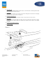
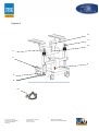
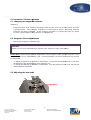
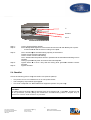
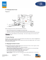
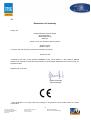
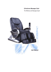
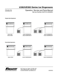
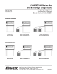
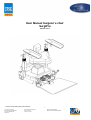
User Manual Surgeon’s chair SurgiPro Version 12-11 Product shown with optional accessories 1 GF: Jürgen Scherrieble Steuernummer 244/140/60001 VAT-No. DE232257366 HRB 9186 Deutsche Bank Regensburg BLZ 750 700 24 Kto.Nr. 32 92 935 SWIFT: DEUTDEDB750 IBAN: DE94750700240329293500 Table of contents 1. Device Safety 2. Standards and Regulations 3. Safety Precautions for Installation and Usage 3.1 General 3.2 Safe Operation 3.3 Requirements for Use 3.4 Every time before use or after alteration or modification of this device 3.5 Every time after using this device 4. Device Description 5. Preparation / Device Operation 5.1 Charging the integrated batteries 5.2 Surgeon’s Chair Adjustments 5.3 Adjusting the arm rests 5.4 Checklist 5.5 Operating Procedure 6. Device Maintenance / Miscellaneous 6.1 Safe Operation 6.2 Malfunction Troubleshooting Table 6.3 Changing Power Fuses 7. Surface Cleaning 8. Changing Functional Location 9. Accessories 10. Technical Specifications 11. Important Note 12. Declaration of Conformity 13. Maintenance 2 GF: Jürgen Scherrieble Steuernummer 244/140/60001 VAT-No. DE232257366 HRB 9186 Deutsche Bank Regensburg BLZ 750 700 24 Kto.Nr. 32 92 935 SWIFT: DEUTDEDB750 IBAN: DE94750700240329293500 1. Device Safety The medical device described in this manual was developed in full compliance with all national and international safety regulations. We guarantee through a rigorous series of tests and inspections that every device meets or exceeds the highest quality standards. We want to ensure that you are well informed of all relevant safety and handling recommendations and precautions before using this device. This chapter contains the most important technical safety information regarding this surgeon’s chair. Safety information of critical importance is contained within text boxes like the one seen here. Please give special attention to this information. Proper usage of this device is essential for both operator and patient safety. To avoid any accidents resulting from negligence or misuse, please thoroughly familiarize yourself with the contents of this manual. Please also carefully read through the service manuals of any other equipment or devices that will be used with this product. Supplementary information can be obtained from our service staff or authorized representatives. 2. Standards and Regulations • - • • • • The medical device described in this manual was constructed in compliance with the following regulations (where applicable): EN IEC In correspondence with regulations or guidelines of each country, this device m ay have to be connected to a „Special power-supply” (BEV). This product is a class 1 medical device in accordance with 93/42 /EWG. The declaration of CE-conformity contained within this service manual is only valid for new devices that come delivered with this manual. The declaration in invalid for old or used devices without the CE symbol. Please be aware of all legal requirements for accident prevention. 3. Safety Precautions for Installation and Usage 3.1 General • - • • • • Do not electrically operate any of the devices included in your shipment: In areas that are exposed to the danger of explosions In the presence of flammable anesthetic or volatile solvents such as alcohol, gas or similar substances. Do not use or store this device in a dam p room. Keep dripping, flooding or splashing water away from this device. Immediately pull the power plug if you notice any smoke, sparks or unusual smells coming from your device. Do not use the device again until after it has been examined and repaired by a member of our service team. Do not place any liquid-filled containers on this device. Make sure that no liquids can enter into electrical components of the device. Do not use excessive force when plugging in electrical components of this device 3 GF: Jürgen Scherrieble Steuernummer 244/140/60001 VAT-No. DE232257366 HRB 9186 Deutsche Bank Regensburg BLZ 750 700 24 Kto.Nr. 32 92 935 SWIFT: DEUTDEDB750 IBAN: DE94750700240329293500 • • • • • • • • • • (plugs, sockets). If you are having difficulty with a connection, be sure to double check that the plug and socket match. If you determine that the plug connection is damaged, please let our service team perform any needed repairs. Potential Equalization: Upon request, this device can be adapted with the required safeguards for „Potential Equalization”. Please inform our service staff if this is desired. Do not use cordless or cellular phones near this device. These kinds of phones are potentially dangerous for the proper functioning of medical devices. Unexpected malfunctions can appear depending on a number of on-site factors. These malfunctions are neither predictable nor assessable beforehand. Modifications to this device or any devices to be used with this device may only be performed by our service staff or authorized personal. We will not be held liable for any damages resulting from the unauthorized use or modification of this device. Any unintended use or modification of this device will immediately void all manufacturer warranties. Us e this de vic e on l y f o r its des c r ibed int ende d pur pos e. Use this device only with accessory parts that where included with your shipment. If you would like to use other accessory parts with this device, please confirm all relevant safety and compatibility requirements with the parts manufacturer. This device may only be operated by persons with the appropriate experience level or training. It is the duty of the device owner/operator to make sure that all potential users are adequately educated and trained before being allowed access to this device. Please make sure that this service manual is readily available at all times for users. Please do not pull on the power supply cable or any other cable connections. The power-plug may only be connected with a power-outlet that has proper grounding protection. 3.2 Safe Operation • This product is a premium-grade technical device. In order to ensure its flawless and safe functioning, we recommend that you allow our technicians to perform routine service and maintenance. If an error occurs that you cannot solve with the help of the malfunction troubleshooting table, please label the device as non-operative and contact our service staff immediately. 3.3 Requirements for Use Our service staff or a skilled professional recognized by our company will install your device. Please make sure that the following requirements for use are met: - All connecting parts described in this service manual, that ensure the safety and security of this device, are properly seated, screwed in and tightened. All cables and plugs are in excellent condition. The voltage settings of this device are compatible with the rated voltage of power-outlets at the installation site. While in use during a surgery, this device must not be plugged into any power-outlets, if so the emergency-stop-button should be engaged. The device must be plugged in with the specifically provided power cable. 4 GF: Jürgen Scherrieble Steuernummer 244/140/60001 VAT-No. DE232257366 HRB 9186 Deutsche Bank Regensburg BLZ 750 700 24 Kto.Nr. 32 92 935 SWIFT: DEUTDEDB750 IBAN: DE94750700240329293500 3.4 Every time before use or after alteration or modification of this device • • • • • Make sure that all requirements for use are met. Go carefully through the checklist. Refasten any removed housing, panels or screw caps. Properly close all remaining covers. Check that the power-plug is securely seated. Check that the plug of the footswitch plate (optional) is also securely seated. 3.5 Every time after using this device • • Use the emergency-stop-button to turn this device off. T he emergency-stop-button m ust always be engaged when this device is not being used. 4. Device Description This state-of-the-art surgeon’s chair is ergonomically designed to help the surgeon comfortably and effortlessly maintain correct posture, facilitating improved endurance and enhanced concentration during surgery. This surgeon’s chair has many features including: Independent electromotive height adjustment for arm supports Continuous angle and inclination adjustment for armrests Comfortable seat with height adjustable backrest Electromotive seat height adjustment Footswitch plate adapter (optional) 1. Articulating joints of the armrests The articulating joints enable full armrest adjustability in any desired direction. For making adjustments simply loosen the release lever (1.1). Using the foot-joystick (1.2) you can perform electromotive adjustment of the arm supports. 2. Armrests The armrests can be easily inclined and turned in any direction. Using levers (2.1 + 2.2) the swivel angle of the armrests can be quickly adjusted. 3. Foot switch to adjust seat height The desired seat height from 530 to 730 mm can be adjusted with electromotive power using the footswitches (3.1 + 3.2). The left footswitch (3.1) from the surgeon’s perspective moves the chair upwards. The right footswitch (3.2) from the surgeon’s perspective moves the chair downwards. 4. The Backrest The backrest can be adjusted in inclination and height. Loosen the star-knob screw (4.1) and adjust the backrest to the desired height. For inclination turn the star-knob screw (4.2) left or right. 5. Device Rating Plate Contains the electrical specifications and ratings of the device. 5 GF: Jürgen Scherrieble Steuernummer 244/140/60001 VAT-No. DE232257366 HRB 9186 Deutsche Bank Regensburg BLZ 750 700 24 Kto.Nr. 32 92 935 SWIFT: DEUTDEDB750 IBAN: DE94750700240329293500 6. The power cord The plug on the power-cord (6.1) should only be connected with a matching power-outlet that has proper grounding protection. 7. Power fuses The correct fuse ratings can be found on the device rating plate. Instructions for changing the power fuses can be found in chapter 6.3. 8. Emergency-stop-button (8) The electrical supply of the surgeon’s chair can be turned on and off here. 9. Brake Pedal Push down the red brake Pedal (9.2) with your foot to secure the chair firmly in place. Pushing down the green pedal (9.1) releases the brakes and the chair is once again moveable. 10. Footswitch Plate Adapter (Optional) 11. Charging Indicator Diagram 2 2.1 1 2.2 1.1 9.2 3.1 1.2 10 3.2 9.1 6 GF: Jürgen Scherrieble Steuernummer 244/140/60001 VAT-No. DE232257366 HRB 9186 Deutsche Bank Regensburg BLZ 750 700 24 Kto.Nr. 32 92 935 SWIFT: DEUTDEDB750 IBAN: DE94750700240329293500 Diagram 3 4.1 1.1 4.2 1.1 11 8 6 8 6.1 7 GF: Jürgen Scherrieble Steuernummer 244/140/60001 VAT-No. DE232257366 HRB 9186 Deutsche Bank Regensburg BLZ 750 700 24 Kto.Nr. 32 92 935 SWIFT: DEUTDEDB750 IBAN: DE94750700240329293500 5. Preparation / Device Operation 5.1 Charging the integrated batteries (Diagram 3) • Plug the power-cord cord into the charging socket on the chair (6) and the other end into a power-outlet. The charging indicator (11) will light-up up green, indicating that the batteries are being charged. charged If the charging indicator (11) does not light up, check to see if the emergency-stop stop-button is engaged (8). 5.2 Surgeon’s Chair Adjustments • Release the emergency-stop top-button (8). CAUTION: Watch out for crush hazards when adjusting the surgeon’s chair downwards! wards! Please Note: Electromotive up/down adjustment of this surgeon’s chair and arm supports is only designed to be run for a limited duty cycle. Thermal problems can arise if the motors are overrun or overloaded. • • To adjust the backrest ackrest (4) upwards or downwards: Loosen the star-knob knob screw (4.1) and move the backrest to the desired height, height then retighten (4.1). To incline the backrest krest (4) forwards or backwards: Turn the star-knob knob screw (4.2) and until the desired position is reached. 5.3 Adjusting the arm rests Screw A 8 GF: Jürgen Scherrieble Steuernummer 244/140/60001 VAT-No. DE232257366 HRB 9186 Deutsche Bank Regensburg BLZ 750 700 24 Kto.Nr. 32 92 935 SWIFT: DEUTDEDB750 IBAN: DE94750700240329293500 Screw C Screw B Screw C Step 1: Step 2: Loosen Screw A (Safety Screw). Screw B adjusts the tightness of the lever that locks the ball-and-socket ball socket joint in place. - Loosen Screw B until the lever is resting on the plate. Step 3: The C Screws adjust the load-bearing load capacity of the armrest. Tighten screws = firmer load-bearing load Loosen screws = softer load-bearing load The C Screws must be quarter turned in parallel until the desired load-bearing load level is reached. Testing is possible only after all screws have been adjusted. Tighten Screw B in such a way that the locking locking lever generates sufficient counter pressure. Tighten Screw A . Step 4: Step 5: 5.4 Checklist Check the following points every time before use (without patient): • • • The power-cord is not connected to an on-site on power-outlet! The emergency stop button is (8) engaged. The chair is adjusted in a comfortable and supportive position for your body. body CAUTION: For safety reasons the chair must not be used ifi any of its functions fail. If possible, diagnose and fix any problems yourself (using using the malfunction troubleshooting table in chapter 6.2) or contact our service team ass soon as possible. possible 9 GF: Jürgen Scherrieble Steuernummer 244/140/60001 VAT-No. DE232257366 HRB 9186 Deutsche Bank Regensburg BLZ 750 700 24 Kto.Nr. 32 92 935 SWIFT: DEUTDEDB750 IBAN: DE94750700240329293500 5.5 Operating Procedure • • • • • Inspect the surgeon’s chair using the checklist. Move the surgeon’s chair to the location where it will be used. Engage the brake pedal (9.2) to secure the surgeon’s chair in place. If necessary, readjust the seat height to ensure the correct distance from the foot controls, and then readjust the backrest and armrests. The emergency-stop-button (8) must be engaged if the surgeon’s chair is not being used. CAUTION: The batteries are not being charged if the emergency-stop-button is engaged. 6. Device Maintenance / Miscellaneous 6.1 Safe Operation This product is a premium-grade technical device. In order to ensure flawless and safe functioning, we recommend that you allow our technicians to perform routine service and maintenance. 6.2 Malfunction Troubleshooting Table If an error occurs that you cannot solve with the help of the malfunction troubleshooting table, please label the device as non-operative and contact our service staff immediately. MALFUNCTION Electromotive height adjustment of the chair does not function: POSSIBLE CAUSE Defective foot control Contact Service Staff Emergency-stop-button is engaged Battery charge is low Electromotive height adjustment of the arm supports does not function: Release Contact Service Staff Defective lifting column Contact Service Staff Defective control box Contact Service Staff Defective joystick Contact Service Staff Emergency-stop-button is engaged Release Battery charge is low Deutsche Bank Regensburg BLZ 750 700 24 Kto.Nr. 32 92 935 Contact Service Staff Defective drive Contact Service Staff Defective control box Contact Service Staff 10 GF: Jürgen Scherrieble Steuernummer 244/140/60001 VAT-No. DE232257366 HRB 9186 SOLUTION SWIFT: DEUTDEDB750 IBAN: DE94750700240329293500 6.3 Changing Power Fuses Diagram 4 6 8 When changing power fuses, please follow these instructions: • • • Make sure that the device is not plugged into a power-outlet. Remove all necessary screws and panels (8) and then take out the defective fuses. Install the new fuses and then replace and secure all previously removed panels and screws (8). Please Note: Pay careful attention to the fuse ratings. The correct ratings can be found on the device rating plate. 7. Surface Cleaning All parts of this surgeon’s chair can be wiped clean with a damp cloth. The use of aggressive or abrasive cleaning agents should be avoided. Wipe away possible residues with a mix of equal parts alcohol and distilled water, and a spritz of commercial quality detergent. 8. Changing Functional Location Following these instructions when changing the functional location of the surgeon’s chair: Engage the emergency-stop-button (8) Press down the green pedal (9.1) to release the brakes. Make sure there is sufficient space when moving the chair through doors or narrow passages. Avoid any kind of bumping, shoving or jolting. Do not move this chair over thresholds, steps or uneven surfaces. Move this chair over inclined surfaces with great caution. Do not park this chair on an inclined surface. When the new location has been reached push the brake pedal (9.2) to secure the chair in place. 11 GF: Jürgen Scherrieble Steuernummer 244/140/60001 VAT-No. DE232257366 HRB 9186 Deutsche Bank Regensburg BLZ 750 700 24 Kto.Nr. 32 92 935 SWIFT: DEUTDEDB750 IBAN: DE94750700240329293500 9. Accessories Please note: Use this device only with accessory parts that where included in your shipment. If you would like to use other accessory parts with this device, please confirm all relevant safety and compatibility requirements with the parts manufacturer. 10. Technical Specifications Base Area: Armrests: Backrest: Seat Height: Seat Height adjustment: Arm Supports Height adjustment: Chassis: Weight: Power supply: Nominal Frequency: Power input: Short-term load: Power fuse rating: Electrical Specs: 630mm x 765mm (max.) With joints adjustable in all directions. Adjustable in height and inclination min. 553mm, max. 753mm. Electromotive, Lifting 200 mm. Electromotive, Lifting 200 mm. Central brake effective on all four double-wheel casters. One of the casters has anti-static protection. 60kg 100-110/120/125/230/240 V ± 10% 50...60 Hz 12VA Lifting column - 2min Height adjustment for arm supports - 2min 250V T2,5A According to IEC 601-1/EN 60 601-1 / VDE 0750, Part1, Protection class 1, Type B, Degree of protection IPX4 Ambient Conditions For Operation: Temperature +10°C… +40°C Rel. Humidity 30%...75% Air pressure 700hPa…1060hPa Ambient Conditions For transport and storage in shipment packaging: Temperature -40°C… +70°C Rel. Humidity 10%...100% (without condensation) Air pressure 500hPa…1060hPa We reserve the right to alter or modify the construction of this product and included parts at any time. 11. Important Note The following items are excluded from the warranty: All upholstery elements Paintwork defects All damages suggesting inappropriate operation of the equipment by the user. Batteries 12 GF: Jürgen Scherrieble Steuernummer 244/140/60001 VAT-No. DE232257366 HRB 9186 Deutsche Bank Regensburg BLZ 750 700 24 Kto.Nr. 32 92 935 SWIFT: DEUTDEDB750 IBAN: DE94750700240329293500 12. Declaration of Conformity hereby, we UFSK-International OSYS GmbH Kirchhoffstraße 1 93055 Regensburg Germany declare on our own authority, that the product Surgeon’s chair Model surgiPro is conform with the following conformity assessment procedure attachment VII according to the rules of the directive 93/42/EEC of the council dated 14. June 1993 for Medical Devices, last amendment by directive 2007/47/EC of the European Parliament and of the Council of 5 September 2007. Regensburg, 01.05.2011 Jürgen Scherrieble General Manager This declaration is no longer valid if any change on the products will be made without our written confirmation. 13 GF: Jürgen Scherrieble Steuernummer 244/140/60001 VAT-No. DE232257366 HRB 9186 Deutsche Bank Regensburg BLZ 750 700 24 Kto.Nr. 32 92 935 SWIFT: DEUTDEDB750 IBAN: DE94750700240329293500 13. Maintenance For technical inquiries, customer service issues and spare parts orders, please contact us at: UFSK-International OSYS GmbH Kirchhoffstraße 1 93055 Regensburg Germany Tel. +49 941/78862-15 Fax. +49 941/78862-35 e-mail: [email protected] www.ufsk-osys.com 14 GF: Jürgen Scherrieble Steuernummer 244/140/60001 VAT-No. DE232257366 HRB 9186 Deutsche Bank Regensburg BLZ 750 700 24 Kto.Nr. 32 92 935 SWIFT: DEUTDEDB750 IBAN: DE94750700240329293500