1
Agilent
N8211A/N8212A
Performance
Upconverter Synthetic
Instrument Modules,
250 kHz to 20 / 40 GHz
SCPI Programming Guide
Edition, January 15, 2008
N8212-90008
Agilent Technologies
Notices
© Agilent Technologies, Inc. 2008
Manual Part Number
No part of this manual may be reproduced
in any form or by any means (including
electronic storage and retrieval or translation into a foreign language) without prior
agreement and written consent from Agilent Technologies, Inc. as governed by
United States and international copyright
laws.
N8212-90008
Edition
Edition, January 15, 2008
Printed in USA
Windows®
Agilent Technologies, Inc.
1400 Fountaingrove Pkwy
Santa Rosa, CA 95403
Adobe Acrobat Reader®
Warranty
The material contained in this document is provided “as is,” and is
subject to being changed, without
notice, in future editions. Further,
to the maximum extent permitted
by applicable law, Agilent disclaims
all warranties, either express or
implied, with regard to this manual
and any information contained
herein, including but not limited to
the implied warranties of merchantability and fitness for a particular purpose. Agilent shall not
be liable for errors or for incidental
or consequential damages in connection with the furnishing, use, or
performance of this document or of
any information contained herein.
Should Agilent and the user have a
separate written agreement with
warranty terms covering the material in this document that conflict
with these terms, the warranty
terms in the separate agreement
shall control.
Technology Licenses
The hardware and/or software described
in this document are furnished under a
license and may be used or copied only in
accordance with the terms of such license.
Restricted Rights Legend
If software is for use in the performance
of a U.S. Government prime contract or
subcontract, Software is delivered and
licensed as “Commercial computer software” as defined in DFAR 252.227-7014
(June 1995), or as a “commercial item” as
defined in FAR 2.101(a) or as “Restricted
computer software” as defined in FAR
52.227-19 (June 1987) or any equivalent
agency regulation or contract clause. Use,
duplication or disclosure of Software is
subject to Agilent Technologies’ standard
commercial license terms, and non-DOD
Departments and Agencies of the U.S.
Government will receive no greater than
Restricted Rights as defined in FAR
52.227-19(c)(1-2) (June 1987). U.S. Government users will receive no greater than
Limited Rights as defined in FAR
52.227-14 (June 1987) or DFAR
252.227-7015 (b)(2) (November 1995), as
applicable in any technical data.
Safety Notices
A CAUTION notice denotes a
hazard. It calls attention to an
operating procedure, practice,
or the like that, if not correctly
performed or adhered to, could
result in damage to the product
or loss of important data. Do
not proceed beyond a
CAUTION notice until the
indicated conditions are fully
understood and met.
A WARNING notice denotes
a hazard. It calls attention to
an operating procedure,
practice, or the like that, if
not correctly performed or
adhered to, could result in
personal injury or death. Do
not proceed beyond a
WARNING notice until the
indicated conditions are fully
understood and met.
Introducing the N8211A/N8212A Performance Upconverter
The Agilent Technologies N8211A performance analog upconverter is a synthetic
instrument module that translates low-frequency input signals to an output range
reaching 20 or 40 GHz. It provides signal bandwidth to support amplitude modulation
(AM), frequency modulation (FM), and pulse modulation without contributing
additional noise to the original signal source (typically an analog signal generator).
The Agilent Technologies N8212A performance vector upconverter is a synthetic
instrument module that translates low-frequency input signals to output signals up to
20 GHz with AM, FM, and pulse modulation. The N8212A also supports an I and Q
modulation bandwidth of better than 1 GHz for true wideband signal generation.
Agilent's synthetic instrument family offers the highest-performing RF/MW LAN-based
modular instrumentation and the smallest footprint for automated test systems; providing
the maximum flexibility and minimizing the cost of an ATS over its lifetime.
Agilent’s synthetic instrument modules use LAN eXtension for Instrumentation (LXI)
modular format. LXI differs from other modular formats (such as VXI and PXI) by using
an external computer and local area network (LAN), rather than embedded computers,
for control.
The LXI standard supports the IEEE 1588 time synchronization and protocol standard,
which allows synchronous triggering of different instruments, even with different-length
LAN cables. The IEEE 1588 precision time protocol (PTP) enables a common sense of
time over a distributed system.
Synthetic instrument modules offered by Agilent Technologies include the following:
• N8201A performance downconverter, 3 Hz to 26.5 GHz
• N8211A performance analog upconverter, 250 kHz to 20 / 40 GHz
• N8212A performance vector upconverter, 250 kHz to 20 GHz
• N8221A IF digitizer, 30 MS/s
• N8241A arbitrary waveform generator, 15-Bit, 1.25 GS/s or 625 MS/s
• N8242A arbitrary waveform generator, 10-Bit, 1.25 GS/s or 625 MS/s
For further information, refer to:
http://www.agilent.com/find/synthetic
Agilent N8211A/N8212A Performance Upconverter Synthetic Instrument Module, 250 kHz to 20 / 40 GHz
3
4
Agilent N8211A/N8212A Performance Upconverter Synthetic Instrument Module, 250 kHz to 20 / 40 GHz
Contents
Introducing the N8211A/N8212A Performance Upconverter
3
1 Getting Started with Remote Operation
Programming and Software/Hardware Layers
LAN Interface
18
19
IO Libraries and Programming Languages
20
Agilent IO Libraries Suite
20
Windows NT™ and Agilent IO Libraries M (and Earlier)
Selecting IO Libraries for LAN
22
Programming Languages
22
20
Error Messages
23
Error Message File
23
Error Message Types
23
2 Using the LAN Interface
Using LAN
26
Connect LAN Cables and Turn On Power
27
Connect to a LAN with a Cross-Over LAN Cable
Verify Connection with Synthetic Instrument Finder
Verifying LAN Functionality
31
28
30
Using VXI-11
33
Configuring for VXI-11
33
Using Sockets LAN
33
Using Telnet LAN
34
Using FTP
36
Troubleshooting
37
Alternative Ways to Verify Connectivity to the PC
37
How to Use the Synthetic Instrument Finder
37
How to Reset the LAN Configuration
39
How to Set a Static IP Address
41
How to Determine a PCs Configuration Settings
45
If the Instrument was Unable to Join the LAN
46
If the LAN LED is Red
46
If the Instrument’s IP Address or Hostname Cannot be Found with Ping
If the Instrument is Not Found by the Synthetic Instrument Finder
48
If the Instrument’s Hostname and PC Cannot Communicate
48
46
Agilent N8211A/N8212A Performance Upconverter Synthetic Instrument Module, 250 kHz to 20 / 40 GHz
5
If the Instrument Web Page is Not Visible
48
If the Software Driver Will Not Open the Connection
49
3 Programming Examples
Using the Programming Interface Examples
52
Programming Examples Development Environment
Running C++ Programs
52
Running C# Examples
53
Running Basic Examples
53
Running Java Examples
53
Running Perl Examples
54
52
LAN Programming Interface Examples
55
VXI-11 Programming
55
VXI-11 Programming Using SICL and C++
55
VXI-11 Programming Using VISA and C++
58
Sockets LAN Programming and C
60
Queries for Lan Using Sockets
63
Sockets LAN Programming Using Java
91
Sockets LAN Programming Using PERL
94
4 Programming the Status Register System
Overview
98
Overall Status Byte Register Systems
99
Status Register Bit Values
101
Example: Enable a Register
101
Example: Query a Register
101
Accessing Status Register Information
102
Determining What to Monitor
102
Deciding How to Monitor
102
Status Register SCPI Commands
105
Status Byte Group
107
Status Byte Register
108
Service Request Enable Register
108
Status Groups
110
Standard Event Status Group
110
Standard Operation Status Group
112
Data Questionable Status Group
115
Data Questionable Power Status Group
118
Data Questionable Frequency Status Group
121
6
Agilent N8211A/N8212A Performance Upconverter Synthetic Instrument Module, 250 kHz to 20 / 40 GHz
Data Questionable Modulation Status Group
Data Questionable Calibration Status Group
124
126
5 Creating and Downloading User-Data Files
Overview
132
Save and Recall Instrument State Files
133
Save and Recall SCPI Commands
133
Save and Recall Programming Example Using VISA and C#
User Flatness Correction Downloads Using C++ and VISA
133
147
6 SCPI Basics
How the SCPI Information is Organized
154
SCPI Listings
154
Subsystem Groupings by Chapter
154
Supported Models and Options per Command
154
SCPI Basics
155
Common Terms
155
Command Syntax
155
Command Types
157
Command Tree
158
Command Parameters and Responses
158
Program Messages
163
File Name Variables
164
MSUS (Mass Storage Unit Specifier) Variable
165
Quote Usage with SCPI Commands
166
Binary, Decimal, Hexadecimal, and Octal Formats
167
7 System Commands
Calibration Subsystem (:CALibration)
:DCFM
170
:IQ
170
:IQ:DC
170
:IQ:DEFault
171
:IQ:FULL
171
:IQ:STARt
171
:IQ:STOP
172
:WBIQ
172
:WBIQ:DC
172
:WBIQ:DEFault
173
:WBIQ:FULL
173
170
Agilent N8211A/N8212A Performance Upconverter Synthetic Instrument Module, 250 kHz to 20 / 40 GHz
7
:WBIQ:STARt
:WBIQ:STOP
173
174
Diagnostic Subsystem (:DIAGnostic[:CPU]:INFOrmation)
:BOARds
175
:CCOunt:ATTenuator
175
:CCOunt:PON
175
:DISPlay:OTIMe
175
:LICENse:AUXiliary
175
:OPTions
176
:OPTions:DETail
176
:OTIMe
176
:REVision
176
:SDATe
176
175
Display Subsystem (:DISPlay)
177
:ANNotation:AMPLitude:UNIT
177
IEEE 488.2 Common Commands
*CLS
178
*ESE
178
*ESE?
178
*ESR
179
*ESR?
179
*IDN?
179
*OPC
179
*OPC?
179
*PSC
180
*PSC?
180
*RCL
180
*RST
181
*SAV
181
*SRE
181
*SRE?
181
*STB?
182
*TRG
182
*TST?
182
*WAI
183
178
Low-Band Filter Subsystem
184
[:SOURce]:LBFilter
184
Memory Subsystem (:MEMory)
:CATalog:BINary
185
:CATalog:STATe
185
8
185
Agilent N8211A/N8212A Performance Upconverter Synthetic Instrument Module, 250 kHz to 20 / 40 GHz
:CATalog:UFLT
185
:CATalog[:ALL]
186
:COPY[:NAME]
186
:DATA:APPend
186
:DELete:ALL
187
:DELete:BINary
187
:DELete:LIST
188
:DELete:STATe
188
:DELete:UFLT
188
:DELete[:NAME]
188
:FREE[:ALL]
188
:LOAD:LIST
189
:MOVE
189
:STATe:COMMent
189
:STORe:LIST
190
Mass Memory Subsystem (:MMEMory)
:CATalog
191
:COPY
191
:DELete[:NAME]
192
:HEADer:CLEar
192
:HEADer:DESCription
193
:LOAD:LIST
193
:MOVE
194
:STORe:LIST
194
191
Output Subsystem (:OUTPut)
195
:BLANking:AUTO
195
:BLANking:[STATe]
195
:MODulation[:STATe]
196
[:STATe]
196
Status Subsystem (:STATus)
197
:OPERation:CONDition
197
:OPERation:ENABle
197
:OPERation:NTRansition
198
:OPERation:PTRansition
198
:OPERation[:EVENt]
199
:PRESet
199
:QUEStionable:CALibration:CONDition
199
:QUEStionable:CALibration:ENABle
199
:QUEStionable:CALibration:NTRansition
200
:QUEStionable:CALibration:PTRansition
200
Agilent N8211A/N8212A Performance Upconverter Synthetic Instrument Module, 250 kHz to 20 / 40 GHz
9
:QUEStionable:CALibration[:EVENt]
201
:QUEStionable:CONDition
201
:QUEStionable:ENABle
202
:QUEStionable:FREQuency:CONDition
202
:QUEStionable:FREQuency:ENABle
202
:QUEStionable:FREQuency:NTRansition
203
:QUEStionable:FREQuency:PTRansition
203
:QUEStionable:FREQuency[:EVENt]
204
:QUEStionable:MODulation:CONDition
204
:QUEStionable:MODulation:ENABle
205
:QUEStionable:MODulation:NTRansition
205
:QUEStionable:MODulation:PTRansition
206
:QUEStionable:MODulation[:EVENt]
206
:QUEStionable:NTRansition
207
:QUEStionable:POWer:CONDition
207
:QUEStionable:POWer:ENABle
207
:QUEStionable:POWer:NTRansition
208
:QUEStionable:POWer:PTRansition
208
:QUEStionable:POWer[:EVENt]
209
:QUEStionable:PTRansition
209
:QUEStionable[:EVENt]
210
System Subsystem (:SYSTem)
211
:ALTernate
211
:ALTernate:STAte
211
:CAPability
211
:ERRor[:NEXT]
212
:ERRor:SCPI[:SYNTax]
212
:IDN
212
:OEMHead:FREQuency:STARt
213
:OEMHead:FREQuency:STOP
213
:OEMHead:SELect
213
:OEMHead:FREQuency:BAND WR15|WR12|WR10|WR8|WR6|WR5|WR3
:OEMHead:FREQuency:MULTiplier
215
:PON:TYPE
215
:PRESet
216
:PRESet:ALL
216
:PRESet:PERSistent
216
:PRESet:PN9
216
:PRESet:TYPE
217
:PRESet[:USER]:SAVE
217
:SECurity:ERASeall
217
10
Agilent N8211A/N8212A Performance Upconverter Synthetic Instrument Module,
214
:SECurity:LEVel
217
:SECurity:LEVel:STATe
218
:SECurity:OVERwrite
219
:SECurity:SANitize
219
:VERSion
220
Trigger Subsystem
221
:ABORt
221
:INITiate:CONTinuous[:ALL]
221
:INITiate[:IMMediate][:ALL]
221
:TRIGger:OUTPut:POLarity
222
:TRIGger[:SEQuence]:SLOPe
222
:TRIGger[:SEQuence]:SOURce
222
:TRIGger[:SEQuence][:IMMediate]
223
Unit Subsystem (:UNIT)
:POWer
224
224
8 Basic Function Commands
Correction Subsystem ([:SOURce]:CORRection)
:FLATness:LOAD
226
:FLATness:PAIR
226
:FLATness:POINts
227
:FLATness:PRESet
227
:FLATness:STORe
227
[:STATe]
227
226
Frequency Subsystem ([:SOURce])
229
:FREQuency:CENTer
229
:FREQuency:CHANnels:BAND
229
:FREQuency:CHANnels:NUMBer
231
:FREQuency:CHANnels[:STATe]
232
:FREQuency:FIXed
232
:FREQuency:MANual
233
:FREQuency:MODE
234
:FREQuency:MULTiplier
235
:FREQuency:OFFSet
235
:FREQuency:OFFSet:STATe
236
:FREQuency:REFerence
236
:FREQuency:REFerence:SET
236
:FREQuency:REFerence:STATe
237
:FREQuency:SPAN
237
:FREQuency:STARt
238
Agilent N8211A/N8212A Performance Upconverter Synthetic Instrument Module, 250 kHz to 20 / 40 GHz
11
:FREQuency:STOP
238
:FREQuency[:CW]
239
:FREQuency[:CW]:STEP[:INCRement]
239
:PHASe:REFerence
240
:PHASe[:ADJust]
240
:ROSCillator:BANDwidth:DEFaults
240
:ROSCillator:BANDwidth:EXTernal
241
:ROSCillator:BANDwidth:INTernal
241
:ROSCillator:SOURce
241
:ROSCillator:SOURce:AUTO
241
List/Sweep Subsystem ([:SOURce])
243
:LIST:DIRection
243
:LIST:DWELl
244
:LIST:DWELl:POINts
244
:LIST:DWELl:TYPE
245
:LIST:FREQuency
245
:LIST:FREQuency:POINts
246
:LIST:MANual
246
:LIST:MODE
247
:LIST:POWer
247
:LIST:POWer:POINts
248
:LIST:RETRace
248
:LIST:TRIGger:SOURce
248
:LIST:TYPE
249
:LIST:TYPE:LIST:INITialize:FSTep
249
:LIST:TYPE:LIST:INITialize:PRESet
250
:SWEep:CONTrol:STATe
250
:SWEep:CONTrol:TYPE
250
:SWEep:DWELl
251
:SWEep:GENeration
251
:SWEep:MODE
252
:SWEep:POINts
252
SWEep:TIME
253
:SWEep:TIME:AUTO
253
Marker Subsystem–Option 007 ([:SOURce])
255
:MARKer:AMPLitude[:STATe]
255
:MARKer:AMPLitude:VALue
255
:MARKer:AOFF
255
:MARKer:DELTa?
256
:MARKer[0,1,2,3,4,5,6,7,8,9]:FREQuency
256
:MARKer:MODe
257
12
Agilent N8211A/N8212A Performance Upconverter Synthetic Instrument Module,
:MARKer:REFerence
257
:MARKer[0,1,2,3,4,5,6,7,8,9][:STATe]
257
Power Subsystem ([:SOURce]:POWer)
259
:ALC:BANDwidth|BWIDth
259
:ALC:BANDwidth|BWIDth:AUTO
259
:ALC:LEVel
260
:ALC:SEARch
260
:ALC:SEARch:REFerence
261
:ALC:SEARch:SPAN:START
261
:ALC:SEARch:SPAN:STOP
261
:ALC:SEARch:SPAN:TYPE FULL|USER
262
:ALC:SEARch:SPAN[:STATe] ON|OFF|1|0
262
:ALC:SOURce
262
:ALC:SOURce:EXTernal:COUPling
263
:ALC[:STATe]
263
:ATTenuation
264
:ATTenuation:AUTO
264
:MODE
265
:PROTection:STATe
266
:REFerence
266
:REFerence:STATe
267
:STARt
267
:STOP
268
[:LEVel][:IMMediate]:OFFSet
268
[:LEVel][:IMMediate][:AMPLitude]
269
Trigger Sweep Subsystem ([:SOURce])
:TSWeep
270
270
9 Analog Commands
Amplitude Subsystem ([:SOURce])
272
:AM[1]|2
272
:AM:INTernal:FREQuency:STEP[:INCRement]
272
:AM:MODE
273
:AM:WIDeband:SENSitivity
273
:AM:WIDeband:STATe
274
:AM[1]|2:EXTernal[1]|2:COUPling
274
:AM[1]|2:EXTernal[1]|2:IMPedance
274
:AM[1]|2:INTernal[1]|2:FREQuency
275
:AM[1]|2:INTernal[1]:FREQuency:ALTernate
276
:AM[1]|2:INTernal[1]:FREQuency:ALTernate:AMPLitude:PERCent
276
Agilent N8211A/N8212A Performance Upconverter Synthetic Instrument Module, 250 kHz to 20 / 40 GHz
13
:AM[1]|2:INTernal[1]|2:FUNCtion:NOISe
277
:AM[1]|2:INTernal[1]|2:FUNCtion:SHAPe
277
:AM[1]|2:INTernal[1]:SWEep:RATE
277
:AM[1]|2:INTernal[1]:SWEep:TRIGger
278
:AM[1]|2:SOURce
278
:AM[1]|2:STATe
279
:AM[1]|2:TYPE
279
:AM[1]|2[:DEPTh]:EXPonential
280
:AM[1]|2[:DEPTh][:LINear]
280
:AM[1]|2[:DEPTh][:LINear]:TRACk
281
:AM[:DEPTh]:STEP[:INCRement]
281
Frequency Modulation Subsystem ([:SOURce])
283
:FM[1]|2
283
:FM:INTernal:FREQuency:STEP[:INCRement]
283
:FM[1]|2:EXTernal[1]|2:COUPLing
284
:FM[1]|2:EXTernal[1]|2:IMPedance
284
:FM[1]|2:INTernal[1]:FREQuency:ALTernate
284
:FM[1]|2:INTernal[1]:FREQuency:ALTernate:AMPLitude:PERCent
:FM[1]|2:INTernal[1]:SWEep:RATE
285
:FM[1]|2:INTernal[1]:SWEep:TRIGger
286
:FM[1]|2:INTernal[1]|2:FREQuency
286
:FM[1]|2:INTernal[1]|2:FUNCtion:NOISe
287
:FM[1]|2:INTernal[1]|2:FUNCtion:RAMP
287
:FM[1]|2:INTernal[1]|2:FUNCtion:SHAPe
288
:FM[1]|2:SOURce
288
:FM[1]|2:STATe
289
:FM[1]|2[:DEViation]
289
:FM[1]|2[:DEViation]:TRACk
290
Low Frequency Output Subsystem ([:SOURce]:LFOutput)
291
:LFOutput:AMPLitude
291
:LFOutput:FUNCtion[1]|2:FREQuency
291
:LFOutput:FUNCtion[1]:FREQuency:ALTernate
292
:LFOutput:FUNCtion[1]:FREQuency:ALTernate:AMPLitude:PERCent
:LFOutput:FUNCtion[1]|2:SHAPe
293
:LFOutput:FUNCtion:[1]|2:SHAPe:NOISe
293
:LFOutput:FUNCtion[1]|2:SHAPe:RAMP
293
:LFOutput:FUNCtion[1]:SWEep:RATE
294
:FUNCtion[1]:SWEep:TRIGger
294
:LFOutput:SOURce
295
14
Agilent N8211A/N8212A Performance Upconverter Synthetic Instrument Module,
285
292
:LFOutput:STATe
295
Phase Modulation Subsystem ([:SOURce])
297
:PM[1]|2
297
:PM:INTernal:FREQuency:STEP[:INCRement]
297
:PM[1]|2:BANDwidth|BWIDth
298
:PM[1]|2:EXTernal[1]|2:COUPling
298
:PM[1]|2:EXTernal[1]|2:IMPedance
299
:PM[1]|2:INTernal[1]:FREQuency
299
PM[1]|2:INTernal[1]:FREQuency:ALTernate
299
:PM[1]|2:INTernal[1]|2:FUNCtion:NOISe
300
:PM[1]|2:INTernal[1]|2:FUNCtion:RAMP
300
:PM[1]|2:INTernal[1]:FREQuency:ALTernate:AMPLitude:PERCent
:PM[1]|2:INTernal[1]:FUNCtion:SHAPe
301
PM[1]|2:INTernal2:FUNCtion:SHAPe
302
:PM[1]|2:INTernal[1]:SWEep:RATE
302
:PM[1]|2:INTernal[1]:SWEep:TRIGger
302
:PM[1]|2:SOURce
303
:PM[1]|2:STATe
303
:PM[1]|2[:DEViation]
304
:PM[1]|2[:DEViation]:TRACk
305
:PM[:DEViation]:STEP[:INCRement]
306
Pulse Modulation Subsystem ([:SOURce])
307
:PULM:EXTernal:POLarity NORMal:INVerted
:PULM:INTernal[1]:DELay
307
:PULM:INTernal[1]:DELay:STEP
308
:PULM:INTernal[1]:FREQuency
308
:PULM:INTernal[1]:FREQuency:STEP
309
:PULM:INTernal[1]:PERiod
309
:PULM:INTernal[1]:PERiod:STEP[:INCRement]
:PULM:INTernal[1]:PWIDth
310
:PULM:INTernal[1]:PWIDth:STEP
311
:PULM:INTernal
311
:PULM:SOURce
312
:PULM:STATe
312
301
307
310
10 Digital Modulation Commands
Digital Modulation Subsystem ([:SOURce]:DM)
:EXTernal:Filter
314
:EXTernal:Filter:AUTO
314
:EXTernal:HCRest
315
314
Agilent N8211A/N8212A Performance Upconverter Synthetic Instrument Module, 250 kHz to 20 / 40 GHz
15
:EXTernal:POLarity
315
:EXTernal:SOURce
315
:IQADjustment:DELay
316
:IQADjustment:EXTernal:COFFset
317
:IQADjustment:EXTernal:DIOFfset
317
:IQADjustment:EXTernal:DQOFfset
318
:IQADjustment:EXTernal:GAIN
318
:IQADjustment:EXTernal:IOFFset
319
:IQADjustment:EXTernal:IQATten
319
:IQADjustment:EXTernal:QOFFset
320
:IQADjustment:GAIN
320
:IQADjustment:IOFFset
321
:IQADjustment:QOFFset
321
:IQADjustment:QSKew
322
:IQADjustment:SKEW
322
:IQADjustment:SKEW:Path
323
:IQADjustment[:STATe]
324
:MODulation:ATTen
324
:MODulation:ATTen:AUTO
325
:MODulation:ATTen:EXTernal
325
:MODulation:ATTenn:EXTernal:LEVel
326
:MODulation:ATTenn:EXTernal:LEVel:MEASurement
:MODulation:ATTen:OPTimize:BANDwidth
326
:MODulation:FILTer
327
:MODulation:FILTer:AUTO
327
:POLarity[:ALL]
328
:SKEW:PATH
328
:SKEW[:STATe]
329
:SOURce
329
:SRATio
330
:STATe
330
Wideband Digital Modulation Subsystem ([:SOURce]:WDM)
:IQADjustment:IOFFset
331
:IQADjustment:QOFFset
331
:IQADjustment[:STATe]
332
16
326
331
Agilent N8211A/N8212A Performance Upconverter Synthetic Instrument Module,
SCPI Programming Guide
1
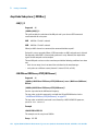
Getting Started with Remote Operation
“Programming and Software/Hardware Layers" on page 18
“LAN Interface" on page 19
“IO Libraries and Programming Languages" on page 20
“Error Messages" on page 23
Agilent Technologies
17
1
Getting Started with Remote Operation
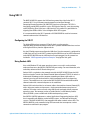
Programming and Software/Hardware Layers
The Agilent Technologies N8211A performance analog upconverter or Agilent Technologies
N8212A performance vector upconverter support LAN serial connection.
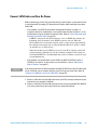
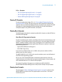
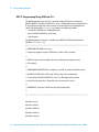
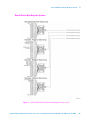
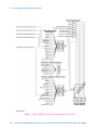
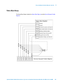
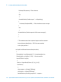
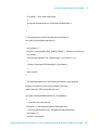
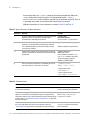
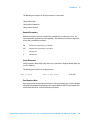
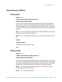
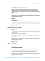
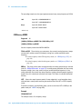
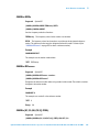
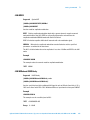
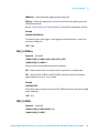
Use the LAN interface, in combination with IO libraries and programming languages, to
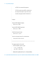
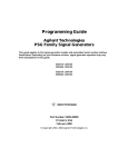
remotely control an N8211A/N8212A. Figure 1 uses LAN as an example of the relationships
between the interface, IO libraries, programming language, and N8211A/N8212A.
Figure 1
18
Software/Hardware Layers
Agilent N8211A/N8212A Performance Upconverter Synthetic Instrument Module, 250 kHz to 20 / 40 GHz
Getting Started with Remote Operation
1
LAN Interface
Data transfer using the LAN is as fast as the LAN handles packets of data. The single cable
distance between a computer and the N8211A/N8212A is limited to 100 meters (100Base-T
and 10Base-T).
The N8211A/N8212A is designed to connect with a 10Base-T LAN. Where auto-negotiation
is present, the N8211A/N8212A can connect to a 100Base-T LAN, but communicate at
10Base-T speeds. For more information on LAN communication refer to
http://www.ieee.org.
The following protocols can be used to communicate with the N8211A/N8212A over the
LAN:
• VXI-11 (recommended)
• Sockets
• TELNET
• FTP
For more information on configuring the N8211A/N8212A to communicate over the LAN, refer to
“Using LAN" on page 26.
Agilent N8211A/N8212A Performance Upconverter Synthetic Instrument Module, 250 kHz to 20 / 40 GHz
19
1
Getting Started with Remote Operation
IO Libraries and Programming Languages
The IO libraries is a collection of functions used by a programming language to send
instrument commands and receive instrument data. Before you can communicate and
control the N8211A/N8212A, you must have an IO library installed on your computer. The
Agilent IO libraries are included on an Automation-Ready CD with your N8211A/N8212A, or
they can be downloaded from the Agilent website: http://www.agilent.com.
To learn about using IO libraries with Windows XP™ or newer operating systems, refer to
the Agilent IO Libraries Suite’s help located on the Automation-Ready CD that ships with
your N8211A/N8212A. Other sources of this information, can be downloaded from the
Agilent website: http://www.agilent.com.
To better understand setting up Windows XP™ operating systems and newer, using PC LAN
port settings, refer to “Using the LAN Interface" on page 25.
Agilent IO Libraries Suite
The Agilent IO Libraries Suite replaces earlier versions of the Agilent IO Libraries. Agilent IO
Libraries Suite does not support Windows NT™. If you are using the Windows NT platform,
you must use Agilent IO Libraries version M or earlier.
Windows 98™ and Windows ME™ are not supported in the Agilent IO Libraries Suite
version 14.1 and higher.
The N8211A/N8212A ships with an Automation-Ready CD that contains the Agilent IO
Libraries Suite 14.0 for users who use Windows 98™ and Windows ME™. These older
systems are no longer supported.
Once the libraries are loaded, you can use the Agilent Connection Expert, Interactive IO, or
VISA Assistant to configure and communicate with the N8211A/N8212A over different IO
interfaces. Follow instructions in the setup wizard to install the libraries.
Before setting the LAN interface, the N8211A/N8212A must be configured for VXI-11 SCPI.
Refer to “Configuring for VXI-11" on page 33.
Refer to the Agilent IO Libraries Suite Help documentation for details about this software.
Windows NT™ and Agilent IO Libraries M (and Earlier)
Windows NT™ is not supported on Agilent IO Libraries 14.0 and newer.
The following sections are specific to Agilent IO Libraries versions M and earlier and apply
only to the Windows NT™ platform.
For additional information on older versions of Agilent IO libraries, refer to the Agilent
Connection Expert in the Agilent IO Libraries Help. The Agilent IO libraries are included with
your N8211A/N8212A or Agilent GPIB interface board, or they can be downloaded from the
Agilent website: http://www.agilent.com.
20
Agilent N8211A/N8212A Performance Upconverter Synthetic Instrument Module, 250 kHz to 20 / 40 GHz
1
Getting Started with Remote Operation
Using IO Config for Computer-to-Instrument Communication with VISA
(Automatic or Manually)
After installing the Agilent IO Libraries version M or earlier, you can configure the interfaces
available on your computer by using the IO Config program. This program can setup the
interfaces that you want to use to control the N8211A/N8212A. The following steps set up
the interfaces.
1 Run the IO Config program. The program automatically identifies available interfaces.
2 Click on the interface type you want to configure, such as GPIB, in the Available
Interface Types text box.
3 Click the Configure button. Set the Default Protocol to AUTO.
4 Click OK to use the default settings.
5 Click OK to exit the IO Config program.
VISA Assistant
VISA is an industry standard IO library API. It allows the user to send SCPI commands to
instruments and to read instrument data in a variety of formats. You can use the VISA
Assistant, available with the Agilent IO Libraries versions M and earlier, to send commands
to the N8211A/N8212A. If the interface you want to use does not appear in the VISA
Assistant then you must manually configure the interface. See the Manual VISA
Configuration section below. Refer to the VISA Assistant Help menu and the Agilent VISA
User’s Manual (available on Agilent’s website) for more information.
VISA Configuration (Automatic)
1 Run the VISA Assistant program.
2 Click on the interface you want to use for sending commands to the N8211A/N8212A.
3 Click the Formatted I/O tab.
4 Select SCPI in the Instr. Lang. section.
You can enter SCPI commands in the text box and send the command using the viPrintf
button.
VISA Configuration (Manual)
Perform the following steps to use IO Config and VISA to manually configure an interface.
1 Run the IO Config Program.
2 Click on GPIB in the Available Interface Types text box.
3 Click the Configure button. Set the Default Protocol to AUTO and then click OK to use
the default settings.
4 Click on GPIB0 in the Configured Interfaces text box.
5 Click Edit...
6 Click the Edit VISA Config... button.
Agilent N8211A/N8212A Performance Upconverter Synthetic Instrument Module, 250 kHz to 20 / 40 GHz
21
1
Getting Started with Remote Operation
7 Click the Add device button.
8 Enter the GPIB address of the N8211A/N8212A.
9 Click the OK button in this form and all other forms to exit the IO Config program.
Selecting IO Libraries for LAN
The TELNET and FTP protocols do not require IO libraries to be installed on your computer.
However, to write programs to control your N8211A/N8212A, an IO library must be installed
on your computer and the computer configured for instrument control using the LAN
interface.
The Agilent IO libraries Suite is available on the Automation-Ready CD, which was shipped
with your N8211A/N8212A. The libraries can also be downloaded from the Agilent website.
The following is a discussion on these libraries.
Agilent VISA VISA is an IO library used to develop IO applications and instrument drivers
that comply with industry standards. Use the Agilent VISA library for programming the
N8211A/N8212A over the LAN interface.
SICL
Agilent SICL is a lower level library that is installed along with Agilent VISA.
Programming Languages
Along with Standard Commands for Programming Instructions (SCPI) and IO library
functions, you use a programming language to remotely control the N8211A/N8212A.
Common programming languages include:
• C/C++
• C#
• MATLAB® (MATLAB is a registered trademark of The MathWorks.)
• HP Basic
• LabView
• Java™ (Java is a U.S. trademark of Sun Microsystems, Inc.)
• Visual Basic® (Visual Basic is a registered trademark of Microsoft Corporation.)
• PERL
• Agilent VEE
For examples, using some of these languages, refer to Chapter 3, “Programming Examples.
22
Agilent N8211A/N8212A Performance Upconverter Synthetic Instrument Module, 250 kHz to 20 / 40 GHz
1
Getting Started with Remote Operation
Error Messages
If an error condition occurs in the N8211A/N8212A, it is reported to the SCPI (remote
interface) error queue.
For additional general information on troubleshooting problems with your connections,
refer to the Help in the Agilent IO Libraries and documentation.
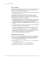
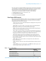
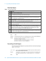
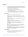
When accessing error messages using the SCPI (remote interface) error queue, the error numbers and the <error_description> portions of the error query response are displayed on the host terminal.
Characteristic
SCPI Remote Interface Error Queue
Capacity (#errors)
30
Overflow Handling
Linear, first-in/first-out.
Replaces newest error with: -350, Queue overflow
Viewing Entries
Use SCPI query SYSTem:ERRor[:NEXT]?
Clearing the Queue Power up
Send a *CLS command
Read last item in the queue
Unresolved Errors*
Re-reported after queue is cleared.
No Errors
When the queue is empty (every error in the queue has been read, or the queue is
cleared), the following message appears in the queue:
+0, "No error"
* Errors that still exist after clearing the error queue. For example, unlock.
Error Message File
A complete list of error messages is provided in the file errormessages.pdf, on the CD-ROM
supplied with your instrument. In the error message list, an explanation is generally
included with each error to further clarify its meaning. The error messages are listed
numerically. In cases where there are multiple listings for the same error number, the
messages are in alphabetical order.
Error Message Types
Events generate only one type of error. For example, an event that generates a query error
will not generate a device-specific, execution, or command error.
Query Errors (–499 to –400) indicate that the instrument’s output queue control has
detected a problem with the message exchange protocol described in IEEE 488.2, Chapter 6.
Errors in this class set the query error bit (bit 2) in the event status register (IEEE 488.2,
section 11.5.1). These errors correspond to message exchange protocol errors described in
IEEE 488.2, 6.5. In this case:
Either an attempt is being made to read data from the output queue when no output is
either present or pending, or
Agilent N8211A/N8212A Performance Upconverter Synthetic Instrument Module, 250 kHz to 20 / 40 GHz
23
1
Getting Started with Remote Operation
data in the output queue has been lost.
Device Specific Errors (–399 to –300, 201 to 703, and 800 to 810) indicate that a
device operation did not properly complete, possibly due to an abnormal hardware or
firmware condition. These codes are also used for self-test response errors. Errors in this
class set the device-specific error bit (bit 3) in the event status register (IEEE 488.2, section
11.5.1).
The <error_message> string for a positive error is not defined by SCPI. A positive error
indicates that the instrument detected an error within the GPIB system, within the
instrument’s firmware or hardware, during the transfer of block data, or during calibration.
Execution Errors (–299 to –200) indicate that an error has been detected by the
instrument’s execution control block. Errors in this class set the execution error bit (bit 4) in
the event status register (IEEE 488.2, section 11.5.1). In this case:
Either a <PROGRAM DATA> element following a header was evaluated by the device as
outside of its legal input range or is otherwise inconsistent with the device’s capabilities, or
a valid program message could not be properly executed due to some device condition.
Execution errors are reported after rounding and expression evaluation operations are
completed. Rounding a numeric data element, for example, is not reported as an execution
error.
Command Errors (–199 to –100) indicate that the instrument’s parser detected an
IEEE 488.2 syntax error. Errors in this class set the command error bit (bit 5) in the event
status register (IEEE 488.2, section 11.5.1). In this case:
• Either an IEEE 488.2 syntax error has been detected by the parser (a control-to-device
message was received that is in violation of the IEEE 488.2 standard. Possible violations
include a data element that violates device listening formats or whose type is
unacceptable to the device.), or
• An unrecognized header was received. These include incorrect device-specific headers
and incorrect or unimplemented IEEE 488.2 common commands.
24
Agilent N8211A/N8212A Performance Upconverter Synthetic Instrument Module, 250 kHz to 20 / 40 GHz
SCPI Programming Guide
2
Using the LAN Interface
“Using LAN" on page 26
“Connect LAN Cables and Turn On Power" on page 27
“Verify Connection with Synthetic Instrument Finder" on page 30
“Verifying LAN Functionality" on page 31
“Verifying LAN Functionality" on page 31
“Using VXI-11" on page 33
“Using Sockets LAN" on page 33
“Using Telnet LAN" on page 34
“Using FTP" on page 36
“Troubleshooting" on page 37
Agilent Technologies
25
2
Using the LAN Interface
Using LAN
The N8211A/N8212A is designed to connect with a 10Base-T LAN. Where auto-negotiation
is present, the N8211A/N8212A can connect to a 100Base-T LAN, but communicate at
10Base-T speeds. For more information refer to http://www.ieee.org.
The N8211A/N8212A can be remotely programmed via a 100Base-T LAN interface or
10Base-T LAN interface and LAN-connected computer using one of several LAN interface
protocols. The LAN allows instruments to be connected together and controlled by a
LAN-based computer. LAN and its associated interface operations are defined in the IEEE
802.2 standard. For more information refer to http://www.ieee.org.
The following sections contain information on selecting and connecting IO libraries and
LAN interface hardware that are required to remotely program the N8211A/N8212A via
LAN to a LAN-based computer and combining those choices with one of several possible
LAN interface protocols.
• “Connect LAN Cables and Turn On Power" on page 27
• “Verify Connection with Synthetic Instrument Finder" on page 30
• “Configuring for VXI-11" on page 33
The N8211A/N8212A supports the following LAN interface protocols:
• VXI-11 (See“Using VXI-11" on page 33)
• Sockets LAN (See“Using Sockets LAN" on page 33)
• Telephone Network (TELNET) (See “Using Telnet LAN" on page 34)
• File Transfer Protocol (FTP) (See “Using FTP" on page 36)
VXI-11 and sockets LAN are used for general programming using the LAN interface,
TELNET is used for interactive, one command at a time instrument control, and FTP is for
file transfer.
26
Agilent N8211A/N8212A Performance Upconverter Synthetic Instrument Module, 250 kHz to 20 / 40 GHz
2
Using the LAN Interface
Connect LAN Cables and Turn On Power
Before connecting to a LAN, verify your local policy by contacting the system administrator
in your Information Technology (IT) department and inquire about connecting instruments
to the LAN.
• If the network uses DHCP (Dynamic Host Configuration Protocol), an address is
assigned to the device automatically. If you need to know what the IP address is, it can
be determined using the Synthetic Instrument Finder. (Refer to “Verify Connection with
Synthetic Instrument Finder" on page 30.)
• If DHCP is not present, but the instrument is set to use DHCP (the default), the
instrument waits two minutes for its DHCP request to time out. When the
N8211A/N8212A is used in this situation, there is a time delay of approximately
three minutes between the time of when the N8211A/N8212A’s power is turned
on and when it is available for use.
• If the network does not use DHCP, you can use Auto IP or configure your LAN
settings manually. Although you can also manually configure LAN settings in a
network with DHCP, it is recommended that you do so with the assistance of your
system administrator.
• If the network uses Auto IP (does not use DHCP), the N8211A/N8212A acquires a
169.254.xxx.xxx address. (If you want to use a fixed address, refer to “How to Set a
Static IP Address" on page 41.)
NOTE
If you wish to communicate directly between the N8211A/N8212A and your PC without the
use of a LAN hub, you can connect directly to your PC using a crossover cable. (Refer to
“Connect to a LAN with a Cross-Over LAN Cable" on page 28.)
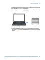
1 Connect a LAN cable from the LAN connector on your PC to an empty connector on your
internal local area network or LAN hub.
2 Connect a LAN cable from the LAN connector on the rear panel of the N8211A/N8212A
to an empty connector on your internal local area network or LAN hub.
Agilent N8211A/N8212A Performance Upconverter Synthetic Instrument Module, 250 kHz to 20 / 40 GHz
27
2
Using the LAN Interface
3 Turn on power to the N8211A/N8212A and wait until the LAN LED turns solid green;
this can take up to four minutes depending on whether the instrument is using DHCP or
Auto IP.
Connect to a LAN with a Cross-Over LAN Cable
You can connect the N8211A/N8212A directly to a PC using a crossover cable. To do this,
you should either choose to set IP addresses of the PC and N8211A/N8212A to differ only
in the last digit (example: PC’s IP: 1.1.1.1 and N8211A/N8212A’s IP: 1.1.1.2); or you can use
the DHCP feature or Auto-IP feature if your PC supports them. For more information go to
www.agilent.com, and search on the Connectivity Guide (E2094-90009) or use the Agilent
Connection Expert’s Help to see the Connection Guide.
28
Agilent N8211A/N8212A Performance Upconverter Synthetic Instrument Module, 250 kHz to 20 / 40 GHz
Using the LAN Interface
2
If you wish to communicate directly between the N8211A/N8212A and your PC without the
use of a LAN hub, you can connect directly to your PC.
1 Connect a cross-over LAN cable from the LAN connector on your PC to the LAN
connector on the rear panel of the N8211A/N8212A.
2 Turn on power to the PC.
3 Turn on power to the N8211A/N8212A and wait until the LAN LED turns solid green;
this can take up to four minutes depending on whether the instrument is using DHCP or
Auto IP.
Agilent N8211A/N8212A Performance Upconverter Synthetic Instrument Module, 250 kHz to 20 / 40 GHz
29
2
Using the LAN Interface
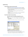
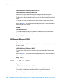
Verify Connection with Synthetic Instrument Finder
Agilent supplies a program named the Synthetic Instrument Finder that enables connection
between a PC and instruments that are connected on a LAN (Local Area Network).
1 From the Windows Desktop, click Start > Programs > Agilent SI Tools > Synthetic
Instrument Finder.
The Synthetic Instrument Finder will open and look similar to the following.
2 Select an instrument, from the left-hand pane of the Synthetic Instrument Finder, and
right-click on it.
3 Select Open Webpage and a Web page should appear that allows viewing and
modifying settings for instruments on the network will open.
30
Agilent N8211A/N8212A Performance Upconverter Synthetic Instrument Module, 250 kHz to 20 / 40 GHz
2
Using the LAN Interface
If this Web page does not open or you experience an error, refer to “Troubleshooting" on
page 37.
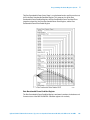
Verifying LAN Functionality
Verify the communications link between the computer and the N8211A/N8212A remote file
server using the ping utility. Compare your ping response to those described in Table 1 on
page 32.
From a UNIX® workstation, type (UNIX
™ is a registered trademark of the Open Group):
ping <hostname or IP address> 64 10
where <hostname or IP address> is your instrument’s name or IP address, 64 is the
packet size, and 10 is the number of packets transmitted. Type man ping at the UNIX
prompt for details on the ping command.
From the MS-DOS® Command Prompt or Windows environment, type:
ping -n 10 <hostname or IP address>
where <hostname or IP address> is your instrument’s name or IP address and 10 is
the number of echo requests. Type ping at the command prompt for details on the ping
command.
Agilent N8211A/N8212A Performance Upconverter Synthetic Instrument Module, 250 kHz to 20 / 40 GHz
31
2
Using the LAN Interface
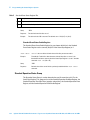
Table 1
Ping Responses
Normal Response for
UNIX
A total of 9 or 10 packets received with a minimal average
round-trip time. The minimal average will be different from
network to network. LAN traffic will cause the round-trip to vary
widely.
Normal Response for
DOS or Windows
A total of 9 or 10 packets received if 10 echo requests were
specified.
If you have problems, refer to “Troubleshooting" on page 37.
32
Agilent N8211A/N8212A Performance Upconverter Synthetic Instrument Module, 250 kHz to 20 / 40 GHz
2
Using the LAN Interface
Using VXI-11
The N8211A/N8212A supports the LAN interface protocol described in the VXI-11
standard. VXI-11 is an instrument control protocol based on Open Network
Computing/Remote Procedure Call (ONC/RPC) interfaces running over TCP/IP. It is
intended to provide GPIB capabilities such as SRQ (Service Request), status byte reading,
and DCAS (Device Clear State) over a LAN interface. This protocol is a good choice for
migrating from GPIB to LAN as it has full Agilent VISA/SICL support.
It is recommended that the VXI-11 protocol or IVI COM DRIVER be used for instrument
communication over the LAN interface.
Configuring for VXI-11
The Agilent IO library has a program, IO Config, that is used to setup the
computer/N8211A/N8212A interface for the VXI-11 protocol. Download the latest version
of the Agilent IO library from the Agilent website.
Use the IO Config program to configure the LAN client. Once the computer is configured for
a LAN client, you can use the VXI-11 protocol and the VISA library to send SCPI commands
to the N8211A/N8212A over the LAN interface. Example programs for this protocol are
included in “LAN Programming Interface Examples" on page 55 of this guide.
Using Sockets LAN
Users with Windows XP and newer operating systems can use this section to better
understand how to use the N8211A/N8212A with port settings. For more information, refer
to the help software of the IO libraries being used.
Sockets LAN is a method used to communicate with the N8211A/N8212A over the LAN
interface using the Transmission Control Protocol/Internet Protocol (TCP/IP). A socket is a
fundamental technology used for computer networking and allows applications to
communicate using standard mechanisms built into network hardware and operating
systems. The method accesses a port on the N8211A/N8212A from which bidirectional
communication with a network computer can be established.
Sockets LAN can be described as an internet address that combines Internet Protocol (IP)
with a device port number and represents a single connection between two pieces of
software. The socket can be accessed using code libraries packaged with the computer
operating system. Two common versions of socket libraries are the Berkeley Sockets
Library for UNIX systems and Winsock for Microsoft operating systems.
Your N8211A/N8212A implements a sockets Applications Programming Interface (API)
that is compatible with Berkeley socket for UNIX systems, and Winsock for Microsoft
systems. The N8211A/N8212A is also compatible with other standard sockets APIs. The
N8211A/N8212A can be controlled using SCPI commands that are output to a socket
connection established in your program.
Agilent N8211A/N8212A Performance Upconverter Synthetic Instrument Module, 250 kHz to 20 / 40 GHz
33
2
Using the LAN Interface
Before you can use sockets LAN, you must select the N8211A/N8212A’s sockets port
number to use:
• Standard mode. Available on port 5025. Use this port for simple programming.
• TELNET mode. The telnet SCPI service is available on port 5023.
An example using sockets LAN is given in “LAN Programming Interface Examples" on
page 55 of this programming guide.
Using Telnet LAN
Telnet provides a means of communicating with the N8211A/N8212A over the LAN. The
Telnet client, run on a LAN connected computer, will create a login session on the
N8211A/N8212A. A connection, established between computer and N8211A/N8212A,
generates a user interface display screen with SCPI> prompts on the command line.
Using the Telnet protocol to send commands to the N8211A/N8212A is similar to
communicating with an instrument over GPIB. You establish a connection with the
N8211A/N8212A and then send or receive information using SCPI commands.
Communication is interactive: one command at a time.
Windows XP operating systems and newer can use this section to better understand how
to use the N8211A/N8212A with port settings.
The following telnet LAN connections are discussed:
• “Using Telnet and MS-DOS Command Prompt" on page 34
• “The Standard UNIX Telnet Command" on page 35
A Telnet example is provided in “UNIX Telnet Example" on page 35.
Using Telnet and MS-DOS Command Prompt
1 On your PC, click Start > All Programs > Accessories > Command Prompt.
2 At the command prompt, type in telnet.
3 Press Enter. The Telnet display screen will be displayed.
4 Click on the Connect menu then select Remote System.
5 Enter the hostname, port number, and TermType then click Connect.
• Host Name−IP address or hostname
• Port−5023
• Term Type−vt100
6 At the SCPI> prompt, enter SCPI commands.
7 To signal device clear, press Ctrl-C on your keyboard.
8 Type exit at the command prompt to end the Telnet session.
34
Agilent N8211A/N8212A Performance Upconverter Synthetic Instrument Module, 250 kHz to 20 / 40 GHz
2
Using the LAN Interface
The Standard UNIX Telnet Command
Synopsis
telnet [host [port]]
Description
This command is used to communicate with another host using the Telnet protocol. When
the command telnet is invoked with host or port arguments, a connection is opened
to the host, and input is sent from the user to the host.
Options and Parameters
The command telnet operates in character-at-a-time or line-by-line mode. In line-by-line
mode, typed text is echoed to the screen. When the line is completed (by pressing the Enter
key), the text line is sent to host. In character-at-a-time mode, text is echoed to the screen
and sent to host as it is typed. At the UNIX prompt, type man telnet to view the options
and parameters available with the telnet command.
If your Telnet connection is in line-by-line mode, there is no local echo. This means you
cannot see the characters you are typing until you press the Enter key. To remedy this,
change your Telnet connection to character-by-character mode. Escape out of Telnet, and at
the telnet> prompt, type mode char. If this does not work, consult your Telnet
program's documentation.
UNIX Telnet Example
1 To connect to the instrument with host name myInstrument and port number 5023,
enter the following command on the command line: telnet myInstrument 5023.
2 When you connect to the N8211A/N8212A, the UNIX window will display a welcome
message and a SCPI command prompt. The instrument is now ready to accept your SCPI
commands. As you type SCPI commands, query results appear on the next line.
3 When you are finished, break the Telnet connection using an escape character. For
example, Ctrl-],where the control key and the “]” are pressed at the same time.
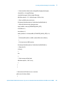
The following example shows Telnet commands:
$ telnet myinstrument 5023
Trying....
Connected to N8211A/N8212A
Escape character is ‘^]’.
Agilent Technologies, N821xA SN-US00000001
IP: 199.198.197.201 (Note: Do not confuse this address with the instrument address.)
SCPI>
Agilent N8211A/N8212A Performance Upconverter Synthetic Instrument Module, 250 kHz to 20 / 40 GHz
35
2
Using the LAN Interface
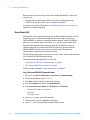
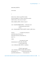
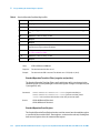
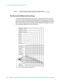
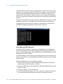
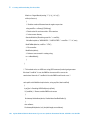
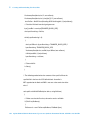
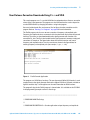
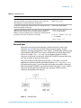
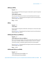
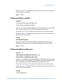
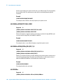
Using FTP
FTP allows users to transfer files between the N8211A/N8212A and any computer
connected to the LAN. For example, you can use FTP to download instrument screen
images to a computer. When logged onto the N8211A/N8212A with the FTP command, the
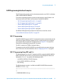
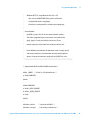
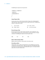
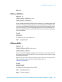
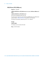
N8211A/N8212A’s file structure can be accessed. Figure 2 shows the FTP interface and
lists the directories in the N8211A/N8212A’s user level directory.
File access is limited to the N8211A/N8212A’s /user directory.
Figure 2
FTP Screen
The following steps outline a sample FTP session from the MS-DOS Command Prompt:
1 On the PC click Start > Programs > Command Prompt.
2 At the command prompt enter:
ftp < IP address > or < hostname >
3 At the user name prompt, press Enter.
4 At the password prompt, press Enter.
You are now in the N8211A/N8212A’s user directory.
5 Type quit or bye to end your FTP session.
6 Type exit to end the command prompt session.
36
Agilent N8211A/N8212A Performance Upconverter Synthetic Instrument Module, 250 kHz to 20 / 40 GHz
2
Using the LAN Interface
Troubleshooting
Alternative Ways to Verify Connectivity to the PC
In addition to using “Verify Connection with Synthetic Instrument Finder" on page 30,
connectivity can be verified between the N8211A/N8212A and the PC with the following:
• Verify that the LAN LED on the N8211A/N8212A’s front panel is green or blinking green.
This indicates a good connection.
If the LED is Red, there is a problem with your LAN connection. This takes
approximately 60 seconds.
• Verify that the LAN LED on the N8211A/N8212A’s rear panel (next to the LAN port) is
solid green.
• Ping the N8211A/N8212A from the PC. Refer to Table 1 on page 32.
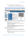
How to Use the Synthetic Instrument Finder
Agilent supplies a program named the Synthetic Instrument Finder that enables
connection between a PC and instruments that are connected on a LAN (Local Area
Network).
1 From the Windows Desktop, click Start > All Programs > Agilent SI Tools > Synthetic
Instrument Finder.
The Synthetic Instrument Finder should appear and look similar to the following.
The Synthetic Instrument Finder window is divided into two main sections:
• right pane contains information specific to the instrument highlighted in the left pane.
• left pane contains a list of equipment available on your LAN for connection.
Agilent N8211A/N8212A Performance Upconverter Synthetic Instrument Module, 250 kHz to 20 / 40 GHz
37
2
Using the LAN Interface
Right-Pane Functions
Send Settings Sends the current instrument settings to the N8211A/N8212A. Use this
function if you modified the settings in Instrument Finder.
5 Second Identify
Flashes the LAN LED for five seconds.
Turn On Ident LED When On, the LAN LED continuously flashes on and off. Once the
Turn On Ident LED button is pressed, the button name changes to Turn Off Ident LED.
Refresh List
Updates the device list.
Continuous Refresh
Updates the device list every one minute.
Add Device Manually Allows you to add a device for connection. Use this feature only if
your instrument does not appear in the Devices list.
a Click Add Device Manually. The Devices area will display a new listing titled
“Unknown”.
b In the Manual settings area, enter in the MAC address, serial number, and model
number of the device.
c In the LAN settings area, enter in the information for the new device. (Make sure
that you scroll down the list to get to the editable settings area.)
d Click Send Settings to enter this information in the Devices area.
e Double-click the new listing to open the webpage, or right-click and select Open
using Synthetic GUI to use the virtual interface.
Left-Pane Functions
In the left pane, right-click on the N8211A/N8212A and the following menu will appear.
Interactive IO Opens the Agilent Interactive IO application which allows SCPI
commands to be sent to the instrument. (The Interactive IO option is only available if the
Agilent Connection Expert has been installed on the PC.)
Open Webpage Opens the Web page associated with the currently selected instrument.
From this Web page, settings for the instrument can be viewed and modified.
38
Agilent N8211A/N8212A Performance Upconverter Synthetic Instrument Module, 250 kHz to 20 / 40 GHz
2
Using the LAN Interface
Tip:
There are two other ways to access the device’s Web page:
• By double-clicking on the Device listing in the Synthetic Instrument Finder.
• By typing in the device’s hostname or IP address in your Internet browser.
Open using Synthetic GUI
Opens the Synthetic Instrument GUI.
Copy VISA Address to Clipboard (IP Address)
clipboard for use in other applications.
Copies the VISA IP address to the
Copy VISA Address to Clipboard (Hostname) Copies the VISA hostname to the
clipboard for use in other applications. It is recommended that you use this address on
networks with DHCP and DNS network capability.
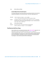
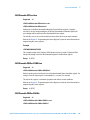
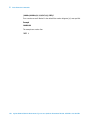
How to Reset the LAN Configuration
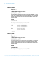
On the instrument front panel, near the power switch, is a recessed button labeled
“RESET”. This button enables you to place the LAN configuration of the instrument into a
known state.
When this button is pressed (a straightened paper clip will do the job) the following settings
are made and the system reboots.
• Subnet Mask is set to 255.255.0.0
Agilent N8211A/N8212A Performance Upconverter Synthetic Instrument Module, 250 kHz to 20 / 40 GHz
39
2
Using the LAN Interface
• DHCP is set to on
• Auto IP is set to on
NOTE
If DHCP and Auto IP are set to off, the IP address will be set to 192.168.EE.FF, where EE and
FF are the last two parts of the MAC address (AA.BB.CC.DD.EE.FF). This is designed to
prevent multiple instruments from using the same default IP address (refer to the
instrument label).
If you had manually configured LAN settings before, you may have to reconfigure your
instrument to reset DHCP and Auto IP to OFF. Refer to “How to Set a Static IP Address" on
page 41.
• The instrument hostname is set to A-N82XXA-NNNNN, where N82XXA is the
instrument model number (such as N8211A) and NNNNN represents the last five digits
of the instrument serial number.
If the instrument is in an environment with a DHCP server, it is assigned an IP address
through DHCP. The IP address can be found by using the instrument hostname as the URL
in a web browser.
Without DHCP, the instrument will use Auto IP and acquire a 169.254.X.X address. If no
DHCP is present, but the instrument is set to use DHCP (the default), the instrument will
wait two minutes for its DHCP request to time out. In this case, there is a time delay of
approximately three minutes between when the instrument is powered on and when it is
usable.
Recessed
LAN RST
Button
40
Agilent N8211A/N8212A Performance Upconverter Synthetic Instrument Module, 250 kHz to 20 / 40 GHz
2
Using the LAN Interface
How to Set a Static IP Address
The DHCP server automates the process of setting up the IP addresses on your network by
default. When the N8211A/N8212A is turned on, it searches for a DHCP server on the
network and selects a “dynamic IP address”. Each time the N8211A/N8212A is rebooted,
the N8211A/N8212A may get a different IP address. To set the N8211A/N8212A to a static
IP address, rather than allowing the DHCP server to select an auto IP address:
1 Using either a Web page or Synthetic Instrument Finder, assign a N8211A/N8212A
instrument IP address that will work with your computer. Refer to “How to Use the
Synthetic Instrument Finder" on page 37.
F
NOTE
For a company wide network, your system administrator will have to assign an IP address
that is compatible with your PC. If you have a private LAN network or a direct connection
from your PC to the instrument, you can assign the IP address.
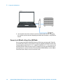
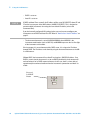
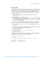
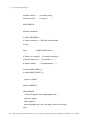
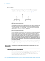
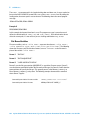
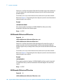
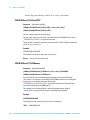
2 Connect the N8211A/N8212A in one of the following two configurations:
• Connect a LAN cable from the LAN connector on your PC to an empty connector
on your internal local area network or LAN hub. Connect a LAN cable from the
LAN connector on the rear panel of the N8211A/N8212A to an empty connector
on your internal local area network or LAN hub.
Figure 3
Connecting the PC LAN cable to a company/private LAN to the instrument LAN
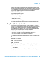
• Connect a cross-over cable from the LAN connector on your PC to the LAN
connector on the rear panel of the N8211A/N8212A.
Agilent N8211A/N8212A Performance Upconverter Synthetic Instrument Module, 250 kHz to 20 / 40 GHz
41
2
Using the LAN Interface
Figure 4
Connecting the PC LAN cable to the instrument LAN (cross-over cable)
3 Turn on power to the PC.
4 Turn on power to the N8211A/N8212A and wait until the LAN LED turns solid green;
this takes about 60 seconds.
5 From the Windows Desktop, click Start > All Programs > Agilent SI Tools > Synthetic
Instrument Finder.
The following Synthetic Instrument Finder dialog box should appear.
6 Select the N8211A/N8212A listed in the Agilent Synthetic Instrument Finder dialog box
to access the N8211A/N8212A Web page.
42
Agilent N8211A/N8212A Performance Upconverter Synthetic Instrument Module, 250 kHz to 20 / 40 GHz
Using the LAN Interface
2
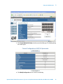
7 Click View & Modify LAN Config in the left-pane of the Web page. The following dialog
box should appear.
8 Click Modify Configuration to access the Password dialog.
Agilent N8211A/N8212A Performance Upconverter Synthetic Instrument Module, 250 kHz to 20 / 40 GHz
43
2
Using the LAN Interface
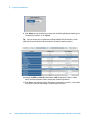
9 Click Submit (accept the default password) and the following dialog box should appear.
The default password is set to “agilent”.
Tip: You can change the password from the View & Modify LAN Connections. (Scroll
down the Parameter column until you locate the Change Password parameter.)
10 Change the DHCP and Auto IP radio-buttons to Off. Change the IP address, Subnet
Mask, and Default Gateway values to meet your network requirements.
11 Click Save to save the new settings. Parameters marked with an asterisk (*) also require
that you click "Renew LAN settings" before changes take effect.
44
Agilent N8211A/N8212A Performance Upconverter Synthetic Instrument Module, 250 kHz to 20 / 40 GHz
2
Using the LAN Interface
How to Troubleshoot Connectivity Problems on the Network
The Synthetic Instrument Finder program is used to find instruments on a network when
the N8211A/N8212A is connected through a company LAN router or cross-over cable.
There are three possible configurations:
• connecting the PC through a company wide site LAN connection to the
N8211A/N8212A
• connecting the PC to the same private LAN network as the instrument
• connecting the PC directly to the instrument using a cross-over cable - this would
typically be used for troubleshooting and is not normally used to control an instrument
directly
How to Determine a PCs Configuration Settings
From a DOS Window
1 From the Windows Desktop, click Start > Run.
2 At the Open: prompt, type CMD and press Enter to open a DOS window.
3 At the command prompt, type ipconfig/all to display the PCs network connection
details.
Or,
From the PCs Control Panel
1 From the Windows Desktop, click Start > Settings > Control Panel > Network and
Internet Connections.
2 From the Network and Internet Connections window, double-click the Local Area
Connection.
3 In the Local Area Connection Status dialog, click the Support tab and click Details to
display the PCs Network Connection Details.
The Network Connection Details include:
• Physical Address
• DHCP status, enabled or disabled (displayed when using the DOS window ipconfig
command only)
• Auto configuration enabled or disabled (displayed when using the DOS window ipconfig
command only)
• IP Address
• Subnet Mask
• Default Gateway
• DHCP Server Address
Agilent N8211A/N8212A Performance Upconverter Synthetic Instrument Module, 250 kHz to 20 / 40 GHz
45
2
Using the LAN Interface
• Lease Obtained
• Lease Expired
• Primary WINS Servers
• Secondary WINS Servers
If the Instrument was Unable to Join the LAN
or
If the LAN LED is Red
Symptom
Possible Causes
Possible Solutions
The instrument is not connected to a LAN.
If connecting the instrument to a switch or hub, verify
that the instrument is connected with a standard LAN
cable.
An incorrect LAN cable is being used.
• If connecting the instrument directly to a PC, verify
that the instrument is connected with a cross-over
cable.
• If connecting the instrument to a switch or hub,
verify that the instrument is connected with a
standard LAN cable.
The device’s LAN port is not active.
Connect the instrument to a known working LAN
port.
The device is configured to use DHCP, but no DHCP
server is available.
• Disable DHCP. Refer to “How to Set a Static IP
Address" on page 41.
• Connect the device to a LAN that uses a DHCP
server.
The instrument is configured to use a duplicate static
IP address.
• Make sure that no other device is using the same
IP address as your instrument.
• Configure your instrument to use a different IP
address. Refer to “How to Set a Static IP
Address" on page 41.
If the Instrument’s IP Address or Hostname Cannot be Found with Ping
46
Possible Causes
Possible Solutions
The instrument was unable to join the LAN.
See “If the Instrument was Unable to Join the
LAN" on page 46.
The instrument’s LAN settings are incorrect.
Verify that the instrument’s settings are appropriate
for your LAN.
Agilent N8211A/N8212A Performance Upconverter Synthetic Instrument Module, 250 kHz to 20 / 40 GHz
2
Using the LAN Interface
Possible Causes
Possible Solutions
A firewall is preventing communication between your Make sure that your firewall settings allow
PC and your instrument.
communication between your PC and other devices.
The instrument is using Auto-IP (That is, the
instrument assigned itself a 169.254.x.x IP address)
and your PC is not using Auto IP (That is, PC does not
have a 169.254.x.x IP address.)
• Disable Auto-IP on the instrument.
• Configure your PC to use Auto-IP.
Error Messages
• If error messages appear, check the command
syntax before continuing with troubleshooting. If
the syntax is correct, resolve the error messages
using your network documentation or by
consulting your network administrator.
• If an unknown host error appears, try using the IP
address instead of the hostname. Also, verify that
the hostname and IP address for the
N8211A/N8212A have been registered by your IT
administrator.
• Check that the hostname and IP address are
correctly entered in the node names database. To
do this, enter the nslookup <hostname>
command from the command prompt.
No Response
• No packets were received. Check that the typed
•
•
•
•
Intermittent Response
address or hostname matches the IP address or
hostname assigned to the N8211A/N8212A. Refer
to “How to Set a Static IP Address" on page 41.
Ping each node along the route between your
workstation and the N8211A/N8212A, starting
with your workstation. If a node does not respond,
contact your IT administrator.
If the N8211A/N8212A still does not respond to a
ping, you should suspect a hardware problem.
Check the N8211A/N8212A connector lights
Verify the hostname is not being used with DHCP
addressing
If you received less packets back then you sent, there
may be a problem with the network. In networks with
switches and bridges, the first few pings may be lost
until these devices “learn” the location of hosts. Also,
because the number of packets received depends on
your network traffic and integrity, the number might
be different for your network. Problems of this nature
are best resolved by your IT department.
Agilent N8211A/N8212A Performance Upconverter Synthetic Instrument Module, 250 kHz to 20 / 40 GHz
47
2
Using the LAN Interface
If the Instrument is Not Found by the Synthetic Instrument Finder
Possible Causes
Possible Solutions
The instrument was unable to join the LAN.
See “If the Instrument was Unable to Join the
LAN" on page 46.
The instrument and PC are on different
switches/hubs and different subnets.
• Put the instrument on the same switch or hub as
your PC.
• If the instrument is using DHCP, make sure that the
instrument and the PC are put on the same subnet.
• If the instrument is using a static IP address, make
sure that the instrument IP address and subnet
mask put the instrument on the same subnet as
your PC.
If the Instrument’s Hostname and PC Cannot Communicate
Possible Causes
Possible Solutions
No DNS server is available.
Communicate with the instrument using the
instrument’s IP address.
The DNS server has not been updated.
Wait several minutes.
The PC cannot communicate with the device over
LAN.
See “If the Instrument’s IP Address or Hostname
Cannot be Found with Ping" on page 46.
If the Instrument Web Page is Not Visible
48
Possible Causes
Possible Solutions
• The instrument has not yet joined the LAN.
• The instrument is unable to join the LAN.
See “If the LAN LED is Red" on page 46.
Your PC cannot communicate with the device over
your LAN.
See “If the Instrument was Unable to Join the
LAN" on page 46.
You are attempting to use the device’s hostname and
the hostname is not working.
See “If the Instrument’s Hostname and PC Cannot
Communicate" on page 48.
Your browser is configured to use a proxy, and the
proxy does not allow communication with
instruments on the LAN.
Disable or reconfigure the proxy settings. Open
Internet Explorer and select Tools > Internet Options
> Connections > LAN Settings…
Agilent N8211A/N8212A Performance Upconverter Synthetic Instrument Module, 250 kHz to 20 / 40 GHz
Using the LAN Interface
2
If the Software Driver Will Not Open the Connection
Possible Causes
Possible Solutions
Your PC cannot communicate with the device over
your LAN.
See “If the Instrument’s IP Address or Hostname
Cannot be Found with Ping" on page 46.
Someone else is currently connected to the
instrument.
Make sure that no one else is connected to the
instrument.
Agilent N8211A/N8212A Performance Upconverter Synthetic Instrument Module, 250 kHz to 20 / 40 GHz
49
2
50
Using the LAN Interface
Agilent N8211A/N8212A Performance Upconverter Synthetic Instrument Module, 250 kHz to 20 / 40 GHz
SCPI Programming Guide
3
Programming Examples
“Using the Programming Interface Examples" on page 52
“LAN Programming Interface Examples" on page 55
Agilent Technologies
51
3
Programming Examples
Using the Programming Interface Examples
The programming examples for remote control of the N8211A/N8212A use the GPIB, LAN,
and RS-232 interfaces and demonstrate instrument control using different IO libraries and
programming languages. Many of the example programs in this chapter are interactive; the
user will be prompted to perform certain actions or verify N8211A/N8212A operation or
functionality. Example programs are written in the following languages:
HP Basic
C#
C/C++
Microsoft Visual Basic 6.0
Java
MATLAB
Perl
These example programs are also available on the N8211A/N8212A Documentation
CD-ROM, enabling you to cut and paste the examples into a text editor.
Programming Examples Development Environment
The C/C++ examples were written using an IBM-compatible personal computer (PC),
configured as follows:
• Pentium® processor (Pentium is a registered trademark of Intel Corporation.)
• Windows NT 4.0 operating system or later
• MS Visual Studio
The HP Basic examples were run on a UNIX 700 series workstation.
Running C++ Programs
When using Microsoft Visual C++ 6.0 to run the example programs, include the following
files in your project.
When using the VISA library:
• add the visa32.lib file to the Resource Files
• add the visa.h file to the Header Files
When using the NI-488.2 library:
• add the GPIB-32.OBJ file to the Resource Files
• add the windows.h file to the Header Files
• add the Deci-32.h file to the Header Files
For information on the NI-488.2 library and file requirements refer to the National
Instrument website. For information on the VISA library see the Agilent website or National
Instrument’s website.
52
Agilent N8211A/N8212A Performance Upconverter Synthetic Instrument Module, 250 kHz to 20 / 40 GHz
3
Programming Examples
C/C++ Examples
• “VXI-11 Programming Using SICL and C++" on page 55
• “VXI-11 Programming Using VISA and C++" on page 58
• “Sockets LAN Programming Using Java" on page 91
Running C# Examples
To run the example program State_Files.cs in “Save and Recall Programming Example
Using VISA and C#" on page 133, you must have the .NET framework installed on your
computer. You must also have the Agilent IO Libraries installed on your computer. The .NET
framework can be downloaded from the Microsoft website. For more information on
running C# programs using .NET framework, see Chapter 5.
Running Basic Examples
The BASIC programming interface examples provided in this chapter use either HP Basic or
Visual Basic 6.0 languages.
Visual Basic 6.0 Programming Examples
To run the example programs written in Visual Basic 6.0 you must include references to the
IO Libraries. For more information on VISA and IO libraries, refer to the Agilent VISA User’s
Manual, available on Agilent’s website: http://www.agilent.com. In the Visual Basic IDE
(Integrated Development Environment) go to Project–References and place a check mark
on the following references:
• Agilent VISA COM Resource Manager 1.0
• VISA COM 1.0 Type Library
If you want to use VISA functions such as viWrite, then you must add the visa32.bas
module to your Visual Basic project.
The N8211A/N8212A’s VXI-11 SCPI service must be on before you can run the Download
Visual Basic 6.0 programming example.
You can start a new Standard EXE project and add the required references. Once the
required references are included, you can copy the example programs into your project and
add a command button to Form1 that will call the program.
The example Visual Basic 6.0 programs are available on the N8211A/N8212A
Documentation CD-ROM, enabling you to cut and paste the examples into your project.
Running Java Examples
The Java program “Sockets LAN Programming Using Java" on page 91, connects to the
N8211A/N8212A via sockets LAN. This program requires Java version 1.1 or later be
installed on your PC.
Agilent N8211A/N8212A Performance Upconverter Synthetic Instrument Module, 250 kHz to 20 / 40 GHz
53
3
Programming Examples
Running Perl Examples
The Perl example “Sockets LAN Programming Using PERL" on page 94, uses PERL script to
control the N8211A/N8212A over the sockets LAN interface.
54
Agilent N8211A/N8212A Performance Upconverter Synthetic Instrument Module, 250 kHz to 20 / 40 GHz
3
Programming Examples
LAN Programming Interface Examples
The LAN programming examples in this section demonstrate the use of VXI-11 and Sockets
LAN to control the N8211A/N8212A.
To use these programming examples you must change references to the IP address and
hostname to match the IP address and hostname of your N8211A/N8212A.
• “VXI-11 Programming Using SICL and C++" on page 55
• “VXI-11 Programming Using VISA and C++" on page 58
• “Sockets LAN Programming and C" on page 60
• “Sockets LAN Programming Using Java" on page 91
• “Sockets LAN Programming Using PERL" on page 94
For additional LAN programming examples that work with user-data files, refer to:
“Save and Recall Instrument State Files" on page 133
VXI-11 Programming
The N8211A/N8212A supports the VXI-11 standard for instrument communication over the
LAN interface. Agilent IO Libraries support the VXI-11 standard and must be installed on
your computer before using the VXI-11 protocol. Refer to“Using VXI-11" on page 33 for
information on configuring and using the VXI-11 protocol.
The VXI-11 examples use TCPIP0 as the board address.
To communicate with the N8211A/N8212A over the LAN interface you must enable the
VXI-11 SCPI service. For more information, refer to “Configuring for VXI-11" on page 33.
VXI-11 Programming Using SICL and C++
The following program uses the VXI-11 protocol and SICL to control the N8211A/N8212A.
Before running this code, you must set up the interface using the Agilent IO Libraries IO
Config utility. vxisicl.cpp performs the following functions:
• sets N8211A/N8212A to 1 GHz CW frequency
• queries N8211A/N8212A for an ID string
• error checking
The following program example is available on the N8211A/N8212A Documentation
CD-ROM as vxisicl.cpp.
//****************************************************************************************
//
// PROGRAM NAME:vxisicl.cpp
Agilent N8211A/N8212A Performance Upconverter Synthetic Instrument Module, 250 kHz to 20 / 40 GHz
55
3
Programming Examples
//
// PROGRAM DESCRIPTION:Sample test program using SICL and the VXI-11 protocol
//
// NOTE: You must have the Agilent IO Libraries installed to run this program.
//
// This example uses the VXI-11 protocol to set the N8211A/N8212A for a 1 gHz CW
// frequency. The N8211A/N8212A is queried for operation complete and then queried
// for its ID string. The frequency and ID string are then printed to the display.
//
// IMPORTANT: Enter in your N8211A/N8212As hostname in the instrumentName
declaration
// where the "xxxxx" appears.
//
//****************************************************************************************
#include "stdafx.h"
#include <sicl.h>
#include <stdlib.h>
#include <stdio.h>
int main(int argc, char* argv[])
{
INST id;
int opcResponse;
// Device session id
// Variable for response flag
char instrumentName[] = "xxxxx"; // Put your instrument's hostname here
char instNameBuf[256];// Variable to hold instrument name
char buf[256];// Variable for id string
ionerror(I_ERROR_EXIT);// Register SICL error handler
56
Agilent N8211A/N8212A Performance Upconverter Synthetic Instrument Module, 250 kHz to 20 / 40 GHz
Programming Examples
3
// Open SICL instrument handle using VXI-11 protocol
sprintf(instNameBuf, "lan[%s]:inst0", instrumentName);
id = iopen(instNameBuf);// Open instrument session
itimeout(id, 1000);// Set 1 second timeout for operations
printf("Setting frequency to 1 Ghz...\n");
iprintf(id, "freq 1 GHz\n");// Set frequency to 1 GHz
printf("Waiting for source to settle...\n");
iprintf(id, "*opc?\n");// Query for operation complete
iscanf(id, "%d", &opcResponse); // Operation complete flag
if (opcResponse != 1)// If operation fails, prompt user
{
printf("Bad response to 'OPC?'\n");
iclose(id);
exit(1);
}
iprintf(id, "FREQ?\n");// Query the frequency
iscanf(id, "%t", &buf);// Read the N8211A/N8212A frequency
printf("\n");// Print the frequency to the display
printf("Frequency of N8211A/N8212A is %s\n", buf);
ipromptf(id, "*IDN?\n", "%t", buf);// Query for id string
printf("Instrument ID: %s\n", buf);// Print id string to display
iclose(id);// Close the session
return 0;
}
Agilent N8211A/N8212A Performance Upconverter Synthetic Instrument Module, 250 kHz to 20 / 40 GHz
57
3
Programming Examples
VXI-11 Programming Using VISA and C++
The following program uses the VXI-11 protocol and the VISA library to control the
N8211A/N8212A. The N8211A/N8212A is set to a –5 dBm power level and queried for its
ID string. Before running this code, you must set up the interface using the Agilent IO
Libraries IO Config utility. vxivisa.cpp performs the following functions:
• sets N8211A/N8212A to a –5 dBm power level
• queries N8211A/N8212A for an ID string
• error checking
The following program example is available on the N8211A/N8212A documentation
CD-ROM as vxivisa.cpp.
//****************************************************************************************
// PROGRAM FILE NAME:vxivisa.cpp
// Sample test program using the VISA libraries and the VXI-11 protocol
//
// NOTE: You must have the Agilent Libraries installed on your computer to run
// this program
//
// PROGRAM DESCRIPTION:This example uses the VXI-11 protocol and VISA to query
// the N8211A/N8212A for its ID string. The ID string is then printed to the
// screen. Next the N8211A/N8212A is set for a -5 dBm power level and then
// queried for the power level. The power level is printed to the screen.
//
// IMPORTANT: Set up the LAN Client using the IO Config utility
//
//****************************************************************************************
#include <visa.h>
#include <stdio.h>
#include "StdAfx.h"
#include <stdlib.h>
#include <conio.h>
58
Agilent N8211A/N8212A Performance Upconverter Synthetic Instrument Module, 250 kHz to 20 / 40 GHz
Programming Examples
3
#define MAX_COUNT 200
int main (void)
{
ViStatus status;// Declares a type ViStatus variable
ViSession defaultRM, instr;// Declares a type ViSession variable
ViUInt32 retCount;// Return count for string I/O
ViChar buffer[MAX_COUNT];// Buffer for string I/O
status = viOpenDefaultRM(&defaultRM); // Initialize the system
// Open communication with Serial
// Port 2
status = viOpen(defaultRM, "TPCIP0::19::INSTR", VI_NULL, VI_NULL, &instr);
if(status){
// If problems then prompt user
printf("Could not open ViSession!\n");
printf("Check instruments and connections\n");
printf("\n");
exit(0);}
// Set timeout for 5 seconds
viSetAttribute(instr, VI_ATTR_TMO_VALUE, 5000);
// Ask for sig gen ID string
status = viWrite(instr, (ViBuf)"*IDN?\n", 6, &retCount);
// Read the sig gen response
status = viRead(instr, (ViBuf)buffer, MAX_COUNT, &retCount);
buffer[retCount]= '\0';
printf("N8211A/N8212A ID = ");
// Indicate the end of the string
// Print header for ID
Agilent N8211A/N8212A Performance Upconverter Synthetic Instrument Module, 250 kHz to 20 / 40 GHz
59
3
Programming Examples
printf(buffer);
// Print the ID string
printf("\n");
// Print carriage return
// Flush the read buffer
// Set sig gen power to -5dbm
status = viWrite(instr, (ViBuf)"POW:AMPL -5dbm\n", 15, &retCount);
// Query the power level
status = viWrite(instr, (ViBuf)"POW?\n",5,&retCount);
// Read the power level
status = viRead(instr, (ViBuf)buffer, MAX_COUNT, &retCount);
buffer[retCount]= '\0';
// Indicate the end of the string
printf("Power level = ");
// Print header to the screen
printf(buffer);
// Print the queried power level
printf("\n");
status = viClose(instr);
// Close down the system
status = viClose(defaultRM);
return 0;
}
Sockets LAN Programming and C
The program listing shown in “Queries for Lan Using Sockets" on page 63 consists of two
files; lanio.c and getopt.c. The lanio.c file has two main functions; int main() and an
int main1().
The int main() function allows communication with the N8211A/N8212A interactively
from the command line. The program reads the N8211A/N8212A's hostname from the
command line, followed by the SCPI command. It then opens a socket to the
N8211A/N8212A, using port 5025, and sends the command. If the command appears to be
a query, the program queries the N8211A/N8212A for a response, and prints the response.
The int main1(), after renaming to int main(), will output a sequence of commands
to the N8211A/N8212A. You can use the format as a template and then add your own code.
This program is available on the N8211A/N8212A Documentation CD-ROM as lanio.c.
60
Agilent N8211A/N8212A Performance Upconverter Synthetic Instrument Module, 250 kHz to 20 / 40 GHz
3
Programming Examples
Sockets on UNIX
In UNIX, LAN communication via sockets is very similar to reading or writing a file. The only
difference is the openSocket() routine, which uses a few network library routines to
create the TCP/IP network connection. Once this connection is created, the standard
fread() and fwrite() routines are used for network communication. The following
steps outline the process:
1 Copy the lanio.c and getopt.c files to your home UNIX directory. For example,
/users/mydir/.
2 At the UNIX prompt in your home directory type: cc -Aa -O -o lanio lanio.c
3 At the UNIX prompt in your home directory type: ./lanio xxxxx “*IDN?” where
xxxxx is the hostname for the N8211A/N8212A. Use this same format to output SCPI
commands to the N8211A/N8212A.
The int main1() function will output a sequence of commands in a program format. If
you want to run a program using a sequence of commands then perform the following:
1 Rename the lanio.c int main1() to int main() and the original int main() to
int main1().
2 In the main(), openSocket() function, change the “your hostname here” string to
the hostname of the N8211A/N8212A you want to control.
3 Re-save the lanio.c program.
4 At the UNIX prompt type: cc -Aa -O -o lanio lanio.c
5 At the UNIX prompt type: ./lanio
The program will run and output a sequence of SCPI commands to the N8211A/N8212A.
The UNIX display will show a display similar to the following:
unix machine: /users/mydir
$ ./lanio
ID: Agilent Technologies, E4438C, US70000001, C.02.00
Frequency: +2.5000000000000E+09
Power Level: -5.00000000E+000
Agilent N8211A/N8212A Performance Upconverter Synthetic Instrument Module, 250 kHz to 20 / 40 GHz
61
3
Programming Examples
Sockets on Windows
In Windows, the routines send() and recv() must be used, since fread() and fwrite() may not
work on sockets. The following steps outline the process for running the interactive
program in the Microsoft Visual C++ 6.0 environment:
1 Rename the lanio.c to lanio.cpp and getopt.c to getopt.cpp and add them to the Source
folder of the Visual C++ project.
The int main() function in the lanio.cpp file will allow commands to be sent to the
N8211A/N8212A in a line-by-line format; the user types in SCPI commands. The int
main1(0) function can be used to output a sequence of commands in a “program format.”
See “Programming Using main1() Function" on page 62.
2 Click Rebuild All from Build menu. Then Click Execute Lanio.exe. The Debug window
will appear with a prompt “Press any key to continue.” This indicates that the program
has compiled and can be used to send commands to the N8211A/N8212A.
3 Click Start, click Programs, then click Command Prompt. The command prompt window
will appear.
4 At the command prompt, cd to the directory containing the lanio.exe file and then to the
Debug folder. For example C:\SocketIO\Lanio\Debug.
5 After you cd to the directory where the lanio.exe file is located, type in the following
command at the command prompt: lanio xxxxx “*IDN?”. For example:
C:\SocketIO\Lanio\Debug>lanio xxxxx “*IDN?” where the xxxxx is the
hostname of your N8211A/N8212A. Use this format to output SCPI commands to the
N8211A/N8212A in a line by line format from the command prompt.
6 Type exit at the command prompt to quit the program.
Programming Using main1() Function
The int main1() function will output a sequence of commands in a program format. If
you want to run a program using a sequence of commands then perform the following:
1 Enter the hostname of your N8211A/N8212A in the openSocket function of the
main1() function of the lanio.cpp program.
2 Rename the lanio.cpp int main1() function to int main() and the original int
main() function to int main1().
3 Select Rebuild All from Build menu. Then select Execute Lanio.exe.
The program will run and display results similar to those shown in Figure 5.
62
Agilent N8211A/N8212A Performance Upconverter Synthetic Instrument Module, 250 kHz to 20 / 40 GHz
Programming Examples
Figure 5
3
Program Output Screen
Queries for Lan Using Sockets
lanio.c and getopt.c perform the following functions:
• establishes TCP/IP connection to port 5025
• resultant file descriptor is used to “talk” to the instrument using regular socket I/O
mechanisms
• maps the desired hostname to an internal form
• error checks
• queries N8211A/N8212A for ID
• sets frequency on N8211A/N8212A to 2.5 GHz
• sets power on N8211A/N8212A to –5 dBm
• gets option letter from argument vector and checks for end of file (EOF)
The following programming examples are available on the N8211A/N8212A
Documentation CD-ROM as lanio.c and getopt.c.
/***************************************************************************
* $Header: lanio.c 04/24/01
* $Revision: 1.1 $
* $Date: 10/24/01
* PROGRAM NAME: lanio.c
*
* $Description:
Functions to talk to an Agilent N8211A/N8212A
Agilent N8211A/N8212A Performance Upconverter Synthetic Instrument Module, 250 kHz to 20 / 40 GHz
63
3
Programming Examples
*
via TCP/IP. Uses command-line arguments.
*
*
A TCP/IP connection to port 5025 is established and
*
the resultant file descriptor is used to "talk" to the
*
instrument using regular socket I/O mechanisms. $
*
*
*
* Examples:
*
* Query the N8211A/N8212A frequency:
*
lanio xx.xxx.xx.x 'FREQ?'
*
* Query the N8211A/N8212A power level:
*
lanio xx.xxx.xx.x 'POW?'
*
* Check for errors (gets one error):
*
lanio xx.xxx.xx.x 'syst:err?'
*
* Send a list of commands from a file, and number them:
*
cat scpi_cmds | lanio -n xx.xxx.xx.x
*
****************************************************************************
*
* This program compiles and runs under
*
- HP-UX 10.20 (UNIX), using HP cc or gcc:
*
+ cc -Aa -O -o lanio lanio.c
*
+ gcc -Wall -O -o lanio lanio.c
*
*
64
- Windows 95, using Microsoft Visual C++ 4.0 Standard Edition
Agilent N8211A/N8212A Performance Upconverter Synthetic Instrument Module, 250 kHz to 20 / 40 GHz
Programming Examples
*
3
- Windows NT 3.51, using Microsoft Visual C++ 4.0
*
+ Be sure to add WSOCK32.LIB to your list of libraries!
*
+ Compile both lanio.c and getopt.c
*
+ Consider re-naming the files to lanio.cpp and getopt.cpp
*
* Considerations:
*
- On UNIX systems, file I/O can be used on network sockets.
*
This makes programming very convenient, since routines like
*
getc(), fgets(), fscanf() and fprintf() can be used. These
*
routines typically use the lower level read() and write() calls.
*
*
- In the Windows environment, file operations such as read(), write(),
*
and close() cannot be assumed to work correctly when applied to
*
sockets. Instead, the functions send() and recv() MUST be used.
*****************************************************************************/
/* Support both Win32 and HP-UX UNIX environment */
#ifdef _WIN32
/* Visual C++ 6.0 will define this */
# define WINSOCK
#endif
#ifndef WINSOCK
# ifndef _HPUX_SOURCE
# define _HPUX_SOURCE
# endif
#endif
#include <stdio.h>
/* for fprintf and NULL */
#include <string.h>
/* for memcpy and memset */
Agilent N8211A/N8212A Performance Upconverter Synthetic Instrument Module, 250 kHz to 20 / 40 GHz
65
3
Programming Examples
#include <stdlib.h>
/* for malloc(), atol() */
#include <errno.h>
/* for strerror
*/
#ifdef WINSOCK
#include <windows.h>
# ifndef _WINSOCKAPI_
# include <winsock.h> // BSD-style socket functions
# endif
#else
/* UNIX with BSD sockets */
# include <sys/socket.h> /* for connect and socket*/
# include <netinet/in.h> /* for sockaddr_in
*/
# include <netdb.h>
*/
/* for gethostbyname
# define SOCKET_ERROR (-1)
# define INVALID_SOCKET (-1)
typedef int SOCKET;
#endif /* WINSOCK */
#ifdef WINSOCK
/* Declared in getopt.c. See example programs disk. */
extern char *optarg;
extern int optind;
extern int getopt(int argc, char * const argv[], const char* optstring);
#else
66
Agilent N8211A/N8212A Performance Upconverter Synthetic Instrument Module, 250 kHz to 20 / 40 GHz
Programming Examples
# include <unistd.h>
3
/* for getopt(3C) */
#endif
#define COMMAND_ERROR (1)
#define NO_CMD_ERROR (0)
#define SCPI_PORT 5025
#define INPUT_BUF_SIZE (64*1024)
/**************************************************************************
* Display usage
**************************************************************************/
static void usage(char *basename)
{
fprintf(stderr,"Usage: %s [-nqu] <hostname> [<command>]\n", basename);
fprintf(stderr,"
%s [-nqu] <hostname> < stdin\n", basename);
fprintf(stderr," -n, number output lines\n");
fprintf(stderr," -q, quiet; do NOT echo lines\n");
fprintf(stderr," -e, show messages in error queue when done\n");
}
#ifdef WINSOCK
int init_winsock(void)
{
WORD wVersionRequested;
WSADATA wsaData;
Agilent N8211A/N8212A Performance Upconverter Synthetic Instrument Module, 250 kHz to 20 / 40 GHz
67
3
Programming Examples
int err;
wVersionRequested = MAKEWORD(1, 1);
wVersionRequested = MAKEWORD(2, 0);
err = WSAStartup(wVersionRequested, &wsaData);
if (err != 0) {
/* Tell the user that we couldn't find a usable */
/* winsock.dll.
*/
fprintf(stderr, "Cannot initialize Winsock 1.1.\n");
return -1;
}
return 0;
}
int close_winsock(void)
{
WSACleanup();
return 0;
}
#endif /* WINSOCK */
/***************************************************************************
*
> $Function: openSocket$
*
* $Description: open a TCP/IP socket connection to the instrument $
*
68
Agilent N8211A/N8212A Performance Upconverter Synthetic Instrument Module, 250 kHz to 20 / 40 GHz
Programming Examples
3
* $Parameters: $
* (const char *) hostname . . . . Network name of instrument.
*
This can be in dotted decimal notation.
* (int) portNumber . . . . . . . The TCP/IP port to talk to.
*
Use 5025 for the SCPI port.
*
* $Return:
(int) . . . . . . . . A file descriptor similar to open(1).$
*
* $Errors:
returns -1 if anything goes wrong $
*
***************************************************************************/
SOCKET openSocket(const char *hostname, int portNumber)
{
struct hostent *hostPtr;
struct sockaddr_in peeraddr_in;
SOCKET s;
memset(&peeraddr_in, 0, sizeof(struct sockaddr_in));
/***********************************************/
/* map the desired host name to internal form. */
/***********************************************/
hostPtr = gethostbyname(hostname);
if (hostPtr == NULL)
{
fprintf(stderr,"unable to resolve hostname '%s'\n", hostname);
return INVALID_SOCKET;
}
Agilent N8211A/N8212A Performance Upconverter Synthetic Instrument Module, 250 kHz to 20 / 40 GHz
69
3
Programming Examples
/*******************/
/* create a socket */
/*******************/
s = socket(AF_INET, SOCK_STREAM, 0);
if (s == INVALID_SOCKET)
{
fprintf(stderr,"unable to create socket to '%s': %s\n",
hostname, strerror(errno));
return INVALID_SOCKET;
}
memcpy(&peeraddr_in.sin_addr.s_addr, hostPtr->h_addr, hostPtr->h_length);
peeraddr_in.sin_family = AF_INET;
peeraddr_in.sin_port = htons((unsigned short)portNumber);
if (connect(s, (const struct sockaddr*)&peeraddr_in,
sizeof(struct sockaddr_in)) == SOCKET_ERROR)
{
fprintf(stderr,"unable to create socket to '%s': %s\n",
hostname, strerror(errno));
return INVALID_SOCKET;
}
return s;
}
/***************************************************************************
*
70
Agilent N8211A/N8212A Performance Upconverter Synthetic Instrument Module, 250 kHz to 20 / 40 GHz
Programming Examples
3
> $Function: commandInstrument$
*
* $Description: send a SCPI command to the instrument.$
*
* $Parameters: $
*
(FILE *) . . . . . . . . . file pointer associated with TCP/IP socket.
*
(const char *command) . . SCPI command string.
* $Return: (char *) . . . . . . a pointer to the result string.
*
* $Errors: returns 0 if send fails $
*
***************************************************************************/
int commandInstrument(SOCKET sock,
const char *command)
{
int count;
/* fprintf(stderr, "Sending \"%s\".\n", command); */
if (strchr(command, '\n') == NULL) {
fprintf(stderr, "Warning: missing newline on command %s.\n", command);
}
count = send(sock, command, strlen(command), 0);
if (count == SOCKET_ERROR) {
return COMMAND_ERROR;
}
return NO_CMD_ERROR;
}
Agilent N8211A/N8212A Performance Upconverter Synthetic Instrument Module, 250 kHz to 20 / 40 GHz
71
3
Programming Examples
/**************************************************************************
* recv_line(): similar to fgets(), but uses recv()
**************************************************************************/
char * recv_line(SOCKET sock, char * result, int maxLength)
{
#ifdef WINSOCK
int cur_length = 0;
int count;
char * ptr = result;
int err = 1;
while (cur_length < maxLength) {
/* Get a byte into ptr */
count = recv(sock, ptr, 1, 0);
/* If no chars to read, stop. */
if (count < 1) {
break;
}
cur_length += count;
/* If we hit a newline, stop. */
if (*ptr == '\n') {
ptr++;
err = 0;
break;
}
ptr++;
72
Agilent N8211A/N8212A Performance Upconverter Synthetic Instrument Module, 250 kHz to 20 / 40 GHz
Programming Examples
3
}
*ptr = '\0';
if (err) {
return NULL;
} else {
return result;
}
#else
/***********************************************************************
* Simpler UNIX version, using file I/O. recv() version works too.
* This demonstrates how to use file I/O on sockets, in UNIX.
***********************************************************************/
FILE * instFile;
instFile = fdopen(sock, "r+");
if (instFile == NULL)
{
fprintf(stderr, "Unable to create FILE * structure : %s\n",
strerror(errno));
exit(2);
}
return fgets(result, maxLength, instFile);
#endif
}
/***************************************************************************
*
Agilent N8211A/N8212A Performance Upconverter Synthetic Instrument Module, 250 kHz to 20 / 40 GHz
73
3
Programming Examples
> $Function: queryInstrument$
*
* $Description: send a SCPI command to the instrument, return a response.$
*
* $Parameters: $
*
(FILE *) . . . . . . . . . file pointer associated with TCP/IP socket.
*
(const char *command) . . SCPI command string.
*
(char *result) . . . . . . where to put the result.
*
(size_t) maxLength . . . . maximum size of result array in bytes.
*
* $Return: (long) . . . . . . . The number of bytes in result buffer.
*
* $Errors: returns 0 if anything goes wrong. $
*
***************************************************************************/
long queryInstrument(SOCKET sock,
const char *command, char *result, size_t maxLength)
{
long ch;
char tmp_buf[8];
long resultBytes = 0;
int command_err;
int count;
/*********************************************************
* Send command to N8211A/N8212A
*********************************************************/
command_err = commandInstrument(sock, command);
if (command_err) return COMMAND_ERROR;
74
Agilent N8211A/N8212A Performance Upconverter Synthetic Instrument Module, 250 kHz to 20 / 40 GHz
Programming Examples
3
/*********************************************************
* Read response from N8211A/N8212A
********************************************************/
count = recv(sock, tmp_buf, 1, 0); /* read 1 char */
ch = tmp_buf[0];
if ((count < 1) || (ch == EOF) || (ch == '\n'))
{
*result = '\0'; /* null terminate result for ascii */
return 0;
}
/* use a do-while so we can break out */
do
{
if (ch == '#')
{
/* binary data encountered - figure out what it is */
long numDigits;
long numBytes = 0;
/* char length[10]; */
count = recv(sock, tmp_buf, 1, 0); /* read 1 char */
ch = tmp_buf[0];
if ((count < 1) || (ch == EOF)) break; /* End of file */
if (ch < '0' || ch > '9') break; /* unexpected char */
numDigits = ch - '0';
Agilent N8211A/N8212A Performance Upconverter Synthetic Instrument Module, 250 kHz to 20 / 40 GHz
75
3
Programming Examples
if (numDigits)
{
/* read numDigits bytes into result string. */
count = recv(sock, result, (int)numDigits, 0);
result[count] = 0; /* null terminate */
numBytes = atol(result);
}
if (numBytes)
{
resultBytes = 0;
/* Loop until we get all the bytes we requested. */
/* Each call seems to return up to 1457 bytes, on HP-UX 9.05 */
do {
int rcount;
rcount = recv(sock, result, (int)numBytes, 0);
resultBytes += rcount;
result
+= rcount; /* Advance pointer */
} while ( resultBytes < numBytes );
/************************************************************
* For LAN dumps, there is always an extra trailing newline
* Since there is no EOI line. For ASCII dumps this is
* great but for binary dumps, it is not needed.
***********************************************************/
if (resultBytes == numBytes)
{
char junk;
count = recv(sock, &junk, 1, 0);
}
76
Agilent N8211A/N8212A Performance Upconverter Synthetic Instrument Module, 250 kHz to 20 / 40 GHz
Programming Examples
3
}
else
{
/* indefinite block ... dump until we can an extra line feed */
do
{
if (recv_line(sock, result, maxLength) == NULL) break;
if (strlen(result)==1 && *result == '\n') break;
resultBytes += strlen(result);
result += strlen(result);
} while (1);
}
}
else
{
/* ASCII response (not a binary block) */
*result = (char)ch;
if (recv_line(sock, result+1, maxLength-1) == NULL) return 0;
/* REMOVE trailing newline, if present. And terminate string. */
resultBytes = strlen(result);
if (result[resultBytes-1] == '\n') resultBytes -= 1;
result[resultBytes] = '\0';
}
} while (0);
return resultBytes;
}
Agilent N8211A/N8212A Performance Upconverter Synthetic Instrument Module, 250 kHz to 20 / 40 GHz
77
3
Programming Examples
/*************************************************************************
*
> $Function: showErrors$
*
* $Description: Query the SCPI error queue, until empty. Print results. $
*
* $Return: (void)
*
*************************************************************************/
void showErrors(SOCKET sock)
{
const char * command = "SYST:ERR?\n";
char result_str[256];
do {
queryInstrument(sock, command, result_str, sizeof(result_str)-1);
/******************************************************************
* Typical result_str:
*
-221,"Settings conflict; Frequency span reduced."
*
+0,"No error"
* Don't bother decoding.
******************************************************************/
if (strncmp(result_str, "+0,", 3) == 0) {
/* Matched +0,"No error" */
break;
}
puts(result_str);
78
Agilent N8211A/N8212A Performance Upconverter Synthetic Instrument Module, 250 kHz to 20 / 40 GHz
Programming Examples
3
} while (1);
}
/***************************************************************************
*
> $Function: isQuery$
*
* $Description: Test current SCPI command to see if it a query. $
*
* $Return: (unsigned char) . . . non-zero if command is a query. 0 if not.
*
***************************************************************************/
unsigned char isQuery( char* cmd )
{
unsigned char q = 0 ;
char *query ;
/*********************************************************/
/* if the command has a '?' in it, use queryInstrument. */
/* otherwise, simply send the command.
*/
/* Actually, we must be a more specific so that */
/* marker value quires are treated as commands.
*/
/* Example: SENS:FREQ:CENT (CALC1:MARK1:X?)
*/
/*********************************************************/
if ( (query = strchr(cmd,'?')) != NULL)
{
/* Make sure we don't have a marker value query, or
* any command with a '?' followed by a ')' character.
Agilent N8211A/N8212A Performance Upconverter Synthetic Instrument Module, 250 kHz to 20 / 40 GHz
79
3
Programming Examples
* This kind of command is not a query from our point of view.
* The N8211A/N8212A does the query internally, and uses the result.
*/
query++ ;
/* bump past '?' */
while (*query)
{
if (*query == ' ') /* attempt to ignore white spc */
query++ ;
else break ;
}
if ( *query != ')' )
{
q=1;
}
}
return q ;
}
/***************************************************************************
*
> $Function: main$
*
* $Description: Read command line arguments, and talk to N8211A/N8212A.
Send query results to stdout. $
*
* $Return: (int) . . . non-zero if an error occurs
*
***************************************************************************/
80
Agilent N8211A/N8212A Performance Upconverter Synthetic Instrument Module, 250 kHz to 20 / 40 GHz
Programming Examples
3
int main(int argc, char *argv[])
{
SOCKET instSock;
char *charBuf = (char *) malloc(INPUT_BUF_SIZE);
char *basename;
int chr;
char command[1024];
char *destination;
unsigned char quiet = 0;
unsigned char show_errs = 0;
int number = 0;
basename = strrchr(argv[0], '/');
if (basename != NULL)
basename++ ;
else
basename = argv[0];
while ( ( chr = getopt(argc,argv,"qune")) != EOF )
switch (chr)
{
case 'q': quiet = 1; break;
case 'n': number = 1; break ;
case 'e': show_errs = 1; break ;
case 'u':
case '?': usage(basename); exit(1) ;
}
/* now look for hostname and optional <command>*/
Agilent N8211A/N8212A Performance Upconverter Synthetic Instrument Module, 250 kHz to 20 / 40 GHz
81
3
Programming Examples
if (optind < argc)
{
destination = argv[optind++] ;
strcpy(command, "");
if (optind < argc)
{
while (optind < argc) {
/* <hostname> <command> provided; only one command string */
strcat(command, argv[optind++]);
if (optind < argc) {
strcat(command, " ");
} else {
strcat(command, "\n");
}
}
}
else
{
/*Only <hostname> provided; input on <stdin> */
strcpy(command, "");
if (optind > argc)
{
usage(basename);
exit(1);
}
}
}
else
{
82
Agilent N8211A/N8212A Performance Upconverter Synthetic Instrument Module, 250 kHz to 20 / 40 GHz
Programming Examples
3
/* no hostname! */
usage(basename);
exit(1);
}
/******************************************************
/* open a socket connection to the instrument
/******************************************************/
#ifdef WINSOCK
if (init_winsock() != 0) {
exit(1);
}
#endif /* WINSOCK */
instSock = openSocket(destination, SCPI_PORT);
if (instSock == INVALID_SOCKET) {
fprintf(stderr, "Unable to open socket.\n");
return 1;
}
/* fprintf(stderr, "Socket opened.\n"); */
if (strlen(command) > 0)
{
/*******************************************************
/* if the command has a '?' in it, use queryInstrument. */
/* otherwise, simply send the command.
*/
/*******************************************************/
if ( isQuery(command) )
{
Agilent N8211A/N8212A Performance Upconverter Synthetic Instrument Module, 250 kHz to 20 / 40 GHz
83
3
Programming Examples
long bufBytes;
bufBytes = queryInstrument(instSock, command,
charBuf, INPUT_BUF_SIZE);
if (!quiet)
{
fwrite(charBuf, bufBytes, 1, stdout);
fwrite("\n", 1, 1, stdout) ;
fflush(stdout);
}
}
else
{
commandInstrument(instSock, command);
}
}
else
{
/* read a line from <stdin> */
while ( gets(charBuf) != NULL )
{
if ( !strlen(charBuf) )
continue ;
if ( *charBuf == '#' || *charBuf == '!' )
continue ;
strcat(charBuf, "\n");
if (!quiet)
{
84
Agilent N8211A/N8212A Performance Upconverter Synthetic Instrument Module, 250 kHz to 20 / 40 GHz
Programming Examples
3
if (number)
{
char num[10];
sprintf(num,"%d: ",number);
fwrite(num, strlen(num), 1, stdout);
}
fwrite(charBuf, strlen(charBuf), 1, stdout) ;
fflush(stdout);
}
if ( isQuery(charBuf) )
{
long bufBytes;
/* Put the query response into the same buffer as the*/
/* command string appended after the null terminator.*/
bufBytes = queryInstrument(instSock, charBuf,
charBuf + strlen(charBuf) + 1,
INPUT_BUF_SIZE -strlen(charBuf) );
if (!quiet)
{
fwrite(" ", 2, 1, stdout) ;
fwrite(charBuf + strlen(charBuf)+1, bufBytes, 1, stdout);
fwrite("\n", 1, 1, stdout) ;
fflush(stdout);
}
}
else
{
Agilent N8211A/N8212A Performance Upconverter Synthetic Instrument Module, 250 kHz to 20 / 40 GHz
85
3
Programming Examples
commandInstrument(instSock, charBuf);
}
if (number) number++;
}
}
if (show_errs) {
showErrors(instSock);
}
#ifdef WINSOCK
closesocket(instSock);
close_winsock();
#else
close(instSock);
#endif /* WINSOCK */
return 0;
}
/* End of lanio.cpp *
/**************************************************************************/
/* $Function: main1$
*/
/* $Description: Output a series of SCPI commands to the N8211A/N8212A */
/*
/*
Send query results to stdout. $
*/
*/
/* $Return: (int) . . . non-zero if an error occurs
86
*/
Agilent N8211A/N8212A Performance Upconverter Synthetic Instrument Module, 250 kHz to 20 / 40 GHz
Programming Examples
/*
3
*/
/**************************************************************************/
/* Rename this int main1() function to int main(). Re-compile and the
/* execute the program
*/
*/
/**************************************************************************/
int main1()
{
SOCKET instSock;
long bufBytes;
char *charBuf = (char *) malloc(INPUT_BUF_SIZE);
/*********************************************/
/* open a socket connection to the instrument*/
/*********************************************/
#ifdef WINSOCK
if (init_winsock() != 0) {
exit(1);
}
#endif /* WINSOCK */
instSock = openSocket("xxxxxx", SCPI_PORT); /* Put your hostname here */
if (instSock == INVALID_SOCKET) {
fprintf(stderr, "Unable to open socket.\n");
return 1;
}
/* fprintf(stderr, "Socket opened.\n"); */
Agilent N8211A/N8212A Performance Upconverter Synthetic Instrument Module, 250 kHz to 20 / 40 GHz
87
3
Programming Examples
bufBytes = queryInstrument(instSock, "*IDN?\n", charBuf, INPUT_BUF_SIZE);
printf("ID: %s\n",charBuf);
commandInstrument(instSock, "FREQ 2.5 GHz\n");
printf("\n");
bufBytes = queryInstrument(instSock, "FREQ:CW?\n", charBuf, INPUT_BUF_SIZE);
printf("Frequency: %s\n",charBuf);
commandInstrument(instSock, "POW:AMPL -5 dBm\n");
bufBytes = queryInstrument(instSock, "POW:AMPL?\n", charBuf, INPUT_BUF_SIZE);
printf("Power Level: %s\n",charBuf);
printf("\n");
#ifdef WINSOCK
closesocket(instSock);
close_winsock();
#else
close(instSock);
#endif /* WINSOCK */
return 0;
}
/***************************************************************************
getopt(3C)
getopt(3C)
PROGRAM FILE NAME: getopt.c
getopt - get option letter from argument vector
SYNOPSIS
88
Agilent N8211A/N8212A Performance Upconverter Synthetic Instrument Module, 250 kHz to 20 / 40 GHz
Programming Examples
3
int getopt(int argc, char * const argv[], const char *optstring);
extern char *optarg;
extern int optind, opterr, optopt;
PRORGAM DESCRIPTION:
getopt returns the next option letter in argv (starting from argv[1])
that matches a letter in optstring. optstring is a string of
recognized option letters; if a letter is followed by a colon, the
option is expected to have an argument that may or may not be
separated from it by white space. optarg is set to point to the start
of the option argument on return from getopt.
getopt places in optind the argv index of the next argument to be
processed. The external variable optind is initialized to 1 before
the first call to the function getopt.
When all options have been processed (i.e., up to the first non-option
argument), getopt returns EOF. The special option -- can be used to
delimit the end of the options; EOF is returned, and -- is skipped.
***************************************************************************/
#include <stdio.h>
/* For NULL, EOF */
#include <string.h>
/* For strchr() */
char *optarg;
/* Global argument pointer. */
int
/* Global argv index. */
optind = 0;
static char
*scan = NULL; /* Private scan pointer. */
Agilent N8211A/N8212A Performance Upconverter Synthetic Instrument Module, 250 kHz to 20 / 40 GHz
89
3
Programming Examples
int getopt( int argc, char * const argv[], const char* optstring)
{
char c;
char *posn;
optarg = NULL;
if (scan == NULL || *scan == '\0') {
if (optind == 0)
optind++;
if (optind >= argc || argv[optind][0] != '-' || argv[optind][1] == '\0')
return(EOF);
if (strcmp(argv[optind], "--")==0) {
optind++;
return(EOF);
}
scan = argv[optind]+1;
optind++;
}
c = *scan++;
posn = strchr(optstring, c);
/* DDP */
if (posn == NULL || c == ':') {
fprintf(stderr, "%s: unknown option -%c\n", argv[0], c);
return('?');
}
90
Agilent N8211A/N8212A Performance Upconverter Synthetic Instrument Module, 250 kHz to 20 / 40 GHz
3
Programming Examples
posn++;
if (*posn == ':') {
if (*scan != '\0') {
optarg = scan;
scan = NULL;
} else {
optarg = argv[optind];
optind++;
}
}
return(c);
}
Sockets LAN Programming Using Java
In this example the Java program connects to the N8211A/N8212A via sockets LAN. This
program requires Java version 1.1 or later be installed on your PC. To run the program
perform the following steps:
1 In the code example below, type in the hostname or IP address of your
N8211A/N8212A. For example, String instrumentName = (your
N8211A/N8212A’s hostname).
2 Copy the program as ScpiSockTest.java and save it in a convenient directory on
your computer. For example save the file to the C:\jdk1.3.0_2\bin\javac
directory.
3 Launch the Command Prompt program on your computer. Click Start > Programs >
Command Prompt.
4 Compile the program. At the command prompt type: javac
ScpiSockTest.java.
The directory path for the Java compiler must be specified. For example: C:\
>jdk1.3.0_02\bin\javac ScpiSockTest.java
5 Run the program by typing java ScpiSockTest at the command prompt.
6 Type exit at the command prompt to end the program.
Agilent N8211A/N8212A Performance Upconverter Synthetic Instrument Module, 250 kHz to 20 / 40 GHz
91
3
Programming Examples
Generating a CW Signal Using Java
The following program example is available on the N8211A/N8212A Documentation
CD-ROM as javaex.txt.
//**************************************************************************
// PROGRAM NAME: javaex.txt
to talk to the N8211A/N8212A via SCPI-over-sockets
// Sample java program
// This program requires Java version 1.1 or later.
// Save this code as ScpiSockTest.java
// Compile by typing: javac ScpiSockTest.java
// Run by typing: java ScpiSockTest
// The N8211A/N8212A is set for 1 GHz and queried for its id string
//**************************************************************************
import java.io.*;
import java.net.*;
class ScpiSockTest
{
public static void main(String[] args)
{
String instrumentName = "xxxxx";
// Put instrument hostname here
try
{
Socket t = new Socket(instrumentName,5025); // Connect to instrument
// Setup read/write mechanism
BufferedWriter out =
new BufferedWriter(
new OutputStreamWriter(t.getOutputStream()));
BufferedReader in =
new BufferedReader(
new InputStreamReader(t.getInputStream()));
System.out.println("Setting frequency to 1 GHz...");
92
Agilent N8211A/N8212A Performance Upconverter Synthetic Instrument Module, 250 kHz to 20 / 40 GHz
Programming Examples
out.write("freq 1GHz\n");
3
// Sets frequency
out.flush();
System.out.println("Waiting for source to settle...");
out.write("*opc?\n");
// Waits for completion
out.flush();
String opcResponse = in.readLine();
if (!opcResponse.equals("1"))
{
System.err.println("Invalid response to '*OPC?'!");
System.exit(1);
}
System.out.println("Retrieving instrument ID...");
out.write("*idn?\n");
// Quires the id string
out.flush();
String idnResponse = in.readLine();
// Reads the id string
// Prints the id string
System.out.println("Instrument ID: " + idnResponse);
}
catch (IOException e)
{
System.out.println("Error" + e);
}
}
}
Agilent N8211A/N8212A Performance Upconverter Synthetic Instrument Module, 250 kHz to 20 / 40 GHz
93
3
Programming Examples
Sockets LAN Programming Using PERL
This example uses PERL to control the N8211A/N8212A over the sockets LAN interface.
The N8211A/N8212A frequency is set to 1 GHz, queried for operation complete and then
queried for it’s identify string. This example was developed using PERL version 5.6.0 and
requires a PERL version with the IO::Socket library.
1 In the code below, enter your N8211A/N8212A’s hostname in place of the xxxxx in the
code line: my $instrumentName= “xxxxx”; .
2 Save the code listed below using the filename lanperl.
3 Run the program by typing perl lanperl at the UNIX term window prompt.
Setting the Power Level and Sending Queries Using PERL
The following program example is available on the N8211A/N8212A Documentation
CD-ROM as perl.txt.
#!/usr/bin/perl
# PROGRAM NAME: perl.txt
# Example of talking to the N8211A/N8212A via SCPI-over-sockets
#
use IO::Socket;
# Change to your instrument's hostname
my $instrumentName = "xxxxx";
# Get socket
$sock = new IO::Socket::INET ( PeerAddr => $instrumentName,
PeerPort => 5025,
Proto => 'tcp',
);
die "Socket Could not be created, Reason: $!\n" unless $sock;
# Set freq
print "Setting frequency...\n";
print $sock "freq 1 GHz\n";
# Wait for completion
94
Agilent N8211A/N8212A Performance Upconverter Synthetic Instrument Module, 250 kHz to 20 / 40 GHz
Programming Examples
3
print "Waiting for source to settle...\n";
print $sock "*opc?\n";
my $response = <$sock>;
chomp $response;
# Removes newline from response
if ($response ne "1")
{
die "Bad response to '*OPC?' from instrument!\n";
}
# Send identification query
print $sock "*IDN?\n";
$response = <$sock>;
chomp $response;
print "Instrument ID: $response\n";
Agilent N8211A/N8212A Performance Upconverter Synthetic Instrument Module, 250 kHz to 20 / 40 GHz
95
3
Programming Examples
96
Agilent N8211A/N8212A Performance Upconverter Synthetic Instrument Module, 250 kHz to 20 / 40 GHz
SCPI Programming Guide
4
Programming the
Status Register System
This chapter provides the following major sections:
• “Overview" on page 98
• “Status Register Bit Values" on page 101
• “Accessing Status Register Information" on page 102
• “Status Byte Group" on page 107
• “Status Groups" on page 110
Agilent Technologies
97
4
Programming the Status Register System
Overview
• Standard Operation Condition Register bits (Table 6 on page 113)
• Data Questionable Condition Register bits (see Table 7 on page 116)
• Data Questionable Power Condition Register bits (see Table 8 on page 120)
• Data Questionable Frequency Condition Register bits (see Table 9 on page 122)
• Data Questionable Modulation Condition Register bits (see Table 10 on page 125)
• Data Questionable Calibration Condition Register bit (see Table 11 on page 127)
During remote operation, you may need to monitor the status of the N8211A/N8212A for
error conditions or status changes. You can use the N8211A/N8212A’s status register
system to monitor error conditions, or condition changes, or both. In general, the error
queue is easier to use than the status registers, but the status registers provide some
additional information not found in the error queue. For more information on using the
N8211A/N8212A’s SCPI commands to query the N8211A/N8212A’s error queue, refer to
N8211A/N8212A’s SCPI command reference, to see if any errors have occurred.
The N8211A/N8212A’s status register system provides two major advantages:
• You can monitor the settling of the N8211A/N8212A using the settling bit of the
Standard Operation Status Group’s condition register.
• You can use the service request (SRQ) interrupt technique to avoid status polling,
therefore giving a speed advantage.
The N8211A/N8212A’s instrument status system provides complete SCPI compliant data
structures for reporting instrument status using the register model.
The SCPI register model of the status system has multiple registers that are arranged in a
hierarchical order. The lower-priority status registers propagate their data to the
higher-priority registers using summary bits. The Status Byte Register is at the top of the
hierarchy and contains the status information for lower level registers. The lower level
registers monitor specific events or conditions.
The lower level status registers are grouped according to their functionality. For example,
the Data Questionable Frequency Status Group consists of five registers. This chapter may
refer to a group as a register so that the cumbersome longer description is avoided. For
example, the Standard Operation Status Group’s Condition Register can be referred to as
the Standard Operation Status register. Refer to “Status Groups" on page 110 for more
information.
The status register systems use IEEE 488.2 commands (those beginning with *) to access
the higher-level summary registers (refer to the SCPI Reference at the back of this book).
Access Lower-level registers by using STATus commands.
98
Agilent N8211A/N8212A Performance Upconverter Synthetic Instrument Module, 250 kHz to 20 / 40 GHz
Programming the Status Register System
4
Overall Status Byte Register Systems
Figure 6
N8211A/N8212A: Overall Status Byte Register System (1 of 2)
Agilent N8211A/N8212A Performance Upconverter Synthetic Instrument Module, 250 kHz to 20 / 40 GHz
99
4
Programming the Status Register System
Figure 7
100
N8211A/N8212A: Overall Status Byte Register System (2 of 2)
Agilent N8211A/N8212A Performance Upconverter Synthetic Instrument Module, 250 kHz to 20 / 40 GHz
4
Programming the Status Register System
Status Register Bit Values
Each bit in a register is represented by a decimal value based on its location in the register
(see Table 2).
• To enable a particular bit in a register, send its value with the SCPI command. Refer to
the N8211A/N8212A’s SCPI command listing at the end of this book for more
information.
• To enable more than one bit, send the sum of all the bits that you want to enable.
• To verify the bits set in a register, query the register.
Example: Enable a Register
To enable bit 0 and bit 6 of the Standard Event Status Group’s Event Register:
1 Add the decimal value of bit 0 (1) and the decimal value of bit 6 (64) to give a decimal
value of 65.
2 Send the sum with the command: *ESE 65.
Example: Query a Register
To query a register for a condition, send a SCPI query command. For example, if you want to
query the Standard Operation Status Group’s Condition Register, send the command:
STATus:OPERation:CONDition?
If bit 7, bit 3 and bit 2 in this register are set (bits = 1) then the query will return the decimal
value 140. The value represents the decimal values of bit 7, bit 3 and bit 2: 128 + 8 + 4 = 140.
Bit Number 15
14
13
12
11
10
9
8
7
6
5
4
3
2
1
1
2
4
8
16
32
64
128
256
512
1024
2048
4096
8192
16384
Decimal
Value
Status Register Bit Decimal Values
Always 0
Table 2
0
Bit 15 is not used and is always set to zero.
Agilent N8211A/N8212A Performance Upconverter Synthetic Instrument Module, 250 kHz to 20 / 40 GHz
101
4
Programming the Status Register System
Accessing Status Register Information
1 Determine which register contains the bit that reports the condition. Refer to Figure 6 on
page 99 and Figure 7 on page 100 for register location and names.
2 Send the unique SCPI query that reads that register.
3 Examine the bit to see if the condition has changed.
Determining What to Monitor
You can monitor the following conditions:
• current N8211A/N8212A hardware and firmware status
• whether a particular condition (bit) has occurred
Monitoring Current N8211A/N8212A Hardware and Firmware Status
To monitor the N8211A/N8212A’s operating status, you can query the condition registers.
These registers represent the current state of the N8211A/N8212A and are updated in real
time. When the condition monitored by a particular bit becomes true, the bit sets to 1.
When the condition becomes false, the bit resets to 0.
Monitoring Whether a Condition (Bit) has Changed
The transition registers determine which bit transition (condition change) should be
recorded as an event. The transitions can be positive to negative, negative to positive, or
both. To monitor a certain condition, enable the bit associated with the condition in the
associated positive and negative registers.
Once you have enabled a bit via the transition registers, the N8211A/N8212A monitors it
for a change in its condition. If this change in condition occurs, the corresponding bit in the
event register will be set to 1. When a bit becomes true (set to 1) in the event register, it
stays set until the event register is read or is cleared. You can thus query the event register
for a condition even if that condition no longer exists.
To clear the event register, query its contents or send the *CLS command, which clears all
event registers.
Monitoring When a Condition (Bit) Changes
Once you enable a bit, the N8211A/N8212A monitors it for a change in its condition. The
transition registers are preset to register positive transitions (a change going from 0 to 1).
This can be changed so the selected bit is detected if it goes from true to false (negative
transition), or if either transition occurs.
Deciding How to Monitor
You can use either of two methods described below to access the information in status
registers (both methods allow you to monitor one or more conditions).
102
Agilent N8211A/N8212A Performance Upconverter Synthetic Instrument Module, 250 kHz to 20 / 40 GHz
4
Programming the Status Register System
The polling method
In the polling method, the N8211A/N8212A has a passive role. It tells the controller that
conditions have changed only when the controller asks the right question. This is
accomplished by a program loop that continually sends a query.
The polling method works well if you do not need to know about changes the moment they
occur. Use polling in the following situations:
• when you use a programming language/development environment or IO interface that
does not support SRQ interrupts
• when you want to write a simple, single-purpose program and do not want the added
complexity of setting up an SRQ handler
The service request (SRQ) method
In the SRQ method (described in the following section), the N8211A/N8212A takes a more
active role. It tells the controller when there has been a condition change without the
controller asking. Use the SRQ method to detect changes using the polling method, where
the program must repeatedly read the registers.
Use the SRQ method if you must know immediately when a condition changes. Use the SRQ
method in the following situations:
• when you need time-critical notification of changes
• when you are monitoring more than one device that supports SRQs
• when you need to have the controller do something else while waiting
• when you cannot afford the performance penalty inherent to polling
Using the Service Request (SRQ) Method
The programming language, I/O interface, and programming environment must support
SRQ interrupts (for example: BASIC or VISA used with VXI-11 over the LAN). Using this
method, you must do the following:
1 Determine which bit monitors the condition.
2 Send commands to enable the bit that monitors the condition (transition registers).
3 Send commands to enable the summary bits that report the condition (event enable
registers).
4 Send commands to enable the status byte register to monitor the condition.
5 Enable the controller to respond to service requests.
The controller responds to the SRQ as soon as it occurs. As a result, the time the controller
would otherwise have used to monitor the condition, as in a loop method, can be used to
perform other tasks. The application determines how the controller responds to the SRQ.
Agilent N8211A/N8212A Performance Upconverter Synthetic Instrument Module, 250 kHz to 20 / 40 GHz
103
4
Programming the Status Register System
When a condition changes and that condition has been enabled, the request service
summary (RQS) bit in the status byte register is set. In order for the controller to respond to
the change, the Service Request Enable Register needs to be enabled for the bit(s) that will
trigger the SRQ.
Generating a Service Request
The Service Request Enable Register lets you choose the bits in the Status Byte Register
that will trigger a service request. Send the *SRE <num> command where <num> is the
sum of the decimal values of the bits you want to enable.
For example, to enable bit 7 on the Status Byte Register (so that whenever the Standard
Operation Status register summary bit is set to 1, a service request is generated) send the
command *SRE 128. Refer to Figure 6 on page 99 and Figure 7 on page 100 for bit positions
and values.
The query command *SRE? returns the decimal value of the sum of the bits previously
enabled with the *SRE <num> command.
To query the Status Byte Register, send the command *STB?. The response will be the
decimal sum of the bits which are set to 1. For example, if bit 7 and bit 3 are set, the decimal
sum will be 136 (bit 7 = 128 and bit 3 = 8).
NOTE
Multiple Status Byte Register bits can assert an SRQ, however only one bit at a time can set
the RQS bit. All bits that are asserting an SRQ will be read as part of the status byte when it
is queried or serial polled.
The SRQ process asserts SRQ as true and sets the status byte’s RQS bit to 1. Both actions
are necessary to inform the controller that the N8211A/N8212A requires service. Asserting
SRQ informs the controller that some device on the bus requires service. Setting the RQS bit
allows the controller to determine which N8211A/N8212A requires service.
This process is initiated if both of the following conditions are true:
• The corresponding bit of the Service Request Enable Register is also set to 1.
• The N8211A/N8212A does not have a service request pending.
A service request is considered to be pending between the time the N8211A/N8212A’s
SRQ process is initiated and the time the controller reads the status byte register.
If a program enables the controller to detect and respond to service requests, it should
instruct the controller to perform a serial poll when SRQ is true. Each device on the bus
returns the contents of its status byte register in response to this poll. The device whose
request service summary (RQS) bit is set to 1 is the device that requested service.
NOTE
104
When you read the N8211A/N8212A’s Status Byte Register with a serial poll, the RQS bit is
reset to 0. Other bits in the register are not affected.
Agilent N8211A/N8212A Performance Upconverter Synthetic Instrument Module, 250 kHz to 20 / 40 GHz
4
Programming the Status Register System
If the status register is configured to SRQ on end-of-sweep or measurement and the mode
set to continuous, restarting the measurement (INIT command) can cause the measuring
bit to pulse low. This causes an SRQ when you have not actually reached the
“end-of-sweep” or measurement condition. To avoid this, do the following:
1 Send the command INITiate:CONTinuous OFF.
2 Set/enable the status registers.
3 Restart the measurement (send INIT).
Status Register SCPI Commands
Most monitoring of N8211A/N8212A conditions is done at the highest level using the IEEE
488.2 common commands listed below. You can set and query individual status registers
using the commands in the STATus subsystem.
*CLS (clear status) clears the Status Byte Register by emptying the error queue and
clearing all the event registers.
*ESE, *ESE? (event status enable) sets and queries the bits in the Standard Event
Enable Register which is part of the Standard Event Status Group.
*ESR? (event status register) queries and clears the Standard Event Status Register
which is part of the Standard Event Status Group.
*OPC, *OPC? (operation complete) sets bit #0 in the Standard Event Status Register
to 1 when all commands have completed. The query stops any new commands from
being processed until the current processing is complete, then returns a 1.
*PSC, *PSC? (power-on state clear) sets the power-on state so that it clears the
Service Request Enable Register, the Standard Event Status Enable Register, and
device-specific event enable registers at power on. The query returns the flag setting
from the *PSC command.
*SRE, *SRE? (service request enable) sets and queries the value of the Service
Request Enable Register.
*STB? (status byte) queries the value of the Status Byte Register without erasing its
contents.
:STATus:PRESet presets all transition filters, non-IEEE 488.2 enable registers, and
error/event queue enable registers. (Refer to Table 3.)
Table 3
Effects of :STATus:PRESet
Register
Value after
:STATus:PRESet
:STATus:OPERation:ENABle
0
:STATus:OPERation:NTRansition
0
:STATus:OPERation:PTRransition
32767
Agilent N8211A/N8212A Performance Upconverter Synthetic Instrument Module, 250 kHz to 20 / 40 GHz
105
4
Programming the Status Register System
Table 3
106
Effects of :STATus:PRESet
Register
Value after
:STATus:PRESet
:STATus:QUEStionable:CALibration:ENABle
32767
:STATus:QUEStionable:CALibration:NTRansition
32767
:STATus:QUEStionable:CALibration:PTRansition
32767
:STATus:QUEStionable:ENABle
0
:STATus:QUEStionable:NTRansition
0
:STATus:QUEStionable:PTRansition
32767
:STATus:QUEStionable:FREQuency:ENABle
32767
:STATus:QUEStionable:FREQuency:NTRansition
32767
:STATus:QUEStionable:FREQuency:PTRansition
32767
:STATus:QUEStionable:MODulation:ENABle
32767
:STATus:QUEStionable:MODulation:NTRansition
32767
:STATus:QUEStionable:MODulation:PTRansition
32767
:STATus:QUEStionable:POWer:ENABle
32767
:STATus:QUEStionable:POWer:NTRansition
32767
:STATus:QUEStionable:POWer:PTRansition
32767
:STATus:QUEStionable:BERT:ENABle
32767
:STATus:QUEStionable:BERT:NTRansition
32767
:STATus:QUEStionable:BERT:PTRansition
32767
Agilent N8211A/N8212A Performance Upconverter Synthetic Instrument Module, 250 kHz to 20 / 40 GHz
4
Programming the Status Register System
Status Byte Group
The Status Byte Group includes the Status Byte Register and the Service Request Enable
Register.
Agilent N8211A/N8212A Performance Upconverter Synthetic Instrument Module, 250 kHz to 20 / 40 GHz
107
4
Programming the Status Register System
Status Byte Register
Table 4
Status Byte Register Bits
Bit
Description
0,1
Unused. These bits are always set to 0.
2
Error/Event Queue Summary Bit. A 1 in this bit position indicates that the SCPI error queue is not
empty. The SCPI error queue contains at least one error message.
3
Data Questionable Status Summary Bit. A 1 in this bit position indicates that the Data Questionable
summary bit has been set. The Data Questionable Event Register can then be read to determine the
specific condition that caused this bit to be set.
4
Message Available. A 1 in this bit position indicates that the N8211A/N8212A has data ready in the
output queue. There are no lower status groups that provide input to this bit.
5
Standard Event Status Summary Bit. A 1 in this bit position indicates that the Standard Event summary
bit has been set. The Standard Event Status Register can then be read to determine the specific event
that caused this bit to be set.
6
Request Service (RQS) Summary Bit. A 1 in this bit position indicates that the N8211A/N8212A has at
least one reason to require service. This bit is also called the Master Summary Status bit (MSS). The
individual bits in the Status Byte are individually ANDed with their corresponding service request
enable register, then each individual bit value is ORed and input to this bit.
7
Standard Operation Status Summary Bit. A 1 in this bit position indicates that the Standard Operation
Status Group’s summary bit has been set. The Standard Operation Event Register can then be read to
determine the specific condition that caused this bit to be set.
Query:
*STB?
Response:
The decimal sum of the bits set to 1 including the master summary status bit (MSS) bit 6.
Example:
The decimal value 136 is returned when the MSS bit is set low (0).
Decimal sum = 128 (bit 7) + 8 (bit 3)
The decimal value 200 is returned when the MSS bit is set high (1).
Decimal sum = 128 (bit 7) + 8 (bit 3) + 64 (MSS bit)
Service Request Enable Register
The Service Request Enable Register lets you choose which bits in the Status Byte Register
trigger a service request
.
108
*SRE <data>
<data> is the sum of the decimal values of the bits you want to enable except bit 6.
Bit 6 cannot be enabled on this register.
Example:
To enable bits 7 and 5 to trigger a service request when either corresponding status
group register summary bit sets to 1, send the command *SRE 160 (128 + 32).
Query:
*SRE?
Agilent N8211A/N8212A Performance Upconverter Synthetic Instrument Module, 250 kHz to 20 / 40 GHz
Programming the Status Register System
Response:
4
The decimal value of the sum of the bits previously enabled with the
*SRE <data> command.
Agilent N8211A/N8212A Performance Upconverter Synthetic Instrument Module, 250 kHz to 20 / 40 GHz
109
4
Programming the Status Register System
Status Groups
The Standard Operation Status Group and the Data Questionable Status Group consist of
the registers listed below. The Standard Event Status Group is similar but does not have
negative or positive transition filters or a condition register.
Condition Register Continuously monitors the hardware and firmware status of the
N8211A/N8212A. There is no latching or buffering for a condition register; it is updated in
real time.
Negative Transition Filter Specifies the bits in the condition register that will set
corresponding bits in the event register when the condition bit changes from 1 to 0.
Positive Transition Filter Specifies the bits in the condition register that will set
corresponding bits in the event register when the condition bit changes from 0 to 1.
Event Register Latches transition events from the condition register as specified by the
positive and negative transition filters. Once the bits in the event register are set, they
remain set until cleared by either querying the register contents or sending the *CLS
command.
Event Enable Register Specifies the bits in the event register that generate the summary
bit. The N8211A/N8212A logically ANDs corresponding bits in the event and enable
registers and ORs all the resulting bits to produce a summary bit. Summary bits are, in turn,
used by the Status Byte Register.
A status group is a set of related registers whose contents are programmed to produce
status summary bits. In each status group, corresponding bits in the condition register are
filtered by the negative and positive transition filters and stored in the event register. The
contents of the event register are logically ANDed with the contents of the enable register
and the result is logically ORed to produce a status summary bit in the Status Byte Register.
Standard Event Status Group
The Standard Event Status Group is used to determine the specific event that set bit 5 in the
Status Byte Register. This group consists of the Standard Event Status Register (an event
register) and the Standard Event Status Enable Register.
110
Agilent N8211A/N8212A Performance Upconverter Synthetic Instrument Module, 250 kHz to 20 / 40 GHz
4
Programming the Status Register System
Standard Event Status Register
Table 5
Standard Event Status Register Bits
Bit
Description
0
Operation Complete. A 1 in this bit position indicates that all pending N8211A/N8212A operations
were completed following execution of the *OPC command.
1
Request Control. This bit is always set to 0. (The N8211A/N8212A does not request control.)
2
Query Error. A 1 in this bit position indicates that a query error has occurred. Query errors have
instrument error numbers from −499 to −400.
3
Device Dependent Error. A 1 in this bit position indicates that a device dependent error has occurred.
Device dependent errors have instrument error numbers from −399 to −300 and 1 to 32767.
4
Execution Error. A 1 in this bit position indicates that an execution error has occurred. Execution errors
have instrument error numbers from −299 to −200.
5
Command Error. A 1 in this bit position indicates that a command error has occurred. Command errors
have instrument error numbers from −199 to −100.
Agilent N8211A/N8212A Performance Upconverter Synthetic Instrument Module, 250 kHz to 20 / 40 GHz
111
4
Programming the Status Register System
Table 5
Standard Event Status Register Bits
Bit
Description
6
Always set to 0.
7
Power On. A 1 in this bit position indicates that the N8211A/N8212A has been turned off and then on.
Query:
*ESR?
Response:
The decimal sum of the bits set to 1
Example:
The decimal value 136 is returned. The decimal sum = 128 (bit 7) + 8 (bit 3).
Standard Event Status Enable Register
The Standard Event Status Enable Register lets you choose which bits in the Standard
Event Status Register set the summary bit (bit 5 of the Status Byte Register) to 1.
*ESE <data>
<data> is the sum of the decimal values of the bits you want to enable.
Example:
To enable bit 7 and bit 6 so that whenever either of those bits are set to 1, the
Standard Event Status summary bit of the Status Byte Register is set to 1. Send the
command *ESE 192 (128 + 64).
Query:
*ESE?
Response:
Decimal value of the sum of the bits previously enabled with the *ESE <data>
command.
Standard Operation Status Group
The Operation Status Group is used to determine the specific event that set bit 7 in the
Status Byte Register. This group consists of the Standard Operation Condition Register, the
Standard Operation Transition Filters (negative and positive), the Standard Operation Event
Register, and the Standard Operation Event Enable Register.
112
Agilent N8211A/N8212A Performance Upconverter Synthetic Instrument Module, 250 kHz to 20 / 40 GHz
Programming the Status Register System
4
Standard Operation Condition Register
The Standard Operation Condition Register continuously monitors the hardware and
firmware status of the N8211A/N8212A. Condition registers are read only.
Table 6
Standard Operation Condition Register Bits
Bit
Description
0
I/Q Calibrating. Always 0.
1
Settling. A 1 in this bit position indicates that the N8211A/N8212A is settling.
2
Unused. This bit position is always set to 0.
Agilent N8211A/N8212A Performance Upconverter Synthetic Instrument Module, 250 kHz to 20 / 40 GHz
113
4
Programming the Status Register System
Table 6
Standard Operation Condition Register Bits
Bit
Description
3
Sweeping. A 1 in this bit position indicates that a sweep is in progress.
4
Measuring. Always 0.
5
Waiting for Trigger. A 1 in this bit position indicates that the source is in a “wait for trigger”
state.
6,7,8
Unused. These bits are always set to 0.
9
Always 0.
10
Always 0.
11
Sweep Calculating. A 1 in this bit position indicates that the N8211A/N8212A is currently
doing the necessary pre-sweep calculations.
12
BERT Synchronizing. A 1 in this bit position is set while the BERT is synchronizing to ‘BCH’,
then ‘TCH’ and then to ‘PRBS’.
13, 14
Unused. These bits are always set to 0.
15
Always 0.
Query:
STATus:OPERation:CONDition?
Response:
The decimal sum of the bits set to 1
Example:
The decimal value 520 is returned. The decimal sum = 512 (bit 9) + 8 (bit 3).
Standard Operation Transition Filters (negative and positive)
The Standard Operation Transition Filters specify which types of bit state changes in the
condition register set corresponding bits in the event register. Changes can be positive (0 to
1) or negative (1 to 0).
Commands:
STATus:OPERation:NTRansition <value> (negative transition), or
STATus:OPERation:PTRansition <value> (positive transition), where
<value> is the sum of the decimal values of the bits you want to enable.
Queries:
STATus:OPERation:NTRansition?
STATus:OPERation:PTRansition?
Standard Operation Event Register
The Standard Operation Event Register latches transition events from the condition register
as specified by the transition filters. Event registers are destructive read only. Reading data
from an event register clears the content of that register.
114
Agilent N8211A/N8212A Performance Upconverter Synthetic Instrument Module, 250 kHz to 20 / 40 GHz
4
Programming the Status Register System
Query:
STATus:OPERation[:EVENt]?
Standard Operation Event Enable Register
The Standard Operation Event Enable Register lets you choose which bits in the Standard
Operation Event Register set the summary bit (bit 7 of the Status Byte Register) to 1.
Command:
STATus:OPERation:ENABle <value>, where
<value> is the sum of the decimal values of the bits you want to enable.
Example:
To enable bit 9 and bit 3 so that whenever either of those bits are set to 1, the Standard
Operation Status summary bit of the Status Byte Register is set to 1. Send the command
STAT:OPER:ENAB 520 (512 + 8).
Query:
STATus:OPERation:ENABle?
Response:
Decimal value of the sum of the bits previously enabled with the
STATus:OPERation:ENABle <value> command.
Data Questionable Status Group
Some of the bits in this status group do not apply to the N8211A/N8212A and returns zero
when queried. Other bits have changed state content. See Table 7 on page 116.
The Data Questionable Status Group is used to determine the specific event that set bit 3 in
the Status Byte Register. This group consists of the Data Questionable Condition Register,
the Data Questionable Transition Filters (negative and positive), the Data Questionable
Event Register, and the Data Questionable Event Enable Register.
Agilent N8211A/N8212A Performance Upconverter Synthetic Instrument Module, 250 kHz to 20 / 40 GHz
115
4
Programming the Status Register System
Data Questionable Condition Register
The Data Questionable Condition Register continuously monitors the hardware and
firmware status of the N8211A/N8212A. Condition registers are read only.
Table 7
116
Data Questionable Condition Register Bits
Bit
Description
0, 1, 2
Unused. These bits are always set to 0.
Agilent N8211A/N8212A Performance Upconverter Synthetic Instrument Module, 250 kHz to 20 / 40 GHz
4
Programming the Status Register System
Table 7
Data Questionable Condition Register Bits
Bit
Description
3
Power (summary). This is a summary bit taken from the QUEStionable:POWer register. A 1 in
this bit position indicates that one of the following may have happened: The ALC (Automatic
Leveling Control) is unable to maintain a leveled RF output power (i.e., ALC is UNLEVELED), the
reverse power protection circuit has been tripped. See the “Data Questionable Status Group" on
page 115 for more information.
4
Temperature (OVEN COLD). A 1 in this bit position indicates that the internal reference
oscillator (reference oven) is cold.
5
Frequency (summary). This is a summary bit taken from the QUEStionable:FREQuency register.
A 1 in this bit position indicates that one of the following may have happened: synthesizer PLL
unlocked, 10 MHz reference VCO PLL unlocked, 1 GHz reference unlocked, sampler unlocked, or
YO loop unlocked. For more information, see the “Data Questionable Frequency Status
Group" on page 121.
6
Unused. This bit is always set to 0.
7
Modulation (summary). This is a summary bit taken from the QUEStionable:MODulation
register. A 1 in this bit position indicates that one of the following may have happened:
modulation source 1 underrange, modulation source 1 overrange, modulation source 2
underrange, modulation source 2 overrange, or modulation uncalibrated. See the “Data
Questionable Modulation Status Group" on page 124 for more information.
8*
Calibration (summary). This is a summary bit taken from the QUEStionable:CALibration register.
A 1 in this bit position indicates that one of the following may have happened: an error has
occurred in the DCFM/DCΦM zero calibration, or an error has occurred in the I/Q calibration.
See the “Data Questionable Calibration Status Group" on page 126 for more information.
9
Self Test. A 1 in this bit position indicates that a self-test has failed during power-up. Reset this
bit by cycling the N8211A/N8212A’s line power. *CLS will not clear this bit.
10, 11
Unused. These bits are always set to 0.
12
BERT Always 0
13, 14
Unused. These bits are always set to 0.
15
Always 0.
* This bit applies only to the DCFM/DCΦM calibration.
Query:
STATus:QUEStionable:CONDition?
Response:
The decimal sum of the bits set to 1
Example:
The decimal value 520 is returned. The decimal sum = 512 (bit 9) + 8 (bit 3).
Agilent N8211A/N8212A Performance Upconverter Synthetic Instrument Module, 250 kHz to 20 / 40 GHz
117
4
Programming the Status Register System
Data Questionable Transition Filters (negative and positive)
The Data Questionable Transition Filters specify which type of bit state changes in the
condition register set corresponding bits in the event register. Changes can be positive (0 to
1) or negative (1 to 0).
Commands:
STATus:QUEStionable:NTRansition <value> (negative transition), or
STATus:QUEStionable:PTRansition <value> (positive transition), where
<value> is the sum of the decimal values of the bits you want to enable.
Queries:
STATus:QUEStionable:NTRansition?
STATus:QUEStionable:PTRansition?
Data Questionable Event Register
The Data Questionable Event Register latches transition events from the condition register
as specified by the transition filters. Event registers are destructive read-only. Reading data
from an event register clears the content of that register.
Query:
STATus:QUEStionable[:EVENt]?
Data Questionable Event Enable Register
The Data Questionable Event Enable Register lets you choose which bits in the Data
Questionable Event Register set the summary bit (bit 3 of the Status Byte Register) to 1.
Command:
STATus:QUEStionable:ENABle <value> where <value> is the sum of the
decimal values of the bits you want to enable.
Example:
Enable bit 9 and bit 3 so that whenever either of those bits are set to 1, the Data
Questionable Status summary bit of the Status Byte Register is set to 1. Send the
command STAT:QUES:ENAB 520 (512 + 8).
Query:
STATus:QUEStionable:ENABle?
Response:
Decimal value of the sum of the bits previously enabled with the
STATus:QUEStionable:ENABle <value> command.
Data Questionable Power Status Group
Some of the bits in this status group do not apply to the N8211A/N8212A and returns zero
when queried. See Table 4-8 on page 169 for more information.
118
Agilent N8211A/N8212A Performance Upconverter Synthetic Instrument Module, 250 kHz to 20 / 40 GHz
Programming the Status Register System
4
The Data Questionable Power Status Group is used to determine the specific event that set
bit 3 in the Data Questionable Condition Register. This group consists of the Data
Questionable Power Condition Register, the Data Questionable Power Transition Filters
(negative and positive), the Data Questionable Power Event Register, and the Data
Questionable Power Event Enable Register.
Data Questionable Power Condition Register
The Data Questionable Power Condition Register continuously monitors the hardware and
firmware status of the N8211A/N8212A. Condition registers are read only.
Agilent N8211A/N8212A Performance Upconverter Synthetic Instrument Module, 250 kHz to 20 / 40 GHz
119
4
Programming the Status Register System
Table 8
Data Questionable Power Condition Register Bits
Bit
Description
0
Reverse Power Protection Tripped. A 1 in this bit position indicates that the reverse power protection
(RPP) circuit has been tripped. There is no output in this state. Any conditions that may have caused
the problem should be corrected. Reset the RPP circuit by sending the remote SCPI command:
OUTput:PROTection:CLEar. Resetting the RPP circuit bit, resets this bit to 0.
1
Unleveled. A 1 in this bit position indicates that the output leveling loop is unable to set the output
power.
2
IQ Mod Overdrive. Always 0.
3
Lowband Detector Fault. A 1 in this bit position indicates that the lowband detector heater circuit has
failed.
4−14
Unused. These bits are always set to 0.
15
Always 0.
Query:
STATus:QUEStionable:POWer:CONDition?
Response:
The decimal sum of the bits set to 1.
Data Questionable Power Transition Filters (negative and positive)
The Data Questionable Power Transition Filters specify which type of bit state changes in
the condition register set corresponding bits in the event register. Changes can be positive
(0 to 1) or negative (1 to 0).
Commands:
STATus:QUEStionable:POWer:NTRansition <value> (negative transition),
or STATus:QUEStionable:POWer:PTRansition <value> (positive
transition), where
<value> is the sum of the decimal values of the bits you want to enable.
Queries:
STATus:QUEStionable:POWer:NTRansition?
STATus:QUEStionable:POWer:PTRansition?
Data Questionable Power Event Register
The Data Questionable Power Event Register latches transition events from the condition
register as specified by the transition filters. Event registers are destructive read-only.
Reading data from an event register clears the content of that register.
Query:
120
STATus:QUEStionable:POWer[:EVENt]?
Agilent N8211A/N8212A Performance Upconverter Synthetic Instrument Module, 250 kHz to 20 / 40 GHz
4
Programming the Status Register System
Data Questionable Power Event Enable Register
The Data Questionable Power Event Enable Register lets you choose which bits in the Data
Questionable Power Event Register set the summary bit (bit 3 of the Data Questionable
Condition Register) to 1.
Command:
STATus:QUEStionable:POWer:ENABle <value> where <value> is the sum of
the decimal values of the bits you want to enable
Example:
Enable bit 3 and bit 2 so that whenever either of those bits are set to 1, the Data
Questionable Power summary bit of the Data Questionable Condition Register is set to 1.
Send the command STAT:QUES:POW:ENAB 520 (8 + 4).
Query:
STATus:QUEStionable:POWer:ENABle?
Response:
Decimal value of the sum of the bits previously enabled with the
STATus:QUEStionable:POWer:ENABle <value> command.
Data Questionable Frequency Status Group
Some bits in this status group do not apply to the N8211A/N8212A and returns zero when
queried. See Table 9 on page 122 for more information.
The Data Questionable Frequency Status Group is used to determine the specific event that
set bit 5 in the Data Questionable Condition Register. This group consists of the Data
Questionable Frequency Condition Register, the Data Questionable Frequency Transition
Filters (negative and positive), the Data Questionable Frequency Event Register, and the
Data Questionable Frequency Event Enable Register.
Agilent N8211A/N8212A Performance Upconverter Synthetic Instrument Module, 250 kHz to 20 / 40 GHz
121
4
Programming the Status Register System
Data Questionable Frequency Condition Register
The Data Questionable Frequency Condition Register continuously monitors the hardware
and firmware status of the N8211A/N8212A. Condition registers are read-only.
Table 9
122
Data Questionable Frequency Condition Register Bits
Bit
Description
0
Synth. Unlocked. A 1 in this bit position indicates that the synthesizer is unlocked.
1
10 MHz Ref Unlocked. A 1 in this bit position indicates that the 10 MHz reference signal is unlocked.
2
1 GHz Ref Unlocked. A 1 in this bit position indicates that the 1 GHz reference signal is unlocked.
3
Always 0.
4
Unused. This bit is always set to 0.
5
Always 0.
6
Always 0.
Agilent N8211A/N8212A Performance Upconverter Synthetic Instrument Module, 250 kHz to 20 / 40 GHz
4
Programming the Status Register System
Bit
Description
7−14
Unused. These bits are always set to 0.
15
Always 0.
Query:
STATus:QUEStionable:FREQuency:CONDition?
Response:
The decimal sum of the bits set to 1.
Data Questionable Frequency Transition Filters (negative and positive)
Specifies which types of bit state changes in the condition register set corresponding bits in
the event register. Changes can be positive (0 to 1) or negative (1 to 0).
Commands:
STATus:QUEStionable:FREQuency:NTRansition <value> (negative
transition) or STATus:QUEStionable:FREQuency:PTRansition <value>
(positive transition) where <value> is the sum of the decimal values of the bits you
want to enable.
Queries:
STATus:QUEStionable:FREQuency:NTRansition?
STATus:QUEStionable:FREQuency:PTRansition?
Data Questionable Frequency Event Register
Latches transition events from the condition register as specified by the transition filters.
Event registers are destructive read-only. Reading data from an event register clears the
content of that register.
Query:
STATus:QUEStionable:FREQuency[:EVENt]?
Data Questionable Frequency Event Enable Register
Lets you choose which bits in the Data Questionable Frequency Event Register set the
summary bit (bit 5 of the Data Questionable Condition Register) to 1.
Command:
STATus:QUEStionable:FREQuency:ENABle <value>, where <value> is the
sum of the decimal values of the bits you want to enable.
Example:
Enable bit 4 and bit 3 so that whenever either of those bits are set to 1, the Data
Questionable Frequency summary bit of the Data Questionable Condition Register is set
to 1. Send the command STAT:QUES:FREQ:ENAB 520 (16 + 8).
Query:
STATus:QUEStionable:FREQuency:ENABle?
Agilent N8211A/N8212A Performance Upconverter Synthetic Instrument Module, 250 kHz to 20 / 40 GHz
123
4
Programming the Status Register System
Response:
Decimal value of the sum of the bits previously enabled with the
STATus:QUEStionable:FREQuency:ENABle <value> command.
Data Questionable Modulation Status Group
The Data Questionable Modulation Status Group is used to determine the specific event
that set bit 7 in the Data Questionable Condition Register. This group consists of the Data
Questionable Modulation Condition Register, the Data Questionable Modulation Transition
Filters (negative and positive), the Data Questionable Modulation Event Register, and the
Data Questionable Modulation Event Enable Register.
124
Agilent N8211A/N8212A Performance Upconverter Synthetic Instrument Module, 250 kHz to 20 / 40 GHz
4
Programming the Status Register System
Data Questionable Modulation Condition Register
The Data Questionable Modulation Condition Register continuously monitors the hardware
and firmware status of the N8211A/N8212A. Condition registers are read-only.
Table 10 Data Questionable Modulation Condition Register Bits
Bit
Description
0
Modulation 1 Undermod. A 1 in this bit position indicates that the External 1 input with ac coupling
on, is less than 0.97 volts.
1
Modulation 1 Overmod. A 1 in this bit position indicates that the External 1 input with ac coupling on,
is more than 1.03 volts.
2
Modulation 2 Undermod. A 1 in this bit position indicates that the External 2 input with ac coupling
on, is less than 0.97 volts.
3
Modulation 2 Overmod. A 1 in this bit position indicates that the External 2 input with ac coupling on,
is more than 1.03 volts.
4
Modulation Uncalibrated. A 1 in this bit position indicates that modulation is uncalibrated.
5−14
Unused. This bit is always set to 0.
15
Always 0.
Query:
STATus:QUEStionable:MODulation:CONDition?
Response:
The decimal sum of the bits set to 1
Data Questionable Modulation Transition Filters (negative and positive)
The Data Questionable Modulation Transition Filters specify which type of bit state changes
in the condition register set corresponding bits in the event register. Changes can be
positive (0 to 1) or negative (1 to 0).
Commands:
STATus:QUEStionable:MODulation:NTRansition <value> (negative
transition), or STATus:QUEStionable:MODulation:PTRansition <value>
(positive transition), where <value> is the sum of the decimal values of the bits you
want to enable.
Queries:
STATus:QUEStionable:MODulation:NTRansition?
STATus:QUEStionable:MODulation:PTRansition?
Data Questionable Modulation Event Register
The Data Questionable Modulation Event Register latches transition events from the
condition register as specified by the transition filters. Event registers are destructive
read-only. Reading data from an event register clears the content of that register.
Agilent N8211A/N8212A Performance Upconverter Synthetic Instrument Module, 250 kHz to 20 / 40 GHz
125
4
Programming the Status Register System
Query:
STATus:QUEStionable:MODulation[:EVENt]?
Data Questionable Modulation Event Enable Register
The Data Questionable Modulation Event Enable Register lets you choose which bits in the
Data Questionable Modulation Event Register set the summary bit (bit 7 of the Data
Questionable Condition Register) to 1.
Command:
STATus:QUEStionable:MODulation:ENABle <value> where <value> is the
sum of the decimal values of the bits you want to enable.
Example:
Enable bit 4 and bit 3 so that whenever either of those bits are set to 1, the Data
Questionable Modulation summary bit of the Data Questionable Condition Register is set
to 1. Send the command STAT:QUES:MOD:ENAB 520 (16 + 8).
Query:
STATus:QUEStionable:MODulation:ENABle?
Response:
Decimal value of the sum of the bits previously enabled with the
STATus:QUEStionable:MODulation:ENABle <value> command.
Data Questionable Calibration Status Group
Some bits in this status group do not apply to the N8211A/N8212A and return zero when
queried. See Table 11 on page 127 for more information.
The Data Questionable Calibration Status Group is used to determine the specific event that
set bit 8 in the Data Questionable Condition Register. This group consists of the Data
Questionable Calibration Condition Register, the Data Questionable Calibration Transition
Filters (negative and positive), the Data Questionable Calibration Event Register, and the
Data Questionable Calibration Event Enable Register.
126
Agilent N8211A/N8212A Performance Upconverter Synthetic Instrument Module, 250 kHz to 20 / 40 GHz
4
Programming the Status Register System
Data Questionable Calibration Condition Register
The Data Questionable Calibration Condition Register continuously monitors the calibration
status of the N8211A/N8212A. Condition registers are read only.
Table 11 Data Questionable Calibration Condition Register Bits
Bit
Description
0
Always 0.
1
DCFM/DCΦM Zero Failure. A 1 in this bit position indicates that the DCFM/DCΦM zero calibration
routine has failed. This is a critical error. The output of the source has no validity until the condition of
this bit is 0.
Agilent N8211A/N8212A Performance Upconverter Synthetic Instrument Module, 250 kHz to 20 / 40 GHz
127
4
Programming the Status Register System
Table 11 Data Questionable Calibration Condition Register Bits
Bit
Description
2−14
Unused. These bits are always set to 0.
15
Always 0.
Table 12
Data Questionable Calibration Condition Register Bits
Bit
Description
0
DCFM/DCΦM Zero Failure. A 1 in this bit position indicates that the DCFM/DCΦM zero calibration
routine has failed. This is a critical error. The output of the source has no validity until the condition of
this bit is 0.
1−14
Unused. These bits are always set to 0.
15
Always 0.
Query:
STATus:QUEStionable:CALibration:CONDition?
Response:
The decimal sum of the bits set to 1.
Data Questionable Calibration Transition Filters (negative and positive)
The Data Questionable Calibration Transition Filters specify which type of bit state changes
in the condition register set corresponding bits in the event register. Changes can be
positive (0 to 1) or negative (1 to 0).
Commands:
STATus:QUEStionable:CALibration:NTRansition <value> (negative
transition), or STATus:QUEStionable:CALibration:PTRansition
<value> (positive transition), where <value> is the sum of the decimal values of the
bits you want to enable.
Queries:
STATus:QUEStionable:CALibration:NTRansition?
STATus:QUEStionable:CALibration:PTRansition?
Data Questionable Calibration Event Register
The Data Questionable Calibration Event Register latches transition events from the
condition register as specified by the transition filters. Event registers are destructive
read-only. Reading data from an event register clears the content of that register.
Query:
128
STATus:QUEStionable:CALibration[:EVENt]?
Agilent N8211A/N8212A Performance Upconverter Synthetic Instrument Module, 250 kHz to 20 / 40 GHz
4
Programming the Status Register System
Data Questionable Calibration Event Enable Register
The Data Questionable Calibration Event Enable Register lets you choose which bits in the
Data Questionable Calibration Event Register set the summary bit (bit 8 of the Data
Questionable Condition register) to 1.
Command:
STATus:QUEStionable:CALibration:ENABle <value>, where <value> is
the sum of the decimal values of the bits you want to enable.
Example:
Enable bit 1 and bit 0 so that whenever either of those bits are set to 1, the Data
Questionable Calibration summary bit of the Data Questionable Condition Register is set
to 1. Send the command STAT:QUES:CAL:ENAB 520 (2 + 1).
Query:
STATus:QUEStionable:CALibration:ENABle?
Response:
Decimal value of the sum of the bits previously enabled with the
STATus:QUEStionable:CALibration:ENABle <value> command.
Agilent N8211A/N8212A Performance Upconverter Synthetic Instrument Module, 250 kHz to 20 / 40 GHz
129
4
130
Programming the Status Register System
Agilent N8211A/N8212A Performance Upconverter Synthetic Instrument Module, 250 kHz to 20 / 40 GHz
SCPI Programming Guide
5
Creating and Downloading User-Data
Files
The following sections and procedures contain remote SCPI commands.
This chapter explains the requirements and processes for creating and downloading
user-data, and contains the following sections:
• “Save and Recall Instrument State Files" on page 133
• “User Flatness Correction Downloads Using C++ and VISA" on page 147
Agilent Technologies
131
5
Creating and Downloading User-Data Files
Overview
User data is a generic term for various data types created by the user and stored in the
signal generator. This includes the following data (file) types:
Bit This file type lets the user download payload data for use in streaming or framed
signals. It lets the user determine how many bits in the file the signal generator uses.
Binary This file type provides payload data for use in streaming or framed signals. It
differs from the bit file type in that you cannot specify a set number of bits. Instead the
signal generator uses all bits in the file for streaming data and all bits that fill a frame for
framed data. If there are not enough bits to fill a frame, the signal generator truncates the
data and repeats the file from the beginning.
PRAM With this file type, the user provides the payload data along with the bits to
control signal attributes such as bursting. This file type is available for only the real-time
Custom and TDMA modulation formats.
FIR Filter
This file type stores user created custom filters.
State This file type lets the user store signal generator settings, which can be recalled.
This provides a quick method for reconfiguring the signal generator when switching
between different signal setups.
User Flatness Correction
frequency.
132
This file type lets the user store amplitude corrections for
Agilent N8211A/N8212A Performance Upconverter Synthetic Instrument Module, 250 kHz to 20 / 40 GHz
5
Creating and Downloading User-Data Files
Save and Recall Instrument State Files
The signal generator can save instrument state settings to memory. An instrument state
setting includes any instrument state that does not survive a signal generator preset or
power cycle such as frequency, amplitude, attenuation, and other user–defined parameters.
The instrument state settings are saved in memory and organized into sequences and
registers. There are 10 sequences with 100 registers per sequence available for instrument
state settings. These instrument state files are stored in the USER/STATE directory. See
also, “Signal Generator Memory” on page 281.
The save function does not store data such as Arb waveforms, table entries, list sweep
data, and so forth. The save function saves a reference to the waveform or data file name
associated with the instrument state. Use the store commands or store softkey functions to
store these data file types to the signal generator’s memory catalog.
Before saving an instrument state that has a data file or waveform file associated with it,
store the file. For example, if you are editing a multitone arb format, store the multitone data
to a file in the signal generator’s memory catalog (multitone files are stored in the
USER/MTONE directory). Then save the instrument state associated with that data file. The
settings for the signal generator such as frequency and amplitude and a reference to the
multitone file name will be saved in the selected sequence and register number.
Save and Recall SCPI Commands
The following command sequence saves the current instrument state, using the *SAV
command, in register 01, sequence 1. A comment is then added to the instrument state.
*SAV 01,1
:MEM:STAT:COMM 01,1,"Instrument state comment"
If there is a waveform or data file associated with the instrument state, there will be a file
name reference saved along with the instrument state. However, the waveform/data file
must be stored in the signal generator’s memory catalog as the *SAV command does not
save data files. For more information on storing file data such as modulation formats, arb
setups, and table entries refer to the signal generator’s User’s Guide.
The recall function recalls a saved instrument state. If there is a data file associated with
the instrument state, the file will be loaded along with the instrument state. The following
command recalls the instrument state saved in register 01, sequence 1.
*RCL 01,1
Save and Recall Programming Example Using VISA and C#
The following programming example uses VISA and C# to save and recall signal generator
instrument states. Instruments states are saved to and recalled from your computer. This
console program prompts the user for an action: Backup State Files, Restore State Files, or
Quit.
Agilent N8211A/N8212A Performance Upconverter Synthetic Instrument Module, 250 kHz to 20 / 40 GHz
133
5
Creating and Downloading User-Data Files
The Backup State Files choice reads the signal generator’s state files and stores it on your
computer in the same directory where the State_Files.exe program is located. The Restore
State Files selection downloads instrument state files, stored on your computer, to the
signal generator’s State directory. The Quit selection exists the program. The figure below
shows the console interface and the results obtained after selecting the Restore State Files
operation.
The program uses VISA library functions. Refer to the Agilent VISA User’s Manual available
on Agilent’s website: http:\\www.agilent.com for more information on VISA functions.
The program listing for the State_Files.cs program is shown below. It is available on the
CD–ROM in the programming examples section under the same name.
C# and Microsoft .NET Framework
The Microsoft .NET Framework is a platform for creating Web Services and applications.
There are three components of the .NET Framework: the common language runtime, class
libraries, and Active Server Pages, called ASP.NET. Refer to the Microsoft website for more
information on the .NET Framework.
The .NET Framework must be installed on your computer before you can run the State_Files
program. The framework can be downloaded from the Microsoft website and then installed
on your computer.
Perform the following steps to run the State_Files program.
1 Copy the State_Files.cs file from the CD–ROM programming examples section to the
directory where the .NET Framework is installed.
2 Change the TCPIP0 address in the program from TCPIP0::000.000.000.000 to your signal
generator’s address.
3 Save the file using the .cs file name extension.
4 Run the Command Prompt program. Start > Run > "cmd.exe". Change the directory for
the command prompt to the location where the .NET Framework was installed.
134
Agilent N8211A/N8212A Performance Upconverter Synthetic Instrument Module, 250 kHz to 20 / 40 GHz
5
Creating and Downloading User-Data Files
5 Type csc.exe State_Files.cs at the command prompt and then press the Enter key on the
keyboard to run the program. The following figure shows the command prompt
interface.
The State_Files.cs program is listed below. You can copy this program from the examples
directory on the signal generator’s CD–ROM.
The State_Files.cs example uses the ESG in the programming code but can be used with
the PSG or Agilent MXG.
//****************************************************************************************
// FileName: State_Files.cs
//
// This C# example code saves and recalls signal generator instrument states. The saved
// instrument state files are written to the local computer directory computer where the
// State_Files.exe is located. This is a console application that uses DLL importing to
// allow for calls to the unmanaged Agilent IO Library VISA DLL.
//
// The Agilent VISA library must be installed on your computer for this example to run.
// Important: Replace the visaOpenString with the IP address for your signal generator.
//
//****************************************************************************************
using System;
using System.IO;
using System.Text;
using System.Runtime.InteropServices;
Agilent N8211A/N8212A Performance Upconverter Synthetic Instrument Module, 250 kHz to 20 / 40 GHz
135
5
Creating and Downloading User-Data Files
using System.Collections;
using System.Text.RegularExpressions;
namespace State_Files
{
class MainApp
{
// Replace the visaOpenString variable with your instrument's address.
static public string visaOpenString = "TCPIP0::IP ADDRESS::INST0::INSTR";
public const uint DEFAULT_TIMEOUT = 30 * 1000;// Instrument timeout 30 seconds.
public const int MAX_READ_DEVICE_STRING = 1024; // Buffer for string data reads.
public const int TRANSFER_BLOCK_SIZE = 4096;// Buffer for byte data.
// The main entry point for the application.
[STAThread]
static void Main(string[] args)
{
uint defaultRM;// Open the default VISA resource manager
if (VisaInterop.OpenDefaultRM(out defaultRM) == 0) // If no errors, proceed.
{
uint device;
// Open the specified VISA device: the signal generator
if (VisaInterop.Open(defaultRM, visaOpenString,VisaAccessMode.NoLock,
DEFAULT_TIMEOUT, out device) == 0)
136
Agilent N8211A/N8212A Performance Upconverter Synthetic Instrument Module, 250 kHz to 20 / 40 GHz
Creating and Downloading User-Data Files
5
// if no errors proceed.
{
bool quit = false;
while (!quit)// Get user input
{
Console.Write("1) Backup state files\n" +
"2) Restore state files\n" +
"3) Quit\nEnter 1,2,or 3. Your choice: ");
string choice = Console.ReadLine();
switch (choice)
{
case "1":
{
BackupInstrumentState(device); // Write instrument state
break;
// files to the computer
}
case "2":
{
RestoreInstrumentState(device); // Read instrument state
break;// files to the sig gen
}
case "3":
{
quit = true;
break;
}
default:
{
break;
}
}
}
Agilent N8211A/N8212A Performance Upconverter Synthetic Instrument Module, 250 kHz to 20 / 40 GHz
137
5
Creating and Downloading User-Data Files
VisaInterop.Close(device);// Close the device
}
else
{
Console.WriteLine("Unable to open " + visaOpenString);
}
VisaInterop.Close(defaultRM); // Close the default resource manager
}
else
{
Console.WriteLine("Unable to open the VISA resource manager");
}
}
/* This method restores all the sequence/register state files located in
the local directory (identified by a ".STA" file name extension)
to the signal generator.*/
static public void RestoreInstrumentState(uint device)
{
DirectoryInfo di = new DirectoryInfo(".");// Instantiate object class
FileInfo[] rgFiles = di.GetFiles("*.STA"); // Get the state files
foreach(FileInfo fi in rgFiles)
{
Match m = Regex.Match(fi.Name, @"^(\d)_(\d\d)");
if (m.Success)
{
string sequence = m.Groups[1].ToString();
string register = m.Groups[2].ToString();
Console.WriteLine("Restoring sequence #" + sequence +
138
Agilent N8211A/N8212A Performance Upconverter Synthetic Instrument Module, 250 kHz to 20 / 40 GHz
Creating and Downloading User-Data Files
5
", register #" + register);
/* Save the target instrument's current state to the specified sequence/
register pair. This ensures the index file has an entry for the specified
sequence/register pair. This workaround will not be necessary in future
revisions of firmware.*/
WriteDevice(device,"*SAV " + register + ", " + sequence + "\n",
true); // << on SAME line!
// Overwrite the newly created state file with the state
// file that is being restored.
WriteDevice(device, "MEM:DATA \"/USER/STATE/" + m.ToString() + "\",",
false); // << on SAME line!
WriteFileBlock(device, fi.Name);
WriteDevice(device, "\n", true);
}
}
}
/* This method reads out all the sequence/register state files from the signal
generator and stores them in your computer's local directory with a ".STA"
extension */
static public void BackupInstrumentState(uint device)
{
// Get the memory catalog for the state directory
WriteDevice(device, "MEM:CAT:STAT?\n", false);
string catalog = ReadDevice(device);
/* Match the catalog listing for state files which are named
(sequence#)_(register#) e.g. 0_01, 1_01, 2_05*/
Agilent N8211A/N8212A Performance Upconverter Synthetic Instrument Module, 250 kHz to 20 / 40 GHz
139
5
Creating and Downloading User-Data Files
Match m = Regex.Match(catalog, "\"(\\d_\\d\\d),");
while (m.Success)
{
// Grab the matched filename from the regular expression
string nextFile = m.Groups[1].ToString();
// Retrieve the file and store with a .STA extension
// in the current directory
Console.WriteLine("Retrieving state file: " + nextFile);
WriteDevice(device, "MEM:DATA? \"/USER/STATE/" + nextFile + "\"\n", true);
ReadFileBlock(device, nextFile + ".STA");
// Clear newline
ReadDevice(device);
// Advance to next match in catalog string
m = m.NextMatch();
}
}
/* This method writes an ASCII text string (SCPI command) to the signal generator.
If the bool "sendEnd" is true, the END line character will be sent at the
conclusion of the write. If "sendEnd is false the END line will not be sent.*/
static public void WriteDevice(uint device, string scpiCmd, bool sendEnd)
{
byte[] buf = Encoding.ASCII.GetBytes(scpiCmd);
if (!sendEnd) // Do not send the END line character
{
VisaInterop.SetAttribute(device, VisaAttribute.SendEndEnable, 0);
}
uint retCount;
VisaInterop.Write(device, buf, (uint)buf.Length, out retCount);
140
Agilent N8211A/N8212A Performance Upconverter Synthetic Instrument Module, 250 kHz to 20 / 40 GHz
Creating and Downloading User-Data Files
5
if (!sendEnd) // Set the bool sendEnd true.
{
VisaInterop.SetAttribute(device, VisaAttribute.SendEndEnable, 1);
}
}
// This method reads an ASCII string from the specified device
static public string ReadDevice(uint device)
{
string retValue = "";
byte[] buf = new byte[MAX_READ_DEVICE_STRING]; // 1024 bytes maximum read
uint retCount;
if (VisaInterop.Read(device, buf, (uint)buf.Length -1, out retCount) == 0)
{
retValue = Encoding.ASCII.GetString(buf, 0, (int)retCount);
}
return retValue;
}
/* The following method reads a SCPI definite block from the signal generator
and writes the contents to a file on your computer. The trailing
newline character is NOT consumed by the read.*/
static public void ReadFileBlock(uint device, string fileName)
{
// Create the new, empty data file.
FileStream fs = new FileStream(fileName, FileMode.Create);
// Read the definite block header: #{lengthDataLength}{dataLength}
uint retCount = 0;
byte[] buf = new byte[10];
Agilent N8211A/N8212A Performance Upconverter Synthetic Instrument Module, 250 kHz to 20 / 40 GHz
141
5
Creating and Downloading User-Data Files
VisaInterop.Read(device, buf, 2, out retCount);
VisaInterop.Read(device, buf, (uint)(buf[1]-'0'), out retCount);
uint fileSize = UInt32.Parse(Encoding.ASCII.GetString(buf, 0, (int)retCount));
// Read the file block from the signal generator
byte[] readBuf = new byte[TRANSFER_BLOCK_SIZE];
uint bytesRemaining = fileSize;
while (bytesRemaining != 0)
{
uint bytesToRead = (bytesRemaining < TRANSFER_BLOCK_SIZE) ?
bytesRemaining : TRANSFER_BLOCK_SIZE;
VisaInterop.Read(device, readBuf, bytesToRead, out retCount);
fs.Write(readBuf, 0, (int)retCount);
bytesRemaining -= retCount;
}
// Done with file
fs.Close();
}
/* The following method writes the contents of the specified file to the
specified file in the form of a SCPI definite block. A newline is
NOT appended to the block and END is not sent at the conclusion of the
write.*/
static public void WriteFileBlock(uint device, string fileName)
{
// Make sure that the file exists, otherwise sends a null block
if (File.Exists(fileName))
{
FileStream fs = new FileStream(fileName, FileMode.Open);
142
Agilent N8211A/N8212A Performance Upconverter Synthetic Instrument Module, 250 kHz to 20 / 40 GHz
Creating and Downloading User-Data Files
5
// Send the definite block header: #{lengthDataLength}{dataLength}
string fileSize = fs.Length.ToString();
string fileSizeLength = fileSize.Length.ToString();
WriteDevice(device, "#" + fileSizeLength + fileSize, false);
// Don't set END at the end of writes
VisaInterop.SetAttribute(device, VisaAttribute.SendEndEnable, 0);
// Write the file block to the signal generator
byte[] readBuf = new byte[TRANSFER_BLOCK_SIZE];
int numRead = 0;
uint retCount = 0;
while ((numRead = fs.Read(readBuf, 0, TRANSFER_BLOCK_SIZE)) != 0)
{
VisaInterop.Write(device, readBuf, (uint)numRead, out retCount);
}
// Go ahead and set END on writes
VisaInterop.SetAttribute(device, VisaAttribute.SendEndEnable, 1);
// Done with file
fs.Close();
}
else
{
// Send an empty definite block
WriteDevice(device, "#10", false);
}
}
}
// Declaration of VISA device access constants
public enum VisaAccessMode
{
Agilent N8211A/N8212A Performance Upconverter Synthetic Instrument Module, 250 kHz to 20 / 40 GHz
143
5
Creating and Downloading User-Data Files
NoLock = 0,
ExclusiveLock = 1,
SharedLock = 2,
LoadConfig = 4
}
// Declaration of VISA attribute constants
public enum VisaAttribute
{
SendEndEnable = 0x3FFF0016,
TimeoutValue = 0x3FFF001A
}
// This class provides a way to call the unmanaged Agilent IO Library VISA C
// functions from the C# application
public class VisaInterop
{
[DllImport("agvisa32.dll", EntryPoint="viClear")]
public static extern int Clear(uint session);
[DllImport("agvisa32.dll", EntryPoint="viClose")]
public static extern int Close(uint session);
[DllImport("agvisa32.dll", EntryPoint="viFindNext")]
public static extern int FindNext(uint findList, byte[] desc);
[DllImport("agvisa32.dll", EntryPoint="viFindRsrc")]
public static extern int FindRsrc(
uint session,
144
Agilent N8211A/N8212A Performance Upconverter Synthetic Instrument Module, 250 kHz to 20 / 40 GHz
Creating and Downloading User-Data Files
5
string expr,
out uint findList,
out uint retCnt,
byte[] desc);
[DllImport("agvisa32.dll", EntryPoint="viGetAttribute")]
public static extern int GetAttribute(uint vi, VisaAttribute attribute, out uint attrState);
[DllImport("agvisa32.dll", EntryPoint="viOpen")]
public static extern int Open(
uint session,
string rsrcName,
VisaAccessMode accessMode,
uint timeout,
out uint vi);
[DllImport("agvisa32.dll", EntryPoint="viOpenDefaultRM")]
public static extern int OpenDefaultRM(out uint session);
[DllImport("agvisa32.dll", EntryPoint="viRead")]
public static extern int Read(
uint session,
byte[] buf,
uint count,
out uint retCount);
[DllImport("agvisa32.dll", EntryPoint="viSetAttribute")]
public static extern int SetAttribute(uint vi, VisaAttribute attribute, uint attrState);
[DllImport("agvisa32.dll", EntryPoint="viStatusDesc")]
Agilent N8211A/N8212A Performance Upconverter Synthetic Instrument Module, 250 kHz to 20 / 40 GHz
145
5
Creating and Downloading User-Data Files
public static extern int StatusDesc(uint vi, int status, byte[] desc);
[DllImport("agvisa32.dll", EntryPoint="viWrite")]
public static extern int Write(
uint session,
byte[] buf,
uint count,
out uint retCount);
}
}
146
Agilent N8211A/N8212A Performance Upconverter Synthetic Instrument Module, 250 kHz to 20 / 40 GHz
5
Creating and Downloading User-Data Files
User Flatness Correction Downloads Using C++ and VISA
This sample program uses C++ and the VISA libraries to download user–flatness correction
values to the signal generator. The program uses the LAN interface but can be adapted to
use the GPIB interface by changing the address string in the program.
You must include header files and resource files for library functions needed to run this
program. Refer to “Running C++ Programs” on page 59 for more information.
The FlatCal program asks the user to enter a number of frequency and amplitude pairs.
Frequency and amplitude values are entered via the keyboard and displayed on the console
interface. The values are then downloaded to the signal generator and stored to a file
named flatCal_data. The file is then loaded into the signal generator’s memory catalog and
corrections are turned on. The figure below shows the console interface and several
frequency and amplitude values. Use the same format, shown in the figure below, for
entering frequency and amplitude pairs (for example, 12ghz, 1.2db).
Figure 8
FlatCal Console Application
The program uses VISA library functions. The non–formatted viWrite VISA function is used
to output data to the signal generator. Refer to the Agilent VISA User’s Manual available on
Agilent’s website: http:\\www.agilent.com for more information on VISA functions.
The program listing for the FlatCal program is shown below. It is available on the CD–ROM
in the programming examples section as flatcal.cpp.
//************************************************************************************
// PROGRAM NAME:FlatCal.cpp
//
// PROGRAM DESCRIPTION:C++ Console application to input frequency and amplitude
Agilent N8211A/N8212A Performance Upconverter Synthetic Instrument Module, 250 kHz to 20 / 40 GHz
147
5
Creating and Downloading User-Data Files
// pairs and then download them to the signal generator.
//
// NOTE: You must have the Agilent IO Libraries installed to run this program.
//
// This example uses the LAN/TCPIP interface to download frequency and amplitude
// correction pairs to the signal generator. The program asks the operator to enter
// the number of pairs and allocates a pointer array listPairs[] sized to the number
// of pairs.The array is filled with frequency nextFreq[] and amplitude nextPower[]
// values entered from the keyboard.
//
//************************************************************************************
// IMPORTANT: Replace the "TCPIP0::IP ADDRESS::INST0::INSTR"; in the instOpenString
declaration
// in the code below with the IP address of your signal generator.
//************************************************************************************
#include <stdlib.h>
#include <stdio.h>
#include "visa.h"
#include <string.h>
// IMPORTANT:
// Configure the following IP address correctly before compiling and running
char* instOpenString ="TCPIP0::IP ADDRESS::INST0::INSTR";//your upconverter's IP
address
const int MAX_STRING_LENGTH=20;//length of frequency and power strings
const int BUFFER_SIZE=256;//length of SCPI command string
int main(int argc, char* argv[])
148
Agilent N8211A/N8212A Performance Upconverter Synthetic Instrument Module, 250 kHz to 20 / 40 GHz
Creating and Downloading User-Data Files
5
{
ViSession defaultRM, vi;
ViStatus status = 0;
status = viOpenDefaultRM(&defaultRM);//open the default resource manager
//TO DO: Error handling here
status = viOpen(defaultRM, instOpenString, VI_NULL, VI_NULL, &vi);
if (status)//if any errors then display the error and exit the program
{
fprintf(stderr, "viOpen failed (%s)\n", instOpenString);
return -1;
}
printf("Example Program to Download User Flatness Corrections\n\n");
printf("Enter number of frequency and amplitude pairs: ");
int num = 0;
scanf("%d", &num);
if (num > 0)
{
int lenArray=num*2;//length of the pairsList[] array. This array
//will hold the frequency and amplitude arrays
char** pairsList = new char* [lenArray]; //pointer array
for (int n=0; n < lenArray; n++)//initialize the pairsList array
Agilent N8211A/N8212A Performance Upconverter Synthetic Instrument Module, 250 kHz to 20 / 40 GHz
149
5
Creating and Downloading User-Data Files
//pairsList[n]=0;
for (int i=0; i < num; i++)
{
char* nextFreq = new char[MAX_STRING_LENGTH+1]; //frequency array
char* nextPower = new char[MAX_STRING_LENGTH+1];//amplitude array
//enter frequency and amplitude pairs i.e 10ghz .1db
printf("Enter Freq %d: ", i+1);
scanf("%s", nextFreq);
printf("Enter Power %d: ",i+1);
scanf("%s", nextPower);
pairsList[2*i] = nextFreq;//frequency
pairsList[2*i+1]=nextPower;//power correction
}
unsigned char str[256];//buffer used to hold SCPI command
//initialize the signal generator's user flatness table
sprintf((char*)str,":corr:flat:pres\n"); //write to buffer
viWrite(vi, str,strlen((char*str),0); //write to PSG
char c = ',';//comma separator for SCPI command
for (int j=0; j< num; j++) //download pairs to the PSG
{
sprintf((char*)str,":corr:flat:pair %s %c %s\n",pairsList[2*j], c,
// << on SAME line!
pairsList[2*j+1]);
viWrite(vi, str,strlen((char*)str),0);
}
//store the downloaded correction pairs to PSG memory
const char* fileName = "flatCal_data";//user flatness file name
//write the SCPI command to the buffer str
sprintf((char*)str, ":corr:flat:store \"%s\"\n", fileName);//write to buffer
150
Agilent N8211A/N8212A Performance Upconverter Synthetic Instrument Module, 250 kHz to 20 / 40 GHz
Creating and Downloading User-Data Files
5
viWrite(vi,str,strlen((char*)str),0);//write the command to the PSG
printf("\nFlatness Data saved to file : %s\n\n", fileName);
//load corrections
sprintf((char*)str,":corr:flat:load \"%s\"\n", fileName); //write to buffer
viWrite(vi,str,strlen((char*)str),0); //write command to the PSG
//turn on corrections
sprintf((char*)str, ":corr on\n");
viWrite(vi,str,strlen((char*)str),0");
printf("\nFlatness Corrections Enabled\n\n");
for (int k=0; k< lenArray; k++)
{
delete [] pairsList[k];//free up memory
}
delete [] pairsList;//free up memory
}
viClose(vi);//close the sessions
viClose(defaultRM);
return 0;
}
Agilent N8211A/N8212A Performance Upconverter Synthetic Instrument Module, 250 kHz to 20 / 40 GHz
151
5
152
Creating and Downloading User-Data Files
Agilent N8211A/N8212A Performance Upconverter Synthetic Instrument Module, 250 kHz to 20 / 40 GHz
SCPI Programming Guide
6
SCPI Basics
In the following sections, this chapter describes how SCPI information is organized and
presented in this guide. An overview of the SCPI language is also provided:
• “How the SCPI Information is Organized" on page 154
• “SCPI Basics" on page 155
Agilent Technologies
153
6
SCPI Basics
How the SCPI Information is Organized
SCPI Listings
The table of contents lists the Standard Commands for Programmable Instruments (SCPI)
without the parameters. The SCPI subsystem name will generally have the first part of the
command in parenthesis that is repeated in all commands within the subsystem. The title(s)
beneath the subsystem name is the remaining command syntax. The following example
demonstrates this listing:
Communication Subsystem (:SYSTem:COMMunicate)
:PMETer:CHANnel
:SERial:ECHO
The following examples show the complete commands from the above Table of Contents listing:
:SYSTem:COMMunicate:PMETer:CHANnel
:SYSTem:COMMunicate:SERial:ECHO
Subsystem Groupings by Chapter
A subsystem is a group of commands used to configure and operate a certain function or
feature. Like individual commands, subsystems that share a similar scope or role can also be
categorized and grouped together. This guide uses chapters to divide subsystems into the
following groups:
• System Commands
• Basic Function Commands
• Analog Modulation Commands
• Digital Modulation Commands
Supported Models and Options per Command
Within each command section, the Supported heading describes the N8211A/N8212A
configurations supported by the SCPI command. “All” means that all models and options are
supported. When “All with Option xxx” is shown next to this heading, only the stated option(s) is
supported.
154
Agilent N8211A/N8212A Performance Upconverter Synthetic Instrument Module, 250 kHz to 20 / 40 GHz
6
SCPI Basics
SCPI Basics
This section describes the general use of the SCPI language for the N8211A/N8212A. It is
not intended to teach you everything about the SCPI language; the SCPI Consortium or IEEE
can provide that level of detailed information. For a list of the specific commands available
for the N8211A/N8212A, refer to the table of contents.
For additional information, refer to the following publications:
• IEEE Standard 488.1-1987, IEEE Standard Digital Interface for Programmable
Instrumentation. New York, NY, 1998.
• IEEE Standard 488.2-1992, IEEE Standard Codes, Formats, Protocols and Command
Commands for Use with ANSI/IEEE Standard 488.1-1987. New York, NY, 1998.
Common Terms
The following terms are used throughout the remainder of this section:
Command A command is an instruction in SCPI consisting of mnemonics (keywords),
parameters (arguments), and punctuation. You combine commands to form messages that
control instruments.
Controller A controller is any device used to control the N8211A/N8212A, for example a
computer or another instrument.
Event Command Some commands are events and cannot be queried. An event has no
corresponding setting; it initiates an action at a particular time.
Program Message A program message is a combination of one or more properly
formatted commands. Program messages are sent by the controller to the
N8211A/N8212A.
Query A query is a special type of command used to instruct the N8211A/N8212A to
make response data available to the controller. A query ends with a question mark.
Generally you can query any command value that you set.
Response Message A response message is a collection of data in specific SCPI formats
sent from the N8211A/N8212A to the controller. Response messages tell the controller
about the internal state of the N8211A/N8212A.
Command Syntax
A typical command is made up of keywords prefixed with colons (:). The keywords are
followed by parameters. The following is an example syntax statement:
[:SOURce]:POWer[:LEVel] MAXimum|MINimum
Agilent N8211A/N8212A Performance Upconverter Synthetic Instrument Module, 250 kHz to 20 / 40 GHz
155
6
SCPI Basics
In the example above, the [:LEVel] portion of the command immediately follows the
:POWer portion with no separating space. The portion following the [:LEVel],
MINimum|MAXimum, are the parameters (argument for the command statement). There is
a separating space (white space) between the command and its parameter.
Additional conventions in syntax statements are shown in Table 13 and Table 14.
Table 13 Special Characters in Command Syntax
Characters
Meaning
Example
|
A vertical stroke between keywords or parameters indicates
alterative choices. For parameters, the effect of the
command varies depending on the choice.
[:SOURce]:AM:
MOD DEEP|NORMal
DEEP or NORMal are the choices.
[]
Square brackets indicate that the enclosed keywords or
parameters are optional when composing the command.
These implied keywords or parameters will be executed
even if they are omitted.
[:SOURce]:FREQuency[:CW]?
SOURce and CW are optional items.
<>
Angle brackets around a word (or words) indicate they are
not to be used literally in the command. They represent the
needed item.
[:SOURce]:FREQuency:
STARt <val><unit>
In this command, the words <val>
and <unit> should be replaced by
the actual frequency and unit.
:FREQuency:STARt 2.5GHZ
{}
Braces indicate that parameters can optionally be used in
the command once, several times, or not at all.
[:SOURce]:LIST:
POWer <val>{,<val>}
a single power listing:
LIST:POWer 5
a series of power listings:
LIST:POWer 5,10,15,20
Table 14 Command Syntax
Characters, Keywords, and Syntax
Example
Upper-case lettering indicates the minimum set of characters required
to execute the command.
[:SOURce]:FREQuency[:CW]?,
FREQ is the minimum requirement.
:FREQuency
Lower-case lettering indicates the portion of the command that is
optional; it can either be included with the upper-case portion of the
Either :FREQ, :FREQuency, or
command or omitted. This is the flexible format principle called forgiving :FREQUENCY is correct.
listening. Refer to “Command Parameters and Responses" on page 158
for more information.
When a colon is placed between two command mnemonics, it moves
the current path down one level in the command tree. Refer to
“Command Tree" on page 158 more information on command paths.
156
:TRIGger:OUTPut:POLarity?
TRIGger is the root level keyword
for this command.
Agilent N8211A/N8212A Performance Upconverter Synthetic Instrument Module, 250 kHz to 20 / 40 GHz
6
SCPI Basics
Table 14 Command Syntax
Characters, Keywords, and Syntax
Example
If a command requires more than one parameter, you must separate
adjacent parameters using a comma. Parameters are not part of the
command path, so commas do not affect the path level.
[:SOURce]:LIST:
DWELl <val>{,<val>}
A semicolon separates two commands in the same program message
without changing the current path.
:FREQ 2.5GHZ;:POW 10DBM
White space characters, such as <tab> and <space>, are generally
ignored as long as they do not occur within or between keywords.
However, you must use white space to separate the command from the
parameter, but this does not affect the current path.
:FREQ uency or :POWer
:LEVel are not allowed.
A <space> between :LEVel and
6.2 is mandatory.
:POWer:LEVel 6.2
Command Types
Commands can be separated into two groups: common commands and subsystem
commands. Figure 9, shows the separation of the two command groups. Common
commands are used to manage macros, status registers, synchronization, and data storage
and are defined by IEEE 488.2. They are easy to recognize because they all begin with an
asterisk. For example *IDN?, *OPC, and *RST are common commands. Common
commands are not part of any subsystem and the N8211A/N8212A interprets them in the
same way, regardless of the current path setting.
Subsystem commands are distinguished by the colon (:). The colon is used at the
beginning of a command statement and between keywords, as in :FREQuency[:CW?].
Each command subsystem is a set of commands that roughly correspond to a functional
block inside the N8211A/N8212A. For example, the power subsystem (:POWer) contains
commands for power generation, while the status subsystem (:STATus) contains
commands for controlling status registers.
Figure 9
Command Types
Agilent N8211A/N8212A Performance Upconverter Synthetic Instrument Module, 250 kHz to 20 / 40 GHz
157
6
SCPI Basics
Command Tree
Most programming tasks involve subsystem commands. SCPI uses a structure for
subsystem commands similar to the file systems on most computers. In SCPI, this
command structure is called a command tree and is shown in Figure 10.
Figure 10 Simplified Command Tree
The command closest to the top is the root command, or simply “the root.” Notice that you
must follow a particular path to reach lower level commands. In the following example,
:POWer represents AA, :ALC represents BB, :SOURce represents GG. The complete
command path is :POWer:ALC:SOURce? (:AA:BB:GG).
Paths Through the Command Tree
To access commands from different paths in the command tree, you must understand how
the N8211A/N8212A interprets commands. The parser, a part of the N8211A/N8212A
firmware, decodes each message sent to the N8211A/N8212A. The parser breaks up the
message into component commands using a set of rules to determine the command tree
path used. The parser keeps track of the current path (the level in the command tree) and
where it expects to find the next command statement. This is important because the same
keyword may appear in different paths. The particular path is determined by the keyword(s)
in the command statement.
A message terminator, such as a <new line> character, sets the current path to the root.
Many programming languages have output statements that automatically send message
terminators.
NOTE
The current path is set to the root after the line-power is cycled or when *RST is sent.
Command Parameters and Responses
SCPI defines different data formats for use in program and response messages. It does this
to accommodate the principle of forgiving listening and precise talking. For more
information on program data types refer to IEEE 488.2. Forgiving listening means the
command and parameter formats are flexible.
158
Agilent N8211A/N8212A Performance Upconverter Synthetic Instrument Module, 250 kHz to 20 / 40 GHz
6
SCPI Basics
For example, with the :FREQuency:REFerence:STATe ON|OFF|1|0 command, the
N8211A/N8212A accepts :FREQuency:REFerence:STATe ON,
:FREQuency:REFerence:STATe 1, :FREQ:REF:STAT ON, :FREQ:REF:STAT 1
to turn on the frequency reference mode.
Each parameter type has one or more corresponding response data types. A setting that
you program using a numeric parameter returns either real or integer response data when
queried. Response data (data returned to the controller) is more concise and restricted and
is called precise talking.
Precise talking means that the response format for a particular query is always the same.
For example, if you query the power state (:POWer:ALC:STATe?) when it is on, the
response is always 1, regardless of whether you previously sent :POWer:ALC:STATe 1
or :POWer:ALC:STATe ON.
Table 15 Parameter and Response Types
Parameter Types
Response Data Types
Numeric
Real, Integer
Extended Numeric
Real, Integer
Discrete
Discrete
Boolean
Numeric Boolean
String
String
Numeric Parameters
Numeric parameters are used in both common and subsystem commands. They accept all
commonly used decimal representations of numbers including optional signs, decimal
points, and scientific notation.
If a N8211A/N8212A setting is programmed with a numeric parameter which can only
assume a finite value, it automatically rounds any entered parameter which is greater or
less than the finite value. For example, if a N8211A/N8212A has a programmable output
impedance of 50 or 75 ohms, and you specified 76.1 for the output impedance, the value is
rounded to 75. The following are examples of numeric parameters:
100
no decimal point required
100.
fractional digits optional
−1.23
leading signs allowed
4.56E<space>3
space allowed after the E in exponential
−7.89E−001
use either E or e in exponential
+256
leading + allowed
Agilent N8211A/N8212A Performance Upconverter Synthetic Instrument Module, 250 kHz to 20 / 40 GHz
159
6
SCPI Basics
.5
digits left of decimal point optional
Extended Numeric Parameters
Most subsystems use extended numeric parameters to specify physical quantities.
Extended numeric parameters accept all numeric parameter values and other special values
as well.
The following are examples of extended numeric parameters:
Extended Numeric Parameters
Special Parameters
100
any simple numeric value
DEFault
resets parameter to its default value
1.2GHZ
GHZ can be used for exponential (E009)
UP
increments the parameter
200MHZ
MHZ can be used for exponential (E006)
DOWN
decrements the parameter
−100mV
negative 100 millivolts
MINimum
sets parameter to smallest possible
value
10DEG
10 degrees
MAXimum
sets parameter to largest possible
value
Discrete Parameters
Discrete parameters use mnemonics to represent each valid setting. They have a long and a
short form, just like command mnemonics. You can mix upper and lower case letters for
discrete parameters.
The following examples of discrete parameters are used with the command
:TRIGger[:SEQuence]:SOURce BUS|IMMediate|EXTernal.
BUS
LAN triggering
IMMediate
immediate trigger (free run)
EXTernal
external triggering
Although discrete parameters look like command keywords, do not confuse the two. In
particular, be sure to use colons and spaces correctly. Use a colon to separate command
mnemonics from each other and a space to separate parameters from command
mnemonics.
160
Agilent N8211A/N8212A Performance Upconverter Synthetic Instrument Module, 250 kHz to 20 / 40 GHz
6
SCPI Basics
The following are examples of discrete parameters in commands:
TRIGger:SOURce BUS
TRIGger:SOURce IMMediate
TRIGger:SOURce EXTernal
Boolean Parameters
Boolean parameters represent a single binary condition that is either true or false. The
two-state boolean parameter has four arguments. The following list shows the arguments
for the two-state boolean parameter:
ON
boolean true, upper/lower case allowed
OFF
boolean false, upper/lower case allowed
1
boolean true
0
boolean false
String Parameters
String parameters allow ASCII strings to be sent as parameters. Single or double quotes are
used as delimiters.
The following are examples of string parameters:
'This is valid'
"This is also valid"
'SO IS THIS'
Real Response Data
Real response data represent decimal numbers in either fixed decimal or scientific notation.
Most high-level programming languages that support N8211A/N8212A input/output (I/O)
handle either decimal or scientific notation transparently.
Agilent N8211A/N8212A Performance Upconverter Synthetic Instrument Module, 250 kHz to 20 / 40 GHz
161
6
SCPI Basics
The following are examples of real response data:
+4.000000E+010, −9.990000E+002
−9.990000E+002
+4.0000000000000E+010
+1
0
Integer Response Data
Integer response data are decimal representations of integer values including optional
signs. Most status register related queries return integer response data. The following are
examples of integer response data:
0
signs are optional
−100
leading − allowed
+100
leading + allowed
256
never any decimal point
Discrete Response Data
Discrete response data are similar to discrete parameters. The main difference is that
discrete response data only returns the short form of a particular mnemonic, in all upper
case letters. The following are examples of discrete response data:
IMM
EXT
INT
NEG
Numeric Boolean Response Data
Boolean response data returns a binary numeric value of one or zero.
String Response Data
String response data are similar to string parameters. The main difference is that string
response data returns double quotes, rather than single quotes. Embedded double quotes
may be present in string response data. Embedded quotes appear as two adjacent double
quotes with no characters between them.
162
Agilent N8211A/N8212A Performance Upconverter Synthetic Instrument Module, 250 kHz to 20 / 40 GHz
6
SCPI Basics
The following are examples of string response data:
"This is a string"
"one double quote inside brackets: [""]"
"Hello!"
Program Messages
The following commands will be used to demonstrate the creation of program messages:
[:SOURce]:FREQuency:STARt
[:SOURce]:FREQuency:STOP
[:SOURce]:FREQuency[:CW]
[:SOURce]:POWer[:LEVel]:OFFSet
Example 1
:FREQuency:STARt 500MHZ;STOP 1000MHZ
This program message is correct and will not cause errors; STARt and STOP are at the
same path level. It is equivalent to sending the following message:
FREQuency:STARt 500MHZ;FREQuency:STOP 1000MHZ
Example 2
:POWer 10DBM;:OFFSet 5DB
This program message will result in an error. The message makes use of the default
POWer[:LEVel] node (root command). When using a default node, there is no change to
the current path position. Since there is no command OFFSet at the root level, an error
results.
The following example shows the correct syntax for this program message:
:POWer 10DBM;:POWer:OFFSet 5DB
Example 3
:POWer:OFFSet 5DB;POWer 10DBM
This program message results in a command error. The path is dropped one level at each
colon. The first half of the message drops the command path to the lower level command
OFFSet; POWer does not exist at this level.
Agilent N8211A/N8212A Performance Upconverter Synthetic Instrument Module, 250 kHz to 20 / 40 GHz
163
6
SCPI Basics
The POWer 10DBM command is missing the leading colon and when sent, it causes confusion
because the N8211A/N8212A cannot find POWer at the POWer:OFFSet level. By adding the
leading colon, the current path is reset to the root. The following shows the correct program
message:
:POWer:OFFSet 5DB;:POWer 10DBM
Example 4
FREQ 500MHZ;POW 4DBM
In this example, the keyword short form is used. The program message is correct because it
utilizes the default nodes of :FREQ[:CW] and :POW[:LEVel]. Since default nodes do not
affect the current path, it is not necessary to use a leading colon before FREQ or POW.
File Name Variables
File name variables, such as "<file name>", represent three formats, "<file name>",
"<file name@file type>", and "</user/file type/file name>". The following
shows the file name syntax for the three formats, but uses "FLATCAL" as the file name in
place of the variable "<file name>":
Format 1
"FLATCAL"
Format 2
"FLATCAL@USERFLAT"
Format 3
"/USER/USERFLAT/FLATCAL"
Format 2 uses the file type extension (@USERFLAT) as part of the file name syntax. Format 3
uses the directory path which includes the file name and file type. Use Formats 2 and 3 when the
command does not specify the file type. This generally occurs in the Memory (:MEMory) or
Mass Memory (:MMEMory) subsystems. The following examples demonstrate a command
where Format 1 applies:
164
Command Syntax with the file name variable
:MEMory:STORe:LIST "<file name>"
Command Syntax with the file name
:MEMory:STORe:LIST "SWEEP_1"
Agilent N8211A/N8212A Performance Upconverter Synthetic Instrument Module, 250 kHz to 20 / 40 GHz
6
SCPI Basics
This command has :LIST in the command syntax. This denotes that "SWEEP_1" will be
saved in the :List file type location as a list type file.
The following examples demonstrate a command where Format 2 applies:
Command Syntax with the file name variable
:MMEMory:COPY "<filename>","<filename>"
Command Syntax with the file name
:MMEMory:COPY "FLATCAL@USERFLAT","FLAT_2CAL@USERFLAT"
This command cannot distinguish which file type "FLATCAL" belongs to without the file
type extension (@USERFLAT). If this command were executed without the extension, the
command would assume the file type was Binary.
The following examples demonstrate a command where format 3 applies:
Command Syntax with the file name variable
:MMEMory:DATA "/USER/BBG1/WAVEFORM/<file name>",#ABC
Command Syntax with the file name
:MMEMory:DATA "/USER/BBG1/WAVEFORM/FLATCAL",#ABC
This command gives the directory path name where the file "FLATCAL" is stored.
A
the number of decimal digits to follow in B.
B
a decimal number specifying the number of data bytes in C.
C
the binary waveform data.
Refer to Table 16 on page 191 for a listing of the file systems and types. The entries under
file type are used in the directory path.
MSUS (Mass Storage Unit Specifier) Variable
The variable "<msus>" enables a command to be file type specific when working with
user files. Some commands use it as the only command parameter, while others can use it
in conjunction with a file name when a command is not file type specific. When used with a
file name, it is similar to Format 2 in the“File Name Variables" on page 164. The difference
is the file type specifier (msus) occupies its own variable and is not part of the file name
syntax.
Agilent N8211A/N8212A Performance Upconverter Synthetic Instrument Module, 250 kHz to 20 / 40 GHz
165
6
SCPI Basics
The following examples illustrate the usage of the variable "<msus>" when it is the only
command parameter:
Command Syntax with the msus variable
:MMEMory:CATalog? "<msus>"
Command Syntax with the file system
:MMEMory:CATalog? "LIST:"
The variable "<msus>" is replaced with "LIST:". When the command is executed, the
output displays only the files from the List file system.
The following examples illustrate the usage of the variable "<file name>" with the
variable "<msus>":
Command Syntax with the file name and msus variables
:MMEMory:DELete[:NAME] "<file name>",["<msus>"]
Command Syntax with the file name and file system
:MMEMory:DELete:NAME "LIST_1","LIST:"
The command from the above example cannot discern which file system LIST_1 belongs to
without a file system specifier and will not work without it. When the command is properly
executed, LIST_1 is deleted from the List file system.
The following example shows the same command, but using Format 2 from the “File Name
Variables" on page 164:
:MMEMory:DELete:NAME "LIST_1@LIST"
When a file name is a parameter for a command that is not file system specific, either
format
(<file name>","<msus>" or "<file name@file system>") will work.
Refer to Table 13 on page 156 for a listing of special syntax characters.
Quote Usage with SCPI Commands
As a general rule, programming languages require that SCPI commands be enclosed in
double quotes as shown in the following example:
":FM:EXTernal:IMPedance 600"
166
Agilent N8211A/N8212A Performance Upconverter Synthetic Instrument Module, 250 kHz to 20 / 40 GHz
6
SCPI Basics
However, when a string is the parameter for a SCPI command, additional quotes or other
delimiters may be required to identify the string. Your programming language may use two
sets of double quotes, one set of single quotes, or back slashes with quotes to signify the
string parameter. The following examples illustrate these different formats:
"MEMory:LOAD:LIST ""myfile"""
used in BASIC programming languages
"MEMory:LOAD:LIST \"myfile\""
used in C, C++, Java, and PERL
"MEMory:LOAD:LIST 'myfile'"
accepted by most programming languages
Consult your programming language reference manual to determine the correct format.
Binary, Decimal, Hexadecimal, and Octal Formats
Command values may be entered using a binary, decimal, hexadecimal, or octal format.
When the binary, hexadecimal, or octal format is used, their values must be preceded with
the proper identifier. The decimal format (default format) requires no identifier and the
N8211A/N8212A assumes this format when a numeric value is entered without one. The
following list shows the identifiers for the formats that require them:
• #B identifies the number as a binary numeric value (base-2).
• #H identifies the number as a hexadecimal alphanumeric value (base-16).
• #Q identifies the number as a octal alphanumeric value (base-8).
The following are examples of SCPI command values and identifiers for the decimal value
45:
#B101101
binary equivalent
#H2D
hexadecimal equivalent
#Q55
octal equivalent
The following example sets the RF output power to 10 dBm (or the equivalent value for the
currently selected power unit, such as DBUV or DBUVEMF) using the hexadecimal value
000A:
:POW #H000A
A unit of measure, such as DBM or mV, will not work with the values when using a format
other than decimal.
Agilent N8211A/N8212A Performance Upconverter Synthetic Instrument Module, 250 kHz to 20 / 40 GHz
167
6
168
SCPI Basics
Agilent N8211A/N8212A Performance Upconverter Synthetic Instrument Module, 250 kHz to 20 / 40 GHz
SCPI Programming Guide
7
System Commands
In the following sections, this chapter provides SCPI descriptions for subsystems dedicated
to peripheral N8211A/N8212A operations.
• “Calibration Subsystem (:CALibration)" on page 170
• “Diagnostic Subsystem (:DIAGnostic[:CPU]:INFOrmation)" on page 175
• “Display Subsystem (:DISPlay)" on page 177
• “IEEE 488.2 Common Commands" on page 178
• “Low-Band Filter Subsystem" on page 184
• “Memory Subsystem (:MEMory)" on page 185
• “Mass Memory Subsystem (:MMEMory)" on page 191
• “Output Subsystem (:OUTPut)" on page 195
• “Status Subsystem (:STATus)" on page 197
• “System Subsystem (:SYSTem)" on page 211
• “Trigger Subsystem" on page 221
• “Unit Subsystem (:UNIT)" on page 224
Agilent Technologies
169
7
System Commands
Calibration Subsystem (:CALibration)
:DCFM
Supported
All with Option UNT
:CALibration:DCFM
Initiates a DCFM or DCΦM calibration depending on the currently active modulation. This
calibration eliminates any dc or modulation offset of the carrier signal.
Use this calibration for externally applied signals. While the calibration can also be
performed for internally generated signals, dc offset is not a normal characteristic for them.
If the calibration is performed with a dc signal applied, any deviation provided by the dc
signal will be removed and the new zero reference point will be at the applied dc level. The
calibration will have to be performed again when the dc signal is removed in order to reset
the carrier signal to the correct zero reference.
:IQ
Supported
N8212A
:CALibration:IQ
Initiates an I/Q calibration for a range of frequencies. For setting range frequencies, refer
to“:IQ:STARt" on page 171, and “:IQ:STOP" on page 172.
:IQ:DC
Supported
N8212A
:CALibration:IQ:DC
Starts and performs a one– to two–second adjustment that is not traceable to a standard.
However, it will minimize errors associated with N8212A internal voltage offsets. This
adjustment minimizes errors for the current N8212A setting and at a single frequency. The
DC adjustment is volatile and must be repeated with each N8212A setting change. This
command can be sent while the RF On/Off is set to Off and the adjustment will still be valid
when the RF is enabled.
The I/Q DC adjustment is dependent upon a number of instrument settings. If any of the
instrument settings change, the adjustment will become invalid. The dependent instrument
settings are:
• RF frequency
• I/Q attenuation level
• I/Q polarity settings
170
Agilent N8211A/N8212A Performance Upconverter Synthetic Instrument Module, 250 kHz to 20 / 40 GHz
7
System Commands
• Path settings (Internal I/Q Mux Path 1 or Path 2)
• I/Q calibration (the I/Q DC calibration will be invalidated if any other I/Q calibration is
execute)
• Temperature (±5 degrees)
The following instrument states will not invalidate the I/Q DC calibration:
• Power level changes
• I/Q Impairments
*RST
N/A
:IQ:DEFault
Supported
N8212A
:CALibration:IQ:DEFault
Restores the original factory calibration data for the internal I/Q modulator.
:IQ:FULL
Supported
N8212A
:CALibration:IQ:FULL
Sets and performs a full-frequency range (regardless of the start and stop frequency
settings) I/Q calibration and stores the results in the N8212A’s memory.
:IQ:STARt
Supported
N8212A
:CALibration:IQ:STARt <val><units>
:CALibration:IQ:STARt?
Sets the start frequency and automatically sets the calibration type to User for an I/Q
calibration.
The setting enabled by this command is not affected by a power-on, preset, or *RST
command.
Example
:CAL:IQ:STAR 1GHZ
The example sets the start frequency for an IQ calibration to 1 GHz.
Agilent N8211A/N8212A Performance Upconverter Synthetic Instrument Module, 250 kHz to 20 / 40 GHz
171
7
System Commands
:IQ:STOP
Supported
All
:CALibration:IQ:STOP <val><units>
:CALibration:IQ:STOP?
Sets the stop frequency and automatically sets the calibration type to User for an I/Q
calibration. The setting enabled by this command is not affected by a power-on, preset, or
*RST command.
Example
:CAL:IQ:STOP 2GHZ
The example sets the stop frequency for an IQ calibration to 2 GHz.
:WBIQ
Supported
N8212A
:CALibration:WBIQ
Initiates a wideband I/Q calibration for a range of frequencies. For setting range
frequencies, refer to “:WBIQ:STARt" on page 173, and“:WBIQ:STOP" on page 174
command descriptions.
:WBIQ:DC
Supported
N8212A
:CALibration:WBIQ:DC
Performs a one to two second adjustment that is not traceable to a standard. However, it
will minimize errors associated with offset voltages. This adjustment minimizes errors for
the current N8212A setting and at a single frequency. The DC adjustment is volatile and
must be repeated with each setting change. This command can be sent while the RF On/Off
is set to Off and the adjustment will be valid when RF is enabled.
The wideband I/Q DC adjustment is dependent upon a number of instrument settings. If
any of the N8212A settings change, the adjustment will become invalid. The dependent
instrument settings are:
• RF frequency
• I/Q attenuation level
• I/Q polarity settings
• Path settings (Internal I/Q Mux Path 1 or Path 2)
172
Agilent N8211A/N8212A Performance Upconverter Synthetic Instrument Module, 250 kHz to 20 / 40 GHz
7
System Commands
• I/Q calibration (the I/Q DC calibration will be invalidated if any other I/Q calibration is
executed)
• Temperature (±5 degrees)
The following instrument states will not invalidate the I/Q DC calibration:
• Power level changes
• I/Q Impairments
*RST
N/A
:WBIQ:DEFault
Supported
N8212A
:CALibration:WBIQ:DEFault
Restores the original factory calibration data for the internal I/Q modulator.
:WBIQ:FULL
Supported
N8212A
:CALibration:WBIQ:FULL
Sets and performs a full-frequency range (regardless of the start and stop frequency
settings) wideband I/Q calibration and stores the results in the N8212A’s firmware.
:WBIQ:STARt
Supported
N8212A
:CALibration:WBIQ:STARt <val><units>
:CALibration:WBIQ:STARt?
Sets the start frequency and automatically sets the calibration type to User for a wideband
I/Q calibration. The setting enabled by this command is not affected by a power-on, preset,
or *RST command.
Example
:CAL:WBIQ:STAR 1GHZ
The example sets the start frequency to 1 GHz for a wideband IQ calibration.
Agilent N8211A/N8212A Performance Upconverter Synthetic Instrument Module, 250 kHz to 20 / 40 GHz
173
7
System Commands
:WBIQ:STOP
Supported
N8212A
:CALibration:WBIQ:STOP <val><units>
:CALibration:WBIQ:STOP?
Sets the stop frequency and automatically sets the calibration type to User for a wideband
I/Q calibration.
The setting enabled by this command is not affected by a power-on, preset, or *RST
command.
Example
:CAL:WBIQ:STOP 2GHZ
The example sets the stop frequency to 2 GHz for a wideband IQ calibration.
174
Agilent N8211A/N8212A Performance Upconverter Synthetic Instrument Module, 250 kHz to 20 / 40 GHz
7
System Commands
Diagnostic Subsystem (:DIAGnostic[:CPU]:INFOrmation)
:BOARds
Supported
All
:DIAGnostic[:CPU]:INFOrmation:BOARds?
Returns a list of the boards installed in the N8211A/N8212A. The information is returned in
the following format:
"<board_name,part_number,serial_number,version_number,status>"
This information format will repeat for each of the N8211A/N8212A’s detected boards.
:CCOunt:ATTenuator
Supported
Option 1E1
:DIAGnostic[:CPU]:INFOrmation:CCOunt:ATTenuator?
Returns the cumulative number of times that the attenuator has switched levels.
:CCOunt:PON
Supported
All
:DIAGnostic[:CPU]:INFOrmation:CCOunt:PON?
Returns the cumulative number of times the N8211A/N8212A has been powered-on.
:DISPlay:OTIMe
Supported
All
:DIAGnostic[:CPU]:INFOrmation:DISPlay:OTIMe?
Returns the cumulative number of hours the display has been on.
:LICENse:AUXiliary
Supported
All
:DIAGnostic[:CPU]:INFOrmation:LICense:AUXiliary?
Returns a listing of current external software application license numbers for an auxiliary
instrument.
Agilent N8211A/N8212A Performance Upconverter Synthetic Instrument Module, 250 kHz to 20 / 40 GHz
175
7
System Commands
:OPTions
Supported
All
:DIAGnostic[:CPU]:INFOrmation:OPTions?
Returns a list of options installed in the N8211A/N8212A.
:OPTions:DETail
Supported
All
:DIAGnostic[:CPU]:INFOrmation:OPTions:DETail?
Returns the options installed, option revision, and digital signal processing (DSP) version if
applicable.
:OTIMe
Supported
All
:DIAGnostic[:CPU]:INFOrmation:OTIMe?
Returns the cumulative number of hours that the N8211A/N8212A has been on.
:REVision
Supported
All
:DIAGnostic[:CPU]:INFOrmation:REVision?
Returns the CPU bootstrap read only memory (boot ROM) revision date. In addition, the
query returns the revision, creation date, and creation time for the firmware.
:SDATe
Supported
All
:DIAGnostic[:CPU]:INFOrmation:SDATe?
Returns the date and time stamp for the N8211A/N8212A’s firmware.
176
Agilent N8211A/N8212A Performance Upconverter Synthetic Instrument Module, 250 kHz to 20 / 40 GHz
System Commands
7
Display Subsystem (:DISPlay)
:ANNotation:AMPLitude:UNIT
Supported
All
:DISPlay:ANNotation:AMPLitude:UNIT DBM|DBUV|DBUVEMF|V|VEMF|DB
:DISPlay:ANNotation:AMPLitude:UNIT?
Sets the amplitude units.
If the amplitude reference state is set to on, the query returns units expressed in dB. Setting
any other unit will cause a setting conflict error stating that the amplitude reference state
must be set to off. Refer to “:REFerence:STATe" on page 267 for more information.
Example
:DISP:ANN:AMPL:UNIT DB
The example sets dB as the amplitude units N8211A/N8212A.
*RST
dBm
Agilent N8211A/N8212A Performance Upconverter Synthetic Instrument Module, 250 kHz to 20 / 40 GHz
177
7
System Commands
IEEE 488.2 Common Commands
*CLS
Supported
All
*CLS
Clears the Status Byte register, the Data Questionable Event register, the Standard Event
Status register, and the Standard Operation Status register.
Refer to Chapter 4, “Programming the Status Register System for more information on
programming the status registers.
*ESE
Supported
All
*ESE <val>
Enables bits in the Standard Event Enable register. Bits enabled and set in this register will
set the Standard Event Status Summary bit (bit 5) in the Status Byte register. When bit 5
(decimal 32) in the Status Byte register is set, you can read the Standard Event register
using the *ESR command and determine the cause.
The Standard Event Enable register state (bits enabled with this command) is not affected
by preset or *RST. The register will be cleared when the N8211A/N8212A is turned off
unless the command *PSC is used before turning it off.
Refer to Chapter 4, “Programming the Status Register System for more information on
programming the status registers.
Example
*ESE 129
Enables bit 0 (decimal 1, Operation Complete) and bit 7 (decimal 128, Power On) in the
Standard Event Status Enable register.
Range
0–255
*ESE?
Supported
All
*ESE?
Returns the decimal sum of the enabled bits in the Standard Event Enable register.
178
Agilent N8211A/N8212A Performance Upconverter Synthetic Instrument Module, 250 kHz to 20 / 40 GHz
System Commands
7
Refer to Chapter 4, “Programming the Status Register System for more information on
programming the status registers.
*ESR
Supported
All
This is a destructive read. The data in the register is latched until it is queried. Once queried,
the data is cleared.
Refer to Chapter 4, “Programming the Status Register System for more information on
programming the status registers.
*ESR?
Returns the decimal sum of the bits set in the Standard Event register.
*IDN?
Supported
All
*IDN?
Requests an identification string from the N8211A/N8212A. The IDN string consists of the
following information:
<company_name>, <model_number>, <serial_number>, <firmware_revision>
The identification information can be modified. Refer to “:IDN" on page 212 for more
information.
*OPC
Supported
All
*OPC
Sets bit 0 in the Standard Event register.
Refer to Chapter 4, “Programming the Status Register System for more information on
programming the status registers.
*OPC?
Supported
All
*OPC?
Agilent N8211A/N8212A Performance Upconverter Synthetic Instrument Module, 250 kHz to 20 / 40 GHz
179
7
System Commands
Returns the ASCII character 1 in the Standard Event register indicating completion of all
pending operations.
Refer to Chapter 4, “Programming the Status Register System for more information on
programming the status registers.
*PSC
Supported
All
*PSC ON|OFF|1|0
Controls the automatic power-on clearing of the Service Request Enable register, the
Standard Event Status Enable register, and the device-specific event enable registers.
Refer to Chapter 4, “Programming the Status Register System for more information on
programming the status registers.
The setting enabled by this command is not affected by a power-on, preset, or *RST
command.
ON (1)
Enables the power-on clearing of the listed registers.
OFF (0) Disables the clearing of the listed registers and they retain their status when a
power-on condition occurs.
Example
*PSC ON
*PSC?
Supported
All
*PSC?
Returns the flag (1 or 0) setting as enabled by the *PSC command.
*RCL
Supported
All
*RCL <reg>,<seq>
Recalls the state from the specified memory register <reg> in the specified sequence
<seq>.
Range
180
registers: 0–99 Sequences: 0–9
Agilent N8211A/N8212A Performance Upconverter Synthetic Instrument Module, 250 kHz to 20 / 40 GHz
7
System Commands
*RST
Supported
All
*RST
Resets most N8211A/N8212A functions to a factory-defined state.
Each command description in this reference shows the *RST value if the
N8211A/N8212A’s setting is affected.
*SAV
Supported
All
*SAV <reg>,<seq>
Saves the state of the N8211A/N8212A to the specified memory register <reg> of the
specified sequence <seq>. Settings such as frequency, attenuation, power, and settings
that do not survive a power cycle or an instrument reset can be saved. Data formats, arb
setups, list sweep values, table entries, and so forth are not stored. Only a reference to the
data file name is saved.
Range
registers: 0–99 Sequences: 0–9
*SRE
Supported
All
*SRE <val>
Enables bits in the Service Request Enable register. Bits enabled and set in this register will
set bits in the Status Byte register.
The variable <val> is the decimal sum of the bits that are enabled. Bit 6 (value 64) is not
available in this register and therefore cannot be enabled by this command. Because bit 6 is
not available, entering values from 64 to 127 is equivalent to entering values from 0 to 63.
Refer to Chapter 4, “Programming the Status Register System for more information on
programming the status registers.
The setting enabled by this command is not affected by preset or *RST. However, cycling
the N8211A/N8212A power will reset this register to zero.
Range
0–63, 128–191
*SRE?
Supported
All
Agilent N8211A/N8212A Performance Upconverter Synthetic Instrument Module, 250 kHz to 20 / 40 GHz
181
7
System Commands
*SRE?
Returns the decimal sum of bits enabled in the Service Request Enable register. Bit 6
(decimal 64) is not available in this register.
Refer to Chapter 4, “Programming the Status Register System for more information on
programming the status registers.
Range
0–63, 128–191
*STB?
Supported
All
*STB?
Reads the decimal sum of the bits set in the Status Byte register.
Refer to Chapter 4, “Programming the Status Register System for more information on
programming the status registers.
Range
0–255
*TRG
Supported
All
*TRG
Triggers the device if BUS is the selected trigger source, otherwise, *TRG is ignored. Refer
to “:TRIGger[:SEQuence]:SLOPe" on page 222 for more information on triggers.
*TST?
Supported
All
*TST?
Initiates the internal self-test and returns one of the following results:
0
all tests passed.
1
one or more tests failed.
This test can take up to 7 minutes to complete. Ensure that your time out state is set
appropriately.
182
Agilent N8211A/N8212A Performance Upconverter Synthetic Instrument Module, 250 kHz to 20 / 40 GHz
7
System Commands
*WAI
Supported
All
*WAI
Instructs the N8211A/N8212A to wait until all pending commands are completed, before
executing any other commands.
Agilent N8211A/N8212A Performance Upconverter Synthetic Instrument Module, 250 kHz to 20 / 40 GHz
183
7
System Commands
Low-Band Filter Subsystem
[:SOURce]:LBFilter
Supported
Option 1EH
[:SOURce]:LBFilter ON|OFF|1|0
[:SOURce]:LBFilter?
Enables or disables the low-band filter located in the RF path. Use this filter to reduce
harmonics below 2 GHz.
*RST
184
0
Agilent N8211A/N8212A Performance Upconverter Synthetic Instrument Module, 250 kHz to 20 / 40 GHz
System Commands
7
Memory Subsystem (:MEMory)
:CATalog:BINary
Supported
All
:MEMory:CATalog:BINary?
Outputs a list of binary files. The return data will be in the following form:
<mem_used>,<mem_free>{,"<file_listing>"}
The N8211A/N8212A will return the two memory usage parameters and as many file
listings as there are files in the directory. Each file listing parameter will be in the following
form:
"<file_name,file_type,file_size>"
Refer to “File Name Variables" on page 164 for information on the file name syntax.
:CATalog:STATe
Supported
All
:MEMory:CATalog:STATe?
Outputs a list of state files. The return data will be in the following form:
<mem_used>,<mem_free>{,"<file_listing>"}
The N8211A/N8212A will return the two memory usage parameters and as many file
listings as there are files in the directory. Each file listing parameter will be in the following
form:
"<file_name,file_type,file_size>"
Refer to “File Name Variables" on page 164 for information on the file name syntax.
:CATalog:UFLT
Supported
All
:MEMory:CATalog:UFLT?
Outputs a list of user-flatness correction files. The return data will be in the following form:
<mem_used>,<mem_free>{,"<file_listing>"}
The N8211A/N8212A will return the two memory usage parameters and as many file
listings as there are files in the directory. Each file listing parameter will be in the following
form:
Agilent N8211A/N8212A Performance Upconverter Synthetic Instrument Module, 250 kHz to 20 / 40 GHz
185
7
System Commands
"<file_name,file_type,file_size>"
Refer to “File Name Variables" on page 164 for information on the file name syntax.
:CATalog[:ALL]
Supported
All
:MEMory:CATalog[:ALL]?
Outputs a list of all files in the memory subsystem. The return data is in the following form:
<mem_used>,<mem_free>{,"<file_listing>"}
The N8211A/N8212A returns the two memory usage parameters and as many file listings
as there are files in the memory subsystem. Each file listing parameter is in the following
form:
"<file_name,file_type,file_size>"
See Table 16 on page 191 for file types, and “File Name Variables" on page 164 for syntax.
:COPY[:NAME]
Supported
All
:MEMory:COPY[:NAME] "<src_name>","<dest_name>"
Copies the data from one file into another file. The file can use the same name if the
specified directory is different. For example, if the file resides in non-volatile waveform
memory (NVWFM) it can be copied, using the same name, to the N8211A/N8212A’s
volatile memory (WFM1).
"<src_name>" Names a file residing in memory that will be copied. For information on
the file name syntax, see “File Name Variables" on page 164.
"<dest_name>"
TNames the file that is a copy of the "<src_name>" file.
Example
:MEM:COPY "/USER/IQ/4QAM","/USER/IQ/test_QAM"
The example copies the 4QAM file in the N8211A/N8212A’s /USER/IQ directory to a file
named test_QAM and saves it in the same directory.
:DATA:APPend
Supported
All
:MEMory:DATA:APPend "<file_name>",<data_block>
186
Agilent N8211A/N8212A Performance Upconverter Synthetic Instrument Module, 250 kHz to 20 / 40 GHz
7
System Commands
Appends data to an existing file stored in N8211A/N8212A memory.
"<file_name>" Names the destination file and directory path. Refer to “File Name
Variables" on page 164 for information on the file name syntax.
<data_block> Represents the data and file length parameters. The data in the file is
represented by the <data_block> variable. The file length parameters are used by the
N8211A/N8212A for allocating memory.
Refer to the Chapter 4, “Programming the Status Register System for more information on
downloading and using files.
Example
:MEM:DATA:APPend "LIST:IQ_Data",#14Y9oL
The example downloads and appends the data, Y9oL, to an existing file named IQ_Data
stored in the N8211A/N8212A’s memory.
LIST:IQ_Data"
IQ_Data is the filename to append data to. The directory
path is specified along with the filename.
#14Y9oL
Data block
#
This character indicates the beginning of the data block
1
Number of digits in the byte count
4
Byte count
Y9oL
4 bytes of data
:DELete:ALL
Supported
All
Deletes all user files including binary, list, state, and flatness correction files. You cannot
recover the files after executing this command.
:MEMory:DELete:ALL
:DELete:BINary
Supported
All
:MEMory:DELete:BINary
Deletes all binary files.
Agilent N8211A/N8212A Performance Upconverter Synthetic Instrument Module, 250 kHz to 20 / 40 GHz
187
7
System Commands
:DELete:LIST
Supported
All
:MEMory:DELete:LIST
Deletes all List files.
:DELete:STATe
Supported
All
:MEMory:DELete:STATe
Deletes all state files.
:DELete:UFLT
Supported
All
:MEMory:DELete:UFLT
Deletes all user-flatness correction files.
:DELete[:NAME]
Supported
All
:MEMory:DELete[:NAME] "<file_name>"
Clears the user file system of "<file_name>".
Refer to “File Name Variables" on page 164 for information on the file name syntax.
Example
:MEM:DEL "/USER/LIST/Test_Data"
The example deletes the file named Test_Data from the N8211A/N8212A’s memory.
:FREE[:ALL]
Supported
All
:MEMory:FREE[:ALL]?
Returns the number of bytes left in the user file system.
188
Agilent N8211A/N8212A Performance Upconverter Synthetic Instrument Module, 250 kHz to 20 / 40 GHz
7
System Commands
:LOAD:LIST
Supported
All
:MEMory:LOAD:LIST "<file_name>"
Loads a List Sweep file.
Example
:MEM:LOAD:LIST "List_Data"
The example loads the file "List_Data" into volatile waveform memory.
:MOVE
Supported
All
:MEMory:MOVE "<src_file>","<dest_file>"
Renames the src_file to dest_file in the N8211A/N8212A’s memory catalog.
Refer to “File Name Variables" on page 164 for information on the file name syntax.
Example
:MEM:MOV "LIST:Test_Data","LIST:New_Data"
The example renames the file Test_Data to New_Data in the N8211A/N8212A’s memory
directory.
:STATe:COMMent
Supported
All
:MEMory:STATe:COMMent <reg_num>,<seq_num>,"<comment>"
:MEMory:STATe:COMMent? <reg_num>,<seq_num>
Allows a descriptive comment to the saved instrument in the state register,
<reg_num>,<seq_num>. Comments can be up to 55 characters long.
Example
:MEM:STAT:COMM 00,1, "LIST file with test frequencies"
The example writes a descriptive comment to the state file saved in register 00, sequence 1.
Agilent N8211A/N8212A Performance Upconverter Synthetic Instrument Module, 250 kHz to 20 / 40 GHz
189
7
System Commands
:STORe:LIST
Supported
All
:MEMory:STORe:LIST "<file_name>"
Stores the current list sweep data to a file.
Refer to “File Name Variables" on page 164 for information on the file name syntax.
Example
:MEM:STOR:LIST "Test_Data"
The example writes list sweep data to a file named Test_Data and stores the file in the
N8211A/N8212A’s non–volatile memory, List directory.
190
Agilent N8211A/N8212A Performance Upconverter Synthetic Instrument Module, 250 kHz to 20 / 40 GHz
System Commands
7
Mass Memory Subsystem (:MMEMory)
:CATalog
Supported
All
:MMEMory:CATalog? "<msus>"
Outputs a list of the files from the specified file system. The variable "<msus>" (mass
storage unit specifier) represents a file system. The file systems and types are shown in
Table 16.
Table 16
File System
File Type
BIN - Binary file
BIN
BIT
BIT
DMOD - ARB digital modulation file
DMOD
FIR - finite impulse response filter file
FIR
FSK - frequency shift keying modulation file
FSK
I/Q - modulation file
IQ
LIST - sweep list file
LIST
SHAPE - burst shape file
SHAP
STATE
STAT
USERFLAT - user-flatness file
UFLT
The return data will be in the following form:
<mem_used>,<mem_free>{,"<file_listing>"}
The N8211A/N8212A will return the two memory usage parameters and as many file
listings as there are files in the specified file system. Each file listing will be in the following
format:
"<file_name,file_type,file_size>"
Refer to “MSUS (Mass Storage Unit Specifier) Variable" on page 165 for information on the
use of the "<msus>" variable.
:COPY
Supported
All
Agilent N8211A/N8212A Performance Upconverter Synthetic Instrument Module, 250 kHz to 20 / 40 GHz
191
7
System Commands
:MMEMory:COPY[:NAME] "<src_name>","<dest_name>"
Copies the data from one file into another file. The file can use the same name if the
specified directory is different.
"<src_name>" Names a file residing in memory that will be copied. For information on
the file name syntax, see “File Name Variables" on page 164.
"<dest_name>"
Names the file that is a copy of the "<src_name>" file.
Example
:MMEM:COPY "/USER/IQ/4QAM","/USER/IQ/test_QAM"
The example copies the 4QAM file in the N8211A/N8212A’s /USER/IQ directory to a file
named test_QAM and saves it in the same directory.
:DELete[:NAME]
Supported
All
:MMEMory:DELete[:NAME] "<file_name>",["<msus>"]
Clears the memory file system of "<file_name>" with the option of specifying the file
system ["<msus>"] separately.
The variable "<msus>" (mass storage unit specifier) represents the file system. For a list of
the file systems, refer to Table 17 on page 214. If the optional variable "<msus>" is omitted,
the file name needs to include the file system extension. Refer to “MSUS (Mass Storage
Unit Specifier) Variable" on page 165 for information on the mass storage unit specifier.
Example
:MMEM:DEL "/USER/BIN/Test_Data"
:MMEM:DEL "Test_Data",":BIN"
The examples delete the file named Test_Data from the N8211A/N8212A’s USER/BIN
directory. The first example uses the full file name path while the second example uses the
"<msus>" specifier.
:HEADer:CLEar
Supported
All
:MMEMory:HEADer:CLEar "<file_name>"
192
Agilent N8211A/N8212A Performance Upconverter Synthetic Instrument Module, 250 kHz to 20 / 40 GHz
7
System Commands
Deletes header file information for the waveform file "<file_name>". This command does
not require a personality modulation to be on. The header file contains N8211A/N8212A
settings and marker routings associated with the waveform file. Refer to “File Name
Variables" on page 164 for information on the file name syntax.
Example
:MMEM:HEAD "/USER/WAVEFORM/Test_Data"
The example deletes header file information for the Test_Data waveform file.
*RST
N/A
:HEADer:DESCription
Supported
All
:MMEMory:HEADer:DESCription "<file_name>","<description>"
:MMEMory:HEADer:DESCription? "<file_name>"
Inserts a description for the header file named. The header description is limited to 32
characters.
Refer to “File Name Variables" on page 164 for information on the file name syntax.
Example
:MMEM:HEAD:DESC "/USER/LIST/Test_Data","This is new header data"
The example inserts a description into the Test_Data header file. In this example, the file is
located in the N8211A/N8212A’s non–volatile list memory.
*RST
N/A
:LOAD:LIST
Supported
All
:MMEMory:LOAD:LIST "<file_name>"
Loads list data from the List file "<file_name>".
Refer to “File Name Variables" on page 164 for information on the file name syntax.
Example
:MMEM:LOAD:LIST "Sweep_Data"
The example loads sweep configuration data from the Sweep_Data List file.
Agilent N8211A/N8212A Performance Upconverter Synthetic Instrument Module, 250 kHz to 20 / 40 GHz
193
7
System Commands
:MOVE
Supported
All
:MMEMory:MOVE "<src_file>","<src_file_1>"
Renames the src_file to src_file_1 in the N8211A/N8212A’s memory catalog.
Refer to “File Name Variables" on page 164 for information on the file name syntax and
using quotes for different programming languages.
Example
:MMEM:MOV "LIST:Test_Data","LIST:New_Data"
The example renames the file Test_Data to New_Data located in non–volatile List memory.
:STORe:LIST
Supported
All
:MMEMory:STORe:LIST "<file_name>"
Copies the current list sweep data to the "<file_name>" and saves it in the catalog of List
files.
Refer to “File Name Variables" on page 164 for information on the file name syntax.
Example
:MMEM:STOR:LIST "Sweep_Data"
The example stores the current list sweep data to the file Sweep_Data in the
N8211A/N8212A’s catalog of List files.
194
Agilent N8211A/N8212A Performance Upconverter Synthetic Instrument Module, 250 kHz to 20 / 40 GHz
7
System Commands
Output Subsystem (:OUTPut)
:BLANking:AUTO
Supported
All
[:SOURce]:OUTPut:BLANking:AUTO ON|OFF|1|0
[:SOURce]:OUTPut:BLANking:AUTO?
Sets the state for automatic RF Output blanking. Blanking occurs when the RF output is
momentarily turned off as the sweep transitions from one frequency segment (band) to
another, allowing the signal to settle. Blanking also occurs during the retrace, so the signal
can settle before the next sweep. In CW mode, blanking occurs whenever you change the
frequency.
ON (1) Activates the automatic blanking function. The N8211A/N8212A determines the
blanking occurrences for optimum performance.
OFF (0)
off.
Turns off the automatic blanking function, which also sets the blanking state to
Example
:OUTP:BLAN:AUTO 0
The example disables RF output blanking.
*RST
1
:BLANking:[STATe]
Supported
All
[:SOURce]:OUTPut:BLANking[:STATe] ON|OFF|1|0
[:SOURce]:OUTPut:BLANking[:STATe]?
Sets the state for RF Output blanking. Blanking occurs when the RF output is momentarily
turned off as the sweep transitions from one frequency segment (band) to another, allowing
the signal to settle. Blanking also occurs during the retrace, so the signal can settle before
the next sweep. In CW mode, blanking occurs whenever you change the frequency.
ON (1) Activates the blanking function. Blanking occurs on all frequency changes,
including segment transitions and retrace
OFF (0)
Turns off the blanking function.
Agilent N8211A/N8212A Performance Upconverter Synthetic Instrument Module, 250 kHz to 20 / 40 GHz
195
7
System Commands
Example
:OUTP:BLAN:ON
The example enables RF output blanking.
:MODulation[:STATe]
Supported
Option UNT
:OUTPut:MODulation[:STATe] ON|OFF|1|0
:OUTPut:MODulation[:STATe]?
Enables or disables the modulation of the RF output with the currently active modulation
type(s). Most modulation types can be simultaneously enabled except FM with ΦM.
Example
:OUTP:MOD 0
The example disables RF modulation.
*RST
1
[:STATe]
Supported
All
:OUTPut[:STATe] ON|OFF|1|0
:OUTPut[:STATe]?
Enables or disables the RF output. Although you can configure and engage various
modulations, no signal is available at the RF OUTPUT connector until this command is
executed.
Example
:OUTP ON
The example turns on the N8211A/N8212A’s RF output.
*RST
196
0
Agilent N8211A/N8212A Performance Upconverter Synthetic Instrument Module, 250 kHz to 20 / 40 GHz
7
System Commands
Status Subsystem (:STATus)
:OPERation:CONDition
Supported
All
:STATus:OPERation:CONDition?
Returns the decimal sum of the bits in the Standard Operation Condition register. This
register monitors N8211A/N8212A functions such as I/Q calibrating, sweeping, and
measuring. For example, if a sweep is in progress (bit 3), a decimal 8 is returned with this
query.
The data in this register is continuously updated and reflects current conditions.
Refer to the Chapter 4, “Programming the Status Register System for more information on
programming the status registers.
Range
0–32767
:OPERation:ENABle
Supported
All
:STATus:OPERation:ENABle <val>
:STATus:OPERation:ENABle?
Enables bits in the Standard Operation Event Enable register. Bits enabled and set in this
register will set the Operation Status Summary bit (bit 7) in the Status Byte register. When
bit 7 in the Status Byte register is set, you can read the Standard Operation Event register to
determine the cause.
The variable <val> is the sum of the decimal values of the bits that you want to enable.
Refer to the Chapter 4, “Programming the Status Register System for more information on
programming the status registers.
Example
:STAT:OPER:ENAB 43
This command enables bit 0 (decimal 1, I/Q calibrating), bit 1 (decimal 2, Settling), bit 3
(decimal 8, Sweeping), and bit 5 (decimal 32, Waiting for Trigger) of the Standard Operation
Event Enable register.
Range
0–32767
Agilent N8211A/N8212A Performance Upconverter Synthetic Instrument Module, 250 kHz to 20 / 40 GHz
197
7
System Commands
:OPERation:NTRansition
Supported
All
:STATus:OPERation:NTRansition <val>
:STATus:OPERation:NTRansition?
Enables bits in the Standard Operation Negative Transition Filter register. A negative
transition (1 to 0) of corresponding bits in the Standard Operation Condition register will
pass through and be read by the Standard Operation Event register.
The variable <val> is the sum of the decimal values of the bits that you want to enable.
Refer to the Chapter 4, “Programming the Status Register System for more information on
programming the status registers.
Example
:STAT:OPER:NTR 3
This command enables bit 0 (decimal 1, I/Q Calibrating) and bit 1 (decimal 2, Settling) in the
Standard Operation Negative Transition Filter register.
Range
0–32767
:OPERation:PTRansition
Supported
All
:STATus:OPERation:PTRansition <val>
:STATus:OPERation:PTRansition?
Enables bits in the Standard Operation Positive Transition Filter register. A positive
transition (0 to 1) of corresponding bits in the Standard Operation Condition register will
pass through and be read by the Standard Operation Event register.
The variable <val> is the sum of the decimal values of the bits that you want to enable.
Refer to the Chapter 4, “Programming the Status Register System for more information on
programming the status registers.
Example
:STAT:OPER:PTR 3
This command enables bit 0 (decimal 1, I/Q Calibrating) and bit 1 (decimal 2, Settling) in the
Standard Operation Positive Transition Filter register.
Range
198
0–32767
Agilent N8211A/N8212A Performance Upconverter Synthetic Instrument Module, 250 kHz to 20 / 40 GHz
7
System Commands
:OPERation[:EVENt]
Supported
All
This is a destructive read. The data in the register is latched until it is queried. Once queried,
the data is cleared.
:STATus:OPERation[:EVENt]?
This query returns the decimal sum of the bits in the Standard Operation Event register.
Refer to the Chapter 4, “Programming the Status Register System for more information on
programming the status registers.
Range
0–32767
:PRESet
Supported
All
:STATus:PRESet
Presets all positive and negative transition filters, enable registers, and error/event queue
enable registers.
Refer to the Chapter 4, “Programming the Status Register System for more information on
programming the status registers.
:QUEStionable:CALibration:CONDition
Supported
All
:STATus:QUEStionable:CALibration:CONDition?
Returns the decimal sum of the bits in the Data Questionable Calibration Condition register.
For example, if the DCFM or DCΦM zero calibration fails (bit 0), a value of 1 is returned.
The data in this register is continuously updated and reflects the current conditions.
Refer to the Chapter 4, “Programming the Status Register System for more information on
programming the status registers.
Range
0–32767
:QUEStionable:CALibration:ENABle
Supported
All
:STATus:QUEStionable:CALibration:ENABle <val>
:STATus:QUEStionable:CALibration:ENABle?
Agilent N8211A/N8212A Performance Upconverter Synthetic Instrument Module, 250 kHz to 20 / 40 GHz
199
7
System Commands
Enables bits in the Data Questionable Calibration Event Enable register. Bits enabled and
set in this register will set the Calibration Summary bit (bit 8) in the Data Questionable
Condition register.
The variable <val> is the sum of the decimal values of the bits that you want to enable.
Refer to the Chapter 4, “Programming the Status Register System for more information on
programming the status registers.
Example
:STAT:QUES:CAL:ENAB 1
This command enables bit 0 (decimal 1, DCFM/DCΦM Zero Failure) in the Data
Questionable Calibration Event Enable register.
Range
0–32767
:QUEStionable:CALibration:NTRansition
Supported
All
:STATus:QUEStionable:CALibration:NTRansition <val>
:STATus:QUEStionable:CALibration:NTRansition?
Enables bits in the Data Questionable Calibration Negative Transition Filter register. A
negative transition (1 to 0) of corresponding bits in the Data Questionable Calibration
Condition register will pass through and be read by the Data Questionable Calibration Event
register
The variable <val> is the sum of the decimal values of the bits that you want to enable.
Refer to the Chapter 4, “Programming the Status Register System for more information on
programming the status registers.
Example
:STAT:OPER:NTR 3
This exampleL enables bit 0 (decimal 1, DCFM/DCΦM Zero Failure) and bit 1 (decimal 2,
I/Q Calibration Failure) in the Data Questionable Calibration Negative Transition Filter
register.
Range
0–32767
:QUEStionable:CALibration:PTRansition
Supported
All
:STATus:QUEStionable:CALibration:PTRansition <val>
200
Agilent N8211A/N8212A Performance Upconverter Synthetic Instrument Module, 250 kHz to 20 / 40 GHz
7
System Commands
:STATus:QUEStionable:CALibration:PTRansition?
Enables bits in the Data Questionable Calibration Positive Transition Filter register. A
positive transition (0 to 1) of corresponding bits in the Data Questionable Calibration
Condition register will pass through and be read by the Data Questionable Calibration Event
register.
The variable <val> is the sum of the decimal values of the bits that you want to enable.
Refer to the Chapter 4, “Programming the Status Register System for more information on
programming the status registers.
Example
:STAT:OPER:PTR 3
This example enables bit 0 (decimal 1, DCFM/DCΦM Zero Failure) and bit 1 (decimal 2, I/Q
Calibration Failure) in the Data Questionable Calibration Positive Transition Filter register.
Range
0–32767
:QUEStionable:CALibration[:EVENt]
Supported
All
This is a destructive read. The data in the register is latched until it is queried. Once queried,
the data is cleared.
:STATus:QUEStionable:CALibration[:EVENt]?
This command returns the decimal sum of the bits in the Data Questionable Calibration
Event register.
Refer to the Chapter 4, “Programming the Status Register System for more information on
programming the status registers.
Range
0–32767
:QUEStionable:CONDition
Supported
All
:STATus:QUEStionable:CONDition?
Returns the decimal sum of the bits in the Data Questionable Condition register. For
example, if the internal reference oscillator oven is cold (bit 4), a value of 16 is returned.
The data in this register is continuously updated and reflects current conditions.
Refer to the Chapter 4, “Programming the Status Register System for more information on
programming the status registers.
Agilent N8211A/N8212A Performance Upconverter Synthetic Instrument Module, 250 kHz to 20 / 40 GHz
201
7
System Commands
Range
0–32767
:QUEStionable:ENABle
Supported
All
:STATus:QUEStionable:ENABle <val>
:STATus:QUEStionable:ENABle?
Enables bits in the Data Questionable Event Enable register. Bits enabled and set in this
register will set the Data Questionable Summary bit (bit 3) in the Status Byte register. When
bit 3 in the Status Byte register is set, you can read the Data Questionable Event register to
determine the cause.
The variable <val> is the sum of the decimal values of the bits that you want to enable.
Refer to the Chapter 4, “Programming the Status Register System for more information on
programming the status registers.
Example
:STAT:QUES:ENAB 8
This example enables bit 3 (decimal 8, the Power Summary bit), in the Data Questionable
Event Enable register.
Range
0–32767
:QUEStionable:FREQuency:CONDition
Supported
All
:STATus:QUEStionable:FREQuency:CONDition?
Returns the decimal sum of the bits in the Data Questionable Frequency Condition register.
For example, if the 1 GHz internal reference clock is unlocked (bit 2), a value of 4 is returned.
The data in this register is continuously updated and reflects current conditions.
Refer to the Chapter 4, “Programming the Status Register System for more information on
programming the status registers.
Range
0–32767
:QUEStionable:FREQuency:ENABle
Supported
All
:STATus:QUEStionable:FREQuency:ENABle <val>
202
Agilent N8211A/N8212A Performance Upconverter Synthetic Instrument Module, 250 kHz to 20 / 40 GHz
7
System Commands
:STATus:QUEStionable:FREQuency:ENABle?
Enables bits in the Data Questionable Frequency Event Enable register. Bits enabled and set
in this register will set the Data Questionable Condition register bit 5.
The variable <val> is the sum of the decimal values of the bits that you want to enable.
Refer to the Chapter 4, “Programming the Status Register System for more information on
programming the status registers.
Example
:STAT:QUES:FREQ:ENAB 7
This example enables bit 0 (decimal 1, Synthesizer Unlocked), bit 1 (decimal 2, 10 MHz
Reference Unlocked), and bit 2 (decimal 4, 1 GHz reference Unlocked) in the Data
Questionable Frequency Event Enable register.
Range
0–32767
:QUEStionable:FREQuency:NTRansition
Supported
All
:STATus:QUEStionable:FREQuency:NTRansition <val>
:STATus:QUEStionable:FREQuency:NTRansition?
Enables bits in the Data Questionable Frequency Negative Transition Filter register. A
negative transition (1 to 0) of corresponding bits in the Data Questionable Frequency
Condition register will pass through and be read by the Data Questionable Frequency Event
register.
The variable <val> is the sum of the decimal values of the bits that you want to enable.
Refer to the Chapter 4, “Programming the Status Register System for more information on
programming the status registers.
Example
:STAT:QUES:FREQ:NTR 96
This example enables bit 5 (decimal 32, Sampler Loop Unlocked) and bit 6 (decimal 64, YO
Loop Unlocked) in the Data Questionable Frequency Negative Transition Filter register.
Range
0–32767
:QUEStionable:FREQuency:PTRansition
Supported
All
Agilent N8211A/N8212A Performance Upconverter Synthetic Instrument Module, 250 kHz to 20 / 40 GHz
203
7
System Commands
:STATus:QUEStionable:FREQuency:PTRansition <val>
:STATus:QUEStionable:FREQuency:PTRansition?
Enables bits in the Data Questionable Frequency Positive Transition Filter register. A
positive transition (0 to 1) of corresponding bits in the Data Questionable Frequency
Condition register will pass through and be read by the Data Questionable Frequency Event
register.
The variable <val> is the sum of the decimal values of the bits that you want to enable.
Refer to the Chapter 4, “Programming the Status Register System for more information on
programming the status registers.
Example
:STAT:QUES:FREQ:PTR 8
This example enables bit 3 (decimal 8, Baseband 1 Unlocked) in the Data Questionable
Frequency Positive Transition Filter register.
Range
0–32767
:QUEStionable:FREQuency[:EVENt]
Supported
All
This is a destructive read. The data in the register is latched until it is queried. Once queried,
the data is cleared.
:STATus:QUEStionable:FREQuency[:EVENt]?
This query returns the decimal sum of the bits in the Data Questionable Frequency Event
register.
Refer to the Chapter 4, “Programming the Status Register System for more information on
programming the status registers.
Range
0–32767
:QUEStionable:MODulation:CONDition
Supported
All
:STATus:QUEStionable:MODulation:CONDition?
Returns the decimal sum of the bits in the Data Questionable Modulation Condition register.
For example, if the modulation is uncalibrated (bit 4), a value of 16 is returned.
The data in this register is continuously updated and reflects current conditions.
204
Agilent N8211A/N8212A Performance Upconverter Synthetic Instrument Module, 250 kHz to 20 / 40 GHz
7
System Commands
Refer to the Chapter 4, “Programming the Status Register System for more information on
programming the status registers.
Range
0–32767
:QUEStionable:MODulation:ENABle
Supported
All
:STATus:QUEStionable:MODulation:ENABle <val>
:STATus:QUEStionable:MODulation:ENABle?
Enables bits in the Data Questionable Modulation Event Enable register. Bits enabled and
set in this register will set bit 7 in the Data Questionable Condition register.
The variable <val> is the sum of the decimal values of the bits that you want to enable.
Refer to the Chapter 4, “Programming the Status Register System for more information on
programming the status registers.
Example
:STAT:QUES:MOD:ENAB 20
This example enables bit 2 (decimal 4, Modulation 1 Overmod) and bit 4 (decimal 16,
Modulation Uncalibrated) in the Data Questionable Modulation Event Enable register.
Range
0–32767
:QUEStionable:MODulation:NTRansition
Supported
All
:STATus:QUEStionable:MODulation:NTRansition <val>
:STATus:QUEStionable:MODulation:NTRansition?
Enables bits in the Modulation Questionable Negative Transition Filter register. A negative
transition (1 to 0) of corresponding bits in the Modulation Questionable Condition register
will pass through and be read by the Modulation Questionable Event register.
The variable <val> is the sum of the decimal values of the bits that you want to enable.
Refer to the Chapter 4, “Programming the Status Register System for more information on
programming the status registers.
Example
:STAT:QUES:MOD:NTR 3
Agilent N8211A/N8212A Performance Upconverter Synthetic Instrument Module, 250 kHz to 20 / 40 GHz
205
7
System Commands
This example enables bit 0 (decimal 1, Modulation 1 Undermod) and bit 1 (decimal 2,
Modulation 1 Overmod) in the Data Questionable Modulation Negative Transition Filter
register.
Range
0–32767
:QUEStionable:MODulation:PTRansition
Supported
All
:STATus:QUEStionable:MODulation:PTRansition <val>
:STATus:QUEStionable:MODulation:PTRansition?
Enables bits in the Data Questionable Modulation Positive Transition Filter register. A
positive transition (0 to 1) of corresponding bits in the Data Questionable Modulation
Condition register will pass through and be read by the Data Questionable Modulation
Event register.
The variable <val> is the sum of the decimal values of the bits that you want to enable.
Refer to the Chapter 4, “Programming the Status Register System for more information on
programming the status registers.
Example
:STAT:QUES:MOD:PTR 3
This example enables bit 0 (decimal 1, Modulation 1 Undermod) and bit 1 (decimal 2,
Modulation 1 Overmod) in the Data Questionable Modulation Positive Transition Filter
register.
Range
0–32767
:QUEStionable:MODulation[:EVENt]
Supported
All
This is a destructive read. The data in the register is latched until it is queried. Once queried,
the data is cleared.
:STATus:QUEStionable:MODulation[:EVENt]?
This query returns the decimal sum of the bits in the Data Questionable Modulation Event
register.
Refer to the Chapter 4, “Programming the Status Register System for more information on
programming the status registers.
Range
206
0–32767
Agilent N8211A/N8212A Performance Upconverter Synthetic Instrument Module, 250 kHz to 20 / 40 GHz
7
System Commands
:QUEStionable:NTRansition
Supported
All
:STATus:QUEStionable:NTRansition <val>
:STATus:QUEStionable:NTRansition?
Enables bits in the Data Questionable Negative Transition Filter register. A negative
transition (1 to 0) of corresponding bits in the Data Questionable Condition register will
pass through and be read by the Data Questionable Event register.
The variable <val> is the sum of the decimal values of the bits that you want to enable.
Refer to the Chapter 4, “Programming the Status Register System for more information on
programming the status registers.
Example
:STAT:QUES:MOD:NTR 3072
This example enables bit 10 (decimal 1024, Baseband is busy) and bit 11 (decimal 2048,
Sweep Calculating) in the Data Questionable Negative Transition Filter register.
Range
0–32767
:QUEStionable:POWer:CONDition
Supported
All
:STATus:QUEStionable:POWer:CONDition?
Returns the decimal sum of the bits in the Data Questionable Power Condition register. For
example, if the RF output signal is unleveled (bit 1), a value of 2 is returned.
The data in this register is continuously updated and reflects current conditions.
Refer to the Chapter 4, “Programming the Status Register System for more information on
programming the status registers.
Range
0–32767
:QUEStionable:POWer:ENABle
Supported
All
:STATus:QUEStionable:POWer:ENABle <val>
:STATus:QUEStionable:POWer:ENABle?
Agilent N8211A/N8212A Performance Upconverter Synthetic Instrument Module, 250 kHz to 20 / 40 GHz
207
7
System Commands
Enables bits in the Data Questionable Power Event Enable register. Bits enabled and set in
this register will set bit 3 in the Data Questionable Condition register.
The variable <val> is the sum of the decimal values of the bits that you want to enable.
Refer to the Chapter 4, “Programming the Status Register System for more information on
programming the status registers.
Example
:STAT:QUES:POW:ENAB 1
This example enables bit 0 (decimal 1, Reverse Power Protection Tripped) in the Data
Questionable Power Event Enable register.
Range
0–32767
:QUEStionable:POWer:NTRansition
Supported
All
:STATus:QUEStionable:POWer:NTRansition <val>
:STATus:QUEStionable:POWer:NTRansition?
Enables bits in the Data Questionable Power Negative Transition Filter register. A negative
transition (1 to 0) of corresponding bits in the Data Questionable Power Condition register
will pass through and be read by the Data Questionable Power Event register.
The variable <val> is the sum of the decimal values of the bits that you want to enable.
Refer to the Chapter 4, “Programming the Status Register System for more information on
programming the status registers.
Example
:STAT:QUES:POW:NTR 1
This example enables bit 0 (Reverse Power Protection Tripped) in the Data Questionable
Power Negative Transition Filter register.
Range
0–32767
:QUEStionable:POWer:PTRansition
Supported
All
:STATus:QUEStionable:POWer:PTRansition <val>
:STATus:QUEStionable:POWer:PTRansition?
208
Agilent N8211A/N8212A Performance Upconverter Synthetic Instrument Module, 250 kHz to 20 / 40 GHz
7
System Commands
Enables bits in the Data Questionable Power Positive Transition Filter register. A positive
transition (0 to 1) of corresponding bits in the Data Questionable Power Condition register
will pass through and be read by the Data Questionable Power Event register.
The variable <val> is the sum of the decimal values of the bits that you want to enable.
Refer to the Chapter 4, “Programming the Status Register System for more information on
programming the status registers.
Example
:STAT:QUES:POW:PTR 1
This example enables bit 0 (decimal 1, Reverse Power Protection Tripped) in the Data
Questionable Power Positive Transition Filter register.
Range
0–32767
:QUEStionable:POWer[:EVENt]
Supported
All
This is a destructive read. The data in the register is latched until it is queried. Once queried,
the data is cleared.
:STATus:QUEStionable:POWer[:EVENt]?
This query returns the decimal sum of the bits in the Data Questionable Power Event
register.
Refer to the Chapter 4, “Programming the Status Register System for more information on
programming the status registers.
Range
0–32767
:QUEStionable:PTRansition
Supported
All
:STATus:QUEStionable:PTRansition <val>
:STATus:QUEStionable:PTRansition?
Enables bits in the Data Questionable Positive Transition Filter register. A positive transition
(0 to 1) of corresponding bits in the Data Questionable Condition register will pass through
and be read by the Data Questionable Event register.
Refer to the Chapter 4, “Programming the Status Register System for more information on
programming the status registers.
Agilent N8211A/N8212A Performance Upconverter Synthetic Instrument Module, 250 kHz to 20 / 40 GHz
209
7
System Commands
Example
:STAT:QUES:PTR 8
This example enables bit 3 (decimal 8, Power Summary) in the Data Questionable Positive
Transition Filter register.
Range
0–32767
:QUEStionable[:EVENt]
Supported
All
This is a destructive read. The data in the register is latched until it is queried. Once queried,
the data is cleared.
:STATus:QUEStionable[:EVENt]?
This query returns the decimal sum of the bits in the Standard Operation Event register.
Refer to the Chapter 4, “Programming the Status Register System for more information on
programming the status registers.
Range
210
0–32767
Agilent N8211A/N8212A Performance Upconverter Synthetic Instrument Module, 250 kHz to 20 / 40 GHz
7
System Commands
System Subsystem (:SYSTem)
:ALTernate
Supported
Option 007
:SYSTem:ALTernate <reg_num>
:SYSTem:ALTernate? [MAXimum|MINimum]
Sets up the N8211A/N8212A to use a sweep state stored in a state register to alternate
with the current sweep. The alternate sweep state must be stored in state registers 1
through 9 in sequence 0. Alternate sweep must be selected and both sweeps must be ramp
sweeps.
Example
:SYST:ALT 3
The example alternates the current sweep with the sweep settings saved in state register
number three.
:ALTernate:STAte
Supported
Option 007
:SYSTem:ALTernate:STATe ON|OFF|1|0
:SYSTem:STAte?
Enables or disables the alternate sweep state for the N8211A/N8212A. With alternate
state on, the N8211A/N8212A uses the current sweep setup and alternates with a sweep
saved in on of the state registers. Both sweeps must be ramp sweeps.
Example
:SYST:ALT:STAT OFF
The example disables the alternate sweep mode.
:CAPability
Supported
All
:SYSTem:CAPability?
Returns the N8211A/N8212A’s capabilities and outputs the appropriate specifiers:
RFSOURCE WITH((AM|FM|PULM|PM|LFO)&(FSSWEEP|FLIST)&(PSSWEEP|PLIST)
&TRIGGER&REFERENCE))
Agilent N8211A/N8212A Performance Upconverter Synthetic Instrument Module, 250 kHz to 20 / 40 GHz
211
7
System Commands
This is a list of the SCPI-defined basic functionality of the N8211A/N8212A and the
additional capabilities it has in parallel (a&b) and singularly (a|b).
:ERRor[:NEXT]
Supported
All
:SYSTem:ERRor[:NEXT]?
Returns the most recent error message from the N8211A/N8212A error queue. If there are
no error messages, the query returns the following output:
+0,"No error"
When there is more than one error message, the query will need to be sent for each
message.
The error messages are erased after being queried.
:ERRor:SCPI[:SYNTax]
Supported
All
:SYSTem:ERRor:SCPI[:SYNTax] ON|OFF|1|0
:SYSTem:ERRor:SCPI[:SYNTax]?
Turns on verbose error messages that point out where the SCPI parser generated an error.
Use the ERRor[:NEXT] command to read any reported errors.
Example
:SYST:ERR:SCPI ON
The example enables the SCPI command error report function.
*RST
1
:IDN
Supported
All
:SYSTem:IDN "string"
Modifies the identification string that the *IDN? query returns. Sending an empty string
returns the query output of *IDN? to its factory-shipped setting. The maximum string
length is 72 characters.
Modification of the *IDN? query output enables the N8211A/N8212A to identify itself as
another N8211A/N8212A when used as a replacement.
212
Agilent N8211A/N8212A Performance Upconverter Synthetic Instrument Module, 250 kHz to 20 / 40 GHz
System Commands
7
:OEMHead:FREQuency:STARt
Supported
All
:SYSTem:OEMHead:FREQuency:STARt <val><units>
:SYSTem:OEMHead:FREQuency:STARt?
Sets the start frequency or minimum band frequency for an external source module. The
pre-defined start or minimum band frequency for the selected WR (waveguide rectangular)
is overwritten with this command. For more information on pre-defined frequency bands,
refer to “:OEMHead:FREQuency:BAND WR15|WR12|WR10|WR8|WR6|WR5|WR3" on
page 214.
Example
:SYST:OEMH:FREQ:STAR 90GHZ
The example sets the start frequency for the OEM module to 90 GHz.
*RST
5.0000000000000E+10
:OEMHead:FREQuency:STOP
Supported
All
:SYSTem:OEMHead:FREQuency:STOP <val><units>
:SYSTem:OEMHead:FREQuency:STOP?
Sets the stop frequency or maximum band frequency for an external source module. The
pre-defined stop or maximum band frequency for the selected WR (waveguide rectangular)
is overwritten with this command. For more information on pre-defined frequency bands,
refer to “:OEMHead:FREQuency:BAND WR15|WR12|WR10|WR8|WR6|WR5|WR3” on
page 89.
Example
:SYST:OEMH:FREQ:STOP 70GHZ
The example sets the stop frequency for the OEM module to 70 GHz.
*RST
7.0000000000000E+10
:OEMHead:SELect
Supported
All
:SYSTem:OEMHead:SELect ON|OFF|NONE|REAR|FRONT
Agilent N8211A/N8212A Performance Upconverter Synthetic Instrument Module, 250 kHz to 20 / 40 GHz
213
7
System Commands
:SYSTem:OEMHead:SELect?
Selects an external millimeter-wave source module. The ON, REAR, and FRONT parameters
select the OEM source module while the OFF and NONE parameters deselect the OEM
source module.
Example
:SYST:OEMH:SEL ON
The example turns on the OEM source module.
*RST
Off
:OEMHead:FREQuency:BAND WR15|WR12|WR10|WR8|WR6|WR5|WR3
Supported
All
:SYSTem:OEMHead:FREQuency:BAND WR3
:SYSTem:OEMHead:FREQuency:BAND?
Selects a pre-defined waveguide rectangular (WR) frequency band. The WR selection is
determined by the external millimeter-wave source module frequency range. Selection of a
WR frequency band sets the minimum and maximum frequency bands, for the external
mm-wave source module, to pre-defined values shown in the table below. These
pre-defined frequency bands are common to commercially available mixers and multipliers.
Table 17
Waveguide Band
Start Frequency
Stop Frequency
Multiplier
WR15 50–75GHz
12.5000000000 GHz
18.7500000000 GHz
4.000 x
WR12 60–90GHz
10.0000000000 GHz
15.0000000000 GHz
6.000 x
WR10 75–110GHz
12.5000000000 GHz
18.4000000000 GHz
6.000 x
WR8 90–140GHz
11.2200000000 GHz
17.5000000000 GHz
8.000 x
WR6 110–170GHz
9.1000000000 GHz
14.2000000000 GHz
12.000 x
WR5 140–220GHz
11.6000000000 GHz
18.4000000000 GHz
12.000 x
WR3 220–325GHz
12.2000000000 GHz
18.1000000000 GHz
18.000 x
Example
:SYST:OEMH:FREQ:BAND WR12
The example selects the 60-90 GHz WR frequency band.
*RST
214
WR15
Agilent N8211A/N8212A Performance Upconverter Synthetic Instrument Module, 250 kHz to 20 / 40 GHz
7
System Commands
:OEMHead:FREQuency:MULTiplier
Supported
All
:SYSTem:OEMHead:FREQuency:MULTiplier <val>
:SYSTem:OEMHead:FREQuency:MULTiplier?
Selects a multiplier for an external millimeter-wave source module.
The multiplier factor allows the N8211A/N8212A’s frequency display to show the source
module’s frequency. The selection is valid only when the OEM source module is selected.
The N8211A/N8212A’s actual RF frequency is not changed by the multiplier. For example, if
the N8211A/N8212A’s RF frequency is 20 GHz and a 4.000 x multiplier is selected, the
N8211A/N8212A will display 80 GHz.
Refer to the “:FREQuency:OFFSet" on page 235 and “:FREQuency:REFerence" on page 236
command descriptions for more information.
Example
:SYST:OEMH:FREQ:MULT 4
The example selects a 4x multiplier so that the N8211A/N8212A display shows the
frequency at the output of the mm-wave source module.
*RST
4.00000000E+000
:PON:TYPE
Supported
All
:SYSTem:PON:TYPE PRESet|LAST
:SYSTem:PON:TYPE?
Sets the defined conditions for the N8211A/N8212A at power on.
PRESet Sets the conditions to factory- or user-defined as determined by the choice for
the preset type. Refer to “:PRESet:TYPE" on page 217 for selecting the type of preset.
LAST
Retains the settings at the time the N8211A/N8212A was last powered down.
The selection is not affected by a power-on, preset, or the *RST command.
When LAST is selected, no N8211A/N8212A interaction can occur for at least 3 seconds
prior to cycling the power for the current settings to be saved.
Example
:SYST:PON:TYPE PRES
Agilent N8211A/N8212A Performance Upconverter Synthetic Instrument Module, 250 kHz to 20 / 40 GHz
215
7
System Commands
The example sets the preset state for the N8211A/N8212A to factory settings.
:PRESet
Supported
All
SYSTem:PRESet
Returns the N8211A/N8212A to a set of defined conditions.
The defined conditions are either factory– or user–defined. Refer to “:PRESet:TYPE" on
page 217 for selecting the type of defined conditions.
:PRESet:ALL
Supported
All
:SYSTem:PRESet:ALL
Sets all states of the N8211A/N8212A back to their factory default settings, including
states that are not normally affected by a power-on, preset, or *RST command.
:PRESet:PERSistent
Supported
All
:SYSTem:PRESet:PERSistent
Sets the states that are not affected by a power-on, preset, or *RST command to their
factory default settings.
:PRESet:PN9
Supported
All
:SYSTem:PRESet:PN9 NORMal|QUICk
:SYSTem:PRESet:PN9?
Sets the preset length of the PN9 sequence for personalities that require software PRBS
generation.
NORMal
QUICk
Produces a maximal length PN9 sequence.
Produces a truncated (216 bits) PN9 sequence.
Example
:SYST:PRES:PN9 NORMAL
216
Agilent N8211A/N8212A Performance Upconverter Synthetic Instrument Module, 250 kHz to 20 / 40 GHz
7
System Commands
The example selects a maximum length PN9 sequence.
*RST
NORM
:PRESet:TYPE
Supported
All
:SYSTem:PRESet:TYPE NORMal|USER
:SYSTem:PRESet:TYPE?
Selects the preset state for either factory or user-defined conditions. Refer to
:PRESet[:USER]:SAVE below for saving the USER choice preset settings. The setting
enabled by this command is not affected by a signal generator power-on, preset, or *RST
command.
Example
:SYST:PRES:TYPE USER
The example selects a user defined conditions for the signal generator preset state.
:PRESet[:USER]:SAVE
Supported
All
:SYSTem:PRESet[:USER]:SAVE
Saves your user-defined preset conditions to a state file.
Only one user-defined preset file can be saved. Subsequent saved user–defined preset files
will overwrite the previously saved file.
:SECurity:ERASeall
Supported
All
:SYSTem:SECurity:ERASall
This command removes all user files and flatness correction files. In addition, all table
editor files are returned to their original factory values.
This command differs from the :DELete:ALL command, which does not reset table editors to
factory values.
:SECurity:LEVel
Supported
All
Agilent N8211A/N8212A Performance Upconverter Synthetic Instrument Module, 250 kHz to 20 / 40 GHz
217
7
System Commands
:SYSTem:SECurity:LEVel NONE|ERASe|OVERwrite|SANitize
:SYSTem:SECurity:LEVel?
Selects the security level operation for the signal generator.
NONE
Causes the N8211A/N8212A to reset to factory default settings.
ERASe
Removes all user files, table editor files, and flatness correction files.
OVERwrite This selection removes all user files, table editor files, and flatness correction
files. The memory is then overwritten with random data.
SRAM
All addressable locations will be overwritten with random
characters.
Hard Disk
All addressable locations will be overwritten with random
characters.
Flash Memory
The flash blocks will be erased.
SANitize Removes all user files, table editor files, and flatness correction files using the
same techniques as the OVERwrite selection for SRAM and flash memory. For the hard
disk, the N8211A/N8212A overwrites all addressable locations with a single character, its
complement, and then with a random character.
Once you select the security level, you must execute the command from
“:SECurity:LEVel:STATe" on page 218 to arm the security level.
NOTE
Once you select a security level and arm it, you cannot change the level.
For other cleaning and security operation descriptions, see “:SECurity:ERASeall" on
page 217, “:SECurity:OVERwrite" on page 219, and“:SECurity:SANitize" on page 219.
Example
:SYST:SEC:LEV NONE
The example sets the secure mode so it resets the signal generator to factory settings after
completing the security operation.
:SECurity:LEVel:STATe
Supported
218
All
Agilent N8211A/N8212A Performance Upconverter Synthetic Instrument Module, 250 kHz to 20 / 40 GHz
7
System Commands
NOTE
Ensure that you select the security level prior to executing this command with the ON (1)
selection. Once you enable the state, you cannot reduce the security level.
:SYSTem:SECurity:LEVel:STATe ON|OFF|1|0
:SYSTem:SECurity:LEVel:STATe?
Arms and executes the current security level parameter.
On (1) Arms and prevents any changes to the current security level. Refer to
“:SECurity:LEVel" on page 217 for setting the security level.
OFF (0) Performs the actions required for the current security level setting. Cycling the
signal generator power also performs the same function.
Example
:SYST:SEC:LEV:STAT ON
The example arms the secure mode selected with the SYSTem:SECurity:LEVel command.
:SECurity:OVERwrite
Supported
All
:SYSTem:SECurity:OVERwrite
Removes all user files, table editor files values, and flatness correction files. The memory is
then overwritten with random data as described below.
SRAM
All addressable locations will be overwritten with random characters.
HARD DISK
All addressable locations will be overwritten with random characters.
FLASH MEMORY
The flash blocks will be erased.
:SECurity:SANitize
Supported
All
:SYSTem:SECurity:SANitize
Removes all user files, table editor files values, and flatness correction files. The memory is
then overwritten with a sequence of data as described below.
SRAM
All addressable locations will be overwritten with random characters.
Agilent N8211A/N8212A Performance Upconverter Synthetic Instrument Module, 250 kHz to 20 / 40 GHz
219
7
System Commands
HARD DISK All addressable locations will be overwritten with a single character and
then a random character.
FLASH MEMORY
The flash blocks will be erased.
:VERSion
Supported
All
:SYSTem:VERSion?
Returns the SCPI version number for the N8211A/N8212A.
220
Agilent N8211A/N8212A Performance Upconverter Synthetic Instrument Module, 250 kHz to 20 / 40 GHz
7
System Commands
Trigger Subsystem
:ABORt
Supported
All
:ABORt
Aborts the in progress List or Step sweep. If INIT:CONT[:ALL] is set to ON, the sweep
will immediately re-initiate. The pending operation flag affecting *OPC, *OPC?, and *WAI
will undergo a transition once the sweep has been reset.
:INITiate:CONTinuous[:ALL]
Supported
All
:INITiate:CONTinuous[:ALL] ON|OFF|1|0
:INITiate:CONTinuous[:ALL]?
Selects either a continuous or single List or Step sweep. Execution of this command does
not affect a sweep in progress.
ON (1) Selects continuous sweep where, after the completion of the previous sweep, the
sweep restarts automatically, or waits for a trigger.
OFF (0) Selects a single sweep. Refer to “:INITiate[:IMMediate][:ALL]" on page 221 for
single sweep triggering information.
Example
:INIT:CONT ON
The example enables the continuous mode for the sweep type.
*RST
0
:INITiate[:IMMediate][:ALL]
Supported
All
:INITiate[:IMMediate][:ALL]
Either sets or sets and starts a single List or Step sweep, depending on the trigger type. The
command performs the following:
• arms a single sweep when BUS or EXTernal is the trigger source selection.
• arms and starts a single sweep when IMMediate is the trigger source selection.
Agilent N8211A/N8212A Performance Upconverter Synthetic Instrument Module, 250 kHz to 20 / 40 GHz
221
7
System Commands
This command is ignored if a sweep is in progress. See “:INITiate:CONTinuous[:ALL]" on
page 221 for setting continuous or single sweep. See “:TRIGger[:SEQuence]:SOURce" on
page 222 to select the trigger source.
In some atypical cases, the :INIT command could be ignored if it immediately follows an
*OPC? command. If the :INIT command is ignored, then use a 10 ms sleep function before
sending the command.
:TRIGger:OUTPut:POLarity
Supported
All
:TRIGger:OUTPut:POLarity POSitive|NEGative
:TRIGger:OUTPut:POLarity?
Sets the TTL signal level present at the TRIGGER OUT connector to either high (5 vdc) or
low (0 vdc). The trigger out is asserted after the frequency and/or power is set while the
sweep is waiting for its step trigger. In addition, the swept-sine sends a pulse to the
TRIGGER OUT at the beginning of each sweep.
Example
:TRIG:OUTP:POL NEG
The example enables the continuous mode as the sweep type.
*RST
POS
:TRIGger[:SEQuence]:SLOPe
:TRIGger[:SEQuence]:SLOPe POSitive|NEGative
:TRIGger[:SEQuence]:SLOPe?
Sets the polarity of the ramp or sawtooth waveform slope present at the Trigger In
connector that will trigger a list or step sweep.
*RST
POS
:TRIGger[:SEQuence]:SOURce
Supported
All
:TRIGger[:SEQuence]:SOURce BUS|IMMediate|EXTernal
:TRIGger[:SEQuence]:SOURce?
Sets the sweep trigger source for a List or Step sweep.
222
Agilent N8211A/N8212A Performance Upconverter Synthetic Instrument Module, 250 kHz to 20 / 40 GHz
7
System Commands
BUS
Enables LAN triggering using the *TRG command.
IMMediate
Enables immediate triggering of the sweep event.
EXTernal Enables the triggering of a sweep event by an externally applied signal at the
TRIGGER IN connector.
The wait for the BUS or EXTernal can be bypassed by sending the
:TRIGger[:SEQuence][:IMMediate] command.
Example
:TRIG:SOUR BUS
The example sets the sweep trigger source to BUS.
*RST
IMM
:TRIGger[:SEQuence][:IMMediate]
Supported
All
:TRIGger[:SEQuence][:IMMediate]
Starts a List or Step sweep without the selected trigger occurring.
In some atypical cases, the :TRIG command could be ignored if it immediately follows
an*OPC? command. If the :TRIG command is ignored, then use a 10 ms sleep function
before sending the command.
Agilent N8211A/N8212A Performance Upconverter Synthetic Instrument Module, 250 kHz to 20 / 40 GHz
223
7
System Commands
Unit Subsystem (:UNIT)
:POWer
Supported
All
:UNIT:POWer DBM|DBUV|DBUVEMF|V|VEMF|DB
:UNIT:POWer?
Terminates an amplitude value in the selected unit of measure.
If the amplitude reference state is set to on, the query returns units expressed in dB. Setting
any other unit will cause a setting conflict error stating that the amplitude reference state
must be set to off. Refer to,“:REFerence:STATe" on page 267 for more information.
All power values in this chapter are shown with DBM as the unit of measure. If a different
unit of measure is selected, replace DBM with the newly selected unit whenever it is
indicated for the value.
Example
:UNIT:POW DBM
The example selects dBm as the unit of amplitude measurement.
*RST
224
DBM
Agilent N8211A/N8212A Performance Upconverter Synthetic Instrument Module, 250 kHz to 20 / 40 GHz
SCPI Programming Guide
8
Basic Function Commands
In the following sections, this chapter provides SCPI descriptions for subsystems dedicated
to N8211A/N8212A operations common to both models:
• “Correction Subsystem ([:SOURce]:CORRection)" on page 226
• “Frequency Subsystem ([:SOURce])" on page 229
• “Power Subsystem ([:SOURce]:POWer)" on page 259
• “:ALC:LEVel" on page 260
• “Trigger Sweep Subsystem ([:SOURce])" on page 270
Agilent Technologies
225
8
Basic Function Commands
Correction Subsystem ([:SOURce]:CORRection)
:FLATness:LOAD
Supported
All
[:SOURce]:CORRection:FLATness:LOAD "<file_name>"
Loads a user-flatness correction file designated by the file name "<file_name>" variable.
The file will be loaded from the N8211A/N8212A’s USERFLAT directory. The directory path
does not need to be specified in the command.
For information on file name syntax, refer to “File Name Variables" on page 164.
Example
:CORR:FLAT:LOAD "Flatness_Data"
The example loads a user flatness file named Flatness_Data from the N8211A/N8212A’s
user flatness directory.
:FLATness:PAIR
Supported
All
[:SOURce]:CORRection:FLATness:PAIR <freq>,<corr>
Adds or edits a frequency and amplitude correction pair. The maximum number of pairs or
points that can be entered is 1601.
The <corr> variable is the power correction in dB.
Example
:CORR:FLAT:PAIR 10MHZ,.1
The example enters a frequency of 10 MHz and a power of 0.1 dB into the user flatness
table.
*RST
Option 520: +2.0000000000000E+10
Option 540*: +4.0000000000000E+10
Range
Option 520: 250kHZ–20GHZ
Option 540*: 250kHZ–40GHZ
* N8211A only
226
Agilent N8211A/N8212A Performance Upconverter Synthetic Instrument Module, 250 kHz to 20 / 40 GHz
8
Basic Function Commands
:FLATness:POINts
Supported
All
[:SOURce]:CORRection:FLATness:POINts?
Returns the number of points in the user-flatness correction file.
:FLATness:PRESet
Supported
All
Presets the user-flatness correction to a factory-defined setting that consists of one
frequency point and one amplitude point with no corrections.
Once this command is executed, correction data is overwritten; If needed, save the current
correction data (see “:FLATness:STORe" on page 227).
[:SOURce]:CORRection:FLATness:PRESet
:FLATness:STORe
Supported
All
[:SOURce]:CORRection:FLATness:STORe "<file_name>"
Stores the current user-flatness correction data to a file named by the "<file_name>"
variable. All user-flatness files are stored in the N8211A/N8212A’s USERFLAT directory.
The directory path does not need to be specified in the command.
For information on file name syntax, refer to “File Name Variables" on page 164.
Example
:CORR:FLAT:STOR "New_Flat_data"
The example stores the current user-flatness table entries in a file named
"New_Flat_data".
[:STATe]
Supported
All
[:SOURce]:CORRection[:STATe] ON|OFF|1|0
[:SOURce]:CORRection[:STATe]?
Toggles the application of user-flatness corrections to the current N8211A/N8212A power
output.
Agilent N8211A/N8212A Performance Upconverter Synthetic Instrument Module, 250 kHz to 20 / 40 GHz
227
8
Basic Function Commands
Example
:CORR OFF
The example turns off correction data.
*RST
228
0
Agilent N8211A/N8212A Performance Upconverter Synthetic Instrument Module, 250 kHz to 20 / 40 GHz
8
Basic Function Commands
Frequency Subsystem ([:SOURce])
:FREQuency:CENTer
Supported
Option 007
[:SOURce]:FREQuency:CENTer <val>[<unit>]|UP|DOWN
[:SOURce]:FREQuency:CENTer? [MAXimum|MINimum]
Sets the center frequency for a ramp sweep. The center frequency symmetrically divides
the selected frequency span and is coupled to the start and stop frequency settings. The
frequency range and reset values are dependent on the signal generator model and option
number.
The query returns the start and stop ramp frequencies if the optional MAXimum or
MINimum are used.
*RST
Option 520: +2.0000000000000E+10
Option 540*: +4.0000000000000E+10
* N8211A only
Range
Option 520: 250kHZ–20GHZ
Option 540*: 250kHZ–40GHZ
* N8211A Only
Example
:FREQ:CENT 15GHZ
The example sets the center frequency for a ramp sweep to 15 GHz.
:FREQuency:CHANnels:BAND
Supported
All
[:SOURce]:FREQuency:CHANnels:BAND
NBASe|NMOBile|BPGSm|MPGSm|BEGSm|MEGSm|BRGSm|MRGSm|BDCS|MDCS
|BPCS|MPCS|B450|GM450|B480|M480|B850|M850|B8|M8|B15|M15|B390|B420
|B460|B915|M380|M410|M450|M870|PHS|DECT
[:SOURce]:FREQuency:CHANnels:BAND?
Sets the frequency of the N8211A/N8212A by specifying a frequency channel band. The
frequency channel state must be enabled for this command to work. See
“:FREQuency:CHANnels[:STATe]" on page 232.
Agilent N8211A/N8212A Performance Upconverter Synthetic Instrument Module, 250 kHz to 20 / 40 GHz
229
8
Basic Function Commands
NBASe
NMOBile
BPGSm
MPGSm
BEGSm
MEGSm
BRGSm
230
Standard Base as the frequency band for NADC.
Standard Mobile as the frequency band for NADC.
P-Gsm 900 Base as the frequency band for GSM.
P-Gsm 900 Mobile as the frequency band for GSM.
E-Gsm 900 Base as the frequency band for GSM.
E-Gsm 900 Mobile as the frequency band for GSM.
R-Gsm 900 Base as the frequency band for GSM.
MRGSm
R-Gsm 900 Mobile as the frequency band for GSM.
BDCS
DCS 1800 Base as the frequency band for GSM.
MDCS
DCS 1800 Mobile as the frequency band for GSM.
BPCS
PCS 1900 Base as the frequency band for GSM.
MPCS
PCS 1900 Mobile as the frequency band for GSM.
B450
Gsm 450 Base as the frequency band for GSM.
GM450
Gsm 450 Mobile as the frequency band for GSM.
B480
Gsm 480 Base as the frequency band for GSM.
M480
Gsm 480 Mobile as the frequency band for GSM.
B850
Gsm 850 Base as the frequency band for GSM.
M850
Gsm 850 Mobile as the frequency band for GSM.
B8
800 MHz Base as the frequency band for PDC.
M8
800 MHz Mobile as the frequency band for PDC.
B15
1500 MHz Base as the frequency band for PDC.
M15
1500 MHz Mobile as the frequency band for PDC.
B390
Base 390-400 as the frequency band for TETRA.
B420
Base 420-430 as the frequency band for TETRA.
B460
Base 460-470 as the frequency band for TETRA.
B915
Base 915-921 as the frequency band for TETRA.
M380
Mobile 380-390 as the frequency band for TETRA.
M410
Mobile 410-420 as the frequency band for TETRA.
M450
Mobile 450-460 as the frequency band for TETRA.
M870
Mobile 870-876 as the frequency band for TETRA.
Agilent N8211A/N8212A Performance Upconverter Synthetic Instrument Module, 250 kHz to 20 / 40 GHz
8
Basic Function Commands
PHS
Standard PHS as the frequency band.
DECT
Standard DECT as the frequency band.
Example
:FREQ:CHAN:BAND DECT
The example sets the frequency band to standard DECT.
*RST
BPGS
:FREQuency:CHANnels:NUMBer
Supported
All
[:SOURce]:FREQuency:CHANnels:NUMBer <number>
[:SOURce]:FREQuency:CHANnels:NUMBer?
Sets the frequency of the N8211A/N8212A by specifying a channel number of a given
frequency band.
The channel band and channel state must be enabled for this command to work. Refer to
“:FREQuency:CHANnels[:STATe]" on page 232.
Example
:FREQ:CHAN:NUMB 24
The example sets the channel number to 24 for the current band.
*RST
Range
+1
Frequency Band
Channel
P-GSM Base/Mobile:
1–24
E-GSM and R-GSM Base/Mobile:
1–1023
DCS Base/Mobile:
512–885
PCS Base/Mobile:
512–900
GSM-450 Base/Mobile:
259–293
GSM-480 Base/Mobile:
306–340
GSM-850 Base/Mobile:
128–251
NADC Base/Mobile:
1–1023
Agilent N8211A/N8212A Performance Upconverter Synthetic Instrument Module, 250 kHz to 20 / 40 GHz
231
8
Basic Function Commands
Key Entry
800MHZ Base/Mobile:
0–640
1500MHZ Base/Mobile:
0–960
TETRA 380/390 Mobile:
3600–4000
TETRA 390/4000 Base:
3600–4000
TETRA 410/420 Mobile:
800–1200
TETRA 420/430 Base:
800–1200
TETRA 460/470: 2400 through 2800
2400–2800
TETRA 870/876 Mobile:
600–640
TETRA 915/921 Base:
600–940
PHS Standard:
1–255
DECT Standard:
0–9
Channel Number
:FREQuency:CHANnels[:STATe]
Supported
All
[:SOURce]:FREQuency:CHANnels[:STATe] ON|OFF|1|0
[:SOURce]:FREQuency:CHANnels[:STATe]?
Enables or disables the frequency channel and band selection. The N8211A/N8212A
frequency will be set to the channel frequency when the state is on. To set frequency
channel bands refer to “:FREQuency:CHANnels:BAND" on page 229.
Example
:FREQ:CHAN ON
The example turns on the frequency channel.
*RST
0
:FREQuency:FIXed
Supported
All
[:SOURce]:FREQuency:FIXed <val><unit>|UP|DOWN
[:SOURce]:FREQuency:FIXed?
232
Agilent N8211A/N8212A Performance Upconverter Synthetic Instrument Module, 250 kHz to 20 / 40 GHz
8
Basic Function Commands
Sets the N8211A/N8212A output frequency, or increments or decrements the current RF
frequency setting.
<val>
A frequency value.
UP Increases the current frequency setting by the value set with the
“:FREQuency[:CW]:STEP[:INCRement]" on page 239.
DOWN Decreases the current frequency setting by the value set with the
“:FREQuency[:CW]:STEP[:INCRement]" on page 239.
To set the frequency mode, see “:FREQuency:MODE" on page 234. For a listing of
N8211A/N8212A frequency and power specifications, refer to
“[:LEVel][:IMMediate][:AMPLitude]" on page 269.
Example
:FREQ:FIX 10GHZ
The preceding example sets the N8211A/N8212A frequency to 10 GHz.
*RST
Option 520: +2.0000000000000E+10
Option 540*: +4.0000000000000E+10
Range
Option 520: 250kHZ–20GHZ
Option 540*: 250kHZ–40GHZ
* N8211A only
:FREQuency:MANual
Supported
Option 007
[:SOURce]:FREQuency:MANual <val><unit>
[:SOURce]:FREQuency:MANual?
Sets the RF output frequency when performing a ramp sweep in manual mode. The
frequency value selected must fall within the range of the current start and stop frequency
settings.
Entering a value with this command has no effect unless manual sweep mode is on. Refer
to “:SWEep:MODE" on page 252 for setting the mode.
The variable <val> is a numeric value. The <units> variable can be expressed in HZ, KHZ,
MHZ, or GHZ.
Example
:FREQ:MAN 10GHZ
Agilent N8211A/N8212A Performance Upconverter Synthetic Instrument Module, 250 kHz to 20 / 40 GHz
233
8
Basic Function Commands
The preceding example sets the signal generator manual ramp sweep frequency to 10 GHz.
*RST
Option 520: +2.0000000000000E+10
Option 540*: +4.0000000000000E+10
Range
Option 520: 250kHZ–20GHZ
Option 540*: 250kHZ–40GHZ
* N8211A only
:FREQuency:MODE
Supported
All
[:SOURce]:FREQuency:MODE FIXed|CW|SWEep|LIST
[:SOURce]:FREQuency:MODE?
Sets the frequency mode of the N8211A/N8212A.
FIXed and CW These choices are synonymous. Any currently running frequency sweeps
are turned off, and the current CW frequency settings are used to control the output
frequency.
•To set the frequency in the CW frequency mode, see “:FREQuency[:CW]" on
page 239.
•To set the frequency in the fixed frequency mode, see“:FREQuency:FIXed" on
page 232.
SWEep The effects of this choice are determined by the sweep generation type selected
(refer to “:SWEep:GENeration” on page 127). In analog sweep generation, the ramp sweep
frequency settings (start, stop, center, and span) control the output frequency. In step
sweep generation, the current step sweep frequency settings control the output frequency.
In both cases, this selection also activates the sweep. This choice is available with Option
007 only.
LIST Selects the swept frequency mode. If sweep triggering is set to immediate along
with continuous sweep mode, executing the command starts the LIST or STEP frequency
sweep.
To perform a frequency and amplitude sweep, you must also select LIST or SWEep as the
power mode (see “:MODE" on page 265).
Example
:FREQ:MODE LIST
The example selects a list frequency sweep.
234
Agilent N8211A/N8212A Performance Upconverter Synthetic Instrument Module, 250 kHz to 20 / 40 GHz
Basic Function Commands
*RST
8
CW
:FREQuency:MULTiplier
Supported
All
[:SOURce]:FREQuency:MULTiplier <val>
[:SOURce]:FREQuency:MULTiplier?
Sets the multiplier for the N8211A/N8212A carrier frequency. For any multiplier other than
one, the MULT indicator is shown in the frequency area of the display. The multiplier value
is used to multiply the N8211A/N8212A’s displayed frequency. The true frequency remains
constant. For example, if the N8211A/N8212A frequency is 20 GHz and a multiplier of 3 is
selected, the displayed frequency will be 60 GHz. This feature is useful when working with
mixers and multipliers.
Example
:FREQ:MULT 2
The example sets the carrier multiplier to 2.
*RST
+1.00000000E+000
:FREQuency:OFFSet
Supported
All
[:SOURce]:FREQuency:OFFSet <val><units>
[:SOURce]:FREQuency:OFFSet?
Sets the frequency offset. When an offset has been entered, the OFFS indicator appears in
the frequency area of the N8211A/N8212A’s front-panel display and the frequency reading
will include the offset value.
When any non-zero value is entered, the frequency offset state turns on; entering zero turns
it off. To set the offset state independent of entering offset values see
“:FREQuency:OFFSet:STATe.
Example
:FREQ:OFFS 10GHZ
The example sets the frequency offset to 10 GHz.
*RST
Range
+0.0000000000000E+00
–200 GHz to 200 GHz
Agilent N8211A/N8212A Performance Upconverter Synthetic Instrument Module, 250 kHz to 20 / 40 GHz
235
8
Basic Function Commands
:FREQuency:OFFSet:STATe
Supported
All
[:SOURce]:FREQuency:OFFSet:STATe ON|OFF|1|0
[:SOURce]:FREQuency:OFFSet:STATe?
Enables or disables the offset frequency.
Entering OFF (0) will set the frequency offset to 0 Hz.
Example
:FREQ:OFFS:STAT 0
The example disables the frequency offset and sets the offset to 0 hertz.
*RST
0
:FREQuency:REFerence
Supported
All
[:SOURce]:FREQuency:REFerence <val><units>
[:SOURce]:FREQuency:REFerence?
Sets the output reference frequency for the N8211A/N8212A. Once the reference
frequency is set, any change to the N8211A/N8212A’s CW frequency will be displayed
referenced to 0 Hz. For example, if the N8211A/N8212A’s CW frequency is set to 100
megahertz and the frequency reference is set (the frequency reference state will
automatically turn on). The frequency display will read 0 Hz. If you change the
N8211A/N8212A’s CW frequency to 1 megahertz, the frequency display will read 1
megahertz. However, the true frequency is 101 MHz. This can be verified by turning the
frequency reference state off. The N8211A/N8212A frequency display will read 101
megahertz. Refer to “:FREQuency:REFerence:STATe for more information.
Example
:FREQ:REF 100MHZ
The example sets the output reference frequency to 100 MHz.
*RST
+0.0000000000000E+00
:FREQuency:REFerence:SET
Supported
236
All
Agilent N8211A/N8212A Performance Upconverter Synthetic Instrument Module, 250 kHz to 20 / 40 GHz
Basic Function Commands
8
[:SOURce]:FREQuency:REFerence:Set
Sets the current CW output frequency, along with any offset, as a 0 Hz reference value.
*RST
+0.0000000000000E+00
:FREQuency:REFerence:STATe
Supported
All
[:SOURce]:FREQuency:REFerence:STATe ON|OFF|1|0
[:SOURce]:FREQuency:REFerence:STATe?
Enables or disables the frequency reference mode. When the frequency reference mode is
on, changes in the N8211A/N8212A’s CW frequency are displayed relative to the 0 Hz
frequency reference. When the state is off, the front-panel display indicates the true
N8211A/N8212A frequency.
Example
:FREQ:REF:STAT OFF
The example turns off the reference frequency mode.
*RST
0
:FREQuency:SPAN
Supported
Option 007
[:SOURce]:FREQuency:SPAN <num>[<freq_suffix>]|UP|DOWN
[:SOURce]:FREQuency:SPAN? [MAXimum|MINimum]
This command sets the length of the frequency range for a ramp sweep. Span setting is
symmetrically divided by the selected center frequency and is coupled to the start and stop
frequency settings. The span range is dependent on the N8211A/N8212A model and option
number.
Example
:FREQ:SPAN 100MHZ
The preceding example sets the frequency span to 100 MHz.
*RST
+0.0000000000000E+00
Agilent N8211A/N8212A Performance Upconverter Synthetic Instrument Module, 250 kHz to 20 / 40 GHz
237
8
Basic Function Commands
:FREQuency:STARt
Supported
All
[:SOURce]:FREQuency:STARt <val><units>
[:SOURce]:FREQuency:STARt?
Sets the frequency start point for a step sweep or ramp sweep (Option 007). In a ramp
sweep setup, the selected value must be less than or equal to the value selected for the
frequency stop point. In ramp sweep, this setting is coupled with the span and center
frequency settings.
Example
:FREQ:STAR 1GHZ
The example sets the start frequency for a sweep to 1 GHz.
*RST
Option 520: +2.0000000000000E+10
Option 540*: +4.0000000000000E+10
Range
Option 520: 250kHZ–20GHZ
Option 540*: 250kHZ–40GHZ
* N8211A only
:FREQuency:STOP
Supported
All
[:SOURce]:FREQuency:STOP <val><units>
[:SOURce]:FREQuency:STOP?
Sets the stop frequency for a step sweep or ramp sweep (Option 007). In a ramp sweep
setup, the selected value must be greater than or equal to the value selected for the
frequency start point. In ramp sweep, this setting is coupled with the span and center
frequency settings.
Example
:FREQ:STOP 10GHZ
The example sets the stop frequency for a sweep to 10 GHz.
238
Agilent N8211A/N8212A Performance Upconverter Synthetic Instrument Module, 250 kHz to 20 / 40 GHz
8
Basic Function Commands
*RST
Option 520: +2.0000000000000E+10
Option 540*: +4.0000000000000E+10
Range
Option 520: 250kHZ–20GHZ
Option 540*: 250kHZ–40GHZ
* N8211A only
:FREQuency[:CW]
Supported
All
[:SOURce]:FREQuency[:CW] <val><unit>|UP|DOWN
[:SOURce]:FREQuency[:CW]?
Sets the N8211A/N8212A output frequency for the CW frequency mode, or increments or
decrements the current RF frequency setting.
<val>
A frequency value.
UP Increases the current frequency setting by the value set with the
“:FREQuency[:CW]:STEP[:INCRement]" on page 239.
DOWN Decreases the current frequency setting by the value set with the
“:FREQuency[:CW]:STEP[:INCRement]" on page 239.
To set the frequency mode to CW, refer to “:FREQuency:MODE" on page 234.
Example
:FREQ 12GHZ
The example sets N8211A/N8212A’s output frequency to 12 GHz.
*RST
Option 520: +2.0000000000000E+10
Option 540*: +4.0000000000000E+10
Range
Option 520: 250kHZ–20GHZ
Option 540*: 250kHZ–40GHZ
* N8211A only
:FREQuency[:CW]:STEP[:INCRement]
Supported
All
Agilent N8211A/N8212A Performance Upconverter Synthetic Instrument Module, 250 kHz to 20 / 40 GHz
239
8
Basic Function Commands
[:SOURce]:FREQuency[:CW]:STEP[:INCRement] <val><unit>
[:SOURce]:FREQuency[:CW]:STEP[:INCRement]?
Sets the incremental step value for the frequency parameter. The value set with this
command is not affected by *RST or a power cycle.
Range
.01 Hz–99 GHz
:PHASe:REFerence
Supported
All
[:SOURce]:PHASe:REFerence
Sets the output phase reference to zero. Subsequent phase adjustments are set relative to
the new reference.
:PHASe[:ADJust]
Supported
All
[:SOURce]:PHASe[:ADJust] <val><unit>
[:SOURce]:PHASe[:ADJust]?
Adjusts the phase of the modulating signal. The query returns values in radians.
Example
:PHAS 30DEG
The example sets the phase of the modulating signal to 30 degrees relative to the previous
phase setting.
*RST
Range
+0.00000000E+000
Radians: –3.14 to 3.14 rad, Degrees: –180 to 179 deg
:ROSCillator:BANDwidth:DEFaults
Supported
Option UNR/UNX
[:SOURce]:ROSCillator:BANDwidth:DEFaults
Resets the bandwidth of the reference oscillator to the factory-defined default state. The
default value for the internal reference bandwidth is 125 Hz. The default value for the
external reference bandwidth is 25 Hz.
240
Agilent N8211A/N8212A Performance Upconverter Synthetic Instrument Module, 250 kHz to 20 / 40 GHz
Basic Function Commands
8
:ROSCillator:BANDwidth:EXTernal
Supported
Option UNR/UNX
[:SOURce]:ROSCillator:BANDwidth:EXTernal 25HZ|55HZ|125HZ|300HZ|650HZ
[:SOURce]:ROSCillator:BANDwidth:EXTernal?
Sets the bandwidth of the external reference oscillator.
Example
:ROSC:BAND:EXT 300HZ
The example sets the bandwidth of the external oscillator to 300 Hz.
:ROSCillator:BANDwidth:INTernal
Supported
Option UNR/UNX
[:SOURce]:ROSCillator:BANDwidth:INTernal 25HZ|55HZ|125HZ|300HZ|650HZ
[:SOURce]:ROSCillator:BANDwidth:INTernal?
Sets the bandwidth of the internal reference oscillator.
Example
:ROSC:BAND:INT 125HZ
The example sets the bandwidth of the internal oscillator to 125 Hz.
:ROSCillator:SOURce
Supported
All
[:SOURce]:ROSCillator:SOURce?
Queries the reference oscillator source: INT (internal) or EXT (external).
:ROSCillator:SOURce:AUTO
Supported
Option UNR/UNX
[:SOURce]:ROSCillator:SOURce:AUTO ON|OFF|1|0
[:SOURce]:ROSCillator:SOURce:AUTO?
Enables or disables the ability of the N8211A/N8212A to automatically select between the
internal and an external reference oscillator.
Agilent N8211A/N8212A Performance Upconverter Synthetic Instrument Module, 250 kHz to 20 / 40 GHz
241
8
Basic Function Commands
ON (1) Enables the N8211A/N8212A to detect when a valid reference signal is present
at the 10 MHz IN connector and automatically switches from internal to external frequency
reference.
OFF (0) Selects the internal reference oscillator and disables the switching capability
between the internal and an external frequency reference.
Example
:ROSC:SOUR:AUTO 0
The example turns off the automatic selection of internal or external reference oscillators.
*RST
242
1
Agilent N8211A/N8212A Performance Upconverter Synthetic Instrument Module, 250 kHz to 20 / 40 GHz
8
Basic Function Commands
List/Sweep Subsystem ([:SOURce])
A complete sweep setup requires commands from other subsystems. Table 18 shows the
function and location of these commands.
Table 18 Location of Commands from the other Subsystems
Sweep Function
Type
Command Location
List
and
Step
Start/stop frequency sweep
“:FREQuency:MODE" on
page 234
Start/stop amplitude sweep
“:MODE" on page 265
Start/stop frequency and amplitude sweep*
“:MODE” (page 138)
“:FREQuency:MODE" on
page 234
Set up & control sweep triggering†
“Trigger Sweep Subsystem
([:SOURce])" on page 270
Start frequency sweep
“:FREQuency:STARt" on
page 238
Stop frequency sweep
“:FREQuency:STOP" on
page 238
Start amplitude sweep
“:STARt" on page 267)
Stop amplitude sweep
“:STOP" on page 268
Step
* Execute both commands to start or stop a frequency and amplitude sweep.
† For point to point triggering, see “:LIST:TRIGger:SOURce" on page 248.
:LIST:DIRection
Supported
All
[:SOURce]:LIST:DIRection UP|DOWN
[:SOURce]:LIST:DIRection?
Sets the direction of a list or step sweep.
UP
Enables a sweep in an ascending order:
•first to last point for a list sweep
•start to stop for a step sweep
DOWN
Reverses the direction of the sweep.
Agilent N8211A/N8212A Performance Upconverter Synthetic Instrument Module, 250 kHz to 20 / 40 GHz
243
8
Basic Function Commands
Example
:LIST:DIR UP
The example selects an ascending sweep direction.
*RST
UP
:LIST:DWELl
Supported
All
[:SOURce]:LIST:DWELl <val>{,<val>}
[:SOURce]:LIST:DWELl?
Sets the dwell time for points in the current list sweep.
The variable <val> is expressed in units of seconds with a 0.001 resolution. If only one point
is specified, that value is used for all points in the list. Otherwise, there must be a dwell
point for each frequency and amplitude point in the list.
The dwell time <val> does not begin until the N8211A/N8212A frequency and/or
amplitude change has settled.
Dwell time is used when IMMediate is the trigger source. Refer to
“:LIST:TRIGger:SOURce" on page 248 for the trigger setting.
The dwell time is the amount of time the sweep pauses after setting the frequency and/or
power for the current point.
The setting enabled by this command is not affected by a power cycle, preset, or *RST
command.
Example
:LIST:DWEL .1,.2,.1,.2,.3
The example sets the dwell time for a list of five points.
Range
0.001–60
:LIST:DWELl:POINts
Supported
All
[:SOURce]:LIST:DWELl:POINts?
Queries the N8211A/N8212A for the number of dwell points in the list sweep file.
244
Agilent N8211A/N8212A Performance Upconverter Synthetic Instrument Module, 250 kHz to 20 / 40 GHz
Basic Function Commands
8
:LIST:DWELl:TYPE
Supported
All
[:SOURce]:LIST:DWELl:TYPE LIST|STEP
[:SOURce]:LIST:DWELl:TYPE?
Toggles the dwell time for the list sweep points between the values defined in the list
sweep and the value for the step sweep.
LIST Selects the dwell times from the list sweep. Refer to “:LIST:DWELl" on page 244 for
setting the list dwell points.
STEP Selects the dwell time from the step sweep. Refer to “:SWEep:DWELl" on page 251
for setting the step dwell.
Example
:LIST:DWEL:TYPE STEP
The example selects the dwell time from step sweep values.
*RST
LIST
:LIST:FREQuency
Supported
All
[:SOURce]:LIST:FREQuency <val>{,<val>}
[:SOURce]:LIST:FREQuency?
Sets the frequency values for the current list sweep points. The maximum number of points
is 1601. The setting enabled by this command is not affected by a power-on, preset, or *RST
command.
The variable <val> is expressed in hertz.
Example
:LIST:FREQ 10GHZ,12GHZ,14GHZ,16GHZ
Agilent N8211A/N8212A Performance Upconverter Synthetic Instrument Module, 250 kHz to 20 / 40 GHz
245
8
Basic Function Commands
The example sets the frequency value for a four point sweep.
*RST
Option 520: +2.0000000000000E+10
Option 540*: +4.0000000000000E+10
Range
Option 520: 250kHZ–20GHZ
Option 540*: 250kHZ–40GHZ
* N8211A only
:LIST:FREQuency:POINts
Supported
All
[:SOURce]:LIST:FREQuency:POINts?
Queries the current list sweep file for the number of frequency points.
:LIST:MANual
Supported
All
[:SOURce]:LIST:MANual <val> |UP|DOWN
[:SOURce]:LIST:MANual?
Selects a list point or step sweep point as the current sweep point controlling the frequency
and power output. If list or step mode is controlling frequency or power, or both, the indexed
point in the respective list(s) is used.
The MANual mode must be selected and sweep enabled for this command to have an
effect.
For information on setting the proper mode, see “:LIST:MODE.
If the point selected is beyond the length of the longest enabled list, the point sets to the
maximum point, and an error is generated.
Example
:LIST:MAN UP
The example selects the next positive–direction, sequential point in the list.
Range
246
•List Sweep: 1– 1601
Step Sweep: 1– 65535
Agilent N8211A/N8212A Performance Upconverter Synthetic Instrument Module, 250 kHz to 20 / 40 GHz
Basic Function Commands
8
:LIST:MODE
Supported
All
[:SOURce]:LIST:MODE AUTO|MANual
[:SOURce]:LIST:MODE?
Sets the operating mode for the current list or step sweep.
AUTO
Enables the selected sweep type to perform a sweep of all points.
MANual Enables you to select an individual sweep point to control the RF output
parameters. For more about selecting a sweep point, see“:LIST:MANual" on page 246.
Example
:LIST:MODE AUTO
The example sets the mode to automatic.
*RST
AUTO
:LIST:POWer
Supported
All
[:SOURce]:LIST:POWer <val>{,<val>}
[:SOURce]:LIST:POWer?
Sets the amplitude for the current list sweep points.
The setting enabled by this command is not affected by power-on, preset, or *RST.
During an amplitude sweep operation, N8211A/N8212As with Option 1E1 protect the step
attenuator by automatically switching to attenuator hold mode (OFF). The attenuator locks
at its current setting and the amplitude sweep range is limited to 40 dB. The maximum
number of points is 1601.
Example
:LIST:POW .1,.2,.1,.3,.1,-.1
The example sets the power level for a six point sweep list.
Range
See “[:LEVel][:IMMediate][:AMPLitude]" on page 269.
Agilent N8211A/N8212A Performance Upconverter Synthetic Instrument Module, 250 kHz to 20 / 40 GHz
247
8
Basic Function Commands
:LIST:POWer:POINts
Supported
All
[:SOURce]:LIST:POWer:POINts?
Queries the number of power points in the current list sweep file.
:LIST:RETRace
Supported
All
[:SOURce]:LIST:RETRace ON|OFF|1|0
[:SOURce]:LIST:RETRace?
Upon completion of a single sweep operation, this command either resets the sweep to the
first sweep point, or leaves it at the last sweep point. The command is valid for the list, step,
or ramp (Option 007) single-sweep modes.
ON (1)
The sweep resets to the first sweep point.
OFF (0)
The sweep stays at the last sweep point.
Example
:LIST:RETR 1
The example sets the retrace on. The sweep will reset to the first point after completing a
sweep.
*RST
1
:LIST:TRIGger:SOURce
Supported
All
[:SOURce]:LIST:TRIGger:SOURce BUS|IMMediate|EXTernal
[:SOURce]:LIST:TRIGger:SOURce?
Sets the trigger source for a list or step sweep event.
To set the sweep trigger, see “:TRIGger[:SEQuence]:SOURce" on page 222.
BUS
This choice enables LAN triggering using the *TRG command.
IMMediate
248
This choice enables immediate triggering of the sweep event.
Agilent N8211A/N8212A Performance Upconverter Synthetic Instrument Module, 250 kHz to 20 / 40 GHz
8
Basic Function Commands
EXTernal This choice enables the triggering of a sweep event by an externally applied
signal at the TRIGGER IN connector.
Example
:LIST:TRIG:SOUR BUS
The example sets the trigger source to the instrument BUS.
*RST
IMM
:LIST:TYPE
Supported
All
[:SOURce]:LIST:TYPE LIST|STEP
[:SOURce]:LIST:TYPE?
Selects the sweep type.
LIST
This type of sweep has arbitrary frequencies and amplitudes.
STEP
This type of sweep has equally spaced frequencies and amplitudes.
Example
:LIST:TYPE LIST
The example selects list as the sweep type.
*RST
STEP
:LIST:TYPE:LIST:INITialize:FSTep
Supported
All
[:SOURce]:LIST:TYPE:LIST:INITialize:FSTep
Replaces the loaded list sweep data with the settings from the current step sweep data
points. You can have only one sweep list at a time.
The maximum number of list sweep points is 1,601. When copying the step sweep settings
over to a list sweep, ensure that the number of points in the step sweep do not exceed the
maximum list sweep points.
NOTE
When you execute this command, the current list sweep data is overwritten. If needed,
save the current data. For information on storing list sweep files, see “:STORe:LIST" on
page 190.
Agilent N8211A/N8212A Performance Upconverter Synthetic Instrument Module, 250 kHz to 20 / 40 GHz
249
8
Basic Function Commands
:LIST:TYPE:LIST:INITialize:PRESet
Supported
All
[:SOURce]:LIST:TYPE:LIST:INITialize:PRESet
Replaces the current list sweep data with a factory-defined file consisting of one point at a
frequency, amplitude, and dwell time.
NOTE
When you execute this command, the current list sweep data is overwritten. If needed,
save the current data. For information on storing list sweep files, see “:STORe:LIST" on
page 190.
:SWEep:CONTrol:STATe
Supported
Option 007
[:SOURce]:SWEep:CONTrol:STATe ON|OFF|1|0
[:SOURce]:SWEep:CONTrol:STATe?
Sets the sweep control state for the N8211A/N8212A in a dual-N8211A/N8212A
ramp sweep setup. When the sweep control is on, you can designate whether the
N8211A/N8212A is operating as the master or the slave. For information on setting
master and slave designations, see “:SWEep:CONTrol:TYPE" on page 250.
The dual-N8211A/N8212A ramp sweep setup uses a serial cable to connect the two
signal generators. This connection enables one N8211A/N8212A to function as the
master so that sweep, bandcross, and retrace times are synchronized between the two.
Each N8211A/N8212A can have a different sweep range, but they must have
identical sweep time settings.
Example
:SWE:CONT:STAT 1
The example sets the sweep control state to on.
*RST
0
:SWEep:CONTrol:TYPE
Supported
Option 007
[:SOURce]:SWEep:CONTrol:TYPE MASTer|SLAVe
[:SOURce]:SWEep:CONTrol:TYPE?
In a dual-ramp sweep setup, this command designates whether the N8211A/N8212A is
performing as the master or the slave. The master/slave setup requires two signal
generators from the same instrument family.
250
Agilent N8211A/N8212A Performance Upconverter Synthetic Instrument Module, 250 kHz to 20 / 40 GHz
8
Basic Function Commands
MASTer
Enables the N8211A/N8212A to provide the triggering.
SLAVe Causes the N8211A/N8212A to submit to the triggering parameters provided by
the master N8211A/N8212A. You must set the slave N8211A/N8212A triggering to
continuous. Refer to“:INITiate:CONTinuous[:ALL]" on page 221.
Example
:SWE:CONT:TYPE MAST
Sets the N8211A/N8212A as the master sweep control instrument.
*RST
0
:SWEep:DWELl
Supported
All
[:SOURce]:SWEep:DWELl <val>
[:SOURce]:SWEep:DWELl?
Enables you to set the dwell time for a step sweep.
The variable <val> is expressed in seconds with a 0.001 resolution.
The dwell time <val> does not begin until the N8211A/N8212A has settled for the current
frequency and/or amplitude change.
Dwell time is used when the trigger source is set to IMMediate. For the trigger setting,
refer to “:LIST:TRIGger:SOURce" on page 248.
The dwell time is the amount of time the sweep pauses after setting the frequency or
power, or both, for the current point.
Example
:SWE:DWEL .1
The example sets the dwell time for a step sweep to 100 mS.
*RST
Range
+2.00000000E−003
0.001–60S
:SWEep:GENeration
Supported
Option 007
[:SOURce]:SWEep:GENeration ANALog|STEPped
[:SOURce]:SWEep:GENeration?
Agilent N8211A/N8212A Performance Upconverter Synthetic Instrument Module, 250 kHz to 20 / 40 GHz
251
8
Basic Function Commands
Sets the sweep type to analog or stepped.
ANALog
Selects a ramp sweep.
STEPped
Selects a step sweep.
Example
:SWE:GEN STEP
The example selects a step sweep.
*RST
STEP
:SWEep:MODE
Supported
Option 007
[:SOURce]:SWEep:MODE AUTO|MANual
[:SOURce]:SWEep:MODE?
Sets the current ramp sweep operating mode.
AUTO Enables the N8211A/N8212A to automatically sweep through the selected
frequency range.
MANual Enables you to select a single frequency value within the current sweep range
to control the RF output. For information on selecting the frequency value, see
“:FREQuency:MANual" on page 233.
Example
:SWE:MODE AUTO
The example sets the signal generator to automatically complete a sweep.
*RST
AUTO
:SWEep:POINts
Supported
All
[:SOURce]:SWEep:POINts <val>
[:SOURce]:SWEep:POINts?
Defines the number of points in a step sweep.
252
Agilent N8211A/N8212A Performance Upconverter Synthetic Instrument Module, 250 kHz to 20 / 40 GHz
Basic Function Commands
8
Example
:SWE:POIN 2001
The example sets the number of step sweep points to 2001.
:
*RST
2
Range
2–65535
SWEep:TIME
Supported
Option 007
[:SOURce]:SWEep:TIME <val><units>
[:SOURce]:SWEep:TIME?
Sets the sweep time for a ramp sweep in seconds. If this command is executed while the
signal generator is in automatic sweep time mode, the manual sweep time mode is
activated and the new sweep time value is applied. The sweep time cannot be set to a value
faster than what the automatic mode provides.
The sweep time is the duration of the sweep from the start frequency to the stop frequency.
It does not include the bandcross time that occurs during a sweep or the retrace time that
occurs between sweep repetitions.
Example
:SWE:TIME .250
The example sets the ramp sweep time to 250 mS.
*RST
Range
1.00000000E−002
10 mS–99 S
:SWEep:TIME:AUTO
Supported
Option 007
[:SOURce]:SWEep:TIME:AUTO ON|OFF|0|1
[:SOURce]:SWEep:TIME:AUTO?
Sets the sweep time mode for a ramp sweep.
The sweep time is the duration of the sweep from the start frequency to the stop frequency.
It does not include the bandcross time that occurs during a sweep or the retrace time that
occurs between sweep repetitions.
Agilent N8211A/N8212A Performance Upconverter Synthetic Instrument Module, 250 kHz to 20 / 40 GHz
253
8
Basic Function Commands
ON (1)
Automatically calculates and sets the fastest allowable sweep time.
OFF (0) Selects the sweep time. The sweep time cannot be set to a value faster than
what the automatic mode provides.
Example
:SWE:TIME:AUTO 0
The example sets the ramp sweep time to manual allowing you to select a sweep time.
*RST
254
1
Agilent N8211A/N8212A Performance Upconverter Synthetic Instrument Module, 250 kHz to 20 / 40 GHz
8
Basic Function Commands
Marker Subsystem–Option 007 ([:SOURce])
:MARKer:AMPLitude[:STATe]
Supported
Option 007
[:SOURce]:MARKer:AMPLitude[:STATe] ON|OFF|1|0
[:SOURce]:MARKer:AMPLitude[:STATe]?
Sets the amplitude marker state for the currently activated markers. When the state is
switched on, the RF output signal exhibits a spike with a magnitude relative to the power
level at each marker’s set frequency. (To set the magnitude of the spike, refer to
“:MARKer:AMPLitude:VALue" on page 255.) The width of the amplitude spike is a nominal
eight buckets, based on 1601 buckets per sweep.
Example
:MARK:AMPL ON
The example enables amplitude markers.
*RST
0
:MARKer:AMPLitude:VALue
Supported
Option 007
[:SOURce]:MARKer:AMPLitude:VALue <num>[DB]
[:SOURce]:MARKer:AMPLitude:VALue?
Sets the relative power for the amplitude spikes at each marker’s set frequency when the
amplitude marker mode is activated. (To activate the amplitude markers, refer to
“:MARKer:AMPLitude[:STATe]" on page 255.)
Example
:MARK:AMPL:VAL 4DB
The example sets the relative marker power to 4 dB for all markers.
*RST
Range
2 dB
−10 dB to +10 dB
:MARKer:AOFF
Supported
Option 007
Agilent N8211A/N8212A Performance Upconverter Synthetic Instrument Module, 250 kHz to 20 / 40 GHz
255
8
Basic Function Commands
[:SOURce]:MARKer:AOFF
Turns off all active markers.
:MARKer:DELTa?
Supported
Option 007
[:SOURce]:MARKer:DELTa? <num>,<num>
Returns the frequency difference between two amplitude markers. The variables <num>
are used to designate the marker numbers.
Example
:MARK:DELT? 1,2
The example returns the frequency difference between amplitude markers 1 and 2.
Range
0–9
:MARKer[0,1,2,3,4,5,6,7,8,9]:FREQuency
Supported
Option 007
[:SOURce]:MARKer[0,1,2,3,4,5,6,7,8,9]:FREQuency <val><unit>
[:SOURce]:MARKer[0,1,2,3,4,5,6,7,8,9]:FREQuency? MAXimum|MINimum
Sets the frequency for a specific marker. If the marker designator [n] is not specified, marker
0 is the default. The frequency value must be within the current start, stop, frequency
sweep range. Using the MAXimum or MINimum parameters in the query will return the
frequency boundary values for the markers.
If the marker frequency mode is set to delta when the query is sent, the returned value is
not absolute, but is relative to the reference marker. (See “:MARKer:MODe" on page 257 for
more information.)
Example
:MARK2:FREQ 10GHZ
The example places amplitude marker 2 at 10 GHz.
*RST
Range
256
+5.25000000E+008
Equivalent to current sweep range
Agilent N8211A/N8212A Performance Upconverter Synthetic Instrument Module, 250 kHz to 20 / 40 GHz
Basic Function Commands
8
:MARKer:MODe
Supported
Option 007
[:SOURce]:MARKer:MODE FREQuency|DELTa
[:SOURce]:MARKer:MODE?
Sets the frequency mode for all markers.
FREQuency
The frequency values for the markers are absolute.
DELTa The frequency values for the markers are relative to the designated reference
marker. The reference marker must be designated before this mode is selected. (See
“:MARKer:REFerence" on page 257 to select a reference marker.)
Example
:MARK:MODE DELT
The example sets the marker mode to delta.
*RST
FREQuency
:MARKer:REFerence
Supported
Option 007
[:SOURce]:MARKer:REFerence <marker>
[:SOURce]:MARKer:REFerence?
Designates the reference marker when using markers in delta mode. The variable <marker>
designates the marker number.
Example
:MARK:REF 6
The example sets marker 6 as the reference marker.
*RST
Range
0
0-9
:MARKer[0,1,2,3,4,5,6,7,8,9][:STATe]
Supported
Option 007
[:SOURce]:MARKer[0,1,2,3,4,5,6,7,8,9][:STATe] ON|OFF|1|0
Agilent N8211A/N8212A Performance Upconverter Synthetic Instrument Module, 250 kHz to 20 / 40 GHz
257
8
Basic Function Commands
[:SOURce]:MARKer[0,1,2,3,4,5,6,7,8,9][:STATe]?
Turns a marker on or off. Marker 0 is the default if the marker designator [n] is not specified.
Example
:MARK6 ON
The example turns marker 6 on.
*RST
258
0
Agilent N8211A/N8212A Performance Upconverter Synthetic Instrument Module, 250 kHz to 20 / 40 GHz
Basic Function Commands
8
Power Subsystem ([:SOURce]:POWer)
:ALC:BANDwidth|BWIDth
Supported
All
[:SOURce]:POWer:ALC:BANDwidth|BWIDth <num>[<freq_suffix>]
[:SOURce]:POWer:ALC:BANDwidth|BWIDth?
Sets the bandwidth of the automatic leveling control (ALC) loop. You can select bandwidths
of 100 Hz, 1 kHz, 10 kHz, or 100 kHz. If you do not specify one of these exact bandwidths,
your entry rounds to the nearest acceptable value.
For an N8212A, the bandwidth choices for this command are not effective if an internal I/Q
source is being used.
Example
:POW:ALC:BWID 1KHZ
The example sets the ALC bandwidth to 1 kHz.
*RST
100.0
Key Entry
ALC BW
:ALC:BANDwidth|BWIDth:AUTO
Supported
All
[:SOURce]:POWer:ALC:BANDwidth|BWIDth:AUTO ON|OFF|1|0
[:SOURce]:POWer:ALC:BANDwidth|BWIDth:AUTO?
Sets the state of the automatic leveling control (ALC) automatic bandwidth function. When
this state is turned on, the N8211A/N8212A automatically selects the optimum bandwidth
for the ALC.
Example
:POW:ALC:BWID:AUTO 0
The example disables the automatic bandwidth optimizing function.
*RST
1
Agilent N8211A/N8212A Performance Upconverter Synthetic Instrument Module, 250 kHz to 20 / 40 GHz
259
8
Basic Function Commands
:ALC:LEVel
Supported
Option 1E1
[:SOURce]:POWer:ALC:LEVel <value>DB
[:SOURce]:POWer:ALC:LEVel?
Sets the automatic leveling control (ALC) level when the attenuator hold is active.
Use this command when the automatic attenuation mode is set to OFF (0). Refer to
“:ATTenuation:AUTO" on page 264 for choosing the attenuator mode.
Example
:POW:ALC:LEV 10DB
The example sets the ALC to 10 dB.
*RST
+1.00000000E+000
Range
–20 to 25
:ALC:SEARch
Supported
All
[:SOURce]:POWer:ALC:SEARch ON|OFF|1|0|ONCE
[:SOURce]:POWer:ALC:SEARch?
Enables or disables the internal power search calibration. A power search is recommended
for pulse-modulated signals with pulse widths less than one microsecond.
ON (1)
power.
Executes the power search automatically with each change in RF frequency or
OFF (0)
Disables the automatic power search routine.
ONCE
Executes a single power search of the current RF output signal.
Use this command when the automatic leveling control (ALC) state is set to OFF (0). Refer
to “:ALC[:STATe]" on page 263 for setting the ALC state.
If ON was previously selected, executing ONCE will cause OFF to be the current selection
after the power search is completed.
Example
:POW:ALC:SEAR ONCE
260
Agilent N8211A/N8212A Performance Upconverter Synthetic Instrument Module, 250 kHz to 20 / 40 GHz
8
Basic Function Commands
The example starts a single power search of the RF output signal.
*RST
0
:ALC:SEARch:REFerence
Supported
All
[:SOURce]:POWer:ALC:SEARch:REFerence FIXed|MODulated
[:SOURce]:POWer:ALC:SEARch:REFerence?
Sets either fixed or modulated modes for power search.
FIXed
Uses a 0.5 volt reference.
MODulated Uses the RMS value of the current I/Q modulation as measured during the
power search.
Example
:POW:ALC:SEAR:REF FIX
The example selects a fixed voltage as the reference for a power search.
*RST
MOD
:ALC:SEARch:SPAN:START
Supported
All
[:SOURce]:POWer:ALC:SEARch:SPAN:STARt <val><units>
[:SOURce]:POWer:ALC:SEARch:SPAN:STARt?
Sets the start frequency for a power search over a user-defined range. The start frequency
has no default value. The start frequency value will be saved before powering off the
instrument.
Example
:POW:ALC:SEAR:SPAN:START 12GHZ
The example selects 12 GHz as the start frequency for a power search.
:ALC:SEARch:SPAN:STOP
Supported
All
[:SOURce]:POWer:ALC:SEARch:SPAN:STOP <val><units>
Agilent N8211A/N8212A Performance Upconverter Synthetic Instrument Module, 250 kHz to 20 / 40 GHz
261
8
Basic Function Commands
Sets the stop frequency for a power search over a user-defined range. The stop frequency
has no default value. The stop frequency value will be saved before powering off the
instrument.
Example
:POW:ALC:SEAR:SPAN:STOP 20GHZ
The example selects 20 GHz as the stop frequency for a power search.
:ALC:SEARch:SPAN:TYPE FULL|USER
Supported
All
[:SOURce]:POWer:ALC:SEARch:SPAN:TYPE FULL|USER
[:SOURce]:POWer:ALC:SEARch:SPAN:TYPE?
Selects the frequency range for a power search. You can specify the range (USER) or you
can select the full range (FULL) of the N8211A/N8212A.
Example
:POW:ALC:SEAR:SPAN:TYPE USER
The example selects a user-defined frequency range for the power search.
:ALC:SEARch:SPAN[:STATe] ON|OFF|1|0
Supported
All
[:SOURce]:POWer:ALC:SEARch:SPAN[:STATe] ON|OFF|1|0
[:SOURce]:POWer:ALC:SEARch:SPAN[:STATe]?
Enables (1) or disables (0) the span mode, allowing you to perform power searches over a
selected range of frequencies. The power search corrections are then stored and used
whenever the N8211A/N8212A is tuned within the selected range.
Example
:POW:ALC:SEAR:SPAN ON
The example enables the span mode.
:ALC:SOURce
Supported
All
[:SOURce]:POWer:ALC:SOURce INTernal|DIODe|MMHead
262
Agilent N8211A/N8212A Performance Upconverter Synthetic Instrument Module, 250 kHz to 20 / 40 GHz
8
Basic Function Commands
[:SOURce]:POWer:ALC:SOURce?
Selects an automatic level control (ALC) source. You can select the internal ALC source, an
external detector source, or a millimeter-wave source module.
Example
:POW:ALC:SOUR MMH
The example selects an Agilent 8355x series external millimeter head as the source (the
unit must be connected to the N8211A/N8212A).
*RST
INT
:ALC:SOURce:EXTernal:COUPling
Supported
All
[:SOURce]:POWer:ALC:SOURce:EXTernal:COUPling <value>DB
[:SOURce]:POWer:ALC:SOURce:EXTernal:COUPling?
Sets the external detector coupling factor. Use this command when DIODe is the selected
ALC source (“:ALC:SOURce" on page 262). (0 to 32 coupling value).
Example
:POW:ALC:SOUR:EXT:COUP 20DB
The example sets the external coupling factor to 20 dB.
*RST
Range
+1.60000000E+001
−200 dB to 200 dB.
:ALC[:STATe]
Supported
All
[:SOURce]:POWer:ALC[:STATe] ON|OFF|1|0
[:SOURce]:POWer:ALC[:STATe]?
Enables or disables the automatic leveling control (ALC) circuit. The purpose of the ALC
circuit is to hold output power at a desired level by adjusting the N8211A/N8212A power
circuits for power drift. Power will drift over time and with changes in temperature.
Example
:POW:ALC ON
Agilent N8211A/N8212A Performance Upconverter Synthetic Instrument Module, 250 kHz to 20 / 40 GHz
263
8
Basic Function Commands
The example sets the ALC on.
*RST
1
:ATTenuation
Supported
Option 1E1
[:SOURce]:POWer:ATTenuation <val><unit>
[:SOURce]:POWer:ATTenuation?
This command sets the attenuation level when the attenuator hold is active. For
theN8211A/N8212A, the attenuation is set in increments of 5 dB. For the N8211A/N8212A
with Option 1E1, the progression is 0, 5, 15, 25 and continues in 5 dB increments.
The output power is the ALC level minus the attenuator setting.
Use this command when the automatic attenuation mode is set to OFF (0). Refer to
“:ATTenuation:AUTO" on page 264 for choosing the attenuator mode.
Example
:POW:ATT 10DB
The example sets the attenuator to 10 dB.
*RST
Range
+115
0 to 115 dB
:ATTenuation:AUTO
Supported
Option 1E1
[:SOURce]:POWer:ATTenuation:AUTO ON|OFF|1|0
[:SOURce]:POWer:ATTenuation:AUTO?
Sets the state of the attenuator hold function.
ON (1)
Enables the attenuator to operate normally.
OFF (0) Holds the attenuator at its current setting or at a selected value that will not
change during power adjustments.
264
Agilent N8211A/N8212A Performance Upconverter Synthetic Instrument Module, 250 kHz to 20 / 40 GHz
8
Basic Function Commands
OFF (0) eliminates the power discontinuity normally associated with the attenuator
switching during power adjustments. During an amplitude sweep operation,
N8211A/N8212As with Option 1E1 protect the step attenuator by automatically switching
to attenuator hold mode (ON). The attenuator is locked at its current setting and the
amplitude sweep range is limited to 40 dB.
Example
:POW:ATT:AUTO OFF
The example turns off the attenuator hold function.
*RST
1
:MODE
Supported
All
[:SOURce]:POWer:MODE FIXed|SWEep|LIST
[:SOURce]:POWer:MODE?
Starts or stops an amplitude sweep and sets the power mode of the N8211A/N8212A.
FIXed Stops a power sweep and allows the N8211A/N8212A to operate at a fixed power
level. Refer to “[:LEVel][:IMMediate][:AMPLitude]" on page 269 for more information on
running power sweeps and setting CW amplitude settings that control the output power.
SWEep The effects of this choice are determined by the sweep generation type selected
(refer to “:SWEep:GENeration” on page 127). If you are using analog sweep generation, the
current ramp sweep amplitude settings (start and stop) control the output power. If you are
using step sweep generation, the current step sweep amplitude settings control the output
power. In both cases, this selection also activates the sweep. This choice is available with
Option 007 only.
LIST Selects the swept power mode. If sweep triggering is set to immediate along with
continuous sweep mode, executing the command starts the LIST or STEP frequency sweep.
To perform a frequency and amplitude sweep, you must also select LIST or SWEep as the
frequency mode (see “:FREQuency:MODE" on page 234).
Example
:POW:MODE LIST
The example sets list as the amplitude sweep mode.
*RST
FIX
Agilent N8211A/N8212A Performance Upconverter Synthetic Instrument Module, 250 kHz to 20 / 40 GHz
265
8
Basic Function Commands
:PROTection:STATe
Supported
Option 1E1
[:SOURce]:POWer:PROTection[:STATe] ON|OFF|1|0
[:SOURce]:POWer:PROTection[:STATe]?
Enables or disables the power search protection function. The power search protection
function sets the attenuator to its maximum level whenever a power search is initiated.
This can be used to protect devices that are sensitive to high average power or high power
changes. The trade off on using the power protection function is decreased attenuator life,
as the attenuator will switch to its maximum setting during a power search.
ON (1) Causes the attenuator to switch to and hold its maximum level setting during a
power search.
OFF (0)
search.
Sets the attenuator normal mode. The attenuator is not used during power
Example
:POW:PROT ON
The example enables the power inhibit function.
*RST
0
:REFerence
Supported
All
[:SOURce]:POWer:REFerence <val><unit>
[:SOURce]:POWer:REFerence?
Sets the power level for the N8211A/N8212A RF output reference. The RF output power is
referenced to the value entered in this command.
Example
:POW:REF 50DBM
The preceding example sets the RF output power reference to 50 dBm.
266
*RST
+0.00000000E+000
Range
-400 to 300 dBm
Agilent N8211A/N8212A Performance Upconverter Synthetic Instrument Module, 250 kHz to 20 / 40 GHz
8
Basic Function Commands
:REFerence:STATe
Supported
All
[:SOURce]:POWer:REFerence:STATe ON|OFF|1|0
[:SOURce]:POWer:REFerence:STATe?
This command enables or disables the RF output reference.
ON (1)
Sets the power reference state ON.
OFF (0)
Sets the power reference state OFF.
Once the reference state is ON, all subsequent output power settings are set relative to the
reference value. Amplitude offsets can be used with the amplitude reference mode.
Example
:POW:REF:STAT 1
The example sets the reference state on.
*RST
0
:STARt
Supported
All
[:SOURce]:POWer:STARt <val><unit>
[:SOURce]:POWer:STARt?
Sets the amplitude of the first point in a step or ramp sweep (Option 007).
During an amplitude sweep operation, N8211A/N8212As with Option 1E1 protect the step
attenuator by automatically switching to attenuator hold (ON) mode. The attenuator is
locked at its current setting and the amplitude sweep range is limited to 40 dB.
Example
:POW:STAR -30DBM
The example sets the amplitude of the first point in the sweep to –30 dBm.
*RST
Depends on model and option number
Range Refer to “[:LEVel][:IMMediate][:AMPLitude]" on page 269 for the output power
ranges.
Agilent N8211A/N8212A Performance Upconverter Synthetic Instrument Module, 250 kHz to 20 / 40 GHz
267
8
Basic Function Commands
:STOP
Supported
All
[:SOURce]:POWer:STOP <val><unit>
[:SOURce]:POWer:STOP?
Sets the amplitude of the last point in a step or ramp sweep (Option 007).
During an amplitude sweep, N8211A/N8212As with Option 1E1 protect the step attenuator
by switching to attenuator hold (ON) mode. The attenuator is locked at its current setting
and the amplitude sweep range is limited to 40 dB.
Example
:POW:STOP -10DBM
The example sets the amplitude of the last point in the sweep to –10 dBm.
*RST
Depends on model and option number.
Range See “[:LEVel][:IMMediate][:AMPLitude]" on page 269 for the available power
ranges.
[:LEVel][:IMMediate]:OFFSet
Supported
All
[:SOURce]:POWer[:LEVel][:IMMediate]:OFFSet <val><unit>
[:SOURce]:POWer[:LEVel][:IMMediate]:OFFSet?
Sets the power offset value as a dB power offset to the actual RF output. This simulates a
power level at a test point beyond the RF OUTPUT connector without changing the actual
RF output power. The offset value only affects the displayed amplitude setting.
You can enter an amplitude offset anytime in either normal operation or amplitude reference
mode.
Example
:POW:OFFS 10DB
The example sets the amplitude offset to 10 dB.
*RST
Range
268
+0.00000000E+000
−200 dB to 200 dB
Agilent N8211A/N8212A Performance Upconverter Synthetic Instrument Module, 250 kHz to 20 / 40 GHz
Basic Function Commands
8
[:LEVel][:IMMediate][:AMPLitude]
Supported
All
[:SOURce]:POWer[:LEVel][:IMMediate][:AMPLitude]
<val><unit>[:SOURce]:POWer[:LEVel][:IMMediate][:AMPLitude]?
Sets the RF output power.
The ranges for this command are specified values from the data sheet.
Example
:POW 0DBM
The example sets the N8211A/N8212A output power level to 0 dBm.
*RST
Range
Depends on model and option number
See data sheet
Agilent N8211A/N8212A Performance Upconverter Synthetic Instrument Module, 250 kHz to 20 / 40 GHz
269
8
Basic Function Commands
Trigger Sweep Subsystem ([:SOURce])
:TSWeep
Supported
All
[:SOURce]:TSWeep
Aborts the current sweep, then either arms, or arms and starts a single list or step sweep,
depending on the trigger type.
The command performs the following:
• Arms a single sweep when BUS or EXTernal is the trigger source selection.
• Arms and starts a single sweep when IMMediate is the trigger source selection.
270
Agilent N8211A/N8212A Performance Upconverter Synthetic Instrument Module, 250 kHz to 20 / 40 GHz
SCPI Programming Guide
9
Analog Commands
The following is a list of the subsystems contained in this chapter:
• “Amplitude Subsystem ([:SOURce])" on page 272
• “Frequency Modulation Subsystem ([:SOURce])" on page 283
• “Low Frequency Output Subsystem ([:SOURce]:LFOutput)" on page 291
• “Phase Modulation Subsystem ([:SOURce])" on page 297
• “Pulse Modulation Subsystem ([:SOURce])" on page 307
Agilent Technologies
271
9
Analog Commands
Amplitude Subsystem ([:SOURce])
:AM[1]|2
Supported
All
[:SOURce]:AM[1]|2
This prefix enables the selection of the AM path and is part of most SCPI commands
associated with this subsystem.
AM1
AM Path 1 2 with 1 selected
AM2
AM Path 1 2 with 2 selected
When just AM is shown in a command, the command defaults to path 1.
Each path is set up separately. When a SCPI command uses AM1, only path one is affected.
Consequently, when AM2 is selected, only path two is set up. However, the depth of the
signals for the two paths can be coupled.
The two AM paths can be on at the same time provided the following conditions have been
met:
• dual–sine or swept–sine is not one of the selections for the waveform type
• each path uses a different source (Internal 1, Internal 2, Ext1, or Ext2)
:AM:INTernal:FREQuency:STEP[:INCRement]
Supported
All
[:SOURce]:AM:INTernal:FREQuency:STEP[:INCRement]<num>|MAXimum|MINimum|
DEFault
[:SOURce]:AM:INTernal:FREQuency:STEP[:INCRement]?
Sets the step value for the AM internal frequency.
The step value set by this command is used with the UP and DOWN choices for the
“:AM:INTernal:FREQuency:STEP[:INCRement]" on page 272.
The step value set with this command is not affected by a N8211A/N8212A power-on,
preset, or *RST command.
Example
:AM:INT:FREQ:STEP 1E3
The example sets the step size to 1000 Hz.
Range
272
0.5–1E6
Agilent N8211A/N8212A Performance Upconverter Synthetic Instrument Module, 250 kHz to 20 / 40 GHz
9
Analog Commands
:AM:MODE
Supported
Option UNT
[:SOURce]:AM:MODE DEEP|NORMal
[:SOURce]:AM:MODE?
Sets the mode for amplitude modulation.
DEEP Enables amplitude modulation depth with a greater dynamic range than normal
mode which utilizes the ALC. DEEP has no specified parameters and emulates the
amplitude modulation NORMal mode with the ALC disabled.
DEEP is limited to repetitive AM and will not work with a dc modulation signal.
NORMal Maintains the amplitude modulation standard behavior and has specified
parameters as outlined in the data sheet.
The ALC is disabled when the carrier amplitude is less than –10 dBm and DEEP is the AM
mode.
Example
:AM:MODE NORM
The example selects the normal mode for amplitude modulation.
*RST
NORM
:AM:WIDeband:SENSitivity
Supported
N8212A only
[:SOURce]:AM:WIDeband:SENSitivity <val>
[:SOURce]:AM:WIDeband:SENSitivity?
Sets the sensitivity level of the wideband AM signal in units of dB/volt. Sensitivity is .5V =
100% and is linear with .25V = 50%. Wideband AM uses input from the front panel I INPUT.
Example
:AM:WID:SENS 20
The example sets the sensitivity level to 20%.
*RST
Range
+2.00000000E+001
0 – 40 dB
Agilent N8211A/N8212A Performance Upconverter Synthetic Instrument Module, 250 kHz to 20 / 40 GHz
273
9
Analog Commands
:AM:WIDeband:STATe
Supported
Option UNT
[:SOURce]:AM:WIDeband:STATe ON|OFF|1|0
[:SOURce]:AM:WIDeband:STATe?
Enables or disables wideband amplitude modulation. The RF carrier is modulated when the
modulation state is ON, see “:MODulation[:STATe]" on page 196 for more information. The
N8212A’s I input is used to drive wideband AM modulation.
Example
:AM:WID:STAT 0
The example turns off wideband amplitude modulation.
*RST
0
:AM[1]|2:EXTernal[1]|2:COUPling
Supported
All
[:SOURce]:AM[1]|2:EXTernal[1]|2:COUPling AC|DC
[:SOURce]:AM[1]|2:EXTernal[1]|2:COUPling?
Sets the coupling type for the selected external input. The command does not change the
active source or switch the modulation on or off. The modulating signal may be the sum of
several signals, with either internal or external sources.
AC
Passes only ac signal components.
DC
Passes both ac and dc signal components.
Example
:AM1:EXT1:COUP AC
The example sets the AM path 1, external 1 source coupling to AC.
*RST
DC
:AM[1]|2:EXTernal[1]|2:IMPedance
Supported
All
[:SOURce]:AM[1]|2:EXTernal[1]|2:IMPedance <50|600>
274
Agilent N8211A/N8212A Performance Upconverter Synthetic Instrument Module, 250 kHz to 20 / 40 GHz
9
Analog Commands
[:SOURce]:AM[1]|2:EXTernal[1]|2:IMPedance?
Sets the impedance for the external input.
Example
:AM1:EXT1:IMP 600
The example sets the AM path 1, external 1 source impedance to 600 ohms.
*RST
+5.00000000E+001
:AM[1]|2:INTernal[1]|2:FREQuency
Supported
Option UNT
[:SOURce]:AM[1]|2:INTernal[1]|2:FREQuency <val><units>|UP|DOWN
[:SOURce]:AM[1]|2:INTernal[1]|2:FREQuency?
Sets the internal AM rate using the variable <val><units>. The command, used with the
UP|DOWN parameters, will change the frequency rate by a user-defined step value. Refer
to the “:PULM:INTernal[1]:FREQuency:STEP" on page 309 for setting the value associated
with the UP and DOWN choices.
The command changes:
• the frequency rate of the first tone of a dual–sine waveform
• the start frequency for a swept–sine waveform
• the AM frequency rate for all other waveforms
Refer to “:AM[1]|2:INTernal[1]|2:FUNCtion:SHAPe" on page 277 for the waveform
selection.
Example
:AM1:INT2:FREQ UP
The example increases the modulation rate for AM path 1, AM internal source 2 by the step
value set with the “:AM:INTernal:FREQuency:STEP[:INCRement]" on page 272.
*RST
+4.00000000E+002
Range
• Dual-Sine & Sine: 0.5 Hz - 1 MHz
• Swept-Sine: 1 Hz - 1 MHz
• All Other Waveforms: 0.5 Hz - 100 kHz
Agilent N8211A/N8212A Performance Upconverter Synthetic Instrument Module, 250 kHz to 20 / 40 GHz
275
9
Analog Commands
:AM[1]|2:INTernal[1]:FREQuency:ALTernate
Supported
Option UNT
[:SOURce]:AM[1]|2:INTernal[1]:FREQuency:ALTernate <val><units>
[:SOURce]:AM[1]|2:INTernal[1]:FREQuency:ALTernate?
Sets the frequency for the alternate signal. The alternate signal frequency is the second
tone of a dual–sine or the stop frequency of a swept–sine waveform.
Refer to“:AM[1]|2:INTernal[1]|2:FUNCtion:SHAPe" on page 277 for the waveform
selection.
Example
:AM2:INT1:FREQ:ALT 500KHZ
The example sets the alternate frequency (AM path 2, AM internal source 1) for AM tone 2
to 500 kHz.
*RST
+4.00000000E+002
Range
• Dual-Sine & Sine: 0.5 Hz - 1 MHz
• Swept-Sine: 1 Hz - 1 MHz
:AM[1]|2:INTernal[1]:FREQuency:ALTernate:AMPLitude:PERCent
Supported
Option UNT
[:SOURce]:AM[1]|2:INTernal[1]:FREQuency:ALTernate:AMPLitude:PERCent <val>
[:SOURce]:AM[1]|2:INTernal[1]:FREQuency:ALTernate:AMPLitude:PERCent?
Sets the amplitude of the second tone for a dual–sine waveform as a percentage of the total
amplitude. For example, if the second tone makes up 30% of the total amplitude, then the
first tone is 70% of the total amplitude.
Refer to “:AM[1]|2:INTernal[1]|2:FUNCtion:SHAPe" on page 277 for the waveform
selection.
Example
:AM2:INT1:FREQ:ALT:AMPL:PERC 50
The example sets the amplitude (AM path 2, AM internal source 1) for AM tone 2 to 50% of
the total amplitude.
*RST
276
+5.00000000E+001
Agilent N8211A/N8212A Performance Upconverter Synthetic Instrument Module, 250 kHz to 20 / 40 GHz
Analog Commands
Range
9
0–100%
:AM[1]|2:INTernal[1]|2:FUNCtion:NOISe
Supported
Option UNT
[:SOURce]:AM[1]|2:INTernal[1]|2:FUNCtion:NOISe GAUSsian|UNIForm
[:SOURce]:AM[1]|2:INTernal[1]|2:FUNCtion:NOISe?
Selects a gaussian or uniform noise modulation for the selected waveform.
Refer to “:AM[1]|2:INTernal[1]|2:FUNCtion:SHAPe" on page 277 for the waveform
selection.
Example
:AM2:INT1:FUNC:NOIS GAUS
The example selects the gaussian noise waveform for AM modulation on AM path 2,
internal source 1.
*RST
UNIF
:AM[1]|2:INTernal[1]|2:FUNCtion:SHAPe
Supported
Option UNT
[:SOURce]:AM[1]|2:INTernal[1]|2:FUNCtion:SHAPe SINE|TRIangle|SQUare|
RAMP|NOISe|DUALsine|SWEPtsine
[:SOURce]:AM[1]|2:INTernal[1]|2:FUNCtion:SHAPe?
Sets the AM waveform type. The INTernal2 source selection does not support the dual–sine
or Sweep–Sine waveform choices.
Example
:AM1:INT1:FUNC:SHAP DUAL
The example sets the AM waveform type for AM path 1, internal source 1, to dual sine.
RST
Sine
:AM[1]|2:INTernal[1]:SWEep:RATE
Supported
Option UNT
[:SOURce]:AM[1]|2:INTernal[1]:SWEep:RATE <val><units>
Agilent N8211A/N8212A Performance Upconverter Synthetic Instrument Module, 250 kHz to 20 / 40 GHz
277
9
Analog Commands
[:SOURce]:AM[1]|2:INTernal[1]:SWEep:RATE?
Sets the sweep rate for the AM swept–sine waveform.
Refer to“:AM[1]|2:INTernal[1]|2:FUNCtion:SHAPe" on page 277 for the waveform
selection. The sweep rate function is only available for internal source 1.
Example
:AM2:INT1:SWE:RATE 1KHZ
The example sets the sweep rate for AM path 1, internal source 1 to 1 kHz.
*RST
Range
+4.00000000E+002
0.5 Hz–100 kHz
:AM[1]|2:INTernal[1]:SWEep:TRIGger
Supported
Option UNT
[:SOURce]:AM[1]|2:INTernal[1]:SWEep:TRIGger BUS|IMMediate|EXTernal
[:SOURce]:AM[1]|2:INTernal[1]:SWEep:TRIGger?
Sets the trigger source for the AM swept–sine waveform.
BUS
Enables LAN triggering using the *TRG command.
IMMediate
Enables immediate triggering of the sweep event.
EXTernal Enables the triggering of a sweep event by an externally applied signal at the
TRIGGER IN connector.
Refer to “:AM[1]|2:INTernal[1]|2:FUNCtion:SHAPe" on page 277 for the waveform
selection.
Example
:AM1:INT1:SWE:TRIG EXT
The example sets an external trigger source for the swept–sine waveform on AM path 1.
*RST
IMM
:AM[1]|2:SOURce
Supported
Option UNT
[:SOURce]:AM[1]|2:SOURce INT[1]|INT2|EXT[1]|EXT2
278
Agilent N8211A/N8212A Performance Upconverter Synthetic Instrument Module, 250 kHz to 20 / 40 GHz
Analog Commands
9
[:SOURce]:AM[1]|2:SOURce?
Selects the source for amplitude modulation.
INT
Selects internal source 1 or 2 to provide an ac–coupled signal.
EXT Selects the EXT 1 INPUT or the EXT 2 INPUT connector to provide an externally
applied signal that can be ac- or dc-coupled. The externally applied, ac-coupled input signal
is tested for a voltage level and an annunciator, on the N8211A/N8212A’s front-panel
display, will indicate a high or low condition if that voltage is > ±3% of 1 Vp.
Example
:AM2:SOUR INT1
The example selects internal source 1 as the source for AM path 2.
*RST
INT
:AM[1]|2:STATe
Supported
Option UNT
[:SOURce]:AM[1]|2:STATe ON|OFF|1|0
[:SOURce]:AM[1]|2:STATe?
Enables or disables amplitude modulation for the selected path.
The RF carrier is modulated when you have set the modulation state to ON, see
“:MODulation[:STATe]" on page 196 for more information.
The two paths for amplitude modulation can be simultaneously enabled. Refer to
“:AM[1]|2" on page 272 for more information.
Example
:AM1:STAT ON
The example turns on AM modulation for AM path 1.
*RST
0
:AM[1]|2:TYPE
Supported
Option UNT
[:SOURce]:AM[1]|2:TYPE LINear|EXPonential
[:SOURce]:AM[1]|2:TYPE?
Agilent N8211A/N8212A Performance Upconverter Synthetic Instrument Module, 250 kHz to 20 / 40 GHz
279
9
Analog Commands
Sets the AM type to linear or exponential AM.
LINear
Selects linear AM type with depth values in units of percent/volt.
EXPonential
Selects exponential AM type with depth values in units of dB/volt.
Example
:AM2:TYPE EXP
The example selects exponential type depth values for AM path 2.
*RST
LIN
:AM[1]|2[:DEPTh]:EXPonential
Supported
Option UNT
[:SOURce]:AM[1]|2[:DEPTh]:EXPonential <val>
[:SOURce]:AM[1]|2[:DEPTh]:EXPonential?
Sets the AM depth in dB/volt units. EXPonential must be the current AM type for this
command to have any affect. Refer to “:AM[1]|2:TYPE" on page 279 for setting the AM
type.
Example
:AM2:EXP 20
The example sets the exponential depth to 20 dB for AM path 2.
*RST
Range
+4.00000000E+001
0.00–40.00 dB
:AM[1]|2[:DEPTh][:LINear]
Supported
Option UNT
[:SOURce]:AM[1]|2[:DEPTh][:LINear] <val>|UP|DOWN
[:SOURce]:AM[1]|2[:DEPTh][:LINear]?
Sets the AM depth in percent/volt units. The command, used with the UP|DOWN
parameters, will change the depth by a user-defined step value. Refer to the
“:AM[:DEPTh]:STEP[:INCRement]" on page 281 for setting the value associated with the
UP and DOWN choices.
280
Agilent N8211A/N8212A Performance Upconverter Synthetic Instrument Module, 250 kHz to 20 / 40 GHz
Analog Commands
9
LINear must be the current AM type for this command to have any affect. Refer to
“:AM[1]|2:TYPE" on page 279 for setting the AM measurement type. When the depth
values are coupled, a change made to one path is applied to both. For AM depth value
coupling, refer to the command “:AM[1]|2[:DEPTh][:LINear]:TRACk" on page 281.
Example
:AM2 20
The example sets the AM path 2 linear depth to 20%.
*RST
+1.00000000E-001
Range
0.0–100%
:AM[1]|2[:DEPTh][:LINear]:TRACk
Supported
Option UNT
[:SOURce]:AM[1]|2[:DEPTh][:LINear]:TRACk ON|OFF|1|0
[:SOURce]:AM[1]|2[:DEPTh][:LINear]:TRACk?
Enables or disables AM depth value coupling between AM paths 1 and 2. When the depth
values are coupled, a change made to one path is applied to both. LINear must be the AM
type for this command to have any affect. Refer to “:AM[1]|2:TYPE" on page 279 for setting
the AM type.
ON (1) Links the depth value of AM[1] with AM2; AM2 will assume the AM[1] depth
value. For example, if AM[1] depth is set to 15% and AM2 is set to 11%, enabling the depth
tracking will cause the AM2 depth value to change to 15%. This applies regardless of the
path (AM[1] or AM2) selected in this command
OFF (0)
Disables coupling and both paths will have independent depth values.
Example
:AM1:TRAC ON
The example enables AM depth coupling between AM path 1 and AM path 2.
*RST
0
:AM[:DEPTh]:STEP[:INCRement]
Supported
Option UNT
[:SOURce]:AM[:DEPTh]:STEP[:INCRement] <val>|MAXimum|MINimum|DEFault
[:SOURce]:AM[:DEPTh]:STEP[:INCRement]?
Agilent N8211A/N8212A Performance Upconverter Synthetic Instrument Module, 250 kHz to 20 / 40 GHz
281
9
Analog Commands
Sets the linear depth step value in percent/volt units.
The step value set by this command is used with the UP and DOWN choices for the
“:AM[1]|2[:DEPTh][:LINear]" on page 280.
The setting enabled by this command is not affected by a N8211A/N8212A power-on,
preset, or *RST command.
Example
:AM:STEP 10
The example sets the step value for AM depth to 10%.
Range
282
0.1–100
Agilent N8211A/N8212A Performance Upconverter Synthetic Instrument Module, 250 kHz to 20 / 40 GHz
9
Analog Commands
Frequency Modulation Subsystem ([:SOURce])
:FM[1]|2
Supported
All
[:SOURce]:FM[1]|2
Enables the selection of the FM path and is associated with all SCPI commands in this
subsystem.
FM1
FM Path 1 2 with 1 selected
FM2
FM Path 1 2 with 2 selected
When just FM is shown in a command, this means the command applies to path one only.
Each path is set up separately. When a SCPI command uses FM1, only path one is affected.
Consequently, when FM2 is selected, only path two is set up. However, the deviation of the
signals for the two paths can be coupled.
Deviation coupling links the deviation value of FM1 to FM2. Changing the deviation value
for one path changes it for the other. These two paths can be on at the same time provided
the following conditions have been met:
• dual–sine or swept–sine is not the selection for the waveform type
• each path uses a different source (Internal 1, Internal 2, Ext1, or Ext2)
• FM2 must be set to a deviation less than FM1
:FM:INTernal:FREQuency:STEP[:INCRement]
Supported
Option UNT
[:SOURce]:FM:INTernal:FREQuency:STEP[:INCRement]<num>|MAXimum|MINimum|
DEFault
[:SOURce]:FM:INTernal:FREQuency:STEP[:INCRement]?
Sets the step value for the internal frequency modulation.
The step value set by this command is used with the UP and DOWN choices for the
command “:FM[1]|2:INTernal[1]|2:FREQuency" on page 286.
The setting enabled by this command is not affected by a power-on, preset, or *RST
command.
Example
:FM:INT:FREQ:STEP 1E5
Agilent N8211A/N8212A Performance Upconverter Synthetic Instrument Module, 250 kHz to 20 / 40 GHz
283
9
Analog Commands
The example sets the step value to 100 kHz.
Range
0.5–1E6
:FM[1]|2:EXTernal[1]|2:COUPLing
Supported
Option UNT
[:SOURce]:FM[1]|2:EXTernal[1]|2:COUPling AC|DC
[:SOURce]:FM[1]|2:EXTernal[1]|2:COUPling?
Sets the coupling type for the selected external input. The command does not change the
active source or switch modulation on or off. The modulating signal may be the sum of
several signals, from either internal or external sources.
AC
Passes only ac signal components.
DC
Passes both ac and dc signal components.
Example
:FM1:EXT1:COUP AC
The example sets the coupling for FM path 1, external source 1 to AC.
*RST
DC
:FM[1]|2:EXTernal[1]|2:IMPedance
Supported
Option UNT
[:SOURce]:FM[1]|2:EXTernal[1]|2:IMPedance <50|600>
[:SOURce]:FM[1]|2:EXTernal[1]|2:IMPedance?
Sets the impedance for the external input.
Example
:FM1:EXT2:IMP 600
The example sets the FM path 1, external 1 source impedance to 600 ohms.
*RST
+5.00000000E+001
:FM[1]|2:INTernal[1]:FREQuency:ALTernate
Supported
284
Option UNT
Agilent N8211A/N8212A Performance Upconverter Synthetic Instrument Module, 250 kHz to 20 / 40 GHz
9
Analog Commands
[:SOURce]:FM[1]|2:INTernal[1]:FREQuency:ALTernate <val><units>
[:SOURce]:FM[1]|2:INTernal[1]:FREQuency:ALTernate?
Sets the internal FM rate of the alternate signal. The alternate signal frequency is the
second tone of a dual–sine or the stop frequency of a swept–sine waveform.
Refer to “:FM[1]|2:INTernal[1]|2:FUNCtion:SHAPe" on page 288 for the waveform
selection.
Example
:FM1:INT:FREQ:ALT 20KHZ
The example sets the FM tone 2 rate for FM path 1, FM source 1, to 20 kHz.
*RST
Range
+4.00000000E+002
dual–sine: 0.5 Hz–100 kHz
swept–sine: 0.5 Hz–100 kHz
:FM[1]|2:INTernal[1]:FREQuency:ALTernate:AMPLitude:PERCent
Supported
Option UNT
[:SOURce]:FM[1]|2:INTernal[1]:FREQuency:ALTernate:AMPLitude:
PERCent <val><units>
[:SOURce]:FM[1]|2:INTernal[1]:FREQuency:ALTernate:AMPLitude:PERCent?
Sets the amplitude of the second tone for a dual–sine waveform as a percentage of the total
amplitude. For example, if the second tone makes up 30% of the total amplitude, then the
first tone is 70% of the total amplitude. Refer to
“:FM[1]|2:INTernal[1]|2:FUNCtion:SHAPe" on page 288 for the waveform selection.
Example
:FM1:INT:FREQ:ALT:AMPL:PERC 20
The example sets the amplitude for FM tone 2, FM path 1, FM internal source 1 to 20% of
the total amplitude.
*RST
Range
+5.00000000E+001
0–100%
:FM[1]|2:INTernal[1]:SWEep:RATE
Supported
Option UNT
[:SOURce]:FM[1]|2:INTernal[1]:SWEep:RATE <val><units>
Agilent N8211A/N8212A Performance Upconverter Synthetic Instrument Module, 250 kHz to 20 / 40 GHz
285
9
Analog Commands
[:SOURce]:FM[1]|2:INTernal[1]:SWEep:RATE?
Sets the sweep rate for the swept–sine waveform. The minimum resolution is 0.5 hertz.
Refer to “:FM[1]|2:INTernal[1]|2:FUNCtion:SHAPe" on page 288 for the waveform
selection.
Example
:FM1:INT:SWE:RATE 20KHZ
The example sets the sweep rate for the swept–sine waveform to 20 kHz.
*RST
Range
+4.00000000E+002
0.5 Hz–100 kHz
:FM[1]|2:INTernal[1]:SWEep:TRIGger
Supported
Option UNT
[:SOURce]:FM[1]|2:INTernal[1]:SWEep:TRIGger BUS|IMMediate|EXTernal
[:SOURce]:FM[1]|2:INTernal[1]:SWEep:TRIGger?
Sets the trigger source for the FM swept–sine waveform. Refer to
“:FM[1]|2:INTernal[1]|2:FUNCtion:SHAPe" on page 288 for the waveform selection.
BUS
Enables LAN triggering using the *TRG command.
IMMediate
Enables immediate triggering of the sweep event.
EXTernal Enables the triggering of a sweep event by an externally applied signal at the
TRIGGER IN connector.
*RST
IMM
Example
:FM1:INT:SWE:TRIG BUS
The example selects the bus as the trigger source for FM path 1.
:FM[1]|2:INTernal[1]|2:FREQuency
Supported
Option UNT
[:SOURce]:FM[1]|2:INTernal[1]|2:FREQuency <val><units>|UP|DOWN
[:SOURce]:FM[1]|2:INTernal[1]|2:FREQuency?
286
Agilent N8211A/N8212A Performance Upconverter Synthetic Instrument Module, 250 kHz to 20 / 40 GHz
9
Analog Commands
Sets the internal FM rate using the <val><units> variable, or changes the FM rate by a
user-defined up/down step value. Refer to the
“:FM:INTernal:FREQuency:STEP[:INCRement]" on page 283 for setting the value associated
with the UP and DOWN choices.
The command changes:
• the FM rate of the first tone of a dual–sine waveform
• the starting FM rate for a swept–sine waveform
• the FM rate for all other waveforms
Refer to “:FM[1]|2:INTernal[1]|2:FUNCtion:SHAPe" on page 288 for the waveform
selection.
Example
:FM2:INT:FREQ 40KHZ
The example sets the modulation rate for FM path 2 to 40 kHz.
*RST
+4.00000000E+002
Range Dual-Sine & Sine: 0.5 Hz - 1 MHz
waveforms: 0.5 Hz - 100 kHz
Swept-Sine 1 Hz to 1 MHz
All other
:FM[1]|2:INTernal[1]|2:FUNCtion:NOISe
Supported
Option UNT
[:SOURce]:FM[1]|2:INTernal[1]|2:FUNCtion:NOISe GAUSsian|UNIForm
[:SOURce]:FM[1]|2:INTernal[1]|2:FUNCtion:NOISe?
Selects a gaussian or uniform noise type as the modulation. Refer to
“:FM[1]|2:INTernal[1]|2:FUNCtion:SHAPe" on page 288 for the waveform selection.
Example
:FM2:INT2:FUNC:NOIS UNIF
The example selects a uniform noise waveform as the modulation for FM path 2 and FM
source 2.
*RST
UNIF
:FM[1]|2:INTernal[1]|2:FUNCtion:RAMP
Supported
Option UNT
[:SOURce]:FM[1]|2:INTernal[1]|2:FUNCtion:RAMP POSitive|NEGative
Agilent N8211A/N8212A Performance Upconverter Synthetic Instrument Module, 250 kHz to 20 / 40 GHz
287
9
Analog Commands
[:SOURce]:FM[1]|2:INTernal[1]|2:FUNCtion:RAMP?
Selects a positive or negative ramp as the internal modulating waveform. Refer to
“:FM[1]|2:INTernal[1]|2:FUNCtion:SHAPe" on page 288 for the waveform selection.
Example
:FM2:INT2:FUNC:RAMP POS
The example selects a positive sloped ramp as the internal modulating waveform.
*RST
POS
:FM[1]|2:INTernal[1]|2:FUNCtion:SHAPe
Supported
Option UNT
[:SOURce]:FM[1]|2:INTernal[1]|2:FUNCtion:SHAPe SINE|TRIangle|SQUare|
RAMP|NOISe|DUALsine|SWEPtsine
[:SOURce]:FM[1]|2:INTernal[1]|2:FUNCtion:SHAPe?
Selects the FM waveform type. The INTernal2 source selection does not support the
dual–sine or Sweep–Sine waveform types.
Example
:FM2:INT1:FUNC:SHAP SQU
The example selects a square wave as the internal modulating waveform.
*RST
SINE
:FM[1]|2:SOURce
Supported
Option UNT
[:SOURce]:FM[1]|2:SOURce INT[1]|INT2|EXT1|EXT2
[:SOURce]:FM[1]|2:SOURce?
Selects the FM source.
INT
Selects internal source 1 or 2 to provide an ac-coupled signal.
EXT Selects the EXT 1 INPUT or the EXT 2 INPUT connector to provide an externally
applied signal that can be ac- or dc-coupled. The externally applied, ac-coupled input signal
is tested for a voltage level and an annunciator, on the N8211A/N8212A’s front-panel
display, will indicate a high or low condition if that voltage is > ±3% of 1 Vp.
288
Agilent N8211A/N8212A Performance Upconverter Synthetic Instrument Module, 250 kHz to 20 / 40 GHz
9
Analog Commands
Example
:FM2:SOUR INT2
The example selects internal source 2 as the FM source for FM path 2.
*RST
INT
:FM[1]|2:STATe
Supported
Option UNT
[:SOURce]:FM[1]|2:STATe ON|OFF|1|0
[:SOURce]:FM[1]|2:STATe?
Enables or disables the selected FM path.
The RF carrier is modulated when you set the modulation state to ON, see
“:MODulation[:STATe]" on page 196 for more information.
The two paths for frequency modulation can be simultaneously enabled. Refer to
“:FM[1]|2" on page 283 for more information.
Example
:FM2:STAT ON
The example enables FM path 2.
*RST
0
:FM[1]|2[:DEViation]
Supported
Option UNT
[:SOURce]:FM[1]|2[:DEViation] <val><units>
[:SOURce]:FM[1]|2[:DEViation]?
Sets the FM deviation for the selected FM path.
If deviation tracking is ON, a change to the deviation value on one path will apply to both.
Refer to “:FM[1]|2[:DEViation]:TRACk" on page 290 for more information on setting the
deviation tracking.
Example
:FM2 1MHZ
The example sets the frequency deviation to 1 MHz.
Agilent N8211A/N8212A Performance Upconverter Synthetic Instrument Module, 250 kHz to 20 / 40 GHz
289
9
Analog Commands
*RST
+1.00000000E+003
Range
Frequency
Deviation
250 kHz−250ΜHZ
0–2 MHz
> 250−500 MHz
0–1 MHz
> 0.5−1 GHz
0–2 MHz
> 1−2 GHz
0–4 MHz
> 2−3.2 GHz
0–8 MHz
> 3.2−10 GHz
0–16 MHz
> 10−20 GHz
0–32 MHz
> 20−28.5 GHz*
0–48MHZ
> 20−40 GHz∗
0–64 MHz
* N8211A Option 540 only
:FM[1]|2[:DEViation]:TRACk
Supported
Option UNT
[:SOURce]:FM[1]|2[:DEViation]:TRACk ON|OFF|1|0
[:SOURce]:FM[1]|2[:DEViation]:TRACk?
Enables or disables deviation coupling between FM paths 1 and 2.
ON (1) Links the deviation value of FM1 with FM2; FM2 will assume the FM1 deviation
value. For example, if FM1 deviation is set to 500 Hz and FM2 is set to 2 kHz, enabling the
deviation tracking will cause the FM2 deviation value to change to 500 Hz. This applies
regardless of the path (FM1 or FM2) selected.
OFF (0)
Disables the coupling and both paths will have independent deviation values.
This command uses exact match tracking, not offset tracking.
Example
:FM2:TRAC 0
The example disables deviation coupling.
*RST
290
0
Agilent N8211A/N8212A Performance Upconverter Synthetic Instrument Module, 250 kHz to 20 / 40 GHz
9
Analog Commands
Low Frequency Output Subsystem ([:SOURce]:LFOutput)
:LFOutput:AMPLitude
Supported
Option UNT
[:SOURce]:LFOutput:AMPLitude <val><units>
[:SOURce]:LFOutput:AMPLitude?
Sets the amplitude of the signal at the LF OUTPUT connector.
Example
:LFO:AMPL 2.1VP
The example sets the peak amplitude to 2.1 volts.
*RST
Range
0.00
0.000 Vp–3.5 Vp
:LFOutput:FUNCtion[1]|2:FREQuency
Supported
Option UNT
[:SOURce]:LFOutput:FUNCtion[1]|2:FREQuency <val><units>
[:SOURce]:LFOutput:FUNCtion[1]|2:FREQuency?
Sets the frequency of function generator 1 or 2. The command sets:
• the frequency of the first tone of a dual–sine waveform
• the start frequency for a swept–sine waveform
• the frequency for all other waveform types
Refer to “:LFOutput:FUNCtion[1]|2:SHAPe" on page 293 for selecting the waveform type.
Example
:LFO:FUNC1:FREQ .1MHZ
The example sets the frequency for function generator 1 to 100 kHz.
*RST
Range
+4.00000000E+002
Sine and Dual Sine: 0.5 Hz - 1 MHz
Swept-Sine: 1 Hz - 1 MHz
Agilent N8211A/N8212A Performance Upconverter Synthetic Instrument Module, 250 kHz to 20 / 40 GHz
291
9
Analog Commands
:LFOutput:FUNCtion[1]:FREQuency:ALTernate
Supported
Option UNT
[:SOURce]:LFOutput:FUNCtion[1]:FREQuency:ALTernate <val><units>
[:SOURce]:LFOutput:FUNCtion[1]:FREQuency:ALTernate?
Sets the frequency for the alternate LF output signal. The alternate frequency is the second
tone of a dual–sine or the stop frequency of a swept–sine waveform.
Refer to “:LFOutput:FUNCtion[1]|2:SHAPe" on page 293 for more information on selecting
the waveform type.
Example
:LFO:FUNC1:FREQ:ALT 20KHZ
The example sets the alternate frequency to 20 kHz.
*RST
Range
+4.00000000E+002
Dual Sine: 0.1 Hz - 100 kHz
Swept-Sine: 0.1 Hz - 100 kHz
:LFOutput:FUNCtion[1]:FREQuency:ALTernate:AMPLitude:PERCent
Supported
Option UNT
[:SOURce]:LFOutput:FUNCtion[1]:FREQuency:ALTernate:AMPLitude:PERCent
<val><units>
[:SOURce]:LFOutput:FUNCtion[1]:FREQuency:ALTernate:AMPLitude:PERCent?
Sets the amplitude of the second tone for a dual–sine waveform as a percentage of the total
LF output amplitude. For example, if the second tone makes up 30% of the total amplitude,
then the first tone is 70% of the total amplitude. Refer to
“:LFOutput:FUNCtion[1]|2:SHAPe" on page 293 for selecting the waveform type.
Example
:LFO:FUNC1:FREQ:ALT:AMPL:PERC 50
The example sets the alternate frequency to 50% of the total output amplitude.
*RST
Range
292
+5.00000000E+001
0–100%
Agilent N8211A/N8212A Performance Upconverter Synthetic Instrument Module, 250 kHz to 20 / 40 GHz
9
Analog Commands
:LFOutput:FUNCtion[1]|2:SHAPe
Supported
Option UNT
[:SOURce]:LFOutput:FUNCtion[1]|2:SHAPe SINE|DUALsine|SWEPtsine|TRIangle|
SQUare|RAMP|PULSe|NOISe|DC
[:SOURce]:LFOutput:FUNCtion[1]|2:SHAPe?
This command selects the waveform type. Function Generator 1 must be the source for the
dual–sine or the swept–sine waveform. Refer to “:LFOutput:SOURce" on page 295.
Example
:LFO:FUNC2:SHAP TRI
The preceding example selects a triangle wave for the Function Generator 2 LF output.
*RST
SINE
Key Entry Sine
Noise
DC
Dual-Sine
Swept-Sine
Triangle
Square
Ramp
Pulse
:LFOutput:FUNCtion:[1]|2:SHAPe:NOISe
Supported
Option UNT
[:SOURce]:LFOutput:FUNCtion[1]|2:SHAPe:NOISe UNIForm|GAUSsian
[:SOURce]:LFOutput:FUNCtion[1]|2:SHAPe:NOISe?
Selects a gaussian or uniform noise modulation for the LF output.
Refer to “:LFOutput:FUNCtion[1]|2:SHAPe" on page 293 for selecting the waveform type.
Example
:LFO:FUNC1:SHAP:NOIS GAUS
The example selects a gaussian noise modulation for the Function Generator 1 LF output.
*RST
UNIF
:LFOutput:FUNCtion[1]|2:SHAPe:RAMP
Supported
Option UNT
[:SOURce]:LFOutput:FUNCtion[1]|2SHAPe:RAMP POSitive|NEGative
[:SOURce]:LFOutput:FUNCtion[1]|2SHAPe:RAMP?
Agilent N8211A/N8212A Performance Upconverter Synthetic Instrument Module, 250 kHz to 20 / 40 GHz
293
9
Analog Commands
Selects a positive or negative slope for the ramp modulation on the LF output.
Refer to “:LFOutput:FUNCtion[1]|2:SHAPe" on page 293 for selecting the waveform type.
Example
:LFO:FUNC1:SHAP:RAMP POS
The example selects a positive ramp slope modulation for the Function Generator 1 LF
output.
*RST
POS
:LFOutput:FUNCtion[1]:SWEep:RATE
Supported
Option UNT
[:SOURce]:LFOutput:FUNCtion[1]:SWEep:RATE <val><units>
[:SOURce]:LFOutput:FUNCtion[1]:SWEep:RATE?
Sets the sweep rate for an internally generated swept–sine signal.
Example
:LFO:FUNC1:SWE:RATE 1E5
The example sets the sweep rate for the swept–sine waveform to 100 kHz.
*RST
Range
+4.00000000E+002
0.5 Hz–100 kHz
:FUNCtion[1]:SWEep:TRIGger
Supported
Option UNT
[:SOURce]:LFOutput:FUNCtion[1]:SWEep:TRIGger BUS|IMMediate|EXTernal
[:SOURce]:LFOutput:FUNCtion[1]:SWEep:TRIGger?
Sets the trigger source for the internally generated swept–sine signal at the LF output.
BUS
Enables LAN triggering using the *TRG command.
IMMediate
Enables immediate triggering of the sweep event.
EXTernal Enables the triggering of a sweep event by an externally applied signal at the
TRIGGER IN connector.
Refer to “:LFOutput:FUNCtion[1]|2:SHAPe" on page 293 for selecting the waveform type.
294
Agilent N8211A/N8212A Performance Upconverter Synthetic Instrument Module, 250 kHz to 20 / 40 GHz
Analog Commands
9
Example
:LFO:FUNC1:SWE:TRIG EXT
The example sets an external trigger as the trigger for the swept–sine signal.
*RST
Free Run
:LFOutput:SOURce
Supported
Option UNT
[:SOURce]:LFOutput:SOURce INT[1]|INT2|FUNCtion[1]|FUNCtion2
[:SOURce]:LFOutput:SOURce?
Selects the source for the LF output.
INT Outputs a signal where the frequency and shape of the signal is set by internal
source 1 or 2. For example, if the internal source is currently assigned to an AM path
configuration and AM is turned on, the signal output at the LF OUTPUT connector will have
the frequency and shape of the amplitude modulating signal.
FUNCtion
Enables the selection of an internal function generator.
Example
:LFO:SOUR FUNC1
The example selects Function Generator 1 as the active LF source.
*RST
INT
:LFOutput:STATe
Supported
Option UNT
[:SOURce]:LFOutput:STATe ON|OFF|1|0
[:SOURce]:LFOutput:STATe?
Enables or disables the low frequency output.
Example
:LFO:STAT ON
The example enables the source.
*RST
0
Agilent N8211A/N8212A Performance Upconverter Synthetic Instrument Module, 250 kHz to 20 / 40 GHz
295
9
Analog Commands
Key Entry
296
LF Out Off On
Agilent N8211A/N8212A Performance Upconverter Synthetic Instrument Module, 250 kHz to 20 / 40 GHz
9
Analog Commands
Phase Modulation Subsystem ([:SOURce])
:PM[1]|2
Supported
All
[:SOURce]:PM[1]|2
Enables the selection of the ΦM path and associated with all SCPI commands in this
subsystem.
PM1
ΦM Path 1 2 with 1 selected
PM2
ΦM Path 1 2 with 2 selected
When just PM is shown in a command, this means the command applies to path 1 only.
Each path is set up separately. When a SCPI command uses PM1, only path one is affected.
Consequently, when PM2 is selected, only path two is set up. However, the deviation of the
signals for the two paths can be coupled.
Deviation coupling links the deviation value of PM1 to PM2. Changing the deviation value
for one path will change it for the other path. These two paths can be on at the same time
provided the following conditions have been met:
dual–sine or sweep–sine is not the selection for the waveform type
each path uses a different source (Internal 1, Internal 2, Ext1, or Ext2)
PM2 must be set to a deviation less than or equal to PM1
:PM:INTernal:FREQuency:STEP[:INCRement]
Supported
Option UNT
[:SOURce]:PM:INTernal:FREQuency:STEP[:INCRement]<num>|MAXimum|MINimum|
DEFault
[:SOURce]:PM:INTernal:FREQuency:STEP[:INCRement]?
Sets the step value of the phase modulation internal frequency.
The step value set by this command is used with the UP and DOWN choices for the
“:PM[1]|2:INTernal[1]:FREQuency" on page 299.
The setting enabled by this command is not affected by a power-on, preset, or *RST
command.
Example
:PM:INT:FREQ:STEP 1E5
Agilent N8211A/N8212A Performance Upconverter Synthetic Instrument Module, 250 kHz to 20 / 40 GHz
297
9
Analog Commands
The example sets the step value to 100 kHz.
Range
0.5–1E6
:PM[1]|2:BANDwidth|BWIDth
Supported
Option UNT
[:SOURce]:PM[1]|2:BANDwidth|BWIDth NORMal|HIGH
[:SOURce]:PM[1]|2:BANDwidth|BWIDth?
Selects normal phase modulation or high bandwidth phase modulation. The command can
use either the BANDwidth or BWIDth paths.
Example
:PM1:BAND NORM
The example selects normal phase modulation for ΦM path 1.
*RST
NORM
:PM[1]|2:EXTernal[1]|2:COUPling
Supported
Option UNT
[:SOURce]:PM[1]|2:EXTernal[1]|2:COUPling AC|DC
[:SOURce]:PM[1]|2:EXTernal[1]|2:COUPling?
Sets the coupling for the phase modulation source at the selected external input connector.
AC
Passes ac signal components.
DC
Passes both ac and dc signal components.
This command does not change the active source or switch modulation on or off. The
modulating signal may be the sum of several signals, from either internal or external
sources.
Example
:PM1:EXT:COUP AC
The example selects AC coupling at the external input for ΦM path 1.
*RST
298
DC
Agilent N8211A/N8212A Performance Upconverter Synthetic Instrument Module, 250 kHz to 20 / 40 GHz
9
Analog Commands
:PM[1]|2:EXTernal[1]|2:IMPedance
Supported
Option UNT
[:SOURce]:PM[1]|2:EXTernal[1]|2:IMPedance <50|600>
[:SOURce]:PM[1]|2:EXTernal[1]|2:IMPedance?
Selects 50 ohms or 600 ohms as the input impedance for the external input signal.
Example
:PM1:EXT2:IMP 600
The example sets the ΦM path 1, external 2 source impedance to 600 ohms.
*RST
+5.00000000E+001
:PM[1]|2:INTernal[1]:FREQuency
Supported
Option UNT
[:SOURce]:PM[1]|2:INTernal[1]|2:FREQuency <val><units>
[:SOURce]:PM[1]|2:INTernal[1]|2:FREQuency?
Sets the internal modulation frequency rate. The command sets:
• the frequency of the first tone of a dual–sine waveform
• the start frequency for a swept–sine waveform
• the frequency rate for all other waveforms
Refer to “:LFOutput:FUNCtion[1]|2:SHAPe" on page 293 for selecting the waveform type.
Example
:PM1:INT1:FREQ 20KHZ
The example sets the ΦM path 1, internal source 1 frequency to 20 kHz.
*RST
+4.00000000E+002
Range Dual_sine 0.1 Hz - 20 kHz
0.1 Hz - 20 kHz
Swept-sine 0.1 Hz - 100 kHz
All other waveforms:
PM[1]|2:INTernal[1]:FREQuency:ALTernate
Supported
Option UNT
[:SOURce]:PM[1]|2:INTernal[1]:FREQuency:ALTernate <val><units>
Agilent N8211A/N8212A Performance Upconverter Synthetic Instrument Module, 250 kHz to 20 / 40 GHz
299
9
Analog Commands
[:SOURce]:PM[1]|2:INTernal[1]:FREQuency:ALTernate?
Sets the frequency rate for the alternate signal. The alternate frequency is the second tone
of a dual–sine or the stop frequency of a swept–sine waveform.
Refer to “:PM[1]|2:INTernal[1]:FUNCtion:SHAPe" on page 301 for the waveform selection.
Example
:PM1:INT1:FREQ:ALT 50KHZ
The example sets the alternate frequency rate for the ΦM tone 2, ΦM path 1, source 1 to
50 kHz.
*RST
Range
+4.00000000E+002
Dual_sine 0.1 Hz - 100 kHz
Swept-sine 0.1 Hz - 100 kHz
:PM[1]|2:INTernal[1]|2:FUNCtion:NOISe
Supported
Option UNT
[:SOURce]:PM[1]|2:INTernal[1]|2:FUNCtion:NOISe GAUSsian|UNIForm
[:SOURce]:PM[1]|2:INTernal[1]|2:FUNCtion:NOISe?
Selects a gaussian or uniform noise modulation for the selected path(s).
Example
:PM1:INT1:FUNC:NOIS GAUS
The example selects a gaussian noise modulation for ΦM path 1, source 1.
*RST
UNIF
:PM[1]|2:INTernal[1]|2:FUNCtion:RAMP
Supported
Option UNT
[:SOURce]:PM[1]|2:INTernal[1]|2:FUNCtion:RAMP POSitive|NEGative
[:SOURce]:PM[1]|2:INTernal[1]|2:FUNCtion:RAMP?
Selects a positive or negative slope for the ramp modulating waveform.
Example
:PM1:INT2:FUNC:RAMP POS
300
Agilent N8211A/N8212A Performance Upconverter Synthetic Instrument Module, 250 kHz to 20 / 40 GHz
Analog Commands
9
The example selects a positive ramp slope for modulating the signal on ΦM path 1, internal
source 2.
*RST
POS
:PM[1]|2:INTernal[1]:FREQuency:ALTernate:AMPLitude:PERCent
Supported
Option UNT
[:SOURce]:PM[1]|2:INTernal[1]:FREQuency:ALTernate:AMPLitude:PERCent <val>
[:SOURce]:PM[1]|2:INTernal[1]:FREQuency:ALTernate:AMPLitude:PERCent?
Sets the amplitude of the second tone for the dual–sine waveform as a percentage of the
total amplitude. For example, if the second tone makes up 30% of the total amplitude, then
the first tone is 70% of the total amplitude. Refer to
“:PM[1]|2:INTernal[1]:FUNCtion:SHAPe" on page 301 for the waveform selection.
Example
:PM2:INT:FREQ:ALT:AMPL:PERC 40
The example sets the alternate tone amplitude to 40% of the total amplitude.
*RST
Range
+5.00000000E+001
0–100%
:PM[1]|2:INTernal[1]:FUNCtion:SHAPe
Supported
Option UNT
[:SOURce]:PM[1]|2:INTernal[1]:FUNCtion:SHAPe
SINE|TRIangle|SQUare|RAMP|NOISe|DUALsine|SWEPtsine
[:SOURce]:PM[1]|2:INTernal[1]:FUNCtion:SHAPe?
Sets the phase modulation waveform type for internal source 1.
Example
:PM1:INT:FUNC:SHAP RAMP
The example selects a ramp modulation for ΦM path 1, source 1.
*RST
SINE
Agilent N8211A/N8212A Performance Upconverter Synthetic Instrument Module, 250 kHz to 20 / 40 GHz
301
9
Analog Commands
PM[1]|2:INTernal2:FUNCtion:SHAPe
Supported
Option UNT
[:SOURce]:PM[1]|2:INTernal2:FUNCtion:SHAPe SINE|TRIangle|SQUare|RAMP|NOISe
[:SOURce]:PM[1]|2:INTernal2:FUNCtion:SHAPe?
Sets the phase modulation waveform type for internal source 2.
Example
:PM1:INT2:FUNC:SHAP RAMP
The example selects a ramp modulation for ΦM path 1, source 2.
*RST
SINE
:PM[1]|2:INTernal[1]:SWEep:RATE
Supported
Option UNT
[:SOURce]:PM[1]|2:INTernal[1]:SWEep:RATE <val><units>
[:SOURce]:PM[1]|2:INTernal[1]:SWEep:RATE?
Sets the sweep rate for a phase-modulated, swept–sine waveform. Refer to
“:PM[1]|2:INTernal[1]:FUNCtion:SHAPe" on page 301 for the waveform selection.
Example
:PM1:INT:SWE:RATE 30KHZ
The example sets the sweep rate to 30 kHz.
*RST
Range
+4.00000000E+002
0.5 Hz – 100 kHz
:PM[1]|2:INTernal[1]:SWEep:TRIGger
Supported
Option UNT
[:SOURce]:PM[1]|2:INTernal[1]:SWEep:TRIGger BUS|IMMediate|EXTernal
[:SOURce]:PM[1]|2:INTernal[1]:SWEep:TRIGger?
Sets the trigger source for the phase-modulated, swept–sine waveform.
BUS
302
Enables LAN triggering using the *TRG command.
Agilent N8211A/N8212A Performance Upconverter Synthetic Instrument Module, 250 kHz to 20 / 40 GHz
9
Analog Commands
IMMediate
Enables immediate triggering of the sweep event.
EXTernal Enables the triggering of a sweep event by an externally applied signal at the
TRIGGER IN connector.
Refer to “:PM[1]|2:INTernal[1]:FUNCtion:SHAPe" on page 301 for the waveform selection.
Example
:PM2:INT:SWE:TRIG BUS
The example selects a BUS trigger as the triggering for the internal source 1 swept–sine
waveform on ΦM path 2.
*RST
IMM
:PM[1]|2:SOURce
Supported
Option UNT
[:SOURce]:PM[1]|2:SOURce INT[1]|INT2|EXT[1]|EXT2
[:SOURce]:PM[1]|2:SOURce?
Selects the source used to generate the phase modulation.
INT
Selects internal source 1 or internal source 2 to provide an ac-coupled signal.
EXT Selects the EXT 1 INPUT or the EXT 2 INPUT connector to provide an externally
applied signal that can be ac- or dc- coupled.
Example
:PM2:SOUR EXT1
The example selects an external signal on the EXT 1 INPUT connector as the source for ΦM
path 2 modulation.
*RST
INT
:PM[1]|2:STATe
Supported
Option UNT
[:SOURce]:PM[1]|2:STATe ON|OFF|1|0
[:SOURce]:PM[1]|2:STATe?
Agilent N8211A/N8212A Performance Upconverter Synthetic Instrument Module, 250 kHz to 20 / 40 GHz
303
9
Analog Commands
Enables or disables the phase modulation for the selected path. The RF carrier is modulated
when you set the N8211A/N8212A’s modulation state to ON, see
“:MODulation[:STATe]" on page 196 for more information.
Example
:PM2:STAT 1
The example turns on ΦM path 2 phase modulation.
*RST
0
:PM[1]|2[:DEViation]
Supported
Option UNT
[:SOURce]:PM[1]|2[:DEViation] <val><units>|UP|DOWN
[:SOURce]:PM[1]|2[:DEViation]?
Sets the deviation of the phase modulation. The variable <units> will accept RAD (radians),
PIRAD (pi-radians), and DEG (degrees); however, the query will only return values in
radians. If deviation tracking is active, a change to the deviation value on one path will apply
to both.
The command, used with the UP|DOWN parameters, will change the deviation by a
user-defined step value. Refer to the “:PM[:DEViation]:STEP[:INCRement]" on page 306 for
setting the value associated with the UP and DOWN choices.
Example
:PM1 135DEG
304
Agilent N8211A/N8212A Performance Upconverter Synthetic Instrument Module, 250 kHz to 20 / 40 GHz
Analog Commands
9
The example sets the phase modulation to 135 degrees.
+0.00000000E+000
*RST
Range
Frequency
Normal Bandwidth
250KHZ−250MHZ
High Bandwidth
0–20rad
0–2rad
> 250−500MHZ
0–10rad
0–1rad
> 0.5−1GHZ
0–20rad
0–2rad
> 1−2GHZ
0–40rad
0–4rad
> 2−3.2GHZ
0–80rad
0–8rad
> 3.2−10GHZ
0–160rad
0–16rad
> 10.0−20GHZ
0–320rad
0–32rad
> 20.0−28.5GHZ*
0–480rad
0–48rad
*
0–640rad
0–64rad
> 20.0−40.0GHZ
* N8211A Option 540 only.
:PM[1]|2[:DEViation]:TRACk
Supported
Option UNT
[:SOURce]:PM[1]|2[:DEViation]:TRACk ON|OFF|1|0
[:SOURce]:PM[1]|2[:DEViation]:TRACk?
Enables or disables the deviation coupling between the PM paths 1 and 2.
ON (1) Links the deviation value of PM1 with PM2; PM2 will assume the PM[1] deviation
value. For example, if PM1 deviation is set to 500 Hz and PM2 is set to 2 kHZ, enabling the
deviation tracking will cause the PM2 deviation value to change to 500 Hz. This applies
regardless of the path (PM1 or PM2) selected in this command.
OFF (0)
Disables the coupling and both paths will have independent deviation values.
This command uses exact match tracking, not offset tracking.
Example
:PM1:TRAC OFF
The example disables deviation coupling.
*RST
0
Agilent N8211A/N8212A Performance Upconverter Synthetic Instrument Module, 250 kHz to 20 / 40 GHz
305
9
Analog Commands
:PM[:DEViation]:STEP[:INCRement]
Supported
Option UNT
[:SOURce]:PM[:DEViation]:STEP[:INCRement]<val><units>|MAXimum|MINimum|D
EFault
[:SOURce]:PM[:DEViation]:STEP[:INCRement]?
Sets the phase modulation deviation step value.
The value set by this command is used with the UP and DOWN choices for the FM deviation
command. Refer to “:PM[1]|2[:DEViation]" on page 304 for more information.
The setting is not affected by a power-on, preset, or *RST command.
Example
:PM:STEP 20RAD
The example sets the step value to 20 radians.
Range
306
0.001–1E3 radians
Agilent N8211A/N8212A Performance Upconverter Synthetic Instrument Module, 250 kHz to 20 / 40 GHz
9
Analog Commands
Pulse Modulation Subsystem ([:SOURce])
:PULM:EXTernal:POLarity NORMal:INVerted
Supported
Option UNU or UNW
[:SOURce]:PULM:EXTernal:POLarity NORMal|INVerted
[:SOURce]:PULM:EXTernal:POLarity?
Selects the polarity of the TTL input signal at the Pulse In front panel connector. The
N8211A/N8212A can respond to either a normal (a TTL high) or an inverted (TTL low)
signal.
Example
:PULM:EXT:POL NORM
The example selects normal (TTL high) polarity.
*RST
Normal
:PULM:INTernal[1]:DELay
Supported
Option UNU or UNW
[:SOURce]:PULM:INTernal[1]:DELay <num><time_suffix>|UP|DOWN
[:SOURce]:PULM:INTernal[1]:DELay?
Sets the pulse delay for the internally-generated pulse modulation using the variable
<num>[<time_suffix>]. The command, used with the UP|DOWN parameters, will change
the delay by a user-defined step value. Refer to the “:PULM:INTernal[1]:DELay:STEP" on
page 308 for setting the value associated with the UP and DOWN choices.
The optional variable <time_suffix> accepts nS (nanoseconds) to S (seconds).
The range value is dependent on the pulse period. Refer to “:PULM:INTernal[1]:PERiod" on
page 309 for pulse period settings.
Example
:PULM:INT:DEL 200E-9
The preceding example sets the internal pulse delay to 200 nS.
*RST
+0.00000000E+000
Range
Internal Free Run: depends on pulse period and pulse width settings.
Agilent N8211A/N8212A Performance Upconverter Synthetic Instrument Module, 250 kHz to 20 / 40 GHz
307
9
Analog Commands
Internal Triggered & Doublet: 70nS to (42 S - 20 nS - pulse width)
:PULM:INTernal[1]:DELay:STEP
Supported
Option UNU or UNW
[:SOURce]:PULM:INTernal[1]:DELay:STEP <num><time_suffix>
[:SOURce]:PULM:INTernal[1]:DELay:STEP?
Sets the step increment for the pulse delay.
The step value, set by this command, is used with the UP and DOWN choices in the
“:PULM:INTernal[1]:DELay" on page 307 command.
The step value set with this command is not affected by a N8211A/N8212A power-on,
preset, or *RST command.
Example
:PULM:INT:DEL:STEP 10NS
The example sets the pulse delay step value to 10 nS.
Range
10 nS to –20 nS (pulse period)
:PULM:INTernal[1]:FREQuency
Supported
Option UNU or UNW
[:SOURce]:PULM:INTernal[1]:FREQuency <val><units>|UP|DOWN
[:SOURce]:PULM:INTernal[1]:FREQuency?
Sets the pulse rate for the internally-generated square wave using the variable
<val><units>. The command, used with the UP|DOWN parameters, will change the
frequency by a user-defined step value. Refer to the
“:PULM:INTernal[1]:FREQuency:STEP" on page 309 command for setting the value
associated with the UP and DOWN choices.
This command is used when SQUare is the pulse modulation type. Refer to
“:PULM:SOURce" on page 312 for the pulse modulation type selection.
Example
:PULM:INT:FREQ 1MHZ
The example sets the square wave pulse rate to 1 megahertz.
*RST
308
+4.00000000E+002
Agilent N8211A/N8212A Performance Upconverter Synthetic Instrument Module, 250 kHz to 20 / 40 GHz
Analog Commands
Range
9
0.1 Hz–10 MHz
:PULM:INTernal[1]:FREQuency:STEP
Supported
Option UNU or UNW
[:SOURce]:PULM:INTernal[1]:FREQuency:STEP[:INCRement] <frequency>
[:SOURce]:PULM:INTernal[1]:FREQuency:STEP[INCRement]?
Sets the step value for the internally-generated square wave pulse rate.
This command is used when SQUare is the pulse modulation type. Refer to
“:PULM:SOURce" on page 312 for the pulse modulation type selection. The step value, set
with this command, is used with the UP and DOWN choices in the
“:PULM:INTernal[1]:FREQuency" on page 308 command.
The step value set with this command is not affected by a power-on, preset, or *RST
command.
Example
:PULM:INT:FREQ:STEP MIN
The example sets the step value for the square wave pulse rate to 0.1 Hz, the minimum rate.
Range
0.1 Hz – 10 MHz
:PULM:INTernal[1]:PERiod
Supported
UNU or UNW
[:SOURce]:PULM:INTernal[1]:PERiod <val><units>|UP|DOWN
[:SOURce]:PULM:INTernal[1]:PERiod?
Sets the pulse period for the internally–generated pulse modulation using the variables
<val><units>. The command, used with the UP|DOWN parameters, will change the pulse
period by a user–defined step value. Refer to the
“:PULM:INTernal[1]:PERiod:STEP[:INCRement]" on page 310 command for setting the
value associated with the UP and DOWN choices.
If the entered value for the pulse period is equal to or less than the value for the pulse
width, the pulse width changes to a value that is less than the pulse period. Refer to
“:PULM:INTernal[1]:PWIDth" on page 310 for setting the pulse width.
Example
:PULM:INT:PER .5S
The preceding example sets the period of the internally–generated pulse to 500 mS.
Agilent N8211A/N8212A Performance Upconverter Synthetic Instrument Module, 250 kHz to 20 / 40 GHz
309
9
Analog Commands
*RST
Range
+2.00000000E−006
70 nS – 42 S
:PULM:INTernal[1]:PERiod:STEP[:INCRement]
Supported
Option UNU or UNW
[:SOURce]:PULM:INTernal[1]:PERiod:STEP[:INCRement]<val><units>|MAXimum|MI
Nimum|DEFault
[:SOURce]:PULM:INTernal[1]:PERiod:STEP[:INCRement]?
Sets the step value for the internal pulse period using the variable <val><units>.
The step value, set with this command, is used with the UP and DOWN choices available in
the “:PULM:INTernal[1]:PERiod" on page 309 command.
The step value set with this command is not affected by a power-on, preset, or *RST
command.
Example
:PULM:INT:PER:STEP .1S
The example sets the square wave pulse rate to 100 mS.
*RST
Range
+1.00000000E-006
10 nS – 42 S
:PULM:INTernal[1]:PWIDth
Supported
Option UNU or UNW
[:SOURce]:PULM:INTernal[1]:PWIDth <num><time_suffix>|UP|DOWN
[:SOURce]:PULM:INTernal[1]:PWIDth?
Sets the pulse width for the internally generated pulse signal.
This command sets the pulse width for the internally-generated pulse modulation using the
variables <num><time_suffix>. The command, used with the UP|DOWN parameters, will
change the pulse width by a user-defined step value. Refer to the
“:PULM:INTernal[1]:PWIDth:STEP" on page 311 command for setting the value associated
with the UP and DOWN choices.
If the entered value for the pulse width is equal to or greater than the value for the pulse
period, the pulse width changes to a value that is less than the pulse period.
310
Agilent N8211A/N8212A Performance Upconverter Synthetic Instrument Module, 250 kHz to 20 / 40 GHz
9
Analog Commands
A power search is recommended for signals with pulse widths less than one microsecond.
Refer to “:ALC:SEARch" on page 260.
Example
:PULM:INT:PWIDth 100MS
The example sets the pulse width to 100 mS.
*RST
Range
+1.00000000E−006
10 nS to –20 nS (pulse period)
:PULM:INTernal[1]:PWIDth:STEP
Supported
Option UNU or UNW
[:SOURce]:PULM:INTernal[1]:PWIDth:STEP<num><time_suffix>|MAXimum|MINimu
m|DEFault
[:SOURce]:PULM:INTernal[1]:PWIDth:STEP?
Sets the step increment for the pulse width using the variable <num><time_suffix>.
The step value, set by this command, is used with the UP and DOWN choices available in
the “:PULM:INTernal[1]:PWIDth" on page 310 command.
The step value, set with this command, is not affected by a power-on, preset, or *RST
command.
Example
:PULM:INT:PWID:STEP 100NS
The example sets the pulse width step to 100 nS.
*RST
Range
+1.00000000E−006
10 nS to –20 nS (pulse period)
:PULM:INTernal
Supported
Option UNU or UNW
[:SOURce]:PULM:SOURce:INTernal SQUare|FRUN|TRIGgered|DOUBlet|GATEd
[:SOURce]:PULM:SOURce:INTernal?
Selects one of the five internally generated modulation inputs. There are two external
sources: Scalar and Ext Pulse which are selected using the :PULM:SOURce command.
Agilent N8211A/N8212A Performance Upconverter Synthetic Instrument Module, 250 kHz to 20 / 40 GHz
311
9
Analog Commands
Example
:PULM:SOUR:INT SQU
The example selects the internally–generated square wave pulse modulation format.
*RST
FRUN (Int Free–Run)
:PULM:SOURce
Supported
Option UNU or UNW
[:SOURce]:PULM:SOURce INTernal|EXTernal|SCALar
[:SOURce]:PULM:SOURce?
Sets the source for pulse modulation. The INTernal selection accesses one of the five
internally generated modulation inputs while EXTernal selects an external pulse (Ext Pulse)
and SCALar selects input from a scalar network analyzer.
Example
:PULM:SOUR INT
The example selects the internal free-run, pulse modulation source.
*RST
FRUN (Int Free-Run)
:PULM:STATe
Supported
Option UNU or UNW
[:SOURce]:PULM:STATe ON|OFF|1|0
[:SOURce]:PULM:STATe?
Enables or disables pulse modulation for the selected path.
Example
:PULM:STAT ON
The example enables the pulse modulation.
*RST
312
0
Agilent N8211A/N8212A Performance Upconverter Synthetic Instrument Module, 250 kHz to 20 / 40 GHz
SCPI Programming Guide
10
Digital Modulation Commands
In the following sections, this chapter provides SCPI descriptions for subsystems dedicated
to the N8212A performance vector upconverter only:
“Digital Modulation Subsystem ([:SOURce]:DM)" on page 314
“Wideband Digital Modulation Subsystem ([:SOURce]:WDM)" on page 331
Agilent Technologies
313
10 Digital Modulation Commands
Digital Modulation Subsystem ([:SOURce]:DM)
:EXTernal:Filter
Supported
N8212A
[:SOURce]:DM:EXTernal:FILTer 40e6|THRough
[:SOURce]:DM:EXTernal:FILTer?
Selects the filter or through path for I/Q signals routed to the I and Q outputs.
40e6
Applies a 40 MHz baseband filter.
THRough
Bypasses filtering.
Example
:DM:EXT:FILT 40E6
The example selects the 40 MHz baseband filter.
*RST
THR
:EXTernal:Filter:AUTO
Supported
N8212A
[:SOURce]:DM:EXTernal:FILTer:AUTO ON|OFF|1|0
[:SOURce]:DM:EXTernal:FILTer:AUTO?
Enables or disables the automatic filter selection for I/Q signals routed to the rear-panel
I/Q outputs.
ON(1) Automatically selects the 40 MHz filter optimized for the current N8211A/N8212A
settings.
OFF(0)
path.
Disables the auto feature and allows you to select the 40 MHz filter or a through
Example
:DM:EXT:FILT:AUTO 1
The example allows automatic selection of the 40 MHz I/Q filter.
*RST
314
1 (ON)
Agilent N8211A/N8212A Performance Upconverter Synthetic Instrument Module, 250 kHz to 20 / 40 GHz
Digital Modulation Commands
10
:EXTernal:HCRest
Supported
N8212A
[:SOURce]:DM:EXTernal:HCRest[STATe] ON|OFF|1|0
[:SOURce]:DM:EXTernal:HCRest [STATe]?
Changes the operating condition to accommodate I/Q inputs with a high crest factor.
ON (1) Turns high crest mode on for externally applied signals with high crest factors.
High crest mode allows the N8211A/N8212A to process these signals with less distortion.
For crest factors higher than 4 dB, I/Q drive levels should be reduced by 1 dB for each dB
above that level. In high crest mode, the maximum output level is reduced and power level
accuracy is degraded.
OFF (0)
Disables the high crest mode.
Example
:DM:EXT:HCR 0
The example disables the high crest mode.
*RST
NORM
:EXTernal:POLarity
Supported
N8212A
[:SOURce]:DM:EXTernal:POLarity NORMal|INVert|INVerted
[:SOURce]:DM:EXTernal:POLarity?
Selects normal or inverted I/Q signal routing. In inverted mode, the Q input is routed to the I
modulator and the I input is routed to the Q modulator.
Example
:DM:EXT:POL INV
The example inverts I and Q signal routing.
*RST
NORM
:EXTernal:SOURce
Supported
N8212A
[:SOURce]:DM:EXTernal:SOURce EXTernal|INTernal|EXT600|OFF|SUM
Agilent N8211A/N8212A Performance Upconverter Synthetic Instrument Module, 250 kHz to 20 / 40 GHz
315
10 Digital Modulation Commands
[:SOURce]:DM:EXTernal:SOURce?
Selects the I/Q signal source that is routed to the rear-panel I and Q output connectors.
EXTernal Routes a portion of the externally applied signals at the 50 ohm I and Q input
connectors to the rear-panel I and Q output connectors.
INTernal Backwards compatibility and performs the same function as the BBG1
selection.
EXT600 Routes a portion of the externally applied signals at the 600 ohm I and Q input
connectors to the rear-panel I and Q output connectors.
OFF
Disables the output to the rear-panel I and Q output connectors.
The output is the analog component of the I and Q signals.
For selecting the I/Q source, refer to “:SOURce" on page 329.
Example
:DM:EXT:SOUR EXT
The example routes the I/Q signals to the external 50 ohm rear–panel output.
*RST
EXT
:IQADjustment:DELay
Supported
N8212A
[:SOURce]:DM:IQADjustment:DELay <delay_val>
[:SOURce]:DM:IQADjustment:DELay?
Sets a delay for both I and Q from the baseband to the I/Q outputs and to the RF output.
This will allow you to time shift the I/Q with respect to triggering and markers. The absolute
phase of both I and Q will change with respect to triggers and markers. A positive value
advances the I and Q phase. The range limits are dependent on the current modulation
format.
This feature is not compatible with constant envelope modulations and signals connected
to the external I/Q inputs.
The <delay_val> variable is expressed in seconds.
Example
:DM:IQAD:DEL .05SEC
The example sets a 50 mS delay for the I and Q signals.
316
Agilent N8211A/N8212A Performance Upconverter Synthetic Instrument Module, 250 kHz to 20 / 40 GHz
10
Digital Modulation Commands
*RST
+0.00000000E+000
:IQADjustment:EXTernal:COFFset
Supported
N8212A
[:SOURce]:DM:IQADjustment:EXTernal:COFFset <units>
[:SOURce]:DM:IQADjustment:EXTernal:COFFset?
Sets the common mode offset voltage for both the in-phase (I) and quadrature-phase (Q)
signals going to the rear-panel I and Q output connectors.
The <units> variable is expressed in volts (mV–V). his command is effective only if the state
of the I/Q adjustment function is set to ON. Refer to “:IQADjustment[:STATe]" on page 332.
Example
:DM:IQAD:EXT:COFF -.1
The preceding example sets a negative .1 V common mode offset voltage for the I and Q
signals.
*RST
Range
+0.00000000E+000
−3 to 3
:IQADjustment:EXTernal:DIOFfset
Supported
N8212A
[:SOURce]:DM:IQADjustment:EXTernal:DIOFfset <val><units>
[:SOURce]:DM:IQADjustment:EXTernal:DIOFfset?
Sets the differential offset voltage for an in-phase (I) signal routed to the I output
connectors.
The variable <val> is a numeric expression. The <units> variable is expressed in volts
(mV–V).
This command is effective only if the state of the I/Q adjustment function is set to ON.
Refer to “:IQADjustment[:STATe]" on page 332.
Example
:DM:IQAD:EXT:DIOF 1
The example sets a 1 V differential offset voltage for the I signal at the I output connector.
*RST
+0.00000000E+000
Agilent N8211A/N8212A Performance Upconverter Synthetic Instrument Module, 250 kHz to 20 / 40 GHz
317
10 Digital Modulation Commands
Range
−3 to 3
:IQADjustment:EXTernal:DQOFfset
Supported
N8212A
[:SOURce]:DM:IQADjustment:EXTernal:DQOFfset <val><units>
[:SOURce]:DM:IQADjustment:EXTernal:DQOFfset?
Sets the differential offset voltage for a quadrature-phase (Q) signal routed to the Q output
connectors.
The variable <val> is a numeric expression. The <units> variable is expressed in volts
(mV–V).
This command is effective only if the state of the I/Q adjustment function is set to ON.
Refer to “:IQADjustment[:STATe]" on page 332.
Example
:DM:IQAD:EXT:DQOF 1
The preceding example sets a 1 V differential offset voltage for the Q signal at the Q
connector.
*RST
Range
+0.00000000E+000
−3 to 3
:IQADjustment:EXTernal:GAIN
Supported
N8212A
[:SOURce]:DM:IQADjustment:EXTernal:GAIN[1|2] <val><units>
[:SOURce]:DM:IQADjustment:EXTernal:GAIN?
Sets the I/Q gain ratio (I/Q balance) for signals routed to the rear-panel I and Q output
connectors. The I signal (GAIN 1) is increased for positive values and the Q signal (GAIN 2)
level increases with negative values
This command is effective only if the state of the I/Q adjustment function is set to ON.
Refer to “:IQADjustment[:STATe]" on page 332.
Example
:DM:IQAD:EXT:GAIN1 1
The example sets a Q gain ratio of 1 V.
318
Agilent N8211A/N8212A Performance Upconverter Synthetic Instrument Module, 250 kHz to 20 / 40 GHz
Digital Modulation Commands
*RST
Range
10
+0.00000000E+000
−4 to 4
:IQADjustment:EXTernal:IOFFset
Supported
N8212A
[:SOURce]:DM:IQADjustment:EXTernal:IOFFset <val><units>
[:SOURce]:DM:IQADjustment:EXTernal:IOFFset?
Sets the offset voltage for a signal applied to the 600 ohm I input connector.
The variable <val> is a numeric expression. The <units> variable is expressed in volts
(mV–V).
This command is effective only if the state of the I/Q adjustment function is set to ON.
Refer to “:IQADjustment[:STATe]" on page 332.
Example
:DM:IQAD:EXT:IOFF 200MV
The example sets a 200 mV offset for the signal applied to the I 600 ohm input connector.
*RST
Range
+0.00000000E+000
−5 to 5
:IQADjustment:EXTernal:IQATten
Supported
N8212A
[:SOURce]:DM:IQADjustment:EXTernal:IQATten <val><units>
[:SOURce]:DM:IQADjustment:EXTernal:IQATten?
Sets the I/Q output attenuation level.
The variable <val> is a numeric expression. The <units> variable is expressed in decibels
(dB).
The value set by this command is active even if the I/Q adjustment function is off.
Example
:DM:IQAD:EXT:IQAT 10.1
The example sets the IQ attenuator level to 10.1 dB.
Agilent N8211A/N8212A Performance Upconverter Synthetic Instrument Module, 250 kHz to 20 / 40 GHz
319
10 Digital Modulation Commands
*RST
Range
+6.00000000E+000
0–40
:IQADjustment:EXTernal:QOFFset
Supported
N8212A
[:SOURce]:DM:IQADjustment:EXTernal:QOFFset <val><units>
[:SOURce]:DM:IQADjustment:EXTernal:QOFFset?
Sets the offset voltage for a signal applied to the 600 ohm Q input connector. The variable
<val> is a numeric expression. The <units> variable is expressed in volts (mV–V).
This command is effective only if the state of the I/Q adjustment function is set to ON.
Refer to “:IQADjustment[:STATe]" on page 332.
Example
:DM:IQAD:EXT:QOFF 200MV
The example sets a 200 mV offset for the signal applied to the Q 600 ohm input connector.
*RST
Range
+0.00000000E+000
−5 to 5
:IQADjustment:GAIN
Supported
N8212A
[:SOURce]:DM:IQADjustment:GAIN[1|2] <val>
[:SOURce]:DM:IQADjustment:GAIN?
Sets the gain for the I signal (GAIN 1) relative to the Q signal, (GAIN 2). The gain ratio is
expressed in decibels (dB).
This command is effective only if the state of the I/Q adjustment function is set to ON.
Refer to “:IQADjustment[:STATe]" on page 332.
Example
:DM:IQAD:GAIN2 -3
The example sets a gain of –3 dB for the Q signal relative to the I signal.
*RST
Range
320
+0.00000000E+000
−4 to 4 dB
Agilent N8211A/N8212A Performance Upconverter Synthetic Instrument Module, 250 kHz to 20 / 40 GHz
Digital Modulation Commands
10
:IQADjustment:IOFFset
Supported
N8212A
[:SOURce]:DM:IQADjustment:IOFFset <val>
[:SOURce]:DM:IQADjustment:IOFFset?
Adjusts the I channel offset value.
The <val> variable is expressed as a percent with 100% equivalent to 500 mV DC at the
input connector. The minimum resolution is 0.025%.
When using this command to minimize the LO feedthrough signal, optimum performance is
achieved when the command is sent after all other I/Q path commands are executed, such
as those that change the internal phase polarity or adjust the modulator attenuator. If other
adjustments are made after minimizing is performed, the LO feedthrough signal may
increase.
This command is effective only if the state of the I/Q adjustment function is set to ON.
Refer to “:IQADjustment[:STATe]" on page 332.
Example
:DM:IQAD:IOFF -30
The example sets the I channel offset to –30%.
*RST
Range
+0.00000000E+000
−5E1 to +5E1
:IQADjustment:QOFFset
Supported
N8212A
[:SOURce]:DM:IQADjustment:QOFFset <val>
[:SOURce]:DM:IQADjustment:QOFFset?
Adjusts the Q channel offset value.
The <val> variable is expressed as a percent with 100% equivalent to 500 mV DC at the
input connector. The minimum resolution is 0.025%.
When using this command to minimize the LO feedthrough signal, optimum performance is
achieved when the command is sent after all other I/Q path commands are executed, such
as those that change the internal phase polarity or adjust the modulator attenuator. If other
adjustments are made after minimizing is performed, the LO feedthrough signal may
increase.
Agilent N8211A/N8212A Performance Upconverter Synthetic Instrument Module, 250 kHz to 20 / 40 GHz
321
10 Digital Modulation Commands
This command is effective only if the state of the I/Q adjustment function is set to ON.
Refer to “:IQADjustment[:STATe]" on page 332.
Example
:DM:IQAD:QOFF -30
The example sets the Q channel offset to –30%.
*RST
Range
+0.00000000E+000
−5E1 to +5E1
:IQADjustment:QSKew
Supported
N8212A
[:SOURce]:DM:IQADjustment:QSKew <val>
[:SOURce]:DM:IQADjustment:QSKew?
Adjusts the phase angle (quadrature skew) between the I and Q vectors by increasing or
decreasing the Q phase angle.
The <val> variable is expressed in degrees with a minimum resolution of 0.1.
If the N8211A/N8212A is operating at frequencies greater than 3.3 GHz, quadrature skew
settings greater than ±5 degrees will not be within specifications.
Positive skew increases the angle from 90 degrees while negative skew decreases the
angle from 90 degrees. When the quadrature skew is zero, the phase angle between the I
and Q vectors is 90 degrees.
This command is effective only if the state of the I/Q adjustment function is set to ON.
Refer to “:IQADjustment[:STATe]" on page 332.
Example
:DM:IQAD:QSKew 4.5
The example increases the phase angle by 4.5 degrees.
*RST
Range
+0.00000000E+000
−1E1 to +1E1
:IQADjustment:SKEW
Supported
N8212A
[:SOURce]:DM:IQADjustment:SKEW[:DELay] <val>
322
Agilent N8211A/N8212A Performance Upconverter Synthetic Instrument Module, 250 kHz to 20 / 40 GHz
Digital Modulation Commands
10
[:SOURce]:DM:IQADjustment:SKEW?
Changes the input skew which is a time delay difference between the I and Q signals. Equal
and opposite skew is applied to both I and Q and affects the RF Output and I/Q output paths
simultaneously. A positive value delays the I signal relative to the Q signal, and a negative
value delays the Q signal relative to the I signal.
If the internal I/Q correction path is set to RF or BB the I/Q signals are already optimized
and adjusting I/Q skew would add an impairment to the signals. If the internal I/Q
correction path is set to Off, then adjusting the I/Q skew could improve the I/Q signals. The
I/Q skew adjustment cannot be performed on the MSK, FSK, and C4FM constant envelope
modulations.
I/Q skew adjustments are preserved when the instrument state is saved. I/Q skew
adjustments are also preserved when instrument settings are changed. If the
N8211A/N8212A is calibrated, the skew adjustments are added to the calibration value
used for the given N8211A/N8212A state. If the N8211A/N8212A is uncalibrated, the skew
adjustments are re-applied directly.
Using I/Q skew while playing a user FIR file greater than 32 symbols will generate an error.
The variable <val> is expressed in seconds. Range limits are determined by the modulation
configuration but is limited to a maximum of ±2 seconds.
Example
:DM:IQAD:SKEW .5
The example sets the time delay difference between the I and Q signals to 500 mS.
*RST
+0.00000000E+000
:IQADjustment:SKEW:Path
Supported
N8212A
[:SOURce]:DM:IQADjustment:SKEW:PATH RF BB
[:SOURce]:DM:IQADjustment:SKEW?
Selects either the RF or BB (baseband) path as the path to which skew timing corrections
will be applied. If there are no factory I/Q timing skew corrections data, then adjusting the
I/Q timing skew for the selected path may improve the error vector magnitude (EVM) of the
signal. Refer to the “:IQADjustment:SKEW" on page 322 for more information.
If internal I/Q corrections are available for the RF or external I/Q output (BB) path then the
I/Q signals are already optimized and adjusting I/Q skew for either path would add an
impairment to the signal.
Agilent N8211A/N8212A Performance Upconverter Synthetic Instrument Module, 250 kHz to 20 / 40 GHz
323
10 Digital Modulation Commands
Example
:DM:IQAD:SKEW:PATH RF
The example selects the RF path as the path to which skew timing adjustments will be
made.
*RST
+0.00000000E+000
:IQADjustment[:STATe]
Supported
N8212A
[:SOURce]:DM:IQADjustment[:STATe] ON|OFF|1|0
[:SOURce]:DM:IQADjustment[:STATe]?
Enables or disables the I/Q adjustments.
Example
:DM:IQAD 1
The example enables I/Q adjustments.
*RST
0 (OFF)
:MODulation:ATTen
Supported
N8212A
[:SOURce]:DM:MODulation:ATTen <val>
[:SOURce]:DM:MODulation:ATTen?
Sets the attenuation level for the I/Q signals being modulated through the
N8211A/N8212A RF path. The variable <val> is expressed in decibels (dB).
Example
:DM:MOD:ATT 10
The example sets the modulator attenuator to 10 dB.
*RST
Range
324
+2.00000000E+000
0−40 dB
Agilent N8211A/N8212A Performance Upconverter Synthetic Instrument Module, 250 kHz to 20 / 40 GHz
Digital Modulation Commands
10
:MODulation:ATTen:AUTO
Supported
N8212A
[:SOURce]:DM:MODulation:ATTen:AUTO ON|OFF|1|0
[:SOURce]:DM:MODulation:ATTen:AUTO?
Enables or disables the modulator attenuator auto mode. The auto mode will be switched to
manual if the N8211A/N8212A receives a AUTO OFF or AUTO 0 command.
ON (1) Sets the modulator attenuator to auto mode which optimizes the attenuation
setting for the current N8211A/N8212A settings.
OFF (0) Sets the attenuator to manual mode and holds the attenuator at its current
setting. Refer to “:MODulation:ATTen" on page 324 for setting the attenuation value.
Example
:DM:MOD:ATT:AUTO OFF
The example sets the modulator attenuator to manual mode.
*RST
1
:MODulation:ATTen:EXTernal
Supported
N8212A
[:SOURce]:DM:MODulation:ATTen:EXTernal DEFault|MANual|MEASure
[:SOURce]:DM:MODulation:ATTen:EXTernal?
Selects the external measurement used to set the attenuator level. Modulation attenuation
“:MODulation:ATTen" on page 324 must be in auto mode.
DEFault
Sets the external I/Q input level to the default value of 500.0 mV.
MANual Sets the external input level. Refer to “:MODulation:ATTenn:EXTernal:LEVel" on
page 326 to set the input level.
MEASurement Sets a real–time measurement of the external input level to set the
attenuator level. The measurement will be used to set the attenuator level setting. To
perform this measurement, refer to “:MODulation:ATTenn:EXTernal:LEVel" on page 326.
Example
:DM:MOD:ATT:EXT MAN
The example sets manual as the method for setting the external I/Q input level.
Agilent N8211A/N8212A Performance Upconverter Synthetic Instrument Module, 250 kHz to 20 / 40 GHz
325
10 Digital Modulation Commands
*RST
DEFault
:MODulation:ATTenn:EXTernal:LEVel
Supported
N8212A
[:SOURce]:DM:MODulation:ATTen:EXTernal:LEVel <val><volt_units>
[:SOURce]:DM:MODulation:ATTen:EXTernal:LEVel?
Sets the I/Q signal voltage level at the external I/Q inputs. The voltage level set with this
command is used as the input level setting for automatic attenuation.
Example
:DM:MOD:ATT:EXT:LEV 100MV
The example sets the voltage level for the I and Q inputs to 100 mV.
*RST
Range
+4.00000000E−001
.05–1 Volt
:MODulation:ATTenn:EXTernal:LEVel:MEASurement
Supported
N8212A
[:SOURce]:DM:MODulation:ATTen:EXTernal:LEVel:MEASurement
Measures the RMS value of the external I/Q signal. The external input level must be set to
Meas.
:MODulation:ATTen:OPTimize:BANDwidth
Supported
N8212A
[:SOURce]:DM:MODulation:ATTen:OPTimize:BANDwidth <val><rate>
[:SOURce]:DM:MODulation:ATTen:OPTimize:BANDwidth?
Sets the expected bandwidth of the external I/Q signal. The bandwidth set with this
command be used by the modulator attenuator for level setting.
The variable <val> is a number within the range limits and the variable <rate> is expressed
as samples per second (sps, ksps, or msps).
Example
:DM:MOD:ATT:OPT:BAND .250MSPS
The example measures the voltage level at the external I/Q inputs.
326
Agilent N8211A/N8212A Performance Upconverter Synthetic Instrument Module, 250 kHz to 20 / 40 GHz
10
Digital Modulation Commands
*RST
+1.00000000E+006
Range
1E3–100E6
:MODulation:FILTer
Supported
N8212A
[:SOURce]:DM:MODulation:FILTer 40e6|THRough
[:SOURce]:DM:MODulation:FILTer?
Selects a filter or through path for I/Q signals modulated onto the RF carrier. Selecting a
filter with this command automatically sets “:MODulation:FILTer:AUTO to OFF (0).
40E6
Applies a 40 MHz baseband filter to the I/Q signals.
THRough
Uses through path filtering.
Example
:DM:MOD:FILT 40E6
The example selects the 40 MHz filter for I/Q signals.
*RST
THR
:MODulation:FILTer:AUTO
Supported
N8212A
[:SOURce]:DM:MODulation:FILTer:AUTO ON|OFF|1|0
[:SOURce]:DM:MODulation:FILTer:AUTO?
Enables or disables the automatic filter selection for I/Q signals modulated onto the RF
carrier.
ON (1)
Automatically select the optimal filter.
OFF (0)
path.
Disables the automatic filter selection and allows you to select a filter or through
Refer to “:IQ:MODulation:FILTer” on page 236 for selecting a filter or through path.
Example
:DM:MOD:FILT:AUTO 0
The example disables the automatic filter selection for I/Q signals.
Agilent N8211A/N8212A Performance Upconverter Synthetic Instrument Module, 250 kHz to 20 / 40 GHz
327
10 Digital Modulation Commands
*RST
1
:POLarity[:ALL]
Supported
N8212A
[:SOURce]:DM:POLarity[:ALL] NORMal|INVert|INVerted
[:SOURce]:DM:POLarity?
Selects normal or inverted I/Q signal routing. In inverted mode, the Q input is routed to the I
modulator and the I input is routed to the Q modulator, inverting the phase polarity.
NORMal
Selects normal routing for the I and Q signals.
INVert (ed) Inverts the phase polarity by routing the I signal to the Q input of the I/Q
modulator and the Q signal to the I input.
Example
:DM:POL INV
The example swaps the I and Q routing paths.
*RST
NORM
:SKEW:PATH
Supported
N8212A
[:SOURce]:DM:SKEW:PATH RF|BB
[:SOURce]:DM:SKEW:PATH?
NOTE
You must have a skew calibration to use this command. I/Q skew corrections and
calibration must be performed at an Agilent factory or service center.
Selects the signal path that will be optimized using I/Q skew corrections. The other path
maybe degraded.
RF Optimizes the skew for the I/Q signal applied to the RF Output. The baseband (BB)
output will be functional, but the I/Q skew applied will be optimized for the RF path. While
in real-time mode, the maximum number of user symbols for the FIR is limited to 32.
BB Optimizes the skew for the I/Q signal outputs on the rear-panel. The RF Output will be
functional, but the I/Q skew applied will be optimized for the BB path. While in real-time
mode, the maximum number of user symbols for the FIR is limited to 32.
328
Agilent N8211A/N8212A Performance Upconverter Synthetic Instrument Module, 250 kHz to 20 / 40 GHz
10
Digital Modulation Commands
Example
:DM:SKEW:PATH BB
The example selects the baseband path for I/Q skew and calibration.
*RST
RF
:SKEW[:STATe]
Supported
N8212A
[:SOURce]:DM:SKEW[:STATe] ON|OFF|1|0
[:SOURce]:DM:SKEW[:STATe]?
Enables or disables the I/Q skew correction function.
Example
:DM:SKEW:STAT 0
The preceding example disables I/Q skew corrections.
*RST
1
:SOURce
Supported
N8212A
[:SOURce]:DM:SOURce[1]|2 EXTernal|EXT600|OFF
[:SOURce]:DM:SOURce?
Selects the I/Q modulator source for one of the two possible paths.
EXTernal
Selects an external 50 ohm source as the I/Q input to I/Q modulator.
EXT600 Selects a 600 ohm impedance for the I and Q input connectors and routes the
applied signals to the I/Q modulator.
OFF
Disables the I/Q input.
Example
:DM:SOURCE1 EXT
The example selects an external 50 ohm source as the modulation source for path 1.
*RST
EXT
Agilent N8211A/N8212A Performance Upconverter Synthetic Instrument Module, 250 kHz to 20 / 40 GHz
329
10 Digital Modulation Commands
:SRATio
Supported
N8212A
[:SOURce]:DM:SRATio <val><units>
[:SOURce]:DM:SRATio?
Sets the power level difference (ratio) between the source one and the source two signals
when the two signals are summed together. A positive ratio value reduces the amplitude for
source two while a negative ratio value reduces the amplitude for source one.
The range for the summing ratio is dependent on the modulator attenuator setting for the
N8211A/N8212A that is summing the signals together. The minimum range is achieved
when the modulator attenuator setting is zero and the maximum range is reached when the
maximum attenuator value is used. The range can be calculated using the following
formula:
± Range = 50 dB + Mod Atten
The variable <val> is expressed as a number. The variable <units> is expressed in decibels
(dB).
Example
:DM:SRAT 3DB
The example sets the summing ratio for source 1 and source 2 to 3 dB.
*RST
+0.00000000E+000
Range
Min: ±50 dB
Max: ±90 dB
:STATe
Supported
N8212A
[:SOURce]:DM:STATe ON|OFF|1|0
[:SOURce]:DM:STATe?
Enables or disables the internal I/Q modulator. T
The I/Q modulator is enabled whenever a digital format is turned on.
Example
:DM:STAT OFF
The example turns off the I/Q modulator.
*RST
330
0
Agilent N8211A/N8212A Performance Upconverter Synthetic Instrument Module, 250 kHz to 20 / 40 GHz
10
Digital Modulation Commands
Wideband Digital Modulation Subsystem ([:SOURce]:WDM)
:IQADjustment:IOFFset
Supported
N8212A
[:SOURce]:WDM:IQADjustment:IOFFset <val><unit>
[:SOURce]:WDM:IQADjustment:IOFFset?
Sets the I channel offset value, as a percent of the full scale. 100% offset is equivalent to
500 mV DC at the input connector.
Example
:WDM:IQAD:IOFF 100MV
The example sets an offset of 100 mV DC for the I signal.
*RST
Range
+0.00000000E+000
–5E1 to +5E1
:IQADjustment:QOFFset
Supported
N8212A
[:SOURce]:WDM:IQADjustment:QOFFset <val><unit>
[:SOURce]:WDM:IQADjustment:QOFFset?
Sets the Q channel offset value, as a percent of the full scale. 100% offset is equivalent to
500 mV DC at the input connector
Example
:WDM:IQAD:QOFF 100MV
The example sets an offset of 100 mV DC for the Q signal.
*RST
Range
+0.00000000E+000
–5E1 to +5E1
Agilent N8211A/N8212A Performance Upconverter Synthetic Instrument Module, 250 kHz to 20 / 40 GHz
331
10 Digital Modulation Commands
:IQADjustment[:STATe]
Supported
N8212A
[:SOURce]:WDM:IQADjustment[:STATe] ON|OFF|1|0
[:SOURce]:WDM:IQADjustment[:STATe]?
332
Agilent N8211A/N8212A Performance Upconverter Synthetic Instrument Module, 250 kHz to 20 / 40 GHz