1
Cisco MWR 2941 Mobile Wireless Edge
Router Software Configuration Guide,
Release 12.2(33)MRB
September 2010
Americas Headquarters
Cisco Systems, Inc.
170 West Tasman Drive
San Jose, CA 95134-1706
USA
http://www.cisco.com
Tel: 408 526-4000
800 553-NETS (6387)
Fax: 408 527-0883
Text Part Number: OL-21227-02
THE SPECIFICATIONS AND INFORMATION REGARDING THE PRODUCTS IN THIS MANUAL ARE SUBJECT TO CHANGE WITHOUT NOTICE. ALL
STATEMENTS, INFORMATION, AND RECOMMENDATIONS IN THIS MANUAL ARE BELIEVED TO BE ACCURATE BUT ARE PRESENTED WITHOUT
WARRANTY OF ANY KIND, EXPRESS OR IMPLIED. USERS MUST TAKE FULL RESPONSIBILITY FOR THEIR APPLICATION OF ANY PRODUCTS.
THE SOFTWARE LICENSE AND LIMITED WARRANTY FOR THE ACCOMPANYING PRODUCT ARE SET FORTH IN THE INFORMATION PACKET THAT
SHIPPED WITH THE PRODUCT AND ARE INCORPORATED HEREIN BY THIS REFERENCE. IF YOU ARE UNABLE TO LOCATE THE SOFTWARE LICENSE
OR LIMITED WARRANTY, CONTACT YOUR CISCO REPRESENTATIVE FOR A COPY.
The following information is for FCC compliance of Class A devices: This equipment has been tested and found to comply with the limits for a Class A digital device, pursuant
to part 15 of the FCC rules. These limits are designed to provide reasonable protection against harmful interference when the equipment is operated in a commercial
environment. This equipment generates, uses, and can radiate radio-frequency energy and, if not installed and used in accordance with the instruction manual, may cause
harmful interference to radio communications. Operation of this equipment in a residential area is likely to cause harmful interference, in which case users will be required
to correct the interference at their own expense.
The following information is for FCC compliance of Class B devices: The equipment described in this manual generates and may radiate radio-frequency energy. If it is not
installed in accordance with Cisco installation instructions, it may cause interference with radio and television reception. This equipment has been tested and found to comply
with the limits for a Class B digital device in accordance with the specifications in part 15 of the FCC rules. These specifications are designed to provide reasonable protection
against such interference in a residential installation. However, there is no guarantee that interference will not occur in a particular installation.
Modifying the equipment without Cisco written authorization may result in the equipment no longer complying with FCC requirements for Class A or Class B digital devices.
In that event, your right to use the equipment may be limited by FCC regulations, and you may be required to correct any interference to radio or television communications
at your own expense.
You can determine whether your equipment is causing interference by turning it off. If the interference stops, it was probably caused by the Cisco equipment or one of its
peripheral devices. If the equipment causes interference to radio or television reception, try to correct the interference by using one or more of the following measures:
• Turn the television or radio antenna until the interference stops.
• Move the equipment to one side or the other of the television or radio.
• Move the equipment farther away from the television or radio.
• Plug the equipment into an outlet that is on a different circuit from the television or radio. (That is, make certain the equipment and the television or radio are on circuits
controlled by different circuit breakers or fuses.)
Modifications to this product not authorized by Cisco Systems, Inc. could void the FCC approval and negate your authority to operate the product.
The Cisco implementation of TCP header compression is an adaptation of a program developed by the University of California, Berkeley (UCB) as part of UCB’s public
domain version of the UNIX operating system. All rights reserved. Copyright © 1981, Regents of the University of California.
NOTWITHSTANDING ANY OTHER WARRANTY HEREIN, ALL DOCUMENT FILES AND SOFTWARE OF THESE SUPPLIERS ARE PROVIDED “AS IS” WITH
ALL FAULTS. CISCO AND THE ABOVE-NAMED SUPPLIERS DISCLAIM ALL WARRANTIES, EXPRESSED OR IMPLIED, INCLUDING, WITHOUT
LIMITATION, THOSE OF MERCHANTABILITY, FITNESS FOR A PARTICULAR PURPOSE AND NONINFRINGEMENT OR ARISING FROM A COURSE OF
DEALING, USAGE, OR TRADE PRACTICE.
IN NO EVENT SHALL CISCO OR ITS SUPPLIERS BE LIABLE FOR ANY INDIRECT, SPECIAL, CONSEQUENTIAL, OR INCIDENTAL DAMAGES, INCLUDING,
WITHOUT LIMITATION, LOST PROFITS OR LOSS OR DAMAGE TO DATA ARISING OUT OF THE USE OR INABILITY TO USE THIS MANUAL, EVEN IF CISCO
OR ITS SUPPLIERS HAVE BEEN ADVISED OF THE POSSIBILITY OF SUCH DAMAGES.
Cisco and the Cisco Logo are trademarks of Cisco Systems, Inc. and/or its affiliates in the U.S. and other countries. A listing of Cisco's trademarks can be found at
www.cisco.com/go/trademarks. Third party trademarks mentioned are the property of their respective owners. The use of the word partner does not imply a partnership relation
between Cisco and any other company. (1005R)
Cisco MWR 2941 Mobile Wireless Edge Router Software Configuration Guide, Release 12.2(33)MRB
Copyright © 2010, Cisco Systems, Inc.
All rights reserved. Printed in USA.
CONTENTS
About This Guide
ix
Document Revision History
Objectives
Audience
ix
ix
x
Organization
x
Conventions
x
Related Documentation
xi
Obtaining Documentation, Obtaining Support, and Security Guidelines
CHAPTER
1
Cisco MWR 2941 Router Overview
Introduction 1-2
RAN Transport Solutions
xii
1-1
1-2
Features 1-3
Cisco Pseudowire Emulation Edge-to-Edge 1-3
Structure-agnostic TDM over Packet 1-3
Structure-aware TDM Circuit Emulation Service over Packet-Switched Network
Transportation of Service Using ATM over MPLS 1-4
Transportation of Service Using Ethernet over MPLS 1-4
Generic Routing Encapsulation (GRE) Tunneling 1-5
Resilient Ethernet Protocol (REP) 1-5
Ethernet Operations, Administration, and Maintenance (OAM) 1-10
Overview 1-10
Link OAM 1-11
Ethernet Connectivity Fault Management (CFM) 1-14
Ethernet Local Management Interface (E-LMI) 1-14
Clocking and Timing 1-14
Network Clocking Overview 1-14
Precision Timing Protocol (PTP) 1-15
Pseudowire-based Clocking 1-16
Synchronous Ethernet 1-16
Network Clock Quality Selection using REP 1-17
Routing Protocols 1-17
Bidirectional Forwarding Detection 1-17
Multicast Routing 1-18
1-4
Cisco MWR 2941 Mobile Wireless Edge Router Software Configuration Guide, Release 12.2(33)MRB
OL-21227-02
iii
Contents
Role of IP Multicast in Information Delivery 1-18
Multicast Group Transmission Scheme 1-18
IP Multicast Group Addressing 1-20
IP Multicast Address Scoping 1-21
Layer 2 Multicast Addresses 1-22
IP Multicast Delivery Modes 1-22
Protocol Independent Multicast 1-23
Multicast Group Modes 1-24
Rendezvous Points 1-25
Multicast Forwarding 1-28
MLPPP Optimization Features 1-32
Distributed Multilink Point-to-Point Protocol (dMLPPP) Offload
Layer 3 Virtual Private Networks 1-33
Intelligent Cell Site IP Services 1-33
Cell Site Points-of-Presence 1-33
Quality of Service 1-34
Traffic Classification 1-35
Traffic Marking 1-35
Traffic Queuing 1-35
Traffic Shaping 1-35
Network Management Features 1-35
Cisco Mobile Wireless Transport Manager (MWTM)
Cisco Active Network Abstraction (ANA) 1-36
SNMP MIB Support 1-36
Cisco Networking Services (CNS) 1-36
1-32
1-35
Limitations and Restrictions 1-36
Hardware Limitations and Restrictions 1-36
Software Limitations and Restrictions 1-37
CHAPTER
2
Cisco IOS Software Basics
Getting Help
2-1
2-1
Understanding Command Modes
Undoing a Command or Feature
Saving Configuration Changes
CHAPTER
3
First-Time Configuration
2-2
2-3
2-3
3-1
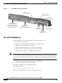
Understanding the Cisco MWR 2941 Router Interface Numbering
Slot and Port Numbering 3-2
Setup Command Facility
3-1
3-3
Cisco MWR 2941 Mobile Wireless Edge Router Software Configuration Guide, Release 12.2(33)MRB
iv
OL-21227-02
Contents
Before Starting Your Router 3-3
Using the Setup Command Facility
Configuring Global Parameters
Completing the Configuration
CHAPTER
4
3-4
3-4
3-6
Configuring the Cisco MWR 2941 Router Using the CLI
Verifying the Cisco IOS Software Version
4-1
4-1
Configuration Sequence 4-1
Summary of Steps 4-2
Configuring the Hostname and Password 4-2
Verifying the Hostname and Password 4-3
Configuring Gigabit Ethernet Interfaces 4-4
Configuring the Interface Properties 4-4
Setting the Speed and Duplex Mode 4-5
Enabling the Interface 4-6
Creating Backup Switch Interfaces 4-6
Configuring Layer 2 Interfaces 4-6
Configuring a Range of Interfaces 4-6
Defining a Range Macro 4-7
Configuring Layer 2 Optional Interface Features 4-7
Configuring HWIC-9ESW Interfaces 4-11
Configuring Stacking 4-11
Configuring VLANs 4-12
Adding a VLAN Instance 4-12
Deleting a VLAN Instance 4-12
Configuring VLAN Trunking Protocol 4-13
Configuring Resilient Ethernet Protocol (REP) 4-15
Default REP Configuration 4-15
REP Configuration Guidelines 4-15
Configuring the REP Administrative VLAN 4-16
Configuring REP Interfaces 4-17
Setting Manual Preemption for VLAN Load Balancing 4-19
Configuring SNMP Traps for REP 4-19
Monitoring REP 4-20
Configuring Ethernet Connectivity Fault Management (CFM) 4-21
Understanding Ethernet CFM 4-21
Configuring Ethernet CFM 4-30
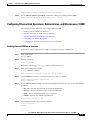
Configuring Ethernet Link Operations, Administration, and Maintenance (OAM)
Enabling Ethernet OAM on an Interface 4-33
4-33
Cisco MWR 2941 Mobile Wireless Edge Router Software Configuration Guide, Release 12.2(33)MRB
OL-21227-02
v
Contents
Stopping and Starting Link Monitoring Operations 4-34
Configuring Link Monitoring Options 4-34
Configuring Global Ethernet OAM Options Using a Template 4-35
Configuring a Port for RFI Support 4-37
Configuring Ethernet Local Management Interface (E-LMI) 4-38
Enabling Ethernet LMI on All Supported Interfaces 4-38
Enabling Ethernet LMI on a Single Supported Interface 4-38
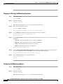
Configuring Clocking and Timing 4-39
Configuring PTP Clocking 4-39
Configuring Pseudowire-based Clocking with Adaptive Clock Recovery 4-45
Configuring Synchronous Ethernet 4-47
Configuring Network Clock Quality Selection Using REP 4-47
Verifying Clock-related Settings 4-49
Configuring MLPPP Backhaul 4-49
Configuring the Card Type 4-49
Configuring E1 Controllers 4-50
Configuring T1 Controllers 4-52
Configuring ATM IMA 4-53
Configuring a Multilink Backhaul Interface 4-54
Configuring Multiprotocol Label Switching (MPLS) 4-58
Configuring Routing Protocols 4-59
Configuring BFD 4-59
Configuring BFD for OSPF 4-59
Configuring BFD for BGP 4-61
Configuring BFD for IS-IS 4-61
Configuring BFD for Static Routes 4-63
Configuring IP Multicast 4-64
Configuring Multicast in Sparse Mode with a Static Rendezvous Point 4-64
Configuring Source-Specific Multicast 4-66
Configuring Source Specific Multicast Mapping 4-68
Configuring Multicast VPN 4-71
Verifying a Multicast Configuration 4-73
Configuring Pseudowire 4-73
Using Pseudowire Classes 4-74
Using CEM Classes 4-75
Configuring GRE Tunneling 4-76
Using Pseudowire Labels 4-77
Configuring a Backup Peer 4-78
Configuring Structure-Agnostic TDM over Packet (SAToP) 4-79
Configuring Circuit Emulation Service over Packet-Switched Network (CESoPSN)
4-79
Cisco MWR 2941 Mobile Wireless Edge Router Software Configuration Guide, Release 12.2(33)MRB
vi
OL-21227-02
Contents
Configuring Transportation of Service Using ATM over MPLS 4-80
Configuring Transportation of Service Using Ethernet over MPLS 4-87
Configuring Layer 3 Virtual Private Networks (VPNs) 4-88
Configuring Quality of Service (QoS) 4-88
QoS Limitations 4-88
Sample QoS Configuration 4-93
Configuring Classification 4-95
Configuring Marking 4-97
Configuring Congestion Management 4-101
Configuring Shaping 4-103
Configuring Ethernet Trusted Mode 4-104
Configuring Link Noise Monitor 4-104
Usage Notes 4-106
Saving Configuration Changes 4-107
Monitoring and Managing the Cisco MWR 2941 Router 4-107
Using Cisco Mobile Wireless Transport Manager (MWTM) 4-107
Configuring SNMP Support 4-108
Enabling Remote Network Management 4-112
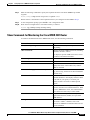
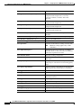
Show Commands for Monitoring the Cisco MWR 2941 Router 4-113
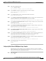
Configuring Cisco Networking Services (CNS) 4-115
Process Overview 4-116
Configuring a DHCP Server 4-116
Configuring a TFTP Server 4-117
Configuring the Cisco Configuration Engine 4-117
Verifying the Configuration 4-118
APPENDIX
A
Sample Configurations
A-1
Sample Configurations A-1
Pseudowire Configurations A-2
Asymmetric Pseudowire Configuration A-2
Pseudowire Redundancy Configuration A-10
TDM over MPLS Configuration A-14
ATM over MPLS Configuration A-17
Ethernet over MPLS Configuration A-23
GRE Tunneling Configurations A-26
CESoPSN with GRE Tunnel Backhaul A-26
ATM over MPLS AAL5 SDU Mode with GRE Backhaul
Routing Sample Configurations A-27
OSPF with BFD A-27
A-27
Cisco MWR 2941 Mobile Wireless Edge Router Software Configuration Guide, Release 12.2(33)MRB
OL-21227-02
vii
Contents
BGP with BFD A-31
IS-IS with BFD A-34
Multicast Sample Configurations A-37
Sparse Mode with a Static Rendezvous Point A-37
Source-Specific Multicast A-37
PTP Sample Configurations A-38
PTP Slave Mode with Redundancy A-38
PTP Redundancy A-43
PTP Hybrid Mode A-44
PTP Hot Standby Master Clock A-44
PTP Input Timing A-45
PTP Output Timing A-46
Layer 3 VPN Sample Configuration A-46
QoS Sample Configurations A-48
Switchport Priority A-49
Classification and Marking A-49
Priority Queuing A-51
Resilient Ethernet Protocol (REP) Sample Configuration A-51
Cisco Networking Services (CNS) Zero Touch Deployment Configuration
CFM and ELMI Sample Configuration A-54
APPENDIX
B
Cisco MWR 2941 Router Command Reference
A-54
B-1
INDEX
Cisco MWR 2941 Mobile Wireless Edge Router Software Configuration Guide, Release 12.2(33)MRB
viii
OL-21227-02
About This Guide
This section describes the objectives, audience, organization, and conventions of this software
configuration guide. It contains the following sections:
•
Document Revision History, page ix
•
Objectives, page ix
•
Audience, page x
•
Organization, page x
•
Conventions, page x
•
Related Documentation, page xi
•
Obtaining Documentation, Obtaining Support, and Security Guidelines, page xii
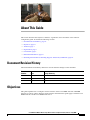
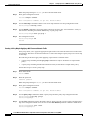
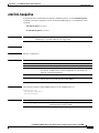
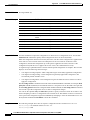
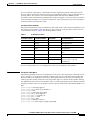
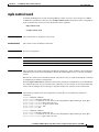
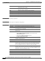
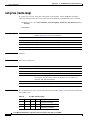
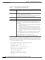
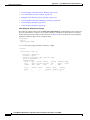
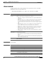
Document Revision History
The Document Revision History table below records technical changes to this document.
Document
Number
Date
Change Summary
OL-21227-01 January 2010
Initial release for Release 12.2(33)MRA.
OL-21227-02 May 2010
Updated for Release 12.2(33)MRB.
OL-21227-02 September 2010
Updated for Release 12.2(33)MRB3.
Objectives
This guide explains how to configure software features on the Cisco MWR 2941-DC and MWR
2941-DC-A routers. Unless otherwise stated, features described in this guide apply to both the Cisco
MWR 2941-DC and the Cisco MWR 2941-DC-A.
Cisco MWR 2941 Mobile Wireless Edge Router Software Configuration Guide, Release 12.2(33)MRB
OL-21227-02
ix
About This Guide
Audience
This publication is for the person responsible for configuring the router. This guide is intended for the
following audiences:
•
Customers with technical networking background and experience
•
System administrators who are familiar with the fundamentals of router-based internetworking, but
who may not be familiar with Cisco IOS software
•
System administrators who are responsible for installing and configuring internetworking
equipment, and who are familiar with Cisco IOS software
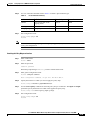
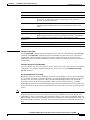
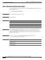
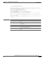
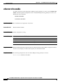
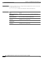
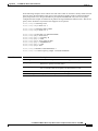
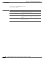
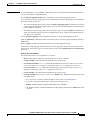
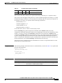
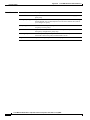
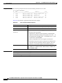
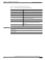
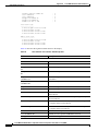
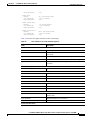
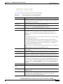
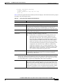
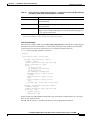
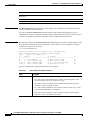
Organization
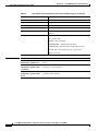
The major sections of this software configuration guide are listed in the following table:
Chapter
Title
Description
Chapter 1
Cisco MWR 2941 Router
Overview
Describes the purpose of the Cisco MWR 2941 router
and its unique software features.
Chapter 2
Cisco IOS Software Basics
Describes what you need to know about the Cisco IOS
software.
Chapter 3
First-Time Configuration
Describes how to use the setup command facility to
configure basic attributes of your router.
Chapter 4
Configuring the Cisco MWR
2941 Router Using the CLI
Describes how to use the Cisco IOS software
command-line interface (CLI) to configure basic
router functionality.
Appendix A
Sample Configurations
Provides examples of configurations.
Appendix B
Cisco MWR 2941 Router
Command Reference
Provides information about new and changed
commands.
Index
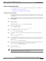
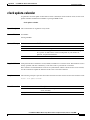
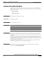
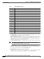
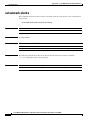
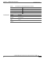
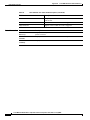
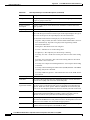
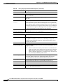
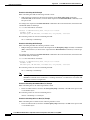
Conventions
This publication uses the following conventions to convey instructions and information.
Convention
Description
boldface font
Commands and keywords.
italic font
Variables for which you supply values.
[
Keywords or arguments that appear within square brackets are optional.
]
{x | y | z}
A choice of required keywords appears in braces separated by vertical bars. You must select one.
screen font
Examples of information displayed on the screen.
boldface screen
Examples of information the user enters.
font
Cisco MWR 2941 Mobile Wireless Edge Router Software Configuration Guide, Release 12.2(33)MRB
x
OL-21227-02
About This Guide
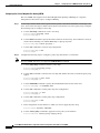
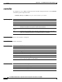
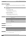
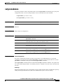
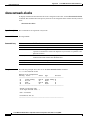
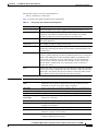
Convention
Description
<
>
Nonprinting characters, for example passwords, appear in angle brackets.
[
]
Default responses to system prompts appear in square brackets.
Note
Timesaver
Tip
Caution
Means reader take note. Notes contain helpful suggestions or references to material not covered in the
manual.
Means the described action saves time. You can save time by performing the action described in the
paragraph.
Means the following information will help you solve a problem. The tips information might not be
troubleshooting or even an action, but could be useful information, similar to a Timesaver.
Means reader be careful. In this situation, you might do something that could result in equipment
damage or loss of data.
Related Documentation
The following list includes documentation related to your product by implementation.
•
Cisco MWR 2941 Mobile Wireless Edge Router Documents
– Cisco MWR 2941 Mobile Wireless Edge Router Hardware Installation Guide
– Regulatory Compliance and Safety Information for the Cisco MWR 2941 Routers
•
Cisco Interface Cards Installation Guides
– Quick Start Guide: Interface Cards
– Cisco Interface Cards Installation Guide
•
Release Notes
– Release Notes for Cisco MWR 2941 Mobile Wireless Edge Router for Cisco IOS Release
12.2(33)MRB
Note
To obtain the latest information, access the online documentation.
Cisco MWR 2941 Mobile Wireless Edge Router Software Configuration Guide, Release 12.2(33)MRB
OL-21227-02
xi
About This Guide
Obtaining Documentation, Obtaining Support, and Security
Guidelines
For information on obtaining documentation, obtaining support, providing documentation feedback,
security guidelines, and also recommended aliases and general Cisco documents, see the monthly
What’s New in Cisco Product Documentation, which also lists all new and revised Cisco technical
documentation, at:
http://www.cisco.com/en/US/docs/general/whatsnew/whatsnew.html
Cisco MWR 2941 Mobile Wireless Edge Router Software Configuration Guide, Release 12.2(33)MRB
xii
OL-21227-02
CH A P T E R
1
Cisco MWR 2941 Router Overview
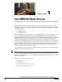
The Cisco MWR 2941 Mobile Wireless Router is cell-site access platforms specifically designed to
aggregate and transport mixed-generation radio access network (RAN) traffic. The router is used at the
cell site edge as a part of a 2G, 3G, or 4G radio access network (RAN). The Cisco MWR 2941 includes
the following models:
•
Cisco MWR 2941-DC
•
Cisco MWR 2941-DC-A
The Cisco MWR 2941 router helps enable a variety of RAN solutions by extending IP connectivity to
devices using Global System for Mobile Communications (GSM), General Packet Radio Service
(GPRS), Node Bs using HSPA or LTE, base transceiver stations (BTSs) using Enhanced Data Rates for
GSM Evolution (EDGE), Code Division Multiple Access (CDMA), CDMA-2000, EVDO, or WiMAX,
and other cell-site equipment. It transparently and efficiently transports cell-site voice, data, and
signaling traffic over IP using traditional T1/E1 circuits, including leased line, microwave, and satellite,
as well as alternative backhaul networks, including Carrier Ethernet, DSL, Ethernet in the First Mile
(EFM), and WiMAX. It also supports standards-based Internet Engineering Task Force (IETF) Internet
protocols over the RAN transport network, including those standardized at the Third-Generation
Partnership Project (3GPP) for IP RAN transport.
Custom designed for the cell site, the Cisco MWR 2941 features a small form factor, extended operating
temperature, and cell-site DC input voltages.
Note
The Cisco MWR 2941-DC and 2941-DC-A support the same features except for commands related to
the 1PPS, 10Mhz, 2.048Mhz, and 1.544Mhz timing ports that are included on the 2941-DC-A. For more
information, see the Release Notes for Cisco MWR 2941-DC Mobile Wireless Edge Router for Cisco IOS
Release 12.2(33)MRB.
This chapter includes the following sections:
•
Introduction, page 1-2
•
Features, page 1-3
•
Network Management Features, page 1-35
•
Limitations and Restrictions, page 1-36
Cisco MWR 2941 Mobile Wireless Edge Router Software Configuration Guide, Release 12.2(33)MRB
OL-21227-02
1-1
Chapter 1
Cisco MWR 2941 Router Overview
Introduction
Introduction
A typical RAN is composed of thousands of base transceiver stations (BTSs)/Node Bs, hundreds of base
station controllers/radio network controllers (BSCs/RNCs), and several mobile switching centers
(MSCs). The BTS/Node Bs and BSC/RNC are often separated by large geographic distances, with the
BTSs/Node Bs located in cell sites uniformly distributed throughout a region, and the BSCs, RNCs, and
MSCs located at suitably chosen Central Offices (CO) or mobile telephone switching offices (MTSO).
The traffic generated by a BTS/Node B is transported to the corresponding BSC/RNC across a network,
referred to as the backhaul network, which is often a hub-and-spoke topology with hundreds of
BTS/Node Bs connected to a BSC/RNC by point-to-point time division multiplexing (TDM) trunks.
These TDM trunks may be leased-line T1/E1s or their logical equivalents, such as microwave links or
satellite channels.
RAN Transport Solutions
The Cisco MWR 2941 Mobile Wireless Router supports a variety of RAN transport solutions, including
the following:
•
IP/Multiprotocol Label Switching (MPLS) RAN backhaul: Allows you to create a high-speed
backhaul for a variety of traffic types, including GSM, CDMA, HSPA/LTE, CDMA, EVDO, and
WiMAX networks.
•
Cell-site operations support networks: Facilitates telemetry to cell sites for remote operations and
network element management.
•
Cell-site IP points of presence (POPs): Allows you to offer IP services and applications at cell sites.
•
Carrier Ethernet features including Resilient Ethernet Protocol (REP), Ethernet Connectivity Fault
Management (CFM), Ethernet Local Management Interface (E-LMI), and Ethernet Operations,
Administration, and Maintenance (OAM).
•
Network clocking features including PTP, pseudowire-based clocking, and synchronous Ethernet.
•
Flexible backhaul transport including MLPPP over T1, E1, xDSL, and Ethernet.
Cisco MWR 2941 Mobile Wireless Edge Router Software Configuration Guide, Release 12.2(33)MRB
1-2
OL-21227-02
Chapter 1
Cisco MWR 2941 Router Overview
Features
Features
The following sections describe the features available in the Cisco MWR 2941 router.
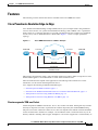
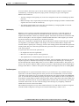
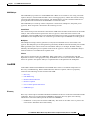
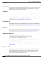
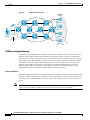
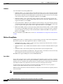
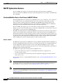
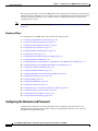
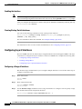
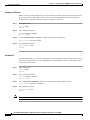
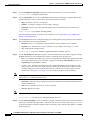
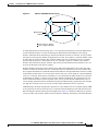
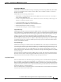
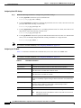
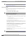
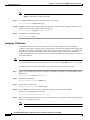
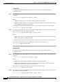
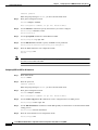
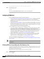
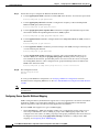
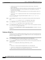
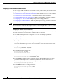
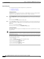
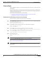
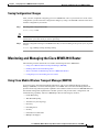
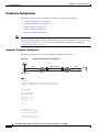
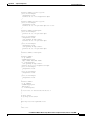
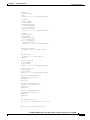
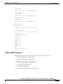
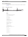
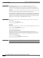
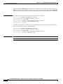
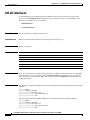
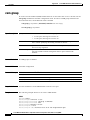
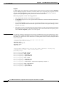
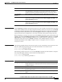
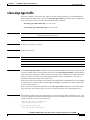
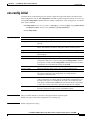
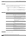
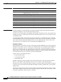
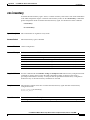
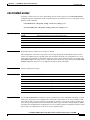
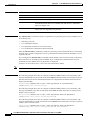
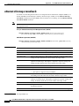
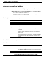
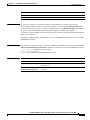
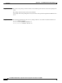
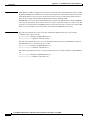
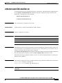
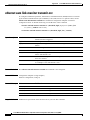
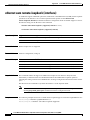
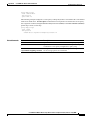
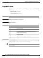
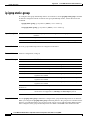
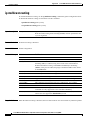
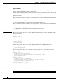
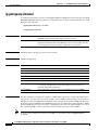
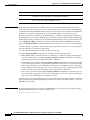
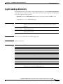
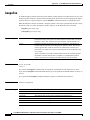
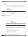
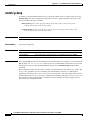
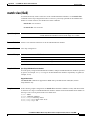
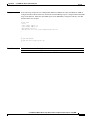
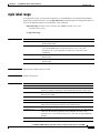
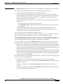
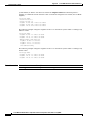
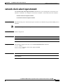
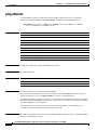
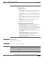
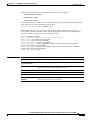
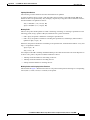
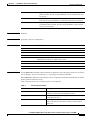
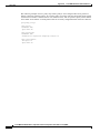
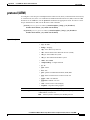
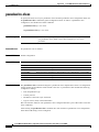
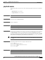
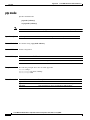
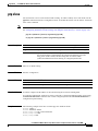
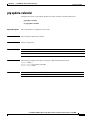
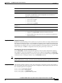
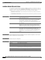
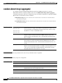
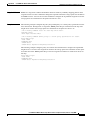
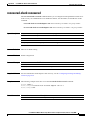
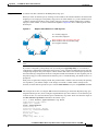
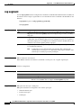
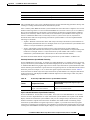
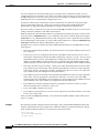
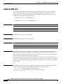
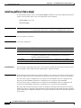
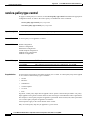
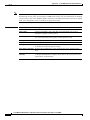
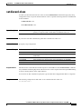
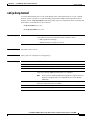
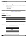
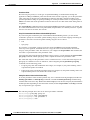
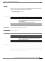
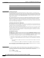
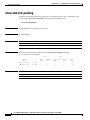
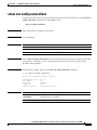
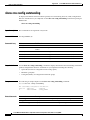
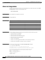
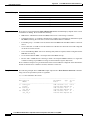
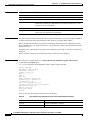
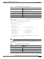
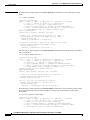
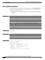
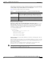
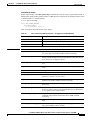
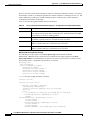
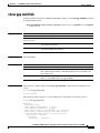
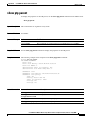
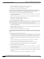
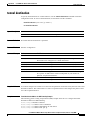
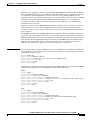
Cisco Pseudowire Emulation Edge-to-Edge
Cisco Pseudowire Emulation Edge-to-Edge (PWE3) allows you to transport traffic using traditional
services such as E1/T1 over a packet-based backhaul technology such as MPLS or IP. A pseudowire
(PW) consists of a connection between two provider edge (PE) devices that connects two attachment
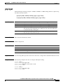
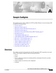
circuits (ACs), such as ATM VPIs/VCIs or E1/T1 links. Figure 1-1 shows a sample pseudowire
topology.
Figure 1-1
ATM/TDM
Cisco MWR 2941 Router in a PWE3—Example
xconnect
xconnect
ATM/TDM
MPLS/IP
Emulated Circuit
274462
Pseudowire
PWs manage encapsulation, timing, order, and other operations in order to make it transparent to users;
the PW tunnel appears as an unshared link or circuit of the emulated service.
There are limitations that impede some applications from utilizing a PW connection. For more
information, see the section describing the PW service.
Cisco supports the following standards-based PWE types:
•
Structure-agnostic TDM over Packet, page 1-3
•
Structure-aware TDM Circuit Emulation Service over Packet-Switched Network, page 1-4
•
Transportation of Service Using ATM over MPLS, page 1-4
•
Transportation of Service Using Ethernet over MPLS, page 1-4
Structure-agnostic TDM over Packet
SAToP encapsulates TDM bit-streams (T1, E1, T3, E3) as PWs over PSNs. It disregards any structure
that may be imposed on streams, in particular the structure imposed by the standard TDM framing.
The protocol used for emulation of these services does not depend on the method in which attachment
circuits are delivered to the PEs. For example, a T1 attachment circuit is treated the same way for all
delivery methods, including: PE on copper, multiplex in a T3 circuit, mapped into a virtual tributary of
Cisco MWR 2941 Mobile Wireless Edge Router Software Configuration Guide, Release 12.2(33)MRB
OL-21227-02
1-3
Chapter 1
Cisco MWR 2941 Router Overview
Features
a SONET/SDH circuit, or carried over a network using unstructured Circuit Emulation Service (CES).
Termination of specific carrier layers used between the PE and circuit emulation (CE) is performed by
an appropriate network service provider (NSP).
For instructions on how to configure SAToP, see the “Configuring Structure-Agnostic TDM over Packet
(SAToP)” section on page 4-79. For a sample SAToP configuration, see the “TDM over MPLS
Configuration” section on page A-14.
Structure-aware TDM Circuit Emulation Service over Packet-Switched Network
CESoPSN encapsulates structured (NxDS0) TDM signals as PWs over PSNs. It complements similar
work for structure-agnostic emulation of TDM bit-streams, such as PWE3-SAToP.
Emulation of NxDS0 circuits saves PSN bandwidth and supports DS0-level grooming and distributed
cross-connect applications. It also enhances resilience of CE devices due to the effects of loss of packets
in the PSN.
CESoPSN supports channel-associated signaling (CAS) for E1 and T1 interfaces. CAS provides
signaling information within each DS0 channel as opposed to using a separate signaling channel. CAS
also referred to as in-band signaling or robbed bit signaling.
For instructions on how to configure SAToP, see the “Configuring Circuit Emulation Service over
Packet-Switched Network (CESoPSN)” section on page 4-79. For a sample SAToP configuration, see
the “TDM over MPLS Configuration” section on page A-14.
Transportation of Service Using ATM over MPLS
An Asynchronous Transfer Mode (ATM) over MPLS PW is used to carry ATM cells over an MPLS
network. It is an evolutionary technology that allows you to migrate packet networks from legacy
networks, yet provides transport for legacy applications. ATM over MPLS is particularly useful for
transporting 3G voice traffic over MPLS networks.
You can configure ATM over MPLS in the following modes:
•
N-to-1 Cell Mode—Maps one or more ATM virtual channel connections (VCCs) or virtual
permanent connection (VPCs) to a single pseudowire.
•
1-to-1 Cell Mode—Maps a single ATM VCC or VPC to a single pseudowire.
•
Port Mode—Map one physical port to a single pseudowire connection.
The Cisco MWR 2941 also supports cell packing and PVC mapping for ATM over MPLS pseudowires.
For more information about how to configure ATM over MPLS, see the “Configuring Transportation of
Service Using ATM over MPLS” section on page 4-80. For sample ATM over MPLS configurations,
see the “ATM over MPLS Configuration” section on page A-17.
Transportation of Service Using Ethernet over MPLS
Ethernet over MPLS (EoMPLS) PWs provide a tunneling mechanism for Ethernet traffic through an
MPLS-enabled Layer 3 core network. EoMPLS PWs encapsulate Ethernet protocol data units (PDUs)
inside MPLS packets and use label switching to forward them across an MPLS network. EoMPLS PWs
are an evolutionary technology that allows you to migrate packet networks from legacy networks while
providing transport for legacy applications. EoMPLS PWs also simplify provisioning, since the provider
edge equipment only requires Layer 2 connectivity to the connected customer edge (CE) equipment. The
Cisco MWR 2941 implementation of EoMPLS PWs is compliant with the RFC 4447 and 4448
standards.
Cisco MWR 2941 Mobile Wireless Edge Router Software Configuration Guide, Release 12.2(33)MRB
1-4
OL-21227-02
Chapter 1
Cisco MWR 2941 Router Overview
Features
For instructions on how to create an EoMPLS PW, see the “Configuring Transportation of Service Using
Ethernet over MPLS” section on page 4-87.
Limitations
When configuring an EoMPLS pseudowire on the Cisco MWR 2941, you cannot configure an IP address
on the same interface as the pseudowire.
Generic Routing Encapsulation (GRE) Tunneling
Generic routing encapsulation (GRE) is a tunneling protocol developed by Cisco that can encapsulate a
wide variety of protocol packet types inside IP tunnels, creating a virtual point-to-point link to Cisco
routers at remote points over an IP internetwork. GRE tunneling allows you to transport a pseudowire
over an IP backhaul network when MPLS routing is not available between a cell site (BTS or Node-B)
and an aggregation point (BSC or RNC). The Cisco MWR 2941 supports GRE encapsulation for the
following PW connection types:
•
ATM over MPLS
•
SAToP
•
CESoPSN
•
Ethernet over MPLS
The Cisco MWR 2941 implementation of GRE can interoperate with the Cisco 7600 router and provides
compliance with RFCs 2784 and 4023. The Cisco MWR 2941 supports up to 128 GRE tunnels. For more
information about how to configure GRE tunneling, see the “Configuring GRE Tunneling” section on
page 4-76.
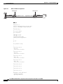
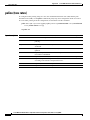
Resilient Ethernet Protocol (REP)
A REP segment is a chain of ports connected to each other and configured with a segment ID. Each
segment consists of standard (nonedge) segment ports and two user-configured edge ports. A switch can
have only two ports belonging to the same segment, and each segment port can have only one external
neighbor. A segment can go through a shared medium, but on any link, only two ports can belong to the
same segment. REP is supported only on Layer 2 trunk interfaces.
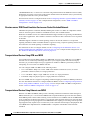
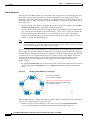
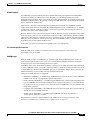
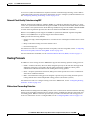
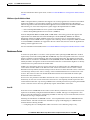
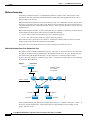
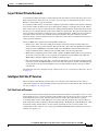
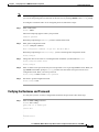
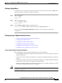
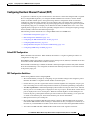
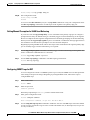
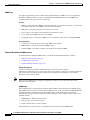
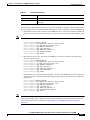
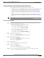
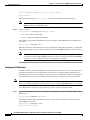
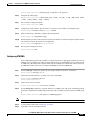
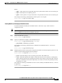
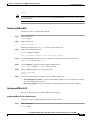
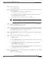
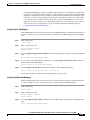
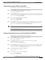
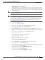
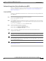
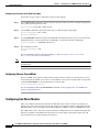
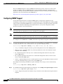
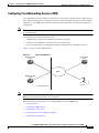
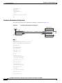
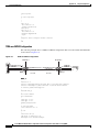
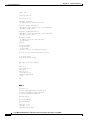
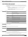
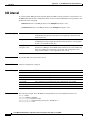
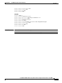
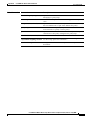
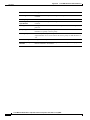
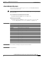
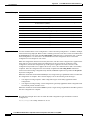
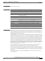
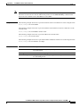
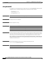
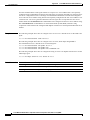
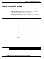
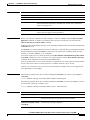
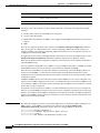
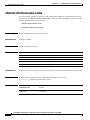
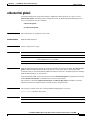
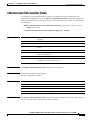
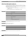
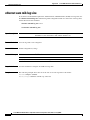
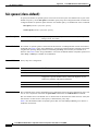
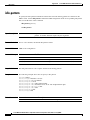
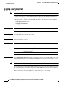
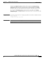
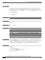
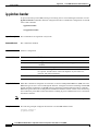
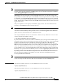
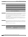
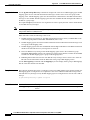
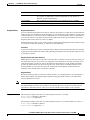
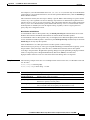
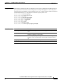
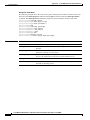
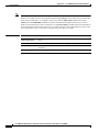
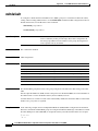
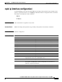
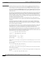
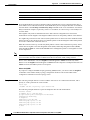
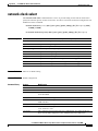
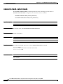
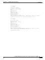
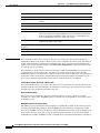
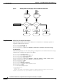
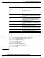
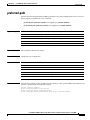
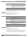
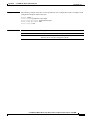
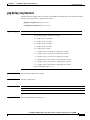
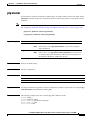
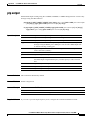
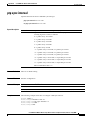
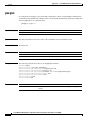
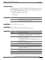
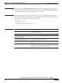
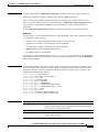
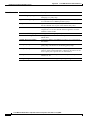
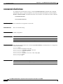
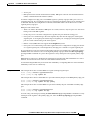
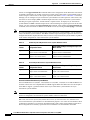
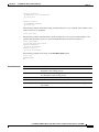
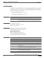
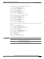
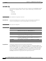
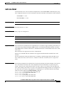
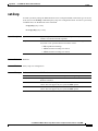
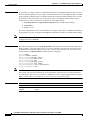
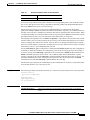
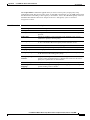
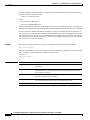
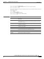
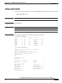
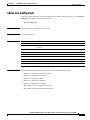
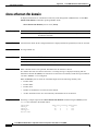
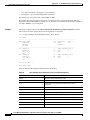
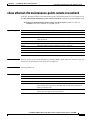
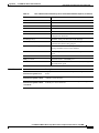
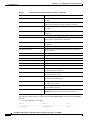
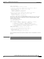
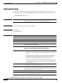
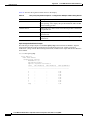
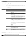
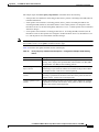
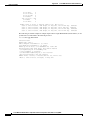
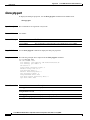
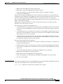
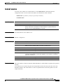
Figure 1-2 shows an example of a segment consisting of six ports spread across four switches. Ports E1
and E2 are configured as edge ports. When all ports are operational (as in the segment on the left), a
single port is blocked, shown by the diagonal line. When there is a network failure, as shown in the
diagram on the right, the blocked port returns to the forwarding state to minimize network disruption.
Cisco MWR 2941 Mobile Wireless Edge Router Software Configuration Guide, Release 12.2(33)MRB
OL-21227-02
1-5
Chapter 1
Cisco MWR 2941 Router Overview
Features
Figure 1-2
REP Open Segments
E1
Edge port
Blocked port
Link failure
E2
E1
E2
201888
E1
Figure 1-2 shows an open segment; there is no connectivity between the two edge ports. The REP
segment cannot cause a bridging loop, and you can safely connect the segment edges to any network.
All hosts connected to switches inside the segment have two possible connections to the rest of the
network through the edge ports, but only one connection is accessible at any time. If a host cannot access
its usual gateway because of a failure, REP unblocks all ports to ensure that connectivity is available
through the other gateway.
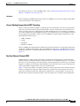
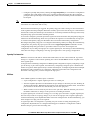
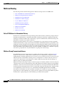
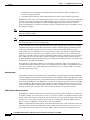
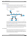
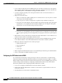
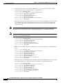
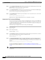
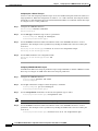
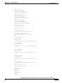
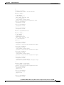
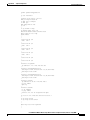
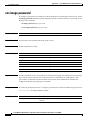
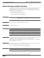
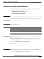
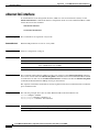
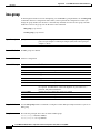
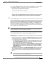
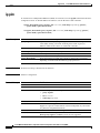
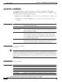
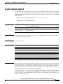
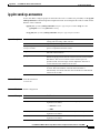
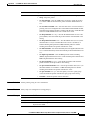
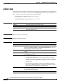
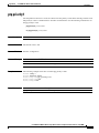
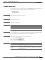
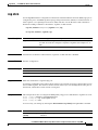
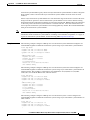
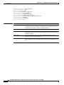
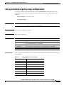
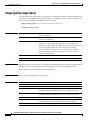
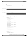
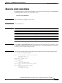
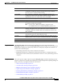
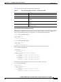
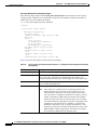
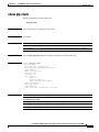
Figure 1-3 shows a segment with both edge ports located on the same switch, is a ring segment. In this
configuration, there is connectivity between the edge ports through the segment. With this configuration,
you can create a redundant connection between any two switches in the segment.
Figure 1-3
REP Ring Segment
E2
201889
E1
REP segments have these characteristics:
•
If all ports in the segment are operational, one port (referred to as the alternate port) is in the blocked
state for each VLAN.
•
If VLAN load balancing is configured, two ports in the segment control the blocked state of VLANs.
•
If one or more ports in a segment is not operational, causing a link failure, all ports forward traffic
on all VLANs to ensure connectivity.
•
In case of a link failure, the alternate ports are unblocked as quickly as possible. When the failed
link comes back up, a logically blocked port per VLAN is selected with minimal disruption to the
network.
Cisco MWR 2941 Mobile Wireless Edge Router Software Configuration Guide, Release 12.2(33)MRB
1-6
OL-21227-02
Chapter 1
Cisco MWR 2941 Router Overview
Features
You can construct almost any type of network based on REP segments. REP also supports VLAN
load-balancing, controlled by the primary edge port but occurring at any port in the segment.
REP has these limitations:
•
You must configure each segment port; an incorrect configuration can cause forwarding loops in the
networks.
•
REP can manage only a single failed port within the segment; multiple port failures within the REP
segment cause loss of network connectivity.
•
You should configure REP only in networks with redundancy. Configuring REP in a network
without redundancy causes loss of connectivity.
Link Integrity
REP does not use an end-to-end polling mechanism between edge ports to verify link integrity. It
implements local link failure detection. The REP Link Status Layer (LSL) detects its REP-aware
neighbor and establishes connectivity within the segment. All VLANs are blocked on an interface until
it detects the neighbor. After the neighbor is identified, REP determines which neighbor port should
become the alternate port and which ports should forward traffic.
Each port in a segment has a unique port ID. The port ID format is similar to that used by the spanning
tree algorithm: a port number (unique on the bridge), associated to a MAC address (unique in the
network). When a segment port is coming up, its LSL starts sending packets that include the segment ID
and the port ID. The port is declared operational after it performs a three-way handshake with a neighbor
in the same segment.
A segment port does not become operational if:
•
No neighbor has the same segment ID.
•
More than one neighbor has the same segment ID.
•
The neighbor does not acknowledge the local port as a peer.
Each port creates an adjacency with its immediate neighbor. After the neighbor adjacencies are created,
the ports negotiate to determine one blocked port for the segment, the alternate port. All other ports
become unblocked. By default, REP packets are sent to a BPDU class MAC address. The packets can
also be sent to the Cisco multicast address, which is used only to send blocked port advertisement (BPA)
messages when there is a failure in the segment. The packets are dropped by devices not running REP.
Fast Convergence
Because REP runs on a physical link basis and not on a per-VLAN basis, only one hello message is
required for all VLANs, reducing the load on the protocol. We recommend that you create VLANs
consistently on all switches in a given segment and configure the same allowed VLANs on the REP trunk
ports. To avoid the delay introduced by relaying messages in software, REP also allows some packets to
be flooded to a regular multicast address. These messages operate at the hardware flood layer (HFL) and
are flooded to the whole network, not just the REP segment. Switches that do not belong to the segment
treat them as data traffic. You can control flooding of these messages by configuring a dedicated
administrative VLAN for the whole domain.
The estimated convergence recovery time on fiber interfaces is less than 200 ms for the local segment
with 200 VLANs configured. Convergence for VLAN load balancing is 300 ms or less.
Cisco MWR 2941 Mobile Wireless Edge Router Software Configuration Guide, Release 12.2(33)MRB
OL-21227-02
1-7
Chapter 1
Cisco MWR 2941 Router Overview
Features
VLAN Load Balancing
One edge port in the REP segment acts as the primary edge port; the other as the secondary edge port.
The primary edge port always participates in VLAN load balancing in the segment. REP VLAN
balancing is achieved by blocking some VLANs at a configured alternate port and all other VLANs at
the primary edge port. When you configure VLAN load balancing, you can specify the alternate port in
one of three ways:
•
Enter the port ID of the interface. To identify the port ID of a port in the segment, enter the show
interface rep detail interface configuration command for the port.
•
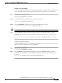
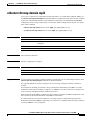
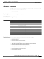
Enter the neighbor offset number of a port in the segment, which identifies the downstream neighbor
port of an edge port. The neighbor offset number range is –256 to +256; a value of 0 is invalid. The
primary edge port has an offset number of 1; positive numbers above 1 identify downstream
neighbors of the primary edge port. Negative numbers identify the secondary edge port (offset
number –1) and its downstream neighbors.
You configure offset numbers on the primary edge port by identifying the downstream position
from the primary (or secondary) edge port. You would never enter an offset value of 1 because
that is the offset number of the primary edge port itself.
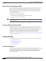
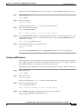
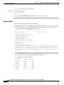
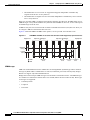
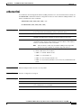
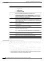
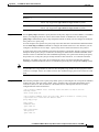
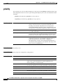
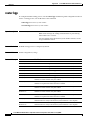
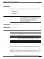
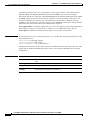
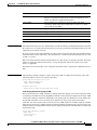
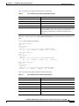
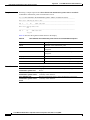
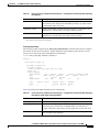
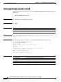
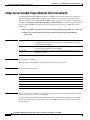
Note
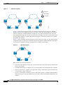
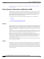
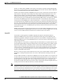
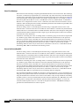
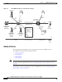
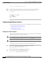
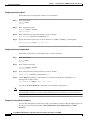
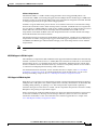
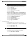
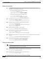
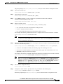
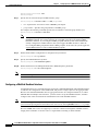
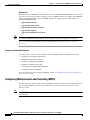
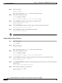
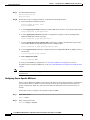
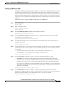
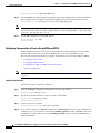
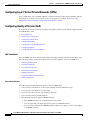
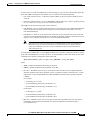
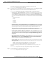
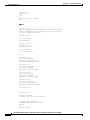
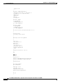
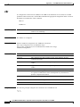
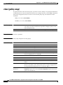
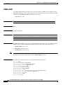
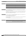
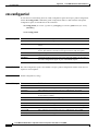
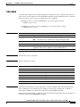
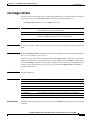
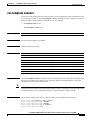
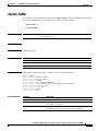
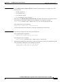
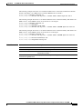
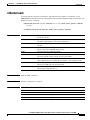
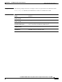
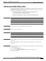
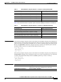
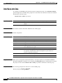
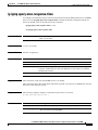
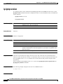
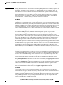
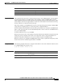
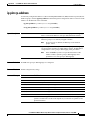
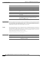
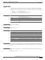
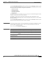
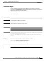
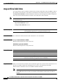
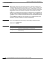
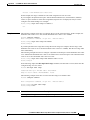
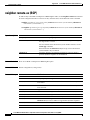
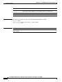
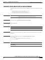
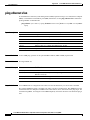
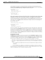
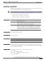
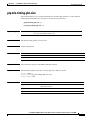
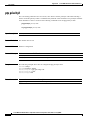
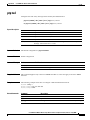
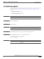
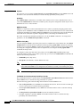
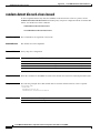
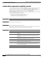
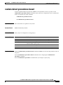
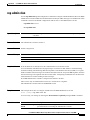
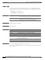
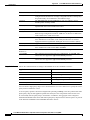
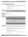
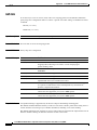
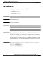
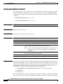
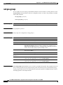
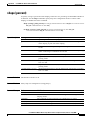
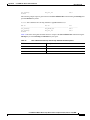
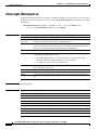
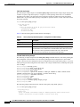
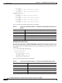
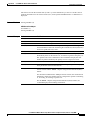
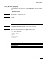
Figure 1-4 shows neighbor offset numbers for a segment where E1 is the primary edge port and E2 is
the secondary edge port. The red numbers inside the ring are numbers offset from the primary edge port;
the black numbers outside the ring show the offset numbers from the secondary edge port. Note that you
can identify all ports (except the primary edge port) by either a positive offset number (downstream
position from the primary edge port) or a negative offset number (downstream position from the
secondary edge port). If E2 became the primary edge port, its offset number would then be 1,
and E1 would be -1.
•
By entering the preferred keyword to select the port that you previously configured as the preferred
alternate port with the rep segment segment-id preferred command in interface configuration
mode.
Figure 1-4
Neighbor Offset Numbers in a Segment
-1
-9 2
E1
1
E2
10
E1 = Primary edge port
E2 = Secondary edge port
9
-2
Offset numbers from the primary edge port
Offset numbers from the secondary edge
port (negative numbers)
8 -3
-8 3
7
-7
5
-6
6
-4
-5
201890
4
When the REP segment is complete, all VLANs are blocked. When you configure VLAN load balancing,
you must also configure triggers in one of two ways
•
Manually trigger VLAN load balancing at any time by entering the rep preempt segment
segment-id privileged EXEC command on the switch that has the primary edge port.
Cisco MWR 2941 Mobile Wireless Edge Router Software Configuration Guide, Release 12.2(33)MRB
1-8
OL-21227-02
Chapter 1
Cisco MWR 2941 Router Overview
Features
•
Note
Configure a preempt delay time by entering the rep preempt delay seconds interface configuration
command. After a link failure and recovery, VLAN load balancing begins after the configured
preemption time period elapses. Note that the delay timer restarts if another port fails before the time
has elapsed.
When VLAN load balancing is configured, it does not start working until triggered by either manual
intervention or a link failure and recovery.
When VLAN load balancing is triggered, the primary edge port sends a message to alert all interfaces
in the segment about the preemption. When the secondary port receives the message, it is reflected into
the network to notify the alternate port to block the set of VLANs specified in the message and to notify
the primary edge port to block the remaining VLANs.
You can also configure a particular port in the segment to block all VLANs. Only the primary edge port
initiates VLAN load balancing, which is not possible if the segment is not terminated by an edge port
on each end. The primary edge port determines the local VLAN load balancing configuration.
Reconfigure the primary edge port to reconfigure load balancing. When you change the load balancing
configuration, the primary edge port again waits for the rep preempt segment command or for the
configured preempt delay period after a port failure and recovery before executing the new
configuration. If you change an edge port to a regular segment port, the existing VLAN load balancing
status does not change. Configuring a new edge port might cause a new topology configuration.
Spanning Tree Interaction
REP does not interact with STP or with the Flex Link feature, but can coexist with both. A port that
belongs to a segment is removed from spanning tree control and STP BPDUs are not accepted or sent
from segment ports.
To migrate from an STP ring configuration to REP segment configuration, begin by configuring a single
port in the ring as part of the segment, and continue by configuring contiguous ports to minimize the
number of segments. Each segment always contains a blocked port, so multiple segments means multiple
blocked ports and a potential loss of connectivity. When the segment has been configured in both
directions to the edge ports, you then configure the edge ports.
REP Ports
Ports in REP segments are Failed, Open, or Alternate.
•
A port configured as a regular segment port starts as a failed port.
•
After the neighbor adjacencies are determined, the port changes to alternate port state, blocking all
VLANs on the interface. Blocked port negotiations occur and when the segment settles, one blocked
port remains in the alternate role, and all other ports become open ports.
•
When a failure occurs in a link, all ports move to the open state. When the alternate port receives
the failure notification, it changes to the open state, forwarding all VLANs.
A regular segment port converted to an edge port, or an edge port converted to a regular segment port,
does not always result in a topology change. If you convert an edge port into a regular segment port,
VLAN load balancing is not implemented unless it has been configured. For VLAN load balancing, you
must configure two edge ports in the segment.
A segment port that is reconfigured as a spanning tree port restarts according the spanning tree
configuration. By default, this is a designated blocking port. If PortFast is configured or if STP is
disabled, the port goes into the forwarding state.
Cisco MWR 2941 Mobile Wireless Edge Router Software Configuration Guide, Release 12.2(33)MRB
OL-21227-02
1-9
Chapter 1
Cisco MWR 2941 Router Overview
Features
For instructions on how to configure REP, see the “Configuring Resilient Ethernet Protocol (REP)”
section on page 4-15.
Ethernet Operations, Administration, and Maintenance (OAM)
Ethernet Operations, Administration, and Maintenance (OAM) is a protocol for installing, monitoring,
and troubleshooting Ethernet metropolitan-area networks (MANs) and Ethernet WANs. It relies on a
new, optional sublayer in the data link layer of the Open Systems Interconnection (OSI) model. The
OAM features covered by this protocol are Discovery, Link Monitoring, Remote Fault Detection,
Remote Loopback, and Cisco Proprietary Extensions.
The following sections describe the Ethernet OAM features supported on the Cisco MWR 2941:
•
Overview
•
Link OAM
•
Ethernet Connectivity Fault Management (CFM)
•
Ethernet Local Management Interface (E-LMI)
Overview
Ethernet OAM is a protocol for installing, monitoring, and troubleshooting metro Ethernet networks and
Ethernet WANs. It relies on a new, optional sublayer in the data link layer of the OSI model. Ethernet
OAM can be implemented on any full-duplex point-to-point or emulated point-to-point Ethernet link. A
system-wide implementation is not required; OAM can be deployed on particular interfaces for part of
a system.
Normal link operation does not require Ethernet OAM. OAM frames, called OAM protocol data units
(PDUs), use the slow protocol destination MAC address 0180.c200.0002. They are intercepted by the
MAC sublayer and cannot propagate beyond a single hop within an Ethernet network.
Ethernet OAM is a relatively slow protocol with modest bandwidth requirements. The frame
transmission rate is limited to a maximum of 10 frames per second; therefore, the impact of OAM on
normal operations is negligible. However, when link monitoring is enabled, the CPU must poll error
counters frequently. In this case, the required CPU cycles will be proportional to the number of
interfaces that have to be polled.
Two major components, the OAM client and the OAM sublayer, make up Ethernet OAM. The following
sections describe these components.
OAM Client
The OAM client is responsible for establishing and managing Ethernet OAM on a link. The OAM client
also enables and configures the OAM sublayer. During the OAM discovery phase, the OAM client
monitors OAM PDUs received from the remote peer and enables OAM functionality on the link based
on local and remote state as well as configuration settings. Beyond the discovery phase (at steady state),
the OAM client is responsible for managing the rules of response to OAM PDUs and managing the OAM
remote loopback mode.
Cisco MWR 2941 Mobile Wireless Edge Router Software Configuration Guide, Release 12.2(33)MRB
1-10
OL-21227-02
Chapter 1
Cisco MWR 2941 Router Overview
Features
OAM Sublayer
The OAM sublayer presents two standard IEEE 802.3 MAC service interfaces: one facing toward the
superior sublayers, which include the MAC client (or link aggregation), and the other interface facing
toward the subordinate MAC control sublayer. The OAM sublayer provides a dedicated interface for
passing OAM control information and OAM PDUs to and from a client.
The OAM sublayer is made up of three components: control block, multiplexer, and packet parser
(p-parser). Each component is described in the following sections.
Control Block
The control block provides the interface between the OAM client and other blocks internal to the OAM
sublayer. The control block incorporates the discovery process, which detects the existence and
capabilities of remote OAM peers. It also includes the transmit process that governs the transmission of
OAM PDUs to the multiplexer and a set of rules that govern the receipt of OAM PDUs from the p-parser.
Multiplexer
The multiplexer manages frames generated (or relayed) from the MAC client, control block, and
p-parser. The multiplexer passes through frames generated by the MAC client untouched. It passes OAM
PDUs generated by the control block to the subordinate sublayer; for example, the MAC sublayer.
Similarly, the multiplexer passes loopback frames from the p-parser to the same subordinate sublayer
when the interface is in OAM remote loopback mode.
P-Parser
The p-parser classifies frames as OAM PDUs, MAC client frames, or loopback frames and then
dispatches each class to the appropriate entity. OAM PDUs are sent to the control block. MAC client
frames are passed to the superior sublayer. Loopback frames are dispatched to the multiplexer.
Link OAM
Link OAM is defined in the IEEE 802.3ah and IEEE 802.3 Clause 57 standards and provides for
discovery, Link Monitoring, Remote Fault Indication, Remote Loopback, and Cisco proprietary
extensions. The following sections describe Link OAM:
•
Discovery
•
Link Monitoring
•
Remote Failure Indication
•
Remote Loopback
•
Cisco Vendor-Specific Extensions
•
OAM Messages
Discovery
Discovery is the first phase of Ethernet OAM and it identifies the devices in the network and their OAM
capabilities. Discovery uses information OAM PDUs. During the discovery phase, the following
information is advertised within periodic information OAM PDUs:
•
OAM mode—Conveyed to the remote OAM entity. The mode can be either active or passive and
can be used to determine device functionality.
Cisco MWR 2941 Mobile Wireless Edge Router Software Configuration Guide, Release 12.2(33)MRB
OL-21227-02
1-11
Chapter 1
Cisco MWR 2941 Router Overview
Features
•
OAM configuration (capabilities)—Advertises the capabilities of the local OAM entity. With this
information a peer can determine what functions are supported and accessible; for example,
loopback capability.
•
OAM PDU configuration—Includes the maximum OAM PDU size for receipt and delivery. This
information along with the rate limiting of 10 frames per second can be used to limit the bandwidth
allocated to OAM traffic.
•
Platform identity—A combination of an organization unique identifier (OUI) and 32-bits of
vendor-specific information. OUI allocation, controlled by the IEEE, is typically the first three bytes
of a MAC address.
Discovery includes an optional phase in which the local station can accept or reject the configuration of
the peer OAM entity. For example, a node may require that its partner support loopback capability to be
accepted into the management network. These policy decisions may be implemented as vendor-specific
extensions.
Link Monitoring
Link monitoring in Ethernet OAM detects and indicates link faults under a variety of conditions. Link
monitoring uses the event notification OAM PDU and sends events to the remote OAM entity when there
are problems detected on the link. The error events include the following:
•
Error Symbol Period (error symbols per second)—The number of symbol errors that occurred
during a specified period exceeded a threshold. These errors are coding symbol errors.
•
Error Frame (error frames per second)—The number of frame errors detected during a specified
period exceeded a threshold.
•
Error Frame Period (error frames per n frames)—The number of frame errors within the last n
frames has exceeded a threshold.
•
Error Frame Seconds Summary (error seconds per m seconds)—The number of error seconds
(1-second intervals with at least one frame error) within the last m seconds has exceeded a threshold.
Because IEEE 802.3ah OAM does not provide a guaranteed delivery of any OAM PDU, the event
notification OAM PDU may be sent multiple times to reduce the probability of a lost notification. A
sequence number is used to recognize duplicate events.
Remote Failure Indication
Faults in Ethernet connectivity that are caused by slowly deteriorating quality are difficult to detect.
Ethernet OAM provides a mechanism for an OAM entity to convey these failure conditions to its peer
via specific flags in the OAM PDU. The following failure conditions can be communicated:
•
Link Fault—Loss of signal is detected by the receiver; for instance, the peer's laser is
malfunctioning. A link fault is sent once per second in the information OAM PDU. Link fault
applies only when the physical sublayer is capable of independently transmitting and receiving
signals.
•
Dying Gasp—An unrecoverable condition has occurred; for example, a power failure. This type of
condition is vendor specific. A notification about the condition may be sent immediately and
continuously.
•
Critical Event—An unspecified critical event has occurred. This type of event is vendor specific. A
critical event may be sent immediately and continuously.
Cisco MWR 2941 Mobile Wireless Edge Router Software Configuration Guide, Release 12.2(33)MRB
1-12
OL-21227-02
Chapter 1
Cisco MWR 2941 Router Overview
Features
Remote Loopback
An OAM entity can put its remote peer into loopback mode using the loopback control OAM PDU.
Loopback mode helps an administrator ensure the quality of links during installation or when
troubleshooting. In loopback mode, every frame received is transmitted back on the same port except for
OAM PDUs and pause frames. The periodic exchange of OAM PDUs must continue during the loopback
state to maintain the OAM session.
The loopback command is acknowledged by responding with an information OAM PDU with the
loopback state indicated in the state field. This acknowledgement allows an administrator, for example,
to estimate if a network segment can satisfy a service-level agreement. Acknowledgement makes it
possible to test delay, jitter, and throughput.
When an interface is set to the remote loopback mode the interface no longer participates in any other
Layer 2 or Layer 3 protocols such as Spanning Tree Protocol (STP) or Open Shortest Path First (OSPF).
The reason is that when two connected ports are in a loopback session, no frames other than the OAM
PDUs are sent to the CPU for software processing. The non-OAM PDU frames are either looped back
at the MAC level or discarded at the MAC level.
From a user's perspective, an interface in loopback mode is in a link-up state.
Cisco Vendor-Specific Extensions
Ethernet OAM allows vendors to extend the protocol by allowing them to create their own
type-length-value (TLV) fields.
OAM Messages
Ethernet OAM messages or OAM PDUs are standard length, untagged Ethernet frames within the
normal frame length bounds of 64 to 1518 bytes. The maximum OAM PDU frame size exchanged
between two peers is negotiated during the discovery phase.
OAM PDUs always have the destination address of slow protocols (0180.c200.0002) and an Ethertype
of 8809. OAM PDUs do not go beyond a single hop and have a hard-set maximum transmission rate of
10 OAM PDUs per second. Some OAM PDU types may be transmitted multiple times to increase the
likelihood that they are successfully received on a deteriorating link.
Four types of OAM messages are supported:
•
Information OAM PDU—A variable-length OAM PDU that is used for discovery. This OAM PDU
includes local, remote, and organization-specific information.
•
Event notification OAM PDU—A variable-length OAM PDU that is used for link monitoring. This
type of OAM PDU may be transmitted multiple times to increase the chance of a successful receipt;
for example, in the case of high-bit errors. Event notification OAM PDUs also may include a time
stamp when generated.
•
Loopback control OAM PDU—An OAM PDU fixed at 64 bytes in length that is used to enable or
disable the remote loopback command.
•
Vendor-specific OAM PDU—A variable-length OAM PDU that allows the addition of
vendor-specific extensions to OAM.
For instructions on how to configure Ethernet Link OAM, see the “Configuring Ethernet Link
Operations, Administration, and Maintenance (OAM)” section on page 4-33.
Cisco MWR 2941 Mobile Wireless Edge Router Software Configuration Guide, Release 12.2(33)MRB
OL-21227-02
1-13
Chapter 1
Cisco MWR 2941 Router Overview
Features
Ethernet Connectivity Fault Management (CFM)
The Cisco MWR 2941 supports Ethernet Connectivity Fault Management (CFM) as defined in 802.1ag
Draft 1.0. Ethernet Connectivity Fault Management (CFM) is an end-to-end per-service-instance
Ethernet layer operations, administration, and maintenance (OAM) protocol. It includes proactive
connectivity monitoring, fault verification, and fault isolation for large Ethernet metropolitan-area
networks (MANs) and WANs.
Ethernet CFM provides the following benefits:
Note
•
End-to-end service-level OAM technology
•
Reduced operating expense for service provider Ethernet networks
•
Competitive advantage for service providers
Release 12.2(33)MRA supports the Draft 1.0 version of Ethernet CFM; it does not support the IEEE
802.1ag-2007 version.
For instructions on how to configure CFM, see the “Configuring Ethernet CFM” section on page 4-30.
Ethernet Local Management Interface (E-LMI)
Ethernet Local Management Interface (LMI) is an Ethernet layer operation, administration, and
management (OAM) protocol. It provides information that enables autoconfiguration of customer edge
(CE) devices and provides the status of Ethernet virtual connections (EVCs) for large Ethernet
metropolitan-area networks (MANs) and WANs. Specifically, Ethernet LMI notifies a CE device of the
operating state of an EVC and the time when an EVC is added or deleted. Ethernet LMI also
communicates the attributes of an EVC and a user-network interface (UNI) to a CE device.
For instructions on how to configure E-LMI, see the “Configuring Ethernet Local Management Interface
(E-LMI)” section on page 4-38.
Clocking and Timing
The following sections describe the clocking and timing features available on the Cisco MWR 2941.
•
Network Clocking Overview
•
Precision Timing Protocol (PTP)
•
Pseudowire-based Clocking
•
Synchronous Ethernet
Network Clocking Overview
Clock synchronization is important for a variety of applications, including synchronization of radio cell
towers. While legacy TDM protocols incorporate timing features, packet-switched networks such as
Ethernet do not natively include these features. The Cisco MWR 2941 supports legacy TDM
technologies while supporting a variety of technologies that distribute clocking information over
packet-switched networks.
Cisco MWR 2941 Mobile Wireless Edge Router Software Configuration Guide, Release 12.2(33)MRB
1-14
OL-21227-02
Chapter 1
Cisco MWR 2941 Router Overview
Features
Clocking is typically distributed from the core network outward to the BTS or Node B at the network
edge. The Cisco MWR 2941 receives and transmits clocking information using any of the following
ports:
•
T1/E1
•
Ethernet (GigabitEthernet and FastEthernet)
•
DSL
•
BITS/SYNC port
•
1PPS
•
1.544Mhz
•
2.048Mhz
•
10Mhz
Precision Timing Protocol (PTP)
The Cisco MWR 2941 supports the Precision Time Protocol (PTP) as defined by the IEEE 1588-2008
standard. PTP provides for accurate time synchronization on over packet-switched networks. Nodes
within a PTP network can act in one of the following roles:
•
Grandmaster—A device on the network physically attached to the primary time source. All other
clocks are ultimately synchronized to the grandmaster clock.
•
Ordinary clock—An ordinary clock is a 1588 clock with a single PTP port that can serve in one of
the following roles:
– Master mode—Distributes timing information over the network to one or more slave clocks,
thus allowing the slave to synchronize its clock to the master.
– Slave mode—Synchronizes its clock to a master clock.
•
Boundary clock—The device participates in selecting the best master clock and can act as the master
clock if no better clocks are detected.
•
Transparent clock—A device such as a switch that calculates the time it requires to forward traffic
and updates the PTP time correction field to account for the delay, making the device transparent in
terms of timing calculations.
Note
The Cisco MWR 2941 does not currently act as a boundary clock or a transparent clock.
Note
The 1588-2008 standard defines other clocking devices that are not described here.
PTP Domains
PTP devices use a best master clock algorithm to determine the most accurate clock on a network and
construct a clocking hierarchy based on the grandmaster clock. A given clocking hierarchy is called a
PTP domain.
Cisco MWR 2941 Mobile Wireless Edge Router Software Configuration Guide, Release 12.2(33)MRB
OL-21227-02
1-15
Chapter 1
Cisco MWR 2941 Router Overview
Features
Clock synchronization
PTP master devices periodically launch an exchange of messages with slave devices to help each slave
clock recompute the offset between its clock and the master clock. Periodic clock synchronization
mitigates any drift between the master and slave clocks.
PTP Redundancy
The Cisco MWR 2941 supports the multicast- and unicast-based timing as specified in the 1588-2008
standard. The Cisco MWR 2941 can use multicast routing to establish redundant paths between an
external PTP client and one or more PTP multicast master clocks.
When configured as a multicast PTP router, the Cisco MWR 2941 selects the best path toward a
Rendezvous Point (RP) using the active routing protocol, sends a Cisco Protocol Independent Multicast
(PIM) join message to the RP, and forwards PTP multicast messages to the PTP client. The
Cisco MWR 2941 also supports PIM forwarding. For instructions on how to configure PTP redundancy
using multicast, see the “Configuring IP Multicast” section on page 4-64.
Hot Standby Master Clock
The Cisco MWR 2941 supports a hot standby master clock for PTP clocking; the Cisco MWR 2941
selects the best clock source between two PTP master clocks and switches dynamically between them if
the clock quality of the standby clock is greater than that of the current master clock. For instructions on
how to configure a hot standby master clock, see the “Configuring PTP Clocking” section on page 4-39.
Hybrid Clocking
The Cisco MWR 2941 supports a hybrid clocking mode that uses clock frequency obtained from the
synchronous Ethernet port while using phase (ToD or 1PPS) obtained using PTP. For instructions on
how to configure hybrid clocking, see the “Configuring PTP Clocking” section on page 4-39.
Pseudowire-based Clocking
Pseudowire-based clocking allows the Cisco MWR 2941 router to
•
Transmit and receive clocking information over a pseudowire interface
•
Receive clocking over a virtual pseudowire interface.
The Cisco MWR 2941 can transmit clocking information within packet headers (in-band) or as a
separate packet stream (out-of-band).
Pseudowire-based clocking also supports adaptive clock recovery (ACR), which allows the
Cisco MWR 2941 to recover clocking from the headers of a packet stream. For instructions on how to
configure pseudowire-based clocking, see the “Configuring Clocking and Timing” section on page 4-39.
For more information about using pseudowires, see the “Cisco Pseudowire Emulation Edge-to-Edge”
section on page 1-3.
Synchronous Ethernet
Synchronous ethernet is a timing technology that allows the Cisco MWR 2941 to transport frequency
and time information over Ethernet. Because frequency and time are embedded in Ethernet packets,
synchronous Ethernet must be supported by each network element in the synchronization path.
Synchronous Ethernet is defined in the ITU-T G.781, G.8261, G.8262, and G.8264, Telcordia
GR-253-CORE, and Telcordia GR-1244-CORE standards.
Cisco MWR 2941 Mobile Wireless Edge Router Software Configuration Guide, Release 12.2(33)MRB
1-16
OL-21227-02
Chapter 1
Cisco MWR 2941 Router Overview
Features
You can use synchronous Ethernet in conjunction with an external timing technology such as GPS to
synchronize timing across the network. For instructions on how to configure synchronous Ethernet, see
the “Configuring Clocking and Timing” section on page 4-39.
Network Clock Quality Selection using REP
Ethernet Synchronization Message Channel (ESMC) is a method for indicating the quality of a clock
source on a synchronous Ethernet network segment. ESMC is described in the G.8264 (2008) standard
and is similar to the Synchronization Status Message (SSM) message used in SONET and SDH. ESMC
is based on the Organization Specific Slow Protocol defined in the IEEE 802.3 standard.
Release 12.2(33)MRA provides support for ESMC for synchronous Ethernet segments using REP.
Release 12.2(33)MRA does not provide support the G.8264 standard.
ESMC provides the following benefits:
•
Quality level (QL) enabled implementation – Ensures the use of the highest available level of clock
quality.
•
Helps a node derive timing from most reliable source.
•
Prevents timing loops.
For instructions on how to configure network clock quality selection using REP, see the “Configuring
Network Clock Quality Selection Using REP” section on page 4-47.
For more information about REP, see the “Resilient Ethernet Protocol (REP)” section on page 1-5.
Routing Protocols
In addition to static routing, the Cisco MWR 2941 supports the following dynamic routing protocols:
•
OSPF—An Interior Gateway Protocol (IGP) designed expressly for IP networks that supports IP
subnetting and tagging of externally derived routing information. OSPF also allows packet
authentication and uses IP multicast when sending and receiving packets.
•
IS-IS—An Open System Interconnection (OSI) protocol that specifies how routers communicate
with routers in different domains.
•
BGP—An interdomain routing protocol designed to provide loop-free routing between separate
routing domains that contain independent routing policies (autonomous systems).
For instructions on how to configure routing on the Cisco MWR 2941, see the “Configuring Routing
Protocols” section on page 4-59.
Bidirectional Forwarding Detection
Bidirectional Forwarding Detection (BFD) provides a low-overhead, short-duration method of detecting
failures in the forwarding path between two adjacent routers, including the interfaces, data links, and
forwarding planes. BFD is a detection protocol that you enable at the interface and routing protocol
levels. For instructions on how to configure BFD, see the “Configuring BFD” section on page 4-59.
Cisco MWR 2941 Mobile Wireless Edge Router Software Configuration Guide, Release 12.2(33)MRB
OL-21227-02
1-17
Chapter 1
Cisco MWR 2941 Router Overview
Features
Multicast Routing
The following sections describe the support for multicast routing on the Cisco MWR 2941.
•
Role of IP Multicast in Information Delivery
•
Multicast Group Transmission Scheme
•
IP Multicast Group Addressing
•
IP Multicast Address Scoping
•
Layer 2 Multicast Addresses
•
IP Multicast Delivery Modes
•
Protocol Independent Multicast
•
Multicast Group Modes
•
Rendezvous Points
•
Multicast Forwarding
Role of IP Multicast in Information Delivery
IP multicast is a bandwidth-conserving technology that reduces traffic by delivering a single stream of
information simultaneously to potentially thousands of businesses and homes. Applications that take
advantage of multicast include video conferencing, corporate communications, distance learning, and
distribution of software, stock quotes, and news.
IP multicast routing enables a host (source) to send packets to a group of hosts (receivers) anywhere
within the IP network by using a special form of IP address called the IP multicast group address. The
sending host inserts the multicast group address into the IP destination address field of the packet and
IP multicast routers and multilayer switches forward incoming IP multicast packets out all interfaces that
lead to the members of the multicast group. Any host, regardless of whether it is a member of a group,
can send to a group. However, only the members of a group receive the message.
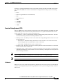
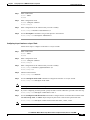
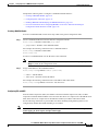
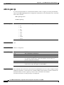
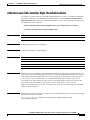
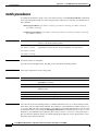
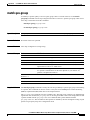
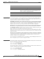
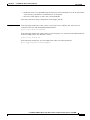
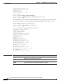
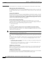
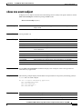
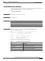
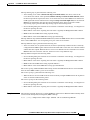
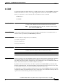
Multicast Group Transmission Scheme
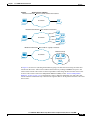
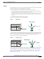
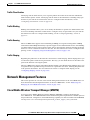
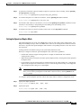
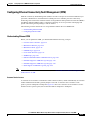
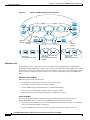
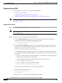
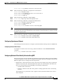
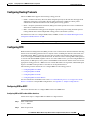
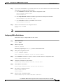
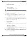
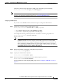
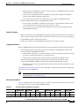
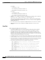
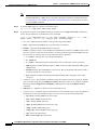
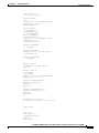
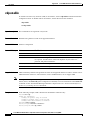
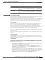
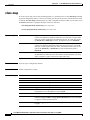
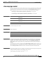
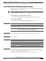
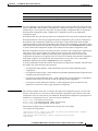
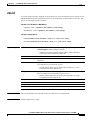
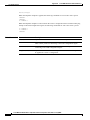
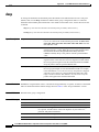
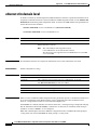
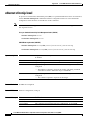
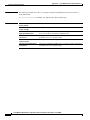
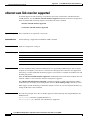
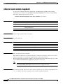
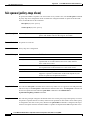
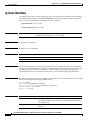
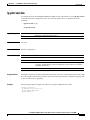
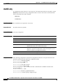
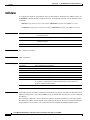
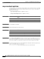
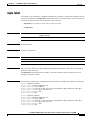
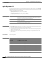
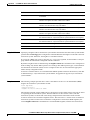
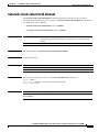
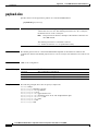
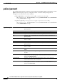
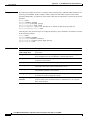
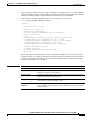
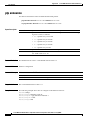
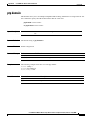
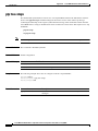
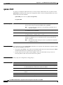
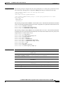
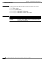
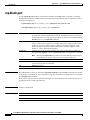
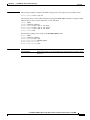
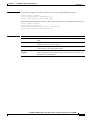
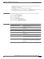
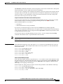
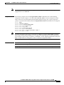
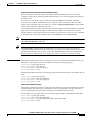
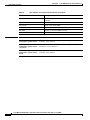
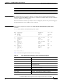
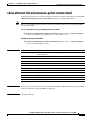
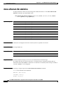
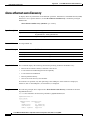
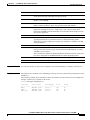
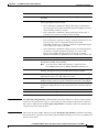
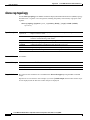
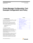
IP communication consists of hosts that act as senders and receivers of traffic as shown in Figure 5.
Senders are called sources. Traditional IP communication is accomplished by a single host source
sending packets to another single host (unicast transmission) or to all hosts (broadcast transmission). IP
multicast provides a third scheme, allowing a host to send packets to a subset of all hosts (multicast
transmission). This subset of receiving hosts is called a multicast group. The hosts that belong to a
multicast group are called group members.
Multicast is based on this group concept. A multicast group is an arbitrary number of receivers that join
a group in order to receive a particular data stream. This multicast group has no physical or geographical
boundaries—the hosts can be located anywhere on the Internet or on any private internetwork. Hosts that
are interested in receiving data from a source to a particular group must join that group. Joining a group
is accomplished by a host receiver by way of the Internet Group Management Protocol (IGMP).
In a multicast environment, any host, regardless of whether it is a member of a group, can send to a
group. However, only the members of a group can receive packets sent to that group. Multicast packets
are delivered to a group using best-effort reliability, just like IP unicast packets.
Cisco MWR 2941 Mobile Wireless Edge Router Software Configuration Guide, Release 12.2(33)MRB
1-18
OL-21227-02
Chapter 1
Cisco MWR 2941 Router Overview
Features
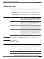
Figure 5
IP Transmission Schemes
Unicast transmission One host sends and the other receives.
IP network
Receiver
Source
Broadcast transmission One sender to all receivers.
IP network
Source
Receivers
Multicast transmission One sender to a group of receivers.
Multicast Group
IP network
Receivers
ers
121921
Source
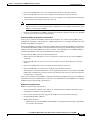
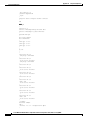
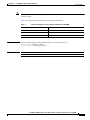
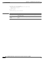
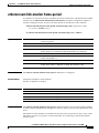
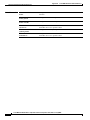
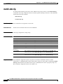
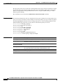
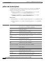
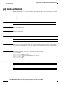
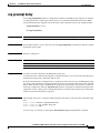
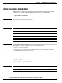
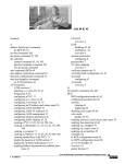
In Figure 6, the receivers (the designated multicast group) are interested in receiving the video data
stream from the source. The receivers indicate their interest by sending an IGMP host report to the
routers in the network. The routers are then responsible for delivering the data from the source to the
receivers. The routers use Protocol Independent Multicast (PIM) (see the “Protocol Independent
Multicast” section on page 1-23) to dynamically create a multicast distribution tree. The video data
stream will then be delivered only to the network segments that are in the path between the source and
the receivers.
Cisco MWR 2941 Mobile Wireless Edge Router Software Configuration Guide, Release 12.2(33)MRB
OL-21227-02
1-19
Chapter 1
Cisco MWR 2941 Router Overview
Features
Figure 6
Multicast Transmission
Multicast
Group
Receiver A
Receiver B
Source
Receiver D
121931
Receiver C
IP Multicast Group Addressing
A multicast group is identified by its multicast group address. Multicast packets are delivered to that
multicast group address. Unlike unicast addresses that uniquely identify a single host, multicast IP
addresses do not identify a particular host. To receive the data sent to a multicast address, a host must
join the group that address identifies. The data is sent to the multicast address and received by all the
hosts that have joined the group indicating that they wish to receive traffic sent to that group. The
multicast group address is assigned to a group at the source. Network administrators who assign
multicast group addresses must make sure the addresses conform to the multicast address range
assignments reserved by the Internet Assigned Numbers Authority (IANA).
IP Class D Addresses
IP multicast addresses have been assigned to the IPv4 Class D address space by IANA. The high-order
four bits of a Class D address are 1110. Therefore, host group addresses can be in the range 224.0.0.0 to
239.255.255.255. A multicast address is chosen at the source (sender) for the receivers in a multicast
group.
Note
The Class D address range is used only for the group address or destination address of IP multicast
traffic. The source address for multicast datagrams is always the unicast source address.
Cisco MWR 2941 Mobile Wireless Edge Router Software Configuration Guide, Release 12.2(33)MRB
1-20
OL-21227-02
Chapter 1
Cisco MWR 2941 Router Overview
Features
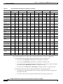
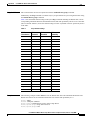
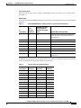
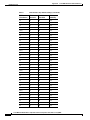
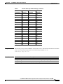
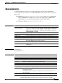
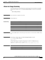
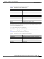
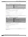
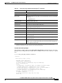
IP Multicast Address Scoping
The multicast address range is subdivided to provide predictable behavior for various address ranges and
for address reuse within smaller domains. Table 1 is a summary of the multicast address ranges. A brief
summary description of each range follows.
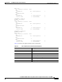
Table 1
Multicast Address Range Assignments
Name
Range
Description
Reserved Link-Local Addresses
224.0.0.0 to 224.0.0.255
Reserved for use by network protocols on a local network
segment.
Globally Scoped Addresses
224.0.1.0 to
238.255.255.255
Reserved to send multicast data between organizations and
across the Internet.
Source Specific Multicast
232.0.0.0 to
232.255.255.255
Reserved for use with the SSM datagram delivery model
where data is forwarded only to receivers that have
explicitly joined the group.
GLOP Addresses
233.0.0.0 to
233.255.255.255
Reserved for statically defined addresses by organizations
that already have an assigned autonomous system (AS)
domain number.
Limited Scope Address
239.0.0.0 to
239.255.255.255
Reserved as administratively or limited scope addresses for
use in private multicast domains.
Reserved Link-Local Addresses
The IANA has reserved the range 224.0.0.0 to 224.0.0.255 for use by network protocols on a local
network segment. Packets with an address in this range are local in scope and are not forwarded by IP
routers. Packets with link local destination addresses are typically sent with a time-to-live (TTL) value
of 1 and are not forwarded by a router.
Within this range, reserved link-local addresses provide network protocol functions for which they are
reserved. Network protocols use these addresses for automatic router discovery and to communicate
important routing information. For example, Open Shortest Path First (OSPF) uses the IP addresses
224.0.0.5 and 224.0.0.6 to exchange link-state information.
IANA assigns single multicast address requests for network protocols or network applications out of the
224.0.1.xxx address range. Multicast routers forward these multicast addresses.
Globally Scoped Addresses
Addresses in the range 224.0.1.0 to 238.255.255.255 are called globally scoped addresses. These
addresses are used to send multicast data between organizations across the Internet. Some of these
addresses have been reserved by IANA for use by multicast applications. For example, the IP address
224.0.1.1 is reserved for Network Time Protocol (NTP).
Source Specific Multicast Addresses
Addresses in the range 232.0.0.0/8 are reserved for Source Specific Multicast (SSM) by IANA. In
Cisco IOS software, you can use the ip pim ssm command to configure SSM for arbitrary IP multicast
addresses also. SSM is an extension of Protocol Independent Multicast (PIM) that allows for an efficient
data delivery mechanism in one-to-many communications. SSM is described in the “IP Multicast
Delivery Modes” section on page 1-22.
Cisco MWR 2941 Mobile Wireless Edge Router Software Configuration Guide, Release 12.2(33)MRB
OL-21227-02
1-21
Chapter 1
Cisco MWR 2941 Router Overview
Features
GLOP Addresses
GLOP addressing (as proposed by RFC 2770, GLOP Addressing in 233/8) proposes that the 233.0.0.0/8
range be reserved for statically defined addresses by organizations that already have an AS number
reserved. This practice is called GLOP addressing. The AS number of the domain is embedded into the
second and third octets of the 233.0.0.0/8 address range. For example, AS 62010 is written in
hexadecimal format as F23A. Separating the two octets F2 and 3A results in 242 and 58 in decimal
format. These values result in a subnet of 233.242.58.0/24 that would be globally reserved for AS 62010
to use.
Limited Scope Addresses
The range 239.0.0.0 to 239.255.255.255 is reserved as administratively or limited scoped addresses for
use in private multicast domains. These addresses are constrained to a local group or organization.
Companies, universities, and other organizations can use limited scope addresses to have local multicast
applications that will not be forwarded outside their domain. Routers typically are configured with filters
to prevent multicast traffic in this address range from flowing outside an autonomous system (AS) or
any user-defined domain. Within an AS or domain, the limited scope address range can be further
subdivided so that local multicast boundaries can be defined.
Note
Network administrators may use multicast addresses in this range, inside a domain, without conflicting
with others elsewhere in the Internet.
Layer 2 Multicast Addresses
Historically, network interface cards (NICs) on a LAN segment could receive only packets destined for
their burned-in MAC address or the broadcast MAC address. In IP multicast, several hosts need to be
able to receive a single data stream with a common destination MAC address. Some means had to be
devised so that multiple hosts could receive the same packet and still be able to differentiate between
several multicast groups. One method to accomplish this is to map IP multicast Class D addresses
directly to a MAC address. Using this method, NICs can receive packets destined to many different
MAC address.
Cisco Group Management Protocol (CGMP) is used on routers connected to Catalyst switches to
perform tasks similar to those performed by IGMP. CGMP is necessary for those Catalyst switches that
cannot distinguish between IP multicast data packets and IGMP report messages, both of which are
addressed to the same group address at the MAC level.
IP Multicast Delivery Modes
IP multicast delivery modes differ only for the receiver hosts, not for the source hosts. A source host
sends IP multicast packets with its own IP address as the IP source address of the packet and a group
address as the IP destination address of the packet.
Any Source Multicast
For the Any Source Multicast (ASM) delivery mode, an IP multicast receiver host can use any version
of IGMP to join a multicast group. This group is notated as G in the routing table state notation. By
joining this group, the receiver host is indicating that it wants to receive IP multicast traffic sent by any
source to group G. The network will deliver IP multicast packets from any source host with the
destination address G to all receiver hosts in the network that have joined group G.
Cisco MWR 2941 Mobile Wireless Edge Router Software Configuration Guide, Release 12.2(33)MRB
1-22
OL-21227-02
Chapter 1
Cisco MWR 2941 Router Overview
Features
ASM requires group address allocation within the network. At any given time, an ASM group should
only be used by a single application. When two applications use the same ASM group simultaneously,
receiver hosts of both applications will receive traffic from both application sources. This may result in
unexpected excess traffic in the network. This situation may cause congestion of network links and
malfunction of the application receiver hosts.
Note
Release 12.2(33)MRB does not support Any Source Multicast.
Source Specific Multicast
Source Specific Multicast (SSM) is a datagram delivery model that best supports one-to-many
applications, also known as broadcast applications. SSM is a core network technology for the Cisco
implementation of IP multicast targeted for audio and video broadcast application environments and is
described in RFC 3569. Source specific multicast consists of
•
Protocol Independent Multicast source-specific mode (PIM-SSM)
•
Internet Group Management Protocol Version 3 (IGMPv3)
For the SSM delivery mode, an IP multicast receiver host must use IGMP Version 3 (IGMPv3) to
subscribe to channel (S,G). By subscribing to this channel, the receiver host is indicating that it wants
to receive IP multicast traffic sent by source host S to group G. The network will deliver IP multicast
packets from source host S to group G to all hosts in the network that have subscribed to the channel
(S, G).
SSM does not require group address allocation within the network, only within each source host.
Different applications running on the same source host must use different SSM groups. Different
applications running on different source hosts can arbitrarily reuse SSM group addresses without
causing any excess traffic on the network.
Protocol Independent Multicast
The Protocol Independent Multicast (PIM) protocol maintains the current IP multicast service mode of
receiver-initiated membership. PIM is not dependent on a specific unicast routing protocol; it is IP
routing protocol independent and can leverage whichever unicast routing protocols are used to populate
the unicast routing table, including Open Shortest Path First (OSPF), Border Gateway Protocol (BGP),
and static routes. PIM uses unicast routing information to perform the multicast forwarding function.
Although PIM is called a multicast routing protocol, it actually uses the unicast routing table to perform
the reverse path forwarding (RPF) check function instead of building up a completely independent
multicast routing table. Unlike other routing protocols, PIM does not send and receive routing updates
between routers.
PIM is defined in RFC 2362, Protocol-Independent Multicast-Sparse Mode (PIM-SM): Protocol
Specification.
Cisco MWR 2941 Mobile Wireless Edge Router Software Configuration Guide, Release 12.2(33)MRB
OL-21227-02
1-23
Chapter 1
Cisco MWR 2941 Router Overview
Features
PIM Modes
Cisco IOS defines the following PIM modes:
•
PIM Dense Mode—Uses a push model to flood multicast traffic to every corner of the network. This
push model is a method for delivering data to the receivers without the receivers requesting the data.
This method is efficient in certain deployments in which there are active receivers on every subnet
in the network. Dense mode is not supported in Release 12.2(33)MRB.
•
PIM Sparse Mode—Uses a pull model to deliver multicast traffic. Only network segments with
active receivers that have explicitly requested the data will receive the traffic. PIM sparse mode is
supported in Release 12.2(33)MRB.
•
Sparse-Dense Mode—PIM runs sparse and dense mode according to the group mode; the interface
is treated as dense mode if the group is in dense mode; the interface is treated in sparse mode if the
group is in sparse mode. Sparse-dense mode is supported in Release 12.2(33)MRB.
•
Bidirectional PIM—Traffic is routed only along a bidirectional shared tree that is rooted at the RP
for the group. In bidir-PIM, the IP address of the RP acts as the key to having all routers establish a
loop-free spanning tree topology rooted in that IP address. Bidirectional PIM is not supported in
Release 12.2(33)MRB.
For more information about PIM modes, see the Cisco IOS IP Multicast Configuration Guide, Release
12.2SR.
Multicast Group Modes
In PIM, packet traffic for a multicast group is routed according to the rules of the mode configured for
that multicast group. Cisco IOS supports four modes for a multicast group:
•
PIM Bidirectional mode—Traffic is routed only along a bidirectional shared tree that is rooted at
the rendezvous point (RP) for the group.
•
PIM Sparse mode—Uses a unidirectional shared tree whose root node is called the rendezvous point
(RP).
•
PIM Dense mode—Dense mode operates using the broadcast (flood) and prune model.
•
PIM Source Specific Multicast (SSM) mode—Datagram traffic is forwarded to receivers from only
those multicast sources that the receivers have explicitly joined.
The MWR 2941 supports PIM Sparse mode and PIM SSM mode.
Sparse Mode
Sparse mode operation centers around a single unidirectional shared tree whose root node is called the
rendezvous point (RP). Sources must register with the RP to get their multicast traffic to flow down the
shared tree by way of the RP. This registration process actually triggers a shortest path tree (SPT) Join
by the RP toward the source when there are active receivers for the group in the network.
A sparse mode group uses the explicit join model of interaction. Receiver hosts join a group at a
rendezvous point (RP). Different groups can have different RPs.
Multicast traffic packets flow down the shared tree to only those receivers that have explicitly asked to
receive the traffic.
Note
The Cisco MWR 2941 supports sparse mode with a single static Rendezvous Point.
Cisco MWR 2941 Mobile Wireless Edge Router Software Configuration Guide, Release 12.2(33)MRB
1-24
OL-21227-02
Chapter 1
Cisco MWR 2941 Router Overview
Features
For more information about sparse mode, see the Cisco IOS IP Multicast Configuration Guide, Release
12.2SR.
PIM Source Specific Multicast Mode
SSM is a datagram delivery model that best supports one-to-many applications, also known as broadcast
applications. SSM is a core networking technology for the Cisco implementation of IP multicast
solutions targeted for audio and video broadcast application environments and is described in RFC 3569.
The following two Cisco IOS components together support the implementation of SSM:
•
Protocol Independent Multicast source-specific mode (PIM-SSM)
•
Internet Group Management Protocol Version 3 (IGMPv3)
Protocol Independent Multicast (PIM) SSM, or PIM-SSM, is the routing protocol that supports the
implementation of SSM and is derived from PIM sparse mode (PIM-SM). IGMP is the Internet
Engineering Task Force (IETF) standards track protocol used for hosts to signal multicast group
membership to routers. IGMP Version 3 supports source filtering, which is required for SSM. For SSM
to run with IGMPv3, SSM must be supported in the Cisco IOS router, the host where the application is
running, and the application itself.
For more information about SSM, see the Cisco IOS IP Multicast Configuration Guide, Release 12.2SR.
Rendezvous Points
A rendezvous point (RP) is a role that a router performs when operating in PIM-SM mode. An RP is
required only in networks running PIM-SM. In PIM-SM, only network segments with active receivers
that have explicitly requested multicast data will be forwarded the traffic. This method of delivering
multicast data is in contrast to the PIM dense mode (PIM-DM) model. In PIM-DM, multicast traffic is
initially flooded to all segments of the network. Routers that have no downstream neighbors or directly
connected receivers prune back the unwanted traffic.
An RP acts as the meeting place for sources and receivers of multicast data. In a PIM-SM network,
sources must send their traffic to the RP. This traffic is then forwarded to receivers down a shared
distribution tree. By default, when the first hop router of the receiver learns about the source, it will send
a Join message directly to the source, creating a source-based distribution tree from the source to the
receiver. This source tree does not include the RP unless the RP is located within the shortest path
between the source and receiver.
In most cases, the placement of the RP in the network is not a complex decision. By default, the RP is
needed only to start new sessions with sources and receivers. Consequently, the RP experiences little
overhead from traffic flow or processing. In PIM version 2, the RP performs less processing than in PIM
version 1 because sources must only periodically register with the RP to create state.
Auto-RP
In the first version of PIM-SM, all leaf routers (routers directly connected to sources or receivers) were
required to be manually configured with the IP address of the RP. This type of configuration is also
known as static RP configuration. Configuring static RPs is relatively easy in a small network, but it can
be laborious in a large, complex network.
Following the introduction of PIM-SM version 1, Cisco implemented a version of PIM-SM with the
Auto-RP feature. Auto-RP automates the distribution of group-to-RP mappings in a PIM network.
Auto-RP has the following benefits:
•
Configuring the use of multiple RPs within a network to serve different groups is easy.
Cisco MWR 2941 Mobile Wireless Edge Router Software Configuration Guide, Release 12.2(33)MRB
OL-21227-02
1-25
Chapter 1
Cisco MWR 2941 Router Overview
Features
•
Auto-RP allows load splitting among different RPs and arrangement of RPs according to the
location of group participants.
•
Auto-RP avoids inconsistent, manual RP configurations that can cause connectivity problems.
Multiple RPs can be used to serve different group ranges or serve as backups to each other. For Auto-RP
to work, a router must be designated as an RP-mapping agent, which receives the RP-announcement
messages from the RPs and arbitrates conflicts. The RP-mapping agent then sends the consistent
group-to-RP mappings to all other routers. Thus, all routers automatically discover which RP to use for
the groups they support.
Note
If you configure PIM in sparse mode or sparse-dense mode and do not configure Auto-RP, you must
statically configure an RP.
Note
If router interfaces are configured in sparse mode, Auto-RP can still be used if all routers are configured
with a static RP address for the Auto-RP groups.
To make Auto-RP work, a router must be designated as an RP mapping agent, which receives the RP
announcement messages from the RPs and arbitrates conflicts. The RP mapping agent then sends the
consistent group-to-RP mappings to all other routers by dense mode flooding. Thus, all routers
automatically discover which RP to use for the groups they support. The Internet Assigned Numbers
Authority (IANA) has assigned two group addresses, 224.0.1.39 and 224.0.1.40, for Auto-RP. One
advantage of Auto-RP is that any change to the RP designation must be configured only on the routers
that are RPs and not on the leaf routers. Another advantage of Auto-RP is that it offers the ability to
scope the RP address within a domain. Scoping can be achieved by defining the time-to-live (TTL) value
allowed for the Auto-RP advertisements.
Each method for configuring an RP has its own strengths, weaknesses, and level of complexity. In
conventional IP multicast network scenarios, we recommend using Auto-RP to configure RPs because
it is easy to configure, well-tested, and stable. The alternative ways to configure an RP are static RP,
Auto-RP, and bootstrap router.
Bootstrap Router
Another RP selection model called bootstrap router (BSR) was introduced after Auto-RP in PIM-SM
version 2. BSR performs similarly to Auto-RP in that it uses candidate routers for the RP function and
for relaying the RP information for a group. RP information is distributed through BSR messages, which
are carried within PIM messages. PIM messages are link-local multicast messages that travel from PIM
router to PIM router. Because of this single hop method of disseminating RP information, TTL scoping
cannot be used with BSR. A BSR performs similarly as an RP, except that it does not run the risk of
reverting to dense mode operation, and it does not offer the ability to scope within a domain.
Multicast Source Discovery Protocol
In the PIM sparse mode model, multicast sources and receivers must register with their local rendezvous
point (RP). Actually, the router closest to a source or a receiver registers with the RP, but the key point
to note is that the RP “knows” about all the sources and receivers for any particular group. RPs in other
domains have no way of knowing about sources that are located in other domains. Multicast Source
Discovery Protocol (MSDP) is an elegant way to solve this problem.
MSDP is a mechanism that allows RPs to share information about active sources. RPs know about the
receivers in their local domain. When RPs in remote domains hear about the active sources, they can
pass on that information to their local receivers. Multicast data can then be forwarded between the
Cisco MWR 2941 Mobile Wireless Edge Router Software Configuration Guide, Release 12.2(33)MRB
1-26
OL-21227-02
Chapter 1
Cisco MWR 2941 Router Overview
Features
domains. A useful feature of MSDP is that it allows each domain to maintain an independent RP that
does not rely on other domains, but it does enable RPs to forward traffic between domains. PIM-SM is
used to forward the traffic between the multicast domains.
The RP in each domain establishes an MSDP peering session using a TCP connection with the RPs in
other domains or with border routers leading to the other domains. When the RP learns about a new
multicast source within its own domain (through the normal PIM register mechanism), the RP
encapsulates the first data packet in a Source-Active (SA) message and sends the SA to all MSDP peers.
Each receiving peer uses a modified Reverse Path Forwarding (RPF) check to forward the SA, until the
SA reaches every MSDP router in the interconnected networks—theoretically the entire multicast
internet. If the receiving MSDP peer is an RP, and the RP has a (*, G) entry for the group in the SA (there
is an interested receiver), the RP creates (S,G) state for the source and joins to the shortest path tree for
the source. The encapsulated data is decapsulated and forwarded down the shared tree of that RP. When
the last hop router (the router closest to the receiver) receives the multicast packet, it may join the
shortest path tree to the source. The MSDP speaker periodically sends SAs that include all sources within
the domain of the RP.
MSDP was developed for peering between Internet service providers (ISPs). ISPs did not want to rely
on an RP maintained by a competing ISP to provide service to their customers. MSDP allows each ISP
to have its own local RP and still forward and receive multicast traffic to the Internet.
Anycast RP
Anycast RP is a useful application of MSDP. Originally developed for interdomain multicast
applications, MSDP used for Anycast RP is an intradomain feature that provides redundancy and
load-sharing capabilities. Enterprise customers typically use Anycast RP for configuring a Protocol
Independent Multicast sparse mode (PIM-SM) network to meet fault tolerance requirements within a
single multicast domain.
In Anycast RP, two or more RPs are configured with the same IP address on loopback interfaces. The
Anycast RP loopback address should be configured with a 32-bit mask, making it a host address. All the
downstream routers should be configured to “know” that the Anycast RP loopback address is the IP
address of their local RP. IP routing automatically will select the topologically closest RP for each
source and receiver. Assuming that the sources are evenly spaced around the network, an equal number
of sources will register with each RP. That is, the process of registering the sources will be shared
equally by all the RPs in the network.
Because a source may register with one RP and receivers may join to a different RP, a method is needed
for the RPs to exchange information about active sources. This information exchange is done with
MSDP.
In Anycast RP, all the RPs are configured to be MSDP peers of each other. When a source registers with
one RP, an SA message will be sent to the other RPs informing them that there is an active source for a
particular multicast group. The result is that each RP will know about the active sources in the area of
the other RPs. If any of the RPs were to fail, IP routing would converge and one of the RPs would
become the active RP in more than one area. New sources would register with the backup RP. Receivers
would join toward the new RP and connectivity would be maintained.
Note
The RP is normally needed only to start new sessions with sources and receivers. The RP facilitates the
shared tree so that sources and receivers can directly establish a multicast data flow. If a multicast data
flow is already directly established between a source and the receiver, then an RP failure will not affect
that session. Anycast RP ensures that new sessions with sources and receivers can begin at any time.
Cisco MWR 2941 Mobile Wireless Edge Router Software Configuration Guide, Release 12.2(33)MRB
OL-21227-02
1-27
Chapter 1
Cisco MWR 2941 Router Overview
Features
Multicast Forwarding
Forwarding of multicast traffic is accomplished by multicast-capable routers. These routers create
distribution trees that control the path that IP multicast traffic takes through the network in order to
deliver traffic to all receivers.
Multicast traffic flows from the source to the multicast group over a distribution tree that connects all of
the sources to all of the receivers in the group. This tree may be shared by all sources (a shared tree) or
a separate distribution tree can be built for each source (a source tree). The shared tree may be one-way
or bidirectional.
Before describing the structure of source and shared trees, it is helpful to explain the notations that are
used in multicast routing tables. These notations include the following:
•
(S,G) = (unicast source for the multicast group G, multicast group G)
•
(*,G) = (any source for the multicast group G, multicast group G)
The notation of (S,G), pronounced “S comma G,” enumerates a shortest path tree where S is the IP
address of the source and G is the multicast group address.
Shared trees are (*,G) and the source trees are (S,G) and always routed at the sources.
Multicast Distribution Source Tree (Shortest Path Tree)
The simplest form of a multicast distribution tree is a source tree. A source tree has its root at the source
host and has branches forming a spanning tree through the network to the receivers. Because this tree
uses the shortest path through the network, it is also referred to as a shortest path tree (SPT).
Figure 7 shows an example of an SPT for group 224.1.1.1 rooted at the source, Host A, and connecting
two receivers, Hosts B and C.
Source Tree
Source
Host A
Notation: (S, G)
S = source
G = group
192.168.1.1
224.1.1.1 traffic
A
B
C
192.168.2.2
Receiver
Host B
D
F
E
192.168.3.3
Host C
Receiver
121932
Figure 7
Using standard notation, the SPT for the example shown in Figure 7 would be (192.168.1.1, 224.1.1.1).
The (S,G) notation implies that a separate SPT exists for each individual source sending to each
group—which is correct.
Cisco MWR 2941 Mobile Wireless Edge Router Software Configuration Guide, Release 12.2(33)MRB
1-28
OL-21227-02
Chapter 1
Cisco MWR 2941 Router Overview
Features
Multicast Distribution Shared Tree
Unlike source trees that have their root at the source, shared trees use a single common root placed at
some chosen point in the network. This shared root is called a rendezvous point (RP).
Figure 8 shows a shared tree for the group 224.2.2.2 with the root located at Router D. This shared tree
is unidirectional. Source traffic is sent towards the RP on a source tree. The traffic is then forwarded
down the shared tree from the RP to reach all of the receivers (unless the receiver is located between the
source and the RP, in which case it will be serviced directly).
Shared Distribution Tree
Source 1
Host A
Notation: (*, G)
* = all sources
G = group
192.168.1.1
224.2.2.2 traffic
Source 2
A
B
C
192.168.2.2
Receiver
Host B
D
Rendezvous
Point
F
Host D
192.168.4.4
E
192.168.3.3
Host C
Receiver
121933
Figure 8
In this example, multicast traffic from the sources, Hosts A and D, travels to the root (Router D) and
then down the shared tree to the two receivers, Hosts B and C. Because all sources in the multicast group
use a common shared tree, a wildcard notation written as (*, G), pronounced “star comma G,” represents
the tree. In this case, * means all sources, and G represents the multicast group. Therefore, the shared
tree shown in Figure 8 would be written as (*, 224.2.2.2).
Both source trees and shared trees are loop-free. Messages are replicated only where the tree branches.
Members of multicast groups can join or leave at any time; therefore the distribution trees must be
dynamically updated. When all the active receivers on a particular branch stop requesting the traffic for
a particular multicast group, the routers prune that branch from the distribution tree and stop forwarding
traffic down that branch. If one receiver on that branch becomes active and requests the multicast traffic,
the router will dynamically modify the distribution tree and start forwarding traffic again.
Source Tree Advantage
Source trees have the advantage of creating the optimal path between the source and the receivers. This
advantage guarantees the minimum amount of network latency for forwarding multicast traffic.
However, this optimization comes at a cost. The routers must maintain path information for each source.
In a network that has thousands of sources and thousands of groups, this overhead can quickly become
a resource issue on the routers. Memory consumption from the size of the multicast routing table is a
factor that network designers must take into consideration.
Cisco MWR 2941 Mobile Wireless Edge Router Software Configuration Guide, Release 12.2(33)MRB
OL-21227-02
1-29
Chapter 1
Cisco MWR 2941 Router Overview
Features
Shared Tree Advantage
Shared trees have the advantage of requiring the minimum amount of state in each router. This advantage
lowers the overall memory requirements for a network that only allows shared trees. The disadvantage
of shared trees is that under certain circumstances the paths between the source and receivers might not
be the optimal paths, which might introduce some latency in packet delivery. For example, in Figure 8
the shortest path between Host A (source 1) and Host B (a receiver) would be Router A and Router C.
Because we are using Router D as the root for a shared tree, the traffic must traverse Routers A, B, D
and then C. Network designers must carefully consider the placement of the rendezvous point (RP) when
implementing a shared tree-only environment.
In unicast routing, traffic is routed through the network along a single path from the source to the
destination host. A unicast router does not consider the source address; it considers only the destination
address and how to forward the traffic toward that destination. The router scans through its routing table
for the destination address and then forwards a single copy of the unicast packet out the correct interface
in the direction of the destination.
In multicast forwarding, the source is sending traffic to an arbitrary group of hosts that are represented
by a multicast group address. The multicast router must determine which direction is the upstream
direction (toward the source) and which one is the downstream direction (or directions) toward the
receivers. If there are multiple downstream paths, the router replicates the packet and forwards it down
the appropriate downstream paths (best unicast route metric)—which is not necessarily all paths.
Forwarding multicast traffic away from the source, rather than to the receiver, is called Reverse Path
Forwarding (RPF). RPF is described in the following section.
Reverse Path Forwarding (RPF)
In unicast routing, traffic is routed through the network along a single path from the source to the
destination host. A unicast router does not consider the source address; it considers only the destination
address and how to forward the traffic toward that destination. The router scans through its routing table
for the destination network and then forwards a single copy of the unicast packet out the correct interface
in the direction of the destination.
In multicast forwarding, the source is sending traffic to an arbitrary group of hosts that are represented
by a multicast group address. The multicast router must determine which direction is the upstream
direction (toward the source) and which one is the downstream direction (or directions) toward the
receivers. If there are multiple downstream paths, the router replicates the packet and forwards it down
the appropriate downstream paths (best unicast route metric)—which is not necessarily all paths.
Forwarding multicast traffic away from the source, rather than to the receiver, is called Reverse Path
Forwarding (RPF). RPF is an algorithm used for forwarding multicast datagrams.
Protocol Independent Multicast (PIM) uses the unicast routing information to create a distribution tree
along the reverse path from the receivers towards the source. The multicast routers then forward packets
along the distribution tree from the source to the receivers. RPF is a key concept in multicast forwarding.
It enables routers to correctly forward multicast traffic down the distribution tree. RPF makes use of the
existing unicast routing table to determine the upstream and downstream neighbors. A router will
forward a multicast packet only if it is received on the upstream interface. This RPF check helps to
guarantee that the distribution tree will be loop-free.
Cisco MWR 2941 Mobile Wireless Edge Router Software Configuration Guide, Release 12.2(33)MRB
1-30
OL-21227-02
Chapter 1
Cisco MWR 2941 Router Overview
Features
RPF Check
When a multicast packet arrives at a router, the router performs an RPF check on the packet. If the RPF
check succeeds, the packet is forwarded. Otherwise, it is dropped.
For traffic flowing down a source tree, the RPF check procedure works as follows:
1.
The router looks up the source address in the unicast routing table to determine if the packet has
arrived on the interface that is on the reverse path back to the source.
2.
If the packet has arrived on the interface leading back to the source, the RPF check succeeds and the
packet is forwarded out the interfaces present in the outgoing interface list of a multicast routing
table entry.
3.
If the RPF check in Step 2 fails, the packet is dropped.
Figure 9 shows an example of an unsuccessful RPF check.
Figure 9
RPF Check Fails
Multicast packet from
source 151.10.3.21
Multicast Route Table
Interface
151.10.0.0/16
198.14.32.0/24
204.1.16.0/24
S1
S0
E0
RPF Check Fails
S0
S1
Packet arrived on
wrong interface.
Discard packet.
S2
121934
Network
E0
As Figure 9 illustrates, a multicast packet from source 151.10.3.21 is received on serial interface 0 (S0).
A check of the unicast route table shows that S1 is the interface this router would use to forward unicast
data to 151.10.3.21. Because the packet has arrived on interface S0, the packet is discarded.
Figure 10 shows an example of a successful RPF check.
Figure 10
RPF Check Succeeds
Multicast packet from
source 151.10.3.21
Multicast Route Table
Interface
151.10.0.0/16
198.14.32.0/24
204.1.16.0/24
S1
S0
E0
S0
Packet arrived on
correct interface.
S1
S2
RPF Check
Succeeds
E0
121935
Network
In this example, the multicast packet has arrived on interface S1. The router refers to the unicast routing
table and finds that S1 is the correct interface. The RPF check passes, and the packet is forwarded.
For more information about multicast routing, see the Cisco IOS IP Multicast Configuration Guide,
Release 12.2SR. For instructions on how to configure multicast routing, see the “Configuring IP
Multicast” section on page 4-64.
Cisco MWR 2941 Mobile Wireless Edge Router Software Configuration Guide, Release 12.2(33)MRB
OL-21227-02
1-31
Chapter 1
Cisco MWR 2941 Router Overview
Features
MLPPP Optimization Features
The Cisco MWR 2941 supports several features that improve the performance of Multilink
Point-to-Point Protocol (MLPPP) connections and related applications such as PWE3 over MLPPP and
IP over MLPPP.
Distributed Multilink Point-to-Point Protocol (dMLPPP) Offload
Distributed Multilink Point-to-Point Protocol (dMLPPP) allows you to combine T1 or E1 connections
into a bundle that has the combined bandwidth of all of the connections in the bundle, providing
improved capacity and CPU utilization over MLPPP. The dMLPPP offload feature improves the
performance for traffic in dMLPPP applications such as PWE3 over MLPPP and IP over MLPPP by
shifting processing of this traffic from the main CPU to the network processor.
The Cisco MWR 2941 supports up to four serial links per T1/E1 connection and up to 24 MLPPP
bundles. You can use the fixed T1/E1 ports to create up to 64 MLPPP links; if you install two four-port
T1/E1 HWICs, you can create up to 96 MLPPP links.
The MWR 2941 implementation of multilink (dMLPPP) uses interleaving to allow short, delay-sensitive
packets to be transmitted within a predictable amount of time. Interleaving allows the MWR 2941 to
interrupt the transmission of delay-insensitive packets in order to transmit delay-sensitive packets. You
can also adjust the responsiveness of the MWR 2941 to delay-sensitive traffic by adjusting the maximum
fragment size; this value determines the maximum delay that a delay-sensitive packet can encounter
while the MWR 2941 transmits queued fragments of delay-insensitive traffic.
Multiclass MLPPP
The MWR 2941 implementation of dMLPPP also supports Multiclass MLPPP. Multiclass MLPPP is an
extension to MLPPP functionality that allows you to divide traffic passing over a multilink bundle into
several independently sequenced streams or classes. Each multiclass MLPPP class has a unique
sequence number, and the receiving network peer processes each stream independently. The multiclass
MLPPP standard is defined in RFC 2686.
The MWR 2941 supports the following multiclass MLPPP classes:
•
Class 0–Data traffic that is subject to normal MLPPP fragmentation. Appropriate for
non-delay-sensitive traffic.
•
Class 1–Data traffic that can be interleaved but not fragmented. Appropriate for delay-sensitive
traffic such as voice.
For instructions on how to configure MLPPP backhaul, see the “Configuring MLPPP Backhaul” section
on page 4-49.
Note
The Cisco MWR 2941 does not support some PPP and MLPPP options when the bundle is offloaded to
the network processor; you can retain these options by disabling MLPPP and IPHC offloading for a
given bundle. For more information, see the “MLPPP Offload” section on page 4-58.
Note
The output for the show ppp multilink command for an offloaded MLPPP bundle differs from the
output for a non-offloaded bundle. For more information, see Appendix B, “Cisco MWR 2941 Router
Command Reference.”
Cisco MWR 2941 Mobile Wireless Edge Router Software Configuration Guide, Release 12.2(33)MRB
1-32
OL-21227-02
Chapter 1
Cisco MWR 2941 Router Overview
Features
Layer 3 Virtual Private Networks
A Virtual Private Network (VPN) is an IP-based network that delivers private network services over a
public infrastructure. VPNs allow you to create a set of sites that can communicate privately over the
Internet or other public or private networks.
A conventional VPN consists of a full mesh of tunnels or permanent virtual circuits (PVCs) connecting
all of the sites within the VPN. This type of VPN requires changes to each edge device in the VPN in
order to add a new site. Layer 3 VPNs are easier to manage and expand than conventional VPNs because
they use layer 3 communication protocols and are based on a peer model. The peer model enables the
service provider and customer to exchange Layer 3 routing information, enabling service providers to
relay data between customer sites without customer involvement. The peer model also provides
improved security of data transmission between VPN sites because data is isolated between improves
security between VPN sites.
The Cisco MWR 2941 supports the following MPLS VPN types:
•
Basic Layer 3 VPN—Provides a VPN private tunnel connection between customer edge (CE)
devices in the service provider network. The provider edge (PE) router uses Multiprotocol Border
Gateway Protocol (MP-BGP) to distribute VPN routes and MPLS Label Distribution Protocol
(LDP) to distribute Interior Gateway Protocol (IGP) labels to the next-hop PE router.
•
MPLS Carrier Supporting Carrier (CSC) VPN—Enables an MPLS VPN-based service provider to
allow other service providers to use a segment of its backbone network. MPLS CSC VPNs use
MPLS LDP to distribute MPLS labels and IGP to distribute routes.
•
Inter-Autonomous System (AS) VPN—An inter-AS VPN allows service providers running separate
networks to jointly offer MPLS VPN services to the same end customer; an inter-AS VPN can begin
at one customer site and traverse multiple service provider backbones before arriving at another
customer site.
For instructions on how to configure an layer 3 VPN, see the “Layer 3 Virtual Private Networks” section
on page 1-33.
Intelligent Cell Site IP Services
The Cisco RAN-O and IP-RAN solutions allow you to deliver profit-enhancing services. This is
achieved through the set of IP networking features supported in Cisco IOS software that extends to the
cell site (see Figure 1-11 on page 1-34).
Cell Site Points-of-Presence
The cell site becomes a physical Point-of-Presence (POP) from which to offer hotspot services, or voice
and wired ISP services, to nearby enterprises and residences. Because many cell sites are located in and
around downtown areas, hotels, airports, and convention centers, they make attractive sites for
co-locating public wireless LAN (PWLAN) access points and other wireless data overlays. Many of
these wireless data radios are IP-based. IP networking features, like Mobile IP, VoIP, IP Multicast, VPN,
and content caching, enable delivery of new revenue-generating services over these radios. The
corresponding traffic “rides for free” on the spare backhaul bandwidth made available by Cisco Abis
solutions (see Figure 1-11).
Cisco MWR 2941 Mobile Wireless Edge Router Software Configuration Guide, Release 12.2(33)MRB
OL-21227-02
1-33
Chapter 1
Cisco MWR 2941 Router Overview
Features
Figure 1-11
Cisco MWR 2941 Router in a Cell Site POP—Example
GSM BTS
IP-PBX
BSC
TDM
TDM
Cisco
MWR
100/1000 Ethernet
Cisco 7600
Series Router
T1/E1/Ethernet/xDSL
IP-PBX
Abis/lub over IP
PWLAN
WCDMA-TDD
WiMAX
(802.16/20)
IP
UMTS Node B
(R4/R99)
HSDPA
UMTS Node B
(RS/R6)
Cell site
Mobile IP/FA
VoIP
Content Caching
Multi VPN
IP Multicasting
QoS
PPP
DHCP
Routing
Access network
IP
Cisco
mobile
exchange
RNC
253153
ATM
ATM
BSC/RNC site
Mobile
Internet
edge
Quality of Service
This section describes the Quality of Service (QoS) features on the Cisco MWR 2941. The
Cisco MWR 2941 supports the following QoS features:
Note
•
Traffic Classification
•
Traffic Marking
•
Traffic Queuing
•
Traffic Shaping
The Cisco MWR 2941 support for QoS varies based on the interface and traffic type. For more
information about the QoS limitations, see the “Configuring Quality of Service (QoS)” section on
page 4-88.
For instructions on how to configure QoS on the Cisco MWR 2941, see the “Configuring Quality of
Service (QoS)” section on page 4-88.
Cisco MWR 2941 Mobile Wireless Edge Router Software Configuration Guide, Release 12.2(33)MRB
1-34
OL-21227-02
Chapter 1
Cisco MWR 2941 Router Overview
Network Management Features
Traffic Classification
Classifying network traffic allows you to organize packets into traffic classes based on whether the
traffic matches specific criteria. Classifying network traffic is the foundation for enabling many QoS
features on your network. For instructions on how to configure traffic classification, see the
“Configuring Classification” section on page 4-95.
Traffic Marking
Marking network traffic allows you to set or modify the attributes for packets in a defined traffic class.
You can use marking with traffic classification to configure variety of QoS features for your network.
For instructions on how to configure traffic marking, see the “Configuring Marking” section on
page 4-97.
Traffic Queuing
The Cisco MWR 2941 supports class-based WFQ (CBWFQ) for congestion management. CBWFQ
extends the standard WFQ functionality to provide support for user-defined traffic classes. For CBWFQ,
you define traffic classes based on match criteria such as input interface. Packets satisfying the match
criteria for a class constitute the traffic for that class. For more instructions on how to configure traffic
queuing, see the “Configuring Congestion Management” section on page 4-101.
Traffic Shaping
Regulating the packet flow on the network is also known as traffic shaping. Traffic shaping allows you
to control the speed of traffic leaving an interface. This way, you can match the flow of the traffic to the
speed of the interface receiving the packet.
The Cisco MWR 2941 supports Class-Based Traffic Shaping. Class-Based Traffic Shaping allows you
to regulate the flow of packets leaving an interface on a per-traffic-class basis, matching the packet flow
to the speed of the interface. For more instructions on how to configure traffic shaping, see the
“Configuring Shaping” section on page 4-103.
Network Management Features
This section provides an overview of the network management features for the Cisco MWR 2941. For
more information about management features on the Cisco MWR 2941, see the “Monitoring and
Managing the Cisco MWR 2941 Router” section on page 4-107.
Cisco Mobile Wireless Transport Manager (MWTM)
You can use Cisco Mobile Wireless Transport Manager (MWTM), to monitor and manage the
Cisco MWR 2941. Cisco MWTM addresses the element-management requirements of mobile operators
and provides fault, configuration, and troubleshooting capability. For more information about MWTM,
see http://www.cisco.com/en/US/products/ps6472/tsd_products_support_series_home.html.
Cisco MWR 2941 Mobile Wireless Edge Router Software Configuration Guide, Release 12.2(33)MRB
OL-21227-02
1-35
Chapter 1
Cisco MWR 2941 Router Overview
Limitations and Restrictions
Cisco Active Network Abstraction (ANA)
You can also use Cisco Active Network Abstraction (ANA) to manage the Cisco MWR 2941. Cisco
ANA is a powerful, next-generation network resource management solution designed with a fully
distributed OSS mediation platform which abstracts the network, its topology and its capabilities from
the physical elements. Its virtual nature provides customers with a strong and reliable platform for
service activation, service assurance and network management. For more information about ANA, see
http://www.cisco.com/en/US/products/ps6776/tsd_products_support_series_home.html.
SNMP MIB Support
To view the current MIBs that the Cisco MWR 2941 supports, see the Release Notes for Cisco MWR
2941-DC Mobile Wireless Edge Router for Cisco IOS Release 12.4(20)MR.
For instructions on how to configure MIBs on the Cisco MWR 2941, see the “Configuring SNMP
Support” section on page 4-108 and the “Enabling Remote Network Management” section on
page 4-112.
Cisco Networking Services (CNS)
Cisco Networking Services (CNS) is a collection of services that can provide remote configuration of
Cisco IOS networking devices and remote execution of some command-line interface (CLI) commands.
CNS allows a Cisco MWR 2941 deployed and powered on in the field to automatically download its
configuration.
Note
The Cisco MWR 2941 only supports CNS over motherboard Ethernet interfaces. Other interface types
do not support CNS.
For instructions on how to configure CNS, see the “Configuring Cisco Networking Services (CNS)”
section on page 4-115.
Limitations and Restrictions
The following sections describe the limitations and restrictions that apply to the Cisco MWR 2941
router.
Hardware Limitations and Restrictions
To view a list of supported hardware and restrictions for the Cisco MWR 2941, see the Release Notes
for Cisco MWR 2941-DC Mobile Wireless Edge Router for Cisco IOS Release 12.2(33)MRB.
Caution
The Cisco MWR 2941 does not support online insertion and removal (OIR) of HWIC cards. Attempts
to perform OIR on a card in a powered-on router might cause damage to the card.
Cisco MWR 2941 Mobile Wireless Edge Router Software Configuration Guide, Release 12.2(33)MRB
1-36
OL-21227-02
Chapter 1
Cisco MWR 2941 Router Overview
Limitations and Restrictions
Software Limitations and Restrictions
For information about software limitations and restrictions for the Cisco MWR 2941, see the Release
Notes for Cisco MWR 2941-DC Mobile Wireless Edge Router for Cisco IOS Release 12.2(33)MRB.
Cisco MWR 2941 Mobile Wireless Edge Router Software Configuration Guide, Release 12.2(33)MRB
OL-21227-02
1-37
Chapter 1
Cisco MWR 2941 Router Overview
Limitations and Restrictions
Cisco MWR 2941 Mobile Wireless Edge Router Software Configuration Guide, Release 12.2(33)MRB
1-38
OL-21227-02
CH A P T E R
2
Cisco IOS Software Basics
This chapter provides an overview of the Cisco IOS software. Read this section before you configure the
router by using the command-line interface (CLI). This chapter includes the following topics:
•
Getting Help, page 2-1
•
Understanding Command Modes, page 2-2
•
Undoing a Command or Feature, page 2-3
•
Saving Configuration Changes, page 2-3
Understanding this information saves you time as you use the CLI. If you have never used the Cisco IOS
software or if you need a review, read this chapter before you proceed. If you are already familiar with
the Cisco IOS software, go to Chapter 3, “First-Time Configuration.”
Getting Help
Use the question mark (?) and arrow keys to help you enter commands:
•
For a list of available commands, enter a question mark:
Router> ?
•
To complete a command, enter a few known characters followed by a question mark (with no space):
Router> s?
•
For a list of command variables, enter the command followed by a space and a question mark:
Router> show ?
•
To redisplay a command that you previously entered, press the Up Arrow key. Continue to press the
Up Arrow key to see more commands.
Cisco MWR 2941 Mobile Wireless Edge Router Software Configuration Guide, Release 12.2(33)MRB
OL-21227-02
2-1
Chapter 2
Cisco IOS Software Basics
Understanding Command Modes
Understanding Command Modes
The Cisco IOS user interface is used in various command modes. Each command mode permits you to
configure different components on your router. The commands available at any given time depend on
which command mode you are in. Entering a question mark (?) at a prompt displays a list of commands
available for that command mode. The following table lists the most common command modes.
Timesaver
Command Mode
Access Method
Router Prompt
Displayed
Exit Method
User EXEC
Log in.
Router>
Use the logout command.
Privileged EXEC
From user EXEC mode, Router#
enter the enable
command.
To exit to user EXEC
mode, use the disable,
exit, or logout command.
Global configuration
From the privileged
EXEC mode, enter the
configure terminal
command.
To exit to privileged
EXEC mode, use the exit
or end command, or press
Ctrl-Z.
Interface configuration
Router (config-if)# To exit to global
From the global
configuration mode,
configuration mode, use
enter the interface type
the exit command.
number command, such
To exit directly to
as interface serial 0/0.
privileged EXEC mode,
press Ctrl-Z.
Router (config)#
Each command mode restricts you to a subset of commands. If you have trouble entering a command,
check the prompt and enter the question mark (?) to see a list of available commands. You might be in
the incorrect command mode or be using an incorrect syntax.
In the following example, notice how the prompt changes after each command to indicate a new
command mode:
Router> enable
Password: <enable password>
Router# configure terminal
Router (config)# interface serial 0/0
Router (config-if)# line 0
Router (config-line)# controller t1 0
Router (config-controller)# exit
Router (config)# exit
Router#
%SYS-5-CONFIG_I: Configured from console by console
The last message is normal and does not indicate an error. Press Return to get the Router# prompt.
Note
You can press Ctrl-Z in any mode to immediately return to enable mode (Router#), instead of entering
exit, which returns you to the previous mode.
Cisco MWR 2941 Mobile Wireless Edge Router Software Configuration Guide, Release 12.2(33)MRB
2-2
OL-21227-02
Chapter 2
Cisco IOS Software Basics
Undoing a Command or Feature
Undoing a Command or Feature
If you want to undo a command that you entered or if you want to disable a feature, enter the no keyword
before most commands; for example, no ip routing.
Saving Configuration Changes
To save your configuration changes to NVRAM, so that the changes are not lost during a system reload
or power outage, enter the copy running-config startup-config command. For example:
Router# copy running-config startup-config
Building configuration...
It might take a few minutes to save the configuration to NVRAM. After the configuration has been
saved, the following message appears:
[OK]
Router#
Cisco MWR 2941 Mobile Wireless Edge Router Software Configuration Guide, Release 12.2(33)MRB
OL-21227-02
2-3
Chapter 2
Cisco IOS Software Basics
Saving Configuration Changes
Cisco MWR 2941 Mobile Wireless Edge Router Software Configuration Guide, Release 12.2(33)MRB
2-4
OL-21227-02
CH A P T E R
3
First-Time Configuration
This chapter describes the actions to take before turning on your router for the first time. This chapter
includes the following sections:
•
Understanding the Cisco MWR 2941 Router Interface Numbering, page 3-1
•
Setup Command Facility, page 3-3
•
Configuring Global Parameters, page 3-4
•
Completing the Configuration, page 3-6
Understanding the Cisco MWR 2941 Router Interface Numbering
Each network interface on a Cisco MWR 2941 router is identified by a slot number and a port number.
Figure 3-1 shows an example of interface numbering on a Cisco MWR 2941 router:
•
Two HWIC ports (HWICs are ordered separately)
•
Two built-in Gigabit Ethernet small form-factor pluggable (SFP) interfaces (labeled GE0 and GE1)
•
Four built-in Gigabit Ethernet interfaces (labeled L2–L5)
•
16 E1/T1 ports (labeled C1AL–C15AL)
Note
The two HWIC cards shown in Figure 3-1 are not included with the Cisco MWR 2941 router; you must
order them separately.
Note
The Mini-coax timing connectors shown in Figure 3-1 only apply to the Cisco MWR 2941-DC-A router;
the Cisco MWR 2941-DC does not have these ports.
Cisco MWR 2941 Mobile Wireless Edge Router Software Configuration Guide, Release 12.2(33)MRB
OL-21227-02
3-1
Chapter 3
First-Time Configuration
Understanding the Cisco MWR 2941 Router Interface Numbering
Figure 3-1
Cisco MWR 2941 Router Port Numbers
HWIC 0 ports
1/0, 1/1, 1/2, 1/3
HWIC 1 ports
2/0, 2/1, 2/2, 2/3
16 T1/E1 ports
top row 0/1, 0/3, 0/5, 0/7,
0/9, 0/11, 0/13, 0/15
bottom row 0/0, 0/2, 0/4, 0/6,
0/8, 0/10, 0/12, 0/14
4 GE ports
0/2, 0/3, 0/4, 0/5
(RJ45 100/1000 Ethernet)
252031
Console/
Auxiliary port
2 GE ports
0/0, 0/1
(SFP 1000BT)
2 Mini-coax
connectors
10MHZ and 1PPS
BITS/SYNC
port
Slot and Port Numbering
The Cisco MWR 2941 router chassis contains the following interface types:
Note
•
16 T1/E1 ports, labeled “T1/E1”
•
4 RJ-45 jacks for copper Ethernet ports, labeled “100/1000” Ethernet
•
2 HWIC slots, labeled “HWIC0” and “HWIC1”
•
1 compact FLASH Type-II connector, labeled “Compact Flash”
•
2 SFP connectors for optical GE ports, labeled “GE0” and “GE1”
•
2 miniature coaxial connectors for 10MHZ and 1PPS timing
Miniature coaxial timing connectors are not included on all versions of the Cisco MWR 2941. You can
verify your hardware version with the VID label on the back of the router; routers labeled with a VID of
V01 or V02 do not include the timing connectors, while routers with VID V03 and higher include the
connectors.
•
1 RJ-45 connector for Console/Auxiliary, labeled “CON/AUX”
•
1 RJ-45 jack for BITS interface, labeled “BITS”
The logical slot numbers are 0 for all built-in interfaces.
The numbering format is:
Interface type Slot number/Interface number
Interface (port) numbers begin at logical 0 for each interface type.
Cisco MWR 2941 Mobile Wireless Edge Router Software Configuration Guide, Release 12.2(33)MRB
3-2
OL-21227-02
Chapter 3
First-Time Configuration
Setup Command Facility
Following is an explanation of the slot/port numbering:
•
Logical interface numbering for the built-in T1/E1 ports runs from 0/0 through 0/15. Interfaces are
hardwired; therefore, port 0 is always logical interface 0/0, port 1 is always logical interface 0/1, and
so on. Built-in T1/E1 ports are numbered bottom to top, left to right (bottom row numbered
0-2-4-6-8-10-12-14, top row numbered 1-3-5-7-9-11-13-15).
•
When the 2 HWIC slots are used to expand the T1/E1 port density to 20 or 24 ports, logical interface
numbering continues from 1/0 through 1/3 and 2/0 through 2/3. Logical interfaces for HWIC0 are
always 1/0 through 1/3 and logical interfaces for HWIC1 are always 2/0 through 2/3. Because the
interfaces are hardwired, HWIC0 port 0 is always logical interface 1/0, HWIC0 port 1 is always
logical interface 1/1, HWIC1 port 0 is always logical interface 2/0, HWIC1 port 1 is always logical
interface 2/1, and so on. Ports are numbered left to right for each HWIC.
•
Logical interface numbering for the built-in Ethernet ports runs from 0/0 through 0/5. Because the
interfaces are hard-wired, ports correspond to logical interface numbers. For example, port 0 is
always logical interface 0/0, and port 1 is always logical interface 0/1. SFP ports are numbered left
to right, 0 and 1; 100/1000 Ethernet ports are numbered left to right, 2 through 5.
Setup Command Facility
The setup command facility prompts you for information that is required to start a router functioning
quickly. The facility steps you through a basic configuration, including LAN interfaces.
If you prefer to configure the router manually or to configure a module or interface that is not included
in the setup command facility, go to Chapter 2, “Cisco IOS Software Basics.” to familiarize yourself
with the command-line interface (CLI). Then, go to Chapter 4, “Configuring the Cisco MWR 2941
Router Using the CLI.”
Note
Cisco Networking Services (CNS) is a collection of services that can provide remote configuration of
Cisco IOS networking devices and remote execution of some command-line interface (CLI) commands.
CNS allows a Cisco MWR 2941 deployed and powered on in the field to automatically download its
configuration. For more information about CNS, see the “Cisco Networking Services (CNS)” section on
page 1-36.
Before Starting Your Router
Before you power on your router and begin using the setup command facility, follow these steps:
Step 1
Set up the hardware and connect the console and network cables as described in the “Connecting Cables”
section of the Cisco MWR 2941-DC Router Hardware Installation Guide.
Step 2
Configure your PC terminal emulation program for 9600 baud, 8 data bits, no parity, and 1 stop bit.
Cisco MWR 2941 Mobile Wireless Edge Router Software Configuration Guide, Release 12.2(33)MRB
OL-21227-02
3-3
Chapter 3
First-Time Configuration
Configuring Global Parameters
Using the Setup Command Facility
The setup command facility appears in your PC terminal emulation program window. To create a basic
configuration for your router, do the following:
•
Complete the steps in the Configuring Global Parameters, page 3-4.
•
Complete the steps in the Completing the Configuration, page 3-6.
Note
If you make a mistake while using the setup command facility, you can exit the facility and run
it again. Press Ctrl-C, and type setup at the enable mode prompt (1900#).
Configuring Global Parameters
Use the following procedure to configure global parameters.
Step 1
Caution
Power on the router. Messages appear in the terminal emulation program window.
Do not press any keys on the keyboard until the messages stop. Any keys that you press during this time
are interpreted as the first command entered after the messages stop, which might cause the router to
power off and start over. Wait a few minutes. The messages stop automatically.
The messages look similar to the following:
Note
The messages vary, depending on the Cisco IOS software image and interface modules in your
router. This section is for reference only, and output might not match the messages on your
console.
rommon 1 >boot
program load complete, entry point:0x80008000, size:0xc200
Initializing ATA monitor library.......
program load complete, entry point:0x80008000, size:0xc200
Initializing ATA monitor library.......
program load complete, entry point:0x80008000, size:0xc35eec
Self decompressing the image:
############################################################################
############################################################################
############################################################################
############################################################################
############################################################################
############################################################################
############################################################################
####################### [OK]
Smart Init is enabled
smart init is sizing iomem
ID MEMORY_REQTYPE
0035C
0X005F3C00 MWR2941 Mainboard
0X000F3BB0 public buffer pools
0X00843000 public particle pools
Cisco MWR 2941 Mobile Wireless Edge Router Software Configuration Guide, Release 12.2(33)MRB
3-4
OL-21227-02
Chapter 3
First-Time Configuration
Configuring Global Parameters
TOTAL: 0X06894CB0
If any of the above Memory requirements are “UNKNOWN”, you may be using an
unsupported configuration or there is a software problem and system operation
may be compromised.
Rounded IOMEM up to: 104Mb.
Using 20 percent iomem. [104Mb/512Mb]
Restricted Rights Legend
Use, duplication, or disclosure by the Government is
subject to restrictions as set forth in subparagraph
(c) of the Commercial Computer Software - Restricted
Rights clause at FAR sec. 52.227-19 and subparagraph
(c) (1) (ii) of the Rights in Technical Data and Computer
Software clause at DFARS sec. 252.227-7013.
cisco Systems, Inc.
170 West Tasman Drive
San Jose, California 95134-1706
Cisco IOS Software, 2900 Software (MWR2900-IPRAN-M),
Experimental Version 12.4(20050412:070057),
Copyright (c) 1986-2009 by Cisco Systems, Inc.
Compiled Sat 10-Jan-09 03:19 by cbrezove
Image text-base:0x60008F60, data-base:0x6106A000
Cisco Systems, Inc. MWR-2941-DC (MPC8347E) processor (revision 0x400) with 41719
6K/107092K bytes of memory.
Processor board ID
MPC8347E CPU Rev: Part Number 0x8032, Revision ID 0x300
1 RTM Module: ASM-M2900-TOP daughter card
6 Gigabit Ethernet interfaces
1 terminal line
128K bytes of non-volatile configuration memory.
125440K bytes of ATA CompactFlash (Read/Write)
--- System Configuration Dialog --Would you like to enter the initial configuration dialog? [yes/no]: yes
At any point you may enter a question mark '?' for help.
Use ctrl-c to abort configuration dialog at any prompt.
Default settings are in square brackets '[]'.
Step 2
To begin the initial configuration dialog, enter yes when the following message appears:
Basic management setup configures only enough connectivity
for management of the system, extended setup will ask you
to configure each interface on the system
Would you like to enter basic management setup? [yes/no]: yes
Configuring global parameters:
Step 3
Enter a hostname for the router (this example uses 2941-1).
Configuring global parameters:
Enter host name [Router]: 2941-1
Step 4
Enter an enable secret password. This password is encrypted (more secure) and cannot be seen when
viewing the configuration.
The enable secret is a password used to protect access to
privileged EXEC and configuration modes. This password, after
Cisco MWR 2941 Mobile Wireless Edge Router Software Configuration Guide, Release 12.2(33)MRB
OL-21227-02
3-5
Chapter 3
First-Time Configuration
Completing the Configuration
entered, becomes encrypted in the configuration.
Enter enable secret: ciscoenable
Note
Step 5
When you enter the enable secret password, the password is visible while you type the it. After
you enter the password, it becomes encrypted in the configuration.
Enter an enable password that is different from the enable secret password. This password is not
encrypted (less secure) and can be seen when viewing the configuration.
The enable password is used when you do not specify an
enable secret password, with some older software versions, and
some boot images.
Enter enable password: ciscoenable
Step 6
To prevent unauthenticated access to the router through ports other than the console port, enter the
virtual terminal password.
The virtual terminal password is used to protect
access to the router over a network interface.
Enter virtual terminal password: ciscoterminal
Step 7
Respond to the following prompts as appropriate for your network:
Configure SNMP Network Management? [yes]:
Community string [public]: public
Step 8
The summary of interfaces appears. This list varies, depending on the network modules installed in your
router.
Current interface summary
Any interface listed with OK? value “NO” does not have a valid configuration
Interface
IP-Address
OK? Method Status
GigabitEthernet0/0 unassigned
NO unset up up
GigabitEthernet0/1 unassigned
NO unset up up
Step 9
Protocol
Specify the interface to be used to connect to the network management system.
Enter interface name used to connect to the
management network from the above interface summary: GigabitEthernet0/0
Step 10
Configure the specified interface as prompted.
Configuring interface GigabitEthernet0/0:
Configure IP on this interface? [no]:
Completing the Configuration
When you have provided all of the information prompted for by the setup command facility, the
configuration appears. Messages similar to the following appear:
The following configuration command script was created:
!
hostname 2941-1
enable secret 5 $1$5fH0$Z6Pr5EgtR5iNJ2nBg3i6y1 enable password ciscoenable line vty 0 4
Cisco MWR 2941 Mobile Wireless Edge Router Software Configuration Guide, Release 12.2(33)MRB
3-6
OL-21227-02
Chapter 3
First-Time Configuration
Completing the Configuration
password ciscoenablesnmp-server community public !
no ip routing
!
interface GigabitEthernet0/1
shutdown
!
end
To complete your router configuration, do the following:
Step 1
A setup command facility prompt you to save this configuration.
[0] Go to the IOS command prompt without saving this config.
[1] Return back to the setup without saving this config.
[2] Save this configuration to nvram and exit.
Enter your selection [2]: 2
Building configuration...
[OK]
Use the enabled mode 'configure' command to modify this configuration.
Press RETURN to get started!
If you answer:
Step 2
•
no—The configuration information that you entered is not saved, and you return to the router enable
prompt. To return to the system configuration dialog, enter setup.
•
yes—The configuration is saved, and you return to the EXEC prompt.
When the messages stop displaying in your window, press Return to view the command line prompt.
The 2941-1> prompt indicates that you are now at the CLI and you have just completed a basic router
configuration. However, this is not a complete configuration. You must configure additional parameters
by using the Cisco IOS software CLI as described in Chapter 4, “Configuring the Cisco MWR 2941
Router Using the CLI.”
Cisco MWR 2941 Mobile Wireless Edge Router Software Configuration Guide, Release 12.2(33)MRB
OL-21227-02
3-7
Chapter 3
First-Time Configuration
Completing the Configuration
Cisco MWR 2941 Mobile Wireless Edge Router Software Configuration Guide, Release 12.2(33)MRB
3-8
OL-21227-02
CH A P T E R
4
Configuring the Cisco MWR 2941 Router Using
the CLI
This chapter describes how to use the Cisco IOS software command-line interface (CLI) to configure
the the Cisco MWR 2941 Mobile Wireless Edge Router and includes the following sections:
•
Verifying the Cisco IOS Software Version, page 4-1
•
Configuration Sequence, page 4-1
•
Monitoring and Managing the Cisco MWR 2941 Router, page 4-107
For sample configurations, see Appendix A, “Sample Configurations.”
For additional configuration topics, see the Cisco IOS configuration guide and command reference
publications. These publications are available online at Cisco.com, or as printed copies that you can
order separately.
Note
Be sure to review the Chapter 2, “Cisco IOS Software Basics,” before configuring your router; it
contains important information that you need to successfully configure your router.
Verifying the Cisco IOS Software Version
To implement the Cisco MWR 2941 router, Cisco IOS Release 12.4(19)MR2 or later must be installed
on the router. To verify the version of Cisco IOS software, use the show version command.
The show version command displays the configuration of the system hardware, the software version,
the names and sources of the configuration files, and the boot images.
Configuration Sequence
The “Summary of Steps” section on page 4-2 section provides the recommended primary configuration
sequence for the Cisco MWR 2941 router. These steps have configuration substeps (or tasks) within the
primary steps or tasks.
Note
The installation of the Cisco MWR 2941 router and the Cisco T1/E1 interface card should be completed
before attempting the configuration (see the “Related Documentation” section on page xi for more
information).
Cisco MWR 2941 Mobile Wireless Edge Router Software Configuration Guide, Release 12.2(33)MRB
OL-21227-02
4-1
Chapter 4
Configuring the Cisco MWR 2941 Router Using the CLI
Configuration Sequence
The configuration sequence of the Cisco MWR 2941 router assumes that you will have already had some
familiarity with the configuration of Cisco routers. It is also assumed that you are familiar with your own
network configurations and that you are familiar with the Command Line Interface (CLI) used in
configuring Cisco routers.
Note
For correct CLI syntax and format, see the Appendix B, “Cisco MWR 2941 Router Command
Reference”.
Summary of Steps
To configure the Cisco MWR 2941 router, perform the following tasks.
1.
Configuring the Hostname and Password, page 4-2
2.
Verifying the Hostname and Password, page 4-3
3.
Configuring Gigabit Ethernet Interfaces, page 4-4
4.
Configuring Layer 2 Interfaces, page 4-6
5.
Configuring HWIC-9ESW Interfaces, page 4-11
6.
Configuring VLANs, page 4-12
7.
Configuring Resilient Ethernet Protocol (REP), page 4-15
8.
Configuring Ethernet CFM, page 4-30
9.
Configuring Ethernet Link Operations, Administration, and Maintenance (OAM), page 4-33
10. Configuring Ethernet Local Management Interface (E-LMI), page 4-38
11. Configuring Clocking and Timing, page 4-39
12. Configuring MLPPP Backhaul, page 4-49
13. Configuring Multiprotocol Label Switching (MPLS), page 4-58
14. Configuring Routing Protocols, page 4-59
15. Configuring BFD, page 4-59
16. Configuring IP Multicast, page 4-64
17. Configuring Pseudowire, page 4-73
18. Configuring Layer 3 Virtual Private Networks (VPNs), page 4-88
19. Configuring Quality of Service (QoS), page 4-88
20. Configuring Link Noise Monitor, page 4-104
21. Saving Configuration Changes, page 4-107
Configuring the Hostname and Password
Configure the hostname and set an encrypted password. Configuring a hostname allows you to
distinguish between multiple Cisco routers. Setting an encrypted password allows you to prevent
unauthorized configuration changes.
Cisco MWR 2941 Mobile Wireless Edge Router Software Configuration Guide, Release 12.2(33)MRB
4-2
OL-21227-02
Chapter 4
Configuring the Cisco MWR 2941 Router Using the CLI
Configuration Sequence
Note
In the following procedure, press the Return key after each step unless otherwise noted. At any time,
you can exit the privileged level and return to the user level by entering disable at the Router# prompt.
To configure a hostname and to set an encrypted password, follow these steps:
Step 1
Enter enable mode.
Router> enable
The Password prompt appears. Enter your password.
Password: password
When the prompt changes to Router, you have entered enable mode.
Step 2
Enter global configuration mode.
Router# configure terminal
Enter configuration commands, one per line. End with CNTL/Z.
When the prompt changes to Router(config), you have entered global configuration mode.
Router(config)#
Step 3
Change the name of the router to a meaningful name. Substitute your hostname for Router.
Router(config)# hostname Router
Router(config)#
Step 4
Enter an enable secret password. This password provides access to privileged EXEC mode. When you
type enable at the EXEC prompt (Router>), you must enter the enable secret password to access
configuration mode. Enter your secret password.
Router(config)# enable secret secret password
Step 5
Exit back to global configuration mode.
Router(config)# exit
Verifying the Hostname and Password
To verify that you have correctly configured the hostname and password, follow these steps:
Step 1
Enter the show config command.
Router# show config
Using 1888 out of 126968 bytes
!
version XX.X
.
.
.
!
hostname Router
!
Cisco MWR 2941 Mobile Wireless Edge Router Software Configuration Guide, Release 12.2(33)MRB
OL-21227-02
4-3
Chapter 4
Configuring the Cisco MWR 2941 Router Using the CLI
Configuration Sequence
enable secret 5 $1$60L4$X2JYOwoDc0.kqa1loO/w8/
.
.
.
Step 2
Check the hostname and encrypted password, which appear near the top of the command output.
Step 3
Exit global configuration mode and attempt to re-enter it using the new enable password:
Router# exit
.
.
.
Router con0 is now available
Press RETURN to get started.
Router> enable
Password: password
Router#
Configuring Gigabit Ethernet Interfaces
To configure the Gigabit Ethernet (GE) interface on the Cisco MWR 2941, complete the following tasks:
•
Configuring the Interface Properties, page 4-4
•
Setting the Speed and Duplex Mode, page 4-5
•
Enabling the Interface, page 4-6
•
Creating Backup Switch Interfaces, page 4-6
Configuring the Interface Properties
Perform a basic Gigabit Ethernet IP Address configuration by specifying the port adapter and aligning
an IP address and subnet mask of the interface as follows.
Note
In the following procedure, press the Return key after each step unless otherwise noted. At any time,
you can exit the privileged level and return to the user level by entering disable at the Router# prompt.
Note
The spanning tree-related commands described in this section are optional.
To configure the GE interface, follow these steps while in global configuration mode:
Step 1
Specify the port adapter type and the location of the interface to be configured.
Router(config)# interface gigabitethernet slot/port
Router(config-if)#
The slot is always 0 and the port is the number of the port (0 or 1).
Step 2
To set the interface type, use the switchport mode command.
Router(config-if)# switchport mode {access | trunk}
Cisco MWR 2941 Mobile Wireless Edge Router Software Configuration Guide, Release 12.2(33)MRB
4-4
OL-21227-02
Chapter 4
Configuring the Cisco MWR 2941 Router Using the CLI
Configuration Sequence
Step 3
To prioritize an interface when two bridges compete for position as the root bridge, use the spanning
tree port-priority command.
Router(config-if)# spanning-tree port-priority port_priority
Step 4
To calculate the path cost of STP on an interface, use the spanning-tree cost command.
Router(config-if)# spanning-tree cost port_cost
Step 5
For interfaces that connect to end stations, you can use the spanning-tree portfast command to set the
interface to move directly to the spanning-tree forwarding state when linkup occurs.
Router(config-if)# spanning-tree portfast
Step 6
To enable Cisco Discovery Protocol (CDP) on the router, use the cdp enable command.
Router(config-if)# cdp enable
Setting the Speed and Duplex Mode
The Gigabit Ethernet ports of the Cisco MWR 2941 router can run in full or half- duplex mode—100
Mbps or 1000 Mbps (1 Gbps). The Cisco MWR 2941 router has an autonegotiation feature that allows
the router to negotiate the speed and duplex mode with the corresponding interface at the other end of
the connection.
Autonegotiation is the default setting for the speed and transmission mode.
When you configure an interface speed and duplex mode, follow these guidelines:
•
If both ends of the line support autonegotiation, we highly recommend the use of default
autonegotiation settings.
•
When autonegotiation is turned on for either speed or duplex mode, it autonegotiates both speed and
the duplex mode.
•
If one interface supports autonegotiation, and the interface at the other end does not, configure the
duplex mode and speed on both interfaces. If you use the autonegotiation setting on the supported
side, the duplex mode setting is set at half-duplex.
Note
In the following procedure, press the Return key after each step unless otherwise noted. At any
time, you can exit the privileged level and return to the user level by entering disable at the
Router# prompt.
To configure speed and duplex operation, follow these steps while in interface configuration mode:
Step 1
Specify the duplex operation.
Router(config-if)# duplex [auto | half | full]
Step 2
Specify the speed.
Router(config-if)# speed [auto | 1000 | 100]
Cisco MWR 2941 Mobile Wireless Edge Router Software Configuration Guide, Release 12.2(33)MRB
OL-21227-02
4-5
Chapter 4
Configuring the Cisco MWR 2941 Router Using the CLI
Configuration Sequence
Enabling the Interface
Note
In the following procedure, press the Return key after each step unless otherwise noted. At any time,
you can exit the privileged level and return to the user level by entering disable at the Router# prompt.
After you configure the GE interface, enable it using the no shutdown command.by following this step
Router(config-if)# no shutdown
Creating Backup Switch Interfaces
You can use the following command to create a backup switch interface:
Router(config-if)# switchport backup interface interface_name preemption [forced |
bandwidth | off] delay [time]
For more information about this command, see switchport backup, page B-556
For instructions on how to create VLANs on GE interfaces, see Configuring VLANs, page 4-12.
Configuring Layer 2 Interfaces
The Cisco MWR 2941 has an onboard layer 2 Gigabit Ethernet switch and supports HWICs with layer
2 interfaces.To configure the layer 2 interfaces on the Cisco MWR 2941, complete the following tasks:
•
Configuring a Range of Interfaces
•
Defining a Range Macro
•
Configuring Layer 2 Optional Interface Features
Configuring a Range of Interfaces
The interface-range command allows you to configure multiple interfaces at once. Follow these steps to
configure an interface range.
Step 1
Enter enable mode.
Router> enable
Router#
Step 2
Enter configuration mode.
Router# configure terminal
Router(config)#
Step 3
Use the interface-range command to select a range on interfaces to configure. You can specify a range
that includes both VLANs and physical interfaces.
Router(config)# interface range GigabitEthernet 0/1 - 3
Cisco MWR 2941 Mobile Wireless Edge Router Software Configuration Guide, Release 12.2(33)MRB
4-6
OL-21227-02
Chapter 4
Configuring the Cisco MWR 2941 Router Using the CLI
Configuration Sequence
Defining a Range Macro
A range macro allows you to create a name that defines a range on interfaces on the Cisco MWR 2941.
Follow these steps to configure an interface range macro.
Step 1
Enter enable mode.
Router> enable
Router#
Step 2
Enter configuration mode.
Router# configure terminal
Router(config)#
Step 3
Use the interface-range command to define the macro.
Router(config)# define interface-range first_three GigabitEthernet0/1 - 2
You can use the show running-configuration command to verify the interface-range macro
configuration.
Configuring Layer 2 Optional Interface Features
•
Interface Speed and Duplex Configuration Guidelines
•
Configuring the Interface Speed
•
Configuring the Interface Duplex Mode
•
Configuring a Description for an Interface
•
Configuring a Layer 2 Interface as a Layer 2 Trunk
•
Configuring a Layer 2 Interface as Layer 2 Access
Interface Speed and Duplex Configuration Guidelines
When configuring an interface speed and duplex mode, note these guidelines:
Caution
•
Speed and duplex commands only apply to FastEthernet interfaces. They do not apply to the onboard
Gigabit Ethernet ports.
•
If both ends of the line support autonegotiation, we highly recommend the default auto negotiation
settings.
•
If one interface supports auto negotiation and the other end does not, configure duplex and speed on
both interfaces; do not use the auto setting on the supported side.
•
Both ends of the line need to be configured to the same setting; for example, both hard-set or both
auto-negotiate. Mismatched settings are not supported.
Changing the interface speed and duplex mode configuration might shut down and reenable the interface
during the reconfiguration.
Cisco MWR 2941 Mobile Wireless Edge Router Software Configuration Guide, Release 12.2(33)MRB
OL-21227-02
4-7
Chapter 4
Configuring the Cisco MWR 2941 Router Using the CLI
Configuration Sequence
Configuring the Interface Speed
Follow these steps to configure the speed of a layer 2 interface.
Step 1
Enter enable mode.
Router> enable
Router#
Step 2
Enter configuration mode.
Router# configure terminal
Router(config)#
Step 3
Enter configuration for the interface that you want to modify.
Router(config)# interface fastethernet 1/0
Step 4
Specify the interface speed. You can set an interface to 10 Mbps, 100 Mbps, or autonegotiate.
Router(config-if)# speed [10 | 100 | auto ]
Configuring the Interface Duplex Mode
Follow these steps below to set the duplex mode of a layer 2 interface.
Step 1
Enter enable mode.
Router> enable
Router#
Step 2
Enter configuration mode.
Router# configure terminal
Router(config)#
Step 3
Enter configuration for the interface that you want to modify.
Router(config)# interface fastethernet 1/1
Step 4
Use the duplex command to set the interface to send traffic at full duplex, half duplex, or to
autonegotiate its duplex setting.
Router(config-if)# duplex [auto | full | half]
You can use the show interfaces command to verify the duplex configuration.
Note
If you set the port speed to auto on a 10/100-Mbps Ethernet interface, the interface auto-negotiates the
speed and duplex settings. You cannot change the duplex mode of interfaces set to auto-negotiation.
Configuring a Description for an Interface
You can add a description of an interface to help you remember its function. The description appears in
the output of the following commands: show configuration, show running-config, and show
interfaces.
Cisco MWR 2941 Mobile Wireless Edge Router Software Configuration Guide, Release 12.2(33)MRB
4-8
OL-21227-02
Chapter 4
Configuring the Cisco MWR 2941 Router Using the CLI
Configuration Sequence
Step 1
Enter enable mode.
Router> enable
Router#
Step 2
Enter configuration mode.
Router# configure terminal
Router(config)#
Step 3
Enter configuration for the interface that you want to modify.
Router(config)# interface fastethernet 0/1
Step 4
Use the description command to assign a description to the interface.
Router(config-if)# description newinterface
Configuring a Layer 2 Interface as a Layer 2 Trunk
Follow these steps to configure an interface as a Layer 2 trunk.
Step 1
Enter enable mode.
Router> enable
Router#
Step 2
Enter configuration mode.
Router# configure terminal
Router(config)#
Step 3
Enter configuration for the interface that you want to modify.
Router(config)# interface gigabitethernet 0/1
Router(config-if)#
Step 4
Shut down the interface.
Router(config-if)# shutdown
Step 5
Use the switchport mode trunk command to configure the interface as a Layer 2 trunk.
Router(config-if)# switchport mode trunk
Note
Step 6
The encapsulation is always set to dot1q.
If you are configuring an 802.1Q trunk, specify the native VLAN. Otherwise, proceed to the next step.
Router(config-if)# switchport trunk native vlan 1
Step 7
Use the switchport trunk allowed vlan command to configure the list of VLANs allowed on the trunk.
The add, except, none, or remove keywords specify the action to take for the specified VLANs.
Router(config-if)# switchport trunk allowed vlan add vlan1, vlan2, vlan3
Note
All VLANs are allowed by default. You cannot remove any of the default VLANs from a trunk.
Cisco MWR 2941 Mobile Wireless Edge Router Software Configuration Guide, Release 12.2(33)MRB
OL-21227-02
4-9
Chapter 4
Configuring the Cisco MWR 2941 Router Using the CLI
Configuration Sequence
Step 8
Activate the interface.
Router(config-if)# no shutdown
Step 9
Exit configuration mode.
Router(config-if)# end
Router#
You can use the show running-configuration command to verify the layer 2 trunk configuration.
Configuring a Layer 2 Interface as Layer 2 Access
Follow these steps below to configure a Fast Ethernet interface as Layer 2 access.
Step 1
Enter enable mode.
Router> enable
Router#
Step 2
Enter configuration mode.
Router# configure terminal
Router(config)#
Step 3
Enter configuration for the interface that you want to modify.
Router(config)# interface gigabitethernet 0/1
Router(config-if)#
Step 4
Shut down the interface.
Router(config-if)# shutdown
Step 5
Use the switchport mode access command to configure the interface as a Layer 2 access.
Router(config-if)# switchport mode trunk
Use the switchport access vlan command to specify an access VLAN for access ports.
Router(config-if)# switchport access vlan 1
Step 6
Activate the interface.
Router(config-if)# no shutdown
Step 7
Exit configuration mode.
Router(config-if)# end
Router#
You can use the show running-config interface command and the show interfaces command to verify
layer 2 access configuration.
Cisco MWR 2941 Mobile Wireless Edge Router Software Configuration Guide, Release 12.2(33)MRB
4-10
OL-21227-02
Chapter 4
Configuring the Cisco MWR 2941 Router Using the CLI
Configuration Sequence
Configuring HWIC-9ESW Interfaces
For instructions on how to configure stacking on the HWIC-9ESW card, see the “Configuring Stacking”
section on page 4-11. For more information about how to configure other features on the
HWIC-D-9ESW Card, see the “Configuring Layer 2 Interfaces” section on page 4-6.
Configuring Stacking
Stacking allows two switch modules to behave as a single switch. Follow these steps to configure
stacking for the HWIC-9ESW card.
Step 1
Enter configuration mode for FastEthernet port 8 of the HWIC-9ESW card.
Router(config)# interface FastEthernet1/8
Note
Step 2
You must use FastEthernet port 8 as the stacking port.
Use the no shutdown command to bring the interface to an active state.
Router(config)# no shutdown
Note
Step 3
The line protocol state of the stacking port interface displays as down when in use.
Use the switchport stacking-partner command to specify the GigabitEthernet port that the
HWIC-9ESW FastEthernet port uses as a stacking partner.
router(config-if)# switchport stacking-partner interface GigabitEthernet0/2
Step 4
Enter the exit command to exit the FastEthernet interface configuration.
Router(config-if)# exit
Router(config)#
Step 5
Enter configuration mode for the GigabitEthernet port that you want to use as a stacking partner.
Router(config)# interface GigabitEthernet0/2
Step 6
Use the no shutdown command to bring the interface to an active state.
Router(config)# no shutdown
Note
Step 7
Once you configure the FastEthernet port as a stacking partner, the corresponding GigabitEthernet
interface is automatically configured as a stacking partner.
Connect a crossover Ethernet cable from FastEthernet port 8 of the HWIC-9ESW card to the
GigabitEthernet port that you want to use as a stacking partner.
Cisco MWR 2941 Mobile Wireless Edge Router Software Configuration Guide, Release 12.2(33)MRB
OL-21227-02
4-11
Chapter 4
Configuring the Cisco MWR 2941 Router Using the CLI
Configuration Sequence
Note
For more detailed instructions, see the Cisco MWR 2941-DC Mobile Wireless Edge Router Hardware
Installation Guide.
Configuring VLANs
The Cisco MWR 2941 router supports a full set of VLAN features. You can create a maximum of 255
VLANs on the Cisco MWR 2941. The following sections describe how to configure VLANs.
•
Adding a VLAN Instance
•
Deleting a VLAN Instance
•
Configuring VLAN Trunking Protocol
Adding a VLAN Instance
Follow these steps to add a VLAN instance.
Step 1
Enter enable mode.
Router> enable
Router#
Step 2
Enter configuration mode.
Router# configure terminal
Router(config)#
Step 3
Use the vlan command to add a new VLAN.
Router(config)# vlan 2
Step 4
Exit configuration mode.
Router(config)# exit
Router#
Deleting a VLAN Instance
Follow these steps to delete a VLAN from the database.
Note
Step 1
You cannot delete Ethernet VLAN 1 and FDDI and Token Ring VLANs 1002 to 1005.
Enter enable mode.
Router> enable
Router#
Cisco MWR 2941 Mobile Wireless Edge Router Software Configuration Guide, Release 12.2(33)MRB
4-12
OL-21227-02
Chapter 4
Configuring the Cisco MWR 2941 Router Using the CLI
Configuration Sequence
Step 2
Enter configuration mode.
Router# configure terminal
Router(config)#
Step 3
Use the no vlan command to delete an VLAN from the database.
Router(config)# no vlan 1
Step 4
Exit configuration mode.
Router(config)# exit
Router#
Configuring VLAN Trunking Protocol
This section describes how to configure the VLAN Trunking Protocol (VTP) on an EtherSwitch HWIC,
and contains the following tasks:
•
Configuring a VTP Server
•
Configuring a VTP Client
•
Disabling VTP
Configuring a VTP Server
When a switch is in VTP server mode, you can change the VLAN configuration and have it propagate
throughout the network. Follow these steps to configure the switch as a VTP server.
Step 1
Enter enable mode.
Router> enable
Router#
Step 2
Enter configuration mode.
Router# configure terminal
Router(config)#
Step 3
Use the vtp mode server command to configure the switch as a VTP server.
Router(config)# vtp mode server
Step 4
Use the vtp domain command to defines the VTP domain name, which can be up to 32 characters long.
Router(config)# vtp domain distantusers
Step 5
If you want to specify a password for the VTP domain, use vtp password command. The password can
be from 8 to 64 characters long. This step is optional.
Router(config)# vtp password philadelphia
Step 6
Exit configuration mode.
Router(config)# exit
Router#
Cisco MWR 2941 Mobile Wireless Edge Router Software Configuration Guide, Release 12.2(33)MRB
OL-21227-02
4-13
Chapter 4
Configuring the Cisco MWR 2941 Router Using the CLI
Configuration Sequence
Configuring a VTP Client
When a switch is in VTP client mode, you cannot change the VLAN configuration on the switch. The
client switch receives VTP updates from a VTP server in the management domain and modifies its
configuration accordingly. Follow these steps to configure a VTP client.
Step 1
Enter enable mode.
Router> enable
Router#
Step 2
Enter configuration mode.
Router# configure terminal
Router(config)#
Step 3
Use the vtp mode client command to configure the switch as a VTP client.
Router(config)# vtp mode client
Step 4
Exit configuration mode.
Router(config)# exit
Router#
Disabling VTP
You can disable VTP on a switch by configuring it to VTP transparent mode, meaning that the switch
does not send VTP updates or act on VTP updates received from other switches. Follow these steps to
disable VTP on the switch.
Step 1
Enter enable mode.
Router> enable
Router#
Step 2
Enter configuration mode.
Router# configure terminal
Router(config)#
Step 3
Use the vtp mode transparent command to set the switch in VTP transparent mode.
Router(config)# vtp mode transparent
Step 4
Exit configuration mode.
Router(config)# exit
Router#
Note
You can use the show vtp status command to verify the VTP status of the switch.
Cisco MWR 2941 Mobile Wireless Edge Router Software Configuration Guide, Release 12.2(33)MRB
4-14
OL-21227-02
Chapter 4
Configuring the Cisco MWR 2941 Router Using the CLI
Configuration Sequence
Configuring Resilient Ethernet Protocol (REP)
A segment is a collection of ports connected one to the other in a chain and configured with a segment
ID. To configure REP segments, you configure the REP administrative VLAN (or use the default
VLAN 1) and then add the ports to the segment using interface configuration mode. You should
configure two edge ports in the segment, one as the primary edge port and the other, by default, the
secondary edge port. A segment has only one primary edge port. If you configure two ports in a segment
as the primary edge port, for example ports on different switches, the REP selects one to serve as the
segment primary edge port. You can also optionally configure where to send segment topology change
notices (STCNs) and VLAN load balancing messages.
The following sections describe how to configure REP on the Cisco MWR 2941.
•
Default REP Configuration, page 4-15
•
REP Configuration Guidelines, page 4-15
•
Configuring the REP Administrative VLAN, page 4-16
•
Configuring REP Interfaces, page 4-17
•
Setting Manual Preemption for VLAN Load Balancing, page 4-19
•
Configuring SNMP Traps for REP, page 4-19
Default REP Configuration
REP is disabled on all interfaces. When enabled, the interface is a regular segment port unless it is
configured as an edge port.
When REP is enabled, the sending of segment topology change notices (STCNs) is disabled, all VLANs
are blocked, and the administrative VLAN is VLAN 1.
When VLAN load balancing is enabled, the default is manual preemption with the delay timer disabled.
If VLAN load balancing is not configured, the default after manual preemption is to block all VLANs
at the primary edge port.
REP Configuration Guidelines
Follow these guidelines when configuring REP:
•
We recommend that you begin by configuring one port and then configure the contiguous ports to
minimize the number of segments and the number of blocked ports.
•
If more than two ports in a segment fail when no external neighbors are configured, one port goes
into a forwarding state in order to help maintain connectivity for the data path during configuration.
•
The show rep interface command output displays the Port Role of each port on the router. The Port
Role of ports in a forwarding state is displayed as Fail Logical Open; the Port Role of other failed
ports is displayed as Fail No Ext Neighbor. When the external neighbors for the failed ports are
restored, the ports go through the alternate port state transitions and eventually go to an open state
or remain as the alternate port, based on the alternate port election mechanism.
•
REP ports must be Layer 2 trunk ports.
•
Be careful when configuring REP through a Telnet connection. Because REP blocks all VLANs
until another REP interface sends a message to unblock the VLAN, you might lose connectivity to
the router if you enable REP in a Telnet session that accesses the router through the REP interface.
•
You cannot run REP and STP or REP and Flex Links on the same segment or interface.
Cisco MWR 2941 Mobile Wireless Edge Router Software Configuration Guide, Release 12.2(33)MRB
OL-21227-02
4-15
Chapter 4
Configuring the Cisco MWR 2941 Router Using the CLI
Configuration Sequence
•
If you connect an STP network to the REP segment, be sure that the connection is at the segment
edge. An STP connection that is not at the edge could cause a bridging loop because STP does not
run on REP segments. All STP BPDUs are dropped at REP interfaces.
•
You must configure all trunk ports in the segment with the same set of allowed VLANs, or a
misconfiguration occurs.
•
REP ports follow these rules:
– There is no limit to the number of REP ports on a switch; however, only two ports on a switch
can belong to the same REP segment.
– If only one port on a switch is configured in a segment, the port should be an edge port.
– If two ports on a switch belong to the same segment, they must be both edge ports, both regular
segment ports, or one regular port and one edge no-neighbor port. An edge port and regular
segment port on a switch cannot belong to the same segment.
Note
Release 12.2(33)MRA does not support the no-neighbor keyword.
– If two ports on a switch belong to the same segment and one is configured as an edge port and
one as a regular segment port (a misconfiguration), the edge port is treated as a regular segment
port.
•
REP interfaces come up and remain in a blocked state until notified that it is safe to unblock. You
need to be aware of this to avoid sudden connection losses.
•
REP sends all LSL PDUs in untagged frames on the native VLAN. The BPA message sent to the
Cisco multicast address is sent on the administration VLAN, which is VLAN 1 by default.
•
REP ports cannot be configured as one of these port types:
– SPAN destination port
– Private VLAN port
– Tunnel port
– Access port
•
REP is supported on EtherChannels, but not on an individual port that belongs to an EtherChannel.
•
There is a maximum of 64 REP segments per switch.
Configuring the REP Administrative VLAN
To avoid the delay introduced by relaying messages in software for link-failure or VLAN-blocking
notification during load balancing, REP floods packets at the hardware flood layer (HFL) to a regular
multicast address. These messages are flooded to the whole network, not just the REP segment. You can
control flooding of these messages by configuring an administrative VLAN for the whole domain.
Follow these guidelines when configuring the REP administrative VLAN:
•
If you do not configure an administrative VLAN, the default is VLAN 1.
•
There can be only one administrative VLAN on a switch and on a segment. However, this is not
enforced by software.
•
The administrative VLAN cannot be the RSPAN VLAN.
Cisco MWR 2941 Mobile Wireless Edge Router Software Configuration Guide, Release 12.2(33)MRB
4-16
OL-21227-02
Chapter 4
Configuring the Cisco MWR 2941 Router Using the CLI
Configuration Sequence
Beginning in privileged EXEC mode, follow these steps to configure the REP administrative VLAN:
Step 1
Enter enable mode.
Router> enable
Step 2
Enter the password.
Password: password
When the prompt changes to Router, you have entered enable mode.
Step 3
Enter global configuration mode.
Router# configure terminal
Enter configuration commands, one per line. End with CNTL/Z.
Step 4
Use the rep admin vlan command to specify the REP administrative VLAN. Valid values are 2–4094,
and the default value is VLAN 1. To set the admin VLAN to 1, enter the no rep admin vlan global
configuration command.
Router(config)# rep admin vlan 100
Step 5
Use the exit command to exit configuration mode.
Router(config)# exit
Router#
You can use the show interface [interface-id] rep detail command to verify your configuration.
Configuring REP Interfaces
For REP operation, you need to enable it on each segment interface and to identify the segment ID. This
step is required and must be done before other REP configuration. You must also configure a primary
and secondary edge port on each segment. All other steps are optional.
Beginning in privileged EXEC mode, follow these steps to enable and configure REP on an interface:
Step 1
Enter enable mode.
Router> enable
Step 2
Enter the password.
Password: password
When the prompt changes to Router, you have entered enable mode.
Step 3
Enter global configuration mode.
Router# configure terminal
Enter configuration commands, one per line. End with CNTL/Z.
Step 4
Use the interface command to specify the interface you wish to configure.
Router(config)# interface gigabitethernet 0/2
Router(config-if)#
Cisco MWR 2941 Mobile Wireless Edge Router Software Configuration Guide, Release 12.2(33)MRB
OL-21227-02
4-17
Chapter 4
Configuring the Cisco MWR 2941 Router Using the CLI
Configuration Sequence
Step 5
Use the switchport mode trunk command to configure the interface as a Layer 2 trunk port.
Router(config-if)# switchport mode trunk
Step 6
Use the rep segment segment-id to enable REP on the interface, and identify a segment number. The
segment ID range is from 1 to 1024. These optional keywords are available:
•
edge—Configures the port as an edge port.
•
primary—Configures an edge port as the primary edge port
•
preferred—Sets the port as the preferred alternate port or the preferred port for VLAN load
balancing.
Router(config-if)# rep segment 100 edge primary
For more information about the syntax for this command, see the Appendix B, “Cisco MWR 2941
Router Command Reference.”
Step 7
Use the rep stcn command to configure the edge port to send segment topology change notices (STCNs).
This command has the following parameters:
•
interface interface-id—Designates a physical interface or port channel to receive STCNs.
•
segment id-list—Identifies one or more segments to receive STCNs. The range is 1 to 1024.
•
stp—Sends STCNs to STP networks.
Router(config-if)# rep stcn interface gigabitethernet0/2 segment 500 stp
Step 8
Note
Note
Use the rep block port command to configure VLAN load balancing on the primary edge port, identify
the REP alternate port, and configure the VLANs to be blocked on the alternate port.
•
id port-id—Identifies the alternate port by port ID. The port ID is automatically generated for each
port in the segment. You can view interface port IDs by entering the show interface interface-id
rep [detail] privileged EXEC command.
•
neighbor_offset—Identifies the alternate port as a downstream neighbor from an edge port. The
range is from –256 to 256, with negative numbers identifying the downstream neighbor from the
secondary edge port. A value of 0 is invalid. Enter -1 to identify the secondary edge port as the
alternate port. See Figure 1-4 on page 1-8 for an example of neighbor offset numbering.
Because you enter this command at the primary edge port (offset number 1), you would never enter an
offset value of 1 to identify an alternate port.
•
preferred—Selects the regular segment port previously identified as the preferred alternate port for
VLAN load balancing.
•
vlan vlan-list—Blocks one VLAN or a range of VLANs.
•
vlan all—Blocks all VLANs.
Enter this command only on the REP primary edge port.
Router(config-if)# rep block port 0009001818D68700 vlan all
Step 9
Use the rep preempt delay seconds command to configure a preempt time delay if you want VLAN load
balancing to automatically trigger after a link failure and recovery. The time delay range is 15 to 300
seconds. The default is manual preemption with no time delay. This command only applies to the REP
primary edge port.
Cisco MWR 2941 Mobile Wireless Edge Router Software Configuration Guide, Release 12.2(33)MRB
4-18
OL-21227-02
Chapter 4
Configuring the Cisco MWR 2941 Router Using the CLI
Configuration Sequence
Router(config-if)# rep preempt delay 60
Step 10
Exit configuration mode.
Router(config-if)# end
Router#
You can use the show interface [interface-id] rep detail command to verify your configuration. Enter
the show rep topology command to see which port in the segment is the primary edge port.
Setting Manual Preemption for VLAN Load Balancing
If you do not enter the rep preempt delay seconds command on the primary edge port to configure a
preemption time delay, the default setting is to manually trigger VLAN load balancing on the segment.
Be sure to complete all other segment configuration before manually preempting VLAN load balancing.
When you enter the rep preempt segment segment-id command, a confirmation message appears before
the command is executed because preemption can cause network disruption.
Beginning in privileged EXEC mode, follow these steps on the switch that has the segment primary edge
port to manually trigger VLAN load balancing on a segment:
Step 1
Use the rep preempt segment command to manually trigger VLAN load balancing on the segment. You
need to confirm the command before it is executed.
Router# rep preempt segment
Step 2
segment-id
Use the show rep topology command to view REP topology information.
Router# show rep topology
Configuring SNMP Traps for REP
You can configure the switch to send REP-specific traps to notify the SNMP server of link operational
status changes and port role changes. Beginning in privileged EXEC mode, follow these steps to
configure REP traps:
Step 1
Enter enable mode.
Router> enable
Step 2
Enter the password.
Password: password
When the prompt changes to Router, you have entered enable mode.
Step 3
Enter global configuration mode.
Router# configure terminal
Enter configuration commands, one per line. End with CNTL/Z.
Step 4
Use the snmp mib rep trap-rate command to enable the switch to send REP traps and set the number
of traps sent per second. The range is from 0 to 1000. The default is 0 (no limit imposed; a trap is sent
at every occurrence).
Cisco MWR 2941 Mobile Wireless Edge Router Software Configuration Guide, Release 12.2(33)MRB
OL-21227-02
4-19
Chapter 4
Configuring the Cisco MWR 2941 Router Using the CLI
Configuration Sequence
Router(config)# snmp mib rep trap-rate 10
Step 5
Exit configuration mode.
Router(config)# end
Router#
You can use the show running-config command to verify your configuration.
Monitoring REP
You can use the following commands to monitor REP.
•
show interface [interface-id] rep [detail]—Displays REP configuration and status for a specified
interface or for all interfaces. The following example shows sample output for this command.
Router# show interface
Interface
---------------------GigabitEthernet0/0
gigabitethernet0/0 rep
Seg-id Type
LinkOp
Role
------ -------------- ----------- ---2
TWO_WAY
Open
sh int gig0/0 rep detail
GigabitEthernet0/0
REP enabled
Segment-id: 2 (Segment)
PortID: 0001002255000284
Preferred flag: No
Operational Link Status: TWO_WAY
Current Key: 05020014A91176C0B1C0
Port Role: Open
Blocked VLAN: <empty>
Admin-vlan: 1
Preempt Delay Timer: disabled
Configured Load-balancing Block Port: none Configured Load-balancing Block VLAN: none
STCN Propagate to: none LSL PDU rx: 239621, tx: 183515 HFL PDU rx: 9, tx: 1 BPA TLV
rx: 86252, tx: 11033 BPA (STCN, LSL) TLV rx: 0, tx: 0 BPA (STCN, HFL) TLV rx: 0, tx: 0
EPA-ELECTION TLV rx: 39, tx: 82 EPA-COMMAND TLV rx: 0, tx: 0 EPA-INFO TLV rx: 19037,
tx: 19075
•
show rep topology [segment segment_id] [archive] [detail]—Displays REP topology information
for a segment or for all segments, including the primary and secondary edge ports in the segment.
The following example shows sample output for this command.
Router# show rep
REP Segment 2
BridgeName
---------------switch1
switch3
switch3
switch2
switch2
switch4
switch4
switch5
topology segment 2
PortName
---------Gi6/2
Gi0/1
Gi0/0
Gi0/0
Gi0/1
Gi0/0
Gi0/3
Gi0/11
Edge Role
---- ---Pri Alt
Open
Open
Open
Open
Open
Open
Sec Open
Cisco MWR 2941 Mobile Wireless Edge Router Software Configuration Guide, Release 12.2(33)MRB
4-20
OL-21227-02
Chapter 4
Configuring the Cisco MWR 2941 Router Using the CLI
Configuration Sequence
Configuring Ethernet Connectivity Fault Management (CFM)
Ethernet Connectivity Fault Management (CFM) is an end-to-end per-service-instance Ethernet layer
operations, administration, and maintenance (OAM) protocol. It includes proactive connectivity
monitoring, fault verification, and fault isolation for large Ethernet metropolitan-area networks (MANs)
and WANs. Ethernet CFM provides a competitive advantage to service providers in managing link
uptime and isolating and responding to network failures.
The following sections describe how to set up Ethernet CFM on the Cisco MWR 2941:
•
Understanding Ethernet CFM
•
Configuring Ethernet CFM
Understanding Ethernet CFM
Before you set up Ethernet CFM, you should understand the following concepts:
Note
•
Customer Service Instance, page 4-21
•
Maintenance Domain, page 4-22
•
Maintenance Point, page 4-24
•
CFM Messages, page 4-26
•
Cross-Check Function, page 4-27
•
SNMP Traps, page 4-28
•
Ethernet CFM and Ethernet OAM Interaction, page 4-28
•
NSF/SSO Support in CFM 802.1ag/1.0d, page 4-29
•
NSF/SSO Support in CFM 802.1ag/1.0d, page 4-29
•
ISSU Support in CFM 802.1ag/1.0d, page 4-29
For additional information about Ethernet CFM, see the Cisco IOS Carrier Ethernet Configuration
Guide, Release 12.2SR.
Customer Service Instance
A customer service instance is an Ethernet virtual connection (EVC), which is identified by an S-VLAN
within an Ethernet island and a globally unique service ID. A customer service instance can be
point-to-point or multipoint-to-multipoint. Figure 4-1 shows two customer service instances. Service
Instance Green is point to point; Service Instance Blue is multipoint to multipoint.
Cisco MWR 2941 Mobile Wireless Edge Router Software Configuration Guide, Release 12.2(33)MRB
OL-21227-02
4-21
Chapter 4
Configuring the Cisco MWR 2941 Router Using the CLI
Configuration Sequence
Figure 4-1
Customer Service Instances
Service Instance Green
S-VLAN 100
CPE
CPE
U-PE
U-PE
Service Instance Blue
S-VLAN 500
U-PE
U-PE
CPE
CPE
155046
CPE
Maintenance Domain
Maintenance domains define portions of a service provider network according to network management
requirements and determine how CFM functions within the network. A domain is owned and operated
by a single entity and defined by the set of ports internal to it and at its boundary. Figure 4-2 illustrates
a typical maintenance domain.
Cisco MWR 2941 Mobile Wireless Edge Router Software Configuration Guide, Release 12.2(33)MRB
4-22
OL-21227-02
Chapter 4
Configuring the Cisco MWR 2941 Router Using the CLI
Configuration Sequence
Figure 4-2
Ethernet CFM Maintenance Domain
Port interior to domain
Port at edge of domain
155384
Maintenance
domain
A unique maintenance level in the range of 0 to 7 is assigned to each domain by a network administrator.
Levels and domain names are useful for defining the hierarchical relationship that exists among
domains. The hierarchical relationship of domains parallels the structure of customer, service provider,
and operator. The larger the domain, the higher the level value. For example, a customer domain would
be larger than an operator domain. The customer domain may have a maintenance level of 7 and the
operator domain may have a maintenance level of 0. Typically, operators would have the smallest
domains and customers the largest domains, with service provider domains between them in size. All
levels of the hierarchy must operate together.
Domains should not intersect because intersecting would mean management by more than one entity,
which is not allowed. Domains may nest or touch but when two domains nest, the outer domain must
have a higher maintenance level than the domain nested within it. Nesting maintenance domains is useful
in the business model where a service provider contracts with one or more operators to provide Ethernet
service to a customer. Each operator would have its own maintenance domain and the service provider
would define its domain—a superset of the operator domains. Furthermore, the customer has its own
end-to-end domain which is in turn a superset of the service provider domain. Maintenance levels of
various nesting domains should be communicated among the administering organizations. For example,
one approach would be to have the service provider assign maintenance levels to operators.
CFM exchanges messages and performs operations on a per-domain basis. For example, running CFM
at the operator level does not allow discovery of the network by the higher provider and customer levels.
Network designers decide on domains and configurations. Figure 4-3 illustrates a hierarchy of operator,
service provider, and customer domains and also illustrates touching, intersecting, and nested domains.
Cisco MWR 2941 Mobile Wireless Edge Router Software Configuration Guide, Release 12.2(33)MRB
OL-21227-02
4-23
Chapter 4
Configuring the Cisco MWR 2941 Router Using the CLI
Configuration Sequence
Figure 4-3
Ethernet CFM Maintenance Domain Hierarchy
CE
CE
CE
PE
PE
CE
CE
PE
PE
CE
Operator
Domain Provider
Domain
Scenario A:
Touching Domains OK
Customer
Domain
Scenario B:
Intersecting Domains Not
Allowed
Scenario C:
Nested Domains OK
155048
CE
Maintenance Point
A maintenance point is a demarcation point on an interface (port) that participates in CFM within a
maintenance domain. Maintenance points on device ports act as filters that confine CFM frames within
the bounds of a domain by dropping frames that do not belong to the correct level. Maintenance points
must be explicitly configured on Cisco devices. Two classes of maintenance points exist, MEPs and
MIPs.
Maintenance Endpoints (MEPs)
MEPs have the following characteristics:
•
Per maintenance domain (level) and service (S-VLAN or EVC)
•
At the edge of a domain, define the domain boundary
•
Confine CFM messages within the bounds of a maintenance domain,
•
Can proactively transmit CFM continuity check messages (CCMs)
•
Can transmit traceroute and loopback messages at administrator request
Inward Facing MEPs
Inward facing means the MEP communicates through the Bridge Relay function and uses the
Bridge-Brain MAC address. An inward facing MEP performs the following functions:
•
Sends and receives CFM frames at its level through the relay function, not via the wire connected
to the port on which the MEP is configured.
•
Drops all CFM frames at its level (or lower level) that come from the direction of the wire.
Cisco MWR 2941 Mobile Wireless Edge Router Software Configuration Guide, Release 12.2(33)MRB
4-24
OL-21227-02
Chapter 4
Configuring the Cisco MWR 2941 Router Using the CLI
Configuration Sequence
•
Processes all CFM frames at its level coming from the direction of the relay function.
•
Drops all CFM frames at a lower level coming from the direction of the relay function.
•
Transparently forwards all CFM frames at its level (or a higher level), independent of whether they
come in from the relay function side or the wire side.
Note
•
For the current Cisco IOS implementation, a MEP of level L (where L is less than 7) requires a
MIP of level M > L on the same port; hence, CFM frames at a level higher than the level of the
MEP are catalogued by this MIP.
If the port on which the inward MEP is configured is blocked by Spanning-Tree Protocol, the MEP
can no longer transmit or receive CFM messages.
Outward Facing MEPs for Routed Ports and Switch Ports
Outward facing means that the MEP communicates through the wire. Outward facing MEPs can be
configured on routed ports and switch ports. A MIP configuration at a level higher than the level of the
outward facing MEP is not required.
Outward facing MEPs on routed ports use the port MAC address. Outward facing MEPs on port channels
use the Bridge-Brain MAC address of the first member link. When port channel members change, the
identities of outward facing MEPs do not have to change. Cisco IOS Release 12.2(33)MRA supports
outward facing MEPs on switch ports and Ethernet flow points (EFPs).
An outward facing MEP performs the following functions:
•
Sends and receives CFM frames at its level via the wire connected to the port where the MEP is
configured.
•
Drops all CFM frames at its level (or at a lower level) that come from the direction of the relay
function.
•
Processes all CFM frames at its level coming from the direction of the wire.
•
Drops all CFM frames at a lower level coming from the direction of the wire.
•
Transparently forwards all CFM frames at levels higher than the level of the outward facing MEP,
independent of whether they come in from the relay function side or the wire side. This function is
not applicable to routed ports.
If the port on which the outward MEP is configured is blocked by Spanning-Tree Protocol, the MEP can
still transmit and receive CFM messages via the wire. Cisco IOS Release 12.2(33)MRA does not support
CFM messages passing through a blocked port.
Maintenance Intermediate Points
MIPs have the following characteristics:
•
Act on a maintenance domain (level) and for all S-VLANs that are enabled or allowed on a port.
•
Are internal to a domain, not at the boundary.
•
Passive points respond only when triggered by CFM traceroute and loopback messages.
•
Use Bridge-Brain MAC addresses.
•
Handle CFM as follows:
– CFM frames received from MEPs and other MIPs are catalogued and forwarded, using both the
wire and the relay function.
Cisco MWR 2941 Mobile Wireless Edge Router Software Configuration Guide, Release 12.2(33)MRB
OL-21227-02
4-25
Chapter 4
Configuring the Cisco MWR 2941 Router Using the CLI
Configuration Sequence
– All CFM frames at a lower level are stopped and dropped, independent of whether they
originate from the wire or relay function.
– All CFM frames at a higher level are forwarded, independent of whether they arrive from the
wire or relay function.
If the port on which a MIP is configured is blocked by Spanning-Tree Protocol, the MIP cannot receive
CFM messages or relay them toward the relay function side. The MIP can, however, receive and respond
to CFM messages from the wire.
A MIP has only one level associated with it and the command-line interface (CLI) does not allow you
to configure a MIP for a domain that does not exist.
Figure 4-4 illustrates MEPs and MIPs at the operator, service provider, and customer levels.
Figure 4-4
CFM MEPs and MIPs on Customer and Service Provider Equipment, Operator Devices
Equipment
Operator A Bridges
Operator B Bridges
Equipment
Outward
facing
MEP
MIP
Operator
level
Operator Provider Customer
level
level
level
155385
Inward
facing
CFM Messages
CFM uses standard Ethernet frames. CFM frames are distinguishable by EtherType and for multicast
messages by MAC address. CFM frames are sourced, terminated, processed, and relayed by bridges.
Routers can support only limited CFM functions.
Bridges that cannot interpret CFM messages forward them as normal data frames. All CFM messages
are confined to a maintenance domain and to an S-VLAN (PE-VLAN or Provider-VLAN). Three types
of messages are supported:
•
Continuity Check
•
Loopback
•
Traceroute
Cisco MWR 2941 Mobile Wireless Edge Router Software Configuration Guide, Release 12.2(33)MRB
4-26
OL-21227-02
Chapter 4
Configuring the Cisco MWR 2941 Router Using the CLI
Configuration Sequence
Continuity Check Messages
CFM CCMs are multicast heartbeat messages exchanged periodically among MEPs. They allow MEPs
to discover other MEPs within a domain and allow MIPs to discover MEPs. CCMs are confined to a
domain and S-VLAN.
CFM CCMs have the following characteristics:
•
Transmitted at a configurable periodic interval by MEPs. The interval can be from 10 seconds to
65535 seconds, the default is 30.
•
Contain a configurable hold-time value to indicate to the receiver the validity of the message. The
default is 2.5 times the transmit interval.
•
Catalogued by MIPs at the same maintenance level.
•
Terminated by remote MEPs at the same maintenance level.
•
Unidirectional and do not solicit a response.
•
Carry the status of the port on which the MEP is configured.
Loopback Messages
CFM loopback messages are unicast frames that a MEP transmits, at the request of an administrator, to
verify connectivity to a particular maintenance point. A reply to a loopback message indicates whether
a destination is reachable but does not allow hop-by-hop discovery of the path. A loopback message is
similar in concept to an Internet Control Message Protocol (ICMP) Echo (ping) message.
A CFM loopback message can be generated on demand using the CLI. The source of a loopback message
must be a MEP; the destination may be a MEP or a MIP. CFM loopback messages are unicast; replies
to loopback messages also are unicast. CFM loopback messages specify the destination MAC address,
VLAN, and maintenance domain.
Traceroute Messages
CFM traceroute messages are multicast frames that a MEP transmits, at the request of an administrator,
to track the path (hop-by-hop) to a destination MEP. They allow the transmitting node to discover vital
connectivity data about the path, and allow the discovery of all MIPs along the path that belong to the
same maintenance domain. For each visible MIP, traceroute messages indicate ingress action, relay
action, and egress action. Traceroute messages are similar in concept to User Datagram Protocol (UDP)
traceroute messages.
Traceroute messages include the destination MAC address, VLAN, and maintenance domain and they
have Time To Live (TTL) to limit propagation within the network. They can be generated on demand
using the CLI. Traceroute messages are multicast; reply messages are unicast.
Cross-Check Function
The cross-check function is a timer-driven post-provisioning service verification between dynamically
discovered MEPs (via CCMs) and expected MEPs (via configuration) for a service. The cross-check
function verifies that all endpoints of a multipoint or point-to-point service are operational. The function
supports notifications when the service is operational; otherwise it provides alarms and notifications for
unexpected endpoints or missing endpoints.
The cross-check function is performed one time. You must initiate the cross-check function from the CLI
every time you want a service verification.
Cisco MWR 2941 Mobile Wireless Edge Router Software Configuration Guide, Release 12.2(33)MRB
OL-21227-02
4-27
Chapter 4
Configuring the Cisco MWR 2941 Router Using the CLI
Configuration Sequence
SNMP Traps
The support provided by the Cisco IOS software implementation of CFM traps is Cisco proprietary
information. MEPs generate two types of Simple Network Management Protocol (SNMP) traps,
continuity check (CC) traps and cross-check traps.
CC Traps
•
MEP up—Sent when a new MEP is discovered, the status of a remote port changes, or connectivity
from a previously discovered MEP is restored after interruption.
•
MEP down—Sent when a timeout or last gasp event occurs.
•
Cross-connect—Sent when a service ID does not match the VLAN.
•
Loop—Sent when a MEP receives its own CCMs.
•
Configuration error—Sent when a MEP receives a continuity check with an overlapping MPID.
Cross-Check Traps
•
Service up—Sent when all expected remote MEPs are up in time.
•
MEP missing—Sent when an expected MEP is down.
•
Unknown MEP—Sent when a CCM is received from an unexpected MEP.
Ethernet CFM and Ethernet OAM Interaction
To understand how CFM and OAM interact, you should understand the following concepts:
•
Ethernet Virtual Circuit, page 4-28
•
OAM Manager, page 4-28
•
CFM over Bridge Domains, page 4-29
Ethernet Virtual Circuit
An EVC as defined by the Metro Ethernet Forum is a port-level point-to-point or
multipoint-to-multipoint Layer 2 circuit. EVC status can be used by a CE device to find an alternative
path to the service provider network or fall back to a backup path over Ethernet or over another
alternative service such as ATM.
Note
Release 12.2(33)MRA does not support configuration of EVCs; it can only receive EVC status
information as a CE device.
OAM Manager
The OAM manager is an infrastructure element that streamlines interaction between OAM protocols.
The OAM manager requires two interworking OAM protocols, in this case Ethernet CFM and Ethernet
OAM. Interaction is unidirectional from the OAM manager to the CFM protocol and the only
information exchanged is the user network interface (UNI) port status. Additional port status values
available include
•
REMOTE_EE—Remote excessive errors
•
LOCAL_EE—Local excessive errors
•
TEST—Either remote or local loopback
After CFM receives the port status, it communicates that status across the CFM domain.
Cisco MWR 2941 Mobile Wireless Edge Router Software Configuration Guide, Release 12.2(33)MRB
4-28
OL-21227-02
Chapter 4
Configuring the Cisco MWR 2941 Router Using the CLI
Configuration Sequence
CFM over Bridge Domains
The Ethernet OAM 3.0—CFM over BD, Untagged feature allows untagged CFM packets to be
associated with a MEP. An incoming untagged customer CFM packet has an EtherType of CFM and is
mapped to an EVC or bridge domain (BD) based on the encapsulation configured on the EFP. The EFP
is configured specifically to recognize these untagged packets.
An EFP is a logical demarcation point of an EVC on an interface and can be associated with a bridge
domain. The VLAN ID is used to match and map traffic to the EFP. VLAN IDs have local significance
per port similar to ATM/FrameRelay virtual circuits. CFM is supported on a bridge domain associated
with an EFP. The association between the bridge domain and the EFP allows CFM to use the
encapsulation on the EFP. All EFPs in the same bridge domain form a broadcast domain. The bridge
domain ID determines the broadcast domain.
The distinction between a VLAN port and the EFP is the encapsulation. VLAN ports use a default dot1q
encapsulation. For EFPs, untagged, single tagged, and double tagged encapsulation exists with dot1q
and IEEE dot1ad EtherTypes. Different EFPs belonging to the same bridge domain can use different
encapsulations.
Note
The Ethernet OAM 3.0—CFM over BD, Untagged feature is supported only on ES20 and ES40 line
cards.
NSF/SSO Support in CFM 802.1ag/1.0d
The redundancy configurations SSO and NSF are both supported in Ethernet CFM and are automatically
enabled. A switchover from an active to a standby RP occurs when the active RP fails, is removed from
the networking device, or is manually taken down for maintenance. NSF interoperates with the SSO
feature to minimize network downtime following a switchover. The primary function of Cisco NSF is
to continue forwarding IP packets following an RP switchover.
For detailed information about SSO, see the “Stateful Switchover” chapter of the Cisco IOS High
Availability Configuration Guide. For detailed information about the NSF feature, see the “Cisco
Nonstop Forwarding” chapter of the Cisco IOS High Availability Configuration Guide.
ISSU Support in CFM 802.1ag/1.0d
ISSU allows you to perform a Cisco IOS software upgrade or downgrade without disrupting packet flow.
CFM performs a bulk update and a runtime update of the continuity check database to the standby RP,
including adding, deleting, or updating a row. This checkpoint data requires ISSU capability to
transform messages from one release to another. All the components that perform active RP to standby
RP updates using messages require ISSU support.
ISSU is automatically enabled in CFM and lowers the impact that planned maintenance activities have
on network availability by allowing software changes while the system is in service. For detailed
information about ISSU, see the “Cisco IOS In Service Software Upgrade Process” chapter of the
Cisco IOS High Availability Configuration Guide.
Cisco MWR 2941 Mobile Wireless Edge Router Software Configuration Guide, Release 12.2(33)MRB
OL-21227-02
4-29
Chapter 4
Configuring the Cisco MWR 2941 Router Using the CLI
Configuration Sequence
Configuring Ethernet CFM
The following sections describe how to configure Ethernet CFM.
Note
•
Configuring Global settings
•
Configuring and Enabling the Cross-Check Function
•
Configuring Ethernet Link Operations, Administration, and Maintenance (OAM)
For additional information about Ethernet CFM, see the Cisco IOS Carrier Ethernet Configuration
Guide, Release 12.2SR.
Configuring Global settings
Step 1
Note
Use the ethernet cfm enable command to enable Ethernet CFM.
Release 12.2(33)MRA supports the Draft 1.0 version of Ethernet CFM; it does not support the IEEE
802.1ag-2007 version.
Router(config)# ethernet cfm enable
Step 2
Follow these steps to configure an Ethernet CFM domain.
a.
Use the ethernet cfm domain command to define a CFM maintenance domain at a particular
maintenance level and enter Ethernet CFM configuration mode.
Router(config)# ethernet cfm domain CUST_L6 level 6
Router(config-ether-cfm)#
b.
Use the mep archive-hold-time command to set the amount of time, in minutes, that data from a
missing maintenance end point (MEP) is kept in the continuity check database or that entries are
held in the error database before they are purged.
Router(config-ether-cfm)# mep archive-hold-time 1000
c.
Use the service command to configure a maintenance association within a maintenance domain and
enter connectivity fault management (CFM) service configuration mode. You can use the following
parameters:
– ma-name—The maintenance association ID (MAID) is a combination of a maintenance domain
ID and the short maintenance association name.
– ma-num—Integer from 0 to 65535 that identifies the maintenance association.
– vlan-id—Configures a primary VLAN.
– vpn-id—Configures a virtual private network (VPN).
Router(config-ether-cfm)# service CE_600 vlan 600
Repeat this step to define multiple services within a single domain.
d.
Exit CFM service configuration mode.
Router(config-ether-cfm)# exit
Router(config)#
e.
Repeat steps 1–3 to create additional CFM maintenance domains.
Cisco MWR 2941 Mobile Wireless Edge Router Software Configuration Guide, Release 12.2(33)MRB
4-30
OL-21227-02
Chapter 4
Configuring the Cisco MWR 2941 Router Using the CLI
Configuration Sequence
Step 3
Use the ethernet cfm enable command to enables CFM processing globally on the router.
Router(config)# ethernet cfm enable
Step 4
Use the ethernet cfm traceroute cache command to enable caching of CFM data learned through
traceroute messages.
Router(config)# ethernet cfm traceroute cache
Step 5
Use the ethernet cfm traceroute cache size command to set a maximum size for the Ethernet CFM
traceroute cache table.
Router(config)# ethernet cfm traceroute cache size 112
Step 6
Use the ethernet cfm traceroute cache hold-time command to set the time that Ethernet connectivity
fault management (CFM) traceroute cache entries are retained.
Router(config)# ethernet cfm traceroute cache hold-time 65535
Step 7
Use the ethernet cfm cc enable command to globally enable transmission of continuity check messages
(CCMs).
Router(config)# ethernet cfm cc enable level any vlan any
Step 8
Use the ethernet cfm cc level command to set parameters for continuity check messages (CCMs).
Router(config)# ethernet cfm cc level any vlan any interval 20 loss-threshold 3
Step 9
Use the snmp-server enable traps ethernet cfm cc command to enable SNMP trap generation for
Ethernet CFM continuity check events.
Router(config)# snmp-server enable traps ethernet cfm cc mep-up mep-down config loop
cross-connect
Step 10
Use the snmp-server enable traps ethernet cfm crosscheck command to enable SNMP trap
generation for Ethernet CFM continuity check events in relation to the cross-check operation between
statically configured MEPS and those learned via CCMs.
Router(config)# snmp-server enable traps ethernet cfm crosscheck mep-unknown mep-missing
service-up
Step 11
Use the ethernet lmi global command to enable Ethernet local management interface (LMI) globally on
the router.
Router(config)# ethernet lmi global
Step 12
Follow these steps to configure an interface to use CFM.
a.
Use the interface command to specify an interface and enter interface configuration mode.
Router(config)# interface GigabitEthernet0/2
Router(config-if)#
a.
If you specified a VLAN ID for the CFM service, use the switchport access vlan command to put
the interface into the VLAN.
Router(config-if)# switchport access vlan 600
b.
If you want to specify the interface as a trunking VLAN Layer 2 interface, enter the switchport
mode trunk command.
Router(config-if)# switchport mode trunk
c.
If you set the interface in trunking mode, use the switchport trunk native command to set the native
VLAN for the trunk.
Cisco MWR 2941 Mobile Wireless Edge Router Software Configuration Guide, Release 12.2(33)MRB
OL-21227-02
4-31
Chapter 4
Configuring the Cisco MWR 2941 Router Using the CLI
Configuration Sequence
Router(config-if)# switchport trunk native vlan 600
d.
If you want to set the port as internal to a maintenance domain and define it as a maintenance
endpoint (MEP) use the ethernet cfm mep domain mpid command in interface configuration
mode. This command enters Ethernet CFM MEP configuration mode.
Router(config-if)# ethernet cfm mep domain CISCO_5 mpid 529 vlan 1
e.
If you want to provision a maintenance intermediate point (MIP) at a specified maintenance level
on the interface, use the ethernet cfm mip level command in interface configuration mode.
Router(config-if)# ethernet cfm mip level 5
f.
Exit interface configuration mode.
Router(config-if)# exit
Step 13
Use the ethernet cfm cc enable level vlan command in global configuration mode to globally enable
transmission of continuity check messages (CCMs).
Router(config)# ethernet cfm cc enable level 0-7 vlan 1-4094
For more information about how to configure CFM, see the Cisco IOS Carrier Ethernet Configuration
Guide, Release 12.2SR.
Configuring and Enabling the Cross-Check Function
Follow these steps to configure and enable cross-checking for an inward facing MEP. This task requires
you to configure and enable cross-checking on two devices. This task is optional.
Step 1
Enter enable mode.
Router> enable
Step 2
Enter the password.
Password: password
When the prompt changes to Router, you have entered enable mode.
Step 3
Enter global configuration mode.
Router# configure terminal
Enter configuration commands, one per line. End with CNTL/Z.
Step 4
Use the ethernet cfm domain command to define an outward CFM domain at a specified level and enter
Ethernet CFM configuration mode.
Router(config)# ethernet cfm domain Customer level 7 direction outward
Step 5
Use the mep crosscheck mpid command to statically define a remote MEP on a VLAN within a
specified domain.
Router(config-ether-cfm)# mep crosscheck mpid 401 vlan 100
Step 6
Exit to global configuration mode.
Router(config-ether-cfm)# exit
Router(config)#
Step 7
Use the ethernet cfm mep crosscheck start-delay command to configure the maximum amount of time
that the router waits for remote MEPs to come up before starting the cross-check operation.
Cisco MWR 2941 Mobile Wireless Edge Router Software Configuration Guide, Release 12.2(33)MRB
4-32
OL-21227-02
Chapter 4
Configuring the Cisco MWR 2941 Router Using the CLI
Configuration Sequence
Router(config)# ethernet cfm mep crosscheck start-delay 60
Step 8
Use the ethernet cfm mep crosscheck command to enable cross-checking between MEPs.
Router# ethernet cfm mep crosscheck enable level 7 vlan 100
Configuring Ethernet Link Operations, Administration, and Maintenance (OAM)
The following sections describe how to configure Ethernet OAM:
•
Enabling Ethernet OAM on an Interface
•
Stopping and Starting Link Monitoring Operations
•
Stopping and Starting Link Monitoring Operations
•
Configuring Link Monitoring Options
•
Configuring Global Ethernet OAM Options Using a Template
Enabling Ethernet OAM on an Interface
Follow these steps to enable Ethernet OAM on an interface on the Cisco MWR 2941.
Step 1
Enter enable mode.
Router> enable
Step 2
Enter the password.
Password: password
When the prompt changes to Router, you have entered enable mode.
Step 3
Enter global configuration mode.
Router# configure terminal
Enter configuration commands, one per line. End with CNTL/Z.
Step 4
Use the interface command to specify the interface you wish to configure.
Router(config)# interface gigabitethernet 0/2
Router(config-if)#
Step 5
Use the ethernet oam command to enable Ethernet OAM on the interface. You can use the following
parameters:
•
max-rate—Sets the maximum rate per second for OAM PDUs.
•
min-rate—Sets the minimum rate per second for OAM PDUs.
•
mode—Sets the OAM client mode (active or passive).
•
timeout—Specifies the timeout for OAM peers.
Router(config-if)# ethernet oam
Step 6
Use the exit command to exit configuration mode.
Router(config)# exit
Router#
Cisco MWR 2941 Mobile Wireless Edge Router Software Configuration Guide, Release 12.2(33)MRB
OL-21227-02
4-33
Chapter 4
Configuring the Cisco MWR 2941 Router Using the CLI
Configuration Sequence
Stopping and Starting Link Monitoring Operations
Step 1
Enter enable mode.
Router> enable
Step 2
Enter the password.
Password: password
When the prompt changes to Router, you have entered enable mode.
Step 3
Enter global configuration mode.
Router# configure terminal
Enter configuration commands, one per line. End with CNTL/Z.
Step 4
Use the interface command to specify the interface you wish to configure.
Router(config)# interface gigabitethernet 0/3
Router(config-if)#
Step 5
Use the ethernet oam command to enable Ethernet OAM on the interface. You can use the following
parameters:
•
max-rate—Sets the maximum rate per second for OAM PDUs.
•
min-rate—Sets the minimum rate per second for OAM PDUs.
•
mode—Sets the OAM client mode (active or passive).
•
timeout—Specifies the timeout for OAM peers.
Router(config-if)# ethernet oam
Step 6
Use the ethernet oam link-monitor supported command to enable link monitoring on the interface.
You can use the no form of this command if you want to disable link monitoring.
Router(config-if)# ethernet oam link-monitor supported
Step 7
Use the exit command to exit configuration mode.
Router(config)# exit
Router#
Configuring Link Monitoring Options
Step 1
Enter enable mode.
Router> enable
Step 2
Enter the password.
Password: password
When the prompt changes to Router, you have entered enable mode.
Cisco MWR 2941 Mobile Wireless Edge Router Software Configuration Guide, Release 12.2(33)MRB
4-34
OL-21227-02
Chapter 4
Configuring the Cisco MWR 2941 Router Using the CLI
Configuration Sequence
Step 3
Enter global configuration mode.
Router# configure terminal
Enter configuration commands, one per line. End with CNTL/Z.
Step 4
Use the interface command to specify the interface you wish to configure.
Router(config)# interface gigabitethernet 0/3
Router(config-if)#
Step 5
Use the ethernet oam command to enable Ethernet OAM on the interface.
Router(config-if)# ethernet oam
Step 6
Use the ethernet oam link-monitor high-threshold command to configure an error-disable function on
the Ethernet OAM interface when a high threshold for an error is exceeded.
Router(config-if)# ethernet oam link-monitor high-threshold action error-disable-interface
Step 7
Use the ethernet oam link-monitor frame command to configure a number for error frames that when
reached triggers an action.
Router(config-if)# ethernet oam link-monitor frame window 399
Step 8
Use the ethernet oam link-monitor frame-period command to configure a number of frames to be
polled. Frame period is a user-defined parameter.
Router(config-if)# ethernet oam link-monitor frame-period threshold high 599
Step 9
Use the ethernet oam link-monitor frame-seconds command to configure a period of time in which
error frames are counted.
Router(config-if)# ethernet oam link-monitor frame-seconds window 699
Step 10
Use the ethernet oam link-monitor receive-crc command to configure an Ethernet OAM interface to
monitor ingress frames with cyclic redundancy check (CRC) errors for a period of time.
Router(config-if)# ethernet oam link-monitor receive-crc window 99
Step 11
Use the ethernet oam link-monitor transmit-crc command to configure an Ethernet OAM interface to
monitor egress frames with CRC errors for a period of time.
Router(config-if)# ethernet oam link-monitor transmit-crc threshold low 199
Step 12
Use the exit command to exit configuration mode.
Router(config)# exit
Router#
Configuring Global Ethernet OAM Options Using a Template
Perform this task to create a template to use for configuring a common set of options on multiple
Ethernet OAM interfaces. Steps 4 through 10 are optional and can be performed in any sequence. These
steps may also be repeated to configure different options.
Step 1
Enter enable mode.
Router> enable
Cisco MWR 2941 Mobile Wireless Edge Router Software Configuration Guide, Release 12.2(33)MRB
OL-21227-02
4-35
Chapter 4
Configuring the Cisco MWR 2941 Router Using the CLI
Configuration Sequence
Step 2
Enter the password.
Password: password
When the prompt changes to Router, you have entered enable mode.
Step 3
Enter global configuration mode.
Router# configure terminal
Enter configuration commands, one per line. End with CNTL/Z.
Step 4
Use the template command to configure a template and enter template configuration mode.
Router(config)# template oam-temp
Step 5
Use the ethernet oam link-monitor receive-crc command to configure an Ethernet OAM interface to
monitor ingress frames with cyclic redundancy check (CRC) errors for a period of time.
Router(config-if)# ethernet oam link-monitor receive-crc window 99
Step 6
Use the ethernet oam link-monitor transmit-crc command to configure an Ethernet OAM interface to
monitor egress frames with CRC errors for a period of time.
Router(config-if)# ethernet oam link-monitor transmit-crc threshold low 199
Step 7
Use the ethernet oam link-monitor symbol-period command to configure a threshold or window for
error symbols, in number of symbols.
Router(config-if)# ethernet oam link-monitor symbol-period threshold high 299
Step 8
Use the ethernet oam link-monitor high-threshold command to configure an error-disable function on
the Ethernet OAM interface when a high threshold for an error is exceeded.
Router(config-if)# ethernet oam link-monitor high-threshold action error-disable-interface
Step 9
Use the ethernet oam link-monitor frame command to configure a number for error frames that when
reached triggers an action.
Router(config-if)# ethernet oam link-monitor frame window 399
Step 10
Use the ethernet oam link-monitor frame-period command to configure a number of frames to be
polled. Frame period is a user-defined parameter.
Router(config-if)# ethernet oam link-monitor frame-period threshold high 599
Step 11
Use the ethernet oam link-monitor frame-seconds command to configure a period of time in which
error frames are counted.
Router(config-if)# ethernet oam link-monitor frame-seconds window 699
Step 12
Use the exit command to exit configuration mode.
Router(config)# exit
Router#
Step 13
Use the interface command to specify the interface to which you want to apply the template.
Router(config)# interface gigabitethernet 0/3
Router(config-if)#
Step 14
Use the source template command to apply the configuration template to the interface.
Router(config-if)# source template oam-temp
Step 15
Use the end command to exit configuration mode.
Cisco MWR 2941 Mobile Wireless Edge Router Software Configuration Guide, Release 12.2(33)MRB
4-36
OL-21227-02
Chapter 4
Configuring the Cisco MWR 2941 Router Using the CLI
Configuration Sequence
Router(config-if)# end
Router#
Configuring a Port for RFI Support
Step 1
Enter enable mode.
Router> enable
Step 2
Enter the password.
Password: password
When the prompt changes to Router, you have entered enable mode.
Step 3
Enter global configuration mode.
Router# configure terminal
Enter configuration commands, one per line. End with CNTL/Z.
Step 4
Use the interface command to specify the interface you wish to configure.
Router(config)# interface gigabitethernet 0/3
Router(config-if)#
Step 5
Note
Use the ethernet oam remote-failure command to configure failure messages critical event occurs. You
can use set the following message types:
•
critical-event
•
dying-gasp
•
link-fault
Release 12.2(33)MRA does not support sending critical-event messages but can receive all three
message types.
Router(config-if)# ethernet oam remote-failure dying-gasp action error-disable-interface
Step 6
Use the exit command to exit configuration mode.
Router(config)# exit
Router#
Cisco MWR 2941 Mobile Wireless Edge Router Software Configuration Guide, Release 12.2(33)MRB
OL-21227-02
4-37
Chapter 4
Configuring the Cisco MWR 2941 Router Using the CLI
Configuration Sequence
Configuring Ethernet Local Management Interface (E-LMI)
The following sections describe how to configure Ethernet LMI on the Cisco MWR 2941:
•
Enabling Ethernet LMI on All Supported Interfaces
•
Enabling Ethernet LMI on a Single Supported Interface
Enabling Ethernet LMI on All Supported Interfaces
Follow these steps to enable Ethernet LMI on all supported interfaces on the Cisco MWR 2941.
Step 1
Enter enable mode.
Router> enable
Step 2
Enter the password.
Password: password
When the prompt changes to Router, you have entered enable mode.
Step 3
Enter global configuration mode.
Router# configure terminal
Enter configuration commands, one per line. End with CNTL/Z.
Step 4
Use the ethernet lmi global command to enable Ethernet LMI on all interfaces.
Router(config)# ethernet lmi global
Step 5
Use the exit command to exit configuration mode.
Router(config)# exit
Router#
Enabling Ethernet LMI on a Single Supported Interface
Follow these steps to enable Ethernet LMI on a single supported interface on the Cisco MWR 2941.
Step 1
Enter enable mode.
Router> enable
Step 2
Enter the password.
Password: password
When the prompt changes to Router, you have entered enable mode.
Step 3
Enter global configuration mode.
Router# configure terminal
Enter configuration commands, one per line. End with CNTL/Z.
Step 4
Use the interface command to specify the interface you wish to configure.
Cisco MWR 2941 Mobile Wireless Edge Router Software Configuration Guide, Release 12.2(33)MRB
4-38
OL-21227-02
Chapter 4
Configuring the Cisco MWR 2941 Router Using the CLI
Configuration Sequence
Router(config)# interface ethernet 1/3
Router(config-if)#
Step 5
Use the ethernet lmi interface command to enable Ethernet LMI on the interface.
Router(config)# ethernet lmi interface
Step 6
Use the exit command to exit configuration mode.
Router(config)# exit
Router#
Configuring Clocking and Timing
The Cisco MWR 2941 supports the following network clocking types:
Note
•
Precision Time Protocol (PTP)—Clocking and clock recovery based on the IEEE 1588-2008
standard; allows the Cisco MWR 2941 router to receive clocking from another PTP-enabled device
or provide clocking to a PTP-enabled device. To configure PTP clocking, see the “Configuring PTP
Clocking” section on page 4-39. If you want to enable PTP redundancy, see the “Configuring IP
Multicast” section on page 4-64.
•
Pseudowire-based clocking—Allows the Cisco MWR 2941 router to use clocking using a
pseudowire or virtual pseudowire interface. Pseudowire-based clocking supports adaptive clock
recovery, which allows the Cisco MWR 2941 to recover clocking from the headers of a packet
stream. To configure pseudowire-based clocking, see the “Configuring Pseudowire-based Clocking
with Adaptive Clock Recovery” section on page 4-45
•
Synchronous Ethernet—Allows the network to transport frequency and time information over
Ethernet. To configure synchronous Ethernet, see the “Configuring Synchronous Ethernet” section
on page 4-47.
•
Verifying Clock Settings—To verify a clocking configuration, see the “Verifying Clock-related
Settings” section on page 4-49.
The Cisco MWR 2941 does not support the use of PTP and PWE-based clocking at the same time.
Configuring PTP Clocking
This section describes how to configure PTP-based clocking on the Cisco MWR 2941. For more
information about the PTP commands, see, Appendix B, “Cisco MWR 2941 Router Command
Reference.”
Note
The settings shown in this section are an example only; you must determine the appropriate PTP settings
based upon your network clocking design.
Note
The configuration sections describing the 1PPS and 10Mhz timing ports only apply to the Cisco MWR
2941-DC-A; the Cisco MWR-DC router does not have these timing ports.
Cisco MWR 2941 Mobile Wireless Edge Router Software Configuration Guide, Release 12.2(33)MRB
OL-21227-02
4-39
Chapter 4
Configuring the Cisco MWR 2941 Router Using the CLI
Configuration Sequence
Configuring Global PTP Settings
Step 1
Enter the following commands to configure the global PTP settings:
a.
Use the ptp mode command to specify the PTP mode.
Router(config)# ptp mode ordinary
b.
Use the ptp priority1 command to configure the preference level for a clock; slave devices use the
priority1 value when selecting a master clock.
Router(config)# ptp priority1 128
c.
Use the ptp priority2 command to set a secondary preference level for a clock; slave devices use
the priority2 value when selecting a master clock.
Router(config)# ptp priority2 128
d.
Use the ptp domain command to specify the PTP domain number that the router uses. PTP domains
allow you to use multiple independent PTP clocking subdomains on a single network.
Router(config)# ptp domain 6
Note
If you want to use PTP redundancy, see Configuring IP Multicast, page 4-64.
Configuring the PTP Mode
Table 4-1 summarizes the PTP mode commands that you can use on the Cisco MWR 2941.
Note
If you want to use PTP redundancy, see Configuring IP Multicast, page 4-64.
Table 4-1
PTP Mode Commands
Command
Purpose
ptp announce
Sets interval and timeout values for PTP announcement packets.
ptp clock-destination
Specifies the IP address of a clock destination. This command only applies
when the router is in PTP master unicast mode.
ptp clock-source
Specifies the IP address of the clock source. This command only applies
when the router is in PTP slave mode.
ptp delay-req interval
Specifies the delay request interval, the time recommended to member
devices to send delay request messages when an interface is in PTP master
mode.
ptp delay-req unicast
Configures the Cisco MWR 2941 to send unicast PTP delay request
messages while in multicast mode. This command helps reduce
unnecessary PTP delay request traffic.
ptp enable
Enables PTP mode on an interface.
ptp master
Sets an interface in master clock mode for PTP clocking.
Note
PTP master mode is intended for trial use only and is not for use in
a production network.
Cisco MWR 2941 Mobile Wireless Edge Router Software Configuration Guide, Release 12.2(33)MRB
4-40
OL-21227-02
Chapter 4
Configuring the Cisco MWR 2941 Router Using the CLI
Configuration Sequence
Table 4-1
PTP Mode Commands
Command
Purpose
ptp slave
Sets an interface to slave clock mode for PTP clocking.
ptp sync
Specifies the interval that the router uses to send PTP synchronization
messages.
The following examples demonstrate how to use these commands to configure each of the PTP modes.
Use the appropriate section based on the PTP mode that you want to configure on the Cisco MWR 2941.
•
Note
PTP multicast master mode—Sets the Cisco MWR 2941 to act as the master PTP clock. Multicast
specifies that the router sends PTP messages to all the slaves listening on the PTP multicast group.
PTP master mode is intended for trial use only and is not for use in a production network.
Router(config)# interface Vlan10
Router(config-if)# ip address 192.168.52.38 255.255.255.0
Router(config-if)# ip igmp join-group 224.0.1.129
Router(config-if)# ptp announce interval 0
Router(config-if)# ptp sync interval -6
Router(config-if)# ptp delay-req interval -4
Router(config-if)# ptp master multicast
Router(config-if)# ptp enable
•
PTP multicast slave mode—Sets the Cisco MWR 2941 to receive clocking from a PTP master
device in multicast mode.
Router(config)# interface Vlan10
Router(config-if)# ip address 192.168.52.38 255.255.255.0
Router(config-if)# ip igmp join-group 224.0.1.129
Router(config-if)# ptp announce interval 0
Router(config-if)# ptp sync interval -6
Router(config-if)# ptp delay-req interval -4
Router(config-if)# ptp slave multicast
Router(config-if)# ptp enable
•
PTP multicast slave mode (with hybrid clocking)—Sets the Cisco MWR 2941 to receive phase from
a PTP master device in multicast mode while using clock frequency obtained from the synchronous
Ethernet port.
Router(config)# interface Vlan10
Router(config-if)# ip address 192.168.52.38 255.255.255.0
Router(config-if)# ip igmp join-group 224.0.1.129
Router(config-if)# ptp announce interval 0
Router(config-if)# ptp sync interval -6
Router(config-if)# ptp delay-req interval -4
Router(config-if)# ptp slave multicast hybrid
Router(config-if)# ptp enable
Note
You can use the ptp delay-req unicast command to set the Cisco MWR 2941 to send unicast PTP
Delay_Req messages while in multicast mode in order to eliminate unnecessary multicast traffic. For
more information about this command, see Appendix B, “Cisco MWR 2941 Router Command
Reference.”
Cisco MWR 2941 Mobile Wireless Edge Router Software Configuration Guide, Release 12.2(33)MRB
OL-21227-02
4-41
Chapter 4
Configuring the Cisco MWR 2941 Router Using the CLI
Configuration Sequence
•
PTP unicast master mode—Sets the Cisco MWR 2941 to act as the master PTP clock. Unicast
specifies that the router sends PTP messages to a single slave host.
Router(config)# interface Vlan2
Router(config-if)# ip address 192.168.52.38 255.255.255.0
Router(config-if)# ptp announce interval 0
Router(config-if)# ptp sync interval -6
Router(config-if)# ptp delay-req interval -4
Router(config-if)# ptp master unicast
Router(config-if)# ptp clock-destination 192.168.52.201
Router(config-if)# ptp enable
•
PTP unicast master mode (with negotiation enabled)—Sets the Cisco MWR 2941 to send clocking
to a single PTP slave device; the router allows the slave devices to negotiate their master clock
device. When in the router is in PTP unicast master mode, you can specify up to 128 PTP clock
destination devices.
Note
If you set the router to PTP master unicast mode with negotiation, you do not specify PTP clock
destinations because the router negotiates to determine the IP addresses of the PTP slave devices.
Note
We recommend that you determine the number of destination devices to assign to a master clock based
on traffic rates and available bandwidth.
Router(config)# interface Vlan2
Router(config-if)# ip address 192.168.52.38 255.255.255.0
Router(config-if)# ptp announce interval 0
Router(config-if)# ptp sync interval -6
Router(config-if)# ptp delay-req interval -4
Router(config-if)# ptp master unicast negotiation
Router(config-if)# ptp enable
•
PTP unicast slave mode—Sets the Cisco MWR 2941 to receive clocking from a single PTP master
device.
Router(config)# interface Vlan2
Router(config-if)# ip address 192.168.52.38 255.255.255.0
Router(config-if)# ptp announce interval 3
Router(config-if)# ptp announce timeout 2
Router(config-if)# ptp sync interval -6
Router(config-if)# ptp delay-req interval -4
Router(config-if)# ptp slave unicast
Router(config-if)# ptp clock-source 192.168.52.10
Router(config-if)# ptp enable
•
PTP unicast slave mode (with negotiation enabled)—Sets the Cisco MWR 2941 to receive clocking
from a PTP master devices; the router negotiates between up to 128 PTP master devices.
Router(config)# interface Vlan2
Router(config-if)# ip address 192.168.52.38 255.255.255.0
Router(config-if)# ptp announce interval 3
Router(config-if)# ptp announce timeout 2
Router(config-if)# ptp sync interval -6
Router(config-if)# ptp delay-req interval -4
Router(config-if)# ptp slave unicast negotiation
Router(config-if)# ptp clock-source 192.168.52.10
Router(config-if)# ptp enable
Cisco MWR 2941 Mobile Wireless Edge Router Software Configuration Guide, Release 12.2(33)MRB
4-42
OL-21227-02
Chapter 4
Configuring the Cisco MWR 2941 Router Using the CLI
Configuration Sequence
Note
You can only configure one VLAN interface for PTP.
•
PTP unicast slave mode (with hybrid clocking)—Sets the Cisco MWR 2941 to receive phase (ToD
or 1PPS) from a single PTP master device while using clock frequency obtained from the
synchronous Ethernet port.
Router(config)# interface Vlan2
Router(config-if)# ip address 192.168.52.38 255.255.255.0
Router(config-if)# ptp announce interval 3
Router(config-if)# ptp announce timeout 2
Router(config-if)# ptp sync interval -6
Router(config-if)# ptp delay-req interval -4
Router(config-if)# ptp slave unicast negotiation hybrid
Router(config-if)# ptp clock-source 192.168.52.10
Router(config-if)# ptp enable
•
PTP unicast slave mode (with hot standby master clock)—Sets the Cisco MWR 2941 to receive
clocking from a single PTP master device and enables a standby master clock. When you enable a
standby master clock, the Cisco MWR 2941 selects the best clock source between two PTP master
clocks and switches dynamically between them if the clock quality of the standby clock is greater
than that of the current master clock. If you define a standby master clock, both clock sources must
be in the same VLAN. Setting a standby master clock in unicast mode is optional.
Router(config)# interface Vlan2
Router(config-if)# ip address 192.168.52.38 255.255.255.0
Router(config-if)# ptp announce interval 3
Router(config-if)# ptp announce timeout 2
Router(config-if)# ptp sync interval -6
Router(config-if)# ptp delay-req interval -4
Router(config-if)# ptp slave unicast negotiation hybrid
Router(config-if)# ptp clock-source 192.168.52.10
Router(config-if)# ptp clock-source 192.168.52.150
Router(config-if)# ptp enable
Configure the Global Network Clock
Use the network-clock-select command to configure clock selection for the entire network.
•
If you configured the router for PTP master mode, set one or more external clock sources using the
network-clock-select command with the synchronous ethernet, bits, E1, T1, or SHDSL interface
parameters:
Router(config)#
Router(config)#
Router(config)#
Router(config)#
Note
network-clock-select
network-clock-select
network-clock-select
network-clock-select
1
2
3
4
BITS
SYNC 0
E1 0/0
SHDSL 1/0.1
For SHDSL connections, the subinterface number represents the wire that the Cisco MWR 2941 uses to
receive clocking.
•
If you configured the router for PTP slave mode, enter the following commands:
Router(config)# network-clock-select 1 PACKET-TIMING
Router(config)# network-clock-select hold-timeout 900
Cisco MWR 2941 Mobile Wireless Edge Router Software Configuration Guide, Release 12.2(33)MRB
OL-21227-02
4-43
Chapter 4
Configuring the Cisco MWR 2941 Router Using the CLI
Configuration Sequence
Note
The network-clock-select hold-timeout command is optional; the minimum recommended value in the
slave mode is 900 seconds (15 minutes). For more information about this command, see Appendix B,
“Cisco MWR 2941 Router Command Reference.”
Configuring PTP Input and Output
The following section describes how to configure time of day messages, output clocking, and input
clocking. You can use the 1pps and 10Mhz timing ports on the Cisco MWR 2941-DC-A to do the
following:
Note
•
Provide or receive 1PPS time of day messages
•
Provide output clocking at 10Mhz, 2.048Mhz, and 1.544Mhz
•
Receive input clocking at 10Mhz, 2.048Mhz, and 1.544Mhz
This section applies only to the Cisco MWR 2941-DC-A.
Follow these steps to configure PTP input and output:
•
If you want to configure PTP input clocking using the 10Mhz timing port, complete the following
steps:
– Use the ptp input command to enable PTP input clocking at 10Mhz, 2.048Mhz, or 1.544Mhz.
Router(config)# ptp input 10M
– Use the network-clock-select command to select the port to use for input clocking.
Router(config)# network-clock-select 10 10M
Input clocking applies when the router is in PTP master mode.
•
To configure output clocking using the 10Mhz timing port, use the ptp output command to specify
10Mhz, 2.048Mhz, or 1.544Mhz output. Use this command when the router is in PTP slave mode.
Router(config)# ptp output 2.048M
•
To configure the router to send time of day messages using the 1PPS port, use the 1pps option with
the ptp input or ptp output commands. Use the pulse-width parameter to specify the pulse width
value. You can also use the 1pps rs422 to specify PTP input using the RS-422 port.
Router(config)# ptp input 1pps pulse-width 1000 ns
Router(config)# ptp output 1pps pulse-width 2000 ms
•
To configure the time of day message format, use the ptp tod command.
Router(config)# ptp tod ubx delay 400
•
To configure the router to periodically update the system calendar with PTP clock time, use the ptp
update-calendar command.
Rounter(config)# ptp update-calendar
Note
To see configuration examples for input and output timing, see PTP Sample Configurations, page A-38.
Cisco MWR 2941 Mobile Wireless Edge Router Software Configuration Guide, Release 12.2(33)MRB
4-44
OL-21227-02
Chapter 4
Configuring the Cisco MWR 2941 Router Using the CLI
Configuration Sequence
Configuring Pseudowire-based Clocking with Adaptive Clock Recovery
The Cisco MWR 2941 supports the following adaptive clock recovery modes:
Note
•
In-band master mode—The Cisco MWR 2941 provides clocking to slave devices using the headers
in a packet stream. To configure this clocking mode, see Configuring In-Band Master Mode.
•
In-band slave mode—The Cisco MWR 2941 receives clocking from a master clock using the
headers from a packet stream. To configure this clocking mode, see Configuring In-Band Slave
Mode.
•
Out-of-band slave mode—The Cisco MWR 2941 receives clocking from a master clock using
dedicated packets for timing. To configure this clocking mode, see Configuring Out-of-Band Slave
Mode.
The Cisco MWR 2941 currently does not support out-of-band master mode.
Configuring In-Band Master Mode
Step 1
To configure in-band ACR master mode, you must configure Structure-agnostic TDM over Packet
(SAToP) or Circuit Emulation Service (CES).
•
The following example shows how to configure SAToP.
Router(config)# controller e1 0/0
Router(config-controller)# clock source internal
Router(config-controller)# cem-group 0 unframed
•
The following example shows how to configure CES.
Router(config)# controller e1 0/0
Router(config-controller)# clock source internal
Router(config-controller)# cem-group 3 timeslots 1-31
Step 2
Configure the loopback interface.
Router(config)# interface Loopback
Router(config-if)# ip address 10.88.88.99 255.255.255.255
Step 3
Configure the VLAN interface.
Router(config)# interface Vlan1
Router(config-if)# ip address 192.168.52.2 255.255.255.0
Router(config-if)# no ptp enable
Router(config-if)# mpls ip
Step 4
Configure MPLS.
Router(config)# mpls ldp router-id Loopback0 force
Step 5
Configure the CEM interface.
Router(config)# interface cem 0/1
Router(config-if)# cem 0
Router(config-if-cem)# xconnect 10.10.10.2 7600 encap mpls
Step 6
Set one or more external clock sources using the synce, bits, E1, or T1 interface parameters:
Router(config)# network-clock-select 1 BITS
Cisco MWR 2941 Mobile Wireless Edge Router Software Configuration Guide, Release 12.2(33)MRB
OL-21227-02
4-45
Chapter 4
Configuring the Cisco MWR 2941 Router Using the CLI
Configuration Sequence
Configuring In-Band Slave Mode
Step 1
To configure in-band ACR slave mode, you must configure Structure-agnostic TDM over Packet
(SAToP) or Circuit Emulation Service (CES).
•
The following example shows how to configure SAToP.
Router(config)# controller e1 0/0
Router(config-controller)# clock source internal
Router(config-controller)# cem-group 0 unframed
•
The following example shows how to configure CES.
Router(config)# controller e1 0/0
Router(config-controller)# clock source internal
Router(config-controller)# cem-group 3 timeslots 1-31
Step 2
Enter the following commands to configure the loopback interface.
Router(config)# interface Loopback
Router(config-if)# ip address 10.88.88.99 255.255.255.255
Step 3
Enter the following commands to configure the VLAN interface.
Router(config)# interface Vlan1
Router(config-if)# ip address 192.168.52.10.2 255.255.255.0
Router(config-if)# no ptp enable
Router(config-if)# mpls ip
Step 4
Enter the following command to configure MPLS.
Router(config)# mpls ldp router-id Loopback0 force
Step 5
Enter the following commands to configure the CEM interface.
Router(config)# interface cem 0/0
Router(config-if)# cem 0
Router(config-if-cem)# xconnect 10.10.10.2 7600 encap mpls
Step 6
Enter the following command to configure adaptive clock recovery using a circuit emulation (CEM)
interface:
Router(config)# recovered-clock recovered adaptive cem 0 0 0
Step 7
Enter the following commands to configure the network clock:
Router(config)# network-clock-select 1 PACKET-TIMING
Router(config)# network-clock-select hold-timeout 900
Configuring Out-of-Band Slave Mode
Note
Step 1
When configuring out-of-band clocking, verify that the edge router (such as the Cisco 7600 Series
Router) has matching settings for out-of-band clocking.
Enter the following command to configure clock recovery in slave mode:
Router(config)# recovered-clock slave
Step 2
Enter the following commands to configure the loopback interface.
Router(config)# interface Loopback
Cisco MWR 2941 Mobile Wireless Edge Router Software Configuration Guide, Release 12.2(33)MRB
4-46
OL-21227-02
Chapter 4
Configuring the Cisco MWR 2941 Router Using the CLI
Configuration Sequence
Router(config-if)# ip address 10.88.88.99 255.255.255.255
Step 3
Enter the following commands to configure the VLAN interface.
Router(config)# interface Vlan1
Router(config-if)# ip address 192.168.52.10.2 255.255.255.0
Router(config-if)# no ptp enable
Router(config-if)# mpls ip
Step 4
Enter the following command to configure MPLS.
Step 5
Router(config)# mpls ldp router-id Loopback0 force
Step 6
Enter the following commands to configure the CEM interface.
Router(config)# interface virtual-cem 0/24
Router(config-if)# payload-size 486
Router(config-if)# cem 0
Router(config-if-cem)# xconnect 10.10.10.2 7600 encap mpls
Note
Step 7
The Cisco MWR 2941 only supports a payload size of 486 (625 packets per second) or 243 (1250 packets
per second). This value affects the payload size only and does not alter the packet size, which is constant
regardless of payload value.
Enter the following commands to configure the network clock:
Router(config)# network-clock-select 1 PACKET-TIMING
Router(config)# network-clock-select hold-timeout 900
Configuring Synchronous Ethernet
The following sections describe how to configure synchronous Ethernet timing on the Cisco MWR 2941.
Configuring an External Clock Source
To configure an external clock source using synchronous Ethernet, use the network-clock select
command.
Router(config)# network-clock-select 2 SYNC 0
Configuring Network Clock Quality Selection Using REP
Network clock quality selection with REP uses the Ethernet Synchronization Message Channel (ESMC)
to indicate the quality of a clock source on a REP network segment. Network clock quality selection with
REP also requires that you configure the following features:
•
Holdoff timer—Defines the amount of time router waits before taking action when a synchronous
Ethernet clock source fails. After the holdoff timer expires, the router announces the failure and
takes one of the following actions depending on the clocking configuration:
– Considers other clock sources.
– Switches to holdover mode. The router generates a timing signal based on the stored timing
reference.
The holdoff timer is a global timer value; it applies to both synchronous Ethernet clock sources
when configured.
Cisco MWR 2941 Mobile Wireless Edge Router Software Configuration Guide, Release 12.2(33)MRB
OL-21227-02
4-47
Chapter 4
Configuring the Cisco MWR 2941 Router Using the CLI
Configuration Sequence
•
Note
Restore timer—Specifies the amount of time that the router waits before considering a synchronous
clock source when the clock source becomes available. A restore timer helps maintain a stable clock
source in the event that connectivity to a clock source is interrupted. The restore timer is a global
timer value; it applies to both synchronous Ethernet clock sources when configured.
The holdoff and restore timers described in this section are specific to Network clock quality selection
with REP; they do not apply to other features on the Cisco MWR 2941.
For more information about network clock quality selection with REP, see Network Clock Quality
Selection using REP, page 1-17. For more information about REP, see Resilient Ethernet Protocol
(REP), page 1-5.
Note
You must configure REP before configuring ESMC. For instructions on how to configure REP, see
Configuring Resilient Ethernet Protocol (REP), page 4-15.
Follow these steps to configure network clock quality selection on the Cisco MWR 2941.
Step 1
Enter enable mode.
Router> enable
Step 2
Enter the password.
Password: password
When the prompt changes to Router, you have entered enable mode.
Step 3
Enter global configuration mode.
Router# configure terminal
Enter configuration commands, one per line. End with CNTL/Z.
Step 4
Use the ql-enabled rep-segment command to specify the REP segment that is configured for network
clock quality selection. This command requires that you specify a synchronous Ethernet clock source.
Router(config)# ql-enabled rep-segment 10
Step 5
Use the network-clock-select hold-off-timeout command to specify the value of the holdoff timer.
Valid values are 0 or 50-10000 ms.
Router(config)# network-clock-select hold-off-timeout 1000
Step 6
Use the network-clock-select wait-to-restore command to specify the value of the restore timer in
seconds. Valid values are 0–720 seconds or up to 12 minutes.
Router(config)# network-clock-select wait-to-restore 360
Step 7
Exit configuration mode.
Router(config)# exit
Router#
You can use the show network-clocks command to verify your configuration.
Cisco MWR 2941 Mobile Wireless Edge Router Software Configuration Guide, Release 12.2(33)MRB
4-48
OL-21227-02
Chapter 4
Configuring the Cisco MWR 2941 Router Using the CLI
Configuration Sequence
Verifying Clock-related Settings
Use the following commands to verify the clock settings
•
show network-clocks—Displays information about the network clocks
•
show controller—Displays the status of the controller, including clocking information.
•
show ptp clock—Displays ptp clock information
•
show ptp foreign-master-record—Displays PTP foreign master records
•
show ptp parent—Displays PTP parent properties
•
show ptp port—Displays PTP port properties
•
show ptp time-property—Displays PTP clock time properties
•
show cem circuit—Displays information about the CEM circuit
•
show platform hardware—Displays the status of hardware devices on the Cisco MWR 2941.
•
show platform hardware rtm—Displays the current status of the TOP module
Configuring MLPPP Backhaul
To configure an MLPPP backhaul, complete the following tasks:
•
Configuring the Card Type, page 4-49
•
Configuring E1 Controllers, page 4-50
•
Configuring T1 Controllers, page 4-52
•
Configuring a Multilink Backhaul Interface, page 4-54
Configuring the Card Type
Perform a basic card type configuration by enabling the router, enabling an interface, and specifying the
card type as described below. You might also need to enter other configuration commands, depending
on the requirements for your system configuration and the protocols you plan to route on the interface.
Note
In the following procedure, press the Return key after each step unless otherwise noted. At any time,
you can exit the privileged level and return to the user level by entering disable at the Router# prompt.
To select and configure a card type, follow these steps:
Step 1
Enter enable mode.
Router> enable
Step 2
Enter the password.
Password: password
When the prompt changes to Router, you have entered enable mode.
Step 3
Enter global configuration mode.
Router# configure terminal
Cisco MWR 2941 Mobile Wireless Edge Router Software Configuration Guide, Release 12.2(33)MRB
OL-21227-02
4-49
Chapter 4
Configuring the Cisco MWR 2941 Router Using the CLI
Configuration Sequence
Enter configuration commands, one per line. End with CNTL/Z.
Router(config)#
When the prompt changes to Router(config), you have entered global configuration mode.
Note
Step 4
To view a list of the configuration commands available to you, enter ? at the prompt or press the
Help key while in configuration mode.
Set the card type.
Router(config-if)# card type {e1 | t1} slot subslot
•
slot—Slot number of the interface.
•
subslot—Specifies the VWIC slot number.
For example, the following command shows how to configure a T1/E HWIC in the first HWIC slot as
an E1 card:
Router(config)# card type e1 0 1
When the command is used for the first time, the configuration takes effect immediately. A subsequent
change in the card type does not take effect unless you enter the reload command or reboot the router.
Note
When you are using the card type command to change the configuration of an installed card,
you must first enter the no card type {e1 | t1} slot subslot command. Then enter the card type
{e1 | t1} slot subslot command for the new configuration information.
Configuring E1 Controllers
Perform a basic E1 controller configuration by specifying the E1 controller, entering the clock source,
specifying the channel-group, configuring the serial interface, configuring PPP encapsulation, and
enabling keepalive packets. You might also need to enter other configuration commands, depending on
the requirements for your system configuration and the protocols you plan to route on the interface.
Note
In the following procedure, press the Return key after each step unless otherwise noted. At any time,
you can exit the privileged level and return to the user level by entering disable at the Router# prompt.
To configure the E1 controllers, follow these steps while in global configuration mode:
Step 1
Specify the controller that you want to configure. Controller E1 0/0 maps to the T1/E1 HWIC card in
HWIC slot 0.
Router(config)# controller e1 slot/port
For example, the following command shows how to specify the E1 controller as the first port of the
T1/E1 HWIC card in slot 0:
Router(config)# controller e1 0/0
Router(config-controller)#
Cisco MWR 2941 Mobile Wireless Edge Router Software Configuration Guide, Release 12.2(33)MRB
4-50
OL-21227-02
Chapter 4
Configuring the Cisco MWR 2941 Router Using the CLI
Configuration Sequence
The prompt changes to Router(config-controller), when you enter controller configuration mode.
Step 2
Specify the framing type.
Router(config-controller)# framing {crc4 | no-crc4}
Step 3
Specify the line code format.
Router(config-controller)# linecode {ami | hdb3}
Step 4
Use the mode command to set the controller in asynchronous transfer mode (ATM) or
channel-associated signaling (CAS) mode.
Router(config-controller)# mode {atm | cas}
Step 5
Enter the clocking source.
Router(config-controller)# clock source {line | internal} [bits]
•
line—Specifies the E1 line from which the clocking is taken.
•
internal—Specifies internal clocking.
•
bits—Enabled Building Integrated Timing Supply (BITS) clocking.
For example, the following command shows how to configure the clock source for the E1 controller:
Router(config-controller)# clock source line
Note
Step 6
When you are using the clock source command to change the configuration of an installed card,
you must enter the no clock source command first. Then, enter the clock source command for
the new configuration information.
Specify the channel-group and time slots to be mapped. After you configure a channel-group, the serial
interface is automatically created.
Router(config-controller)# channel-group channel-no timeslots timeslot-list speed {64}
•
channel-no—ID number to identify the channel group. The valid range is 0 to 30.
•
timeslot-list—Timeslots (DS0s) to include in this channel group. The valid timeslots are 1 to 31.
•
speed {64}—The speed of the DS0: 64 kbps.
For example, the following command configures the channel-group and time slots for the E1 controller:
Router(config-controller)# channel-group 0 timeslots 1-31 speed 64
Note
Step 7
When you are using the channel-group channel-no timeslots timeslot-list {64} command to
change the configuration of an installed card, you must enter the no channel-group channel-no
timeslots timeslot-list speed {64} command first. Then, enter the channel-group channel-no
timeslots timeslot-list {64} command for the new configuration information.
Exit controller configuration mode.
Router(config-controller)# exit
Step 8
Configure the serial interface. Specify the E1 slot, port number, and channel-group.
Router(config)# interface serial slot/port:channel
When the prompt changes to Router(config-if), you have entered interface configuration mode.
Cisco MWR 2941 Mobile Wireless Edge Router Software Configuration Guide, Release 12.2(33)MRB
OL-21227-02
4-51
Chapter 4
Configuring the Cisco MWR 2941 Router Using the CLI
Configuration Sequence
Note
Step 9
To see a list of the configuration commands available to you, enter ? at the prompt or press the
Help key while in the configuration mode.
To configure PPP encapsulation, enter the following command:
Router(config-if)# encapsulation ppp
Step 10
Enable keepalive packets on the interface and specify the number of times keepalive packets are sent
without a response before bringing down the interface:
Router(config-if)# keepalive [period [retries]]
Step 11
Exit interface configuration mode.
Router(config-if)# exit
Configuring T1 Controllers
Use the following instructions to perform a basic T1 controller configuration: specifying the T1
controller, specifying the framing type, specifying the line code form, specifying the channel-group and
time slots to be mapped, configuring the cable length, configuring the serial interface, configuring PPP
encapsulation, and enabling keepalive packets. You might also need to enter other configuration
commands, depending on the requirements for your system configuration and the protocols you plan to
route on the interface.
Note
In the following procedure, press the Return key after each step unless otherwise noted. At any time,
you can exit the privileged level and return to the user level by entering disable at the Router# prompt.
To configure the T1 interfaces, follow these steps while in the global configuration mode:
Step 1
Specify the controller that you want to configure. Controller T1 0/0 maps to the T1/E1 HWIC card in
HWIC slot 0.
Router(config)# controller t1 slot/port
Step 2
Specify the framing type.
Router(config-controller)# framing esf
Step 3
Specify the line code format.
Router(config-controller)# linecode b8zs
Step 4
Use the mode command to set the controller in asynchronous transfer mode (ATM) or
channel-associated signaling (CAS) mode.
Router(config-controller)# mode {atm | cas}
Step 5
Specify the channel-group and time slots to be mapped. After you configure a channel-group, the serial
interface is automatically created.
Note
The default speed of the channel-group is 56.
Cisco MWR 2941 Mobile Wireless Edge Router Software Configuration Guide, Release 12.2(33)MRB
4-52
OL-21227-02
Chapter 4
Configuring the Cisco MWR 2941 Router Using the CLI
Configuration Sequence
Router(config-controller)# channel-group 0 timeslots 1-24 speed 56
Step 6
Configure the cable length.
Router(config-controller)# cablelength {long [-15db | -22.5db | -7.5db | 0db] short [110ft
| 220ft | 330ft| 440ft | 550ft | 600ft]}
Step 7
Exit controller configuration mode.
Router(config-controller)# exit
Step 8
Configure the serial interface. Specify the T1 slot (always 0), port number, and channel-group.
Router(config)# interface serial slot/port:channel
Step 9
Enter the following command to configure PPP encapsulation.
Router(config-if)# encapsulation ppp
Step 10
Enable keepalive packets on the interface and specify the number of times that keepalive packets will be
sent without a response the interface is brought down:
Router(config-if)# keepalive [period [retries]]
Step 11
Exit to global configuration mode.
Router(config-if)# exit
Configuring ATM IMA
Inverse multiplexing provides the capability to transmit and receive a single high-speed data stream over
multiple slower-speed physical links. In inverse multiplexing over ATM (IMA), the originating stream
of ATM cells is divided so that complete ATM cells are transmitted in round-robin order across the set
of ATM links. Follow these steps to configure ATM IMA on the Cisco MWR 2941.
Step 1
Use the card type command to specify the slot and port number of the E1 or T1 interface.
Router(config)# card type e1 0 0
Step 2
Specify the controller interface on which you want to enable IMA.
Router(config)# controller E1 0/4
Router(config-controller)#
Step 3
Set the clock source to internal.
Router(config-controller)# clock source internal
Step 4
Use the ima-group command to assign the interface to an IMA group, and set the scrambling-payload
parameter to randomize the ATM cell payload frames. This command assigns the interface to IMA group
0.
Router(config-controller)# ima-group 0 scrambling-payload
Note
This command automatically creates an ATM0/IMAx interface.
Step 5
To add another member link, repeat Step 1 to Step 4.
Step 6
Type exit to exit the controller interface.
Cisco MWR 2941 Mobile Wireless Edge Router Software Configuration Guide, Release 12.2(33)MRB
OL-21227-02
4-53
Chapter 4
Configuring the Cisco MWR 2941 Router Using the CLI
Configuration Sequence
Router(config-controller)# exit
Router(config)#
Step 7
Specify the slot location and port of IMA interface group.
Router(config-if)# interface ATM slot/IMA group-number
•
slot—Specifies the slot location of the ATM IMA port adapter.
•
group-number—Specifies the group number of the IMA group.
For example, the following command specifies the slot number as 0 and the group number as 0:
Router(config-if)# interface atm0/ima0
Note
Step 8
To explicitly configure the IMA group ID for the IMA interface, you may use the optional ima
group-id command. You cannot configure the same IMA group ID on two different IMA
interfaces; therefore, if you configure an IMA group ID with the system-selected default ID
already configured on an IMA interface, the system toggles the IMA interface to make the
user-configured IMA group ID the effective IMA group ID. At the same, the system toggles the
original IMA interface to select a different IMA group ID.
Disable the IP address configuration for the physical layer interface.
Router(config-if)# no ip address
Step 9
Specify the ATM bandwith as dynamic.
Router(config-if)# atm bandwith dynamic
Step 10
Disable the Interim Local Management Interface (ILMI) keepalive parameters.
Router(config-if)# no atm ilmi-keepalive
Note
The above configuration has one IMA shorthaul with two member links (atm0/0 and atm0/1).
Configuring a Multilink Backhaul Interface
A multilink interface is a virtual interface that represents a multilink PPP bundle. The multilink interface
coordinates the configuration of the bundled link, and presents a single object for the aggregate links.
However, the individual PPP links that are aggregated must also be configured. Therefore, to enable
multilink PPP on multiple serial interfaces, you first need to set up the multilink interface, and then
configure each of the serial interfaces and add them to the same multilink interface.
Note
In the following procedure, press the Return key after each step unless otherwise noted. At any time,
you can exit the privileged level and return to the user level by entering disable at the Router# prompt.
The Cisco MWR 2941 router can support up to 16 E1/T1 connections through the multilink interface,
ranging from 12 bundles of 1 E1/T1 each to a single bundle containing 16 E1/T1 bundles.
Cisco MWR 2941 Mobile Wireless Edge Router Software Configuration Guide, Release 12.2(33)MRB
4-54
OL-21227-02
Chapter 4
Configuring the Cisco MWR 2941 Router Using the CLI
Configuration Sequence
Complete the following tasks to configure a multilink backhaul interface:
•
Creating a Multilink Bundle, page 4-55
•
Configuring PFC and ACFC, page 4-55
•
Enabling Multilink and Identifying the Multilink Interface, page 4-57
•
For more information about configuring MLPPP, see the Cisco IOS Dial Technologies
Configuration Guide, Release 12.2SR., page 4-58
Creating a Multilink Bundle
To create a multilink bundle, follow these steps while in the global configuration mode:
Step 1
Create a multilink bundle and enter the interface configuration mode:
Router(config)# interface multilink group-number
•
group-number—Number of the multilink bundle.
For example, the following command creates a multilink bundle 5:
Router(config)# interface multilink5
Router(config-if)#
To remove a multilink bundle, use the no form of this command.
Note
Step 2
To see a list of the configuration commands available to you, enter ? at the prompt or press the
Help key while in the configuration mode.
Assign an IP address to the multilink interface.
Router(config-if)# ip address address [subnet mask]
•
address—The IP address.
•
subnet mask—Network mask of IP address.
For example, the following command creates an IP address and subnet mask:
Router(config-if)# ip address 10.10.10.2 255.255.255.0
Configuring PFC and ACFC
Protocol-Field-Compression (PFC) and Address-and-Control-Field-Compression (AFC) are PPP
compression methods defined in RFCs 1661 and 1662. PFC allows for compression of the PPP Protocol
field; ACFC allows for compression of the PPP Data Link Layer Address and Control fields.
Use the following instructions to perform PFC and ACFC handling during PPP negotiation to be
configured. By default, PFC/ACFC handling is not enabled.
Note
The recommended PFC and ACFC handling in the Cisco MWR 2941 router is: acfc local request, acfc
remote apply, pfc local request, and pfc remote apply.
Cisco MWR 2941 Mobile Wireless Edge Router Software Configuration Guide, Release 12.2(33)MRB
OL-21227-02
4-55
Chapter 4
Configuring the Cisco MWR 2941 Router Using the CLI
Configuration Sequence
Configuring PFC
To configure PFC handling during PPP negotiation, follow these steps, while in the interface
configuration mode:
Step 1
To configure how the router handles PFC in its outbound configuration requests, enter the following
command:
Router(config-if)# ppp pfc local {request | forbid}
Where:
•
request—The PFC option is included in outbound configuration requests.
•
forbid—The PFC option is not sent in outbound configuration requests, and requests from a remote
peer to add the PFC option are not accepted.
For example, the following command shows how to create a method for the router to manage PFC:
Router(config-if)# ppp pfc local request
Step 2
To configure a method for the router to use to manage the PFC option in configuration requests received
from a remote peer, enter the following command:
Router(config-if)# ppp pfc remote {apply | reject | ignore}
Where:
•
apply—PFC options are accepted and ACFC may be performed on frames sent to the remote peer.
•
reject—PFC options are explicitly ignored.
•
ignore—PFC options are accepted, but ACFC is not performed on frames sent to the remote peer.
For example, issuing the following command allows PFC options to be accepted:
Router(config)# ppp pfc remote apply
Configuring ACFC
To configure ACFC handling during PPP negotiation, follow these steps, while in interface
configuration mode:
Step 1
To configure how the router handles ACFC in its outbound configuration requests, enter the following
command:
Router(config-if)# ppp acfc local {request | forbid}
Where:
•
request—The ACFC option is included in outbound configuration requests.
•
forbid—The ACFC option is not sent in outbound configuration requests, and requests from a
remote peer to add the ACFC option are not accepted.
For example, the following command creates how the router handles ACFC:
Router(config-if)# ppp acfc local request
Step 2
To configure how the router handles the ACFC option in configuration requests received from a remote
peer, enter the following command:
Router(config-if)# ppp acfc remote {apply | reject | ignore}
Cisco MWR 2941 Mobile Wireless Edge Router Software Configuration Guide, Release 12.2(33)MRB
4-56
OL-21227-02
Chapter 4
Configuring the Cisco MWR 2941 Router Using the CLI
Configuration Sequence
Where:
•
apply—ACFC options are accepted and ACFC may be performed on frames sent to the remote peer.
•
reject—ACFC options are explicitly ignored.
•
ignore—ACFC options are accepted, but ACFC is not performed on frames sent to the remote peer.
For example, the following command allows ACFC options to be accepted:
Router(config-if)# ppp acfc remote apply
Enabling Multilink and Identifying the Multilink Interface
To enable multilink and identify the multilink interface, follow these steps, while in interface
configuration mode:
Note
Step 1
If you modify parameters for an MLPPP bundle while it is active, the changes do not take effect until
the Cisco MWR 2941 renegotiates the bundle connection.
Enable multilink PPP operation.
Router(config-if)# ppp multilink
Step 2
Specify an identification number for the multilink interface.
Router(config-if)# ppp multilink group group-number
•
group-number—Multilink group number.
For example, the following command restricts (identifies) the multilink interface, 5, that can be
negotiated:
Router(config-if)# ppp multilink group 5
Step 3
Enable keepalive packets on the interface and specify the number of times the keepalive packets are sent
without a response before bringing down the interface.
Router(config-if)# keepalive [period [retries]]
•
period—(Optional) Integer value in seconds greater than 0. The default is 10.
•
retries—(Optional) Specifies the number of times that the device will continue to send keepalive
packets without response before bringing the interface down. Integer value greater than 1 and less
than 255. If omitted, the value that was previously set is used; if no value was specified previously,
the default of 5 is used.
For example, the following command shows how to restrict (identify) the multilink interface, 5, that can
be negotiated:
Router(config-if)# keepalive 1 5
Cisco MWR 2941 Mobile Wireless Edge Router Software Configuration Guide, Release 12.2(33)MRB
OL-21227-02
4-57
Chapter 4
Configuring the Cisco MWR 2941 Router Using the CLI
Configuration Sequence
MLPPP Offload
By default, the Cisco MWR 2941 offloads processing for distributed MLPPP (dMLPPP) to the network
processor for improved performance. However, the Cisco MWR 2941 does not support some dMLPPP
settings on offloaded bundles. The Cisco MWR 2941 does not support the following options on
offloaded dMLPPP bundles:
Note
•
ppp multilink idle-link
•
ppp multilink queue depth
•
ppp multilink fragment maximum
•
ppp multilink slippage
•
ppp timeout multilink lost-fragment
If you have a bundle that requires the use of these options, contact Cisco support for assistance.
For more information about MLPPP offload, seethe “MLPPP Optimization Features” section on
page 1-32.
Configuring Additional MLPPP Settings
You can perform a variety of other configurations on an MLPPP bundle, including the following:
•
Modifying the maximum fragment size
•
Modifying fragmentation settings
•
Enabling or disabling fragmentation
•
Enabling or disabling interleaving
•
Configuring distributed MLPPP (dMLPPP)
•
Configuring multiclass MLPPP
For more information about configuring MLPPP, see the Cisco IOS Dial Technologies Configuration
Guide, Release 12.2SR.
Configuring Multiprotocol Label Switching (MPLS)
Several technologies such as pseudowires utilize MPLS for packet transport. For more information about
how to configure MPLS, see the Cisco IOS Multiprotocol Label Switching Configuration Guide,
Release 12.2SR.
Note
The Cisco MWR 2941 does not necessarily support all of the commands listed in the Release 12.2SR
documentation.
Cisco MWR 2941 Mobile Wireless Edge Router Software Configuration Guide, Release 12.2(33)MRB
4-58
OL-21227-02
Chapter 4
Configuring the Cisco MWR 2941 Router Using the CLI
Configuration Sequence
Configuring Routing Protocols
The Cisco MWR 2941 supports the following routing protocols:
•
OSPF—An Interior Gateway Protocol (IGP) designed expressly for IP networks that supports IP
subnetting and tagging of externally derived routing information. OSPF also allows packet
authentication and uses IP multicast when sending and receiving packets.
•
IS-IS—An Open System Interconnection (OSI) protocol that specifies how routers communicate
with routers in different domains.
•
BGP—An interdomain routing protocol designed to provide loop-free routing between separate
routing domains that contain independent routing policies (autonomous systems).
For instructions on how to configure OSPF, IS-IS, and BGP, see the Cisco IOS IP Routing Protocols
Configuration Guide, Release 12.2SR.
Note
The Cisco MWR 2941 does not support the other routing protocols listed in this document.
Configuring BFD
Bidirectional Forwarding Detection (BFD) provides a low-overhead, short-duration method of detecting
failures in the forwarding path between two adjacent routers, including the interfaces, data links, and
forwarding planes. BFD is a detection protocol that you enable at the interface and routing protocol
levels. Cisco supports the BFD asynchronous mode, in which two routers exchange BFD control packets
to activate and maintain BFD neighbor sessions. To create a BFD session, you must configure BFD on
both systems (or BFD peers). Once you have enabled BFD on the interface and the router level for the
appropriate routing protocols, a BFD session is created, BFD timers are negotiated, and the BFD peers
begin to send BFD control packets to each other at the negotiated interval.
The following sections describe how to configure BFD for each routing protocol.
•
Configuring BFD for OSPF
•
Configuring BFD for BGP
•
Configuring BFD for IS-IS
•
Configuring BFD for Static Routes
For more information about BFD, refer to the Cisco IOS IP Routing Protocols Configuration Guide,
Release 12.2SR. For a sample BFD configurations, see Appendix A, “Sample Configurations.”
Configuring BFD for OSPF
This section describes how to configure BFD on the Cisco MWR 2941.
Configuring BFD for OSPF on One of More Interfaces
Follow these steps to configure BFD for OSPF on a single interface.
Step 1
Enter enable mode.
Router> enable
Step 2
Enter the password.
Cisco MWR 2941 Mobile Wireless Edge Router Software Configuration Guide, Release 12.2(33)MRB
OL-21227-02
4-59
Chapter 4
Configuring the Cisco MWR 2941 Router Using the CLI
Configuration Sequence
Password: password
When the prompt changes to Router, you have entered enable mode.
Step 3
Enter global configuration mode.
Router# configure terminal
Enter configuration commands, one per line. End with CNTL/Z.
Step 4
Use the interface command to specify the interface you wish to configure.
Router(config)# interface vlan1
Router(config-if)#
Step 5
Use the ip ospf bfd command to enable BFD for OSPF.
Router(config-if)# ip ospf bfd
Step 6
Use the bfd interval command to specify the BFD session parameters.
Router(config-if)# bfd interval 50 min_rx 50 multiplier 3
Step 7
Enter the end command to exit configuration mode
Router(config)# end
Router#
Note
You can also use the show bfd neighbors and show ip ospf commands to display troubleshooting
information about BFD and OSPF.
Configuring BFD for OSPF on All Interfaces
Step 1
Enter enable mode.
Router> enable
Step 2
Enter the password.
Password: password
When the prompt changes to Router, you have entered enable mode.
Step 3
Enter global configuration mode.
Router# configure terminal
Enter configuration commands, one per line. End with CNTL/Z.
Step 4
Use the router ospf process-id command to create a configuration for an OSPF process.
Router(config)# router ospf 100
Step 5
Use the bfd all-interfaces command to enable BFD globally on all interfaces associated with the OSPF
routing process.
Router(config)# bfd all-interfaces
Step 6
Enter the end command to exit configuration mode
Router(config)# end
Cisco MWR 2941 Mobile Wireless Edge Router Software Configuration Guide, Release 12.2(33)MRB
4-60
OL-21227-02
Chapter 4
Configuring the Cisco MWR 2941 Router Using the CLI
Configuration Sequence
Router#
Note
You can disable BFD on a single interface using the ip ospf bfd disable command when configuring the
relevant interface.
Configuring BFD for BGP
Follow these steps to configure BFD for BGP.
Step 1
Enter enable mode.
Router> enable
Step 2
Enter the password.
Password: password
When the prompt changes to Router, you have entered enable mode.
Step 3
Enter global configuration mode.
Router# configure terminal
Enter configuration commands, one per line. End with CNTL/Z.
Step 4
Use the router bgp command to specify a BGP process and enter router configuration mode.
Router(config)# router bgp as-tag
Step 5
Use the neighbor command to enable support for BFD failover.
Router(config)# neighbor ip-address fall-over bfd
Step 6
Enter the end command to exit configuration mode
Router(config)# end
Router#
Step 7
You can use the following commands to verify the BFD configuration.
•
show bfd neighbors [details] —Verifies that the BFD neighbor is active and displays the routing
protocols that BFD has registered.
•
show ip bgp neighbor—Displays information about BGP and TCP connections to neighbors.
Configuring BFD for IS-IS
This section describes how to configure BFD for IS-IS routing.
Configuring BFD for IS-IS on a Single Interface
Follow these steps to configure BFD for IS-IS on a single interface.
Step 1
Enter enable mode.
Router> enable
Cisco MWR 2941 Mobile Wireless Edge Router Software Configuration Guide, Release 12.2(33)MRB
OL-21227-02
4-61
Chapter 4
Configuring the Cisco MWR 2941 Router Using the CLI
Configuration Sequence
Step 2
Enter the password.
Password: password
When the prompt changes to Router, you have entered enable mode.
Step 3
Enter global configuration mode.
Router# configure terminal
Enter configuration commands, one per line. End with CNTL/Z.
Step 4
Use the interface command to enter interface configuration mode.
Router(config)# interface vlan1
Router(config-if)#
Step 5
Use the ip router isis command to enables support for IPv4 routing on the interface.
Router(config-if) ip router isis [tag]
Step 6
Use the isis bfd command to enable BFD on the interface.
Router(config-if)# isis bfd
Note
You can use the show bfd neighbors and show clns interface commands to verify your configuration.
Configuring BFD for IS-IS for All Interfaces
Step 1
Enter enable mode.
Router> enable
Step 2
Enter the password.
Password: password
When the prompt changes to Router, you have entered enable mode.
Step 3
Enter global configuration mode.
Router# configure terminal
Enter configuration commands, one per line. End with CNTL/Z.
Step 4
Use the router isis command to specify an IS-IS process and enter router configuration mode.
Router(config)# router isis [area-tag]
Router(config-router)#
Step 5
Use the bfd all-interfaces command to enable BFD globally on all interfaces associated with the IS-IS
routing process.
Router(config-router)# bfd all-interfaces
Step 6
Enter the exit command to exit the interface.
Router(config-router)# exit
Router(config)#
Cisco MWR 2941 Mobile Wireless Edge Router Software Configuration Guide, Release 12.2(33)MRB
4-62
OL-21227-02
Chapter 4
Configuring the Cisco MWR 2941 Router Using the CLI
Configuration Sequence
Step 7
If you want to enable BFD on a per-interface basis for one or more interfaces associated with the IS-IS
routing process, complete the following steps:
a.
Use the interface command to enter interface configuration mode.
Router(config)# interface vlan1
Router(config-if)#
b.
Use the ip router isis command to enables support for IPv4 routing on the interface.
Router(config-if) ip router isis [tag]
c.
Use the isis bfd command to enable BFD on the interface.
Router(config-if)# isis bfd
Step 8
Enter the end command to exit configuration mode
Router(config-if)# end
Router#
Note
You can use the show bfd neighbors and show clns interface commands to verify your configuration.
Configuring BFD for Static Routes
Follow these steps to configure BFD for static routes.
Step 1
Enter enable mode.
Router> enable
Step 2
Enter the password.
Password: password
When the prompt changes to Router, you have entered enable mode.
Step 3
Enter global configuration mode.
Router# configure terminal
Enter configuration commands, one per line. End with CNTL/Z.
Step 4
Use the interface command to specify an interface and enter interface configuration mode.
Router(config)# interface vlan1
Step 5
Configure an IP address for the interface.
Router(config-if)# ip address 10.201.201.1 255.255.255.0
Step 6
Enable BFD on the interface.
Router(config-if)# bfd interval 500 min_rx 500 multiplier 5
Step 7
Exit interface configuration mode.
Router(config-if)# exit
Router(config)#
Step 8
Specify a static route BFD neighbor.
Router(config)# ip route static bfd vlan1 10.201.201.2
Cisco MWR 2941 Mobile Wireless Edge Router Software Configuration Guide, Release 12.2(33)MRB
OL-21227-02
4-63
Chapter 4
Configuring the Cisco MWR 2941 Router Using the CLI
Configuration Sequence
Router(config)# ip route 10.0.0.0 255.0.0.0 vlan1 10.201.201.2
Step 9
Exit configuration mode
Router(config)# end
Router#
You can use the show ip static route command to verify your configuration.
Configuring IP Multicast
The Cisco MWR 2941 supports supports two modes of multicast:
•
Configuring Multicast in Sparse Mode with a Static Rendezvous Point—A rendezvous point (RP)
is required in networks running Protocol Independent Multicast sparse mode (PIM-SM). In
PIM-SM, traffic is forwarded only to network segments with active receivers that have explicitly
requested multicast data.
•
Configuring Source-Specific Multicast—Source Specific Multicast (SSM). SSM is an extension of
IP multicast where datagram traffic is forwarded to receivers from only those multicast sources that
the receivers have explicitly joined. For multicast groups configured for SSM, only source-specific
multicast distribution trees (not shared trees) are created.
The Cisco MWR 2941 also supports the following Multicast features.
•
Source Specific Multicast (SSM) Mapping—SSM Mapping extends the Cisco IOS suite of SSM
transition tools, which also includes URL Rendezvous Directory (URD) and Internet Group
Management Protocol Version 3 Lite (IGMP v3lite). SSM mapping supports SSM transition in cases
where neither URD nor IGMP v3lite is available, or when supporting SSM on the end system is
impossible or unwanted due to administrative or technical reasons. For instructions on how to
configure SSM Mapping, see Configuring Source Specific Multicast Mapping
•
Multicast VPN—The Cisco MWR 2941 also supports Multicast VPN (MVPN) feature. MVPN
provides the ability to support multicast over a Layer 3 Virtual Private Network (VPN). For
instructions on how to configure MVPN, see Configuring Multicast VPN.
To verify your IP Multicast configuration, see Verifying a Multicast Configuration.
For more information about configuring Multicast, see the Cisco IOS IP Multicast Configuration Guide,
Release 12.2SR.
Note
The Cisco MWR 2941 does not support all of the commands described in the Cisco IOS Release 12.2SR
documentation.
Configuring Multicast in Sparse Mode with a Static Rendezvous Point
A rendezvous point (RP) is required in networks running Protocol Independent Multicast sparse mode
(PIM-SM). In PIM-SM, traffic will be forwarded only to network segments with active receivers that
have explicitly requested multicast data.
Follow these steps to configure multicast in sparse mode with a static RP.
Step 1
Enter enable mode.
Router> enable
Cisco MWR 2941 Mobile Wireless Edge Router Software Configuration Guide, Release 12.2(33)MRB
4-64
OL-21227-02
Chapter 4
Configuring the Cisco MWR 2941 Router Using the CLI
Configuration Sequence
Step 2
Enter configuration mode.
Router# configure terminal
Step 3
Complete the following steps to create an access list to permit specific Multicast Groups for use with the
static RP configuration.
a.
Use the ip access-list command to define a standard IP access list.
Router(config)# ip access-list standard SSM
b.
Use the permit command to allow traffic from multicast groups. Repeat this step for each each
network from which you want to allow traffic.
Router(config)# access-list 2 permit 239.193.0.0 0.0.255.255
Router(config)# access-list 2 permit 239.194.0.0 0.0.255.255
Note
Step 4
Access lists are required for sparse mode with a single static RP; ensure that you configure ACLs
before completing the Multicast configuration. For more information about using access control
lists (ACLs), see Creating an IP Access List and Applying It to an Interface.
Use the ip multicast-routing command to enable IP multicast routing. You can use the distributed
keyword to enable Multicast Distributed Switching.
Router(config)# ip multicast-routing
Step 5
By default, the IP address of the outgoing interface of the designated router (DR) leading toward the RP
is used as the IP source address of a register message. If you want to configure another IP source address,
use the ip pim register-source command to specify another interface.
Router(config)# ip pim register-source Loopback0
Step 6
Use the ip pim rp-address command to statically configure a PIM rendezvous point (RP) for a multicast
group.
Router(config)# ip pim rp-address 10.2.1.1 5 override
Step 7
Follow these steps to configure the Ethernet backhaul interface.
a.
interface type number
interface VLAN2
b.
Use the ip pim sparse-mode command to enables PIM on the interface. You must use sparse mode.
Router(config-if)# ip pim sparse-mode
c.
Use the ip pim query-interval command to configure the frequency of Protocol Independent
Multicast (PIM) query (hello) messages.
Router(config-if)# ip pim query-interval 2
d.
If you want to enable only the Protocol Independent Multicast (PIM) version 2 on the interface, use
the no ip pim version 1 command to disable PIM version 1.
Router(config-if)# no ip pim version 1
Step 8
To configure which version of Internet Group Management Protocol (IGMP) the router uses, use the ip
igmp version command.
Router(config-if)# ip igmp version 3
Cisco MWR 2941 Mobile Wireless Edge Router Software Configuration Guide, Release 12.2(33)MRB
OL-21227-02
4-65
Chapter 4
Configuring the Cisco MWR 2941 Router Using the CLI
Configuration Sequence
Step 9
Exit the backhaul interface.
Router(config-if)# exit
Router(config)#
Step 10
Follow these steps to configure multicast on the Ethernet shorthaul interface.
a.
Enter the Ethernet shorthaul interface.
Router(config)# interface vlan 3
Router(config-if)#
a.
Use the ip pim sparse-mode command to enables PIM on the interface. You must use sparse mode.
Router(config-if)# ip pim sparse-mode
b.
Use the ip pim query-interval command to configure the frequency of Protocol Independent
Multicast (PIM) query (hello) messages.
Router(config-if)# ip pim query-interval 2
c.
Use the ip igmp query-max-response-time command to configure the maximum response time
advertised in Internet Group Management Protocol (IGMP) queries.
Router(config-if)# ip igmp query-max-response-time 5
d.
Use the ip pim version command to configure the Protocol Independent Multicast (PIM) version of
the interface.
Router(config-if)# ip pim version 2
e.
Exit configuration mode.
Router(config-if)# end
To verify your IP Multicast configuration, see Verifying a Multicast Configuration. For more
information about configuring Multicast, see the Cisco IOS IP Multicast Configuration Guide, Release
12.2SR.
Note
The Cisco MWR 2941 does not support all of the commands described in the Cisco IOS Release 12.2SR
documentation.
Configuring Source-Specific Multicast
Source Specific Multicast (SSM) is an extension of IP multicast where datagram traffic is forwarded to
receivers from only those multicast sources that the receivers have explicitly joined. For multicast
groups configured for SSM, only source-specific multicast distribution trees (not shared trees) are
created.
Follow these steps to configure source-specific multicast (SSM).
Step 1
Enter enable mode.
Router> enable
Step 2
Enter configuration mode.
Router# configure terminal
Cisco MWR 2941 Mobile Wireless Edge Router Software Configuration Guide, Release 12.2(33)MRB
4-66
OL-21227-02
Chapter 4
Configuring the Cisco MWR 2941 Router Using the CLI
Configuration Sequence
Step 3
Complete the following steps to create an access list to permit specific Multicast Groups for use with
source-specific multicast configuration.
a.
Use the ip access-list command to define a standard IP access list.
Router(config)# ip access-list standard SSM
b.
Use the permit to allow traffic from multicast groups. Repeat this step for each each network from
which you want to allow traffic.
Router(config)# permit 239.193.0.0 0.0.255.255
Router(config)# permit 239.194.0.0 0.0.255.255
Note
Step 4
For more information about using access control lists (ACLs), see Creating an IP Access List and
Applying It to an Interface.
Use the ip multicast-routing command to enable IP multicast routing. You can use the distributed
keyword to enable Multicast Distributed Switching.
Router(config)# ip multicast-routing
Step 5
Use the ip pim ssm command to configure SSM service. You can use the following keywords.
•
The default keyword defines the SSM range access list as 232/8.
•
The range keyword specifies the standard IP access list number or name that defines the SSM range.
Router(config)# ip pim ssm range SSM
Step 6
Use the ip pim register-source command to configure the IP source address of a register message to an
interface address other than the outgoing interface address of the designated router (DR) leading toward
the rendezvous point (RP).
Router(config)# ip pim register-source Loopback0
Step 7
Follow these steps to configure the Ethernet backhaul interface.
a.
Enter the VLAN interface.
interface VLAN2
b.
Use the ip pim sparse-mode command to enables PIM on the interface. You must use sparse mode.
Router(config-if)# ip pim sparse-mode
c.
Use the ip pim query-interval command to configure the frequency of Protocol Independent
Multicast (PIM) query (hello) messages.
Router(config-if)# ip pim query-interval 2
d.
Use the ip pim version command to configure the Protocol Independent Multicast (PIM) version of
the interface.
Router(config-if)# ip pim version 2
Step 8
To configure which version of Internet Group Management Protocol (IGMP) the router uses, use the ip
igmp version command.
Router(config-if)# ip igmp version 3
Cisco MWR 2941 Mobile Wireless Edge Router Software Configuration Guide, Release 12.2(33)MRB
OL-21227-02
4-67
Chapter 4
Configuring the Cisco MWR 2941 Router Using the CLI
Configuration Sequence
Step 9
Follow these steps to configure the Ethernet shorthaul interface.
e.
Use the ip pim sparse-mode command to enables PIM on the interface. You must use sparse mode.
Router(config-if)# ip pim sparse-mode
f.
Use the ip pim query-interval command to configure the frequency of Protocol Independent
Multicast (PIM) query (hello) messages.
Router(config-if)# ip pim query-interval 2
g.
Use the ip igmp query-max-response-time command to configure the maximum response time
advertised in Internet Group Management Protocol (IGMP) queries.
Router(config-if)# ip igmp query-max-response-time 5
h.
Use the ip pim version command to configure the Protocol Independent Multicast (PIM) version of
the interface.
Router(config-if)# ip pim version 2
i.
Use the ip pim bsr-border command to prevent bootstrap router (BSR) messages from being sent
or received through an interface.
Router(config-if)# ip pim bsr-border
j.
Use the ip igmp static-group command to configure static group membership entries on an
interface. When you configure the ip igmp static-group command, packets to the group are
fast-switched out the interface, provided that packets were received on the correct reverse path
forwarding (RPF) interface. Once configured, static group membership entries are added to the
IGMP cache and mroute table.
Router(config-if)# ip igmp static-group 239.193.0.3 source 10.234.0.125
Step 10
Exit configuration mode.
Router(config-if)# end
Router#
To verify your IP Multicast configuration, see Verifying a Multicast Configuration. For more
information about configuring Multicast, see the Cisco IOS IP Multicast Configuration Guide, Release
12.2SR.
Note
The Cisco MWR 2941 does not support all of the commands described in the Cisco IOS Release 12.2SR
documentation.
Configuring Source Specific Multicast Mapping
SSM is a datagram delivery model that best supports one-to-many applications, also known as broadcast
applications. SSM is a core networking technology for the Cisco implementation of IP multicast
solutions targeted for audio and video broadcast application environments.
The Cisco MWR 2941 supports two types of SSM mapping.
•
Static SSM Mapping—SSM static mapping enables you to configure the last hop router to use a
static map to determine the sources sending to groups. Static SSM mapping requires that you
configure access lists (ACLs) to define group ranges. The groups permitted by those ACLs then can
be mapped to sources using the ip igmp static ssm-map command. To configure static SSM
mapping, see Configuring Static SSM Mapping.
Cisco MWR 2941 Mobile Wireless Edge Router Software Configuration Guide, Release 12.2(33)MRB
4-68
OL-21227-02
Chapter 4
Configuring the Cisco MWR 2941 Router Using the CLI
Configuration Sequence
•
DNS-Based SSM Mapping—DNS-based SSM mapping enables you to configure the last hop router
to perform a reverse DNS lookup to determine sources sending to groups. When DNS-based SSM
mapping is configured, the router constructs a domain name that includes the group address G and
performs a reverse lookup into the DNS. The router looks up IP address resource records (IP A RRs)
to be returned for this constructed domain name and uses the returned IP addresses as the source
addresses associated with this group. SSM mapping supports up to 20 sources for each group. The
router joins all sources configured for a group. To configure DNS-based SSM mapping, see
Configuring DNS-Based SSM Mapping.
Configuring Static SSM Mapping
Static SSM Mapping allows the the last hop router in an SSM deployment to determine the IP addresses
of sources sending to groups. Follow these steps to configure static SSM mapping on the Cisco MWR
2941.
Step 1
Enter enable mode.
Router> enable
Step 2
Enter configuration mode.
Router# configure terminal
Router(config)#
Step 3
Use the ip igmp ssm-map enable command to enable SSM mapping for groups in the configured SSM
range.
Router(config)# ip igmp ssm-map enable
Step 4
If you want use static SSM mapping exclusively, use the no ip igmp ssm-map query dns command to
disable DNS-based SSM mapping.
Router(config)# no ip igmp ssm-map query dns
Step 5
Use the ip igmp ssm-map static command to configure a static SSM mapping entry.
Router(config)# ip igmp ssm-map static 11 172.16.8.11
If you want to configure additional static SSM mappings, repeat this step.
Configuring DNS-Based SSM Mapping
DNS-based SSM mapping allows the last hop router to perform DNS lookups to learn the IP addresses
of sources sending to a group. Follow these steps to configure DNS-based SSM mapping.
Step 1
Enter enable mode.
Router> enable
Step 2
Enter configuration mode.
Router# configure terminal
Router(config)#
Step 3
Use the ip igmp ssm-map enable command to enable SSM mapping for groups in a configured SSM
range.
Router(config)# ip igmp ssm-map enable
Cisco MWR 2941 Mobile Wireless Edge Router Software Configuration Guide, Release 12.2(33)MRB
OL-21227-02
4-69
Chapter 4
Configuring the Cisco MWR 2941 Router Using the CLI
Configuration Sequence
Step 4
Use the ip igmp ssm-map query dns command to enable DNS-based SSM mapping. By default, the ip
igmp ssm-map command enables DNS-based SSM mapping.
Router(config)# ip igmp ssm-map query dns
Step 5
Use the ip domain multicast command to specify the domain prefix used for DNS-based SSM mapping.
The Cisco IOS software uses the ip-addr.arpa domain prefix by default.
Router(config)# ip domain multicast ssm-map.cisco.com
Step 6
Use the ip name-server command to specify the address of one or more name servers to use for name
and address resolution.
Router(config)# ip name-server 10.48.81.21
Repeat this step to configure additional DNS servers for redundancy, if required.
Configuring Static Traffic Forwarding with SSM Mapping
You can use static traffic forwarding in conjunction with SSM mapping to statically forward SSM traffic
for certain groups. When static traffic forwarding with SSM mapping is configured, the last hop router
uses DNS-based SSM mapping to determine the sources associated with a group. The resulting (S, G)
channels are then statically forwarded.
Follow these steps to configure static traffic forwarding with SSM mapping.
Step 1
Enter enable mode.
Router> enable
Step 2
Enter configuration mode.
Router# configure terminal
Router(config)#
Step 3
Use the interface command to specify the interface on which to statically forward traffic for a multicast
group using SSM mapping and enter interface configuration mode.
Router(config)# interface Vlan600
Router(config-if)#
Step 4
Use the ip igmp static-group command to configure SSM mapping to be used to statically forward a (S,
G) channel out of the interface. Use this command if you want to statically forward SSM traffic for
certain groups, but you want to use DNS-based SSM mapping to determine the source addresses of the
channels.
Router(config-if)# ip igmp static-group 232.1.2.1 source ssm-map
To verify your IP Multicast configuration, see Verifying a Multicast Configuration. For more
information about configuring Multicast, see the Cisco IOS IP Multicast Configuration Guide, Release
12.2SR.
Note
The Cisco MWR 2941 does not support all of the commands described in the Cisco IOS Release 12.2SR
documentation.
Cisco MWR 2941 Mobile Wireless Edge Router Software Configuration Guide, Release 12.2(33)MRB
4-70
OL-21227-02
Chapter 4
Configuring the Cisco MWR 2941 Router Using the CLI
Configuration Sequence
Configuring Multicast VPN
The Multicast VPN Extranet Support feature enables service providers to distribute IP multicast content
originated from one enterprise site to other enterprise sites. This feature enables service providers to
offer the next generation of flexible extranet services, helping to enable business partnerships between
different enterprise VPN customers. Using this feature, service providers can offer multicast extranet
contracts to meet various business partnership requirements, including short-term, annual, and rolling
contracts.
Follow these steps to configure a Multicast VPN on the Cisco MWR 2941.
Step 1
Enter enable mode.
Router> enable
Step 2
Enter configuration mode.
Router# configure terminal
Router(config)#
Step 3
Use the ip multicast-routing command to enable multicast routing.
Router(config)# ip multicast-routing
Step 4
Use the ip multicast-routing vrf command to specify a Multicast Virtual Private Network (VPN)
routing and forwarding (VRF) instance.
Router(config)# ip multicast-routing vrf vrf1
Step 5
Use the ip vrf command to enter VRF configuration mode and define the VPN routing instance by
assigning a VRF name.
Router(config)# ip vrf vrf1
Step 6
Use the rd command to create routing and forwarding tables. Specify the route-distinguisher argument
to add an 8-byte value to an IPv4 prefix to create a VPN IPv4 prefix. You can enter an RD in either of
these formats:
•
16-bit autonomous system (AS) number: your 32-bit number, for example, 101:3
•
32-bit IP address: your 16-bit number, for example, 192.168.122.15:1
Router(config-vrf)# rd 55:2222
Step 7
Use the route-target command to create a route-target extended community for a VRF.
•
The import keyword imports routing information from the target VPN extended community.
•
The route-target-ext-community argument adds the route-target extended community attributes to
the VRF’s list of import, export, or both (import and export) route-target extended communities.
For content to be distributed from the source MVRF to the receiver MVRF, you must configure the
same unicast routing policy on the source and receiver PE routers to import routes from the source
VRF to the receiver VRF.
Router(config-vrf)# route-target import 55:1111
Step 8
Use the mdt default command to configure a multicast group address range for data multicast
distribution tree (MDT) groups for a VRF. A tunnel interface is created as a result of this command; by
default, the destination address of the tunnel header is the group-address argument.
Router(config-vrf)# mdt default 232.3.3.3
Cisco MWR 2941 Mobile Wireless Edge Router Software Configuration Guide, Release 12.2(33)MRB
OL-21227-02
4-71
Chapter 4
Configuring the Cisco MWR 2941 Router Using the CLI
Configuration Sequence
Step 9
Use the route-target import command to create a route-target extended community for a VRF.
•
The import keyword imports routing information from the target VPN extended community.
•
The route-target-ext-community argument adds the route-target extended community attributes to
the VRF’s list of import, export, or both (import and export) route-target extended communities.
For content to be distributed from the source MVRF to the receiver MVRF, you must configure the
same unicast routing policy on the source and receiver PE routers to import routes from the source
VRF to the receiver VRF.
Router(config-vrf)# route-target import 55:1111
Step 10
Use the mdt data command to configures the multicast group address range for data MDT groups.
•
This command configures a range of alternative multicast destination addresses for the tunnel
header. The destination address chosen depends on the traffic profile (that is, the source and
destination match the specified access list and the rate of the traffic has exceeded the bandwidth
threshold value).
•
The threshold is in kbps.
Router(config-vrf)# mdt data 232.0.1.0 0.0.0.255 threshold 500 list 101
Step 11
Use the router bgp command to enter router configuration mode create a BGP routing process.
Router(config)# router bgp 65535
Step 12
Use the address-family ipv4 command to create an IP MDT address family session.
Router(config-router)# address-family ipv4 mdt
Step 13
Use the neighbor activate command to enter address family configuration to create an IP MDT address
family session.
Router(config-router-af)# neighbor 192.168.1.1 activate
Step 14
Use the neighbor send-community command to enable the MDT address family for this neighbor.
Router(config-router-af)# neighbor 192.168.1.1 send-community extended
Step 15
Exit router configuration mode.
Router(config-router-af)# exit
Router(config)#
Step 16
Use the address-family command to enter address family configuration mode to create a VPNv4 address
family session.
Router(config-router)# address-family vpnv4
Step 17
Use the neighbor activate command to enable the VPNv4 address family for this neighbor.
Router(config-router-af)# neighbor 192.168.1.1 activate
Step 18
Use the neighbor send-community command to enable community and (or) extended community
exchange with the specified neighbor.
Router(config-router-af)# neighbor 192.168.1.1 send-community extended
To verify your IP Multicast configuration, see Verifying a Multicast Configuration. For more
information about configuring Multicast, see the Cisco IOS IP Multicast Configuration Guide, Release
12.2SR.
Cisco MWR 2941 Mobile Wireless Edge Router Software Configuration Guide, Release 12.2(33)MRB
4-72
OL-21227-02
Chapter 4
Configuring the Cisco MWR 2941 Router Using the CLI
Configuration Sequence
Note
The Cisco MWR 2941 does not support all of the commands described in the Cisco IOS Release 12.2SR
documentation.
Verifying a Multicast Configuration
You can use the following commands to verify your configuration.
•
show hosts—Displays the default domain name, the style of name lookup service, a list of name
server hosts, and the cached list of hostnames and addresses specific to a particular Domain Name
System (DNS) view or for all configured DNS views.
•
show ip igmp groups [group-name | group-address | interface-type interface-number]
[detail]—Displays the multicast groups having receivers that are directly connected to the router
and that were learned through IGMP. A receiver must be active on the network at the time that this
command is issued in order for receiver information to be present on the resulting display.
•
show ip igmp ssm-mapping—Display information about Source Specific Multicast (SSM)
mapping or the sources that SSM mapping uses for a particular group.
•
show ip mroute [vrf vrf-name] group-address—Displays the contents of the IP multicast routing
table.
•
show ip msdp [vrf vrf-name] peer [peer-address | peer-name]—Displays detailed information
about Multicast Source Discovery Protocol (MSDP) peers.
•
show ip msdp [vrf vrf-name] summary—Displays Multicast Source Discovery Protocol (MSDP)
peer status.
•
show ip pim [vrf vrf-name] mdt bgp—Shows details about the Border Gateway Protocol (BGP)
advertisement of the route distinguisher (RD) for the multicast distribution tree (MDT) default
group.
•
show ip pim mdt history—Displays information about the history of data multicast distribution
tree (MDT) groups that have been reused.
•
show ip pim [vrf vrf-name] mdt send—To display the data multicast distribution tree (MDT)
groups in use.
•
show ip pim rp [mapping] [rp-address]—Displays RPs known in the network and shows how the
router learned about each RP.
•
show mls ip multicast group group-address—Displays MLS IP information.
For more information about how to configure IP Multicast on the Cisco MWR 2941, see the Cisco IOS
IP Multicast Configuration Guide, Release 12.2SR.
Configuring Pseudowire
This section describes how to configure pseudowire on the Cisco MWR 2941. For an overview of
pseudowire, see “Cisco Pseudowire Emulation Edge-to-Edge” section on page 1-3.
The Cisco MWR 2941 supports pseudowire connections using SAToP, CESoPSN, and ATM over
MPLS. The following sections describe how to configure pseudowire connections on the Cisco MWR
2941.
•
Using Pseudowire Classes
•
Using CEM Classes
Cisco MWR 2941 Mobile Wireless Edge Router Software Configuration Guide, Release 12.2(33)MRB
OL-21227-02
4-73
Chapter 4
Configuring the Cisco MWR 2941 Router Using the CLI
Configuration Sequence
•
Configuring GRE Tunneling
•
Using Pseudowire Labels
•
Configuring a Backup Peer
•
Configuring Structure-Agnostic TDM over Packet (SAToP)
•
Configuring Circuit Emulation Service over Packet-Switched Network (CESoPSN)
•
Configuring Transportation of Service Using ATM over MPLS
•
Configuring Transportation of Service Using Ethernet over MPLS
For full descriptions of each command, see Appendix B, “Cisco MWR 2941 Router Command
Reference.” For pseudowire configuration examples, see Appendix A, “Sample Configurations.”
Using Pseudowire Classes
A pseudowire class allows you to create a single configuration template for multiple pseudowire
connections. You can apply pseudowire classes to all pseudowire types. Follow these steps to configure
a pseudowire class:
Step 1
Enter the following commands to create the pseudowire class.
a.
Enter configuration mode.
Router# configure terminal
b.
Use the pseudowire-class command to create a new pseudowire class.
Router(config)# pseudowire-class newclass
c.
Use the encapsulation command to set an encapsulation type. Use MPLS encapsulation for ATM
over MPLS.
Router(config-pw-class)# encapsulation mpls
d.
Use the mpls experimental command to specify the 3-bit EXP field in the MPLS label used for
pseudowire packets.
Router(config-pw-class)# mpls experimental 5
Note
For more information about the mpls experimental command, see Appendix B, “Cisco MWR 2941
Router Command Reference.”
e.
If there are multiple paths that traffic can cross within the pseudowire class, use the preferred-path
command to specify a preferred path.
Router(config-pw-class)# preferred-path peer 50.0.0.1
Note
Step 2
This command only applies to MPLS pseudowires.
Follow these steps to create a reference to the pseudowire class in the ATM IMA interface.
a.
Configure the pseudowire interface that you want to use the new pseudowire class. This example
shows an ATM IMA interface.
Router(config)# interface atm0/ima0
Cisco MWR 2941 Mobile Wireless Edge Router Software Configuration Guide, Release 12.2(33)MRB
4-74
OL-21227-02
Chapter 4
Configuring the Cisco MWR 2941 Router Using the CLI
Configuration Sequence
Router(config-if)# pvc 0/40 l2transport
Router(cfg-if-atm-l2trans-pvc)# encapsulation aal0
b.
Use the xconnect command to bind an attachment circuit to the ATM IMA interface to create an
ATM pseudowire. Use the pw-class parameter to specify the pseudowire class that the ATM
pseudowire interface uses.
Router(cfg-if-atm-l2trans-pvc)# xconnect 1.1.1.1 40 pw-class myclass
Note
You cannot use the encapsulation mpls parameter with the pw-class parameter.
Note
The use of the xconnect command can vary depending on the type of pseudowire you are configuring.
Using CEM Classes
A CEM class allows you to create a single configuration template for multiple CEM pseudowires.
Follow these steps to configure a CEM class:
Note
Step 1
You cannot apply a CEM class to other pseudowire types such as ATM over MPLS.
Follow these steps to create the CEM class.
a.
Enter configuration mode.
Router# configure terminal
b.
Use the class cem command to create a new CEM class
Router(config)# class cem mycemclass
c.
Enter the configuration commands common to the CEM class. This example specifies a sample rate,
payload size, dejitter buffer, and idle pattern.
Router(config-cem-class)# payload-size 512
Router(config-cem-class)# dejitter-buffer 10
Router(config-cem-class)# idle-pattern 0x55
d.
Type exit to return to the config prompt.
Router(config-cem-class)# exit
Step 2
Follow these steps to create a reference to the CEM class in the CEM interface.
a.
Enter the following commands to configure the CEM interface that you want to use the new CEM
class.
Router(config)# interface cem 0/0
Router(config-if)# no ip address
Router(config-if)# cem 0
Router(config-if-cem)# cem class mycemclass
Router(config-if-cem)# xconnect 10.10.10.10 200 encapsulation mpls
Note
The use of the xconnect command can vary depending on the type of pseudowire you are configuring.
Cisco MWR 2941 Mobile Wireless Edge Router Software Configuration Guide, Release 12.2(33)MRB
OL-21227-02
4-75
Chapter 4
Configuring the Cisco MWR 2941 Router Using the CLI
Configuration Sequence
b.
Use the exit command to exit the CEM interface.
Router(config-if-cem)# exit
Router(config-if)#
Configuring GRE Tunneling
You can use GRE tunneling with CESoPSN and ATM over MPLS PWs. Follow these steps to configure
GRE tunneling on a CESoPSN, ATM over MPLS, or Ethernet over MPLS PWs.
Note
Step 1
For more information about configuring MPLS, see the “Configuring Multiprotocol Label Switching
(MPLS)” section on page 4-58.
Use the following commands to create a loopback interface.
Router(config)# interface Loopback0
Router(config-if)# description Loopback for MPLS and PWE3
Router(config-if)# ip address 10.10.10.1 255.255.255.255
Router(config-if)# exit
Router(config)#
Step 2
Complete the following steps to configure a tunnel interface.
a.
Create a tunnel interface.
Router(config)# interface Tunnel3
Router(config-if)#
b.
Assign an IP address to the tunnel interface.
Router(config-if)# ip address 9.9.9.9 255.255.255.0
c.
Use the tunnel mode command to configure the tunnel to use GRE encapsulation.
Router(config-if)# tunnel mode gre ip
d.
Use the mpls ip command to enable MPLS switching.
Router(config-if)# mpls ip
e.
Use the tunnel source command to specify a source address or interface for the tunnel interface.
Router(config-if)# tunnel source Vlan3
f.
Use the tunnel destination command to specify the tunnel’s destination IP address.
Router(config-if)# tunnel destination 3.3.3.3
g.
Exit the tunnel interface.
Router(config-if)# exit
Router(config)#
Step 3
Note
Create a route from the loopback interface to the tunnel interface.
When using the ip route command to create a route to the tunnel interface, enter the name of the tunnel
interface rather than the IP address of the tunnel.
Router(config)# ip route 10.10.10.2 255.255.255.255 Tunnel3
Cisco MWR 2941 Mobile Wireless Edge Router Software Configuration Guide, Release 12.2(33)MRB
4-76
OL-21227-02
Chapter 4
Configuring the Cisco MWR 2941 Router Using the CLI
Configuration Sequence
Step 4
Use the mpls ldp router-id command with the force parameter to change the MPLS IP address to the
loopback interface address.
Router(config)# mpls ldp router-id loopback0 force
Step 5
Use the xconnect command to bind the CEM or ATM interface to the loopback interface.
CEM
interface CEM0/15
description CESoPSN
no ip address
cem 0
xconnect 10.10.10.1 111 encapsulation mpls
ATM
interface ATM0/0
no ip address
scrambling-payload
no atm ilmi-keepalive
pvc 0/10 l2transport
encapsulation aal5
xconnect 10.10.10.1 300 encapsulation mpls
For sample configurations using GRE tunneling, see Appendix A, “Sample Configurations”. For more
information about configuring MPLS, see the Cisco IOS Multiprotocol Label Switching Configuration
Guide, Release 12.2SR.
Verifying a GRE Tunnel Configuration
You can use the following commands to verify a GRE tunnel configuration.
•
show interface tunnel
•
show adjacency tunnel
•
show interfaces tunnel
•
show platform hardware winpath gre-tunnel
Using Pseudowire Labels
Follow these steps to configure static pseudowire labels.
Note
Step 1
When implementing a static pseudowire label configuration, ensure that each side has the same MPLS
label, control word, and MTU settings. These settings must match for the pseudowire connection to
function properly.
Use the mpls label range command in global configuration mode to define a new MPLS label. The
command has the following parameters.
•
minimum-value—The value of the smallest label allowed in the label space. The default is 16.
Cisco MWR 2941 Mobile Wireless Edge Router Software Configuration Guide, Release 12.2(33)MRB
OL-21227-02
4-77
Chapter 4
Configuring the Cisco MWR 2941 Router Using the CLI
Configuration Sequence
•
maximum-value—The value of the largest label allowed in the label space. The default is
platform-dependent.
•
static—(Optional) Reserves a block of local labels for static label assignments. If you omit the static
keyword and the minimum-static-value and maximum-static-value arguments, no labels are
reserved for static assignment.
•
minimum-static-value—(Optional) The minimum value for static label assignments. There is no
default value.
•
maximum-static-value—(Optional) The maximum value for static label assignments. There is no
default value.
Router(config)# mpls label range min-label max-label [static min-static-label-value
max-static-label-value]
Step 2
Use the xconnect command to define a static pseudowire and enter pseudowire label configuration
mode:
Router(config-if-xconn)# xconnect 20.20.1.2 50 encapsulation mpls manual
Step 3
Use the mpls label command to apply an MPLS label to the pseudowire interface.
Router(config-if-xconn)# mpls label local-vc-label remote-vc-label
Step 4
Use the mpls control-word command to enable or disable a control word on the pseudowire connection.
Router(config-if-xconn)# mpls control-word
You can use the show mpls l2transport vc detail and ping mpls pseudowire commands to verify your
configuration.
Configuring a Backup Peer
A backup peer provides a redundant pseudowire (PW) connection in the case that the primary PW loses
connection; if the primary PW goes down, the Cisco MWR 2941 diverts traffic to the backup PW. Follow
these steps to configure a backup peer.
Step 1
Use the backup peer command to define the address and VC of the backup peer.
Router(config)# backup peer peer-router-ip-address vcid [pw-class pw-class name]
Step 2
Use the backup delay command to specify the delay before the router switches pseudowire traffic to the
backup peer VC.
Router(config)# backup delay enable-delay {disable-delay | never}
Where:
•
enable-delay—The time before the backup PW takes over for the primary PW.
•
disable-delay—The time before the restored primary PW takes over for the backup PW.
•
never—Disables switching from the backup PW to the primary PW.
Cisco MWR 2941 Mobile Wireless Edge Router Software Configuration Guide, Release 12.2(33)MRB
4-78
OL-21227-02
Chapter 4
Configuring the Cisco MWR 2941 Router Using the CLI
Configuration Sequence
Configuring Structure-Agnostic TDM over Packet (SAToP)
Follow these steps to configure SAToP on the Cisco MWR 2941.
Step 1
Use the controller command to configure the T1 or E1 interface.
Router(config)# controller [T1|E1] 0/4
Router(config-controller)#
Step 2
Use the cem-group command to assign channels on the T1 or E1 circuit to the circuit emulation (CEM)
channel. This example uses the unframed parameter to assign all the T1 timeslots to the CEM channel.
Router(config-if)# cem-group 4 unframed
Step 3
Enter the following commands to define a CEM group.
Router(config)# interface CEM0/4
Router(config-if)# no ip address
Router(config-if)# cem 4
Step 4
Use the xconnect command to bind an attachment circuit to the CEM interface to create a pseudowire.
This example creates a pseudowire by binding the CEM circuit 304 to the remote peer 30.30.2.304.
Router(config-if)# xconnect 30.30.30.2 304 encapsulation mpls
Note
When creating IP routes with a pseudowire configuration, we recommend that you build a route from
the xconnect address (LDP router-id or loopback address) to the next hop IP address , such as ip route
30.30.30.2 255.255.255.255 1.2.3.4.
Configuring Circuit Emulation Service over Packet-Switched Network (CESoPSN)
Follow these steps to configure CESoPSN on the Cisco MWR 2941.
Step 1
Use the controller command to access the E1 or T1 controller.
Router(config)# controller [e1|t1] 0/0
Router(config-controller)#
Step 2
Use the mode command to set the controller in asynchronous transfer mode (ATM) or
channel-associated signaling (CAS) mode.
Router(config-controller)# mode {atm | cas}
Step 3
Use the cem-group command to assign channels on the T1 or E1 circuit to the circuit emulation (CEM)
channel. This example uses the timeslots parameter to assign specific timeslots to the CEM channel.
Router(config-controller)# cem-group 5 timeslots 1-24
Step 4
Use the exit command to exit controller configuration.
Router(config-controller)# exit
Router(config)#
Step 5
Use the following commands to define a CEM channel:
Router(config)# interface CEM0/5
Router(config-if-cem)# cem 5
Cisco MWR 2941 Mobile Wireless Edge Router Software Configuration Guide, Release 12.2(33)MRB
OL-21227-02
4-79
Chapter 4
Configuring the Cisco MWR 2941 Router Using the CLI
Configuration Sequence
Router(config-if-cem)# signaling inband-cas
Step 6
Use the xconnect command to bind an attachment circuit to the CEM interface to create a pseudowire.
This example creates a pseudowire by binding the CEM circuit 305 to the remote peer 30.30.30.2.
Router(config-if-cem)# xconnect 30.30.30.2 305 encapsulation mpls
Note
Step 7
When creating IP routes with a pseudowire configuration, we recommend that you build a route from
the xconnect address (LDP router-id or loopback address) to the next hop IP address , such as ip route
30.30.30.2 255.255.255.255 1.2.3.4.
Use the exit command to exit the CEM interface.
Router(config-if-cem)# exit
Router(config)#
Configuring Transportation of Service Using ATM over MPLS
ATM over MPLS pseudowires allow you to encapsulate and transport ATM traffic across an MPLS
network. This service allows you to deliver ATM services over an existing MPLS network.
The following sections describe how to configure transportation of service using ATM over MPLS:
Note
•
Configuring the Controller
•
Configuring an IMA Interface
•
Configuring the ATM over MPLS Pseudowire Interface
•
Optional Configurations
For sample configurations for ATM over MPLS, see the “ATM over MPLS Configuration” section on
page A-17.
Configuring the Controller
Follow these steps to configure the controller.
Step 1
Enter the card type command to configure IMA on an E1 or T1 interface.
Router(config)# card type e1 0 0
Step 2
Specify the controller interface on which you want to enable IMA.
Router(config)# controller E1 0/4
Router(config-controller)#
Step 3
Set the clock source to internal.
Router(config-controller)# clock source internal
Step 4
If you want to configure an ATM IMA backhaul, use the ima-group command to assign the interface to
an IMA group. For a T1 connection, use the no-scrambling-payload to disable ATM-IMA cell payload
scrambling; for an E1 connection, use the scrambling-payload parameter to enable ATM-IMA cell
payload scrambling.
Cisco MWR 2941 Mobile Wireless Edge Router Software Configuration Guide, Release 12.2(33)MRB
4-80
OL-21227-02
Chapter 4
Configuring the Cisco MWR 2941 Router Using the CLI
Configuration Sequence
The follow command assigns the interface to IMA group 0 and enables payload scrambling.
Router(config-controller)# ima-group 0 scrambling-payload
Note
For more information about configuring IMA groups, see Configuring ATM IMA. For more information
about how to configure the backhaul connection, see Configuring MLPPP Backhaul.
Configuring an IMA Interface
If you want to use ATM IMA backhaul, follow these steps to configure the IMA interface.
Step 1
Specify the slot location and port of IMA interface group.
Router(config-controller)# interface ATM slot/IMA group-number
•
slot—Specifies the slot location of the ATM IMA port adapter.
•
group-number—Specifies the group number of the IMA group.
For example, the following command specifies the slot number as 0 and the group number as 0:
Router(config-controller)# interface atm0/ima0
Router(config-if)#
Note
Step 2
To explicitly configure the IMA group ID for the IMA interface, you may use the optional ima
group-id command. You cannot configure the same IMA group ID on two different IMA
interfaces; therefore, if you configure an IMA group ID with the system-selected default ID
already configured on an IMA interface, the system toggles the IMA interface to make the
user-configured IMA group ID the effective IMA group ID. At the same, the system toggles the
original IMA interface to select a different IMA group ID.
Disable the IP address configuration for the physical layer interface.
Router(config-if)# no ip address
Step 3
Specify the ATM bandwith as dynamic.
Router(config-if)# atm bandwith dynamic
Step 4
Disable the Interim Local Management Interface (ILMI) keepalive parameters.
Router(config-if)# no atm ilmi-keepalive
For more information about configuring IMA groups, see the “Configuring ATM IMA” section on
page 4-53.
Cisco MWR 2941 Mobile Wireless Edge Router Software Configuration Guide, Release 12.2(33)MRB
OL-21227-02
4-81
Chapter 4
Configuring the Cisco MWR 2941 Router Using the CLI
Configuration Sequence
Configuring the ATM over MPLS Pseudowire Interface
You can configure ATM over MPLS is several modes according to the needs of your network. Use the
appropriate section according to the needs of your network.
Note
•
Configuring N-to-1 VCC Cell Transport Pseudowire—Maps multiple VCCs to a single pseudowire
•
Configuring N-to-1 VPC Cell Transport—Maps multiple VPCs to a single pseudowire
•
Configuring ATM AAL5 SDU VCC Transport—Maps a single ATM PVC to another ATM PVC
•
Configuring 1-to-1 VCC Cell Mode—Maps a single VCC to a single pseudowire
•
Configuring a Port Mode Pseudowire—Maps one physical port to a single pseudowire connection
When creating IP routes with a pseudowire configuration, we recommend that you build a route from
the xconnect address (LDP router-id or loopback address) to the next hop IP address , such as ip route
1.1.1.1 255.255.255.255 1.2.3.4.
Configuring N-to-1 VCC Cell Transport Pseudowire
An N-to-1 VCC cell transport pseudowire maps one or more ATM virtual channel connections (VCCs)
to a single pseudowire. Follow these steps to configure an N-to-1 pseudowire.
You can use the following methods to configure an N-to-1 VCC Cell Transport pseudowire.
•
Mapping a Single PVC to a Pseudowire
•
Mapping multiple PVCs to a Pseudowire
Mapping a Single PVC to a Pseudowire
To map a single PVC to an ATM over MPLS pseudowire, apply the xconnect command at the PVC
level. This configuration type only uses AAL0 encapsulation. Follow these steps to map a single
PVC to an ATM over MPLS pseudowire.
a.
Configure the ATM IMA interface.
Router(config)# interface atm0/ima0
b.
Use the pvc command to define a PVC.
Router(config-if)# pvc 0/40
Router(cfg-if-atm-l2trans-pvc)#
c.
Use the encapsulation command to define the encapsulation type for the PVC.
Router(cfg-if-atm-l2trans-pvc)# encapsulation aal0
d.
Use the xconnect command to bind an attachment circuit to the ATM IMA interface to create a
pseudowire. This example creates a pseudowire by binding PVC 40 to the remote peer 1.1.1.1.
Router(config-if)# xconnect 1.1.1.1 40 encapsulation mpls
Router(cfg-if-atm-l2trans-pvc-xconn)#
e.
Use the end command to exit configuration mode.
Router(cfg-if-atm-l2trans-pvp-xconn)# end
Router#
Cisco MWR 2941 Mobile Wireless Edge Router Software Configuration Guide, Release 12.2(33)MRB
4-82
OL-21227-02
Chapter 4
Configuring the Cisco MWR 2941 Router Using the CLI
Configuration Sequence
Mapping multiple PVCs to a Pseudowire
To map a multiple PVCs to a single ATM over MPLS pseudowire, apply the xconnect command at
the subinterface level. This configuration allows you to group pseudowires logically, such as by the
BTS to which the pseudowire is connected. Follow these steps to map a multiple PVCs to an ATM
over MPLS pseudowire.
Note
If you configure multiple PVCs on an N-to-1 subinterface pseudowire, you must use AAL0
encapsulation for all of the PVCs.
Note
When you configure a N-to-1 pseudowire, you can also use the ignore-vpi-vci parameter. This
parameter sets the Cisco MWR 2941 to ignore the VPI/VCI value in the PW packet and rewrite the
egress ATM cell header with VPI/VCI value of the locally configured (attachment side) PVC. For more
information about the xconnect command and the ignore-vpi-vci parameter, see Appendix B,
“Cisco MWR 2941 Router Command Reference.”
a.
Configure the ATM IMA interface.
Router(config)# interface atm0/ima0
a.
Enter the following command to create an ATM IMA multipoint subinterface.
Router(config-if)# interface atm 0/ima0.1 multipoint
Router(config-subif)#
b.
Use the xconnect command to bind an attachment circuit to the ATM IMA interface to create a
pseudowire. This example creates a pseudowire by binding the ATM circuit 100 to the remote peer
1.1.1.1.
Router(config-subif)# xconnect 1.1.1.1 100 encapsulation mpls
Router(config-subif-xconn)#
c.
Use the exit command to exit the xconnect subinterface.
Router(config-subif-xconn)# exit
Router(config-subif)#
d.
Use the pvc command to map a PVC to a pseudowire.
Router(config-if)# pvc 0/40 l2transport
Router(cfg-if-atm-l2trans-pvc)#
e.
Use the encapsulation command to define the encapsulation type for the PVC.
Router(config-if-atm-vc)# encapsulation aal0
f.
Define additional PVCs as appropriate. We recommend that you include a description for each PVC
Router(config-if)# pvc 0/41 l2transport
Router(cfg-if-atm-l2trans-pvc)# encapsulation aal0
Router(cfg-if-atm-l2trans-pvc)# description voice channel
Router(cfg-if-atm-l2trans-pvc)# exit
Router(config-subif)# pvc 0/42 l2transport
Router(cfg-if-atm-l2trans-pvc)# enc aal0
Router(cfg-if-atm-l2trans-pvc)# description data channel
Cisco MWR 2941 Mobile Wireless Edge Router Software Configuration Guide, Release 12.2(33)MRB
OL-21227-02
4-83
Chapter 4
Configuring the Cisco MWR 2941 Router Using the CLI
Configuration Sequence
Configuring N-to-1 VPC Cell Transport
An N-to-1 VPC cell transport pseudowire maps one or more ATM virtual path connections (VPCs) to a
single pseudowire. While the configuration is similar to 1-to-1 VPC cell mode, this transport method
uses the N-to-1 VPC Pseudowire protocol and format defined in RFCs 4717 and 4446. Follow these steps
to configure an N-to-1 VPC pseudowire.
Step 1
Configure the ATM IMA interface.
Router(config)# interface atm0/ima0
Router(config-if)#
Step 2
Use the atm pvp command to map a PVP to a pseudowire
Router(config-if)# atm pvp 10 l2transport
Router(cfg-if-atm-l2trans-pvp)#
Step 3
Use the xconnect command to bind an attachment circuit to the ATM IMA interface to create a
pseudowire. This example creates a pseudowire by binding the ATM circuit 305 to the remote peer
30.30.30.2.
Router(cfg-if-atm-l2trans-pvp)# xconnect 30.30.30.2 305 encapsulation mpls
Router(cfg-if-atm-l2trans-pvp-xconn)#
Step 4
Use the end command to exit configuration mode.
Router(cfg-if-atm-l2trans-pvp-xconn)# end
Router#
Configuring ATM AAL5 SDU VCC Transport
An ATM AAL5 SDU VCC transport pseudowire maps a single ATM PVC to another ATM PVC. Follow
these steps to configure an ATM AAL5 SDU VCC transport pseudowire.
Step 1
Configure the ATM IMA interface.
Router(config)# interface atm 0/ima0
Router(config-if)#
Step 2
Use the pvc command to configure a PVC and specify a VCI/VPI.
Router(config-if)# pvc 0/12 l2transport
Router(cfg-if-atm-l2trans-pvc)#
Step 3
Use the encapsulation command to set the PVC encapsulation type to AAL5.
Router(cfg-if-atm-l2trans-pvc)# encapsulation aal5
Note
Step 4
You must use AAL5 encapsulation for this transport type.
Use the xconnect command to bind an attachment circuit to the ATM IMA interface to create a
pseudowire. This example creates a pseudowire by binding the ATM circuit 125 to the remote peer
25.25.25.25.
Router(cfg-if-atm-l2trans-pvc)# xconnect 25.25.25.25 125 encapsulation mpls
Cisco MWR 2941 Mobile Wireless Edge Router Software Configuration Guide, Release 12.2(33)MRB
4-84
OL-21227-02
Chapter 4
Configuring the Cisco MWR 2941 Router Using the CLI
Configuration Sequence
Configuring 1-to-1 VCC Cell Mode
A VCC 1-to-1 pseudowire allows you to map a single ATM VCC to a single pseudowire. You must use
AAL0 encapsulation for this transport type. Follow these steps to configure a 1-to-1 pseudowire.
Step 1
Configure the ATM IMA interface.
Router(config)# interface atm 0/ima0
Router(config-if)#
Step 2
Use the pvc command to configure a PVC and specify a VCI/VPI.
Router(config-if)# pvc 0/12 l2transport
Router(cfg-if-atm-l2trans-pvc)#
Step 3
Use the encapsulation command to set the PVC encapsulation type to AAL0.
Router(cfg-if-atm-l2trans-pvc)# encapsulation aal0
Note
Step 4
You must use AAL0 encapsulation for this transport type.
Use the xconnect command to bind an attachment circuit to the ATM IMA interface to create a
pseudowire. This example creates a pseudowire by binding the ATM circuit 125 to the remote peer
25.25.25.25.
Router(cfg-if-atm-l2trans-pvc)# xconnect 25.25.25.25 125 encapsulation mpls one-to-one
Configuring a Port Mode Pseudowire
A port mode pseudowire allows you to map an entire ATM interface to a single pseudowire connection.
Follow these steps to configure a port mode pseudowire:
Step 1
Configure the ATM interface.
Router(config)# interface atm 0/ima0
Step 2
Use the xconnect command to bind an attachment circuit to the ATM IMA interface to create a
pseudowire. This example creates a pseudowire by binding the ATM circuit 200 to the remote peer
25.25.25.25.
Router(cfg-if)# xconnect 25.25.25.25 2000 encapsulation mpls
Cisco MWR 2941 Mobile Wireless Edge Router Software Configuration Guide, Release 12.2(33)MRB
OL-21227-02
4-85
Chapter 4
Configuring the Cisco MWR 2941 Router Using the CLI
Configuration Sequence
Optional Configurations
You can apply the following optional configurations to a pseudowire link.
•
Configuring Cell Packing
•
Configuring PVC Mapping
Configuring Cell Packing
Cell packing allows you to improve the efficiency of ATM-to-MPLS conversion by packing multiple
ATM cells into a single MPLS packet. Follow these steps to configure cell packing.
Step 1
Use the atm mcpt-timers command to define the three Maximum Cell Packing Timeout (MCPT) timers
under an ATM interface. The three independent MCPT timers specify a wait time before forwarding a
packet.
Router(config)# int atm1/0
Router(config-if)# atm mcpt-timers 1000 2000 3000
Step 2
Use the cell-packing command to specify the maximum number of cells in PW cell pack and the cell
packing timer that the Cisco MWR 2941 uses. This example specifies 20 cells per pack and the third
MCPT timer.
Router(config)# pvc 0/11 l2transport
Router(cfg-if-atm-l2trans-pvc)# encapsulation aal0
Router(cfg-if-atm-l2trans-pvc)# cell-packing 20 mcpt-timer 3
Configuring PVC Mapping
PVC mapping allows you to map PVCs from multiple cell site routers to equivalent PVCs on a single
aggregation node.
Note
PVC mapping only applies to N-to-1 cell mode and port mode. You can achieve a similar effect for AAL
5SDU mode and VCC one-to-one mode by configuring a pseudowire between two PVCs with different
VPI/VCI values on two PEs.
The following example shows how to use the pw-pvc command to map a the local PVCs 0/11 and 0/12
to the remote PVCs 0/11 and 0/12.
(config)# int atm1/0
(config-if)# xconnect 25.25.25.25 2000 encapsulation mpls
(config-if)# pvc 0/11 l2transport
(cfg-if-atm-l2trans-pvc)# encapsulation aal0
(cfg-if-atm-l2trans-pvc)# pw-pvc 1/11
(config-if)# pvc 0/12 l2transport
(cfg-if-atm-l2trans-pvc)# encapsulation aal0
(cfg-if-atm-l2trans-pvc)# pw-pvc 1/12
Cisco MWR 2941 Mobile Wireless Edge Router Software Configuration Guide, Release 12.2(33)MRB
4-86
OL-21227-02
Chapter 4
Configuring the Cisco MWR 2941 Router Using the CLI
Configuration Sequence
Configuring Transportation of Service Using Ethernet over MPLS
Ethernet over MPLS PWs allow you to transport Ethernet traffic over an existing MPLS network. For
an overview of Ethernet over MPLS PWs, see the “Transportation of Service Using Ethernet over
MPLS” section on page 1-4.
Configuring VLAN Mode
An Ethernet over MPLS PW in VLAN mode creates a connection based on an existing VLAN ID on the
Cisco MWR 2941.
Step 1
Create the VLAN interface that you want to bind to a pseudowire.
Router(config)# interface vlan 100
Router(config-if)#
Step 2
Use the xconnect command to the ethernet port interface to an attachment circuit to create a pseudowire.
This example uses virtual circuit (VC) 101 to uniquely identify the PW. Ensure that the remote VLAN
is configured with the same VC.
Router(config-if)# xconnect 1.1.1.2 101 encapsulation mpls
Step 3
Add the GigabitEthernet interface to the VLAN.
Router(config-if)# interface GigabitEthernet 0/1
Router(config-if)# switchport trunk allowed vlan 100
Router(config-if)# switchport mode trunk
Step 4
Create a corresponding configuration on the remote router with the same VCID value. This
configuration uses VCID 101.
Note
The Cisco MWR 2941 supports VLAN rewriting on EoMPLS PWs. If the two networks use different
VLAN IDs, the router rewrites PW packets using the appropriate VLAN number for the local network.
Note
When creating IP routes with a pseudowire configuration, we recommend that you build a route from
the xconnect address (LDP router-id or loopback address) to the next hop IP address , such as ip route
1.1.1.2 255.255.255.255 1.2.3.4.
Note
For more information about configuring VLANs on the Cisco MWR 2941, see Configuring Gigabit
Ethernet Interfaces, page 4-4.
Cisco MWR 2941 Mobile Wireless Edge Router Software Configuration Guide, Release 12.2(33)MRB
OL-21227-02
4-87
Chapter 4
Configuring the Cisco MWR 2941 Router Using the CLI
Configuration Sequence
Configuring Layer 3 Virtual Private Networks (VPNs)
Layer 3 VPNs allow you to establish VPNs in a routed environment, improving the flexibility and ease
of maintenance of VPNs. For instructions on how to configure layer 3 VPNs, see the Cisco IOS
Multiprotocol Label Switching Configuration Guide, Release 12.2SR.
Configuring Quality of Service (QoS)
The following sections describe how to configure the Quality of Service (QoS) features supported by the
Cisco MWR 2941 router.
•
QoS Limitations
•
Sample QoS Configuration
•
Configuring Classification
•
Configuring Marking
•
Configuring Congestion Management
•
Configuring Shaping
•
Configuring Ethernet Trusted Mode
QoS Limitations
The Cisco MWR 2941 offers different QoS support according to the physical interface and traffic type.
The following sections describe the limitations for each QoS capability on the Cisco MWR 2941.
•
General QoS Limitations
•
Statistics Limitations
•
Propagation Limitations
•
Classification Limitations
•
Marking Limitations
•
Congestion Management Limitations
•
Shaping Limitations
General QoS Limitations
The following general QoS limitations apply to the Cisco MWR 2941.
•
You can create a maximum of 32 class maps including the class-default class map.
•
You can create a maximum of 32 policy-maps.
•
You can create only 1 priority class within a policy-map.
•
QoS is not supported on VLAN interfaces.
•
The following limitations apply to MLPPP interfaces:
– Input MLPPP interfaces do not support QoS service policies.
– You can apply only one output QoS service policy to an MLPPP interface.
– You can create a maximum of 8 match statements within a class map in a service policy applied
to an MLPPP interface.
Cisco MWR 2941 Mobile Wireless Edge Router Software Configuration Guide, Release 12.2(33)MRB
4-88
OL-21227-02
Chapter 4
Configuring the Cisco MWR 2941 Router Using the CLI
Configuration Sequence
– When applying or modifying any aspect of a service-policy on an MLPPP interface, you must
shut down and re-enable the interface.
– You can create a maximum of 8 classes within a policy-map that is applied to an MLPPP
interface. This number includes the default-class.
– You can have only 1 priority class within a policy-map applied to an MLPPP interface.
•
The following limitations apply to GigabitEthernet interfaces:
– You can apply a maximum of 3 different service policies to Gigabit Ethernet interfaces. The
service policies must be of the same type: input, output, or control.
– You can only use the class-default class for HQoS parent service policies applied to egress
GigabitEthernet interfaces.
Statistics Limitations
•
Input service policies on the GigabitEthernet interface support statistics based on class map and in
terms of packets. Statistics based on filters and statistics in terms of bytes or rates are not supported.
•
Output MLPPP interfaces support QoS statistics.
•
Output service policies on the GigabitEthernet interface do not support statistics.
Propagation Limitations
The Cisco MWR 2941 has the following limitations when propagating QoS values between interfaces:
•
The following limitations apply when traffic ingresses through a GigabitEthernet interface and
egresses through a GigabitEthernet interface:
– When traffic is routed at layer 3, the switch maps the CoS bits to the QoS group value. The QoS
group is not propagated through the L3 network processor.
– When traffic is switched at layer 2, the QoS group is propagated through the switch.
•
The following limitations apply when traffic ingresses through any other interface type
(host-generated, MLPPP, or HWIC) and egresses through the GigabitEthernet interface.
– The Precedence bit value is propagated to the CoS bit. The CoS bit value is mapped 1:1 to the
QoS group value.
See Sample QoS Configuration, page 4-93 for a sample QoS configuration that accounts for propagation
limitations on the Cisco MWR 2941.
Note
For more information about QoS restrictions for individual interface cards, see the
documentation for Cisco Interface Cards.
Classification Limitations
Table 4-1 summarizes the values that you can use to classify traffic based on interface type. The values
are parameters that you can use with the match command.
Table 4-1
Value
QoS Classification Limitations by Interface
GigabitEthernet
HWIC-9ESW
MLPPP
HWIC-1GE-SFP
HWIC-ADSL
HWIC-SHDSL
Ingress Egress
Ingress Egress
Ingress Egress
Ingress Egress
Ingress Egress
Ingress Egress
access-group
Cisco MWR 2941 Mobile Wireless Edge Router Software Configuration Guide, Release 12.2(33)MRB
OL-21227-02
4-89
Chapter 4
Configuring the Cisco MWR 2941 Router Using the CLI
Configuration Sequence
Table 4-1
QoS Classification Limitations by Interface (continued)
GigabitEthernet
HWIC-9ESW
MLPPP
HWIC-1GE-SFP
HWIC-ADSL
HWIC-SHDSL
all
any
X
X
X
any
class-map
cos
X
X
destinationaddress
discard-class
dscp
X
X
X
flow pdp
frde
frdlci
ip dscp
X
X
ip precedence
ip rtp
mpls
experimental
X
X
not
packet length
precedence
protocol
qos-group
X
sourceaddress
vlan
X
The following limitations also apply when configuring classification on the Cisco MWR 2941.
•
The following limitations apply to input Gigabit Ethernet interface QoS policies:
– You can use a the match vlan command with a maximum of 4 VLANs.
– You can use the match dcsp command with a maximum of 4 DSCP values.
– You cannot use the same match statement more than once in a single class map. For example,
you cannot add two match vlan commands to a single class map.
– You cannot use the match cos and match dscp commands together in a single class map.
•
The following limitations apply to output Gigabit Ethernet interface QoS policies:
– Class maps only support matching based on qos-group. This limitation does not apply to the
class-default class map.
– You cannot create two policy maps that match based on the same qos-group value.
Cisco MWR 2941 Mobile Wireless Edge Router Software Configuration Guide, Release 12.2(33)MRB
4-90
OL-21227-02
Chapter 4
Configuring the Cisco MWR 2941 Router Using the CLI
Configuration Sequence
•
The following limitations apply to input MLPPP interfaces:
– You can create up to 8 matches in a class-map using DSCP or MPLS Exp values.
Marking Limitations
Table 4-2 summarizes the values that you can use to mark traffic based on interface type. The values are
parameters that you can use with the set command.
Table 4-2
Value
QoS Marking Limitations by Interface
GigabitEthernet
HWIC-9ESW
MLPPP
HWIC-1GE-SFP
HWIC-ADSL
HWIC-SHDSL
Ingress Egress
Ingress Egress
Ingress Egress
Ingress Egress
Ingress Egress
Ingress Egress
X
X
atm-clp
cos
discard-class
dscp
dscp-transmit
ip dscp
X
ip precedence
mpls
experimental
mpls
experimental
imposition
mpls
experimental
imposition
qos-group
precedence
prec-transmit
qos-group
X
Cisco MWR 2941 Mobile Wireless Edge Router Software Configuration Guide, Release 12.2(33)MRB
OL-21227-02
4-91
Chapter 4
Configuring the Cisco MWR 2941 Router Using the CLI
Configuration Sequence
Congestion Management Limitations
The congestion management limitations for the Cisco MWR 2941 are described in the following
sections:
•
Queuing Limitations
•
Rate Limiting Limitations
Queuing Limitations
The Cisco MWR 2941 uses Class-based fair weighted queuing (CBFQ) for congestion management.
Table 4-3 summarizes the queuing commands that you can apply when using CBFQ according to
interface type.
Table 4-3
QoS Queuing Limitations by Interface
Value
GigabitEthernet
HWIC-9ESW
MLPPP
HWIC-1GE-SFP
HWIC-ADSL
HWIC-SHDSL
Ingress Egress
Ingress Egress
Ingress Egress
Ingress Egress
Ingress Egress
Ingress Egress
bandwidth
(kbps)
bandwidth
percent
X
bandwidth
remaining
percent
X
X
X
X
compression
header ip
drop
fair-queue
priority
X
X
X
X
X
X
priority (kbps)
priority
(without
queue-limit)
priority percent
queue-limit
(cells)
queue-limit
(packets)
Rate Limiting Limitations
You can use rate limiting for congestion management on the Cisco MWR 2941. Table 4-4 summarizes
the rate limiting parameters that you can use with the police command according to interface type. The
table uses the following terms:
•
Rate—A speed of network traffic such as a committed information rate (CIR) or peak information
rate (PIR).
•
Actions—A defined action when traffic exceeds a rate, such as conform-action, exceed-action, or
violate-action.
Cisco MWR 2941 Mobile Wireless Edge Router Software Configuration Guide, Release 12.2(33)MRB
4-92
OL-21227-02
Chapter 4
Configuring the Cisco MWR 2941 Router Using the CLI
Configuration Sequence
Table 4-4
Policing with
QoS Rate Limiting Limitations by Interface
GigabitEthernet
HWIC-9ESW
MLPPP
HWIC-1GE-SFP
HWIC-ADSL
HWIC-SHDSL
Ingress Egress
Ingress Egress
Ingress Egress
Ingress Egress
Ingress Egress
Ingress Egress
One rate
One rate and
two actions
X
X
X
Two rates and
two actions
Two rates and
three actions
Shaping Limitations
Table 4-5 summarizes the values that you can use to mark traffic based on interface type. The values are
parameters that you can use with the shape command.
Table 4-5
Value
QoS Shaping Limitations by Interface
GigabitEthernet
HWIC-9ESW
MLPPP
HWIC-1GE-SFP
HWIC-ADSL
HWIC-SHDSL
Ingress Egress
Ingress Egress
Ingress Egress
Ingress Egress
Ingress Egress
Ingress Egress
adaptive
average
X
X
X
X
fecn-adapt
max-buffers
peak
The following limitations also apply to QoS shaping on the Cisco MWR 2941:
•
The following limitations apply to input Gigabit Ethernet interfaces:
– You cannot apply shaping to the class-default class unless you are using hierarchical policy
maps and applying shaping to the parent policy map.
– If you are using hierarchical policy maps, you can only apply the class-default class to the
parent policy map.
Sample QoS Configuration
The following configuration demonstrates how to apply QoS given the hardware limitations. The Cisco
MWR 2941 processes traffic between interfaces as follows:
•
For layer 2 traffic passing between the GigabitEthernet 0/2 interface and the GigabitEthernet 0/0
interface, the output queue is determined by the QoS Group assigned in the in-qos policy map.
•
For layer 3 traffic passing between GigabitEthernet 0/2 interface and the GigabitEthernet 0/0
interface, the output queue is determined based on the CoS value assigned in the in-qos policy map.
(the CoS value is mapped 1:1 to the QoS group value.)
Cisco MWR 2941 Mobile Wireless Edge Router Software Configuration Guide, Release 12.2(33)MRB
OL-21227-02
4-93
Chapter 4
Configuring the Cisco MWR 2941 Router Using the CLI
Configuration Sequence
•
For traffic passing between other interfaces, the output queue is determined based on the CS fields
(top three bits) of the IP DSCP bits; these bits are copied to the CoS bits, which are mapped 1:1 to
the QoS group value.
!
class-map match-all q0
match qos-group 0
class-map match-all q1
match qos-group 1
class-map match-all q2
match qos-group 2
class-map match-all q3
match qos-group 3
class-map match-all q4
match qos-group 4
class-map match-all q5
match qos-group 5
class-map match-all q6
match qos-group 6
class-map match-all q7
match qos-group 7
class-map match-any Voice
match dscp ef
class-map match-any Signaling
match dscp af41
class-map match-any HSDPA
match dscp af11 af12
!
policy-map in-qos
class Voice
set cos 5
set qos-group 5
class control_plane
set cos 4
set qos-group 4
class HSDPA
set cos 1
set qos-group 1
!
policy-map out-child
class q5
priority percent 20
class q4
bandwidth remaining percent 20
class q1
bandwidth remaining percent 59
!
!
policy-map out-parent
class class-default
shape average 100000000
service-policy out-child
!
interface GigabitEthernet 0/2
switchport access vlan 20
service-policy input in-qos
!
interface GigabitEthernet 0/0
switchport trunk allowed vlan 1,10-30,1002-1005
switchport mode trunk
service-policy output out-parent
Cisco MWR 2941 Mobile Wireless Edge Router Software Configuration Guide, Release 12.2(33)MRB
4-94
OL-21227-02
Chapter 4
Configuring the Cisco MWR 2941 Router Using the CLI
Configuration Sequence
Note
This is a partial configuration intended to demonstrate the QoS feature.
To view other QoS sample configurations see Appendix A, “Sample Configurations”.
Configuring Classification
Classifying network traffic allows you to organize packets into traffic classes based on whether the
traffic matches specific criteria. Classifying network traffic is the foundation for enabling many QoS
features on your network.
Creating a Class Map for Classifying Network Traffic
Class maps allow you to define classes of network traffic in order to apply QoS features to each class.
Follow these steps to create a class map.
Step 1
Enter enable mode.
Router> enable
Step 2
Enter the password.
Password: password
When the prompt changes to Router, you have entered enable mode.
Step 3
Enter global configuration mode.
Router# configure terminal
Enter configuration commands, one per line. End with CNTL/Z.
Step 4
Use the class-map command to define a new class map and enter class map configuration mode.
Router(config)# class-map class1
Step 5
Use the match command to specify the match criteria for the class map. You can define a variety of
match criteria including CoS, DSCP, MPLS Exp, or QoS group value.
Router(config-cmap)# match qos-group 7
Step 6
Exit configuration mode.
Router(config-cmap)# end
Router#
Creating a Policy Map for Applying a QoS Feature to Network Traffic
A policy map allows you to apply a QoS feature to network traffic based on the traffic classification.
Follow these steps to create and configure a policy map that uses an existing class map.
Step 1
Enter enable mode.
Router> enable
Step 2
Enter the password.
Password: password
Cisco MWR 2941 Mobile Wireless Edge Router Software Configuration Guide, Release 12.2(33)MRB
OL-21227-02
4-95
Chapter 4
Configuring the Cisco MWR 2941 Router Using the CLI
Configuration Sequence
When the prompt changes to Router, you have entered enable mode.
Step 3
Enter global configuration mode.
Router# configure terminal
Enter configuration commands, one per line. End with CNTL/Z.
Step 4
Use the policy-map command to define a new policy map and enter policy map configuration mode.
Router(config)# policy-map policy1
Router(config-pmap)#
Step 5
Use the class command to specify a traffic class to which the policy applies. This command enters
policy-map class configuration mode, which allows you to define the treatment for the traffic class.
Router(config-pmap)# class class1
Router(config-pmap-c)#
Use the bandwidth command to specify the bandwidth allocated for a traffic class attached to the policy
map. You can define the amount of bandwidth in kbps, a percentage of bandwidth, or an absolute amount
of bandwidth. This step is optional.
Note
GigabitEthernet interfaces only support bandwidth defined as a percentage or remaining percent.
Router(config-pmap-c)# bandwidth percent 50
Step 6
Exit configuration mode.
Router(config-cmap)# end
Router#
Note
You can use the show policy-map command to verify your configuration.
Attaching the Policy Map to an Interface
After you create the policy map, you must attach it to an interface. Policy maps can be attached to either
the input or output direction of the interface.
Step 1
Enter enable mode.
Router> enable
Step 2
Enter the password.
Password: password
When the prompt changes to Router, you have entered enable mode.
Step 3
Enter global configuration mode.
Router# configure terminal
Enter configuration commands, one per line. End with CNTL/Z.
Cisco MWR 2941 Mobile Wireless Edge Router Software Configuration Guide, Release 12.2(33)MRB
4-96
OL-21227-02
Chapter 4
Configuring the Cisco MWR 2941 Router Using the CLI
Configuration Sequence
Step 4
Specify the interface to which you want to apply the policy map.
Router(config)# interface gigabitEthernet0/1
Step 5
Use the service-policy command to attach the policy map to an interface. The input and output
parameters specify the direction in which router applies the policy map.
Router(config-if)# service-policy output policy1
Step 6
Exit configuration mode.
Router(config-cmap)# end
Router#
Note
You can use the show policy map interface command to verify your configuration.
For more information about configuring classification, see the Cisco IOS Quality of Service Solutions
Configuration Guide, Release 12.2SR.
Configuring Marking
Marking network traffic allows you to set or modify the attributes for packets in a defined traffic class.
You can use marking with traffic classification to configure variety of QoS features for your network.
The Cisco MWR 2941 marking allows you to modify the following packet attributes:
•
Differentiated services code point (DSCP) value
•
Class of service (CoS) value
•
MPLS Exp bit value
•
Qos-group value (internal)
For instructions on how to configure marking for IP Precedence, DSCP, or CoS value, use the following
sections:
•
Creating a Class Map for Marking Network Traffic
•
Creating a Policy Map for Applying a QoS Feature to Network Traffic
•
Attaching the Policy Map to an Interface
For instructions on how to configure MPLS Exp bit marking, see the “Configuring MPLS Exp Bit
Marking using a Pseudowire” section on page 4-100.
Creating a Class Map for Marking Network Traffic
Class maps allow you to define classes of network traffic in order to apply QoS features to each class.
Follow these steps to define a traffic class to mark network traffic.
Step 1
Enter enable mode.
Router> enable
Step 2
Enter the password.
Password: password
Cisco MWR 2941 Mobile Wireless Edge Router Software Configuration Guide, Release 12.2(33)MRB
OL-21227-02
4-97
Chapter 4
Configuring the Cisco MWR 2941 Router Using the CLI
Configuration Sequence
When the prompt changes to Router, you have entered enable mode.
Step 3
Enter global configuration mode.
Router# configure terminal
Enter configuration commands, one per line. End with CNTL/Z.
Step 4
Use the class-map command to define a new class map and enter class map configuration mode.
Router(config)# class-map class1
Step 5
Use the match command to specify the match criteria for the class map. You can define a variety of
match criteria including CoS, DSCP, MPLS Exp, or QoS group value.
Router(config-cmap)# match qos-group 7
Step 6
Exit configuration mode.
Router(config-cmap)# end
Router#
Creating a Policy Map for Applying a QoS Feature to Network Traffic
Policy maps allow you to apply the appropriate QoS feature to the network traffic based on the traffic
classification. The follow sections describe how to create and configure a policy map to use a class map
or table map.
The following restrictions apply when applying a QoS feature to network traffic:
•
A policy map containing the set qos-group command can only be attached as an output traffic
policy.
•
A policy map containing the set cos command can only be attached as an input traffic policy.
Follow these steps to create a policy map.
Step 1
Enter enable mode.
Router> enable
Step 2
Enter the password.
Password: password
When the prompt changes to Router, you have entered enable mode.
Step 3
Enter global configuration mode.
Router# configure terminal
Enter configuration commands, one per line. End with CNTL/Z.
Step 4
Use the policy-map command to define a policy map and enter policy map configuration mode.
Router(config)# policy-map policy1
Router(config-pmap)#
Step 5
Use the class command to specify the traffic class for which you want to create a policy and enter policy
map class configuration mode. You can also use the class-default parameter to define a default class.
Router(config-pmap)# class class1
Router(config-pmap-c)#
Cisco MWR 2941 Mobile Wireless Edge Router Software Configuration Guide, Release 12.2(33)MRB
4-98
OL-21227-02
Chapter 4
Configuring the Cisco MWR 2941 Router Using the CLI
Configuration Sequence
Step 6
Use one of the set commands listed in Table 6 to define a QoS treatment type.
Table 6
Step 7
set Commands Summary
set Commands
Traffic Attributes
Network Layer
Protocol
set cos
Layer 2 CoS value of the
outgoing traffic
Layer 2
ATM
set dscp
DSCP value in the ToS byte
Layer 3
IP
set qos-group
QoS group ID
Layer 3
IP, MPLS
Exit configuration mode.
Router(config-pmap)# end
Router#
Note
You can use the show policy-map or show policy-map policy-map class class-name commands to
verify your configuration.
Attaching the Policy Map to an Interface
Step 1
Enter enable mode.
Router> enable
Step 2
Enter the password.
Password: password
When the prompt changes to Router, you have entered enable mode.
Step 3
Enter global configuration mode.
Router# configure terminal
Enter configuration commands, one per line. End with CNTL/Z.
Step 4
Specify the interface to which you want to apply the policy map.
Router(config)# interface gigabitEthernet0/1
Step 5
Use the service-policy command to attach the policy map to an interface. The input and output
parameters specify the direction in which router applies the policy map.
Router(config-if)# service-policy input policy1
Step 6
Exit configuration mode.
Router(config-cmap)# end
Router#
Cisco MWR 2941 Mobile Wireless Edge Router Software Configuration Guide, Release 12.2(33)MRB
OL-21227-02
4-99
Chapter 4
Configuring the Cisco MWR 2941 Router Using the CLI
Configuration Sequence
Note
You can use the show policy map interface command to verify your configuration.
Configuring MPLS Exp Bit Marking using a Pseudowire
You can also configure MPLS Exp bit marking within an ATM over MPLS pseudowire interface using
the mpls experimental command. Follow these steps to configure MPLS Exp bit marking using a
pseudowire interface.
Step 1
Follow these steps to create a pseudowire class that sets an MPLS Exp value.
a.
Create a new pseudowire class.
Router(config)# pseudowire-class MPLS_3
b.
Configure MPLS encapsulation.
Router(config-pw-class)# encapsulation mpls
c.
Use the mpls experimental command to specify the MPLS Exp bit value.
Router(config-pw-class)# mpls experimental 3
d.
Use the exit command to exit the pseudowire-class interface.
Router(config-pw-class)# exit
Router(config)#
Step 2
Complete the following steps to apply the pseudowire class to a pseudowire:
a.
Configure the ATM/IMA interface.
Router(config)# interface ATM0/IMA0
Router(config-if)#
b.
Specify a PVC.
Router(config-if)# pvc 2/1 l2transport
Router(cfg-if-atm-l2trans-pvc)#
c.
Specify an encapsulation type for the PVC.
Router(cfg-if-atm-l2trans-pvc)# encapsulation aal0
d.
Use the xconnect command with the pw-class parameter to create a pseudowire that uses the
configuration defined in the pseudowire class.
Router(cfg-if-atm-l2trans-pvc)# xconnect 10.10.10.1 121 pw-class MPLS_3
For more information about configuring marking, see the Cisco IOS Quality of Service Solutions
Configuration Guide, Release 12.2SR.
Note
The Cisco MWR 2941 does not support all of the commands described in the IOS Release 12.2SR
documentation.
Cisco MWR 2941 Mobile Wireless Edge Router Software Configuration Guide, Release 12.2(33)MRB
4-100
OL-21227-02
Chapter 4
Configuring the Cisco MWR 2941 Router Using the CLI
Configuration Sequence
Configuring Congestion Management
The following sections describe how to configure congestion management on the Cisco MWR 2941.
•
Configuring Low Latency Queueing (LLQ)
•
Configuring Class-Based Weighted Fair Queuing (CBFQ)
Configuring Low Latency Queueing (LLQ)
Low latency queuing allows you to define a percentage of bandwidth to allocate to an interface or PVC
as a percentage. You can define a percentage for priority or nonpriority traffic classes. Follow these steps
to configure LLQ.
Step 1
Enter enable mode.
Router> enable
Step 2
Enter the password.
Password: password
When the prompt changes to Router, you have entered enable mode.
Step 3
Enter global configuration mode.
Router# configure terminal
Enter configuration commands, one per line. End with CNTL/Z.
Step 4
Use the policy-map command to define a policy map.
Router(config)# policy-map policy1
Step 5
Use the class command to reference the class map that defines the traffic to which the policy map
applies.
Router(config-pmap)# class class1
Router(config-pmap-c)#
Step 6
Use the priority command to specify the priority percentage allocated to the traffic class assigned to the
policy map. You can use the burst parameter to configures the network to accommodate temporary
bursts of traffic.
Router(config-pmap-c)# priority percent 10
Step 7
Use the bandwidth command to specify the bandwidth available to the traffic class within the policy
map. You can specify the bandwidth in kbps or by a percentage of bandwidth.
Router(config-pmap-c)# bandwidth percent 30
Step 8
Exit configuration mode.
Router(config-pmap-c)# end
Router#
Note
You can use the show policy-map, show policy-map policy-map class class-name, or show
policy-map interface commands to verify your configuration.
Cisco MWR 2941 Mobile Wireless Edge Router Software Configuration Guide, Release 12.2(33)MRB
OL-21227-02
4-101
Chapter 4
Configuring the Cisco MWR 2941 Router Using the CLI
Configuration Sequence
Configuring Class-Based Weighted Fair Queuing (CBFQ)
The Cisco MWR 2941 supports Class-Based Weighted Fair Queuing (CBWFQ) for congestion
management. Follow these steps to configure CBWFQ.
Step 1
A class map contains match criteria against which a packet is checked to determine if it belongs to the
class. You can use class maps to define criteria that are referenced in one or more policy maps. Complete
the following steps to configure a class map.
a.
Use the class-map command to create a class map.
Router(config)# class-map class1
Router(config-cmap)#
b.
Use the match command to specify the match criteria for the class map. You can define a variety of
match criteria including CoS, DSCP, MPLS Exp, or QoS group value.
Router(config-cmap)# match qos-group 7
c.
Use the exit command to exit class map configuration.
Router(config-cmap)# exit
Router(config)#
Step 2
Note
Complete the following steps to configure a policy map and attach it to an interface.
The Cisco MWR 2941 does not support the random-detect command.
a.
Use the policy-map command to define a policy map.
Router(config)# policy-map policy1
Router(config-pmap)#
b.
Use the class command to reference the class map that defines the traffic to which the policy map
applies.
Router(config-pmap)# class class1
Router(config-pmap-c)#
c.
Use the bandwidth command to specify the bandwidth allocated for the traffic class.
Router(config-pmap-c)# bandwidth 3000
d.
Use the exit command to exit the policy map class configuration.
Router(config-pmap-c)# exit
Router(config-pmap)#
e.
Use the exit command to exit the policy map configuration.
Router(config-pmap)# exit
Router(config)#
f.
Enter configuration for the interface to which you want to apply the policy map.
Router(config)# interface atm0/ima0
g.
Use the service-policy command to apply the service policy to the interface.
Router(config-if)# service-policy output policy1
Cisco MWR 2941 Mobile Wireless Edge Router Software Configuration Guide, Release 12.2(33)MRB
4-102
OL-21227-02
Chapter 4
Configuring the Cisco MWR 2941 Router Using the CLI
Configuration Sequence
Configuring Shaping
The Cisco MWR 2941 supports class-based traffic shaping. Follow these steps to configure class-based
traffic shaping.
Class-based traffic shaping is configured using a hierarchical policy map structure; you enable traffic
shaping on a primary level (parent) policy map and other QoS features such as queuing and policing on
a secondary level (child) policy map.
The following sections describe how to configure shaping.
•
Configuring Class-Based Traffic Shaping in a Primary-Level (Parent) Policy Map
•
Configuring the Secondary-Level (Child) Policy Map
Configuring Class-Based Traffic Shaping in a Primary-Level (Parent) Policy Map
Follow these steps to configure a parent policy map for traffic shaping.
Step 1
Use the policy-map command to specify the policy map for which you want to configure shaping and
enter policy-map configuration mode.
Router(config)# policy-map output-policy
Step 2
Use the class command to specify the traffic class to which the policy map applies.
Router(config-pmap)# class class1
Router(config-pmap-c)#
Step 3
Use the shape command to define algorithm and rate used for traffic shaping.
Router(config-pmap-c)# shape [average | peak] mean-rate [[burst-size] [excess-burst-size]]
Step 4
Use the service-policy command to attach the policy map to the class map.
Router(config-pmap-c)# service-policy policy-map
Step 5
Exit configuration mode.
Router(config-pmap-c)# end
Router#
Note
You can use the show policy-map command to verify your configuration.
For more information about configuring shaping, see Regulating Packet Flow on a Per-Class
Basis---Using Class-Based Traffic Shaping.
Note
The Cisco MWR 2941 does not support all of the commands described in the IOS Release 12.2SR
documentation.
Cisco MWR 2941 Mobile Wireless Edge Router Software Configuration Guide, Release 12.2(33)MRB
OL-21227-02
4-103
Chapter 4
Configuring the Cisco MWR 2941 Router Using the CLI
Configuration Sequence
Configuring the Secondary-Level (Child) Policy Map
Follow these steps to create a child policy map for traffic shaping.
Step 1
Use the policy-map command to specify the policy map for which you want to configure shaping and
enter policy-map configuration mode.
Router(config)# policy-map output-policy
Step 2
Use the class command to specify the traffic class to which the policy map applies.
Router(config-pmap)# class class1
Router(config-pmap-c)#
Step 3
Use the bandwidth command to specify the bandwidth allocated to the policy map. You can specify the
bandwidth in kbps, a relative percentage of bandwidth, or an absolute amount of bandwidth.
Router(config-pmap-c)# bandwidth percent 50
Step 4
Exit configuration mode.
Router(config-pmap-c)# end
Router#
For more information about configuring shaping, see Regulating Packet Flow on a Per-Class
Basis---Using Class-Based Traffic Shaping.
Note
The Cisco MWR 2941 does not support all of the commands described in the IOS Release 12.2SR
documentation.
Configuring Ethernet Trusted Mode
The Cisco MWR 2941 supports trusted and non-trusted mode for switch ports. Switch ports are set in
non-trusted mode by default; if you want to set the ethernet switch ports in trusted mode, use the global
command switch l2trust to set all ethernet ports to trusted mode.
Router(config)# switch l2trust
For more information about the switch l2trust command, see the Appendix B, “Cisco MWR 2941
Router Command Reference.”
Configuring Link Noise Monitor
Noise on T1 and E1 links that span between the BTS and central office can affect voice quality for
mobile users to the point where it becomes unacceptable. To monitor the quality of individual links in a
multilink bundle, you can configure the Link Noise Monitor (LNM) on your Cisco MWR 2941 router.
The LNM detects, alerts, and removes noisy links from a bundle based on user-defined thresholds and
durations. In addition, the LNM notifies the operator once the quality of the line has improved, and
restores the link service if the link has been removed.
Cisco MWR 2941 Mobile Wireless Edge Router Software Configuration Guide, Release 12.2(33)MRB
4-104
OL-21227-02
Chapter 4
Configuring the Cisco MWR 2941 Router Using the CLI
Configuration Sequence
To detect noise on a link, the LNM monitors the following two types of errors which make up the Bit
Error Rate (BER) and compares the number of errors with the user-defined thresholds:
•
Line Code Violation (LCV)—A Bi-Polar Violation (BPV) or Excessive Zeroes (EXZ) error has
occurred.
•
Path Code Violation (PCV)—A Cyclic Redundancy Check (CRC) error, which is generally caused
by one or more LCV or logic errors, has occurred in a time slot.
The LNM provides the following types of noise monitors:
•
Link Warning—Issues a warning when the noise level of a link exceeds a user-defined threshold and
notifies the operator when the noise level improves to the point that it drops below a second
user-defined threshold.
•
Link Removal—Issues an error and removes a link from service when the noise level of the link
exceeds a user-defined threshold and restores the link and provides notification when the noise level
improves to the point that it drops below a second user-defined threshold.
Note
If the noise level on the last active link in a multilink bundle exceeds the Link Removal
threshold, an alert is issued but the link is not removed from service. If this situation
occurs, the standard T1 error rate is used to determine if the last active link must be
removed from service.
To configure the LNM feature, issue the span command from controller configuration mode of each T1
or E1 link in the bundle that you want to monitor. To disable LNM on a link, issue the no version of the
command from controller configuration mode of the link.
span {warn | remove} [{[lcv value [pcv value]] [duration seconds]} set | clear]
where:
•
warn—Enables Link Warning monitoring on the link.
•
remove—Enables Link Removal monitoring on the link.
•
lcv value—Threshold (in bit errors per second) that when exceeded for the configured duration
when the set keyword has been specified, creates a condition (warning or link removal), or when
fallen below for the configured duration when the clear keyword has been specified, clears the
condition.
For T1 links:
– Valid range is 5 to 1544.
– For Link Warning monitoring, the default is 15.
– For Link Removal monitoring, the default is 154.
For E1 links,
– Valid range is 7 to 2048.
– For Link Warning monitoring, the default is 20.
– For Link Removal monitoring, the default is 205.
•
pcv value—Number of time slots in errors per second. If not specified by the user, this value is
calculated from the LCV threshold based on a Gaussian distribution that matches typical
noise-induced errors.
Cisco MWR 2941 Mobile Wireless Edge Router Software Configuration Guide, Release 12.2(33)MRB
OL-21227-02
4-105
Chapter 4
Configuring the Cisco MWR 2941 Router Using the CLI
Configuration Sequence
For T1 links:
– Valid range is 3 to 320.
– For Link Warning monitoring, the default is 15.
– For Link Removal monitoring, the default is 145.
For E1 links:
– Valid range is 8 to 832.
– For Link Warning monitoring, the default is 20.
– For Link Removal monitoring, the default is 205.
•
duration seconds—Number of seconds that a threshold must be exceeded to create a condition or
fallen below to clear a condition. Valid range is 1 to 600. The default is 10.
When specified with the lcv keyword, the duration must be configured after the LCV threshold.
For example, span warn lcv 55 duration 20 is a correct way to issue the command; span warn
duration 20 lcv 55 is not.
•
set—Specifies that the values configured for the span command are to be used to set a condition.
•
clear—Specifies that the values configured for the span command are to be used to clear a
condition.
Usage Notes
When configuring the LNM, please note the following:
•
If the warn and remove keywords are specified without any other options, the LCV and PCV
thresholds and duration defaults are used to determine (set) and clear (clear) the condition.
•
If the span command is issued with the set keyword specified (defining the LNM type and
parameters to use to determine a condition exists) and the command is not issued again with the
clear keyword specified (defining the parameters used to clear a condition), or vice versa, the values
configured for the threshold and duration are used for both.
•
If the span command is issued without either the set or clear keywords specified, set is the default.
•
The set and clear keywords can only be specified if the threshold and/or duration has been specified.
•
If the PCV threshold is not configured (using the pcv keyword and value), the threshold is calculated
using Gaussian probability distribution that is representative of most noise environments.
•
The following SYSLOG messages have been added for fault notification:
- %LNM-4- WARNEXCEED:Controller <Controller IF>, exceeded noise warning threshold
<int>, duration <int>
- %LNM-4- WARNIMPROVE:Controller <Controller IF>, noise improved below threshold
<int>, duration <int>
- %LNM-2-REMOVE:Interface <Serial IF> removed, noise exceeded threshold <int>,
duration <int>
- %LNM-2- RESTORE:Interface <Serial IF> restored, noise improved below threshold
<int>, duration <int>
- %LNM-2- REMEXCEED:Interface <Serial IF>, noise exceeded threshold <int>,
duration <int>
- %LNM-2- REMIMPROVE:Interface <Serial IF>, noise improved below threshold <int>,
duration <int>
Cisco MWR 2941 Mobile Wireless Edge Router Software Configuration Guide, Release 12.2(33)MRB
4-106
OL-21227-02
Chapter 4
Configuring the Cisco MWR 2941 Router Using the CLI
Monitoring and Managing the Cisco MWR 2941 Router
Saving Configuration Changes
After you have completed configuring your Cisco MWR 2941 router, to prevent the loss of the router
configuration, you must store the configuration changes by saving it to NVRAM so that the router boots
with the configuration you entered.
Step 1
Exit the global configuration mode.
Router(config)# exit
Tip
Step 2
To return immediately to enable mode (Router#), press Ctrl-Z in any mode instead of entering exit,
which returns you to the mode you were in previously.
Save the configuration changes to NVRAM so that they are not lost during resets, power cycles, or power
outages.
Router# copy running-config startup-config
Monitoring and Managing the Cisco MWR 2941 Router
The following sections describe how to monitor and manage the Cisco MWR 2941:
•
Using Cisco Mobile Wireless Transport Manager (MWTM)
•
Enabling Remote Network Management
•
Show Commands for Monitoring the Cisco MWR 2941 Router
•
Configuring Cisco Networking Services (CNS)
Using Cisco Mobile Wireless Transport Manager (MWTM)
You can use Cisco network management applications, such as Cisco Mobile Wireless Transport
Manager (MWTM), to monitor and manage the Cisco MWR 2941. This Network Management tool
provides monitoring and management capabilities to the RAN-O solution. The Cisco MWTM addresses
the element-management requirements of mobile operators and provides fault, configuration, and
troubleshooting capability. The Cisco MWTM provides the following key features:
•
Event Monitoring
•
Web-Based Reporting
•
Autodiscovery and Topology
•
Inventory
•
OSS Integration
•
Security
•
Client/Server Architecture
•
Multiple OS Support
Cisco MWR 2941 Mobile Wireless Edge Router Software Configuration Guide, Release 12.2(33)MRB
OL-21227-02
4-107
Chapter 4
Configuring the Cisco MWR 2941 Router Using the CLI
Monitoring and Managing the Cisco MWR 2941 Router
The Cisco MWTM integrates with any SNMP-based monitoring system, such as Cisco Info Center
products. In addition, the Cisco MWTM collects a large amount of performance data that can be
exported or directly accessed from the database. This data can then be used by performance reporting
applications. For more information about MWTM, see
http://www.cisco.com/en/US/products/ps6472/tsd_products_support_series_home.html.
Configuring SNMP Support
Use the following instructions to configure SNMP support: setting up the community access,
establishing a message queue for each trap host, enabling the router to send SNMP traps, enabling SNMP
traps for alarms, and enabling SNMP traps for a specific environment. You might also need to enter other
configuration commands, depending on the requirements for your system configuration and the
protocols you plan to route on the interface.
Note
To view the current MIBs that the Cisco MWR 2941 supports, see the Release Notes for Cisco MWR
2941 Mobile Wireless Edge Router for Cisco IOS Release 12.2(33)MRA.
Note
In the following procedure, press the Return key after each step unless otherwise noted. At any time,
you can exit the privileged level and return to the user level by entering disable at the Router# prompt.
To configure a Cisco MWR 2941 for SNMP, follow these steps while in the global configuration mode:
Step 1
To set up the community access string to permit access to the SNMP, use the snmp-server community
command. The no form of this command removes the specified community string.
Router(config)# snmp-server community string [view view-name] [ro | rw] [number]
•
string—Community string that acts like a password and permits access to the SNMP protocol.
•
view view-name—(Optional) Name of a previously defined view. The view defines the objects
available to the community.
•
ro—(Optional) Specifies read-only access. Authorized management stations are only able to
retrieve MIB objects.
•
rw—(Optional) Specifies read-write access. Authorized management stations are able to both
retrieve and modify MIB objects.
•
number—(Optional) Integer from 1 to 99 that specifies an access list of IP addresses that are allowed
to use the community string to gain access to the SNMP agent.
For example, the following command sets up the community access string as xxxxx with read-only
access:
Router(config)# snmp-server community xxxxx RO
Step 2
To establish the message queue length for each trap host, use the snmp-server queue-length command.
Router(config)# snmp-server queue-length length
•
length—Integer that specifies the number of trap events that can be held before the queue must be
emptied.
Cisco MWR 2941 Mobile Wireless Edge Router Software Configuration Guide, Release 12.2(33)MRB
4-108
OL-21227-02
Chapter 4
Configuring the Cisco MWR 2941 Router Using the CLI
Monitoring and Managing the Cisco MWR 2941 Router
For example, the following command establishes the number of trap events to 100:
Router(config)# snmp-server queue-length 100
Step 3
To enable the router to send SNMP traps or informs (SNMP notifications), use the snmp-server enable
traps command. Use the no form of this command to disable SNMP notifications.
Router(config)# snmp-server enable traps [notification-type] [notification-option]
•
notification-type—snmp [authentication]—Enables RFC 1157 SNMP notifications. Note that use
of the authentication keyword produces the same effect as not using the authentication keyword.
Both the snmp-server enable traps snmp and snmp-server enable traps snmp authentication
forms of this command will globally enable (or, if using the no form, disable) the following SNMP
traps:
– authentication failure
– linkup
– linkdown
– coldstart
– warmstart
•
notification-option—(Optional) atm pvc [interval seconds] [fail-interval seconds]—The optional
interval seconds keyword/argument combination specifies the minimum period between successive
traps, in the range from 1 to 3600. Generation of PVC traps is dampened by the notification interval
to prevent trap storms. No traps are sent until the interval lapses. The default interval is 30.
The optional fail-interval seconds keyword/argument combination specifies the minimum period for
storing the failed time stamp, in the range from 0 to 3600. The default fail-interval is 0.
•
envmon [voltage | shutdown | supply | fan | temperature]—When the envmon keyword is used,
you can enable a specific environmental notification type, or accept all notification types from the
environmental monitor system. If no option is specified, all environmental notifications are enabled.
The option can be one or more of the following keywords: voltage, shutdown, supply, fan, and
temperature.
•
isdn [call-information | isdn u-interface]—When the isdn keyword is used, you can specify the
call-information keyword to enable an SNMP ISDN call information notification for the ISDN
MIB subsystem, or you can specify the isdnu-interface keyword to enable an SNMP ISDN U
interface notification for the ISDN U interface MIB subsystem.
•
repeater [health | reset]—When the repeater keyword is used, you can specify the repeater option.
If no option is specified, all repeater notifications are enabled. The option can be one or more of the
following keywords:
– health—Enables IETF Repeater Hub MIB (RFC 1516) health notification.
– reset—Enables IETF Repeater Hub MIB (RFC 1516) reset notification.
For example, the following command enables traps for SNMP link down, link up, coldstart, and
warmstart:
Router(config)# snmp-server enable traps snmp linkdown linkup coldstart warmstart
Step 4
To enable SNMP traps for all IP-RAN notifications, enter:
Router(config)# snmp-server enable traps ipran
Cisco MWR 2941 Mobile Wireless Edge Router Software Configuration Guide, Release 12.2(33)MRB
OL-21227-02
4-109
Chapter 4
Configuring the Cisco MWR 2941 Router Using the CLI
Monitoring and Managing the Cisco MWR 2941 Router
Note
Step 5
Besides enabling SNMP traps for all IP-RAN notifications, you can also enable traps for
IP-RAN GSM alarms, UMTS alarms, and general information about the backhaul utilization
(see Appendix B, “Cisco MWR 2941 Router Command Reference” for descriptions on how to
use these SNMP commands.
To enable SNMP traps for a specific environment, enter:
Router(config)# snmp-server enable traps envmon
Step 6
To specify the recipient of an SNMP notification operation, use the snmp-server host command. To
remove the specified host, use the no form of this command.
Router(config)# snmp-server host host-addr [traps | informs] [version {1 | 2c | 3 [auth |
noauth | priv]}] community-string [udp-port port] [notification-type]
•
host-addr—Name or Internet address of the host (the targeted recipient).
•
traps—(Optional) Send SNMP traps to this host. This is the default.
•
informs—(Optional) Send SNMP informs to this host.
•
version—(Optional) Version of the Simple Network Management Protocol (SNMP) used to send
the traps. Version 3 is the most secure model, as it allows packet encryption with the priv keyword.
If you use the version keyword, one of the following must be specified:
– 1—SNMPv1. This option is not available with informs.
– 2c—SNMPv2C.
– 3—SNMPv3. The following three optional keywords can follow the version 3 keyword:
– auth (Optional). Enables Message Digest 5 (MD5) and Secure Hash Algorithm (SHA) packet
authentication
– noauth (Default). The noAuthNoPriv security level. This is the default if the [auth | noauth |
priv] keyword choice is not specified.
– priv (Optional). Enables Data Encryption Standard (DES) packet encryption (also called
“privacy”).
•
community-string—Password-like community string sent with the notification operation. Though
you can set this string using the snmp-server host command by itself, we recommend you define
this string using the snmp-server community command before using the snmp-server host
command.
•
udp-port port—UDP port of the host to use. The default is 162.
•
notification-type—(Optional) Type of notification to be sent to the host. If no type is specified, all
notifications are sent. The notification type can be one or more of the following keywords:
– aaa_server—Enable SNMP AAA Server traps.
– atm—Enable SNMP atm Server traps.
– ccme—Enable SNMP ccme traps.
– cnpd—Enable NBAR Protocol Discovery traps.
– config—Enable SNMP config traps.
– config-copy—Enable SNMP config-copy traps.
– cpu—Allow cpu related traps.
– dial—Enable SNMP dial control traps.
Cisco MWR 2941 Mobile Wireless Edge Router Software Configuration Guide, Release 12.2(33)MRB
4-110
OL-21227-02
Chapter 4
Configuring the Cisco MWR 2941 Router Using the CLI
Monitoring and Managing the Cisco MWR 2941 Router
– dnis—Enable SNMP DNIS traps.
– ds0-busyout—Enable ds0-busyout traps.
– ds1—Enable SNMP DS1 traps.
– ds1-loopback—Enable ds1-loopback traps.
– ds3—Enable SNMP DS3 traps.
– dsp—Enable SNMP dsp traps.
– eigrp—Enable SNMP EIGRP traps.
– entity—Enable SNMP entity traps.
– envmon—Enable SNMP environmental monitor traps.
– flash—Enable SNMP FLASH notifications.
– frame-relay—Enable SNMP frame-relay traps.
– hsrp—Enable SNMP HSRP traps.
– icsudsu—Enable SNMP ICSUDSU traps.
– ipmulticast—Enable SNMP ipmulticast traps.
– ipran—Enable IP-RAN Backhaul traps.
– ipsla—Enable SNMP IP SLA traps.
– isdn—Enable SNMP isdn traps.
– 12tun—Enable SNMP L2 tunnel protocol traps.
– mpls—Enable SNMP MPLS traps.
– msdp—Enable SNMP MSDP traps.
– mvpn—Enable Multicast Virtual Private Networks traps.
– ospf—Enable OSPF traps.
– pim—Enable SNMP PIM traps.
– pppoe—Enable SNMP pppoe traps.
– pw—Enable SNMP PW traps.
– rsvp—Enable RSVP flow change traps.
– snmp—Enable SNMP traps.
– srst—Enable SNMP srst traps.
– syslog—Enable SNMP syslog traps.
– tty—Enable TCP connection traps.
– voice—Enable SNMP voice traps.
– vrrp—Enable SNMP vrrp traps.
– vtp—Enable SNMP VTP traps.
– xgcp—Enable XGCP protocol traps.
For example, the following command specifies a recipient of the SNMP operation with a host-address
of 10.20.30.40 with a version SNMP of SNMPv2C:
Router(config)# snmp-server host 10.20.30.40 version 2c
Cisco MWR 2941 Mobile Wireless Edge Router Software Configuration Guide, Release 12.2(33)MRB
OL-21227-02
4-111
Chapter 4
Configuring the Cisco MWR 2941 Router Using the CLI
Monitoring and Managing the Cisco MWR 2941 Router
Step 7
Exit the global configuration mode.
Router(config)# exit
Enabling Remote Network Management
To enable remote network management of the Cisco MWR 2941, do the following:
Step 1
At the privileged EXEC prompt, enter the following command to access the configuration mode:
Router# configure terminal
Enter configuration commands, one per line.
Router(config)#
Step 2
End with CNTL/Z.
At the configuration prompt, enter the following command to assign a host name to each of the network
management workstations:
Router(config)# ip host hostname ip_address
Where hostname is the name assigned to the Operations and Maintenance (O&M) workstation and
ip_address is the address of the network management workstation.
Step 3
Enter the following commands to create a loopback interface for O&M.
Router(config)# interface loopback number
Router(config-if)# ip address ip_address subnet_mask
Note
Step 4
For more information, see the “Configuring Gigabit Ethernet Interfaces” section on page 4-4.
Exit interface configuration mode:
Router(config-if)# exit
Step 5
At the configuration prompt, enter the following command to specify the recipient of a Simple Network
Management Protocol (SNMP) notification operation:
Router(config)# snmp-server host hostname [traps | informs] [version {1 | 2c | 3 [auth |
noauth | priv]}] community-string [udp-port port] [notification-type]
Where hostname is the name assigned to the Cisco Info Center workstation with the ip host command
in Step 2.
Note
Step 6
See the “Configuring Multiprotocol Label Switching (MPLS)” section on page 4-58 for more
information about configuring Steps 5 through 8 in this procedure.
Enter the following commands to specify the public and private SNMP community names:
Router(config)# snmp-server community public RO
Router(config)# snmp-server community private RW
Step 7
Enter the following command to enable the sending of SNMP traps:
Router(config)# snmp-server enable traps
Cisco MWR 2941 Mobile Wireless Edge Router Software Configuration Guide, Release 12.2(33)MRB
4-112
OL-21227-02
Chapter 4
Configuring the Cisco MWR 2941 Router Using the CLI
Monitoring and Managing the Cisco MWR 2941 Router
Step 8
Enter the following command to specify the loopback interface from which SNMP traps should
originate:
Router(config)# snmp-server trap-source loopback number
Where number is the number of the loopback interface you configured for the O&M in Step 3.
Step 9
At the configuration prompt, press Ctrl-Z to exit configuration mode.
Step 10
Write the new configuration to nonvolatile memory as follows:
Router# copy running-config startup-config
Show Commands for Monitoring the Cisco MWR 2941 Router
To monitor and maintain the Cisco MWR 2941 router, use the following commands:
Command
Purpose
show atm cell-packing
Information about Layer 2 transport ATM
cell-packing.
show cem circuit
Summary about the CEM circuit state, including
controller, interface, and AC.
Also displays specific CEM circuit state, circuit
parameters, and statistics/counters.
show cem platform
CEM errors and information.
show connection
Displays the status of interworking connections.
show controllers
All network modules and their interfaces. Also
displays the status of the VWIC relays when a
VWIC is installed.
show controllers gigabitethernet slot/port
Information about initialization block, transmit
ring, receive ring, and errors for the Fast Ethernet
controller chip.
show controllers e1
Information about controller status specific to the
controller hardware. Also displays statistics about
the E1 link. If you specify a slot and a port
number, statistics for each 15-minute period
appears.
show controllers t1
Information about cable length, framing,
firmware, and errors associated with the T1. With
the Cisco MWR 2941 router, this command also
shows the status of the relays on the VWIC.
show dsl interface atm
Displays information specific to the asymmetric
digital subscriber line (ADSL) for a specified
ATM interface.
show gsm traffic
Traffic rates in bits per second at 1 second,
5 seconds, 1 minute, 5 minutes, and 1 hour
intervals for GSM data transmitted and received
over the backhaul.
Cisco MWR 2941 Mobile Wireless Edge Router Software Configuration Guide, Release 12.2(33)MRB
OL-21227-02
4-113
Chapter 4
Configuring the Cisco MWR 2941 Router Using the CLI
Monitoring and Managing the Cisco MWR 2941 Router
Command
Purpose
show gsm-abis efficiency [history]
History of the GSM efficiency averages for
compression/decompression at 1-second,
5-second, 1-minute, 5-minute, and 1-hour
intervals.
show gsm-abis errors
Error statistics counters of the GSM for
compression/decompression.
show gsm-abis packets
Packet statistics counters of the GSM for
compression/decompression.
show gsm-abis peering [details]
Peering status, statistics, and history of the GSM
compression/decompression.
show interface type slot/port
Configuration and status of the specified
interface.
show interface switchport backup
Status information about the backup switchport.
show interface virtual-cem slot/port
Status of the CEM interface.
show interface gigabitethernet slot/port
Status of the FE interface.
show ip mroute
Contents of the multicast routing (mroute) table.
Note
Multicast routing applies only to PTP
redundancy.
show mpls l2transport vc
Information about Any Transport over MPLS
(AToM) virtual circuits (VCs) that are enabled to
route Layer 2 packets on a router.
show network-clocks
Network clocking configuration.
show platform hardware
Status of hardware devices on the Cisco MWR
2941 router.
show policy-map
Configuration of all classes for a specified service
policy map or of all classes for all existing policy
maps.
show policy-map interface
Statistics and the configurations of the input and
output policies that are attached to an interface.
show ppp multilink
MLP and multilink bundle information.
show ppp multilink interface number
Multilink information for the specified interface.
show protocols
Protocols configured for the router and the
individual interfaces.
show ptp clock
Displays ptp clock information.
show ptp foreign-master-record
Displays PTP foreign master records.
show ptp parent
Displays PTP parent properties.
show ptp port
Displays PTP port properties.
show ptp time-property
Displays PTP clock time properties.
show xconnect all
xconnect information.
Cisco MWR 2941 Mobile Wireless Edge Router Software Configuration Guide, Release 12.2(33)MRB
4-114
OL-21227-02
Chapter 4
Configuring the Cisco MWR 2941 Router Using the CLI
Monitoring and Managing the Cisco MWR 2941 Router
Configuring Cisco Networking Services (CNS)
Cisco Networking Services (CNS) is a collection of services that can provide remote configuration of
Cisco IOS networking devices and remote execution of some command-line interface (CLI) commands.
CNS allows a Cisco MWR 2941 deployed and powered on in the field to automatically download its
configuration.
Note
The Cisco MWR 2941 only supports CNS over motherboard Ethernet interfaces. Other interface types
do not support CNS.
To enable CNS, you need the following items:
•
A DHCP server (standalone or enabled on the carrier edge router)
•
A TFTP server (standalone or enabled on the carrier edge router)
•
A server running the Cisco Configuration Engine (formerly known as the CNS-CE server)
Figure 4-5 shows a sample CNS network.
Figure 4-5
Sample CNS Network
MWR 2941-DC
Router
TFTP/DHCP
Server
WAN
CNS-CE
Server
252924
MWR 2941-DC
Router
Customer premises
Note
These devices must be connected through onboard Ethernet interfaces. CNS connections over Ethernet
HWICs and non-ethernet interfaces are not supported.
The following sections describe how to configure CNS on the Cisco MWR 2941.
•
Process Overview
•
Configuring a DHCP Server
•
Configuring a TFTP Server
•
Configuring the Cisco Configuration Engine
•
Verifying the Configuration
Cisco MWR 2941 Mobile Wireless Edge Router Software Configuration Guide, Release 12.2(33)MRB
OL-21227-02
4-115
Chapter 4
Configuring the Cisco MWR 2941 Router Using the CLI
Monitoring and Managing the Cisco MWR 2941 Router
Process Overview
The following sections provide an overview of the steps that take place during a Cisco MWR 2941
zero-touch deployment and image download.
Zero-Touch Deployment
The following sequence of events takes place when a CNS-enabled Cisco MWR 2941 boots and receives
a configuration.
1.
The Cisco MWR 2941 boots and sends a DHCP Discover message.
2.
The DHCP Server replies with DHCP Offer.
3.
The Cisco MWR 2941 sends DHCP Request.
4.
The DHCP Server replies with option 150 for TFTP.
5.
The Cisco MWR 2941 requests network-confg file via TFTP.
6.
The TFTP server sends the Cisco MWR 2941 a network-config file.
7.
The Cisco MWR 2941 sends an HTTP request to the CNS-CE server.
8.
The CNS-CE server sends a configuration template to the Cisco MWR 2941.
9.
Successful event.
10. Publish success event.
Image Download
The following events take place when a CNS-enabled Cisco MWR 2941 downloads a new image.
1.
The CNS-CE server requests inventory (disk/flash info) from the Cisco MWR 2941-DC.
2.
The Cisco MWR 2941-DC sends an inventory.
3.
The CNS-CE server sends an image location.
4.
The Cisco MWR 2941-DC sends an TFTP image request.
5.
The Cisco MWR 2941-DC downloads an image from the TFTP server.
6.
The Cisco MWR 2941-DC indicates that the image download is complete.
7.
The CNS-CE server reboots the Cisco MWR 2941-DC router.
Configuring a DHCP Server
The Cisco MWR 2941 requires a DHCP server for zero-touch deployment. The DHCP server is typically
implemented on the carrier edge router. You can use the following sample configuration to enable a
DHCP server on the edge router.
ip dhcp excluded-address 30.30.1.6
ip dhcp excluded-address 30.30.1.20 30.30.1.255
!
ip dhcp pool mwrdhcp
network 30.30.1.0 255.255.255.0
option 150 ip 30.30.1.6
! Specifies the TFTP server address
!
default-router 30.30.1.6
Cisco MWR 2941 Mobile Wireless Edge Router Software Configuration Guide, Release 12.2(33)MRB
4-116
OL-21227-02
Chapter 4
Configuring the Cisco MWR 2941 Router Using the CLI
Monitoring and Managing the Cisco MWR 2941 Router
Configuring a TFTP Server
You need to set up a TFTP server in order to provide a bootstrap image to 2941s when they boot.
Creating a Bootstrap Configuration
The TFTP server should store a configuration that the Cisco MWR 2941 uses to boot. The following
sample configuration specifies 30.30.1.20 as the CNS server IP address and port 80 for the configuration
service.
hostname test-2941
!
cns trusted-server all-agents 30.30.1.20
cns event 30.30.1.20 11011 keepalive 60 3
cns config initial 30.30.1.20 80
cns config partial 30.30.1.20 80
cns id hostname
cns id hostname event
cns id hostname image
cns exec 80
logging buffered 20000
!
end
For more information about the commands used in this configuration, see Appendix B,
“Cisco MWR 2941 Router Command Reference” and the Cisco Configuration Engine Installation &
Configuration Guide.
Enabling a TFTP Server on the Edge Router
The Cisco MWR 2941 requires a TFTP server for zero-touch deployment. The TFTP server is typically
implemented on the carrier edge router. You can use the following global configuration commands
enable a TFTP server on the edge router that can send a configuration to the Cisco MWR 2941 router.
tftp-server sup-bootflash:network-confg
tftp-server sup-bootflash:test-2941-confg
Once the Cisco MWR 2941 boots with this configuration, it can connect to the CNS-CE server.
Configuring the Cisco Configuration Engine
The Cisco Configuration Engine (formerly known as the Cisco CNS Configuration Engine) allows you
to remotely manage configurations and IOS software images on Cisco devices including the Cisco MWR
2941.
Once the Cisco MWR 2941 downloads the bootstrap configuration and connects to the Cisco
Configuration Engine server, you can use the server to download a full configuration to the router. You
can also use the CNS-CE server to complete any of the following tasks:
•
Manage configuration templates—The CNS-CE server can store and manage configuration
templates.
•
Download a new image—You can use the CNS-CE server to load a new IOS image on a Cisco MWR
2941 router.
•
Loading a new config—You can use the CNS-CE server to load a new configuration file on a Cisco
MWR 2941 router.
Cisco MWR 2941 Mobile Wireless Edge Router Software Configuration Guide, Release 12.2(33)MRB
OL-21227-02
4-117
Chapter 4
Configuring the Cisco MWR 2941 Router Using the CLI
Monitoring and Managing the Cisco MWR 2941 Router
•
Enable identification—You can use a unique CNS agent ID to verify the identity of a host device
prior to communication with the CNS-CE server.
•
Enable Authentication—You can configure the CNS-CE server to require a unique password from
the 2941 router as part of any communication handshake.
•
Enable encryption—You can enable Secure Socket Layer (SSL) encryption for the HTTP sessions
between the CNS agent devices (Cisco MWR 2941 routers) and the CNS-CE server.
For instructions about how to use the CNS-CE server, see the Cisco Configuration Engine Installation
& Configuration Guide.
Verifying the Configuration
You can use the following IOS commands to verify the CNS configuration on the Cisco MWR 2941.
•
show cns event connection
•
show cns image connection
•
show cns image inventory
•
debug cns all
Cisco MWR 2941 Mobile Wireless Edge Router Software Configuration Guide, Release 12.2(33)MRB
4-118
OL-21227-02
A P P E N D I X
A
Sample Configurations
The Cisco MWR 2941 supports a variety of topology designs based on various GSM configurations,
including the following common topologies:
•
A backhaul interface is used to transfer GSM traffic. The traditional backhaul interface is comprised
of one or more T1/E1 controllers logically combined to form a multilink connect (except HSDPA,
which uses the backhaul interface for T1/E1 line clocking).
•
A shorthaul interface is used to transfer GSM traffic from the BTS/Node-B to the Cisco MWR 2941
router and from the Cisco MWR 2941 router to the BSC/RNC. The traditional shorthaul connections
on the RAN devices are connected through the Cisco T1 or E1 interface card.
•
Topology naming conventions such as 3x2 and 4x3 are used to describe the type of deployment. The
first number signifies the number of GSM shorthaul interface connections and the second number
signifies the number of multilink backhaul interface connections.
Sample Configurations
This appendix includes examples of the following real-world configurations for the Cisco MWR 2941:
Note
•
Pseudowire Configurations, page A-2
•
GRE Tunneling Configurations, page A-26
•
Routing Sample Configurations, page A-27
•
Multicast Sample Configurations, page A-37
•
PTP Sample Configurations, page A-38
•
Layer 3 VPN Sample Configuration, page A-46
•
QoS Sample Configurations, page A-48
•
Resilient Ethernet Protocol (REP) Sample Configuration, page A-51
•
Cisco Networking Services (CNS) Zero Touch Deployment Configuration, page A-54
•
CFM and ELMI Sample Configuration, page A-54
The network addresses in these examples are generic addresses, so you must replace them with actual
addresses for your network.
Cisco MWR 2941 Mobile Wireless Edge Router Software Configuration Guide, Release 12.2(33)MRB
OL-21227-02
A-1
Appendix A
Sample Configurations
Sample Configurations
Pseudowire Configurations
The following sections contain configuration examples for pseudowire connections.
Note
•
Asymmetric Pseudowire Configuration
•
Pseudowire Redundancy Configuration
•
TDM over MPLS Configuration
•
ATM over MPLS Configuration
•
Ethernet over MPLS Configuration
When creating IP routes with a pseudowire configuration, we recommend that you build a route from
the xconnect address (LDP router-id or loopback address) to the next hop IP address , such as ip route
1.1.1.1 255.255.255.255 1.2.3.4. For more information about configuring pseudowire, see
Configuring Pseudowire, page 4-73.
Asymmetric Pseudowire Configuration
The following example shows an asymmetric PWE3 configuration (Figure A-1).
Asymmetric Pseudowire Configuration
ATM
GE0/0 (Uplink)
ATM
TDM
GE0/1 (Downlink)
TDM
BTS/Node B
MWR_1
MWR_2
253034
Figure A-1
BSC/RNC
MWR_1
version 12.4
service timestamps debug datetime msec localtime
service timestamps log datetime msec localtime
!
hostname MWR1
!
boot-start-marker
boot-end-marker
!
card type e1 0 0
card type e1 0 1
!
!
ip cef
!
!
controller E1 0/0
clock source internal
cem-group 1 unframed
!
controller E1 0/1
clock source internal
Cisco MWR 2941 Mobile Wireless Edge Router Software Configuration Guide, Release 12.2(33)MRB
A-2
OL-21227-02
Appendix A
Sample Configurations
Sample Configurations
cem-group 20 unframed
!
controller E1 0/2
clock source internal
cem-group 12 unframed
!
controller E1 0/3
clock source internal
cem-group 30 unframed
!
controller E1 0/4
clock source internal
cem-group 8 unframed
!
controller E1 0/5
clock source internal
cem-group 25 unframed
!
controller E1 1/0
mode atm
clock source internal
!
controller E1 1/1
mode atm
clock source internal
!
controller E1 1/2
mode atm
clock source internal
!
controller E1 1/3
!
!
pseudowire-class mpls
encapsulation mpls
preferred-path peer 50.0.0.2
!
!
interface Loopback50
ip address 50.0.0.1 255.255.255.255
!
interface CEM0/0
no ip address
cem 1
xconnect 50.0.0.2 1 encapsulation mpls
!
!
interface Vlan 20
ip address 20.0.0.1 255.0.0.0
mpls ip
!
interface CEM0/1
no ip address
cem 20
xconnect 50.0.0.2 2 encapsulation mpls
!
interface Vlan 60
ip address 60.0.0.1 255.0.0.0
mpls ip
!
interface CEM0/2
no ip address
cem 12
xconnect 50.0.0.2 3 encapsulation mpls
Cisco MWR 2941 Mobile Wireless Edge Router Software Configuration Guide, Release 12.2(33)MRB
OL-21227-02
A-3
Appendix A
Sample Configurations
Sample Configurations
!
!
interface CEM0/3
no ip address
cem 30
xconnect 50.0.0.2 4 encapsulation mpls
!
interface CEM0/4
no ip address
cem 8
xconnect 50.0.0.2 5 encapsulation mpls
!
!
interface CEM0/5
no ip address
cem 25
xconnect 50.0.0.2 6 encapsulation mpls
!
interface GigabitEthernet0/0
switchport access vlan 20
duplex auto
speed auto
!
interface GigabitEthernet0/1
switchport access vlan 60
duplex auto
speed auto
!
interface ATM1/0
no ip address
load-interval 30
scrambling-payload
mcpt-timers 1000 5000 10000
no ilmi-keepalive
pvc 0/5 l2transport
encapsulation aal0
cell-packing 10 mcpt-timer 3
xconnect 50.0.0.2 10 pw-class mpls
!
pvc 0/6 l2transport
xconnect 50.0.0.2 20 pw-class mpls
!
pvc 0/7 l2transport
encapsulation aal0
cell-packing 28 mcpt-timer 3
xconnect 50.0.0.2 30 encapsulation mpls pw-class mpls one-to-one
!
pvc 0/8 l2transport
xconnect 50.0.0.2 40 pw-class mpls
!
pvc 0/9 l2transport
encapsulation aal0
xconnect 50.0.0.2 50 pw-class mpls one-to-one
!
!
interface ATM1/0.1 point-to-point
pvc 0/15 l2transport
xconnect 50.0.0.2 13 pw-class mpls
!
interface ATM1/0.2 multipoint
cell-packing 2 mcpt-timer 1
xconnect 50.0.0.2 12 encapsulation mpls
pvc 0/10 l2transport
encapsulation aal0
Cisco MWR 2941 Mobile Wireless Edge Router Software Configuration Guide, Release 12.2(33)MRB
A-4
OL-21227-02
Appendix A
Sample Configurations
Sample Configurations
!
pvc 0/11 l2transport
encapsulation aal0
!
pvc 0/12 l2transport
encapsulation aal0
!
pvc 0/13 l2transport
encapsulation aal0
!
!
interface ATM1/0.3 point-to-point
pvc 0/16 l2transport
encapsulation aal0
xconnect 50.0.0.2 14 encapsulation mpls
!
!
interface ATM1/0.4 point-to-point
pvc 0/17 l2transport
encapsulation aal0
xconnect 50.0.0.2 15 pw-class mpls one-to-one
!
!
interface ATM1/0.6 multipoint
pvc 0/26 l2transport
xconnect 50.0.0.2 16 pw-class mpls
!
pvc 0/27 l2transport
encapsulation aal0
cell-packing 8 mcpt-timer 3
xconnect 50.0.0.2 17 pw-class mpls
!
pvc 0/28 l2transport
encapsulation aal0
cell-packing 16 mcpt-timer 2
xconnect 50.0.0.2 18 pw-class mpls
!
!
interface ATM1/0.7 multipoint
!
interface ATM1/1
no ip address
scrambling-payload
mcpt-timers 1000 5000 10000
no ilmi-keepalive
cell-packing 20 mcpt-timer 2
xconnect 50.0.0.2 11 encapsulation mpls
pvc 0/21 l2transport
encapsulation aal0
!
pvc 0/22 l2transport
encapsulation aal0
!
pvc 0/23 l2transport
encapsulation aal0
!
!
interface ATM1/1.1 point-to-point
!
interface ATM1/1.2 multipoint
!
interface ATM1/2
no ip address
scrambling-payload
Cisco MWR 2941 Mobile Wireless Edge Router Software Configuration Guide, Release 12.2(33)MRB
OL-21227-02
A-5
Appendix A
Sample Configurations
Sample Configurations
ima-group 0
no ilmi-keepalive
!
ip route 50.0.0.2 255.255.255.255 20.0.0.2
!
ip http server
no ip http secure-server
!
!
mpls ldp router-id Loopback50 force
!
!
line con 0
exec-timeout 0 0
line aux 0
line vty 0 4
login
!
network-clock-select 1 BITS
!
end
MWR_2
version 12.4
service timestamps debug datetime msec
service timestamps log datetime msec
!
hostname MWR2
!
boot-start-marker
boot-end-marker
!
card type e1 0 0
card type e1 0 1
!
enable password mypassword
!
no aaa new-model
!
ip cef
!
!
controller E1 0/0
cem-group 1 unframed
!
controller E1 0/1
cem-group 20 unframed
!
controller E1 0/2
cem-group 12 unframed
!
controller E1 0/3
cem-group 30 unframed
!
controller E1 0/4
cem-group 8 unframed
!
controller E1 0/5
cem-group 25 unframed
!
controller E1 1/0
mode atm
Cisco MWR 2941 Mobile Wireless Edge Router Software Configuration Guide, Release 12.2(33)MRB
A-6
OL-21227-02
Appendix A
Sample Configurations
Sample Configurations
clock source internal
!
controller E1 1/1
mode atm
clock source internal
!
controller E1 1/2
mode atm
clock source internal
!
controller E1 1/3
clock source internal
!
pseudowire-class mpls
encapsulation mpls
preferred-path peer 50.0.0.1
!
!
interface Loopback50
ip address 50.0.0.2 255.255.255.255
!
interface CEM0/0
no ip address
cem 1
xconnect 50.0.0.1 1 encapsulation mpls
!
!
interface Vlan20
ip address 20.0.0.2 255.0.0.0
mpls ip
!
interface Vlan60
ip address 60.0.0.2 255.0.0.0
mpls ip
!
interface GigabitEthernet0/0
switchport access vlan 20
duplex auto
speed auto
!
interface GigabitEthernet0/1
switchport access vlan 60
duplex auto
speed auto
!
!
interface CEM0/1
no ip address
cem 20
xconnect 50.0.0.1 2 encapsulation mpls
!
!
interface CEM0/2
no ip address
cem 12
xconnect 50.0.0.1 3 encapsulation mpls
!
!
interface CEM0/3
no ip address
cem 30
xconnect 50.0.0.1 4 encapsulation mpls
!
!
Cisco MWR 2941 Mobile Wireless Edge Router Software Configuration Guide, Release 12.2(33)MRB
OL-21227-02
A-7
Appendix A
Sample Configurations
Sample Configurations
interface CEM0/4
no ip address
cem 8
xconnect 50.0.0.1 5 encapsulation mpls
!
!
interface CEM0/5
no ip address
cem 25
xconnect 50.0.0.1 6 encapsulation mpls
!
!
interface ATM1/0
ip address 1.1.1.2 255.0.0.0
load-interval 30
scrambling-payload
mcpt-timers 1000 5000 10000
no ilmi-keepalive
pvc 0/5 l2transport
encapsulation aal0
cell-packing 25 mcpt-timer 3
xconnect 50.0.0.1 10 pw-class mpls
!
pvc 0/6 l2transport
xconnect 50.0.0.1 20 pw-class mpls
!
pvc 0/7 l2transport
encapsulation aal0
cell-packing 12 mcpt-timer 2
xconnect 50.0.0.1 30 encapsulation mpls pw-class mpls one-to-one
!
pvc 0/8 l2transport
xconnect 50.0.0.1 40 pw-class mpls
!
pvc 0/9 l2transport
encapsulation aal0
xconnect 50.0.0.1 50 pw-class mpls one-to-one
!
pvc 0/99
protocol ip 1.1.1.1 broadcast
encapsulation aal5snap
!
!
interface ATM1/0.1 point-to-point
pvc 0/15 l2transport
xconnect 50.0.0.1 13 pw-class mpls
!
!
interface ATM1/0.2 multipoint
cell-packing 10 mcpt-timer 2
xconnect 50.0.0.1 12 encapsulation mpls
pvc 0/10 l2transport
encapsulation aal0
!
pvc 0/11 l2transport
encapsulation aal0
!
pvc 0/12 l2transport
encapsulation aal0
!
pvc 0/13 l2transport
encapsulation aal0
!
!
Cisco MWR 2941 Mobile Wireless Edge Router Software Configuration Guide, Release 12.2(33)MRB
A-8
OL-21227-02
Appendix A
Sample Configurations
Sample Configurations
interface ATM1/0.3 point-to-point
pvc 0/16 l2transport
encapsulation aal0
xconnect 50.0.0.1 14 encapsulation mpls
!
!
interface ATM1/0.4 point-to-point
pvc 0/17 l2transport
encapsulation aal0
xconnect 50.0.0.1 15 pw-class mpls one-to-one
!
!
interface ATM1/0.6 multipoint
pvc 0/26 l2transport
xconnect 50.0.0.1 16 pw-class mpls
!
pvc 0/27 l2transport
encapsulation aal0
cell-packing 18 mcpt-timer 3
xconnect 50.0.0.1 17 pw-class mpls
!
pvc 0/28 l2transport
encapsulation aal0
cell-packing 24 mcpt-timer 2
xconnect 50.0.0.1 18 pw-class mpls
!
!
interface ATM1/0.7 multipoint
!
interface ATM1/1
no ip address
scrambling-payload
mcpt-timers 1000 5000 10000
no ilmi-keepalive
cell-packing 20 mcpt-timer 2
xconnect 50.0.0.1 11 encapsulation mpls
pvc 0/21 l2transport
encapsulation aal0
!
pvc 0/22 l2transport
encapsulation aal0
!
pvc 0/23 l2transport
encapsulation aal0
!
!
interface ATM1/2
no ip address
scrambling-payload
ima-group 0
no ilmi-keepalive
!
ip route 50.0.0.1 255.255.255.255 60.0.0.1
!
!
ip http server
no ip http secure-server
!
!
mpls ldp router-id Loopback50 force
!
!
!
line con 0
Cisco MWR 2941 Mobile Wireless Edge Router Software Configuration Guide, Release 12.2(33)MRB
OL-21227-02
A-9
Appendix A
Sample Configurations
Sample Configurations
exec-timeout 0 0
line aux 0
line vty 0 4
exec-timeout 0 0
login
!
network-clock-select 1 BITS
!
end
Pseudowire Redundancy Configuration
The following example shows a pseudowire redundancy configuration (Figure A-2).
Figure A-2
Pseudowire3 Redundancy Configuration
TDM (Primary)
ATM
Ethernet
BTS/Node B
GigabitEthernet0/1
9.9.9.6/24
MWR_1
GigabitEthernet0/1
ATM (Primary)
ATM (Backup)
9.9.9.8/24
Ethernet
(Primary) BSC/
MWR_2
Ethernet (Backup) RNC
MWR_1
version 12.4
service timestamps debug datetime msec
service timestamps log datetime msec
!
hostname mwr-1
!
boot-start-marker
boot-end-marker
!
card type e1 0 1
card type e1 0 2
!
ip cef
!
controller E1 0/0
clock source internal
cem-group 0 unframed
!
controller E1 0/1
!
controller E1 0/2
!
controller E1 0/3
clock source internal
!
controller E1 1/0
mode atm
clock source internal
!
controller E1 1/1
!
controller E1 1/2
!
Cisco MWR 2941 Mobile Wireless Edge Router Software Configuration Guide, Release 12.2(33)MRB
A-10
OL-21227-02
253035
TDM (Backup)
TDM
Appendix A
Sample Configurations
Sample Configurations
controller E1 1/3
clock source internal
!
interface CEM0/0
cem 0
xconnect 2.2.2.2 1 encapsulation mpls
backup peer 2.2.2.2 2
backup delay 20 20
!
interface ATM1/0
no ip address
scrambling-payload
no ilmi-keepalive
pvc 0/1 l2transport
encapsulation aal0
xconnect 2.2.2.2 3 encapsulation mpls
backup peer 2.2.2.2 4
backup delay 20 20
!
interface Loopback0
no ip address
!
interface Loopback1
ip address 1.1.1.1 255.255.255.255
load-interval 30
!
interface Loopback101
no ip address
!
!
interface Vlan 9
ip address 9.9.9.6 255.255.255.0
mpls ip
!
interface Vlan 10
no ip address
no ptp enable
xconnect 2.2.2.2 10 encapsulation mpls
backup peer 2.2.2.2 20
!
interface GigabitEthernet0/1
switchport access vlan 9
duplex auto
speed auto
!
interface GigabitEthernet0/2
switchport access vlan 10
duplex auto
speed auto
!
!
ip forward-protocol nd
ip route 2.2.2.2 255.255.255.255 9.9.9.8
!
!
control-plane
!
!
line con 0
exec-timeout 0 0
logging synchronous
line aux 0
line vty 0 4
Cisco MWR 2941 Mobile Wireless Edge Router Software Configuration Guide, Release 12.2(33)MRB
OL-21227-02
A-11
Appendix A
Sample Configurations
Sample Configurations
exec-timeout 0 0
password mypassword
login
!
exception data-corruption buffer truncate
!
end
MWR_2
!
version 12.4
service timestamps debug datetime msec
service timestamps log datetime msec
!
hostname mwr-pe2
!
boot-start-marker
boot-end-marker
!
card type e1 0 0
card type e1 0 1
card type e1 0 2
!
!
ip cef
!
!
controller E1 0/0
cem-group 0 unframed
!
controller E1 0/1
clock source internal
cem-group 0 unframed
!
controller E1 0/2
!
controller E1 0/3
clock source internal
!
controller E1 0/4
clock source internal
!
controller E1 0/5
!
controller E1 1/0
mode atm
clock source internal
!
controller E1 1/1
clock source internal
!
controller E1 1/2
clock source internal
!
controller E1 1/3
mode atm
clock source internal
!
! Primary
interface CEM0/0
cem 0
xconnect 1.1.1.1 1 encapsulation mpls
!
Cisco MWR 2941 Mobile Wireless Edge Router Software Configuration Guide, Release 12.2(33)MRB
A-12
OL-21227-02
Appendix A
Sample Configurations
Sample Configurations
! Backup
interface CEM0/1
cem 0
xconnect 1.1.1.1 2 encapsulation mpls
!
! Primary
interface ATM1/0
no ip address
scrambling-payload
no ilmi-keepalive
pvc 0/1 l2transport
encapsulation aal0
xconnect 1.1.1.1 3 encapsulation mpls
!
! Backup
interface ATM1/3
no ip address
scrambling-payload
no ilmi-keepalive
pvc 0/1 l2transport
encapsulation aal0
xconnect 1.1.1.1 4 encapsulation mpls
!
!
interface Loopback1
ip address 2.2.2.2 255.255.255.255
!
!
interface Vlan 9
ip address 9.9.9.8 255.255.255.0
mpls ip
!
interface Vlan 10
no ip address
no ptp enable
xconnect 1.1.1.1 10 encapsulation mpls
!
interface Vlan 20
no ip address
no ptp enable
xconnect 1.1.1.1 20 encapsulation mpls
!
interface GigabitEthernet0/1
switchport access vlan 9
duplex auto
speed auto
!
interface GigabitEthernet0/2
switchport access vlan 10
duplex auto
speed auto
!
interface GigabitEthernet0/3
switchport access vlan 20
duplex auto
speed auto
!
!
ip forward-protocol nd
ip route 1.1.1.1 255.255.255.255 9.9.9.6
!
!
mpls ldp router-id Loopback1 force
!
Cisco MWR 2941 Mobile Wireless Edge Router Software Configuration Guide, Release 12.2(33)MRB
OL-21227-02
A-13
Appendix A
Sample Configurations
Sample Configurations
control-plane
!
no call rsvp-sync
!
!
!
line con 0
exec-timeout 0 0
logging synchronous
line aux 0
line vty 0 4
exec-timeout 0 0
password mypassword
login
!
exception data-corruption buffer truncate
!
end
TDM over MPLS Configuration
The following example shows a TDM over MPLS configuration that uses both SAToP and CESoPSN
for E1 and T1. (Figure A-3)
TDM over MPLS Configuration
30.30.30.2
30.30.30.1
BSC
CEM 0/0 (clock )
CEM 0/1
CEM 0/4
CEM 0/5
MWR_A
GigabitEthernet 0/1 GigabitEthernet 0/1
50.50.50.2
50.50.50.1
E1-1/0
E1-1/0
CEM 0/0
CEM 0/1
CEM 0/4
CEM 0/5
MWR_B
253094
Figure A-3
BTS
MWR_A
!
version 12.4
service timestamps debug datetime msec localtime show-timezone
service timestamps log datetime msec localtime show-timezone
no service password-encryption
!
hostname mwr_A
!
boot-start-marker
boot-end-marker
!
card type e1 0 0
card type e1 0 1
enable password xxx
!
no aaa new-model
clock timezone est -5
!
ip cef
!
controller E1 0/0
cem-group 0 timeslots 1-31
description E1 CESoPSN example
Cisco MWR 2941 Mobile Wireless Edge Router Software Configuration Guide, Release 12.2(33)MRB
A-14
OL-21227-02
Appendix A
Sample Configurations
Sample Configurations
!
controller E1 0/1
clock source internal
cem-group 1 unframed
description E1 SATOP example
!
controller E1 0/4
clock source internal
cem-group 4 unframed
description E1 SATOP example
!
controller E1 0/5
clock source internal
cem-group 5 timeslots 1-24
description E1 CESoPSN example
!
controller E1 1/0
clock source internal
!
controller E1 1/1
!
interface Loopback0
ip address 30.30.30.1 255.255.255.255
!
interface GigabitEthernet0/1
ip address 50.50.50.1 255.255.255.0
mpls ip
!
interface CEM0/0
no ip address
cem 0
xconnect 30.30.30.2 300 encapsulation mpls
!
interface CEM0/1
no ip address
cem 1
xconnect 30.30.30.2 301 encapsulation mpls
!
!
interface CEM0/4
no ip address
cem 4
xconnect 30.30.30.2 304 encapsulation mpls
!
!
interface CEM0/5
no ip address
cem 5
xconnect 30.30.30.2 305 encapsulation mpls
!
!
no ip classless
ip route 30.30.30.2 255.255.255.255 50.50.50.2
!
no ip http server
no ip http secure-server
!
line con 0
password xxx
login
line aux 0
password xxx
login
no exec
Cisco MWR 2941 Mobile Wireless Edge Router Software Configuration Guide, Release 12.2(33)MRB
OL-21227-02
A-15
Appendix A
Sample Configurations
Sample Configurations
line vty 0 4
password xxx
login
!
network-clock-select 1 BITS
end
MWR_B
!
version 12.4
service timestamps debug datetime msec localtime show-timezone
service timestamps log datetime msec localtime show-timezone
no service password-encryption
!
hostname mwr_B
!
boot-start-marker
boot-end-marker
!
card type e1 0 0
card type e1 0 1
enable password xxx
!
no aaa new-model
clock timezone est -5
!
ip cef
!
controller E1 0/0
clock source internal
cem-group 0 timeslots 1-31
description E1 CESoPSN example
!
controller E1 0/1
clock source internal
cem-group 1 unframed
description E1 SATOP example
!
controller E1 0/4
clock source internal
cem-group 4 unframed
description T1 SATOP example
!
controller E1 0/5
clock source internal
cem-group 5 timeslots 1-24
description T1 CESoPSN example
!
controller E1 1/0
!
controller E1 1/1
!
interface Loopback0
ip address 30.30.30.2 255.255.255.255
!
!
interface GigabitEthernet0/1
ip address 50.50.50.2 255.255.255.0
mpls ip
!
interface CEM0/0
Cisco MWR 2941 Mobile Wireless Edge Router Software Configuration Guide, Release 12.2(33)MRB
A-16
OL-21227-02
Appendix A
Sample Configurations
Sample Configurations
no ip address
cem 0
xconnect 30.30.30.1 300 encapsulation mpls
!
interface CEM0/1
no ip address
cem 1
xconnect 30.30.30.1 301 encapsulation mpls
!
interface CEM0/4
no ip address
cem 4
xconnect 30.30.30.1 304 encapsulation mpls
!
!
interface CEM0/5
no ip address
cem 5
xconnect 30.30.30.1 305 encapsulation mpls
!
!
no ip classless
ip route 30.30.30.1 255.255.255.255 50.50.50.1
!
no ip http server
no ip http secure-server
!
line con 0
password xxx
login
line aux 0
password xxx
login
no exec
line vty 0 4
password xxx
login
!
network-clock-select 1 E1 1/0
end
ATM over MPLS Configuration
This example shows how to accomplish the following configurations (Figure A-4):
•
AAL5 SDU mode PW on 0/1 PVC 0/100
•
N:1 VCC cell mode PW on 0/1 PVC 0/101
•
Multiple PVCs N:1 VCC cell mode PW on 0/1.1
•
1:1 VCC cell mode PW on 0/1 PVC 0/102
•
Cell-packing for port mode PWs
•
VCC cell-relay mode PWs
•
PVC mapping for 0/1.1 N:1 VCC cell relay PWs
Cisco MWR 2941 Mobile Wireless Edge Router Software Configuration Guide, Release 12.2(33)MRB
OL-21227-02
A-17
Appendix A
Sample Configurations
Sample Configurations
ATM over MPLS Configuration
88.88.88.88
ATM0/0
ATM0/1
GigabitEthernet0/1
2.2.2.2/24
99.99.99.99
ATM0/0
ATM0/1
GigabitEthernet0/1
2.2.2.3/24
MWR_A
MWR_B
253033
Figure A-4
RNC
Node-B
MWR_A
!
version 12.4
service timestamps debug datetime msec
service timestamps log datetime msec
!
hostname mwr_A
!
boot-start-marker
boot-end-marker
!
card type e1 0 0
card type e1 0 1
logging buffered 4096
enable password mypassword
!
!
ip cef
!
!
no ip domain lookup
!
!
controller E1 0/0
mode atm
clock source internal
!
controller E1 0/1
mode atm
clock source internal
!
controller E1 0/2
mode atm
clock source internal
!
controller E1 0/3
mode atm
clock source internal
!
controller E1 0/4
!
controller E1 0/5
!
controller E1 1/0
!
controller E1 1/1
!
pseudowire-class mpls-exp-5
encapsulation mpls
mpls experimental 5
Cisco MWR 2941 Mobile Wireless Edge Router Software Configuration Guide, Release 12.2(33)MRB
A-18
OL-21227-02
Appendix A
Sample Configurations
Sample Configurations
!
!
interface Loopback0
ip address 88.88.88.88 255.255.255.255
!
interface ATM0/0
no ip address
scrambling-payload
mcpt-timers 1000 2000 3000
no ilmi-keepalive
cell-packing 28 mcpt-timer 3
xconnect 99.99.99.99 100 encapsulation mpls
pvc 1/35 l2transport
encapsulation aal0
!
pvc 1/36 l2transport
encapsulation aal0
!
pvc 1/37 l2transport
encapsulation aal0
!
interface GigabitEthernet0/0
!
interface ATM0/1
no ip address
load-interval 30
scrambling-payload
mcpt-timers 1000 2000 3000
no ilmi-keepalive
pvc 0/10
!
pvc 0/100 l2transport
encapsulation aal5
xconnect 99.99.99.99 1100 encapsulation mpls
!
pvc 0/101 l2transport
encapsulation aal0
cell-packing 28 mcpt-timer 3
xconnect 99.99.99.99 1101 encapsulation mpls
!
pvc 0/102 l2transport
encapsulation aal0
cell-packing 28 mcpt-timer 3
xconnect 99.99.99.99 1102 encapsulation mpls
!
pvc 0/103 l2transport
encapsulation aal0
cell-packing 28 mcpt-timer 3
xconnect 99.99.99.99 1103 pw-class mpls-exp-5
!
!
interface ATM0/1.1 multipoint
cell-packing 28 mcpt-timer 3
xconnect 99.99.99.99 1200 encapsulation mpls
pvc 1/35 l2transport
encapsulation aal0
pw-pvc 2/135
!
pvc 1/36 l2transport
encapsulation aal0
pw-pvc 2/136
!
pvc 1/37 l2transport
encapsulation aal0
Cisco MWR 2941 Mobile Wireless Edge Router Software Configuration Guide, Release 12.2(33)MRB
OL-21227-02
A-19
Appendix A
Sample Configurations
Sample Configurations
pw-pvc 2/137
!
!
interface GigabitEthernet0/1
description interface to 7600 fas 3/5
ip address 2.2.2.2 255.255.255.0
duplex auto
speed auto
mpls ip
no keepalive
!
interface ATM0/2
no ip address
scrambling-payload
no ilmi-keepalive
!
interface ATM0/3
no ip address
scrambling-payload
no ilmi-keepalive
!
ip route 99.99.99.99 255.255.255.255 2.2.2.3
!
!
ip http server
no ip http secure-server
!
!
mpls ldp router-id Loopback0
!
!
line con 0
exec-timeout 0 0
line aux 0
line vty 0 4
exec-timeout 0 0
privilege level 15
password mypassword
login
!
network-clock-select 1 E1 1/0
!
end
MWR_B
!
version 12.4
service timestamps debug datetime msec
service timestamps log datetime msec
!
hostname mwr_B
!
boot-start-marker
boot-end-marker
!
card type e1 0 0
card type e1 0 1
logging buffered 4096
enable password mypassword
!
!
ip cef
!
Cisco MWR 2941 Mobile Wireless Edge Router Software Configuration Guide, Release 12.2(33)MRB
A-20
OL-21227-02
Appendix A
Sample Configurations
Sample Configurations
!
no ip domain lookup
!
!
controller E1 0/0
mode atm
!
controller E1 0/1
mode atm
!
controller E1 0/2
mode atm
!
controller E1 0/3
mode atm
!
controller E1 0/4
!
controller E1 0/5
!
pseudowire-class mpls-exp-5
encapsulation mpls
mpls experimental 5
!
!
interface Loopback0
ip address 99.99.99.99 255.255.255.255
!
interface ATM0/0
no ip address
scrambling-payload
mcpt-timers 1000 2000 3000
no ilmi-keepalive
cell-packing 28 mcpt-timer 3
xconnect 88.88.88.88 100 encapsulation mpls
pvc 1/35 l2transport
encapsulation aal0
!
pvc 1/36 l2transport
encapsulation aal0
!
pvc 1/37 l2transport
encapsulation aal0
!
!
interface GigabitEthernet0/0
!
interface ATM0/1
no ip address
scrambling-payload
mcpt-timers 1000 2000 3000
no ilmi-keepalive
pvc 0/2
!
pvc 0/100 l2transport
encapsulation aal5
xconnect 88.88.88.88 1100 encapsulation mpls
!
pvc 0/101 l2transport
encapsulation aal0
cell-packing 28 mcpt-timer 3
xconnect 88.88.88.88 1101 encapsulation mpls
!
pvc 0/102 l2transport
Cisco MWR 2941 Mobile Wireless Edge Router Software Configuration Guide, Release 12.2(33)MRB
OL-21227-02
A-21
Appendix A
Sample Configurations
Sample Configurations
encapsulation aal0
cell-packing 28 mcpt-timer 3
xconnect 88.88.88.88 1102 encapsulation mpls
!
pvc 0/103 l2transport
encapsulation aal0
cell-packing 28 mcpt-timer 3
xconnect 88.88.88.88 1103 pw-class mpls-exp-5
!
interface ATM0/1.1 multipoint
cell-packing 28 mcpt-timer 3
xconnect 88.88.88.88 1200 encapsulation mpls
pvc 2/135 l2transport
encapsulation aal0
!
pvc 2/136 l2transport
encapsulation aal0
!
pvc 2/137 l2transport
encapsulation aal0
!
!
interface GigabitEthernet0/1
ip address 2.2.2.3 255.255.255.0
duplex auto
speed auto
mpls ip
!
interface ATM0/2
no ip address
scrambling-payload
ima-group 0
no ilmi-keepalive
!
interface ATM0/3
no ip address
scrambling-payload
ima-group 0
no ilmi-keepalive
!
ip route 88.88.88.88 255.255.255.255 2.2.2.2
!
!
ip http server
no ip http secure-server
!
!
mpls ldp router-id Loopback0
!
!
line con 0
exec-timeout 0 0
line aux 0
line vty 0 4
exec-timeout 0 0
password mypassword
login
!
network-clock-select 1 E1 0/0
!
end
Cisco MWR 2941 Mobile Wireless Edge Router Software Configuration Guide, Release 12.2(33)MRB
A-22
OL-21227-02
Appendix A
Sample Configurations
Sample Configurations
Ethernet over MPLS Configuration
The following configuration example shows an Ethernet pseudowire (aka EoMPLS) configuration.
(Figure A-5)
Ethernet over MPLS Configuration
4.4.4.4
GigabitEthernet0/1
VLAN1
20.20.20.1/24
2.2.2.2
GigabitEthernet0/1
VLAN1
20.20.20.2/24
MWR_A
253095
Figure A-5
MWR_B
RNC
Node-B
MWR_A
!
version 12.4
service timestamps debug datetime msec
service timestamps log datetime msec
no service password-encryption
!
hostname mwr_A
!
boot-start-marker
boot-end-marker
!
card type e1 0 0
card type e1 0 1
logging buffered 4096
enable password mypassword
!
no aaa new-model
!
network-clock-select 1 E1 0/0
mmi polling-interval 60
no mmi auto-configure
no mmi pvc
mmi snmp-timeout 180
ip cef
!
no ip domain lookup
ip domain name cisco.com
multilink bundle-name authenticated
mpls label protocol ldp
vpdn enable
!
!
controller E1 0/0
mode aim 1
!
controller E1 0/1
mode aim 1
!
controller E1 0/2
mode aim 1
!
controller E1 0/3
Cisco MWR 2941 Mobile Wireless Edge Router Software Configuration Guide, Release 12.2(33)MRB
OL-21227-02
A-23
Appendix A
Sample Configurations
Sample Configurations
mode aim 1
!
controller E1 0/4
!
controller E1 0/5
!
interface Loopback0
ip address 4.4.4.4 255.255.255.255
!
interface GigabitEthernet0/4
switchport trunk allowed vlan 1,2,20,1002-1005
switchport mode trunk
!
interface GigabitEthernet0/5
switchport trunk allowed vlan 1,2,40,1002-1005
switchport mode trunk
!
interface Vlan20
ip address 20.20.20.1 255.255.255.0
no ptp enable
mpls ip
!
interface Vlan40
no ip address
no ptp enable
xconnect 2.2.2.2 10 encapsulation mpls
!
ip route 2.2.2.2 255.255.255.255 20.20.20.2
!
no ip http server
no ip http secure-server
!
!
mpls ldp router-id Loopback0
!
!
line con 0
exec-timeout 0 0
line aux 0
line vty 0 4
exec-timeout 0 0
password mypassword
login
!
end
MWR_B
!
version 12.4
service timestamps debug datetime msec
service timestamps log datetime msec
no service password-encryption
!
hostname mwr_B
!
boot-start-marker
boot-end-marker
!
card type e1 0 0
card type e1 0 1
logging buffered 4096
Cisco MWR 2941 Mobile Wireless Edge Router Software Configuration Guide, Release 12.2(33)MRB
A-24
OL-21227-02
Appendix A
Sample Configurations
Sample Configurations
enable password mypassword
!
no aaa new-model
!
network-clock-select 1 E1 0/0
mmi polling-interval 60
no mmi auto-configure
no mmi pvc
mmi snmp-timeout 180
ip cef
!
no ip domain lookup
ip domain name cisco.com
multilink bundle-name authenticated
mpls label protocol ldp
vpdn enable
!
!
controller E1 0/0
mode aim 1
!
controller E1 0/1
mode aim 1
!
controller E1 0/2
mode aim 1
!
controller E1 0/3
mode aim 1
!
controller E1 0/4
!
controller E1 0/5
!
interface Loopback0
ip address 2.2.2.2 255.255.255.255
!
interface GigabitEthernet0/4
switchport trunk allowed vlan 1,2,20,1002-1005
switchport mode trunk
!
interface GigabitEthernet0/5
switchport trunk allowed vlan 1,2,40,1002-1005
switchport mode trunk
!
interface Vlan20
ip address 20.20.20.2 255.255.255.0
no ptp enable
mpls ip
!
interface Vlan40
no ip address
no ptp enable
xconnect 4.4.4.4 10 encapsulation mpls
!
ip route 4.4.4.4 255.255.255.255 20.20.20.1
!
no ip http server
no ip http secure-server
!
!
mpls ldp router-id Loopback0
!
!
Cisco MWR 2941 Mobile Wireless Edge Router Software Configuration Guide, Release 12.2(33)MRB
OL-21227-02
A-25
Appendix A
Sample Configurations
Sample Configurations
line con 0
exec-timeout 0 0
line aux 0
line vty 0 4
exec-timeout 0 0
password mypassword
login
!
end
GRE Tunneling Configurations
The following configurations create pseudowire connections that use GRE tunnels:
•
CESoPSN with GRE Tunnel Backhaul
•
ATM over MPLS AAL5 SDU Mode with GRE Backhaul
For more information about how to configure GRE, see Configuring GRE Tunneling, page 4-76.
Note
This section provides partial configurations intended to demonstrate a specific feature.
CESoPSN with GRE Tunnel Backhaul
!
controller E1 0/15
framing NO-CRC4
clock source line
cem-group 0 timeslots 1-31
description TDM Shorthaul for CESoPSN PW
!
interface Loopback0
description Loopback for MPLS and PWE3
ip address 10.10.10.1 255.255.255.255
!
interface CEM0/15
description CESoPSN
no ip address
cem 0
xconnect 10.10.10.2 111 encapsulation mpls
!
!
interface Tunnel3
ip address 9.9.9.9 255.255.255.0
tunnel mode gre ip
mpls ip
tunnel source Vlan3
tunnel destination 3.3.3.3
!
ip route 10.10.10.2 255.255.255.255 9.9.9.1
!
mpls ldp router-id Loopback0 force
!
Cisco MWR 2941 Mobile Wireless Edge Router Software Configuration Guide, Release 12.2(33)MRB
A-26
OL-21227-02
Appendix A
Sample Configurations
Sample Configurations
ATM over MPLS AAL5 SDU Mode with GRE Backhaul
!
interface ATM0/0
no ip address
scrambling-payload
no atm ilmi-keepalive
pvc 0/10 l2transport
encapsulation aal5
xconnect 10.10.10.1 300 encapsulation mpls
!
interface Tunnel3
ip address 9.9.9.9 255.255.255.0
tunnel mode gre ip
mpls ip
tunnel source Vlan3
tunnel destination 3.3.3.3
!
interface Loopback0
description Loopback for MPLS and PWE3
ip address 10.10.10.1 255.255.255.255
!
ip route 10.10.10.1 255.255.255.255 9.9.9.1
!
mpls ldp router-id Loopback0 force
Routing Sample Configurations
The following section contains sample configurations for each routing protocol using BFD.
•
OSPF with BFD
•
BGP with BFD
•
IS-IS with BFD
For more information about how to configure routing on the Cisco MWR 2941, see Configuring Routing
Protocols, page 4-59 and Configuring BFD, page 4-59.
OSPF with BFD
!
version 12.4
service timestamps debug datetime msec
service timestamps log datetime msec
no service password-encryption
!
hostname BFD2941
!
boot-start-marker
boot-end-marker
!
card type t1 0 0
logging buffered 1000000
no logging console
!
no aaa new-model
ip source-route
!
!
Cisco MWR 2941 Mobile Wireless Edge Router Software Configuration Guide, Release 12.2(33)MRB
OL-21227-02
A-27
Appendix A
Sample Configurations
Sample Configurations
ip cef
no ip domain lookup
ip host tftp 64.102.116.25
ptp mode ordinary
ptp priority1 128
ptp priority2 128
ptp domain 0
multilink bundle-name authenticated
!
archive
log config
hidekeys
!
controller T1 0/0
mode atm
clock source line
!
controller T1 0/1
clock source line
cem-group 0 timeslots 1-31
!
controller T1 0/2
clock source internal
!
controller T1 0/3
clock source internal
!
controller T1 0/4
clock source internal
!
controller T1 0/5
clock source internal
!
controller T1 0/6
clock source internal
!
controller T1 0/7
clock source internal
!
controller T1 0/8
clock source internal
!
controller T1 0/9
clock source internal
!
controller T1 0/10
clock source internal
!
controller T1 0/11
clock source internal
!
controller T1 0/12
clock source internal
!
controller T1 0/13
clock source internal
!
controller T1 0/14
clock source internal
!
controller T1 0/15
clock source internal
!
controller BITS
Cisco MWR 2941 Mobile Wireless Edge Router Software Configuration Guide, Release 12.2(33)MRB
A-28
OL-21227-02
Appendix A
Sample Configurations
Sample Configurations
applique E1
!
!
interface Loopback0
ip address 88.88.88.150 255.255.255.255
!
interface GigabitEthernet0/0
switchport trunk allowed vlan 1-9,11-4094
switchport mode trunk
!
interface GigabitEthernet0/1
!
interface GigabitEthernet0/2
switchport access vlan 10
!
interface GigabitEthernet0/3
!
interface GigabitEthernet0/4
!
interface GigabitEthernet0/5
!
interface ATM0/0
no ip address
scrambling-payload
atm pvp 1 l2transport
xconnect 10.10.10.2 10001 encapsulation mpls
no atm ilmi-keepalive
pvc 0/20 l2transport
vc-hold-queue 80
encapsulation aal0
xconnect 10.10.10.2 10020 encapsulation mpls
!
pvc 0/30 l2transport
encapsulation aal5
xconnect 10.10.10.2 10030 encapsulation mpls
!
pvc 0/40
vc-hold-queue 50
encapsulation aal5snap
!
!
interface CEM0/1
no ip address
cem 0
xconnect 10.10.10.2 222 encapsulation mpls
!
!
interface Vlan1
no ip address
shutdown
no ptp enable
!
interface Vlan10
ip address 192.168.52.88 255.255.255.0
no ptp enable
!
interface Vlan100
description Primary EVC
ip address 172.22.41.2 255.255.255.0
ip ospf cost 4
ip ospf hello-interval 1
ip ospf dead-interval 3
no ptp enable
mpls ip
Cisco MWR 2941 Mobile Wireless Edge Router Software Configuration Guide, Release 12.2(33)MRB
OL-21227-02
A-29
Appendix A
Sample Configurations
Sample Configurations
bfd interval 50 min_rx 50 multiplier 3
!
interface Vlan200
description Secondary EVC
ip address 172.22.42.2 255.255.255.0
ip ospf cost 5
ip ospf hello-interval 1
ip ospf dead-interval 3
no ptp enable
mpls ip
!
router ospf 100
router-id 88.88.88.150
log-adjacency-changes
timers throttle spf 50 50 1000
timers throttle lsa all 0 25 10000
timers lsa arrival 0
timers pacing flood 20
timers pacing retransmission 30
redistribute static subnets
network 88.88.88.150 0.0.0.0 area 0
network 172.22.41.0 0.0.0.255 area 0
network 172.22.42.0 0.0.0.255 area 0
bfd all-interfaces
!
ip default-gateway 192.168.52.1
ip forward-protocol nd
ip route 0.0.0.0 0.0.0.0 192.168.52.1
ip route 64.102.116.25 255.255.255.255 192.168.52.1
!
!
ip http server
no ip http secure-server
!
control-plane
!
line con 0
exec-timeout 0 0
no modem enable
line aux 0
line vty 0 4
exec-timeout 0 0
privilege level 15
password xxxxx
login
!
exception data-corruption buffer truncate
network-clock-select hold-timeout infinite
network-clock-select mode nonrevert
network-clock-select 1 E1 0/0
end
Cisco MWR 2941 Mobile Wireless Edge Router Software Configuration Guide, Release 12.2(33)MRB
A-30
OL-21227-02
Appendix A
Sample Configurations
Sample Configurations
BGP with BFD
!
version 12.4
service timestamps debug datetime msec
service timestamps log datetime msec
no service password-encryption
!
hostname BFD2941
!
boot-start-marker
boot-end-marker
!
card type t1 0 0
logging buffered 1000000
no logging console
!
no aaa new-model
ip source-route
!
!
ip cef
no ip domain lookup
ip host tftp 64.102.116.25
ptp mode ordinary
ptp priority1 128
ptp priority2 128
ptp domain 0
multilink bundle-name authenticated
!
archive
log config
hidekeys
!
controller T1 0/0
mode atm
clock source line
!
controller T1 0/1
clock source line
cem-group 0 timeslots 1-31
!
controller T1 0/2
clock source internal
!
controller T1 0/3
clock source internal
!
controller T1 0/4
clock source internal
!
controller T1 0/5
clock source internal
!
controller T1 0/6
clock source internal
!
controller T1 0/7
clock source internal
!
controller T1 0/8
clock source internal
!
Cisco MWR 2941 Mobile Wireless Edge Router Software Configuration Guide, Release 12.2(33)MRB
OL-21227-02
A-31
Appendix A
Sample Configurations
Sample Configurations
controller T1 0/9
clock source internal
!
controller T1 0/10
clock source internal
!
controller T1 0/11
clock source internal
!
controller T1 0/12
clock source internal
!
controller T1 0/13
clock source internal
!
controller T1 0/14
clock source internal
!
controller T1 0/15
clock source internal
!
controller BITS
applique E1
!
interface Loopback0
ip address 20.20.20.20 255.255.255.255
!
interface GigabitEthernet0/2
switchport access vlan 10
load-interval 30
duplex full
speed 100
!
interface GigabitEthernet0/3
switchport access vlan 200
load-interval 30
duplex full
speed 100
!
interface GigabitEthernet0/4
switchport access vlan 4
load-interval 30
duplex full
speed 100
!
interface GigabitEthernet0/5
switchport access vlan 100
load-interval 30
duplex full
speed 100
!
interface ATM0/0
no ip address
scrambling-payload
atm bandwidth dynamic
pvc 0/100 l2transport
!
!
interface ATM0/0.1 multipoint
pvc 1/5 l2transport
encapsulation aal0
xconnect 10.10.10.10 10010 encapsulation mpls
!
pvc 1/6 l2transport
Cisco MWR 2941 Mobile Wireless Edge Router Software Configuration Guide, Release 12.2(33)MRB
A-32
OL-21227-02
Appendix A
Sample Configurations
Sample Configurations
encapsulation aal5
xconnect 10.10.10.10 10020 encapsulation mpls
!
!
interface ATM0/0.2 multipoint
xconnect 10.10.10.10 10030 encapsulation mpls
pvc 2/5 l2transport
encapsulation aal0
!
pvc 2/6 l2transport
encapsulation aal0
!
!
interface ATM0/1
no ip address
scrambling-payload
no atm ilmi-keepalive
pvc 0/100 l2transport
!
!
interface Vlan4 (connected to 7600)
ip address 11.1.1.2 255.255.255.0
no ptp enable
bfd interval 50 min_rx 50 multiplier 3
!
interface Vlan10
ip address 192.168.40.61 255.255.255.128
no ptp enable
mpls ip
!
interface Vlan100
ip address 12.1.1.2 255.255.255.0
no ptp enable
mpls bgp forwarding
mpls ip
bfd interval 50 min_rx 50 multiplier 3
!
interface Vlan200
ip address 12.1.2.2 255.255.255.0
no ptp enable
mpls bgp forwarding
mpls ip
bfd interval 50 min_rx 50 multiplier 3
!
router bgp 200
no synchronization
bgp log-neighbor-changes
network 11.1.1.0
network 12.1.1.0
network 12.1.2.0
redistribute connected
neighbor 11.1.1.1 remote-as 100
neighbor 11.1.1.1 fall-over bfd
neighbor 11.1.1.1 send-label
neighbor 12.1.1.1 remote-as 300
neighbor 12.1.1.1 fall-over bfd
neighbor 12.1.1.1 send-label
neighbor 12.1.2.1 remote-as 300
neighbor 12.1.2.1 fall-over bfd
neighbor 12.1.2.1 send-label
no auto-summary
!
connect atmcellsw ATM0/0 0/100 ATM0/1 0/100
!
Cisco MWR 2941 Mobile Wireless Edge Router Software Configuration Guide, Release 12.2(33)MRB
OL-21227-02
A-33
Appendix A
Sample Configurations
Sample Configurations
!
mpls ldp router-id Loopback0 force
!
IS-IS with BFD
!
version 12.4
service timestamps debug datetime msec
service timestamps log datetime msec
no service password-encryption
!
hostname BFD2941
!
boot-start-marker
boot-end-marker
!
card type t1 0 0
logging buffered 1000000
no logging console
!
no aaa new-model
ip source-route
!
!
ip cef
no ip domain lookup
ip host tftp 64.102.116.25
ptp mode ordinary
ptp priority1 128
ptp priority2 128
ptp domain 0
multilink bundle-name authenticated
!
archive
log config
hidekeys
!
controller T1 0/0
mode atm
clock source line
!
controller T1 0/1
clock source line
cem-group 0 timeslots 1-31
!
controller T1 0/2
clock source internal
!
controller T1 0/3
clock source internal
!
controller T1 0/4
clock source internal
!
controller T1 0/5
clock source internal
!
controller T1 0/6
clock source internal
!
Cisco MWR 2941 Mobile Wireless Edge Router Software Configuration Guide, Release 12.2(33)MRB
A-34
OL-21227-02
Appendix A
Sample Configurations
Sample Configurations
controller T1 0/7
clock source internal
!
controller T1 0/8
clock source internal
!
controller T1 0/9
clock source internal
!
controller T1 0/10
clock source internal
!
controller T1 0/11
clock source internal
!
controller T1 0/12
clock source internal
!
controller T1 0/13
clock source internal
!
controller T1 0/14
clock source internal
!
controller T1 0/15
clock source internal
!
controller BITS
applique E1
!
interface Loopback0
ip address 20.20.20.20 255.255.255.255
!
interface GigabitEthernet0/2
switchport access vlan 10
load-interval 30
duplex full
speed 100
!
interface GigabitEthernet0/3
switchport access vlan 200
load-interval 30
duplex full
speed 100
!
interface GigabitEthernet0/4
switchport access vlan 4
load-interval 30
duplex full
speed 100
!
interface GigabitEthernet0/5
switchport access vlan 100
load-interval 30
duplex full
speed 100
!
interface ATM0/0
no ip address
scrambling-payload
atm bandwidth dynamic
pvc 0/100 l2transport
!
!
Cisco MWR 2941 Mobile Wireless Edge Router Software Configuration Guide, Release 12.2(33)MRB
OL-21227-02
A-35
Appendix A
Sample Configurations
Sample Configurations
interface ATM0/0.1 multipoint
pvc 1/5 l2transport
encapsulation aal0
xconnect 10.10.10.10 10010 encapsulation mpls
!
pvc 1/6 l2transport
encapsulation aal5
xconnect 10.10.10.10 10020 encapsulation mpls
!
!
interface ATM0/0.2 multipoint
xconnect 10.10.10.10 10030 encapsulation mpls
pvc 2/5 l2transport
encapsulation aal0
!
pvc 2/6 l2transport
encapsulation aal0
!
!
interface ATM0/1
no ip address
scrambling-payload
no atm ilmi-keepalive
pvc 0/100 l2transport
!
!
interface Vlan4
ip address 11.1.1.2 255.255.255.0
ip router isis test_ip_isis
no ptp enable
isis bfd
!
interface Vlan10
ip address 192.168.40.61 255.255.255.128
no ptp enable
mpls ip
!
interface Vlan100
ip address 12.1.1.2 255.255.255.0
ip router isis test_ip_isis
no ptp enable
mpls ip
bfd interval 50 min_rx 50 multiplier 3
isis bfd
!
interface Vlan200
ip address 12.1.2.2 255.255.255.0
ip router isis test_ip_isis
no ptp enable
mpls ip
bfd interval 50 min_rx 50 multiplier 3
isis bfd
!
router isis test_ip_isis
net 47.0004.004d.0055.0000.0c00.0002.00
net 47.0004.004d.0056.0000.0c00.0002.00
is-type level-2-only
redistribute connected
bfd all-interfaces
!
Cisco MWR 2941 Mobile Wireless Edge Router Software Configuration Guide, Release 12.2(33)MRB
A-36
OL-21227-02
Appendix A
Sample Configurations
Sample Configurations
Multicast Sample Configurations
The following sample configurations show how to configure multicast on the Cisco MWR 2941.
Note
These sections provide partial configurations in order to demonstrate a specific feature.
•
Sparse Mode with a Static Rendezvous Point
•
Source-Specific Multicast
Sparse Mode with a Static Rendezvous Point
!
ip multicast-routing
!
interface VLAN2
description Ethernet Backhaul
ip pim sparse-mode
ip pim query-interval 2
ip pim version 2
!
interface VLAN3
description Ethernet Shorthaul
ip pim sparse-mode
ip pim version 2
ip igmp query-max-response-time 5
ip igmp query-interval 7
!
ip pim register-source Loopback0
ip pim rp-address 1.1.1.1 2 override
!
access-list 2 permit 239.193.0.0 0.0.255.255
access-list 2 permit 239.194.0.0 0.0.255.255
!
Source-Specific Multicast
!
ip multicast-routing
!
interface VLAN2
description Ethernet Backhaul
ip pim sparse-mode
ip pim query-interval 2
ip pim version 2
!
interface VLAN3
description Ethernet Shorthaul
ip pim sparse-mode
ip pim version 2
ip pim bsr-border
ip igmp static-group 239.193.0.3 source 10.234.0.125
ip igmp static-group 239.193.0.3 source 10.234.45.133
ip igmp static-group 239.193.0.3 source 10.234.45.137
ip igmp static-group 239.193.0.3 source 10.234.45.141
ip igmp static-group 239.193.0.3 source 10.234.45.129
ip igmp static-group 239.193.0.12 source 10.234.0.125
Cisco MWR 2941 Mobile Wireless Edge Router Software Configuration Guide, Release 12.2(33)MRB
OL-21227-02
A-37
Appendix A
Sample Configurations
Sample Configurations
ip
ip
ip
ip
ip
ip
igmp
igmp
igmp
igmp
igmp
igmp
static-group 239.193.0.12
static-group 239.193.0.12
static-group 239.193.0.12
static-group 239.193.0.12
query-max-response-time 5
query-interval 7
source
source
source
source
10.234.45.133
10.234.45.137
10.234.45.141
10.234.45.129
!
ip access-list standard SSM
permit 239.193.0.0 0.0.255.255
permit 239.194.0.0 0.0.255.255
!
ip pim register-source Loopback0
ip pim ssm range SSM
!
For more information about how to configure multicast, see Configuring IP Multicast, page 4-64.
PTP Sample Configurations
The following sections show a sample configurations for PTP. For more information about how to
configure PTP, see Configuring Clocking and Timing, page 4-39.
•
PTP Slave Mode with Redundancy
•
PTP Redundancy
•
PTP Hybrid Mode
•
PTP Hot Standby Master Clock
•
PTP Input Timing
•
PTP Output Timing
PTP Slave Mode with Redundancy
The following configuration implements PTP slave mode and PTP redundancy.
!
service timestamps debug datetime msec
service timestamps log datetime msec
no service password-encryption
!
hostname MWR_2
!
boot-start-marker
boot system flash mwr2941-ipran-mz.ricwest-ptp
boot-end-marker
!
card type e1 0 0
enable secret 5 mysecret
!
no aaa new-model
ip source-route
!
!
ip cef
no ip domain lookup
ip multicast-routing
ptp mode ordinary
ptp priority1 128
ptp priority2 128
Cisco MWR 2941 Mobile Wireless Edge Router Software Configuration Guide, Release 12.2(33)MRB
A-38
OL-21227-02
Appendix A
Sample Configurations
Sample Configurations
ptp domain 0
multilink bundle-name authenticated
!
mpls label protocol ldp
!
!
ipran-mib snmp-access outOfBand
archive
log config
hidekeys
!
!
controller E1 0/0
clock source internal
cem-group 0 unframed
description TDM Shorthaul for SAToP PW
!
controller E1 0/1
framing NO-CRC4
clock source internal
cem-group 0 timeslots 1-31
description TDM Shorthaul for CESoPSN PW
!
controller E1 0/2
clock source internal
!
controller E1 0/3
clock source internal
!
controller E1 0/4
clock source line
!
controller E1 0/5
clock source line
!
controller E1 0/6
clock source line
!
controller E1 0/7
clock source line
!
controller E1 0/8
clock source internal
ima-group 0 scrambling-payload
description ATM Shorthaul for ATMoMPLS PW
!
controller E1 0/9
clock source internal
ima-group 0 scrambling-payload
description ATM Shorthaul for ATMoMPLS PW
!
controller E1 0/10
clock source internal
ima-group 0 scrambling-payload
description ATM Shorthaul for ATMoMPLS PW
!
controller E1 0/11
clock source internal
!
controller E1 0/12
clock source internal
!
controller E1 0/13
clock source internal
Cisco MWR 2941 Mobile Wireless Edge Router Software Configuration Guide, Release 12.2(33)MRB
OL-21227-02
A-39
Appendix A
Sample Configurations
Sample Configurations
!
controller E1 0/14
clock source internal
!
controller E1 0/15
clock source internal
!
controller BITS
applique E1
!
!
pseudowire-class My_MPLS
encapsulation mpls
sequencing both
!
!
interface Loopback0
ip address 10.1.1.22 255.255.255.255
!
interface GigabitEthernet0/0
switchport access vlan 11
!
interface GigabitEthernet0/1
switchport access vlan 12
!
interface GigabitEthernet0/2
switchport access vlan 30
!
interface GigabitEthernet0/3
shutdown
!
interface GigabitEthernet0/4
switchport mode trunk
shutdown
!
interface GigabitEthernet0/5
switchport access vlan 5
duplex full
speed 1000
!
interface CEM0/0
description SAToP PW
no ip address
cem 0
xconnect 10.10.10.36 5200 encapsulation
!
!
interface CEM0/1
description CESoPSN PW
no ip address
cem 0
xconnect 10.10.10.36 5201 encapsulation
!
!
interface ATM0/IMA0
description ATMoMPLS N:1 VCC Mode (where
no ip address
ima group-id 0
atm bandwidth dynamic
no atm ilmi-keepalive
pvc 1/32 l2transport
encapsulation aal5
xconnect 10.10.10.36 5232 encapsulation
!
mpls
mpls
N=1)
mpls
Cisco MWR 2941 Mobile Wireless Edge Router Software Configuration Guide, Release 12.2(33)MRB
A-40
OL-21227-02
Appendix A
Sample Configurations
Sample Configurations
pvc 1/36 l2transport
encapsulation aal0
xconnect 10.10.10.36
!
pvc 1/37 l2transport
encapsulation aal0
xconnect 10.10.10.36
!
pvc 1/38 l2transport
encapsulation aal0
xconnect 10.10.10.36
!
pvc 1/39 l2transport
encapsulation aal0
xconnect 10.10.10.36
!
5236 encapsulation mpls ignore-vpi-vci
5237 encapsulation mpls ignore-vpi-vci
5238 encapsulation mpls ignore-vpi-vci
5239 encapsulation mpls ignore-vpi-vci
!
interface Vlan1
no ip address
shutdown
no ptp enable
!
interface Vlan3
description 7600/2941 MPLS Backhaul VLAN
ip address 192.22.2.2 255.255.255.0
ip pim sparse-mode
ptp sync interval -6
ptp delay-req interval -4
ptp slave multicast
ptp enable
mpls ip
!
interface Vlan5
ip address 192.18.75.38 255.255.255.0
no ptp enable
!
interface Vlan11
description Link to 7600-PE1
ip address 10.100.11.2 255.255.255.252
ip pim sparse-mode
ip ospf 1 area 0
no ptp enable
mpls ip
!
interface Vlan12
description Link to 7600-PE2
ip address 10.100.12.2 255.255.255.252
ip pim sparse-mode
ip igmp join-group 224.0.1.129 source 10.100.2.2
ip igmp join-group 224.0.1.129 source 10.100.3.2
ip ospf 1 area 0
no ptp enable
mpls ip
!
interface Vlan30
description Link to PTP client
ip address 10.100.30.1 255.255.255.0
ip pim sparse-mode
no ptp enable
!
router ospf 1
router-id 10.1.1.22
log-adjacency-changes
redistribute connected subnets
Cisco MWR 2941 Mobile Wireless Edge Router Software Configuration Guide, Release 12.2(33)MRB
OL-21227-02
A-41
Appendix A
Sample Configurations
Sample Configurations
network
network
network
network
10.1.1.22 0.0.0.0 area 0
10.1.11.0 0.0.0.3 area 0
10.1.12.0 0.0.0.3 area 0
10.100.30.0 0.0.0.255 area 0
!
ip forward-protocol nd
ip route 0.0.0.0 0.0.0.0 172.18.75.1
ip route 10.1.1.201 255.255.255.255 10.100.11.1
ip route 10.1.1.202 255.255.255.255 10.100.12.1
!
!
ip http server
ip pim rp-address 10.2.1.1 5 override
!
access-list 5 permit 224.0.1.129
snmp-server community public RO 1
snmp-server ifindex persist
snmp-server trap link ietf
no snmp-server sparse-tables
snmp-server queue-limit notification-host 100
snmp-server enable traps snmp linkdown linkup coldstart warmstart
snmp-server enable traps cpu threshold
snmp-server enable traps syslog
snmp-server enable traps ipran
snmp-server host 10.10.10.10 version 2c V2C
!
!
!
mpls ldp router-id Loopback0 force
!
control-plane
!
!
!
!
!
!
line con 0
logging synchronous
no modem enable
line aux 0
line vty 0 4
password mypassword
login
!
exception data-corruption buffer truncate
ntp clock-period 17180198
ntp peer 10.81.254.131
network-clock-select hold-timeout 600
network-clock-select mode nonrevert
network-clock-select 1 PACKET-TIMING
end
Cisco MWR 2941 Mobile Wireless Edge Router Software Configuration Guide, Release 12.2(33)MRB
A-42
OL-21227-02
Appendix A
Sample Configurations
Sample Configurations
PTP Redundancy
The following configurations use PTP with PTP redundancy.
Note
This section provides partial configurations intended to demonstrate a specific feature.
MWR_A
!
interface Loopback0
ip address 6.6.6.3 255.255.255.255
end
!
interface GigabitEthernet0/0
switchport access vlan 10
!
interface GigabitEthernet0/1
switchport access vlan 5
!
interface Vlan5
ip address 5.5.5.2 255.255.255.0
ip router isis
ip pim sparse-mode
no ptp enable
!
interface Vlan10
ip address 10.10.10.2 255.255.255.0
ip router isis
ip pim sparse-mode
no ptp enable
!
router isis
net 49.0001.1720.1600.3003.00
passive-interface Loopback0
!
ip pim rp-address 6.6.6.1 override
!
MWR_B
!
interface Loopback0
ip address 6.6.6.2 255.255.255.255
ip pim sparse-mode
end
!
interface GigabitEthernet0/0
switchport access vlan 10
!
interface GigabitEthernet0/4
switchport access vlan 4
load-interval 30
!
!
interface Vlan4
ip address 7.7.7.2 255.255.255.0
ip router isis
ip pim sparse-mode
no ptp enable
!
!
Cisco MWR 2941 Mobile Wireless Edge Router Software Configuration Guide, Release 12.2(33)MRB
OL-21227-02
A-43
Appendix A
Sample Configurations
Sample Configurations
interface Vlan10
ip address 10.10.10.1 255.255.255.0
ip router isis
ip pim sparse-mode
no ptp enable
!
router isis
net 49.0001.1720.1600.9009.00
passive-interface Loopback0
!
ip pim rp-address 6.6.6.1 override
PTP Hybrid Mode
The following section shows a sample PTP configuration that uses hybrid mode. For more information
about how to configure PTP hybrid mode, see Configuring PTP Clocking, page 4-39.
Note
This section provides a partial configuration intended to demonstrate a specific feature.
ptp
ptp
ptp
ptp
mode ordinary
priority1 128
priority2 128
domain 1
interface Vlan1
ip address 192.168.1.2 255.255.255.0
ptp announce interval 3
ptp announce timeout 2
ptp sync interval -4
ptp delay-req interval -4
ptp slave multicast hybrid
ptp enable
network-clock-select 1 SYNCE 0/1
PTP Hot Standby Master Clock
The following section shows a sample PT P configuration that uses a hot standby master clock. For more
information about how to configure a PTP hot standby master clock, see Configuring PTP Clocking,
page 4-39.
Note
This section provides a partial configuration intended to demonstrate a specific feature.
ptp
ptp
ptp
ptp
ptp
mode ordinary
priority1 128
priority2 128
domain 1
best-recovered-quality 2 30
interface Vlan1
ip address 192.168.1.2 255.255.255.0
ptp announce interval 3
ptp announce timeout 2
Cisco MWR 2941 Mobile Wireless Edge Router Software Configuration Guide, Release 12.2(33)MRB
A-44
OL-21227-02
Appendix A
Sample Configurations
Sample Configurations
ptp
ptp
ptp
ptp
ptp
ptp
sync interval -4
delay-req interval -4
slave unicast negotiation
clock-source 10.0.1.2
clock-source 10.0.1.3
enable
network-clock-select 1 PACKET_TIMING
PTP Input Timing
The following sample configuration sets the router as a PTP master clock with input timing enabled
using the 10Mhz timing port.
Note
This section only applies to the Cisco MWR 2941-DC-A router; the Cisco MWR-DC router does not
have the timing ports used in this example.
Note
This section provides a partial configuration intended to demonstrate a specific feature.
ptp
ptp
ptp
ptp
ptp
ptp
ptp
mode ordinary
priority1 128
priority2 128
domain 0
input 10M 1pps
tod iso
update-calendar
interface GigabitEthernet 0/0
switchport access vlan 1588
interface vlan 1588
ip address 192.168.15.89 255.255.255.0
ip igmp join-group 224.0.1.129
ptp sync interval -6
ptp delay-req interval -4
ptp master multicast
ptp enable
network-clock-select hold-timeout 3600
network-clock-select 1 10M
Cisco MWR 2941 Mobile Wireless Edge Router Software Configuration Guide, Release 12.2(33)MRB
OL-21227-02
A-45
Appendix A
Sample Configurations
Sample Configurations
PTP Output Timing
The following sample configuration sets the router as a PTP slave clock with output timing enabled on
the 10M timing port.
Note
This section only applies to the Cisco MWR 2941-DC-A router.; the Cisco MWR-DC router does not
have the timing ports used in this example.
Note
This section provides a partial configuration intended to demonstrate a specific feature.
ptp
ptp
ptp
ptp
ptp
ptp
ptp
mode ordinary
priority1 128
priority2 128
domain 0
output 10M 1pps
tod ubx delay 1
update-calendar
interface GigabitEthernet 0/0
switchport access vlan 1588
interface vlan 1588
ip address 192.168.15.88 255.255.255.0
ip igmp join-group 224.0.1.129
ptp sync interval -6
ptp delay-req interval -4
ptp slave multicast
ptp enable
network-clock-select hold-timeout 1000
network-clock-select 1 PACKET-TIMING
enable 10M
Layer 3 VPN Sample Configuration
The following section shows a sample configuration for Layer 3 Virtual Private Network (VPN). For
more information about how to configure Layer 3 VPNs, see Configuring Layer 3 Virtual Private
Networks (VPNs), page 4-88.
Note
This section provides a partial configuration intended to demonstrate a specific feature.
!
-----------Customer definitions for 2 customers--------------------------------------vrf definition customer_a
rd 192.168.1.1:100
route-target export 192.168.1.1:100
route-target import 192.168.1.1:100
!
address-family ipv4
exit-address-family
!
vrf definition customer_b
rd 192.168.2.1:200
route-target export 192.168.2.1:200
Cisco MWR 2941 Mobile Wireless Edge Router Software Configuration Guide, Release 12.2(33)MRB
A-46
OL-21227-02
Appendix A
Sample Configurations
Sample Configurations
route-target import 192.168.2.1:200
!
address-family ipv4
exit-address-family
!
-------------------Loopback addresses for 2 customers----------------------------------interface Loopback100
vrf forwarding customer_a
ip address 192.169.1.3 255.255.255.255
!
interface Loopback101
vrf forwarding customer_b
ip address 192.168.100.1 255.255.255.255
!
------------------------Core-facing OSPF instance---------------------------router ospf 1
log-adjacency-changes
network 100.0.0.0 0.255.255.255 area 0
network 192.168.0.0 0.0.255.255 area 0
network 192.169.0.0 0.0.255.255 area 0
!
----------------------VRF OSPF instances for 2 customers ------------------------------router ospf 100 vrf customer_a
router-id 192.168.1.3
log-adjacency-changes
redistribute bgp 101 metric-type 1 subnets
network 192.168.0.0 0.0.255.255 area 0
network 192.169.0.0 0.0.255.255 area 0
!
router ospf 100 vrf customer_b
router-id 192.168.100.1
log-adjacency-changes
redistribute bgp 101 metric-type 1 subnets
network 192.168.0.0 0.0.255.255 area 0
network 192.169.0.0 0.0.255.255 area 0
!
----------------------MP-BGP with 2 VRF customers --------------------------------router bgp 101
bgp router-id 100.1.1.1
bgp log-neighbor-changes
neighbor 100.1.1.2 remote-as 101
neighbor 100.1.1.2 update-source Loopback1
!
address-family ipv4
redistribute connected
neighbor 100.1.1.2 activate
no auto-summary
no synchronization
exit-address-family
!
address-family vpnv4
neighbor 100.1.1.2 activate
neighbor 100.1.1.2 send-community extended
bgp scan-time import 5
exit-address-family
!
address-family ipv4 vrf customer_b
redistribute connected
neighbor 100.1.1.2 remote-as 101
neighbor 100.1.1.2 update-source Loopback1
neighbor 100.1.1.2 activate
no synchronization
exit-address-family
!
Cisco MWR 2941 Mobile Wireless Edge Router Software Configuration Guide, Release 12.2(33)MRB
OL-21227-02
A-47
Appendix A
Sample Configurations
Sample Configurations
address-family ipv4 vrf customer_a
redistribute connected
neighbor 100.1.1.2 remote-as 101
neighbor 100.1.1.2 update-source Loopback1
neighbor 100.1.1.2 activate
no synchronization
exit-address-family
!
----------------MP-BGP loopback interface --------------------------------interface Loopback1
ip address 100.1.1.1 255.255.255.255
!
------------------Core-facing Vlan interface ------------------------------interface GigabitEthernet0/1
switchport access vlan 20
switchport trunk allowed vlan 1,2,20-23,1002-1005
switchport mode trunk
load-interval 30
!
interface Vlan20
ip address 192.169.10.1 255.255.255.0
load-interval 30
no ptp enable
mpls ip
!
------------------CE-facing Vlan interfaces for 2 customers-----------------------------interface GigabitEthernet0/4
switchport access vlan 100
load-interval 30
duplex full
!
interface Vlan100
vrf forwarding customer_a
ip address 192.169.3.2 255.255.255.0
!
interface GigabitEthernet0/5
switchport access vlan 99
load-interval 30
duplex full
!
interface Vlan99
vrf forwarding customer_b
ip address 192.169.3.2 255.255.255.0
!
QoS Sample Configurations
The following sample configurations demonstrate how you can apply QoS configurations on the Cisco
MWR 2941.
Note
This section provides partial configurations intended to demonstrate a specific feature.
The following sections provide sample configurations for QoS on the Cisco MWR 2941.
•
Switchport Priority
•
Classification and Marking
•
Priority Queuing
Cisco MWR 2941 Mobile Wireless Edge Router Software Configuration Guide, Release 12.2(33)MRB
A-48
OL-21227-02
Appendix A
Sample Configurations
Sample Configurations
For more information about configuring QoS, see Configuring Quality of Service (QoS), page 4-88.
Switchport Priority
The following sample configuration demonstrates how to mark P-bit values on incoming traffic on the
9ESW HWIC interface.
...............
interface GigabitEthernet0/2
no ip address
switchport stacking-partner interface FastEthernet1/8
...............
interface FastEthernet1/7
switchport mode trunk
switchport priority override 7
! set all ingress traffic to priority 7
! regardless of current priority values.
interface FastEthernet1/7
switchport mode access
switchport access vlan 100
switchport priority default 5
! set all ingress traffic to priority 5
interface FastEthernet1/8
no IP address
switchport stacking-partner interface GigabitEthernet0/2
Classification and Marking
The following configuration example marks the DSCP value of ingress Ethernet traffic and assigns it to
a QoS group, and marks P-bits. Egress traffic is queued using WRR with bandwidth percentages
allocated to each group.
! Note 1: these class-maps are applied on ingress
class-map match-any common-channels
match dscp af31 af32 af33
class-map match-any HSDPA
match dscp default
class-map match-any R99
match dscp af21 af22 af23
class-map match-any synchronization
match dscp ef cs6
class-map match-any signaling
match dscp af41 af42 af43
!
! Note 2: these classp-maps are applied on egress
class-map match-any group1
match qos-group 1
class-map match-any group2
match qos-group 2
class-map match-any group3
match qos-group 3
class-map match-any group4
match qos-group 4
class-map match-any group5
match qos-group 5
class-map match-any group6
match qos-group 6
! Note 3:The input policy performs the DSCP match and all marking
policy-map input-policy
class synchronization
Cisco MWR 2941 Mobile Wireless Edge Router Software Configuration Guide, Release 12.2(33)MRB
OL-21227-02
A-49
Appendix A
Sample Configurations
Sample Configurations
set qos-group 6
set cos 6
class signaling
set qos-group 5
set cos 5
class common-channels
set qos-group 4
set cos 4
class R99
set qos-group 3
set cos 3
class HSDPA
set qos-group 1
class default
set qos-group 1
!
! Note 4: the hierarchical output policy handles WRR and shaping
policy-map QOS-child
class group6
priority percent 5
class group5
bandwidth percent 20
class group4
bandwidth percent 20
class group3
bandwidth percent 20
class group1
bandwidth percent 20
policy-map output-policy
class class-default
shape average 38000000
service-policy QOS-child
!
Interface GigabitEthernet 0/0
service-policy input input-policy
Interface GigabitEthernet 0/1
service-policy output output-policy
MPLS Bit Marking
The following configuration example marks MPLS Exp bits on traffic passing through pseudowire class
UMTS_3. You can map the Exp bit value to a QoS group on an MLPPP egress interface or an MLPPP
or layer 2 Ethernet queue.
!
pseudowire-class UMTS_3
encapsulation mpls
mpls experimental 3
!
interface ATM0/IMA0
pvc 2/1 l2transport
encapsulation aal0
xconnect 10.10.10.1 121 pw-class UMTS_3
!
!
Cisco MWR 2941 Mobile Wireless Edge Router Software Configuration Guide, Release 12.2(33)MRB
A-50
OL-21227-02
Appendix A
Sample Configurations
Sample Configurations
Priority Queuing
The following sample configuration places any traffic with a DSCP value of ef into the priority queue
of the MLPPP multilink interface.
class-map match-any gsm-abis
match dscp ef
!
!
policy-map gsm-abis ? note that without multiclass up to 4 queues supported
class gsm-abis
priority percent 99
class class-default
bandwidth remaining percent 1
!
interface Multilink1
ip address 50.50.50.49 255.255.255.0
load-interval 30
keepalive 1
ppp pfc local request
ppp pfc remote apply
ppp acfc local request
ppp acfc remote apply
ppp multilink
ppp multilink interleave
ppp multilink group 1
ppp multilink fragment delay 0 1
ppp multilink multiclass
ppp timeout multilink lost-fragment 1
max-reserved-bandwidth 100
service-policy output gsm-abis
hold-queue 50 out
Resilient Ethernet Protocol (REP) Sample Configuration
The following configuration example shows two Cisco MWR 2941 routers and two Cisco 7600 series
routers using a REP ring.
Note
This section provides partial configurations intended to demonstrate a specific feature.
2941_1
interface GigabitEthernet0/0
switchport trunk allowed vlan 1,2
switchport mode trunk
rep segment 1
!
interface GigabitEthernet0/1
switchport trunk allowed vlan 1,2
switchport mode trunk
rep segment 1
!
interface GigabitEthernet0/3
switchport access vlan 3
!
Cisco MWR 2941 Mobile Wireless Edge Router Software Configuration Guide, Release 12.2(33)MRB
OL-21227-02
A-51
Appendix A
Sample Configurations
Sample Configurations
interface GigabitEthernet0/4
switchport access vlan 4
!
interface Vlan1
ip address 172.18.40.70 255.255.255.128
no ptp enable
!
interface Vlan2
ip address 1.1.1.1 255.255.255.0
no ptp enable
!
interface Vlan3
ip address 2.2.2.2 255.255.255.0
no ptp enable
!
interface Vlan3
ip address 4.4.4.2 255.255.255.0
no ptp enable
!
ip route 3.3.3.0 255.255.255.0 1.1.1.4
ip route 5.5.5.0 255.255.255.0 1.1.1.4
2941_2
interface GigabitEthernet0/0
switchport trunk allowed vlan 1,2
switchport mode trunk
rep segment 1
!
interface GigabitEthernet0/1
switchport trunk allowed vlan 1,2
switchport mode trunk
rep segment 1
!
interface Vlan1
ip address 172.18.44.239 255.255.255.0
no ptp enable
!
interface Vlan2
ip address 1.1.1.2 255.255.255.0
no ptp enable
7600_1
interface Port-channel69
switchport
switchport trunk encapsulation dot1q
switchport trunk allowed vlan 1,2
switchport mode trunk
!
interface GigabitEthernet3/25
switchport
switchport trunk encapsulation dot1q
switchport trunk allowed vlan 1,2
switchport mode trunk
channel-group 69 mode on
!
interface GigabitEthernet3/26
Cisco MWR 2941 Mobile Wireless Edge Router Software Configuration Guide, Release 12.2(33)MRB
A-52
OL-21227-02
Appendix A
Sample Configurations
Sample Configurations
switchport
switchport trunk encapsulation dot1q
switchport trunk allowed vlan 1,2
switchport mode trunk
channel-group 69 mode on
!
interface GigabitEthernet3/35
ip address 3.3.3.2 255.255.255.0
!
interface GigabitEthernet3/36
ip address 5.5.5.2 255.255.255.0
!
interface GigabitEthernet5/2
switchport
switchport trunk encapsulation dot1q
switchport trunk allowed vlan 1,2
switchport mode trunk
rep segment 1 edge
!
interface Vlan1
no ip address
!
interface Vlan2
ip address 1.1.1.4 255.255.255.0
!
ip route 2.2.2.0 255.255.255.0 1.1.1.1
ip route 4.4.4.0 255.255.255.0 1.1.1.1
7600_2
interface Port-channel69
switchport
switchport trunk encapsulation dot1q
switchport trunk allowed vlan 1,2
switchport mode trunk
!
interface GigabitEthernet5/2
switchport
switchport trunk encapsulation dot1q
switchport trunk allowed vlan 1,2
switchport mode trunk
rep segment 1 edge
!
interface GigabitEthernet7/25
switchport
switchport trunk encapsulation dot1q
switchport trunk allowed vlan 1,2
switchport mode trunk
channel-group 69 mode on
!
interface GigabitEthernet7/26
switchport
switchport trunk encapsulation dot1q
switchport trunk allowed vlan 1,2
switchport mode trunk
channel-group 69 mode on
!
interface Vlan1
no ip address
!
interface Vlan2
Cisco MWR 2941 Mobile Wireless Edge Router Software Configuration Guide, Release 12.2(33)MRB
OL-21227-02
A-53
Appendix A
Sample Configurations
Sample Configurations
ip address 1.1.1.3 255.255.255.0
!
Cisco Networking Services (CNS) Zero Touch Deployment Configuration
The following configuration example sets the Cisco MWR 2941 to boot using configurations stored on
a CNS–CE server with the IP address 30.30.1.20. For more information about configuring CNS, see
Configuring Cisco Networking Services (CNS), page 4-115.
Note
This section provides partial configurations intended to demonstrate a specific feature.
hostname 2941
!
cns trusted-server all-agents 30.30.1.20
cns event 30.30.1.20 11011 keepalive 60 3
cns config initial 30.30.1.20 80
cns config partial 30.30.1.20 80
cns id hostname
cns id hostname event
cns id hostname image
cns exec 80
logging buffered 20000
!
end
CFM and ELMI Sample Configuration
The following sample configuration uses CFM and ELMI with three inward facing MEPs, two MIPs,
and three maintenance domains.
Note
This section provides partial configurations intended to demonstrate a specific feature.
!
ethernet cfm ieee
ethernet cfm global
ethernet cfm traceroute cache
ethernet cfm traceroute cache size 112
ethernet cfm domain CISCO_7 level 7
service L7 vlan 700
continuity-check
!
ethernet cfm domain CISCO_ENG level 6
service ce28 vlan 600
continuity-check
!
ethernet cfm domain CISCO_5 level 5
service L5 vlan 1
continuity-check
!
ethernet lmi global
Cisco MWR 2941 Mobile Wireless Edge Router Software Configuration Guide, Release 12.2(33)MRB
A-54
OL-21227-02
Appendix A
Sample Configurations
Sample Configurations
!
interface GigabitEthernet0/2
switchport access vlan 600
shutdown
ethernet cfm mip level 7 vlan 600
ethernet cfm mep domain CISCO_ENG mpid 629 vlan 600
!
interface GigabitEthernet0/3
switchport mode trunk
shutdown
ethernet cfm mep domain CISCO_5 mpid 529 vlan 1
!
interface GigabitEthernet0/4
switchport access vlan 700
shutdown
ethernet cfm mep domain CISCO_7 mpid 729 vlan 700
!
interface GigabitEthernet0/5
switchport mode trunk
ethernet cfm mip level 5 vlan 1-2,100,600,700
!
Cisco MWR 2941 Mobile Wireless Edge Router Software Configuration Guide, Release 12.2(33)MRB
OL-21227-02
A-55
Appendix A
Sample Configurations
Sample Configurations
Cisco MWR 2941 Mobile Wireless Edge Router Software Configuration Guide, Release 12.2(33)MRB
A-56
OL-21227-02
A P P E N D I X
B
Cisco MWR 2941 Router Command Reference
This appendix contains an alphabetical listing of new and revised commands specific to the
Cisco MWR 2941 router.
Note
For a general reference for Cisco IOS, see the documentation for Cisco IOS Software Releases 12.2 SR.
The Cisco MWR 2941 does not necessarily support all of the commands listed in the 12.2SR
documentation.
•
address-family ipv4 (BGP)
•
alarm (config-if-ecfm-mep mode)
•
atm ilmi-keepalive
•
atm vc-per-vp
•
backup delay
•
backup peer
•
bandwidth (policy-map class)
•
bfd all-interfaces
•
bfd interval
•
cbr
•
cdp enable
•
cem-group
•
class (policy-map)
•
class cem
•
class-map
•
class-map type control
•
class-map type traffic
•
clear ethernet cfm errors
•
clear ethernet cfm maintenance-points remote
•
clear ethernet cfm statistics
•
clear ethernet cfm traceroute-cache
•
clock update-calendar
Cisco MWR 2941 Mobile Wireless Edge Router Software Configuration Guide, Release 12.2(33)MRB
OL-21227-02
B-1
Appendix B
•
clock update-calendar
•
controller
•
cns config initial
•
cns config partial
•
cns config retrieve
•
cns event
•
cns exec
•
cns id
•
cns image password
•
cns image retrieve
•
cns inventory
•
cns password
•
cns template connect
•
cns trusted-server
•
dejitter-buffer
•
dscp
•
encapsulation (ATM)
•
encapsulation (ATM)
•
ethernet cfm cc
•
ethernet cfm cc enable level vlan
•
ethernet cfm domain level
•
ethernet cfm enable
•
ethernet cfm enable (interface)
•
ethernet cfm logging
•
ethernet cfm mep crosscheck
•
ethernet cfm mep crosscheck start-delay
•
ethernet cfm mep domain mpid
•
ethernet cfm mep level mpid vlan
•
ethernet cfm mip level
•
ethernet cfm traceroute cache
•
ethernet cfm traceroute cache hold-time
•
ethernet cfm traceroute cache size
•
ethernet lmi
•
ethernet lmi global
•
ethernet lmi interface
•
ethernet oam
•
ethernet oam link-monitor frame
•
ethernet oam link-monitor frame-period
Cisco MWR 2941 Router Command Reference
Cisco MWR 2941 Mobile Wireless Edge Router Software Configuration Guide, Release 12.2(33)MRB
B-2
OL-21227-02
Appendix B
Cisco MWR 2941 Router Command Reference
•
ethernet oam link-monitor frame-seconds
•
ethernet oam link-monitor high-threshold action
•
ethernet oam link-monitor on
•
ethernet oam link-monitor receive-crc
•
ethernet oam link-monitor supported
•
ethernet oam link-monitor transmit-crc
•
ethernet oam mib log size
•
ethernet oam remote-failure action
•
ethernet oam remote-loopback
•
ethernet oam remote-loopback (interface)
•
fair-queue (class-default)
•
fair-queue (policy-map class)
•
idle-pattern
•
ima-group
•
interface atm ima
•
ip igmp join-group
•
ip igmp query-interval
•
ip igmp query-max-response-time
•
ip igmp static-group
•
ip igmp version
•
ip local interface
•
ip multicast-routing
•
ip ospf bfd
•
ip pim
•
ip pim bsr-border
•
ip pim bsr-candidate
•
ip pim query-interval
•
ip pim register-source
•
ip pim rp-address
•
ip pim rp-candidate
•
ip pim send-rp-announce
•
ip pim send-rp-discovery
•
ip pim ssm
•
ip pim version
•
keepalive
•
load-interval
•
match any
•
match atm clp
Cisco MWR 2941 Mobile Wireless Edge Router Software Configuration Guide, Release 12.2(33)MRB
OL-21227-02
B-3
Appendix B
•
match cos
•
match dscp
•
match ip dscp
•
match mpls experimental
•
match precedence
•
match qos-group
•
match vlan (QoS)
•
maximum meps
•
mdt data
•
mdt default
•
mep archive-hold-time
•
mep crosscheck mpid vlan
•
mode (ATM/T1/E1 controller)
•
mpls ip (global configuration)
•
mpls ip (interface configuration)
•
mpls label
•
mpls label range
•
mpls ldp router-id
•
neighbor (OSPF)
•
neighbor remote-as (BGP)
•
network-clock-select
•
network-clock-select hold-timeout
•
network-clock-select hold-off-timeout
•
network-clock-select input-stratum4
•
network-clock-select mode
•
network-clock-select wait-to-restore-timeout
•
payload-size
•
ping ethernet
•
ping ethernet vlan
•
police (percent)
•
police (policy map)
•
police (two rates)
•
police rate (control-plane)
•
policy-map
•
preferred-path
•
priority
•
protocol (ATM)
•
pseudowire-class
Cisco MWR 2941 Router Command Reference
Cisco MWR 2941 Mobile Wireless Edge Router Software Configuration Guide, Release 12.2(33)MRB
B-4
OL-21227-02
Appendix B
Cisco MWR 2941 Router Command Reference
•
ptp announce
•
ptp clock-destination
•
ptp clock-source
•
ptp delay-req interval
•
ptp delay-req unicast
•
ptp domain
•
ptp enable
•
ptp input
•
ptp master
•
ptp min-timing-pkt-size
•
ptp mode
•
ptp output
•
ptp priority1
•
ptp priority2
•
ptp slave
•
ptp sync interval
•
ptp tod
•
ptp two-steps
•
ptp update-calendar
•
pw-pvc
•
ql-enabled rep segment
•
queue-limit
•
random-detect
•
random-detect atm-clp-based
•
random-detect cos-based
•
random-detect discard-class
•
random-detect discard-class-based
•
random-detect dscp
•
random-detect dscp (aggregate)
•
random-detect ecn
•
random-detect exponential-weighting-constant
•
random-detect precedence-based
•
recovered-clock slave
•
rep admin vlan
•
rep admin vlan
•
rep block port
•
rep preempt delay
•
rep preempt segment
Cisco MWR 2941 Mobile Wireless Edge Router Software Configuration Guide, Release 12.2(33)MRB
OL-21227-02
B-5
Appendix B
•
rep segment
•
rep stcn
•
router bgp
•
router isis
•
router ospf
•
service (cfm-srv)
•
service-policy
•
service-policy (class-map)
•
service-policy (policy-map class)
•
set atm-clp
•
set cos
•
set cos-inner
•
set cos-inner cos
•
set discard-class
•
set dscp
•
set fr-de
•
set ip dscp
•
set ip dscp (policy-map configuration)
•
set ip dscp tunnel
•
set ip precedence (policy-map configuration)
•
set ip precedence (policy-map)
•
set ip precedence (route-map)
•
set ip precedence tunnel
•
set ip tos (route-map)
•
set network-clocks
•
set precedence
•
set qos-group
•
shape
•
shape (percent)
•
shape (policy-map class)
•
shape max-buffers
•
show adjacency
•
show atm cell-packing
•
show cem circuit
•
show cem platform
•
show connection
•
show controller
•
show cns config connections
Cisco MWR 2941 Router Command Reference
Cisco MWR 2941 Mobile Wireless Edge Router Software Configuration Guide, Release 12.2(33)MRB
B-6
OL-21227-02
Appendix B
Cisco MWR 2941 Router Command Reference
•
show cns config outstanding
•
show cns config stats
•
show cns event connections
•
show cns event stats
•
show cns event subject
•
show cns image connections
•
show cns image inventory
•
show cns image status
•
show ethernet cfm domain
•
show ethernet cfm domain
•
show ethernet cfm errors
•
show ethernet cfm maintenance-points local
•
show ethernet cfm maintenance-points remote
•
show ethernet cfm maintenance-points remote crosscheck
•
show ethernet cfm maintenance-points remote detail
•
show ethernet cfm statistics
•
show ethernet cfm traceroute-cache
•
show ethernet lmi
•
show ethernet oam discovery
•
show ethernet oam statistics
•
show ethernet oam status
•
show ethernet oam summary
•
show interfaces rep
•
show interface switchport backup
•
show ip mroute
•
show mpls l2transport vc
•
show mpls l2transport vc
•
show network-clocks
•
show platform hardware
•
show policy-map
•
show policy-map interface
•
show ppp multilink
•
show ptp clock
•
show ptp foreign-master-record
•
show ptp parent
•
show ptp port
•
show ptp time-property
•
show rep topology
Cisco MWR 2941 Mobile Wireless Edge Router Software Configuration Guide, Release 12.2(33)MRB
OL-21227-02
B-7
Appendix B
•
show xconnect
•
signaling
•
snmp-server enable traps ethernet cfm alarm
•
snmp-server enable traps ethernet cfm cc
•
snmp-server enable traps ethernet cfm crosscheck
•
switch l2trust
•
switchport backup
•
switchport stacking-partner
•
traceroute ethernet
•
traceroute ethernet
•
tunnel destination
•
tunnel source
•
xconnect
•
xconnect logging redundancy
Cisco MWR 2941 Router Command Reference
Cisco MWR 2941 Mobile Wireless Edge Router Software Configuration Guide, Release 12.2(33)MRB
B-8
OL-21227-02
Appendix B
Cisco MWR 2941 Router Command Reference
address-family ipv4 (BGP)
address-family ipv4 (BGP)
To enter address family or router scope address family configuration mode to configure a routing session
using standard IP Version 4 address prefixes, use the address-family ipv4 command in router scope
configuration mode. To exit address family configuration mode and remove the IPv4 address family
configuration from the running configuration, use the no form of this command.
Syntax Available Under Router Scope Configuration Mode
address-family ipv4 [mdt]
no address-family ipv4 [mdt]
Syntax Description
mdt
(Optional) Specifies an IPv4 multicast distribution tree (MDT) address
family session.
Command Default
IP Version 4 address prefixes are not enabled.
Command Modes
Router configuration (config-router)
Router scope configuration (config-router-scope)
Command History
Release
Modification
12.0(5)T
This command was introduced. This command replaced the match nlri
and set nlri commands.
12.0(28)S
This command was integrated into Cisco IOS Release 12.0(28)S, and the
tunnel keyword was added.
12.0(29)S
The mdt keyword was added.
12.0(30)S
Support for the Cisco 12000 series Internet router was added.
12.2(33)SRA
This command was integrated into Cisco IOS Release 12.2(33)SRA.
12.2(31)SB2
This command was integrated into Cisco IOS Release 12.2(31)SB2.
12.2(33)SRB
Support for the router scope configuration mode was added.
12.2(33)SXH
This command was integrated into Cisco IOS Release 12.2(33)SXH.
12.2(33)SB
This command was integrated into Cisco IOS Release 12.2(33)SB.
Cisco IOS XE
Release 2.1
This command was introduced on Cisco ASR 1000 Series Routers.
12.4(20)T
The mdt keyword was added.
12.2(33)MRB
This command was integrated into Cisco IOS Release 12.2(33)MRB. This
command is only supported Router Scope Configuration Mode. The
multicast and unicast keywords are not supported.
Cisco MWR 2941 Mobile Wireless Edge Router Software Configuration Guide, Release 12.2(33)MRB
OL-21227-02
B-9
Appendix B
Cisco MWR 2941 Router Command Reference
address-family ipv4 (BGP)
Usage Guidelines
The address-family ipv4 command replaces the match nlri and set nlri commands. The
address-family ipv4 command places the router in address family configuration mode (prompt:
config-router-af), from which you can configure routing sessions that use standard IP Version 4
address prefixes. To leave address family configuration mode and return to router configuration mode,
type exit.
The mdt keyword is used to enable the MDT SAFI under the IPv4 address family identifier. This SAFI
is used to advertise tunnel endpoints for inter-AS multicast VPN peering sessions.
In Cisco IOS Release 12.2(33)SRB and later releases, the ability to use address family configuration
under the router scope configuration mode was introduced. The scope hierarchy can be defined for BGP
routing sessions and is required to support Multi-Topology Routing (MTR). To enter the router scope
configuration mode, use the scope command, which can apply globally or for a specific VRF. When
using the scope for a specific VRF, only the unicast keyword is available.
The following example places the router in address family configuration mode for the IP Version 4
address family:
Examples
Router(config)# router bgp 50000
Router(config-router)# address-family ipv4
Router(config-router-af)#
MDT Example
The following example shows how to configure a router to support an IPv4 MDT address-family session:
Router(config)# router bgp 45000
Router(config-router)# address-family ipv4 mdt
Router(config-router-af)#
Router Scope Configuration Mode Example
The following example shows how to configure the IPv4 address family under router scope
configuration mode. In this example, the scope hierarchy is enabled globally. The router enters router
scope address family configuration mode, and only multicast address prefixes for the IP Version 4
address family are specified:
Router(config)# router bgp 50000
Router(config-router)# scope global
Router(config-router-scope)# address-family ipv4 multicast
Router(config-router-scope-af)#
Related Commands
Command
Description
neighbor remote-as
Adds an entry to the BGP or multiprotocol BGP neighbor table.
Cisco MWR 2941 Mobile Wireless Edge Router Software Configuration Guide, Release 12.2(33)MRB
B-10
OL-21227-02
Appendix B
Cisco MWR 2941 Router Command Reference
alarm (config-if-ecfm-mep mode)
alarm (config-if-ecfm-mep mode)
To configure an alarm when fault alarms are enabled, use the alarm command in Ethernet connectivity
fault management (CFM) interface configuration mode. To remove the configuration, use the no form
of this command.
alarm {delay mseconds | notification {all | error-xcon | mac-remote-error-xcon | none |
remote-error-xcon | xcon} | reset mseconds}
no alarm {delay | notification {all | error-xcon | mac-remote-error-xcon | none |
remote-error-xcon | xcon} | reset}
Syntax Description
delay
Sets a delay time value during which one or more defects must be present
before a fault alarm is issued.
mseconds
Integer from 2500 to 10000 that specifies the number of milliseconds for
either a delay or a reset of an alarm.
The default is 2500 for the delay option. The default is 10000 for the reset
option.
notification
Sets the defects that are to be reported if fault alarms are enabled.
all
Reports all defects: DefRDI, DefMACStatus, DefRemote, DefError, and
DefXcon.
error-xcon
Reports only DefError and DefXcon defects.
mac-remote-error-xcon Reports only DefMACStatus, DefRemote, DefError, and DefXcon
(default) defects. This option is the default.
none
No defects are reported.
remote-error-xcon
Reports only DefRemote, DefError, and DefXcon defects.
xcon
Reports only DefXcon defects.
reset
Sets a reset time value that, after a fault alarm, no defects must be present
before another fault alarm is enabled.
Command Default
Alarms are disabled.
Command Modes
Ethernet CFM interface configuration (config-if-ecfm-mep)
Command History
Release
Modification
12.2(33)SXI2
This command was introduced.
12.2(33)MRA
This command was integrated into Cisco IOS Release 12.2(33)MRA.
Usage Guidelines
This command overrides the global ethernet cfm alarm command.
If a higher priority defect occurs after a lower priority defect has triggered an alarm but before the alarm
has reset, immediately issue another fault alarm for the higher priority defect.
Cisco MWR 2941 Mobile Wireless Edge Router Software Configuration Guide, Release 12.2(33)MRB
OL-21227-02
B-11
Appendix B
Cisco MWR 2941 Router Command Reference
alarm (config-if-ecfm-mep mode)
Output of the show running all command displays “alarm delay 2500” when the default value for the
delay option is configured, “alarm mac-remote-error-xcon” when the default value for the notification
option is configured, and “alarm reset 10000” when the default value for the reset option is configured.
The following example shows how to set up notifications for all defects:
Examples
Router(config)# ethernet cfm domain test level 5
Router(config-ether-cfm)# service vlan-id 17 vlan 17
Router(config-ether-cfm)# exit
Router(config-if)# ethernet cfm mep domain test mpid 5 vlan 17
Router(config-if-ecfm-mep)# alarm notification all
Router(config-if-ecfm-mep)#
The following example shows how to set the time during which one or more defects must be present
before a fault alarm is issued to 7000 milliseconds:
Router(config)# ethernet cfm domain test level 5
Router(config-ether-cfm)# service vlan-id 17 vlan 17
Router(config-ether-cfm)# exit
Router(config-if)# ethernet cfm mep domain test mpid 5 vlan 17
Router(config-if-ecfm-mep)# alarm delay 7000
Related Commands
Command
Description
show running all
Shows the running configuration with default values.
Cisco MWR 2941 Mobile Wireless Edge Router Software Configuration Guide, Release 12.2(33)MRB
B-12
OL-21227-02
Appendix B
Cisco MWR 2941 Router Command Reference
atm ilmi-keepalive
atm ilmi-keepalive
To enable Interim Local Management Interface (ILMI) keepalives, use the atm ilmi-keepalive
command in interface configuration mode. To disable ILMI keepalives, use the no form of this
command.
atm ilmi-keepalive [seconds]
no atm ilmi-keepalive [seconds]
Syntax Description
seconds
Command Default
3
Command Modes
Interface configuration
Command History
Release
Modification
11.0
This command was introduced.
12.2(33)SRA
This command was integrated into Cisco IOS Release 12.2(33)SRA.
12.2SX
This command is supported in the Cisco IOS Release 12.2SX train. Support
in a specific 12.2SX release of this train depends on your feature set,
platform, and platform hardware.
12.4(20)MR
This command was integrated into Cisco IOS Release 12.4(20)MR.
12.2(33)MRA
This command was integrated into Cisco IOS Release 12.2(33)MRA. This
release does not provide support for DSL HWICs.
Examples
(Optional) Number of seconds between keepalives. Values less than 3 seconds are
rounded up to 3 seconds, and there is no upper limit.
The following example enables ILMI keepalives for the ATM interface 1/0:
interface atm 1/0
atm address-registration
atm ilmi-keepalive
Related Commands
Command
Description
atm address-registration
Enables the router to engage in address registration and
callback functions with the ILMI.
Cisco MWR 2941 Mobile Wireless Edge Router Software Configuration Guide, Release 12.2(33)MRB
OL-21227-02
B-13
Appendix B
Cisco MWR 2941 Router Command Reference
atm vc-per-vp
atm vc-per-vp
To set the maximum number of virtual channel identifier (VCIs) to support per virtual path identifier
(VPI), use the atm vc-per-vp interface configuration command. To restore the default value, use the no
form of this command.
atm vc-per-vp number
no atm vc-per-vp
Syntax Description
number Maximum number of VCIs to support per VPI. Valid values are:
•
16
•
128
•
256
•
1024
•
2048
•
4096
•
16384
•
65536
Command Default
1024
Command Modes
Interface configuration
Command History
Release
Modification
11.0
This command was introduced.
12.2(33)SRA
This command was integrated into Cisco IOS Release 12.2(33)SRA.
12.2SX
This command is supported in the Cisco IOS Release 12.2SX train. Support
in a specific 12.2SX release of this train depends on your feature set,
platform, and platform hardware.
12.4(20)MR
This command was integrated into Cisco IOS Release 12.4(20)MR.
12.2(33)MRA
This command was integrated into Cisco IOS Release 12.2(33)MRA. This
release does not provide support for DSL HWICs.
Usage Guidelines
This command controls the memory allocation in the ATM Interface Processor (AIP), ATM port adapter,
ATM network module, or network processor module (NPM) to deal with the VCI table. It defines the
maximum number of VCIs to support per VPI; it does not bound the VCI numbers.
An invalid VCI causes a warning message to be displayed.
Cisco MWR 2941 Mobile Wireless Edge Router Software Configuration Guide, Release 12.2(33)MRB
B-14
OL-21227-02
Appendix B
Cisco MWR 2941 Router Command Reference
atm vc-per-vp
Note
Changing the value of the atm vc-per-vp command on one interface affects all of the interfaces on that
network module.
Table 1 lists the possible VCI ranges and corresponding VPI ranges.
Table 1
Examples
VCI and VPI Ranges for Cisco 2600 and 3600 Series with IMA
VCI Range
VPI Range
0–255
0–15, 64–79, 128–143, and 192–207
0–511
0–15, 64–79
0–1023
0–15
The following example sets the maximum number of VCIs per VPI to 512:
Router(config)# interface atm1/0
Router(config-if)# atm vc-per-vp 512
Related Commands
Command
Description
pvc
Configures the PVC interface.
Cisco MWR 2941 Mobile Wireless Edge Router Software Configuration Guide, Release 12.2(33)MRB
OL-21227-02
B-15
Appendix B
Cisco MWR 2941 Router Command Reference
backup delay
backup delay
To specify how long a backup pseudowire (PW) virtual circuit (VC) should wait before resuming
operation after the primary PW VC goes down, use the backup delay command in interface
configuration mode or xconnect configuration mode. To return to the default so that as soon as the
primary fails, the secondary is immediately brought up without delay, use the no form of this command.
backup delay enable-delay {disable-delay | never}
no backup delay enable-delay {disable-delay | never}
Syntax Description
enable-delay
Number of seconds that elapse after the primary PW VC goes down before the
Cisco IOS software activates the secondary PW VC. The range is 0 to 180.
The default is 0.
disable-delay
Number of seconds that elapse after the primary PW VC comes up before the
Cisco IOS software deactivates the secondary PW VC. The range is 0 to 180.
The default is 0.
never
The secondary PW VC does not fall back to the primary PW VC if the primary
PW VC becomes available again, unless the secondary PW VC fails.
Command Default
If a failover occurs, the xconnect redundancy algorithm immediately switches over or falls back to the
backup or primary member in the redundancy group.
Command Modes
Interface configuration
Xconnect configuration
Command History
Examples
Release
Modification
10.0
This command was introduced.
12.2(33)SRB1
This command was integrated into Cisco IOS Release 12.2(33)SRB1.
12.4(19)MR2
This command was integrated into Cisco IOS Release 12.4(19)MR2.
12.2(33)MRA
This command was integrated into Cisco IOS Release 12.2(33)MRA.
The following example shows a Multiprotocol Label Switching (MPLS) xconnect with one redundant
peer. After a switchover to the secondary VC occurs, there is no fallback to the primary VC unless the
secondary VC fails.
Router# config t
Router(config)# pseudowire-class mpls
Router(config-pw-class)# encapsulation mpls
Router(config-pw-class)# exit
Router(config)# interface atm1/0
Router(config-if)# xconnect 10.0.0.1 50 pw-class mpls
Router(config-if-xconn)# backup peer 10.0.0.2 50
Router(config-if-xconn)# backup delay 0 never
Router(config-if-xconn)# exit
Cisco MWR 2941 Mobile Wireless Edge Router Software Configuration Guide, Release 12.2(33)MRB
B-16
OL-21227-02
Appendix B
Cisco MWR 2941 Router Command Reference
backup delay
Router(config-if)# exit
Router(config)# exit
The following example shows an MPLS xconnect with one redundant peer. The switchover does not
begin unless the PW has been down for 3 seconds. After a switchover to the secondary VC occurs, there
is no fallback to the primary until the primary VC has been reestablished and is up for 10 seconds.
Router# config t
Router(config)# pseudowire-class mpls
Router(config-pw-class)# encapsulation mpls
Router(config-pw-class)# exit
Router(config)# interface atm1/0
Router(config-if)# xconnect 10.0.0.1 50 pw-class mpls
Router(config-if-xconn)# backup peer 10.0.0.2 50
Router(config-if-xconn)# backup delay 3 10
Router(config-if-xconn)# exit
Router(config-if)# exit
Router(config)# exit
Related Commands
Command
Description
backup peer
Configures a redundant peer for a PW VC.
Cisco MWR 2941 Mobile Wireless Edge Router Software Configuration Guide, Release 12.2(33)MRB
OL-21227-02
B-17
Appendix B
Cisco MWR 2941 Router Command Reference
backup peer
backup peer
To specify a redundant peer for a pseudowire (PW) virtual circuit (VC), use the backup peer command
in interface configuration mode or xconnect configuration mode. To remove the redundant peer, use the
no form of this command.
backup peer peer-router-ip-addr vcid [pw-class pw-class-name]
no backup peer peer-router-ip-addr vcid
Syntax Description
peer-router-ipaddr
IP address of the remote peer.
vcid
The 32-bit identifier of the VC between the routers at each end of the layer control
channel.
pw-class
(Optional) PW type. If not specified, the PW type is inherited from the parent
xconnect.
pw-class-name
(Optional) Name of the PW you created when you established the PW class.
Command Default
No redundant peer is established.
Command Modes
Interface configuration
Xconnect configuration
Command History
Release
Modification
12.0(31)S
This command was introduced.
12.2(28)SB
This command was integrated into Cisco IOS Release 12.2(28)SB.
12.4(11)T
This command was integrated into Cisco IOS Release 12.4(11)T.
12.2(33)SRB
This command was integrated into Cisco IOS Release 12.2(33)SRB.
12.2(33)SXI
This command was integrated into Cisco IOS Release 12.2(33)SXI.
12.4(19)MR2
This command was integrated into Cisco IOS Release 12.4(19)MR2.
12.2(33)MRA
This command was integrated into Cisco IOS Release 12.2(33)MRA.
Usage Guidelines
The combination of the peer-router-ip-addr and vcid arguments must be unique on the router.
Examples
The following example shows an MPLS xconnect with one redundant peer:
Router# config t
Router(config)# pseudowire-class mpls
Router(config-pw-class)# encapsulation mpls
Router(config-pw-class)# exit
Router(config)# interface atm1/0
Router(config-if)# xconnect 10.0.0.1 100 pw-class mpls
Cisco MWR 2941 Mobile Wireless Edge Router Software Configuration Guide, Release 12.2(33)MRB
B-18
OL-21227-02
Appendix B
Cisco MWR 2941 Router Command Reference
backup peer
Router(config-if-xconn)# backup peer 10.0.0.2 200
Router(config-if-xconn)# exit
Router(config-if)# exit
Router(config)# exit
The following example shows a backup peer configuration for an ATM interface:
Router# config t
Router(config)# pseudowire-class mpls
Router(config-pw-class)# encapsulation mpls
Router(config-pw-class)# exit
Router(config)# interface atm0/1
Router(config-if)# xconnect 10.0.0.2 1 pw-class mpls
Router(config-if-xconn)# backup peer 10.0.0.2 100 pw-class mpls
Router(config-if-xconn)# exit
Router(config-if)# exit
Router(config)# exit
Related Commands
Command
Description
backup delay
Specifies how long the backup PW VC should wait before resuming
operation after the primary PW VC goes down.
Cisco MWR 2941 Mobile Wireless Edge Router Software Configuration Guide, Release 12.2(33)MRB
OL-21227-02
B-19
Appendix B
Cisco MWR 2941 Router Command Reference
bandwidth (policy-map class)
bandwidth (policy-map class)
To specify or modify the bandwidth allocated for a class belonging to a policy map, or to enable ATM
overhead accounting, use the bandwidth command in policy-map class configuration mode. To remove
the bandwidth specified for a class or disable ATM overhead accounting, use the no form of this
command.
bandwidth {bandwidth-kbps | remaining percent percentage | percent percentage}
no bandwidth
Syntax Description
Command Default
bandwidth-kbps
Amount of bandwidth, in kilobits per second (kbps), to be assigned to the
class. The amount of bandwidth varies according to the interface and platform
in use.
remaining percent
percentage
Percentage of guaranteed bandwidth based on a relative percent of available
bandwidth. The percentage can be a number from 1 to 100.
percent percentage
Percentage of guaranteed bandwidth based on an absolute percent of available
bandwidth to be set aside for the priority class. The percentage can be a
number from 1 to 100.
No bandwidth is specified.
ATM overhead accounting is disabled.
Command Modes
Policy-map class configuration (config-pmap-c)
Command History
Release
Modification
12.0(5)T
This command was introduced.
12.0(5)XE
This command was integrated into Cisco IOS Release 12.0(5)XE and was
implemented on Versatile Interface Processor (VIP)-enabled Cisco 7500
series routers.
12.0(7)T
The percent keyword was added.
12.0(17)SL
This command was introduced on the Cisco 10000 series router.
12.0(22)S
Support for the percent keyword was added on the Cisco 10000 series router.
12.0(23)SX
Support for the remaining percent keyword was added on the Cisco 10000
series router.
12.1(5)T
This command was implemented on VIP-enabled Cisco 7500 series routers.
12.2(2)T
The remaining percent keyword was added.
12.2(28)SB
This command was integrated into Cisco IOS Release 12.2(28)SB.
12.2(31)SB
This command was implemented on the Cisco 10000 series routers.
12.2(31)SB2
This command was introduced on the PRE3 for the Cisco 10000 series router,
and was enhanced for ATM overhead accounting on the Cisco 10000 series
router for the PRE3.
Cisco MWR 2941 Mobile Wireless Edge Router Software Configuration Guide, Release 12.2(33)MRB
B-20
OL-21227-02
Appendix B
Cisco MWR 2941 Router Command Reference
bandwidth (policy-map class)
Usage Guidelines
Release
Modification
12.2(33)SRA
This command was integrated into Cisco IOS Release 12.2(33)SRA.
12.2SX
This command is supported in the Cisco IOS Release 12.2SX train. Support
in a specific 12.2SX release of this train depends on your feature set,
platform, and platform hardware.
12.2(31)SB6
This command was enhanced to specify an offset size when calculating ATM
overhead and was implemented on the Cisco 10000 series router for the
PRE3.
12.2(33)SRC
Support for the Cisco 7600 series router was added.
12.2(33)SB
Support for the Cisco 7300 series router was added.
12.4(20)T
Support was added for hierarchical queueing framework (HQF) using the
Modular Quality of Service (QoS) Command-Line Interface (CLI) (MQC).
Cisco IOS XE
Release 2.1
This command was implemented on Cisco ASR 1000 series routers.
12.4(20)MR
This command was integrated into Cisco IOS Release 12.4(20)MR.
12.2(33)MRA
This command was integrated into Cisco IOS Release 12.2(33)MRA.
Configuring a Policy Map
Use the bandwidth command when you configure a policy map for a class defined by the class-map
command. The bandwidth command specifies the bandwidth for traffic in that class. Class-based
weighted fair queueing (CBWFQ) derives the weight for packets belonging to the class from the
bandwidth allocated to the class. CBWFQ then uses the weight to ensure that the queue for the class is
serviced fairly.
Configuring Strict Priority with Bandwidth
You can configure only one class with strict priority. Other classes cannot have priority or bandwidth
configuration. To configure minimum bandwidth for another class, use the bandwidth remaining
percent command.
Specifying Bandwidth as a Percentage
Besides specifying the amount of bandwidth in kilobits per second (kbps), you can specify bandwidth
as a percentage of either the available bandwidth or the total bandwidth. During periods of congestion,
the classes are serviced in proportion to their configured bandwidth percentages. The bandwidth
percentage is based on the interface bandwidth or when used in a hierarchical policy. Available
bandwidth is equal to the interface bandwidth minus the sum of all bandwidths reserved by the Resource
Reservation Protocol (RSVP) feature, the IP RTP Priority feature, and the low latency queueing (LLQ)
feature.
Note
It is important to remember that when the bandwidth remaining percent command is configured, hard
bandwidth guarantees may not be provided and only relative bandwidths are assured. That is, class
bandwidths are always proportional to the specified percentages of the interface bandwidth. When the
link bandwidth is fixed, class bandwidth guarantees are in proportion to the configured percentages. If
the link bandwidth is unknown or variable, the router cannot compute class bandwidth guarantees in
kbps.
Cisco MWR 2941 Mobile Wireless Edge Router Software Configuration Guide, Release 12.2(33)MRB
OL-21227-02
B-21
Appendix B
Cisco MWR 2941 Router Command Reference
bandwidth (policy-map class)
The router converts the specified bandwidth to the nearest multiple of 1/255 (ESR–PRE1) or 1/65,535
(ESR–PRE2) of the interface speed. Use the show policy-map interface command to display the actual
bandwidth.
Restrictions
The following restrictions apply to the bandwidth command:
•
The amount of bandwidth configured should be large enough to also accommodate Layer 2
overhead.
•
A policy map can have all the class bandwidths specified in kbps or all the class bandwidths
specified in percentages, but not a mix of both in the same class. However, the unit for the priority
command in the priority class can be different from the bandwidth unit of the nonpriority class.
•
When the bandwidth percent command is configured, and a policy map containing class policy
configurations is attached to the interface to stipulate the service policy for that interface, available
bandwidth is assessed. If a policy map cannot be attached to a particular interface because of
insufficient interface bandwidth, the policy is removed from all interfaces to which it was
successfully attached. This restriction does not apply to the bandwidth remaining percent
command.
Cisco MWR 2941 Mobile Wireless Edge Router Software Configuration Guide, Release 12.2(33)MRB
B-22
OL-21227-02
Appendix B
Cisco MWR 2941 Router Command Reference
bandwidth (policy-map class)
Related Commands
Command
Description
class (policy-map)
Specifies the name of the class whose policy you want to create or
change, and the default class (commonly known as the
class-default class) before you configure its policy.
class-map
Creates a class map to be used for matching packets to a specified
class.
max-reserved-bandwidth
Changes the percent of interface bandwidth allocated for
CBWFQ, LLQ, and IP RTP Priority.
policy-map
Creates or modifies a policy map that can be attached to one or
more interfaces to specify a service policy.
priority
Specifies the priority of a class of traffic belonging to a policy
map.
queue-limit
Specifies or modifies the maximum number of packets the queue
can hold for a class policy configured in a policy map.
show policy-map
Displays the configuration of all classes for a specified service
policy map or all classes for all existing policy maps.
show policy-map interface
Displays the packet statistics of all classes that are configured for
all service policies either on the specified interface or subinterface
or on a specific PVC on the interface.
Cisco MWR 2941 Mobile Wireless Edge Router Software Configuration Guide, Release 12.2(33)MRB
OL-21227-02
B-23
Appendix B
Cisco MWR 2941 Router Command Reference
bfd all-interfaces
bfd all-interfaces
To enable Bidirectional Forwarding Detection (BFD) for all interfaces participating in the routing
process, use the bfd all-interfaces command in router configuration mode. To disable BFD for all
interfaces, use the no form of this command.
bfd all-interfaces
no bfd all-interfaces
Syntax Description
This command has no arguments or keywords.
Command Default
BFD is not enabled on the interfaces participating in the routing process.
Command Modes
Router configuration
Command History
Release
Modification
12.2(18)SXE
This command was introduced.
12.0(31)S
This command was integrated into Cisco IOS Release 12.0(31)S.
12.4(4)T
This command was integrated into Cisco IOS Release 12.4(4)T.
12.2(33)SRA
This command was integrated into Cisco IOS Release 12.2(33)SRA.
12.4(20)MR
This command was integrated into Cisco IOS Release 12.4(20)MR.
12.2(33)MRA
This command was integrated into Cisco IOS Release 12.2(33)MRA.
Usage Guidelines
There are two methods to configure routing protocols to use BFD for failure detection. To enable BFD
for all neighbors of a routing protocol, enter the bfd all-interfaces command in router configuration
mode. If you do not want to enable BFD on all interfaces, enter the bfd interface command in router
configuration mode.
Examples
The following example shows BFD enabled for all Intermediate System-to-Intermediate System (IS-IS)
neighbors:
Router> enable
Router# configure terminal
Router(config)# router isis tag1
Router(config-router)# bfd all-interfaces
Router(config-router)# end
The following example shows BFD enabled for all Open Shortest Path First (OSPF) neighbors:
Router> enable
Router# configure terminal
Router(config)# router ospf 123
Router(config-router)# bfd all-interfaces
Router(config-router)# end
Cisco MWR 2941 Mobile Wireless Edge Router Software Configuration Guide, Release 12.2(33)MRB
B-24
OL-21227-02
Appendix B
Cisco MWR 2941 Router Command Reference
bfd all-interfaces
Related Commands
Command
Description
bfd
Sets the baseline BFD session parameters on an interface.
bfd interface
Enables BFD on a per-interface basis for a BFD peer.
Cisco MWR 2941 Mobile Wireless Edge Router Software Configuration Guide, Release 12.2(33)MRB
OL-21227-02
B-25
Appendix B
Cisco MWR 2941 Router Command Reference
bfd interval
bfd interval
To set the baseline Bidirectional Forwarding Detection (BFD) session parameters on an interface, use
the bfd command in interface configuration mode. To remove the baseline BFD session parameters, use
the no form of this command.
bfd interval milliseconds min_rx milliseconds multiplier multiplier-value
no bfd interval milliseconds min_rx milliseconds multiplier multiplier-value
Syntax Description
interval milliseconds
Specifies the rate at which BFD control packets are sent to BFD peers. The
configurable time period for the milliseconds argument is from 50 to 999
milliseconds (ms).
min_rx milliseconds
Specifies the rate at which BFD control packets are expected to be received
from BFD peers. The configurable time period for the milliseconds argument
is from 1 to 999 milliseconds (ms).
multiplier
multiplier-value
Specifies the number of consecutive BFD control packets that must be
missed from a BFD peer before BFD declares that the peer is unavailable and
the Layer 3 BFD peer is informed of the failure. The configurable value
range for the multiplier-value argument is from 3 to 50.
Command Default
No baseline BFD session parameters are set.
Command Modes
Interface configuration (config-if)
Command History
Release
Modification
12.2(18)SXE
This command was introduced.
12.0(31)S
This command was integrated into Cisco IOS Release 12.0(31)S.
12.4(4)T
This command was integrated into Cisco IOS Release 12.4(4)T.
Examples
12.2(33)SRA
This command was integrated into Cisco IOS Release 12.2(33)SRA.
12.2(33)SB
This command was integrated into Cisco IOS Release 12.2(33)SB.
12.4(20)MR
This command was integrated into Cisco IOS Release 12.4(20)MR.
12.2(33)MRA
This command was integrated into Cisco IOS Release 12.2(33)MRA.
The following example shows the BFD session parameters set for Fast Ethernet interface 3/0:
Router> enable
Router# configure terminal
Router(config)# interface vlan1
Router(config-if)# bfd interval 50 min_rx 3 multiplier 3
Router(config-if)# end
Cisco MWR 2941 Mobile Wireless Edge Router Software Configuration Guide, Release 12.2(33)MRB
B-26
OL-21227-02
Appendix B
Cisco MWR 2941 Router Command Reference
bfd interval
Related Commands
Command
Description
bfd all-interfaces
Enables BFD for all interfaces for a BFD peer.
bfd interface
Enables BFD on a per-interface basis for a BFD peer.
ip ospf bfd
Enables BFD on a specific interface configured for OSPF.
Cisco MWR 2941 Mobile Wireless Edge Router Software Configuration Guide, Release 12.2(33)MRB
OL-21227-02
B-27
Appendix B
Cisco MWR 2941 Router Command Reference
cbr
cbr
To configure the constant bit rate (CBR) for the ATM circuit emulation service (CES) for an ATM
permanent virtual circuit (PVC), use the cbr command in the appropriate configuration mode. To restore
the default, use the no form of this command.
cbr rate
no cbr rate
Syntax Description
rate
Command Default
The CBR is not configured.
Command Modes
Interface-ATM-VC configuration (for ATM PVCs and SVCs)
PVC range configuration (for an ATM PVC range)
PVC-in-range configuration (for an individual PVC within a PVC range)
ATM PVP configuration
Command History
Release
Examples
Constant bit rate (also known as the average cell rate) for ATM CES. Valid
values are 32–1920 kbps.
Modification
12.0
This command was introduced for the ATM CES on the Cisco MC3810.
12.1(5)T
This command was made available in PVC range and PVC-in-range
configuration modes.
12.2(5)
Support was added for the PA-A3 port adapter on the Cisco 7200 series
routers.
12.2(7)
Support was added for the PA-A3 port adapter on the Cisco 7500 series
routers.
12.2(33)SRA
This command was integrated into Cisco IOS Release 12.2(33)SRA.
12.2SX
This command is supported in the Cisco IOS Release 12.2SX train. Support
in a specific 12.2SX release of this train depends on your feature set,
platform, and platform hardware.
Cisco IOS XE Release
2.3
This command was made available in ATM PVP configuration mode.
12.4(20)MR
This command was integrated into Cisco IOS Release 12.4(20)MR.
12.2(33)MRA
This command was integrated into Cisco IOS Release 12.2(33)MRA.
The following example configures the constant bit rate on ATM PVC 20:
pvc 20
cbr 56
Cisco MWR 2941 Mobile Wireless Edge Router Software Configuration Guide, Release 12.2(33)MRB
B-28
OL-21227-02
Appendix B
Cisco MWR 2941 Router Command Reference
cbr
Related Commands
Command
Description
pvc
Creates or assigns a name to an ATM PVC, specifies the encapsulation type
on an ATM PVC, and enters interface-ATM-VC configuration mode.
Cisco MWR 2941 Mobile Wireless Edge Router Software Configuration Guide, Release 12.2(33)MRB
OL-21227-02
B-29
Appendix B
Cisco MWR 2941 Router Command Reference
cdp enable
cdp enable
To enable Cisco Discovery Protocol (CDP) on an interface, use the cdp enable command in interface
configuration mode. To disable CDP on an interface, use the no form of this command.
cdp enable
no cdp enable
Syntax Description
This command has no arguments or keywords.
Command Default
Enabled at the global level and on all supported interfaces.
Command Modes
Interface configuration
Command History
Release
Modification
10.3
This command was introduced.
12.2(33)SRA
This command was integrated into Cisco IOS Release 12.2(33)SRA.
12.2SX
This command is supported in the Cisco IOS Release 12.2SX train. Support
in a specific 12.2SX release of this train depends on your feature set,
platform, and platform hardware.
12.4(19)MR2
This command was integrated into Cisco IOS Release 12.4(19)MR2.
12.2(33)MRA
This command was integrated into Cisco IOS Release 12.2(33)MRA.
Usage Guidelines
Note
Examples
CDP is enabled by default at the global level and on each supported interface in order to send or receive
CDP information. However, some interfaces, such as ATM interfaces, do not support CDP.
The cdp enable, cdp timer, and cdp run commands affect the operation of the IP on demand routing
feature (that is, the router odr global configuration command). For more information on the router odr
command, see the “On-Demand Routing Commands” chapter in the Cisco IOS Command Reference,
Volume 2 of 3: Routing Protocols document.
In the following example, CDP is disabled on the Ethernet 0 interface only:
Router# show cdp
Global CDP information
Sending CDP packets every 60 seconds
Sending a holdtime value of 180 seconds
Sending CDPv2 advertisements is enabled
Router# config terminal
Router(config)# interface ethernet 0
Router(config-if)# no cdp enable
Cisco MWR 2941 Mobile Wireless Edge Router Software Configuration Guide, Release 12.2(33)MRB
B-30
OL-21227-02
Appendix B
Cisco MWR 2941 Router Command Reference
cdp enable
Related Commands
Command
Description
cdp run
Reenables CDP on a Cisco device.
cdp timer
Specifies how often the Cisco IOS software sends CDP updates.
router odr
Enables on-demand routing on a hub router.
Cisco MWR 2941 Mobile Wireless Edge Router Software Configuration Guide, Release 12.2(33)MRB
OL-21227-02
B-31
Appendix B
Cisco MWR 2941 Router Command Reference
cem-group
cem-group
To create a circuit emulation (CEM) channel from one or more time slots of a T1 or E1 line, use the
cem-group command in controller configuration mode. To remove a CEM group and release the
associated time slots, use the no form of this command.
cem-group group-number {unframed | timeslots time-slot-range}
no cem-group group-number
Syntax Description
group-number
CEM identifier to be used for this group of time slots:
•
For T1 ports, the range is from 0 to 23.
•
For E1 ports, the range is from 0 to 30.
unframed
Specifies that a single CEM channel is being created, including all time
slots, without specifying the framing structure of the line.
timeslots
Specifies that a list of time slots is to be used as specified by the
time-slot-range argument.
time-slot-range
Specifies the time slots to be included in the CEM channel. The list of time
slots may include commas and hyphens with no spaces between the
numbers.
Command Default
No CEM groups are defined.
Command Modes
Controller configuration
Command History
Release
Modification
12.3(7)T
This command was introduced.
12.4(12)MR2
This command was integrated into Cisco IOS Release 12.4(12)MR2.
12.2(33)MRA
This command was integrated into Cisco IOS Release 12.2(33)MRA.
Usage Guidelines
Use this command to create CEM channels on the T1 or E1 port.
Examples
The following example shows how to create a CEM channel:
SATOP
Router# config t
Router(config)# controller el 0/0
Router(config-controller)# cem-group 0 unframed
Router(config-controller)# exit
Router(config)# interface cem 0/0
Router(config-if)# cem 0
Router(config-if-cem)# xconnect 10.10.10.10 200 encapsulation mpls
Cisco MWR 2941 Mobile Wireless Edge Router Software Configuration Guide, Release 12.2(33)MRB
B-32
OL-21227-02
Appendix B
Cisco MWR 2941 Router Command Reference
cem-group
Router(config-if-cem-xconn)# exit
Router(config-if-cem)# exit
Router(config-if)# exit
Router(config)# exit
CESoPSN
Router# config t
Router(config)# controller el 0/1
Router(config-controller)# cem-group 0 timeslots 1-31
Router(config-controller)# exit
Router(config)# interface cem 0/1
Router(config-if)# cem 0
Router(config-if-cem)# xconnect 10.10.10.10 200 encapsulation mpls
Router(config-if-cem-xconn)# exit
Router(config-if-cem)# exit
Router(config-if)# exit
Router(config)# exit
Related Commands
Command
Description
cem
Enters circuit emulation configuration mode.
Cisco MWR 2941 Mobile Wireless Edge Router Software Configuration Guide, Release 12.2(33)MRB
OL-21227-02
B-33
Appendix B
Cisco MWR 2941 Router Command Reference
class (policy-map)
class (policy-map)
To specify the name of the class whose policy you want to create or change or to specify the default class
(commonly known as the class-default class) before you configure its policy, use the class command in
policy-map configuration mode. To remove a class from the policy map, use the no form of this
command.
class {class-name | class-default}
no class {class-name | class-default}
Syntax Description
class-name
Name of the class to be configured or whose policy is to be modified. The
class name is used for both the class map and to configure a policy for the
class in the policy map.
class-default
Specifies the default class so that you can configure or modify its policy.
Command Default
No class is specified.
Command Modes
Policy-map configuration (config-pmap)
Command History
Release
Modification
12.0(5)T
This command was introduced.
12.0(5)XE
This command was integrated into Cisco IOS Release 12.0(5)XE.
12.0(7)S
This command was integrated into Cisco IOS Release 12.0(7)S.
12.1(1)E
This command was integrated into Cisco IOS Release 12.1(1)E.
12.2(14)SX
Support for this command was introduced on Cisco 7600 routers.
12.2(17d)SXB
This command was implemented on the Cisco 7600 router and integrated
into Cisco IOS Release 12.2(17d)SXB.
12.2(18)SXE
The class-default keyword was added to the Cisco 7600 router.
12.4(4)T
The insert-before class-name option was added.
12.2(28)SB
This command was integrated into Cisco IOS Release 12.2(28)SB.
12.2(31)SB2
This command was introduced on the PRE3 for the Cisco 10000 series
router.
12.2(18)ZY
The insert-before class-name option was integrated into Cisco IOS
Release 12.2(18)ZY on the Catalyst 6500 series of switches equipped with
the Programmable Intelligent Services Accelerator (PISA).
Cisco IOS XE
Release 2.1
This command was implemented on Cisco ASR 1000 series routers. The
fragment fragment-class-name and service-fragment fragment-class-name
options were introduced.
Cisco MWR 2941 Mobile Wireless Edge Router Software Configuration Guide, Release 12.2(33)MRB
B-34
OL-21227-02
Appendix B
Cisco MWR 2941 Router Command Reference
class (policy-map)
Usage Guidelines
Release
Modification
12.4(20)MR
This command was integrated into Cisco IOS Release 12.4(20)MR. This
release does not support the fragment, insert-before, or service-fragment
parameters.
12.2(33)MRA
This command was integrated into Cisco IOS Release 12.2(33)MRA. This
release does not support the fragment, insert-before, or service-fragment
parameters.
Policy Map Configuration Mode
Within a policy map, the class (policy-map) command can be used to specify the name of the class whose
policy you want to create or change. First, the policy map must be identified.
To identify the policy map (and enter the required policy-map configuration mode), use the policy-map
command before you use the class (policy-map) command. After you specify a policy map, you can
configure policy for new classes or modify the policy for any existing classes in that policy map.
Class Characteristics
The class name that you specify in the policy map ties the characteristics for that class—that is, its
policy—to the class map and its match criteria, as configured using the class-map command.
When you configure policy for a class and specify its bandwidth and attach the policy map to an
interface, class-based weighted fair queueing (CBWFQ) determines if the bandwidth requirement of the
class can be satisfied. If so, CBWFQ allocates a queue for the bandwidth requirement.
When a class is removed, available bandwidth for the interface is incremented by the amount previously
allocated to the class.
The maximum number of classes that you can configure for a router—and, therefore, within a policy
map—is 64.
Predefined Default Class
The class-default keyword is used to specify the predefined default class called class-default. The
class-default class is the class to which traffic is directed if that traffic does not match any of the match
criteria in the configured class maps.
Tail Drop or WRED
You can define a class policy to use either tail drop by using the queue-limit command or Weighted
Random Early Detection (WRED) by using the random-detect command. When using either tail drop
or WRED, note the following points:
•
The queue-limit and random-detect commands cannot be used in the same class policy, but they
can be used in two class policies in the same policy map.
•
You can configure the bandwidth command when either the queue-limit command or the
random-detect command is configured in a class policy. The bandwidth command specifies the
amount of bandwidth allocated for the class.
•
For the predefined default class, you can configure the fair-queue (class-default) command. The
fair-queue command specifies the number of dynamic queues for the default class. The fair-queue
command can be used in the same class policy as either the queue-limit command or the
random-detect command. It cannot be used with the bandwidth command.
Cisco MWR 2941 Mobile Wireless Edge Router Software Configuration Guide, Release 12.2(33)MRB
OL-21227-02
B-35
Appendix B
Cisco MWR 2941 Router Command Reference
class (policy-map)
Fragments
A default traffic class is marked as a fragment within a policy map class statement using the fragment
keyword. Multiple fragments can then be classified collectively in a separate policy map that is created
using the service-fragment keyword. When fragments are used, default traffic classes marked as
fragments have QoS applied separately from the non-default traffic classes.
When using fragments, note the following guidelines:
Examples
•
Only default traffic classes can be marked as fragments.
•
The fragment fragment-class-name option within a default class statement marks that default class
as a fragment.
•
The service-fragment fragment-class-name option when defining a class in a policy map is used to
specify a class of traffic within the Modular QoS CLI that contains all fragments sharing the same
fragment-class-name.
•
Fragments can only be used within the same physical interface. Policy maps with fragments sharing
the same fragment-class-name on different interfaces cannot be classified collectively using a class
with the service-fragment fragment-class-name option.
The following example configures three class policies included in the policy map called policy1. Class1
specifies policy for traffic that matches access control list 136. Class2 specifies policy for traffic with a
CoS value of 2. The third class is the default class to which packets that do not satisfy configured match
criteria are directed.
! The following commands create class-maps class1 and class2
! and define their match criteria:
class-map class1
match access-group 136
class-map class2
match cos 2
! The following commands create the policy map, which is defined to contain policy
! specification for class1, class2, and the default class:
policy-map policy1
Router(config)# policy-map policy1
Router(config-pmap)# class class1
Router(config-pmap-c)# bandwidth 2000
Router(config-pmap-c)# queue-limit 40
Router(config-pmap)# class class2
Router(config-pmap-c)# bandwidth 3000
Router(config-pmap-c)# random-detect
Router(config-pmap-c)# random-detect exponential-weighting-constant 10
Router(config-pmap)# class class-default
Router(config-pmap-c)# fair-queue 16
Router(config-pmap-c)# queue-limit 20
Cisco MWR 2941 Mobile Wireless Edge Router Software Configuration Guide, Release 12.2(33)MRB
B-36
OL-21227-02
Appendix B
Cisco MWR 2941 Router Command Reference
class (policy-map)
Related Commands
Command
Description
bandwidth (policy-map class)
Specifies or modifies the bandwidth allocated for a class
belonging to a policy map.
class-map
Creates a class map to be used for matching packets to a specified
class.
fair-queue (class-default)
Specifies the number of dynamic queues to be reserved for use by
the class-default class as part of the default class policy.
policy-map
Creates or modifies a policy map that can be attached to one or
more interfaces to specify a service policy.
queue-limit
Specifies or modifies the maximum number of packets the queue
can hold for a class policy configured in a policy map.
random-detect (interface)
Enables WRED or DWRED.
random-detect
Configures the WRED and DWRED exponential weight factor
exponential-weighting-constant for the average queue size calculation.
random-detect precedence
Configures WRED and DWRED parameters for a particular IP
Precedence.
Cisco MWR 2941 Mobile Wireless Edge Router Software Configuration Guide, Release 12.2(33)MRB
OL-21227-02
B-37
Appendix B
Cisco MWR 2941 Router Command Reference
class cem
class cem
To configure CEM interface parameters in a class that is applied to CEM interfaces together, use the
class cem command in global configuration mode. This command works in the same manner for CEM
interfaces as the pseudowire-class command does for xconnect.
class cem class-name
Syntax Description
class-name
Command Default
None.
Command Modes
Global configuration
Command History
Release
Modification
12.4(12)MR2
This command was incorporated.
12.2(33)MRA
This command was integrated into Cisco IOS Release 12.2(33)MRA.
Usage Guidelines
Note
Examples
The name of a CEM interface parameters class.
The class cem command allows you to configure CEM interface parameters in a class that is applied to
CEM interfaces together. A class cem command includes the following configuration settings:
•
dejitter-buffer dejitter-in-ms
•
idle-pattern 8-bit-idle-pattern
•
payload-size payload-size-in-ms
You can improve the performance of packet reordering on TDM/PWE connections by using the
increasing the size of the dejitter buffer using the dejitter-buffer parameter.
The following example shows how to configure CEM interface parameters:
Router# config t
Router(config)# class cem mycemclass
Router(config-cem-class)# dejitter-buffer 10
Router(config-cem-class)# sample-rate 32
Router(config-cem-class)# exit
Router(config)# interface cem 0/0
Router(config-if)# no ip address
Router(config-if)# cem 0
Router(config-if-cem)# xconnect 10.10.10.10 200 encapsulation mpls
Router(config-if-cem-xconn)# cem class mycemclass
Router(config-if-cem)# exit
Router(config-if)# exit
Router(config)# exit
Cisco MWR 2941 Mobile Wireless Edge Router Software Configuration Guide, Release 12.2(33)MRB
B-38
OL-21227-02
Appendix B
Cisco MWR 2941 Router Command Reference
class cem
Related Commands
Command
Description
cem
Enters circuit emulation configuration mode.
dejitter-buffer
Specifies the size of the dejitter buffer used for network jitter in CEM
configuration mode.
idle-pattern
Specifies the data pattern to transmit on the T1/E1 line when missing
packets are detected on the PWE3 circuit in CEM configuration mode.
sample-rate
Specifies in milliseconds the rate hardware samples the data on the
attached circuit in CEM circuit configuration mode.
Cisco MWR 2941 Mobile Wireless Edge Router Software Configuration Guide, Release 12.2(33)MRB
OL-21227-02
B-39
Appendix B
Cisco MWR 2941 Router Command Reference
class-map
class-map
To create a class map to be used for matching packets to a specified class, use the class-map command
in global configuration mode. To remove an existing class map from the router, use the no form of this
command. The class-map command enters class-map configuration mode in which you can enter one of
the match commands to configure the match criteria for this class.
class map [match-all | match-any] class-map-name
no class map [match-all | match-any] class-map-name
Syntax Description
match-all
(Optional) Determines how packets are evaluated when multiple match
criteria exist. Matches statements under the class map using a logical AND
function; a match requires that all statements be true. If you do not specify
the match-all or match-any keyword, the default keyword is match-all.
match-any
(Optional) Determines how packets are evaluated when multiple match
criteria exist. Matches statements under this class map using a logical OR
function; a match requires that one of the statements be true. If you do not
specify the match-any or match-all keyword, the default keyword is
match-all.
class-map-name
Name of the class for the class map. The name can be a maximum of
40 alphanumeric characters. The class name is used for both the class map
and to configure a policy for the class in the policy map.
Command Default
No class map is configured by default.
Command Modes
Global configuration (config)
Command History
Release
Modification
12.0(5)T
This command was introduced.
12.0(5)XE
This command was integrated into Cisco IOS Release 12.0(5)XE.
12.0(7)S
This command was integrated into Cisco IOS Release 12.0(7)S.
12.1(1)E
This command was integrated into Cisco IOS Release 12.1(1)E.
12.2(14)SX
Support for this command was introduced on Cisco 7600 series routers.
12.2(17d)SXB
This command was implemented on the Cisco 7600 series routers and
integrated into Cisco IOS Release 12.2(17d)SXB.
12.2(33)SRA
This command was integrated into Cisco IOS Release 12.2(33)SRA.
12.4(4)T
The type stack and type access-control keywords were added to support
FPM. The type port-filter and type queue-threshold keywords were added
to support Control Plane Protection.
12.4(6)T
The type logging keyword was added to support control plane packet
logging.
Cisco MWR 2941 Mobile Wireless Edge Router Software Configuration Guide, Release 12.2(33)MRB
B-40
OL-21227-02
Appendix B
Cisco MWR 2941 Router Command Reference
class-map
Usage Guidelines
Release
Modification
12.2(18)ZY
The type stack and type access-control keywords were integrated into
Cisco IOS Release 12.2(18)ZY on the Catalyst 6500 series of switches
equipped with the Programmable Intelligent Services Accelerator (PISA)
Cisco IOS XE
Release 2.1
This command was implemented on Cisco ASR 1000 series routers.
12.4(20)MR
This command was integrated into Cisco IOS Release 12.4(20)MR. This
release does not support the stack, access-control, logging, port-filter, and
queue-threshold parameters.
12.2(33)MRA
This command was integrated into Cisco IOS Release 12.2(33)MRA. This
release does not support the stack, access-control, logging, port-filter, and
queue-threshold parameters.
Use the class-map command to specify the class that you create or modify to meet the class-map match
criteria. This command enters class-map configuration mode in which you can enter one of the match
commands to configure the match criteria for this class. Packets that arrive at either the input interface
or the output interface (determined by how the service-policy command is configured) are checked
against the match criteria configured for a class map to determine if the packets belong to that class.
When configuring a class map, you can use one or more match commands to specify match criteria. For
example, you can use the match access-group command, the match protocol command, or the match
input-interface command. The match commands vary according to the Cisco IOS release. For more
information about match criteria and match commands, see the “Modular Quality of Service
Command-Line Interface (CLI) (MQC)” chapter of the Cisco IOS Quality of Service Solutions
Configuration Guide.
Examples
The following example specifies class101 as the name of a class, and it defines a class map for this class.
The class called class101 specifies policy for traffic that matches access control list 101.
Router(config)# class-map class101
Router(config-cmap)# match access-group 101
The following example shows how to access the class-map commands and subcommands, configure a
class map named ipp5, and enter a match statement for IP precedence 5:
Router(config)# class-map ipp5
Router(config-cmap)# match ip precedence 5
Related Commands
Command
Description
class (policy-map)
Specifies the name of the class whose policy you want to create or change,
and the default class (commonly known as the class-default class) before you
configure its policy.
class class-default
Specifies the default class for a service policy map.
match (class-map)
Configures the match criteria for a class map on the basis of port filter and/or
protocol queue policies.
match access-group
Configures the match criteria for a class map on the basis of the specified
ACL.
Cisco MWR 2941 Mobile Wireless Edge Router Software Configuration Guide, Release 12.2(33)MRB
OL-21227-02
B-41
Appendix B
Cisco MWR 2941 Router Command Reference
class-map
Command
Description
match input-interface Configures a class map to use the specified input interface as a match
criterion.
match ip dscp
Identifies one or more DSCP, AF, and CS values as a match criterion
match mpls
experimental
Configures a class map to use the specified EXP field value as a match
criterion.
match protocol
Configures the match criteria for a class map on the basis of the specified
protocol.
policy-map
Creates or modifies a policy map that can be attached to one or more
interfaces to specify a service policy.
service-policy
Attaches a policy map to an input interface or virtual circuit (VC) or to an
output interface or VC to be used as the service policy for that interface or
VC.
show class-map
Displays class-map information.
show policy-map
interface
Displays the statistics and the configurations of the input and output policies
that are attached to an interface.
Cisco MWR 2941 Mobile Wireless Edge Router Software Configuration Guide, Release 12.2(33)MRB
B-42
OL-21227-02
Appendix B
Cisco MWR 2941 Router Command Reference
class-map type control
class-map type control
To create an Intelligent Services Gateway (ISG) control class map, which defines the conditions under
which the actions of a control policy map are executed, use the class-map type control command in
global configuration mode. To remove a control class map, use the no form of this command.
class-map type control [match-all | match-any | match-none] class-map-name
no class-map type control [match-all | match-any | match-none] class-map-name
Syntax Description
match-all
(Optional) Class map evaluates true if all of the conditions in the class map
evaluates true.
match-any
(Optional) Class map evaluates true if any of the conditions in the class map
evaluates true.
match-none
(Optional) Class map evaluates true if none of the conditions in the class map
evaluates true.
class-map-name
Name of the class map.
Command Default
A control class map is not created.
Command Modes
Global configuration
Command History
Release
Modification
12.2(28)SB
This command was introduced.
12.4(20)MR
This command was integrated into Cisco IOS Release 12.4(20)MR.
12.2(33)MRA
This command was integrated into Cisco IOS Release 12.2(33)MRA.
Usage Guidelines
A control class map specifies conditions that must be met for a control policy to be activated, and,
optionally, the event that causes the class to be evaluated. A control class map can contain multiple
conditions, each of which is evaluated as either true or false. Use the match-any, match-all, and
match-none keywords to specify which, if any, conditions must be true before the control policy is
executed.
A control policy map, which is configured with the policy-map type control command, contains one or
more control policy rules. A control policy rule associates a control class map with one or more actions.
Use the class type control command to associate a control class map with a control policy map.
Examples
The following example shows how to configure a control policy in which virtual private dial-up network
(VPDN) forwarding is applied to anyone dialing in from “xyz.com”:
class-map type control match-all MY-FORWARDED-USERS
match unauthenticated-domain "xyz.com"
!
Cisco MWR 2941 Mobile Wireless Edge Router Software Configuration Guide, Release 12.2(33)MRB
OL-21227-02
B-43
Appendix B
Cisco MWR 2941 Router Command Reference
class-map type control
policy-map type control MY-POLICY
class type control MY-FORWARDED-USERS event session-start
1 apply identifier nas-port
2 service local
!
interface Dialer1
service-policy type control MY-POLICY
Related Commands
Command
Description
class type control
Specifies a control class for which actions may be configured in an ISG
control policy map.
policy-map type
control
Creates or modifies a control policy map, which defines an ISG control
policy.
Cisco MWR 2941 Mobile Wireless Edge Router Software Configuration Guide, Release 12.2(33)MRB
B-44
OL-21227-02
Appendix B
Cisco MWR 2941 Router Command Reference
class-map type traffic
class-map type traffic
To create or modify a traffic class map, which is used for matching packets to a specified Intelligent
Services Gateway (ISG) traffic class, use the class-map type traffic command in global configuration
mode. To remove a traffic class map, use the no form of this command.
class-map type traffic match-any class-map-name
no class-map type traffic match-any class-map-name
Syntax Description
match-any
Indicates that packets must meet one of the match criteria in order to be
considered a member of the class.
class-map-name
Name of the class map.
Command Default
A traffic class map is not created.
Command Modes
Global configuration
Command History
Release
Modification
12.2(28)SB
This command was introduced.
12.4(20)MR
This command was integrated into Cisco IOS Release 12.4(20)MR.
12.2(33)MRA
This command was integrated into Cisco IOS Release 12.2(33)MRA.
Usage Guidelines
Use the class-map type traffic command to specify the name of the ISG traffic class for which you want
to create or modify traffic class map match criteria. Use of the class-map type traffic command enables
traffic class-map configuration mode, in which you can enter match commands to configure the match
criteria for this class. Packets are checked against the match criteria configured for a class map to
determine if the packet belongs to that traffic class.
ISG traffic classes allow subscriber session traffic to be subclassified so that ISG features can be applied
to constituent flows. Traffic policies, which define the handling of data packets, contain a traffic class
and one or more features.
Once a traffic class map has been defined, use the class type traffic command to associate the traffic
class map with a service policy map. A service can contain one traffic class, and the default class.
Examples
The following example shows the configuration of a traffic class map called “CLASS-ACL-101”. The
class map is defined so that input traffic matching access list 101 matches the class. The traffic class map
is then referenced in service policy map “mp3”.
class-map type traffic CLASS-ACL-101
match access-group input 101
!
policy-map type service mp3
class type traffic CLASS-ACL-101
Cisco MWR 2941 Mobile Wireless Edge Router Software Configuration Guide, Release 12.2(33)MRB
OL-21227-02
B-45
Appendix B
Cisco MWR 2941 Router Command Reference
class-map type traffic
authentication method-list cp-mlist
accounting method-list cp-mlist
prepaid conf-prepaid
Related Commands
Command
Description
class type traffic
Specifies a named traffic class whose policy you want to create or change or
specifies the default traffic class in order to configure its policy.
match access-group
(ISG)
Configures the match criteria for a class map on the basis of the specified
access control list (ACL).
Cisco MWR 2941 Mobile Wireless Edge Router Software Configuration Guide, Release 12.2(33)MRB
B-46
OL-21227-02
Appendix B
Cisco MWR 2941 Router Command Reference
clear ethernet cfm errors
clear ethernet cfm errors
To clear continuity check error conditions logged on a device, use the clear ethernet cfm errors
command in privileged EXEC mode.
Note
Release 12.2(33)MRA supports the Draft 1.0 version of Ethernet CFM; it does not support the IEEE
802.1ag-2007 version.
Cisco pre-Standard Connectivity Fault Management Draft 1.0 (CFM D1)
clear ethernet cfm errors [domain domain-name | level level-id]
CFM IEEE 802.1ag Standard (CFM IEEE)
clear ethernet cfm errors [domain-id {mac-address domain-number | domain-name | dns
dns-name | null}] [service {ma-name | ma-num | vlan-id vlan-id | vpn-id vpn-id}]
Syntax Description
domain
(Optional) Clears errors for a maintenance domain.
domain-name
(Optional) String of a maximum of 154 characters.
level
(Optional) Clears errors for a maintenance level.
level-id
(Optional) Integer in the range of 0 to 7 that identifies the maintenance level.
domain-id
(Optional) Clears errors by domain ID.
mac-address
(Optional) MAC address of the maintenance domain.
domain-number
(Optional) Integer in the range of 0 to 65535.
dns
(Optional) Specifies a domain name service (DNS).
dns-name
(Optional) String of a maximum of 43 characters.
null
(Optional) Indicates there is not a domain name.
service
(Optional) Specifies a maintenance association within the domain.
ma-name
(Optional) String that identifies the maintenance association.
ma-num
(Optional) Integer that identifies the maintenance association.
vlan-id
(Optional) Specifies a VLAN.
vlan-id
(Optional) Integer from 1 to 4094 that identifies the VLAN.
vpn-id
(Optional) Specifies a virtual private network (VPN).
vpn-id
(Optional) Integer from 1 to 32767 that identifies the VPN.
Command Default
The error database is unchanged; existing entries remain in the database.
Command Modes
Privileged EXEC (#)
Cisco MWR 2941 Mobile Wireless Edge Router Software Configuration Guide, Release 12.2(33)MRB
OL-21227-02
B-47
Appendix B
Cisco MWR 2941 Router Command Reference
clear ethernet cfm errors
Command History
Usage Guidelines
Release
Modification
12.2(33)SRA
This command was introduced.
12.4(11)T
This command was integrated into Cisco IOS Release 12.4(11)T.
12.2(33)SXH
This command was integrated into Cisco IOS Release 12.2(33)SXH.
12.2(33)SXI2
This command was integrated into Cisco IOS Release 12.2(33)SXI2.
12.2(33)MRA
This command was integrated into Cisco IOS Release 12.2(33)MRA.
Use the clear ethernet cfm errors command to purge error database entries that are not needed and
when you want to work with a cleared database. Also, use this command with a specified domain if you
want to clear errors for that domain.
In CFM IEEE, if a domain name has more than 43 characters, a warning message is displayed notifying
that the maintenance domain ID (MDID) is truncated to 43 characters in continuity check messages
(CCMs) if “id <fmt> <MDID>” is not configured.
The following example shows a clear ethernet cfm errors command for errors at maintenance level 3.
No output is generated when this command is issued.
Examples
Router# clear ethernet cfm errors level 3
The following example shows how to clear errors for a DNS on VLAN 17. No output is generated when
this command is issued.
Router# clear ethernet cfm errors domain-id dns Service10 service vlan-id 17
Related Commands
Command
Description
show ethernet cfm errors
Displays CFM continuity check error conditions logged on a device
since it was last reset or since the log was last cleared.
Cisco MWR 2941 Mobile Wireless Edge Router Software Configuration Guide, Release 12.2(33)MRB
B-48
OL-21227-02
Appendix B
Cisco MWR 2941 Router Command Reference
clear ethernet cfm maintenance-points remote
clear ethernet cfm maintenance-points remote
To purge the contents of the continuity check database, use the clear ethernet cfm maintenance-points
remote command in privileged EXEC mode.
Note
Release 12.2(33)MRA supports the Draft 1.0 version of Ethernet CFM; it does not support the IEEE
802.1ag-2007 version.
Cisco pre-Standard Connectivity Fault Management Draft 1.0 (CFM D1)
clear ethernet cfm maintenance-points remote [domain domain-name | level level-id]
CFM IEEE 802.1ag Standard (CFM IEEE)
clear ethernet cfm maintenance-points remote [domain domain-name]
Syntax Description
domain
(Optional) Indicates that a maintenance domain is specified.
domain-name
(Optional) String of a maximum of 154 characters that identifies the domain.
level
(Optional) Indicates that a maintenance level is specified.
Note
level-id
This keyword is not available in CFM IEEE.
(Optional) Integer in the range of 0 to 7 that identifies the maintenance level.
Note
This argument is not available in CFM IEEE.
Command Default
The continuity check database is unchanged; existing entries remain in the database.
Command Modes
Privileged EXEC (#)
Command History
Release
Modification
12.2(33)SRA
This command was introduced.
12.4(11)T
This command was integrated into Cisco IOS Release 12.4(11)T.
12.2(33)SXH
This command was integrated into Cisco IOS Release 12.2(33)SXH.
12.2(33)SXI2
This command was integrated into Cisco IOS Release 12.2(33)SXI2.
12.2(33)MRA
This command was integrated into Cisco IOS Release 12.2(33)MRA.
Usage Guidelines
Use this command to clear the entire continuity check database or clear the database for a specific
domain or level. When a domain is specified, only entries for that domain are purged. When a level is
specified, entries for all domains at that level are purged.
If a maintenance domain is not specified, the entire continuity check database is cleared.
Cisco MWR 2941 Mobile Wireless Edge Router Software Configuration Guide, Release 12.2(33)MRB
OL-21227-02
B-49
Appendix B
Cisco MWR 2941 Router Command Reference
clear ethernet cfm maintenance-points remote
In CFM IEEE, the level keyword and level-id argument are not supported. Also, if a domain name has
more than 43 characters, a warning message is displayed notifying that the maintenance domain ID
(MDID) is truncated to 43 characters in continuity check messages (CCMs) if “id <fmt> <MDID>” is
not configured.
The following example shows a clear ethernet cfm maintenance-points remote command. No output
is generated when this command is issued.
Examples
Router# clear ethernet cfm maintenance-points remote
Related Commands
Command
Description
show ethernet cfm
maintenance-points remote
Displays information about remote maintenance points in the
continuity check database.
Cisco MWR 2941 Mobile Wireless Edge Router Software Configuration Guide, Release 12.2(33)MRB
B-50
OL-21227-02
Appendix B
Cisco MWR 2941 Router Command Reference
clear ethernet cfm statistics
clear ethernet cfm statistics
To clear a maintenance endpoint (MEP) or server maintenance endpoint (SMEP) out of the Alarm
Indication Signal (AIS) defect condition, use the clear ethernet cfm ais command in privileged EXEC
mode.
clear ethernet cfm statistics [mpid mpid-id]
Syntax Description
mpid
(optional) Indicates that a maintenance point ID (MPID) is specified.
mpid-id
(optional) An integer in the range of 1 to 8191 that identifies the MPID.
Command Modes
Privileged EXEC (#)
Command History
Release
Modification
12.2(33)SXI2
This command was introduced.
12.2(33)MRA
This command was integrated into Cisco IOS Release 12.2(33)MRA.
Usage Guidelines
If a MEP does not exit the AIS state when all errors are resolved, use the clear ethernet cfm ais
command with the domain and mpid keywords to clear the AIS defect condition. If a SMEP does not
exit the AIS state when all errors are resolved, use the clear ethernet cfm ais command with the
link-status interface keywords to clear the AIS defect condition.
Examples
The following example shows how to clear connectivity fault management (CFM) statistics from a
SMEP of an AIS defect condition:
Router# clear ethernet cfm statistics mpid 800
Related Commandss
Command
Description
clear ethernet cfm ais
Clears a MEP or SMEP out of the AIS defect condition.
Cisco MWR 2941 Mobile Wireless Edge Router Software Configuration Guide, Release 12.2(33)MRB
OL-21227-02
B-51
Appendix B
Cisco MWR 2941 Router Command Reference
clear ethernet cfm traceroute-cache
clear ethernet cfm traceroute-cache
To remove the contents of the traceroute cache, use the clear ethernet cfm traceroute-cache command
in privileged EXEC mode.
clear ethernet cfm traceroute-cache
Syntax Description
This command has no arguments or keywords.
Command Modes
Privileged EXEC (#)
Command History
Release
Modification
12.2(33)SRA
This command was introduced.
12.4(11)T
This command was integrated into Cisco IOS Release 12.4(11)T.
12.2(33)SXH
This command was integrated into Cisco IOS Release 12.2(33)SXH.
12.2(33)SXI2
This command was integrated into Cisco IOS Release 12.2(33)SXI2.
12.2(33)MRA
This command was integrated into Cisco IOS Release 12.2(33)MRA.
Usage Guidelines
Use the clear ethernet cfm traceroute-cache command to remove traceroute cache entries from
previous traceroute operations issued on the device. This command also provides visibility into
maintenance intermediate points and maintenance end points of a domain as they were recorded when
the operation was performed.
Examples
The following example shows the clear ethernet cfm traceroute-cache command:
Router# clear ethernet cfm traceroute-cache
Related Commands
Command
Description
ethernet cfm
traceroute cache
Enables caching of Ethernet CFM data learned through traceroute messages.
show ethernet cfm
traceroute-cache
Displays the contents of the traceroute cache.
Cisco MWR 2941 Mobile Wireless Edge Router Software Configuration Guide, Release 12.2(33)MRB
B-52
OL-21227-02
Appendix B
Cisco MWR 2941 Router Command Reference
clock update-calendar
clock update-calendar
To perform a one-time update of the hardware clock (calendar) from the software clock, use the clock
update-calendar command in user EXEC or privileged EXEC mode.
clock update-calendar
Syntax Description
This command has no arguments or keywords.
Command Modes
User EXEC
Privileged EXEC
Command History
Usage Guidelines
Release
Modification
10.0
This command was introduced.
12.2(33)SRA
This command was integrated into Cisco IOS Release 12.2(33)SRA.
12.2SX
This command is supported in the Cisco IOS Release 12.2SX train. Support
in a specific 12.2SX release of this train depends on your feature set,
platform, and platform hardware.
12.2(33)MRA
This command was integrated into Cisco IOS Release 12.2(33)MRA.
Some platforms have a hardware clock (calendar) in addition to a software clock. The hardware clock is
battery operated, and runs continuously, even if the router is powered off or rebooted.
If the software clock and hardware clock are not synchronized, and the software clock is more accurate,
use this command to update the hardware clock to the correct date and time.
Examples
The following example copies the current date and time from the software clock to the hardware clock:
Router> clock update-calendar
Related Commands
Command
Description
clock read-calendar
Performs a one-time update of the software clock from the hardware
clock (calendar).
ntp update-calendar
Periodically updates the hardware clock from the software clock.
Cisco MWR 2941 Mobile Wireless Edge Router Software Configuration Guide, Release 12.2(33)MRB
OL-21227-02
B-53
Appendix B
Cisco MWR 2941 Router Command Reference
controller
controller
To configure a T1, E1, or BITS controller and enter controller configuration mode, use the controller
command in global configuration mode.
controller {bits | t1 | e1 | shdsl} slot / port / subslot number / port number
Syntax Description
bits
BITS controller
t1
T1 controller.
e1
E1 controller.
shdsl
SHDSL controller.
slot/port
Specifies the backplane slot number and port number. Refer to your hardware
installation manual for the specific values and slot numbers.
subslot
number
Specifies the subslot on the router in which the HWIC is installed.
port
Specifies the port number of the controller. Valid numbers are 0 and 1. The slash
mark (/) is required between the slot argument and the port argument.
Command Default
No T1 or E1 controller is configured.
Command Modes
Global configuration
Command History
Release
Modification
10.0
This command was introduced.
10.3
The e1 keyword was added.
Related Commands
12.0(3)T
Support was added for dial shelves on Cisco AS5800 access servers.
12.2(7)XO
The j1 keyword was added for the Cisco 2600 and Cisco 3600 series.
12.2(33)SRA
This command was integrated into Cisco IOS Release 12.2(33)SRA.
12.4(19)MR2
This command was integrated into Cisco IOS Release12.4(19)MR2.
12.2(33)MRA
This command was integrated into Cisco IOS Release 12.2(33)MRA. This release
does not provide support for DSL HWICs.
Command
Description
controllers shdsl
Enters configuration mode for the SHDSL controller.
show controllers e1
Displays information about the E1 controller.
show controllers t1
Displays the total number of calls and call durations on a T1 controller.
Cisco MWR 2941 Mobile Wireless Edge Router Software Configuration Guide, Release 12.2(33)MRB
B-54
OL-21227-02
Appendix B
Cisco MWR 2941 Router Command Reference
cns config initial
cns config initial
To enable the Cisco Networking Services (CNS) configuration agent and initiate a download of the
initial configuration, use the cns config initial command in global configuration mode. To remove an
existing cns config initial command from the running configuration of the routing device, use the no
form of this command.
cns config initial {host-name | ip-address} [encrypt] [port-number] [page page] [syntax-check]
[no-persist] [source interface name] [status url] [event] [inventory]
no cns config initial
Syntax Description
host-name
Hostname of the configuration server.
ip-address
IP address of the configuration server.
encrypt
(Optional) Uses a Secure Sockets Layer (SSL) encrypted link to the event
gateway.
port-number
(Optional) Port number of the configuration service. The value is from 0 to
65535. The default is 80 with no encryption and 443 with encryption.
page
(Optional) Indicates that the configuration is located on a web page.
page
(Optional) Web page where the configuration is located. The default is
/cns/config.asp.
syntax-check
(Optional) Turns on syntax checking.
no-persist
(Optional) Suppresses the default automatic writing to NVRAM of the
configuration pulled as a result of issuing the cns config initial command.
If not present, issuing the cns config initial command causes the resultant
configuration to be automatically written to NVRAM.
source
(Optional) Specifies the source of CNS communications.
interface name
(Optional) Interface name of the source of CNS communications.
status url
(Optional) Sends an event to the specified URL via HTTP, either notifying
successful completion of the configuration or warning that the
configuration contained errors.
event
(Optional) Sends an event to the Event Bus notifying successful completion
of the configuration or warning that the configuration contained errors. If
the CNS event agent is not configured, the event is saved until the CNS
event agent is enabled. If the event keyword is not specified, a log message
is sent to the console of the device after the configuration is complete.
inventory
(Optional) Sends an inventory of the line cards and modules in the router to
the CNS configuration engine as part of the HTTP request.
Command Default
The port number defaults to 80 with no encryption and 443 with encryption.
Default web page of the initial configuration is /cns/config.asp.
Command Modes
Global configuration (config)
Cisco MWR 2941 Mobile Wireless Edge Router Software Configuration Guide, Release 12.2(33)MRB
OL-21227-02
B-55
Appendix B
Cisco MWR 2941 Router Command Reference
cns config initial
Command History
Usage Guidelines
Release
Modification
12.2(2)T
This command was introduced.
12.0(18)ST
This command was integrated into Cisco IOS Release 12.0(18)ST.
12.0(22)S
This command was integrated into Cisco IOS Release 12.0(22)S.
12.2(2)XB
This command was implemented on Cisco IAD2420 series Integrated
Access Devices (IADs).
12.2(8)T
The source and encrypt keywords were added.
12.3(1)
The inventory keyword was added.
12.3(8)T
The status url keyword/argument pair was added.
12.2(25)S
This command was integrated into Cisco IOS Release 12.2(25)S.
12.2(33)SRA
This command was integrated into Cisco IOS Release 12.2(33)SRA.
12.2(33)SB
This command was integrated into Cisco IOS Release 12.2(33)SB.
12.2(33)SXI
This command was integrated into Cisco IOS Release 12.2(33)SXI.
12.4(20)MR
This command was integrated into Cisco IOS Release12.4(20)MR.
12.2(33)MRA
This command was integrated into Cisco IOS Release 12.2(33)MRA.
Use this command when a basic configuration—called a bootstrap configuration—is added to multiple
routers before being deployed. When a router is initially powered (or each time a router is reloaded when
the no-persist keyword is used) the cns config initial command causes a configuration file—called an
initial configuration—for the router to be downloaded from the configuration server. The initial
configuration can be unique for each router.
When the configuration has been received by the router, each line of the configuration is applied in the
same order as it was received. If the Cisco IOS parser has an error with one of the lines of the
configuration, then all the configuration up to this point is applied to the router, but none of the
configuration beyond the error is applied. If an error occurs, the command retries until it successfully
completes. Once the configuration has successfully completed the cns config initial command is
removed from the running configuration. By default, NVRAM is updated except when the no-persist
keyword is configured.
When this command is used with the event keyword, a single message is published on the event bus after
the configuration is complete. The event bus displays one of the following status messages:
•
cisco.mgmt.cns.config.complete—CNS configuration agent successfully applied the initial
configuration.
•
cisco.mgmt.cns.config.warning—CNS configuration agent fully applied the initial configuration but
encountered possible semantic errors.
When this command is used with the status keyword, a single message is published to the URL specified
after the configuration is complete.
Examples
The following example shows how to enable the CNS configuration agent and initiate an initial
configuration:
Router(config)# cns config initial 10.19.4.5
Cisco MWR 2941 Mobile Wireless Edge Router Software Configuration Guide, Release 12.2(33)MRB
B-56
OL-21227-02
Appendix B
Cisco MWR 2941 Router Command Reference
cns config initial
Related Commands
Command
Description
cns config connect-intf Specifies the interface for connecting to the CNS configuration engine.
cns config notify
Detects CNS configuration changes and sends an event containing the
previous and current configuration.
cns config retrieve
Enables the CNS configuration agent and initiates a download of the initial
configuration.
cns event
Configures the CNS event gateway, which provides CNS event services to
Cisco IOS clients.
show cns config status Displays information about the status of the CNS configuration agent.
Cisco MWR 2941 Mobile Wireless Edge Router Software Configuration Guide, Release 12.2(33)MRB
OL-21227-02
B-57
Appendix B
Cisco MWR 2941 Router Command Reference
cns config partial
cns config partial
To start the Cisco Networking Services (CNS) configuration agent and accept a partial configuration,
use the cns config partial command in global configuration mode. To shut down the CNS partial
configuration agent, use the no form of this command.
cns config partial {host-name | ip-address} [encrypt] [port-number] [source interface name]
[inventory]
no cns config partial
Syntax Description
host-name
Hostname of the configuration server.
ip-address
IP address of the configuration server.
encrypt
(Optional) Uses an SSL-encrypted link between the router and the web
server.
port-number
(Optional) Port number of the configuration service. The value is from 0 to
65535. The default is 80 with no encryption and 443 with encryption.
source
(Optional) Specifies the source of this device.
interface name
(Optional) Interface name to use as the source of this device.
inventory
(Optional) Sends an inventory of the line cards and modules in the router to
the CNS configuration engine as part of the HTTP request.
Command Default
The CNS configuration agent is not enabled to accept a partial configuration and the router does not
request or receive updates.
Command Modes
Global configuration (config)
Command History
Release
Modification
12.2(2)T
This command was introduced.
12.0(18)ST
This command was integrated into Cisco IOS Release 12.0(18)ST.
12.0(22)S
This command was integrated into Cisco IOS Release 12.0(22)S.
12.2(2)XB
This command was implemented on Cisco IAD2420 series Integrated
Access Devices (IADs).
12.2(8)T
The source keyword and encrypt arguments were added.
12.3(1)
The inventory keyword was added.
12.2(25)S
This command was integrated into Cisco IOS Release 12.2(25)S.
12.4(4)T
This command was modified to include enhanced CNS error messages.
12.2(33)SRA
This command was integrated into Cisco IOS Release 12.2(33)SRA.
12.2(33)SB
This command was integrated into Cisco IOS Release 12.2(33)SB.
12.2(33)SXI
This command was integrated into Cisco IOS Release 12.2(33)SXI.
Cisco MWR 2941 Mobile Wireless Edge Router Software Configuration Guide, Release 12.2(33)MRB
B-58
OL-21227-02
Appendix B
Cisco MWR 2941 Router Command Reference
cns config partial
Usage Guidelines
Release
Modification
12.4(20)MR
This command was integrated into Cisco IOS Release 12.4(20)MR.
12.2(33)MRA
This command was integrated into Cisco IOS Release 12.2(33)MRA.
Use this command to start the CNS partial configuration agent. You must enable the CNS event agent
using the cns event command before configuring this command. The CNS event agent sends an event
with the subject “cisco.mgmt.cns.config.load” to specify whether configuration data can be pushed to
the CNS partial configuration agent or pulled from a configuration server by the CNS partial
configuration agent.
In the push model, the event message delivers the configuration data to the partial configuration agent.
In the pull model, the event message triggers the partial configuration agent to pull the configuration
data from the CNS configuration engine. The event message contains information about the CNS
configuration engine, not the actual configuration data. The host name or IP address is the address of the
CNS configuration engine from which the configuration is pulled. Use the cns trusted-server command
to specify which CNS configuration engines can be used by the CNS partial configuration agent.
When the configuration has been received by the router, each line of the configuration is applied in the
same order as it was received. If the Cisco IOS parser has an error with one of the lines of the
configuration, then all the configuration up to this point is applied to the router, but none of the
configuration beyond the error is applied. If an error occurs, the command retries until the configuration
successfully completes. In the pull mode, the command does not retry after an error. By default,
NVRAM is updated except when the no-persist keyword is configured.
A message is published on the CNS event bus after the partial configuration is complete. The CNS event
bus displays one of the following status messages:
Examples
•
cisco.mgmt.cns.config.complete—CNS configuration agent successfully applied the partial
configuration.
•
cisco.mgmt.cns.config.warning—CNS configuration agent fully applied the partial configuration, but
encountered possible semantic errors.
•
cisco.mgmt.cns.config.failure(CLI syntax)—CNS configuration agent encountered a command line
interface (CLI) syntax error and was not able to apply the partial configuration.
•
cisco.mgmt.cns.config.failure(CLI semantic)—CNS configuration agent encountered a CLI
semantic error and was not able to apply the partial configuration.
The following example shows how to configure the CNS partial configuration agent to accept events
from the event gateway at 172.28.129.22. The CNS partial configuration agent connects to the CNS
configuration server at 172.28.129.22, port number 80. The CNS partial configuration agent requests are
redirected to a configuration server at 172.28.129.40, port number 80.
Router(config)# cns event 172.28.129.22
Router(config)# cns trusted-server config 172.28.129.40
Router(config)# cns config partial 172.28.129.22
The following example shows an enhanced error message sent to the subject
“cisco.mgmt.cns.config.results”:
[2005-09-08 14:30:44]: subject=cisco.mgmt.cns.config.results.dvlpr-7200-6, message=
<?xml version="1.0" encoding="UTF-8"?>
<SOAP:Envelope xmlns:SOAP="http://www.w3.org/2003/05/soap-envelope">
<SOAP:Header>
Cisco MWR 2941 Mobile Wireless Edge Router Software Configuration Guide, Release 12.2(33)MRB
OL-21227-02
B-59
Appendix B
Cisco MWR 2941 Router Command Reference
cns config partial
<wsse:Security xmlns:wsse="http://schemas.xmlsoap.org/ws/2002/04/secext"
SOAP:mustUnderstand="true">
<wsse:UsernameToken>
<wsse:Username>user1</wsse:Username>
<wsse:Password>password1</wsse:Password>
</wsse:UsernameToken>
</wsse:Security>
<CNS:cnsHeader Version="2.0" xmlns:CNS="http://www.cisco.com/management/cns/envelope">
<CNS:Agent>CNS_CONFIG</CNS:Agent>
<CNS:Response>
<CNS:correlationID>SOAP_IDENTIFIER</CNS:correlationID>
</CNS:Response>
<CNS:Time>2005-09-13T08:34:36.523Z</CNS:Time>
</CNS:cnsHeader>
</SOAP:Header>
<SOAP:Body xmlns="http://www.cisco.com/management/cns/config">
<configResults version="2.0" overall="Success">
<configId>AAA</configId>
</configResults>
</SOAP:Body>
</SOAP:Envelope>
Related Commands
Command
Description
cns config initial
Starts the CNS configuration agent and initiates an initial configuration.
cns event
Enables and configures CNS event agent services.
cns trusted-server
Specifies a trusted server for CNS agents.
show cns config
outstanding
Displays information about incremental CNS configurations that have
started but are not yet completed.
Cisco MWR 2941 Mobile Wireless Edge Router Software Configuration Guide, Release 12.2(33)MRB
B-60
OL-21227-02
Appendix B
Cisco MWR 2941 Router Command Reference
cns config retrieve
cns config retrieve
To enable the Cisco Networking Services (CNS) configuration agent and initiate a download of the
initial configuration, use the cns config retrieve command in privileged EXEC mode.
cns config retrieve {host-name | ip-address} [encrypt] [port-number] [page page]
[overwrite-startup] [retry retries interval seconds] [syntax-check] [no-persist] [source
interface name] [status url] [event] [inventory]
Syntax Description
Command Default
host-name
Hostname of the configuration server.
ip-address
IP address of the configuration server.
encrypt
(Optional) Uses an SSL-encrypted link to the event gateway.
port-number
(Optional) Port number of the configuration service. The value is from 0 to
65535. The default is 80 with no encryption and 443 with encryption.
page
(Optional) Indicates that the configuration is located on a web page.
page
(Optional) Web page where the configuration is located. The default is
/cns/config.asp.
overwrite-startup
(Optional) Replaces the startup configuration file. Does not apply to the
running configuration file.
retry retries
(Optional) Specifies the retry interval. The range is 0 to 100. The default is
0.
interval seconds
(Optional) Specifies the time in seconds, before the next attempt to request
the configuration of a device from a configuration server. The range is 1 to
3600.
syntax-check
(Optional) Turns on syntax checking.
no-persist
(Optional) Suppresses the default automatic writing to NVRAM of the
configuration pulled as a result of issuing the cns config retrieve command.
If not present, issuing the cns config retrieve command causes the resultant
configuration to be automatically written to NVRAM.
source
(Optional) Specifies the source of CNS communications.
interface name
(Optional) Interface name of the source of the configuration.
status url
(Optional) Sends the configuration the specified URL via HTTP, either
notifying successful completion of the configuration or warning that the
configuration contained errors.
event
(Optional) Sends an event to the CNS Event Bus stating successful
completion of the configuration, a warning that the configuration contained
errors, or a message noting that the configuration failed. If the CNS event
agent is not configured, the event is saved until the CNS event agent is
enabled. If the event keyword is not specified, a log message is sent to the
console of the device after the configuration is complete.
inventory
(Optional) Sends an inventory of the line cards and modules in the router to
the CNS configuration engine as part of the HTTP request.
The port number defaults to 80 with no encryption and 443 with encryption.
Default web page of the initial configuration is /cns/config.asp.
Cisco MWR 2941 Mobile Wireless Edge Router Software Configuration Guide, Release 12.2(33)MRB
OL-21227-02
B-61
Appendix B
Cisco MWR 2941 Router Command Reference
cns config retrieve
Command Modes
Privileged EXEC (#)
Command History
Release
Modification
12.2(2)T
This command was introduced.
Usage Guidelines
12.0(18)ST
This command was integrated into Cisco IOS Release 12.0(18)ST.
12.0(22)S
This command was integrated into Cisco IOS Release 12.0(22)S.
12.3(1)
The inventory keyword was added.
12.2(25)S
This command was integrated into Cisco IOS Release 12.2(25)S.
12.2(33)SRA
This command was integrated into Cisco IOS Release 12.2(33)SRA.
12.4(15)T
The retry retries and interval seconds keywords and arguments were
added.
12.2(33)SRC
This command was integrated into Cisco IOS Release 12.2(33)SRC.
12.2(33)SB
This command was integrated into Cisco IOS Release 12.2(33)SB.
12.2(33)SXI
This command was integrated into Cisco IOS Release 12.2(33)SXI.
12.4(20)MR
This command was incorporated.
12.2(33)MRA
This command was integrated into Cisco IOS Release 12.2(33)MRA.
Use this command to request the configuration of a device from a configuration server. Use the cns
trusted-server command to specify which configuration server can be used (trusted).
When the configuration has been received by the router, each line of the configuration is applied in the
same order as it was received. If the Cisco IOS parser has an error with one of the lines of the
configuration, then all the configuration up to this point is applied to the router, but none of the
configuration beyond the error is applied. If an error occurs, the command does not retry.
A single message is published on the event bus after the partial configuration is complete. The event bus
displays one of the following status messages:
•
cisco.mgmt.cns.config.complete—CNS configuration agent successfully applied the configuration.
•
cisco.mgmt.cns.config.warning—CNS configuration agent fully applied the configuration, but
encountered possible semantic errors.
•
cisco.mgmt.cns.config.failure—CNS configuration agent encountered an error and was not able to
apply the configuration.
The cns config retrieve command can be used with Command Scheduler commands (for example, kron
policy-list and cli commands) in environments where it is not practical to use the CNS event agent and
the cns config partial command. Configured within the cli command, the cns config retrieve command
can be used to poll the configuration server to detect configuration changes.
You can use the optional retry and interval keywords to specify an amount of time in seconds to wait
before attempting to retrieve a configuration from a trusted server. The number of retries is restricted to
100 to prevent the configuration agent from indefinitely attempting to reach an unreachable server. Use
the keyboard combination Ctrl-Shift-6 to abort this command.
Examples
The following example shows how to request a configuration from a trusted server at 10.1.1.1:
Router(config)# cns trusted-server all 10.1.1.1
Router(config)# exit
Cisco MWR 2941 Mobile Wireless Edge Router Software Configuration Guide, Release 12.2(33)MRB
B-62
OL-21227-02
Appendix B
Cisco MWR 2941 Router Command Reference
cns config retrieve
Router# cns config retrieve 10.1.1.1
The following example shows how to request a configuration from a trusted server at 10.1.1.1 and to
configure a CNS configuration retrieve interval:
Router(config)# cns trusted-server all 10.1.1.1
Router(config)# exit
Router# cns config retrieve 10.1.1.1 retry 50 interval 1500
CNS Config Retrieve Attempt 1 out of 50 is in progress
Next cns config retrieve retry is in 1499 seconds (Ctrl-Shft-6 to abort this command).
..
00:26:40: %CNS-3-TRANSPORT: CNS_HTTP_CONNECTION_FAILED:10.1.1.1 -Process= "CNS config
retv", ipl= 0, pid= 43
00:26:40: %CNS-3-TRANSPORT: CNS_HTTP_CONNECTION_FAILED -Process= "CNS config retv", ipl=
0, pid= 43......
Related Commands
Command
Description
cli
Specifies EXEC CLI commands within a Command Scheduler policy
list.
cns config initial
Starts the CNS configuration agent and initiates an initial
configuration.
cns trusted-server
Specifies a trusted server for CNS agents.
kron policy-list
Specifies a name for a Command Scheduler policy and enters
kron-policy configuration mode.
show cns config status
Displays information about the status of the CNS configuration
agent.
Cisco MWR 2941 Mobile Wireless Edge Router Software Configuration Guide, Release 12.2(33)MRB
OL-21227-02
B-63
Appendix B
Cisco MWR 2941 Router Command Reference
cns event
cns event
To configure the Cisco Networking Services (CNS) event gateway, which provides CNS event services
to Cisco IOS clients, use the cns event command in global configuration mode. To remove the specified
event gateway from the gateway list, use the no form of this command.
cns event {host-name | ip-address} [encrypt] [port-number] [backup] [failover-time seconds]
[keepalive seconds retry-count] [source interface-name] [clock-timeout time] [reconnect
time]
no cns event [host-name | ip-address] [port-number] [encrypt] [backup] [failover-time seconds]
[keepalive seconds retry-count] [source interface name] [clock-timeout time] [reconnect
time]
Syntax Description
host-name
Hostname of the event gateway.
ip-address
IP address of the event gateway.
encrypt
(Optional) Uses an SSL-encrypted link to the event gateway.
Note
port-number
(Optional) Port number for the event gateway.
•
backup
If omitted, indicates the primary gateway. A primary
gateway must be configured before you can configure a
backup gateway. Optional keywords, if omitted, are set as
for the primary gateway.
(Optional) Specifies a time interval, in seconds, to wait for the
primary gateway route after the route to the backup gateway is
established.
•
Valid range is from 0 to 65535. The default is 3.
keepalive seconds retry-count
(Optional) Specifies a keepalive timeout, in seconds, and retry
count.
source interface-name
(Optional) Indicates the interface name of the source for CNS
communications.
clock-timeout time
(Optional) Specifies the maximum time, in minutes, that the
CNS event agent waits for the clock to be set for transports (such
as SSL) that require an accurate clock. The default is 10.
reconnect time
(Optional) Specifies the configurable upper limit of the
maximum retry timeout, in seconds.
•
Command Default
Valid range is from 0 to 65535. The default is 11011 with no
encryption or 11012 with encryption.
(Optional) Indicates a backup gateway.
•
failover-time seconds
This keyword is available only in images that support
SSL.
The valid range is from 1 to 65535. The default is 3600.
No CNS event gateway is configured.
Cisco MWR 2941 Mobile Wireless Edge Router Software Configuration Guide, Release 12.2(33)MRB
B-64
OL-21227-02
Appendix B
Cisco MWR 2941 Router Command Reference
cns event
Command Modes
Global configuration (config)
Command History
Release
Modification
12.2(2)T
This command was introduced.
Usage Guidelines
12.0(18)ST
This command was integrated into the Cisco IOS Release 12.0(18)ST.
12.0(22)S
This command was integrated into Cisco IOS Release 12.0(22)S.
12.2(2)XB
This command was implemented on Cisco IAD2420 series Integrated
Access Devices (IADs).
12.2(8)T
The encrypt, init-retry, source, and force-fmt1 keywords were added.
12.3
The reconnect-time keyword was added.
12.3(1)
The init-retry keyword was replaced with the failover-time keyword. The
force-fmt1 keyword was removed. The clock-timeout keyword was added.
12.2(25)S
This command was integrated into Cisco IOS Release 12.2(25)S.
12.2(33)SRA
This command was integrated into Cisco IOS Release 12.2(33)SRA.
12.2(33)SB
This command was integrated into Cisco IOS Release 12.2(33)SB.
12.2(33)SXI
This command was integrated into Cisco IOS Release 12.2(33)SXI.
12.4(20)MR
This command was integrated into Cisco IOS Release 12.4(20)MR.
12.2(33)MRA
This command was integrated into Cisco IOS Release 12.2(33)MRA.
The CNS event agent must be enabled before any of the other CNS agents are configured because the
CNS event agent provides a transport connection to the CNS event bus for all other CNS agents. The
other CNS agents use the connection to the CNS event bus to send and receive messages. The CNS event
agent does not read or modify the messages.
The failover-time keyword is useful if you have a backup CNS event gateway configured. If the CNS
event agent is trying to connect to the gateway and it discovers that the route to the backup is available
before the route to the primary gateway, the seconds argument specifies how long the CNS event agent
continues to search for a route to the primary gateway before attempting to link to the backup gateway.
Unless you are using a bandwidth-constrained link, you should set a keepalive timeout and retry count.
Doing so allows the management network to recover gracefully should a Cisco IE2100 configuration
engine ever fail. Without the keepalive data, such a failure requires manual intervention on every device.
The value of the seconds argument multiplied by the value of the retry-count argument determines the
length of idle time before the CNS event agent disconnects and attempts to reconnect to the gateway.
We recommend a minimum retry-count of two.
If the optional source keyword is used, the source IP address might be a secondary IP address of a
specific interface to allow a management network to run on top of a production network.
If network connectivity between the Cisco IOS router running the CNS event agent and the gateway is
absent, the event agent goes into an exponential backoff retry mode and gets stuck at the maximum limit
(which may be hours). The reconnect-time keyword allows a configurable upper limit of the maximum
retry timeout.
If you configure CNS passwords using the cns password command, existing event connections are
closed and reopened.
Cisco MWR 2941 Mobile Wireless Edge Router Software Configuration Guide, Release 12.2(33)MRB
OL-21227-02
B-65
Appendix B
Cisco MWR 2941 Router Command Reference
cns event
The following example shows how to set the address of the primary CNS event gateway to the
configuration engine software running on IP address 10.1.2.3, port 11011, with a keepalive of
60 seconds and a retry count of 5:
Examples
Router(config)# cns event 10.1.2.3 11011 keepalive 60 5
Related Commands
Command
Description
cns id
Sets the unique event ID, config ID, or image ID used by CNS services.
cns password
Configures a CNS password.
show cns event status
Displays status information about the CNS event agent.
Cisco MWR 2941 Mobile Wireless Edge Router Software Configuration Guide, Release 12.2(33)MRB
B-66
OL-21227-02
Appendix B
Cisco MWR 2941 Router Command Reference
cns exec
cns exec
To enable and configure the Cisco Networking Services (CNS) exec agent, which provides CNS exec
agent services to Cisco IOS clients, use the cns exec command in global configuration mode. To disable
the use of CNS exec agent services, use the no form of this command.
cns exec [host-name | ip-address] [encrypt [enc-port-number]] [port-number]
[source interface name]
no cns exec [host-name | ip-address] [encrypt [enc-port-number]] [port-number]
[source interface name]
Syntax Description
host-name
(Optional) Hostname of the exec server.
ip-address
(Optional) IP address of the exec server.
encrypt
(Optional) Uses an SSL-encrypted link to the exec agent server.
Note
This keyword is available only in images that support SSL.
enc-port-number
(Optional) Port number for the encrypted exec server. The default is 443.
port-number
(Optional) Port number for the exec server. The default is 80.
source
(Optional) Specifies the use of an IP address defined by the ip-address
argument as the source for CNS exec agent communications.
interface name
(Optional) Interface name.
Command Default
No CNS exec agent is configured.
Command Modes
Global configuration (config)
Command History
Release
Usage Guidelines
Modification
12.3(1)
This command was introduced.
12.2(25)S
This command was integrated into Cisco IOS Release 12.2(25)S.
12.2(33)SRA
This command was integrated into Cisco IOS Release 12.2(33)SRA.
12.2(33)SB
This command was integrated into Cisco IOS Release 12.2(33)SB.
12.2(33)SXI
This command was integrated into Cisco IOS Release 12.2(33)SXI.
12.4(20)MR
This command was integrated into Cisco IOS Release 12.4(20)MR.
12.2(33)MRA
This command was integrated into Cisco IOS Release 12.2(33)MRA.
The CNS exec agent allows a remote application to execute an EXEC mode command-line interface
(CLI) command on a Cisco IOS device by sending an event message containing the command. A
restricted set of EXEC CLI commands are supported, including show commands.
In previous Cisco IOS releases, the CNS exec agent was enabled when the CNS configuration agent was
enabled through the cns config partial command.
Cisco MWR 2941 Mobile Wireless Edge Router Software Configuration Guide, Release 12.2(33)MRB
OL-21227-02
B-67
Appendix B
Cisco MWR 2941 Router Command Reference
cns exec
The following example shows how to enable the CNS exec agent with an IP address of 10.1.2.3 for the
exec agent server, a port number of 93, and a source IP address of 172.17.2.2:
Examples
Router(config)# cns exec 10.1.2.3 93 source 172.17.2.2
Related Commands
Command
Description
cns event
Enables and configures CNS event agent services.
show cns event subject Displays a list of CNS event agent subjects that are subscribed to by
applications.
Cisco MWR 2941 Mobile Wireless Edge Router Software Configuration Guide, Release 12.2(33)MRB
B-68
OL-21227-02
Appendix B
Cisco MWR 2941 Router Command Reference
cns id
cns id
To set the unique event ID, config ID, or image ID used by Cisco Networking Services (CNS), use the
cns id command in global configuration mode. To set the identifier to the hostname of the Cisco IOS
device, use the no form of this command.
If ID Choice Is an IP Address or MAC Address
cns id type number {ipaddress | mac-address} [event | image]
no cns id type number {ipaddress | mac-address} [event | image]
If ID Choice Is Anything Else
cns id {hardware-serial | hostname | string string | udi} [event | image]
no cns id {hardware-serial | hostname | string string | udi} [event | image]
Syntax Description
type number
Type of interface (for example, ethernet, group-async, loopback, or
virtual-template) and the interface number.
•
Indicates from which interface the IP or MAC address should be
retrieved in order to define the unique ID.
ipaddress
Uses the IP address specified in the type number arguments as the unique ID.
mac-address
Uses the MAC address specified in the type number arguments as the
unique ID.
event
(Optional) Sets this ID to be the event ID value, which is used to identify the
Cisco IOS device for CNS event services.
•
image
If both optional keywords are omitted, the event ID is set to the
hostname of the Cisco IOS device.
(Optional) Sets this ID to be the image ID value, which is used to identify
the Cisco IOS device for CNS image agent services.
•
If both optional keywords are omitted, the image ID is set to the
hostname of the Cisco IOS device.
hardware-serial
Uses the hardware serial number as the unique ID.
hostname
Uses the hostname as the unique ID. This is the system default.
string string
Uses an arbitrary text string—typically the hostname—as the unique ID.
udi
Uses the product Unique Device Identifier as the unique ID.
Command Default
The system defaults to the hostname of the Cisco IOS device as the unique ID.
Command Modes
Global configuration (config)
Cisco MWR 2941 Mobile Wireless Edge Router Software Configuration Guide, Release 12.2(33)MRB
OL-21227-02
B-69
Appendix B
Cisco MWR 2941 Router Command Reference
cns id
Command History
Usage Guidelines
Release
Modification
12.2(2)XB
This command was introduced on Cisco IAD2420 series IADs.
12.2(8)T
This command was integrated into Cisco IOS Release 12.2(8)T. The
dns-reverse keyword was removed.
12.3(1)
The optional image keyword was added to set an image ID.
12.3(14)T
The udi keyword was added to use the product UDI as the unique ID.
12.2(25)S
This command was integrated into Cisco IOS Release 12.2(25)S.
12.2(33)SRA
This command was integrated into Cisco IOS Release 12.2(33)SRA.
12.2(33)SB
This command was integrated into Cisco IOS Release 12.2(33)SB.
12.2(33)SXI
This command was integrated into Cisco IOS Release 12.2(33)SXI.
12.4(20)MR
This command was integrated into Cisco IOS Release 12.4(20)MR.
12.2(33)MRA
This command was integrated into Cisco IOS Release 12.2(33)MRA.
Use this command to set the unique ID to the CNS configuration agent, which then pulls the initial
configuration template to the Cisco IOS device during bootup.
You can set one or all three IDs: the config ID value for CNS configuration services, the event ID value
for CNS event services, and the image ID value for CNS image agent services. To set all values, use the
command three times.
To set the CNS event ID to the host name of the Cisco IOS device, use the no form of this command
with the event keyword. To set the CNS config ID to the host name of the Cisco IOS device, use the no
form of this command without the event keyword. To set the CNS image ID to the host name of the
Cisco IOS device, use the no form of this command with the image keyword.
Unique Device Identifier
Each identifiable Cisco product is an entity, as defined by the Entity MIB (RFC-2737) and its supporting
documents. Some entities, such as a chassis, have subentities like slots. An Ethernet switch might be a
member of a superentity, such as a stack. Most Cisco entities that are orderable products leave the
factory with an assigned UDI. The UDI information is printed on a label that is affixed to the physical
hardware device, and it is also stored electronically on the device in order to facilitate remote retrieval.
To use UDI retrieval, the Cisco product in use must be UDI-enabled.
A UDI consists of the following elements:
•
Product identifier (PID)
•
Version identifier (VID)
•
Serial number (SN)
The PID is the name by which a product can be ordered; historically, it has been called the “Product
Name” or “Part Number.” This identifier is the one to use to order an exact replacement part.
The VID is the version of the product. When a product is revised, the VID is incremented according to
a rigorous process derived from Telcordia GR-209-CORE, an industry guideline that governs product
change notices.
The SN is the vendor-unique serialization of the product. Each manufactured product carries a unique
serial number assigned at the factory, which cannot be changed in the field. The serial number is used
to identify an individual, specific instance of a product.
Cisco MWR 2941 Mobile Wireless Edge Router Software Configuration Guide, Release 12.2(33)MRB
B-70
OL-21227-02
Appendix B
Cisco MWR 2941 Router Command Reference
cns id
Note
Examples
The udi keyword creates an ID consisting of the PID, VID, and SN values. Any spaces in PID, VID and
SN values are removed. To view the UDI for this product, use the show inventory command. This
keyword is not available in Cisco IOS Release 12.2(33)SRA.
The following example shows how to pass the hostname of the Cisco IOS device as the config ID value:
Router(config)# cns id hostname
The following example shows how to pass the hardware serial number of the Cisco IOS device as the
event ID value:
Router(config)# cns id hardware-serial event
The following example shows how to pass the UDI as the event ID value:
Router(config)# cns id udi event
The following example shows how to pass the IP address of Ethernet interface 0/1 as the image ID value:
Router(config)# cns id ethernet 0/1 image
Related Commands
Command
Description
cns event
Enables the CNS event gateway, which provides CNS event services to
Cisco IOS clients.
cns image
Enables the CNS image agent services to Cisco IOS clients.
show inventory
Displays the product inventory listing for all Cisco products that are installed
in a networking device.
Cisco MWR 2941 Mobile Wireless Edge Router Software Configuration Guide, Release 12.2(33)MRB
OL-21227-02
B-71
Appendix B
Cisco MWR 2941 Router Command Reference
cns image password
cns image password
To configure a password to use with the Cisco Networking Services (CNS) image agent services, use the
cns image password command in global configuration mode. To disable the use of a password, use the
no form of this command.
cns image password image-password
no cns image password image-password
Syntax Description
image-password
Password to be used for CNS image agent services.
Command Default
No password is used with the CNS image agent services.
Command Modes
Global configuration (config)
Command History
Release
Modification
12.3(1)
This command was introduced.
12.2(31)SB2
This command was integrated into Cisco IOS Release 12.2(31)SB2.
12.2(33)SRB
This command was integrated into Cisco IOS Release 12.2(33)SRB.
12.2(33)SB
This command was integrated into Cisco IOS Release 12.2(33)SB.
12.2(33)SXI
This command was integrated into Cisco IOS Release 12.2(33)SXI.
12.4(20)MR
This command was integrated into Cisco IOS Release 12.4(20)MR.
12.2(33)MRA
This command was integrated into Cisco IOS Release 12.2(33)MRA.
Usage Guidelines
Use this command to create a password that is sent with the image ID in all CNS image agent messages.
The recipient of these messages can use this information to authenticate the sending device. This
password may be different from the username and password used for HTTP basic authentication
configured with other CNS image agent commands.
Examples
The following example shows how to configure a password to be used for the CNS image agent services:
Router(config)# cns image password textabc
Related Commands
Command
Description
cns id
Sets the unique event ID, config ID, or image ID used by CNS
services.
Cisco MWR 2941 Mobile Wireless Edge Router Software Configuration Guide, Release 12.2(33)MRB
B-72
OL-21227-02
Appendix B
Cisco MWR 2941 Router Command Reference
cns image retrieve
cns image retrieve
To contact a Cisco Networking Services (CNS) image distribution server and download a new image if
a new image exists, use the cns image retrieve command in privileged EXEC mode.
cns image retrieve [server server-url [status status-url]]
Syntax Description
server
(Optional) Specifies an image distribution server to contact for information
about an updated image to be downloaded.
server-url
(Optional) URL used to contact an image distribution server.
status
(Optional) Specifies that any status messages generated by this command
are sent to the URL specified by the status-url argument.
status-url
(Optional) URL of a web server to which status messages are written.
Command Default
An error occurs when a CNS image server has not previously been configured in global configuration
mode.
Usage Guidelines
When the cns image retrieve command is issued in privileged EXEC mode without the server keyword
and server-url argument, an error occurs.
When a cns image server has been configured and the cns image retrieve command is issued with no
server keyword and server-url argument, the server path configured in the cns image command is used.
When the cns image command is issued in global configuration mode with the optional server keyword,
no keywords are required and no error occurs when you issue the cns image retrieve command in
privileged EXEC mode.
Command Modes
Privileged EXEC (#)
Command History
Release
Modification
12.3(1)
This command was introduced.
12.2(31)SB2
This command was integrated into Cisco IOS Release 12.2(31)SB2.
12.2(33)SRB
This command was integrated into Cisco IOS Release 12.2(33)SRB.
12.2(33)SB
This command was integrated into Cisco IOS Release 12.2(33)SB.
12.2(33)SXI
This command was integrated into Cisco IOS Release 12.2(33)SXI.
Usage Guidelines
12.4(20)MR
This command was integrated into Cisco IOS Release 12.4(20)MR.
12.2(33)MRA
This command was integrated into Cisco IOS Release 12.2(33)MRA.
You must enable the CNS image agent services using the cns image command before configuring this
command.
Cisco MWR 2941 Mobile Wireless Edge Router Software Configuration Guide, Release 12.2(33)MRB
OL-21227-02
B-73
Appendix B
Cisco MWR 2941 Router Command Reference
cns image retrieve
Use this command to poll an image distribution server and download a new image to the Cisco IOS
device if a new image exists.
The following example shows how to configure the CNS image agent to access the image distribution
server at 10.19.2.3 and download a new image if a new image exists:
Examples
Router# cns image retrieve server https://10.20.2.3:8080/cns/imageserver/ status
https://10.20.2.3:8080/cns/imageserver/messages/
Related Commands
Command
Description
cns image
Enables CNS image agent services.
cns trusted-server
Specifies a trusted server for CNS agents.
show cns image status
Displays information about the CNS image agent status.
Cisco MWR 2941 Mobile Wireless Edge Router Software Configuration Guide, Release 12.2(33)MRB
B-74
OL-21227-02
Appendix B
Cisco MWR 2941 Router Command Reference
cns inventory
cns inventory
To enable the CNS inventory agent—that is, to send an inventory of the router’s line cards and modules
to the CNS configuration engine—and enter CNS inventory mode, use the cns inventory command in
global configuration mode. To disable the CNS inventory agent, use the no form of this command.
cns inventory
no cns inventory
Syntax Description
This command has no arguments or keywords.
Command Default
The CNS inventory agent is disabled.
Command Modes
Global configuration
Command History
Release
Modification
12.2(8)T
This command was introduced.
12.3(1)
The config, event, and notify oir keywords were removed.
12.2(25)S
This command was integrated into Cisco IOS Release 12.2(25)S.
12.2(33)SRA
This command was integrated into Cisco IOS Release 12.2(33)SRA.
12.4(20)MR
This command was integrated into Cisco IOS Release 12.4(20)MR.
12.2(33)MRA
This command was integrated into Cisco IOS Release 12.2(33)MRA.
Usage Guidelines
Use this command with the announce config and transport event CNS inventory configuration mode
commands to specify when to notify the CNS configuration engine of changes to the router’s
port-adaptor and interface inventory. A transport must be specified in CNS inventory configuration
mode before any of the CNS inventory commands are executed.
Examples
The following example shows how to enable the CNS inventory agent and enter CNS inventory
configuration mode:
Router(config)# cns inventory
Router(cns_inv)#
Related Commands
Command
Description
cns config initial
Starts the CNS configuration agent and initiates an initial configuration.
Cisco MWR 2941 Mobile Wireless Edge Router Software Configuration Guide, Release 12.2(33)MRB
OL-21227-02
B-75
Appendix B
Cisco MWR 2941 Router Command Reference
cns password
cns password
To configure a Cisco Networking Services (CNS) password, use the cns password command in global
configuration mode. To disable the CNS password, use the no form of this command.
cns password password
no cns password password
Syntax Description
password
Command Default
A CNS password is not configured.
Command Modes
Global configuration (config)
Command History
Release
Usage Guidelines
Any character string that specifies the CNS password.
Modification
12.4(8)T
This command was introduced.
12.4(20)MR
This command was integrated into Cisco IOS Release 12.4(20)MR.
12.2(33)MRA
This command was integrated into Cisco IOS Release 12.2(33)MRA.
You must configure the CNS password the first time a router is deployed, and the CNS password must
be the same as the bootstrap password set on the Configuration Engine (CE). If both the router and the
CE bootstrap password use their default settings, a newly deployed router can connect to the CE.
Once connected, the CE changes the CNS password from the bootstrap password to a random password.
Network administrators must ensure not to change the CNS password. If the CNS password is changed,
connectivity to the CE are lost.
The following example shows how to set a CNS password named password1:
Examples
Router(config)# cns password password1
Related Commands
Command
Description
cns id
Sets a unique event ID, config ID, or image ID used by CNS services.
Cisco MWR 2941 Mobile Wireless Edge Router Software Configuration Guide, Release 12.2(33)MRB
B-76
OL-21227-02
Appendix B
Cisco MWR 2941 Router Command Reference
cns template connect
cns template connect
To enter Cisco Networking Services (CNS) template connect configuration mode and define the name
of a CNS connect template, use the cns template connect command in global configuration mode. To
disable the CNS connect template, use the no form of this command.
cns template connect name
no cns template connect name
Syntax Description
name
Command Default
No CNS connect templates are defined.
Command Modes
Global configuration (config)
Command History
Release
Modification
12.3(2)XF
This command was introduced.
12.3(8)T
This command was integrated into Cisco IOS Release 12.3(8)T.
12.3(9)
This command was integrated into Cisco IOS Release 12.3(9).
12.2(33)SRA
This command was integrated into Cisco IOS Release 12.2(33)SRA.
12.2(33)SB
This command was integrated into Cisco IOS Release 12.2(33)SB.
12.2(33)SXI
This command was integrated into Cisco IOS Release 12.2(33)SXI.
12.4(20)MR
This command was integrated into Cisco IOS Release 12.4(20)MR.
12.2(33)MRA
This command was integrated into Cisco IOS Release 12.2(33)MRA.
Usage Guidelines
Note
Examples
Name of the CNS connect template to be configured.
Use the cns template connect command to enter CNS template connect configuration mode and define
the name of the CNS connect template to be configured. Then use the cli command to specify the
command lines of the CNS connect template.
When you create a CNS connect template, you must enter the exit command to complete the
configuration of the template and exit from CNS template connect configuration mode. This requirement
was implemented to prevent accidentally entering a command without the cli command.
The following example shows how to configure a CNS connect template named template1:
Router(config)# cns template connect template1
Router(config-templ-conn)# cli command-1
Router(config-templ-conn)# cli command-2
Router(config-templ-conn)# cli no command-3
Router(config-templ-conn)# exit
Cisco MWR 2941 Mobile Wireless Edge Router Software Configuration Guide, Release 12.2(33)MRB
OL-21227-02
B-77
Appendix B
Cisco MWR 2941 Router Command Reference
cns template connect
Router(config)#
When the template1 template is applied, the following commands are sent to the router’s parser:
command-1
command-2
no command-3
When the template1 template is removed from the router’s configuration after an unsuccessful ping
attempt to the CNS configuration engine, the following commands are sent to the router’s parser:
no command-1
no command-2
command-3
Related Commands
Command
Description
cli (cns)
Specifies the command lines of a CNS connect template.
cns connect
Enters CNS connect configuration mode and defines the parameters of a
CNS connect profile for connecting to the CNS configuration engine.
discover (cns)
Defines the interface parameters within a CNS connect profile for
connecting to the CNS configuration engine.
template (cns)
Specifies a list of CNS connect templates within a CNS connect profile to
be applied to a router’s configuration.
Cisco MWR 2941 Mobile Wireless Edge Router Software Configuration Guide, Release 12.2(33)MRB
B-78
OL-21227-02
Appendix B
Cisco MWR 2941 Router Command Reference
cns trusted-server
cns trusted-server
To specify a trusted server for Cisco Networking Services (CNS) agents, use the cns trusted-server
command in global configuration mode. To disable the use of a trusted server for a CNS agent, use the
no form of this command.
cns trusted-server {all-agents | config | event | exec | image} name
no cns trusted-server {all-agents | config | event | exec | image} name
Syntax Description
Command Default
all-agents
Specifies a trusted server for all CNS agents.
config
Specifies a trusted server for CNS config agent.
event
Specifies a trusted server for CNS event agent.
exec
Specifies a trusted server for CNS exec agent.
image
Specifies a trusted server for CNS image agent.
name
A string that specifies the hostname or IP address of the trusted server.
By default, only the implicit server strings are trusted.
The configuration of the CNS event agent’s server string through the command-line interface (CLI)
results in an implicit trust by all CNS agents. For the other CNS agents, the configuration of a server
string using the CLI results in an implicit trust of the server for the specified agent. For example, cns
exec 10.2.1.2 implies the string 10.2.1.2 is implicitly trusted by the exec agent, and specifying cns event
10.4.2.2 implies the string 10.4.2.2 is implicitly trusted by all the CNS agents.
Command Modes
Global configuration (config)
Command History
Release
Modification
12.3(1)
This command was introduced.
Usage Guidelines
12.2(25)S
This command was integrated into Cisco IOS Release 12.2(25)S.
12.2(33)SRA
This command was integrated into Cisco IOS Release 12.2(33)SRA.
12.2(33)SB
This command was integrated into Cisco IOS Release 12.2(33)SB.
12.2(33)SXI
This command was integrated into Cisco IOS Release 12.2(33)SXI.
12.4(20)MR
This command was integrated into Cisco IOS Release 12.4(20)MR.
12.2(33)MRA
This command was integrated into Cisco IOS Release 12.2(33)MRA.
Use the cns trusted-server command to specify a trusted server for an individual CNS agent or all the
CNS agents. In previous Cisco IOS Releases, CNS agents could connect to any server and this could
expose the system to security violations. An attempt to connect to a server not on the list results in an
error message being displayed and an authentication failure reply extensible markup language (XML).
For backwards compatibility the configuration of a server address using the configuration CLI for a CNS
agent results in an implicit trust of the server for the specified agent.
Cisco MWR 2941 Mobile Wireless Edge Router Software Configuration Guide, Release 12.2(33)MRB
OL-21227-02
B-79
Appendix B
Cisco MWR 2941 Router Command Reference
cns trusted-server
Use this command when a CNS agent redirects its response to a server address that is not explicitly
configured on the command line for the specific CNS agent. For example, the CNS exec agent may have
one server configured but receive a message from the CNS Event Bus that overrides the configured
server. The new server address string has not been explicitly configured so the new server address is not
a trusted server. An error is generated when the CNS exec agent tries to respond to this new server
address unless the cns trusted-server command has been configured for the new server address string.
The cns trusted-server command does not use Domain Name System (DNS). Instead a string
comparison is done between the configured and implicit trusted servers and requested redirected server
address.
The following example shows how to configure server 10.19.2.5 as a trusted server for the CNS event
agent:
Examples
Router# cns trusted-server event 10.19.2.5
The following example shows how to configure server 10.2.2.8, which maps though DNS to
host.somedomain.com as a trusted server for all CNS agents:
Router# cns trusted-server all-agents 10.2.2.8
Router# cns trusted-server all-agents host
Router# cns trusted-server all-agents host.somedomain.com
The following example shows how to configure the string 10.2.2.8 as an implicit trusted server for the
CNS image agent:
Router# cns image server 10.2.2.8 status 10.2.2.8
Related Commands
Command
Description
cns config
Configures CNS configuration agent services.
cns event
Enables and configures CNS event agent services.
cns image
Configures CNS image agent services.
Cisco MWR 2941 Mobile Wireless Edge Router Software Configuration Guide, Release 12.2(33)MRB
B-80
OL-21227-02
Appendix B
Cisco MWR 2941 Router Command Reference
dejitter-buffer
dejitter-buffer
To configure the size of the dejitter buffer, use the dejitter-buffer command in CEM configuration mode.
To restore the dejitter buffer to its default size, use the no form of this command.
dejitter-buffer size
no dejitter-buffer
Syntax Description
size
Command Default
4
Command Modes
CEM configuration
Command History
Release
Examples
Specifies the size of the dejitter buffer, in milliseconds. The range is 4 to 500
ms; the default is 4.
Modification
12.3(7)T
This command was introduced.
12.4(19)MR2
This command was integrated into Cisco IOS Release 12.4(19)MR2.
12.2(33)MRA
This command was integrated into Cisco IOS Release 12.2(33)MRA.
The following example shows how to specify the size of the dejitter buffer:
Router# config t
Router(config)# interface cem 0/0
Router(config-if)# no ip address
Router(config-if)# cem 0
Router(config-if-cem)# dejitter-buffer 10
Router(config-if-cem)# xconnect 10.10.10.10 200 encapsulation mpls
Router(config-if-cem-xconn)# exit
Router(config-if-cem)# exit
Router(config-if)# exit
Router(config)# exit
Related Commands
Command
Description
cem
Enters circuit emulation configuration mode.
cem class
Applies the CEM interface parameters defined in the given CEM
class name to the circuit.
class cem
Configures CEM interface parameters in a class that is applied to
CEM interfaces together in global configuration mode.
Cisco MWR 2941 Mobile Wireless Edge Router Software Configuration Guide, Release 12.2(33)MRB
OL-21227-02
B-81
Appendix B
Cisco MWR 2941 Router Command Reference
dscp
dscp
To change the minimum and maximum packet thresholds for the differentiated services code point
(DSCP) value, use the dscp command in random-detect-group configuration mode. To return the
minimum and maximum packet thresholds to the default for the DSCP value, use the no form of this
command.
dscp dscp-value min-threshold max-threshold [mark-probability-denominator]
no dscp dscp-value min-threshold max-threshold [mark-probability-denominator]
Syntax Description
dscp-value
Specifies the DSCP value. The DSCP value can be a number from
0 to 63, or it can be one of the following keywords: ef, af11, af12,
af13, af21, af22, af23, af31, af32, af33, af41, af42, af43, cs1, cs2,
cs3, cs4, cs5, or cs7.
min-threshold
Minimum threshold in number of packets. The value range of this
argument is from 1 to 4096. When the average queue length reaches
the minimum threshold, Weighted Random Early Detection
(WRED) randomly drops some packets with the specified DSCP
value.
max-threshold
Maximum threshold in number of packets. The value range of this
argument is the value of the min-threshold argument to 4096. When
the average queue length exceeds the maximum threshold, WRED
drops all packets with the specified DSCP value.
mark-probability-denominator
(Optional) Denominator for the fraction of packets dropped when
the average queue depth is at the maximum threshold. For example,
if the denominator is 512, one out of every 512 packets is dropped
when the average queue is at the maximum threshold. The value
range is from 1 to 65536. The default is 10; one out of every ten
packets is dropped at the maximum threshold.
Command Default
If WRED is using the DSCP value to calculate the drop probability of a packet, all entries of the DSCP
table are initialized with the default settings shown in Table 2 of the “Usage Guidelines” section.
Command Modes
Random-detect-group configuration
Command History
Release
Modification
12.1(5)T
This command was introduced.
12.2(33)SRA
This command was integrated into Cisco IOS Release 12.2(33)SRA.
12.2SX
This command is supported in the Cisco IOS Release 12.2SX train. Support
in a specific 12.2SX release of this train depends on your feature set,
platform, and platform hardware.
12.4(20)MR
This command was integrated into Cisco IOS Release 12.4(20)MR.
12.2(33)MRA
This command was integrated into Cisco IOS Release 12.2(33)MRA.
Cisco MWR 2941 Mobile Wireless Edge Router Software Configuration Guide, Release 12.2(33)MRB
B-82
OL-21227-02
Appendix B
Cisco MWR 2941 Router Command Reference
dscp
Usage Guidelines
This command must be used in conjunction with the random-detect-group command.
Additionally, the dscp command is available only if you specified the dscp-based argument when using
the random-detect-group command.
Table 2 lists the DSCP default settings used by the dscp command including the DSCP value, and its
corresponding minimum threshold, maximum threshold, and mark probability. The last row of the table
(the row labeled “default”) shows the default settings used for any DSCP value not specifically shown
in the table.
Examples
Table 2
dscp Default Settings
DSCP
(Precedence)
Minimum
Threshold
Maximum
Threshold
Mark
Probability
af11
32
40
1/10
af12
28
40
1/10
af13
24
40
1/10
af21
32
40
1/10
af22
28
40
1/10
af23
24
40
1/10
af31
32
40
1/10
af32
28
40
1/10
af33
24
40
1/10
af41
32
40
1/10
af42
28
40
1/10
af43
24
40
1/10
cs1
22
40
1/10
cs2
24
40
1/10
cs3
26
40
1/10
cs4
28
40
1/10
cs5
30
40
1/10
cs6
32
40
1/10
cs7
34
40
1/10
ef
36
40
1/10
rsvp
36
40
1/10
default
20
40
1/10
The following example enables WRED to use the DSCP value af22. The minimum threshold for the
DSCP value af22 is 28, the maximum threshold is 40, and the mark probability is 10.
Router> enable
Router# configure terminal
Router(config)# random-detect-group class1 dscp-based
Router(cfg-red-group)# dscp af22 28 40 10
Router(cfg-red-group)# end
Cisco MWR 2941 Mobile Wireless Edge Router Software Configuration Guide, Release 12.2(33)MRB
OL-21227-02
B-83
Appendix B
Cisco MWR 2941 Router Command Reference
dscp
Related Commands
Command
Description
random-detect-group
Enables per-VC WRED or per-VC DWRED.
show queueing
Lists all or selected configured queueing strategies.
show queueing interface
Displays the queueing statistics of an interface or VC.
Cisco MWR 2941 Mobile Wireless Edge Router Software Configuration Guide, Release 12.2(33)MRB
B-84
OL-21227-02
Appendix B
Cisco MWR 2941 Router Command Reference
encapsulation (ATM)
encapsulation (ATM)
To configure the ATM adaptation layer (AAL) and encapsulation type for an ATM virtual circuit (VC),
VC class, VC, bundle, or permanent virtual circuit (PVC) range, use the encapsulation command in the
appropriate mode. To remove an encapsulation type, use the no form of this command.
encapsulation {aal5snap} [group group-name]
no encapsulation {aal5snap} [group group-name]
Syntax Description
aal5snap
Specifies AAL, an encapsulation type that supports Inverse Address Resolution
Protocol (ARP). Logical link control/Subnetwork Access Protocol (LLC/SNAP)
precedes the protocol datagram.
group
(Optional) Specifies that a PPPoE profile is used by PPPoE sessions on the
interface.
group-name
(Optional) Specifies the PPPoE profile to be used by PPPoE sessions on the
interface.
Command Default
The global default encapsulation option is aal5snap.
Command Modes
ATM VC configuration (for an ATM PVC or SVC)
Bundle configuration (for a VC bundle)
PVC range configuration (for an ATM PVC range)
PVC-in-range configuration (for an individual PVC within a PVC range)
VC-class configuration (for a VC class)
Command History
Release
Modification
11.3T
This command was introduced.
12.0(3)T
This command was enhanced to provide encapsulation configuration for
ATM VC bundles. The aal5mux frame and aal5mux voice keywords were
added for the Cisco MC3810 series router.
12.0(7)XK
Support for the aal5mux voice option was added to Cisco 3600 series
routers.
12.0(7)T
The aal5mux fr-atm-srv option was added for the Cisco MC3810 router.
The aal5mux frame option was changed to aal5mux frame-relay.
12.1(1)XA
Support for the aal2 option was added to the Cisco MC3810 router.
12.1(3)T
The aal5auto option was added to provide encapsulation configuration for
PPP over ATM SVCs.
12.1(5)XM
Support for the aal2 option was added to the Cisco AS5300 access server and
Cisco 3600 multiservice platforms.
12.1(5)T
The aal5ciscoppp, aal5mux, and aal5snap options were made available in
PVC range and PVC-in-range configuration modes.
12.2(2)T
This command was integrated into Cisco IOS Release 12.2(2)T.
Cisco MWR 2941 Mobile Wireless Edge Router Software Configuration Guide, Release 12.2(33)MRB
OL-21227-02
B-85
Appendix B
Cisco MWR 2941 Router Command Reference
encapsulation (ATM)
Release
Modification
12.1(1)DC1
The aal5autoppp option was introduced on the Cisco 6400 universal access
concentrator.
12.2(4)T
The aal5autoppp option was integrated into Cisco IOS Release 12.2(4)T.
12.2(13)T
The apollo, vines, and xns values were removed as options for the protocol
argument because Apollo Domain, Banyan VINES, and Xerox Network
Systems are no longer supported in the Cisco IOS software.
12.2(15)T
The group option was added.
12.3(7)XI3
This command was integrated into Cisco IOS Release 12.3(7)XI3.
12.2(28)SB
This command was integrated into Cisco IOS Release 12.2(28)SB.
12.2(33)SRA
This command was integrated into Cisco IOS Release 12.2(33)SRA.
12.4(11)XW
The pppoe and bridge ieee8023 options were added.
12.4(20)MR
This command was integrated into Cisco IOS Release 12.4(20)MR.
12.2(33)MRA
This command was integrated into Cisco IOS Release 12.2(33)MRA.
Usage Guidelines
Release 12.4(20)MR only supports aal5snap encapsulation.
Examples
SNAP Encapsulation Example
The following example configures a bundle called “bundle1” for aal5snap encapsulation:
Router# configure terminal
Router(config)# int atm2/0
Router(config-if)# bundle bundle1
Router(config-if-atm-bundle)# encapsulation aal5snap
Cisco MWR 2941 Mobile Wireless Edge Router Software Configuration Guide, Release 12.2(33)MRB
B-86
OL-21227-02
Appendix B
Cisco MWR 2941 Router Command Reference
ethernet cfm cc
ethernet cfm cc
To set parameters for continuity check messages (CCMs), use the ethernet cfm cc command in global
configuration mode. To reset parameters to their default values, use the no form of this command.
ethernet cfm cc level {any | level-id | level-id-level-id | [,level-id-level-id]} {vlan {vlan-id | any |
vlan-id-vlan-id | [,vlan-id-vlan-id]}} [interval seconds] [loss-threshold num-msgs]
no ethernet cfm cc level {any | level-id | level-id-level-id | [,level-id-level-id]} {vlan {vlan-id | any
| vlan-id-vlan-id | [,vlan-id-vlan-id]}} [interval seconds] [loss-threshold num-msgs]
Syntax Description
level
Indicates a maintenance level for the configuration.
any
Indicates that all levels are to be configured.
level-id
Integer from 0 to 7 that identifies a maintenance level.
level-id-level-id
Integers from 0 to 7 that define a range of levels to be configured. The
hyphen is required to separate starting and ending values that define the
range.
,level-id-level-id
(Optional) Integers from 0 to 7 that define a list of ranges to be configured.
The comma must be entered to separate ranges. The hyphen is required to
separate starting and ending values that are used to define each range of
levels to be configured.
vlan
Indicates a VLAN for configuration.
vlan-id
Integer from 1 to 4094 that identifies a VLAN to be configured.
any
Indicates that all VLANs are to be configured.
vlan-id-vlan-id
Integers from 1 to 4094 that define a range of VLANs to be configured. The
hyphen is required to separate starting and ending values that are used to
define the range.
,vlan-id-vlan-id
(Optional) Integers from 1 to 4094 that define a list of VLAN ranges to be
configured. The comma must be entered to separate ranges. The hyphen is
required to separate starting and ending values that are used to define each
range of VLANs.
interval
(Optional) Specifies, in seconds, the time between CCM transmissions.
seconds
(Optional) Integer value in the range of 10 to 65535. The default is 30.
loss-threshold
(Optional) Indicates the maximum number of CCMs that can be missed
before declaring that a maintenance endpoint (MEP) is down.
num-msgs
(Optional) Integer in the range of 2 to 255 that specifies the maximum
number of CCMs that can be lost before a MEP is declared down. The
default is 2.
Command Default
For all maintenance levels and VLANs configured on a device, the interval is 30 seconds and the
loss-threshold is 2.
Command Modes
Global configuration (config)
Cisco MWR 2941 Mobile Wireless Edge Router Software Configuration Guide, Release 12.2(33)MRB
OL-21227-02
B-87
Appendix B
Cisco MWR 2941 Router Command Reference
ethernet cfm cc
Command History
Usage Guidelines
Release
Modification
12.2(33)SRA
This command was introduced.
12.4(11)T
This command was integrated into Cisco IOS Release 12.4(11)T.
12.2(33)SXH
This command was integrated into Cisco IOS Release 12.2(33)SXH.
12.2(33)SRD
The evc keyword and evc-name argument were added on the Cisco 7600
Series Route Switch Processor 720 (RSP 720) and the Cisco 7600 Series
Supervisor Engine 720.
12.2(33)MRA
This command was integrated into Cisco IOS Release 12.2(33)MRA. This
release does not support the evc parameter.
The ethernet cfm cc command is used to set parameters for generating and receiving CCMs in one of
the following ways:
•
Globally (per device)
•
For a maintenance domain
•
For a particular customer service instance (CSI)
•
For a combination of maintenance domain and CSI
When the ethernet cfm cc command is issued, the system may perform optimizations by concatenating
possible ranges, and the configuration may not go through nonvolatile generation (NVGEN) as it was
originally entered.
If you configure the ethernet cfm cc command with the default values for interval and loss threshold,
these parameters are not displayed after NVGEN. If you configure the command with at least one
parameter not at the default value, all parameters are displayed.
An EVC is an association of two or more user network interfaces (UNIs).
Note
Examples
This command is not supported in the Connectivity Fault Management 802.1ag Standard (CFM IEEE).
The following example shows how to configure an Ethernet CFM level ID of 5 for all VLANs, with
messages transmitted every 30 seconds and a remote MEP declared down after two messages are missed.
Note that the interval and loss-threshold parameters are configured for the default values and do not
display after NVGEN.
Router(config)# ethernet cfm cc level 5 vlan any interval 30 loss-threshold 2
(NVGEN)ethernet cfm cc level 5 vlan any
The following example shows how to configure an Ethernet CFM level ID of 5 for all VLANs, with
messages transmitted every 1000 seconds and a remote MEP declared down after two messages (the
default value) are missed:
Router(config)# ethernet cfm cc level 5 vlan any interval 1000 loss-threshold 2
(NVGEN)ethernet cfm cc level 5 vlan any interval 1000
The following example shows how to configure an Ethernet CFM level ID of 5 for all VLANs, with
messages transmitted every 1000 seconds and a remote MEP declared down after 7 messages are missed
(neither value is a default value):
Router(config)# ethernet cfm cc level 5 vlan any interval 1000 loss-threshold 7
(NVGEN)ethernet cfm cc level 5 vlan any interval 1000 loss-threshold 7
Cisco MWR 2941 Mobile Wireless Edge Router Software Configuration Guide, Release 12.2(33)MRB
B-88
OL-21227-02
Appendix B
Cisco MWR 2941 Router Command Reference
ethernet cfm cc
The following example shows how to configure Ethernet CFM for multiple levels for VLANs 100 to 200
with messages transmitted every 50 seconds and a remote MEP declared down after 5 messages are
missed (neither value is a default value):
Router(config)#
Router(config)#
(NVGEN)ethernet
ethernet
ethernet cfm cc level 1-5 vlan 100-200 interval 50 loss-threshold 5
no ethernet cfm cc level 2-3 vlan 50-150 interval 50 loss-threshold 5
cfm cc level 2-3 vlan 151-200 interval 50 loss-threshold 5
cfm cc level 1,4-5 vlan 100-200 interval 50 loss-threshold 5
Cisco MWR 2941 Mobile Wireless Edge Router Software Configuration Guide, Release 12.2(33)MRB
OL-21227-02
B-89
Appendix B
Cisco MWR 2941 Router Command Reference
ethernet cfm cc enable level vlan
ethernet cfm cc enable level vlan
Use the ethernet cfm cc enable level vlan command in global configuration mode to globally enable
transmission of continuity check messages (CCMs). To disable transmission of CCMs, use the no form
of this command.
ethernet cfm cc enable level {any | level-id | ,level-id | level-id-level-id | ,level-id-level-id}
vlan {any | vlan-id | ,vlan-id | vlan-id-vlan-id | ,vlan-id-vlan-id}
no ethernet cfm cc enable level {any | level-id | ,level-id | level-id-level-id | ,level-id-level-id}
vlan {any | vlan-id | ,vlan-id | vlan-id-vlan-id | ,vlan-id-vlan-id}
Syntax Description
any
Enables CCMs for all levels.
level-id
Integer from 0 to 7 that identifies a maintenance level.
,level-id
Integers from 0 to 7, separated by commas, that list levels to be enabled.
level-id-level-id
Integers from 0 to 7 that define a range of levels to be enabled. The hyphen
is required to separate starting and ending values that define the range.
,level-id-level-id
Integers from 0 to 7 that define a list of ranges to be enabled. The comma
must be entered to separate ranges. The hyphen is required to separate
starting and ending values that are used to define each range of levels to be
enabled.
any
Indicates all VLANs are to be configured.
vlan-id
Integer from 1 to 4094 that identifies a VLAN to be configured.
,vlan-id
Integers from 1 to 4094, separated by commas, that list VLANs to be
configured.
vlan-id-vlan-id
Integers from 1 to 4094 that define a range of VLANs to be configured. The
hyphen is required to separate starting and ending values that are used to
define the range.
,vlan-id-vlan-id
Integers from 1 to 4094 that define a list of VLAN ranges to be configured.
The comma must be entered to separate ranges. The hyphen is required to
separate starting and ending values that are used to define each range of
VLANs.
Command Default
No CCMs are transmitted.
Command Modes
Global configuration (config)
Command History
Release
Modification
12.2(33)SRA
This command was introduced.
12.4(11)T
This command was integrated into Cisco IOS Release 12.4(11)T.
12.2(33)SXH
This command was integrated into Cisco IOS Release 12.2(33)SXH.
12.2(33)MRA
This command was integrated into Cisco IOS Release 12.2(33)MRA.
Cisco MWR 2941 Mobile Wireless Edge Router Software Configuration Guide, Release 12.2(33)MRB
B-90
OL-21227-02
Appendix B
Cisco MWR 2941 Router Command Reference
ethernet cfm cc enable level vlan
Usage Guidelines
Use the ethernet cfm cc enable level vlan command to enable transmission of CCMs in one of the
following ways:
•
Globally (per device)
•
For a particular level
•
For a particular VLAN
•
For a combination of level and VLAN
The syntax of the ethernet cfm cc enable level vlan command as entered in the CLI and the format of
the command as shown in the configuration can be different. For example, if you enter:
Router(config)# ethernet cfm cc enable level 1,2,3,4,5 vlan 100,101,102,103,105
The configuration shows the following:
ethernet cfm cc enable level 1-5 vlan 100-103,105
To shorten the length of the command, you enter the command in the second format.
Examples
The following examples show how this command functions:
The command already configured is:
ethernet cfm cc enable level 1-5 vlan 100-200
You configure this new command:
Router(config)# no ethernet cfm cc enable level 2-3 vlan 50-150
The following commands are generated as a result of the command you have just configured. Note that
these commands are different from the command you entered.
ethernet cfm cc enable level 1,4-5 vlan 100-200
ethernet cfm cc enable level 2-3 vlan 151-200
Cisco MWR 2941 Mobile Wireless Edge Router Software Configuration Guide, Release 12.2(33)MRB
OL-21227-02
B-91
Appendix B
Cisco MWR 2941 Router Command Reference
ethernet cfm domain level
ethernet cfm domain level
To define a connectivity fault management (CFM) maintenance domain at a particular maintenance level
and put the command-line interface (CLI) into Ethernet CFM configuration mode, use the ethernet cfm
domain level command in global configuration mode. To remove the CFM domain at the specified level,
use the no form of this command.
ethernet cfm domain domain-name level level-id [direction outward]
no ethernet cfm domain domain-name level level-id
Syntax Description
domain-name
String of a maximum of 154 characters that identifies the domain.
level-id
Integer from 0 to 7 that identifies the maintenance level.
direction outward
(Optional) Specifies the domain direction as outward (toward the wire). The
default direction is inward.
Note
The outward keyword is supported only in
Cisco IOS Release 12.4(11)T and later releases.
This keyword is not supported in Cisco IOS Release 12.2(33)SXH
or 12.2(33)SXI2.
Command Default
No maintenance domains are assigned to maintenance levels if this command is not issued.
Command Modes
Global configuration (config)
Command History
Release
Modification
12.2(33)SRA
This command was introduced.
12.4(11)T
This command was integrated into Cisco IOS Release 12.4(11)T.
The direction outward keywords were added.
Usage Guidelines
12.2(33)SXH
This command was integrated into Cisco IOS Release 12.2(33)SXH.
12.2(33)SXI2
This command was integrated into Cisco IOS Release 12.2(33)SXI2.
12.2(33)MRA
This command was integrated into Cisco IOS Release 12.2(33)MRA.
When a router is in Ethernet CFM configuration mode, parameters specific to a maintenance domain can
be set. Several domains, with different names, can be configured at the same maintenance level;
however, a single domain cannot be associated with multiple levels.
In CFM IEEE, if a domain name has more than 43 characters, a warning message is displayed notifying
that the maintenance domain ID (MDID) is truncated to 43 characters in continuity check messages
(CCMs) if “id <fmt> <MDID>” is not configured.
When this command places the CLI in Ethernet configuration mode, in CFM D1 the mode prompt is
“config-ether-cfm” and in CFM IEEE the mode prompt is “config-ecfm.”
Cisco MWR 2941 Mobile Wireless Edge Router Software Configuration Guide, Release 12.2(33)MRB
B-92
OL-21227-02
Appendix B
Cisco MWR 2941 Router Command Reference
ethernet cfm domain level
Examples
The following example shows how to define an outward facing domain named domain1 at level 6 and
that the CLI mode changes to Ethernet CFM configuration mode:
Router(config)# ethernet cfm domain domain1 level 6 direction outward
Router(config-ether-cfm)#
The following example shows how to define a domain named cust10 at level 5 and also shows the
Ethernet CFM configuration mode prompt that is displayed in the CFM IEEE Standard implementation:
Router(config)# ethernet cfm domain cust10 level 5
Router(config-ether-cfm)#
Related Commands
Command
Description
show ethernet cfm domain
Displays information about maintenance points configured on a
device.
show ethernet cfm
maintenance-points local
Displays information about maintenance points configured on a
device.
Cisco MWR 2941 Mobile Wireless Edge Router Software Configuration Guide, Release 12.2(33)MRB
OL-21227-02
B-93
Appendix B
Cisco MWR 2941 Router Command Reference
ethernet cfm enable
ethernet cfm enable
To enable connectivity fault management (CFM) processing globally on a device, use the ethernet cfm
enable command in global configuration mode. To disable CFM processing globally on a device, use
the no form of this command.
ethernet cfm enable
no ethernet cfm enable
Syntax Description
This command has no arguments or keywords.
Command Default
Ethernet CFM is disabled.
Command Modes
Global configuration (config)
Command History
Release
Modification
12.2(33)SRA
This command was introduced.
12.4(11)T
This command was integrated into Cisco IOS Release 12.4(11)T.
12.2(33)SXH
This command was integrated into Cisco IOS Release 12.2(33)SXH.
12.2(33)MRA
This command was integrated into Cisco IOS Release 12.2(33)MRA.
Usage Guidelines
Ethernet CFM is disabled by default and must be enabled explicitly. When CFM is configured, hardware
resources (for example, port-ASIC match-registers) are allocated for CFM.
Examples
The following example shows how to enable CFM processing globally on a device:
Router(config)# ethernet cfm enable
Cisco MWR 2941 Mobile Wireless Edge Router Software Configuration Guide, Release 12.2(33)MRB
B-94
OL-21227-02
Appendix B
Cisco MWR 2941 Router Command Reference
ethernet cfm enable (interface)
ethernet cfm enable (interface)
To enable connectivity fault management (CFM) processing on an interface, use the ethernet cfm
enable command in interface configuration mode. To disable CFM processing on an interface, use the
no form of this command.
ethernet cfm enable
no ethernet cfm enable
Syntax Description
This command has no arguments or keywords.
Command Default
Ethernet CFM is enabled.
Command Modes
Interface configuration (config-if)
Command History
Release
Modification
12.2(33)SRA
This command was introduced.
12.4(11)T
This command was integrated into Cisco IOS Release 12.4(11)T.
Usage Guidelines
12.2(33)SXH
This command was integrated into Cisco IOS Release 12.2(33)SXH.
12.2(33)MRA
This command was integrated into Cisco IOS Release 12.2(33)MRA.
Ethernet CFM is enabled by default on an interface and must be disabled explicitly. When CFM is
disabled on an interface, hardware resources (for example, port-ASIC match-registers) are released for
that interface.
This command is mutually exclusive of maintenance intermediate point (MIP) and maintenance end
point (MEP) configuration commands. The interface must be enabled before any MEPs or MIPs can be
configured. Similarly, disabling a port that has MIPs or MEPs configured is not allowed. The user must
first unconfigure the maintenance points.
When CFM processing is disabled on an interface, all CFM frames that arrive at that interface are
forwarded as normal data traffic, and are not processed by the CPU.
Examples
The following example shows how to disable and then enable CFM processing on an interface:
Router(config-if)# no ethernet cfm enable
Router(config-if)# ethernet cfm enable
Cisco MWR 2941 Mobile Wireless Edge Router Software Configuration Guide, Release 12.2(33)MRB
OL-21227-02
B-95
Appendix B
Cisco MWR 2941 Router Command Reference
ethernet cfm logging
ethernet cfm logging
To enable Ethernet Connectivity Fault Management (CFM) syslog messages, use the ethernet cfm
logging command in global configuration mode. To disable CFM syslog messages, use the no form of
this command.
Note
Release 12.2(33)MRA supports the Draft 1.0 version of Ethernet CFM; it does not support the IEEE
802.1ag-2007 version.
Cisco pre-Standard CFM Draft 1 (CFM D1)
ethernet cfm logging [ais | alarm {cisco | ieee}]
no ethernet cfm logging [ais | alarm {cisco | ieee}]
CFM IEEE 802.1ag Standard (CFM IEEE)
ethernet cfm logging [ais | alarm {cisco | ieee} | lck]
no ethernet cfm logging [ais | alarm {cisco | ieee} | lck]
Syntax Description
ais
(Optional) Enables syslog messages specific to the CFM Alarm Indication
Signal (AIS) feature.
alarm
(Optional) Specifies an alarm.
cisco
(Optional) Enables alarm syslog messages for Cisco MIBs.
ieee
(Optional) Enables alarm syslog messages for IEEE MIBs for all VLAN
services.
lck
(Optional) Enables syslog messages specific to the CFM Locked Signal
function (LCK).
Command Default
CFM logging is not enabled.
Command Modes
Global configuration (config)
Command History
Release
Modification
12.2(33)SRD
This command was introduced.
12.2(33)SXI2
This command was integrated into Cisco IOS Release 12.2(33)SXI2.
12.2(33)MRA
This command was integrated into Cisco IOS Release 12.2(33)MRA.
Examples
The following example shows how to enable all Ethernet CFM syslog messages:
Router(config)# ethernet cfm logging
Cisco MWR 2941 Mobile Wireless Edge Router Software Configuration Guide, Release 12.2(33)MRB
B-96
OL-21227-02
Appendix B
Cisco MWR 2941 Router Command Reference
ethernet cfm logging
The following example shows how to enable all alarm syslog messages for Cisco MIBs:
Router(config)# ethernet cfm logging alarm cisco
The following example shows how to enable syslog messages specific to the CFM AIS feature:
Router(config)# ethernet cfm logging ais
Cisco MWR 2941 Mobile Wireless Edge Router Software Configuration Guide, Release 12.2(33)MRB
OL-21227-02
B-97
Appendix B
Cisco MWR 2941 Router Command Reference
ethernet cfm mep crosscheck
ethernet cfm mep crosscheck
To enable cross-checking between the list of configured remote maintenance endpoints (MEPs) of a
domain and MEPs learned through continuity check messages (CCMs), use the ethernet cfm mep
crosscheck command in privileged EXEC mode. To disable cross-checking, use the ethernet cfm mep
crosscheck disable command.
Note
Release 12.2(33)MRA supports the Draft 1.0 version of Ethernet CFM; it does not support the IEEE
802.1ag-2007 version.
Cisco pre-Standard Connectivity Fault Management Draft 1 (CFM D1)
ethernet cfm mep crosscheck {enable | disable} level {level-id | level-id-level-id
[,level-id-level-id]} {vlan {vlan-id | any | vlan-id-vlan-id [, vlan-id-vlan-id]}}
CFM IEEE 802.1ag Standard (CFM IEEE)
ethernet cfm mep crosscheck {enable | disable} domain domain-name {port | vlan {vlan-id |
vlan-id-vlan-id | ,vlan-id-vlan-id}}
Syntax Description
enable
Indicates that cross-checking occurs.
disable
Indicates that cross-checking does not occur.
level
Indicates a maintenance level for configuration.
level-id
Integer from 0 to 7 that identifies the maintenance level.
level-id-level-id
Integer values from 0 to 7. The hyphen is required to separate starting and
ending level ID values that are used to define the range of IDs.
,level-id-level-id
(Optional) Integer values from 0 to 7. The comma must be entered to
separate level ID ranges. The hyphen is required to separate starting and
ending level ID values that are used to define each range of IDs.
vlan
Indicates a VLAN for cross-checking.
vlan-id
Integer from 1 to 4094 that identifies the VLAN.
any
Indicates all VLANs are to be configured.
•
Command Modes
This option is supported only in CFM D1.
vlan-id-vlan-id
Integer values from 1 to 4094. The hyphen is required to separate starting
and ending VLAN ID values that are used to define a range of IDs.
,vlan-id-vlan-id
(Optional) Integer values from 1 to 4094. The comma must be entered to
separate VLAN ID ranges. The hyphen is required to separate starting and
ending VLAN ID values that are used to define each range of IDs.
domain
Specifies a maintenance domain.
domain-name
String of a maximum of 154 characters that identifies the
maintenance domain.
port
Specifies a DOWN service direction with no VLAN associations (untagged).
Privileged EXEC (#)
Cisco MWR 2941 Mobile Wireless Edge Router Software Configuration Guide, Release 12.2(33)MRB
B-98
OL-21227-02
Appendix B
Cisco MWR 2941 Router Command Reference
ethernet cfm mep crosscheck
Command History
Usage Guidelines
Release
Modification
12.2(33)SRA
This command was introduced.
12.4(11)T
This command was integrated into Cisco IOS Release 12.4(11)T.
12.2(33)SXH
This command was integrated into Cisco IOS Release 12.2(33)SXH.
12.2(33)SRD
The evc keyword and evc-name argument were added on the Cisco 7600
Series Route Switch Processor 720 (RSP 720) and the Cisco 7600 Series
Supervisor Engine 720.
12.2(33)SXI2
This command was integrated into Cisco IOS Release 12.2(33)SXI2.
12.2(33)MRA
This command was integrated into Cisco IOS Release 12.2(33)MRA. This
release does not support the evc parameter.
Before you issue this command, you must configure a static list of MEPs using the mep crosscheck
mpid vlan command. To enable cross-checking after a device has booted up, you must issue the
ethernet cfm mep crosscheck enable command.
A no form of this command does not exist. Cross-checking is disabled when you issue the command with
the disable keyword.
In CFM IEEE, if a domain name has more than 43 characters, a warning message is displayed notifying
that the maintenance domain ID (MDID) is truncated to 43 characters in continuity check messages
(CCMs) if “id <fmt> <MDID>” is not configured.
To view the results of a cross-check operation, use the show ethernet cfm maintenance-points remote
crosscheck command. To view errors in the cross-check operation, use the show ethernet cfm errors
command. Both commands are used in privileged EXEC mode.
Traps are generated after a cross-check operation is completed if cross-check traps are already enabled
and, if as the result of the cross-check operation, a condition warrants a trap to be sent.
An EVC is an association of two or more user network interfaces (UNIs). EVCs are not supported in
Cisco IOS Release 12.2(33)SXI2.
Examples
The following example shows how to enable an Ethernet CFM MEP cross-check on a port MEP in
CFM IEEE:
Router# ethernet cfm mep crosscheck enable domain customerA port
The following example shows how to enable an Ethernet CFM MEP cross-check in CFM D1 at level 2
for VLAN IDs in the range of 3000 to 3375:
Router# ethernet cfm mep crosscheck enable level 2 vlan 3000-3375
Related Commands
Command
Description
mep crosscheck mpid vlan
Statically defines a remote MEP within a maintenance domain.
show ethernet cfm errors
Displays CFM continuity check error conditions logged on a device
since it was last reset or since the log was last cleared.
show ethernet cfm
maintenance-points remote
crosscheck
Displays detailed information about remote MEPs in the cross-check
list that were statically configured.
Cisco MWR 2941 Mobile Wireless Edge Router Software Configuration Guide, Release 12.2(33)MRB
OL-21227-02
B-99
Appendix B
Cisco MWR 2941 Router Command Reference
ethernet cfm mep crosscheck start-delay
ethernet cfm mep crosscheck start-delay
To configure the maximum amount of time that a device waits for remote maintenance endpoints (MEPs)
to come up before the cross-check operation is started, use the ethernet cfm mep crosscheck
start-delay command in global configuration mode. To restore the default number of seconds a device
waits, use the no form of this command.
ethernet cfm mep crosscheck start-delay delay
no ethernet cfm mep crosscheck start-delay delay
Syntax Description
delay
Command Default
The start delay interval is enabled with a default of 30 seconds.
Command Modes
Global configuration (config)
Command History
Release
Usage Guidelines
Integer from 1 to 65535 that specifies the number of seconds a device waits
for remote MEPs to come up before the cross-check is started. The default
is 30.
Modification
12.2(33)SRA
This command was introduced.
12.4(11)T
This command was integrated into Cisco IOS Release 12.4(11)T.
12.2(33)SXH
This command was integrated into Cisco IOS Release 12.2(33)SXH.
12.2(33)SXI2
This command was integrated into Cisco IOS Release 12.2(33)SXI2.
12.2(33)MRA
This command was integrated into Cisco IOS Release 12.2(33)MRA.
If continuity check intervals in your network are greater than 30 seconds (the delay default), you must
configure the start-delay to match the greatest interval to avoid unnecessary traps.
When the default value is configured, “ethernet cfm mep crosscheck start-delay 30” is displayed when
the show running all command is issued.'
The following example shows how to set the maximum number of seconds that a device waits for remote
MEPs to come up before the cross-check operation is started to 700:
Examples
Router(config)# ethernet cfm mep crosscheck start-delay 700
Related Commands
Command
Description
show running all
Shows the running configuration with default values.
Cisco MWR 2941 Mobile Wireless Edge Router Software Configuration Guide, Release 12.2(33)MRB
B-100
OL-21227-02
Appendix B
Cisco MWR 2941 Router Command Reference
ethernet cfm mep domain mpid
ethernet cfm mep domain mpid
To set a port as internal to a maintenance domain and define it as a maintenance endpoint (MEP), use
the ethernet cfm mep domain mpid command in interface configuration mode. Also, use this command
to place the command-line interface (CLI) in Ethernet connectivity fault management (CFM) MEP
configuration mode (config-if-ecfm-mep). To restore the default configuration of the port, use the no
form of this command.
ethernet cfm mep domain domain-name mpid mpid {port | vlan vlan-id}
no ethernet cfm mep domain domain-name mpid mpid {port | vlan vlan-id}
Syntax Description
domain-name
String of a maximum of 154 characters.
mpid
Integer from 1 to 8191 that identifies the MEP.
port
Configures the DOWN service direction with no VLAN association
(untagged).
vlan
Configures a VLAN.
vlan-id
Integer from 1 to 4094 that identifies a VLAN.
Command Default
This command is disabled.
Command Modes
Interface configuration (config-if)
Command History
Release
Modification
12.2(33)SXI2
This command was introduced.
12.2(33)MRA
This command was integrated into Cisco IOS Release 12.2(33)MRA.
Usage Guidelines
A single interface may belong to multiple domains, meaning that you can issue multiple instances of the
ethernet cfm mep domain mpid command for different domains.
If a specified domain has not been configured, an error message is displayed and the command is
rejected.
If an interface is manually provisioned to have a maintenance intermediate point (MIP) at a certain
maintenance level and you attempt to configure it as a MEP for a VLAN on the same or a higher level,
an error message is displayed and the command is rejected.
If the VLAN for which a MEP is configured is removed from an interface, the MEP configuration is also
removed; the VLAN and the definition of the MEP are interrelated.
If a domain name has more than 43 characters, a warning message is displayed notifying that the
maintenance domain ID (MDID) is truncated to 43 characters in continuity check messages (CCMs) if
“id <fmt> <MDID>” is not configured.
Cisco MWR 2941 Mobile Wireless Edge Router Software Configuration Guide, Release 12.2(33)MRB
OL-21227-02
B-101
Appendix B
Cisco MWR 2941 Router Command Reference
ethernet cfm mep domain mpid
Examples
The following example shows how to set a port as internal to a maintenance domain, define it as a
maintenance endpoint (MEP), and configure VLAN 17:
Router(config)# interface ethernet 0/1
Router(config-if)# ethernet cfm mep domain CustomerB mpid 5 vlan 17
Router(config-if)#
Cisco MWR 2941 Mobile Wireless Edge Router Software Configuration Guide, Release 12.2(33)MRB
B-102
OL-21227-02
Appendix B
Cisco MWR 2941 Router Command Reference
ethernet cfm mep level mpid vlan
ethernet cfm mep level mpid vlan
To set an interface as a domain boundary (edge), define it as a maintenance endpoint (MEP), and set
direction for the MEP, use the ethernet cfm mep level mpid vlan command in interface configuration
mode. To restore the default configuration of the interface, use the no form of this command.
ethernet cfm mep level level-id [inward | outward domain domain-name] mpid id vlan {any |
vlan-id | ,vlan-id | vlan-id-vlan-id | ,vlan-id-vlan-id}
no ethernet cfm mep level level-id [inward | outward domain domain-name] mpid id vlan {any
| vlan-id | ,vlan-id | vlan-id-vlan-id | ,vlan-id-vlan-id}
Syntax Description
level-id
Integer from 0 to 7 that identifies the maintenance level at which the MEP is
defined.
inward
(Optional) Indicates the direction of the MEP is toward the device. This is
the default.
outward
(Optional) Sets an interface as outward (toward the wire).
domain
(Optional) Identifies the domain in which the MEP is configured.
domain-name
(Optional) String of a maximum of 154 characters that identifies the domain.
id
Integer from 0 to 8191 that identifies the MEP.
any
Indicates all VLANs are to be configured.
vlan-id
Integer from 1 to 4094 that identifies a VLAN to be configured.
,vlan-id
Integers from 1 to 4094, separated by commas, that list VLANs to be
configured.
vlan-id-vlan-id
Integers from 1 to 4094 that define a range of VLANs to be configured. The
hyphen is required to separate starting and ending values that are used to
define the range.
,vlan-id-vlan-id
Integers from 1 to 4094 that define a list of VLAN ranges to be configured.
The comma must be entered to separate ranges. The hyphen is required to
separate starting and ending values that are used to define each range of
VLANs.
Command Default
No MEPs are configured until this command is issued.
Command Modes
Interface configuration (config-if)
Command History
Release
Modification
12.2(33)SRA
This command was introduced.
12.4(11)T
This command was integrated into Cisco IOS Release 12.4(11)T.
The outward and domain keywords and the domain-name argument were
added.
12.2(33)SXH
This command was integrated into Cisco IOS Release 12.2(33)SXH.
Cisco MWR 2941 Mobile Wireless Edge Router Software Configuration Guide, Release 12.2(33)MRB
OL-21227-02
B-103
Appendix B
Cisco MWR 2941 Router Command Reference
ethernet cfm mep level mpid vlan
Usage Guidelines
Release
Modification
12.2(33)SRD
This command was added to support outward facing MEPs on switch ports
on Cisco 7600 series routers.
12.2(33)MRA
This command was integrated into Cisco IOS Release 12.2(33)MRA.
Following is the order in which you must configure Ethernet connectivity fault management (CFM)
elements:
1.
Domain at the same level as the MEP to be configured
2.
Service within the domain
3.
Maintenance intermediate point (MIP) at a level higher than the MEP if the domain is not an outward
domain
4.
MEP
If you do not configure elements in this sequence, the ethernet cfm mep level mpid vlan command
fails. An exception is at maintenance level 7, where configuring a MIP on the interface before you
configure a MEP is not required. Configuring a MIP on an interface also is not required when you are
configuring an outward facing MEP.
A single interface may belong to multiple domains, which means you can issue multiple instances of the
ethernet cfm mep level mpid vlan command for different domains and for different VLANs.
More than one domain can be configured at a single level. The level plus VLAN indicates the domain to
which the MEP belongs.
You can configure a single MEP, a list of MEPs, or a range of MEPs so that there is one MEP per VLAN
and all MEPs share the same level, direction, and maintenance endpoint ID (MPID).
If the direction of the MEP is not stated, the default is inward facing (toward the Bridge). When you
specify an outward MEP, you must provide a domain name. If the specified domain has not been
configured or if the specified domain has not been tagged as outward, an error message displays and the
command is rejected.
All MEPs and MIPs must be removed from an interface before MEPs at level 7 can be configured. Also,
when you remove MEP configurations at Level 7, you should first remove all lower level MEPs. If you
try to configure a MEP on an interface with a level higher than the MIP level, the command is rejected
and an error message is displayed.
If an interface is provisioned to be a MIP for a certain maintenance level and you try to configure the
interface as an inward MEP for a VLAN at the same level, the command is rejected and an error message
displays. If a VLAN for which a MEP is configured is removed from an interface, the MEP configuration
remains, but the MEP is inactive and does not transmit or receive messages because the definition of the
MEP is associated with the VLAN.
Examples
The following example shows how to set interface Ethernet 0/1 as a domain boundary and define it as a
MEP at level 5, with a MPID of 5 on VLAN 101, and then issue the show ethernet cfm
maintenance-points local command to display the list of configured MEPs in the device:
Router(config)# interface ethernet 0/1
Router(config-if)# ethernet cfm mep level 5 mpid 5 vlan 101
Router(config-if)# Ctrl-Z
Router(config)# show ethernet cfm maintenance-points local
Cisco MWR 2941 Mobile Wireless Edge Router Software Configuration Guide, Release 12.2(33)MRB
B-104
OL-21227-02
Appendix B
Cisco MWR 2941 Router Command Reference
ethernet cfm mep level mpid vlan
The following example shows how to set interface Ethernet 0/1 as outward for maintenance domain
domain1 and define it as a MEP at level 5 with the MEP ID 700 on VLAN 5:
Router(config)# interface ethernet 0/1
Router(config-if)# ethernet cfm mep level 5 outward domain domain1 mpid 700 vlan 5
The following example shows how to set interface Ethernet 5/0 as a domain boundary and define it as a
MEP at level 7, with a MPID of 3001 on VLAN 100 on a switch port:
Router(config)# interface ethernet 5/0
Router(config-if)# switchport
Router(config-if)# switchport mode trunk
Router(config-if)# ethernet cfm mep level 7 outward domain CUSTOMER mpid 3001 vlan 100
The following example shows how to set interface Ethernet 5/0 as a domain boundary and define it as a
MEP at level 7, with a MPID of 3001 on VLAN 100 on a routed port:
Router(config)# interface ethernet 5/0
Router(config-if)# ethernet cfm mep level 7 outward domain CUSTOMER mpid 3001 vlan 100
!
Router(config-if)# interface Ethernet5/0.100
Router(config-if)# encapsulation dot1Q 100
Related Commands
Command
Description
ethernet cfm domain
Defines a CFM domain at a specified maintenance level.
ethernet cfm mip level
Provisions a MIP at a specified maintenance level on an interface.
service vlan
Sets a universally unique ID for a customer service instance within a
maintenance domain.
show ethernet cfm
maintenance-points local
Displays maintenance points configured on a device.
Cisco MWR 2941 Mobile Wireless Edge Router Software Configuration Guide, Release 12.2(33)MRB
OL-21227-02
B-105
Appendix B
Cisco MWR 2941 Router Command Reference
ethernet cfm mip level
ethernet cfm mip level
To provision a maintenance intermediate point (MIP) at a specified maintenance level on an interface,
use the ethernet cfm mip level command in interface configuration mode. To restore the default
configuration of the interface, use the no form of this command.
Note
Release 12.2(33)MRA supports the Draft 1.0 version of Ethernet CFM; it does not support the IEEE
802.1ag-2007 version.
Cisco pre-Standard Connectivity Fault Management Draft 1 (CFM D1)
ethernet cfm mip level level-id
no ethernet cfm mip level level-id
CFM IEEE 802.1ag Standard (CFM IEEE)
ethernet cfm mip level level-id [vlan {vlan-id | vlan-id-vlan-id | ,vlan-id-vlan-id}]
no ethernet cfm mip level level-id [vlan {vlan-id | vlan-id-vlan-id | ,vlan-id-vlan-id}]
Syntax Description
level-id
Integer from 0 to 7 that specifies the maintenance levels at which MIPs can
be defined.
vlan
(Optional) Indicates a VLAN for configuration.
vlan-id
(Optional) Integer from 1 to 4094 that identifies the VLAN to be configured.
vlan-id-vlan-id
(Optional) Integers from 1 to 4094 that define a valid range of VLANs to be
configured.
•
,vlan-id-vlan-id
The hyphen is required to separate the starting and ending VLAN ID
values that are used to define the range of VLAN IDs.
(Optional) Integers from 1 to 4094 that define a valid range of VLANs to be
configured.
•
The comma is required to separate VLAN ranges.
Command Default
No MIPs are configured.
Command Modes
Interface configuration (config-if)
Command History
Release
Modification
12.2(33)SRA
This command was introduced.
12.4(11)T
This command was integrated into Cisco IOS Release 12.4(11)T.
12.2(33)SXH
This command was integrated into Cisco IOS Release 12.2(33)SXH.
Cisco MWR 2941 Mobile Wireless Edge Router Software Configuration Guide, Release 12.2(33)MRB
B-106
OL-21227-02
Appendix B
Cisco MWR 2941 Router Command Reference
ethernet cfm mip level
Usage Guidelines
Release
Modification
12.2(33)SXI2
This command was integrated into Cisco IOS Release 12.2(33)SXI2.
12.2(33)MRA
This command was integrated into Cisco IOS Release 12.2(33)MRA.
If you do not configure a VLAN, this command creates MIPs for all VLANs on an interface.
In the CFM D1 implementation, you must first configure a domain using the ethernet cfm domain
command at the level you want to configure the MIP; otherwise, the ethernet cfm mip level command
is rejected. In the CFM IEEE implementation, preconfiguring a domain is not required.
You cannot configure a MIP at a level lower than the level of already configured maintenance endpoints
(MEPs) on an interface.
Configuring a MIP using this command is known as a manual MIP and has precedence over the mip
auto-create command.
Examples
The following example shows how to provision a MIP at maintenance level 5 and then issue the show
ethernet cfm maintenance-points local command to display the list of configured MIPs in the device:
Router(config-if)# ethernet cfm mip level 5
Router(config-if)# Ctrl-Z
Router# show ethernet cfm maintenance-points local
Related Commands
Command
Description
ethernet cfm domain
Defines a CFM domain.
mip auto-create
Enables the automatic creation of a MIP at a maintenance
domain level.
show ethernet cfm
maintenance-points local
Displays information about maintenance points configured on
a device.
Cisco MWR 2941 Mobile Wireless Edge Router Software Configuration Guide, Release 12.2(33)MRB
OL-21227-02
B-107
Appendix B
Cisco MWR 2941 Router Command Reference
ethernet cfm traceroute cache
ethernet cfm traceroute cache
To enable caching of Ethernet connectivity fault management (CFM) data learned through traceroute
messages, use the ethernet cfm traceroute cache command in global configuration mode. To disable
caching, use the no form of this command.
ethernet cfm traceroute cache
no ethernet cfm traceroute cache
Syntax Description
This command has no arguments or keywords.
Command Default
Caching is disabled.
Command Modes
Global configuration (config)
Command History
Release
Modification
12.2(33)SRA
This command was introduced.
12.4(11)T
This command was integrated into Cisco IOS Release 12.4(11)T.
12.2(33)SXH
This command was integrated into Cisco IOS Release 12.2(33)SXH.
12.2(33)SXI2
This command was integrated into Cisco IOS Release 12.2(33)SXI2.
12.2(33)MRA
This command was integrated into Cisco IOS Release 12.2(33)MRA.
Usage Guidelines
Setting a traceroute cache allows you to store the results of traceroute operations initiated on the device.
Examples
The following example shows how to enable Ethernet CFM traceroute cache:
Router(config)# ethernet cfm traceroute cache
Related Commands
ethernet cfm traceroute
cache hold-time
Sets a maximum time that Ethernet CFM traceroute cache entries are
retained.
ethernet cfm traceroute
cache size
Sets a maximum number for entries in an Ethernet CFM traceroute
cache table.
Cisco MWR 2941 Mobile Wireless Edge Router Software Configuration Guide, Release 12.2(33)MRB
B-108
OL-21227-02
Appendix B
Cisco MWR 2941 Router Command Reference
ethernet cfm traceroute cache hold-time
ethernet cfm traceroute cache hold-time
To set the time that Ethernet connectivity fault management (CFM) traceroute cache entries are retained,
use the ethernet cfm traceroute cache hold-time command in global configuration mode. To remove
the configured time, use the no form of this command.
ethernet cfm traceroute cache hold-time minutes
no ethernet cfm traceroute cache hold-time
Syntax Description
minutes
Command Default
Entries are retained for 100 minutes.
Command Modes
Global configuration (config)
Command History
Release
Usage Guidelines
Integer in the range of 1 to 65535 that specifies the number of minutes that
cache entries are retained. The default is 100.
Modification
12.2(33)SRA
This command was introduced.
12.4(11)T
This command was integrated into Cisco IOS Release 12.4(11)T.
12.2(33)SXH
This command was integrated into Cisco IOS Release 12.2(33)SXH.
12.2(33)SXI2
This command was integrated into Cisco IOS Release 12.2(33)SXI2.
12.2(33)MRA
This command was integrated into Cisco IOS Release 12.2(33)MRA.
Before you can issue this command, you must have enabled traceroute caching using the ethernet cfm
traceroute cache command.
If traceroute cache is enabled and not empty and you change the hold time to less than the currently
configured time, the change is rejected. You are prompted to clean up the table before the new hold time
can be accepted. For example:
Router(config)# ethernet cfm traceroute cache hold-time 5
Please clean up the cache before setting smaller hold-time
current hold time = 100 Command Aborted.
Router(config)#
Output of the show running all command displays “ethernet cfm traceroute cache hold-time 100” when
traceroute cache is enabled and the default value of 100 is configured.
Examples
The following example shows how to set the retention time for entries in an Ethernet CFM traceroute
cache table to 5 minutes:
Router(config)# ethernet cfm traceroute cache hold-time 5
Cisco MWR 2941 Mobile Wireless Edge Router Software Configuration Guide, Release 12.2(33)MRB
OL-21227-02
B-109
Appendix B
Cisco MWR 2941 Router Command Reference
ethernet cfm traceroute cache hold-time
Related Commands
ethernet cfm traceroute
cache
Enables caching of Ethernet CFM data learned from traceroute
messages.
ethernet cfm traceroute
cache size
Sets a maximum number for entries in an Ethernet CFM traceroute
cache table.
show running all
Shows the running configuration with default values.
Cisco MWR 2941 Mobile Wireless Edge Router Software Configuration Guide, Release 12.2(33)MRB
B-110
OL-21227-02
Appendix B
Cisco MWR 2941 Router Command Reference
ethernet cfm traceroute cache size
ethernet cfm traceroute cache size
To set a maximum size for the Ethernet connectivity fault management (CFM) traceroute cache table,
use the ethernet cfm traceroute cache size command in global configuration mode. To remove the
configured size, use the no form of this command.
ethernet cfm traceroute cache size entries
no ethernet cfm traceroute cache size
Syntax Description
entries
Number of entries in the traceroute cache table, expressed as an integer in
the range of 1 to 4095. The default is 100.
Command Default
If traceroute cache is enabled, traceroute replies are cached up to a maximum of 100 entries.
If traceroute cache is disabled, traceroute replies are not cached; the default size is 0.
Command Modes
Global configuration (config)
Command History
Release
Modification
12.2(33)SRA
This command was introduced.
Usage Guidelines
12.4(11)T
This command was integrated into Cisco IOS Release 12.4(11)T.
12.2(33)SXH
This command was integrated into Cisco IOS Release 12.2(33)SXH.
12.2(33)SXI2
This command was integrated into Cisco IOS Release 12.2(33)SXI2.
12.2(33)MRA
This command was integrated into Cisco IOS Release 12.2(33)MRA.
Before you can issue this command, you must have enabled traceroute caching using the ethernet cfm
traceroute cache command.
Entries in the traceroute cache table are single replies from remote devices—not the number of
operations on the device. In Cisco pre-Standard CFM Draft 1 when the maximum cache size is reached,
new replies cannot be added until you clear the cache or increase its size. In CFM IEEE 802.1ag Standard
when the maximum cache size is reached, the oldest traceroute operation is removed to make room for
a new traceroute operation.
Output of the show running all command displays “ethernet cfm traceroute cache size 100” when
traceroute cache is enabled and the default value of 100 is configured.
Setting the number of entries lower than the number of entries currently cached causes this command to
be rejected, and you are prompted to clear the traceroute cache.
Examples
The following example shows how to set the maximum number of entries in an Ethernet CFM traceroute
cache table to 2500:
Router(config)# ethernet cfm traceroute cache size 2500
Cisco MWR 2941 Mobile Wireless Edge Router Software Configuration Guide, Release 12.2(33)MRB
OL-21227-02
B-111
Appendix B
Cisco MWR 2941 Router Command Reference
ethernet cfm traceroute cache size
Related Commands
Command
Description
ethernet cfm traceroute
cache
Enables caching of Ethernet CFM data learned from traceroute
messages.
ethernet cfm traceroute
cache hold-time
Sets the maximum time that Ethernet CFM traceroute cache entries
are retained.
show running all
Shows the running configuration with default values.
Cisco MWR 2941 Mobile Wireless Edge Router Software Configuration Guide, Release 12.2(33)MRB
B-112
OL-21227-02
Appendix B
Cisco MWR 2941 Router Command Reference
ethernet lmi
ethernet lmi
To set Ethernet local management interface (LMI) parameters for a user-network interface (UNI), use
the ethernet lmi command in interface configuration mode. To remove Ethernet LMI parameters on a
UNI, use the no form of this command.
ethernet lmi {n391 | n393 | t391 | t392} value
no ethernet lmi {n391 | n393 | t391 | t392}
Syntax Description
n391
Polling counter on the customer equipment. A polling counter polls the
status of the UNI and all Ethernet virtual connections (EVCs).
n393
An error counter for customer equipment or for a metro Ethernet network.
t391
Polling timer on the customer equipment. A polling timer transmits status
enquiries and when status messages are not received, records errors.
t392
Polling verification timer on the metro Ethernet network. The polling
verification timer verifies status enquiries received. When a timer expires,
an error is recorded and the timer is restarted.
Note
value
The t392 timer is valid only on Ethernet LMI provider edge (PE)
devices. It is not available on customer edge (CE) devices.
Integer value within ranges that vary depending on the keyword with which
it is used. Valid values are as follows:
•
n391—1 to 65000. Default is 360.
•
n393—1 to 10. Default is 4.
•
t391—5 to 30 (seconds). Default is 10.
•
t392—5 to 30 (seconds); default is 15 or 0 to 0 (0–0), which disables the
timer.
Command Default
Ethernet LMI parameters are not set on any UNIs.
Command Modes
Interface configuration (config-if)
Command History
Release
Modification
12.4(9)T
This command was introduced.
12.2(33)SRB
Support for this command on the Cisco 7600 router was integrated into
Cisco IOS Release 12.2(33)SRB.
12.2(33)MRA
This command was integrated into Cisco IOS Release 12.2(33)MRA.
Cisco MWR 2941 Mobile Wireless Edge Router Software Configuration Guide, Release 12.2(33)MRB
OL-21227-02
B-113
Appendix B
Cisco MWR 2941 Router Command Reference
ethernet lmi
Usage Guidelines
The value for the polling verification timer (t392) should be greater than the value for the polling timer
(t391).
The polling verification timer (t392) can be disabled.
A very high value for the polling timer (t391) means more time spent detecting Ethernet LMI link-down
errors.
Examples
The following example shows how to set a polling counter for 30 seconds on interface Ethernet 1/0:
Router# configure terminal
Router(config)# interface ethernet 1/0
Router(config-if)# ethernet lmi t391 30
Cisco MWR 2941 Mobile Wireless Edge Router Software Configuration Guide, Release 12.2(33)MRB
B-114
OL-21227-02
Appendix B
Cisco MWR 2941 Router Command Reference
ethernet lmi global
ethernet lmi global
To enable Ethernet local management interface (LMI) functionality globally on a device, use the
ethernet lmi global command in global configuration mode. To disable Ethernet LMI globally on a
device, use the no form of this command.
ethernet lmi global
no ethernet lmi global
Syntax Description
This command has no arguments or keywords.
Command Default
Ethernet LMI is disabled.
Command Modes
Global configuration (config)
Command History
Release
Modification
12.4(9)T
This command was introduced.
12.2(33)SRB
Support for this command on the Cisco 7600 router was integrated into
Cisco IOS Release 12.2(33)SRB.
12.2(33)MRA
This command was integrated into Cisco IOS Release 12.2(33)MRA.
Usage Guidelines
Ethernet LMI is disabled by default on an interface and must be explicitly enabled. The ethernet lmi
global command enables Ethernet LMI on all interfaces for an entire device. The benefit of this
command is that you can enable Ethernet LMI on all interfaces with one command compared to enabling
Ethernet LMI separately on each interface.
To disable Ethernet LMI on a specific interface after the ethernet lmi global command has been issued,
the no ethernet lmi interface command must be issued on that interface.
The sequence in which the ethernet lmi interface and ethernet lmi global commands are issued is
significant. The latest command issued overrides the prior command issued.
Examples
The following example shows how to enable Ethernet LMI globally on a device:
Router(config)# ethernet lmi global
Related Commands
Command
Description
ethernet lmi interface
Enables Ethernet LMI for a user-network interface.
Cisco MWR 2941 Mobile Wireless Edge Router Software Configuration Guide, Release 12.2(33)MRB
OL-21227-02
B-115
Appendix B
Cisco MWR 2941 Router Command Reference
ethernet lmi interface
ethernet lmi interface
To enable Ethernet local management interface (LMI) on a user-network interface (UNI), use the
ethernet lmi interface command in interface configuration mode. To remove Ethernet LMI on a UNI,
use the no form of this command.
ethernet lmi interface
no ethernet lmi interface
Syntax Description
This command has no arguments or keywords.
Command Default
Ethernet LMI parameters are not set on any UNIs.
Command Modes
Interface configuration (config-if)
Command History
Release
Modification
12.4(9)T
This command was introduced.
12.2(33)SRB
Support for this command on the Cisco 7600 router was integrated into
Cisco IOS Release 12.2(33)SRB.
12.2(33)MRA
This command was integrated into Cisco IOS Release 12.2(33)MRA.
Usage Guidelines
This command enables Ethernet LMI processing on an interface if the ethernet lmi global command
has not been issued. When the ethernet lmi global command has been issued, Ethernet LMI is enabled
on all interfaces. In this case, the no ethernet lmi interface command overrides the ethernet lmi global
command and disables Ethernet LMI processing on the interface.
The sequence in which the commands are issued is significant. The latest command issued overrides the
prior command issued.
The following example shows how to enable Ethernet LMI on interface Ethernet 1/0:
Examples
Router# configure terminal
Router(config)# interface ethernet 1/0
Router(config-if)# ethernet lmi interface
Related Commands
Command
Description
ethernet lmi global
Enables Ethernet LMI functionality globally on a device.
Cisco MWR 2941 Mobile Wireless Edge Router Software Configuration Guide, Release 12.2(33)MRB
B-116
OL-21227-02
Appendix B
Cisco MWR 2941 Router Command Reference
ethernet oam
ethernet oam
To enable Ethernet operations, maintenance, and administration (OAM) on an interface, use the
ethernet oam command in interface configuration mode. To disable Ethernet OAM on an interface, use
the no form of this command.
ethernet oam [max-rate oampdus | min-rate num-seconds | mode {active | passive} | timeout
seconds]
no ethernet oam [max-rate | min-rate | mode {active | passive} | timeout]
Syntax Description
max-rate
(Optional) Sets the maximum rate that OAM protocol data units (PDUs) can
be sent per second.
oampdus
(Optional) Integer in the range of 1 to 10 that is the number of OAM PDUs
transmitted. The default is 10 for the maximum rate.
min-rate
(Optional) Controls the minimum rate that OAM PDUs are transmitted, in
seconds.
num-seconds
(Optional) Integer in the range of 1 to 10 that is the number of seconds during
which at least one OAM PDU must be sent.
mode
(Optional) Sets the OAM client mode.
active
(Optional) Sets the OAM client mode to active after the interface was
previously placed in passive mode. Active is the default.
passive
(Optional) Sets the OAM client mode to passive. In passive mode, a device
cannot initiate discovery, inquire about variables, or set loopback mode.
timeout
(Optional) Specifies the amount of time, in seconds, after which a device
declares its OAM peer to be nonoperational.
seconds
(Optional) Integer in the range of 2 to 30 that is the number of seconds of the
timeout period. The default is 5.
Command Default
Ethernet OAM is disabled.
Command Modes
Interface configuration (config-if)
Command History
Release
Modification
12.2(33)SRA
This command was introduced.
12.4(15)T
This command was integrated into Cisco IOS Release 12.4(15)T.
12.2(33)SXH
This command was integrated into Cisco IOS Release 12.2(33)SXH.
12.2(33)MRA
This command was integrated into Cisco IOS Release 12.2(33)MRA.
Cisco MWR 2941 Mobile Wireless Edge Router Software Configuration Guide, Release 12.2(33)MRB
OL-21227-02
B-117
Appendix B
Cisco MWR 2941 Router Command Reference
ethernet oam
Usage Guidelines
When Ethernet OAM is configured on an interface, the default mode of the OAM client is active. When
the Ethernet OAM mode is enabled on two interfaces passing traffic, both interfaces cannot be in passive
mode. Both interfaces can be in active mode, and one can be in active mode and the other in passive
mode. You can toggle between Ethernet OAM modes without disabling OAM.
The min-rate num-seconds keyword and argument pair controls the minimum rate at which OAM PDUs
can be sent on an interface, in seconds. A value of n, where 1 is less than or equal to n and n is less than
or equal to 10, indicates that an OAM PDU must be sent at least once per n seconds. If no other OAM
PDU is to be sent within an n-second window, an information OAM PDU must be sent.
Examples
The following example shows how to activate an Ethernet OAM interface that was previously
configured to be in passive mode:
Router(config)# interface gigabitethernet 0/1
Router(config-if)# ethernet oam mode active
The following example shows how to set the maximum transmission rate of OAM PDUs on interface
GigabitEthernet 0/1 to 5 transmissions per second:
Router(config)# interface gigabitethernet 0/1
Router(config-if)# ethernet oam max-rate 5
The following example shows how to set the timeout period to 25 seconds on interface GigabitEthernet
0/1:
Router(config)# interface gigabitethernet 0/1
Router(config-if)# ethernet oam timeout 25
Cisco MWR 2941 Mobile Wireless Edge Router Software Configuration Guide, Release 12.2(33)MRB
B-118
OL-21227-02
Appendix B
Cisco MWR 2941 Router Command Reference
ethernet oam link-monitor frame
ethernet oam link-monitor frame
To configure an error frame threshold or window on an Ethernet operations, maintenance, and
administration (OAM) interface, use the ethernet oam link-monitor frame command in configuration
template mode or interface configuration mode. To remove the threshold or window, use the no form of
this command.
ethernet oam link-monitor frame {threshold {high {none | high-frames} | low low-frames} |
window milliseconds}
no ethernet oam link-monitor frame {threshold {high | low} | window}
Syntax Description
threshold
Sets a number of error frames at, above, or below which an action is
triggered.
high
Sets a high error frame threshold in number of frames.
none
Disables a high threshold.
high-frames
Integer in the range of 1 to 65535 that is the high threshold in number of
frames.
low
Sets a low error frame threshold.
low-frames
Integer in the range of 0 to 65535 that sets the low threshold in number of
frames. The default is 1.
window
Sets a window and period of time during which error frames are counted.
milliseconds
Integer in the range of 10 to 600 that represents a number of milliseconds in
a multiple of 100. The default is 100.
Command Default
The ethernet oam link-monitor frame command is not configured.
Command Modes
Configuration template (config-template)
Interface configuration (config-if)
Command History
Release
Modification
12.2(33)SRA
This command was introduced.
12.4(15)T
This command was integrated into Cisco IOS Release 12.4(15)T.
12.2(33)SXH
This command was integrated into Cisco IOS Release 12.2(33)SXH.
12.2(33)MRA
This command was integrated into Cisco IOS Release 12.2(33)MRA.
Usage Guidelines
The ethernet oam link-monitor frame command configures a number of error frames that triggers an
action or a period of time in which error frames are counted.
Cisco MWR 2941 Mobile Wireless Edge Router Software Configuration Guide, Release 12.2(33)MRB
OL-21227-02
B-119
Appendix B
Cisco MWR 2941 Router Command Reference
ethernet oam link-monitor frame
The following example shows how to configure an Ethernet OAM link-monitor frame window of
3000 milliseconds:
Examples
Router(config-template)# ethernet oam link-monitor frame window 300
Related Commands
ethernet oam link-monitor
frame-period
Configures an error frame period on an Ethernet OAM interface.
ethernet oam link-monitor
frame-seconds
Configures a frame-seconds period on an Ethernet OAM interface.
ethernet oam link-monitor
high-threshold action
Configures a specific action to occur when a high threshold for an
error is exceeded on an Ethernet OAM interface.
ethernet oam link-monitor
receive-crc
Configures an Ethernet OAM interface to monitor frames received
with CRC errors for a period of time.
ethernet oam link-monitor
symbol-period
Configures an error symbol period on an Ethernet OAM interface.
ethernet oam link-monitor
transmit-crc
Configures an Ethernet OAM interface to monitor frames transmitted
with CRC errors for a period of time.
Cisco MWR 2941 Mobile Wireless Edge Router Software Configuration Guide, Release 12.2(33)MRB
B-120
OL-21227-02
Appendix B
Cisco MWR 2941 Router Command Reference
ethernet oam link-monitor frame-period
ethernet oam link-monitor frame-period
To configure an error frame period on an Ethernet operations, maintenance, and administration (OAM)
interface, use the ethernet oam link-monitor frame-period command in configuration template or
interface configuration mode. To remove the frame period, use the no form of this command.
ethernet oam link-monitor frame-period {threshold {high {none | high-frames} | low
low-frames} | window frames}
no ethernet oam link-monitor frame-period {threshold {high | low} | window}
Syntax Description
threshold
Sets a number of error frames for the period at, above, or below which an
action is triggered.
high
Sets a high threshold for the error frame period in number of frames.
none
Disables a high threshold.
high-frames
Integer in the range of 1 to 65535 that is the high threshold in number of
frames. There is no default. The high threshold must be configured.
low
Sets a low threshold for the error frame period in number of frames.
low-frames
Integer in the range of 0 to 65535 that is the low threshold in number of
frames. The default is 1.
window
Sets a polling window and window size.
frames
Integer in the range of 1 to 65535 that is the window size in number of
frames. Each value is a multiple of 10000. The default is 1000.
Command Default
The ethernet oam link-monitor frame-period command is not configured.
Command Modes
Configuration template (config-template)
Interface configuration (config-if)
Command History
Release
Modification
12.2(33)SRA
This command was introduced.
12.4(15)T
This command was integrated into Cisco IOS Release 12.4(15)T.
12.2(33)SXH
This command was integrated into Cisco IOS Release 12.2(33)SXH.
12.2(33)MRA
This command was integrated into Cisco IOS Release 12.2(33)MRA.
Usage Guidelines
The ethernet oam link-monitor frame-period command configures an error frame period in number
of frames. When a high threshold is configured, it must be at least as great as the low threshold for frame
errors.
The number of frames polled is user defined. Note that the system can poll only by time, not by frames.
The number of frames you specify is converted internally to seconds using a formula that includes
interface speed.
Cisco MWR 2941 Mobile Wireless Edge Router Software Configuration Guide, Release 12.2(33)MRB
OL-21227-02
B-121
Appendix B
Cisco MWR 2941 Router Command Reference
ethernet oam link-monitor frame-period
The following example shows how to configure an Ethernet OAM link-monitor frame-period window
of 20000 frames:
Examples
Router(config-template)# ethernet oam link-monitor frame-period window 2
The following example shows how to configure an Ethernet OAM link-monitor frame-period low
threshold of 500 frames:
Router(config-template)# ethernet oam link-monitor frame-period threshold low 500
Related Commands
ethernet oam link-monitor
frame
Configures an error frame threshold or window on an Ethernet OAM
interface.
ethernet oam link-monitor
frame-seconds
Configures a frame-seconds period on an Ethernet OAM interface.
ethernet oam link-monitor
high-threshold action
Configures a specific action to occur when a high threshold for an
error is exceeded on an Ethernet OAM interface.
ethernet oam link-monitor
receive-crc
Configures an Ethernet OAM interface to monitor frames received
with CRC errors for a period of time.
ethernet oam link-monitor
symbol-period
Configures an error symbol period on an Ethernet OAM interface.
ethernet oam link-monitor
transmit-crc
Configures an Ethernet OAM interface to monitor frames transmitted
with CRC errors for a period of time.
Cisco MWR 2941 Mobile Wireless Edge Router Software Configuration Guide, Release 12.2(33)MRB
B-122
OL-21227-02
Appendix B
Cisco MWR 2941 Router Command Reference
ethernet oam link-monitor frame-seconds
ethernet oam link-monitor frame-seconds
To configure a frame-seconds period on an Ethernet operations, maintenance, and administration
(OAM) interface, use the ethernet oam link-monitor frame-seconds command in configuration
template and interface configuration mode. To remove the threshold or window, use the no form of this
command.
ethernet oam link-monitor frame-seconds {threshold {high {none | high-frames} | low
low-frames} | window milliseconds}
no ethernet oam link-monitor frame-seconds {threshold {high | low} | window}
Syntax Description
threshold
Sets a number at, above, or below which an action is triggered.
high
Sets a high error frame-seconds threshold in number of seconds.
none
Disables a high threshold.
high-frames
Integer in the range of 1 to 900 that is the high threshold in number of frames.
There is no default. The high threshold must be configured.
low
Sets a low error frame-seconds threshold in number of seconds.
low-frames
Integer in the range of 1 to 900 that sets the low threshold in number of
frames. The default is 1.
window
Sets a polling window during which error frames are counted.
milliseconds
Integer in the range of 100 to 9000 that represents a number of milliseconds
in a multiple of 100. The default is 1000.
Command Default
The ethernet oam link-monitor frame-seconds command is not configured.
Command Modes
Configuration template (config-template)
Interface configuration (config-if)
Command History
Release
Modification
12.2(33)SRA
This command was introduced.
12.4(15)T
This command was integrated into Cisco IOS Release 12.4(15)T.
12.2(33)SXH
This command was integrated into Cisco IOS Release 12.2(33)SXH.
12.2(33)MRA
This command was integrated into Cisco IOS Release 12.2(33)MRA.
Usage Guidelines
The ethernet oam link-monitor frame-seconds command configures a number of error frames that
triggers an action or a period of time in which error frames are counted.
Cisco MWR 2941 Mobile Wireless Edge Router Software Configuration Guide, Release 12.2(33)MRB
OL-21227-02
B-123
Appendix B
Cisco MWR 2941 Router Command Reference
ethernet oam link-monitor frame-seconds
The following example shows how to configure an Ethernet OAM link-monitor frame-seconds window
of 30000 milliseconds (30 seconds):
Examples
Router(config-template)# ethernet oam link-monitor frame-seconds window 300
Related Commands
ethernet oam link-monitor
frame
Configures an error frame threshold or window on an Ethernet OAM
interface.
ethernet oam link-monitor
frame-period
Configures an error frame period on an Ethernet OAM interface.
ethernet oam link-monitor
high-threshold action
Configures a specific action to occur when a high threshold for an
error is exceeded on an Ethernet OAM interface.
ethernet oam link-monitor
receive-crc
Configures an Ethernet OAM interface to monitor frames received
with CRC errors for a period of time.
ethernet oam link-monitor
symbol-period
Configures an error symbol period on an Ethernet OAM interface.
ethernet oam link-monitor
transmit-crc
Configures an Ethernet OAM interface to monitor frames transmitted
with CRC errors for a period of time.
Cisco MWR 2941 Mobile Wireless Edge Router Software Configuration Guide, Release 12.2(33)MRB
B-124
OL-21227-02
Appendix B
Cisco MWR 2941 Router Command Reference
ethernet oam link-monitor high-threshold action
ethernet oam link-monitor high-threshold action
To configure a specific action to occur when a high threshold for an error is exceeded on an Ethernet
operations, maintenance, and administration (OAM) interface, use the ethernet oam link-monitor
high-threshold action command in configuration template mode. To remove the high-threshold action,
use the no form of this command.
ethernet oam link-monitor high-threshold action {error-disable-interface | failover}
no ethernet oam link-monitor high-threshold action
Syntax Description
error-disable-interface
Performs an error-disable function on the interface.
failover
Performs a failover to another port in the same PortChannel.
Command Default
A high-threshold action is not configured.
Command Modes
Configuration template (config-template)
Command History
Release
Modification
12.2(33)SRA
This command was introduced.
12.4(15)T
This command was integrated into Cisco IOS Release 12.4(15)T.
12.2(33)SXH
This command was integrated into Cisco IOS Release 12.2(33)SXH.
12.2(33)MRA
This command was integrated into Cisco IOS Release 12.2(33)MRA.
Usage Guidelines
The failover action is applicable only to EtherChannel interfaces. It provides an automatic failover of
traffic from one port in an EtherChannel to another port in the same EtherChannel when one of the ports
in the channel exceeds the high threshold for an error within the specified interval. The port failover
occurs only if at least one operational port is in the EtherChannel. The failed port is put into an
error-disable state. If the failed port is the last port in the EtherChannel, the port is not put into the
error-disable state and continues to pass traffic regardless of the types of errors received.
Single, nonchanneling ports go into the error-disable state when the error high threshold is exceeded
within the specified interval.
Examples
The following example shows how to configure an error-disable-interface action to occur when the high
threshold for an error is exceeded:
Router(config-template)# ethernet oam link-monitor high-threshold action
error-disable-interface
Cisco MWR 2941 Mobile Wireless Edge Router Software Configuration Guide, Release 12.2(33)MRB
OL-21227-02
B-125
Appendix B
Cisco MWR 2941 Router Command Reference
ethernet oam link-monitor high-threshold action
Related Commands
ethernet oam link-monitor
frame
Configures an error frame threshold or window on an Ethernet OAM
interface.
ethernet oam link-monitor
frame-period
Configures an error frame period on an Ethernet OAM interface.
ethernet oam link-monitor
frame-seconds
Configures a frame-seconds period on an Ethernet OAM interface.
ethernet oam link-monitor
receive-crc
Configures an Ethernet OAM interface to monitor frames received
with CRC errors for a period of time.
ethernet oam link-monitor
symbol-period
Configures an error symbol period on an Ethernet OAM interface.
ethernet oam link-monitor
transmit-crc
Configures an Ethernet OAM interface to monitor frames transmitted
with CRC errors for a period of time.
Cisco MWR 2941 Mobile Wireless Edge Router Software Configuration Guide, Release 12.2(33)MRB
B-126
OL-21227-02
Appendix B
Cisco MWR 2941 Router Command Reference
ethernet oam link-monitor on
ethernet oam link-monitor on
To enable link monitoring on an Ethernet operations, maintenance, and administration (OAM) interface,
use the ethernet oam link-monitor on command in interface configuration mode. To disable link
monitoring, use the no form of this command.
ethernet oam link-monitor on
no ethernet oam link-monitor on
Syntax Description
This command has no arguments or keywords.
Command Default
Link monitoring is turned on when Ethernet OAM is enabled.
Command Modes
Interface configuration (config-if)
Command History
Release
Modification
12.2(33)SRA
This command was introduced.
12.4(15)T
This command was integrated into Cisco IOS Release 12.4(15)T.
Usage Guidelines
12.2(33)SXH
This command was integrated into Cisco IOS Release 12.2(33)SXH.
12.2(33)MRA
This command was integrated into Cisco IOS Release 12.2(33)MRA.
When link monitoring is enabled, the interface sends event OAM protocol data units (PDUs) when errors
occur and interprets event OAM PDUs from the remote peer. Link monitoring can be effective only if
both the local client and remote peer agree to support it.
The ethernet oam link-monitor on command is enabled by default when Ethernet OAM is enabled and
does not display in the configuration when the show running-config command is issued.
When link monitoring is enabled by default, to turn it off you must explicitly disable it by issuing the
no form of this command.
Examples
The following example shows how to disable link monitoring on Ethernet OAM interface Ethernet 0/1:
Router(config)# interface ethernet 0/1
Router(config-if)# no ethernet oam link-monitor on
Related Commands
ethernet oam link-monitor
supported
Enables support for link monitoring on an Ethernet OAM interface.
Cisco MWR 2941 Mobile Wireless Edge Router Software Configuration Guide, Release 12.2(33)MRB
OL-21227-02
B-127
Appendix B
Cisco MWR 2941 Router Command Reference
ethernet oam link-monitor receive-crc
ethernet oam link-monitor receive-crc
To configure an Ethernet operations, maintenance, and administration (OAM) interface to monitor
ingress frames received with cyclic redundancy code (CRC) errors for a period of time, use the ethernet
oam link-monitor receive-crc command in configuration template or interface configuration mode. To
disable monitoring, use the no form of this command.
ethernet oam link-monitor receive-crc {threshold {high {high-frames | none} | low low-frames}
| window milliseconds}
no ethernet oam link-monitor receive-crc {threshold {high | low} | window}
Syntax Description
threshold
Sets a number of frames with CRC errors received at, above, or below which
an action is triggered.
high
Sets a high threshold in number of frames.
high-frames
Integer in the range of 1 to 65535 that is the high threshold in number of
frames.
none
Disables a high threshold.
low
Sets a low threshold.
low-frames
Integer in the range of 0 to 65535 that sets the low threshold in number of
frames. The default is 10.
window
Sets a window and period of time during which frames with CRC errors are
counted.
milliseconds
Integer in the range of 10 to 1800 that represents a number of milliseconds
in a multiple of 100. The default is 1000.
Command Default
The ethernet oam link-monitor receive-crc command is not configured.
Command Modes
Configuration template (config-template)
Interface configuration (config-if)
Command History
Release
Modification
12.2(33)SRA
This command was introduced.
12.4(15)T
This command was integrated into Cisco IOS Release 12.4(15)T.
12.2(33)SXH
This command was integrated into Cisco IOS Release 12.2(33)SXH.
12.2(33)MRA
This command was integrated into Cisco IOS Release 12.2(33)MRA.
Usage Guidelines
OAM must be operational on the interface before you issue this command.
Cisco MWR 2941 Mobile Wireless Edge Router Software Configuration Guide, Release 12.2(33)MRB
B-128
OL-21227-02
Appendix B
Cisco MWR 2941 Router Command Reference
ethernet oam link-monitor receive-crc
Examples
The following example shows how to configure a receive-crc period with a low threshold of 3000:
Router(config-if)# ethernet oam link-monitor receive-crc threshold low 3000
Related Commands
ethernet oam link-monitor
frame
Configures an error frame threshold or window on an Ethernet OAM
interface.
ethernet oam link-monitor
frame-period
Configures an error frame period on an Ethernet OAM interface.
ethernet oam link-monitor
frame-seconds
Configures a frame-seconds period on an Ethernet OAM interface.
ethernet oam link-monitor
high-threshold action
Configures a specific action to occur when a high threshold for an
error is exceeded on an Ethernet OAM interface.
ethernet oam link-monitor
symbol-period
Configures an error symbol period on an Ethernet OAM interface.
ethernet oam link-monitor
transmit-crc
Configures an Ethernet OAM interface to monitor frames transmitted
with CRC errors for a period of time.
Cisco MWR 2941 Mobile Wireless Edge Router Software Configuration Guide, Release 12.2(33)MRB
OL-21227-02
B-129
Appendix B
Cisco MWR 2941 Router Command Reference
ethernet oam link-monitor supported
ethernet oam link-monitor supported
To enable support for link monitoring on an Ethernet operations, maintenance, and administration
(OAM) interface, use the ethernet oam link-monitor supported command in interface configuration
mode. To disable link monitoring support, use the no form of this command.
ethernet oam link-monitor supported
no ethernet oam link-monitor supported
Syntax Description
This command has no arguments or keywords.
Command Default
Link monitoring is supported when Ethernet OAM is enabled.
Command Modes
Interface configuration (config-if)
Command History
Release
Modification
12.2(33)SRA
This command was introduced.
12.4(15)T
This command was integrated into Cisco IOS Release 12.4(15)T.
Usage Guidelines
12.2(33)SXH
This command was integrated into Cisco IOS Release 12.2(33)SXH.
12.2(33)MRA
This command was integrated into Cisco IOS Release 12.2(33)MRA.
Use this command to help establish an OAM session for performing OAM functions, such as remote
loopback. For example, if your device is connected to a third-party device that does not support link
monitoring, you must disable link monitoring support on your device to establish an OAM session with
the third-party device.
When the ethernet oam link-monitor supported command has been issued, remote loopback does not
function, whether or not an interface has been configured to support it.
The ethernet oam link-monitor supported command is enabled by default when Ethernet OAM is
enabled and does not display in the configuration when the show running-config command is issued.
When support for link monitoring is enabled by default, to turn it off you must explicitly disable it by
issuing the no form of this command.
Examples
The following example shows how to disable support for link monitoring on the GigabitEthernet 0/1
OAM interface:
Router(config)# interface gigabitethernet 0/1
Router(config-if)# no ethernet oam link-monitor supported
Cisco MWR 2941 Mobile Wireless Edge Router Software Configuration Guide, Release 12.2(33)MRB
B-130
OL-21227-02
Appendix B
Cisco MWR 2941 Router Command Reference
ethernet oam link-monitor supported
The following example shows how to reenable support for link monitoring on the GigabitEthernet 0/1
OAM interface after support has been disabled:
Router(config)# interface gigabitethernet 0/1
Router(config-if)# ethernet oam link-monitor supported
Related Commands
ethernet oam link-monitor
on
Enables link monitoring on an Ethernet OAM interface.
Cisco MWR 2941 Mobile Wireless Edge Router Software Configuration Guide, Release 12.2(33)MRB
OL-21227-02
B-131
Appendix B
Cisco MWR 2941 Router Command Reference
ethernet oam link-monitor transmit-crc
ethernet oam link-monitor transmit-crc
To configure an Ethernet operations, maintenance, and administration (OAM) interface to monitor
egress frames transmitted with cyclic redundancy code (CRC) errors for a period of time, use the
ethernet oam link-monitor transmit-crc command in configuration template or interface
configuration mode. To disable monitoring, use the no form of this command.
ethernet oam link-monitor transmit-crc {threshold {high {high-frames | none} | low
low-frames} | window milliseconds}
no ethernet oam link-monitor transmit-crc {threshold {high | low} | window}
Syntax Description
threshold
Sets a number of frames with CRC errors transmitted at, above, or below
which an action is triggered.
high
Sets a high threshold in number of frames.
high-frames
Integer in the range of 1 to 65535 that is the high threshold in number of
frames.
none
Disables a high threshold.
low
Sets a low threshold.
low-frames
Integer in the range of 0 to 65535 that sets the low threshold in number of
frames. The default is 10.
window
Sets a window and period of time during which frames with transmit CRC
errors are counted.
milliseconds
Integer in the range of 10 to 1800 that represents a number of milliseconds
in a multiple of 100. The default is 100.
Command Default
The ethernet oam link-monitor transmit-crc command is not configured.
Command Modes
Configuration template (config-template)
Interface configuration (config-if)
Command History
Release
Modification
12.2(33)SRA
This command was introduced.
12.4(15)T
This command was integrated into Cisco IOS Release 12.4(15)T.
12.2(33)SXH
This command was integrated into Cisco IOS Release 12.2(33)SXH.
12.2(33)MRA
This command was integrated into Cisco IOS Release 12.2(33)MRA.
Usage Guidelines
OAM must be operational on the interface before you issue this command.
Cisco MWR 2941 Mobile Wireless Edge Router Software Configuration Guide, Release 12.2(33)MRB
B-132
OL-21227-02
Appendix B
Cisco MWR 2941 Router Command Reference
ethernet oam link-monitor transmit-crc
Examples
The following example shows how to configure a transmit CRC window of 2500 milliseconds:
Router(config-if)# ethernet oam link-monitor transmit-crc window 25
Related Commands
ethernet oam link-monitor
frame
Configures an error frame threshold or window on an Ethernet OAM
interface.
ethernet oam link-monitor
frame-period
Configures an error frame period on an Ethernet OAM interface.
ethernet oam link-monitor
frame-seconds
Configures a frame-seconds period on an Ethernet OAM interface.
ethernet oam link-monitor
high-threshold action
Configures a specific action to occur when a high threshold for an
error is exceeded on an Ethernet OAM interface.
ethernet oam link-monitor
receive-crc
Configures an Ethernet OAM interface to monitor frames received
with CRC errors for a period of time.
ethernet oam link-monitor
symbol-period
Configures an error symbol period on an Ethernet OAM interface.
Cisco MWR 2941 Mobile Wireless Edge Router Software Configuration Guide, Release 12.2(33)MRB
OL-21227-02
B-133
Appendix B
Cisco MWR 2941 Router Command Reference
ethernet oam mib log size
ethernet oam mib log size
To set the size of the Ethernet Operations, Administration, and Maintenance (OAM) event log table, use
the ethernet oam mib log size command in global configuration mode. To remove the event log table,
use the no form of this command.
ethernet oam mib log size entries
no ethernet oam mib log size
Syntax Description
entries
Number of entries that the event log table holds. Integer from 0 to 200. The
minimum is 0, the maximum is 200, and the default is 50.
Command Default
An event log table is not configured.
Command Modes
Global configuration (config)
Command History
Release
Modification
12.2(33)SRD
This command was introduced.
12.2(33)MRA
This command was integrated into Cisco IOS Release 12.2(33)MRA.
Usage Guidelines
Use this command to configure an OAM event log table.
Examples
The following example shows how to set the size of an event log table to 100 entries:
Router# configure terminal
Router(config)# ethernet oam mib log size 100
Cisco MWR 2941 Mobile Wireless Edge Router Software Configuration Guide, Release 12.2(33)MRB
B-134
OL-21227-02
Appendix B
Cisco MWR 2941 Router Command Reference
ethernet oam remote-failure action
ethernet oam remote-failure action
To enable Ethernet Operations, Administration, and Maintenance (OAM) remote failure actions, use the
ethernet oam remote-failure action command in interface configuration mode. To turn off remote
failure actions, use the no form of this command.
ethernet oam remote-failure {critical-event | dying-gasp | link-fault} action
{error-block-interface | error-disable-interface}
no ethernet oam remote-failure {critical-event | dying-gasp | link-fault} action
Syntax Description
critical-event
Specifies remote critical event failures.
dying-gasp
Specifies remote dying-gasp failures.
link-fault
Specifies remote link-fault failures.
error-block-interface
Sets the interface to the blocking state when an error occurs.
error-disable-interface
Disables the interface when an error occurs.
Command Default
Actions in response to Ethernet OAM remote failures do not occur.
Command Modes
Interface configuration (config-if)
Command History
Release
Modification
12.2(33)SRA
This command was introduced.
Usage Guidelines
12.2(33)SXI
The error-block-interface keyword was added.
12.2(33)MRA
This command was integrated into Cisco IOS Release 12.2(33)MRA.
Use this command to configure an interface to take specific actions when Ethernet OAM remote-failure
events occur.
Release 12.2(33)MRA does not support sending critical-event messages but can receive all three
message types.
Examples
The following example shows how to configure the action that the Ethernet 1/1 interface takes when a
critical event occurs:
Router# configure terminal
Router(config)# interface ethernet 1/1
Router(config-if)# ethernet oam remote-failure critical-event action
error-disable-interface
Cisco MWR 2941 Mobile Wireless Edge Router Software Configuration Guide, Release 12.2(33)MRB
OL-21227-02
B-135
Appendix B
Cisco MWR 2941 Router Command Reference
ethernet oam remote-loopback
ethernet oam remote-loopback
To turn on or off Ethernet operations, maintenance, and administration (OAM) remote loopback
functionality on an interface, use the ethernet oam remote-loopback command in privileged EXEC
mode. This command does not have a no form.
ethernet oam remote-loopback {start | stop} {interface type number}
Syntax Description
start
Starts the remote loopback operation.
stop
Stops the remote loopback operation.
interface
Specifies an interface.
type
Type of Ethernet interface. Valid values are: FastEthernet, GigabitEthernet,
TenGigabitEthernet.
number
Integer from 1 to 9 that is the number of the Ethernet interface.
Command Default
Remote loopback functionality is turned off.
Command Modes
Privileged EXEC (#)
Command History
Release
Modification
12.2(33)SRA
This command was introduced.
12.4(15)T
This command was integrated into Cisco IOS Release 12.4(15)T.
12.2(33)SXH
This command was integrated into Cisco IOS Release 12.2(33)SXH.
12.2(33)MRA
This command was integrated into Cisco IOS Release 12.2(33)MRA.
Usage Guidelines
There is no no form of this command.
When Ethernet OAM remote loopback functionality is enabled on an interface, traffic sent out on this
interface is discarded or sent back (and dropped locally) by the remote interface.
Remote loopback does not function, whether or not an interface has been configured to support it, when
the no ethernet oam link-monitor supported command has been issued.
Note
Examples
To start Ethernet OAM remote loopback on a switch port, you must first configure the
access-group mode prefer port command in interface configuration mode.
The following example shows how to start a remote loopback session on interface GigabitEthernet 2/1:
Router# ethernet oam remote-loopback start interface gigabitethernet2/1
Cisco MWR 2941 Mobile Wireless Edge Router Software Configuration Guide, Release 12.2(33)MRB
B-136
OL-21227-02
Appendix B
Cisco MWR 2941 Router Command Reference
ethernet oam remote-loopback
Related Commands
access-group mode prefer
port
Specifies the override modes and the non-override modes for an
access group and specifies that the PACL mode takes precedence if
PACLs are configured.
ethernet oam
remote-loopback (interface)
Enables the support of Ethernet OAM remote loopback operation on
an interface or sets a remote loopback timeout period.
Cisco MWR 2941 Mobile Wireless Edge Router Software Configuration Guide, Release 12.2(33)MRB
OL-21227-02
B-137
Appendix B
Cisco MWR 2941 Router Command Reference
ethernet oam remote-loopback (interface)
ethernet oam remote-loopback (interface)
To enable the support of Ethernet operations, maintenance, and administration (OAM) remote loopback
operations on an interface or set a remote loopback timeout period, use the ethernet oam
remote-loopback (interface) command in interface configuration mode. To disable support or remove
the timeout setting, use the no form of this command.
ethernet oam remote-loopback {supported | timeout seconds}
no ethernet oam remote-loopback {supported | timeout}
Syntax Description
supported
Supports the remote loopback functionality.
timeout
Sets a master loopback timeout setting.
seconds
Integer from 1 to 10 that is the number seconds of the timeout period.
Command Default
Remote loopback is not supported.
Command Modes
Interface configuration (config-if)
Command History
Release
Modification
12.2(33)SRA
This command was introduced.
12.4(15)T
This command was integrated into Cisco IOS Release 12.4(15)T.
12.2(33)SXH
This command was integrated into Cisco IOS Release 12.2(33)SXH.
12.2(33)MRA
This command was integrated into Cisco IOS Release 12.2(33)MRA.
Usage Guidelines
This command enables the support of OAM remote-loopback on an interface. Only after this
functionality is enabled can the local OAM client initiate the OAM remote loopback operation.
Changing this setting causes the local OAM client to exchange configuration information with its remote
peer.
The no form of the command is rejected if the interface is in the loopback mode.
Note
Examples
To start Ethernet OAM remote loopback on a switch port, you must first configure the
access-group mode prefer port command in interface configuration mode.
The following example shows how to enable remote loopback support on interface GigabitEthernet 2/1:
Router(config)# interface gigabitethernet 2/1
Router(config-if)# ethernet oam remote-loopback supported
Cisco MWR 2941 Mobile Wireless Edge Router Software Configuration Guide, Release 12.2(33)MRB
B-138
OL-21227-02
Appendix B
Cisco MWR 2941 Router Command Reference
ethernet oam remote-loopback (interface)
Related Commands
access-group mode prefer
port
Specifies the override modes and the nonoverride modes for an access
group and specifies that the PACL mode takes precedence if PACLs
are configured.
ethernet oam
remote-loopback
Turns on or off the remote loopback functionality.
Cisco MWR 2941 Mobile Wireless Edge Router Software Configuration Guide, Release 12.2(33)MRB
OL-21227-02
B-139
Appendix B
Cisco MWR 2941 Router Command Reference
fair-queue (class-default)
fair-queue (class-default)
To specify the number of dynamic queues to be reserved for use by the class-default class as part of the
default class policy, use the fair-queue command in policy-map class configuration mode. To delete the
configured number of dynamic queues from the class-default policy, use the no form of this command.
fair-queue [number-of-dynamic-queues]
no fair-queue [number-of-dynamic-queues]
Syntax Description
number-of-dynamic-queues
Command Default
The number of dynamic queues is derived from the interface or ATM permanent virtual circuit (PVC)
bandwidth. See Table 3 in the “Usage Guidelines” section for the default number of dynamic queues that
weighted fair queueing (WFQ) and class-based WFQ (CBWFQ) use when they are enabled on an
interface. See Table 4 in the “Usage Guidelines” section for the default number of dynamic queues used
when WFQ or CBWFQ is enabled on an ATM PVC.
Command Modes
Policy-map class configuration
Command History
Release
Usage Guidelines
(Optional) A power of 2 that specifies the number of dynamic queues.
Range is from 16 to 4096.
Modification
12.0(5)T
This command was introduced.
12.2(33)SRA
This command was integrated into Cisco IOS Release 12.2(33)SRA.
12.2SX
This command is supported in the Cisco IOS Release 12.2SX train.
Support in a specific 12.2SX release of this train depends on your
feature set, platform, and platform hardware.
12.4(20)MR
This command was integrated into Cisco IOS Release 12.4(20)MR.
12.2(33)MRA
This command was integrated into Cisco IOS Release 12.2(33)MRA.
This command can be used for the default class (commonly known as the class-default class) only. You
can use it in conjunction with either the queue-limit command or the random-detect command.
The class-default class is the default class to which traffic is directed if that traffic does not satisfy the
match criteria of other classes whose policy is defined in the policy map.
Table 3 lists the default number of dynamic queues that class-based WFQ (CBWFQ) uses when it is
enabled on an interface.
Cisco MWR 2941 Mobile Wireless Edge Router Software Configuration Guide, Release 12.2(33)MRB
B-140
OL-21227-02
Appendix B
Cisco MWR 2941 Router Command Reference
fair-queue (class-default)
Table 3
Default Number of Dynamic Queues as a Function of Interface Bandwidth
Bandwidth Range
Number of Dynamic Queues
Less than or equal to 64 kbps
16
More than 64 kbps and less than or equal to 128 kbps
32
More than 128 kbps and less than or equal to 256 kbps
64
More than 256 kbps and less than or equal to 512 kbps
128
More than 512 kbps
256
Table 4 lists the default number of dynamic queues used when CBWFQ is enabled on an ATM PVC.
Table 4
Examples
Default Number of Dynamic Queues as a Function of ATM PVC Bandwidth
Bandwidth Range
Number of Dynamic Queues
Less than or equal to 128 kbps
16
More than 128 kbps and less than or equal to 512 kbps
32
More than 512 kbps and less than or equal to 2000 kbps
64
More than 2000 kbps and less than or equal to 8000 kbps
128
More than 8000 kbps
256
The following example configures policy for the default class included in the policy map called policy9.
Packets that do not satisfy match criteria specified for other classes whose policies are configured in the
same service policy are directed to the default class, for which 16 dynamic queues have been reserved.
Because the queue-limit command is configured, tail drop is used for each dynamic queue when the
maximum number of packets are enqueued and additional packets arrive.
policy-map policy9
class class-default
fair-queue 16
queue-limit 20
The following example configures policy for the default class included in the policy map called policy8.
The fair-queue command reserves 20 dynamic queues to be used for the default class. For congestion
avoidance, Weighted Random Early Detection (WRED) packet drop is used, not tail drop.
policy-map policy8
class class-default
fair-queue 64
random-detect
Related Commands
Command
Description
queue-limit
Specifies or modifies the maximum number of packets the queue
can hold for a class policy configured in a policy map.
random-detect (interface)
Enables WRED or DWRED.
Cisco MWR 2941 Mobile Wireless Edge Router Software Configuration Guide, Release 12.2(33)MRB
OL-21227-02
B-141
Appendix B
Cisco MWR 2941 Router Command Reference
fair-queue (policy-map class)
fair-queue (policy-map class)
To specify the number of queues to be reserved for use by a traffic class, use the fair-queue command
in policy-map class configuration mode. To delete the configured number of queues from the traffic
class, use the no form of this command.
fair-queue [dynamic-queues]
no fair-queue [dynamic-queues]
Syntax Description
dynamic-queues
(Optional) A number specifying the number of dynamic conversation
queues. The number can be in the range of 16 to 4096.
Command Default
No queues are reserved.
Command Modes
Policy-map class configuration
Command History
Release
Modification
12.0(5)T
This command was introduced.
12.0(5)XE
This command was integrated into Cisco IOS Release 12.0(5)XE and
implemented on Versatile Interface Processor (VIP)-enabled
Cisco 7500 series routers.
12.1(5)T
This command was integrated into Cisco IOS Release 12.1(5)T and
was implemented on VIP-enabled Cisco 7500 series routers.
12.2(33)SRA
This command was integrated into Cisco IOS Release 12.2(33)SRA.
12.2SX
This command is supported in the Cisco IOS Release 12.2SX train.
Support in a specific 12.2SX release of this train depends on your
feature set, platform, and platform hardware.
12.4(20)MR
This command was integrated into Cisco IOS Release 12.4(20)MR.
12.2(33)MRA
This command was integrated into Cisco IOS Release 12.2(33)MRA.
Usage Guidelines
On a VIP, the fair-queue command can be used for any traffic class (as opposed to non-VIP platforms,
which can only use the fair-queue command in the default traffic class). The fair-queue command can
be used in conjunction with either the queue-limit command or the random-detect
exponential-weighting-constant command.
Examples
The following example configures the default traffic class for the policy map called policy9 to reserve
ten queues for packets that do not satisfy match criteria specified for other traffic classes whose policy
is configured in the same service policy. Because the queue-limit command is configured, tail drop is
used for each queue when the maximum number of packets is enqueued and additional packets arrive.
Cisco MWR 2941 Mobile Wireless Edge Router Software Configuration Guide, Release 12.2(33)MRB
B-142
OL-21227-02
Appendix B
Cisco MWR 2941 Router Command Reference
fair-queue (policy-map class)
policy-map policy9
class class-default
fair-queue 10
queue-limit 20
The following example configures a service policy called policy8 that is associated with a user-defined
traffic class called class1. The fair-queue command reserves 20 queues to be used for the service policy.
For congestion avoidance, Weighted Random Early Detection (WRED) or distributed WRED (DWRED)
packet drop is used, not tail drop.
policy-map policy8
class class1
fair-queue 20
random-detect exponential-weighting-constant 14
Related Commands
Command
Description
class class-default
Specifies the default traffic class for a service policy map.
queue-limit
Specifies or modifies the maximum number of packets the queue
can hold for a class policy configured in a policy map.
random-detect
exponential-weighting-constant
Configures the WRED and DWRED exponential weight factor
for the average queue size calculation.
Cisco MWR 2941 Mobile Wireless Edge Router Software Configuration Guide, Release 12.2(33)MRB
OL-21227-02
B-143
Appendix B
Cisco MWR 2941 Router Command Reference
idle-pattern
idle-pattern
To specify the data pattern transmitted on the T1/E1 line when missing packets are detected on the
PWE3 circuit, use the idle-pattern command in CEM configuration mode. To stop sending idle pattern
data, use the no form of this command.
idle-pattern [pattern]
no idle-pattern
Syntax Description
pattern
(Optional) An 8-bit hexadecimal number that is transmitted as the idle
pattern. T1 and E1 channels require only this argument.
Command Default
For T1 or E1 channels, the default idle pattern is 0xFF.
Command Modes
CEM circuit configuration
Command History
Release
Modification
12.3(7)T
This command was introduced.
12.4(19)MR2
This command was integrated into Cisco IOS Release 12.4(19)MR2.
12.2(33)MRA
This command was integrated into Cisco IOS Release 12.2(33)MRA.
Usage Guidelines
The idle-pattern data is sent to replace the data from missing packets.
Examples
The following example shows how to specify a data pattern:
Router# config t
Router(config)# interface cem 0/0
Router(config-if)# no ip address
Router(config-if)# cem 0
Router(config-if-cem)# idle-pattern 0x55
Router(config-if-cem)# xconnect 10.10.10.10 200 encapsulation mpls
Router(config-if-cem-xconn)# exit
Router(config-if-cem)# exit
Router(config-if)# exit
Router(config)# exit
Related Commands
Command
Description
cem
Enters circuit emulation configuration mode.
Cisco MWR 2941 Mobile Wireless Edge Router Software Configuration Guide, Release 12.2(33)MRB
B-144
OL-21227-02
Appendix B
Cisco MWR 2941 Router Command Reference
idle-pattern
Command
Description
cem class
Applies the CEM interface parameters defined in the given CEM class
name to the circuit.
class cem
Configures CEM interface parameters in a class that’s applied to CEM
interfaces together in global configuration mode.
Cisco MWR 2941 Mobile Wireless Edge Router Software Configuration Guide, Release 12.2(33)MRB
OL-21227-02
B-145
Appendix B
Cisco MWR 2941 Router Command Reference
ima-group
ima-group
To define physical links as inverse multiplexing over ATM (IMA) group members, use the ima-group
command in interface configuration mode. When you first perform the configuration or when you
change the group number, the interface is automatically disabled, moved to the new group, and then
enabled. To remove the group, use the no form of this command.
ima-group group-number
no ima-group group-number
Syntax Description
group-number
Specifies an IMA group number from 0 to 3. IMA groups can span multiple
ports on a port adapter or shared port adapter (SPA) but cannot span port
adapters or SPAs.
Command Default
No IMA groups are defined.
Command Modes
Interface configuration
Command History
Release
Modification
12.0(5)XK
This command was introduced on Cisco 2600 and 3600 series routers.
12.0(5)T
This command was integrated into Cisco IOS Release 12.0(5)T.
12.0(5)XE
Support for Cisco 7200 and 7500 series routers was added.
12.0(7)XE1
Support for Cisco 7100 series routers was added.
12.1(5)T
Support for Cisco 7100, 7200, and 7500 series routers was added.
12.2(33)SRA
This command was integrated into Cisco IOS Release 12.2(33)SRA.
12.4 (11)XJ
This command was integrated into Cisco IOS Release 12.4 (11)XJ.
12.2SX
This command is supported in the Cisco IOS Release 12.2SX train. Support
in a specific 12.2SX release of this train depends on your feature set,
platform, and platform hardware.
12.2(33)SRB2
Support for Cisco 7600 series routers was added.
12.4(19)MR2
This command was integrated into Cisco IOS Release 12.4(19)MR2.
12.2(33)MRA
This command was integrated into Cisco IOS Release 12.2(33)MRA.
Usage Guidelines
Use the ima-group interface command to configure a T1/E1 IMA port adapter interface as part of an
IMA group.
Examples
The following example shows how to define an IMA group:
Router(config)# interface ATM0/0
Router(config-if)# no ip address
Cisco MWR 2941 Mobile Wireless Edge Router Software Configuration Guide, Release 12.2(33)MRB
B-146
OL-21227-02
Appendix B
Cisco MWR 2941 Router Command Reference
ima-group
Router(config-if)# no atm ilmi-keepalive
Router(config-if)# ima-group 0
Related Commands
Command
Description
interface atm
Configures an ATM interface.
interface atm ima
Configures an ATM IMA group.
show ima interface atm
Provides information about all configured IMA groups or a specific
IMA group.
Cisco MWR 2941 Mobile Wireless Edge Router Software Configuration Guide, Release 12.2(33)MRB
OL-21227-02
B-147
Appendix B
Cisco MWR 2941 Router Command Reference
interface atm ima
interface atm ima
To configure an ATM IMA group and enter interface configuration mode, use the interface atm ima
global configuration command. If the group does not exist when the command is issued, the command
automatically creates the group.
interface atm slot/imagroup-number
Syntax Description
slot
Specifies the slot location of the ATM IMA port adapter.
group-number
Specifies an IMA group number from 0 to 3. You can create up to four
groups.
Command Default
The interface includes individual ATM links, but no IMA groups.
Command Modes
Global configuration
Command History
Release
Modification
12.0(5)XK
This command was introduced on Cisco 2600 and 3600 series routers.
12.0(5)T
This command was integrated into Cisco IOS 12.0(5)T.
12.0(5)XE
Support for Cisco 7200 and 7500 series routers was added.
12.0(7)XE1
Support for Cisco 7100 series routers was added.
12.1(5)T
Support for Cisco 7100, 7200, and 7500 series routers was integrated into
Cisco IOS Release 12.1(5)T.
12.2(33)SRA
This command was integrated into Cisco IOS Release 12.2(33)SRA.
12.2SX
This command is supported in the Cisco IOS Release 12.2SX train. Support
in a specific 12.2SX release of this train depends on your feature set,
platform, and platform hardware.
12.4(19)MR2
This command was incorporated into Cisco IOS Release 12.4(19)MR2.
12.2(33)MRA
This command was integrated into Cisco IOS Release 12.2(33)MRA.
Usage Guidelines
When a port is configured for IMA functionality, it no longer operates as an individual ATM link.
Specifying ATM links as members of a group using the ima-group interface command does not enable
the group. You must use the interface atm slot/imagroup-number command to create the group.
Examples
The following example shows the how to create the IMA group:
Router(config)# interface ATM0/IMA0
Router(config-if)# no ip address
Cisco MWR 2941 Mobile Wireless Edge Router Software Configuration Guide, Release 12.2(33)MRB
B-148
OL-21227-02
Appendix B
Cisco MWR 2941 Router Command Reference
interface atm ima
Related Commands
Command
Description
ima-group
Configures the physical links as IMA group members; execute this
interface configuration command for each physical link that you
include in an IMA group.
ima group-id
Enables the user to configure the IMA Group ID for the IMA
interface.
interface atm
Configures physical links for an ATM interface.
show ima interface atm
Displays general and detailed information about IMA groups and the
links they include.
Cisco MWR 2941 Mobile Wireless Edge Router Software Configuration Guide, Release 12.2(33)MRB
OL-21227-02
B-149
Appendix B
Cisco MWR 2941 Router Command Reference
ip igmp join-group
ip igmp join-group
To configure an interface on the router to join the specified group or channel, use the ip igmp join-group
command in interface configuration mode. To cancel membership in a multicast group, use the no form
of this command.
ip igmp join-group group-address
no ip igmp join-group group-address
Syntax Description
group-address
Command Default
No multicast group memberships are predefined.
Command Modes
Interface configuration
Command History
Release
Usage Guidelines
Note
Multicast group address.
Modification
10.0
This command was introduced.
12.3(14)T
This command was modified. The source keyword and source-address
argument were added.
12.2(33)SRA
This command was integrated into Cisco IOS Release 12.2(33)SRA.
12.2SX
This command is supported in the Cisco IOS Release 12.2SX train. Support
in a specific 12.2SX release of this train depends on your feature set,
platform, and platform hardware.
12.2(33)SRE
This command was modified. The source keyword and source-address
argument were added.
12.2(33)MRB
This command was integrated into Cisco IOS Release 12.2(33)MRB. The
source keyword is not supported in this release.
Use the ip igmp join-group command to configure an interface on the router to join the specified group
or channel. With this method, the router accepts the multicast packets in addition to forwarding them.
Accepting the multicast packets prevents the router from fast switching.
Multiple ip igmp join-group command configurations with different source addresses for the same
group are supported.
Cisco MWR 2941 Mobile Wireless Edge Router Software Configuration Guide, Release 12.2(33)MRB
B-150
OL-21227-02
Appendix B
Cisco MWR 2941 Router Command Reference
ip igmp join-group
Examples
The following example shows how to configure a router to forward multicast traffic in the absence of
directly connected IGMP hosts using the ip igmp join-group command. With this method, the router
accepts the multicast packets in addition to forwarding them. Accepting the multicast packets prevents
the router from fast switching. In this example, Fast Ethernet interface 0/0 on the router is configured to
join the group 225.2.2.2.
interface FastEthernet0/0
ip igmp join-group 225.2.2.2
Related Commands
Command
Description
ip igmp static-group
Configures static group membership entries on an interface.
Cisco MWR 2941 Mobile Wireless Edge Router Software Configuration Guide, Release 12.2(33)MRB
OL-21227-02
B-151
Appendix B
Cisco MWR 2941 Router Command Reference
ip igmp query-interval
ip igmp query-interval
Note
We recommend that you do not change the default IGMP query interval.
To configure the frequency at which the IGMP querier sends Internet Group Management Protocol
(IGMP) host-query messages from an interface, use the ip igmp query-interval command in interface
configuration mode. To restore the default IGMP query interval, use the no form of this command.
ip igmp query-interval seconds
no ip igmp query-interval
Syntax Description
seconds
Command Default
The default IGMP query interval is 60 seconds.
Command Modes
Interface configuration (config-if)
Command History
Release
Modification
10.2
This command was introduced.
12.2(33)SRA
This command was integrated into Cisco IOS Release 12.2(33)SRA.
12.2SX
This command is supported in the Cisco IOS Release 12.2SX train. Support in
a specific 12.2SX release of this train depends on your feature set, platform,
and platform hardware.
12.2(33)MRB
This command was integrated into Cisco IOS Release 12.2(33)MRB.
Usage Guidelines
Note
Frequency, in seconds, at which the router sends IGMP query messages from
the interface. The range is from 1 to 18000. The default is 60.
Use the ip igmp query-interval command to configure the frequency at which the IGMP querier sends
IGMP host-query messages from an interface. The IGMP querier sends query-host messages to discover
which multicast groups have members on the attached networks of the router.
We recommend that you use the default IGMP query interval and timeout period.
The Cisco IOS software uses a default IGMP query interval of 60 seconds, which is different from the
RFC standard default of 125 seconds. Using a lower default IGMP query interval of 60 seconds allows
routers to stop forwarding traffic faster when a member crashes without sending leaves (in IGMPv2 or
IGMPv3 environment), or if using IGMPv1: 3 * 60 seconds versus 3 * 125 seconds.
Cisco MWR 2941 Mobile Wireless Edge Router Software Configuration Guide, Release 12.2(33)MRB
B-152
OL-21227-02
Appendix B
Cisco MWR 2941 Router Command Reference
ip igmp query-interval
If a lower version IGMP-enabled interface (that is, an interface running IGMPv1 or v2) receives a higher
version IGMP query (IGMPv3) with a different query interval, the following events occur:
•
An error message in the following format is displayed:
%IGMP-3-QUERY_INT_MISMATCH: Received a non-matching query interval <interval in
seconds>, from querier address <ip-address>
Note
•
If the query interval on the lower version IGMP-enabled interface has not been modified, the default
query interval appears under its respective interface configuration.
•
If the query interval on the IGMP-enabled interface has been modified, the configured query interval
is updated to show the configured query interval under its respective interface configuration.
The show ip igmp interface command displays both the configured query interval and the received
query interval in its output.
Be careful when increasing the query interval in an environment with IGMPv2 routers (the default) and
Layer 2 (L2) snooping switches: An IGMPv2 snooping switch needs to know the query interval of the
IGMP querier, because it is not signaled in IGMP messages (in IGMPv3 it is). The IGMP snooping
switch times out membership state based on what it thinks the query interval is. If the querier uses a
query interval larger than what the IGMP snooping switch assumes, then this may lead to an unexpected
timeout of multicast state on the IGMP snooping switch.
Note
The default IGMP query interval on Cisco routers of 60 seconds is never an issue with Cisco IGMP
snooping switches because they either assume a 60 second-interval or tries to determine the query
interval by measuring the interval between IGMP general queries.
Be careful decreasing the query interval because it increases the processing load on the router (total
number of IGMP reports received over a period of time)—especially on routers with a large number of
interfaces and hosts connected to it (for example, a broadband aggregation router).
If the IGMP query interval and IGMP querier timeout period are modified on an interface, the following
conditions apply:
•
By default, if the query interval is modified using the ip igmp query-interval command, the timeout
period automatically adjusts to two times the query interval; the adjusted timeout period, however,
is not be reflected in the interface configuration.
– To confirm that the timeout period adjusted to two times the modified query interval, you can
use the show ip igmp interface command; the output for this command displays the IGMP
query interval and timeout period being used for the interface.
– If you would like to have the ability to view the modified IGMP querier timeout period in the
interface configuration, you can manually configure the timeout period using the ip igmp
querier-timeout command. For the seconds argument, specify a value that is two times the
modified query interval.
•
Note
If the timeout period is modified using the ip igmp querier-timeout command, the query interval
does not automatically adjust to be in proportion with the modified timeout period (half of the
timeout period), so it is possible to override the default timeout period of two times the query
interval.
If the timeout period is modified for the ip igmp querier-timeout command, we recommend
that it be changed in proportion to the IGMP query interval.
Cisco MWR 2941 Mobile Wireless Edge Router Software Configuration Guide, Release 12.2(33)MRB
OL-21227-02
B-153
Appendix B
Cisco MWR 2941 Router Command Reference
ip igmp query-interval
•
If the IGMP query interval is modified, the modified query interval must be greater than the IGMP
maximum query response time (which is controlled using the ip igmp max-response-time
command).
The following example shows how to increase the frequency at which the IGMP querier sends IGMP
host-query messages to 120 seconds. The IGMP timeout period automatically adjusts to two times the
configured query interval (240 seconds, in this example).
Examples
interface tunnel 0
ip igmp query-interval 120
Related Commands
Command
Description
ip igmp
max-response-time
Configures the maximum response time advertised in IGMP queries.
show ip igmp interface
Displays information about the status and configuration of IGMP and
multicast routing on interfaces.
Cisco MWR 2941 Mobile Wireless Edge Router Software Configuration Guide, Release 12.2(33)MRB
B-154
OL-21227-02
Appendix B
Cisco MWR 2941 Router Command Reference
ip igmp query-max-response-time
ip igmp query-max-response-time
To configure the maximum response time advertised in Internet Group Management Protocol (IGMP)
queries, use the ip igmp query-max-response-time command in interface configuration mode. To
restore the default value, use the no form of this command.
ip igmp query-max-response-time seconds
no ip igmp query-max-response-time
Syntax Description
seconds
Command Default
seconds: 10 seconds
Command Modes
Interface configuration
Command History
Release
Usage Guidelines
Maximum response time, in seconds, advertised in IGMP queries. The default
value is 10 seconds.
Modification
11.1
This command was introduced.
12.2(33)SRA
This command was integrated into Cisco IOS Release 12.2(33)SRA.
12.2SX
This command is supported in the Cisco IOS Release 12.2SX train. Support in
a specific 12.2SX release of this train depends on your feature set, platform,
and platform hardware.
12.2(33)MRB
This command was integrated into Cisco IOS Release 12.2(33)MRB.
This command is valid only when IGMP Version 2 is running.
This command controls the period during which the responder can respond to an IGMP query message
before the router deletes the group.
Examples
The following example configures a maximum response time of 8 seconds:
ip igmp query-max-response-time 8
Related Commands
Command
Description
ip pim query-interval
Configures the frequency of PIM router query messages.
show ip igmp groups
Displays the multicast groups that are directly connected to the router and
that were learned through IGMP.
Cisco MWR 2941 Mobile Wireless Edge Router Software Configuration Guide, Release 12.2(33)MRB
OL-21227-02
B-155
Appendix B
Cisco MWR 2941 Router Command Reference
ip igmp static-group
ip igmp static-group
To configure static group membership entries on an interface, use the ip igmp static-group command
in interface configuration mode. To delete static group membership entries, use the no form of this
command.
ip igmp static-group {group-address [source {source-address]}
no ip igmp static-group {group-address [source {source-address]}
Syntax Description
group-address
IP multicast group address to configure as a static group member on the
interface.
source
(Optional) Statically forwards a (S, G) channel out of the interface.
source-address
(Optional) IP address of a system where multicast data packets originate.
Command Default
No static group membership entries are configured on interfaces.
Command Modes
Interface configuration (config-if)
Command History
Release
Modification
11.2
This command was introduced.
12.3(2)T
This command was modified. The ssm-map keyword was added.
12.2(18)S
This command was modified. The ssm-map keyword was added.
12.2(18)SXD3
This command was integrated into Cisco IOS Release 12.2(18)SXD3.
12.2(27)SBC
This command was integrated into Cisco IOS Release 12.2(27)SBC.
12.2(18)SXF5
This command was modified. The class-map keyword and class-map-name
argument were added.
15.0(1)M
This command was modified. The class-map keyword and class-map-name
argument were added.
12.2(33)SRE
This command was modified. The class-map keyword and class-map-name
argument were added.
Cisco IOS XE
Release 2.6
This command was integrated into Cisco IOS XE Release 2.6.
12.2(33)MRB
This command was integrated into Cisco IOS Release 12.2(33)MRB. This
release does not support the *, ssm-map, and class-map keywords.
Usage Guidelines
Use the ip igmp static-group command to configure static group membership entries on an interface.
When you configure the ip igmp static-group command, packets to the group are fast-switched out the
interface, provided that packets were received on the correct reverse path forwarding (RPF) interface.
Once configured, static group membership entries are added to the IGMP cache and mroute table.
Cisco MWR 2941 Mobile Wireless Edge Router Software Configuration Guide, Release 12.2(33)MRB
B-156
OL-21227-02
Appendix B
Cisco MWR 2941 Router Command Reference
ip igmp static-group
Configuring the ip igmp static-group command is unlike configuring the ip igmp join-group
command, which allows the router to join the multicast group. This configuration of the ip igmp
static-group command would cause the upstream routers to maintain the multicast routing table
information for that group, which would ensure that all the paths to that multicast group are active.
If you configure the ip igmp join-group command for the same group address as the ip igmp
static-group command, the ip igmp join-group command takes precedence, and the group behaves like
a locally joined group.
Examples
The following example shows how to configure group address 239.100.100.101 on Ethernet interface 0:
interface ethernet 0
ip igmp static-group 239.100.100.101
Related Commands
Command
Description
ip igmp join-group
Causes the router to join a multicast group.
Cisco MWR 2941 Mobile Wireless Edge Router Software Configuration Guide, Release 12.2(33)MRB
OL-21227-02
B-157
Appendix B
Cisco MWR 2941 Router Command Reference
ip igmp version
ip igmp version
To configure which version of Internet Group Management Protocol (IGMP) the router uses, use the
ip igmp version command in interface configuration mode. To restore the default value, use the no form
of this command.
ip igmp version {1 | 2 | 3}
no ip igmp version
Syntax Description
1
IGMP Version 1.
2
IGMP Version 2. This is the default.
3
IGMP Version 3.
Command Default
Version 2
Command Modes
Interface configuration
Command History
Release
Modification
11.1
This command was introduced.
12.1(5)T
The 3 keyword was added.
12.2(33)SRA
This command was integrated into Cisco IOS Release 12.2(33)SRA.
12.2SX
This command is supported in the Cisco IOS Release 12.2SX train. Support in a
specific 12.2SX release of this train depends on your feature set, platform, and
platform hardware.
12.2(33)MRB
This command was integrated into Cisco IOS Release 12.2(33)MRB.
Usage Guidelines
All routers on the subnet must support the same version. The router does not automatically detect
Version 1 routers and switch to Version 1 as did earlier releases of the Cisco IOS software. Hosts can
have any IGMP version (1, 2, or 3) and the router correctly detects their presence and query them
appropriately.
Some commands require IGMP Version 2 or 3, such as the ip igmp query-max-response-time and
ip igmp query-timeout commands.
The following example configures the router to use IGMP Version 3:
Examples
ip igmp version 3
Related Commands
Cisco MWR 2941 Mobile Wireless Edge Router Software Configuration Guide, Release 12.2(33)MRB
B-158
OL-21227-02
Appendix B
Cisco MWR 2941 Router Command Reference
ip igmp version
Command
Description
ip igmp query-max-response-time Configures the maximum response time advertised in IGMP
queries.
show ip igmp groups
Displays the multicast groups that are directly connected to the
router and that were learned through IGMP.
show ip igmp interface
Displays multicast-related information about an interface.
Cisco MWR 2941 Mobile Wireless Edge Router Software Configuration Guide, Release 12.2(33)MRB
OL-21227-02
B-159
Appendix B
Cisco MWR 2941 Router Command Reference
ip local interface
ip local interface
To configure the IP address of the provider edge (PE) router interface to be used as the source IP address
for sending tunneled packets, use the ip local interface command in pseudowire-class configuration
mode. To remove the IP address, use the no form of this command.
ip local interface interface-name
no ip local interface interface-name
Syntax Description
interface-name
Name of the PE interface whose IP address is used as the source IP address
for sending tunneled packets over a Layer 2 PW.
Command Default
No IP address is configured.
Command Modes
Pseudowire-class configuration
Command History
Release
Modification
12.4(19)MR2
This command was introduced.
12.2(33)MRA
This command was integrated into Cisco IOS Release 12.2(33)MRA.
Usage Guidelines
Use the same local interface name for all pseudowire-classes configured between a pair of PE routers.
It is highly recommended that you configure a loopback interface with this command. If you do not, the
router chooses the “best available local address,” which could be any IP address configured on a
core-facing interface. This configuration could prevent a control channel from being established.
Examples
The following example shows how to configure the IP address of the local loopback 0 as the source IP
address for sending packets through an MPLS session:
Router# config t
Router(config)# pseudowire-class mpls
Router(config-pw-class)# ip local interface loopback 0
Router(config-pw-class)# exit
Router(config)# exit
Related Commands
Command
Description
ima-group
Configures the physical links as IMA group members, which executes
the interface configuration command for each physical link included
in an IMA group.
ima group-id
Enables the user to configure the IMA Group ID for the IMA
interface.
Cisco MWR 2941 Mobile Wireless Edge Router Software Configuration Guide, Release 12.2(33)MRB
B-160
OL-21227-02
Appendix B
Cisco MWR 2941 Router Command Reference
ip local interface
Command
Description
interface atm
Configures physical links for an ATM interface.
show ima interface atm
Displays general and detailed information about IMA groups and the
links they include.
Cisco MWR 2941 Mobile Wireless Edge Router Software Configuration Guide, Release 12.2(33)MRB
OL-21227-02
B-161
Appendix B
Cisco MWR 2941 Router Command Reference
ip multicast-routing
ip multicast-routing
To enable IP multicast routing, use the ip multicast-routing command in global configuration mode.
To disable IP multicast routing, use the no form of this command.
ip multicast-routing [vrf vrf-name]
no ip multicast-routing [vrf vrf-name]
Syntax Description
vrf vrf-name
Command Default
IP multicast routing is disabled.
Command Modes
Global configuration
Command History
Release
Usage Guidelines
(Optional) Enables IP multicast routing for the Multicast Virtual Private
Network (VPN) routing and forwarding (MVRF) instance specified for the
vrf-name argument.
Modification
10.0
This command was introduced.
11.2(11)GS
The distributed keyword was added.
12.0(5)T
The effect of this command was modified. If IP multicast Multilayer
Switching (MLS) is enabled, using the no form of this command now
disables IP multicast routing on the Multicast MultiLayer Switching
(MMLS) route processor (RP) and purges all multicast MLS cache entries
on the MMLS-SE.
12.0(23)S
The vrf keyword and vrf-name argument were added.
12.2(13)T
The vrf keyword and vrf-name argument were added.
12.2(14)S
This command was integrated into Cisco IOS Release 12.2(14)S.
12.2(18)SXE
Support for this command was introduced on the Supervisor Engine 720.
12.2(27)SBC
This command was integrated into Cisco IOS Release 12.2(27)SBC.
12.2(33)SRA
This command was integrated into Cisco IOS Release 12.2(33)SRA.
12.4(20)MR
This command was integrated into Cisco IOS Release 12.4(20)MR.
12.2(33)MRA
This command was integrated into Cisco IOS Release 12.2(33)MRA. The
command was only supported for use with PTP redundancy.
12.2(33)MRB
This command was integrated into Cisco IOS Release 12.2(33)MRB. This
release does not support the distributed keyword.
When IP multicast routing is disabled, the Cisco IOS software does not forward any multicast packets.
Cisco MWR 2941 Mobile Wireless Edge Router Software Configuration Guide, Release 12.2(33)MRB
B-162
OL-21227-02
Appendix B
Cisco MWR 2941 Router Command Reference
ip multicast-routing
Examples
The following example shows how to enable IP multicast routing:
Router(config)# ip multicast-routing
The following example shows how to enable IP multicast routing for a specific VRF:
Router(config)# ip multicast-routing vrf vrf1
The following example shows how to disable IP multicast routing:
Router(config)# no ip multicast-routing
Related Commands
Command
Description
ip pim
Enables PIM on an interface.
Cisco MWR 2941 Mobile Wireless Edge Router Software Configuration Guide, Release 12.2(33)MRB
OL-21227-02
B-163
Appendix B
Cisco MWR 2941 Router Command Reference
ip ospf bfd
ip ospf bfd
To enable Bidirectional Forwarding Detection (BFD) on a specific interface configured for Open
Shortest Path First (OSPF), use the ip ospf bfd command in interface configuration mode. To disable
BFD on the OSPF interface, use the disable keyword. To remove the ip ospf bfd command, use the no
form of this command.
ip ospf bfd [disable]
no ip ospf bfd
Syntax Description
disable
(Optional) Disables BFD for OSPF on a specified interface.
Command Default
When the disable keyword is not used, the default behavior is to enable BFD support for OSPF on the
interface.
Command Modes
Interface configuration
Command History
Release
Modification
12.2(18)SXE
This command was introduced.
12.0(31)S
This command was integrated into Cisco IOS Release 12.0(31)S.
12.4(4)T
This command was integrated into Cisco IOS Release 12.4(4)T.
12.2(33)SRA
This command was integrated into Cisco IOS Release 12.2(33)SRA.
12.2(33)SB
This command was integrated into Cisco IOS Release 12.2(33)SB.
12.4(20)MR
This command was integrated into Cisco IOS Release 12.4(20)MR.
12.2(33)MRA
This command was integrated into Cisco IOS Release 12.2(33)MRA.
Usage Guidelines
Enter the ip ospf bfd command to configure an OSPF interface to use BFD for failure detection. If you
have used the bfd-all interfaces command in router configuration mode to globally configure all OSPF
interfaces for an OSPF process to use BFD, you can enter the ip ospf bfd command in interface
configuration mode with the disable keyword to disable BFD for a specific OSPF interface.
Examples
In the following example, the interface associated with OSPF, Fast Ethernet interface 3/0, is configured
for BFD:
Router> enable
Router# configure terminal
Router(config)# interface gigabitethernet 3/0
Router(config-if)# ip ospf bfd
Router(config-if)# end
Cisco MWR 2941 Mobile Wireless Edge Router Software Configuration Guide, Release 12.2(33)MRB
B-164
OL-21227-02
Appendix B
Cisco MWR 2941 Router Command Reference
ip ospf bfd
Related Commands
Command
Description
bfd all-interfaces
Enables BFD for all interfaces for a BFD peer.
Cisco MWR 2941 Mobile Wireless Edge Router Software Configuration Guide, Release 12.2(33)MRB
OL-21227-02
B-165
Appendix B
Cisco MWR 2941 Router Command Reference
ip pim
ip pim
To enable Protocol Independent Multicast (PIM) on an interface, use the ip pim command in interface
configuration mode. To disable PIM on the interface, use the no form of this command.
ip pim {dense-mode [proxy-register {list access-list | route-map map-name}] | passive |
sparse-mode | sparse-dense-mode }
no ip pim {dense-mode [proxy-register {list access-list | route-map map-name}] | passive |
sparse-mode | sparse-dense-mode }
Syntax Description
dense-mode
Enables dense mode of operation.
proxy-register
(Optional) Enables proxy registering on the interface of a designated
router (DR) (leading toward the bordering dense mode region) for
multicast traffic from sources not connected to the DR.
list access-list
(Optional) Defines the extended access list number or name.
route-map map-name
(Optional) Defines the route map.
passive
Enables passive mode of operation
sparse-mode
Enables sparse mode of operation.
sparse-dense-mode
Treats the interface in either sparse mode or dense mode of operation,
depending on which mode the multicast group operates in.
Command Default
IP multicast routing is disabled on all interfaces.
Command Modes
Interface configuration
Command History
Release
Modification
10.0
This command was introduced.
11.1
The sparse-dense-mode keyword was added.
12.0S
The following keywords and arguments were added:
•
proxy-register
•
list access-list
•
route-map map-name
12.2(33)SRA
This command was integrated into Cisco IOS Release 12.2(33)SRA.
12.2SX
This command is supported in the Cisco IOS Release 12.2SX train.
Support in a specific 12.2SX release of this train depends on your feature
set, platform, and platform hardware.
12.2(33)SRE
This command was modified. The passive keyword was added.
12.2(33)MRB
This command was integrated into Cisco IOS Release 12.2(33)MRB. The
dense, proxy-register, and list keywords are not supported.
Cisco MWR 2941 Mobile Wireless Edge Router Software Configuration Guide, Release 12.2(33)MRB
B-166
OL-21227-02
Appendix B
Cisco MWR 2941 Router Command Reference
ip pim
Usage Guidelines
Enabling PIM on an interface also enables Internet Group Management Protocol (IGMP) operation on
that interface. An interface can be configured to be in dense mode, passive mode, sparse mode, or
sparse-dense mode. The mode describes how the Cisco IOS software populates its multicast routing
table and how the software forwards multicast packets it receives from its directly connected LANs.
Dense mode interfaces are always added to the table when the multicast routing table is populated.
Sparse mode interfaces are added to the table only when periodic join messages are received from
downstream routers, or there is a directly connected member on the interface.
Dense Mode
Initially, a dense mode interface forwards multicast packets until the router determines that there are
group members or downstream routers, or until a prune message is received from a downstream router.
Then, the dense mode interface periodically forwards multicast packets out the interface until the same
conditions occur. Dense mode assumes that multicast group members are present. Dense mode routers
never send a join message. They do send prune messages as soon as they determine they have no
members or downstream PIM routers. A dense mode interface is subject to multicast flooding by default.
Dense Mode with Proxy Registering
For a router in a PIM sparse mode (PIM-SM) domain configured to operate in sparse mode or
sparse-dense mode, the ip pim dense-mode proxy-register command must be configured on the
interface leading toward the bordering dense mode region. This configuration enables the router to
register traffic from the dense mode region with the rendezvous point (RP) in the sparse mode domain.
Prior to Cisco IOS Release 12.0 S, an RP needed to be running on the border router leading toward a
dense mode region so that the RP could learn about traffic from sources in the dense mode region.
This command requires an extended access list or route map argument specifying which traffic the router
needs to register with the RP. This command applies only to sources reachable through a PIM router.
Cisco IOS software always registers traffic from remote sources if it arrives on a dense mode interface
and if the Reverse Path Forwarding (RPF) neighbor leading toward the source is a Distance Vector
Multicast Routing Protocol (DVMRP) but not a PIM router. This functionality has existed since Cisco
IOS Release 10.0 and cannot be modified (restricted) with an access list or route map.
Passive Mode
An interface configured with passive mode does not pass or forward PIM control plane traffic; it passes
or forwards only IGMP traffic. If passive mode is configured on an interface enabled for IP multicast,
the router does not send PIM messages on the interface nor does it accept PIM messages from other
routers on this interface. The router acts as the only PIM router on the network and works as the
designated router (DR) and the designated forwarder (DF) for all Bidirectional PIM group ranges.
The ip pim neighbor-filter command has no effect and is superseded by the ip pim passive command
when both commands are configured on the same interface.
Do not use the ip pim passive command on LANs that have more than one IP multicast router connected
to them, because all routers with this command become DR and DF, resulting in duplicate traffic
(PIM-SM, PIM-DM, PIM-SSM) or looping traffic (Bidir-PIM). To limit PIM messages to and from valid
routers on LANs with more than one router, use the ip pim neighbor-filter command
Sparse Mode
A sparse mode interface is used for multicast forwarding only if a join message is received from a
downstream router or if group members are directly connected to the interface. Sparse mode assumes
that no other multicast group members are present. When sparse mode routers want to join the shared
path, they periodically send join messages toward the RP. When sparse mode routers want to join the
source path, they periodically send join messages toward the source; they also send periodic prune
messages toward the RP to prune the shared path.
Cisco MWR 2941 Mobile Wireless Edge Router Software Configuration Guide, Release 12.2(33)MRB
OL-21227-02
B-167
Appendix B
Cisco MWR 2941 Router Command Reference
ip pim
Sparse-Dense Mode
An alternative to choosing just dense mode or just sparse mode is to run PIM in a single region in sparse
mode for some groups and dense mode for other groups.
In sparse-dense mode, if the group is in dense mode, the interface is treated as dense mode. If the group
is in sparse mode, the interface is treated in sparse mode. The group is “sparse” if the router knows about
an RP for that group.
When an interface is treated in dense mode, it is populated in the outgoing interface list of the multicast
routing table when either of the following conditions is true:
•
Members or DVMRP neighbors are on the interface.
•
Any of the PIM neighbors on the interface have not pruned for the group.
When an interface is treated in sparse mode, it is populated in the outgoing interface list of the multicast
routing table when either of the following conditions is true:
•
Members or DVMRP neighbors are on the interface.
•
A PIM neighbor on the interface has received an explicit join message.
The following example shows how to enable PIM-SM on tunnel interface 0 and set the address of the
RP router to 226.0.0.8:
Examples
ip pim rp-address 226.0.0.8
interface tunnel 0
ip pim sparse-mode
The following example shows how to enable PIM dense mode (PIM-DM) on Ethernet interface 1:
interface ethernet 1
ip pim dense-mode
The following example shows how to enable PIM sparse-dense mode on Ethernet interface 1:
interface ethernet 1
ip pim sparse-dense-mode
The following example shows how to register the multicast traffic for any source and any multicast
group:
interface ethernet 0
ip address 172.16.0.0 255.255.255.0
description Ethernet interface towards the PIM sparse-mode domain
ip pim sparse-dense-mode
!
interface ethernet 1
ip address 192.44.81.5 255.255.255.0
description Ethernet interface towards the PIM dens-mode region
ip pim dense-mode proxy-register list 100
!
access-list 100 permit ip any any
Related Commands
Command
Description
ip multicast-routing
Enables IP multicast routing or multicast distributed switching.
ip pim neighbor-filter Filters PIM messages.
Cisco MWR 2941 Mobile Wireless Edge Router Software Configuration Guide, Release 12.2(33)MRB
B-168
OL-21227-02
Appendix B
Cisco MWR 2941 Router Command Reference
ip pim
Command
Description
ip pim rp-address
Configures the address of a PIM RP for a particular group.
show ip pim interface
Displays information about interfaces configured for PIM.
Cisco MWR 2941 Mobile Wireless Edge Router Software Configuration Guide, Release 12.2(33)MRB
OL-21227-02
B-169
Appendix B
Cisco MWR 2941 Router Command Reference
ip pim bsr-border
ip pim bsr-border
To prevent bootstrap router (BSR) messages from being sent or received through an interface, use the
ip pim bsr-border command in interface configuration mode. To disable this configuration, use the no
form of this command.
ip pim bsr-border
no ip pim bsr-border
Syntax Description
This command has no arguments or keywords.
Command Default
The command is disabled.
Command Modes
Interface configuration
Command History
Release
Modification
11.3 T
The ip pim border command was introduced.
12.0(8)
The ip pim border command was replaced by the ip pim bsr-border
command.
Usage Guidelines
Note
Examples
12.2(33)SRA
This command was integrated into Cisco IOS Release 12.2(33)SRA.
12.2SX
This command is supported in the Cisco IOS Release 12.2SX train. Support
in a specific 12.2SX release of this train depends on your feature set,
platform, and platform hardware.
12.2(33)MRB
This command was integrated into Cisco IOS Release 12.2(33)MRB.
When this command is configured on an interface, no Protocol Independent Multicast (PIM) Version 2
BSR messages are sent or received through the interface. Configure an interface bordering another PIM
domain with this command to avoid BSR messages from being exchanged between the two domains.
BSR messages should not be exchanged between different domains, because routers in one domain may
elect rendezvous points (RPs) in the other domain, resulting in protocol malfunction or loss of isolation
between the domains.
This command does not set up multicast boundaries. It sets up only a PIM domain BSR message border.
The following example configures the interface to be the PIM domain border:
interface ethernet 1
ip pim bsr-border
Cisco MWR 2941 Mobile Wireless Edge Router Software Configuration Guide, Release 12.2(33)MRB
B-170
OL-21227-02
Appendix B
Cisco MWR 2941 Router Command Reference
ip pim bsr-border
Related Commands
Command
Description
show ip pim interface
Displays information about interfaces configured for PIM.
Cisco MWR 2941 Mobile Wireless Edge Router Software Configuration Guide, Release 12.2(33)MRB
OL-21227-02
B-171
Appendix B
Cisco MWR 2941 Router Command Reference
ip pim bsr-candidate
ip pim bsr-candidate
To configure the router to announce its candidacy as a bootstrap router (BSR), use the ip pim
bsr-candidate command in global configuration mode. To remove this router as a candidate for being
a bootstrap router, use the no form of this command.
ip pim [vrf vrf-name] bsr-candidate interface-type interface-number [hash-mask-length] [priority]
no ip pim [vrf vrf-name] bsr-candidate interface-type interface-number [hash-mask-length]
[priority]
Syntax Description
Command Default
Note
vrf
(Optional) Supports the multicast Virtual Private Network (VPN) routing
and forwarding (VRF) instance.
vrf-name
(Optional) Name assigned to the VRF.
interface-type
interface-number
Interface type and number on this router from which the BSR address is
derived, to make it a candidate. This interface must be enabled with Protocol
Independent Multicast (PIM).
hash-mask-length
(Optional) Length of a mask (32 bits maximum) that is to be ANDed with
the group address before the hash function is called. All groups with the
same seed hash (correspond) to the same RP. For example, if this value is
24, only the first 24 bits of the group addresses matter. This fact allows you
to get one RP for multiple groups.
priority
(Optional) Priority of the candidate BSR. Integer from 0 to 255. The BSR
with the larger priority is preferred. If the priority values are the same, the
router with the larger IP address is the BSR. The default value is 0.
The command is disabled.
priority: 0
The Cisco IOS implementation of PIM BSR uses the value 0 as the default priority for candidate RPs
and BSRs. This implementation predates the draft-ietf-pim-sm-bsr IETF draft, the first IETF draft to
specify 192 as the default priority value. The Cisco IOS implementation, thus, deviates from the IETF
draft. To comply with the default priority value specified in the draft, you must explicitly set the priority
value to 192.
Command Modes
Global configuration
Command History
Release
Modification
11.3T
This command was introduced.
12.0(23)S
The vrf keyword and vrf-name argument were added.
12.2(13)T
The vrf keyword and vrf-name argument were added.
12.2(14)S
This command was integrated into Cisco IOS Release 12.2(14)S.
12.2(18)SXE
Support for this command was introduced on the Supervisor Engine 720.
Cisco MWR 2941 Mobile Wireless Edge Router Software Configuration Guide, Release 12.2(33)MRB
B-172
OL-21227-02
Appendix B
Cisco MWR 2941 Router Command Reference
ip pim bsr-candidate
Usage Guidelines
Release
Modification
12.2(27)SBC
This command was integrated into Cisco IOS Release 12.2(27)SBC.
12.2(33)SRA
This command was integrated into Cisco IOS Release 12.2(33)SRA.
12.2(33)MRB.
This command was integrated into Cisco IOS Release 12.2(33)MRB.
This command causes the router to send bootstrap messages to all its PIM neighbors, with the address
of the designated interface as the BSR address. Each neighbor compares the BSR address with the
address it had from previous bootstrap messages (not necessarily received on the same interface). If the
current address is the same or higher address, it caches the current address and forwards the bootstrap
message. Otherwise, it drops the bootstrap message.
This router continues to be the BSR until it receives a bootstrap message from another candidate BSR
saying that it has a higher priority (or if the same priority, a higher IP address).
Use this command only in backbone routers that have good connectivity to all parts of the PIM domain.
That is, a stub router that relies on an on-demand dialup link to connect to the rest of the PIM domain is
not a good candidate BSR.
You must enable the interface-type with PIM.
When you set the hash-mask-length argument, all groups with the same seed hash correspond to the same
rendezvous point. For example, if this value is 24, only the first 24 bits of the group addresses are
applicable; using this setting allows you to get one rendezvous point for multiple groups.
When you set the priority argument, the BSR with the larger priority is preferred. If the priority values
are the same, the router with the larger IP address is the BSR.
Examples
The following example shows how to configure the IP address of the router on Ethernet interface 0/0 to
be a candidate BSR with a priority of 192:
ip pim bsr-candidate ethernet 0/0 192
Related Commands
Command
Description
ip pim rp-candidate
Configures the router to advertise itself as a PIM Version 2 candidate
RP to the BSR.
ip pim send-rp-discovery
Configures the router to be an RP-mapping agent.
Cisco MWR 2941 Mobile Wireless Edge Router Software Configuration Guide, Release 12.2(33)MRB
OL-21227-02
B-173
Appendix B
Cisco MWR 2941 Router Command Reference
ip pim query-interval
ip pim query-interval
To configure the frequency of Protocol Independent Multicast (PIM) query (hello) messages, use the ip
pim query-interval command in interface configuration mode. To return to the default interval, use the
no form of this command.
ip pim query-interval period [msec]
no ip pim query-interval
Syntax Description
period
The number of seconds or milliseconds (ms) that can be configured for the
PIM hello (query) interval. The range is from 1 to 65535.
msec
(Optional) Specifies that the interval configured for the period argument be
interpreted in milliseconds. If the msec keyword is not used along with the
period argument, the interval range is assumed to be in seconds.
Command Default
PIM hello (query) messages are sent every 30 seconds.
Command Modes
Interface configuration
Command History
Release
Modification
10.0
This command was introduced.
12.0(22)S
The msec keyword was added.
12.2(14)S
This command was integrated into Cisco IOS Release 12.2(14)S.
12.2(15)T
This command was integrated into Cisco IOS Release 12.2(15)T.
Usage Guidelines
Note
12.2(33)SRA
This command was integrated into Cisco IOS Release 12.2(33)SRA.
12.2(31)SB
This command was integrated into Cisco IOS Release 12.2(31)SB.
12.2SX
This command is supported in the Cisco IOS Release 12.2SX train. Support
in a specific 12.2SX release of this train depends on your feature set,
platform, and platform hardware.
12.2(33)MRB
This command was integrated into Cisco IOS Release 12.2(33)MRB.
Use this command to configure the frequency of PIM neighbor discovery messages. By default these
messages are sent once every 30 seconds. In PIM Version 1 (PIMv1), these messages are referred to as
PIM query messages; in PIM Version 2 (PIMv2), these messages are referred to as PIM hello messages.
By default, routers run PIMv2 and send PIM hello messages. A router changes (auto-fallback) to PIMv1
and sends PIM query messages if it detects a neighboring router that only supports PIMv1. As soon as
that neighboring PIMv1 router is removed from the network, the router reverts to PIMv2.
A router can be configured to exclusively use PIMv1 on an interface with the ip pim version 1
command.
Cisco MWR 2941 Mobile Wireless Edge Router Software Configuration Guide, Release 12.2(33)MRB
B-174
OL-21227-02
Appendix B
Cisco MWR 2941 Router Command Reference
ip pim query-interval
Note
In PIM version 2, PIM hello messages also contain a variety of options that allow PIM routers on the
network to learn about the capabilities of PIM neighbors. For more information about these capabilities,
see the show ip pim neighbor command page.
PIM neighbor discovery messages are used to determine which router on a network is acting as the
Designated Router (DR) for PIM sparse mode (PIM-SM) and Source Specific Multicast (SSM). The DR
is responsible for joining PIM-SM and SSM groups receiving multicast traffic from sources requested
by receivers (hosts). In addition, in PIM-SM, the DR is also responsible for registering local sources with
the RP. If the DR fails, a backup router becomes the DR and then forward traffic for local receivers and
register local sources.
The period argument is used to specify the PIM hello (query) interval. The interval determines the
frequency at which PIM hello (query) messages are sent.
Note
When an interfaces enabled for PIM comes up, a PIM hello (query) message is sent immediately. In
some cases, the initial PIM hello (query) message may be lost.If the first PIM hello (query) does not get
sent when an interface initially comes up, another is sent 3 seconds later regardless of the PIM hello
(query) interval to ensure that there are no initialization delays.
The configured PIM hello interval also determines the holdtime used by a PIM router. The Cisco IOS
software calculates the holdtime as follows:
3 * the interval specified for the period argument
By default, PIM routers announce the holdtime in PIM hello (query) messages.If the holdtime expires
and another router has not received another hello (query) message from this router, it times out the PIM
neighbor. If the timed out router was the DR, the timeout triggers DR election. By default, the
DR-failover interval occurs after 90 seconds (after the default holdtime expires for a DR). To reduce
DR-failover time in redundant networks, a lower value for the period argument can be configured on all
routers. The minimum DR-failover time that can be configured (in seconds) is 3 seconds (when the
period argument is set to 1 second). The DR-failover time can be reduced to less than 3 seconds if the
msecs keyword is specified. When the msecs keyword is used with the ip pim query-interval command,
the value specified for the period argument is interpreted as a value in milliseconds (instead of seconds).
By enabling a router to send PIM hello messages more often, this functionality allows the router to
discover unresponsive neighbors more quickly. As a result, the router can implement failover or
recovery procedures more efficiently
Note
Examples
If IGMP Version 1 is being used on a network, then the DR is also the IGMP querier; if at least IGMP
version 2 is being used, then the router with the lowest IP address becomes the IGMP querier.
The following example shows how to set the PIM hello interval to 45 seconds:
interface FastEthernet0/1
ip pim query-interval 45
The following example shows how to set the PIM hello interval to 100 milliseconds:
interface FastEthernet0/1
ip pim query-interval 100 msec
Cisco MWR 2941 Mobile Wireless Edge Router Software Configuration Guide, Release 12.2(33)MRB
OL-21227-02
B-175
Appendix B
Cisco MWR 2941 Router Command Reference
ip pim query-interval
Related Commands
Command
Description
show ip pim neighbor
Displays information about PIM neighbors discovered by PIMv1 router
query messages or PIMv2 hello messages
Cisco MWR 2941 Mobile Wireless Edge Router Software Configuration Guide, Release 12.2(33)MRB
B-176
OL-21227-02
Appendix B
Cisco MWR 2941 Router Command Reference
ip pim register-source
ip pim register-source
To configure the IP source address of a register message to an interface address other than the outgoing
interface address of the designated router (DR) leading toward the rendezvous point (RP), use the ip pim
register-source command in global configuration mode. To disable this configuration, use the no form
of this command.
ip pim [vrf vrf-name] register-source interface-type interface-number
no ip pim [vrf vrf-name] register-source
Syntax Description
vrf
(Optional) Supports the multicast Virtual Private Network (VPN) routing
and forwarding (VRF) instance.
vrf-name
(Optional) Name assigned to the VRF.
interface-type
interface-number
Interface type and interface number that identify the IP source address of a
register message.
Command Default
By default, the IP address of the outgoing interface of the DR leading toward the RP is used as the IP
source address of a register message.
Command Modes
Global configuration
Command History
Release
Modification
12.0(8)T
This command was introduced.
12.0(23)S
The vrf keyword and vrf-name argument were added.
12.2(13)T
The vrf keyword and vrf-name argument were added.
Usage Guidelines
12.2(14)S
This command was integrated into Cisco IOS Release 12.2(14)S.
12.2(18)SXE
Support for this command was introduced on the Supervisor Engine 720.
12.2(27)SBC
This command was integrated into Cisco IOS Release 12.2(27)SBC.
12.2(33)SRA
This command was integrated into Cisco IOS Release 12.2(33)SRA.
12.2(33)MRB
This command was integrated into Cisco IOS Release 12.2(33)MRB.
This command is required only when the IP source address of a register message is not a uniquely routed
address to which the RP can send packets. This situation may occur if the source address is filtered such
that packets sent to it are not forwarded or if the source address is not unique to the network. In these
cases, the replies sent from the RP to the source address fails to reach the DR, resulting in Protocol
Independent Multicast sparse mode (PIM-SM) protocol failures.
If no IP source address is configured or if the configured source address is not in service, the IP address
of the outgoing interface of the DR leading toward the RP is used as the IP source address of the register
message. Therefore, we recommend using a loopback interface with an IP address that is uniquely routed
throughout the PIM-SM domain.
Cisco MWR 2941 Mobile Wireless Edge Router Software Configuration Guide, Release 12.2(33)MRB
OL-21227-02
B-177
Appendix B
Cisco MWR 2941 Router Command Reference
ip pim register-source
Examples
The following example shows how to configure the IP source address of the register message to the
loopback 3 interface of a DR:
ip pim register-source loopback 3
Cisco MWR 2941 Mobile Wireless Edge Router Software Configuration Guide, Release 12.2(33)MRB
B-178
OL-21227-02
Appendix B
Cisco MWR 2941 Router Command Reference
ip pim rp-address
ip pim rp-address
To statically configure the address of a Protocol Independent Multicast (PIM) rendezvous point (RP) for
multicast groups, use the ip pim rp-address command in global configuration mode. To remove an RP
address, use the no form of this command.
ip pim rp-address rp-address [access-list] [override]
no ip pim rp-address rp-address [access-list] [override]
Syntax Description
rp-address
IP address of the RP to be used for the static group-to-RP mapping.
This is a unicast IP address in four-part dotted-decimal notation.
access-list
(Optional) Number or name of a standard access list that defines the
multicast groups to be statically mapped to the RP.
Note
override
If no access list is defined, the RP maps to all multicast
groups, 224/4.
(Optional) Specifies that if dynamic and static group-to-RP mappings
are used together and there is an RP address conflict, the RP address
configured for a static group-to-RP mapping takes precedence.
Note
If the override keyword is not specified and there is RP
address conflict, dynamic group-to-RP mappings takes
precedence over static group-to-RP mappings.
Command Default
No PIM static group-to-RP mappings are configured.
Command Modes
Global configuration (config)
Command History
Release
Modification
10.2
This command was introduced.
11.1
The override keyword was added.
12.1(2)T
The bidir keyword was added.
12.0(23)S
The vrf keyword and vrf-name argument were added.
12.2(13)T
The vrf keyword and vrf-name argument were added.
12.2(14)S
This command was integrated into Cisco IOS Release 12.2(14)S.
12.2(27)SBC
This command was integrated into Cisco IOS Release 12.2(27)SBC.
12.2(33)SRA
This command was integrated into Cisco IOS Release 12.2(33)SRA.
12.2SX
This command is supported in the Cisco IOS Release 12.2SX train. Support in a
specific 12.2SX release of this train depends on your feature set, platform, and
platform hardware.
Cisco MWR 2941 Mobile Wireless Edge Router Software Configuration Guide, Release 12.2(33)MRB
OL-21227-02
B-179
Appendix B
Cisco MWR 2941 Router Command Reference
ip pim rp-address
Usage Guidelines
Release
Modification
12.2(33)MRA
This command was integrated into Cisco IOS Release 12.2(33)MRA. The
command was only supported for use with PTP redundancy.
12.2(33)MRB
This command was integrated into Cisco IOS Release 12.2(33)MRB. This release
does not support the vrf and bidir keywords.
In the Cisco IOS implementation of PIM, each multicast group individually operates in one of the
following modes: dense mode, sparse mode, or bidirectional mode. Groups in sparse mode (PIM-SM)
or bidirectional mode (bidir-PIM) use RPs to connect sources and receivers. All routers in a PIM domain
need to have a consistent configuration for the mode and RP addresses of the multicast groups.
The Cisco IOS software learns the mode and RP addresses of multicast groups through the following
three mechanisms: static group-to-RP mapping configurations, Auto-RP, and bootstrap router (BSR). By
default, groups operate in dense mode. No commands explicitly define groups to operate in dense mode.
Use the ip pim rp-address command to statically define the RP address for PIM-SM or bidir-PIM
groups (an ip pim rp-address command configuration is referred to as a static group-to-RP mapping).
You can configure a single RP for more than one group using an access list. If no access list is specified,
the static RP maps to all multicast groups, 224/4.
You can configure multiple RPs, but only one RP per group range.
If multiple ip pim rp-address commands are configured, the following rules apply:
•
Highest RP IP address selected regardless of reachability: If a multicast group is matched by the
access list of more than one configured ip pim rp-address command, then the RP for the group is
determined by the RP with the highest RP address configured.
•
One RP address per command: If multiple ip pim rp-address commands are configured, each static
group-to-RP mapping must be configured with a unique RP address (if not, it is overwritten).This
restriction also means that only one RP address can be used to provide RP functions for either sparse
mode or bidirectional mode groups. If you want to configure static group-to-RP mappings for both
bidirectional and sparse mode, the RP addresses must be unique for each mode.
•
One access list per command: If multiple ip pim rp-address commands are configured, only one
access list can be configured per static group-to-RP mapping. An access list cannot be reused with
other static group-to-RP mappings configured on a router.
If dynamic and static group-to-RP mappings are used together, the following rule applies to a multicast
group: Dynamic group-to-RP mappings take precedence over static group-to-RP mappings—unless the
override keyword is used.
Examples
The following example shows how to set the PIM RP address to 192.168.0.1 for all multicast groups
(224/4) and defines all groups to operate in sparse mode:
ip pim rp-address 192.168.0.1
Cisco MWR 2941 Mobile Wireless Edge Router Software Configuration Guide, Release 12.2(33)MRB
B-180
OL-21227-02
Appendix B
Cisco MWR 2941 Router Command Reference
ip pim rp-candidate
ip pim rp-candidate
To configure the router to advertise itself to the bootstrap router (BSR) as a Protocol Independent
Multicast (PIM) Version 2 candidate rendezvous point (RP), use the ip pim rp-candidate command in
global configuration mode. To remove this router as an RP candidate, use the no form of this command.
ip pim [vrf vrf-name] rp-candidate interface-type interface-number [group-list access-list]
[interval seconds] [priority value]
no ip pim [vrf vrf-name] rp-candidate
Syntax Description
Command Default
Note
Command Modes
vrf
(Optional) Supports the multicast Virtual Private Network (VPN) routing
and forwarding (VRF) instance.
vrf-name
(Optional) Name assigned to the VRF.
interface-type
interface-number
The IP address associated with this interface type and number is advertised
as a candidate RP address.
group-list access-list
(Optional) Specifies the standard IP access list number or name that defines
the group prefixes that are advertised in association with the RP address. The
access list name cannot contain a space or quotation mark, and must begin
with an alphabetic character to avoid confusion with numbered access lists.
interval seconds
(Optional) Indicates the RP candidate advertisement interval. The range is
from 1 to 16383 seconds. The default value is 60 seconds.
priority value
(Optional) Indicates the RP priority value. The range is from 0 to 255. The
default value is 0.
The command is disabled.
seconds: 60
priority: 0
The Cisco IOS implementation of PIM BSR uses the value 0 as the default priority for candidate RPs
and BSRs. This implementation predates the draft-ietf-pim-sm-bsr IETF draft, the first IETF draft to
specify 192 as the default priority value. The Cisco IOS implementation, thus, deviates from the IETF
draft. To comply with the default priority value specified in the draft, you must explicitly set the priority
value to 192.
Global configuration
Cisco MWR 2941 Mobile Wireless Edge Router Software Configuration Guide, Release 12.2(33)MRB
OL-21227-02
B-181
Appendix B
Cisco MWR 2941 Router Command Reference
ip pim rp-candidate
Command History
Usage Guidelines
Release
Modification
11.3T
This command was introduced.
12.1(2)T
The bidir keyword was added.
12.0(23)S
The vrf keyword and vrf-name argument were added.
12.2(13)T
The vrf keyword and vrf-name argument were added.
12.2(14)S
This command was integrated into Cisco IOS Release 12.2(14)S.
12.2(18)SXE
Support for this command was introduced on the Supervisor Engine 720.
12.2(27)SBC
This command was integrated into Cisco IOS Release 12.2(27)SBC.
12.2(33)SRA
This command was integrated into Cisco IOS Release 12.2(33)SRA.
12.2(33)MRB
This command was integrated into Cisco IOS Release 12.2(33)MRB. This
release does not support the bidir keyword.
This command causes the router to send a PIM Version 2 message advertising itself as a candidate RP
to the BSR. The addresses allowed by the access list, together with the router identified by the type and
number, constitute the RP and its range of addresses for which it is responsible.
Use this command only in backbone routers that have good connectivity to all parts of the PIM domain.
That is, a stub router that relies on an on-demand dialup link to connect to the rest of the PIM domain is
not a good candidate RP.
When the interval keyword is specified, the candidate RP advertisement interval is set to a value
specified by the seconds argument. The default interval is 60 seconds. Reducing this interval to a time
of less than 60 seconds can reduce the time required to fail over to a secondary RP at the expense of
generating more PIM Version 2 messages.
The following example shows how to configure the router to advertise itself as a candidate RP to the
BSR in its PIM domain. Standard access list number 4 specifies the group prefix associated with the RP
that has the address identified by Ethernet interface 2. That RP is responsible for the groups with the
prefix 239.
Examples
ip pim rp-candidate ethernet 2 group-list 4
access-list 4 permit 239.0.0.0 0.255.255.255
Related Commands
Command
Description
ip pim bsr-candidate
Configures the router to announce its candidacy as a BSR.
ip pim rp-address
Configures the address of a PIM RP for a particular group.
ip pim send-rp-announce
Uses Auto-RP to configure for which groups the router is
willing to act as RP.
Cisco MWR 2941 Mobile Wireless Edge Router Software Configuration Guide, Release 12.2(33)MRB
B-182
OL-21227-02
Appendix B
Cisco MWR 2941 Router Command Reference
ip pim send-rp-announce
ip pim send-rp-announce
To use Auto-RP to configure groups for which the router acts as a rendezvous point (RP), use the ip pim
send-rp-announce command in global configuration mode. To unconfigure this router as an RP, use the
no form of this command.
ip pim [vrf vrf-name] send-rp-announce interface-type interface-number scope ttl-value
[group-list access-list] [interval seconds]
no ip pim [vrf vrf-name] send-rp-announce interface-type interface-number
Syntax Description
vrf
(Optional) Supports the multicast Virtual Private Network (VPN)
routing and forwarding (VRF) instance.
vrf-name
(Optional) Name assigned to the VRF.
interface-type
interface-number
Interface type and number that is used to define the RP address. No
space is required between the values.
scope ttl-value
Specifies the time-to-live (TTL) value that limits the number of
Auto-RP announcements.
group-list access-list
(Optional) Specifies the standard IP access list number or name that
defines the group prefixes that are advertised in association with the
RP address. The access list name cannot contain a space or
quotation mark, and must begin with an alphabetic character to
avoid confusion with numbered access lists.
interval seconds
(Optional) Specifies the interval between RP announcements in
seconds. The total holdtime of the RP announcements is
automatically set to three times the value of the interval. The default
interval is 60 seconds.
Command Default
Auto-RP is disabled.
seconds: 60
Command Modes
Global configuration
Command History
Release
Modification
11.1
This command was introduced.
12.1(2)T
This command was modified. The following keywords and
argument were added:
•
interval seconds
•
bidir
12.0(23)S
This command was modified. The vrf keyword and vrf-name
argument were added.
12.2(13)T
This command was modified. The vrf keyword and vrf-name
argument were added.
Cisco MWR 2941 Mobile Wireless Edge Router Software Configuration Guide, Release 12.2(33)MRB
OL-21227-02
B-183
Appendix B
Cisco MWR 2941 Router Command Reference
ip pim send-rp-announce
Release
Modification
12.2(14)S
This command was integrated into Cisco IOS Release 12.2(14)S.
12.4(5)
This command was modified. The ip-address argument was added.
12.3(17)
This command was modified. The ip-address argument was added.
12.2(18)SXE
Support for this command was introduced on the Supervisor Engine
720.
12.2(27)SBC
This command was integrated into Cisco IOS Release 12.2(27)SBC.
12.2(33)SRA
This command was integrated into Cisco IOS Release
12.2(33)SRA.
12.2(33)SRE
This command was modified. The ip-address argument was added.
12.2(33)MRB
This command was integrated into Cisco IOS Release
12.2(33)MRB. This release does not support the ip-address
argument or the bidir keyword.
Usage Guidelines
Enter this command on the router that you want to be an RP. When you are using Auto-RP to distribute
group-to-RP mappings, this command causes the router to send an Auto-RP announcement message to
the well-known group CISCO-RP-ANNOUNCE (224.0.1.39). This message announces the router as a
candidate RP for the groups in the range described by the access list.
Examples
The following example shows how to configure the router to send RP announcements out all Protocol
Independent Multicast (PIM)-enabled interfaces for a maximum of 31 hops. The IP address by which the
router wants to be identified as RP is the IP address associated with Ethernet interface 0. Access list 5
describes the groups for which this router serves as RP.
ip pim send-rp-announce ethernet0 scope 31 group-list 5
access-list 5 permit 224.0.0.0 15.255.255.255
Related Commands
Command
Description
ip pim rp-address
Configures the address of a PIM RP for a particular group.
ip pim rp-candidate
Configures the router to advertise itself as a PIM Version 2
candidate RP to the BSR.
Cisco MWR 2941 Mobile Wireless Edge Router Software Configuration Guide, Release 12.2(33)MRB
B-184
OL-21227-02
Appendix B
Cisco MWR 2941 Router Command Reference
ip pim send-rp-discovery
ip pim send-rp-discovery
To configure the router to be a rendezvous point (RP) mapping agent, use the ip pim send-rp-discovery
command in global configuration mode. To deconfigure the router from functioning as the RP mapping
agent, use the no form of this command.
ip pim [vrf vrf-name] send-rp-discovery [interface-type interface-number] scope ttl-value
no ip pim [vrf vrf-name] send-rp-discovery
Syntax Description
vrf vrf-name
(Optional) Configures the router to be an RP mapping agent for the specified
Multicast Virtual Private Network (VPN) routing and forwarding (MVRF)
instance.
interface-type
interface-number
(Optional) Interface type and number that is to be used as the source address of
the RP mapping agent.
scope ttl-value
Specifies the time-to-live (TTL) value for Auto-RP discovery messages. The
range is from 1 to 255.
Command Default
The router is not configured to be an RP mapping agent.
Command Modes
Global configuration
Command History
Release
Modification
11.1
This command was introduced.
12.0(23)S
The vrf keyword and vrf-name argument were added.
12.2(13)T
The vrf keyword and vrf-name argument were added.
12.2(14)S
This command was integrated into Cisco IOS Release 12.2(14)S.
12.2(18)SXE
Support for this command was introduced on the Supervisor Engine 720.
12.2(27)SBC
This command was integrated into Cisco IOS Release 12.2(27)SBC.
12.2(33)SRA
This command was integrated into Cisco IOS Release 12.2(33)SRA.
12.4(8)
The interval keyword and seconds argument were added.
12.4(9)T
The interval keyword and seconds argument were added.
12.2(33)SRB
The interval keyword and seconds argument were added.
12.2(18)SXF11
The interval keyword and seconds argument were added.
12.2(33)MRB
This command was integrated into Cisco IOS Release 12.2(33)MRB. This
release does not support the interval keyword.
Cisco MWR 2941 Mobile Wireless Edge Router Software Configuration Guide, Release 12.2(33)MRB
OL-21227-02
B-185
Appendix B
Cisco MWR 2941 Router Command Reference
ip pim send-rp-discovery
Usage Guidelines
Use the ip pim send-rp-discovery command to configure the router to be an RP mapping agent. An RP
mapping agent receives Auto-RP announcement messages, which it stores in its local group-to-RP
mapping cache. The RP mapping agent uses the information contained in the Auto-RP announcement
messages to elect the RP. The RP mapping agent elects the candidate RP with the highest IP address as
the RP for a group range.
The required scope keyword and ttl-value argument are used to specify the TTL value in the IP header
of Auto-RP discovery messages.
Note
For the scope keyword and ttl-value argument, specify a TTL large enough to cover your Protocol
Independent Multicast (PIM) domain.
When Auto-RP is used, the following events occur:
1.
The RP mapping agent listens for Auto-RP announcement messages sent by candidate RPs to the
well-known group address CISCO-RP-ANNOUNCE (224.0.1.39).
2.
The RP mapping agents stores the information learned from Auto-RP announcement messages in its
local group-to-RP mapping cache.
3.
The RP mapping agents elects the candidate RP with the highest IP address as the RP and announces
the RP in the Auto-RP discovery messages that it sends out.
4.
The Auto-RP discovery messages that the RP mapping agent sends to the well-known group
CISCO-RP-DISCOVERY (224.0.1.40), which Cisco routers join by default, contains the elected RP
learned from the RP mapping agent’s group-to-RP mapping cache.
5.
PIM designated routers listen for the Auto-RP discovery messages sent to 224.0.1.40 to learn the
RP and store the information about the RP in their local group-to-RP mapping caches.
Use the show ip pim rp command with the mapping keyword to display all the group-to-RP mappings
that the router has learned from Auto-RP.
The following example shows how to configure a router to be an RP mapping agent. In this example, the
RP mapping agent is configured to use loopback 0 as the source address for Auto-RP messages. The
Auto-RP discovery messages sent by the RP mapping agent are configured to be sent out with a TTL of
20 hops.
Examples
ip pim send-rp-discovery loopback 0 scope 20
Related Commands
Command
Description
show ip pim rp
Displays active RPs that are cached with associated multicast routing
entries.
Cisco MWR 2941 Mobile Wireless Edge Router Software Configuration Guide, Release 12.2(33)MRB
B-186
OL-21227-02
Appendix B
Cisco MWR 2941 Router Command Reference
ip pim ssm
ip pim ssm
To define the Source Specific Multicast (SSM) range of IP multicast addresses, use the ip pim ssm
command in global configuration mode. To disable the SSM range, use the no form of this command.
ip pim [vrf vrf-name] ssm {default | range access-list}
no ip pim [vrf vrf-name] ssm {default | range access-list}
Syntax Description
vrf
(Optional) Supports the multicast Virtual Private Network (VPN) routing
and forwarding (VRF) instance.
vrf-name
(Optional) Name assigned to the VRF.
default
Defines the SSM range access list to 232/8.
range access-list
Specifies the standard IP access list number or name defining the SSM
range.
Command Default
The command is disabled.
Command Modes
Global configuration
Command History
Release
Modification
12.1(3)T
This command was introduced.
12.0(23)S
The vrf keyword and vrf-name argument were added.
12.2(13)T
The vrf keyword and vrf-name argument were added.
12.2(14)S
This command was integrated into Cisco IOS Release 12.2(14)S.
12.2(18)SXE
Support for this command was introduced on the Supervisor Engine 720.
12.2(27)SBC
This command was integrated into Cisco IOS Release 12.2(27)SBC.
12.2(33)SRA
This command was integrated into Cisco IOS Release 12.2(33)SRA.
12.2(33)MRB
This command was integrated into Cisco IOS Release 12.2(33)MRB.
Usage Guidelines
When an SSM range of IP multicast addresses is defined by the ip pim ssm command, no Multicast
Source Discovery Protocol (MSDP) Source-Active (SA) messages are accepted or originated in the SSM
range.
Examples
The following example shows how to configure SSM service for the IP address range defined by access
list 4:
access-list 4 permit 224.2.151.141
ip pim ssm range 4
Cisco MWR 2941 Mobile Wireless Edge Router Software Configuration Guide, Release 12.2(33)MRB
OL-21227-02
B-187
Appendix B
Cisco MWR 2941 Router Command Reference
ip pim ssm
Related Commands
Command
Description
show ip pim rp
Displays active RPs that are cached with associated multicast routing
entries.
Cisco MWR 2941 Mobile Wireless Edge Router Software Configuration Guide, Release 12.2(33)MRB
B-188
OL-21227-02
Appendix B
Cisco MWR 2941 Router Command Reference
ip pim version
ip pim version
To configure the Protocol Independent Multicast (PIM) version of the interface, use the ip pim version
command in interface configuration mode. To restore the default value, use the no form of this
command.
ip pim version [1 | 2]
no ip pim version
Syntax Description
1
(Optional) Configures PIM Version 1.
2
(Optional) Configures PIM Version 2.
Command Default
Version 2
Command Modes
Interface configuration
Command History
Release
Modification
11.3 T
This command was introduced.
12.2(33)SRA
This command was integrated into Cisco IOS Release 12.2(33)SRA.
12.2SX
This command is supported in the Cisco IOS Release 12.2SX train. Support in
a specific 12.2SX release of this train depends on your feature set, platform,
and platform hardware.
12.2(33)MRB
This command was integrated into Cisco IOS Release 12.2(33)MRB.
Usage Guidelines
An interface in Version 2 mode automatically downgrades to Version 1 mode if that interface has a PIM
Version 1 neighbor. The interface returns to Version 2 mode after all Version 1 neighbors disappear (that
is, they are shut down or upgraded).
Examples
The following example configures the interface to operate in PIM Version 1 mode:
interface ethernet 0
ip address 10.0.0.0 255.0.0.0
ip pim sparse-dense-mode
ip pim version 1
Cisco MWR 2941 Mobile Wireless Edge Router Software Configuration Guide, Release 12.2(33)MRB
OL-21227-02
B-189
Appendix B
Cisco MWR 2941 Router Command Reference
keepalive
keepalive
To enable keepalive packets and to specify the number of times that the Cisco IOS software tries to send
keepalive packets without a response before bringing down the interface or before bringing the tunnel
protocol down for a specific interface, use the keepalive command in interface configuration mode.
When the keepalive function is enabled, a keepalive packet is sent at the specified time interval to keep
the interface active. To turn off keepalive packets entirely, use the no form of this command.
keepalive [period [retries]]
no keepalive [period [retries]]
Syntax Description
period
(Optional) Integer value in seconds, that represents the time interval
between messages sent by the Cisco IOS software to ensure that a network
interface is alive. The value must be greater than 0, and the default is 10.
retries
(Optional) Number of times that the device continues to send keepalive
packets without response before bringing the interface down. The integer
value is greater than 1 and less than 255. If omitted, the value that was
previously set is used; if no value was specified previously, the default value
of 5 is used.
If this command is used with a tunnel interface, then this variable specifies
the number of times that the device continues to send keepalive packets
without response before bringing the tunnel interface protocol down.
Command Default
period: 10 seconds
retries: 5
If you enter the keepalive command with no arguments, the defaults for both arguments are used.
If you enter the keepalive command and the timeout (period) argument, the default number of retries (5)
is used.
If you enter the no keepalive command, keepalive packets are disabled on the interface.
Command Modes
Interface configuration
Command History
Release
Modification
10.0
This command was introduced.
12.2(8)T
The retries argument was added and made available on tunnel interfaces.
12.2(13)T
The default value for the retries argument was increased to 5.
12.2(14)S
This command was integrated into Cisco IOS release 12.2(14)S.
12.2(28)SB
This command was integrated into Cisco IOS Release 12.2(28)SB.
12.2(33)SRA
This command was integrated into Cisco IOS Release 12.2(33)SRA.
Cisco MWR 2941 Mobile Wireless Edge Router Software Configuration Guide, Release 12.2(33)MRB
B-190
OL-21227-02
Appendix B
Cisco MWR 2941 Router Command Reference
keepalive
Usage Guidelines
Release
Modification
12.2SX
This command is supported in the Cisco IOS Release 12.2SX train. Support
in a specific 12.2SX release of this train depends on your feature set,
platform, and platform hardware.
12.4(19)MR2
This command was integrated into Cisco IOS Release 12.4(19)MR2.
12.2(33)MRA
This command was integrated into Cisco IOS Release 12.2(33)MRA.
Keepalive Time Interval
You can configure the keepalive time interval, which is the frequency at which the Cisco IOS software
sends messages to itself (Ethernet and Token Ring) or to the other end (serial and tunnel), to ensure that
a network interface is alive. The interval is adjustable in 1-second increments, down to a minimum of
1 second. An interface is declared down after three update intervals have passed without receiving a
keepalive packet unless the retry value is set higher.
Setting the keepalive timer to a low value is useful for quickly detecting Ethernet interface failures (such
as a transceiver cable disconnecting, or cable that is not terminated).
Line Failure
A typical serial line failure involves losing the Carrier Detect (CD) signal. Because this sort of failure
is typically noticed within a few milliseconds, adjusting the keepalive timer for quicker routing recovery
is generally not useful.
Keepalive Packets with Tunnel Interfaces
GRE keepalive packets may be sent either from both sides of a tunnel or from just one side. If they are
sent from both sides, the period and retries arguments can be different at each side of the link. If you
configure keepalives on only one side of the tunnel, the tunnel interface on the sending side might
perceive the tunnel interface on the receiving side to be down because the sending interface is not
receiving keepalives. From the receiving side of the tunnel, the link appears normal because no
keepalives were enabled on the second side of the link.
Dropped Packets
Because keepalive packets are treated as ordinary packets, it is possible that they can be dropped. To
reduce the possibility of dropped keepalive packets causing the tunnel interface to be taken down,
increase the number of retries.
Note
Examples
When adjusting the keepalive timer for a very-low-bandwidth serial interface, large datagrams can delay
the smaller keepalive packets long enough to cause the line protocol to go down. You may need to
experiment to determine the best values to use for the timeout and the number of retry attempts.
The following example shows how to set the keepalive interval to 3 seconds:
Router(config)# interface ethernet 0
Router(config-if)# keepalive 3
The following example shows how to set the keepalive interval to 3 seconds and the retry value to 7:
Router(config)# interface tunnel 1
Router(config-if)# keepalive 3 7
Cisco MWR 2941 Mobile Wireless Edge Router Software Configuration Guide, Release 12.2(33)MRB
OL-21227-02
B-191
Appendix B
Cisco MWR 2941 Router Command Reference
load-interval
load-interval
To change the length of time for which data is used to compute load statistics, use the load-interval
interface configuration command. Use the no form of this command to revert to the default setting.
load-interval seconds
no load-interval seconds
Syntax Description
seconds
Command Default
300 seconds (5 minutes).
Command Modes
Interface configuration
Command History
Release
Usage Guidelines
Length of time for which data is used to compute load statistics. Specify a
value that is a multiple of 30, from 30 to 600 (30, 60, 90, 120, and so forth).
Modification
10.3
This command was introduced.
12.2(4)T
This command was made available in Frame Relay DLCI configuration
mode.
12.2(18)SXF
Support for this command was introduced on the Supervisor Engine 720.
12.2(28)SB
This command was integrated into Cisco IOS Release 12.2(28)SB.
12.2(33)SRA
This command was integrated into Cisco IOS Release 12.2(33)SRA.
12.4(19)MR2
This command was integrated into Cisco IOS Release 12.4(19)MR2.
12.2(33)MRA
This command was integrated into Cisco IOS Release 12.2(33)MRA.
If you want load computations to be more reactive to short bursts of traffic, rather than averaged over
5-minute periods, you can shorten the length of time over which load averages are computed.
If the load interval is set to 30 seconds, new data is used for load calculations over a 30-second period.
This data is used to compute load statistics, including input rate in bits and packets per second, output
rate in bits and packets per second, load, and reliability.
Load data is gathered every 5 seconds. This data is used for a weighted average calculation in which
more-recent load data has more weight in the computation than older load data. If the load interval is set
to 30 seconds, the average is computed for the last 30 seconds of load data.
The load-interval command allows you to change the default interval of 5 minutes to a shorter or longer
period of time. If you change it to a shorter period of time, the input and output statistics displayed when
you use the show interface command are more current, and based on more instantaneous data, rather
than reflecting a more average load over a longer period of time.
This command is often used for dial backup purposes, to increase or decrease the likelihood of a backup
interface being implemented, but it can be used on any interface.
Cisco MWR 2941 Mobile Wireless Edge Router Software Configuration Guide, Release 12.2(33)MRB
B-192
OL-21227-02
Appendix B
Cisco MWR 2941 Router Command Reference
load-interval
Examples
In the following example, the default 5-minute average is set to a 30-second average. A burst in traffic
that would not trigger a dial backup for an interface configured with the default 5-minute interval might
trigger a dial backup for this interface that is set for a shorter, 30-second interval.
Router(config)# interface serial 0
Router(config-if)# load-interval 30
Related Commands
Command
Description
show interfaces
Displays ALC information.
Cisco MWR 2941 Mobile Wireless Edge Router Software Configuration Guide, Release 12.2(33)MRB
OL-21227-02
B-193
Appendix B
Cisco MWR 2941 Router Command Reference
match any
match any
To configure the match criteria for a class map to be successful match criteria for all packets, use the
match any command in class-map configuration mode. To remove all criteria as successful match
criteria, use the no form of this command.
match any
no match any
Syntax Description
This command has no arguments or keywords.
Command Default
No match criteria are specified.
Command Modes
Class-map configuration
Command History
Release
Modification
12.0(5)XE
This command was introduced.
12.0(5)T
This command was integrated into Cisco IOS Release 12.0(5)T.
12.1(1)E
This command was integrated into Cisco IOS Release 12.1(1)E.
12.2(33)SRA
This command was integrated into Cisco IOS Release 12.2(33)SRA.
12.2(31)SB
This command was integrated into Cisco IOS Release 12.2(31)SB and
implemented on the Cisco 10000 series router.
12.2SX
This command is supported in the Cisco IOS Release 12.2SX train.
Support in a specific 12.2SX release of this train depends on your
feature set, platform, and platform hardware.
12.4(20)MR
This command was integrated into Cisco IOS Release 12.4(20)MR.
12.2(33)MRA
This command was integrated into Cisco IOS Release 12.2(33)MRA.
Examples
In the following configuration, all packets leaving Ethernet interface 0/1 are policed based on the
parameters specified in policy-map class configuration mode:
Router(config)# class-map matchany
Router(config-cmap)# match any
Router(config-cmap)# exit
Router(config)# policy-map policy1
Router(config-pmap)# class class4
Router(config-pmap-c)# police 8100 1500 2504 conform-action transmit exceed-action
set-qos-transmit 4
Router(config-pmap-c)# exit
Router(config)# interface gigabitethernet0/1
Router(config-if)# service-policy output policy1
Cisco MWR 2941 Mobile Wireless Edge Router Software Configuration Guide, Release 12.2(33)MRB
B-194
OL-21227-02
Appendix B
Cisco MWR 2941 Router Command Reference
match any
Related Commands
Command
Description
class-map
Creates a class map to be used for matching packets to a specified
class.
match input-interface
Configures a class map to use the specified input interface as a match
criterion.
match protocol
Configures the match criteria for a class map on the basis of the
specified protocol.
Cisco MWR 2941 Mobile Wireless Edge Router Software Configuration Guide, Release 12.2(33)MRB
OL-21227-02
B-195
Appendix B
Cisco MWR 2941 Router Command Reference
match atm clp
match atm clp
To enable packet matching on the basis of the ATM cell loss priority (CLP), use the match atm clp
command in class-map configuration mode. To disable packet matching on the basis of the ATM CLP,
use the no form of this command.
match atm clp
no match atm clp
Syntax Description
This command has no arguments or keywords.
Command Default
Packets are not matched on the basis of the ATM CLP.
Command Modes
Class-map configuration (config-cmap)
Command History
Release
Modification
12.0(28)S
This command was introduced.
12.2(28)SB
This command was integrated into Cisco IOS Release 12.2(28)SB.
12.2(33)SRB
This command was integrated into Cisco IOS Release 12.2(33)SRB.
12.2(33)SRC
Support for the Cisco 7600 series router was added.
12.4(15)T2
This command was integrated into Cisco IOS Release 12.4(15)T2.
12.2(33)SB
Support for the Cisco 7300 series router was added.
Cisco IOS XE
Release 2.3
This command was integrated into Cisco IOS XE Release 2.3.
12.4(20)MR
This command was integrated into Cisco IOS Release 12.4(20)MR. This
release uses the syntax match atm clp instead of match atm-clp.
12.2(33)MRA
This command was integrated into Cisco IOS Release 12.2(33)MRA. This
release uses the syntax match atm clp instead of match atm-clp.
Usage Guidelines
This command is supported on policy maps that are attached to ATM main interfaces, ATM
subinterfaces, or ATM permanent virtual circuits (PVCs). However, policy maps (containing the match
atm clp command) that are attached to these types of ATM interfaces can be input policy maps only.
This command is supported on the PA-A3 adapter only.
Cisco MWR 2941 Mobile Wireless Edge Router Software Configuration Guide, Release 12.2(33)MRB
B-196
OL-21227-02
Appendix B
Cisco MWR 2941 Router Command Reference
match atm clp
Examples
In the following example, a class called “class-c1” has been created using the class-map command, and
the match atm clp command has been configured inside that class. Therefore, packets are matched on
the basis of the ATM CLP and are placed into this class.
Router> enable
Router# configure terminal
Router(config)# class-map class-c1
Router(config-cmap)# match atm clp
Router(config-cmap)# end
Related Commands
Command
Description
class-map
Creates a class map to be used for matching packets to a specified class.
show atm pvc
Displays all ATM PVCs and traffic information.
show policy-map
interface
Displays the packet statistics of all classes that are configured for all service
policies either on the specified interface or subinterface or on a specific PVC
on the interface.
Cisco MWR 2941 Mobile Wireless Edge Router Software Configuration Guide, Release 12.2(33)MRB
OL-21227-02
B-197
Appendix B
Cisco MWR 2941 Router Command Reference
match cos
match cos
To match a packet on the basis of a Layer 2 class of service (CoS)/Inter-Switch Link (ISL) marking, use
the match cos command in class-map configuration mode. To remove a specific Layer 2 CoS/ISL
marking as a match criterion, use the no form of this command.
match cos cos-value [cos-value [cos-value [cos-value]]]
no match cos cos-value [cos-value [cos-value [cos-value]]]
Syntax Description
cos-value
Command Default
Packets are not matched on the basis of a Layer 2 CoS/ISL marking.
Command Modes
Class-map configuration (config-cmap)
Command History
Release
Examples
Specific IEEE 802.1Q/ISL CoS value. The cos-value is from 0 to 7; up to
four CoS values, separated by a space, can be specified in one match cos
statement.
Modification
12.1(5)T
This command was introduced.
12.0(25)S
This command was integrated into Cisco IOS Release 12.0(25)S.
12.2(28)SB
This command was integrated into Cisco IOS Release 12.2(28)SB.
12.2(33)SRA
This command was integrated into Cisco IOS Release 12.2(33)SRA.
12.2(31)SB
This command was implemented on the Cisco 10000 series router.
12.2SX
This command is supported in the Cisco IOS Release 12.2SX train. Support
in a specific 12.2SX release of this train depends on your feature set,
platform, and platform hardware.
12.2(33)SRC
Support for the Cisco 7600 series router was added.
12.4(15)T2
This command was integrated into Cisco IOS Release 12.4(15)T2.
12.2(33)SB
Support for the Cisco 7300 series router was added.
12.4(20)MR
This command was incorporated into Cisco IOS Release 12.4(20)MR.
12.2(33)MRA
This command was integrated into Cisco IOS Release 12.2(33)MRA.
In the following example, the CoS values of 1, 2, and 3 are successful match criteria for the interface
that contains the classification policy called cos:
Router(config)# class-map cos
Router(config-cmap)# match cos 1 2 3
Cisco MWR 2941 Mobile Wireless Edge Router Software Configuration Guide, Release 12.2(33)MRB
B-198
OL-21227-02
Appendix B
Cisco MWR 2941 Router Command Reference
match cos
In the following example, classes called voice and video-n-data are created to classify traffic based on
the CoS values. QoS treatment is then given to the appropriate packets in the CoS-based-treatment
policy map (in this case, the QoS treatment is priority 64 and bandwidth 512). The service policy
configured in this example is attached to all packets leaving Fast Ethernet interface 0/0.1. The service
policy can be attached to any interface that supports service policies.
Router(config)# class-map voice
Router(config-cmap)# match cos 7
Router(config)# class-map video-n-data
Router(config-cmap)# match cos 5
Router(config)# policy-map cos-based-treatment
Router(config-pmap)# class voice
Router(config-pmap-c)# priority 64
Router(config-pmap-c)# exit
Router(config-pmap)# class video-n-data
Router(config-pmap-c)# bandwidth 512
Router(config-pmap-c)# exit
Router(config-pmap)# exit
Router(config)# interface fastethernet0/0.1
Router(config-if)# service-policy output cos-based-treatment
Related Commands
Command
Description
class-map
Creates a class map to be used for matching packets to a specified class.
policy-map
Creates or modifies a policy map that can be attached to one or more
interfaces to specify a service policy.
service-policy
Attaches a policy map to an input interface or VC, or an output interface or
VC, to be used as the service policy for that interface or VC.
set cos
Sets the Layer 2 CoS value of an outgoing packet.
show class-map
Displays all class maps and their matching criteria.
Cisco MWR 2941 Mobile Wireless Edge Router Software Configuration Guide, Release 12.2(33)MRB
OL-21227-02
B-199
Appendix B
Cisco MWR 2941 Router Command Reference
match dscp
match dscp
To identify one or more differentiated service code point (DSCP), Assured Forwarding (AF), and
Certificate Server (CS) values as a match criterion, use the match dscp command in class-map
configuration mode. To remove a specific DSCP value from a class map, use the no form of this
command.
match [ip] dscp dscp-value [dscp-value dscp-value dscp-value dscp-value dscp-value dscp-value
dscp-value]
no match [ip] dscp dscp-value
Syntax Description
Command Default
ip
(Optional) Specifies that the match is for IPv4 packets only. If not used, the
match is on both IPv4 and IPv6 packets.
dscp-value
The DSCP value used to identify a DSCP value. For valid values, see the
Usage Guidelines.
No match criteria is configured.
If you do not enter the ip keyword, matching occurs on both IPv4 and IPv6 packets.
Command Modes
Class-map configuration
Command History
Release
Modification
12.2(13)T
This command was introduced. This command replaces the match ip dscp
command.
12.0(28)S
Support for this command in IPv6 was added in Cisco IOS
Release S12.0(28)S on the
12.0(17)SL
This command was implemented on the Cisco 10000 series router.
12.4(20)MR
This command was integrated into Cisco IOS Release 12.4(20)MR.
12.2(33)MRA
This command was integrated into Cisco IOS Release 12.2(33)MRA.
Usage Guidelines
DSCP Values
You must enter one or more differentiated service code point (DSCP) values. The command may include
any combination of the following:
•
numbers (0 to 63) representing differentiated services code point values
•
af numbers (for example, af11) identifying specific AF DSCPs
•
cs numbers (for example, cs1) identifying specific CS DSCPs
•
default—Matches packets with the default DSCP.
•
ef—Matches packets with EF DSCP.
Cisco MWR 2941 Mobile Wireless Edge Router Software Configuration Guide, Release 12.2(33)MRB
B-200
OL-21227-02
Appendix B
Cisco MWR 2941 Router Command Reference
match dscp
For example, if you wanted the DCSP values of 0, 1, 2, 3, 4, 5, 6, or 7 (note that only one of the IP DSCP
values must be a successful match criterion, not all of the specified DSCP values), enter the match dscp
0 1 2 3 4 5 6 7 command.
This command is used by the class map to identify a specific DSCP value marking on a packet. In this
context, dscp-value arguments are used as markings only and have no mathematical significance. For
instance, the dscp-value of 2 is not greater than 1. The value simply indicates that a packet marked with
the dscp-value of 2 is different than a packet marked with the dscp-value of 1. The treatment of these
marked packets is defined by the user through the setting of Quality of Service (QoS) policies in
policy-map class configuration mode.
Match Packets on DSCP Values
To match DSCP values for IPv6 packets only, the match protocol ipv6 command must also be used.
Without that command, the DSCP match defaults to match both IPv4 and IPv6 packets.
To match DSCP values for IPv4 packets only, use the ip keyword. Without the ip keyword the match
occurs on both IPv4 and IPv6 packets. Alternatively, the match protocol ip command may be used with
match dscp to classify only IPv4 packets.
After the DSCP bit is set, other QoS features can then operate on the bit settings.
The network can give priority (or some type of expedited handling) to marked traffic. Typically, you set
the precedence value at the edge of the network (or administrative domain); data is then queued
according to the precedence. Weighted fair queueing (WFQ) can speed up handling for high-precedence
traffic at congestion points. Weighted Random Early Detection (WRED) can ensure that
high-precedence traffic has lower loss rates than other traffic during times of congestion.
Examples
The following example shows how to set multiple match criteria. In this case, two IP DSCP value and
one AF value.
Router(config)# class-map map1
Router(config-cmap)# match dscp 1 2 af11
Related Commands
Command
Description
class-map
Creates a class map to be used for matching packets to a specified class.
match protocol ip
Matches DSCP values for packets.
policy-map
Creates or modifies a policy map that can be attached to one or more
interfaces to specify a service policy.
service-policy
Attaches a policy map to an input interface or VC, or an output interface or
VC, to be used as the service policy for that interface or VC.
set dscp
Marks the DSCP value for packets within a traffic class.
show class-map
Displays all class maps and their matching criteria.
Cisco MWR 2941 Mobile Wireless Edge Router Software Configuration Guide, Release 12.2(33)MRB
OL-21227-02
B-201
Appendix B
Cisco MWR 2941 Router Command Reference
match ip dscp
match ip dscp
To identify a specific IP differentiated service code point (DSCP) value as a match criterion, use the
match ip dscp class-map configuration command. To remove a specific IP DSCP value from a class
map, use the no form of this command.
match ip dscp ip-dscp-value [ip-dscp-value ip-dscp-value ip-dscp-value ip-dscp-value
ip-dscp-value ip-dscp-value ip-dscp-value]
no match ip dscp ip-dscp-value [ip-dscp-value ip-dscp-value ip-dscp-value ip-dscp-value
ip-dscp-value ip-dscp-value ip-dscp-value]
Syntax Description
ip-dscp-value
Command Modes
Class-map configuration
Command History
Release
Modification
12.4(19)MR2
This command was integrated into Cisco IOS Release 12.4(19)MR2.
12.2(33)MRA
This command was integrated into Cisco IOS Release 12.2(33)MRA.
Usage Guidelines
Specifies the exact value from 0 to 63 used to identify an IP DSCP value.
Up to eight IP DSCP values can be matched in one match statement. For example, if you wanted the IP
DSCP values of 0, 1, 2, 3, 4, 5, 6, or 7 (note that only one of the IP DSCP values must be a successful
match criterion, not all of the specified IP DSCP values), enter the match ip dscp 0 1 2 3 4 5 6 7
command.
This command is used by the class map to identify a specific IP DSCP value marking on a packet. The
ip-dscp-value arguments are used as markings only. The IP DSCP values have no mathematical
significance. For instance, the ip-dscp-value of 2 is not greater than 1. The value simply indicates that a
packet marked with an ip-dscp-value of 2 is different from a packet marked with an ip-dscp-value of 1.
The treatment of these marked packets is defined by the user through the setting of QoS policies in
policy-map class configuration mode.
Cisco MWR 2941 Mobile Wireless Edge Router Software Configuration Guide, Release 12.2(33)MRB
B-202
OL-21227-02
Appendix B
Cisco MWR 2941 Router Command Reference
match ip dscp
Examples
The following example shows how to configure the service policy called priority55 and attach service
policy priority55 to an interface. In this example, the class map called ipdscp15 evaluates all packets
entering interface Fast Ethernet 0/0 for an IP DSCP value of 15. If the incoming packet has been marked
with the IP DSCP value of 15, the packet is treated with a priority level of 55.
Router(config)# class-map ipdscp15
Router(config-cmap)# match ip dscp 15
Router(config-cmap)# exit
Router(config)# policy-map priority55
Router(config-pmap)# class ipdscp15
Router(config-pmap-c)# priority55
Router(config-pmap-c)# exit
Router(config-pmap)# exit
Router(config)# interface fa0/0
Router(config-if)# service-policy input priority55
Related Commands
Command
Description
class-map
Creates a class map to be used for matching packets to a specified
class.
policy-map
Creates or modifies a policy map that can be attached to one or more
interfaces to specify a service policy.
service-policy
Attaches a policy map to an input interface or VC, or an output
interface or VC, to be used as the service policy for that interface or
VC.
set ip dscp
Marks the IP DSCP value for packets within a traffic class.
show class-map
Displays all class maps and their matching criteria.
Cisco MWR 2941 Mobile Wireless Edge Router Software Configuration Guide, Release 12.2(33)MRB
OL-21227-02
B-203
Appendix B
Cisco MWR 2941 Router Command Reference
match mpls experimental
match mpls experimental
To configure a class map to use the specified value or values of the experimental (EXP) field as a match
criteria, use the match mpls experimental command in class-map configuration mode. To remove the
EXP field match criteria from a class map, use the no form of this command.
match mpls experimental number
no match mpls experimental number
Syntax Description
number
Command Default
No match criteria are specified.
Command Modes
Class-map configuration
Command History
Release
Usage Guidelines
EXP field value (any number from 0 through 7) to be used as a match
criterion. You can specify multiple values, separated by a space (for
example, 3 4 7).
Modification
12.0(7)XE1
This command was introduced.
12.1(1)E
This command was integrated into Cisco IOS Release 12.1(1)E.
12.1(5)T
This command was integrated into Cisco IOS Release 12.1(5)T.
12.2(4)T
This command was implemented on the Cisco MGX 8850 switch and the
MGX 8950 switch with a Cisco MGX RPM-PR card.
12.2(4)T2
This command was implemented on the Cisco 7500 series.
12.2(33)SRA
This command was integrated into Cisco IOS Release 12.2(33)SRA.
12.2(31)SB
This command was integrated into Cisco IOS Release 12.2(31)SB and
implemented on the Cisco 10000 series.
12.2SX
This command is supported in the Cisco IOS Release 12.2SX train. Support
in a specific 12.2SX release of this train depends on your feature set,
platform, and platform hardware.
12.4(20)MR
This command was integrated into Cisco IOS Release 12.4(20)MR.
12.2(33)MRA
This command was integrated into Cisco IOS Release 12.2(33)MRA.
For class-based weighted fair queueing (CBWFQ), you define traffic classes based on match criteria
such as input interfaces, access control lists (ACLs), protocols, quality of service (QoS) labels, and
experimental (EXP) field values. Packets satisfying the match criteria for a class constitute the traffic
for that class.
The match mpls experimental command specifies the name of an EXP field value to be used as the
match criterion against which packets are compared to determine if they belong to the class specified by
the class map.
Cisco MWR 2941 Mobile Wireless Edge Router Software Configuration Guide, Release 12.2(33)MRB
B-204
OL-21227-02
Appendix B
Cisco MWR 2941 Router Command Reference
match mpls experimental
To use the match mpls experimental command, you must first enter the class-map command to specify
the name of the class whose match criteria you want to establish. After you identify the class, you can
use one of the following commands to configure its match criteria:
•
match access-group
•
match input-interface
•
match mpls experimental
•
match protocol
If you specify more than one command in a class map, only the last command entered applies. The last
command overrides the previously entered commands.
For CBWFQ, you define traffic classes based on match criteria such as input interfaces, ACLs,
protocols, QoS labels, and EXP field values. Packets satisfying the match criteria for a class constitute
the traffic for that class.
To use the match mpls experimental command, you must first enter the class-map command to specify
the name of the class whose match criteria you want to establish.
Examples
The following example specifies a class map called ethernet1 and configures the Multiprotocol Label
Switching (MPLS) experimental values of 1 and 2 to be used as the match criteria for this class:
Router(config)# class-map ethernet1
Router(config-cmap)# match mpls experimental 1 2
Related Commands
Command
Description
class-map
Creates a class map to be used for matching packets to a specified class.
match access-group
Configures the match criteria for a class map based on the specified ACL.
match input-interface Configures a class map to use the specified input interface as a match
criterion.
match mpls
Matches the EXP value in the topmost label.
experimental topmost
match protocol
Matches traffic by a particular protocol.
match qos-group
Configures the match criteria for a class map based on the specified protocol.
Cisco MWR 2941 Mobile Wireless Edge Router Software Configuration Guide, Release 12.2(33)MRB
OL-21227-02
B-205
Appendix B
Cisco MWR 2941 Router Command Reference
match precedence
match precedence
To identify IP precedence values to use as the match criterion, use the match precedence command in
class-map configuration mode. To remove IP precedence values from a class map, use the no form of
this command.
match [ip] precedence {precedence-criteria1 | precedence-criteria2 | precedence-criteria3 |
precedence-criteria4}
no match [ip] precedence {precedence-criteria1 | precedence-criteria2 | precedence-criteria3 |
precedence-criteria4}
Syntax Description
ip
(Optional) Specifies that the match is for IPv4 packets only. If not used, the
match is on both IP and IPv6 packets.
precedence-criteria1
Identifies the precedence value. You can enter up to four different values,
separated by a space. See the “Usage Guidelines” for valid values.
precedence-criteria2
precedence-criteria3
precedence-criteria4
Command Default
No match criterion is configured.
If you do not enter the ip keyword, matching occurs on both IPv4 and IPv6 packets.
Command Modes
Class-map configuration mode (config-cmap)
Command History
Release
Modification
12.2(13)T
This command was introduced. This command replaces the match ip
precedence command.
12.0(17)SL
This command was implemented on the Cisco 10000 series router.
12.0(28)S
Support for this command in IPv6 was added on the Cisco 12000 series
Internet router.
12.2(31)SB
This command was integrated into Cisco IOS Release 12.2(31)SB.
Usage Guidelines
12.4(20)MR
This command was integrated into Cisco IOS Release 12.4(20)MR.
12.2(33)MRA
This command was integrated into Cisco IOS Release 12.2(33)MRA.
You can enter up to four matching criteria, as number abbreviation (0 to 7) or criteria names (critical,
flash, and so on), in a single match statement. For example, if you wanted the precedence values of 0, 1,
2, or 3 (note that only one of the precedence values must be a successful match criterion, not all of the
specified precedence values), enter the match ip precedence 0 1 2 3 command. The precedence-criteria
numbers are not mathematically significant; that is, the precedence-criteria of 2 is not greater than 1.
The way that these different packets are treated depends upon quality of service (QoS) policies, set in
the policy-map configuration mode.
Cisco MWR 2941 Mobile Wireless Edge Router Software Configuration Guide, Release 12.2(33)MRB
B-206
OL-21227-02
Appendix B
Cisco MWR 2941 Router Command Reference
match precedence
You can configure a QoS policy to include IP precedence marking for packets entering the network.
Devices within your network can then use the newly marked IP precedence values to determine how to
treat the packets. For example, class-based weighted random early detection (WRED) uses IP
precedence values to determine the probability that a packet is dropped. You can also mark voice packets
with a particular precedence. You can then configure low-latency queueing (LLQ) to place all packets
of that precedence into the priority queue.
Precedence Values and Names
The following table lists all criteria conditions by value, name, binary value, and recommended use. You
may enter up to four criteria, each separated by a space. Only one of the precedence values must be a
successful match criterion. Table 5 lists the IP precedence values.
Table 5
IP Precedence Values
Precedence Value
Precedence Name
Binary Value
Recommended Use
0
routine
000
Default marking value
1
priority
001
Data applications
2
immediate
010
Data applications
3
flash
011
Call signaling
4
flash-override
100
Video conferencing and streaming
video
5
critical
101
Voice
6
internet (control)
110
7
network (control)
111
Network control traffic (such as
routing, which is typically
precedence 6)
Do not use IP precedence 6 or 7 to mark packets, unless you are marking control packets.
Examples
IPv4-Specific Traffic Match
The following example shows how to configure the service policy called “priority50” and attach service
policy “priority50” to an interface, matching for IPv4 traffic only. In a network where both IPv4 and
IPv6 are running, you might find it necessary to distinguish between the protocols for matching and
traffic segregation. In this example, the class map called “ipprec5” evaluates all IPv4 packets entering
Fast Ethernet interface 1/0/0 for a precedence value of 5. If the incoming IPv4 packet has been marked
with the precedence value of 5, the packet is treated as priority traffic and is allocated bandwidth of 50
kbps.
Router(config)# class-map ipprec5
Router(config-cmap)# match ip precedence 5
Router(config)# exit
Router(config)# policy-map priority50
Router(config-pmap)# class ipprec5
Router(config-pmap-c)# priority 50
Router(config-pmap-c)# exit
Router(config-pmap)# exit
Router(config)# interface fa1/0/0
Router(config-if)# service-policy input priority50
Cisco MWR 2941 Mobile Wireless Edge Router Software Configuration Guide, Release 12.2(33)MRB
OL-21227-02
B-207
Appendix B
Cisco MWR 2941 Router Command Reference
match precedence
IPv6-Specific Traffic Match
The following example shows the same service policy matching on precedence for IPv6 traffic only.
Notice that the match protocol command with the ipv6 keyword precedes the match precedence
command. The match protocol command is required to perform matches on IPv6 traffic alone.
Router(config)# class-map ipprec5
Router(config-cmap)# match protocol ipv6
Router(config-cmap)# match precedence 5
Router(config)# exit
Router(config)# policy-map priority50
Router(config-pmap)# class ipprec5
Router(config-pmap-c)# priority 50
Router(config-pmap-c)# exit
Router(config-pmap)# exit
Router(config)# interface fa1/0/0
Router(config-if)# service-policy input priority50
Related Commands
Command
Description
class-map
Creates a class map to be used for matching packets to a specified class.
match protocol
Configures the match criteria for a class map on the basis of a specified
protocol.
policy-map
Creates or modifies a policy map that can be attached to one or more
interfaces to specify a service policy.
service-policy
Attaches a policy map to an input interface or VC, or an output interface
or VC, to be used as the service policy for that interface or VC.
set ip precedence
Sets the precedence value in the IP header.
show class-map
Displays all class maps and their matching criteria, or a specified class
map and its matching criteria.
Cisco MWR 2941 Mobile Wireless Edge Router Software Configuration Guide, Release 12.2(33)MRB
B-208
OL-21227-02
Appendix B
Cisco MWR 2941 Router Command Reference
match qos-group
match qos-group
To identify a specific quality of service (QoS) group value as a match criterion, use the match
qos-group command in class-map configuration mode. To remove a specific QoS group value from a
class map, use the no form of this command.
match qos-group qos-group-value
no match qos-group qos-group-value
Syntax Description
qos-group-value
Command Default
No match criterion is specified.
Command Modes
Class-map configuration (config-cmap)
Command History
Release
Usage Guidelines
The exact value from 0 to 99 used to identify a QoS group value.
Modification
11.1CC
This command was introduced.
12.05(XE)
This command was integrated into Cisco IOS Release 12.0(5)XE.
12.2(13)T
This command was integrated into Cisco IOS Release 12.2(13)T.
12.2(33)SRA
This command was integrated into Cisco IOS Release 12.2(33)SRA.
12.2(31)SB
This command was integrated into Cisco IOS Release 12.2(31)SB and
implemented on the Cisco 10000 series.
12.2SX
This command is supported in the Cisco IOS Release 12.2SX train. Support
in a specific 12.2SX release of this train depends on your feature set,
platform, and platform hardware.
Cisco IOS XE
Release 2.1
This command was implemented on Cisco ASR 1000 series routers.
12.4(20)MR
This command was integrated into Cisco IOS Release 12.4(20)MR.
12.2(33)MRA
This command was integrated into Cisco IOS Release 12.2(33)MRA.
The match qos-group command is used by the class map to identify a specific QoS group value marking
on a packet. This command can also be used to convey the received Multiprotocol Label Switching
(MPLS) experimental (EXP) field value to the output interface.
The qos-group-value argument is used as a marking only. The QoS group values have no mathematical
significance. For instance, the qos-group-value of 2 is not greater than 1. The value simply indicates that
a packet marked with the qos-group-value of 2 is different than a packet marked with the
qos-group-value of 1. The treatment of these packets is defined by the user through the setting of QoS
policies in QoS policy-map class configuration mode.
Cisco MWR 2941 Mobile Wireless Edge Router Software Configuration Guide, Release 12.2(33)MRB
OL-21227-02
B-209
Appendix B
Cisco MWR 2941 Router Command Reference
match qos-group
The QoS group value is local to the router, meaning that the QoS group value that is marked on a packet
does not leave the router when the packet leaves the router. If you need a marking that resides in the
packet, use IP precedence setting, IP differentiated services code point (DSCP) setting, or another
method of packet marking.
This command can be used with the random-detect discard-class-based command.
The following example shows how to configure the service policy called priority50 and attach service
policy priority50 to an interface. In this example, the class map called qosgroup5 evaluates all packets
entering GigabitEthernet interface 1/0/0 for a QoS group value of 5. If the incoming packet has been
marked with the QoS group value of 5, the packet is treated with a priority level of 50.
Examples
Router(config)# class-map qosgroup5
Router(config-cmap)# match qos-group 5
Router(config)# exit
Router(config)# policy-map priority50
Router(config-pmap)# class qosgroup5
Router(config-pmap-c)# priority 50
Router(config-pmap-c)# exit
Router(config-pmap)# exit
Router(config)# interface gigabitethernet1/0/0
Router(config-if)# service-policy output priority50
Related Commands
Command
Description
class-map
Creates a class map to be used for matching packets to a specified class.
policy-map
Creates or modifies a policy map that can be attached to one or more
interfaces to specify a service policy.
random-detect
discard-class-based
Bases WRED on the discard class value of a packet.
service-policy
Attaches a policy map to an input interface or VC, or an output interface or
VC, to be used as the service policy for that interface or VC.
set precedence
Specifies an IP precedence value for packets within a traffic class.
set qos-group
Sets a group ID that can be used later to classify packets.
Cisco MWR 2941 Mobile Wireless Edge Router Software Configuration Guide, Release 12.2(33)MRB
B-210
OL-21227-02
Appendix B
Cisco MWR 2941 Router Command Reference
match vlan (QoS)
match vlan (QoS)
To match and classify traffic on the basis of the VLAN identification number, use the match vlan
command in class-map configuration mode. To remove a previously specified VLAN identification
number as a match criterion, use the no form of this command.
match vlan vlan-id-number
no match vlan vlan-id-number
Syntax Description
vlan-id-number
Command Default
Traffic is not matched on the basis of the VLAN identification number.
Command Modes
Class-map configuration
Command History
Release
Usage Guidelines
VLAN identification number, numbers, or range of numbers. Valid
VLAN identification numbers must be in the range of 1 to 4095.
Modification
12.2(31)SB2
This command was introduced for use on Cisco 10000 series routers only.
12.4(20)MR
This command was integrated into Cisco IOS Release 12.4(20)MR.
12.2(33)MRA
This command was integrated into Cisco IOS Release 12.2(33)MRA.
Specifying VLAN Identification Numbers
You can specify a single VLAN identification number, multiple VLAN identification numbers separated
by spaces (for example, 2 5 7), or a range of VLAN identification numbers separated by a hyphen (for
example, 25-35).
Support Restrictions
The match vlan command is supported for IEEE 802.1q and Inter-Switch Link (ISL) VLAN
encapsulations only.
Examples
In the following sample configuration, the match vlan command is enabled to classify and match traffic
on the basis of a range of VLAN identification numbers. Packets with VLAN identification numbers in
the range of 25 to 50 are placed in the class called class1.
Router> enable
Router# configure terminal
Router(config)# class-map class1
Router(config-cmap)# match vlan 25-50
Router(config-cmap)# end
Cisco MWR 2941 Mobile Wireless Edge Router Software Configuration Guide, Release 12.2(33)MRB
OL-21227-02
B-211
Appendix B
Cisco MWR 2941 Router Command Reference
match vlan (QoS)
Note
Related Commands
Typically, the next step would be to configure class1 in a policy map, enable a quality of service (QoS)
feature (for example, class-based weighted fair queueing [CBWFQ]) in the policy map, and attach the
policy map to an interface. To configure a policy map, use the policy-map command. To enable
CBWFQ, use the bandwidth command (or use the command for the QoS feature that you want to
enable). To attach the policy map to an interface, use the service-policy command. For more information
about classifying network traffic on the basis of a match criterion, see the Classification section of the
Cisco IOS Quality of Service Solutions Configuration Guide, Release 12.2SR.
Command
Description
bandwidth
(policy-map class)
Specify or modifies the bandwidth allocated for a class belonging to a policy
map.
class-map
Creates a class map to be used for matching packets to a specified class.
policy-map
Creates or modifies a policy map that can be attached to one or more
interfaces.
service-policy
Attached a policy map to an interface.
Cisco MWR 2941 Mobile Wireless Edge Router Software Configuration Guide, Release 12.2(33)MRB
B-212
OL-21227-02
Appendix B
Cisco MWR 2941 Router Command Reference
maximum meps
maximum meps
To specify the number of maintenance endpoints (MEPs) across the network in a maintenance
association, use the maximum meps command in Ethernet CFM service configuration mode. To restore
the default value, use the no form of this command.
maximum meps max-num
no maximum meps
Syntax Description
max-num
Command Default
A maximum number of MEPs is not configured.
Command Modes
Ethernet CFM service configuration (config-ecfm-srv)
Command History
Release
Usage Guidelines
Integer from 1 to 65535. The default is 100.
Modification
12.2(33)SXI2
This command was introduced.
12.2(33)MRA
This command was integrated into Cisco IOS Release 12.2(33)MRA.
When the configured maximum is reached, continuity check messages (CCMs) from other remote MEPs
are ignored and a warning message is displayed.
Output of the show running all command displays “maximum meps 100” when the default value is
configured.
Examples
The following example shows how to configure a maximum of 50 MEPs:
Router(config)# ethernet cfm domain operatorA level 5
Router(config-ether-cfm)# service vlan-id 5 port
Router(config-ether-cfm)# maximum meps 50
Related Commands
Command
Description
show running all
Shows the running configuration with default values.
Cisco MWR 2941 Mobile Wireless Edge Router Software Configuration Guide, Release 12.2(33)MRB
OL-21227-02
B-213
Appendix B
Cisco MWR 2941 Router Command Reference
mdt data
mdt data
To configure the multicast group address range for data multicast distribution tree (MDT) groups, use
the mdt data command in VRF configuration mode. To disable this function, use the no form of this
command.
mdt data group-address-range wildcard-bits [threshold threshold-value] [list access-list]
no mdt data group-address-range wildcard-bits [threshold threshold-value] [list access-list]
Syntax Description
group-address-range
Multicast group address range. The range is from 224.0.0.1 to
239.255.255.255.
wildcard-bits
Wildcard bits to be applied to the multicast group address range.
threshold threshold-value
(Optional) Defines the bandwidth threshold value. The range is from 1
through 4294967.
list access-list
(Optional) Defines the access list name or number.
Command Default
The command is disabled.
Command Modes
VRF configuration
Command History
Release
Modification
12.0(23)S
This command was introduced.
12.2(13)T
This command was integrated into Cisco IOS Release 12.2(13)T.
Usage Guidelines
12.2(14)S
This command was integrated into Cisco IOS Release 12.2(14)S.
12.2(18)SXE
Support for this command was introduced on the Supervisor Engine 720.
12.2(27)SBC
This command was integrated into Cisco IOS Release 12.2(27)SBC.
12.2(33)SRA
This command was integrated into Cisco IOS Release 12.2(33)SRA.
12.2SX
This command is supported in the Cisco IOS Release 12.2SX train. Support
in a specific 12.2SX release of this train depends on your feature set,
platform, and platform hardware.
12.2(33)MRB
This command was integrated into Cisco IOS Release 12.2(33)MRB.
A data MDT group can include a maximum of 256 multicast groups per Virtual Private Network (VPN).
Multicast groups used to create the data MDT group are dynamically chosen from a pool of configured
IP addresses.
This command configures a range of alternative multicast destination addresses for the tunnel header.
The destination address chosen depends on the traffic profile (that is, the source and destination match
the specified access list and the rate of the traffic has exceeded the bandwidth threshhold value).
Cisco MWR 2941 Mobile Wireless Edge Router Software Configuration Guide, Release 12.2(33)MRB
B-214
OL-21227-02
Appendix B
Cisco MWR 2941 Router Command Reference
mdt data
Examples
In the following example, Protocol Independent Multicast (PIM) Source Specific Multicast (SSM) is
configured in the backbone. Therefore, the default and data MDT groups are configured within the SSM
range of IP addresses. Inside the VPN, PIM sparse mode (PIM-SM) is configured and only Auto-RP
announcements are accepted.
!
ip vrf vrf1
rd 1:1
route-target export 1:1
route-target import 1:1
mdt default 232.0.0.1
mdt data 232.0.1.0 0.0.0.255 threshold 500 list 101
!
.
.
.
!
ip pim ssm default
ip pim vrf vrf1 accept-rp auto-rp
!
Related Commands
Command
Description
mdt default
Configures a default MDT group for a VPN VRF.
Cisco MWR 2941 Mobile Wireless Edge Router Software Configuration Guide, Release 12.2(33)MRB
OL-21227-02
B-215
Appendix B
Cisco MWR 2941 Router Command Reference
mdt default
mdt default
To configure a default multicast distribution tree (MDT) group for a Virtual Private Network (VPN)
routing and forwarding (VRF) instance, use the mdt default command in VRF configuration mode. To
disable this function, use the no form of this command.
mdt default group-address
no mdt default group-address
Syntax Description
group-address
Command Default
The command is disabled.
Command Modes
VRF configuration
Command History
Release
Usage Guidelines
IP address of the default MDT group. This address serves as an identifier
for the community in that provider-edge (PE) routers configured with
the same group address become members of the group, allowing them to
receive packets sent by each other.
Modification
12.0(23)S
This command was introduced.
12.2(13)T
This command was integrated into Cisco IOS Release 12.2(13)T.
12.2(14)S
This command was integrated into Cisco IOS Release 12.2(14)S.
12.2(18)SXE
Support for this command was introduced on the Supervisor Engine 720.
12.2(27)SBC
This command was integrated into Cisco IOS Release 12.2(27)SBC.
12.2(33)SRA
This command was integrated into Cisco IOS Release 12.2(33)SRA.
12.2(33)MRB
This command was integrated into Cisco IOS Release 12.2(33)MRB.
The default MDT group must be the same group configured on all PE routers that belong to the same
VPN.
If Source Specific Multicast (SSM) is used as the protocol for the default MDT, the source IP address is
the address used to source the Border Gateway Protocol (BGP) sessions.
A tunnel interface is created as a result of this command. By default, the destination address of the tunnel
header is the group-address argument.
Examples
In the following example, Protocol Independent Multicast (PIM) SSM is configured in the backbone.
Therefore, the default and data MDT groups are configured within the SSM range of IP addresses. Inside
the VPN, PIM sparse mode (PIM-SM) is configured and only Auto-RP announcements are accepted.
!
ip vrf vrf1
rd 1:1
Cisco MWR 2941 Mobile Wireless Edge Router Software Configuration Guide, Release 12.2(33)MRB
B-216
OL-21227-02
Appendix B
Cisco MWR 2941 Router Command Reference
mdt default
route-target export 1:1
route-target import 1:1
mdt default 232.0.0.1
mdt data 232.0.1.0 0.0.0.255 threshold 500 list 101
!
.
!
ip pim ssm default
ip pim vrf vrf1 accept-rp auto-rp
!
Related Commands
Command
Description
mdt data
Configures the multicast group address range for data MDT groups.
Cisco MWR 2941 Mobile Wireless Edge Router Software Configuration Guide, Release 12.2(33)MRB
OL-21227-02
B-217
Appendix B
Cisco MWR 2941 Router Command Reference
mep archive-hold-time
mep archive-hold-time
To set the amount of time, in minutes, that data from a missing maintenance end point (MEP) is kept in
the continuity check database or that entries are held in the error database before they are purged, use
the mep archive-hold-time command in Ethernet connectivity fault management (CFM) configuration
mode. To restore the default number of minutes, use the no form of this command.
Note
Release 12.2(33)MRA supports the Draft 1.0 version of Ethernet CFM; it does not support the IEEE
802.1ag-2007 version.
mep archive-hold-time minutes
no mep archive-hold-time minutes
Syntax Description
minutes
Command Default
The command is enabled, and the archive hold time is set to 100 minutes.
Command Modes
Cisco pre-Standard CFM Draft 1 (CFM D1)
Integer from 1 to 65535 that specifies the number of minutes that data from
a missing MEP is kept before it is purged. The default is 100.
Ethernet CFM configuration (config-ether-cfm)
CFM IEEE 802.1ag Standard (CFM IEEE)
Ethernet CFM configuration (config-ether-cfm)
Command History
Usage Guidelines
Release
Modification
12.2(33)SRA
This command was introduced.
12.4(11)T
This command was integrated into Cisco IOS Release 12.4(11)T.
12.2(33)SXH
This command was integrated into Cisco IOS Release 12.2(33)SXH.
12.2(33)SXI2
This command was integrated into Cisco IOS Release 12.2(33)SXI2. In this
release the command was supported only in CFM IEEE.
12.2(33)MRA
This command was integrated into Cisco IOS Release 12.2(33)MRA.
When you reset the archive hold time, the new hold time applies only to entries in the database that occur
after the reset. Entries made before the hold time was reset are not affected by the change.
Different archive hold times can be set for MEPs in different domains.
Note
A missing MEP is a remote MEP that sends a 0 expiration time in its continuity check or a
remote MEP whose entry in the local continuity check database expires after it exceeds its
lifetime.
Cisco MWR 2941 Mobile Wireless Edge Router Software Configuration Guide, Release 12.2(33)MRB
B-218
OL-21227-02
Appendix B
Cisco MWR 2941 Router Command Reference
mep archive-hold-time
In CFM IEEE, output of the show running all command displays “mep archive hold-time 100” when
the default value is configured.
Examples
The following example shows how to set a timeout period of 1000 minutes in CFM D1:
Router(config-ether-cfm)# mep archive-hold-time 1000
The following example shows how to set a timeout period of 1000 minutes in CFM IEEE:
Router(config-ether-cfm)# mep archive-hold-time 1000
Related Commands
Command
Description
show running all
Shows the running configuration with default values.
Cisco MWR 2941 Mobile Wireless Edge Router Software Configuration Guide, Release 12.2(33)MRB
OL-21227-02
B-219
Appendix B
Cisco MWR 2941 Router Command Reference
mep crosscheck mpid vlan
mep crosscheck mpid vlan
To statically define a remote maintenance endpoint (MEP) within a maintenance domain, use the mep
crosscheck mpid vlan command in Ethernet CFM configuration mode. To delete a remote MEP, use
the no form of this command.
mep crosscheck mpid id vlan vlan-id [mac mac-address]
no mep crosscheck mpid id vlan vlan-id [mac mac-address]
Syntax Description
id
Integer in the range of 0 to 8191 that forms the maintenance point ID
(MPID).
vlan-id
Integer in the range of 1 to 4094 that identifies the VLAN.
mac
(Optional) Indicates that the MAC address of the MEP is specified.
mac-address
(Optional) MAC address in the format abcd.abcd.abcd.
Command Default
No remote MEPs are configured.
Command Modes
Ethernet CFM configuration (config-ether-cfm)
Command History
Release
Modification
12.2(33)SRA
This command was introduced.
12.4(11)T
This command was integrated into Cisco IOS Release 12.4(11)T.
12.2(33)SXH
This command was integrated into Cisco IOS Release 12.2(33)SXH.
12.2(33)MRA
This command was integrated into Cisco IOS Release 12.2(33)MRA.
Usage Guidelines
Use the mep crosscheck mpid vlan command to statically configure remote MEPs that are part of a
domain. These remote MEPs can be used in the cross-check operation. The cross-check operation only
works when local MEPs are configured that correspond to the statically configured remote MEPs.
Examples
The following example shows how to define a MEP within a maintenance domain with an ID of 20, in
VLAN 5, and with MAC address a5a1.a5a1.a5a1:
Router(config-ether-cfm)# mep crosscheck mpid 20 vlan 5 mac a5a1.a5a1.a5a1
Cisco MWR 2941 Mobile Wireless Edge Router Software Configuration Guide, Release 12.2(33)MRB
B-220
OL-21227-02
Appendix B
Cisco MWR 2941 Router Command Reference
mep crosscheck mpid vlan
Related Commands
Command
Description
ethernet cfm domain
Defines a CFM maintenance domain at a particular maintenance level.
ethernet cfm mep crosscheck Enables cross-checking between the list of configured remote MEPs
of a domain and MEPs learned through CCMs.
ethernet cfm mep crosscheck Configures the maximum amount of time that a device waits for
start-delay
remote MEPs to come up before the cross-check operation is started.
show ethernet cfm
maintenance points remote
crosscheck
Displays information about remote maintenance points configured
statically in a cross-check list.
Cisco MWR 2941 Mobile Wireless Edge Router Software Configuration Guide, Release 12.2(33)MRB
OL-21227-02
B-221
Appendix B
Cisco MWR 2941 Router Command Reference
mode (ATM/T1/E1 controller)
mode (ATM/T1/E1 controller)
To set the DSL controller into ATM mode and create an ATM interface or to set the T1 or E1 controller
into T1 or E1 mode and create a logical T1/E1 controller, use the mode command in controller
configuration mode. To disable the current mode and prepare to change modes, use the no form of this
command.
mode {atm | cas}
no mode {atm | cas}
Syntax Description
atm
Sets the controller into ATM mode and creates an ATM interface (ATM 0).
When ATM mode is enabled, no channel groups, DS0 groups, PRI groups,
or time-division multiplexing (TDM) groups are allowed, because ATM
occupies all the DS0s on the T1/E1 trunk.
When you set the controller to ATM mode, the controller framing is
automatically set to extended super frame (ESF) for T1 or cyclic
redundancy check type 4 (CRC4) for E1. The line code is automatically set
to binary 8-zero substitution (B8ZS) for T1 or high-density bipolar C
(HDBC) for E1. When you remove ATM mode by entering the no mode
atm command, ATM interface 0 is deleted.
Note
cas
The mode atm command without the aim keyword uses software to
perform ATM segmentation and reassembly (SAR). This is
supported on Cisco 2600 series WIC slots only; it is not supported
on network module slots.
Sets the controller into Channel-associated signaling (CAS) mode. The T1
or E1 in this WIC slot is mapped to support T1 or E1 voice (that is, it is
configured in a DS0 group or a PRI group).
CAS mode is supported on both controller 0 and controller 1.
Command Default
The controller mode is disabled.
Command Modes
Controller configuration
Cisco MWR 2941 Mobile Wireless Edge Router Software Configuration Guide, Release 12.2(33)MRB
B-222
OL-21227-02
Appendix B
Cisco MWR 2941 Router Command Reference
mode (ATM/T1/E1 controller)
Command History
Usage Guidelines
Note
Release
Modification
11.3 MA
This command was introduced on the Cisco MC3810.
12.1(5)XM
Support for this command was extended to the merged SGCP/MGCP
software.
12.2(2)T
This command was integrated into Cisco IOS Release 12.2(2)T.
12.2(8)T
This command was integrated into Cisco IOS Release 12.2(8)T for the
Cisco IAD2420.
12.2(2)XB
Support was extended to the Cisco 2600 series and Cisco 3660. The
keyword aim and the argument aim-slot were added. The parenthetical
modifier for the command was changed from “Voice over ATM” to “T1/E1
controller.”
12.2(15)T
This command was implemented on the Cisco 2691 and the Cisco 3700
series.
12.3(4)XD
This command was integrated into Cisco IOS Release 12.3(4)XD on
Cisco 2600 series and Cisco 3700 series routers to configure DSL Frame
mode and to add T1/E1 Framed support.
12.3(4)XG
This command was integrated into Cisco IOS Release 12.3(4)XG on the
Cisco 1700 series routers.
12.3(7)T
This command was integrated into Cisco IOS Release 12.3(7)T on
Cisco 2600 series and Cisco 3700 series routers.
12.3(11)T
This command was implemented on Cisco 2800 and Cisco 3800 series
routers.
12.3(14)T
This command was implemented on Cisco 1800 series routers.
12.4(20)MR
This command was integrated into Cisco IOS Release 12.4(20)MR.
12.2(33)MRA
This command was integrated into Cisco IOS Release 12.2(33)MRA. This
release does not support DSL HWICs.
When a DSL controller is configured in ATM mode, the mode must be configured identically on both
the CO and CPE sides. Both sides must be set to ATM mode.
If using the no mode atm command to leave ATM mode, the router must be rebooted immediately to
clear the mode.
When configuring a DSL controller in T1 or E1 mode, the mode must be configured identically on the
CPE and CO sides.
To disable ATM mode on the T1/E1 controller after configuring an ATM pseudowire, you must remove
the xconnect statement from the ATM interface using the no xconnect command before issuing the no
mode atm command on the controller.
Examples
ATM Mode Example
The following example configures ATM mode on the DSL controller.
Router(config)# controller dsl 3/0
Router(config-controller)# mode atm
Cisco MWR 2941 Mobile Wireless Edge Router Software Configuration Guide, Release 12.2(33)MRB
OL-21227-02
B-223
Appendix B
Cisco MWR 2941 Router Command Reference
mode (ATM/T1/E1 controller)
CAS Mode Example
The following example configures T1 mode on the DSL controller.
Router(config)# controller t1 3/0
Router(config-controller)# mode cas
Related Commands
Command
Description
channel-group
Configures a list of time slots for voice channels on controller T1 0 or E1 0.
tdm-group
Configures a list of time slots for creating clear channel groups
(pass-through) for TDM cross-connect.
Cisco MWR 2941 Mobile Wireless Edge Router Software Configuration Guide, Release 12.2(33)MRB
B-224
OL-21227-02
Appendix B
Cisco MWR 2941 Router Command Reference
mpls control-word
mpls control-word
To enable the Multiprotocol Label Switching (MPLS) control word in an Any Transport over MPLS
(AToM) static pseudowire connection, use the mpls control-word command in xconnect configuration
mode. To disable the control word, use the no form of this command.
mpls control-word
no mpls control-word
Syntax Description
This command has no arguments or keywords.
Command Default
The control word is included in connections.
Command Modes
Xconnect configuration
Command History
Release
Modification
12.2(33)SRB
This command was introduced.
12.2(33)MRB
This command was integrated into Cisco IOS Release 12.2(33)MRB.
Usage Guidelines
This command is used when configuring AToM static pseudowires, and is mandatory when configuring
Frame Relay data-link connection identifier (DLCI) and ATM adaptation layer 5 (AAL5) attachment
circuits.
Because the control word is included by default, it may be necessary to explicitly disable this command
in AToM static pseudowire configurations.
When the mpls control-word command is used in static pseudowire configurations, the command must
be configured the same way on both ends of the connection to work correctly, or else the provider edge
routers cannot exchange control messages to negotiate inclusion or exclusion of the control word.
Examples
The following example shows the configuration for both sides of an AToM static pseudowire
connection:
Router# configure terminal
Router(config)# interface Ethernet 1/0
Router(config-if)# xconnect 10.131.191.251 100 encapsulation mpls manual pw-class mpls
Router(config-if-xconn)# mpls label 100 150
Router(config-if-xconn)# no mpls control-word
Router(config-if-xconn)# exit
Router(config-if)# exit
Router# configure terminal
Router(config)# interface Ethernet 1/0
Router(config-if)# xconnect 10.132.192.252 100 encapsulation mpls manual pw-class mpls
Router(config-if-xconn)# mpls label 150 100
Cisco MWR 2941 Mobile Wireless Edge Router Software Configuration Guide, Release 12.2(33)MRB
OL-21227-02
B-225
Appendix B
Cisco MWR 2941 Router Command Reference
mpls control-word
Router(config-if-xconn)# no mpls control-word
Router(config-if-xconn)# exit
Router(config-if)# exit
Related Commands
Command
Description
mpls label
Configures an AToM static pseudowire connection by defining
local and remote pseudowire labels.
mpls label range
Configures the range of local labels available for use on packet
interfaces.
show mpls l2transport vc
Displays information about AToM VCs and AToM static
pseudowires that have been enabled to route Layer 2 packets on
a router.
xconnect
Binds an attachment circuit to a pseudowire, and configures an
AToM static pseudowire.
Cisco MWR 2941 Mobile Wireless Edge Router Software Configuration Guide, Release 12.2(33)MRB
B-226
OL-21227-02
Appendix B
Cisco MWR 2941 Router Command Reference
mpls ip (global configuration)
mpls ip (global configuration)
To enable Muliprotocol Label Switching (MPLS) forwarding of IPv4 packets along normally routed
paths for the platform, use the mpls ip command in global configuration mode. To disable this feature,
use the no form of this command.
mpls ip
no mpls ip
Syntax Description
This command has no arguments or keywords.
Command Default
Label switching of IPv4 packets along normally routed paths is enabled for the platform.
Command Modes
Global configuration
Command History
Release
Modification
12.0(10)ST
This command was introduced.
12.0(14)ST
This command was integrated into Cisco IOS Release 12.0(14)ST.
12.1(2)T
This command was integrated into Cisco IOS Release 12.1(2)T.
12.1(8a)E
This command was integrated into Cisco IOS Release 12.1(8a)E.
12.2(2)T
This command was integrated into Cisco IOS Release 12.2(2)T.
12.2(4)T
This command was integrated into Cisco IOS Release 12.2(4)T.
12.2(8)T
This command was integrated into Cisco IOS Release 12.2(8)T.
12.0(21)ST
This command was integrated into Cisco IOS Release 12.0(21)ST.
12.0(22)S
This command was integrated into Cisco IOS Release 12.0(22)S.
12.0(23)S
This command was integrated into Cisco IOS Release 12.0(23)S.
12.2(14)S
This command was integrated into Cisco IOS Release 12.2(14)S
12.2(13)T
This command was integrated into Cisco IOS Release 12.2(13)T.
12.2(28)SB
This command was integrated into Cisco IOS Release 12.2(28)SB and
implemented on the Cisco 10000-PRE2 router.
12.2(33)SRA
This command was integrated into Cisco IOS Release 12.2(33)SRA.
12.2SX
This command is supported in the Cisco IOS Release 12.2SX train. Support
in a specific 12.2SX release of this train depends on your feature set,
platform, and platform hardware.
12.4(20)MR
This command was integrated into Cisco IOS Release 12.4(20)MR.
12.2(33)MRA
This command was integrated into Cisco IOS Release 12.2(33)MRA.
Cisco MWR 2941 Mobile Wireless Edge Router Software Configuration Guide, Release 12.2(33)MRB
OL-21227-02
B-227
Appendix B
Cisco MWR 2941 Router Command Reference
mpls ip (global configuration)
Usage Guidelines
MPLS forwarding of IPv4 packets along normally routed paths (sometimes called dynamic label
switching) is enabled by this command. For a given interface to perform dynamic label switching, this
switching function must be enabled for the interface and for the platform.
The no form of this command stops dynamic label switching for all platform interfaces regardless of the
interface configuration; it also stops distribution of labels for dynamic label switching. However, the no
form of this command does not affect the sending of labeled packets through label switch path (LSP)
tunnels.
For an LC-ATM interface, the no form of this command prevents the establishment of label virtual
circuits (LVCs) originating at, terminating at, or passing through the platform.
The following example shows that dynamic label switching is disabled for the platform, and all label
distribution is terminated for the platform:
Examples
Router(config)# no mpls ip
Related Commands
Command
Description
mpls ip (interface
configuration)
Enables MPLS forwarding of IPv4 packets along normally routed paths for
the associated interface.
Cisco MWR 2941 Mobile Wireless Edge Router Software Configuration Guide, Release 12.2(33)MRB
B-228
OL-21227-02
Appendix B
Cisco MWR 2941 Router Command Reference
mpls ip (interface configuration)
mpls ip (interface configuration)
To enable Multiprotocol Label Switching (MPLS) forwarding of IPv4 packets along normally routed
paths for a particular interface, use the mpls ip command in interface configuration mode. To disable
this feature, use the no form of this command.
mpls ip
no mpls ip
Syntax Description
This command has no arguments or keywords.
Command Default
MPLS forwarding of IPv4 packets along normally routed paths for the interface is disabled.
Command Modes
Interface configuration
Command History
Release
Modification
12.0(10)ST
This command was introduced.
12.0(14)ST
This command was integrated into Cisco IOS Release 12.0(14)ST.
12.1(2)T
This command was integrated into Cisco IOS Release 12.1(2)T.
12.1(8a)E
This command was integrated into Cisco IOS Release 12.1(8a)E.
12.2(2)T
This command was integrated into Cisco IOS Release 12.2(2)T.
12.2(4)T
This command was integrated into Cisco IOS Release 12.2(4)T.
12.2(8)T
This command was integrated into Cisco IOS Release 12.2(8)T.
12.0(21)ST
This command was integrated into Cisco IOS Release 12.0(21)ST.
12.0(22)S
This command was integrated into Cisco IOS Release 12.0(22)S.
12.0(23)S
This command was integrated into Cisco IOS Release 12.0(23)S.
12.2(14)S
This command was integrated into Cisco IOS Release 12.2(14)S
12.2(13)T
This command was integrated into Cisco IOS Release 12.2(13)T.
12.2(28)SB
This command was integrated into Cisco IOS Release 12.2(28)SB and
implemented on the Cisco 10000-PRE2 router.
12.2(33)SRA
This command was integrated into Cisco IOS Release 12.2(33)SRA.
12.2SX
This command is supported in the Cisco IOS Release 12.2SX train. Support
in a specific 12.2SX release of this train depends on your feature set,
platform, and platform hardware.
12.4(20)MR
This command was integrated into Cisco IOS Release 12.4(20)MR.
12.2(33)MRA
This command was integrated into Cisco IOS Release 12.2(33)MRA.
Cisco MWR 2941 Mobile Wireless Edge Router Software Configuration Guide, Release 12.2(33)MRB
OL-21227-02
B-229
Appendix B
Cisco MWR 2941 Router Command Reference
mpls ip (interface configuration)
Usage Guidelines
MPLS forwarding of IPv4 packets along normally routed paths is sometimes called dynamic label
switching. If dynamic label switching has been enabled for the platform when this command is issued
on an interface, label distribution for the interface begins with the periodic transmission of neighbor
discovery Hello messages on the interface. When the outgoing label for a destination routed through the
interface is known, packets for the destination are labeled with that outgoing label and forwarded
through the interface.
The no form of this command causes packets routed out through the interface to be sent unlabeled; this
form of the command also terminates label distribution for the interface. However, the no form of the
command does not affect the sending of labeled packets through any link-state packet (LSP) tunnels that
might use the interface.
For an LC-ATM interface, the no form of this command prevents the establishment of label virtual
circuits (LVCs) beginning at, terminating at, or passing through the interface.
The following example shows that label switching is enabled on the specified Ethernet interface:
Examples
Router(config)# configure terminal
Router(config-if)# interface e0/2
Router(config-if)# mpls ip
Related Commands
Command
Description
mpls ldp maxhops
Limits the number of hops permitted in an LSP established by the
Downstream on Demand method of label distribution.
show mpls interfaces
Displays information about one or more interfaces that have been configured
for label switching.
Cisco MWR 2941 Mobile Wireless Edge Router Software Configuration Guide, Release 12.2(33)MRB
B-230
OL-21227-02
Appendix B
Cisco MWR 2941 Router Command Reference
mpls label
mpls label
To configure an Any Transport over MPLS (AToM) static pseudowire connection by defining local and
remote circuit labels, use the mpls label command in xconnect configuration mode. To remove the local
and remote pseudowire labels, use the no form of this command.
mpls label local-pseudowire-label remote-pseudowire-label
no mpls label
Syntax Description
local-pseudowire-label
An unused static label that is within the range defined by the mpls label
range command.
remote-pseudowire-label
The value of the peer provider edge router’s local pseudowire label.
Command Default
No default labels.
Command Modes
Xconnect configuration
Command History
Release
Modification
12.2(33)SRB
This command was introduced.
12.2(33)MRB
This command was integrated into Cisco IOS Release 12.2(33)MRB.
Usage Guidelines
This command is mandatory when configuring AToM static pseudowires, and must be configured at
both ends of the connection.
The mpls label command checks the validity of the local pseudowire label and generates an error
message if the label is invalid.
Examples
The following example shows configurations for both ends of an AToM static pseudowire connection:
Router# configure terminal
Router(config)# interface Ethernet 1/0
Router(config-if)# no ip address
Router(config-if)# xconnect 10.131.191.251 100 encapsulation mpls manual pw-class mpls
Router(config-if-xconn)# mpls label 100 150
Router(config-if-xconn)# exit
Router(config-if)# exit
Router# configure terminal
Router(config)# interface Ethernet 1/0
Router(config-if)# no ip address
Router(config-if)# xconnect 10.132.192.252 100 encapsulation mpls manual pw-class mpls
Router(config-if-xconn)# mpls label 150 100
Router(config-if-xconn)# exit
Router(config-if)# exit
Cisco MWR 2941 Mobile Wireless Edge Router Software Configuration Guide, Release 12.2(33)MRB
OL-21227-02
B-231
Appendix B
Cisco MWR 2941 Router Command Reference
mpls label
Related Commands
Command
Description
mpls control-word
Enables sending the MPLS control word in an AToM static
pseudowire connection.
mpls label range
Configures the range of local labels available for use on packet
interfaces.
show mpls l2transport vc
Displays information about AToM VCs and AToM static
pseudowires that have been enabled to route Layer 2 packets on
a router.
xconnect
Binds an attachment circuit to a pseudowire, and configures an
AToM static pseudowire.
Cisco MWR 2941 Mobile Wireless Edge Router Software Configuration Guide, Release 12.2(33)MRB
B-232
OL-21227-02
Appendix B
Cisco MWR 2941 Router Command Reference
mpls label range
mpls label range
To configure the range of local labels available for use with Multiprotocol Label Switching (MPLS)
applications on packet interfaces, use the mpls label range command in global configuration mode. To
revert to the platform defaults, use the no form of this command.
mpls label range minimum-value maximum-value [static minimum-static-value
maximum-static-value]
no mpls label range
Syntax Description
minimum-value
The value of the smallest label allowed in the label space. The default is 16.
maximum-value
The value of the largest label allowed in the label space. The default is
platform-dependent.
static
(Optional) Reserves a block of local labels for static label assignments. If
you omit the static keyword and the minimum-static-value and
maximum-static-value arguments, no labels are reserved for static
assignment.
minimum-static-value
(Optional) The minimum value for static label assignments. There is no
default value.
maximum-static-value
(Optional) The maximum value for static label assignments. There is no
default value.
Command Default
The platform’s default values are used.
Command Modes
Global configuration
Command History
Release
Modification
11.1CT
This command was introduced.
12.1(3)T
This command was modified to use the new MPLS Internet Engineering
Task Force (IETF) terminology and command-line interface (CLI) syntax.
12.0(23)S
This command was integrated into Cisco IOS Release 12.0(23)S. The static
keyword was added.
12.2(33)SRA
This command was integrated into Cisco IOS Release 12.2(33)SRA.
12.2(33)SXH
This command was integrated into Cisco IOS Release 12.2(33)SXH.
12.4(16)
The output was modified to display the upper and lower minimum static
label values in the help lines instead of the default range.
12.2(33)SB
This command was integrated into Cisco IOS Release 12.2(33)SB.
XE Release 2.2
This command was integrated into Cisco IOS XE Release 2.2. The default
values for the following arguments were modified: maximum-value,
minimum-static-value, and maximum-static-value. The “Usage Guidelines”
changed.
12.2(33)MRB
This command was integrated into Cisco IOS Release 12.2(33)MRB.
Cisco MWR 2941 Mobile Wireless Edge Router Software Configuration Guide, Release 12.2(33)MRB
OL-21227-02
B-233
Appendix B
Cisco MWR 2941 Router Command Reference
mpls label range
Usage Guidelines
The labels 0 through 15 are reserved by the IETF (see RFC 3032, MPLS Label Stack Encoding, for
details) and cannot be included in the range specified in the mpls label range command. If you enter a
0 in the command, you get a message that indicates that the command is an unrecognized command.
The label range defined by the mpls label range command is used by all MPLS applications that allocate
local labels (for dynamic label switching, MPLS traffic engineering, MPLS Virtual Private Networks
(VPNs), and so on).
If you specify a new label range that does not overlap the range currently in use, the new range does not
take effect until you reload the router or the router undergoes a Stateful Switchover (SSO) when you are
using Cisco IOS Release 12.0S and older software. Later software with the new MPLS Forwarding
Infrastructure (MFI), 12.2SR, 12.2SB, 12.2(33)XHI, 12.2(25)SE, and 12.5 allows immediate use of the
new range. Existing label bindings, which may violate the newly-configured ranges, remain active until
the binding is removed through other methods.
You can use label distribution protocols, such as Label Distribution Protocol (LDP) and Resource
Reservation Protocol (RSVP), to reserve a generic range of labels from 16 through 1048575 for dynamic
assignment.
You specify the optional keyword, static, to reserve labels for static assignment. The MPLS Static
Labels feature requires that you configure a range of labels for static assignment. You can configure
static bindings only from the current static range. If the static range is not configured or is exhausted,
then you cannot configure static bindings.
The available range of label values is from 16 to 1048575. The maximum value defaults to 1048575, but
might be limited to a lower value on certain platforms. Some platforms may support only 256,000 or
512,000 labels. Refer to your platform documentation for the default maximum label value.
If you configure the dynamic label space from 16 to 1048575, the static label space can be in a range
that is outside the chosen dynamic label space. The upper and lower minimum static label values are
displayed in the help line. For example, if you configure the dynamic label with a minimum value of 100
and a maximum value of 1000, the help lines display as follows:
Router(config)# mpls label range 100 1000 static ?
<1001-1048575>
<16-99>
Upper Minimum static label value
Lower Minimum static label value
Reserved Label Range
Available Label Range
Dynamic Label Range
Lower End Range
Upper End Range
-->
-->
-->
-->
-->
0
16
100
16
1001
to
to
to
to
to
15
1048575
1000
99
1048575
In this example, you can configure a static range from one of the following ranges: 16 to 99 or 1001 to
1048575.
If the lower minimum static label space is not available, the lower minimum is not displayed in the help
line. For example:
Router(config)# mpls label range 16 400 static ?
<401-1048575>
Upper Minimum static label value
In this example, you can configure a static range with a minimum static value of 401 and a maximum
static value of up to 1048575.
If an upper minimum static label space is not available, then the upper minimum is not displayed in the
help line:
Router(config)# mpls label range 1000 1048575 static ?
Cisco MWR 2941 Mobile Wireless Edge Router Software Configuration Guide, Release 12.2(33)MRB
B-234
OL-21227-02
Appendix B
Cisco MWR 2941 Router Command Reference
mpls label range
<16-999>
Lower Minimum static label value
In this example, the range available for static label assignment is from 16 to 999.
If you configure the dynamic label space with the default minimum (16) and maximum (1048575)
values, no space remains for static label assignment, help lines are not displayed, and you cannot
configure static label bindings. For example:
Router(config)# mpls label range 16 1048575 ?
<cr>
Examples
The following example shows how to configure the size of the local label space. In this example, the
minimum static value is set to 200, and the maximum static value is set to 120000.
Router# configure terminal
Enter configuration commands, one per line.
End with CNTL/Z.
Router(config)# mpls label range 200 120000
Router(config)#
If you had specified a new range that overlaps the current range (for example, the new range of the
minimum static value set to 16 and the maximum static value set to 120000), then the new range takes
effect immediately.
The following example show how to configure a dynamic local label space with a minimum static value
set to 1000 and the maximum static value set to 1048575 and a static label space with a minimum static
value set to 16 and a maximum static value set to 999:
Router(config)# mpls label range 1000 1048575 static 16 999
Router(config)#
In the following output, the show mpls label range command, executed after a reload, shows that the
configured range is now in effect:
Router# show mpls label range
Downstream label pool: Min/Max label: 1000/1048575
Range for static labels: Min/Max/Number: 16/999
The following example shows how to restore the label range to its default value:
Router# configure terminal
Enter configuration commands, one per line.
End with CNTL/Z.
Router(config)# no mpls label range
Router(config)# end
Related Commands
Command
Description
show mpls label range
Displays the range of the MPLS local label space.
Cisco MWR 2941 Mobile Wireless Edge Router Software Configuration Guide, Release 12.2(33)MRB
OL-21227-02
B-235
Appendix B
Cisco MWR 2941 Router Command Reference
mpls ldp router-id
mpls ldp router-id
To specify a preferred interface for the Label Distribution Protocol (LDP) router ID, use the mpls ldp
router-id command in global configuration mode. To disable the interface from being used as the LDP
router ID, use the no form of this command.
mpls ldp router-id [vrf vrf-name] interface [force]
no mpls ldp router-id [vrf vrf-name] [interface [force]]
Syntax Description
Command Default
vrf vrf-name
(Optional) Selects the interface as the LDP router ID for the named Virtual
Private Network (VPN) routing and forwarding (VRF) table. The selected
interface must be associated with the named VRF.
interface
The specified interface to be used as the LDP router ID, provided that the
interface is operational.
force
(Optional) Alters the behavior of the mpls ldp router-id command, as
described in theUsage Guidelines section.
If the mpls ldp router-id command is not executed, the router determines the LDP router ID as follows:
1.
The router examines the IP addresses of all operational interfaces.
2.
If these IP addresses include loopback interface addresses, the router selects the largest loopback
address as the LDP router ID.
3.
Otherwise, the router selects the largest IP address pertaining to an operational interface as the
LDP router ID.
Command Modes
Global configuration
Command History
Release
Modification
12.0(10)ST
This command was introduced.
12.0(14)ST
The force keyword was added.
12.1(2)T
This command was integrated into Cisco IOS Release 12.1(2)T.
12.1(8a)E
This command was integrated into Cisco IOS Release 12.1(8a)E.
12.0(22)S
This command was integrated into Cisco IOS Release 12.0(22)S.
12.4(5)
The vrf vrf-name keyword and argument pair was added.
12.2(33)SRA
This command was integrated into Cisco IOS Release 12.2(33)SRA.
12.2(33)SXH
This command was integrated into Cisco IOS Release 12.2(33)SXH.
12.2(33)SB
This command was integrated into Cisco IOS Release 12.2(33)SB.
12.4(20)MR
This command was integrated into Cisco IOS Release 12.4(20)MR.
12.2(33)MRA
This command was integrated into Cisco IOS Release 12.2(33)MRA.
Cisco MWR 2941 Mobile Wireless Edge Router Software Configuration Guide, Release 12.2(33)MRB
B-236
OL-21227-02
Appendix B
Cisco MWR 2941 Router Command Reference
mpls ldp router-id
Usage Guidelines
The mpls ldp router-id command allows you to use the IP address of an interface as the LDP router ID.
The following steps describe the normal process for determining the LDP router ID:
1.
The router considers all the IP addresses of all operational interfaces.
2.
If these addresses include loopback interface addresses, the router selects the largest loopback
address. Configuring a loopback address helps ensure a stable LDP ID for the router, because the
state of loopback addresses does not change. However, configuring a loopback interface and
IP address on each router is not required.
The loopback IP address does not become the router ID of the local LDP ID under the following
circumstances:
– If the loopback interface has been explicitly shut down.
– If the mpls ldp router-id command specifies that a different interface should be used as the
LDP router ID.
If you use a loopback interface, make sure that the IP address for the loopback interface is
configured with a /32 network mask. In addition, make sure that the routing protocol in use is
configured to advertise the corresponding /32 network.
3.
Otherwise, the router selects the largest interface address.
The router might select a router ID that is not usable in certain situations. For example, the router might
select an IP address that the routing protocol cannot advertise to a neighboring router.
The router implements the router ID the next time it is necessary to select an LDP router ID. The effect
of the command is delayed until the next time it is necessary to select an LDP router ID, which is
typically the next time the interface is shut down or the address is deconfigured.
If you use the force keyword with the mpls ldp router-id command, the router ID takes effect more
quickly. However, implementing the router ID depends on the current state of the specified interface:
•
If the interface is up (operational) and its IP address is not currently the LDP router ID, the LDP
router ID is forcibly changed to the IP address of the interface. This forced change in the LDP router
ID tears down any existing LDP sessions, releases label bindings learned via the LDP sessions, and
interrupts MPLS forwarding activity associated with the bindings.
•
If the interface is down, the LDP router ID is forcibly changed to the IP address of the interface when
the interface transitions to up. This forced change in the LDP router ID tears down any existing LDP
sessions, releases label bindings learned via the LDP sessions, and interrupts MPLS forwarding
activity associated with the bindings.
The following behaviors apply to the default VRF as well as to VRFs that you explicitly configure with
the vrf vrf-name keyword/argument pair:
•
The interface you select as the router ID of the VRF must be associated with the VRF.
•
If the interface is no longer associated with the VRF, the mpls ldp router-id command that uses the
interface is removed.
•
If the selected interface is deleted, the mpls ldp router-id command that uses the interface is
removed.
•
If you delete a VRF that you configured, the mpls ldp router-id command for the deleted VRF is
removed. The default VRF cannot be deleted.
Cisco MWR 2941 Mobile Wireless Edge Router Software Configuration Guide, Release 12.2(33)MRB
OL-21227-02
B-237
Appendix B
Cisco MWR 2941 Router Command Reference
mpls ldp router-id
The following example shows that the POS2/0/0 interface has been specified as the preferred interface
for the LDP router ID. The IP address of that interface is used as the LDP router ID.
Examples
Router(config)# mpls ldp router-id pos2/0/0
The following example shows that the Ethernet 1/0 interface, which is associated with the VRF vpn-1,
is the preferred interface. The IP address of the interface is used as the LDP router ID.
Router(config)# mpls ldp router-id vrf vpn-1 eth1/0
Related Commands
Command
Description
show mpls ldp discovery
Displays the status of the LDP discovery process.
Cisco MWR 2941 Mobile Wireless Edge Router Software Configuration Guide, Release 12.2(33)MRB
B-238
OL-21227-02
Appendix B
Cisco MWR 2941 Router Command Reference
neighbor (OSPF)
neighbor (OSPF)
To configure Open Shortest Path First (OSPF) routers interconnecting to nonbroadcast networks, use the
neighbor command in router address family topology or router configuration mode. To remove a
configuration, use the no form of this command.
neighbor ip-address [priority number] [poll-interval seconds] [cost number] [database-filter all]
no neighbor ip-address [priority number] [poll-interval seconds] [cost number] [database-filter
all]
Syntax Description
ip-address
Interface IP address of the neighbor.
priority number
(Optional) Indicates the router priority value of the nonbroadcast neighbor
associated with the IP address specified. The default is 0. This keyword does not
apply to point-to-multipoint interfaces.
poll-interval
seconds
(Optional) Represents the poll interval time (in seconds). RFC 1247 recommends
that this value be much larger than the hello interval. The default is 120 seconds
(2 minutes). This keyword does not apply to point-to-multipoint interfaces. The
range is from 0 to 4294967295 seconds.
cost number
(Optional) Assigns a cost to the neighbor, in the form of an integer from 1 to
65535. Neighbors with no specific cost configured assumes the cost of the
interface, based on the ip ospf cost command. For point-to-multipoint interfaces,
the cost keyword and the number argument are the only options that are
applicable. This keyword does not apply to nonbroadcast multiaccess (NBMA)
networks.
database-filter
all
(Optional) Filters outgoing link-state advertisements (LSAs) to an OSPF
neighbor.
Command Default
This command is disabled by default. No configuration is specified.
Command Modes
Router address family topology configuration (config-router-af-topology)
Router configuration (config-router)
Command History
Release
Modification
10.0
This command was introduced.
11.3AA
The cost keyword was added.
12.2(33)SRA
This command was integrated into Cisco IOS Release 12.2(33)SRA.
12.2(33)SRB
This command was made available in router address family topology
configuration mode.
12.2SX
This command is supported in the Cisco IOS Release 12.2SX train. Support
in a specific 12.2SX release of this train depends on your feature set,
platform, and platform hardware.
Cisco MWR 2941 Mobile Wireless Edge Router Software Configuration Guide, Release 12.2(33)MRB
OL-21227-02
B-239
Appendix B
Cisco MWR 2941 Router Command Reference
neighbor (OSPF)
Usage Guidelines
Release
Modification
12.4(20)MR
This command was integrated into Cisco IOS Release 12.4(20)MR.
12.2(33)MRA
This command was integrated into Cisco IOS Release 12.2(33)MRA.
X.25 and Frame Relay provide an optional broadcast capability that can be configured in the map to
allow OSPF to run as a broadcast network. At the OSPF level you can configure the router as a broadcast
network. Refer to the x25 map and frame-relay map commands in the “X.25 Commands” and “Frame
Relay Commands” chapters, respectively, in the Cisco IOS Wide-Area Networking Command Reference
for more detail.
One neighbor entry must be included in the Cisco IOS software configuration for each known
nonbroadcast network neighbor. The neighbor address must be on the primary address of the interface.
If a neighboring router has become inactive (hello packets have not been received for the Router Dead
Interval period), it may still be necessary to send hello packets to the dead neighbor. These hello packets
are sent at a reduced rate called Poll Interval.
When the router first starts up, it sends only hello packets to those routers with nonzero priority, that is,
routers that are eligible to become designated routers (DRs) and backup designated routers (BDRs).
After the DR and BDR are selected, DR and BDR starts sending hello packets to all neighbors in order
to form adjacencies.
Note
You cannot use the neighbor (OSPF) command to specify an Open Shortest Path First (OSPF) neighbor
on non-broadcast networks within an OSPF Virtual Private Network (VPN) routing instance.
Prior to Cisco IOS Release 12.0, the neighbor command applied to NBMA networks only. With
Release 12.0, the neighbor command applies to NBMA networks and point-to-multipoint networks. On
NBMA networks, the cost keyword is not accepted.
Release 12.2(33)SRB
If you plan to configure the Multi-Topology Routing (MTR) feature, you need to enter the neighbor
command in router address family topology configuration mode in order for this OSPF router
configuration command to become topology-aware.
Examples
The following example declares a router at address 192.168.3.4 on a nonbroadcast network, with a
priority of 1 and a poll interval of 180 seconds:
router ospf
neighbor 192.168.3.4 priority 1 poll-interval 180
The following example illustrates a point-to-multipoint network with nonbroadcast:
interface Serial0
ip address 10.0.1.1 255.255.255.0
ip ospf network point-to-multipoint non-broadcast
encapsulation frame-relay
no keepalive
frame-relay local-dlci 200
frame-relay map ip 10.0.1.3 202
frame-relay map ip 10.0.1.4 203
frame-relay map ip 10.0.1.5 204
no shut
!
Cisco MWR 2941 Mobile Wireless Edge Router Software Configuration Guide, Release 12.2(33)MRB
B-240
OL-21227-02
Appendix B
Cisco MWR 2941 Router Command Reference
neighbor (OSPF)
router ospf 1
network 10.0.1.0 0.0.0.255 area 0
neighbor 10.0.1.3 cost 5
neighbor 10.0.1.4 cost 10
neighbor 10.0.1.5 cost 15
Related Commands
Command
Description
ip ospf priority
Sets the router priority, which helps determine the designated router for this
network.
Cisco MWR 2941 Mobile Wireless Edge Router Software Configuration Guide, Release 12.2(33)MRB
OL-21227-02
B-241
Appendix B
Cisco MWR 2941 Router Command Reference
neighbor remote-as (BGP)
neighbor remote-as (BGP)
To add an entry to the BGP or multiprotocol BGP neighbor table, use the neighbor remote-as command
in router configuration mode. To remove an entry from the table, use the no form of this command.
neighbor {ip-address | peer-group-name} remote-as autonomous-system-number [alternate-as
autonomous-system-number ...]
no neighbor {ip-address | peer-group-name} remote-as autonomous-system-number [alternate-as
autonomous-system-number ...]
Syntax Description
ip-address
IP address of the neighbor.
peer-group-name
Name of a BGP peer group.
autonomous-system-number
Number of an autonomous system to which the neighbor belongs in
the range from 1 to 65535.
For more details about autonomous system number formats, see the
router bgp command.
When used with the alternate-as keyword, up to five autonomous
system numbers may be entered.
alternate-as
(Optional) Specifies an alternate autonomous system in which a
potential dynamic neighbor can be identified.
Command Default
There are no BGP or multiprotocol BGP neighbor peers.
Command Modes
Router configuration (config-router)
Command History
Release
Modification
10.0
This command was introduced.
11.0
The peer-group-name argument was added.
11.1(20)CC
The nlri unicast, nlri multicast, and nlri unicast multicast keywords
were added.
12.0(7)T
The nlri unicast, nlri multicast, and nlri unicast multicast keywords
were removed.
12.2(4)T
Support for the IPv6 address family was added.
12.2(25)SG
This command was integrated into Cisco IOS Release 12.2(25)SG.
12.2(33)SRA
This command was integrated into Cisco IOS Release 12.2(33)SRA.
12.2(33)SRB
This command was modified. The % keyword was added.
12.2(33)SXH
This command was integrated into Cisco IOS Release 12.2(33)SXH. The
alternate-as keyword was added to support BGP dynamic neighbors.
12.2(33)SB
This command was integrated into Cisco IOS Release 12.2(33)SB.
Cisco IOS XE Release 2.1
This command was introduced on Cisco ASR 1000 Series Routers.
Cisco MWR 2941 Mobile Wireless Edge Router Software Configuration Guide, Release 12.2(33)MRB
B-242
OL-21227-02
Appendix B
Cisco MWR 2941 Router Command Reference
neighbor remote-as (BGP)
Usage Guidelines
Release
Modification
12.0(32)S12
Support for 4-byte autonomous system numbers in asdot notation only
was added.
12.0(32)SY8
This command was modified. Support for 4-byte autonomous system
numbers in asplain and asdot notation was added.
12.4(24)T
This command was modified. Support for 4-byte autonomous system
numbers in asdot notation only was added.
Cisco IOS XE Release 2.3
This command was modified. Support for 4-byte autonomous system
numbers in asdot notation only was added.
12.2(33)SXI1
This command was modified. Support for 4-byte autonomous system
numbers in asplain and asdot notation was added.
12.0(33)S3
This command was modified. Support for asplain notation was added and
the default format for 4-byte autonomous system numbers is now asplain.
Cisco IOS XE Release 2.4
This command was modified. Support for asplain notation was added and
the default format for 4-byte autonomous system numbers is now asplain.
12.4(20)MR
This command was integrated into Cisco IOS Release 12.4(20)MR.
12.2(33)MRA
This command was integrated into Cisco IOS Release 12.2(33)MRA.
Specifying a neighbor with an autonomous system number that matches the autonomous system number
specified in the router bgp global configuration command identifies the neighbor as internal to the local
autonomous system. Otherwise, the neighbor is considered external.
If you specify a BGP peer group by using the peer-group-name argument, all the members of the peer
group inherit the characteristic configured with this command.
By default, neighbors that are defined using the neighbor remote-as command in router configuration
mode exchange only unicast address prefixes. To exchange other address prefix types, such as multicast
and Virtual Private Network (VPN) Version 4, neighbors must also be activated in the appropriate
address family configuration mode.
To ensure a smooth transition, we recommend that all BGP speakers within an autonomous system that
is identified using a 4-byte autonomous system number, be upgraded to support 4-byte autonomous
system numbers.
Examples
The following example specifies that a router at the address 10.108.1.2 is an internal BGP (iBGP)
neighbor in autonomous system number 65200:
router bgp 65200
network 10.108.0.0
neighbor 10.108.1.2 remote-as 65200
The following example assigns a BGP router to autonomous system 65400, and two networks are listed
as originating in the autonomous system. Then the addresses of three remote routers (and their
autonomous systems) are listed. The router being configured shares information about networks
10.108.0.0 and 192.168.7.0 with the neighbor routers. The first router is a remote router in a different
autonomous system from the router on which this configuration is entered (an eBGP neighbor); the
second neighbor remote-as command shows an internal BGP neighbor (with the same autonomous
Cisco MWR 2941 Mobile Wireless Edge Router Software Configuration Guide, Release 12.2(33)MRB
OL-21227-02
B-243
Appendix B
Cisco MWR 2941 Router Command Reference
neighbor remote-as (BGP)
system number) at address 10.108.234.2; and the last neighbor remote-as command specifies a
neighbor on a different network from the router on which this configuration is entered (also an eBGP
neighbor).
router bgp 65400
network 10.108.0.0
network 192.168.7.0
neighbor 10.108.200.1 remote-as 65200
neighbor 10.108.234.2 remote-as 65400
neighbor 172.29.64.19 remote-as 65300
The following example configures neighbor 10.108.1.1 in autonomous system 65001 to exchange only
multicast routes:
router bgp 65001
neighbor 10.108.1.1 remote-as 65001
neighbor 172.31 1.2 remote-as 65001
neighbor 172.16.2.2 remote-as 65002
address-family ipv4 multicast
neighbor 10.108.1.1 activate
neighbor 172.31 1.2 activate
neighbor 172.16.2.2 activate
exit-address-family
The following example configures neighbor 10.108.1.1 in autonomous system 65001 to exchange only
unicast routes:
router bgp 65001
neighbor 10.108.1.1 remote-as 65001
neighbor 172.31 1.2 remote-as 65001
neighbor 172.16.2.2 remote-as 65002
Related Commands
Command
Description
router bgp
Configures the BGP routing process.
Cisco MWR 2941 Mobile Wireless Edge Router Software Configuration Guide, Release 12.2(33)MRB
B-244
OL-21227-02
Appendix B
Cisco MWR 2941 Router Command Reference
network-clock-select
network-clock-select
The network-clock-select command names a source to provide timing for the network clock and to
specify the selection priority for the clock source. To remove a network-clock-select configuration, use
the no form of this command.
network-clock-select priority {bits | synce {port} | packet_timing} {E1 | T1 slot/port} {10M |
2.048M | 1.544M}
no network-clock-select priority {bits | synce {port} | packet_timing} {E1 | T1 slot/port}
Syntax Description
priority
Numeric value from 1 to 24 that specifies the priority of the clock source.
bits
Specifies timing from a BITS port clock.
synce
Specifies timing using synchronous Ethernet.
port
Specifies the port on which synchronous Ethernet is enabled.
packet_timing
Enables packet timing using the RTM module.
E1
Specifies clocking using an E1 interface.
T1
Specifies clocking using a T1 interface.
slot/port
Specifies the slot and port of the interface used for timing.
10M
Specifies clocking at 10Mhz using the 10 Mhz timing port.
2.048M
Specifies clocking at 2.048 Mhz using the 10 Mhz timing port.
1.544M
Specifies clocking at 1.544 Mhz using the 10 Mhz timing port.
Command Default
There is no default setting.
Command Modes
Global configuration
Command History
Release
Modification
11.3 MA
This command was introduced on the Cisco MC3810.
12.0(3)XG
The BVM as a possible network clock source was added.
12.1(5)XM
This command was implemented on the Cisco 3660. The keywords t1 and e1
were introduced.
12.2(4)T
This command was integrated into Cisco IOS Release 12.2(4)T.
12.2(2)XB
This command was implemented on the Cisco 2600 series and Cisco 3660 with
AIMs installed.
12.2(8)T
This command was integrated into Cisco IOS Release 12.2(8)T.
12.2(15)T
This command was implemented on the Cisco 2600XM, Cisco 2691, Cisco
3725, and Cisco 3745.
12.3(8)T4
This command was integrated into Cisco IOS Release 12.3(8)T4 and the bri
keyword was added. Support was also added for the Cisco 2800 series.
Cisco MWR 2941 Mobile Wireless Edge Router Software Configuration Guide, Release 12.2(33)MRB
OL-21227-02
B-245
Appendix B
Cisco MWR 2941 Router Command Reference
network-clock-select
Release
Modification
12.3(11)T
This command was integrated into Cisco IOS Release 12.3(11)T and the atm
keyword was added. Support was also added for the Cisco 3800 series.
12.4(19)MR2
This command was integrated into Cisco IOS Release 12.4(19)MR2.
12.2(33)MRA
This command was integrated into Cisco IOS Release 12.2(33)MRA.
The following example shows how to use the network-clock-select command:
Examples
Router# config t
Router(config)# network-clock-select 1 packet_timing
Router(config)# exit
Related Commands
Command
Description
set network-clocks
force-reselect
Forces the router to re-select the network clock.
Cisco MWR 2941 Mobile Wireless Edge Router Software Configuration Guide, Release 12.2(33)MRB
B-246
OL-21227-02
Appendix B
Cisco MWR 2941 Router Command Reference
network-clock-select hold-timeout
network-clock-select hold-timeout
The network-clock-select hold-timeout command specifies how long the router waits before
reevaluating the network clock entry. To remove a network-clock-select hold-timeout configuration,
use the no form of this command.
network-clock-select hold-timeout {timeout | infinite}
no network-clock-select hold-timeout {timeout | infinite}
Syntax Description
timeout
Value in seconds that specifies how long the router waits before
reevaluating the network clock entry. Valid values are a number from 0 to
86400.
infinite
Specifies an infinite holdover.
Command Default
The default setting is network-clock-select hold-timeout infinite.
Command Modes
Global configuration
Command History
Release
Modification
12.4(19)MR2
This command was introduced.
12.2(33)MRA
This command was integrated into Cisco IOS Release 12.2(33)MRA.
Examples
The following example shows how to use the network-clock-select command:
Router# config t
Router(config)# network-clock-select hold-timeout 2000
Router(config)# exit
Related Commands
Command
Description
set network-clocks
force-reselect
Forces the router to re-select the network clock.
Cisco MWR 2941 Mobile Wireless Edge Router Software Configuration Guide, Release 12.2(33)MRB
OL-21227-02
B-247
Appendix B
Cisco MWR 2941 Router Command Reference
network-clock-select hold-off-timeout
network-clock-select hold-off-timeout
Determines that the time in milliseconds that the Cisco MWR 2941 waits when a synchronous Ethernet
clock source fails before taking action. After the holdoff timer expires, the router announces the failure
and takes one of the following actions depending on the clocking configuration:
•
Considers other clock sources
•
Switches to holdover mode—The router generates a timing signal based on the stored timing
reference.
The network-clock-select hold-timeout command specifies how long the router waits before
reevaluating the network clock entry. To remove a network-clock-select hold-off-timeout
configuration, use the no form of this command.
network-clock-select hold-timeout duration
no network-clock-select hold-timeout duration
Syntax Description
duration
Valid values are 0 or 50–10000
Command Default
The default setting is network-clock-select hold-timeout infinite.
Command Modes
Global configuration
Command History
Release
Modification
12.2(33)MRA
This command was introduced.
Usage Guidelines
The holdoff timer is a global timer value; it applies to both synchronous Ethernet clock sources when
configured.
Examples
The following example shows how to use the network-clock-select command:
Router# config t
Router(config)# network-clock-select hold-timeout 2000
Router(config)# exit
Related Commands
Command
Description
set network-clocks
force-reselect
Forces the router to re-select the network clock.
Cisco MWR 2941 Mobile Wireless Edge Router Software Configuration Guide, Release 12.2(33)MRB
B-248
OL-21227-02
Appendix B
Cisco MWR 2941 Router Command Reference
network-clock-select input-stratum4
network-clock-select input-stratum4
The network-clock-select input-stratum4 command allows you to downgrade a clock source from
Stratum 3 to Stratum 4. To configure a clock source as Stratum 3, use the no form of this command.
network-clock-select input-stratum4
no network-clock-select input-stratum4
Command Default
Note
The default setting is for onboard E1/T1 ports is Stratum 3; the default setting for E1/T1 HWIC ports is
Stratum 4.
You cannot configure E1/T1 HWIC ports as Stratum 3.
Command Modes
Global configuration
Command History
Release
Modification
12.4(19)MR2
This command was introduced.
12.2(33)MRA
This command was integrated into Cisco IOS Release 12.2(33)MRA.
Examples
The following example shows how to use the network-clock-select command:
Router# config t
Router(config)# network-clock-select input-stratum4
Router(config)# exit
Related Commands
Command
Description
set network-clocks
force-reselect
Forces the router to re-select the network clock.
Cisco MWR 2941 Mobile Wireless Edge Router Software Configuration Guide, Release 12.2(33)MRB
OL-21227-02
B-249
Appendix B
Cisco MWR 2941 Router Command Reference
network-clock-select mode
network-clock-select mode
The network-clock-select mode command specifies the router switching mode. To remove a
network-clock-select mode configuration, use the no form of this command.
network-clock-select mode {revert | nonrevert}
no network-clock-select mode {revert | nonrevert}
Syntax Description
nonrevert
Sets the network clock to non-revertive mode.
revert
Sets the network clock to revertive mode.
Command Default
The default setting is network-clock-select mode nonrevert.
Command Modes
Global configuration
Command History
Release
Modification
12.4(19)MR2
This command was introduced.
12.2(33)MRA
This command was integrated into Cisco IOS Release 12.2(33)MRA.
The following example shows how to use the network-clock-select command:
Examples
Router# config t
Router(config)# network-clock-select mode revert
Router(config)# exit
Related Commands
Command
Description
set network-clocks
force-reselect
Forces the router to re-select the network clock.
Cisco MWR 2941 Mobile Wireless Edge Router Software Configuration Guide, Release 12.2(33)MRB
B-250
OL-21227-02
Appendix B
Cisco MWR 2941 Router Command Reference
network-clock-select wait-to-restore-timeout
network-clock-select wait-to-restore-timeout
Specifies the amount of time in seconds that the Cisco MWR 2941 waits before considering a new clock
source.
network-clock-select wait-to-restore-timeout duration
no network-clock-select wait-to-restore-timeout duration
Syntax Description
duration
Specifies the timer value in seconds. Valid values are 0–720 (up to 12
minutes). The default value is 300 seconds (5 minutes).
Command Default
The default setting is network-clock-select wait-to-restore 300.
Command Modes
Global configuration
Command History
Release
Modification
12.2(33)MRA
This command was introduced.
12.2(33)MRA
This command was integrated into Cisco IOS Release 12.2(33)MRA.
Usage Guidelines
The restore timer is a global timer value; it applies to both synchronous Ethernet clock sources when
configured.
Examples
The following example shows how to use the network-clock-select command:
Router# config t
Router(config)# network-clock-select wait-to-restore 360
Router(config)# exit
Related Commands
Command
Description
set network-clocks
force-reselect
Forces the router to re-select the network clock.
Cisco MWR 2941 Mobile Wireless Edge Router Software Configuration Guide, Release 12.2(33)MRB
OL-21227-02
B-251
Appendix B
Cisco MWR 2941 Router Command Reference
payload-size
payload-size
Specifies the size of the payload for packets on a structured CEM channel.
payload-size [payload-size]
Syntax Description
payload-size
Specifies the size of the payload for packets on a structured CEM channel.
Valid values are 32 to 512. The default payload size for a T1 is 192 bytes;
the default size for an E1 is 256 bytes.
Note
The payload size must be a multiple of the number of timeslots for
the CEM channel.
The default payload size is calculated as follows:
8 x number of timeslots x 1 ms packetization delay
Command Default
The default payload size for a structured CEM channel depends on the number of timeslots that
constitute the channel. The default payload size for a T1 is 192 bytes; the default size for an E1 is 256
bytes.
Command Modes
CEM circuit configuration
Command History
Release
Modification
12.3(7)T
This command was introduced.
12.4(19)MR2
This command was integrated into Cisco IOS Release 12.4(19)MR2.
12.2(33)MRA
This command was integrated into Cisco IOS Release 12.2(33)MRA.
Examples
The following example shows how to specify a sample rate:
Router# config t
Router(config)# interface cem 0/0
Router(config-if)# no ip address
Router(config-if)# cem 0
Router(config-if-cem)# payload-size 256
Router(config-if-cem)# xconnect 10.10.10.10 200 encapsulation mpls
Router(config-if-cem-xconn)# exit
Router(config-if-cem)# exit
Router(config-if)# exit
Router(config)# exit
Cisco MWR 2941 Mobile Wireless Edge Router Software Configuration Guide, Release 12.2(33)MRB
B-252
OL-21227-02
Appendix B
Cisco MWR 2941 Router Command Reference
payload-size
Related Commands
Command
Description
dejitter-buffer
Configures the size of the dejitter buffer on a CEM channel.
idle-pattern
Specifies the data pattern transmitted on the T1/E1 line when missing
packets are detected on the PWE3 circuit.
Cisco MWR 2941 Mobile Wireless Edge Router Software Configuration Guide, Release 12.2(33)MRB
OL-21227-02
B-253
Appendix B
Cisco MWR 2941 Router Command Reference
ping ethernet
ping ethernet
To send Ethernet connectivity fault management (CFM) loopback messages to a destination
maintenance endpoint (MEP), use the ping ethernet command in privileged EXEC mode.
ping ethernet {mac-address | mpid mpid} {domain domain-name {vlan vlan-id [source
source-mpid] level level-id {vlan vlan-id}}
Syntax Description
mac-address
MAC address of the destination MEP in the format abcd.abcd.abcd.
mpid
Specifies a maintenance point identifier.
mpid
Integer from 1 to 8191 that identifies the MEP.
domain
Specifies the domain where the destination MEP resides.
domain-name
String of a maximum of 154 characters that identifies the domain.
vlan
Specifies a VLAN.
vlan-id
Integer from 1 to 4094 that identifies the VLAN.
source
(Optional) Specifies a MEP’s CoS that is sent in Ethernet CFM messages.
source-mpid
(Optional) Integer from 1 to 8191 that identifies the source MEP.
level
Indicates that a maintenance level is specified.
level-id
Integer from 0 to 7 that identifies the maintenance level.
Command Default
A CFM ping operation to the specified MEP is performed.
Command Modes
Privileged EXEC (#)
Command History
Release
Modification
12.2(33)SXI2
This command was introduced.
12.2(33)MRA
This command was integrated into Cisco IOS Release 12.2(33)MRA.
Usage Guidelines
Use this command to test connectivity between MEPs.
If the continuity check database does not have entries for the specified MPID, an error message is
displayed notifying you to use the ping ethernet mac-address command instead.
If a domain name has more than 43 characters, a warning message is displayed notifying you that the
maintenance domain ID (MDID) are truncated to 43 characters in continuity check messages (CCMs) if
“id <fmt> <MDID>” is not configured.
This command can be issued by specifying keywords and arguments as one command or as an
“extended” command in which you specify options line by line.
Examples
The following examples show how to send an Ethernet CFM loopback message to a destination MEP
using the “extended ping” format:
Cisco MWR 2941 Mobile Wireless Edge Router Software Configuration Guide, Release 12.2(33)MRB
B-254
OL-21227-02
Appendix B
Cisco MWR 2941 Router Command Reference
ping ethernet
Router# ping
Protocol [ip]: ethernet
Mac Address : aabb.cc03.bb99
Maintenance Domain : Domain_L5
VLAN [9]:
Source MPID [220]:
Repeat Count [5]:
Datagram Size [100]:
Timeout in seconds [5]:
Interval in seconds [0]:
Extended commands [n]:
Type escape sequence to abort.
Sending 5 Ethernet CFM loopback messages to aabb.cc03.bb99, timeout is 5 seconds:!!!!!
Success rate is 100 percent (5/5), round-trip min/avg/max = 1/2/4 ms
Router# ping
Protocol [ip]: ethernet
Multicast [n] : y
Maintenance Domain : Domain_L5
VLAN [9]:
Source MPID [220]:
Datagram Size [100]:
Timeout in seconds [5]:
Interval in seconds [0]:
Extended commands [n]:
Type escape sequence to abort.
Sending 5 Ethernet CFM loopback messages to 0180.c200.0035, timeout is 5 seconds:
Reply to Multicast request from aabb.cc03.bb99, 0 ms
Total Remote MEPs replied: 1
Cisco MWR 2941 Mobile Wireless Edge Router Software Configuration Guide, Release 12.2(33)MRB
OL-21227-02
B-255
Appendix B
Cisco MWR 2941 Router Command Reference
ping ethernet vlan
ping ethernet vlan
To send Ethernet connectivity fault management (CFM) loopback messages to a maintenance endpoint
(MEP) or maintenance intermediate point (MIP) destination, use the ping ethernet vlan command in
privileged EXEC command mode.
ping ethernet {mac-address | mpid} {domain domain-name | level level-id} vlan vlan-id [source
mpid]
Syntax Description
mac-address
MAC address of the remote maintenance point in the format abcd.abcd.abcd.
mpid
Integer from 0 to 8191 that identifies the MEP.
domain
Indicates a domain is specified.
domain-name
String with a maximum of 154 characters that identifies the domain.
level
Indicates that a maintenance level is specified.
level-id
Integer value of 0 to 7 that identifies the maintenance level.
vlan-id
Integer value of 1 to 4094 that identifies the VLAN.
source mpid
(Optional) Indicates a source maintenance point.
Command Default
A basic CFM ping operation to the specified MAC address (MEP or MIP) is performed.
Command Modes
Privileged EXEC (#)
Command History
Release
Modification
12.2(33)SRA
This command was introduced.
12.4(11)T
The optional source keyword and mpid argument were added in Cisco IOS
Release 12.4(11)T.
12.2(33)SXH
This command was integrated into Cisco IOS Release 12.2(33)SXH.
12.2(33)MRA
This command was integrated into Cisco IOS Release 12.2(33)MRA.
Usage Guidelines
A local MEP must be configured for the same level and VLAN before you can use this command.
The optional source keyword is available only when you enter a domain name. The source keyword is
useful when there are multiple local MEPs in the same domain, level, and VLAN as the ping target. For
outward facing MEPs, choosing the source MPID implicitly selects the interface from which the ping is
sent.
Cisco MWR 2941 Mobile Wireless Edge Router Software Configuration Guide, Release 12.2(33)MRB
B-256
OL-21227-02
Appendix B
Cisco MWR 2941 Router Command Reference
ping ethernet vlan
Examples
The following example shows how to send an Ethernet CFM loopback message to MAC address
4123.pcef.9879 at maintenance level 3, VLAN ID 4325:
Router# ping ethernet 4123.pcef.9879 level 3 vlan 4325
Related Commands
Command
Description
ping
Sends an echo request packet to an address, and then awaits a reply to
determine whether a device can be reached or is functioning.
Cisco MWR 2941 Mobile Wireless Edge Router Software Configuration Guide, Release 12.2(33)MRB
OL-21227-02
B-257
Appendix B
Cisco MWR 2941 Router Command Reference
police (percent)
police (percent)
To configure traffic policing on the basis of a percentage of bandwidth available on an interface, use the
police command in policy-map class configuration mode. To remove traffic policing from the
configuration, use the no form of this command.
police cir percent percentage [burst-in-msec] [bc conform-burst-in-msec ms]
[be peak-burst-in-msec ms] [pir percent percentage] [conform-action action [exceed-action
action [violate-action action]]]
no police cir percent percentage [burst-in-msec] [bc conform-burst-in-msec ms]
[be peak-burst-in-msec ms] [pir percent percentage] [conform-action action [exceed-action
action [violate-action action]]]
Syntax Description
cir
Indicates the committed information rate. Indicates that the CIR is used for
policing traffic.
percent
Specifies that a percentage of bandwidth is used for calculating the CIR.
percentage
Specifies the bandwidth percentage. Valid range is a number from 1 to 100.
burst-in-msec
(Optional) Burst in milliseconds. Valid range is a number from 1 to 2000.
bc
(Optional) The conform burst (bc) size used by the first token bucket for
policing traffic.
conform-burst-in-msec
(Optional) Specifies the bc value in milliseconds. Valid range is a number
from 1 to 2000.
ms
(Optional) Indicates that the burst value is specified in milliseconds.
be
(Optional) The Peak burst (be) size used by the second token bucket for
policing traffic.
peak-burst-in-msec
(Optional) Specifies the be size in milliseconds. Valid range is a number
from 1 to 2000.
pir
(Optional) Peak information rate. Indicates that the PIR is used for policing
traffic.
percent
(Optional) Specifies that a percentage of bandwidth is used for calculating
the PIR.
conform-action
(Optional) Specifies the action taken on packets whose rate is less than the
conform burst. You must specify a value for peak-burst-in-msec before you
specify the conform-action.
exceed-action
(Optional) Specifies the action taken packets whose rate is within the
conform and conform plus exceed burst.
violate-action
(Optional) Specifies the action taken on packets whose rate exceeds the
conform plus exceed burst. You must specify the exceed-action before you
specify the violate-action.
Cisco MWR 2941 Mobile Wireless Edge Router Software Configuration Guide, Release 12.2(33)MRB
B-258
OL-21227-02
Appendix B
Cisco MWR 2941 Router Command Reference
police (percent)
action
(Optional) Action to take on packets. Specify one of the following keywords:
All Supported Platforms
•
drop—Drops the packet.
•
set-clp-transmit—Sets the ATM Cell Loss Priority (CLP) bit from 0
to 1 on the ATM cell and sends the packet with the ATM CLP bit set
to 1.
•
set-dscp-transmit new-dscp—Sets the IP differentiated services code
point (DSCP) value and sends the packet with the new IP DSCP value
setting.
•
set-frde-transmit—Sets the Frame Relay discard eligible (DE) bit from
0 to 1 on the Frame Relay frame and sends the packet with the DE bit
set to 1.
•
set-prec-transmit new-prec—Sets the IP precedence and sends the
packet with the new IP precedence value setting.
•
transmit—Sends the packet with no alteration.
Supported Platforms Except the Cisco 10000 Series Router
Command Default
•
policed-dscp-transmit—(Exceed and violate action only). Changes the
DSCP value per the policed DSCP map and sends the packet.
•
set-cos-inner-transmit value—Sets the inner class of service field as a
policing action for a bridged frame on the Enhanced FlexWAN module,
and when using bridging features on SPAs with the Cisco 7600 SIP-200
and Cisco 7600 SIP-400 on the Cisco 7600 series router.
•
set-cos-transmit value—Sets the packet cost of service (CoS) value and
sends the packet.
•
set-mpls-exposition-transmit—Sets the Multiprotocol Label
Switching (MPLS) experimental bits from 0 to 7 and sends the packet
with the new MPLS experimental bit value setting.
•
set-mpls-topmost-transmit—Sets the MPLS experimental bits on the
topmost label and sends the packet.
All Supported Platforms
The default bc and be values are 4 ms.
Command Modes
Policy-map class configuration (config-pmap-c)
Command History
Release
Modification
12.0(5)XE
This command was introduced.
12.0(25)SX
The Percent-based Policing feature was introduced on the Cisco 10000 series
router.
12.1(1)E
This command was integrated into Cisco IOS Release 12.2(1)E.
Cisco MWR 2941 Mobile Wireless Edge Router Software Configuration Guide, Release 12.2(33)MRB
OL-21227-02
B-259
Appendix B
Cisco MWR 2941 Router Command Reference
police (percent)
Usage Guidelines
Release
Modification
12.1(5)T
This command was integrated into Cisco IOS Release 12.1(5)T.
12.2(13)T
This command was modified for the Percentage-Based Policing and Shaping
feature.
12.0(28)S
The command was integrated into Cisco IOS Release 12.0(28)S.
12.2(18)SXE
The command was integrated into Cisco IOS Release 12.2(18)SXE.
12.2(28)SB
The command was integrated into Cisco IOS Release 12.2(28)SB.
12.2(33)SRA
The set-cos-inner-transmit keyword for the action argument was added
when using multipoint bridging (MPB) features on the Enhanced FlexWAN
module, and when using MPB on SPAs with the Cisco 7600 SIP-200 and
Cisco 7600 SIP-400 on the Cisco 7600 series router.
12.2(31)SB2
Support was added on the PRE3 for the set-frde-transmit action argument
for the Cisco 10000 series router.
Cisco IOS XE
Release 2.1
This command was implemented on Cisco ASR 1000 series routers.
12.4(20)MR
This command was integrated into Cisco IOS Release 12.4(20)MR.
12.2(33)MRA
This command was integrated into Cisco IOS Release 12.2(33)MRA.
This command calculates the cir and pir on the basis of a percentage of the maximum amount of
bandwidth available on the interface. When a policy map is attached to the interface, the equivalent cir
and pir values in bits per second (bps) are calculated on the basis of the interface bandwidth and the
percent value entered with this command. The show policy-map interface command can then be used
to verify the bps rate calculated.
The calculated cir and pir bps rates must be in the range of 8000 and 2000000000 bps. If the rates are
outside this range, the associated policy map cannot be attached to the interface. If the interface
bandwidth changes (for example, more is added), the bps values of the cir and the pir are recalculated
on the basis of the revised amount of bandwidth. If the cir and pir percentages are changed after the
policy map is attached to the interface, the bps values of the cir and pir are recalculated.
Conform Burst and Peak Burst Sizes in Milliseconds
This command also allows you to specify the values for the conform burst size and the peak burst size
in milliseconds. If you want bandwidth to be calculated as a percentage, the conform burst size and the
peak burst size must be specified in milliseconds (ms).
Hierarchical Policy Maps
Policy maps can be configured in two-level (nested) hierarchies; a top (or “parent”) level and a
secondary (or “child”) level. The police (percent) command can be configured for use in either a parent
or child policy map.
Bandwidth and Hierarchical Policy Maps
The police (percent) command uses the maximum rate of bandwidth available as the reference point for
calculating the bandwidth percentage. When the police (percent) command is configured in a child
policy map, the police (percent) command uses the bandwidth amount specified in the next higher-level
policy (in this case, the parent policy map). If the parent policy map does not specify the maximum
bandwidth rate available, the police (percent) command uses the maximum bandwidth rate available on
Cisco MWR 2941 Mobile Wireless Edge Router Software Configuration Guide, Release 12.2(33)MRB
B-260
OL-21227-02
Appendix B
Cisco MWR 2941 Router Command Reference
police (percent)
the next higher level (in this case, the physical interface, the highest point in the hierarchy) as the
reference point. The police (percent) command always looks to the next higher level for the bandwidth
reference point. The following sample configuration illustrates this point:
Policymap parent_policy
class parent
shape average 512000
service-policy child_policy
Policymap child_policy
class normal_type
police cir percent 30
In this sample configuration, there are two hierarchical policies: one called parent_policy and one called
child_policy. In the policy map called child_policy, the police command has been configured in the class
called normal_type. In this class, the percentage specified by for the police (percent) command is
30 percent. The command uses 512 kbps, the peak rate, as the bandwidth reference point for class parent
in the parent_policy. The police (percent) command uses 512 kbps as the basis for calculating the cir
rate (512 kbps * 30 percent).
interface serial 4/0
service-policy output parent_policy
Policymap parent_policy
class parent
bandwidth 512
service-policy child_policy
In the above example, there is one policy map called parent_policy. In this policy map, a peak rate has
not been specified. The bandwidth command has been used, but this command does not represent the
maximum rate of bandwidth available. Therefore, the police (percent) command looks to the next higher
level (in this case serial interface 4/0) to get the bandwidth reference point. Assuming the bandwidth of
serial interface 4/0 is 1.5 Mbps, the police (percent) command uses 1.5 Mbps as the basis for calculating
the cir rate (1500000 * 30 percent).
How Bandwidth Is Calculated
The police (percent) command is often used in conjunction with the bandwidth and priority commands.
The bandwidth and priority commands can be used to calculate the total amount of bandwidth available
on an entity (for example, a physical interface). When the bandwidth and priority commands calculate
the total amount of bandwidth available on an entity, the following guidelines are invoked:
•
If the entity is a physical interface, the total bandwidth is the bandwidth on the physical interface.
•
If the entity is a shaped ATM permanent virtual circuit (PVC), the total bandwidth is calculated as
follows:
– For a variable bit rate (VBR) virtual circuit (VC), the sustained cell rate (SCR) is used in the
calculation.
– For an available bit rate (ABR) VC, the minimum cell rate (MCR) is used in the calculation.
For more information on bandwidth allocation, refer to the “Congestion Management Overview” chapter
in the Cisco IOS Quality of Service Solutions Configuration Guide.
Cisco MWR 2941 Mobile Wireless Edge Router Software Configuration Guide, Release 12.2(33)MRB
OL-21227-02
B-261
Appendix B
Cisco MWR 2941 Router Command Reference
police (percent)
The following example shows how to configure traffic policing using a CIR and a PIR on the basis of a
percentage of bandwidth. In this example, a CIR of 20 percent and a PIR of 40 percent have been
specified. Additionally, an optional bc value and be value (300 ms and 400 ms, respectively) have been
specified.
Examples
Router> enable
Router# configure terminal
Router(config)# policy-map policy1
Router(config-pmap)# class class1
Router(config-pmap-c)# police cir percent 20 bc 300 ms be 400 ms pir percent 40
Router(config-pmap-c-police)# exit
After the policy map and class maps are configured, the policy map is attached to an interface as shown
in the following example:
Router> enable
Router# configure terminal
Router(config)# interface serial4/0
Router(config-if)# service-policy input policy1
Router(config-if)# exit
Related Commands
Command
Description
bandwidth
(policy-map class)
Specifies or modifies the bandwidth allocated for a class belonging to a
policy map.
bridge-domain
Enables RFC 1483 ATM bridging or RFC 1490 Frame Relay bridging to
map a bridged VLAN to an ATM PVC or Frame Relay DLCI.
policy-map
Creates or modifies a policy map that can be attached to one or more interfaces
to specify a service policy.
priority
Gives priority to a traffic class in a policy map.
service-policy
Attaches a policy map to an input interface or VC, or an output interface or VC,
to be used as the service policy for that interface or VC.
shape (percent)
Specifies average or peak rate traffic shaping on the basis of a percentage
of bandwidth available on an interface.
show policy-map
Displays the configuration of all classes for a specified service policy map
or all classes for all existing policy maps.
show policy-map
interface
Displays the packet statistics of all classes that are configured for all service
policies either on the specified interface or subinterface or on a specific
PVC on the interface.
Cisco MWR 2941 Mobile Wireless Edge Router Software Configuration Guide, Release 12.2(33)MRB
B-262
OL-21227-02
Appendix B
Cisco MWR 2941 Router Command Reference
police (policy map)
police (policy map)
To create a per-interface policer and configure the policy-map class to use it, use the police command
in policy-map class configuration mode. To delete the per-interface policer from the policy-map class,
use the no form of this command.
police
police bps [[bc] normal-burst-bytes [maximum-burst-bytes | [be] [burst-bytes]]] [pir bps [be
burst-bytes]] [conform-action action [exceed-action action [violate-action action]]]
no police bps
police cir
police cir bps [[bc] normal-burst-bytes [maximum-burst-bytes | [be] [burst-bytes]]] [pir bps [be
burst-bytes]] [conform-action action [exceed-action action [violate-action action]]]
no police cir bps
Syntax Description
bps
Target bit rate in bits per second (bps). The postfix values k, m, and g are
allowed, as is a decimal point. Valid range is from 8000 (or 8k) to
64000000000 (or 64g).
normal-burst-bytes
(Optional) CIR token-bucket size in bytes for handling a burst. Valid
range is from 1000 to 512000000.
maximum-burst-bytes
(Optional) PIR token-bucket size in bytes for handling a burst. Valid
range is from 1000 to 512000000.
burst-bytes
(Optional) Token-bucket size in bytes for handling a burst. Valid range is
from 1000 to 512000000.
bc
(Optional) Specifies in bytes the allowed (conforming) burst size.
be
(Optional) Specifies in bytes the allowed excess burst size.
pir
(Optional) Specifies the peak information rate (PIR).
cir
Specifies the committed information rate (CIR).
conform-action action
(Optional) Specifies the action to take on packets that conform to the rate
limit. See the “Usage Guidelines” section for valid values for the action
argument.
exceed-action action
(Optional) Specifies the action to be taken on packets when the packet rate
is greater than the rate specified in the maximum-burst-bytes argument.
See the “Usage Guidelines” section for valid values for the action
argument.
violate-action action
(Optional) Specifies the action to be taken when the packet rate is greater
than the rate specified in the maximum-burst-bytes argument. See the
“Usage Guidelines” section for valid values for the action argument.
aggregate name
Specifies a previously defined aggregate policer name and configures the
policy-map class to use the specified aggregate policer.
percent percent
Specifies the percentage of the interface bandwidth to be allowed. Valid
range is from 1 to 100.
Cisco MWR 2941 Mobile Wireless Edge Router Software Configuration Guide, Release 12.2(33)MRB
OL-21227-02
B-263
Appendix B
Cisco MWR 2941 Router Command Reference
police (policy map)
burst
(Optional) Token-bucket size in milliseconds (ms) for handling a burst.
Valid range is from 1 to 2000.
ms
Milliseconds. When bandwidth is specified as a percentage, this keyword
must follow the burst argument.
flow
Specifies a microflow policer that polices each flow.
mask
Specifies the flow mask to be used for policing.
dest-only
Specifies the destination-only flow mask.
full-flow
Specifies the full-flow mask.
src-only
Specifies the source-only flow mask.
Command Default
No policing is performed.
Command Modes
Policy-map class configuration (config-pmap-c)
Command History
Release
Modification
12.2(14)SX
This command was introduced on the Supervisor Engine 720.
12.2(17d)SXB
This command was implemented on the Supervisor Engine 2 and integrated into
Cisco IOS Release 12.2(17d)SXB.
12.2(17d)SXB3
The police bps minimum rate was lowered from 32,000 to 8,000 on FlexWAN
interfaces only.
12.2(18)SXD
This command was changed as follows:
•
Added set-mpls-exp-topmost-transmit to the valid values for the
conform-action keyword.
•
Changed the set-mpls-exp-transmit keyword to
set-mpls-exp-imposition-transmit.
12.2(18)SXE
The bps maximum rate was increased from 4,000,000,000 to 10,000,000,000 bps
to support 10-Gigabit Ethernet.
12.2(18)SXF
The CIR maximum rate was increased to 10,000,000,000 bps.
12.2(33)SRA
This command was integrated into Cisco IOS Release 12.2(33)SRA.
12.2(31)SB
The command behavior was changed so that if you modify only the police rate
parameters and not the police actions, the police actions default to the default
actions: conform-action transmit, exceed-action drop, and violate-action drop.
This was implemented on the Cisco 10000 series router for the PRE3.
12.2(33)SB
The command behavior was changed so that if you modify only the police rate
parameters and not the police actions, the police actions are preserved. This was
implemented on the Cisco 10000 series router for the PRE3 and PRE4. For more
information, see the Usage Guidelines section.
12.2(33)SXH2
The CIR maximum rate was increased to 64,000,000,000 bps.
12.2(33)SXI
The minimum CIR token bucket size was reduced to 1 byte.
12.4(20)MR
This command was integrated into Cisco IOS Release 12.4(20)MR.
12.2(33)MRA
This command was integrated into Cisco IOS Release 12.2(33)MRA.
Cisco MWR 2941 Mobile Wireless Edge Router Software Configuration Guide, Release 12.2(33)MRB
B-264
OL-21227-02
Appendix B
Cisco MWR 2941 Router Command Reference
police (policy map)
Usage Guidelines
In Cisco IOS Release 12.2(17d)SXB3, valid values for the bps argument for the FlexWAN interfaces
only are from 8,000 to 4,000,000,000 bps.
Use the mls qos aggregate-policer name command to create a named aggregate policer.
You can create two types of aggregate policers: named and per-interface. Both types can be attached to
more than one port as follows:
•
You create named aggregate policers using the mls qos aggregate-policer command. If you attach
a named aggregate policer to multiple ingress ports, it polices the matched traffic from all the ingress
ports to which it is attached.
•
You define per-interface aggregate policers in a policy-map class using the police command. If you
attach a per-interface aggregate policer to multiple ingress ports, it polices the matched traffic on
each ingress port separately.
Use the no police aggregate name command to clear the use of the named aggregate policer.
Enter the police flow command to define a microflow policer (you cannot apply microflow policing to
ARP traffic).
Enter the police command to define per-interface (not named) aggregate policers.
If the traffic is both aggregate and microflow policed, the aggregate and the microflow policers must
both be in the same policy-map class and each must use the same conform-action and exceed-action
keywords.
Values for the action Argument
The valid values for the action argument are as follows:
•
drop—Drops packets that do not exceed the rate set for the bps argument.
•
set-clp-transmit—Sets and sends the ATM cell loss priority (CLP).
•
set-cos-inner-transmit {new-cos}—Marks the matched traffic with a new inner class of service
(CoS) value of the new-cos argument. Valid values of the new-cos argument are from 0 to 7.
•
set-cos-transmit {new-cos}—Marks the matched traffic with a new CoS value of the new-cos
argument. Valid values of the new-cos argument are from 0 to 7.
•
set-cos-transmit—Sets and sends the ATM cell loss priority (CLP).
•
set-dscp-transmit {dscp-bit-pattern | dscp-value | default | ef}—Marks the matched traffic with a
new DSCP value:
– dscp-bit-pattern—Specifies a DSCP bit pattern. Valid values are listed in Table 6.
– dscp-value—Specifies a DSCP value. Valid values are from 0 to 63.
– default—Matches packets with the default DSCP value (000000).
– ef—Matches packets with the Expedited Forwarding (EF) per-hop behavior (PHB) DSCP value
(101110).
Cisco MWR 2941 Mobile Wireless Edge Router Software Configuration Guide, Release 12.2(33)MRB
OL-21227-02
B-265
Appendix B
Cisco MWR 2941 Router Command Reference
police (policy map)
Table 6
Valid DSCP Bit Pattern Values
Keyword
Definition
af11
Matches packets with AF11 DSCP (001010).
af12
Matches packets with AF12 DSCP (001100).
af13
Matches packets with AF13 DSCP (001110).
af21
Matches packets with AF21 DSCP (010010).
af22
Matches packets with AF22 DSCP (010100).
af23
Matches packets with AF23 DSCP (010110).
af31
Matches packets with AF31 DSCP (011010).
af32
Matches packets with AF32 DSCP (011100).
af33
Matches packets with AF33 DSCP (011110).
af41
Matches packets with AF41 DSCP (100010).
af42
Matches packets with AF42 DSCP (100100).
af43
Matches packets with AF43 DSCP (100110).
cs1
Matches packets with CS1 (precedence 1) DSCP (001000).
cs2
Matches packets with CS2 (precedence 2) DSCP (010000).
cs3
Matches packets with CS3 (precedence 3) DSCP (011000).
cs4
Matches packets with CS4 (precedence 4) DSCP (100000).
cs5
Matches packets with CS5 (precedence 5) DSCP (101000).
cs6
Matches packets with CS6 (precedence 6) DSCP (110000).
cs7
Matches packets with CS7 (precedence 7) DSCP (111000).
•
set-frde-transmit—Sets and sends the Frame Relay discard eligible (FR DE) bit. This is valid for
the exceed-action action keyword and argument combination.
•
set-mpls-exp-imposition-transmit new-mpls-exp—Rewrites the Multiprotocol Label Switching
(MPLS) experimental (exp) bits on imposed label entries and transmits the bits. The new-mpls-exp
argument specifies the value used to set the MPLS EXP bits that are defined by the policy map.
Valid values for the new-mpls-exp argument are from 0 to 7.
•
set-mpls-exp-topmost-transmit—Sets experimental bits on the topmost label and sends the packet.
Note
The set-mpls-exp-topmost-transmit keyword is not supported in some releases of the
Catalyst 6500 series switch or the Cisco 7600 series router.
•
set-prec-transmit new-precedence [exceed-action]—Marks the matched traffic with a new
IP-precedence value and transmits it. Valid values for the new-precedence argument are from 0 to
7. You can also follow this action with the exceed-action keyword.
•
set-qos-transmit—Rewrites qos-group and sends the packet.
•
transmit—Transmits the packets that do not exceed the rate set for the bps argument. The optional
keyword and argument combination for the transmit keyword is exceed-action action.
Cisco MWR 2941 Mobile Wireless Edge Router Software Configuration Guide, Release 12.2(33)MRB
B-266
OL-21227-02
Appendix B
Cisco MWR 2941 Router Command Reference
police (policy map)
If the following keywords are not specified, the default actions are as follows:
•
conform-action is transmit.
•
exceed-action is drop.
•
violate-action is drop.
This example shows how to specify a previously defined aggregate-policer name and configure the
policy-map class to use the specified aggregate policer:
Router(config-pmap-c)# police aggregate agg1
This example shows how to create a policy map named police-setting that uses the class map
access-match, which is configured to trust received IP-precedence values and is configured with a
maximum-capacity aggregate policer and a microflow policer:
Router# configure terminal
Enter configuration commands, one per line. End with CNTL/Z.
Router(config)# policy-map police-setting
Router(config-pmap)# class access-match
Router(config-pmap-c)# trust ip-precedence
Router(config-pmap-c)# police 1000000000 200000 conform-action set-prec-transmit 6
exceed-action policed-dscp-transmit
Router(config-pmap-c)# police flow 10000000 10000 conform-action set-prec-transmit 6
exceed-action policed-dscp-transmit
Router(config-pmap-c)# exit
Related Commands
Command
Description
class-map
Accesses QoS class-map configuration mode to configure QoS class maps.
mls qos
aggregate-policer
Defines a named aggregate policer for use in policy maps.
police
Configures traffic policing in QoS policy-map class configuration mode or
QoS policy-map class police configuration mode.
service-policy
Attaches a policy map to an interface.
show class-map
Displays class-map information.
show policy-map
Displays information about the policy map.
show policy-map
interface
Displays the statistics and the configurations of the input and output
policies that are attached to an interface.
Cisco MWR 2941 Mobile Wireless Edge Router Software Configuration Guide, Release 12.2(33)MRB
OL-21227-02
B-267
Appendix B
Cisco MWR 2941 Router Command Reference
police (two rates)
police (two rates)
To configure traffic policing using two rates, the committed information rate (CIR) and the peak
information rate (PIR), use the police command in policy-map class configuration mode. To remove
two-rate traffic policing from the configuration, use the no form of this command.
police cir cir [bc conform-burst] [pir pir] [be peak-burst] [conform-action action [exceed-action
action [violate-action action]]]
no police cir
Syntax Description
cir
Committed information rate (CIR) at which the first token bucket is updated.
cir
CIR value in bits per second. The value is a number from 8000 to 200000000.
bc
(Optional) Conform burst (bc) size used by the first token bucket for
policing.
conform-burst
(Optional) The bc value in bytes. The value is a number from 1000 to
51200000.
pir
(Optional) Peak information rate (PIR) at which the second token bucket is
updated.
pir
(Optional) Specifies the PIR value in bits per second. The value is a number
from 8000 to 200000000.
be
(Optional) Peak burst (be) size used by the second token bucket for policing.
peak-burst
(Optional) Specifies the peak burst (be) size in bytes. The size varies
according to the interface and platform in use.
conform-action
(Optional) Action to take on packets that conform to the CIR and PIR.
exceed-action
(Optional) Action to take on packets that conform to the PIR but not the CIR.
Cisco MWR 2941 Mobile Wireless Edge Router Software Configuration Guide, Release 12.2(33)MRB
B-268
OL-21227-02
Appendix B
Cisco MWR 2941 Router Command Reference
police (two rates)
violate-action
(Optional) Action to take on packets exceed the PIR.
action
(Optional) Action to take on packets. Specify one of the following keywords:
•
drop—Drops the packet.
•
set-clp-transmit—Sets the ATM Cell Loss Priority (CLP) bit from 0
to 1 on the ATM cell and sends the packet with the ATM CLP bit set
to 1.
•
set-cos-inner-transmit value—Sets the inner class of service field as a
policing action for a bridged frame on the Enhanced FlexWAN module,
and when using bridging features on SPAs with the Cisco 7600 SIP-200
and Cisco 7600 SIP-400 on the Cisco 7600 series router.
•
set-dscp-transmit new-dscp—Sets the IP differentiated services code
point (DSCP) value and sends the packet with the new IP DSCP value
setting.
•
set-dscp-tunnel-transmit value—Sets the DSCP value (0 to 63) in the
tunnel header of a Layer 2 Tunnel Protocol Version 3 (L2TPv3) or
Generic Routing Encapsulation (GRE) tunneled packet for tunnel
marking and transmits the packet with the new value.
•
set-frde-transmit—Sets the Frame Relay discard eligible (DE) bit from
0 to 1 on the Frame Relay frame and sends the packet with the DE bit set
to 1.
•
set-mpls-exp-transmit—Sets the Multiprotocol Label Switching
(MPLS) experimental bits from 0 to 7 and sends the packet with the new
MPLS experimental bit value setting.
•
set-prec-transmit new-prec—Sets the IP precedence and sends the
packet with the new IP precedence value setting.
•
set-prec-tunnel-transmit value—Sets the precedence value (0 to 7) in
the tunnel header of an L2TPv3 or GRE tunneled packet for tunnel
marking and transmits the packet with the new value.
•
set-qos-transmit new-qos—Sets the quality of service (QoS) group
value and sends the packet with the new QoS group value setting.
•
transmit—Sends the packet with no alteration.
Command Default
Traffic policing using two rates is disabled.
Command Modes
Policy-map class configuration (config-pmap-c)
Command History
Release
Modification
12.0(5)XE
This command was introduced.
12.1(1)E
This command was integrated into Cisco IOS Release 12.1(1)E.
12.1(5)T
This command was integrated into Cisco IOS Release 12.1(5)T. The violate-action
keyword was added.
Cisco MWR 2941 Mobile Wireless Edge Router Software Configuration Guide, Release 12.2(33)MRB
OL-21227-02
B-269
Appendix B
Cisco MWR 2941 Router Command Reference
police (two rates)
Release
Modification
12.2(2)T
The following keywords for the action argument were added:
•
set-clp-transmit
•
set-frde-transmit
•
set-mpls-exp-transmit
12.2(4)T
This command expanded for the Two-Rate Policing feature. The cir and pir
keywords were added to accommodate two-rate traffic policing.
12.2(28)SB
This command was integrated into Cisco IOS Release 12.2(28)SB, and the
set-dscp-tunnel-transmit and set-prec-tunnel-transmit keywords for the action
argument were added. These keywords are intended for marking Layer 2 Tunnel
Protocol Version 3 (L2TPv3) tunneled packets.
12.2(33)SRA
The set-cos-inner-transmit keyword for the action argument was added when
using multipoint bridging (MPB) features on the Enhanced FlexWAN module, and
when using MPB on SPAs with the Cisco 7600 SIP-200 and Cisco 7600 SIP-400 on
the Cisco 7600 series router.
12.2SX
This command is supported in the Cisco IOS Release 12.2SX train. Support in a
specific 12.2SX release of this train depends on your feature set, platform, and
platform hardware.
12.2(33)SRC
This command was modified to support the Cisco 7600 series router equipped with
a Cisco Multilayer Switch Feature Card 3 (MSFC3).
12.4(15)T2
This command was modified to include support for marking Generic Routing
Encapsulation (GRE) tunneled packets.
Note
Usage Guidelines
For this release, marking GRE-tunneled packets is supported only on
platforms equipped with a Cisco MGX Route Processor Module (RPM-XF).
12.2(33)SB
This command was modified to include support for marking GRE-tunneled packets,
and support for the Cisco 7300 series router was added.
12.4(20)T
Support was added for hierarchical queueing framework (HQF) using the Modular
Quality of Service (QoS) Command-Line Interface (CLI) (MQC).
12.4(20)MR
This command was integrated into Cisco IOS Release 12.4(20)MR.
12.2(33)MRA
This command was integrated into Cisco IOS Release 12.2(33)MRA.
Configuring Priority with an Explicit Policing Rate
When you configure a priority class with an explicit policing rate, traffic is limited to the policer rate
regardless of congestion conditions. In other words, even if bandwidth is available, the priority traffic
cannot exceed the rate specified with the explicit policer.
Token Buckets
Two-rate traffic policing uses two token buckets—Tc and Tp—for policing traffic at two independent
rates. Note the following points about the two token buckets:
•
The Tc token bucket is updated at the CIR value each time a packet arrives at the two-rate policer.
The Tc token bucket can contain up to the confirm burst (Bc) value.
•
The Tp token bucket is updated at the PIR value each time a packet arrives at the two-rate policer.
The Tp token bucket can contain up to the peak burst (Be) value.
Cisco MWR 2941 Mobile Wireless Edge Router Software Configuration Guide, Release 12.2(33)MRB
B-270
OL-21227-02
Appendix B
Cisco MWR 2941 Router Command Reference
police (two rates)
Updating Token Buckets
The following scenario illustrates how the token buckets are updated:
A packet of B bytes arrives at time t. The last packet arrived at time t1. The CIR and the PIR token
buckets at time t are represented by Tc(t) and Tp(t), respectively. Using these values and in this scenario,
the token buckets are updated as follows:
Tc(t) = min(CIR * (t-t1) + Tc(t1), Bc)
Tp(t) = min(PIR * (t-t1) + Tp(t1), Be)
Marking Traffic
The two-rate policer marks packets as either conforming, exceeding, or violating a specified rate. The
following points (using a packet of B bytes) illustrate how a packet is marked:
•
If B > Tp(t), the packet is marked as violating the specified rate.
•
If B > Tc(t), the packet is marked as exceeding the specified rate, and the Tp(t) token bucket is
updated as Tp(t) = Tp(t) – B.
Otherwise, the packet is marked as conforming to the specified rate, and both token buckets—Tc(t) and
Tp(t)—are updated as follows:
Tp(t) = Tp(t) – B
Tc(t) = Tc(t) – B
For example, if the CIR is 100 kbps, the PIR is 200 kbps, and a data stream with a rate of 250 kbps arrives
at the two-rate policer, the packet would be marked as follows:
•
100 kbps would be marked as conforming to the rate.
•
100 kbps would be marked as exceeding the rate.
•
50 kbps would be marked as violating the rate.
Marking Packets and Assigning Actions Flowchart
The flowchart in Figure 1 illustrates how the two-rate policer marks packets and assigns a corresponding
action (that is, violate, exceed, or conform) to the packet.
Cisco MWR 2941 Mobile Wireless Edge Router Software Configuration Guide, Release 12.2(33)MRB
OL-21227-02
B-271
Appendix B
Cisco MWR 2941 Router Command Reference
police (two rates)
Figure 1
Marking Packets and Assigning Actions with the Two-Rate Policer
CIR
PIR
Bc
Be
B > Tp
No
B > Tc
No
Packet of size B
Examples
Yes
Violate
Exceed
Conform
Action
Action
Action
60515
Yes
Setting Priority with an Explicit Policing Rate
In the following example, priority traffic is limited to a committed rate of 1000 kbps regardless of
congestion conditions in the network:
Router(config)# policy-map p1
Router(config-pmap)# class c1
Router(config-pmap-c)# police cir 1000000 conform-action transmit exceed-action drop
Two-Rate Policing
In the following example, two-rate traffic policing is configured on a class to limit traffic to an average
committed rate of 500 kbps and a peak rate of 1 Mbps:
Router(config)# class-map police
Router(config-cmap)# match access-group 101
Router(config-cmap)# policy-map policy1
Router(config-pmap)# class police
Router(config-pmap-c)# police cir 500000 bc 10000 pir 1000000 be 10000 conform-action
transmit exceed-action set-prec-transmit 2 violate-action drop
Router(config-pmap-c)# exit
Router(config-pmap)# exit
Router(config)# interface serial0/1
Router(config-if)# service-policy output policy1
Router(config-if)# end
Router# show policy-map policy1
Policy Map policy1
Class police
police cir 500000 conform-burst 10000 pir 1000000 peak-burst 10000 conform-action
transmit exceed-action set-prec-transmit 2 violate-action drop
Cisco MWR 2941 Mobile Wireless Edge Router Software Configuration Guide, Release 12.2(33)MRB
B-272
OL-21227-02
Appendix B
Cisco MWR 2941 Router Command Reference
police (two rates)
Traffic marked as conforming to the average committed rate (500 kbps) is sent as is. Traffic marked as
exceeding 500 kbps, but not exceeding 1 Mbps, is marked with IP Precedence 2 and then sent. All traffic
marked as exceeding 1 Mbps is dropped. The burst parameters are set to 10000 bytes.
In the following example, 1.25 Mbps of traffic is sent (“offered”) to a policer class:
Router# show policy-map interface serial3/0
Serial3/0
Service-policy output: policy1
Class-map: police (match all)
148803 packets, 36605538 bytes
30 second offered rate 1249000 bps, drop rate 249000 bps
Match: access-group 101
police:
cir 500000 bps, conform-burst 10000, pir 1000000, peak-burst 100000
conformed 59538 packets, 14646348 bytes; action: transmit
exceeded 59538 packets, 14646348 bytes; action: set-prec-transmit 2
violated 29731 packets, 7313826 bytes; action: drop
conformed 499000 bps, exceed 500000 bps violate 249000 bps
Class-map: class-default (match-any)
19 packets, 1990 bytes
30 seconds offered rate 0 bps, drop rate 0 bps
Match: any
The two-rate policer marks 500 kbps of traffic as conforming, 500 kbps of traffic as exceeding, and
250 kbps of traffic as violating the specified rate. Packets marked as conforming to the rate are sent as
is, and packets marked as exceeding the rate are marked with IP Precedence 2 and then sent. Packets
marked as violating the rate are dropped.
Related Commands
Command
Description
police
Configures traffic policing.
policy-map
Creates or modifies a policy map that can be attached to one or more
interfaces to specify a service policy.
service-policy
Attaches a policy map to an input interface or an output interface to be used
as the service policy for that interface.
show policy-map
Displays the configuration of all classes for a specified service policy map
or all classes for all existing policy maps.
show policy-map
interface
Displays the packet statistics of all classes that are configured for all service
policies either on the specified interface or subinterface or on a specific PVC
on the interface.
Cisco MWR 2941 Mobile Wireless Edge Router Software Configuration Guide, Release 12.2(33)MRB
OL-21227-02
B-273
Appendix B
Cisco MWR 2941 Router Command Reference
police rate (control-plane)
police rate (control-plane)
To configure traffic policing for traffic that is destined for the control plane, use the police rate
command in QoS policy-map class configuration mode. To remove traffic policing from the
configuration, use the no form of this command.
police rate units pps [burst burst-in-packets packets] [peak-rate peak-rate-in-pps pps]
[peak-burst peak-burst-in-packets packets] [conform-action action]
no police rate units pps [burst burst-in-packets packets] [peak-rate peak-rate-in-pps pps]
[peak-burst peak-burst-in-packets packets] [conform-action action]
Syntax for Percent
police rate percent percentage [burst ms ms] [peak-rate percent percentage] [peak-burst ms ms]
no police rate percent percentage [burst ms ms] [peak-rate percent percentage] [peak-burst
ms ms]
Syntax Description
units
Specifies the police rate. If the police rate is specified in pps, the valid
range of values is 1 to 2000000 pps. If the police rate is specified in bps,
the valid range of values is 8000 to 20000000000.
pps
Specifies that packets per seconds (pps) is used to determine the rate at
which traffic is policed.
burst burst-in-packets
packets
(Optional) Specifies the burst rate, in packets, used for policing traffic.
Valid range of values is 1 to 512000.
peak-rate peak-rate-in-pps (Optional) Specifies the peak information rate (PIR) used for policing
pps
traffic and calculating the PIR. Valid range of values is 1 to 512000.
peak-burst
peak-burst-in-packets
packets
(Optional) Specifies the peak burst value, in packets, used for policing
traffic. Valid range of values is 1 to 512000.
bps
(Optional) Specifies that bits per second (bps) is used to determine the
rate at which traffic is policed.
burst burst-in-bytes bytes
(Optional) Specifies the burst rate, in bytes, used for policing traffic.
Valid range is from 1000 to 512000000.
peak-rate peak-rate-in-bps (Optional) Specifies the peak burst value, in bytes, for the peak rate.
bps
Valid range is from 1000 to 512000000.
peak-burst
peak-burst-in-bytes bytes
(Optional) Specifies the peak burst value, in bytes, used for policing
traffic. Valid range is from 1000 to 512000000.
percent
A percentage of interface bandwidth used to determine the rate at which
traffic is policed.
percentage
Specifies the bandwidth percentage. Valid range is from 1 to 100.
burst ms ms
(Optional) Specifies the burst rate, in milliseconds, used for policing
traffic. Valid range is from 1 to 2000.
peak-rate percent
percentage
(Optional) Specifies a percentage of interface bandwidth used to
determine the PIR. Valid range is from 1 to 100.
peak-burst ms ms
(Optional) Specifies the peak burst rate, in milliseconds, used for
policing traffic. Valid range is from 1 to 2000.
Cisco MWR 2941 Mobile Wireless Edge Router Software Configuration Guide, Release 12.2(33)MRB
B-274
OL-21227-02
Appendix B
Cisco MWR 2941 Router Command Reference
police rate (control-plane)
conform-action action
(Optional) Specifies the action to take on packets that conform to the
police rate limit. See the “Usage Guidelines” section for the actions you
can specify.
exceed-action action
(Optional) Specifies the action to take on packets that exceed the rate
limit. See the “Usage Guidelines” section for the actions you can specify.
violate-action action
(Optional) Specifies the action to take on packets that continuously
exceed the police rate limit. See the “Usage Guidelines” section for the
actions you can specify.
Command Default
Disabled
Command Modes
QoS policy-map class configuration
Command History
Release
Modification
12.3(7)T
This command was introduced.
12.2(18)SXD1
Support for this command was introduced on the Supervisor Engine 720.
12.2(25)S
This command was integrated into Cisco IOS Release 12.2(25)S.
12.2(33)SRA
This command was integrated into Cisco IOS Release 12.2(33)SRA.
12.2(31)SB2
This command was integrated into Cisco IOS Release 12.2(31)SB2 and
implemented on the Cisco 10000 series router.
Usage Guidelines
12.3(7)T
This command was introduced.
12.4(20)MR
This command was integrated into Cisco IOS Release 12.4(20)MR.
12.2(33)MRA
This command was integrated into Cisco IOS Release 12.2(33)MRA.
Use the police rate command to limit traffic that is destined for the control plane on the basis of packets
per second (pps), bytes per seconds (bps), or a percentage of interface bandwidth.
If the police rate command is issued, but the a rate is not specified, traffic that is destined for the control
plane is policed on the basis of bps.
Table 7 lists the actions you can specify for the action argument.
Table 7
action Argument Values
Action
Description
drop
Drops the packet. This is the default action for traffic that
exceeds or violates the committed police rate.
set-clp-transmit value
Sets the ATM Cell Loss Priority (CLP) bit on the ATM cell.
Valid values are 0 or 1.
set-discard-class-transmit value
Sets the discard class attribute of a packet and transmits the
packet with the new discard class setting. Valid values are
from 0 to 7.
Cisco MWR 2941 Mobile Wireless Edge Router Software Configuration Guide, Release 12.2(33)MRB
OL-21227-02
B-275
Appendix B
Cisco MWR 2941 Router Command Reference
police rate (control-plane)
Table 7
action Argument Values (continued)
Action
Description
set-dscp-transmit value
Sets the IP differentiated services code point (DSCP) value
and transmits the packet with the new IP DSCP value setting.
Valid values are from 0 to 63.
set-dscp-tunnel-transmit value
Rewrites the tunnel packet DSCP and transmits the packet
with the new tunnel DSCP value. Valid values are from 0 to
63.
set-frde-transmit value
Sets the Frame Relay Discard Eligibility (DE) bit from 0 to 1
on the Frame Relay frame and transmits the packet with the
DE bit set to 1.
set-mpls-exp-imposition-transmit
value
Sets the Multiprotocol Label Switching (MPLS)
experimental (EXP) bits in the imposed label headers and
transmits the packet with the new MPLS EXP bit value
setting. Valid values are from 0 to 7.
set-mpls-exp-transmit value
Sets the MPLS EXP field value in the MPLS label header at
the input interface, output interface, or both. Valid values are
from 0 to 7.
set-prec-transmit value
Sets the IP precedence and transmits the packet with the new
IP precedence value. Valid values are from 0 to 7.
set-prec-tunnel-transmit value
Sets the tunnel packet IP precedence and transmits the packet
with the new IP precedence value. Valid values are from 0 to
7.
set-qos-transmit value
Sets the QoS group and transmits the packet with the new
QoS group value. Valid values are from 0 to 63.
transmit
Transmits the packet. The packet is not altered.
The following example shows how to configure the action to take on packets that conform to the police
rate limit:
Examples
Router(config)# access-list 140 deny tcp host 10.1.1.1 any eq telnet
Router(config)# access-list 140 deny tcp host 10.1.1.2 any eq telnet
Router(config)# access-list 140 permit tcp any any eq telnet
Router(config)# class-map match-any pps-1
Router(config-cmap)# match access-group 140
Router(config-cmap)# exit
Router(config)# policy-map copp-pps
Router(config-pmap)# class pps-1
Router(config-pmap)# police rate 10000 pps burst 100 packets peak-rate 10100 pps
peak-burst 150 packets conform-action transmit
Router(config-cmap)# exit
Router(config)# control-plane
Router(config-cp)# service-policy input copp-pps
Router(config-cp)# exit
Related Commands
Cisco MWR 2941 Mobile Wireless Edge Router Software Configuration Guide, Release 12.2(33)MRB
B-276
OL-21227-02
Appendix B
Cisco MWR 2941 Router Command Reference
police rate (control-plane)
Command
Description
policy-map
Creates or modifies a policy map that can be attached to one or more
interfaces to specify a service policy.
show policy-map
Displays the configuration of all classes for a specified service policy map
or all classes for all existing policy maps.
Cisco MWR 2941 Mobile Wireless Edge Router Software Configuration Guide, Release 12.2(33)MRB
OL-21227-02
B-277
Appendix B
Cisco MWR 2941 Router Command Reference
policy-map
policy-map
To enter policy-map configuration mode and create or modify a policy map that can be attached to one
or more interfaces to specify a service policy, use the policy-map command in global configuration
mode. To delete a policy map, use the no form of this command.
policy-map [type {control | service}] policy-map-name
no policy-map [type {control | traffic}] policy-map-name
Syntax Description
type
Specifies the policy-map type.
control
(Optional) Creates a control policy map.
service
(Optional) Creates a service policy map.
policy-map-name
Name of the policy map. The name can be a maximum of 40
alphanumeric characters.
Command Default
The policy map is not configured.
Command Modes
Global configuration (config)
Command History
Release
Modification
12.0(5)T
This command was introduced.
12.4(4)T
The type access-control keywords were added to support flexible packet
matching. The type port-filter and type queue-threshold keywords were
added to support control-plane protection.
12.4(6)T
The type logging keywords were added to support control-plane packet
logging.
12.2(31)SB
The type control and type service keywords were added to support the
Cisco 10000 series router.
12.2(18)ZY
The following modifications were made to the policy-map command:
•
The type access-control keywords were integrated into Cisco IOS
Release 12.2(18)ZY on the Catalyst 6500 series switch that is equipped
with the Supervisor 32/programmable intelligent services accelerator
(PISA) engine.
•
The command was modified to enhance Network-Based Application
Recognition (NBAR) functionality on the Catalyst 6500 series switch
that is equipped with the Supervisor 32/PISA engine.
12.2SX
This command is supported in the Cisco IOS Release 12.2SX train. Support
in a specific 12.2SX release of this train depends on your feature set,
platform, and platform hardware.
12.2(33)SRC
Support for this command was implemented on Cisco 7600 series routers.
Cisco MWR 2941 Mobile Wireless Edge Router Software Configuration Guide, Release 12.2(33)MRB
B-278
OL-21227-02
Appendix B
Cisco MWR 2941 Router Command Reference
policy-map
Usage Guidelines
Release
Modification
Cisco IOS XE
Release 2.1
This command was implemented on Cisco ASR 1000 series routers.
12.4(20)MR
This command was integrated into Cisco IOS Release 12.4(20)MR. This
release only supports the type control and type service keywords.
12.2(33)MRA
This command was integrated into Cisco IOS Release 12.2(33)MRA. This
release only supports the type control and type service keywords.
Use the policy-map command to specify the name of the policy map to be created, added to, or modified
before you configure policies for classes whose match criteria are defined in a class map. The
policy-map command enters policy-map configuration mode, in which you can configure or modify the
class policies for a policy map.
You can configure class policies in a policy map only if the classes have match criteria defined for them.
Use the class-map and match commands to configure the match criteria for a class. Because you can
configure a maximum of 64 class maps, a policy map cannot contain more than 64 class policies.
A single policy map can be attached to more than one interface concurrently. Except as noted, when you
attempt to attach a policy map to an interface, the attempt is denied if the available bandwidth on the
interface cannot accommodate the total bandwidth requested by class policies that make up the policy
map. In this case, if the policy map is already attached to other interfaces, it is removed from them.
Whenever you modify class policy in an attached policy map, class-based weighted fair queueing
(CBWFQ) is notified and the new classes are installed as part of the policy map in the CBWFQ system.
Note
Examples
Policy-map installation via subscriber-profile is not supported. If you configure an unsupported policy
map and there are a large number of sessions, then an equally large number of messages print on the
console. For example, if there are 32,000 sessions, then 32,000 messages print on the console at 9,600
baud.
The following example creates a policy map called “policy1” and configures two class policies included
in that policy map. The class policy called “class1” specifies policy for traffic that matches access
control list (ACL) 136. The second class is the default class to which packets that do not satisfy
configured match criteria are directed.
! The following commands create class-map class1 and define its match criteria:
class-map class1
match access-group 136
! The following commands create the policy map, which is defined to contain policy
! specification for class1 and the default class:
policy-map policy1
class class1
bandwidth 2000
queue-limit 40
class class-default
fair-queue 16
queue-limit 20
Cisco MWR 2941 Mobile Wireless Edge Router Software Configuration Guide, Release 12.2(33)MRB
OL-21227-02
B-279
Appendix B
Cisco MWR 2941 Router Command Reference
policy-map
The following example creates a policy map called “policy9” and configures three class policies to
belong to that map. Of these classes, two specify policy for classes with class maps that specify match
criteria based on either a numbered ACL or an interface name, and one specifies policy for the default
class called “class-default” to which packets that do not satisfy configured match criteria are directed.
policy-map policy9
class acl136
bandwidth 2000
queue-limit 40
class ethernet101
bandwidth 3000
random-detect exponential-weighting-constant 10
class class-default
fair-queue 10
queue-limit 20
Cisco MWR 2941 Mobile Wireless Edge Router Software Configuration Guide, Release 12.2(33)MRB
B-280
OL-21227-02
Appendix B
Cisco MWR 2941 Router Command Reference
preferred-path
preferred-path
Specifies the preferred path within an MPLS pseudowire-class where multiple paths exist. To remove a
preferred path, use the no form of this command.
preferred-path {[interface] tunnel tunnel] | peer peer} disable-fallback
no preferred-path {[interface] tunnel tunnel] | peer peer} disable-fallback
Syntax Description
interface
Specifies the preferred path using an output interface.
tunnel
Specifies a tunnel interface.
tunnel
The tunnel interface number.
peer
Specifies the preferred path using a peer host name or IP address.
peer
The peer host name or IP address.
disable-fallback
Specifies that pseudowire class traffic cannot use an alternate route.
Command Default
This command is disabled by default.
Command Modes
Pseudowire class configuration
Command History
Release
Modification
12.0(25)S
This command was introduced.
12.2(25)S
This command was integrated into Cisco IOS Release 12.2(25)S.
12.2(28)SB
This command was integrated into Cisco IOS Release 12.2(28)SB.
12.2(33)SRA
This command was integrated into Cisco IOS Release 12.2(33)SRA.
12.4(20)MR
This command was integrated into Cisco IOS Release 12.4(20)MR.
12.2(33)MRA
This command was integrated into Cisco IOS Release 12.2(33)MRA.
Examples
The following example creates a pseudowire class called pw_tun2, specifies MPLS encapsulation, and
specifies a preferred path with fallback disabled.
Router# configure terminal
Router(config)# pseudowire-class pw_tun2
Router(config-pw-class)# encapsulation mpls
Router(config-pw-class)# preferred-path peer 50.0.0.2 disable-fallback
Cisco MWR 2941 Mobile Wireless Edge Router Software Configuration Guide, Release 12.2(33)MRB
OL-21227-02
B-281
Appendix B
Cisco MWR 2941 Router Command Reference
priority
priority
To give priority to a class of traffic belonging to a policy map, use the priority command in policy-map
class configuration mode. To remove a previously specified priority for a class, use the no form of this
command.
priority {bandwidth-kbps | percent percentage} [burst]
no priority {bandwidth-kbps | percent percentage} [burst]
Syntax Description
bandwidth-kbps
Specifies the guaranteed allowed bandwidth, in kbps, for the
priority traffic. The amount of guaranteed bandwidth varies
according to the interface and platform in use. Beyond the
guaranteed bandwidth, the priority traffic is dropped in the event
of congestion to ensure that the nonpriority traffic is not starved.
percent
The amount of guaranteed bandwidth as specified a the percent
of available bandwidth.
percentage
Used in conjunction with the percent keyword, specifies the
percentage of the total available bandwidth to be set aside for the
priority class. The percentage can be a number from 1 to 100.
burst
(Optional) Specifies the burst size in bytes. The burst size
configures the network to accommodate temporary bursts of
traffic. The default burst value, which is computed as
200 milliseconds of traffic at the configured bandwidth rate, is
used when the burst argument is not specified. The range of the
burst is from 32 to 2000000 bytes.
Command Default
No priority is set.
Command Modes
Policy-map class configuration (config-pmap-c)
Command History
Release
Modification
12.0(7)T
This command was introduced.
12.0(5)XE5
This command was introduced for the Versatile Interface Processor
(VIP) as part of the Distributed Low Latency Queueing (Low
Latency Queueing for the VIP) feature.
12.0(9)S
This command was introduced for the VIP as part of the Distributed
Low Latency Queueing (Low Latency Queueing for the VIP) feature.
12.1(2)E
The burst argument was added.
12.1(3)T
The burst argument was integrated in Release 12.1(3)T.
12.1(5)T
This command was introduced for the VIP as part of the Distributed
Low Latency Queueing (Low Latency Queueing for the VIP) feature.
12.2(2)T
The percent keyword and the percentage argument were added.
Cisco MWR 2941 Mobile Wireless Edge Router Software Configuration Guide, Release 12.2(33)MRB
B-282
OL-21227-02
Appendix B
Cisco MWR 2941 Router Command Reference
priority
Usage Guidelines
Release
Modification
12.2(28)SB
This command was integrated into Cisco IOS Release 12.2(28)SB.
12.2(33)SRA
This command was integrated into Cisco IOS Release 12.2(33)SRA.
12.2SX
This command is supported in the Cisco IOS Release 12.2SX train.
Support in a specific 12.2SX release of this train depends on your
feature set, platform, and platform hardware.
Cisco IOS XE Release 2.1
This command was implemented on Cisco ASR 1000 series routers.
12.4(20)MR
This command was integrated into Cisco IOS Release 12.4(20)MR.
12.2(33)MRA
This command was integrated into Cisco IOS Release 12.2(33)MRA.
This command configures low latency queueing (LLQ), providing strict priority queueing (PQ) for
class-based weighted fair queueing (CBWFQ). Strict PQ allows delay-sensitive data such as voice to be
dequeued and sent before packets in other queues are dequeued.
The priority command allows you to set up classes based on a variety of criteria (not just User Datagram
Ports (UDP) ports) and assign priority to them, and is available for use on serial interfaces and ATM
permanent virtual circuits (PVCs). A similar command, the ip rtp priority command, allows you to
stipulate priority flows based only on UDP port numbers and is not available for ATM PVCs.
When the device is not congested, the priority class traffic is allowed to exceed its allocated bandwidth.
When the device is congested, the priority class traffic above the allocated bandwidth is discarded.
The bandwidth and priority commands cannot be used in the same class, within the same policy map.
These commands can be used together in the same policy map, however.
Within a policy map, you can give one or more classes priority status. When multiple classes within a
single policy map are configured as priority classes, all traffic from these classes is queued to the same,
single, priority queue.
When the policy map containing class policy configurations is attached to the interface to stipulate the
service policy for that interface, available bandwidth is assessed. If a policy map cannot be attached to
a particular interface because of insufficient interface bandwidth, the policy is removed from all
interfaces to which it was successfully attached.
For more information on bandwidth allocation, see the chapter “Congestion Management Overview” in
the Cisco IOS Quality of Service Solutions Configuration Guide.
Examples
The following example configures PQ with a guaranteed bandwidth of 50 kbps and a one-time allowable
burst size of 60 bytes for the policy map called policy1:
Router(config)# policy-map policy1
Router(config-pmap)# class voice
Router(config-pmap-c)# priority 50 60
In the following example, 10 percent of the available bandwidth is reserved for the class called voice on
interfaces to which the policy map called policy1 has been attached:
Router(config)# policy-map policy1
Router(config-pmap)# class voice
Router(config-pmap-c)# priority percent 10
Cisco MWR 2941 Mobile Wireless Edge Router Software Configuration Guide, Release 12.2(33)MRB
OL-21227-02
B-283
Appendix B
Cisco MWR 2941 Router Command Reference
priority
Related Commands
Command
Description
bandwidth
Specifies or modifies the bandwidth allocated for a class belonging
to a policy map.
ip rtp priority
Reserves a strict priority queue for a set of RTP packet flows
belonging to a range of UDP destination ports.
ip rtp reserve
Reserves a special queue for a set of RTP packet flows belonging to
a range of UDP destination ports.
max-reserved-bandwidth
Changes the percent of interface bandwidth allocated for CBWFQ,
LLQ, and IP RTP Priority.
show interfaces fair-queue
Displays information and statistics about WFQ for a VIP-based
interface.
show policy-map
Displays the configuration of all classes for a specified service policy
map or all classes for all existing policy maps.
show policy-map interface
Displays the packet statistics of all classes that are configured for all
service policies either on the specified interface or subinterface or on
a specific PVC on the interface.
show queue
Displays the contents of packets inside a queue for a particular
interface or VC.
Cisco MWR 2941 Mobile Wireless Edge Router Software Configuration Guide, Release 12.2(33)MRB
B-284
OL-21227-02
Appendix B
Cisco MWR 2941 Router Command Reference
protocol (ATM)
protocol (ATM)
To configure a static map for an ATM permanent virtual circuit (PVC), switched virtual circuit (SVC),
or virtual circuit (VC) class or to enable Inverse Address Resolution Protocol (ARP) or Inverse ARP
broadcasts on an ATM PVC, use the protocol command in the appropriate mode. To remove a static
map or disable Inverse ARP, use the no form of this command.
protocol protocol {protocol-address [virtual-template] | inarp} [[no] broadcast |
disable-check-subnet | [no] enable-check-subnet]
no protocol protocol {protocol-address [virtual-template] | inarp} [[no] broadcast
disable-check-subnet | [no] enable-check-subnet]
Syntax Description
protocol
Choose one of the following values:
•
arp—IP ARP
•
bridge—bridging
•
cdp—Cisco Discovery Protocol
•
clns—ISO Connectionless Network Service (CLNS)
•
clns_es—ISO CLNS end system
•
clns_is—ISO CLNS intermediate system
•
cmns—ISO CMNS
•
compressedtcp—Compressed TCP
•
ip—IP
•
ipv6—IPV6
•
llc2—llc2
•
pad—packet assembler/disassembler (PAD) links
•
ppp—Point-to-Point Protocol carried on the VC
•
pppoe—PPP over Ethernet
•
pppovlan—PPPoE over vlan
•
rsrb—remote source-route bridging
•
snapshot—snapshot routing support
protocol-address
Destination address that is being mapped to a PVC.
virtual-template
(Optional) Specifies parameters that the point-to-point protocol over
ATM (PPPoA) sessions use.
Note
This keyword is valid only for the PPP protocol.
Cisco MWR 2941 Mobile Wireless Edge Router Software Configuration Guide, Release 12.2(33)MRB
OL-21227-02
B-285
Appendix B
Cisco MWR 2941 Router Command Reference
protocol (ATM)
inarp
Enables Inverse ARP on an ATM PVC. If you specify a protocol address
instead of inarp, Inverse ARP is automatically disabled for that protocol.
[no] broadcast
(Optional) Indicates that this map entry is used when the corresponding
protocol sends broadcast packets to the interface. Pseudobroadcasting is
supported. The broadcast keyword of the protocol command takes
precedence if you previously configured the broadcast command on the
ATM PVC or SVC.
disable-check-subnet
(Optional) Disables subnet checking for InARP.
enable-check-subnet
(Optional) Enables subnet checking for InARP.
Inverse ARP is enabled for IP if the protocol is running on the interface and no static map is configured.
Subnet checking for InARP is disabled by default.
Command Modes
Interface-ATM-VC configuration (for an ATM PVC or SVC)
PVC-in-range configuration (for an individual PVC within a PVC range)
PVC range configuration (for an ATM PVC range)
VC-class configuration (for a VC class)
Command History
Release
Modification
11.3
This command was introduced.
12.1
The ppp and virtual-template keywords were added.
12.1(5)T
The ip and ipx options were made available in PVC range and PVC-in-range
configuration modes.
12.2(13)T
The apollo, vines, and xns keywords were removed because Apollo Domain,
Banyan VINES, and Xerox Network Systems are no longer supported in the
Cisco IOS software.
12.2(33)SRA
This command was integrated into Cisco IOS Release 12.2(33)SRA.
12.2SX
This command is supported in the Cisco IOS Release 12.2SX train. Support
in a specific 12.2SX release of this train depends on your feature set,
platform, and platform hardware.
12.2SRE
The disable-check-subnet and enable-check-subnet keywords were added.
Usage Guidelines
12.4(20)MR
This command was integrated into Cisco IOS Release 12.4(20)MR.
12.2(33)MRA
This command was integrated into Cisco IOS Release 12.2(33)MRA.
Command Application
Use this command to perform either of the following tasks:
•
Configure a static map for an ATM PVC, SVC, or VC class.
•
Enable Inverse ARP or Inverse ARP broadcasts on an ATM PVC or PVC range by configuring
Inverse ARP directly on the PVC, in the PVC range, or in a VC class (applies to IP protocol only).
•
Enable the router to respond to an InARP request when the source IP address contained in the
request is not in the subnet as the receiving sub-interface on which PVC is configured.
Cisco MWR 2941 Mobile Wireless Edge Router Software Configuration Guide, Release 12.2(33)MRB
B-286
OL-21227-02
Appendix B
Cisco MWR 2941 Router Command Reference
protocol (ATM)
•
Enable the router to accept InARP reply when the peer router's IP address is not in the same subnet
as the receiving sub-interface on which the PVC is configured.
•
Does not provide support for SVC, PVC, and SVC bundles.
PVC range and PVC-in-range configuration modes support only IP.
Examples
In the following example, the router creates a static map on a VC, indicates that 10.68.34.237 is
connected to this VC, and sends ATM pseudobroadcasts:
protocol ip 10.68.34.237 broadcast
In the following example, the router removes a static map from a VC and restores the default behavior
for Inverse ARP (refer to the “Defaults” section):
no protocol ip 10.68.34.237
In the following example, the VC carries PPP traffic and its associated parameters:
protocol ppp 10.68.34.237 virtual-template
Cisco MWR 2941 Mobile Wireless Edge Router Software Configuration Guide, Release 12.2(33)MRB
OL-21227-02
B-287
Appendix B
Cisco MWR 2941 Router Command Reference
pseudowire-class
pseudowire-class
To specify the name of a Layer 2 pseudowire-class and enter pseudowire-class configuration mode, use
the pseudowire-class command in global configuration mode. To remove a pseudowire class
configuration, use the no form of this command.
pseudowire-class pw-class-name
no pseudowire-class pw-class-name
Syntax Description
pw-class-name
Command Default
No pseudowire-class is defined.
Command Modes
Global configuration
Command History
Release
Modification
12.0(23)S
This command was introduced.
12.3(2)T
This command was integrated into Cisco IOS Release 12.3(2)T.
12.2(25)S
This command was integrated into Cisco IOS Release 12.2(25)S.
12.2(27)SBC
Support for this command was integrated into Cisco IOS Release 12.2(27)SBC.
12.4(19)MR2
This command was integrated into Cisco IOS Release 12.4(19)MR2.
12.2(33)MRA
This command was integrated into Cisco IOS Release 12.2(33)MRA.
Usage Guidelines
The name of a Layer 2 pseudowire-class.If you want to configure more than
one pseudowire class, define a class name using the pw-class-name
parameter.
The pseudowire-class command configures a pseudowire-class template that consists of configuration
settings used by all attachment circuits bound to the class. A pseudowire-class includes the following
configuration settings:
•
Data encapsulation type
•
Control protocol
•
IP address of the local Layer 2 interface
•
Type of service (ToS) value in IP headers
The local interface name for each pseudowire class configured between a pair of PE routers can be the
same or different.
After entering the pseudowire-class command, the router switches to pseudowire-class configuration
mode where PW settings can be configured.
Cisco MWR 2941 Mobile Wireless Edge Router Software Configuration Guide, Release 12.2(33)MRB
B-288
OL-21227-02
Appendix B
Cisco MWR 2941 Router Command Reference
pseudowire-class
Examples
The following example shows how to enter pseudowire-class configuration mode to configure a PW
configuration template named “ether-pw”:
Router# config t
Router(config)# pseudowire-class mpls
Router(config-pw-class)# encapsulation mpls
Router(config-pw-class)# exit
Router(config)# exit
Related Commands
Command
Description
pseudowire
Binds an attachment circuit to a Layer 2 PW for an xconnect service.
xconnect
Binds an attachment circuit to an Layer 2 PW for an xconnect service
and then enters xconnect configuration mode.
Cisco MWR 2941 Mobile Wireless Edge Router Software Configuration Guide, Release 12.2(33)MRB
OL-21227-02
B-289
Appendix B
Cisco MWR 2941 Router Command Reference
ptp announce
ptp announce
Sets interval and timeout values for PTP announcement packets.
ptp announce interval interval-value timeout timeout-value
no ptp announce interval interval-value timeout timeout-value
Syntax Description
interval
Specifies an interval for PTP announce messages.
interval-value
Specifies the interval for PTP announce messages. The intervals are set using
log base 2 values, as follows:
•
4—1 packet every 16 seconds
•
3—1 packet every 8 seconds
•
2—1 packet every 4 seconds
•
1—1 packet every 2 seconds
•
0—1 packet every second
timeout
Specifies a timeout for PTP announcement packets.
timeout-value
Specifies the number of PTP announcement intervals before the session times
out. Valid values are 2–10.
Command Default
The default interval value is 1. The default timeout value is 3.
Command Modes
Interface configuration
Command History
Release
Modification
12.4(19)MR2
This command was introduced.
12.2(33)MRA
This command was integrated into Cisco IOS Release 12.2(33)MRA.
Usage Guidelines
The recommended interval value is –6.
Examples
The following example shows how to configure a PTP announce interval:
Router# config t
Router(config)# interface vlan 10
Router(config-if)# ptp announce interval 3
Router(config-if)# exit
Router(config)# exit
Cisco MWR 2941 Mobile Wireless Edge Router Software Configuration Guide, Release 12.2(33)MRB
B-290
OL-21227-02
Appendix B
Cisco MWR 2941 Router Command Reference
ptp announce
Related Commands
Command
Description
ptp enable
Enables PTP mode on an interface.
Cisco MWR 2941 Mobile Wireless Edge Router Software Configuration Guide, Release 12.2(33)MRB
OL-21227-02
B-291
Appendix B
Cisco MWR 2941 Router Command Reference
ptp clock-destination
ptp clock-destination
Specifies the IP address of a clock destination. This command applies only when the router is in PTP
master unicast mode.
ptp clock-destination clock-ip-address
no ptp clock-destination clock-ip-address
Syntax Description
clock-ip-address
The IP address of the clock destination.
Command Default
There is no default setting.
Command Modes
Interface configuration
Command History
Release
Modification
12.4(19)MR2
This command was introduced.
12.2(33)MRA
This command was integrated into Cisco IOS Release 12.2(33)MRA.
Usage Guidelines
If the router is set to ptp master unicast, you can only configure a single destination. If the router is set
to ptp master unicast negotiation, you do not need to use this command as the router uses negotiation to
determine the IP address of PTP slave devices.
Examples
The following example shows how to configure a PTP announcement:
Router# config t
Router(config)# interface vlan 10
Router(config-if)# ptp clock-destination 192.168.1.2
Router(config-if)# exit
Router(config)# exit
Related Commands
Command
Description
ptp enable
Enables PTP mode on an interface.
ptp master
Sets an interface in master clock mode for PTP clocking
ptp mode
Specifies the PTP mode.
ptp clock-source
Specifies a PTP clock source.
Cisco MWR 2941 Mobile Wireless Edge Router Software Configuration Guide, Release 12.2(33)MRB
B-292
OL-21227-02
Appendix B
Cisco MWR 2941 Router Command Reference
ptp clock-source
ptp clock-source
Specifies the IP address of the clock source. This command only applies when the router is in PTP slave
mode.
ptp clock-source clock-ip-address
no ptp clock-source clock-ip-address
Syntax Description
clock-ip-address
Command Default
The default setting is no ptp clock-source.
Command Modes
Interface configuration
Command History
Release
Modification
12.4(19)MR2
This command was introduced.
12.2(33)MRA
Support for hot standby master clock was introduced.
Usage Guidelines
Note
Examples
IP address of the clock source.
When the router is in PTP unicast slave mode, you can enable a hot standby master clock by configuring
two ptp clock-source statements. A hot standby master clock allows the MWR 2941 to measure
recovered clock quality from two PTP master clocks and switch dynamically between them. The MWR
2941 switches to the standby master clock when there is a lock between the router and clocking device
and the advertised clock quality is greater than the current master clock.
Hot standby master clocking is an alternative to best master clock and disables best master clock when
it is enabled.
The following example shows how to configure a PTP clock source:
Router# config t
Router(config)# interface vlan 10
Router(config-if)# ptp clock-source 192.168.1.1
Router(config-if)# exit
Router(config)# exit
Related Commands
Command
Description
ptp enable
Enables PTP mode on an interface.
ptp mode
Specifies the PTP mode.
Cisco MWR 2941 Mobile Wireless Edge Router Software Configuration Guide, Release 12.2(33)MRB
OL-21227-02
B-293
Appendix B
Cisco MWR 2941 Router Command Reference
ptp clock-source
Command
Description
ptp slave
Sets an interface to slave clock mode for PTP clocking.
ptp clock-destination
Specifies a PTP clock destination.
Cisco MWR 2941 Mobile Wireless Edge Router Software Configuration Guide, Release 12.2(33)MRB
B-294
OL-21227-02
Appendix B
Cisco MWR 2941 Router Command Reference
ptp delay-req interval
ptp delay-req interval
Specifies the delay request interval, the time recommended to member devices to send delay request
messages when an interface is in PTP master mode.
ptp delay-req interval [interval-value]
no ptp delay-req interval [interval-value]
Syntax Description
interval
Specifies an interval for PTP delay requests.
interval-value
Specifies the length of the interval for delay request messages. The intervals
are set using log base 2 values, as follows:
4—1 packet every 16 seconds
3—1 packet every 8 seconds
2—1 packet every 4 seconds
1—1 packet every 2 seconds
0—1 packet every second
–1—1 packet every 1/2 second, or 2 packets per second
–2—1 packet every 1/4 second, or 4 packets per second
–3—1 packet every 1/8 second, or 8 packets per second
–4—1 packet every 1/16 seconds, or 16 packets per second.
–5—1 packet every 1/32 seconds, or 32 packets per second.
–6—1 packet every 1/64 seconds, or 64 packets per second.
The recommended value is –6.
Command Default
This command is disabled by default.
Command Modes
Interface configuration
Command History
Release
Modification
12.4(20)MR
This command was introduced.
12.2(33)MRA
This command was integrated into Cisco IOS Release 12.2(33)MRA.
Usage Guidelines
The recommended interval value is -6.
Cisco MWR 2941 Mobile Wireless Edge Router Software Configuration Guide, Release 12.2(33)MRB
OL-21227-02
B-295
Appendix B
Cisco MWR 2941 Router Command Reference
ptp delay-req interval
The following example shows how to configure a PTP delay-req interval:
Examples
Router# config t
Router(config)# interface vlan 10
Router(config-if)# ptp delay-req interval -4
Router(config-if)# exit
Router(config)# exit
Related Commands
Command
Description
ptp delay-req unicast
Configures the Cisco MWR 2941 to send unicast PTP delay request
messages while in multicast mode.
Cisco MWR 2941 Mobile Wireless Edge Router Software Configuration Guide, Release 12.2(33)MRB
B-296
OL-21227-02
Appendix B
Cisco MWR 2941 Router Command Reference
ptp delay-req unicast
ptp delay-req unicast
Configures the Cisco MWR 2941 to send unicast PTP delay request messages while in multicast mode.
This command helps reduce unnecessary PTP delay request traffic.
Note
The Cisco MWR 2941 only supports multicast routing for PTP redundancy. For more information, see
the “Configuring Pseudowire-based Clocking with Adaptive Clock Recovery” section on page 4-45.
ptp delay-req unicast {negotiation | no-negotiation}
no ptp delay-req unicast {negotiation | no-negotiation}
Syntax Description
unicast
Configures the Cisco MWR 2941 to send unicast PTP delay request messages
while in multicast mode.
negotiation
Specifies that the Cisco MWR 2941 use unicast negotiation to discover the
PTP master clock by sending delay request messages to all devices specified
as PTP clock sources in the local router configuration.
no-negotiation
Disables unicast negotiation on the Cisco MWR 2941 in slave mode. If you
disable unicast negotiation, ensure that the PTP master clock is configured
with the slave IP address. The slave Cisco MWR 2941 obtains the PTP master
IP address from Announce messages received from the PTP master clock. The
Cisco MWR 2941 then sends delay request messages to the PTP master clock.
Command Default
This command is disabled by default.
Command Modes
Interface configuration
Command History
Release
Modification
12.4(20)MR
This command was introduced.
12.2(33)MRA
This command was integrated into Cisco IOS Release 12.2(33)MRA.
Usage Guidelines
If the Cisco MWR 2941 is in PTP multicast slave mode using unicast delay request messages and is
connected to another Cisco MWR 2941 as a master clock, ensure that the master clock is also configured
to use unicast delay request messages.
Examples
The following example shows how to configure PTP delay-req unicast:
Router# config t
Router(config)# interface vlan 10
Router(config-if)# ptp delay-req unicast negotiation
Router(config-if)# exit
Router(config)# exit
Cisco MWR 2941 Mobile Wireless Edge Router Software Configuration Guide, Release 12.2(33)MRB
OL-21227-02
B-297
Appendix B
Cisco MWR 2941 Router Command Reference
ptp delay-req unicast
Related Commands
Command
Description
ptp delay-req interval
Specifies the PTP delay request interval.
Cisco MWR 2941 Mobile Wireless Edge Router Software Configuration Guide, Release 12.2(33)MRB
B-298
OL-21227-02
Appendix B
Cisco MWR 2941 Router Command Reference
ptp domain
ptp domain
PTP domains allow you to use multiple independent PTP clocking subdomains on a single network. Use
this command to specify the PTP domain number that the router uses.
ptp domain domain-number
no ptp domain domain-number
Syntax Description
domain-number
Command Default
The default setting is ptp domain 0.
Command Modes
Global configuration
Command History
Release
Modification
12.4(19)MR2
This command was introduced.
12.2(33)MRA
This command was integrated into Cisco IOS Release 12.2(33)MRA.
Examples
PTP domain that the router applies to PTP traffic. Valid values are from 0 to
127.
The following example shows how to set the ptp domain:
Router# config t
Router# ptp domain 88
Router(config)# exit
Related Commands
Command
Description
ptp enable
Enables PTP mode on an interface.
ptp mode
Specifies the PTP mode.
Cisco MWR 2941 Mobile Wireless Edge Router Software Configuration Guide, Release 12.2(33)MRB
OL-21227-02
B-299
Appendix B
Cisco MWR 2941 Router Command Reference
ptp enable
ptp enable
Enables PTP clocking on an interface.
ptp enable
no ptp enable
Syntax Description
This command has no arguments or keywords.
Command Default
PTP is disabled by default.
Command Modes
Interface configuration
Command History
Release
Modification
12.4(19)MR2
This command was introduced.
12.2(33)MRA
This command was integrated into Cisco IOS Release 12.2(33)MRA.
Usage Guidelines
You can apply this command to multiple interfaces.
Examples
The following example shows how to configure a PTP announcement:
Router# config t
Router(config)# interface vlan 10
Router(config-if)# ptp enable
Router(config-if)# exit
Router(config)# exit
Related Commands
Command
Description
ptp master
Sets an interface in master clock mode for PTP clocking
ptp mode
Specifies the PTP mode.
ptp slave
Sets an interface to slave clock mode for PTP clocking.
Cisco MWR 2941 Mobile Wireless Edge Router Software Configuration Guide, Release 12.2(33)MRB
B-300
OL-21227-02
Appendix B
Cisco MWR 2941 Router Command Reference
ptp input
ptp input
Enables PTP input clocking using the 1.544Mhz, 2.048Mhz, or 10Mhz timing interface or phase using
the 1PPS or RS-422 interface.
ptp input {[10M | 2.048M | 1.544M]} {[1pps] | [1pps rs422]}
no ptp input {[10M | 2.048M | 1.544M]} {[1pps] | [1pps rs422]}
Syntax Description
10M
Specifies PTP input at 10 Mhz using the 10Mhz timing port.
2.048M
Specifies PTP input at 2.048 Mhz using the 10Mhz timing port.
1.544M
Specifies PTP input at 1.544 Mhz using the 10Mhz timing port.
1pps
(Optional) Configures the router to receive 1 pulse per second (1PPS) time of
day messages using the RS422 port or 1PPS port. You can select 1PPS with
or without selecting a timing port.
1pps rs422
(Optional) Configures the router to receive 1 pulse per second (1PPS) time of
day messages using the RS-422 port.
Command Default
This command is disabled by default.
Command Modes
Global configuration
Command History
Release
Modification
12.4(20)MR
This command was introduced.
12.2(33)MRA
This command was integrated into Cisco IOS Release 12.2(33)MRA.
12.2(33)MRB
The 1pps rs422 keyword was introduced.
Usage Guidelines
If you are using GPS to provide clock source to the router, configure this command in PTP master mode.
Examples
The following examples show how to configure PTP input clocking:
Router# config t
Router(config)# ptp input 10M
Router(config)# network-clock-select 5 10M
Router(config)# exit
Router# config t
Router(config)# ptp input 1pps
Router(config)# exit
Cisco MWR 2941 Mobile Wireless Edge Router Software Configuration Guide, Release 12.2(33)MRB
OL-21227-02
B-301
Appendix B
Cisco MWR 2941 Router Command Reference
ptp input
Related Commands
Command
Description
network-clock-select
Specifies a network clock timing source and priority.
Cisco MWR 2941 Mobile Wireless Edge Router Software Configuration Guide, Release 12.2(33)MRB
B-302
OL-21227-02
Appendix B
Cisco MWR 2941 Router Command Reference
ptp master
ptp master
Sets an interface in master clock mode for PTP clocking. To enable ordinary master clock mode, use the
ptp master command in interface configuration mode. To disable this feature, use the no form of this
command.
Note
The Cisco MWR 2941 only supports multicast routing for PTP redundancy. For more information, see
the “Configuring Pseudowire-based Clocking with Adaptive Clock Recovery” section on page 4-45.
ptp master {multicast | unicast [negotiation]}
no ptp master {multicast | unicast [negotiation]}
Syntax Description
multicast
Sets the interface to use multicast mode for PTP clocking.
unicast
Sets the interface to use unicast mode for PTP clock.
Note
negotiation
If the router is set to ptp master unicast, you can only configure a
single destination.
(Optional) Sets the interface to negotiate unicast mode for PTP clocking.
Note
If the router is set to ptp master unicast negotiation, you do not need
to configure PTP clock destinations as the router uses negotiation to
determine the IP address of PTP slave devices.
Command Default
There is no default setting.
Command Modes
Interface configuration
Command History
Release
Modification
12.4(19)MR2
This command was introduced.
12.2(33)MRA
This command was integrated into Cisco IOS Release 12.2(33)MRA.
Usage Guidelines
For unicast and unicast negotiation, you must configure the ip address of the remote slave using the ptp
clock-destination command before enabling PTP.
Examples
The following example shows how to enable ptp master multicast mode:
Router# config t
Router# interface Vlan10
Router(config-if)# ptp master multicast
Router(config-if)# exit
Router(config)# exit
Cisco MWR 2941 Mobile Wireless Edge Router Software Configuration Guide, Release 12.2(33)MRB
OL-21227-02
B-303
Appendix B
Cisco MWR 2941 Router Command Reference
ptp master
Related Commands
Command
Description
ptp clock-destination
Specifies the IP address of a clock destination when the router is in
PTP master mode.
ptp enable
Enables PTP mode on an interface.
ptp mode
Specifies the PTP mode.
Cisco MWR 2941 Mobile Wireless Edge Router Software Configuration Guide, Release 12.2(33)MRB
B-304
OL-21227-02
Appendix B
Cisco MWR 2941 Router Command Reference
ptp min-timing-pkt-size
ptp min-timing-pkt-size
This command allows you to modify the default size of PTP timing packets; in some conditions,
modifying the PTP packet size can improve clock recovery performance.
ptp min-timing-pkt-size size
no ptp min-timing-pkt-size size
Syntax Description
size
Specifies the minimum PTP timing packet size in bytes. Valid values are
86–1510. The default value is 86.
Command Default
The default timing packet size is 86 bytes.
Command Modes
Global configuration
Command History
Release
Modification
12.4(19)MR2
This command was introduced.
12.2(33)MRA
This command was integrated into Cisco IOS Release 12.2(33)MRA.
Usage Guidelines
This command is not part of the IEEE-2008 PTP standard.
Examples
The following example shows how to enable ptp master multicast mode:
Router# config t
Router(config)# ptp min-timing-pkt-size 100
Router(config)# exit
Related Commands
Command
Description
ptp clock-destination
Specifies the IP address of a clock destination when the router is in
PTP master mode.
ptp enable
Enables PTP mode on an interface.
ptp mode
Specifies the PTP mode.
Cisco MWR 2941 Mobile Wireless Edge Router Software Configuration Guide, Release 12.2(33)MRB
OL-21227-02
B-305
Appendix B
Cisco MWR 2941 Router Command Reference
ptp mode
ptp mode
Specifies the PTP mode.
ptp mode [ordinary]
no ptp mode [ordinary]
Note
The Cisco MWR 2941 does not currently support other PTP modes such as boundary or transport mode.
Syntax Description
ordinary
Sets the interface to PTP clocking mode to ordinary.
Command Default
The default setting is ptp mode ordinary.
Command Modes
Global configuration
Command History
Release
Modification
12.4(19)MR2
This command was introduced.
12.2(33)MRA
This command was integrated into Cisco IOS Release 12.2(33)MRA.
The following example shows how to enable ptp mode:
Examples
Router# config t
Router(config)# ptp mode ordinary
Router(config)# exit
Related Commands
Command
Description
ptp enable
Enables PTP mode on an interface.
ptp master
Sets an interface in master clock mode for PTP clocking
ptp slave
Sets an interface to slave clock mode for PTP clocking.
Cisco MWR 2941 Mobile Wireless Edge Router Software Configuration Guide, Release 12.2(33)MRB
B-306
OL-21227-02
Appendix B
Cisco MWR 2941 Router Command Reference
ptp output
ptp output
Enables PTP output clocking using the 1.544Mhz, 2.048Mhz, or 10Mhz timing interface or time of day
messages using the 1PPS interface.
ptp output {{{10M | 2.048M | 1.544M} [1pps [offset offset-value] [pulse-width pulse-amount {ns
| us | ms}]]} | 1pps [pulse-width pulse-amount {ns | us | ms}]}
no ptp output {{{10M | 2.048M | 1.544M} [1pps [pulse-width pulse-amount {ns | us | ms}]]} |
1pps [offset offset-value] [pulse-width pulse-amount {ns | us | ms}]}
Syntax Description
10M
Specifies PTP output using the 10Mhz timing interface.
2.048M
Specifies PTP output using the 2.048Mhz timing interface.
1.544M
Specifies PTP output using the 1.544Mhz timing interface.
1pps
Configures the router to send 1 packet per second (1PPS) time of day
messages using the RS422 port or 1PPS port. You can select 1PPS output with
or without selecting a timing port.
offset
(Optional) Specifies an offset in order to compensate for a known phase error
such as network asymmetry.
offset-value
Amount of offset in nanoseconds. Valid values are -500000000 to 500000000.
pulse-width
(Optional) Specifies a pulse width value.
pulse-amount
Amount of the pulse width. Valid values are 1–4096.
For 1PPS output using the RS422 port, you must specify a value of at least
2ms.
ns
(Optional) Specifies a pulse width value in nanoseconds.
us
(Optional) Specifies a pulse width value in microseconds.
ms
(Optional) Specifies a pulse width value in milliseconds.
Command Default
This command is disabled by default.
Command Modes
Global configuration
Command History
Release
Modification
12.4(20)MR
This command was introduced.
12.2(33)MRA
This command was integrated into Cisco IOS Release 12.2(33)MRA.
Usage Guidelines
If you want to provide output frequency clock, configure this command in PTP slave mode.
Cisco MWR 2941 Mobile Wireless Edge Router Software Configuration Guide, Release 12.2(33)MRB
OL-21227-02
B-307
Appendix B
Cisco MWR 2941 Router Command Reference
ptp output
The following example shows how to configure PTP output clocking:
Examples
Router# config t
Router(config)# ptp output 10M 1pps pulse-width 1000 ms
Router(config)# exit
Related Commands
Command
Description
network-clock-select
Specifies a network clock timing source and priority.
Cisco MWR 2941 Mobile Wireless Edge Router Software Configuration Guide, Release 12.2(33)MRB
B-308
OL-21227-02
Appendix B
Cisco MWR 2941 Router Command Reference
ptp priority1
ptp priority1
Sets the preference level for a clock; slave devices use the priority1 value when selecting a master clock.
The priority1 value is considered above all other clock attributes. Use the following commands to set
the ptp priority1 value.
ptp priority1 priorityvalue
no ptp priority1 priorityvalue
Syntax Description
priorityvalue
Command Default
The default value is 128.
Command Modes
Interface configuration
Command History
Release
Modification
12.4(19)MR2
This command was introduced.
12.2(33)MRA
This command was integrated into Cisco IOS Release 12.2(33)MRA.
Examples
Valid values are from 0 to 255. The default value is 128.
The following example shows how to enable ptp priority1 value:
Router# config t
Router# interface Vlan10
Router(config-if)# ptp priority1 128
Router(config-if)# exit
Router(config)# exit
Related Commands
Command
Description
ptp priority2
Sets the PTP priority2 value.
Cisco MWR 2941 Mobile Wireless Edge Router Software Configuration Guide, Release 12.2(33)MRB
OL-21227-02
B-309
Appendix B
Cisco MWR 2941 Router Command Reference
ptp priority2
ptp priority2
Sets a secondary preference level for a clock; slave devices use the priority2 value when selecting a
master clock. The priority2 value is considered only when the router is unable to use priority2 and other
clock attributes to select a clock. Use the following commands to set the ptp priority2 value.
ptp priority2 priorityvalue
no ptp priority2 priorityvalue
Syntax Description
priorityvalue
Valid values are from 0 to 255. The default value is 128.
Command Default
The default value is 128.
Command Modes
Interface configuration
Command History
Release
Modification
12.4(19)MR2
This command was introduced.
12.2(33)MRA
This command was integrated into Cisco IOS Release 12.2(33)MRA.
The following example shows how to configure the ptp priority2 value:
Examples
Router# config t
Router# interface Vlan10
Router(config-if)# ptp priority2 128
Router(config-if)# exit
Router(config)# exit
Related Commands
Command
Description
ptp priority1
Sets the PTP priority1 value.
Cisco MWR 2941 Mobile Wireless Edge Router Software Configuration Guide, Release 12.2(33)MRB
B-310
OL-21227-02
Appendix B
Cisco MWR 2941 Router Command Reference
ptp slave
ptp slave
Sets an interface to slave clock mode for PTP clocking. To enable ordinary slave clock mode, use the
ptp slave command in interface configuration mode. To disable this feature, use the feature, use the no
form of this command.
Note
The Cisco MWR 2941 only supports multicast routing for PTP redundancy. For more information, see
the “Configuring Pseudowire-based Clocking with Adaptive Clock Recovery” section on page 4-45.
ptp slave {multicast | unicast [negotiation]} [hybrid]
no ptp slave {multicast | unicast [negotiation]} [hybrid]
Syntax Description
multicast
Sets the interface to use multicast mode for PTP clocking.
unicast
Sets the interface to use unicast mode for PTP clocking.
negotiation
(Optional) Sets the interface to negotiate unicast mode for PTP clocking.
hybrid
(Optional) Enables hybrid clocking mode, in which the Cisco MWR 2941
uses clock frequency obtained from the synchronous Ethernet port while
using phase (ToD or 1PPS) obtained using PTP. You must enable
synchronous Ethernet network clocking to configure hybrid mode.
Command Default
There is no default setting.
Command Modes
Interface configuration
Command History
Release
Usage Guidelines
Modification
12.4(19)MR2
This command was introduced.
12.2(33)MRA
Added parameter to enable hybrid clocking mode.
You must configure the IP address of the remote timing device before enabling PTP.
To configure hybrid mode, ensure that you have selected a synchronous Ethernet timing source using
the network-clock-select command. You cannot configure hybrid mode if network-clock-select is
configured for packet timing.
Examples
The following example shows how to enable ptp slave multicast mode:
Router# config t
Router# interface Vlan10
Router(config-if)# ptp slave multicast
Router(config-if)# exit
Router(config)# exit
Cisco MWR 2941 Mobile Wireless Edge Router Software Configuration Guide, Release 12.2(33)MRB
OL-21227-02
B-311
Appendix B
Cisco MWR 2941 Router Command Reference
ptp slave
Related Commands
Command
Description
ptp clock-source
Specifies the IP address of the clock source. This command only
applies when the router is in PTP slave mode.
ptp enable
Enables PTP mode on an interface.
ptp mode
Specifies the PTP mode.
Cisco MWR 2941 Mobile Wireless Edge Router Software Configuration Guide, Release 12.2(33)MRB
B-312
OL-21227-02
Appendix B
Cisco MWR 2941 Router Command Reference
ptp sync interval
ptp sync interval
Specifies the interval used to send PTP sync messages.
ptp sync interval interval-value
no ptp sync interval interval-value
Syntax Description
interval
Specifies an interval for sending PTP sync packets.
interval-value
Specifies the interval at which the router sends sync packets. The intervals are
set using log base 2 values, as follows:
4—1 packet every 16 seconds
3—1 packet every 8 seconds
2—1 packet every 4 seconds
1—1 packet every 2 seconds
0—1 packet every second
–1—1 packet every 1/2 second, or 2 packets per second
–2—1 packet every 1/4 second, or 4 packets per second
–3—1 packet every 1/8 second, or 8 packets per second
–4—1 packet every 1/16 seconds, or 16 packets per second.
–5—1 packet every 1/32 seconds, or 32 packets per second.
–6—1 packet every 1/64 seconds, or 64 packets per second.
The recommended value is -6.
Command Default
There is no default setting.
Command Modes
Interface configuration
Command History
Release
Modification
12.4(19)MR2
This command was introduced.
12.2(33)MRA
This command was integrated into Cisco IOS Release 12.2(33)MRA.
Examples
The following example shows how to configure a PTP sync interval.
Router# config t
Router(config)# interface vlan 10
Router(config-if)# ptp sync interval -4
Router(config-if)# exit
Router(config)# exit
Cisco MWR 2941 Mobile Wireless Edge Router Software Configuration Guide, Release 12.2(33)MRB
OL-21227-02
B-313
Appendix B
Cisco MWR 2941 Router Command Reference
ptp sync interval
Related Commands
Command
Description
ptp clock-source
Specifies the IP address of the clock source. This command only
applies when the router is in PTP slave mode.
ptp enable
Enables PTP mode on an interface.
ptp mode
Specifies the PTP mode.
Cisco MWR 2941 Mobile Wireless Edge Router Software Configuration Guide, Release 12.2(33)MRB
B-314
OL-21227-02
Appendix B
Cisco MWR 2941 Router Command Reference
ptp tod
ptp tod
Configures the time of day message format used by the 1PPS interface.
ptp tod {iso8601 | ubx | nmea | cisco | ntp} delay-amount
no ptp tod {iso8601 | ubx | nmea | cisco | ntp} delay-amount
Syntax Description
iso8601
Specifies ISO 8601 time of day format.
ubx
Specifies UBX time of day format.
nmea
Specifies NMEA time of day format.
cisco
Specifies Cisco time of day format.
ntp
Specifies NTP time of day format.
delay-amount
Delay in milliseconds between the 1PPS message and the time of day
message. Valid values are 1 to 999.
Command Default
The default configuration is ptp tod iso8601.
Command Modes
Global configuration
Command History
Release
Modification
12.4(20)MR
This command was introduced.
12.2(33)MRA
This command was integrated into Cisco IOS Release 12.2(33)MRA.
Usage Guidelines
This command applies only to the Cisco MWR 2941-DC-A; it does not apply to the Cisco MWR
2941-DC.
Examples
The following example shows how to configure a PTP announcement interval.
Router# config t
Router(config)# ptp tod ubx 100
Router(config)# exit
Related Commands
Command
Description
ptp enable
Enables PTP mode on an interface.
ptp mode
Specifies the PTP mode.
ptp 1pps enable
Configures the router to send or receive 1PPS time of day messages.
Cisco MWR 2941 Mobile Wireless Edge Router Software Configuration Guide, Release 12.2(33)MRB
OL-21227-02
B-315
Appendix B
Cisco MWR 2941 Router Command Reference
ptp two-steps
ptp two-steps
The default PTP synchronization consists of a one-step handshake between the PTP master and slave
devices. The ptp two-steps command configures the master clock to send a follow-up message
containing the timestamp of the original synchronization message. This command is useful when the
Cisco MWR 2941 is acting as the PTP master and is connected to a slave device that requires a two-step
handshake.
ptp two-steps
no ptp two-steps
Note
When configured as a PTP slave device, the Cisco MWR 2941 can use a one- or two-step handshake.
Command Default
This command is disabled by default.
Command Modes
Global configuration
Command History
Release
Modification
12.4(20)MR
This command was introduced.
12.2(33)MRA
This command was integrated into Cisco IOS Release 12.2(33)MRA.
The following example shows how to configure a PTP two-step handshake:
Examples
Router# config t
Router(config-if)# ptp two-steps
Router(config)# exit
Related Commands
Command
Description
ptp sync interval
Defines the interval that the router uses to send PTP synchronization
messages.
Cisco MWR 2941 Mobile Wireless Edge Router Software Configuration Guide, Release 12.2(33)MRB
B-316
OL-21227-02
Appendix B
Cisco MWR 2941 Router Command Reference
ptp update-calendar
ptp update-calendar
Configures the router to periodically update the system calendar to match the PTP clock.
ptp update-calendar
no ptp update-calendar
Syntax Description
This command has no arguments or keywords.
Command Default
This command is disabled by default.
Command Modes
Global configuration
Command History
Release
Modification
12.4(20)MR
This command was introduced.
12.2(33)MRA
This command was integrated into Cisco IOS Release 12.2(33)MRA.
Examples
The following example shows how to configure a PTP announcement interval.
Router# config t
Router(config)# ptp update-calendar
Router(config)# exit
Related Commands
Command
Description
clock update-calendar
Manually updates the system time to match the PTP clock time.
Cisco MWR 2941 Mobile Wireless Edge Router Software Configuration Guide, Release 12.2(33)MRB
OL-21227-02
B-317
Appendix B
Cisco MWR 2941 Router Command Reference
pw-pvc
pw-pvc
To configure PVC mapping or rewrite the PW configured for a PVC, use the pw-pvc command. This
command specifies the PW-side VPI/VCI value to be used inside the PW packet payload in sending and
receiving PW packets for a specified PVC.
pw-pvc pw-vpi/pw-vci
Syntax Description
pw-vpi
Pseudowire-side vpi value
pw-vci
Pseduowire-side vci value
Command Default
The PW-side VPI/VCI value is the same as the attachment circuit-side VPI/VCI value.
Command Modes
l2transport VC
Command History
Release
Modification
12.4(19)MR2
This command was integrated into Cisco IOS Release 12.4(19)MR2.
12.2(33)MRA
This command was integrated into Cisco IOS Release 12.2(33)MRA.
The following example shows how to use the pw-pvc command:
Examples
Router# config t
Router(config-if)# pvc 0/40 l2transport
Router(config-if-atm-l2trans-pvc)# encapsulation aal0
Router(config-if-atm-l2trans-pvc)# pw-pvc 1/40
Router(config-if-atm-l2trans-pvc)# xconnect 1.1.1.1 40 encapsulation mpls
Router(config-if-atm-l2trans-pvc-xconn)# exit
Router(config-if-atm-l2trans-pvc)# exit
Router(config-if)# exit
Router(config)# exit
Related Commands
Command
Description
xconnect
Binds an attachment circuit to a PW in one of the supported configuration
modes.
Cisco MWR 2941 Mobile Wireless Edge Router Software Configuration Guide, Release 12.2(33)MRB
B-318
OL-21227-02
Appendix B
Cisco MWR 2941 Router Command Reference
ql-enabled rep segment
ql-enabled rep segment
Specifies the REP segment used for synchronous Ethernet clock selection. For more information about
clock selection, see the “Configuring Network Clock Quality Selection Using REP” section on
page 4-47.
ql-enabled rep segment segment-id
no ql-enabled rep segment segment-id
Syntax Description
segment
Specifies a REP segment.
segment-id
REP segment ID of the REP segment
Command Default
There is no default setting.
Command Modes
Global configuration
Command History
Release
Modification
12.2(33)MRA
This command was introduced.
Usage Guidelines
This command requires that you specify a synchronous Ethernet clock source.
Examples
The following example shows how to use the pw-pvc command:
Router# config t
Router(config)# ql-enabled rep segment 5
Router(config)# exit
Related Commands
Command
Description
rep segment
Enables Resilient Ethernet Protocol (REP) on an interface assigns a
segment ID.
Cisco MWR 2941 Mobile Wireless Edge Router Software Configuration Guide, Release 12.2(33)MRB
OL-21227-02
B-319
Appendix B
Cisco MWR 2941 Router Command Reference
queue-limit
queue-limit
To specify or modify the queue limit (size) for a class in bytes, milliseconds (ms), or packets use the
queue-limit command in policy-map class configuration mode. To remove the queue limit from a class,
use the no form of this command.
queue-limit queue-limit-size [bytes | ms |packets]
no queue-limit
Syntax Description
queue-limit-size
Maximum size of the queue. The maximum varies according to the optional
unit of measure keyword specified (bytes, ms, or packets).
Note
bytes
(Optional) Indicates that the unit of measure is bytes. Valid range for bytes
is a number from 1 to 8192000.
ms
(Optional) Indicates that the unit of measure is milliseconds. Valid range
for milliseconds is a number from 1 to 3400.
packets
(Optional) Indicates that the unit of measure is packets. Valid range for
packets is a number from 1 to 32768 but can also vary by platform and
release as follows:
Note
Command Default
If an optional unit of measure is not indicated, the default unit of
measure is packets.
The maximum value of the queue-limit-size parameter is 60 packets
for Ethernet interfaces.
The default behavior of the queue-limit command for class queues with and without weighted random
early detection (WRED) is as follows:
•
Class queues with WRED—The router uses the default queue limit of two times the largest WRED
maximum threshold value, rounded to the nearest power of 2.
•
Priority queues and class queues without WRED—The router has buffers for up to 50 ms of
256-byte packets at line rate, but not fewer than 32 packets.
Command Modes
Policy-map class configuration (config-pmap-c)
Command History
Release
Modification
12.0(5)T
This command was introduced.
12.0(5)XE
This command was integrated into Cisco IOS Release 12.0(5)XE. Support
for VIP-enabled Cisco 7500 series routers was added.
12.0(17)SL
This command was implemented on the Cisco 10000 series router.
12.1(5)T
This command was implemented on the VIP-enabled Cisco 7500 series
routers.
12.2(16)BX
This command was introduced on the ESR-PRE2.
12.2(28)SB
This command was integrated into Cisco IOS Release 12.2(28)SB.
Cisco MWR 2941 Mobile Wireless Edge Router Software Configuration Guide, Release 12.2(33)MRB
B-320
OL-21227-02
Appendix B
Cisco MWR 2941 Router Command Reference
queue-limit
Usage Guidelines
Release
Modification
12.2(33)SRA
This command was integrated into Cisco IOS Release 12.2(33)SRA.
12.3(7)XI
This command was integrated into Cisco IOS Release 12.3(7)XI.
12.2SX
This command is supported in the Cisco IOS Release 12.2SX train. Support
in a specific 12.2SX release of this train depends on your feature set,
platform, and platform hardware.
12.4(20)T
The following argument/keyword combinations were added:
•
queue-limit-size bytes
•
queue-limit-size ms
•
queue-limit-size packets
Cisco IOS XE
Release 2.1
This command was implemented on Cisco ASR 1000 series routers.
12.4(20)MR
This command was integrated into Cisco IOS Release 12.4(20)MR.
12.2(33)MRA
This command was integrated into Cisco IOS Release 12.2(33)MRA.
12.2(333)MRB3
The following modifications were introduced:
•
Support for the queue-limit command on Ethernet interfaces
•
The maximum value of the queue-limit-size parameter is 60 packets for
Ethernet interfaces.
Weighted Fair Queueing
Weighted fair queueing (WFQ) creates a queue for every class for which a class map is defined. Packets
that satisfy the match criterion for a class accumulate in the queue reserved for the class until they are
sent, which occurs when the queue is serviced by the fair queueing process. When the maximum packet
threshold that you defined for the class is reached, enqueueing of any further packets to the class queue
causes tail drop or, if WRED is configured for the class policy, packet drop to take effect.
Overriding Queue Limits Set by the bandwidth Command
Use the bandwidth command with the Modular Quality of Service (QoS) Command-Line Interface
(CLI) (MQC) to specify the bandwidth for a particular class. When used with MQC, the bandwidth
command has a default queue limit for the class. This queue limit can be modified using the queue-limit
command, thereby overriding the default set by the bandwidth command.
Note
Examples
Using the queue-limit command to modify the default queue limit is especially important for
higher-speed interfaces, in order to meet the minimum bandwidth guarantees required by the interface.
The following example configures a policy map called policy11. The policy11 policy map contains a
class called acl203. The policy map for this class is configured so that the queue reserved for the class
has a maximum queue size of 40 packets.
Router(config)# policy-map policy11
Router(config-pmap)# class acl203
Router(config-pmap-c)# bandwidth 2000
Router(config-pmap-c)# queue-limit 40 packets
Cisco MWR 2941 Mobile Wireless Edge Router Software Configuration Guide, Release 12.2(33)MRB
OL-21227-02
B-321
Appendix B
Cisco MWR 2941 Router Command Reference
queue-limit
Related Commands
Command
Description
bandwidth
Specifies the maximum aggregate bandwidth for H.323 traffic and verifies
the available bandwidth of the destination gatekeeper.
class (policy-map)
Specifies the name of the class whose policy you want to create or change,
and the default class (commonly known as the class-default class) before you
configure its policy.
class class-default
Specifies the default traffic class whose bandwidth is to be configured or
modified.
policy-map
Creates or modifies a policy map that can be attached to one or more
interfaces to specify a service policy.
Cisco MWR 2941 Mobile Wireless Edge Router Software Configuration Guide, Release 12.2(33)MRB
B-322
OL-21227-02
Appendix B
Cisco MWR 2941 Router Command Reference
random-detect
random-detect
To enable Weighted Random Early Detection (WRED) or distributed WRED (DWRED) on an interface,
use the random-detect command in interface configuration mode. To configure WRED for a class in a
policy map, use the random-detect command in policy-map class configuration mode. To disable
WRED or DWRED, use the no form of this command.
random-detect [dscp-based | precedence-based]
no random-detect
Syntax Description
dscp-based
(Optional) Specifies that WRED is to use the differentiated services code
point (DSCP) value when it calculates the drop probability for a packet.
precedence-based
(Optional) Specifies that WRED is to use the IP Precedence value when it
calculates the drop probability for a packet.
Command Default
WRED and DWRED are disabled by default.
Command Modes
Interface configuration when used on an interface (config-if)
Policy-map class configuration when used in a policy map (config-pmap-c)
Command History
Release
Modification
11.1CC
This command was introduced.
12.1(5)T
This command was integrated into Cisco IOS Release 12.1(5)T. Arguments
were added to support Differentiated Services (DiffServ) and Assured
Forwarding (AF) Per Hop Behavior (PHB).
12.1(5a)E
This command was integrated into Cisco IOS Release 12.1(5a)E in policy
map class configuration mode only.
This command was implemented on Versatile Interface Processor
(VIP)-enabled Cisco 7500 series routers and Catalyst 6000 family switches
with a FlexWAN module.
12.0(15)S
This command was integrated into Cisco IOS Release 12.0(15)S in
policy-map class configuration mode only.
12.2(14)S
This command was integrated into Cisco IOS Release 12.2(14)S.
12.2(33)SRA
This command was integrated into Cisco IOS Release 12.2(33)SRA.
12.2SX
This command is supported in the Cisco IOS Release 12.2SX train. Support
in a specific 12.2SX release of this train depends on your feature set,
platform, and platform hardware.
12.4(20)T
Support was added for hierarchical queueing framework (HQF) using the
Modular Quality of Service (QoS) Command-Line Interface (CLI) (MQC).
12.4(20)MR
This command was integrated into Cisco IOS Release 12.4(20)MR.
12.2(33)MRA
This command was integrated into Cisco IOS Release 12.2(33)MRA.
Cisco MWR 2941 Mobile Wireless Edge Router Software Configuration Guide, Release 12.2(33)MRB
OL-21227-02
B-323
Appendix B
Cisco MWR 2941 Router Command Reference
random-detect
Usage Guidelines
Keywords
If you choose not to use either the dscp-based or the precedence-based keywords, WRED uses the IP
Precedence value (the default method) to calculate the drop probability for the packet.
Availability
The random-detect command is not available at the interface level for Cisco IOS Releases 12.1E or
12.0S. The random-detect command is available in policy-map class configuration mode only for Cisco
IOS Releases 12.1E, 12.0S, and later.
WRED Functionality
WRED is a congestion avoidance mechanism that slows traffic by randomly dropping packets when
congestion exists. DWRED is similar to WRED but uses the Versatile Interface Processor (VIP) instead
of the Route Switch Processor (RSP). WRED and DWRED are most useful with protocols like Transport
Control Protocol (TCP) that respond to dropped packets by decreasing the transmission rate.
The router automatically determines parameters to use in the WRED calculations. To change these
parameters, use the random-detect precedence command.
WRED in a Policy Map
You can configure WRED as part of the policy map for a standard class or the default class. The WRED
random-detect command and the weighted fair queueing (WFQ) queue-limit command are mutually
exclusive. If you configure WRED, its packet drop capability is used to manage the queue when packets
exceeding the configured maximum count are enqueued. If you configure the WFQ queue-limit
command, tail drop is used.
To configure a policy map and create class policies, use the policy-map and class (policy-map)
commands. When creating a class within a policy map, you can use the random-detect command with
either of the following commands:
•
bandwidth (policy-map class)
•
fair-queue (class-default)—for the default class only
Note
If you use WRED packet drop instead of tail drop for one or more classes in a policy map, you
must ensure that WRED is not configured on the interface to which you attach that policy map.
Note
DWRED is not supported for classes in a policy map.
Two Methods for Calculating the Drop Probability of a Packet
This command includes two optional keywords, dscp-based and precedence-based, that determine the
method WRED uses to calculate the drop probability of a packet.
Note the following points when deciding which method to instruct WRED to use:
•
With the dscp-based keyword, WRED uses the DSCP value (that is, the first six bits of the IP type
of service (ToS) byte) to calculate the drop probability.
•
With the precedence-based keyword, WRED uses the IP Precedence value to calculate the drop
probability.
•
The dscp-based and precedence-based keywords are mutually exclusive.
•
If neither argument is specified, WRED uses the IP Precedence value to calculate the drop
probability (the default method).
Cisco MWR 2941 Mobile Wireless Edge Router Software Configuration Guide, Release 12.2(33)MRB
B-324
OL-21227-02
Appendix B
Cisco MWR 2941 Router Command Reference
random-detect
Examples
The following example configures the policy map called policy1 to contain policy specification for the
class called class1. During times of congestion, WRED packet drop is used instead of tail drop.
! The following commands create the class map called class1:
class-map class1
match input-interface gigabitethernet0/1
! The following commands define policy1 to contain policy specification for class1:
policy-map policy1
class class1
bandwidth 1000
random-detect
The following example enables WRED to use the DSCP value 8. The minimum threshold for the DSCP
value 8 is 24 and the maximum threshold is 40. This configuration was performed at the interface level.
Router(config)# interface serial0/0
Router(config-if)# random-detect dscp-based
Router(config-if)# random-detect dscp 8 24 40
The following example enables WRED to use the DSCP value 8 for class c1. The minimum threshold
for DSCP value 8 is 24 and the maximum threshold is 40. The last line attaches the service policy to the
output interface or virtual circuit (VC) p1.
Router(config-if)# class-map c1
Router(config-cmap)# match access-group 101
Router(config-if)# policy-map p1
Router(config-pmap)# class c1
Router(config-pmap-c)# bandwidth 48
Router(config-pmap-c)# random-detect dscp-based
Router(config-pmap-c)# random-detect dscp 8 24 40
Router(config-pmap-c)# exit
Router(config-pmap)# exit
Router(config)# interface serial0/0
Router(config-if)# service-policy output p1
Related Commands
Command
Description
random-detect dscp
Changes the minimum and maximum packet thresholds for the
DSCP value.
random-detect
exponential-weighting-constant
Configures the WRED and DWRED exponential weight factor
for the average queue size calculation.
random-detect flow
Enables flow-based WRED.
random-detect precedence
Configures WRED and DWRED parameters for a particular IP
Precedence.
show interfaces
Displays statistics for all interfaces configured on the router or
access server.
show queueing
Lists all or selected configured queueing strategies.
show tech-support rsvp
Generates a report of all RSVP-related information.
Cisco MWR 2941 Mobile Wireless Edge Router Software Configuration Guide, Release 12.2(33)MRB
OL-21227-02
B-325
Appendix B
Cisco MWR 2941 Router Command Reference
random-detect atm-clp-based
random-detect atm-clp-based
To enable weighted random early detection (WRED) on the basis of the ATM cell loss priority (CLP)
of a packet, use the random-detect atm-clp-based command in policy-map class configuration mode.
To disable WRED, use the no form of this command.
random-detect atm-clp-based clp-value
no random-detect atm-clp-based
Syntax Description
clp-value
CLP value. Valid values are 0 or 1.
Command Default
When WRED is configured, the default minimum and maximum thresholds are determined on the basis
of output buffering capacity and the transmission speed for the interface.
The default maximum probability denominator is 10.
Command Modes
Policy-map class configuration (config-pmap-c)
Command History
Release
Modification
12.0(28)S
This command was introduced.
12.2(28)SB
This command was integrated into Cisco IOS Release 12.2(28)SB.
12.2(33)SB
This command was introduced on the PRE3 and PRE4 for the Cisco 10000
series router.
12.4(20)T
Support was added for hierarchical queueing framework (HQF) using the
Modular Quality of Service (QoS) Command-Line Interface (CLI) (MQC).
12.4(20)MR
This command was integrated into Cisco IOS Release 12.4(20)MR.
12.2(33)MRA
This command was integrated into Cisco IOS Release 12.2(33)MRA.
Usage Guidelines
You cannot use the random-detect atm-clp-based command with the random-detect cos-based
command in the same HQF configuration. You must use the no random-detect cos-based command to
disable it before you configure the random-detect atm-clp-based command.
Examples
In the following example, WRED is configured on the basis of the ATM CLP. In this configuration, the
random-detect atm-clp-based command has been configured and an ATM CLP of 1 has been specified.
Router> enable
Router# configure terminal
Router(config)# policy-map policymap1
Router(config-pmap)# class class1
Router(config-pmap-c)# random-detect atm-clp-based 1
Router(config-pmap-c)# end
Cisco MWR 2941 Mobile Wireless Edge Router Software Configuration Guide, Release 12.2(33)MRB
B-326
OL-21227-02
Appendix B
Cisco MWR 2941 Router Command Reference
random-detect atm-clp-based
Related Commands
Command
Description
random-detect clp
Specifies the ATM CLP value of a packet, the minimum and maximum
thresholds, and the maximum probability denominator used for enabling
WRED.
random-detect cos
Specifies the CoS value of a packet, the minimum and maximum thresholds,
and the maximum probability denominator used for enabling WRED.
random-detect
cos-based
Enables WRED on the basis of the CoS value of a packet.
show policy-map
Displays the configuration of all classes for a specified service policy map
or all classes for all existing policy maps.
show policy-map
interface
Displays the packet statistics of all classes that are configured for all service
policies either on the specified interface or subinterface or on a specific PVC
on the interface.
Cisco MWR 2941 Mobile Wireless Edge Router Software Configuration Guide, Release 12.2(33)MRB
OL-21227-02
B-327
Appendix B
Cisco MWR 2941 Router Command Reference
random-detect cos-based
random-detect cos-based
To enable weighted random early detection (WRED) on the basis of the class of service (CoS) value of
a packet, use the random-detect cos-based command in policy-map class configuration mode. To
disable WRED, use the no form of this command.
random-detect cos-based cos-value
no random-detect cos-based
Syntax Description
cos-value
Specific IEEE 802.1Q CoS values from 0 to 7.
Command Default
When WRED is configured, the default minimum and maximum thresholds are determined on the basis
of output buffering capacity and the transmission speed for the interface.
The default maximum probability denominator is 10.
Command Modes
Policy-map class configuration (config-pmap-c)
Command History
Release
Modification
12.0(28)S
This command was introduced.
12.2(28)SB
This command was integrated into Cisco IOS Release 12.2(28)SB.
12.4(20)T
Support was added for hierarchical queueing framework (HQF) using the
Modular Quality of Service (QoS) Command-Line Interface (CLI) (MQC).
12.4(20)MR
This command was integrated into Cisco IOS Release 12.4(20)MR.
12.2(33)MRA
This command was integrated into Cisco IOS Release 12.2(33)MRA.
Usage Guidelines
You cannot use the random-detect cos-based command with the random-detect atm-clp-based
command in the same HQF configuration. You must use the no random-detect atm-clp-based
command to disable it before you configure the random-detect cos-based command.
Examples
In the following example, WRED is configured on the basis of the CoS value. In this configuration, the
random-detect cos-based command has been configured and a CoS value of 2 has been specified.
Router> enable
Router# configure terminal
Router(config)# policy-map policymap1
Router(config-pmap)# class class1
Router(config-pmap-c)# random-detect cos-based 2
Router(config-pmap-c)# end
Cisco MWR 2941 Mobile Wireless Edge Router Software Configuration Guide, Release 12.2(33)MRB
B-328
OL-21227-02
Appendix B
Cisco MWR 2941 Router Command Reference
random-detect cos-based
Related Commands
Command
Description
random-detect
atm-clp-based
Enables WRED on the basis of the ATM CLP of a packet.
random-detect clp
Specifies the ATM CLP value of a packet, the minimum and maximum
thresholds, and the maximum probability denominator used for enabling
WRED.
random-detect cos
Specifies the CoS value of a packet, the minimum and maximum thresholds,
and the maximum probability denominator used for enabling WRED.
show policy-map
Displays the configuration of all classes for a specified service policy map
or all classes for all existing policy maps.
show policy-map
interface
Displays the packet statistics of all classes that are configured for all service
policies either on the specified interface or subinterface or on a specific PVC
on the interface.
Cisco MWR 2941 Mobile Wireless Edge Router Software Configuration Guide, Release 12.2(33)MRB
OL-21227-02
B-329
Appendix B
Cisco MWR 2941 Router Command Reference
random-detect discard-class
random-detect discard-class
To configure the weighted random early detection (WRED) parameters for a discard-class value for a
class policy in a policy map, use the random-detect discard-class command in QoS policy-map class
configuration mode. To disable the discard-class values, use the no form of this command.
random-detect discard-class value min-threshold max-threshold max-probability-denominator
no random-detect discard-class value min-threshold max-threshold max-probability-denominator
Syntax Description
value
Discard class. This is a number that identifies the drop eligibility of a
packet. Valid values are 0 to 7.
min-threshold
Specifies the minimum number of packets allowed in the queue. When
the average queue length reaches the minimum threshold, WRED
randomly drops some packets with the specified DSCP, IP
precedence, or discard-class value. Valid minimum threshold values
are 1 to 16384.
max-threshold
Specifies the maximum number of packets allowed in the queue.
When the average queue length exceeds the maximum threshold,
WRED drops all packets with the specified DSCP, IP precedence, or
discard-class value. Valid maximum threshold values are 1 to 16384.
max-probability-denominator Denominator for the fraction of packets dropped when the average
queue depth is at the maximum threshold. For example, if the
denominator is 512, 1 out of every 512 packets is dropped when the
average queue is at the maximum threshold. Valid values are 1 to
65535.
Command Default
For all precedence levels, the max-probability-denominator default is 10 packets; 1 out of every 10
packets is dropped at the maximum threshold.
Command Modes
QoS policy-map class configuration
Command History
Release
Modification
12.0(3)T
This command was introduced.
12.2(13)T
This command was integrated into Cisco IOS Release 12.2(13)T.
12.2(28)SB
This command was integrated into Cisco IOS Release 12.2(28)SB.
12.2(31)SB
This command was integrated into Cisco IOS Release 12.2(31)SB and
implemented on the Cisco 10000 series router.
12.4(20)MR
This command was integrated into Cisco IOS Release 12.4(20)MR.
12.2(33)MRA
This command was integrated into Cisco IOS Release 12.2(33)MRA.
Cisco MWR 2941 Mobile Wireless Edge Router Software Configuration Guide, Release 12.2(33)MRB
B-330
OL-21227-02
Appendix B
Cisco MWR 2941 Router Command Reference
random-detect discard-class
Usage Guidelines
When you configure the random-detect discard-class command on an interface, packets are given
preferential treatment based on the discard class of the packet. Use the random-detect discard-class
command to adjust the discard class for different discard-class values.
Examples
The following example shows how to configure discard class 2 to randomly drop packets when the
average queue reaches the minimum threshold of 100 packets and 1 in 10 packets are dropped when the
average queue is at the maximum threshold of 200 packets:
policy-map set-MPLS-PHB
class IP-AF11
bandwidth percent 40
random-detect discard-class-based
random-detect-discard-class 2 100 200 10
Related Commands
Command
Description
bandwidth (policy-map class)
Specifies or modifies the bandwidth allocated for a class
belonging to a policy map.
match discard-class
Matches packets of a certain discard-class.
random-detect
discard-class-based
Bases WRED on the discard class value of a packet.
random-detect
exponential-weighting-constant
Configures the WRED and DWRED exponential weight factor
for the average queue size calculation.
random-detect precedence
Configures WRED and DWRED parameters for a particular IP
precedence.
show policy-map interface
Displays the configuration of all classes configured for all service
policies on the specified interface or displays the classes for the
service policy for a specific PVC on the interface.
Cisco MWR 2941 Mobile Wireless Edge Router Software Configuration Guide, Release 12.2(33)MRB
OL-21227-02
B-331
Appendix B
Cisco MWR 2941 Router Command Reference
random-detect discard-class-based
random-detect discard-class-based
To base weighted random early detection (WRED) on the discard class value of a packet, use the
random-detect discard-class-based command in policy-map class configuration mode. To disable this
feature, use the no form of this command.
random-detect discard-class-based
no random-detect discard-class-based
Syntax Description
This command has no arguments or keywords.
Command Default
The defaults are router-dependent.
Command Modes
Policy-map class configuration
Command History
Release
Modification
12.2(13)T
This command was introduced.
12.2(28)SB
This command was integrated into Cisco IOS Release 12.2(28)SB.
12.4(20)MR
This command was integrated into Cisco IOS Release 12.4(20)MR.
12.2(33)MRA
This command was integrated into Cisco IOS Release 12.2(33)MRA.
Usage Guidelines
Enter this command so that WRED is based on the discard class instead of on the IP precedence field.
Examples
The following example shows that random detect is based on the discard class value of a packet:
policy-map name
class-name
bandwidth percent 40
random-detect discard-class-based
Related Commands
Command
Description
match discard-class
Matches packets of a certain discard class.
Cisco MWR 2941 Mobile Wireless Edge Router Software Configuration Guide, Release 12.2(33)MRB
B-332
OL-21227-02
Appendix B
Cisco MWR 2941 Router Command Reference
random-detect dscp
random-detect dscp
To change the minimum and maximum packet thresholds for the differentiated services code point
(DSCP) value, use the random-detect dscp command in interface or QoS policy-map class
configuration mode. To return the minimum and maximum packet thresholds to the default for the DSCP
value, use the no form of this command.
random-detect dscp dscp-value min-threshold max-threshold [max-probability-denominator]
no random-detect dscp dscp-value min-threshold max-threshold [max-probability-denominator]
Syntax Description
dscp-value
DSCP value. The DSCP value can be a number from 0 to 63, or it
can be one of the following keywords: af11, af12, af13, af21, af22,
af23, af31, af32, af33, af41, af42, af43, cs1, cs2, cs3, cs4, cs5, cs7,
ef, or rsvp.
min-threshold
Minimum threshold in number of packets. The value range of this
argument is from 1 to 4096. When the average queue length reaches
the minimum threshold, Weighted Random Early Detection
(WRED) or distributed WRED (dWRED) randomly drops some
packets with the specified DSCP value.
max-threshold
Maximum threshold in number of packets. The value range of this
argument is from the value of the min-threshold argument to 4096.
When the average queue length exceeds the maximum threshold,
WRED or dWRED drops all packets with the specified DSCP value.
max-probability-denominator
(Optional) Denominator for the fraction of packets dropped when
the average queue depth is at the maximum threshold. For example,
if the denominator is 512, 1 out of every 512 packets is dropped
when the average queue is at the maximum threshold. The value
range is from 1 to 65536. The default is 10; 1 out of every 10 packets
is dropped at the maximum threshold.
Command Default
For more information about random-detect dscp defaults, see the “Usage Guidelines” section.
Command Modes
Interface configuration
Policy-map class configuration
Command History
Release
Modification
12.1(5)T
This command was introduced.
12.1(5a)E
This command was integrated into Cisco IOS Release 12.1(5a)E in
policy-map class configuration mode only.
The command was introduced for VIP-enabled Cisco 7500 series routers and
Catalyst 6000 family switches with a FlexWAN module.
12.0(15)S
This command was integrated into Cisco IOS Release 12.0(15)S in
policy-map class configuration mode only.
Cisco MWR 2941 Mobile Wireless Edge Router Software Configuration Guide, Release 12.2(33)MRB
OL-21227-02
B-333
Appendix B
Cisco MWR 2941 Router Command Reference
random-detect dscp
Usage Guidelines
Release
Modification
12.2(14)S
This command was integrated into Cisco IOS Release 12.2(14)S.
12.2(28)SB
This command was integrated into Cisco IOS Release 12.2(28)SB.
12.2(33)SRA
This command was integrated into Cisco IOS Release 12.2(33)SRA.
12.2SX
This command is supported in the Cisco IOS Release 12.2SX train. Support
in a specific 12.2SX release of this train depends on your feature set,
platform, and platform hardware.
12.4(20)MR
This command was integrated into Cisco IOS Release 12.4(20)MR.
12.2(33)MRA
This command was integrated into Cisco IOS Release 12.2(33)MRA.
Use the random-detect dscp command in conjunction with the random-detect command in interface
configuration mode.
Additionally, the random-detect dscp command is available only if you specified the dscp-based
argument when using the random-detect command in interface configuration mode.
Note
The random-detect dscp command is not available at the interface level for Cisco IOS Release 12.1E
or Release 12.0S. The random-detect dscp command is available only in policy-map class
configuration mode in Cisco IOS Release 12.1E.
Specifying the DSCP Value
The random-detect dscp command allows you to specify the DSCP value per traffic class. The DSCP
value can be a number from 0 to 63, or it can be one of the following keywords: af11, af12, af13, af21,
af22, af23, af31, af32, af33, af41, af42, af43, cs1, cs2, cs3, cs4, cs5, cs7, ef, or rsvp.
On a particular traffic class, eight DSCP values can be configured per traffic class. Overall, 29 values
can be configured on a traffic class: 8 precedence values, 12 AF code points, 1 EF code point, and 8
user-defined DSCP values.
Assured Forwarding Code Points
The AF code points provide a means for a domain to offer four different levels (four different AF
classes). Forwarding assurances for IP packets received from other (such as customer) domains. Each
one of the four AF classes is allocated a certain amount of forwarding services (buffer space and
bandwidth).
Within each AF class, IP packets are marked with one of three possible drop precedence values (binary
2{010}, 4{100}, or 6{110}), which exist as the three lowest bits in the DSCP header. In congested
network environments, the drop precedence value of the packet determines the importance of the packet
within the AF class. Packets with higher drop precedence values are discarded before packets with lower
drop precedence values.
The upper three bits of the DSCP value determine the AF class; the lower three values determine the
drop probability.
Expedited Forwarding Code Points
The EF code point is usually used to mark high-priority, time-sensitive data. The EF code point marking
is equal to the highest precedence value; therefore, the EF code point is always equal to precedence value
7.
Cisco MWR 2941 Mobile Wireless Edge Router Software Configuration Guide, Release 12.2(33)MRB
B-334
OL-21227-02
Appendix B
Cisco MWR 2941 Router Command Reference
random-detect dscp
Class Selector Values
The Class Selector (CS) values are equal to IP precedence values (for instance, cs1 is the same as IP
precedence 1).
Default Values
Table 8 lists the default WRED minimum threshold value for each IP precedence value on the distributed
platforms.
Table 8
Default WRED Minimum Threshold Values for the Distributed Platforms
IP
(Precedence)
Class
Selector
(CS) Value
Minimum Threshold
Value (Fraction of
Maximum Threshold
Value)
0
cs0
8/16
All DSCP values that are not configured by
the user have the same threshold values as
IP precedence 0.
1
cs1
9/16
—
2
cs2
10/16
—
3
cs3
11/16
—
4
cs4
12/16
—
5
cs5
13/16
—
6
cs6
14/16
—
7
cs7
15/16
The EF code point is always equal to IP
precedence 7.
Important Notes About the Value
If WRED is using the DSCP value to calculate the drop probability of a packet, all 64 entries of the DSCP
table are initialized with the default settings shown in Table 9.
Table 9
random-detect dscp Default Settings
DSCP
(Precedence)
Minimum
Threshold
Maximum
Threshold
Mark
Probability
0(0)
20
40
1/10
1
22
40
1/10
2
24
40
1/10
3
26
40
1/10
4
28
40
1/10
5
30
40
1/10
6
32
40
1/10
7
34
40
1/10
8(1)
22
40
1/10
9
22
40
1/10
10
24
40
1/10
11
26
40
1/10
Cisco MWR 2941 Mobile Wireless Edge Router Software Configuration Guide, Release 12.2(33)MRB
OL-21227-02
B-335
Appendix B
Cisco MWR 2941 Router Command Reference
random-detect dscp
Table 9
random-detect dscp Default Settings (continued)
DSCP
(Precedence)
Minimum
Threshold
Maximum
Threshold
Mark
Probability
12
28
40
1/10
13
30
40
1/10
14
32
40
1/10
15
34
40
1/10
16(2)
24
40
1/10
17
22
40
1/10
18
24
40
1/10
19
26
40
1/10
20
28
40
1/10
21
30
40
1/10
22
32
40
1/10
23
34
40
1/10
24(3)
26
40
1/10
25
22
40
1/10
26
24
40
1/10
27
26
40
1/10
28
28
40
1/10
29
30
40
1/10
30
32
40
1/10
31
34
40
1/10
32(4)
28
40
1/10
33
22
40
1/10
34
24
40
1/10
35
26
40
1/10
36
28
40
1/10
37
30
40
1/10
38
32
40
1/10
39
34
40
1/10
40(5)
30
40
1/10
41
22
40
1/10
42
24
40
1/10
43
26
40
1/10
44
28
40
1/10
45
30
40
1/10
46
36
40
1/10
Cisco MWR 2941 Mobile Wireless Edge Router Software Configuration Guide, Release 12.2(33)MRB
B-336
OL-21227-02
Appendix B
Cisco MWR 2941 Router Command Reference
random-detect dscp
Examples
Table 9
random-detect dscp Default Settings (continued)
DSCP
(Precedence)
Minimum
Threshold
Maximum
Threshold
Mark
Probability
47
34
40
1/10
48(6)
32
40
1/10
49
22
40
1/10
50
24
40
1/10
51
26
40
1/10
52
28
40
1/10
53
30
40
1/10
54
32
40
1/10
55
34
40
1/10
56(7)
34
40
1/10
57
22
40
1/10
58
24
40
1/10
59
26
40
1/10
60
28
40
1/10
61
30
40
1/10
62
32
40
1/10
63
34
40
1/10
rsvp
36
40
1/10
The following example enables WRED to use the DSCP value 8. The minimum threshold for the DSCP
value 8 is 20, the maximum threshold is 40, and the mark probability is 1/10.
random-detect dscp 8 20 40 10
Related Commands
Command
Description
random-detect
Enables WRED or dWRED.
show queueing
Lists all or selected configured queueing strategies.
show queueing interface
Displays the queueing statistics of an interface or VC.
Cisco MWR 2941 Mobile Wireless Edge Router Software Configuration Guide, Release 12.2(33)MRB
OL-21227-02
B-337
Appendix B
Cisco MWR 2941 Router Command Reference
random-detect dscp (aggregate)
random-detect dscp (aggregate)
To configure aggregate Weighted Random Early Detection (WRED) parameters for specific
differentiated services code point (DSCP) value, use the random-detect dscp values (aggregate)
command in QoS policy-map class configuration mode. To disable configuration of aggregate WRED
DSCP values, use the no form of this command.
random-detect dscp sub-class-val1 sub-class-val2 sub-class-val3 sub-class-val4 min-thresh
max-thresh mark-prob
no random-detect dscp sub-class-val1 sub-class-val2 sub-class-val3 sub-class-val4 min-thresh
max-thresh mark-prob
Syntax Description
sub-class-val1
sub-class-val2
sub-class-val3
DSCP value(s) to which the following WRED profile parameter
specifications are to apply. A maximum of eight subclasses (DSCP values)
can be specified per command-line interface (CLI) entry. See the “Usage
Guidelines” for a list of valid DSCP values.
sub-class-val4
min-thresh
Minimum number of packets allowed in the queue. When the average queue
length reaches the minimum threshold, WRED randomly drops some
packets with the specified DSCP value. Valid minimum threshold values
are 1 to 16384.
max-thresh
Maximum number of packets allowed in the queue. When the average
queue length exceeds the maximum threshold, WRED drops all packets
with the specified DSCP value. Valid maximum threshold values are 1 to
16384.
mark-prob
Denominator for the fraction of packets dropped when the average queue
depth is at the maximum threshold. For example, if the denominator is 512,
1 out of every 512 packets is dropped when the average queue is at the
maximum threshold. Valid values are 1 to 65535.
Command Default
For all precedence levels, the mark-prob default value is 10 packets.
Command Modes
Policy-map class configuration
Command History
Release
Modification
12.2(18)SXE
This command was introduced.
12.2(33)SRA
This command was integrated into Cisco IOS Release 12.2(33)SRA.
12.2(31)SB2
This command was integrated into Cisco IOS Release 12.2(31)SB2 and
implemented on the Cisco 10000 series router.
12.4(20)MR
This command was integrated into Cisco IOS Release 12.4(20)MR.
12.2(33)MRA
This command was integrated into Cisco IOS Release 12.2(33)MRA.
Cisco MWR 2941 Mobile Wireless Edge Router Software Configuration Guide, Release 12.2(33)MRB
B-338
OL-21227-02
Appendix B
Cisco MWR 2941 Router Command Reference
random-detect dscp (aggregate)
Usage Guidelines
Use this command with a random-detect aggregate command within a policy map configuration.
Repeat this command for each set of DSCP values that share WRED parameters.
After the policy map is defined, the policy map must be attached at the virtual circuit (VC) level.
The set of subclass (DSCP precedence) values defined on a random-detect dscp (aggregate) CLI are
aggregated into a single hardware WRED resource. The statistics for these subclasses are also
aggregated.
Use the show policy-map interface command to display the statistics for aggregated subclasses.
DSCP Values
You must enter one or more differentiated service code point (DSCP) values. The command may include
any combination of the following:
•
numbers (0 to 63) representing differentiated services code point values
•
af numbers (for example, af11) identifying specific AF DSCPs
•
cs numbers (for example, cs1) identifying specific CS DSCPs
•
default—Matches packets with the default DSCP.
•
ef—Matches packets with EF DSCP.
For example, if you wanted the DCSP values of 0, 1, 2, 3, 4, 5, 6, or 7 (note that only one of the IP DSCP
values must be a successful match criterion, not all of the specified DSCP values), enter the match dscp
0 1 2 3 4 5 6 7 command.
Examples
The following example shows how to create a class map named map1 and associate it with the policy
map named map2. The configuration enables WRED to drop map1 packets based on DSCP 8 with a
minimum threshold of 24 and a maximum threshold of 40. The map2 policy map is attached to the
outbound gigabitEthernet 0/1 interface.
Router(config-if)# class-map map1
Router(config-cmap)# match access-group 10
Router(config-cmap)# exit
Router(config)# policy-map map2
Router(config-pmap)# class map1
Router(config-pmap-c)# bandwidth 48
Router(config-pmap-c)# random-detect dscp-based
Router(config-pmap-c)# random-detect dscp 8 24 40
Router(config-pmap-c)# exit
Router(config-pmap)# exit
Router(config)# interface gigabitethernet 0/1
Router(config-if)# service-policy output map2
Related Commands
Command
Description
class (policy-map)
Specifies the name of the class whose policy you want to create or
change, and the default class (commonly known as the class-default
class) before you configure its policy.
interface
Configures an interface type and enters interface configuration mode.
policy-map
Creates a policy map that can be attached to one or more interfaces to
specify a service policy.
Cisco MWR 2941 Mobile Wireless Edge Router Software Configuration Guide, Release 12.2(33)MRB
OL-21227-02
B-339
Appendix B
Cisco MWR 2941 Router Command Reference
random-detect dscp (aggregate)
Command
Description
random-detect aggregate
Enables aggregate WRED and optionally specifies default WRED
parameter values for a default aggregate class. This default class is
used for all subclasses that have not been explicitly configured.
service-policy
Attaches a policy map to an input interface or VC, or an output
interface or VC, to be used as the service policy for that interface or
VC.
show policy-map interface
Displays the configuration of all classes configured for all service
policies on the specified interface or displays the classes for the
service policy for a specific PVC on the interface.
Cisco MWR 2941 Mobile Wireless Edge Router Software Configuration Guide, Release 12.2(33)MRB
B-340
OL-21227-02
Appendix B
Cisco MWR 2941 Router Command Reference
random-detect ecn
random-detect ecn
To enable explicit congestion notification (ECN), use the random-detect ecn command in policy-map
class configuration mode. To disable ECN, use the no form of this command.
random-detect ecn
no random-detect ecn
Syntax Description
This command has no arguments or keywords.
Command Default
By default, ECN is disabled.
Command Modes
Policy-map class configuration
Command History
Release
Modification
12.2(8)T
This command was introduced.
12.4(20)MR
This command was integrated into Cisco IOS Release 12.4(20)MR.
12.2(33)MRA
This command was integrated into Cisco IOS Release 12.2(33)MRA.
Usage Guidelines
If ECN is enabled, ECN can be used whether Weighted Random Early Detection (WRED) is based on
the IP precedence value or the differentiated services code point (DSCP) value.
Examples
The following example enables ECN in a policy map called “pol1”:
Router(config)# policy-map pol1
Router(config-pmap)# class class-default
Router(config-pmap)# bandwidth per 70
Router(config-pmap-c)# random-detect
Router(config-pmap-c)# random-detect ecn
Related Commands
Command
Description
show policy-map
Displays the configuration of all classes for a specified service policy map
or all classes for all existing policy maps.
show policy-map
interface
Displays the packet statistics of all classes that are configured for all service
policies either on the specified interface or subinterface or on a specific
PVC on the interface.
Cisco MWR 2941 Mobile Wireless Edge Router Software Configuration Guide, Release 12.2(33)MRB
OL-21227-02
B-341
Appendix B
Cisco MWR 2941 Router Command Reference
random-detect exponential-weighting-constant
random-detect exponential-weighting-constant
To configure the Weighted Random Early Detection (WRED) exponential weight factor for the average
queue size calculation for the queue, use the random-detect exponential-weighting-constant
command in interface configuration mode. To configure the exponential weight factor for the average
queue size calculation for the queue reserved for a class, use the random-detect
exponential-weighting-constant command in policy-map class configuration mode. To return the value
to the default, use the no form of this command.
random-detect exponential-weighting-constant exponent
no random-detect exponential-weighting-constant
Syntax Description
exponent
Exponent from 1 to 16 used in the average queue size calculation.
Command Default
The default exponential weight factor is 9.
Command Modes
Interface configuration when used on an interface
Policy-map class configuration when used to specify class policy in a policy map, or when used in the
Modular Quality of Service (QoS) Command-Line Interface (CLI) (MQC).
Command History
Release
Modification
11.1CC
This command was introduced.
12.0(5)T
This command was made available as a QoS policy-map class configuration
command.
12.0(5)XE
This command was integrated into Cisco IOS Release 12.0(5)XE and
implemented on Versatile Interface Processor (VIP) enabled Cisco 7500
series routers.
12.1(5)T
This command was integrated into Cisco IOS Release 12.1(5)T and
implemented on VIP-enabled Cisco 7500 series routers.
12.2(33)SRA
This command was integrated into Cisco IOS Release 12.2(33)SRA.
12.2(31)SB
This command was integrated into Cisco IOS Release 12.2(31)SB and
implemented on the Cisco 10000 series router.
12.2SX
This command is supported in the Cisco IOS Release 12.2SX train. Support
in a specific 12.2SX release of this train depends on your feature set,
platform, and platform hardware.
12.4(20)MR
This command was integrated into Cisco IOS Release 12.4(20)MR.
12.2(33)MRA
This command was integrated into Cisco IOS Release 12.2(33)MRA.
Cisco MWR 2941 Mobile Wireless Edge Router Software Configuration Guide, Release 12.2(3