1
ZXR10 GER General Excellent Router User Manual (Volume I) Version 2.6.03 ZTE CORPORATION ZTE Plaza, Keji Road South, Hi-Tech Industrial Park, Nanshan District, Shenzhen, P. R. China 518057 Tel: (86) 755 26771900 800-9830-9830 Fax: (86) 755 26772236 URL: http://support.zte.com.cn E-mail: [email protected] LEGAL INFORMATION Copyright © 2006 ZTE CORPORATION. The contents of this document are protected by copyright laws and international treaties. Any reproduction or distribution of this document or any portion of this document, in any form by any means, without the prior written consent of ZTE CORPORATION is prohibited. Additionally, the contents of this document are protected by contractual confidentiality obligations. All company, brand and product names are trade or service marks, or registered trade or service marks, of ZTE CORPORATION or of their respective owners. This document is provided “as is”, and all express, implied, or statutory warranties, representations or conditions are disclaimed, including without limitation any implied warranty of merchantability, fitness for a particular purpose, title or non-infringement. ZTE CORPORATION and its licensors shall not be liable for damages resulting from the use of or reliance on the information contained herein. ZTE CORPORATION or its licensors may have current or pending intellectual property rights or applications covering the subject matter of this document. Except as expressly provided in any written license between ZTE CORPORATION and its licensee, the user of this document shall not acquire any license to the subject matter herein. ZTE CORPORATION reserves the right to upgrade or make technical change to this product without further notice. Users may visit ZTE technical support website http://ensupport.zte.com.cn to inquire related information. The ultimate right to interpret this product resides in ZTE CORPORATION. Revision History Date Revision No. Serial No. Reason for Issue Mar. 31, 2007 R1.0 sjzl20070733 First edition ZTE CORPORATION Values Your Comments & Suggestions! Your opinion is of great value and will help us improve the quality of our product documentation and offer better services to our customers. Please fax to (86) 755-26772236 or mail to Documentation R&D Department, ZTE CORPORATION, ZTE Plaza, A Wing, Keji Road South, Hi-Tech Industrial Park, Shenzhen, P. R. China 518057. Thank you for your cooperation! Document Name ZXR10 GER (V2.6.03) General Excellent Router User Manual Volume-I Product Version V2.6.03 Document Revision Number Serial No. sjzl20070733 Equipment Installation Date R1.0 Presentation: (Introductions, Procedures, Illustrations, Completeness, Level of Detail, Organization, Appearance) Good Your evaluation of this documentation Fair Average Poor Bad N/A Accessibility: (Contents, Index, Headings, Numbering, Glossary) Good Fair Average Poor Bad N/A Intelligibility: (Language, Vocabulary, Readability & Clarity, Technical Accuracy, Content) Good Fair Average Poor Bad N/A Please check the suggestions which you feel can improve this documentation: Improve the overview/introduction Your suggestions for improvement of this documentation Make it more concise/brief Improve the Contents Add more step-by-step procedures/tutorials Improve the organization Add more troubleshooting information Include more figures Make it less technical Add more examples Add more/better quick reference aids Add more detail Improve the index Other suggestions __________________________________________________________________________ __________________________________________________________________________ __________________________________________________________________________ __________________________________________________________________________ __________________________________________________________________________ # Please feel free to write any comments on an attached sheet. If you wish to be contacted regarding your comments, please complete the following: Name Company Postcode Address Telephone E-mail This page is intentionally blank. Contents About This Manual ............................................................ i Purpose ................................................................................ i Intended Audience ................................................................. i Prerequisite Skill and Knowledge .............................................. i What Is in This Manual ........................................................... i Related Documentation......................................................... iii Conventions ........................................................................ iv How to Get in Touch.............................................................. v Declaration of RoHS Compliance................................... vii Chapter 1.......................................................................... 1 Safety Instructions .......................................................... 1 Safety Instruction ................................................................. 1 Chapter 2.......................................................................... 3 System Overview ............................................................. 3 Overview ............................................................................. 3 Product Overview ............................................................3 ZXR10 GER02/GER04 ............................................................ 4 ZXR10 GER 08...................................................................... 5 Physical Interfaces ................................................................ 5 Router Operating System ....................................................... 6 Technical Features and Parameters.......................................... 6 Chapter 3.......................................................................... 9 Structure and Principles .................................................. 9 Overview ............................................................................. 9 Working Principles...........................................................9 ZXR10 GER 02/04 Working Principles..................................... 10 ZXR10 GER08 Working Principles .......................................... 11 Data Packet Sending ........................................................... 12 Data Packet Receiving..........................................................12 Data Packet Forwarding .......................................................13 Packet Discarding ................................................................13 Hardware Structure ....................................................... 14 ZXR10 GER02/04 Hardware Structure ....................................14 ZXR10 GER08 Hardware Structure .........................................15 ZXR10 GER System Architecture ..................................... 15 ZXR10 GER02/04 SMNP .......................................................16 ZXR10 GER02/04 SMNP Panel ...............................................16 ZXR10 GER08 SMP ..............................................................19 ZXR10 GER08 SMP Panel ......................................................20 Line Interface Cards (LIC) .............................................. 23 RE-01A3-SFP ......................................................................24 RE-01CP3-SFP ....................................................................25 RE-01GP48-S02KLC.............................................................26 RE-01GP48-S15KLC.............................................................27 RE-01P48-S02KLC ...............................................................28 RE-01P48-S15KLC ...............................................................29 RE-02CE3-75......................................................................30 RE-02GE ............................................................................30 RE-02GE-E100RJ.................................................................32 RE-02GE-GBIC....................................................................33 RE-02P12-SFP ....................................................................34 RE-04P3-SFP ......................................................................35 RE-08FE-E100RJ .................................................................36 RE-08FE-SFP ......................................................................37 RE-16CE1-120DB44.............................................................38 RE-16CE1-75DB44 ..............................................................39 RE-16FE-RJDB44.................................................................40 Power Supply Module..................................................... 40 ZXR10 GER02/04 Power Supply.............................................41 ZXR10 GER08 Power Supply .................................................43 Fan Plug-in Box...................................................................45 Chapter 4........................................................................ 47 Usage and Operations....................................................47 Overview ...........................................................................47 Basic Configuration Modes.............................................. 47 Configuring COM Port...........................................................48 Configuring Telnet Connection .............................................. 50 Configuring SSH ................................................................. 52 Configuring SSH in Router.................................................... 54 Configuring SSH Client ........................................................ 55 Command Mode............................................................ 57 User Mode ......................................................................... 57 Privileged Mode .................................................................. 58 Global Configuration Mode.................................................... 58 Interface Configuration Mode................................................ 59 Channelized Configuration Mode............................................ 59 Route Configuration Mode .................................................... 59 Diagnosis Mode .................................................................. 60 Online Help .................................................................. 60 Available Commands ........................................................... 60 Command History ......................................................... 62 Chapter 5........................................................................ 63 System Management ..................................................... 63 Introduction to File System .................................................. 63 File Management ................................................................ 64 TFTP Configuration .............................................................. 67 Software Version Upgrading............................................ 72 Version Upgrade in case of System Abnormality ...................... 73 Version Upgrade in Case of Normal System ............................ 76 Data Backup and Recovery ................................................... 78 Configuring System Parameters ............................................ 80 Viewing System Information ................................................. 81 Chapter 6........................................................................ 83 Interface Configuration ................................................. 83 Overview ........................................................................... 83 Interfaces Types ................................................................. 83 Interface Naming Rules........................................................ 84 Physical Interfaces ........................................................ 85 Configuring Ethernet Interfaces............................................. 85 Configuring E1 Interface ...................................................... 87 Configuring CE3 Interface .................................................... 91 Configuring Packet over Sonet .............................................. 95 Configuring ATM ................................................................. 99 Configuring VLAN-Sub Interface .......................................... 103 Configuring Smart-Group ................................................... 105 Configuring Multilink .......................................................... 107 Configuring CPOS Interface................................................. 110 Aug-3 Mapping ................................................................. 111 E1 Encapsulation- AU-4...................................................... 112 E1 Encapsulation-VT-2 ....................................................... 114 Chapter 7......................................................................119 V_Switch Configuration ...............................................119 Overview ......................................................................... 119 V_Switch Overview............................................................ 119 Configuring V_Switch......................................................... 119 V_Switch Maintenance and Diagnosis ................................... 122 Chapter 8......................................................................125 Smart Group Configuration..........................................125 Overview ......................................................................... 125 SMARTGROUP Overview ..................................................... 125 Configuring SMARTGROUP .................................................. 126 SMARTGROUP Maintenance and Diagnosis ............................ 129 Chapter 9......................................................................131 Link Protocol Configuration .........................................131 Overview ......................................................................... 131 PPP Protocol ............................................................... 131 Overview ......................................................................... 131 Point to Point Protocol ........................................................ 132 PPP Authentication Protocols ............................................... 133 Password Authentication Protocols (PAP)............................... 134 Challenge Handshake Authentication Protocol (CHAP) ............. 136 Multilink Point to Point Protocol (MPPP)................................. 139 FR Protocol ................................................................ 141 FR Overview ..................................................................... 142 Configuring FR .................................................................. 142 FR Maintenance and Diagnosis ............................................ 144 Chapter 10....................................................................147 Bridge Configuration....................................................147 POS Interface Bridge ................................................... 147 POS Bridge Overview......................................................... 147 Configuring POS Bridge...................................................... 148 Configuring POS BCP Bridge ............................................... 149 ATM Interface Bridge ................................................... 151 ATM Interface Bridge ......................................................... 151 Configuring ATM Bridge ..................................................... 152 Chapter 11.................................................................... 155 Network Protocol Configuration..................................155 Overview ......................................................................... 155 IP Address ....................................................................... 155 Configuring ARP................................................................ 158 Chapter 12.................................................................... 161 Static Route Configuration ..........................................161 Overview ......................................................................... 161 Background...................................................................... 161 Static Route Summary....................................................... 164 Default Route ................................................................... 165 Chapter 13.................................................................... 169 RIP Configuration ........................................................169 Overview ......................................................................... 169 Background...................................................................... 169 Routing Updates ............................................................... 170 RIP Routing Metric ............................................................ 170 RIP Stability Features ........................................................ 170 RIP Timers ....................................................................... 171 RIP Packet Format ............................................................ 171 RIPv2 Packet Format ......................................................... 172 RIP Enhanced Configuration ............................................... 174 RIP Maintenance & Diagnosis .............................................. 180 Chapter 14.................................................................... 185 OSPF Configuration......................................................185 Overview ......................................................................... 185 OSPF............................................................................... 186 CLI Configuration .............................................................. 190 Configuring OSPF for Non-Broadcast Network ........................ 193 Configuring OSPF Authentication ......................................... 194 Configuring OSPF Area Parameters and NSSA........................ 196 Configuring Inter-Area Route Aggregation............................. 200 Configuring Route Aggregation upon Route Redistribution ....... 201 Generating Default Route ................................................... 202 Configuring Virtual Links .................................................... 202 Redistributing Other Routing Protocols.................................. 204 Configuring Administrative Distance ..................................... 205 OSPF Maintenance & Diagnosis............................................ 206 Chapter 15....................................................................211 IS-IS Configuration......................................................211 Overview ......................................................................... 211 IS-IS Overview ................................................................. 211 IS-IS Area........................................................................ 212 DIS & Router Priority ......................................................... 213 Basic IS-IS Configuration ................................................... 213 Configuring Global IS-IS Parameters .................................... 216 IS-IS Interface Parameters ................................................. 218 Configuring IS-IS Authentication ......................................... 220 Multi-Area IS-IS ................................................................ 222 Chapter 16....................................................................227 BGP Configuration........................................................227 Overview ......................................................................... 227 BGP Overview ................................................................... 228 Basic BGP Configuration ..................................................... 229 BGP Route Advertisement................................................... 231 BGP Aggregation Advertisement .......................................... 232 Configuring Multi-Hop in EBGP ............................................ 234 Filtering Routes using Route Map ......................................... 236 Route Filtering by Means of NLRI ......................................... 237 Route Filtering by Means of AS_PATH ................................... 239 Local Preference Attribute................................................... 240 MED Attribute ................................................................... 242 Community String Attribute ................................................ 244 BGP Synchronization.......................................................... 245 BGP Route Reflector .......................................................... 247 BGP Confederation ............................................................ 249 BGP Route Dampening....................................................... 251 BGP Configuration Example ................................................ 252 BGP Maintenance & Diagnosis ............................................. 253 Chapter 17.................................................................... 257 Policy Routing Configuration.......................................257 Overview ......................................................................... 257 Configuring Policy Routing.................................................. 259 Chapter 18.................................................................... 265 GRE Configuration........................................................265 Overview ......................................................................... 265 Introduction ..................................................................... 265 GRE Overview .................................................................. 267 Configuring GRE ............................................................... 268 GRE Maintenance and Diagnosis.......................................... 270 GRE Configuration Example ................................................ 270 Chapter 19.................................................................... 273 MPLS Configuration .....................................................273 Overview ......................................................................... 273 MPLS Overview................................................................. 273 Label Distribution Protocol (LDP) ......................................... 274 Operational Principles of MPLS ............................................ 275 MPLS Label Header ........................................................... 276 MPLS LDP ........................................................................ 276 MPLS Configuration ........................................................... 278 MPLS Configuration Example .............................................. 280 MPLS Maintenance and Diagnosis ........................................ 282 Chapter 20.................................................................... 287 MPLS VPN Configuration..............................................287 Overview ......................................................................... 287 MPLS VPN Overview .......................................................... 287 Advantages of MPLS in IP-based Network ............................. 288 Related Terms .................................................................. 289 VPN-IPv4 Address and Route Distinguisher (RD).................... 289 Operational Principles of MPLS VPN...................................... 290 MPLS-VPN Configuration..................................................... 292 MPLS VPN Configuration Example ........................................ 295 MPLS VPN Maintenance and Diagnosis .................................. 299 Chapter 21....................................................................305 VPWS Configuration.....................................................305 Overview ......................................................................... 305 VPWS .............................................................................. 305 Configuring VPWS ............................................................. 306 VPWS Maintenance and Diagnosis........................................ 308 Chapter 22....................................................................311 VPLS Configuration ......................................................311 Overview ......................................................................... 311 VPLS ............................................................................... 311 VPLS Service Configuration ................................................. 312 VPLS Diagnosis and Maintenance ......................................... 317 Chapter 23....................................................................319 Traffic Engineering Configuration ...............................319 Overview ......................................................................... 319 Overview ......................................................................... 319 MPLS Engineering Working ................................................. 320 MPLS Basic Configuration ................................................... 321 MPLS TE Maintenance & Diagnosis ....................................... 324 MPLS TE Example .............................................................. 325 Chapter 24....................................................................329 Multicast Routing Configuration..................................329 Overview ......................................................................... 329 Overview ......................................................................... 330 Multicast Tree ................................................................... 331 Multicast Routing Protocol................................................... 332 Multicast Common Configurations ........................................ 334 Configuring IGMP .............................................................. 335 Configuring IGMP Timer ..................................................... 337 Configuring PIM-SM ........................................................... 339 Setting PIM-SM Global Parameters....................................... 341 PIM SM Policy Control ........................................................ 344 Configuring MSDP ............................................................. 345 MSDP Extended Configuration............................................. 346 MSDP Policy Configuration.................................................. 347 Clearing the MSDP Status .................................................. 348 Static Multicast Configuration ............................................. 349 Multicast Maintenance and Diagnosis ................................... 350 IGMP Maintenance and Diagnosis ........................................ 351 PIM-SM Maintenance and Diagnosis ..................................... 352 MSDP Maintenance and Diagnosis........................................ 356 Static Multicast Maintenance and Diagnosis .......................... 358 Multicast Configuration Example.......................................... 358 Glossary........................................................................ 365 Acronyms and Abbreviations............................................... 365 Figures.......................................................................... 369 Tables ........................................................................... 373 Index ............................................................................ 387 This page is intentionally blank. About This Manual Purpose This manual provides procedures and guidelines that support the user operation on ZXRGER 02/04/08 Router. Intended Audience This document is intended for engineers and technicians who perform operation activities on ZXRGER 02/04/08 Router. Prerequisite Skill and Knowledge To use this document effectively, users should have a general understanding of OSI Model; Familiarity with the following is helpful: Protocols Routing Concepts, Data Communication Terminologies What Is in This Manual This manual contains the following chapters: TABLE 1 CHAPTER SUMM ARY Chapter Summary Chapter 1,Safety Instructions This chapter introduces the safety instructions and sign descriptions. Chapter 2, System Overview This chapter describes ZXR10 GER software and hardware functions Chapter 3,Structure and Principles This chapter describes ZXR10 GER working procedures. This also describes system modules in details. Chapter 4,Usage and Operations This chapter describes common configuration methods, command Confidential and Proprietary Information of ZTE CORPORATION i ZXR10 GER (V2.6.03) General Excellent Router User Manual Volume-I Chapter Summary modes and the use of command lines of ZXR10 GER routers. configurations ii Chapter 5,System Management This chapter introduces system management of ZXR10 GER routers, details the file system and its operations of routers, and also gives a detailed description of version upgrading. Chapter 6,Interface Configuration This chapter describes different types of interfaces on ZXR10 GER and their configuration examples for further illustration. Chapter 7,V_Switch Configuration This chapter introduces relevant configurations of the V_Switch on the ZXR10 GER router. Chapter 8,Smart Group Configuration This chapter introduces SMARTGROUP and relevant configurations on the ZXR10 GER. Chapter 9,Link Protocol Configuration This chapter introduces the link protocol PPP and related configurations on the ZXR10 GER. Chapter 10,Bridge Configuration This chapter introduces the bridging of the POS and ATM interfaces, and relevant configurations on the ZXR10 GER. Chapter 11,Network Protocol Configuration This chapter describes the IP address and ARP configuration. Chapter 12,Static Route Configuration This chapter describes the static route configuration. Chapter 13, RIP Configuration This chapter describes the Routing Information Protocol (RIP) configuration. Chapter 14,OSPF Configuration This chapter describes the configuration of the Open Shortest Path First (OSPF). Chapter 15, IS-IS Configuration This chapter describes the Intermedia System - Intermedia System (IS-IS) protocol configuration. Chapter 16, BGP Configuration This chapter describes Border Gateway Protocol (BGP) that is a main interdomain routing protocol. BGP-4 is being widely applied to the Internet, used to exchange network reachability information among ASs. Chapter 17,Policy Routing Configuration This chapter describes policy routing and relevant configurations on ZXR10 GER. Confidential and Proprietary Information of ZTE CORPORATION About This Manual Chapter Summary Chapter 18, GRE Configuration This chapter describes several common VPN technologies and also describes the General Route Encapsulation (GRE) technology and its detailed configuration on ZXR10 GER Chapter 19, MPLS Configuration This chapter describes the basic concepts of Multi-Protocol Label Switching (MPLS) technology and MPLS configuration and troubleshooting on ZTE ZXR10 GER router. Chapter 20, MPLS VPN Configuration This chapter describes the basic concepts of L3 MPLS VPN and the configuration and troubleshooting of MPLS VPN on ZTE ZXR10 GER router. Chapter 21,VPWS Configuration This chapter describes the VPWS protocol and its related configuration on the ZXR10 GER. Chapter 22,VPLS Configuration This chapter describes VPLS. Both VPLS and VPWS are technologies for implementing MPLS VPN on Layer 2 of the network. Chapter 23,Traffic Engineering Configuration This chapter describes the basic concepts of layer-3 MPLS TE and the relevant configuration on the ZXR10 GER router. Chapter 24, Multicast Routing Configuration This chapter describes multicast routing and the relevant configuration on the ZXR10 GER router. Related Documentation ZXR10 General Excellent Router (GER) User Manual is applicable to ZXR10 General Excellent Router Model 02/04/08 (hereinafter called ZXR10 GER 02/04/08 for short). For difference of product they can be mentioned separately. Related ZXR10 GER manuals are as follows: ZXR10 General Excellent Router (GER V2.6) Manual Installation ZXR10 General Excellent Router (GER V2.6) User Manual ZXR10 Router/Ethernet Command Index Switch Command Manual - ZXR10 Router/Ethernet Switch Command Manual - System Management ZXR10 Router/Ethernet Switch Command Manual Functional System I Confidential and Proprietary Information of ZTE CORPORATION iii ZXR10 GER (V2.6.03) General Excellent Router User Manual Volume-I ZXR10 Router/Ethernet Switch Command Manual Functional System II ZXR10 Router/Ethernet Switch Command Manual Functional System III ZXR10 Router/Ethernet Switch Command Manual Functional System IV ZXR10 Router/Ethernet Switch Command Manual - Protocol Stack I ZXR10 Router/Ethernet Switch Command Manual - Protocol Stack II ZXR10 Router/Ethernet Switch Command Manual - Protocol Stack III ZXR10 Router/Ethernet Switch Information Manual Commands supported by the ZXR10 GER (V2.6) routers are based on the uniform platform ZXROS V4.6.02. Conventions Typographical Conventions ZTE documents employ the following typographical conventions. TABLE 2 TYPOGRAPHICAL CONVENTIONS Mouse Operation Conventions iv Typeface Meaning Italics References to other Manuals and documents. “Quotes” Links on screens. Bold Menus, menu options, functions names, input fields, radio button names, check boxes, dropdown lists, dialog box names, window names. CAPS Keys on the keyboard and buttons on screens and company name. Constant width Text that you type, program code, files and directory names, and functions names. TABLE 3 MOUSE OPERATION CONVENTIONS Typeface Meaning Click Refers to clicking the primary mouse button (usually the left mouse button) once. Double-click Refers to quickly clicking the primary mouse button (usually the left mouse button) twice. Right-click Refers to clicking the secondary mouse button (usually the right mouse button) once. Drag Refers to pressing and holding a mouse button and Confidential and Proprietary Information of ZTE CORPORATION About This Manual Typeface Meaning moving the mouse. How to Get in Touch The following sections provide information on how to obtain support for the documentation and the software. Customer Support Documentation Support If you have problems, questions, comments, or suggestions regarding your product, contact us by e-mail at [email protected]. You can also call our customer support center at (86) 755 26771900 and (86) 800-9830-9830. ZTE welcomes your comments and suggestions on the quality and usefulness of this document. For further questions, comments, or suggestions on the documentation, you can contact us by e-mail at [email protected]; or you can fax your comments and suggestions to (86) 755 26772236. You can also browse our website at http://support.zte.com.cn, which contains various interesting subjects like documentation, knowledge base, and forum and service request. Confidential and Proprietary Information of ZTE CORPORATION v ZXR10 GER (V2.6.03) General Excellent Router User Manual Volume-I This page is intentionally blank. vi Confidential and Proprietary Information of ZTE CORPORATION Declaration of RoHS Compliance To minimize the environmental impact and take more responsibility to the earth we live, this document shall serve as formal declaration that ZXR10-GER, manufactured by ZTE CORPORATION is in compliance with the Directive 2002/95/EC of the European Parliament - RoHS (Restriction of Hazardous Substances) with respect to the following substances: Lead (Pb) Mercury (Hg) Cadmium (Cd) Hexavalent Chromium (Cr (VI)) PolyBrominated Biphenyls (PBB’s) PolyBrominated Diphenyl Ethers (PBDE’s) … (Compliance is evidenced by written declaration from our suppliers, assuring that any potential trace contamination levels of the substances listed above are below the maximum level set by EU 2002/95/EC, or are exempt due to their application.) (Optional, used when our suppliers declare their compliance with RoHS) ZXR10-GER, manufactured by ZTE CORPORATION meet the requirements of EU 2002/95/EC; however, some assemblies are customized to client specifications. Addition of specialized, customer-specified materials or processes which do not meet the requirements of EU 2002/95/EC may negate RoHS compliance of the assembly. To guarantee compliance of the assembly, the need for compliant product must be communicated to ZTE CORPORATION in written form. (Optional, used when necessary.) This declaration is issued based on our current level of knowledge. Since conditions of use are outside our control, ZTE CORPORATION makes no warranties, express or implied, and assumes no liability in connection with the use of this information. Confidential and Proprietary Information of ZTE CORPORATION vii Chapter 1 Safety Instructions Introduction This chapter describes the frequently use safety signs and related precautionary measures used in handling of high-voltage equipment. Safety Instruction Local Safety Specifications This equipment contains high-temperature and high–voltage hardware equipment, so only skillful and highly practiced personnel are recommended for the installation, operational and maintenance activities. To avoid personal injury and equipment damages safety precautions introduced in this manual must be followed. Note: ZTE Corporation assumes no responsibility for consequences resulting from violation of general specifications for safety operations, safety rules for design, production and use of equipment. Confidential and Proprietary Information of ZTE CORPORATION 1 Chapter 2 System Overview Overview Introduction This chapter describes ZXR10 GER software and hardware functions. Product Overview With the explosive growth of the Internet, IP services on the Internet is no more restricted to pure data services, multiple value-added services, such as voice and video services, are also in rapid development. These demands have brought higher requirements on the traditional routers. Enterprise Requirements High speed carriers are looking for having more router line interface rates and more powerful data processing capabilities to keep in step with the growth of broadband services. Routers are required to act as the expansible infrastructure for running value-added services over the Internet so as to satisfy the carriers’ practical requirements for continuously launching new network services to get business operation profits. For all these requirements, routers must be operable, manageable, customizable and expansible. ZXR10 GER Description On the basis of rich experience in R&D and carrier-class communication products manufacturing, ZTE has designed and manufactured ZXR10 GER. The router, in modular structure, can provide various service interfaces. Key module of the system adopts the 1:1 redundancy design, improving the safety and reliability of the system. High-speed network processor technology, in combination with the effective software technology, implements the fast routing policy. This is the priority product for establishing the convergence, access for enterprise networks, and acts for them as the basic platform for the ISP to provide integrated services. Confidential and Proprietary Information of ZTE CORPORATION 3 ZXR10 GER (V2.6.03) General Excellent Router User Manual Volume-I ZXR10 GER is classified into different models according to their modular structure, performance, interface cards, processing capabilities. A detail of each model is given below. Product Models ZXR10 is divided into to three models. This is described in below table. Topic ZXR10 GER02/GER04 4 ZXR10 GER 08 5 Physical Interfaces 5 Router Operating System 6 Technical Features and Parameters 6 ZXR10 GER02/GER04 Figure 1 shows ZXR10 GER02 back panel view. FIGURE 1 ZXR10 GER02 BACK PANEL VIEW Figure 2 shows ZXR10 GER04 back panel view. FIGURE 2 ZXR10 GER04 BACK PANEL VIEW 4 Page No Confidential and Proprietary Information of ZTE CORPORATION Chapter 2 System Overview ZXR10 GER 08 Figure 3 shows ZXR10 GER back panel view. FIGURE 3 ZXR10 GER08 BACK PANEL VIEW Physical Interfaces ZXR10 GER is designed to meet the enterprise access layer requirements and able to deliver services for carrier network. Due to modular design architecture, different modules perform different functions. System adopts the 1:1 redundancy design, improving the safety and reliability of the system. ZXR10 GER shelf supports abundant interface types. It supports the following interface boards: Physical Interfaces 1-port POS 2.5G interface board 2-port POS 622M interface board 8-port POS 155M interface board 4-port POS 155M interface board 1-port ATM 155M interface board 2-port gigabit Ethernet optical interface board 2-port gigabit Ethernet optical-electrical self-adaptive interface board 2-port GBIC gigabit Ethernet interface board 8-port 10/100Base-TX interface board 16-port 10/100Base-TX interface board 16-port channelized E1 interface board 1-port channelized CP3 interface board 2-port channelized CE3 interface board Confidential and Proprietary Information of ZTE CORPORATION 5 ZXR10 GER (V2.6.03) General Excellent Router User Manual Volume-I Router Operating System Background Supporting Protocols ZTE has developed Router Operating System (ZXROS) for its carrier class routers. ZTE completely owns the self-proprietary rights of ZXROS. ZXROS is used in ZXR10 GER. ZXR10 GER supports industry protocols are given below: standard protocols. These Industry Standard Protocols Link-layer protocol: PPP, MPPP , VLAN TRUNK, HDLC and FR Network-layer protocol: IP, ICMP, ARP, V-SWITCH and SMARTGROUP Transmission-layer protocol: TCP and UDP Routing protocol: RIP v1/v2, OSPF v2, BGP4 , integrated IS-IS, RIPng,OSPFv3,ISISv6 and BGP4+ MPLS/VPN, VPWS, QOS, TE, policy routing and load sharing Tunnel protocol: GRE 6in4 tunnel,6to4 tunnel,4in6 tunnel Application-layer protocol: Telnet, FTP and TFTP Network-layer control application: NAT, ACL and URPF NM protocol: SNMP v1/v2/v3, RMON v1 and NTP Technical Features and Parameters Standard ZXR10 GER follows IEEE standard: Q/SZX 122-2002 ZXR10 middle/low-end router Features Table 4 shows ZXR10 GER technical features and parameters. TABLE 4 TECHNICAL FE ATURES AND P ARAMETERS 6 Item Specification Processor specification Dedicated network processor SDRAM configuration 256M~512M, 512M by default SRAM configuration 8M FLASH configuration 64 M Number of available slots 8 Basic configurations 1COM and 1FE Bus bandwidth 32 Gbps Message processing capability 24Mpps Number of routing entries 200K Routing protocols supported RIP v1/v2, OSPF, BGP4 and integrated IS-IS Confidential and Proprietary Information of ZTE CORPORATION Chapter 2 System Overview Item Specification 802.3 (10Base-T) 802.3u (100Base-TX) Media interface protocols supported 802.3x (1000Base-SX and 1000Base-LX) 802.3z (1000Base-SX and 1000Base-LX) E1 (WAN Multi-rate) RMON In accordance with RFC1757, supporting four groups: statistics, history, alarm and events. Management SNMP and CLI (Command line Interface) Access control list (ACL) Implements the standard quintuple ACL, supporting 100,000 user rules Network Address Translation (NAT) Implements source IP address translation of a network, supporting 256K user rules Hot backup and redundancy components Main processing card: 1: 1 hot backup; Power module: 1+1 redundancy design Mean Time Between Failure (MTBF) ≥200000 hours Mean Time To Repair (MTTR) <0.5 hours Electromagnetic compatibility In light of the GJB 367.1-87 requirement Dimensions (H x W x D) 222mm×483mm×340mm Power supply and power consumption 220VAC/50Hz or -48V/500W Ambient temperature -5˚C ~45˚C Environment humidity 20%~90% (without condensation) Confidential and Proprietary Information of ZTE CORPORATION 7 ZXR10 GER (V2.6.03) General Excellent Router User Manual Volume-I This page is intentionally blank. 8 Confidential and Proprietary Information of ZTE CORPORATION Chapter 3 Structure and Principles Overview Introduction Contents This chapter describes ZXR10 GER working procedures and system modules in detail. This chapter covers the following topics. TABLE 5 TOPICS IN CHAPTER 3 Topic Page No Working Principles 9 Hardware Structure 14 ZXR10 GER System Architecture 15 Line Interface Cards (LIC) 23 Power Supply Module 40 Fan Plug-in Box 45 Working Principles Working principles depend on ZXR10 GER product models. These models are described in the following table. Topic Page No ZXR10 GER 02/04 Working Principles 10 ZXR10 GER08 Working Principles 11 Data Packet Sending 12 Data Packet Receiving 12 Data Packet Forwarding 13 Packet Discarding 13 Confidential and Proprietary Information of ZTE CORPORATION 9 ZXR10 GER (V2.6.03) General Excellent Router User Manual Volume-I ZXR10 GER 02/04 Working Principles ZXR10 GER02/04 modules are connected to one another in three modes. Forwarding Channel Forwarding channel (FOCUS) buses are used for connection between the line interface module and the network processor module. Packets are transmitted between modules by means of information elements, with the transmission throughput of each channel up to 1.6 Gbps. Local Channel Local channel (MIPS) buses are used for connection between the control processor module and the network processor module. System protocol process is managed by the control processor. Local channel manages the information exchange between the control processor module and the network processor module, with the transmission throughput of 6.4Gbps. Control Channel Control channel administrates the operation and initialization configuration for all other modules, using RISC-CPU processor. Figure 4 shows ZXR10 GER02 system architecture. FIGURE 4 ZXR10 GER02 SYSTEM ARCHITECTURE Figure 5 shows ZXR10 GER04 system architecture. 10 Confidential and Proprietary Information of ZTE CORPORATION Chapter 3 Structure and Principles FIGURE 5 ZXR10 GER04 SYSTEM ARCHITECTURE ZXR10 GER08 Working Principles ZXR10 GER08 modules are connected to one another in three modes. Forwarding Channel Standard buses are used for connection between the line interface module and the network processor module. Network processor module and switching module also uses these buses to communicate with each other. Packets are transmitted between modules by means of information elements, with the transmission throughput of each channel up to 1.6 Gbps Local Channel Control processor module and network processor module connects by means of a standard bus. In the system, two highperformance RISC processors use to form a symmetrical dual CPU processing system. Each processor bus connects with two network processor modules. System is configured with a maximum of four network processor modules. Control Channel Control channel administrates the operation and initialization configuration for all other modules by using RISC-CPU processor. Figure 6 shows ZXR10 GER08 system architecture. Confidential and Proprietary Information of ZTE CORPORATION 11 ZXR10 GER (V2.6.03) General Excellent Router User Manual Volume-I FIGURE 6 ZXR10 GER08 SYSTEM ARCHITECTURE Service interface card Service interface card Network processor module Switching network Service interface card Network processor module Network processor module Network processor module Service interface card Service interface card Service interface card Service interface card Service interface card Protocol processor module Control processor module Forwarding channel Control channel Local channel Data Packet Sending Definition Process ZTE ZXR10 GER protocol processor module is responsible for the data packet transmission. Packet transmission process is as follows: Protocol processor module prepares data packets for transmission by means of the data link layer, corresponding to the transmission interface type. Protocol processor module sends the encapsulated data packets to the corresponding network processor module through local channel. This is realized by the standard MIPS bus interface. This indicates the transmission interface properties. Network processor module forwards the receiving packets to the corresponding interface through fast-forwarding channel. Interface module outputs the received data link layer packets through the designated interface by means of packet encapsulation on the physical layer. Data Packet Receiving Definition 12 ZXR10 GER receives the packet through the line interface, sent to the protocol processor module for processing. Such packet reaches the protocol processor module through the following processes: Confidential and Proprietary Information of ZTE CORPORATION Chapter 3 Structure and Principles Interface module de-capsulate packets on physical layer and then encapsulates on data link layer. Data link layer sends them together with the receiving interface information to the network processor module. Network processor module performs route search and receive packets for policy processing. This module sends data link layer packet and receiving interface information to protocol processor module through local channel over the CPU. Protocol processor module performs protocol processing on the received packets. Data Packet Forwarding Process Packet forwarding process is as follows Interface module de-capsulate the received packets on physical layer to form packets encapsulated on data link layer, and then sends them together with the receiving interface information to the network processor module. Network processor module performs route search and receive packets for policy processing. As a result the packets are forwarded from local router multiple interfaces. It encapsulates layer-3 packets through switching header, and then sends the switching packets to the switching network via fast switching channel. Switching network switches the packets that are inserted to one or more switching channels according to the switching header information, and outputs them to target network processor module. Target network processor module receives the encapsulated packets that are sent by the switching network through fast switching channel. Corresponding output interface sends them in layer-2 encapsulation format towards one or more interface modules for processing according to the switching header information of the packets. Interface module outputs the received layer-2 encapsulated packets through the corresponding physical interface. Packet Discarding Theory Interface module de-capsulate the received packets on physical layer to form data link layer packets, and then sends them together with the receiving interface information to the network processor module. Confidential and Proprietary Information of ZTE CORPORATION 13 ZXR10 GER (V2.6.03) General Excellent Router User Manual Volume-I Network processor module performs route search and receive packets for policy processing. It discards the packet directly if information available is to discard this packet. Hardware Structure Definition ZXR10 GER system consists of chassis, power supply, boards, fan plug-in boxes and backplanes. System adopts the international standard 19-inch plug-in box series with the dimensions (height × width × depth) being 221.5mm×442mm×380mm. Installed side ear dimensions is 221.5mm×483mm×380mm. ZXR10 GER installs in outside or fixed standard cabinet. ZXR10 GER Hardware structure is described according to product models. These models are described in the following table. Topic Page No ZXR10 GER02/04 Hardware Structure 14 ZXR10 GER08 Hardware Structure 15 ZXR10 GER02/04 Hardware Structure Figure 7 shows ZXR10 GER02 hardware structure. FIGURE 7 ZXR10 GER02 HARDW ARE STRUCTURE Service interface card 1# FAN Service interface card 2# System main control module Power module 1# Power module 2# Figure 8 shows ZXR10 GER04 hardware structure. 14 Confidential and Proprietary Information of ZTE CORPORATION Chapter 3 Structure and Principles FIGURE 8 ZXR10 GER04 HARDW ARE STRUCTURE Service interface card 1# Service interface card 2# System main control module 1# F A N System main control module 2# Service interface card 3# Service interface card 4# Power module 1# Power module 2# ZXR10 GER08 Hardware Structure Figure 9 shows ZXR10 GER08 hardware structure. FIGURE 9 ZXR10 GER08 HARDW ARE STRUCTURE Service interface card 1# Service interface card 2# Service interface card 3# Service interface card 4# System main control module 2# System main control module 1# Service interface card 5# Service interface card 6# Service interface card 7# Service interface card 8# Power module 1# Power module 2# ZXR10 GER System Architecture ZXR10 GER system architecture topics are described in below table. Topic Page No ZXR10 GER02/04 SMNP 16 ZXR10 GER02/04 SMNP Panel 15 ZXR10 GER08 SMP 19 ZXR10 GER08 SMP Panel 20 Confidential and Proprietary Information of ZTE CORPORATION 15 ZXR10 GER (V2.6.03) General Excellent Router User Manual Volume-I ZXR10 GER02/04 SMNP Definition ZXR10 GER02/04 core part is SMNP. This consist of central processor module (include protocol processor module and control processor module) and network processor module. This enhances level of integration and saves users money. Central Processor Module Central processor module implements functions of protocol processing and control processing. This is implemented by the high-speed MIPS processor. This consists of symmetric processing system, Host Bridge, CACHE system, memory system and BOOTROM. Central processor module provides standard MIPS interface and control buses interface for the outside. buses MIPS buses uses corresponding network processor module through the local channel. The protocol processor module sends and receives data through local channel. Control buses connect the control channels of other modules. Network Processor Module Network processor module consists of network processor, RD memory and SRAM memory. Each network processor module supports four interface cards and one MIPS buses interface to connect with the central processor module. With MIPS bus, central processor module initializes the network processor configuration, manages tables in the network processor memory and sends/receives packets. ZXR10 GER02/04 SMNP Panel SMNP panel identifies as REW-SMP. Figure 10 shows the SMNP panel. FIGURE 10 ZXR10 GER02/04 SMNP P ANEL Console Part 16 ZXR10 GER02/04 manages through console part by using terminal emulation software like HyperTerminal. CONSOLE port is a RS-232 DB9 TO RJ45, which is connected with background administration terminal through serial cable. Connection cable contains two ends, one with DB-9 and another is RJ45. Cable sequence is shown in Table 6. Confidential and Proprietary Information of ZTE CORPORATION Chapter 3 Structure and Principles TABLE 6 CABLE SEQUENCE RJ-45 End Signal DB9 End 1 7 2 6 3 TXD 2 4 GND 5 5 GND 5 6 RXD 3 7 4 8 8 1,9 AUX Port AUX port enables to monitor the equipment remotely. AUX port is a DB9 male port (pin). Therefore, it needs to be matched with the DB9 female port (interpolation). Table 7 shows AUX port configuration. TABLE 7 AUX PORT CONFIGURATIONS 10/100/1000 Base-T Ethernet Interface SMP AUX Signal DB9-End Signal 1 T232DCD 7 RTS 2 T232RX 3 TX 3 T232TX 2 RX 4 T232DTR 6 DSR 5 GND 5 GND 6 T232DSR 4 DTR 7 T232RTS 1 DCD 8 Not connected 8 Not connected 9 T232RI 9 RI 10/100/1000Base-T Ethernet interfaces are available on SMNP front panel. This port is a management port connecting the system to the background. This interface can serve as an outband router NM-port. The features of 10/100/1000Base-T Ethernet interface are listed in Table 8. TABLE 8 ETHERNET PORT SPECIFICATIONS Port Type 100Base-T Specifications In compliance with IEEE 802.3; RJ45 connector Confidential and Proprietary Information of ZTE CORPORATION 17 ZXR10 GER (V2.6.03) General Excellent Router User Manual Volume-I Port Type Specifications Category-3, 4 and 5 Unshielded Twisted Pairs (UTP) Maximum transmission distance: 185m In compliance with IEEE 802.3; 100/1000Bas e-T RJ45 connector Category-5 Unshielded Twisted Pairs (UTP) Maximum transmission distance: 100 m Note: When the interface is connected with a host, straight-through network cable is used; when it is connected with a hub, switch or router, a crossover cable is used. USB Interface ZXR10 GER02/04 has a USB interface port for flash transferring. ZXR10 GER08 has no USB interface. Indicators SMP panel has multiple indicators whose functions are listed in Table 9. TABLE 9 SMP P ANEL INDICATORS 18 Indicators Function Description PWR indicator (green) Power indicator. When it is on, it indicates that the equipment has been powered on and the power supply normally. RUN indicator (green) Running indicator. When it is on, it indicates that the system runs normally. ALM indicator (red) Alarm indicator: Indicates a system fault when it is on. NP This indicates working status of the network processor: This is constantly on when the processor is working normally; This flashes if the processor fails; This is off if the processor initializes unsuccessfully. FAN This indicates working status of the fan: This is constantly on when the fan is working normally; This flashes if the fan fails. HOT This indicates equipment inside temperature: This is off when the equipment is working normally; this flashes if the equipment fails. MST This indicates SMNP master/slave status: This is constantly on in the master mode; this is off in slave working status. Dual-8 digitron This indicates SMNP CPU working status; This is displayed when the equipment works normally. Confidential and Proprietary Information of ZTE CORPORATION Chapter 3 Structure and Principles Buttons SMNP board contains two buttons. Their functions are listed in Table 10. TABLE 10 SMNP BUTTONS FUNCTIONS Buttons Function Description RST If SMNP master board reset button is pressed in the presence of SMNP slave, master/slave SMNP switchover will occur. If there is no slave SMNP, then equipment will be reset. If SMNP slave has RST button, SMNP slave will be reset. EXCH Using EXCH button, SMNP board master/slave switches over master/slave function. There is no response if this button presses on SMNP slave. ZXR10 GER08 SMP Definition ZXR10 GER02/04 core part is SMP. This consists of central processor module, switching module and network processor module. Central processor module and switching module are fixed on the SMP, while the (SNP) is designed in the stackable mode, so that it can be configured and adjusted in position on actual requirements. Central processor module Central processor module implements functions of protocol processing and control processing. This is implemented by the high-speed MIPS processor. This consists of symmetric processing system, Host Bridge, CACHE system, memory system and BOOTROM. Symmetric processing system consists of two high-performance RISC processors. Standard PCI bus connects these two processors and the communication bandwidth between them is up to 1Gbps. Standard MIPS Bus Central processor module provides a standard MIPS bus interface and a control bus interface externally. Network processor module uses MIPS bus interface to connect the local channel through protocol processor module that sends and receive data packets. Each MIPS bus interface can connect maximum of two network processor modules. Control buses connect the control channels of other modules to realize the initialization configuration and operation administration for all the modules of the whole system. Switching module Forwarding core of entire ZXR10 GER system is switching network. ZXR10 GER switching network chip provides eight completely independent switching channels, with the switching bandwidth of full duplex 1.6Gbps for each channel. Single switching network chip contains the capacity of full duplex 12.8Gbps. Unified bus connects network processor and switching channels through unified bus. CROSSBAR structure completes free exchange of packets, which is composed of switching channels. Confidential and Proprietary Information of ZTE CORPORATION 19 ZXR10 GER (V2.6.03) General Excellent Router User Manual Volume-I Network processor module Network processor module consists of network processor, RD memory and SRAM memory. Each network processor module supports four interface cards and one MIPS buses interface to connect with the Central processor module. With MIPS bus, central processor module initializes the network processor configuration, manages tables in the network processor memory and sends/receives packets. ZXR10 GER08 SMP Panel Definition Panel SMP provides active/standby switching and 1+1 redundancy configuration. SMP panel identifies as RE-SMP. Figure 11 shows SMP panel. FIGURE 11 ZXR10 GER SMP P ANEL Console Part ZXR10 GER02/04 manages through console part by using terminal emulation software like HyperTerminal. CONSOLE port is a RS-232 DB9 TO RJ45, which is connected with background administration terminal through serial cable. Connection cable contains two ends, one with DB-9 and another is RJ45. Cable sequence is shown in Table 11. TABLE 11 CABLE SEQUENCE RJ-45 End Signal DB9 End 1 7 2 6 3 TXD 2 4 GND 5 5 GND 5 6 RXD 3 7 4 8 8 1,9 20 Confidential and Proprietary Information of ZTE CORPORATION Chapter 3 Structure and Principles AUX Port AUX port enables to monitor the equipment remotely. AUX port is a DB9 male port (pin). Therefore, it needs to be matched with the DB9 female port (interpolation). Table 12 shows AUX port configuration. T AB L E 1 2 AU X P O R T C ON F IG U R AT I O N S 10/100/1000 Base-T Ethernet Interface SMP AUX Signal DB9-End Signal 1 T232DCD 7 RTS 2 T232RX 3 TX 3 T232TX 2 RX 4 T232DTR 6 DSR 5 GND 5 GND 6 T232DSR 4 DTR 7 T232RTS 1 DCD 8 Not connected 8 Not connected 9 T232RI 9 RI 10/100/1000Base-T Ethernet interfaces are available on SMNP front panel. This port is a management port connecting the system to the background. This interface can serve as an outband router NM-port. The features of 10/100/1000Base-T Ethernet interface are listed in Table 13. TABLE 13 ETHERNET PORT SPECIFICATIONS Port Type Specifications In compliance with IEEE 802.3; 100Base-T RJ45 connector Category-3, 4 and 5 Unshielded Twisted Pairs (UTP) Maximum transmission distance: 185m In compliance with IEEE 802.3; 100/1000Bas e-T RJ45 connector Category-5 Unshielded Twisted Pairs (UTP) Maximum transmission distance: 100 m Note: When the interface is connected with a host, straight-through network cable is used; when it is connected with a hub, switch or router, a crossover cable is used. Confidential and Proprietary Information of ZTE CORPORATION 21 ZXR10 GER (V2.6.03) General Excellent Router User Manual Volume-I USB Interface Indicators ZXR10 GER02/04 has a USB interface port for flash transferring. SMP panel has multiple indicators whose functions are listed in Table 14. TABLE 14 SMP P ANEL INDICATORS Buttons Indicators Function Description PWR indicator (green) Power indicator. When it is on, it indicates that the equipment has been powered on and the power supply normally. RUN indicator (green) Running indicator. When it is on, it indicates that the system runs normally. ALM indicator (red) Alarm indicator: Indicates a system fault when it is on. NP This indicates working status of the network processor: This is constantly on when the processor is working normally; This flashes if the processor fails; This is off if the processor initializes unsuccessfully. FAN This indicates working status of the fan: This is constantly on when the fan is working normally; This flashes if the fan fails. HOT This indicates equipment inside temperature: This is off when the equipment is working normally; this flashes if the equipment fails. MST This indicates SMNP master/slave status: This is constantly on in the master mode; this is off in slave working status. Dual-8 digitron This indicates SMNP CPU working status; This is displayed when the equipment works normally. SMNP board contains two buttons. Their functions are listed in Table 15. TABLE 15 SMNP BUTTONS FUNCTIONS 22 Buttons Function Description RST If SMNP master board reset button is pressed in the presence of SMNP slave, master/slave SMNP switchover will occur. If there is no slave SMNP, then equipment will be reset. If SMNP slave has RST button, SMNP slave will be reset. EXCH Using EXCH button, SMNP board master/slave switches over master/slave function. There is no response if this button presses on SMNP slave. Confidential and Proprietary Information of ZTE CORPORATION Chapter 3 Structure and Principles Line Interface Cards (LIC) ZXR10 GER LICs ZXR10 GER has external interfaces, which are called Line Interface Cards (LIC). ZXR10 GER contains high-speed network interfaces that have different interface services with different rates. ZXR10 GER LICs are shown in Table 16 TABLE 16 LINE INTERFACE CARDS Card ID Description RE-01A3-SFP 1-port ATM3 interface (SFP optical module) RE-01CP3-SFP 1-port channelized POS3 (SFP optical module) RE-01GP48S02KLC 1-port POS48 single-channel single-mode two kilometers RE-01GP48S15KLC 1-port POS48 single-channel single-mode 15 kilometers RE-01P48S02KLC 1-port POS48 multi-channel single-mode two kilometers RE-01P48S15KLC 1-port POS48 multi-channel single-mode 15 kilometers RE-02CE3-75 2-port channelized/non-channelized E3 interface (CC-4 interface) RE-02GE 2-port GE electrical /optical interface (RJ45 electrical interface/SFP optical interface) RE-02GEE100RJ 2-port GE electrical interface (RJ45) RE-02GE-GBIC 2-port GE optical interface (GBIC optical module) RE-02P12-SFP 2-port POS12 (SFP optical module) RE-04P3-SFP 4-port POS3 (SFP optical module) RE-08FE-E100RJ 8-port 100M Ethernet electrical interface RE-08FE-SFP 8-port 100M Ethernet optical interface (SFP optical module) RE-16FERJDB44 16-port 120 ohm channelized/non-channelized E1 interface RE-16CE175DB44 16-port 75 ohm channelized/non-channelized E1 interface RE-16FERJDB44 16-port 100M Ethernet electrical interface Confidential and Proprietary Information of ZTE CORPORATION 23 ZXR10 GER (V2.6.03) General Excellent Router User Manual Volume-I RE-01A3-SFP Definition This is a one-port ATM3 optical interface board, providing onechannel standard OC-3c/STM-1c ATM optical interface. Function This card does the physical processing. This card provides conversion of ATM, SAR and AAL5 adaptation signals to optical/electrical signals and serial/parallel conversion of 155.52Mb/s signals. In addition, this card implements communication between Interface cards and SMP through the bus in LLC encapsulation form. Panel Figure 12 shows the RE-01A3-SFP card. FIGURE 12 RE-01A3-SFP CARD RE-01A3-SFP card provides one-channel optical interface of different transmission distances with different port types. Different port has different specifications. T A B L E 1 7 R E - 0 1 A3 - S F P C A R D I N T E R F A C E F E A T U R E S Indicators Port Type Specifications SFP-2KM LC connector, multi-mode fiber. Wavelength: 1310 nm. Max. transmission distance: 2km SFP-15KM LC connector, single-mode fiber. Wavelength: 1310 nm. Max. transmission distance: 15km SFP-40KM LC connector, single-mode fiber. Wavelength: 1310 nm. Max. transmission distance: 40km SFP-80KM LC connector, single-mode fiber. Wavelength: 1550 nm. Max. transmission distance: 80 km RE-01A3-SFP card has three indicators on the card and their functions are shown in Table 18. TABLE 18 2 RE-01A3-SFP CARD INDICATORS 24 Indicators Function Description RUN This is constantly on if the interface card is working normally, and it goes off if the interface card fails. DATA This is constantly on in the case of data sending and receiving, and this is off in the case of failure. LINK This is constantly on in the case of successful PPP link setup, and this is off in the case of PPP link setup failure. Confidential and Proprietary Information of ZTE CORPORATION Chapter 3 Structure and Principles RE-01CP3-SFP Definition Panel This is a one-port channelized POS3 interface card (SCP3), which provides single-port channelized OC3 interfaces. The channel granular is 2.048MHz. Figure 13 shows the RE-01CP3-SFP card. FIGURE 13 RE-01CP3-SFP CARD Interfaces RE-01CP3-SFP card adopts the SFP optical module and the supported port types are not identified on the panel. Table 19 shows the relationship between the port types and features. TABLE 19 RE-01CP3-SFP INTERFACE FEATURES Indicators SFP Optical Module Feature SFP-2KM LC connector, multi-mode fiber. Wavelength: 1310 nm. Max. transmission distance: 2km SFP-15KM LC connector, single-mode fiber. Wavelength: 1310 nm. Max. transmission distance: 15km SFP-40KM LC connector, single-mode fiber. Wavelength: 1310 nm. Max. transmission distance: 40km SFP-80KM LC connector, single-mode fiber. Wavelength: 1550 nm. Max. transmission distance: 80 km RE-01CP3-SFP card has three LED indicators. Table 20 describes their functions. TABLE 20 RE-01CP3-SFP CARD INDICATORS Indicators Function Description RUN This is constantly on if the interface card is working normally and this goes off if the interface card fails. DATA This is constantly on in the case of data sending and receiving and this is off in the case if data sending or receiving fails. LINK This is constantly on in the case of successful PPP link setup, and This is off in the case of PPP link setup failure. Confidential and Proprietary Information of ZTE CORPORATION 25 ZXR10 GER (V2.6.03) General Excellent Router User Manual Volume-I RE-01GP48-S02KLC Definition This is a one-port POS48 single-channel optical interface card, providing one-channel standard OC-48c/STM-16c POS optical interface. Functions In the receiving direction, this cad extracts payload from 2.5 Gbps optical signals and provides PPP packets for the packet processing card through the bus. In the transmitting direction, this card receives PPP packets from the packet processing card through the bus. This card maps the packets into SONET/SDH virtual containe281rs VC-4-16c and sends the packets through the 2.5 Gbps optical interface. Panel Figure 14 shows the RE-01GP48-S02KLC card. FIGURE 14 RE-01GP48-S02KLC CARD Interfaces RE-01GP48-S02KLC card specifications are as follows: Indicators LC connector, single-mode fiber. Wavelength: 1310 nm. Max. transmission distance: 2km; and single channel RE-01GP48-S02KLC card contains four LED indicators. Table 21 describes their functions. TABLE 21 RE-01GP48-S02KLC CARD INDICATORS 26 Indicators Function Description RUN This is constantly on if the interface card is working normally, and this goes off if the interface card fails. DATA This is constantly on in the case of data sending and receiving and this is off in the case if data sending or receiving fails. SD This is constantly on if optical signals are available; and this goes off if optical signals are not available. LINK This is constantly on in the case of successful PPP link setup, and This is off in the case of PPP link setup failure Confidential and Proprietary Information of ZTE CORPORATION Chapter 3 Structure and Principles RE-01GP48-S15KLC Definition This is a one-port POS48 single-channel optical interface card, providing one-channel standard OC-48c/STM-16c POS optical interface. Function In the receiving direction, this card extracts payload from 2.5 Gbps optical signals and provides PPP packets for the packet processing card through the bus. In the transmitting direction, this card receives PPP packets from the packet processing card through the bus. This card maps the packets into SONET/SDH virtual containers VC-4-16c, and then sends the packets through the 2.5 Gbps optical interface. Panel Figure 15 shows the RE-01GP48-S15KLC card. FIGURE 15 RE-01GP48-S15KLC CARD Interfaces RE-01GP48-S15KLC card specifications are as follows: Indicators SC connector, single-mode fiber, with the wavelength of 1310nm and the maximum transmission distance of 15km, single channel RE-01GP48-S15KLC card has four LED indicators. Table 22 shows their functions. TABLE 22 RE-01GP48-S15KLC CARD INDICATORS Indicators Function Description RUN This is constantly on if the interface card is working normally, and this goes off if the interface card fails. DATA This is constantly on in the case of data sending and receiving and this is off in the case if data sending or receiving fails. SD This is constantly on if optical signals are available; and this goes off if optical signals are not available. LINK This is constantly on in the case of successful PPP link setup, and This is off in the case of PPP link setup failure Confidential and Proprietary Information of ZTE CORPORATION 27 ZXR10 GER (V2.6.03) General Excellent Router User Manual Volume-I RE-01P48-S02KLC Definition This is a one-port POS48 binary channel optical interface card, providing one-channel standard OC-48c/STM-16c POS optical interface. Function In the receiving direction, this cad extracts payload from 2.5 Gbps optical signals and provides PPP packets for the packet processing card through the bus. In the transmitting direction, the card receives PPP packets from the packet processing card through the bus. This card maps the packets into SONET/SDH virtual containers VC-4-16c, and then sends the packets through the 2.5 Gbps optical interface. Note: Binary channel POS48 interface card installs only on slot 5 or 6, though its port performance is two times greater than single-channel POS48 interface card. When this is installed on slot 5, no other modules can be installed on slot 7. When this is installed on slot 6, no other modules installs on slot 8. Panel Figure 16 shows the RE-01P48-S02KLC card. FIGURE 16 RE-01P48-S02KLC CARD Interfaces RE-01P48-S02KLC card specifications are as follows: Indicators LC connector, single-mode fiber. Wavelength: 1310 nm. Max. transmission distance: 2km, and binary channel RE-01P48-S02KLC card panel has six LED indicators. Each port has a LINK indicator and a DATA indicator. Table 23 describes their functions. TABLE 23 RE-01P48-S02KLC CARD INDICATORS 28 Indicators Function Description RUN This is constantly on if the interface card is working normally, and this goes off if the interface card fails. DATA This is constantly on in the case of data sending and receiving and this is off in the case if data sending or receiving fails. SD This is constantly on if optical signals are available; and this goes off if optical signals are not available. LINK This is constantly on in the case of successful PPP link setup, and This is off in the case of PPP link setup failure Confidential and Proprietary Information of ZTE CORPORATION Chapter 3 Structure and Principles RE-01P48-S15KLC Definition This is a one-port POS48 binary channel optical interface, providing one-channel standard OC-48c/STM-16c POS optical interface. Function In the receiving direction, this card extracts payload from 2.5 Gbps optical signals and provides PPP packets for the packet processing card through the bus. In the transmitting direction, the card receives PPP packets from the packet processing card through the bus. This card maps the packets into SONET/SDH virtual containers VC-4-16c, and then sends the packets through the 2.5 Gbps optical interface. Note: Binary channel POS48 interface card installs only on slot 5 or 6, though its port performance is two times greater than single-channel POS48 interface card. When this is installed on slot 5, no other modules can be installed on slot 7. When this is installed on slot 6, no other modules installs on slot 8. Panel Figure 17 shows the RE-01P48-S15KLC card. FIGURE 17 RE-01P48-S15KLC CARD Interfaces RE-01P48-S15KLC card specifications are as follows: Indicators LC connector, single-mode fiber. Wavelength: 1310 nm. Max. transmission distance: 15km, and binary channel There are four LED indicators on the RE-01P48-S15KLC card. Table 24 shows their functions. TABLE 24 RE-01P48-S15KLC CARD INDICATORS Indicators Function Description RUN This is constantly on if the interface card is working normally, and this goes off if the interface card fails. DATA This is constantly on in the case of data sending and receiving and this is off in the case if data sending or receiving fails. SD This is constantly on if optical signals are available; and this goes off if optical signals are not available. LINK This is constantly on in the case of successful PPP link setup, and This is off in the case of PPP link setup failure. Confidential and Proprietary Information of ZTE CORPORATION 29 ZXR10 GER (V2.6.03) General Excellent Router User Manual Volume-I RE-02CE3-75 Definition Panel ZXR10 GER system has two port channelized E3 interface card which can be inserted in any one of eight slots. This connects with the SMP board through the backplane. Figure 18 shows the RE-02CE3-75 card. FIGURE 18 RE-02CE3-75 CARD Interfaces RE-02CE3-75 card provides two E3/T3 interfaces. This adopts the CC-4 connectors and provides 75 ohm coaxial cable interfaces for users. Indicators There are three LED indicators. Table 25 shows their functions. TABLE 25 RE-02CE3-75 CARD INDICATORS Indicators Function Description RUN This is constantly on if the interface card is working normally, and this goes off if the interface card fails. DATA per port This is constantly on in the case of data sending and receiving and this is off in the case if data sending or receiving fails. LINK per port This is constantly on in the case of successful PPP link setup, and This is off in the case of PPP link setup failure. RE-02GE 30 Definition This is a two-port GE electrical/ optical interface board, providing two 10/100/1000BASE-T Ethernet electrical interfaces of RJ45 or providing two 1000BASE-X Ethernet optical interfaces of SFP. Specification Maximum transmission of the optical interface is 120km; board compliances with IEEE802.3. This board only supports two GE Ethernet interfaces, so choose either of port (electrical or optical). Confidential and Proprietary Information of ZTE CORPORATION Chapter 3 Structure and Principles PanelPanel Figure 19 shows the RE-02GE card. FIGURE 19 RE-02GE CARD Interfaces Table 26 shows the RE-02GE card specifications. TABLE 26 RE-02GE-E100RJ CARD SPECIFICATIONS Port Type GE Gigabit Ethernet electrical interface (RJ45) Description In compliance with IEEE 802.3; RJ45 connector; Category-5 Unshielded Twisted Pairs (UTP) are used; Maximum transmission distance: 10BASE-T : 185m;100BASE-T :100m;1000BASE-T :100m In compliance with IEEE 802.3; GE Ethernet optical interface (SFP) Indicators SFP optical module LC connector transmission distance 500m~80km,support multi-mode fiber and single-mode fiber RE-02GE card has one LED indicator. Table 27 describes their functions. TABLE 27 ON THE RE-02GE CARD INDICATORS Indicators Function Description ACT each port This is constantly on when the fan is working normally. This flashes if the fan fails. LINK each port This is constantly on in the case of data sending and receiving and this becomes off in the case of data failure. Confidential and Proprietary Information of ZTE CORPORATION 31 ZXR10 GER (V2.6.03) General Excellent Router User Manual Volume-I RE-02GE-E100RJ Definition Panel This is a two-port GE electrical interface board, providing two 100Base-T GE electrical interfaces. Figure 20 shows RE-02GE-E100RJ card. FIGURE 20 RE-02GE-E100RJ CARD Interfaces Table 28 shows the RE-02GE-E100RJ card specifications. TABLE 28 RE-02GE-E100RJ CARD SPECIFICATIONS Port Type Description In compliance with IEEE 802.3u; RJ45 connector; 100Base-T Category-5 Unshielded Twisted Pairs (UTP) are used; Maximum transmission distance: 80m Note: When 100Base-T port connects with a hub, switch or router, a crossover cable must be used; when it connects with a host, a straight-through cable must be used. Indicators RE-02GE-E100RJ card has only one run indicator. In addition, each port has two indicators. Table 29 describes their functions. TABLE 29 RE-02GE-E100RJ CARD INDICATORS 32 Indicators Function Description RUN This is constantly on if the interface card is working normally, and this goes off if the interface card fails. ACTIVE per port This indicates the transmission state of the current link. When this is on, data transmission occurs. LINK per port This is constantly on in the case of successful PPP link setup, and This is off in the case of PPP link setup failure. Confidential and Proprietary Information of ZTE CORPORATION Chapter 3 Structure and Principles RE-02GE-GBIC Definition Panel This is a two-port GBIC GE interface card, providing two GE optical interfaces. Figure 21 shows the RE-02GE-GBIC card. FIGURE 21 RE-02GE-GBIC CARD Interfaces RE-02GE-GBIC card can provide two-channel Gigabit optical interface of different transmission distances by configuring GBIC parts of different specifications. Interface features are shown in Table 30. TABLE 30 RE-02GE-GBIC CARD SPECIFICATIONS Indicators Port Type Specifications SX (GBICM500) SC connector, multi-mode fiber, with the wavelength of 850nm and maximum transmission distance of 500m LX (GBICS10K) SC connector, single-mode fiber, with the wavelength of 1310nm and maximum transmission distance of 10km LH (GBICS70K) SC connector, single-mode fiber, with the wavelength of 1550nm and the maximum transmission distance of 70km RE-02GE-GBIC card contains seven indicators Table 31 sows their functions. TABLE 31 RE-02GE-GBIC CARD INDICATORS Indicators Function Description RUN This is constantly on if the interface card is working normally, and this goes off if the interface card fails. This is constantly on in the case of data sending and receiving and this is off in the case if data sending or receiving fails. DATA per port (Note 1) SD per port This is constantly on if optical signals are available; and this becomes off if there are no optical signals available. (Note 2) LINK per port This is constantly on in the case of successful PPP link setup, and This is off in the case of PPP link setup failure (Note 3) Confidential and Proprietary Information of ZTE CORPORATION 33 ZXR10 GER (V2.6.03) General Excellent Router User Manual Volume-I Indicators Function Description Notes: DATA indicator is sensitive to traffic in the port regarding flash frequency. When the small volumes of data send/receives by a port, DATA indicator becomes on for a few times if the local port sends/receives a large volume of data, DATA indicator becomes on for a certain time. If the traffic is above a certain threshold, the indicator becomes normally on. SD indicator becomes on if the optical transmitting/receiving devices detect any optical signals, which belongs to the scope of the physical layer in L7 protocol. Two cases are involved when the Link indicator becomes on: f f When the port works in the non-auto negotiation mode, LINK indicator is on if optical signals are detected, just like the SD indicator. (Actually, this link set-up mode is not reliable.)) When the port works in auto negotiation mode, the link must be set up according to the specified negotiation of the Ethernet, that is, in the scope of the data link layer. (Part of the network equipment requests link setup by means of ARP, which belongs to the network layer category). RE-02P12-SFP Definition Panel This is a two-port POS12 optical interface card, providing twochannel standard OC-12c/STM-4c POS optical interface. This card mainly implements optical/electrical signal conversion, clock and data recovery of the line, POS frame mapping of the OC-12c, and data width conversion. Figure 22 shows the RE-02P12-SFP card. FIGURE 22 RE-02P12-SFP CARD Interfaces 34 RE-02P12-SFP card can provide two-channel optical interface with different transmission distances by configuring SFP parts of different specifications. Interface features are shown in Table 32. Confidential and Proprietary Information of ZTE CORPORATION Chapter 3 Structure and Principles TABLE 32 RE-02P12-SFP CARD INTERFACE FEATURES Indicators Port Type Description SFP-2KM LC connector, multi-mode fiber. Wavelength: 1310 nm. Max. transmission distance: 2km SFP-15KM LC connector, single-mode fiber. Wavelength: 1310 nm. Max. transmission distance: 15km SFP-40KM LC connector, single-mode fiber. Wavelength: 1310 nm. Max. transmission distance: 40km There is one RUN indicator on the RE-02P12-SFP card panel. In addition, each port has two indicators. Table 33 shows their functions. TABLE 33 RE-02P12-SFP CARD INDICATORS Indicators Function Description RUN It is constantly on if the interface card works normally, and it goes off if the interface card fails. DATA per port Interface data indicator: It is constantly on in the case of data sending and receiving, and it is off in the case of no data sending or receiving. LINK per port Link indicator: It is constantly on in the case of successful PPP link setup, and it is off in the case of PPP link setup failure. RE-04P3-SFP Definition Panel This is a four-port POS3 optical interface card, providing fourchannel standard OC-3c/STM-1c POS optical interface. It mainly implements optical/electrical signal conversion, clock and data recovery of the line, and POS Mapper function of the OC-3c. Figure 23 shows RE-04P3-SFP Card. FIGURE 23 RE-04P3-SFP CARD Interfaces RE-04P3-SFP card can provide four-channel optical interface with different transmission distances by configuring SFP parts of different specifications. Interface features are shown in Table 34. Confidential and Proprietary Information of ZTE CORPORATION 35 ZXR10 GER (V2.6.03) General Excellent Router User Manual Volume-I TABLE 34 RE-04P3-SFP CARD INTERFACE FEATURES Indicators Port Type Description SFP-2KM LC connector, multi-mode fiber. Wavelength: 1310 nm. Max. transmission distance: 2km SFP-15KM LC connector, single-mode fiber. Wavelength: 1310 nm. Max. transmission distance: 15km SFP-40KM LC connector, single-mode fiber. Wavelength: 1310 nm. Max. transmission distance: 40km SFP-80KM LC connector, single-mode fiber. Wavelength: 1550 nm. Max. transmission distance: 80 km There is one RUN indicator on the RE-04P3-SFP card panel. In addition, each port has two indicators. Table 35 shows their functions. TABLE 35 RE-04P3-SFP CARD INDICATORS Indicators Function Description RUN It is constantly on if the interface card works normally, and it goes off if the interface card fails. DATA per port Interface data indicator: It is constantly on in the case of data sending and receiving, and it is off in the case of no data sending or receiving. LINK per port Link indicator: It is constantly on in the case of successful PPP link setup, and it is off in the case of PPP link setup failure. RE-08FE-E100RJ Definition Panel It is an eight-port fast Ethernet interface card and provides eight 10/100Base-TX adaptive electrical interfaces. Figure 24 shows RE-08FE-E100RJ card. FIGURE 24 Interfaces 36 RE-08FE-E1000RJ CARD Table 36 shows RE-08FE-E100RJ card interface features. Confidential and Proprietary Information of ZTE CORPORATION Chapter 3 Structure and Principles TABLE 36 RE-08FE-E100RJ CARD INTERFACE FEATURES Port Type Description In compliance with IEEE 802.3; RJ45 connector; 10Base-T Category-3, 4 and 5 Unshielded Twisted Pairs (UTP) are used; Maximum transmission distance: 185m In compliance with IEEE 802.3u; 100Base-TX RJ45 connector; Category-5 Unshielded Twisted Pairs (UTP) are used; Maximum transmission distance: 100 m Note: When the10/100Base-TX port is interconnected with a hub, switch or router, a crossover cable should be used; when it is interconnected with a host, a straight-through cable should be used. Indicators There are two indicators on the higher part of each interface on the E-08FE-E100RJ card (one is on the left and the other is on the right). Table 37 shows their functions. TABLE 37 RE-08FE-E100RJ CARD INDICATORS Indicators Function Description Upper left indicator on each port (yellow) Indicates the connection status of the current link. When it is on, it indicates the connection has been established. Upper right indicator on each port (green) Indicates the wire speed of the current link. When it is on, it indicates the wire speed of 100M, when it is off, it indicates the wire speed of 10M RE-08FE-SFP Definition Panel It is an eight-port fast Ethernet optical interface card and provides eight 100Base-FX optical ports. In addition, it can select SFX optical modules for its own use. Figure 25 shows RE-08FE-SFP card. FIGURE 25 RE-08FE-SFP CARD Interfaces RE-08FE-SFP card adopts 100Base-FX as its interface. Confidential and Proprietary Information of ZTE CORPORATION 37 ZXR10 GER (V2.6.03) General Excellent Router User Manual Volume-I Indicators On the E-08FE-SFP card panel, each port corresponds to one L indicator and one D indicator. Their functions are given in Table 38. TABLE 38 RE-08FE-SFP CARD INDICATORS Indicators Function Description D per port Interface data indicator: It is constantly on in the case of data sending and receiving, and it is off in the case of no data sending or receiving. L per port Link indicator: It is constantly on in the case of successful PHY link setup, and it is off in the case of PHY link setup failure. RE-16CE1-120DB44 Definition It is a 16-port channelized E1 interface board that provides 16 E1 interfaces in compliance with ITU-T G.703 and G.704 standards. Functions Each port supports the sending and receiving functions. The receiving end implements the function of data receiving, framing and HDLC link control. The sending end is to organize the data into HDB3 codes and send them to lines. Panel Figure 26 shows RE-16CE1-120DB44 card. FIGURE 26 RE-16CE1-120DB44 CARD Interfaces Table 39 shows the interface features of RE-16CE1-120DB44 card. TABLE 39 RE-16CE1-120DB44 CARD INTERFACE FE ATURES Port Type Description In compliance with ITU G.703 and G.704; Supporting G.704 framing; Channelized E1 Adopting 120Ω balanceable twisted pair cable; Adopting line code of HDB3; A channelized E1controller has 31 valid timeslots Indicators 38 On RE-16CE1-120DB44 card, each interface has one corresponding indicator. Their functions are shown in Table 40. Confidential and Proprietary Information of ZTE CORPORATION Chapter 3 Structure and Principles TABLE 40 RE-16CE1-120DB44 CARD INDICATORS Indicators Function Description Indicator of each port It is constantly on, when the link is normal. It is off when the link is disconnected. RE-16CE1-75DB44 Definition It is a 16-port channelized E1 interface and provides 16 E1 interfaces in compliance with ITU-T G.703 and G.704 standards. Function Each port supports the sending and receiving functions. The receiving end implements the function of data receiving, framing and HDLC link control. Sending end organizes the data into HDB3 codes and sends them to lines. Panel Figure 27 shows RE-16CE1-75DB44 Card. FIGURE 27 RE-16CE1-75DB44 CARD Interfaces Table 41 shows RE-16CE1-75DB44 card interface features. TABLE 41 INTERFACE FE ATURES OF THE RE-16CE1-75DB44 CARD Port Type Description In compliance with ITU G.703 and G.704; Supporting G.704 framing; Channelized E1 Adopting 75Ω micro-coaxial cable; Adopting line code of HDB3; A channelized E1controller has 31 valid timeslots Indicators On the RE-16CE1-75DB44 card, each interface has one corresponding indicator. Their functions are shown in Table 42 TABLE 42 RE-16CE1-75DB44 CARD INDICATORS Indicators Function Description Indicator of each port Link state indicator: It is on when the link is normal. It is off when the link is disconnected. Confidential and Proprietary Information of ZTE CORPORATION 39 ZXR10 GER (V2.6.03) General Excellent Router User Manual Volume-I RE-16FE-RJDB44 Definition Panel This is sixteen-port 100M Ethernet electrical interface providing sixteen 10/100/1000BASE-T Ethernet electrical interfaces of RJ45 , the cable(H-ETH-008) is special that GER can use it. Figure 28 shows RE-16FE-RJDB44 card FIGURE 28 PANEL VIEW OF THE RE-16FE-RJDB44 Interfaces Table 43 shows interface features of RE-16FE-RJDB44 card. TABLE 43 INTERFACE FE ATURES OF THE RE-16FE-RJDB44 CARD Port Type Description In compliance with IEEE 802.3; From DB44 to RJ45 connector; 10Base-T Category-3,4,5 Unshielded Twisted Pairs (UTP) are used; Maximum transmission distance: 185m In compliance with IEEE 802.3u; 100Base-T From DB44 to RJ45 connector; Category 5 Unshielded Twisted Pairs (UTP) are used; Maximum transmission distance: 100m Indicators RE-16FE-RJDB44 card panel has one LED indicators each port, Table 44 describes their functions. TABLE 44 DESCRIPTION OF INDICATORS ON THE RE-02GE CARD P ANEL Indicators Function Description Port Indicators Link state indicator: It is on when the link is normal and there is no data to send or receive. It flashes when sending or receiving data. It is off when the link is disconnected. Power Supply Module Power Supply Units 40 Application requirements for general routers are fully considered in the design of ZXR10 GER system. To satisfy the strict requirements on equipment reliability for telecommunications, Confidential and Proprietary Information of ZTE CORPORATION Chapter 3 Structure and Principles the power part must be designed in hot backup mode, and two power supply modes of -48V DC and 220V AC are designed. Load Sharing Load sharing is adopted for the master/slave power supply module working in normal state. When a power supply becomes faulty, the other module will supply the system with the power for normal operation. Figure 29 shows the power supply of ZXR10 GER. FIGURE 29 ZXR10 GER POWER SUPPLY Power module 2# Switching backplane Power module 1# System main control module 1# System main control module 2# Service interface card Power supply module is divided according to the GER models. These are described below. Topic Page No ZXR10 GER02/04 Power Supply 41 ZXR10 GER08 Power Supply 43 ZXR10 GER02/04 Power Supply GPWA GPWA panel is shown in Figure 30. FIGURE 30 PANEL VIEW OF THE GPWA GPWA technical parameters are given below: Technical Parameters Input voltage: mono-phase 110/220VAC±10% Input current: (110V)3.0A/(220V)1.5A Frequency: 65/50±5% Maximum power consumption (W): 300W Confidential and Proprietary Information of ZTE CORPORATION 41 ZXR10 GER (V2.6.03) General Excellent Router User Manual Volume-I Technical Parameters Voltage waveform distortion: <5% GPWA panel has three power supply indicators, whose functions are given in Table 45. TABLE 45 FUNCTIONS OF GPW A P ANEL INDICATORS GPWD Indicators Function Description 3.3V indicator (green) Indicates the working condition of 3.3V output of power supply board. It is constantly on in the case of normal working condition, and it goes off in the case of over-/under-voltage. 2.5V indicator (green) Indicates the working condition of 2.5V output of power supply board. It is constantly on in the case of normal working condition, and it goes off in the case of over-/under-voltage. -48V indicator (green) Indicates the working condition of -48V output of power supply board. It is constantly on in the case of normal working condition, and it goes off in the case of over-/under-voltage. GPWD panel is shown in Figure 31. FIGURE 31 GPWD P ANEL GPWD technical parameters are given below: Technical Parameters Rated voltage: -48V Allowed voltage range: -57V~-40V Input current: 6A Maximum power consumption (W): 300W GPWD has three connection terminals. They are -48V, -48V GND, PE (protection ground). GPWD panel has three power supply indicators, whose functions are shown in Table 46. TABLE 46 GPWD P ANEL INDICATORS 42 Indicators Function Description 3.3V indicator (green) Indicates the working condition of 3.3V output of the power supply board. It is constantly on in the Confidential and Proprietary Information of ZTE CORPORATION Chapter 3 Structure and Principles Indicators Function Description case of normal working condition, and it goes off in the case of over-/under-voltage. 2.5V indicator (green) Indicates the working condition of 2.5V output of the power supply board. It is constantly on in the case of normal working condition, and it goes off in the case of over-/under-voltage. 5V indicator (green) Indicates the working condition of 5V output of the power supply board. It is constantly on in the case of normal working condition, and it goes off in the case of over-/under-voltage. ZXR10 GER08 Power Supply SPWA SPWA panel is shown in Figure 32. FIGURE 32 SPWA PANEL VIEW SPWA technical parameters are given below: Technical Parameters Input voltage: mono-phase 220VAC±10% Input current: 3A Frequency: 50±5% Maximum power consumption (W): 500W Voltage waveform distortion: <5% SPWA panel has three power supply indicators, whose functions are listed in Table 47. TABLE 47 SPW A C ARD INDICATORS Indicators Function Description 3.3V indicator (green) Indicates the working condition of 3.3V output of power supply board. It is constantly on in the case of normal working condition, and it goes off in the case of over-/under-voltage. 2.5V indicator (green) Indicates the working condition of 2.5V output of power supply board. It is constantly on in the case of normal working condition, and it goes off in the case Confidential and Proprietary Information of ZTE CORPORATION 43 ZXR10 GER (V2.6.03) General Excellent Router User Manual Volume-I Indicators Function Description of over-/under-voltage. -48V indicator (green) SPWD Indicates the working condition of -48V output of power supply board. It is constantly on in the case of normal working condition, and it goes off in the case of over-/under-voltage. SPWD panel is shown in Figure 33. FIGURE 33 SPWD P ANEL SPWD technical parameters are shown below: Technical Parameters Rated voltage: -48V Allowed voltage range: -57V~-40V Input current: 10A Maximum power consumption (W): 500W SPWD has four connection terminals. They are -48V, -48V GND, PE (protection ground) and GND (work ground). SPWD panel has three power supply indicators, whose functions are shown in Table 48. TABLE 48 FUNCTIONS OF SPWD P ANEL INDICATORS 44 Indicators Function Description 3.3V indicator (green) Indicates the working condition of 3.3V output of the power supply board. It is constantly on in the case of normal working condition, and it goes off in the case of over-/under-voltage. 2.5V indicator (green) Indicates the working condition of 2.5V output of the power supply board. It is constantly on in the case of normal working condition, and it goes off in the case of over-/under-voltage. 5V indicator (green) Indicates the working condition of 5V output of the power supply board. It is constantly on in the case of normal working condition, and it goes off in the case of over-/under-voltage. Confidential and Proprietary Information of ZTE CORPORATION Chapter 3 Structure and Principles Fan Plug-in Box Dissipation Mode Modular Structure ZXR10 GER heat dissipation mode is left dissipation mode. Two parallel fans from the left side of the chassis (view from the front) are there to blow air into the chassis. These fans make an air exhaust vent, at the right side to form a left-to-right air duct. Cool air-flow generated by the fan exchanges with the hot airflow, generated by the board assembly and power supply board. Main chips generated heat are cooled by means of an aluminum radiator. Both the air filter of the fan and that of the air intake vent are installed in the fan plug-in box. Fan plug-in box is designed with the modular structure, which facilitates disassembling for maintenance and cleaning. Panel of the fan plug-in box of ZXR10 GER is shown in Figure 34. FIGURE 34 FAN PLUG-IN BOX Fan plug-in box panel has three indicators, whose functions are given in Table 49. Confidential and Proprietary Information of ZTE CORPORATION 45 ZXR10 GER (V2.6.03) General Excellent Router User Manual Volume-I TABLE 49 FAN PLUG-IN BOX INDICATORS Indicators Function Description FAN1 Fan 1 fault indicator: It is off when fan 1 works normally, and is constantly on when fan 1 fails FAN2 Fan 2 fault indicator: It is off when fan 2 works normally, and is constantly on when fan 2 fails HOT Equipment temperature alarm indicator: It is off when the internal temperature of the equipment is normal and the fan works normally. It is constantly on when the internal temperature of the equipment exceeds 70oC. ZXR10 GER slot assignment is also indicated on the fan plug-in box. 46 Confidential and Proprietary Information of ZTE CORPORATION Chapter 4 Usage and Operations Overview Introduction Contents This chapter describes common configuration methods, command modes and the use of command lines of ZXR10 GER routers. This chapter covers the following topics. TABLE 50 TOPICS IN CHAPTER 4 Topic Page No Basic Configuration Modes 47 Command Mode 57 Online Help 60 Command History 62 Basic Configuration Modes Modes In order to make it flexible to operate as much as possible, multiple configuration modes are available for the ZXR10 GER. A user can select a suitable one according to the connected network. Figure 35 shows ZXR10 GER configuration. Detailed configuration is provided in the following content. Topic Page No Configuring COM Port 48 Configuring Telnet Connection 50 Configuring SSH 52 Configuring SSH in Router 54 Configuring SSH Client 55 Confidential and Proprietary Information of ZTE CORPORATION 47 ZXR10 GER (V2.6.03) General Excellent Router User Manual Volume-I FIGURE 35 ZXR10 GER CONFIGURATION MODE TFTP/FTP/Radius server Telnet/SSH host SNMP NMS COM interface Hyper terminal ZXR10 Configuring COM Port Purpose Prerequisite This topic describes how to configure ZXR10 GER using COM port. Command Line Interface (CLI) is accessed. Note: CLI is a text-based interface that can be accessed through a direct serial connection to device and through telnet connections. For serial connection, there must be a DB-9 serial cable connected between Computer System and Router. Steps Proceed with the following steps. 1. Click on Start>Programs>Accessories>Communications > HyperTerminal 2. Click on HyperTerminal and then, type ZTE as connection name and then click> OK button, as shown in Figure 36. 48 Confidential and Proprietary Information of ZTE CORPORATION Chapter 4 Usage and Operations FIGURE 36 CONNECTION WINDOW 3. Select COM port that is in use to connect the router, click >OK button as shown in Figure 37 Important! Be sure that COM port is selected. FIGURE 37 CONNECT TO WINDOW 4. Click Restore Defaults in order to select Bits Per Second Æ9600, Data bits Æ8, Parity ÆNone, Stop bitsÆ1, Flow control ÆNone, Click Æ OK, then Press> Enter button as shown in Figure 38. Important! These options can be manually selected or by dropping down the radio buttons. Confidential and Proprietary Information of ZTE CORPORATION 49 ZXR10 GER (V2.6.03) General Excellent Router User Manual Volume-I FIGURE 38 COM PROPERTIES WINDOW END OF STEPS Configuring Telnet Connection Purpose This topic describes how to configure telnet connection on ZXR10 GER. Prerequisite For telnet connection, ip address is configured on any interface of router. Steps 1. Enter into command prompt and type telnet <ipaddress> of router interface Result: A CLI window appears, as shown in Figure 39. FIGURE 39 CLI WINDOW 2. Enter username and password of router to access router CLI as shown in Figure 40. 50 Confidential and Proprietary Information of ZTE CORPORATION Chapter 4 Usage and Operations Result: a > sign appears. FIGURE 40 EXPRESSION CLI WINDOW 3. Write enable command, if there is password to access the router privileged mode, then write password as shown in Figure 41. Result: a # sign appears that shows enabled mode or privileged mode. FIGURE 41 ENABLED MODE CLI WINDOW 4. To prevent an unauthorized access to router in Telnet mode, user name and password for Telnet access must be configured on router. To log on to router, the configured user name and password must be input. Use the following command to configure the user name and password for remote login as shown in Table 51. TABLE 51 USERNAME COMM AND Command Format Command Mode username Global Command Function Configures user name and Confidential and Proprietary Information of ZTE CORPORATION 51 ZXR10 GER (V2.6.03) General Excellent Router User Manual Volume-I Command Format Command Mode <username> password <password> Command Function password for Telnet login Result: This prevents an unauthorized access to router in Telnet mode. END OF STEPS Configuring SSH Background Purpose Prerequisites SSH is short for Secure Shell. All transmitted data can be encrypted through the SSH to avoid interception of the data or password and DNS and IP address spoofing. In addition, the transmitted data is compressed, thereby speeding up the transmission. With the SSH function, a user can log in to the remote router in the secure mode instead of the Telnet mode for configuration. Three parts are need to be configured for the SSH: Radius Server, remote router and SSH client. Computer where the Radius Server is installed can ping the remote router and the SSH client of the local host can ping the remote router. This topic describes how to configure SSH. To configure SSH, meet the following requirements. Steps IP address of the remote router has been configured as 192.168.3.1. IP address of 192.168.2.1. Radius Server is configured Both the Radius Server and the SSH client of the local host communication is already been checked with the remote router successfully. Router command Line Interface has been accessed. 1. Open the WinRadius.exe. Select the Add an Account menu to add an account with the username being zte and password being 123. Click OK. Figure 42 show the details. Result: System setting menu appears. 52 already Confidential and Proprietary Information of ZTE CORPORATION Chapter 4 Usage and Operations FIGURE 42 RADIUS SERVER ACCOUNT CONFIGURATIONS 2. Select the System Setting menu. Set the NAS password to GER and auth port to 1812, and then click OK, as shown in Figure 43. FIGURE 43 RADIUS SERVER SYSTEM CONFIGURATION Result: Radius Server has been configured. END OF STEPS Confidential and Proprietary Information of ZTE CORPORATION 53 ZXR10 GER (V2.6.03) General Excellent Router User Manual Volume-I Configuring SSH in Router Purpose This topic describes how to configure SSH in router. Prerequisites Router command Line Interface has been accessed. Steps 1. To enable the SSH function; use ssh server enable command in global configuration mode as shown below. ZXR10(config)#ssh server enable Result: This enables the SSH function. 2. To configure the SSH authentication radius mode, use ssh server authentication mode radius, as shown below. ZXR10(config)#ssh radius server authentication mode Note: If the Local authentication mode is configured, it is unnecessary to configure the Radius Server. Result: This configures the SSH authentication radius mode. 3. To configure the SSH authentication type, as there are two types of SSH authentication modes: pap and chap, use ssh server authentication type chap command, as shown below. ZXR10(config)#ssh chap server authentication type Result: This configures SSH authentication type. 4. To configure the SSH version 2, as two SSH versions are available: version 1 and version 2, use ssh server version 2 command as shown below. ZXR10(config)#ssh server version 2 Result: This configures SSH version 2. 5. To generate SSH key, use ssh server generate-key command as shown below. ZXR10(config)#ssh server generate-key Note: No key is needed if SSH version 2 is selected. They are only for version 1. Result: This generates a SSH key. 6. To configure the ISP group number of SSH authentication, use ssh server authentication ispgroup command, as shown below. ZXR10(config)#ssh ispgroup 1 server authentication Note: If Local is selected in step 2, this step is unnecessary. 54 Confidential and Proprietary Information of ZTE CORPORATION Chapter 4 Usage and Operations 7. To configure the Radius Server parameters, use radius server 1 authen master 192.168.2.1 1812 ger command, as shown below. ZXR10(config)#radius 192.168.2.1 1812 ger server 1 authen master Result: This configures the radius server parameters. Note: Group Number is set to the ispgroup in step 6; the server IP address is set to the IP address of Radius Server; the key is set to the NAS key on the Radius Server. Note: If Local is selected in step 2, this step is unnecessary. Configuring SSH Client Purpose Prerequisite Steps This topic describes how to configure SSH client. Putty (SSH Client) has already been installed in the computer. 1. Enable Putty.exe at the SSH client. Enter the IP address of the remote router 192.168.3.1 in hostname. The interface is shown in Figure 44. FIGURE 44 SSH CLIENT LOGIN CONFIGURATION Confidential and Proprietary Information of ZTE CORPORATION 55 ZXR10 GER (V2.6.03) General Excellent Router User Manual Volume-I 2. Select version 2 from the protocol options and select the SSH version, as shown in Figure 45. FIGURE 45 SSH CLIENT LOGIN CONFIGURATION 2 3. Click open. The login interface appears, as shown Figure 46. Enter the user name zte and password 123 to log in to the router. Then configure the router as in the Telnet mode. FIGURE 46 SSH LOGIN INTERFACE 1 56 Confidential and Proprietary Information of ZTE CORPORATION Chapter 4 Usage and Operations 4. Select the Local for SSH authentication and then enter the user name and password of the Telnet in the interface, as shown in Figure 47 to log in to the router successfully. FIGURE 47 SSH LOGIN INTERFACE 2 Command Mode Command Usage For users to configure and manage routers conveniently, ZXR10 GER routers assign commands to different modes according to different functions and rights. A command can only be carried out in a special mode. In any command mode, just enter a question mark "?", and the commands that can be used in the mode can be viewed. The command modes of ZXR10 GER routers are as follows Topic Page No User Mode 57 Privileged Mode 58 Global Configuration Mode 58 Interface Configuration Mode 59 Channelized Configuration Mode 59 Route Configuration Mode 59 Diagnosis Mode 60 User Mode Login When the HyperTerminal mode is used to log on to the system, system enters into the user mode automatically. If using the Confidential and Proprietary Information of ZTE CORPORATION 57 ZXR10 GER (V2.6.03) General Excellent Router User Manual Volume-I Telnet mode to log on, a user needs to enter the user mode after inputting the user name and password. The prompt of the user mode is the host name of the router followed by a ">", as shown in the following example (the default host name is ZXR10): ZXR10> In the user mode, a user can run commands, such as ping and telnet, and also can view some system information. Privileged Mode In the user mode, input the enable command and the corresponding password to enter the privileged mode, as shown in the following example: ZXR10>enable Password:(The entered on the screen) ZXR10# Detailed Information password is not displayed In the privileged mode, a user can view more detailed configuration information and also can enter the configuration mode to configure the entire router. Therefore, a password should be used to prevent illegal use of unauthorized users. To return from the privileged mode to the user mode, execute the disable command. Global Configuration Mode Config Terminal In the privileged mode, input the config terminal command to enter the global configuration mode, as shown in the following example: ZXR10#configure terminal Enter configuration commands,one with Ctrl/Z. ZXR10(config)# per line,End Commands in the global configuration mode act on the entire system, not merely on a protocol or an interface. To return from the global configuration mode to the privileged mode, input the exit or end command or press CTRL + Z. 58 Confidential and Proprietary Information of ZTE CORPORATION Chapter 4 Usage and Operations Interface Configuration Mode Interface Parameters In the global configuration mode, execute the interface command to enter the interface configuration mode, as shown in the following example: ZXR10(config)#interface fei_2/1 (fei_2/1 is the interface name, indicating the first interface of the Ethernet interface module in slot 2) ZXR10(config-if)# A user can modify interface parameters in the interface configuration mode. For details, refer to Chapter 6 Chapter 6 Interface Configuration. To return from the interface configuration mode to the global configuration mode, input the exit command; and to return from the interface configuration mode to the privileged mode directly, input the end command or press CTRL + Z. Channelized Configuration Mode Control Command In the global configuration mode, execute the control command to enter the channelized configuration mode, as shown in the following example: ZXR10(config)# controller ce1_1/1 /* ce1_1/1 is the interface name, indicating the first interface of the E1 interface module in slot */ ZXR10(config-control)# The interface cards requiring channelized configuration include ce1, ce3 and cp3. In the above example, ce1 is to be configured. To return from the channelized configuration mode to the global configuration mode, input the exit command; and to return from the channelized configuration mode to the privileged mode directly, input the end command or press CTRL + Z. Route Configuration Mode Routing Protocols In the global configuration mode, execute the router command to enter the route configuration mode, as shown in the following example: ZXR10 (config) #router ospf 1 ZXR10 (config-router) # Routing protocols used include RIP, OSPF, IS-IS and BGP. In the above example, the routing protocol OSPF will be configured. Confidential and Proprietary Information of ZTE CORPORATION 59 ZXR10 GER (V2.6.03) General Excellent Router User Manual Volume-I To return from the route configuration mode to the global configuration mode, input the exit command; and to return from the route configuration mode to the privileged mode directly, input the end command or press CTRL + Z. Diagnosis Mode Diagnose Command In the privileged mode, execute the diagnose command to enter the diagnosis mode, as shown in the following example: ZXR10#diagnose Test commands: ZXR10(diag)# Diagnosis test commands are provided in the diagnosis mode. These commands can be used to test cards used in a router, including bus and connectivity tests. In a diagnosis test, it is much better not to conduct router configuration. To return from the diagnosis mode to the privileged mode, input the exit or end command or press CTRL + Z. Online Help Available Commands Background In any command mode, enter a question mark (?) after the prompt of the system, and a list of available commands in the command mode is displayed. With the context-sensitive help function, the keywords and parameter lists of any command can be obtained. Purpose Refer to below procedure for taking online help regarding the router CLI commands. Prerequisite Steps 60 Router command Line Interface has been accessed. 1. To take help in any command mode, enter a question mark "?" after the prompt of the system as shown below Confidential and Proprietary Information of ZTE CORPORATION Chapter 4 Usage and Operations ZXR10>? Exec commands: enable Turn on privileged commands exit Exit from the EXEC login Login as a particular user logout Exit from the EXEC ping Send echo messages quit Quit from the EXEC show Show running system information telnet Open a telnet connection trace Trace route to destination who List users who is logining on ZXR10> Result: A list of all commands in the mode and the brief description of the commands are displayed. 2. To view the list of commands or keywords beginning with character or character string, Input the question mark behind a character or character string as shown below. ZXR10#co? configure copy ZXR10#co Note: There is no space between the character (string) and the question mark. 3. To view the command or keyword beginning with a unique character string, use TAB key behind the character string as shown below. Note: There is no space between the character string and the TAB. For example: ZXR10#con<Tab> ZXR10#configure (There is configure and the cursor.) a space between 4. Input a question mark after a command, a keyword or a parameter, the next keyword or parameter to be input is listed, and also a brief explanation is given. There is a space in front of the question mark. For example: ZXR10#configure ? terminal Enter configuration mode ZXR10#configure 5. If incorrect command, keyword or parameter is input, the error isolation is offered with the sign “^” in the user interface after you press ENTER. The sign “^” is below the first character of the input incorrect command, keyword or parameter. For example: Confidential and Proprietary Information of ZTE CORPORATION 61 ZXR10 GER (V2.6.03) General Excellent Router User Manual Volume-I ZXR10#von ter ^ % Invalid input detected at '^' marker. ZXR10# END OF STEPS Example In the following example, suppose that a clock is to be set and the context-sensitive help is used to check the syntax for setting the clock. ZXR10#cl? clear clock ZXR10#clock ? set Set the time and date ZXR10#clock set ? hh:mm:ss Current Time ZXR10#clock set 13:32:00 % Incomplete command. ZXR10# At the end of the above example, the system prompts that the command is not complete and other keyword or parameter should be input. ZXR10 GER also allows the command or keyword to be abbreviated into a character or character string that uniquely identifies this command or keyword. For example, the show command can be abbreviated to sh or sho. Command History Input Commands User interface supports the function of recording input commands. A maximum of ten history commands can be recorded. The function is very useful in re-invocation of a long or complicated command or ingress. Execute one of the following operations to re-invoke a command from the record buffer. Commands Function Press Ctrl-P or the upward arrow key Re-invokes the latest command in the record buffer. Repeat these keys to invoke old commands upwards Press Ctrl-N or the downward arrow key Roll the commands downwards. When the last command line is reached, one more operation will roll the commands from the begging of the buffer cyclically. Use the show history command in any mode, and the latest several commands in the mode are listed. 62 Confidential and Proprietary Information of ZTE CORPORATION Chapter 5 System Management Introduction Contents This chapter introduces system management of ZXR10 GER routers, details the file system and its operations of routers, and also gives a detailed description of version upgrading. This chapter covers the following topics. TABLE 52 TOPICS IN CHAPTER 5 Topic Page No Introduction to File System 63 File Management 64 TFTP Configuration 67 Software Version Upgrading 72 Introduction to File System In ZXR10 GER, main storage device is flash. Image files and configuration files of ZTE ZXR10 GER are stored in flash. Operations, such as version upgrading and configuration saving, must be conducted in flash. Flash consists of three directories: IMG CFG DATA IMG: System mapping files (that is, image files) are stored under this directory. The extended name of the image files is .zar. The image files are dedicated compression files. Version upgrading means change of corresponding image files under the directory. CFG: Configuration files are stored under this directory. File name of configuration files is startrun.dat. When a command is used to modify router configuration, information is stored Confidential and Proprietary Information of ZTE CORPORATION 63 ZXR10 GER (V2.6.03) General Excellent Router User Manual Volume-I in memory. To prevent loss of configuration information, upon UAS power-off/power-on, write command must be used to write memory information into startrun.dat. To clear original configuration in UAS, upon data reconfiguration, use delete command to delete startrun.dat file and reboot UAS. DATA: This directory is used to store the log.dat file that records alarm information. File Management Introduction ZXR10 GER provides many commands for file operations. Command format is similar to DOS commands as present in Microsoft Windows Operating System. Purpose This procedure describes how to do file management on ZTE ZXR10 GER. Prerequisite Steps Router command Line Interface has been accessed 1. To display current directory path, use pwd command, as shown in Table 53. TABLE 53 PWD COMM AND Command Format Command Mode pwd Exec Command Function This display current directory path Result: This shows the flash: / sign. 2. To display subdirectory information, files under a designated equipment or directory, use dir [<directory-name>] command, as shown in Table 54. TABLE 54 DIR COMM AND WINDOW Command Format Command Mode Command Function dir [<directoryname>] Exec This display files, subdirectory information under a designated directory This displays information about flash files including attribute, size, time and names of the same. Result: This shows directory of flash files. 3. To delete a file under a designated directory of current equipment, use delete <directory&filename> command, as shown in Table 55. 64 Confidential and Proprietary Information of ZTE CORPORATION Chapter 5 System Management TABLE 55 DELETE COMM AND WINDOW Command Format Command Mode Command Function delete <directory&filename> Exec This deletes a file under a designated directory of the current equipment <directory&filename> parameter is from 1-80 characters. Result: A Prompt appears, Are you sure to delete files with options [Yes/No]. 4. To enter into specific directory, use cd <directory-name> command, as shown in Table 56. TABLE 56 CD COMM AND WINDOW Command Format Command Mode cd <directoryname> Exec Command Function This command enable to Enter into a file directory of a designated file equipment or the current equipment <directory-name> represents 1-80 characters. Result: This command sets prompt into designated directory like flash: / [directory name]. 5. To return back to the root directory, use cd .. command, as shown in Table 57. TABLE 57 CD.. COMM AND WINDOW Command Format Command Mode cd .. Exec Command Function This command makes return to root directory Result: This permits to go back to root directory. Important! This is to notice down that there is one space after writing Cd and then “..”. 6. To make directory in flash, use mkdir <directory-name> command, as shown in Table 58. TABLE 58 MKDIR COMM AND WINDOW Command Format Command Mode mkdir <directoryname> Exec Command Function This creates new directory in flash <directory-name> represents 1-32 characters. Result: This makes a new directory in flash. Confidential and Proprietary Information of ZTE CORPORATION 65 ZXR10 GER (V2.6.03) General Excellent Router User Manual Volume-I 7. To delete a directory in flash, use rmdir <directory-name> command,as shown in Table 59. TABLE 59 RMDIR COMM AND WINDOW Command Format Command Mode Command Function rmdir <directoryname> Exec This deletes directory in flash Result: This deletes a designated directory in flash. 8. To modify name of directory in flash, use rename <oldname> <newname> command, as shown in Table 60. TABLE 60 RMDIR COMM AND WINDOW Command Format Command Mode rename <oldname> <newname> Exec Command Function This modifies the name of a designated file or directory in flash <oldname> <newname> represents 1-80 characters. Result: This renames designated file or directory in flash. END OF STEPS Example View of current file information. ZXR10#dir Directory of flash:/ 1 attribute size drwx 512 date time name MAY-17-2004 14:22:10 IMG 2 drwx 512 MAY-17-2004 14:38:22 CFG 3 drwx 512 MAY-17-2004 14:38:22 DATA 65007616 bytes total (48863232 bytes free) ZXR10#cd img (Enter the directory img) ZXR10#dir (Show the current directory information) Directory of flash:/img attribute size drwx 512 MAY-17-2004 14:22:10 . 2 drwx 512 MAY-17-2004 14:22:10 .. 3 -rwx 15922273 1 date time name MAY-17-2004 14:29:18 ZXUAS.ZAR 65007616 bytes total (48863232 bytes free) ZXR10# Create directory and then removing. 66 Confidential and Proprietary Information of ZTE CORPORATION Chapter 5 System Management ZXR10#mkdir ABC (Add a subdirectory ABC under the current directory) ZXR10#dir (View the current directory information and find that the directory ABC has been added successfully) Directory of flash:/ attribute size date time name 1 drwx 2048 MAY-17-2004 14:22:10 IMG(所有 512 的 size,在 GER v2.6.03B 上都该为 2048) 2 drwx 512 MAY-17-2004 14:38:22 CFG 3 drwx 512 MAY-17-2004 14:38:22 DATA 4 drwx 512 MAY-17-2004 15:40:24 ABC 65007616 bytes total (48861184 bytes free) ZXR10#rmdir ABC (Delete the subdirectory ABC) ZXR10#dir (View the current directory information and find that the directory ABC has been deleted successfully) Directory of flash:/ attribute size date time name 1 drwx 512 MAY-17-2004 14:22:10 IMG 2 drwx 512 MAY-17-2004 14:38:22 CFG 3 drwx 512 MAY-17-2004 14:38:22 DATA 65007616 bytes total (48863232 bytes free) ZXR10# Note: System Management is described in detail in the following content. TFTP Configuration Background By use of FTP or TFTP, image files and configuration files of router can be backed up and recovered. ZXR10 GER supports FTP and TFTP modes. ZXR10 GER can serve as FTP/TFTP client. TFTP (Trivial file transfer protocol) sets as an example for description. Purpose Prerequisites This procedure describes how to do TFTP configuration in ZTE ZXR10GER. There must be TFTP software installed in computer system, so it behaves as a TFTP server for transferring files between router and System. Confidential and Proprietary Information of ZTE CORPORATION 67 ZXR10 GER (V2.6.03) General Excellent Router User Manual Volume-I Steps Router Command Line Interface has been accessed. In these steps, Solarwinds TFTP is used for TFTP software part, a free TFTP server software program, which is installed on Microsoft Windows XP (SP2). Note: In these steps, CLI configuration of router occurs through Hyper Terminal emulation software, present in Windows Operating System. SolarWinds TFTP is downloaded from http://www.solarwinds.net/Download-Tools.htm. When downloading is completed, run SolarWinds-TFTP-Server.exe from downloaded location. After installation follow these steps to configure TFTP. 1. Select SolarWinds TFTP server from start menu and then Click>TFTP Server, as shown in Figure 48. FIGURE 48 TFTP SERVER SELECTION WINDOW Result: A Windows XP Firewall SolarWinds TFTP wants to run. prompt appears that Note: This occurs only if Windows XP firewall is enabled. For other firewall configurations, refer to their documentation. Important! This is to communication port# 69. be in notice that TFTP uses 2. Click>Unblock for permanently allowing TFTP server to run as shown in Figure 49. 68 Confidential and Proprietary Information of ZTE CORPORATION Chapter 5 System Management FIGURE 49 WINDOWS FIREWALL ALERT Result: SolarWinds TFTP window is displayed, showing an ip address configured on Ethernet interface of computer system on left side and TFTP directory on right side of taskbar. 3. Select file menu and then Click>Configure as shown in Figure 50. FIGURE 50 MAIN TFTP WINDOW 4. A different directory for storing image files can be selected. By default this is C:\TFTP-Root as shown in Figure 51. Confidential and Proprietary Information of ZTE CORPORATION 69 ZXR10 GER (V2.6.03) General Excellent Router User Manual Volume-I FIGURE 51 TFTP-ROOT DIRECTORY Result: This displays current root directory for image files. 5. Select security tab from TFTP Server Configuration window, there are some options available: Transmit only, receive only, Transmit and Receive files. Select Transmit and Receive files as shown in Figure 52. By default Receive files option is selected. FIGURE 52 TFTP SECURITY WINDOW 70 Confidential and Proprietary Information of ZTE CORPORATION Chapter 5 System Management Result: Transmit and Receive files option is selected for both transmitting and receiving files between TFTP server computer system and UAS. 6. Click> Advanced Security tab if further security is required, specify the range of permitted ip addresses as shown in Figure 53. By default all ip addresses are permitted. FIGURE 53 ADVANCED SECURITY WINDOW Result: All IP addresses range is selected. 7. Select Auto-Close Tab if TFTP server require to automatically shutdown after a period of inactivity as shown in Figure 54. By default this time sets to Never. FIGURE 54 AUTO-CLOSE WINDOW Confidential and Proprietary Information of ZTE CORPORATION 71 ZXR10 GER (V2.6.03) General Excellent Router User Manual Volume-I Result: Never option is selected. 8. To save log in specific path, this can be chosen from Log tab. By default do not log request option is selected as shown in Figure 55. FIGURE 55 LOG WINDOW Result: Do not log option is selected. END OF STEPS Software Version Upgrading Background Version upgrading is required only when original version does not support some functions or equipment cannot run normally due to some reasons. If version-upgrading operations are not performed properly, upgrading failure may occur or system may even break down. Version upgrading must be done with complete knowledge, principles and operations of ZXR10 GER router. Version upgrading includes two cases: 72 Confidential and Proprietary Information of ZTE CORPORATION Chapter 5 System Management Topic Page No Version Upgrade in case of System Abnormality 73 Version Upgrade in Case of Normal System 76 Data Backup and Recovery 78 Configuring System Parameters 80 Viewing System Information 81 Version Upgrade in case of System Abnormality Purpose Prerequisites This procedure describes how to do version upgrading in ZTE ZXR10 GER. Router Command Line Interface has been accessed. TFTP server is up and running. Steps 1. Connect serial port of ZXR10 GER (COM port on BIC) to serial port of TFTP Server Computer System with the console cable. Result: TFTP server computer system and Router are ready to transfer files. 2. Connect management Ethernet port of router (10/100M Ethernet port on BIC) to network port of TFTP Server Computer System with Ethernet cable and make sure connections are correct. Result: Media (Ethernet cable) is ready to transfer files. 3. Configure both TFTP Server Computer System Ethernet port and router management Ethernet port of router in same network section. Result: Different IP addresses belonging to same network are configured. 4. Restart ZXR10 GER and press any key to enter into Boot status according to prompt on HyperTerminal as shown in Table 61. TABLE 61 BOOT WINDOW ZXR10 System Boot Version: 1.0 Creation date: Dec 31 2002, 14:01:52 ... Press any key to stop for change parameters... 2 [ZXR10 Boot]: Confidential and Proprietary Information of ZTE CORPORATION 73 ZXR10 GER (V2.6.03) General Excellent Router User Manual Volume-I Input "c" in the Boot status and press <ENTER> to enter into parameter modification status as shown in Table 62. Result: Parameter modification status window is displayed 5. Change the boot mode to "Boot from the background TFTP"; change the address of the TFTP Server to corresponding TFTP Server Computer System IP address as shown in Table 62. Result: Boot mode is changed from normal boot to TFTP boot. 6. Change Client address and gateway address to address of built-in Ethernet interface and configure corresponding subnet mask as shown in Table 62. TABLE 62 VERSION UPGRADING COMM AND WINDOW [ZXR10 Boot]:c '.' = clear field; '-' = go to previous field; ^D = quit Boot Location [0:Net,1:Flash] : 0 (0 indicates booting from the background TFTP, and 1 indicates booting from the FLASH) Client IP [0:bootp]: 168.4.168.168 (Corresponding to the address of the management Ethernet port) Netmask: 255.255.0.0 Server IP [0:bootp]: 168.4.168.89 (Corresponding to the address of the background TFTP Server) Gateway IP: 168.4.168.168 (The gateway address is the address of the management Ethernet port) Boot Path: zxr10.zar (Use the default value) Enable Password:(Use the default value) Enable Password Confirm:(Use the default value) [ZXR10 Boot]: Result: The following prompt "[ZXR10 Boot]:" appears 7. Enter “@” and press <ENTER>, System boots with the image from the background TFTP Server automatically as shown in below table. [ZXR10 Boot]:@ Loading... get file zxr10.zar[15922273] successfully! file size 15922273. ... Start ZXR10-TSR MPU Version V1.2.m.n Built at Mar 22 2004, 11:03:18 Synchronizing .................... .........................OK! 74 Confidential and Proprietary Information of ZTE CORPORATION Chapter 5 System Management ***************************************** Welcome to ZXR10 T64E ***************************************** ZXR10> Result: System boots with TFTP image. 8. For normal boot, use show version command, as shown in Table 63. TABLE 63 SHOW VERSION COMM AND WINDOW Command Format Command Mode Command Function show version Exec This indicates software version of flash and new image file present in directory Result: This indicates new image file present in directory. 9. Use delete command in Exec mode to delete old image file zxr10.zar under the IMG directory in the flash only if space is not sufficient, otherwise just change its name. The command is shown in Table 64. TABLE 64 DELETE COMM AND WINDOW Command Format Command Mode Command Function delete Exec This deletes file present in flash Result: This deletes old image file. 10. Copy new image file in background TFTP Server into IMG directory in FLASH. The name of the image file is zxr10.zar. Operation of copying the image file to the flash in TFTP mode is shown in Table 65. TABLE 65 COPY COMM AND WINDOW ZXR10#copy tftp: //168.4.168.89/zxr10.zar flash: /img/zxr10.zar Starting copying file ................................................................. ................................................................. ...................................... file copying successful. ZXR10# Confidential and Proprietary Information of ZTE CORPORATION 75 ZXR10 GER (V2.6.03) General Excellent Router User Manual Volume-I Result: This copies new image file in flash. 11. Check whether the new image file exists in FLASH using command show version in Exec mode. If file does not exist, this indicates a copy failure. Important! If file does not exist, this indicates a copy failure. TABLE 66 SHOW VERSION COMMAND WINDOW Command Format Command Mode Command Function show version Exec This indicates software version of flash and new image file present in directory Result: This indicates new image file present in directory. 12. Reboot ZXR10 GER, based on method mentioned in Step 8; change boot mode to "Boot from the flash". In this case, "Boot path" will change to "/flash/img/zxr10.zar" automatically. Note: Boot mode can also be changed to "Boot from the FLASH" by using the command nvram imgfile-location local in the global configuration mode. 13. Under [ZXR10 Boot]: enter “@” and press <ENTER>, system boots with new image from FLASH. 14. After normal boot, view the image version under running and confirm whether the upgrading is successful. Version Upgrade in Case of Normal System Purpose Prerequisite Steps Refer to below procedure for version upgrading in case of normal system. Router Command Line Interface has been accessed. TFTP server is up and running. 1. Connect serial port of ZXR10 GER (COM port on SMP Panel) to serial port of TFTP Server Computer System with console cable. Result: TFTP server computer system and Router are ready to transfer files. 2. Connect management Ethernet port of router (10/100M Ethernet port on BIC) to the network port of TFTP Server Computer System with an Ethernet cable, and make sure the connections are correct. Result: Media (Ethernet cable) is ready to transfer files. 76 Confidential and Proprietary Information of ZTE CORPORATION Chapter 5 System Management 3. Configure both TFTP Server Computer System Ethernet port and router management Ethernet port of router in the same network section. Result: Different IP addresses belonging to same network are configured. 4. View information about the currently running image , use show version command, as shown in Table 67. TABLE 67 SHOW VERSION COMM AND WINDOW Command Format Command Mode Command Function show version Exec This indicates software version of flash and new image file present in directory Result: This indicates new image file present in directory. 5. Use the delete command in Exec mode to delete the old image file zxr10.zar under the IMG directory in the FLASH only if space is not sufficient, otherwise just change its name. The command is shown in Table 68. TABLE 68 DELETE COMM AND WINDOW Command Format Command Mode Command Function delete Exec This deletes file present in flash Result: This deletes old image file. 6. Copy new image file in background TFTP Server into IMG directory in FLASH. The name of the image file is zxr10.zar. The operation of copying the image file to the FLASH in FTP mode is shown in Table 69. TABLE 69 COPY COMM AND WINDOW ZXR10#copy tftp: //168.4.168.89/zxr10.zar flash: /img/zxr10.zar Starting copying file ................................................................. ................................................................. ...................................... file copying successful. ZXR10# Result: This copies new image file in flash. 7. Check whether the new image file exists in FLASH using command show version in Exec mode as shown in Table 70. Important! If file does not exist, this indicates a copy failure. Confidential and Proprietary Information of ZTE CORPORATION 77 ZXR10 GER (V2.6.03) General Excellent Router User Manual Volume-I TABLE 70 SHOW VERSION COMMAND WINDOW Command Format Command Mode Command Function show version Exec This indicates software version of flash and new image file present in directory Result: This indicates new image file present in directory Note: f Reboot ZXR10 GER, Based on method mentioned in Step 8, change the boot mode to "Boot from the FLASH". In this case, "Boot path" will change to "/flash/img/zxr10.zar" automatically. Note: The boot mode also can be changed to "Boot from the FLASH" by using the command nvram imgfile- location local in the global configuration mode. Under [ZXR10 Boot]: enter “@” and press <ENTER>, system boots with new image from FLASH. After normal boot, view the image version under running and confirm whether the upgrading is successful. END OF STEPS Example Example is given in steps. Data Backup and Recovery Purpose Prerequisite This procedure delivers information about how to make backup and recovery of image files present in flash. Router Command Line Interface has been accessed. TFTP server is up and running as described in TFTP configuration topic. Steps 1. To save running configuration into NVRAM and flash, use write/ write flash command, as shown in Table 71. TABLE 71 WRITE COMM AND WINDOW 78 Command Format Command Mode Command Function write Exec This starts writing function write flash Exec write logging Exec This writes running system file to M&S UPC write nvram Exec This writes to NVRAM memory This writes to flash memory Confidential and Proprietary Information of ZTE CORPORATION Chapter 5 System Management Note: When a command is used to modify configuration of a router, the information is running in the memory in real time. If the router reboots, all new configurations will lost. Result: This writes running configuration into memory. 2. To backup configuration files on TFTP server or in FTP server, use copy/copy flash command, as shown in Table 72. TABLE 72 COPY COMM AND WINDOW Command Format Command Mode Command Function copy Exec This copies image and configuration files from TFTP server or FTP server to Router and Vice versa copy flash Exec This copies from flash file system copy ftp Exec This copies from ftp: file system copy tftp Exec This copies from tftp: file system Result: This makes configuration backup. Example: The following command can be used to back up a configuration file in the FLASH to the backup TFTP Server. 3. To copy the image file into TFTP server, FTP server or copy from TFTP server, FTP server into router, use copy command ZXR10#copy flash: /cfg/db.dat tftp: //168.1.1.1/cfg/db.dat as shown in Table 73. TABLE 73 COPY COMM AND WINDOW Command Format Command Mode Command Function copy Exec This copies image and configuration files from TFTP server or FTP server to Router and Vice versa copy flash Exec This copies from flash file system copy ftp Exec This copies from ftp: file system copy tftp Exec This copies from tftp: file system Result: This copies image file from TFTP server or To TFTP server from Router. Example: The following command can be used to copy an image file into FLASH from TFTP Server. Confidential and Proprietary Information of ZTE CORPORATION 79 ZXR10 GER (V2.6.03) General Excellent Router User Manual Volume-I ZXR10#copy tftp: //168.1.1.1/img/zxr10.zar flash: /img/zxr10.zar Configuring System Parameters Purpose Prerequisite Steps Refer to below procedure for configuring system parameters of ZTE ZXR10 GER. Router Command Line Interface has been accessed. 1. To set a hostname of system, use hostname command in global configuration mode as shown in Table 74. TABLE 74 HOSTNAME COMM AND WINDOW Command Format Command Mode Command Function hostname Global Config This sets hostname of system Result: This configures hostname of system. Note: By default, the host name of the system is ZXR10. After host name is changed, log on to the router again, and the new host name appears on screen. 2. To set Welcome message upon system boot or when login on telnet, use banner command in global configuration mode, as shown in Table 75. TABLE 75 BANNER INCOMING COMM AND WINDOW Command Format Command Mode Command Function banner Global Config This sets hostname of system Result: This configures hostname of system. Example ZXR10(config)#banner incoming # Enter TEXT message. End with the character '#'. *********************************** Welcome to ZXR10 Router World *********************************** # ZXR10(config)# 3. To prevent an unauthorized user from modifying the configuration, use enable secret {0 <password>|5 <password>|<password>} command in global configuration mode, as shown in Table 76. 80 Confidential and Proprietary Information of ZTE CORPORATION Chapter 5 System Management TABLE 76 ENABLE SECRET COMM AND WINDOW Command Format Command Mode Command Function enable secret {0 <password>|5 <password>|<password>} Global Config This sets password for privileged mode Result: This configures privileged password in order to confirm read/write action. Note: In the privileged mode, a user can configure operation parameters and also can enter the configuration mode. 4. To set Telnet username and password, use username <username> password <password> command in global configuration mode, as shown in Table 77. TABLE 77 TELNET USERNAME COMM AND WINDOW Command Format Command Mode username <username> password <password> Global Config Command Function This sets Telnet user and password Result: This configures username and password for telnet session. 5. To set system time, use clock set <current-time> <month> <day> <year> command in privilged mode, as shown in Table 78. TABLE 78 CLOCK SET COMM AND WINDOW Command Format Command Mode Command Function clock set <current-time> <month> <day> <year> Exec This sets System time Result: This configures system time. END OF STEPS Related Information For more information about system management please refer to below procedure. Viewing System Information Purpose Prerequisite Refer to below procedure for viewing system information of ZTE GER. Router Command Line Interface has been accessed. Confidential and Proprietary Information of ZTE CORPORATION 81 ZXR10 GER (V2.6.03) General Excellent Router User Manual Volume-I Steps 1. To view hardware and software versions of the System, use show version command in global configuration mode, as shown in Table 79. TABLE 79 SHOW VERSION COMM AND WINDOW Command Format Command Mode show version Global Config Command Function This displays the version information about the software and hardware of System Result: This shows the running software and hardware System information. END OF STEPS Example: The following information is displayed after carried out show version command. ZXR10#show version ZXR10 Router Operating System Software, ZTE Corporation ROS ZXR10-T64 Software (ZXR10-T64-I-M), Version V1.2.m.n, (EARLY DEPLOYMENT RELEASE SOFTWARE) ROM: System Bootstrap, Version 1.0(0), RELEASE SOFTWARE Copyright (c) 2001-2003 by ZTE Corporation System image files are <flash:/img/*.img> ZXR10-T64(MPC750) processor with 512M bytes of memory Processor Board ID 15007 128K bytes of non-volatile configuration memory 64M bytes of processor board System flash (Read/Write) ZXR10# 82 Confidential and Proprietary Information of ZTE CORPORATION Chapter 6 Interface Configuration Overview Introduction Contents This chapter describes different types of interfaces on ZXR10 GER and their configuration examples for further illustration. This chapter covers the following topics. TABLE 80 TOPICS IN CHAPTER 6 Topic Page No Interfaces Types 83 Interface Naming Rules 84 Physical Interfaces 85 Interfaces Types Interfaces are divided into following types. Physical interfaces Logical interfaces Physical Interfaces These refer to interfaces, which exist physically, such as Ethernet interface POS interfaces, ATM interfaces and E1 interfaces. Logical Interfaces These interfaces are configured logically and are not physical they are also called virtual interfaces, such as VLAN subinterfaces and Loopback interfaces. Confidential and Proprietary Information of ZTE CORPORATION 83 ZXR10 GER (V2.6.03) General Excellent Router User Manual Volume-I Interface Naming Rules Introduction Interfaces of ZTE ZXR10 GER are named in the following rule <Interface type>_<Slot ID>/<Port ID>. <Sub-interface or channel ID> Follow for interface types and their descriptions. 84 Interface Type Description fei Fast Ethernet interface gei Gigabit Ethernet interface pos3 155M POS interface pos12 622M POS interface pos48 2.5 POS interface atm155 155M ATM interface ce1 CE1 interface ce3 CE3 interface serial Channelized E1 interface (E3 interface in Channelized mode) smtgrp SmartGroup interface multi MultiLink interface loopback Loopback interface <Slot ID> refers to physical slots where line interface module is installed, ranging from 1 to 8 (ZXR10 GER08) or from 1 to 4 (ZXR10 GER04) or from 1to 2(ZXR10 GER02). <Port ID> refers to number allocated to line interface module connector. The value range and assignment of port IDs depend upon different types of line interface modules. <Sub-interface or channel ID> refers to sub-interface ID or channel ID of E1 or E3 interface. Confidential and Proprietary Information of ZTE CORPORATION Chapter 6 Interface Configuration Physical Interfaces Physical interfaces cover the following topics. Topic Page No Configuring Ethernet Interfaces 85 Configuring E1 Interface 87 Configuring CE3 Interface 91 Configuring Packet over Sonet 95 Configuring ATM 99 103 Configuring VLAN-Sub Interface Configuring Smart-Group 105 Configuring Multilink 107 Configuring CPOS Interface 110 Aug-3 Mapping 111 Configuring Ethernet Interfaces Purpose Prerequisite Steps This below procedure describes how to do configuration of Ethernet interfaces on ZTE ZXR10 GER. Router Command Line Interface has been accessed. Ethernet Interfaces is connected and running. 1. Enter into configuration mode by writing following command as shown in Table 81. TABLE 81 CONFIG TERMINAL COMM AND Command Format Command Mode config terminal Exec Command Function Enters into global configuration mode Result: This enables to enter into global configuration mode. 2. Enter into interface configuration mode by writing following command in global configuration mode, as shown in Table 82. TABLE 82 INTERFACE CONFIGURATION COMM AND Command Format Command Mode interface <interface- global config Command Function This enters into interface configuration mode Confidential and Proprietary Information of ZTE CORPORATION 85 ZXR10 GER (V2.6.03) General Excellent Router User Manual Volume-I Command Format Command Mode Command Function number> Result: This enables to enter into interface configuration mode. 3. To configure an IP address of an interface, use ip address <ip-address> <net-mask> [<broadcast-address>] command in interface configuration mode, as shown in Table 83. TABLE 83 IP ADDRESS COMM AND Command Format Command Mode Command Function ip address <ipaddress> <net-mask> [<broadcastaddress>] interface config This configures an ip address of an interface Result: This configures an ip address of an interface. 4. For configuring duplex mode of an interface, use full-duplex/ half-duplex command interface configuration mode, as shown in Table 84. TABLE 84 DUPLEX COMM AND WINDOW Command Format Command Mode Command Function full-duplex interface config This configures duplex mode of fast Ethernet interface to full duplex half-duplex interface config This configures duplex mode of fast Ethernet interface to half duplex Result: This sets duplex mode for an interface. 5. To configure negotiation mode of an interface, use negotiation auto command in interface configuration mode, as shown in Table 85. TABLE 85 INTERFACE AUTOCONFIG COMMAND Command Format Command Mode Command Function negotiation auto Interface This enables auto negotiation of gigabit Ethernet interface Result: This configures auto negotiation of gigabit Ethernet interface. 86 Confidential and Proprietary Information of ZTE CORPORATION Chapter 6 Interface Configuration Note: Configuration of duplex mode is only applicable to Fast Ethernet interfaces, and negotiation is only applicable to Gigabit Ethernet interfaces. END OF STEPS Example: As shown in Figure 56, interface of ZTE ZXR10 GER is connected to the et.2.1 interface of ZXR10 routing switch. FIGURE 56 ETHERNET INTERFACE CONFIGURATION 10.1.1.1/30 Fei_1/1 ZXR10(A) Fei_1/2 10.1.1.2/30 ZXR10(B) Configuration of ZXR10(A) ZXR10(config)#interface fei_1/2 ZXR10(config-if)#ip address 10.1.1.2 255.255.255.252 ZXR10(config-if)#full-duplex Configuration of ZXR10 (B) ZXR10(config)#interface fei_1/1 ZXR10(config-if)#ip address 10.1.1.1 255.255.255.252 ZXR10(config)# full-duplex Configuring E1 Interface Introduction Similar to the North American T-1, E1 is the European format for digital transmission. E1 interfaces have found wide application in Europe and China. E1 carries signals at 2 Mbps (32 channels at 64Kbps, with 2 channels reserved for signaling and controlling), versus the T1, which carries signals at 1.544 Mbps (24 channels at 64Kbps). E1 and T1 lines may be interconnected for international use. There are two types of E1 working modes: Channelized Mode Channelized Mode Non-Channelized Mode This is physically divided into 32 timeslots (corresponding to numbers 0 through 31). Bandwidth of each timeslot is 64Kbps. Timeslot 0 is used to transmit synchronous information. Except Timeslot 0, all the other timeslots can be bound into groups. Each group of timeslots can serve as a sub-interface whose logical features are also equivalent to those of a synchronous serial port. An E1 interface can be divided into a maximum of 31 sub-interfaces. Confidential and Proprietary Information of ZTE CORPORATION 87 ZXR10 GER (V2.6.03) General Excellent Router User Manual Volume-I NonChannelized Mode This is equivalent to an interface with a data bandwidth of 2.048Mbps without timeslot division. Logical features are similar to those of a synchronous serial port. E1 interface support data link layer protocols (such as PPP, MPPP) and network protocols (such as IP). Purpose This procedure describes how to do E1 Configuration on ZTE ZXR10 GER. Prerequisite Steps Router Command Line Interface has been accessed. E1 cable is connected and running. 1. Enter into configuration mode by writing following command as shown in Table 86. TABLE 86 CONFIG TERMINAL COMM AND Command Format Command Mode Command Function config terminal Exec Enters into global configuration mode Result: This enables to enter into global configuration mode. 2. To enter into E1 configuration mode, use controller ce1_<interface-name> command in global configuration mode, as shown in Table 87. TABLE 87 E1 CONFIGURATION COMM AND Command Format Command Mode Command Function controller ce1_<interfacename> Global config enters E1 controller configuration mode Result: This enables to enter into E1 configuration mode. 3. To configure framing mode of an E1 interface, use framing {unframe|frame} command in controller configuration mode, as shown in Table 88. TABLE 88 FRAMING COMMAND WINDOW Command Format framing {unframe|frame} Command Mode Command Function controller This configures framing mode of E1 interface. When non-framing mode is configured, system automatically create a sub-channel with channel ID 1 Result: This sets framing mode of an E1 interface. 88 Confidential and Proprietary Information of ZTE CORPORATION Chapter 6 Interface Configuration 4. To configure E1 channel for channelized E1, use channelgroup <channel-number> timeslots <timeslots> command in controller configuration mode, as shown in Table 89. TABLE 89 CHANNEL GROUP COMMAND Command Format Command Mode Command Function channel-group <channel-number> timeslots <timeslots> controller This configures channel number and time slots of E1 interface Result: This configures E1 channels and timeslots for channelized E1. 5. To configure an ip address for E1 interface, use ip address <ip-address> <net-mask> [<broadcast-address>] command in interface configuration mode, as shown in Table 90. TABLE 90 IP ADDRESS COMM AND Command Format Command Mode Command Function ip address <ipaddress> <netmask> [<broadcastaddress>] Interface This configures IP address of an interface Result: This configures an ip address of an interface. Note: In configuration of routers at both ends of an E1 interface, following parameters of E1 interface must be consistent: Timeslot, framing, linecode (HDB3 by default), CRC (32 by default), L2 encapsulation protocol (PPP by default). In addition pay attention to clock synchronization. END OF STEPS Example: Channelized Configuration As shown in Figure 57, E1 interface of ZTE ZXR10 GER (1) is interconnected with E1 interface of another ZTE ZXR10 GER (2). In channelized configuration timeslots 1 through 10 are used. The default L2 WAN encapsulation protocol is PPP, linecode is hdb3, frame format is crc32 and clock mode is “internal”. Confidential and Proprietary Information of ZTE CORPORATION 89 ZXR10 GER (V2.6.03) General Excellent Router User Manual Volume-I FIGURE 57 CHANNELIZED E1 CONFIGURATION 192.168.1.2/30 ZXR10 (1) E1_1/ 2.1 E1_1/2.1 192.168.1.1/ 30 ZXR10 (2) Configuration of ZXR10 (1): ZXR10(1)(config)#controller ce1_1/2 ZXR10(1)(config-control)#channel-group 1 timeslots 1-10 ZXR10(1)(config-control)#exit ZXR10(1)(config)#interface e1_1/2.1 ZXR10(1)(config-if)#ip address 192.168.1.1 255.255.255.252 Configuration of ZXR10 (2): ZXR10(2)(config)#controller ce1_1/2 ZXR10(2)(config-control)#channel-group 1 timeslots 1-10 ZXR10(2)(config-control)#exit ZXR10(2)(config)#interface e1_1/2.1 ZXR10(2)(config-if)#ip address 192.168.1.2 255.255.255.252 Example: Non-Channelized Configuration As shown in Figure 58, E1 interface of ZTE ZXR10 GER (1) is interconnected with E1 interface of another ZTE ZXR10 GER (2). Non-channelized configuration is used. FIGURE 58 NON-CHANNELIZED CONFIGURATION 192.168.1.2/30 E1_1/1 E1_1/1 ZXR10 (1) 192.168.1.1/30 ZXR10 (2) Configuration of ZTE ZXR10 GER (1): ZXR10(1) (config)#controller ce1_1/1 ZXR10(1) (config-control)#framing unframe ZXR10(1) (config-control)#exit ZXR10(1) (config)#interface e1_1/1.1 ZXR10(1) (config-if)#ip address 192.168.1.1 255.255.255.252 Note: When an E1 interface is set to non-channelized mode, its interface name is e1_slot ID/port ID.1, such as e1_1/1.1. 90 Confidential and Proprietary Information of ZTE CORPORATION Chapter 6 Interface Configuration Configuration of ZTE ZXR10 GER (2): ZXR10(2) (config)#controller e1 e1_1/1 ZXR10(2) (config-control)#framing unframe ZXR10(2) (config-control)#exit ZXR10(2) (config)#interface e1_1/1.1 ZXR10(2) (config-if)#ip address 192.168.1.2 255.255.255.252 Configuring CE3 Interface Background Similar to North American T-3, CE3 is the European format for digital transmission. CE3 Wide-area digital transmission scheme used predominantly in Europe that carries data at a rate of 34.368 Mbps. E3 lines can be leased for private use from common carriers. There are two types of CE3 working modes. Channelized Mode Non-Channelized Mode Channelized Mode This is the demultiplex 16 E1 signals. Each E1 can be configured freely to channelized or non-channelized E1. NonChannelized Mode When an E3 interface works in the non-channelized mode, this is equivalent to an interface with a data bandwidth of 34.368Mbps. Its logical features are similar to those of a synchronous serial port. E3 interface support data link layer protocols (such as PPP, MPPP) and network protocols (such as IP). Purpose This procedure describes how to do E3 Configuration on ZTE ZXR10 GER. Prerequisite Steps Router Command Line Interface has been accessed. E3 Cable is connected and running 1. Enter into configuration mode by writing following command as shown in Table 91. TABLE 91 CONFIG TERMINAL COMM AND Command Format Command Mode Command Function config terminal Exec Enters into global configuration mode Result: This enables to enter into global configuration mode. 2. To enter into E3 configuration mode, use controller ce3_<interface-name> command in controller configuration mode, as shown in Table 92. Confidential and Proprietary Information of ZTE CORPORATION 91 ZXR10 GER (V2.6.03) General Excellent Router User Manual Volume-I TABLE 92 E1 CONFIGURATION COMM AND Command Format Command Mode controller ce3_<interfacename> controller Command Function enters E1 controller configuration mode Result: This enables to enter into E3 configuration mode. 3. To configure channelized mode of E3 interface, use Channelized e3 <interface-name> command in controller configuration mode, as shown in Table 93. TABLE 93 CHANNELIZED COMM AND Command Format Command Mode Channelized e3 <interfacename> controller Command Function This configures channelized mode Result: This sets E3 interface into channelized mode. 4. To configure frame mode of an E3 interface, use framing {unframe|frame} command in controller configuration mode, as shown in Table 94. TABLE 94 FRAMING COMMAND WINDOW Command Format framing {unframe|frame} Command Mode global config Command Function This configures framing mode of E3 interface. When non-framing mode is configured, system automatically create a sub-channel with channel ID 1 Result: This sets framing mode of an E1 interface. 5. To configure an ip address for E3 interface use ip address <ip-address> <net-mask> [<broadcast-address>] command in interface configuration mode, as shown in Table 95. TABLE 95 92 IP ADDRESS COMM AND Command Format Command Mode Command Function ip address <ipaddress> <netmask> [<broadcastaddress>] Interface This configures IP address of an interface Confidential and Proprietary Information of ZTE CORPORATION Chapter 6 Interface Configuration Result: This sets an ip address of E3 interface. Non-Channelized contents. E3 configuration covers the following 6. To enter into E3 configuration mode, use controller e3/t3 <interface-name>command in global configuration mode, as shown in Table 96. TABLE 96 E1 CONFIGURATION COMM AND Command Format Command Mode Command Function controller e3/t3 <interfacename> global config enters E1 controller configuration mode Result: This enables to enter into E3 configuration mode. 7. To configure non-channelize mode of E3 interface, use No channelized command in controller configuration mode, as shown in Table 97. TABLE 97 CHANNELIZED COMM AND Command Format Command Mode Command Function No channelized controller This configures channelized mode Result: This sets E3 interface into channelized mode. 8. To configure frame mode of an E3 interface, use framing {unframe|frame} command in global configuration mode, as shown in Table 98. TABLE 98 FRAMING COMMAND WINDOW Command Format framing {unframe|frame} Command Mode Command Function global config This configures framing mode of E3 interface. When non-framing mode is configured, system automatically create a sub-channel with channel ID 1 Result: This sets framing mode of an E1 interface. 9. To configure an ip address for E3 interface use ip address <ip-address> <net-mask> [<broadcast-address>] command in interface configuration mode, as shown in Table 99. Confidential and Proprietary Information of ZTE CORPORATION 93 ZXR10 GER (V2.6.03) General Excellent Router User Manual Volume-I TABLE 99 IP ADDRESS COMM AND Command Format Command Mode Command Function ip address <ipaddress> <netmask> [<broadcastaddress>] Interface This configures IP address of an interface Result: This sets an ip address of E3 interface. END OF STEPS Example: As shown in Figure 59, ce3_5/2 interfaces of two ZTE ZXR10 GER units are interconnected. Channelized configuration is used. FIGURE 59 E3 EXAMPLE ce3_5/2 ce3_5/2 R1 R2 Configuration of R1: ZXR10_R1(config)#controller ce3_5/2 ZXR10_R1(config-control)#channelized e1 ZXR10_R1(config-control)#e1 2 framed ZXR10_R1(config-control)#e1 3 framed ZXR10_R1(config-control)#e1 4 framed ZXR10_R1(config-control)#e1 5 framed ZXR10_R1(config-control)#e1 6 framed ZXR10_R1(config-control)#e1 7 framed ZXR10_R1(config-control)#e1 8 framed ZXR10_R1(config-control)#e1 9 framed ZXR10_R1(config-control)#e1 10 framed ZXR10_R1(config-control)#e1 11 framed ZXR10_R1(config-control)#e1 12 framed ZXR10_R1(config-control)#e1 13 framed ZXR10_R1(config-control)#e1 14 framed ZXR10_R1(config-control)#e1 15 framed ZXR10_R1(config-control)#e1 16 framed ZXR10_R1(config-control)#e1 17 framed ZXR10_R1(config)#interface serial_5/2.2 ZXR10_R1(config-if)#ip address 10.1.2.1 255.255.255.0 ZXR10_R1(config)#interface serial_5/2.3 ZXR10_R1(config-if)#ip address 10.1.3.1 255.255.255.0 94 Confidential and Proprietary Information of ZTE CORPORATION Chapter 6 Interface Configuration ...... ZXR10_R1(config)#interface serial_5/2.17 ZXR10_R1(config-if)#ip address 10.1.17.1 255.255.255.0 Configuration of R2: ZXR10_R2(config)#controller ce3_5/2 ZXR10_R2(config-control)#channelized e1 ZXR10_R2(config-control)#e1 2 framed ZXR10_R2(config-control)#e1 3 framed ZXR10_R2(config-control)#e1 4 framed ZXR10_R2(config-control)#e1 5 framed ZXR10_R2(config-control)#e1 6 framed ZXR10_R2(config-control)#e1 7 framed ZXR10_R2(config-control)#e1 8 framed ZXR10_R2(config-control)#e1 9 framed ZXR10_R2(config-control)#e1 10 framed ZXR10_R2(config-control)#e1 11 framed ZXR10_R2(config-control)#e1 12 framed ZXR10_R2(config-control)#e1 13 framed ZXR10_R2(config-control)#e1 14 framed ZXR10_R2(config-control)#e1 15 framed ZXR10_R2(config-control)#e1 16 framed ZXR10_R2(config-control)#e1 17 framed ZXR10_R2(config)#interface serial_5/2.2 ZXR10_R2(config-if)#ip address 10.1.2.2 255.255.255.0 ZXR10_R2(config)#interface serial_5/2.3 ZXR10_R2(config-if)#ip address 10.1.3.2 255.255.255.0 ...... ZXR10_R2(config)#interface serial_5/2.17 ZXR10_R2(config-if)#ip address 10.1.17.2 255.255.255.0 Configuring Packet over Sonet Background Synchronous Optical Network/Synchronous Digital Hierarchy (SONET/SDH) has emerged as significant technologies for building large-scale, high-speed, Internet Protocol (IP)-based networks. Even though SONET/SDH is frequently labeled as “Old World” because this is a time division-multiplexing (TDM) technology optimized for voice traffic, its capability to provide high-bandwidth capacity for transporting data is the primary reason for ubiquitous use in the Internet and large enterprise data networks. Confidential and Proprietary Information of ZTE CORPORATION 95 ZXR10 GER (V2.6.03) General Excellent Router User Manual Volume-I Packet over SONET (PoS) technology, which allows efficient transport of data over SONET/SDH, has certainly been a major player in accommodating explosive growth on Internet. Network Backbone Infrastructure PoS provides a flexible solution to well known applications that includes network backbone infrastructures and data aggregation or distribution on network edge and in metropolitan area. Router PoS interfaces are frequently connected to Add Drop Multiplexers (ADMs), terminating point-to-point SONET/SDH links. Direct connections over dark fiber or via dense wave-division multiplexing (DWDM) systems are becoming increasingly popular. Sonet/SDH Rates Basic transmission rate of SONET (51.840 Mbps), referred to as Synchronous Transport Signal level 1 (STS-1), is obtained by sampling 810-byte frames at 8000 frames per second. SONET features an octet-synchronous multiplexing scheme with transmission rates in multiples of 51.840 Mbps. ZTE POS There are different POS interfaces in ZXR10 GER depending upon transmission rates, which are described in Figure 60 , also shown are corresponding transmission rates and terminology for SDH. SDH is SONET-equivalent specification proposed by International Telecommunications Union (ITU). SDH supports only a subset of SONET data rates, starting from 155.520 Mbps. FIGURE 60 SONET SDH RATES Pos Framing PoS use PPP in High-Level Data Link Control (HDLC)-like framing (as specified in RFC 1662) for data encapsulation at Layer 2 (data link) of Open System Interconnection (OSI) stack. This method provides efficient packet delineation and error control. The frame format for PPP in HDLC-like framing is shown in Figure 61. FIGURE 61 PPP FRAME FORM AT RFC2615 96 RFC 2615 specifies use of PPP encapsulation over SONET/SDH links. PPP was designed for use on point-to-point links and is Confidential and Proprietary Information of ZTE CORPORATION Chapter 6 Interface Configuration suitable for SONET/SDH links, which are provisioned as point-topoint circuits even in ring topologies. PoS specifies STS-3c/STM1 (155 Mbps) as basic data rate and this has a usable data bandwidth of 149.760 Mbps. PoS frames are mapped into SONET/SDH frames and they sit in payload envelop as octet streams aligned on octet boundaries. Figure 62 shows framing process. RFC 2615 recommends payload scrambling and a safeguard against bit sequences, which may disrupt timing. PoS payload scrambling is further discussed in the section “Synchronization.” FIGURE 62 POS FRAMING SEQUENCE Purpose Prerequisite Steps This procedure describes how to do PoS configuration on ZTE ZXR10 GER. Router Command Line Interface has been accessed. 1. To enter into configuration mode, use config terminal command in privilged mode, as shown in Table 100. TABLE 100 CONFIG TERMINAL COMM AND Command Format Command Mode Command Function config terminal Exec Enters into global configuration mode Result: This enables to enter into global configuration mode. 2. To enter into packet over sonnet configuration mode, use interface <interface-number> command in global configuration mode, as shown in Table 101. TABLE 101 INTERFACE CONFIGURATION COMM AND Command Format Command Mode Command Function interface <interfacenumber> global config This enters into Packet over sonnet configuration mode Result: This enables to enter into interface configuration mode. Confidential and Proprietary Information of ZTE CORPORATION 97 ZXR10 GER (V2.6.03) General Excellent Router User Manual Volume-I 3. To configure an IP address of an interface, use the ip address <ip-address> <net-mask> [<broadcast-address>] command in interface configuration mode, as shown in Table 102. TABLE 102 IP ADDRESS COMM AND Command Format Command Mode Command Function ip address <ipaddress> <net-mask> [<broadcastaddress>] interface config This configures an ip address of an interface Result: This configures an ip address of an interface. 4. To configure clock source for PoS interface, use clock source {external|internal|line} command in global configuration mode, as shown in Table 103. TABLE 103 CLOCK SOURCE COMMAND Command Format Command Mode Command Function clock source {external|internal|line} global config This configures clock source for POS interface Result: This sets clock source of PoS interface. END OF STEPS Example: As shown in Figure 63 , the pos3_4/4 interface of ZTE ZXR10 GER is connected to so.13.1 interface of ZXR10 routing switch. FIGURE 63 PACKET OVER SONET EXAMPLE 192.168.1.2/30 Pos3_3/4 ZXR10(A) Pos3_4/4 192.168.1.1/30 ZXR10(B) Configuration of ZXR10 (A) ZXR10(config)#interface pos3_4/4 ZXR10(config-if)#ip address 192.168.1.1 255.255.255.252 Configuration of ZXR10 (B) ZXR10(config)#interface pos3_3/4 ZXR10(config-if)#ip address 192.168.1.2 255.255.255.252 98 Confidential and Proprietary Information of ZTE CORPORATION Chapter 6 Interface Configuration Configuring ATM Background Asynchronous transfer mode (ATM) is a high-performance, celloriented switching and multiplexing technology that utilizes fixed-length packets to carry different types of traffic. Networks that have been primarily focused on providing better voice services are evolving to meet new multimedia communications challenges and competitive pressures. Service Based Services based on asynchronous transfer mode (ATM) and synchronous digital hierarchy (SDH)/synchronous optical network (SONET) architectures provide flexibility essential for success in this market. The most basic service building block is ATM virtual circuit, which is an end-to-end connection that has defined end points and routes. ATM Cells In ATM networks, all information is formatted into fixed-length cells consisting of 48 bytes (8 bits per byte) of payload and 5 bytes of cell header. The fixed cell size ensures that time-critical information such as voice or video is not adversely affected by long data frames or packets. The header is organized for efficient switching in high-speed hardware implementations and carries payload-type information, virtual-circuit identifiers, and header error check. FIGURE 64 ATM FIXED LENGTH CELLS VPI/VCI ATM standards defined two types of ATM connections: virtual path connections (VPCs), which contain virtual channel connections (VCCs). A virtual channel connection (or virtual circuit) is the basic unit, which carries a single stream of cells, in order, from user to user. Virtual Connection A collection of virtual circuits can be bundled together into a virtual path connection. A virtual path connection can be created from end-to-end across an ATM network. In this case, the ATM Confidential and Proprietary Information of ZTE CORPORATION 99 ZXR10 GER (V2.6.03) General Excellent Router User Manual Volume-I network does not route cells belonging to a particular virtual circuit. All cells belonging to a particular virtual path are routed the same way through the ATM network, thus resulting in faster recovery in case of major failures. Service Class Quality of Service Parameters Constant Bit Rate (CBR) This class is used for emulating circuit switching. The cell rate is constant with time. CBR applications are quite sensitive to celldelay variation. Examples of applications that can use CBR are telephone traffic (i.e., nx64 kbps), videoconferencing, and television. Variable bit rate– non-real time (VBR– NRT) This class allows users to send traffic at a rate that varies with time depending on the availability of user information. Statistical multiplexing is provided to make optimum use of network resources. Multimedia e-mail is an example of VBR–NRT. Variable bit rate–real time (VBR–RT) This class is similar to VBR–NRT but is designed for applications that are sensitive to cell-delay variation. Examples for realtime VBR are voice with speech activity detection (SAD) and interactive compressed video. Available bit rate (ABR) This class of ATM services provides ratebased flow control and is aimed at data traffic such as file transfer and e-mail. Although the standard does not require the cell transfer delay and cell-loss ratio to be guaranteed or minimized, it is desirable for switches to minimize delay and loss as much as possible. Depending upon the state of congestion in the network, the source is required to control its rate. The users are allowed to declare a minimum cell rate, which is guaranteed to the connection by the network. Unspecified bit rate (UBR) This class is the catch-all, other class and is widely used today for TCP/IP. ATM Standards ZTE ZXR10 GER provides ATM 155M and ATM 622M standard speed interfaces. They can support IP Over ATM, Encapsulation of IP Over ATM LLC/SNAP, ATM AAL5, IP routing, ATM cell processing, 256 PVCs and point-to-point connection. Purpose Refer to below procedure for ATM configuration on ZTE ZXR10 GER Routers. Prerequisite Steps 100 Router Command Line Interface has been accessed. 1. To enter into configuration mode, use config terminal command in privileged mode, as shown in Table 104. Confidential and Proprietary Information of ZTE CORPORATION Chapter 6 Interface Configuration TABLE 104 CONFIG TERMINAL COMM AND Command Format Command Mode config terminal Exec Command Function Enters into global configuration mode Result: This enables to enter into global configuration mode. 2. To enter into ATM interface configuration interface <interface-number> command configuration mode, as shown in Table 105. mode, use in global TABLE 105 INTERFACE CONFIG COMM AND Command Format Command Mode interface <interfacenumber> global config Command Function This enters into interface configuration mode Result: This enables to enter into interface configuration mode. 3. To create ATM PVC, use atm pvc <vpi> <vci> command in interface configuration mode, as shown in Table 106. TABLE 106 PVC COMM AND Command Format Command Mode Command Function atm pvc <vpi> <vci> Interface This creates PVC 4. To configure an IP address of an interface, use ip address <ip-address> <net-mask> [<broadcast-address>] command in interface configuration mode, as shown in Table 107. TABLE 107 IP ADDRESS COMM AND Command Format Command Mode ip address <ipaddress> <net-mask> [<broadcastaddress>] Interface Command Function This configures an ip address of an interface Result: This configures an ip address of an interface. 5. To enable oam F5 management of PVCs, use oam-pvc manage [<frequency>] command in interface configuration mode, as shown in Table 108. Confidential and Proprietary Information of ZTE CORPORATION 101 ZXR10 GER (V2.6.03) General Excellent Router User Manual Volume-I TABLE 108 OAM-PVC PVC MANAGEMENT Command Format Command Mode oam-pvc manage [<frequency>] Interface Command Function This enables oamF5 management of PVCs Result: This creates oamF5 PVCs management. 6. To configure OamF5 management parameters, use oam-pvc manage [<frequency>] command in interface configuration mode, as shown in Table 109. TABLE 109 OAM-RETRY Command Format Command Mode oam-pvc manage [<frequency>] Interface Command Function This enables oamF5 management of PVCs Result: This enables oamF5 PVC management. Example: As shown in Figure 65 , atm155_1/1.1 interface of ZTE ZXR10 GER is connected to at.5.1 interface of ZXR10 routing switch. FIGURE 65 ATM CONFIGURATION EX AMPLE 10.1.0.1/30 AtM155_2/1.2 ZXR10 (A ) Atm155_1/1.1 10.1.0.2/30 ZXR10 routing switch END OF STEPS Configuration of ZXR10 GER(A) ZXR10(config)#interface atm155_1/1.1 ZXR10(config-if)#atm pvc 2 40 ZXR10(config-if)#ip address 10.10.0.2 255.255.255.252 Configuration of ZXR10 GER(B) ZXR10(config)#interface atm155_2/1.1 ZXR10(config-if)#atm pvc 2 40 ZXR10(config-if)#ip address 10.1.0.1 255.255.255.252 102 Confidential and Proprietary Information of ZTE CORPORATION Chapter 6 Interface Configuration Configuring VLAN-Sub Interface Background IEEE 802.1q was a project in IEEE 802 standards process to develop a mechanism to allow multiple bridged networks to transparently share same physical network link without leakage of information between networks (i.e. "trunking"). IEEE 802.1q is also name of standard issued by this process and in common usage name of encapsulation protocol used to implement this mechanism over Ethernet networks. 802.1q VLAN Trunk ZXR10 routers can utilize 802.1q VLAN trunk and sub-interface technology to provide inter-VLAN routes in switch. To terminate different VLANs on switch, multiple logical sub-interfaces should be created on the physical interface of the router. The subinterfaces correspond to the VLANs on the switch one by one by means of VLAN IDs. Purpose This procedure describes how to do VLAN-sub interface on ZTE ZXR10 GER. Prerequisite Steps Router Command Line Interface has been accessed. 1. To enter into configuration mode, use config terminal command in privilged mode, as shown in Table 110. TABLE 110 CONFIG TERMINAL COMM AND Command Format Command Mode Command Function config terminal Exec Enters into global configuration mode Result: This enables to enter into global configuration mode. 2. To enter into interface configuration mode, use interface <interface-number> command in global configuration mode, as shown in Table 111. TABLE 111 INTERFACE CONFIG COMM AND Command Format Command Mode interface <interfacenumber> global config Command Function This enters into interface configuration mode Result: This enables to enter into interface configuration mode. 3. To encapsulate dot1q VLAN-ID, use encapsulation dot1Q <vlan-id>command in interface configuration mode, as shown in Table 112. Confidential and Proprietary Information of ZTE CORPORATION 103 ZXR10 GER (V2.6.03) General Excellent Router User Manual Volume-I TABLE 112 ENCAPSULATE DOT1Q COMMAND Command Format Command Mode encapsulation dot1Q <vlan-id> Interface Command Function This encapsulates VLAN-ID for a created sub-interface Result: This encapsulates dot1q vlan id for different VLANs. 4. To configure an IP address of an interface, use ip address <ip-address> <net-mask> [<broadcast-address>] command in interface configuration mode, as shown in Table 113 . TABLE 113 IP ADDRESS COMM AND Command Format Command Mode ip address <ipaddress> <netmask> [<broadcastaddress>] Interface Command Function This configures an ip address of an interface Result: This configures an ip address of an interface. END OF STEPS Example: In following configuration example, the VLAN subinterface technology is applied to implement the access and routing of different VLAN users on same physical Ethernet interface. As shown in Figure 66, fei_1/3 interface of ZXR10 GER is connected to port 10 of a ZXR10 3904 switch. Ports 2 and 3 of ZXR10 3904 switch belong to VLAN100 and VLAN200 in turn, supporting two PCs. FIGURE 66 VLAN-SUB INTERFACE EXAMPLE ZXR10 Fei_1/3.10 Fei_1/3.11 10.40.50.1/26 10.40.50.65/26 10 ZXR10 3904 2 3 VLAN100 VLAN200 PC 10.40.50.10/26 104 PC 10.40.50.70/26 Confidential and Proprietary Information of ZTE CORPORATION Chapter 6 Interface Configuration Configuration of ZTE ZXR10 GER: ZXR10(config)#interface fei_1/3.10 ZXR10(config-subif)#encapsulation dot1q 100 ZXR10(config-subif)#ip address 10.40.50.1 255.255.255.192 ZXR10(config)#interface fei_1/3.11 ZXR10(config-subif)#encapsulation dot1q 200 ZXR10(config-subif)#ip address 10.40.50.65 255.255.255.192 Configuration of ZXR10 3904: ZXR10-3904(bridge)#set vlan create br100 100 ZXR10-3904(bridge)#set vlan create br200 200 ZXR10-3904(bridge)#set vlan del br1 2-3,10 ZXR10-3904(bridge)#set vlan add br100 2 untagged ZXR10-3904(bridge)#set vlan add br100 10 tagged ZXR10-3904(bridge)#set vlan add br200 3 untagged ZXR10-3904(bridge)#set vlan add br200 10 tagged ZXR10-3904(bridge)#set vlan pvid 2 100 ZXR10-3904(bridge)#set vlan pvid 3 200 ZXR10-3904(config)#interface br100 ZXR10-3904(config-if)#no shutdown ZXR10-3904(config)#interface br200 ZXR10-3904(config-if)#no shutdown Configuring Smart-Group Background Smart Group refers to aggregation of multiple physical interfaces into one logical interface to provide higher aggregated bandwidth, load balancing, and link redundancy. One SmartGroup interface can contain up to eight Ethernet interfaces in the same board slot. One Ethernet interface board can support up to 31 SmartGroup interfaces. Purpose This procedure describes how to do smart group configuration on ZTE ZXR10 GER Routers. Prerequisite Steps Router Command Line Interface has been accessed. 1. To enter into configuration mode, use config terminal command in privilged mode, as shown in Table 114. TABLE 114 CONFIG TERMINAL COMM AND Command Format Command Mode Command Function config terminal Exec Enters into global configuration mode Result: This enables to enter into global configuration mode. Confidential and Proprietary Information of ZTE CORPORATION 105 ZXR10 GER (V2.6.03) General Excellent Router User Manual Volume-I 2. To create a smartgroup interface and to enter into it, use interface <interface-number> command in global configuration mode, as shown in Table 115. TABLE 115 SM ART GROUP INTERFACE COMM AND Command Format Command Mode interface <interfacenumber> global config Command Function This creates a smartgroup interface and enters into interface configuration mode Result: This enables to create smart-group and to enter into it. 3. To configure an IP address of an interface, use ip address <ip-address> <net-mask> [<broadcast-address>] command in interface configuration mode, as shown in Table 116. TABLE 116 IP ADDRESS COMM AND Command Format Command Mode ip address <ipaddress> <net-mask> [<broadcastaddress>] Interface Command Function This configures an ip address of an interface Result: This configures an ip address of an interface. 4. To add Ethernet interfaces into smartgroup, use smartgroup <interface-number>command in interface configuration mode, as shown in Table 117. TABLE 117 SM ART-GROUP ETHERNET COMM AND Command Format Command Mode smartgroup <interfacenumber> Interface Command Function This adds Ethernet interfaces into smartgroup Result: This sets Ethernet interfaces into smartgroup. END OF STEPS Example: As shown in Figure 67, the smartgroup1 interface of ZXR10 GER router is interconnected with the st.1 interface of ZXR10 routing switch. 106 Confidential and Proprietary Information of ZTE CORPORATION Chapter 6 Interface Configuration FIGURE 67 SM ART-GROUP EXAMPLE 192.168.1.2/30 st.1 smtgtp_8/1 ZXR10 192.168.1.1/30 ZXR10 routing switch Configuration of ZXR10 GER ZXR10(config)#interface smartgroup1 ZXR10(config-if)#ip address 192.168.1.1 255.255.255.252 ZXR10(config)#interface fei_8/1 ZXR10(config-if)#smartgroup 1 mode on ZXR10(config)#interface fei_8/2 ZXR10(config-if)#smartgroup 1 mode on Configuration of ZXR10 routing switch: T64C(config)#smarttrunk create st.1 protocol no-protocol T64C(config)#smarttrunk add ports et.3.1-2 to st.1 T64C(config)#interface create ip to-zxr10 address-netmask 192.168.1.2/30 port st.1 Configuring Multilink Background To increase bandwidth, multiple E1 physical links can be bound into a logical link and logical interface generated in this way is called multilink interface. In ZXR10 GER, a multilink interface can be bound with a maximum of sixteen E1 interfaces in same slot. Purpose Prerequisite Steps This procedure describes how to do multilink on ZTE ZXR10 GER. Router Command Line Interface has been accessed. 1. To enter into configuration mode, use config terminal command in privilged mode, as shown in Table 118. TABLE 118 CONFIG TERMINAL COMM AND Command Format Command Mode Command Function config terminal Exec Enters into global configuration mode Result: This enables to enter into global configuration mode. 2. To create multilink interface and to enter into it, use interface <interface-number> command in global configuration, as shown in Table 119. Confidential and Proprietary Information of ZTE CORPORATION 107 ZXR10 GER (V2.6.03) General Excellent Router User Manual Volume-I TABLE 119 MULTILINK INTERFACE COMMAND Command Format Command Mode interface <interfacenumber> global config Command Function Creates a multilink interface and enters the interface configuration mode Result: This enables to create multilink interface and to enter into it. 3. To configure an IP address of an interface, use ip address <ip-address> <net-mask> [<broadcast-address>] command in interface configuration mode, as shown in Table 120. TABLE 120 IP ADDRESS COMM AND Command Format Command Mode ip address <ipaddress> <net-mask> [<broadcastaddress>] Interface Command Function This configures an ip address of an interface Result: This configures an ip address of an interface. 4. To bind physical link of multiple E1s use multilink-group <multilink-number> command in interface configuration mode, as shown in Table 121. TABLE 121 MULTI-LINK GROUP COMM AND Command Format Command Mode Command Function multilinkgroup <multilinknumber> Interface This binds link to multilink Result: This sets multiple E1 links to a group. 5. To configure end point string of multilink, use ppp multilink endpoint string <string> command in interface configuration mode, as shown in Table 122. TABLE 122 PPP MULTILINK END POINT COMM AND Command Format Command Mode ppp multilink endpoint string <string> Interface Command Function This configures end point string of multilink Result: This sets end point string of multilink. 108 Confidential and Proprietary Information of ZTE CORPORATION Chapter 6 Interface Configuration END OF STEPS Example: As shown in Figure 68 , ZXR10 GER is interconnected to non-channelized E1 interfaces of another ZXR10 GER in a binding manner. PPP serves as the L2 WAN encapsulation protocol. FIGURE 68 MULTILINK CONFIGURATION EXAMPLE 192.168.1.2/30 Multi_7/1 Multi_8/1 ZXR10(1) 192.168.1.1/30 ZXR10(2) Configuration of ZXR10 GER (A): ZXR10(1)(config)#interface multilink1 ZXR10(1) (config-if)#ip address 192.168.1.1 255.255.255.252 ZXR10(1) (config)# controller ce1_8/1 ZXR10(1) (config-control)#framing unframe ZXR10(1) (config)#interface ce1_8/1.1 ZXR10(1) (config-if)#multilink-group multi_8/1 ZXR10(1) (config)#controller ce1_8/2 ZXR10(1) (config-control)#framing unframe ZXR10(1) (config)#interface ce1_8/2.1 ZXR10 (1) (config-if) #multilink-group multi_8/1...... ZXR10(1) (config)#controller ce1_8/8 ZXR10(1) (config-control)#framing unframe ZXR10(1) (config)#interface ce1_8/8.1 ZXR10(1) (config-if)#multilink-group multi_8/1 Configuration of ZTE ZXR10 GER (2): ZXR10(2)(config)#interface multi_7/1 ZXR10(2) (config-if)#ip address 192.168.1.2 255.255.255.252 ZXR10(2) (config)#controller ce1_7/1 ZXR10(2) (config-control)#framing unframe ZXR10(2) (config)#interface ce1_7/1.1 ZXR10(2) (config-if)#multilink-group multi_7/1 ZXR10(2) (config)#controller ce1_7/2 ZXR10(2) (config-control)#framing unframe ZXR10(2) (config)#interface ce1_7/2.1 ZXR10(2) (config-if)#multilink-group multi_7/1 ...... ZXR10(2) (config)#controller ce1_7/8 ZXR10(2) (config-control)#framing unframe ZXR10(2) (config)#interface ce1_7/8.1 ZXR10(2) (config-if)#multilink-group multi_7/1 Confidential and Proprietary Information of ZTE CORPORATION 109 ZXR10 GER (V2.6.03) General Excellent Router User Manual Volume-I Note: When one device is interconnected with multiple routers through multilink, E1 interfaces corresponding to multilink interfaces of routers must have different identifiers. Configuring CPOS Interface Background CPOS stands for channelized POS interface. By fully utilizing SDH features, it can divide bandwidth in a refined way, lower the quantity requirement for low-speed physical ports of routers in networking, and improve the convergence ability of low-speed ports and private line access ability of routers. Purpose Refer to below procedure for configuring CPOS on ZTE ZXR10 GER router. Prerequisite Steps Router Command Line Interface has been accessed. 1. To enter into the CPOS channel configuration mode, use controller command in global configuration mode, as shown in Table 123. TABLE 123 CONTROLLER COMM AND Command Format Command Mode controller global config Command Function This enables to enter into the CPOS channel configuration mode Result: This enables to enter into the CPOS channel configuration mode. 2. To add a description for the interface, use description command in interface configuration mode, as shown in Table 124. TABLE 124 DESCRIPTION COMM AND Command Format Command Mode Command Function description Interface config This adds a description for the interface Result: This adds a description for the interface. 3. To configure the router interface clock extraction, use clock source command in interface configuration mode, as shown in Table 125. TABLE 125 CLOCK SOURCE COMMAND 110 Command Format Command Mode Command Function clock Interface This configures the router Confidential and Proprietary Information of ZTE CORPORATION Chapter 6 Interface Configuration Command Format Command Mode Command Function source config interface clock extraction Result: This configures the router interface clock extraction. 4. To set the threshold parameter, use threshold command in interface configuration mode, as shown in Table 126. TABLE 126 THRESHOLD COMM AND Command Format Command Mode Command Function threshold Interface config This sets the threshold parameter 5. To set the frame type of cpos3, use sdh command in interface configuration mode, as shown in Table 127. TABLE 127 FRAME TYPE Command Format Command Mode Command Function sdh Interface config This sets the frame type of cpos3 into sdh sonet. Interface config This sets the frame type of cpos3 into sonet END OF STEPS Follow Up Action Refer to below procedure for configuring aug. Aug-3 Mapping Purpose Prerequisite Steps Refer to below procedure for configuring CPOS on ZTE ZXR10 GER router. Router Command Line Interface has been accessed. 1. To set the framing format of T1 channel, use tug-2<Vtg number> t1< T1 number > framing command in interface configuration mode, as shown in Table 128. TABLE 128 T1 CHANNLE FRAME Command Format Command Mode Command Function tug-2<Vtg number> t1< T1 number > framing Interface config This sets the framing format of T1 channel Result: This sets the framing format of T1 channel. Confidential and Proprietary Information of ZTE CORPORATION 111 ZXR10 GER (V2.6.03) General Excellent Router User Manual Volume-I 2. To create a CPOS interface in T1 encapsulation, use format tug-2<Vtg number> t1< T1 number > channel-group 1 timeslots <1-24>. Command in interface configuration mode, as shown in Table 129. TABLE 129 T1 ENCAPSULATIONS CPOS INTERFACE Command Format Command Mode Command Function format tug2<Vtg number> t1< T1 number > channelgroup 1 timeslots <124>. Interface config This creates a cpos interface in the T1 encapsulation Result: This creates a cpos interface in the T1 encapsulation. 3. To set the clock source of T1 channel, use tug-2<Vtg number> t1< T1 number >clock source command in interface configuration mode, as shown in Table 130. TABLE 130 T1 CLOCK SOURCE COMM AND Command Format Command Mode Command Function tug-2<Vtg number> t1< T1 number >clock source Interface config This sets the clock source of T1 channel Result: This sets the clock source of T1 channel. END OF STEPS E1 Encapsulation- AU-4 Purpose Prerequisite Steps 112 Refer to below procedure for configuring E1 encapsulation in case of AU-4 on ZTE ZXR10 GER router. Router Command Line Interface has been accessed. 1. To enter into the tug-3 configuration mode, use au-4 1 tug3 command in interface configuration mode, as shown in Table 131. Confidential and Proprietary Information of ZTE CORPORATION Chapter 6 Interface Configuration TABLE 131 TUG-3 CONFIG MODE Command Format Command Mode Command Function au-4 1 tug3 Interface config This enables to enter into the tug-3 configuration mode Result: This enables to enter into the tug-3 configuration mode. 2. To set the framing format of E1 channel, use tug-2<Vtg number > e1< E1 number > framing command in interface configuration mode, as shown in Table 132. TABLE 132 E1 FRAMING FORM AT Command Format Command Mode Command Function tug-2<Vtg number > e1< E1 number > framing Interface config This sets the framing format of E1 channel Result: This sets the framing format of E1 channel. 3. To create a CPOS interface in the E1 encapsulation format, use tug-2<Vtg number> e1< E1 number > channel-group 1 timeslots <1-31> command in interface configuration mode, as shown in Table 133. TABLE 133 E1 CPOS INTERFACE Command Format Command Mode Command Function tug-2<Vtg number> e1< E1 number > channelgroup 1 timeslots <1-31> Interface config This creates a CPOS interface in the E1 encapsulation format Result: This creates encapsulation format. a CPOS interface in the E1 4. To set the clock source of E1 channel, use tug-2<Vtg number> e1< E1 number > clock source command in interface configuration mode, as shown in Table 134. TABLE 134 E1 CLOCK SOURCE Command Format Command Mode Command Function tug-2<Vtg number> Interface config This sets the clock source of E1 channel Confidential and Proprietary Information of ZTE CORPORATION 113 ZXR10 GER (V2.6.03) General Excellent Router User Manual Volume-I Command Format Command Mode Command Function e1< E1 number > clock source Result: This sets the clock source of E1 channel. 5. To set frame as a sonet, use sonet command in interface configuration mode, as shown in Table 135. TABLE 135 SONET FRAMING Command Format Command Mode sonet Interface config Command Function This sets the framing as a sonet Result: This sets the framing as a sonnet. 6. To enter into the sts-1 configuration mode, use sts-1 command in global configuration mode, as shown in Table 136. TABLE 136 STS-1 COMM AND Command Format Command Mode sts-1 global config Command Function This enter into the sts-1 configuration mode Result: This enters into the sts-1 configuration mode. 7. To select the mapping mode of sts-1, vt-15 or vt-2, use mode command in interface configuration mode, as shown in Table 137. TABLE 137 MODE COMM AND Command Format Command Mode Command Function mode Interface config This select the mapping mode of sts-1, vt-15 or vt-2 Result: This select the mapping mode of sts-1, vt-15 or vt-2. END OF STEPS E1 Encapsulation-VT-2 Purpose Prerequisite 114 Refer to below procedure for configuring E1 encapsulation in case of VT-2 ZTE ZXR10 GER router. Router Command Line Interface has been accessed. Confidential and Proprietary Information of ZTE CORPORATION Chapter 6 Interface Configuration Steps 1. To enter into the vt-2 configuration mode, use vt-2 1 command in global configuration mode, as shown in Table 138. TABLE 138 VT-2.1 COMMAND Command Format Command Mode Command Function vt-2 1 global config This enables to enter into the vt-2 configuration mode Result: This enables to enter into the vt-2 configuration mode. 2. To set the framing format of E1 channel in VTG, use vtg<Vtg number > e1< E1 number > framing command in interface configuration mode, as shown in Table 139. TABLE 139 E1 CHANNLE FRAME FORM AT Command Format Command Mode Command Function vtg<Vtg number > e1< E1 number > framing Interface config This sets the framing format of E1 channel in VTG Result: This sets the framing format of E1 channel in VTG. 3. To create a CPOS interface in the E1 encapsulation format, use vtg<Vtg number> e1< E1 number > channel-group 1 timeslots <1-31> command in interface configuration mode, as shown in Table 140. TABLE 140 VTG CHANNEL GROUP Command Format Command Mode Command Function vtg<Vtg number> e1< E1 number > channelgroup 1 timeslots <1-31> Interface config This creates a CPOS interface in the E1 encapsulation format Result: This creates encapsulation format. a CPOS interface in the E1 4. To set the clock source of E1 channel, use vtg<Vtg number> e1< E1 number > clock source command in interface configuration mode, as shown in Table 141. Confidential and Proprietary Information of ZTE CORPORATION 115 ZXR10 GER (V2.6.03) General Excellent Router User Manual Volume-I TABLE 141 E1 CHANNLE CLOCK SOURCE Command Format Command Mode vtg<Vtg number> e1< E1 number > clock source Interface config Command Function This sets the clock source of E1 channel Result: This sets the clock source of E1 channel. 5. To configure the network address of the CPOS interface, use ip address command in interface configuration mode, as shown in Table 142. TABLE 142 IP ADDRESS COMM AND Command Format Command Mode Command Function ip address Interface configuration This configures the network address of the CPOS interface Result: This configures the network address of the CPOS interface. 6. To configure crc mode, use ip address command in interface configuration mode, as shown in Table 143. TABLE 143 IP ADDRESS COMM AND Command Format Command Mode ip address Interface config Command Function This configures the crc mode Result: This configures the crc mode. END OF STEPS Example: As shown in Figure 69, CP3 of a ZXR10 GER router is interconnected with that of a remote ZXR10 GER router. It adopts channelized configuration, 1-24 timeslots, layer-2 WAN encapsulation protocol PPP, crc16 frame format and internal clock mode. FIGURE 69 EXAMPLE OF CHANNELIZED CPOS CONFIGURATION cpos3_1/1.1/1/1:1 ZXR10 cpos3_1/1.1/1/1:1 192.168.1.2/30 ZXR10 192.168.1.1/30 116 Confidential and Proprietary Information of ZTE CORPORATION Chapter 6 Interface Configuration ZXR10 configuration: ZXR10(config)# controller cpos3_1/1 ZXR10(config-control)#clock source internal ZXR10(config-control)# framing sdh ZXR10(config-control)# aug mapping au-3 ZXR10(config-control)# au-3 1 ZXR10((config-ctrlr-au3)# tug-2 1 t1 1 fr fr ZXR10((config-ctrlr-au3)# tug-2 1 t1 1 channelgroup 1 timeslots 1-24 ZXR10((config-ctrlr-au3)#exit ZXR10(config-control)#exit ZXR10(config-control)#exit ZXR10(config-control)#exit ZXR10(config)#interface cpos3_1/1.1/1/1:1 address 192.168.1.1 ZXR10(config-if)#ip 255.255.255.252 ZXR10(config-if)#crc 16 Example of Non-channelized CPOS Interface Configuration As shown in Figure 70, the CP3 of a ZXR10 GER router is interconnected with that of a remote ZXR10 GER router. It adopts non-channelized configuration, layer-2 WAN encapsulation protocol PPP, crc16 frame format and internal clock mode. FIGURE 70 EXAMPLE OF NON-CHANNELIZED CPOS CONFIGURATION cpos3_1/1.1/1/1:1 ZXR10 cpos3_1/1.1/1/1:1 192.168.1.2/30 ZXR10 192.168.1.1/30 ZXR10 configuration: ZXR10(config)# controller cpos3_1/1 ZXR10(config-control)#clock source internal ZXR10(config-control)# framing sdh ZXR10(config-control)# aug mapping au-3 ZXR10(config-control)# au-3 1 ZXR10((config-ctrlr-au3)# tug-2 1 t1 1 framing unframe ZXR10((config-ctrlr-au3)#exit ZXR10(config-control)#exit ZXR10(config-control)#exit ZXR10(config-control)#exit ZXR10(config)#interface cpos3_1/1.1/1/1:1 address 192.168.1.1 ZXR10(config-if)#ip 255.255.255.252 ZXR10(config-if)#crc 16 Confidential and Proprietary Information of ZTE CORPORATION 117 Chapter 7 V_Switch Configuration Overview Introduction Contents This chapter introduces relevant configurations of the V_Switch on the ZXR10 GER router. This chapter covers following topics. TABLE 144 TOPICS IN CHAPTER 7 Topic Page No V_Switch Overview 119 Configuring V_Switch 119 V_Switch Maintenance and Diagnosis 122 V_Switch Overview In the “router + BAS” networking, the router serves as two roles: Forwarding PPPoE to the BAS equipment Implementing data convergence and providing such services as access (VPN), QoS, NAT and multicast for important customers. Therefore, the ZXR10 GER implements layer 2 transmissions of packets in the static V_Switch transparent transmission mode. Configuring V_Switch Purpose Prerequisite Refer to below procedure for configuring V_switch on ZTE ZXR10 GER router. Router Command Line Interface has been accessed. Confidential and Proprietary Information of ZTE CORPORATION 119 ZXR10 GER (V2.6.03) General Excellent Router User Manual Volume-I Steps 1. To configure the forwarding mode of an interface, use ip forwarding-mode command in interface configuration mode, as shown in Table 145. TABLE 145 IP FORWARDING MODE Command Format Command Mode Command Function ip forwardingmode Interface config This configures the forwarding mode of an interface Result: This configures the forwarding mode of an interface. .2. To configure the forwarding table of the V_Switch, use vlanforwarding ingress command in interface configuration mode, as shown in Table 146. TABLE 146 VLAN FORWARDING INGRESS Command Format Command Mode Command Function vlanforwarding ingress Interface config This configures the forwarding table of the V_Switch Result: This configures the forwarding table of the V_Switch. END OF STEPS Example: Introduction The following takes the Ethernet interface as an example to introduce V_Switch configuration. For detailed V_Switch transparent transmission configurations of the POS and ATM interfaces, refer to “Chapter 10 Bridge Configuration”. As shown in Figure 71, the fei_1/3 interface of the ZXR10 GER is connected to the user side of the BAS and the fei_1/4 interface is connected to the network side of the BAS. PPPoE Connection 120 The fei_1/3 interface of the ZXR10 GER connects PPPoE users and the fei_1/2 interface connects dedicated line users. The VLAN ID range of PPPoE users is 10~19. The corresponding VLAN ID range at the user side of the BAS is 20~29 and that of dedicated line users is 30~31. Confidential and Proprietary Information of ZTE CORPORATION Chapter 7 V_Switch Configuration FIGURE 71 V_SWITCH CONFIGURATION EXAMPLE Internet ZXR10 Fei_1/4 Fei_1/3Fei_1/1 BAS Fei_1/2 Switch PPPoE user Switch PPPoE user Dedicated line user Dedicated line user There are two methods for ZXR10 configuration. Method 1: ZXR10(config)#interface fei_1/3 ZXR10(config-if)#ip forwarding-mode vlan-switch ZXR10(config)#interface fei_1/1 ZXR10(config-if)#ip forwarding-mode vlan-switch ZXR10(config)# vlan-forwarding ingress fei_1/1 10 egress fei_1/3 20 range 10 ZXR10(config)#interface fei_1/4 address 192.168.1.1 ZXR10(config-if)#ip 255.255.255.252 ZXR10(config)#interface fei_1/2.30 ZXR10(config-subif)#encapsulation dot1q 30 address 10.1.1.1 ZXR10(config-subif)#ip 255.255.255.192 ZXR10(config)#interface fei_1/2.31 ZXR10(config-subif)#encapsulation dot1q 31 address 10.1.1.65 ZXR10(config-subif)#ip 255.255.255.192 Method 2: ZXR10(config)#interface fei_1/3 ZXR10(config-if)#ip forwarding-mode vlan-switch ZXR10(config)#interface fei_1/1 Confidential and Proprietary Information of ZTE CORPORATION 121 ZXR10 GER (V2.6.03) General Excellent Router User Manual Volume-I ZXR10(config-if)#ip forwarding-mode vlan-switch ZXR10(config)#vlan-forwarding ingress fei_1/1 10 egress fei_1/3 20 ZXR10(config)#vlan-forwarding ingress fei_1/1 11 egress fei_1/3 21 ZXR10(config)#vlan-forwarding ingress fei_1/1 12 egress fei_1/3 22 ZXR10(config)#vlan-forwarding ingress fei_1/1 13 egress fei_1/3 23 ZXR10(config)#vlan-forwarding ingress fei_1/1 14 egress fei_1/3 24 ZXR10(config)#vlan-forwarding ingress fei_1/1 15 egress fei_1/3 25 ZXR10(config)#vlan-forwarding ingress fei_1/1 16 egress fei_1/3 26 ZXR10(config)#vlan-forwarding ingress fei_1/1 17 egress fei_1/3 27 ZXR10(config)#vlan-forwarding ingress fei_1/1 18 egress fei_1/3 28 ZXR10(config)#vlan-forwarding ingress fei_1/1 19 egress fei_1/3 29 ZXR10(config)#interface fei_1/4 address 192.168.1.1 ZXR10(config-if)#ip 255.255.255.252 ZXR10(config)#interface fei_1/2.30 ZXR10(config-subif)#encapsulation dot1q 30 address 10.1.1.1 ZXR10(config-subif)#ip 255.255.255.192 ZXR10(config)#interface fei_1/2.31 ZXR10(config-subif)#encapsulation dot1q 31 address 10.1.1.65 ZXR10(config-subif)#ip 255.255.255.192 Note: Interface forwarding attributes cover: normal, mix and vlan-switch. Normal: In this mode, packets are forwarded in the mode of searching routes based on the normal IP address; mix: In this mode, search the vlan-switch forwarding table first. If there is a matched vlan-switch table, packets are forwarded in the vlan-switch transparent transmission mode. Otherwise, packets are forwarded by searching routes based on the normal IP address; vlan-switch: In this mode, search the vlan-switch forwarding table first. If there is a matched vlan-switch table, packets are forwarded in the vlan-switch transparent transmission mode. Otherwise, packets are discarded. V_Switch Maintenance and Diagnosis Purpose Prerequisite 122 Refer to below procedure for configuring V_switch maintenance and diagnosis on ZTE ZXR10 GER router. Router Command Line Interface has been accessed. Confidential and Proprietary Information of ZTE CORPORATION Chapter 7 V_Switch Configuration Steps 1. To display the V_Switch configuration information of the specified interface, use show running-config command in interface configuration mode, as shown in Table 147. TABLE 147 SHOW RUNNING CONFIG . Command Format Command Mode show runningconfig Interface config Command Function This displays the V_Switch configuration information of the specified interface Result: This displays the V_Switch configuration information of the specified interface. 2. To view the entries in the VLAN forwarding table, use show vlan forwarding command in interface configuration mode, as shown in Table 148. TABLE 148 SHOW VLAN FORWARDING Command Format Command Mode Command Function show vlan forwarding Interface config This view the entries in the VLAN forwarding table Result: This view the entries in the VLAN forwarding table. END OF STEPS Confidential and Proprietary Information of ZTE CORPORATION 123 ZXR10 GER (V2.6.03) General Excellent Router User Manual Volume-I This page is intentionally blank. 124 Confidential and Proprietary Information of ZTE CORPORATION Chapter 8 Smart Group Configuration Overview Introduction Contents This chapter introduces configurations on ZXR10 GER. SMARTGROUP and relevant This chapter covers the following topics. TABLE 149 TOPICS IN CHAPTER 8 Topic Page No SMARTGROUP Overview 125 Configuring SMARTGROUP 126 SMARTGROUP Maintenance and Diagnosis 129 SMARTGROUP Overview Access Network Requirements ZXR10 GER is a mid-/high-end router to meet market demands for the metropolitan area network, finance network, government network, military information network, and enterprise network. It provides secure, controllable, manageable, high-performance broadband network solutions for users. Functions Based on user demands and market location, the SMARTGROUP function is available in the ZXR10 GER, which can be used to provide more flexible, efficient networking schemes for users. With the function, ZXR10 products improve the flexibility and stability of the network, especially the Ethernet networking environment and the network environment for applying Ethernet interfaces during network planning and networking design. SMARTGROUP function can expand the bandwidth, improve the stability and rationalize the network construction cost. Various Confidential and Proprietary Information of ZTE CORPORATION 125 ZXR10 GER (V2.6.03) General Excellent Router User Manual Volume-I Ethernet interfaces can be bound to a SMARTGROUP logic interface: Functions of the SMARTGROUP are as follows: It supports the binding of Ethernet interfaces on the same interface card. For different interface cards, it only supports the binding of Ethernet interfaces of the same IQ. Load sharing supports two modes: per-packet and perdestination. The per-destination mode considers the source IP address and destination IP address. It supports various routing protocols: RIP (with low priority), BGP, OSPF and ISIS. That is, these routing protocols can be run in the SmartGroup interface. It supports MPLS and VPN access. It also supports NAT, ACL, QoS and VRRP. In the ZXR10 GER system: Up to 64 SmartGroup interfaces can be configured. Each SMARTGROUP interface can bind a maximum of eight Ethernet interfaces of the same type and the same rate. The throughput after binding is slightly different from the throughput of each interface and 10% is targeted. Configuring SMARTGROUP Purpose Prerequisite Steps Refer to below procedure for configuring smartgroup on ZTE ZXR10 GER router. Router Command Line Interface has been accessed. 1. To create a SMARTGROUP interface, use interface smartgroup command in interface configuration mode, as shown in Table 150. TABLE 150 SM ART GROUP COMM AND Command Format Command Mode Command Function interface smartgroup Interface config This creates a SMARTGROUP interface Result: This creates a SMARTGROUP interface. .2. To bind the link, use interface smartgroup<smartgrup no> command in interface configuration mode, as shown in Table 151. 126 Confidential and Proprietary Information of ZTE CORPORATION Chapter 8 Smart Group Configuration TABLE 151 BIND COMM AND Command Format Command Mode interface smartgroup<smartgrup no> Interface config Command Function This bind the link Result: This bind the link. .3. To configure the load sharing function on the SMARTGROUP interface, use smartgroup load-balance command in interface configuration mode, as shown in Table 152. TABLE 152 SM ART GROUP LOAD BAL ANCE COMM AND Command Format Command Mode smartgroup loadbalance Interface config Command Function This configures the load sharing function on the SMARTGROUP interface Result: This configures the load sharing function on the SMARTGROUP interface. .4. To implement the ACL function on the SMARTGROUP interface, use ip access-group command in interface configuration mode, as shown in Table 153. TABLE 153 IP ACCESS GROUP COMM AND Command Format Command Mode ip accessgroup Interface config Result: This implements SMARTGROUP interface. Command Function This implements the ACL function on the SMARTGROUP interface the ACL function on the ND OF STEPS Example: Figure 72 shows the SMARTGROUP configuration example. The fei_2/1~fei_2/3 interface of the RA is connected to the fei_2/1~fei_2/3 interface of the RB respectively. Bind the interfaces to the smartgroup, and connect the fei_1/1 interface of RA and RB to the SMARTBITS tester. Confidential and Proprietary Information of ZTE CORPORATION 127 ZXR10 GER (V2.6.03) General Excellent Router User Manual Volume-I FIGURE 72 SM ARTGROUP CONFIGURATION EXAMPLE RA RB fei_2/1 fei_2/2 fei_2/3 fei_1/1 ZTE fei_1/1 Line a Line b Configurations of RA are as follows: ZXR10(config)#interface smartgroup1 ZXR10 (config-if)#ip address 10.10.10.1 255.255.255.0 ZXR10 (config-if)#exit ZXR10 (config)#interface fei_2/1 ZXR10 (config-if)#smartgroup 1 mode active ZXR10 (config-if)#exit ZXR10 (config)#interface fei_2/2 ZXR10 (config-if)#smartgroup 1 mode active ZXR10 (config-if)#exit ZXR10 (config)#interface fei_2/3 ZXR10 (config-if)#smartgroup 1 mode active ZXR10 (config-if)#exit ZXR10(config)#interface smartgroup1 ZXR10 (config-if)#smartgroup load-balance perpacket ZXR10 (config-if)#exit ZXR10 (config)#interface fei_1/1 ZXR10 (config-if)#ip address 192.18.1.1 255.255.255.0 ZXR10 (config-if)#exit ZXR10 (config)#ip route 192.19.1.0 255.255.255.0 10.10.10.2 Configurations of RB are as follows: ZXR10(config)#interface smartgroup1 ZXR10 (config-if)#ip 255.255.255.0 address 10.10.10.2 ZXR10 (config-if)#exit ZXR10 (config)#interface fei_2/1 ZXR10 (config-if)#smartgroup 1 mode active ZXR10 (config-if)#exit ZXR10 (config)#interface fei_2/2 ZXR10 (config-if)#smartgroup 1 mode active 128 Confidential and Proprietary Information of ZTE CORPORATION Chapter 8 Smart Group Configuration ZXR10 (config-if)#exit ZXR10 (config)#interface fei_2/3 ZXR10 (config-if)#smartgroup 1 mode active ZXR10 (config-if)#exit ZXR10(config)#interface smartgroup1 ZXR10 (config-if)#smartgroup packet load-balance per- ZXR10 (config-if)#exit ZXR10 (config)#interface fei_1/1 ZXR10 (config-if)#ip 255.255.255.0 address 192.19.1.1 192.18.1.0 255.255.255.0 ZXR10 (config-if)#exit ZXR10 (config)#ip 10.10.10.1 route SMARTGROUP Maintenance and Diagnosis Purpose Prerequisite Steps Refer to below procedure for configuring smartgroup maintenance and diagnosis on ZTE ZXR10 GER router. Router Command Line Interface has been accessed. 1. To display the configuration information of the smartgroup interface, use show running-config command in interface configuration mode, as shown in Table 154. TABLE 154 SHOW RUNNING CONFIG COMM AND Command Format Command Mode Command Function show runningconfig Interface config This displays the configuration information of the smartgroup Result: This displays the configuration information of the smartgroup. 2. Display the relevant information of smartgroup group members; use show lacp command in interface configuration mode, as shown in Table 155. TABLE 155 SHOW LACP COMM AND Command Format Command Mode show lacp Interface config Command Function This displays the relevant information of smartgroup group members Confidential and Proprietary Information of ZTE CORPORATION 129 ZXR10 GER (V2.6.03) General Excellent Router User Manual Volume-I Result: This displays the relevant information of smartgroup group members. END OF STEPS 130 Confidential and Proprietary Information of ZTE CORPORATION Chapter 9 Link Protocol Configuration Overview Introduction Contents This chapter introduces the link protocol PPP and related configurations on the ZXR10 GER. This chapter covers the the following topics. TABLE 156 TOPICS IN CHAPTER 9 Topic Page No PPP Protocol 83 FR Protocol 84 PPP Protocol Overview Background This chapter describes how to configure Link protocols, Point-toPoint Protocol (PPP) and Multilink PPP that can be configured on serial interfaces of ZTE ZXR10 GER. Topic Page No Point to Point Protocol 132 PPP Authentication Protocols 133 Password Authentication Protocols (PAP) 134 Challenge Handshake Authentication Protocol (CHAP) 136 Confidential and Proprietary Information of ZTE CORPORATION 131 ZXR10 GER (V2.6.03) General Excellent Router User Manual Volume-I Topic Page No Multilink Point to Point Protocol (MPPP) 139 Point to Point Protocol Background Point-to-Point Protocol (PPP) originally emerged as an encapsulation protocol for transporting IP traffic over point-topoint links. PPP also established a standard for assignment and management of IP addresses asynchronous (start/stop), bitoriented synchronous encapsulation, network protocol multiplexing, link configuration as network layer address negotiation and data-compression negotiation. PPP supports these functions by providing an extensible Link Control Protocol (LCP) and a family of Network Control Protocols (NCPs) to negotiate optional configuration parameters and facilities. In addition to IP, PPP supports other protocols, including Novell's Internetwork Packet Exchange (IPX) and DECnet. Components PPP provides a method for transmitting datagram’s over serial point-to-point links. PPP contains three main components: PPP Link Layer 132 A method for encapsulating datagram’s over serial links. PPP uses High-Level Data Link Control. (HDLC) protocol as a basis for encapsulating datagram over point-to-point links. An extensible LCP that establishes, configures, and test the data link connection. A family of NCPs for establishing and configuring different network layer protocols. PPP is designed to allow the simultaneous use of multiple network layer protocols. PPP uses principles, terminology and frame structure of International Organization for Standardization (ISO) HDLC procedures (ISO 3309-1979 Transmission.” ISO 3309-1979 specifies HDLC frame structure for use in synchronous environments. ISO 3309:1984/PDAD1 specifies proposed modifications to ISO 3309-1979 to allow its use in asynchronous environments. PPP control procedures use definitions and control field encodings standardized in ISO 4335-1979 and ISO 4335-1979/Addendum 1-1979. PPP frame format appears in Figure 73. Confidential and Proprietary Information of ZTE CORPORATION Chapter 9 Link Protocol Configuration FIGURE 73 SIX FIELDS M AKE UP PPP FRAME Following descriptions summarize PPP frame fields illustrated in Figure 73. Flag—A single byte that indicates the beginning or end of a frame. The flag field consists of binary sequence 01111110. Address—a single byte that contains binary sequence 1111111, the standard broadcast address. PPP does not assign individual station addresses. Control—a single byte that contains binary sequence 00000011, which calls for transmission of user data in an unsequenced frame. A connectionless link service similar to that of Logical Link Control (LLC) Type 1 is provided. Protocol—two bytes that identify protocol encapsulated in information field of frame. The most up-to-date values of protocol field are specified in most recent Assigned Numbers Request for Comments (RFC). Data—Zero or more bytes that contain datagram for the protocol specified in the protocol field. The end of the information field is found by locating the closing flag sequence and allowing 2 bytes for the FCS field. The default maximum length of the information field is 1,500 bytes. By prior agreement, consenting PPP implementations can use other values for the maximum information field length. Frame check sequence (FCS)—normally 16 bits (2 bytes). By prior agreement, consenting PPP implementations can use a 32-bit (4-byte) FCS for improved error detection. The LCP can negotiate modifications to the standard PPP frame structure. Modified frames, however, always will be clearly distinguishable from standard frames. LCP can negotiate modifications to standard PPP frame structure. Modified frames, however, always must be clearly distinguishable from standard frames. PPP Authentication Protocols Background Point−to−Point Protocol (PPP) currently supports two authentication protocols: Password Authentication Protocol (PAP) and Challenge Handshake Authentication Protocol (CHAP). Both are specified in RFC 1334 and are supported on synchronous and asynchronous interfaces. Confidential and Proprietary Information of ZTE CORPORATION 133 ZXR10 GER (V2.6.03) General Excellent Router User Manual Volume-I PAP (Password Authentication Protocol) CHAP (Challenge Handshake Authentication Protocol) Password Authentication Protocols (PAP) Background PAP provides a simple method for a remote node to establish its identity using a two-way handshake. After PPP link establishment phase is complete, a username and password pair is repeatedly sent by the remote node across the link (in clear text) until authentication is acknowledged, or until the connection is terminated. Unidirectional and Bidirectional Authentication PAP supports bi-directional (two ways) and unidirectional (one way) authentication. With unidirectional authentication, only the side receiving the call (NAS) authenticates the remote side (client). The remote client does not authenticate the server. With bi-directional authentication, each side independently sends an Authenticate-Request (AUTH−REQ) and receives either an Authenticate -Acknowledge (AUTH−ACK) or Authenticate- Not Acknowledged (AUTH−NAK). Purpose Prerequisite Steps This procedure describes how to do password authentication protocol (PAP) on ZTE ZXR10 GER. Router CLI (Privileged Mode) has been accessed. 1. To enter into configuration mode by writing config terminal command in privilged mode as shown in Table 157. TABLE 157 CONFIG TERMINAL COMM AND Command Format Command Mode Command Function config terminal Exec Enters into global configuration mode Result: This enables to enter into global configuration mode. 2. To configure PPP (PAP) on interface, use ppp authentication {pap} command in interface configuration mode as shown in Table 158. TABLE 158 PPP AUTHENTICATION COMMAND Command Format Command Mode ppp authentication {pap } Interface Command Function This configures PPP (PAP) authentication mode Result: This sets PPP (PAP) authentication mode on an interface. 134 Confidential and Proprietary Information of ZTE CORPORATION Chapter 9 Link Protocol Configuration Note: Router uses PPP (PAP) to verify identity of the other side (peer). This means other side (peer) must present its username/password to the local device for verification. 3. To configure username and password for PPP (PAP) authentication use ppp pap sent-username <username> <password> command in interface configuration mode as shown in Table 159. TABLE 159 PPP USER-P ASSWORD COMMAND Command Format ppp pap sentusername <username> <password> Command Mode Interface Command Function This configures the PAP username and password that are sent when the local router is authenticated by the peer router in the PAP mode Result: This configures the PAP username and password that are sent when the local router is authenticated by the peer router in the PAP mode. Note: This is username and password used by local router to authenticate PPP peer. When peer sends its PAP username and password, local router checks whether that username and password are configured locally. If there is a successful match, the peer is authenticated. 4. To setup PPP link with peer router, use ppp open command in interface configuration mode as shown in Table 160. TABLE 160 PPP OPEN COMM AND Command Format Command Mode ppp open Interface Command Function This takes initiative in setting up a PPP link with peer router Result: This sets PPP link with peer router. Note: This enables outbound PAP authentication. Local router uses username and password that is specified by ppp pap sent- username command to authenticate it to a remote device. The other router must have this same username/password configured using the username command described above. Important! If one-way authentication is used, this command is only necessary for router initiating call. For twoway authentication this command must be configured on both sides. END OF STEPS Confidential and Proprietary Information of ZTE CORPORATION 135 ZXR10 GER (V2.6.03) General Excellent Router User Manual Volume-I Example: As shown in Figure 74 , pos3_3/1 interface of router R1 is connected to pos3_3/1 of router R2. PAP authentication mode is used. User name and password configured on each interface are used for local and remote authentication. User names and passwords at both ends must be consistent with each other. FIGURE 74 PPP CONFIGURATION EX AMPLE 192.168.1.2/30 Pos3_3/1 Pos3_3/1 R1 192.168.1.1/30 R2 Configuration of R1: ZXR10_R1(config)#interface pos3_3/1 ZXR10_R1(config-if)#ip address 192.168.1.1 255.255.255.252 ZXR10_R1(config-if)#ppp authentication pap ZXR10_R1(config-if)# ppp pap sent-username pap user password hello ZXR10_R1(config-if)#ppp open Configuration of R2: ZXR10_R2(config)#interface pos3_3/1 ZXR10_R2(config-if)#ip address 192.168.1.2 255.255.255.252 ZXR10_R2(config-if)#ppp authentication pap ZXR10_R2(config-if)# ppp pap sent-username pap user password hello ZXR10_R2(config-if)#ppp open Challenge Handshake Authentication Protocol (CHAP) Background Challenge Handshake Authentication Protocol (CHAP) verifies the identity of peer by means of a three-way handshake. These are the general steps performed in CHAP. LCP (Link Control Protocol) phase is complete, CHAP is negotiated between both devices Authenticator sends a challenge message to peer. 136 Peer responds with a value calculated through a one-way hash function (Message Digest 5 (MD5)). Authenticator checks response against its own calculation of expected hash value. If values match, authentication is successful. Otherwise, connection is terminated. Confidential and Proprietary Information of ZTE CORPORATION Chapter 9 Link Protocol Configuration Purpose Prerequisite Steps This authentication method depends on a "secret", known only to authenticator and peer. The secret is not sent over the link. Although authentication is only one-way, this can negotiate CHAP in both directions, with the help of the same secret set for mutual authentication. This procedure describes how to do challenge handshake authentication protocol (CHAP) on ZTE ZXR10 GER Routers. Router CLI (Privileged Mode) has been accessed. 1. Enter into configuration mode by writing config terminal command in privilged configuration mode as shown in Table 161. TABLE 161 CONFIG TERMINAL COMM AND Command Format Command Mode Command Function config terminal Exec Enters into global configuration mode Result: This enables to enter into global configuration mode. 2. To configure PPP (CHAP) authentication mode, CHAP is thrice handshake authentication and the password is the key, use ppp authentication {chap} command in interface configuration mode as shown in Table 162. TABLE 162 PPP AUTHENTICATION {CHAP} COMM AND Command Format Command Mode ppp authentication {chap} Interface Command Function This configures PPP (CHAP) authentication mode Result: This sets PPP (CHAP) authentication mode. 3. To configure PPP (CHAP) hostname, use ppp chap hostname <hostname> command in interface configuration mode as shown in Table 163. TABLE 163 PPP {CHAP} HOSTNAME COMM AND Command Format ppp chap hostname <hostname> Command Mode Interface Command Function This configures user name when local router is authenticated by peer router in CHAP mode Result: This sets PPP (CHAP) hostname. 4. To configure PPP (CHAP password, use ppp chap password <password> command in interface configuration mode as shown in Table 164. Confidential and Proprietary Information of ZTE CORPORATION 137 ZXR10 GER (V2.6.03) General Excellent Router User Manual Volume-I T A B L E 1 6 4 P P P ( P AP ) P A S S W O R D C O M M A N D Command Format ppp chap password <password> Command Mode Command Function This configures the password when the local router is authenticated by the peer router in CHAP mode Interface Result: This sets PPP (CHAP) password. 5. To setup PPP link with peer router, use ppp open command in interface configuration mode as shown in Table 165. TABLE 165 PPP OPEN COMM AND Command Format Command Mode ppp open Interface Command Function This takes initiative in setting up a PPP link with peer router Result: This sets PPP link with peer router. END OF STEPS Example: As shown in Figure 75, pos3_3/1 interface of router R1 is connected to that of router R2. CHAP authentication mode is used. User name and password configured on each interface are used for local and remote authentication. User names and passwords at both ends must be consistent with each other. FIGURE 75 PPP (CHAP) CONFIGURATION EXAMPLE 192.168.1.2/30 Pos3_3/1 Pos3_3/1 R1 192.168.1.1/30 R2 Configuration of R1: ZXR10_R1(config)#interface pos3_3/1 ZXR10_R1(config-if)#ip address 192.168.1.1 255.255.255.252 ZXR10_R1(config-if)#ppp authentication chap ZXR10_R1(config-if)#ppp chap hostname ZXR10 ZXR10_R1(config-if)#ppp chap password hello ZXR10_R1(config-if)#ppp open 138 Confidential and Proprietary Information of ZTE CORPORATION Chapter 9 Link Protocol Configuration Configuration of R2: ZXR10_R2(config)#interface pos3_3/1 ZXR10_R2(config-if)#ip address 192.168.1.2 255.255.255.252 ZXR10_R2(config-if)#ppp authentication chap ZXR10_R2(config-if)#ppp chap hostname ZXR10 ZXR10_R2(config-if)#ppp chap password hello ZXR10_R2(config-if)#ppp open Multilink Point to Point Protocol (MPPP) Background As higher-speed services are deployed, Multilink-PPP provides a standardized method for spreading traffic across multiple WAN links, while providing multi vendor interoperability, packet fragmentation and proper sequencing and load balancing on both inbound and outbound traffic. Upon data sending, IP packets are first encapsulated into PPP frame format and then encapsulated frame are segmented into certain data fragments. Each data fragment added with header of MPPP is encapsulated into MPPP frame format. Purpose Prerequisite Steps This procedure describes how to do multilink PPP on ZTE ZXR10 GER. Router CLI (Privileged Mode) has been accessed. 1. Enter into configuration mode by writing config terminal command in global configuration mode as shown in Table 166. TABLE 166 CONFIG TERMINAL COMM AND Command Format Command Mode Command Function config terminal Exec Enters into global configuration mode Result: This enables to enter into global configuration mode. 2. To create multilink interface and to enter into it, use interface <interface-number> command in global configuration mode as shown in Table 167. TABLE 167 MULTILINK INTERFACE COMMAND Command Format Command Mode interface <interfacenumber> Global Command Function Creates a multilink interface and enters the interface configuration mode Confidential and Proprietary Information of ZTE CORPORATION 139 ZXR10 GER (V2.6.03) General Excellent Router User Manual Volume-I Result: This enables to create multilink interface and to enter into it. 3. To configure an IP address of an interface, use ip address <ip-address> <net-mask> [<broadcast-address>] in interface config mode as shown in Table 168. TABLE 168 IP ADDRESS COMM AND Command Format Command Mode ip address <ipaddress> <net-mask> [<broadcastaddress>] Interface Command Function This configures an ip address of an interface Result: This configures an ip address of an interface. 4. To bind physical link of multiple E1s use multilink-group <multilink-number> command in interface configuration mode as shown in Table 169. TABLE 169 MULTI-LINK GROUP COMM AND Command Format Command Mode Command Function multilinkgroup <multilinknumber> Interface This binds link to multilink Result: This sets multiple E1 links to a group. 5. To configure end point string of multilink, use ppp multilink endpoint string <string> command in interface configuration mode as shown in Table 170. TABLE 170 PPP MULTILINK END POINT COMM AND Command Format Command Mode ppp multilink endpoint string <string> Interface Command Function This configures end point string of multilink Result: This sets end point string of multilink. END OF STEPS Example: As shown in Figure 76, routers R1 and R2 are bound and interconnected in channelized E1 mode. MPPP is configured. 140 Confidential and Proprietary Information of ZTE CORPORATION Chapter 9 Link Protocol Configuration FIGURE 76 MPPP CONFIGURATION EXAMPLE 192.168.1.2/30 Multi_7/1 Multi_7/1 R1 192.168.1.1/30 R2 Configuration of R1: ZXR10_R1(config)#interface multilink 7/1 ZXR10_R1(config-if)#ip address 192.168.1.1 255.255.255.252 ZXR10_R1(config)#controller e1_7/1 ZXR10_R1(config-control)#framing frame ZXR10_R1(config-control)#channel-group 1 timeslots 1-31 ZXR10_R1(config)#interface e1_7/1.1 ZXR10_R1(config-if)#multilink-group multi_7/1 Configuration of R2: ZXR10_R2(config)#interface multi_7/1 ZXR10_R2(config-if)#ip address 192.168.1.2 255.255.255.252 ZXR10_R2(config)#controller e1_7/1 ZXR10_R2(config-control)#framing frame ZXR10_R2(config-control)#channel-group 1 timeslots 1-31 ZXR10_R2(config)#interface e1_7/1.1 ZXR10_R2(config-if)#multilink-group multi_7/1 Note: When one device is interconnected with multiple routers through multilink, E1 interfaces corresponding to multilink interfaces of routers must have different identifiers. Following command can be used to view information about multilink. TABLE 171 SHOW PPP COMM AND Command Format Command Mode show ppp multilink User, Privileged Command Function This Displays summary information about multilink FR Protocol FR protocol covers the following topics which are described below. Topic Page No FR Overview 142 Configuring FR 142 Confidential and Proprietary Information of ZTE CORPORATION 141 ZXR10 GER (V2.6.03) General Excellent Router User Manual Volume-I Topic Page No FR Maintenance and Diagnosis 144 FR Overview Frame Relay Architecture FR (Frame Relay) protocol is a high-performance WAN protocol running in the physical layer and data link layer of the OSI reference model. FR is a packet switching technology and is a simplified version of X.25. With the omission of some complicated functions of X.25 (such as window technology and data retransmission technology), FR relies on upper-level protocols to support error correction, since the FR works on a piece of WAN equipment that is better than the WAN equipment where the X.25 works. Equipment has higher reliability. The FR strictly corresponds to the bottommost two layers of the OSI reference model, while X.25 also provides L3 services. Therefore, the FR has higher performance and more efficient transmission efficiency than X.25. The WAN equipment of FR is divided into Data Terminal Equipment (DTE) and Data Circuit Equipment (DCE). Normally, routers serve as DTE. DLCI FR technology provides communications of connection-oriented data link layer. A defined communication link is available between each pair of equipment, and also the link has a Data Link Connection Identity (DLCI). Such a service is implemented via FR virtual circuits. Each FR virtual circuit identifies itself with DLCI. Normally, DLCI is designated by the FR service provider. FR supports PVC as well as SVC. LMI Local Management Interface (LMI) of the FR is an extension of the basic FR standards. As the signaling standard between the router and FR switch, the FR LMI provides the FR management mechanism. The FR LMI provides many features to manage a complicated internetwork, including such functions as global addressing, virtual circuit status message and multi-destination sending. Configuring FR Purpose Prerequisite Steps 142 This procedure describes how to do FR configuration on ZTE ZXR10 GER. Router Command Line Interface has been accessed. 1. To select an interface to be configured and to enter into interface configuration mode, use the following command, as shown in Table 172. Confidential and Proprietary Information of ZTE CORPORATION Chapter 9 Link Protocol Configuration TABLE 172 INTERFACE CONFIG COMM AND Command Format Command Mode Command Function Interface <interfacename>. Global configuration This selects an interface to be configured and to enter into interface configuration mode Result: This selects an interface to be configured and to enter into interface configuration mode. 2. To configure FR encapsulation for the interface, use the following command, as shown in TABLE 173 ENCAPSULATION FRAME RELAY COMM AND Command Format Command Mode Command Function encapsulation frame-relay Interface configuration This configures an FR encapsulation for the interface Result: This configures an FR encapsulation for the interface. 3. To configure an IP address of the interface, use the following command, as shown in Table 174. TABLE 174 IP ADDRESS COMM AND Command Format Command Mode Command Function ip address <ip-addr> <net-mask> [<broadcastaddr>] [secondary] Interface configuration This configures an IP address of the interface Result: This configures an IP address of the interface. 4. To configure the equipment type, use the following command, as shown in Table 175. TABLE 175 IP ADDRESS COMM AND Command Format Command Mode Command Function frame-relay intf-type <equiptype> Interface configuration This configures the equipment type Result: This configures the equipment type. . Note: Equipment type name can be dce, dte (by default) or nni. Communication ends are dte and dce respectively. If one end is configured with "nni" (network-network interface), the other end is also configured with "nni". Confidential and Proprietary Information of ZTE CORPORATION 143 ZXR10 GER (V2.6.03) General Excellent Router User Manual Volume-I 5. To configure the LMI signaling format, use the following command, as shown in Table 176. TABLE 176 FRAME RELAY LMI TYPE Command Format Command Mode Command Function frame-relay lmi-type <lmi-type> Interface configuration This configures the LMI signaling format Result: This configures the LMI signaling format. 6. Set the FR mode (point-to-point and point-to- multipoint). Following command is used. frame-relay interface-mode <mode>. 7. Configure address mapping i. The following command is used in the point-to-point mode and used to define DLCI mapping between the local end and the peer end. Following command is used. frame-relay interface-dlci <dlci> ii. The following command is used in the point-to-multipoint mode and used to define mapping between the destination protocol address and the DLCI connecting the destination address. Following command is used. framerelay map ip <ip-addr> <dlci> [<encap>] Note: Here, the IP address should be configured as the peer IP address. At present, the following two encapsulation modes are supported: ietf and cisco (default: ietf). END OF STEPS FR Maintenance and Diagnosis Purpose Prerequisite Steps Refer to below procedure for configuring FR on ZTE ZXR10 GER router. Router Command Line Interface has been accessed. 1. To display FR lmi information, use show frame-relay lmi [interface <interface-number>] command in privileged mode, as shown in Table 177. TABLE 177 FRAME RELAY LMI TYPE COMM AND Command Format Command Mode Command Function frame-relay lmi-type <lmi-type> Interface configuration This displays the FR lmi information Result: This displays the FR lmi information. 144 Confidential and Proprietary Information of ZTE CORPORATION Chapter 9 Link Protocol Configuration 2. To display FR ip-dlci mapping table, use show frame-relay map command in privileged mode, as shown in Table 178. TABLE 178 SHOW FRAME RELAY COMM AND Command Format Command Mode Command Function frame-relay lmi-type <lmi-type> Interface configuration This displays the FR lmi information 3. To display FR PVC, use show frame-relay pvc command in command privileged mode, as shown in Table 179. TABLE 179 SHOW FRAME RELAY PVC COMM AND Command Format Command Mode Command Function frame-relay lmi-type <lmi-type> Interface configuration This displays FR PVC Result: This displays the FR PVC. END OF STEPS Example: As shown in Figure 77, the E1 interface of the router R1 is connected with that of the router R2. The encapsulation FR protocol is used and the point-to-multipoint mode is adopted. R1 serves as DTE and R2 as DCE. FIGURE 77 FR CONFIGURATION EXAMPLE 192.168.1.2/30 ce1_2/1.1 ce1_1/1.1 R1 192.168.1.1/30 R2 R1 configuration: ZXR10_R1(config)# interface ce1_1/1.1 ZXR10_R1(config-if)# encapsulation frame-relay ZXR10_R1(config-if)# frame-relay interface-mode point-to-multipoint ZXR10_R1(config-if)# ip address 192.168.1.1 255.255.255.252 ZXR10_R1(config-if)# frame-realy map ip 192.168.1.2 100 Confidential and Proprietary Information of ZTE CORPORATION 145 ZXR10 GER (V2.6.03) General Excellent Router User Manual Volume-I R2 configuration: ZXR10_R2(config)# interface ce1_2/1.1 ZXR10_R2(config-if)# encapsulation frame-relay ZXR10_R2(config-if)# frame-relay interface-mode point-to-multipoint ZXR10_R2(config-if)# ip address 192.168.1.2 255.255.255.252 ZXR10_R2(config-if)# frame-relay intf-type dce ZXR10_R2(config-if)# frame-realy map ip 192.168.1.1 100 146 Confidential and Proprietary Information of ZTE CORPORATION Chapter 10 Bridge Configuration Introduction Contents This chapter introduces the bridging of POS and ATM interfaces, and relevant configurations on ZXR10 GER. This chapter covers the following topics. TABLE 180 TOPICS IN CHAPTER 10 Topic Page No POS Interface Bridge 147 ATM Interface Bridge 151 POS Interface Bridge POS Bridge Overview Layer 3 Function Bridge function of the POS interface covers: layer 3 function and transparent transmission of the bridge interface. Link Layer Protocol Layer 3 function of the bridge interface indicates that the PPP link is directly connected with the Ethernet with BCP encapsulation. The POS layer 3 interface using BCP encapsulation can serve as an Ethernet interface and has attributes of the Ethernet interface, such as ARP learning. Transparent transmission function of the POS bridge interface is implemented through V_Switch functions. With the V_Switch forwarding table, transparent transmission is available between the POS interface and the Ethernet and ATM interfaces. As a link layer protocol, the PPP is responsible for establishing, deleting and maintaining layer 2 links. PPP negotiation process is as follows: LCP negotiationÆEstablish (establish links)ÆCHAP or PAP authentication. Confidential and Proprietary Information of ZTE CORPORATION 147 ZXR10 GER (V2.6.03) General Excellent Router User Manual Volume-I BCP BCP is one NCP, the same as the IPCP described in the above procedure. BCP is mainly used to negotiate and bear bridge parameters. If IPCP negotiation is performed during NCP negotiation, the BCP is an ordinary PPP interface. BCP Negotiation If IPCP negotiation is performed during NCP negotiation, the BCP is an ordinary PPP interface.if BCP negotiation is performed during NCP negotiation, the BCP is a bridge interface. Although an interface becomes a PPP bridge interface through negotiation, it still adopts PPP encapsulation at layer 2. The difference is that 802.3 encapsulation is performed before PPP encapsulation and then the whole 802.3 frame is encapsulated in the PPP. At this moment, the PPP link also supports 802.1q, just like a true Ethernet link. Configuring POS Bridge Purpose Prerequisite Steps This procedure describes how to configure POS Bridge ZTE ZXR10 GER. Router Command Line Interface has been accessed. 1. To select a POS interface to be configured, use interface command in global configuration mode, as shown in Table 181. TABLE 181 INTERFACE CONFIGURATION COMM AND Command Format Command Mode Command Function interface global config This selects a POS interface to be configured. Result: This selects a POS interface to be configured. 2. To encapsulate vlan id in the sub interface, use encapsulation dot1Q command in interface configuration mode, as shown in Table 182. TABLE 182 ENCAPSULATION DOT1Q COMM AND Command Format Command Mode Command Function encapsulation dot1Q interface config This encapsulates vlan id in the sub interface Result: This encapsulates vlan id in the sub interface. 3. To configure the IP address of an interface, use ip address command in interface configuration mode, as shown in Table 183. 148 Confidential and Proprietary Information of ZTE CORPORATION Chapter 10 Bridge Configuration TABLE 183 IP ADDRESS COMM AND Command Format Command Mode Command Function ip address interface config This configures the IP address of an interface Result: This configures the IP address of an interface. 4. To configure the V_Switch forwarding table, use vlanforwarding ingress command in interface configuration mode as shown in Table 184. TABLE 184 VLAN FORWARDING INGRESS COMM AND Command Format Command Mode Command Function vlanforwarding ingress interface config This configures the V_Switch forwarding table Result: This configures the V_Switch forwarding table. 5. To configure interface forwarding attributes, use ip forwarding-mode command in interface configuration, mode as shown in Table 185. TABLE 185 IP FORWARDING MODE Command Format Command Mode Command Function ip forwardingmode interface config This configures the interface forwarding attributes Result: This configures the interface forwarding attributes. END OF STEPS Configuring POS BCP Bridge Purpose Prerequisite Steps This procedure describes how to configure POS Bridge ZTE ZXR10 GER. Router Command Line Interface has been accessed. 1. To enable BCP Bridge, use ppp bcp enable command in interface configuration mode, as shown in Table 186. TABLE 186 PPP BCP ENABLE COMM AND Command Format Command Mode Command Function ppp bcp enable interface config This enables the BCP Bridge Confidential and Proprietary Information of ZTE CORPORATION 149 ZXR10 GER (V2.6.03) General Excellent Router User Manual Volume-I Result: This enables the BCP Bridge. Note: ppp bcp enable and ip forwarding-mode attributes are provided only in the POS real interface. These two attributes of the POS VLAN sub interface are the same as those of its parent interface. In addition, the POS VLAN sub interface can only be used for bridge and will be inactived if its parent interface does not enable the BCP. END OF STEPS Example: As shown in Figure 78, R1 is connected with R2 through the POS3 interface. R2 is connected with R3 through the 100M interface. In the networking, R2 must be a transparent transmission device. Througth BCP Encapsulation and VlanSwitch configurate, POS Vlan interface can communice to the ethernet interface of R3 directly, and actived as a pair of ethernet interfaces in a network. FIGURE 78 POS BRIDGE CONFIGURATION EXAMPLE 192.168.1.2/30 fei_1/1.100 pos3_1/1 fei_1/1.100 pos3_1/1.10 R1 192.168.1.1/30 R2 R3 R1 configuration: ZXR10_R1(config)#interface pos3_1/1 ZXR10_R1(config-if)#ppp bcp enable ZXR10_R1(config-if)#exit ZXR10_R1(config)#interface pos3_1/1.10 ZXR10_R1(config-subif)#encapsulation dot1Q 10 ZXR10_R1(config-subif)#ip address 192.168.1.1 255.255.255.252 R2 configuration: ZXR10_R2(config)#interface pos3_1/1 ZXR10_R2(config-if)#ppp bcp enable ZXR10_R2(config-if)#ip forwarding-mode mix ZXR10_R2(config-if)#exit ZXR10_R2(config)#interface fei_1/1 ZXR10_R2(config-if)#ip forwarding-mode mix ZXR10_R2(config-if)#exit ZXR10_R2(config)#vlan-forwarding ingress pos3_1/1 10 egress fei_1/1 1 0 0 R3 configuration: ZXR10_R3(config)#interface fei_1/1.100 ZXR10_R3(config-subif)#encapsulation dot1Q 100 ZXR10_R3(config-subif)#ip address 192.168.1.2 255.255.255.252 150 Confidential and Proprietary Information of ZTE CORPORATION Chapter 10 Bridge Configuration ATM Interface Bridge ATM Interface Bridge consists of following topics which are in below table. Topic Page No ATM Interface Bridge 151 Configuring ATM Bridge 152 ATM Interface Bridge Bridge Function Bridge function of the ATM interface is same as that of the POS interface, covering layer 3 functions and transparent transmission function of the bridge interface. Layer 3 Function Layer 3 function of the bridge interface indicates that the ATM link is directly connected with the Ethernet with encapsulation in the RFC2684B message format. The ATM layer 3 interface encapsulated in the RFC2684B message format can serve as an Ethernet interface and has attributes of the Ethernet interface, such as ARP learning. Transport Transmission The transparent transmission function of the ATM bridge interface is implemented through V_Switch functions. With the V_Switch forwarding table, transparent transmission is available between the ATM interface and the Ethernet and POS interfaces. ATM is the transmission mode in which the cell serves as the basic carrier. It is required to segment the user information of different lengths into short cells with the fixed length or form the user information of different lengths again through short cells with the fixed length. Common Part Convergence RFC2684 does not specify a new method for segmentation and reassembly (SAR) to route and bridge the protocol data unit (PDU) but makes the load area of the Common Part Convergence Sublayer (CPCS) of ATM Adaption Layer 5 (AAL5) to carry the PDU. RFC2684 describes two methods to carry connectionless network interconnection service information, route and bridge PDUs on the ATM network. LLC Encapsulation In the first method, multiple protocols can be reused on the single ATM virtual circuit. The protocol type carrying the PDU is identified by adding a Logic Link Control (LLC) title specified in the IEEE802.2 standard to the PDU. This method is called “LLC encapsulation”. Using this method needs a few virtual circuits in the multi-protocol environment. ATM Virtual Circuits The second method is to imply higher-layer protocols to ATM virtual circuits. This method is called “VC-based multi-channel reuse”. To use multiple protocols, configure virtual circuits for each protocol. Confidential and Proprietary Information of ZTE CORPORATION 151 ZXR10 GER (V2.6.03) General Excellent Router User Manual Volume-I Configuring ATM Bridge Purpose Prerequisite Steps This procedure describes how to do ATM Bridge configuration on ZTE ZXR10 GER router. Router Command Line Interface has been accessed. 1. To select an ATM interface to be configured, use interface command in global configuration mode, as shown in Table 187. TABLE 187 INTERFACE COMM AND Command Format Command Mode Command Function interface global config This configures ATM interface Result: This configures ATM interface. 2. To enable BCP Bridge, use bridge enable command in interface configuration mode as shown in Table 188. TABLE 188 BRIDGE ENABLE COMM AND Command Format Command Mode Command Function bridge enable global config This enables BCP Bridge Result: This enables BCP Bridge. 3. To configure interface forwarding attributes, use ip forwarding-mode command in interface configuration mode, as shown in Table 189. TABLE 189 IP FORWARDING MODE COMMAND Command Format Command Mode Command Function ip forwardingmode interface config This configures interface forwarding attributes Result: This configures interface forwarding attributes. 4. To configure ATM PVC, use atm pvc command in interface configuration mode, as shown in Table 190. TABLE 190 ATM PVC COMMAND Command Format Command Mode Command Function atm pvc interface config This configures ATM PVC Result: This configures ATM PVC. 152 Confidential and Proprietary Information of ZTE CORPORATION Chapter 10 Bridge Configuration Note: ATM real interfaces do not support bridge. The bridge enable attribute is available only in ATM virtual interfaces. But the VLAN sub interface of the ATM virtual interface is a bridge interface once it is created. The attributes ip forwarding-mode and atm pvc are available only in ATM virtual interfaces. And this attribute of the VLAN sub interface of the ATM virtual interface is the same as that of the parent interface. 5. To encapsulate vlan id, use encapsulation dot1Q command in vlan sub interface configuration mode, as shown in Table 191. TABLE 191 ENCAPSULATOPN DOT1Q COMM AND Command Format Command Mode Command Function atm pvc interface config This encapsulates vlan id Result: This encapsulates vlan id. 6. To configure the IP address of the interface, use ip address command in interface configuration mode, as shown in Table 192. TABLE 192 IP ADDRESS COMM AND Command Format Command Mode Command Function ip address interface config This configures the IP address of the interface Result: This configures the IP address of the interface. 7. To configure the V_Switch forwarding table, use vlanforwarding ingress command in interface configuration mode, as shown in Table 193. TABLE 193 VLAN-FORWARING INGRESS COMM AND Command Format Command Mode Command Function vlanforwarding ingress interface config This configures the V_Switch forwarding table Result: This configures the V_Switch forwarding table. END OF STEPS Example: As shown in Figure 79, R1 is connected with R2 through the ATM interface. R2 is connected with R3 through the 100M interface. In the networking, R2 must be a transparent transmission device, and R1 and the VLAN sub interface of the ATM virtual interface Confidential and Proprietary Information of ZTE CORPORATION 153 ZXR10 GER (V2.6.03) General Excellent Router User Manual Volume-I must be in the same network section and can interwork with the 100M interface of R3 through bridge encapsulation. FIGURE 79 ATM INTERFACE BRIDGE CONFIGURATION EXAMPLE 192.168.1.2/30 atm155_6/1.1 R1 atm155_6/1.1:1 192.168.1.1/30 fei_1/1.100 fei_1/1.100 R2 R3 R1 configuration: ZXR10_R1(config)#interface atm155_6/1.1 ZXR10_R1(config-if)#atm pvc 100 100 ZXR10_R1(config-if)#exit ZXR10_R1(config)#interface atm155_6/1.1:1 ZXR10_R1(config-subif)#encapsulation dot1Q 1 ZXR10_R1(config-subif)#ip address 192.168.1.1 255.255.255.252 R2 configuration: ZXR10_R2(config)#interface atm155_6/1.1 ZXR10_R2(config-if)# atm pvc 100 100 ZXR10_R2(config-if)#ip forwarding-mode mix ZXR10_R2(config-if)#exit ZXR10_R2(config)#interface fei_1/1 ZXR10_R2(config-if)#ip forwarding-mode mix ZXR10_R2(config-if)#exit ZXR10_R2(config)#vlan-forwarding ingress atm155_6/1.1 1 egress fei_1/1 100 R3 configuration: ZXR10_R3(config)#interface fei_1/1.100 ZXR10_R3(config-subif)#encapsulation dot1Q 100 ZXR10_R3(config-subif)#ip address 192.168.1.2 255.255.255.252 154 Confidential and Proprietary Information of ZTE CORPORATION Chapter 11 Network Protocol Configuration Overview Introduction Contents This chapter describes IP addresses and ARP protocol and also introduces related configuration on ZXR10 GER. This chapter covers the the following topics. TABLE 194 TOPICS IN CHAPTER 7 Topic Page No IP Address Configuring ARP 155 158 IP Address Introduction IP Classes Network addresses in IP protocol stack refer to IP addresses. An IP address consists of two parts: One part involves network bits indicating network where address is located and other part involves host bits indicating a special host on network. IP addresses are divided into five classes: A, B, three classes are commonly used. Addresses network multicast addresses and addresses reserved classes. Table 195 lists range of addresses. C, D and E. first of class D are of class E are each IP class Confidential and Proprietary Information of ZTE CORPORATION 155 ZXR10 GER (V2.6.03) General Excellent Router User Manual Volume-I TABLE 195 IP ADDRESSES RANGE Feature Bit of Header Network Bit Host Bit Range Class A 0 8 24 0.0.0.0~127.255.255.255 Class B 10 16 16 128.0.0.0~191.255.255.255 Class C 110 24 8 192.0.0.0~223.255.255.255 Class D 1110 Multicast address 224.0.0.0~239.255.255.255 Class E 1111 Reserved 240.0.0.0~255.255.255.255 Class Among three classes (A, B and C) of IP addresses, some addresses are reserved for private networks. This is recommended that private network addresses must be used for establishing internal networks. These addresses refer to: Class A: 10.0.0.0~10.255.255.255 Class B: 172.16.0.0~172.31.255.255 Class C: 192.168.0.0~192.168.255.255 Address division is originally intended to facilitate design of routing protocols, so that header feature bit of an IP address is enough for judging type of a network. However, classification method restricts utilization of address space to greatest extent. With rapid expansion of Internet, problem of insufficient addresses becomes more and more serious. Subnets To utilize IP addresses to greater extent, a network can be divided into multiple subnets. The "bit borrowing" mode can be used: highest bits of host bits are borrowed to serve as subnet bits and left host bits still serve as host bits. Thus structure of an IP address consists of three parts: Network bits, subnet bits and host bits. Network bits and subnet bits are used to uniquely identify a network. Use subnet mask to find which part in IP address indicates network bits and subnet bits, which part stands for host bits. The part with subnet mask of "1" corresponds to network bits and subnet bits of IP address, while the part with subnet mask of "0" corresponds to host bits. Division of subnets greatly improves utilization of IP addresses, which relieves the problem of insufficient IP addresses to some extent. Regulations on IP addresses: 156 (0.0.0.0) is used when a host without an IP address is started. RARP, BOOTP and DHCP are used to obtain IP Confidential and Proprietary Information of ZTE CORPORATION Chapter 11 Network Protocol Configuration address. The address serves as default route in routing table. Purpose Prerequisite Steps 255.255.255.255 is a destination address used for broadcast and cannot serve as a source address. 127. X.X.X is called loopback address. Even if actual IP address of host is unknown, address still can be used to stand for the "local host". Only IP addresses with host bits being all “0” indicate network itself. An IP address with host bits being all "1" serves as broadcast address of the network. For a legal host IP address, the network part or the host part must not be all "0" or all "1". Refer to below procedure for IP address on ZTE ZXR10 GER router. Router Command Line Interface has been accessed. 1. Enter into configuration mode by writing config terminal command in global configuration mode as shown in Table 196. TABLE 196 CONFIG TERMINAL COMM AND Command Format Command Mode Command Function config terminal Exec Enters into global configuration mode Result: This enables to enter into global configuration mode. 2. To enter into interface configuration mode, use interface <interface-number> command in global configuration mode as shown in Table 197. TABLE 197 INTERFACE CONFIG COMM AND Command Format Command Mode interface <interfacenumber> Global config Command Function This enters into interface configuration mode Result: This enables to enter into interface configuration mode. 3. To configure an IP address of an interface, use ip address <ip-address> <net-mask> [<broadcast-address>] in interface config mode as shown in Table 198. Confidential and Proprietary Information of ZTE CORPORATION 157 ZXR10 GER (V2.6.03) General Excellent Router User Manual Volume-I TABLE 198 IP ADDRESS COMM AND Command Format Command Mode ip address <ipaddress> <net-mask> [<broadcastaddress>] Interface Command Function This configures an ip address of an interface Result: This configures an ip address of an interface. END OF STEPS Example: Suppose a Gigabit Ethernet interface card is inserted into slot 3 of ZXR10 GER to configure an IP address of second interface as 192.168.3.1 and to set mask code to 255.255.255.0. The detailed configuration is as follows: ZXR10(config)#interface gei_3/2 ZXR10(config-if)#ip address 192.168.3.1 255.255.255.0 show ip interface command can be used to view an IP address of the interface. Configuring ARP Overview When a piece of network equipment sends data to another piece of network equipment, physical address (MAC address) of destination equipment must also be known in addition to IP address. ARP (Address Resolution Protocol) is used to map IP addresses into physical addresses to guarantee smooth communications. Procedure Firstly, source equipment advertises an ARP request containing an IP address of destination equipment and all types of equipment on network receives ARP request. If a piece of equipment finds that IP address in request matches with its own IP address, this sends a reply containing its MAC address to source equipment. Source equipment obtains MAC address of the destination equipment according to reply. ARP aging time To reduce ARP packets on a network and send data faster, mapping relation between IP addresses and MAC addresses is buffered in a local ARP table. When a piece of equipment wants to send data, this first search an ARP table according to IP address. If MAC address of destination equipment is found in ARP table, the equipment no longer sends any ARP request. Dynamic entries in ARP table deletes automatically after a period of time. This period of time is called "ARP aging time". 158 Confidential and Proprietary Information of ZTE CORPORATION Chapter 11 Network Protocol Configuration Purpose Prerequisite Steps Refer to below procedure for configuring basic ARP address on ZTE ZXR10 GER router. Router Command Line Interface has been accessed. 1. To configure aging time of ARP table entries in ARP cache, use arp timeout <seconds>in interface configuration mode as shown in Table 199. TABLE 199 ARP TIMEOUT COMM AND Command Format Command Mode arp timeout <seconds> Interface Command Function This configures aging time of an ARP table entries in ARP cache Result: This sets aging time of ARP table entries cache. in ARP 2. To delete all dynamic ARP table entries in Ethernet interface ARP cache, use clear arp-cache <interface-number> in Exec mode as shown in Table 200. TABLE 200 CLEAR ARP C ACHE COMM AND Command Format Command Mode clear arpcache <interfacenumber> Exec Command Function This deletes all dynamic ARP table entries in Ethernet interface ARP cache Result: This deletes dynamic arp table entries in Ethernet interface ARP cache. END OF STEPS Example: An ARP configuration example is given as follows. ZXR10(config)#interface fei_1/1 ZXR10(config-if)#arp timeout 1200 Following command can be used to view an ARP table entry of a designated Ethernet interface. Command Format Command Mode Command Function show arp <interfacenumber> User This displays an ARP table entry of an Ethernet interface Exec Confidential and Proprietary Information of ZTE CORPORATION 159 ZXR10 GER (V2.6.03) General Excellent Router User Manual Volume-I View ARP table of Ethernet interface fei_1/1: ZXR10#show arp fei_1/1 AddressAge(min) Hardware Addr 10.1.1.1 - 10.1.100.100 18 00b0.d08f.820a ZXR10# 160 Interface 000a.010c.e2c6 Confidential and Proprietary Information of ZTE CORPORATION fei_1/1 fei_1/1 Chapter 12 Static Route Configuration Overview Introduction Contents The chapter covers static route and its configuration, covering special summary static route and default route. This chapter covers following topics. TABLE 201 TOPICS IN CHAPTER 12 Topic Page No Background 161 Static Route Summary 164 Default Route 165 Background User Defined Routes Static routes are user-defined routes that cause packets moving between a source and a destination to take a specified path. They are useful for specifying a gateway of last resort to which all unroutable packets will be sent. Static route, unlike a dynamic route, does not set up the routing table based on routing algorithm. When configuring a dynamic route, routing information of entire Internet must be sent to a router, such that the router is hard to hold the load. In this case, static routes can be used to solve the problem. However, in a routing environment where there are multiple routers and multiple paths, this is very complicated to configure static routes. Implementation Router operating system (ROS) remembers static routes until to remove them explicitly. However, this can override static routes with dynamic routing information through prudent assignment of administrative distance values. Confidential and Proprietary Information of ZTE CORPORATION 161 ZXR10 GER (V2.6.03) General Excellent Router User Manual Volume-I Each dynamic routing protocol has a default administrative distance, as listed in Table 202 . If static route to be overridden by information from a dynamic routing protocol, simply ensures that the administrative distance of the static route is higher than that of the dynamic protocol. TABLE 202 DEFAULT ADMINISTRATIVE DISTANCE Route Source Default Distance Connected interface 0 Static Route 1 Enhanced IGRP (EIGRP) summary route 5 Exterior Border Gateway Protocol (BGP) 20 Internal EIGRP 90 IGRP 100 OSPF 110 IS-IS 115 RIP 120 EIGRP external route 170 Interior BGP 200 Unknown 255 Advertisement Static routes that point to an interface is advertised via RIP, IGRP and other dynamic routing protocols, regardless of whether redistribute static router configuration commands were specified for those routing protocols. These static routes are advertised because static routes that point to an interface are considered in the routing table to be connected and hence lose their static nature. In a routing environment where there are multiple routers and multiple paths, it is very complicated to configure static routes. Redistribute Static When an interface goes down, all static routes through that interface are removed from IP routing table. Also, when router operating system (ROS) can no longer find a valid next hop for the address specified as the address of the forwarding router in a static route, the static route is removed from the IP routing table. Purpose This procedure describes how to do static route configuration on ZTE ZXR10 GER. Prerequisite Steps 162 Router Command Line Interface has been accessed. 1. Enter into configuration mode by writing config terminal command in global configuration mode as shown in Table 203. Confidential and Proprietary Information of ZTE CORPORATION Chapter 12 Static Route Configuration TABLE 203 CONFIG TERMINAL COMM AND Command Format Command Mode Command Function config terminal Exec Enters into global configuration mode Result: This enables to enter into global configuration mode. 2. To configure static route, use ip route <prefix> <netmask> {[<interface-number>] [<forwarding-address>]} [<distance-metric>] [globle] [tag <tag>] command in global configuration mode, as shown in Table 204. TABLE 204 STATIC ROUTE COMM AND Command Format ip route <prefix> <net-mask> {[<interface-number>] [<forwardingaddress>]} [<distancemetric>] [globle] [tag <tag>] Command Mode Command Function global config This configures static route. Result: This sets static route. Tag is a route label. Two static routes (with different next hop IP addresses) to same destination network cannot have the same tag value. END OF STEPS Example: Figure 80 shows a simple network on which three routers are interconnected. FIGURE 80 STATIC ROUTE CONFIGURATION 192.168.3.1/24 192.168.4.2/24 R1 192.168.4.1/24 192.168.5.2/24 R2 192.168.5.1/24 R3 192.168.6.1/24 For R1 to access the network on R3, static route configuration is as follows: ZXR10_R1(config)#ip route 192.168.5.0 255.255.255.0 192.168.4.2 ZXR10_R1(config)#ip route 192.168.6.0 255.255.255.0 192.168.4.2 This can be seen from above configuration that a static route is configured in global configuration mode and only one static route can be configured at a time. After ip route command, remote network, its subnet mask code and next IP address to the remote network is configured. In other words, for R1 to send a packet to network 192.168.5.0/24, this must give the packet to R2 with IP address of 192.168.4.2, since R1 is directly connected to R2. Confidential and Proprietary Information of ZTE CORPORATION 163 ZXR10 GER (V2.6.03) General Excellent Router User Manual Volume-I Multiple Static Routes Parameter If there are multiple paths to same destination, a router can be configured with multiple static routes with different tag. However, routing table only displays information about route with minimum distance. Parameter <distance-metric> in static route configuration command in ip route can be used to change administrative distance value of a static route. Suppose there are two different routes from R1 to network section 192.168.6.0/24, the configuration is as follows: ZXR10_R1(config)#ip route 192.168.6.0 255.255.255.0 192.168.4.2 ZXR10_R1(config)#ip route 192.168.6.0 255.255.255.0 192.168.3.2 25 tag 10 Above two commands configure two different static routes to same network. First command does not configure administrative distance, so default value “1” is used. Second command configures administrative distance of 25. Administrative Distance Since administrative distance of first route is less than that of the second route, only information about first route appears in routing table, that is to say, the router arrives at destination network 192.168.6.0/24 through next-hop address 192.168.4.2. The second route appears in routing table only when first route fails and disappears from routing table. Static Route Summary One Expression A summary static route is a special kind of static route, which can summarize two or multiple special route expressions into one expression to reduce entries of routing table but to reserve the all the original links. The detailed description of static route summary is shown in Figure 81. FIGURE 81 STATIC ROUTE SUMM ARY 10.2.0.0/16 10.2.0.1/16 192.168.3.1/24 192.168.4.2/24 R1 Example 192.168.4.1/24 192.168.5.2/24 R2 192.168.5.1/24 10.1.0.0/16 R3 10.1.0.1/16 As shown in Figure 81, R3 has two networks: 10.1.0.0/16 and 10.2.0.0/16. For R1 to access these networks, normally R1 must be configured with following two static routes. ZXR10_R1(config)#ip route 10.1.0.0 255.255.0.0 192.168.4.2 ZXR10_R1(config)#ip route 10.2.0.0 255.255.0.0 192.168.4.2 Suppose that R3 has been configured normally, and the above configuration can be used to complete IP connection. However, static route summary can be used to optimize the routing table 164 Confidential and Proprietary Information of ZTE CORPORATION Chapter 12 Static Route Configuration of R1. The following command can be used to replace the above two commands: ZXR10_R1(config)#ip route 10.0.0.0 255.0.0.0 192.168.4.2 The above command shows that, all packets to destination network 10.0.0.0/8 pass 192.168.4.2, that is to say, packets to subnets (subnet 10.1.0.0/16 and subnet 10.2.0.0/16) of destination network 10.0.0.0/8 are sent to 192.168.4.2. In this way, static routes are used to summarize all subnets of main network 10.0.0.0/8. Default Route Introduction A router might not be able to determine routes to all other networks. To provide complete routing capability, the common practice is to use some routers as smart routers and give the remaining routers default routes to the smart router. (Smart routers have routing table information for the entire internetwork.) These default routes can be passed along dynamically, or can be configured into individual routers. Most dynamic interior routing protocols include a mechanism for causing a smart router to generate dynamic default information that is then passed along to other routers. Implementation If a router cannot route a packet, packet has to be dropped. However, this is not hoped that packet is dropped in an "unknown" destination. To support complete connection of router, this must have a route connected to a network. If router wants to keep complete connection and meanwhile does not need to record each independent route, default route can be used. By use of default route, an independent route can be designated to indicate all other routes. Purpose Refer to below procedure for configuring default route on ZTE ZXR10 GER Routers. Prerequisite Steps Router Command Line Interface has been accessed. 1. Enter into configuration mode by writing config terminal command in global configuration mode as shown in Table 205. TABLE 205 CONFIG TERMINAL COMM AND Command Format Command Mode Command Function config terminal Exec Enters into global configuration mode Result: This enables to enter into global configuration mode. 2. To configure default route, use ip route <prefix> <netmask> {[<interface-number>] [<forwarding-address>]} Confidential and Proprietary Information of ZTE CORPORATION 165 ZXR10 GER (V2.6.03) General Excellent Router User Manual Volume-I [<distance-metric>] [globle] [tag <tag>] command in global configuration mode as shown in Table 206. TABLE 206 DEFAULT ROUTE COMM AND Command Format ip route <prefix> <net-mask> {[<interfacenumber>] [<forwardingaddress>]} [<distance-metric>] [globle] [tag <tag>] Command Mode Command Function This configures default route global config Result: This sets default route. Tag is a route label. Two static routes (with different next hop IP addresses) to same destination network cannot have same tag value. Example: An example is given in the following to describe the functions and use of the default route. FIGURE 82 DEFAULT ROUTE COMM AND 192.168.3.1/24 192.168.4.2/24 R1 192.168.4.1/24 211.211.211.2/24 R2 211.211.211.1/24 Internet R3 As shown in Figure 82, R2 is connected to router R3 in Internet. R2 does not record addresses of all networks on the Internet, so it uses a default route to directly send unknown packets to R3 for proper processing. The configuration of the default route in R2 is as follows: ZXR10_R2(config)#ip route 0.0.0.0 0.0.0.0 211.211.211.2 When default route is used in routing protocol configuration, default route varies with routing protocols. RIP Protocol If default route is configured for a router where an RIP runs, the RIP will advertise default route 0.0.0.0/0 to its neighbor, and even route redistribution is not needed in RIP domain. OSPF Protocol For OSPF protocol, a router where the OSPF protocol runs will not inject the default route into its neighbor automatically. For OSPF to send the default route to OSPF domain, the command notifies default route must be used. If this is necessary to redistribute the default route in OSPF domain, such an advertisement is normally implemented by an ASBR (Autonomous System Border Router) in OSPF domain. Default route configuration is completely the same as static route configuration and only difference is that the network part 166 Confidential and Proprietary Information of ZTE CORPORATION Chapter 12 Static Route Configuration and subnet mask part are all 0.0.0.0. This can be seen in routing of R2: ZXR10_R2#show ip route IPv4 Routing Table: Dest 0.0.0.0 Mask Gw 0.0.0.0 211.211.211.2 fei_2/2 Interface Owner pri metr static 1 0 211.211.211.0 255.255.255.0 211.211.211.1 fei_2/2 direct 0 0 192.168.4.0 255.255.255.0 192.168.4.2 fei_2/1 direct 0 0 ZXR10_R2# Confidential and Proprietary Information of ZTE CORPORATION 167 ZXR10 GER (V2.6.03) General Excellent Router User Manual Volume-I This page is intentionally blank. 168 Confidential and Proprietary Information of ZTE CORPORATION Chapter 13 RIP Configuration Overview Introduction Contents This chapter describes how to configure Routing Information Protocol (RIP) on ZTE ZXR10 GER. This chapter covers following topics. TABLE 207 TOPICS IN CHAPTER 13 Topic Page No Background 169 Routing Updates 170 RIP Routing Metric 170 RIP Stability Features 171 RIP Timers 171 RIP Packet Format 171 RIPv2 Packet Format 172 RIP Enhanced Configuration RIP Maintenance & Diagnosis 174 180 Background RFC 1058 Protocol RIP is a relatively old but still commonly used interior gateway protocol created for use in small, homogeneous networks. This is a classical distance-vector routing protocol. RIP is documented in RFC 1058. UDP RIP uses broadcast User Datagram Protocol (UDP) data packets to exchange routing information. The metric that RIP uses to rate value of different routes is hop count. Hop count is number Confidential and Proprietary Information of ZTE CORPORATION 169 ZXR10 GER (V2.6.03) General Excellent Router User Manual Volume-I of routers that can be traversed in a route. ZXR10 GER supports RIPv1 and RIPv2 completely (RIPv2 is used by default). Routing Updates RIP Topology RIP sends routing-update messages at regular intervals and when network topology changes. When a router receives a routing update that includes changes to an entry, it updates its routing table to reflect the new route. The metric value for path is increased by 1 and sender is indicated as next hop. RIP routers maintain only best route (the route with the lowest metric value) to a destination. After updating its routing table, router immediately begins transmitting routing updates to inform other network routers of the change. These updates are sent independently of regularly scheduled updates that RIP routers send. RIP Routing Metric Single Routing Metric RIP uses a single routing metric (hop count) to measure distance between source and a destination network. Each hop in a path from source to destination is assigned a hop count value, which is typically 1. When a router receives a routing update that contains a new or changed destination network entry, the router adds 1 to metric value indicated in update and enters the network in the routing table. The IP address of the sender is used as the next hop. RIP Stability Features Routing Loops RIP prevents routing loops from continuing indefinitely by implementing a limit on number of hops allowed in a path from source to a destination. The maximum number of hops in a path is 15. If a router receives a routing update that contains a new or changed entry and if increasing the metric value by 1 causes metric to be infinity (that is, 16), the network destination is considered unreachable. Stability Features The downside of this stability feature is that it limits the maximum diameter of a RIP network to less than 16 hops. RIP includes a number of other stability features that are common to many routing protocols. These features are designed to provide stability despite potentially rapid changes in a network’s topology. For example, RIP implements the split horizon and hold-down mechanisms to prevent incorrect routing information from being propagated. 170 Confidential and Proprietary Information of ZTE CORPORATION Chapter 13 RIP Configuration RIP Timers Routing Updates RIP uses numerous timers to regulate its performance. These include a routing-update timer, a route-timeout timer, and a route-flush timer. The routing-update timer clocks the interval between periodic routing updates. This is done to help prevent congestion, which could result from all routers simultaneously attempting to update their neighbors. Each routing table entry has a route-timeout timer associated with it. When the route-timeout timer expires, the route is marked invalid but is retained in table until the route-flush timer expires. RIP Packet Format Figure 83 illustrates the IP RIP packet format. FIGURE 83 IP RIP P ACKET Following descriptions summarize the IP RIP packet format fields illustrated in Figure 83. Command—indicates whether the packet is a request or a response. The request asks that a router send all or part of its routing table. The response can be an unsolicited regular routing update or a reply to a request. Responses contain routing table entries. Multiple RIP packets are used to convey information from large routing tables. Version number—specifies the RIP version used. This field can signal different potentially incompatible versions. Zero—this field is not actually used by RFC 1058 RIP; it was added solely to provide backward compatibility with pre standard varieties of RIP. Its name comes from its defaulted value: zero. Address-family identifier (AFI)—Specifies the address family used. RIP is designed to carry routing information for several different protocols. Each entry has an address-family identifier to indicate the type of address being specified. The AFI for IP is 2. Address—Specifies the IP address for the entry. Metric—Indicates how many internetwork hops (routers) have been traversed in the trip to the destination. This value Confidential and Proprietary Information of ZTE CORPORATION 171 ZXR10 GER (V2.6.03) General Excellent Router User Manual Volume-I is between 1 and 15 for a valid route, or 16 for an unreachable route. Note: Up to 25 occurrences of AFI, Address and Metric Fields are permitted in single IP RIP Packet. RIPv2 Packet Format Simple Authentication Mechanism RIP 2 specifications (described in RFC 1723) allows more information to be included in RIP packets and provides a simple authentication mechanism that is not supported by RIP. Figure 84 shows IP RIP 2 packet format. FIGURE 84 IP RIPV2 P ACKET Following descriptions summarize IP RIP 2 packet format fields illustrated in Figure 84. Command—indicates whether the packet is a request or a response. The request asks that a router send all or a part of its routing table. The response can be an unsolicited regular routing update or a reply to a request. Responses contain routing table entries. Multiple RIP packets are used to convey information from large routing tables. Version—Specifies RIP version used. In a RIP packet implementing any of the RIP 2 fields or using authentication, this value is set to 2. Unused—has a value set to zero. Address-family identifier (AFI)—Specifies the address family used. RIPv2’s AFI field functions identically to RFC 1058 RIP’s AFI field, with one exception: If the AFI for the first entry in the message is 0xFFFF, the remainder of the entry contains authentication information. Currently, the only authentication type is simple password. Route tag—provides a method for distinguishing between internal routes (learned by RIP) and external routes (learned from other protocols). IP address—specifies the IP address for the entry. Subnet mask—contains the subnet mask for the entry. If this field is zero, no subnet mask has been specified for the entry. Next hop—indicates the IP address of the next hop to which packets for the entry should be forwarded. 172 Confidential and Proprietary Information of ZTE CORPORATION Chapter 13 RIP Configuration Metric—Indicates how many internetwork hops (routers) have been traversed in trip to destination. This value is between 1 and 15 for a valid route or 16 for an unreachable route. NOTE: Up to 25 occurrences of AFI, Address and Metric Fields are permitted in single IP RIP Packet. That is, up to 25 routing table entries can be listed in a single RIP packet. If the AFI specifies an authenticated message, only 24 routing table entries can be specified. Given that individual table entries aren’t fragmented into multiple packets, RIP does not need a mechanism to again make a sequence datagram’s bearing routing table updates from neighboring routers. Purpose Prerequisite Steps This procedure describes how to configure RIP on ZTE ZXR10 GER. Router Command Line Interface has been accessed. 1. Enter into configuration mode by writing config terminal command in global configuration mode as shown in Table 208. TABLE 208 CONFIG TERMINAL COMM AND Command Format Command Mode Command Function config terminal Exec Enters into global configuration mode Result: This enables to enter into global configuration mode. 2. To enable RIP, use the following command,as shown in Table 209. TABLE 209 ROUTER RIP COMM AND Command Format Command Mode Command Function router rip config This establish rip routing process Result: This configures RIP routing process. 3. To associate a network with RIP routing process, use command network <ip address> in RIP config mode as shown in Table 210. TABLE 210 NETWORK COMM AND WINDOW Command Format Command Mode network <ipaddress> <wildcardmask> RIP config Command Function This designates a network table for RIP routing Confidential and Proprietary Information of ZTE CORPORATION 173 ZXR10 GER (V2.6.03) General Excellent Router User Manual Volume-I <ip-address> refers to format 0.0.0.0. <wildcard-mask> A wildcard mask is a 32-bit quantity used in conjunction with an Internet address to determine which bits in an Internet address should be ignored when comparing that address with another Internet address. This refers to filter out a subnet. Result: This configures RIP interfaces between certain numbers of a specified network address. END OF STEPS Example: As shown in Figure 85 , RIP runs on router R1 and router R2. FIGURE 85 BASIC RIP CONFIGURATION 10.1.0.1/16 192.168.1.2/24 R1 192.168.1.1/24 R2 10.2.0.1/16 Configuration of R1: ZXR10_R1(config)#router rip ZXR10_R1(config-router)#network 10.1.0.0 0.0.255.255 ZXR10_R1(config-router)#network 192.168.1.0 0.0.0.255 Configuration of R2: ZXR10_R2(config)#router rip ZXR10_R2(config-router)#network 10.2.0.0 0.0.255.255 ZXR10_R2(config-router)#network 192.168.1.0 0.0.0.255 RIP Enhanced Configuration Purpose Prerequisite This below procedure delivers information about enhanced RIP configuration Steps 174 Router Command Line Interface has been accessed. RIP is running on a network as described in above basic IP configuration. 1. To adjust timer for better rip performance in some cases, use command timers basic <update> <invalid> <holddown> <flush> in RIP config mode as shown in Table 211. To restore the default timers, use the no form of this command. Confidential and Proprietary Information of ZTE CORPORATION Chapter 13 RIP Configuration TABLE 211 TIMERS COMMAND WINDOW Command Format Command Mode timers basic <update> <invalid> <holddown> <flush> RIP Config Command Function This sets the timers for good rip performance <update> parameter range is from <1-65535> seconds. This configures Rate in seconds at which update are sent. This is the fundamental timing parameter of routing protocol. <invalid> ranges from <1-65535> seconds. This configures Interval of time (in seconds) after which a route is declared invalid. <holddown> ranges from <0-65535>. This is an Interval (in seconds) during which routing information regarding better paths is suppressed. <flush> ranges from <1-65535>. This is an Amount of time (in seconds) that must pass, before this route removes from the routing table. This interval measures from last update received for the route. Timing Parameters The basic timing parameters for RIP are adjustable. Since RIP is executing a distributed, asynchronous routing algorithm, it is important that these timers be the same for all routers and access servers in the network. Result: This configures RIP network timers for adjusting parameters with other RIP neighbor. 2. To change the interpacket delay for RIP updates sent, use the output-delay command in RIP configuration mode as shown in Table 212. To remove the delay, use the no form of this command. TABLE 212 OUTPUT COMM AND WINDOW Command Format Command Mode outputdelay <packets> <delay> RIP Config Command Function This defines interpacket delay for RIP updates <packets> <delay> ranges from <1-4294967295>. Consider using this command if there is a high-end router sending at high speed to a low-speed router that might not be able to receive at the high speed. Configuring this command will help prevent the routing table from losing information. Result: This configures interpacket delay for RIPupdates. Confidential and Proprietary Information of ZTE CORPORATION 175 ZXR10 GER (V2.6.03) General Excellent Router User Manual Volume-I 3. To define a neighboring router with which to exchange routing information, use neighbor command in RIP configuration mode as shown in Table 213 . To remove an entry, use the no form of this command. TABLE 213 NEIGHBOR COMM AND WINDOW Command Format Command Mode Command Function neighbor <ipaddress> RIP Config This defines neighboring router with which routing information is exchanged <ip-address> refers to IP address of a peer router with which routing information exchanges. This command permits the point-to-point (non-broadcast) exchange of routing information, when use with combination of passive-interface router configuration command, routing information exchanges between a subset of routers and access servers on a LAN. Result: This configures a peer router with whom routing information exchanges. 4. To enable authentication for RIP Version 2 packets and to specify set of keys that uses on an interface, use ip rip authentication key command in RIP interface configuration mode as shown in Table 214 . Use the no form of this command to prevent authentication. TABLE 214 IP RIP AUTHENTICATION KEY Command Format Command Mode Command Function ip rip authentication key <key> RIP Interface Config This designates a key that can be used for simple text authentication of an interface <key> refers to authentication key in characters ranges from <1- 16>. This command specifies, to accept only those RIP update packets coming from the peer that is authenticated. Result: This configures authentication updates. for RIP routing 5. To specify the type of authentication used in RIP Version 2 packets, use ip rip authentication mode command in RIP interface configuration mode as shown in below table. Use the no form of this command to restore clear text authentication. 176 Confidential and Proprietary Information of ZTE CORPORATION Chapter 13 RIP Configuration TABLE 215 AUTHENTICATION MODE COMM AND Command Format Command Mode ip rip authentication mode {text|md5} RIP Interface Config Command Function This designates authentication type used for RIP packets text refers to Clears text authentication. Md5 refers to Keyed MD5 authentication. RIP Version 1 does not support authentication. Result: This configures authentication mode for RIP. 6. To enable split horizon mechanism, use ip split-horizon command in RIP interface configuration mode as shown in Table 216 . To disable the split horizon mechanism, use the no form of this command. TABLE 216 SPLIT HORIZON COMMAND WINDOW Command Format Command Mode ip split-horizon RIP Interface Config Command Function This enables the split horizon mechanism This command has no arguments or keywords. IP Split Horizon For all interfaces except those for which either Frame Relay or SMDS encapsulation is enabled, the default condition for this command is ip split-horizon; in other words, the split horizon feature is active. Important! For networks that include links over X.25 PSNs, the neighbor RIP router configuration command use to defeat the split horizon feature. No-IP Split Horizon This can act, as an alternative explicitly specify the no ip splithorizon command in your configuration. However, if this happens there must similarly disable split horizon for all routers in any relevant multicast groups on that network. Important! If split horizon is disabled on an interface and there is requirement to enable it, use the ip split-horizon command to restore the split horizon mechanism Important! In general, changing state of the default for the ip split-horizon command is not recommended, this is certain that application requires a change in order to properly advertise routes. If split horizon is disabled on a serial interface (and that interface is attached to a packet-switched network), this is must to disable split horizon or all routers and access servers in any relevant multicast groups on that network. Result: This configures split horizon mechanism. Confidential and Proprietary Information of ZTE CORPORATION 177 ZXR10 GER (V2.6.03) General Excellent Router User Manual Volume-I 7. To enable the poison reverse mechanism, use the ip poisonreverse command in RIP interface configuration mode as shown in Table 217.To disable the split horizon mechanism, use the no form of this command. TABLE 217 IP POISON REVERSE COMM AND WINDOW Command Format Command Mode Command Function ip poisonreverse RIP Interface Config This enables redistribution of other protocols in RIP routing domain. Result: This enables redistribution of other protocols in RIP routing domain. 8. To redistribute a route from another routing domain to rip routing domain use command redistribute <protocol> [metric <value>] [route-map <map-tag>] in RIP configuration mode as shown in Table 218 .To disable this, use the no form of this command. TABLE 218 REDISTRIBUTE COMM AND WINDOW Command Format Command Mode redistribute <protocol> [metric <value>] [route-map <map-tag>] RIP Config Command Function This helps to configure metric values for other routing protocols. <protocol> refers to both EGP and IGP protocols. <value> ranges from <0-16>. <map-tag> refers to a tag values through route recognize. Result: This enables redistribution of other protocols in RIP routing domain. 9. To set default metric values for RIP, use this form of the default-metric command in RIP router configuration mode as shown in Table 219 . To return to the default state, use the no form of this command. TABLE 219 DEFAULT METRIC COMM AND WINDOW Command Format Command Mode Command Function default-metric <number> RIP Interface Config This enables the poison reverse mechanism <number> ranges from <1-16>. Default-metric command is used in conjunction with the redistribute router configuration command to cause the 178 Confidential and Proprietary Information of ZTE CORPORATION Chapter 13 RIP Configuration current routing protocol to use the same metric value for all redistributed routes. Default Metric A default metric helps solve the problem of redistributing routes with incompatible metrics. Whenever metrics do not convert, using a default metric provides a reasonable substitute and enables the redistribution to proceed. Important! When enabled, the default-metric command applies a metric value of 0 to redistributed connected routes. The default-metric command does not override metric values that are applied with the redistribute command. Result: This helps to configure metric values for other protocols. routing END OF STEPS Version Configuration ZXR10 GER supports RIPv1 and RIPv2 (RIPv2 is used by default). 1. To specify a RIP version used globally by the router, use version command in RIP router configuration mode, as shown in Table 220. Use the no form of this command to restore the default value. TABLE 220 RIP VERSION COMM AND WINDOW Command Format Command Mode Command Function version {1|2} RIP Config This designates the RIP version used in a router globally ip rip receive version {1|2} [1|2] RIP Config This designates the RIP version received on an interface ip rip send version {1|2 {broadcast multicast}} RIP Config This designates the RIP version sent on an interface {1|2} specifies RIP version 1 and RIP version 2. To specify RIP versions used on an interface basis, use the ip rip receive version and ip rip send version commands. ip rip receive version command is used to override the default behavior of RIP as specified by the version command. This command applies only to the interface configuration. There can be configuration for accepting both the versions. ip rip send version command to override the default behavior of RIP as specified by the router version command. This command applies only to the interface configuration. Result: These commands specify RIP versions for receiving and sending routing updates. Confidential and Proprietary Information of ZTE CORPORATION 179 ZXR10 GER (V2.6.03) General Excellent Router User Manual Volume-I RIP Maintenance & Diagnosis Purpose Prerequisites This below procedure describes debugging information protocol on ZTE ZXR10 GER router. Steps of Routing Router Command Line Interface has been accessed. Make sure that RIP is running on a network as described in above basic RIP configurations. 1. To display protocol information, use show ip rip command in Exec mode as shown in Table 221. TABLE 221 SHOW IP RIP COMM AND Command Format Command Mode Command Function show ip rip Exec This displays the basic RIP running information Result: This show basic rip routing information. 2. To display rip routing interface and its parameters information, use show ip rip interface <interface-number> in Exec mode as shown in Table 222. TABLE 222 SHOW IP RIP INTERFACE COMM AND Command Format Command Mode show ip rip interface <interfacenumber> Exec Command Function This displays the current configuration and status of an RIP interface Result: This show rip routing interface information and parameters. 3. To display the RIP adjacent neighbors, use show ip rip neighbors command in Exec mode as shown in Table 223. TABLE 223 SHOW IP RIP NEIGHBORS COMM AND Command Format Command Mode Command Function show ip rip neighbors Exec This displays the information about all neighbors configured by the user Result: This show all the information about RIP neighbors. 4. To display the route item database, use show ip rip database command in Exec mode as shown in Table 224. 180 Confidential and Proprietary Information of ZTE CORPORATION Chapter 13 RIP Configuration TABLE 224 SHOW IP RIP DAT AB ASE COMM AND WINDOW Command Format Command Mode Command Function show ip rip database Exec This displays the information about all neighbors configured by the user Result: This show all the database information about RIP. 5. To display all RIP interface information configured by the user, use show ip rip networks in Exec mode as shown in Table 225. TABLE 225 IP RIP NETWORK COMMAND WINDOW Command Format Command Mode Command Function show ip rip networks Exec This displays the information about all neighbors configured by the user Result: This shows all RIP interface information configured by the user. Debugging ZXR10 GER also provides the debug command to debug RIP and trace related information. 1. To trace the basic rip sending and receiving packet, use debug ip rip command in Exec mode as shown in Table 226. TABLE 226 DEBUG IP RIP COMM AND WINDOW Command Format Command Mode Command Function debug ip rip Exec This traces the basic packet sending/receiving process of RIP Result: This traces RIP sending/ receiving packet. 2. To Traces the change process of the RIP routing table, use debug ip rip database command in Exec mode as shown in Table 227. TABLE 227 DEBUG IP RIP DAT AB ASE COMM AND WINDOW Command Format Command Mode Command Function debug ip rip database Exec Traces the change process of the RIP routing table Result: table. This traces the change process of the RIP routing Confidential and Proprietary Information of ZTE CORPORATION 181 ZXR10 GER (V2.6.03) General Excellent Router User Manual Volume-I ZXR10#debug ip rip RIP protocol debugging is on ZXR10# 11:01:28: RIP: building update entries 130.1.0.0/16 via 0.0.0.0, metric 1, tag 0 130.1.1.0/24 via 0.0.0.0, metric 1, tag 0 177.0.0.0/9 via 0.0.0.0, metric 1, tag 0 193.1.168.0/24 via 0.0.0.0, metric 1, tag 0 197.1.0.0/16 via 0.0.0.0, metric 1, tag 0 199.2.0.0/16 via 0.0.0.0, metric 1, tag 0 202.119.8.0/24 via 0.0.0.0, metric 1, tag 0 11:01:28: RIP: sending v2 periodic update to 224.0.0.9 via pos3_3/1 (193.1.1.111) 130.1.0.0/16 via 0.0.0.0, metric 1, tag 0 130.1.1.0/24 via 0.0.0.0, metric 1, tag 0 177.0.0.0/9 via 0.0.0.0, metric 1, tag 0 193.1.1.0/24 via 0.0.0.0, metric 1, tag 0 11:01:28: RIP: sending v2 periodic update to 193.1.168.95 via fei_1/1 (193.1.168.111) 11:01:28: RIP: sending v2 periodic update to 193.1.168.86 via fei_1/1 (193.1.168.111) 11:01:28: RIP: sending v2 periodic update to 193.1.168.77 via fei_1/1 (193.1.168.111) 11:01:28: RIP: sending v2 periodic update to 193.1.168.68 via fei_1/1 (193.1.168.111) ZXR10#debug ip rip RIP protocol debugging is on ZXR10# 11:01:28: RIP: building update entries 130.1.0.0/16 via 0.0.0.0, metric 1, tag 0 130.1.1.0/24 via 0.0.0.0, metric 1, tag 0 177.0.0.0/9 via 0.0.0.0, metric 1, tag 0 193.1.168.0/24 via 0.0.0.0, metric 1, tag 0 197.1.0.0/16 via 0.0.0.0, metric 1, tag 0 199.2.0.0/16 via 0.0.0.0, metric 1, tag 0 202.119.8.0/24 via 0.0.0.0, metric 1, tag 0 11:01:28: RIP: sending v2 periodic update to 224.0.0.9 via 182 Confidential and Proprietary Information of ZTE CORPORATION Chapter 13 RIP Configuration pos3_3/1 (193.1.1.111) 130.1.0.0/16 via 0.0.0.0, metric 1, tag 0 130.1.1.0/24 via 0.0.0.0, metric 1, tag 0 177.0.0.0/9 via 0.0.0.0, metric 1, tag 0 193.1.1.0/24 via 0.0.0.0, metric 1, tag 0 11:01:28: RIP: sending v2 periodic update to 193.1.168.95 via fei_1/1 (193.1.168.111) 11:01:28: RIP: sending v2 periodic update to 193.1.168.86 via fei_1/1 (193.1.168.111) 11:01:28: RIP: sending v2 periodic update to 193.1.168.77 via fei_1/1 (193.1.168.111) 11:01:28: RIP: sending v2 periodic update to 193.1.168.68 via fei_1/1 (193.1.168.111) Confidential and Proprietary Information of ZTE CORPORATION 183 Chapter 14 OSPF Configuration Overview Introduction Contents OSPF refers to Open Shortest Path First. OSPF protocol is a kind of link state routing protocol. OSPF can meet the requirements for large and scalable networks while distance vector routing protocols such as RIP cannot meet the requirements. This chapter covers the following topics. TABLE 228 TOPICS IN CHAPTER 14 Topic Page No OSPF 186 CLI Configuration 190 Configuring OSPF for Non-Broadcast Network Configuring OSPF Authentication 193 194 Configuring OSPF Area Parameters and NSSA 196 Configuring Inter-Area Route Aggregation 200 Configuring Route Aggregation upon Route Redistribution 201 Generating Default Route 202 Configuring Virtual Links 202 Redistributing Other Routing Protocols 204 Configuring Administrative Distance 205 OSPF Maintenance & Diagnosis 206 Confidential and Proprietary Information of ZTE CORPORATION 185 ZXR10 GER (V2.6.03) General Excellent Router User Manual Volume-I OSPF OSPF Basics Open Shortest Path First (OSPF) protocol is one of the most popular and widely used routing protocols. OSPF is a link state protocol, which has overcome the disadvantages of RIP and other distance vector protocols. OSPF is also an open standard, and different types of equipment from multiple manufacturers can implement protocol interconnection. OSPF version 1 is defined in RFC1131. At present, OSPF version 2 is used, which is defined in RFC2328. ZXR10 GER supports OSPF of version 2 completely. OSPF Features OSPF Network Type Fast convergence: OSPF guarantees database synchronization and also calculates routing table synchronously by means of fast flooding of link state update. No route loop: Shortest Path First (SPF) algorithm is applied to guarantee that no loops will be generated. Route aggregation: Reduces the size of the routing table. Classless routing completely: supporting Variable Length Subnet Mask (VLSM) and Classless Inter-Domain Routing (CIDR). Reduction of network bandwidth: Since triggered update mechanism is used, the update information will be sent only when the network changes. Support interface packet authentication to guarantee the security of routing calculation Sending update in multicast mode: Reduces interferences upon unrelated network equipment while plays the broadcast role at the same time. A network type that is connected to an interface is used to judge the default OSPF behavior on interface. The network type affects the adjacency formation and method in which a router assigns timers to the interface. OSPF covers the following five network types: Hello Packets and Timers 186 Broadcast network Non-broadcast Multi-access (NBMA) network Point-to-point network Point-to-multipoint network Virtual links OSPF routers exchange Hello packets at a certain interval to keep alive status among neighbors. Hello packets can find OSPF neighbors, set up association and adjacency among neighbors and select designated routers. Among the three network types (that is, broadcast network, point-to-point network and point-tomulti-point network), Hello packets are multicast packets. Confidential and Proprietary Information of ZTE CORPORATION Chapter 14 OSPF Configuration However, in NBMA networks and virtual links, Hello packets are unicast to neighbor routers. OSPF uses three types of timers related to Hello packets: 1. Call interval Call interval is an attribute of an interface, which defines at which interval a router sends a Hello packet out each interface. The default call interval depends on network type. In broadcast and point-to-point networks, the default call interval is 10s. In NBMA and point-to-multipoint networks, the default call interval is 30s. Two adjacent routers must agree with call interval to become neighbors. 2. Dead interval of router A router dead interval refers to a time interval between receiving of last Hello packet from its neighbor and detection of offline status of neighbor. Default dead interval is four times the call interval (the same is true for all types of networks). 3. Polling interval Polling interval is only used in NBMA networks. OSPF Neighbors OSPF neighbors are a group of routers on same network. These routers have agreed with some configuration parameters. To form adjacency, routers must be neighbors. To form adjacency, routers must analyze Hello packets of each other to confirm whether they have agreed on necessary parameters. The parameters are as follows: area ID, area tag, authentication information, call interval and dead interval of router. Adjacency and Router Designation When two routers form an adjacent relation, they can exchange routing information. Whether two routers can form an adjacent relation depends upon network type connected to routers. Point-to-point networks and virtual links only have two routers, so routers form adjacency automatically. A point-to-multipoint network can be regarded as a set of point-to-point networks, so adjacency is formed between each pair of routers. NBMA Network Designated Router (DR) In a broadcast or an NBMA network, adjacency may not be formed between two neighbors. If adjacency has been set up among all routers (the number of routers is "n" for example) on a network, each router will have "(n-1)" adjacent connections and the network will have "n (n-1)/2" adjacent connections. In a large multi-access network, if each router traces so many neighbor routers, the router will have too heavy traffic, and furthermore, the routing information between each neighboring routers will waste many network bandwidth. Therefore, OSPF defines a Designated Router (DR) and a Backup Designated Router (BDR). The DR and BDR must form an adjacent relation with each OSPF router on network and each Confidential and Proprietary Information of ZTE CORPORATION 187 ZXR10 GER (V2.6.03) General Excellent Router User Manual Volume-I OSPF router forms an adjacent relation with only DR and BDR. If the DR stops work, the BDR will become a DR. Router Priority and DR Election Each router interface has a priority, which will affect the router’s capability of becoming a DR or BDR on the network to which router is connected. A router priority is expressed with an eightbit unassigned integer, ranging from 0 to 255 (the default value is "1"). Upon DR election, the router with highest priority will become DR. If two routers have same priority, the one with the highest IP address will become the DR. The router with priority "0" cannot be DR or BDR. OSPF Area OSPF areas divide a network into certain smaller parts to reduce the information volume stored and maintained in each router. Each router must have complete information about area where it is located. The information among different areas is shared and routing information can be filtered on edges of areas to reduce routing information volume stored in router. Backbone Area An area is identified with a 32-bit unsigned integer. Area 0 is reserved and is used to indicate backbone network. The other areas must be directly connected to area 0. An OSPF network must have a backbone area. According to specific task in area where a router is located, the router can be one or multiple types of following routers, as shown in Figure 86. FIGURE 86 OSPF ROUTER TYPE Area 1 Internal router Area 2 Area 0 ABR Backbone router Backbone router Backbone router ASBR RIP LSA Type and Flooding 188 Internal router: Interfaces of the router are inside the same area. Backbone router: At least one interface of the router is inside area 0. Area Border Router (ABR): At least one interface of router is inside area 0 and at least one interface is in other area. Autonomous System Border Router (ASBR): the router connects an AS running OSPF to another AS running other protocol (e.g. RIP . LSA is a mode of exchanging link state database information among OSPF routers. A router uses LSAs to construct an Confidential and Proprietary Information of ZTE CORPORATION Chapter 14 OSPF Configuration accurate and complete network diagram and generate routes used in its routing table. ZTE ZXR10 GER supports following six types of LSAs: Type 1: Router LSA Type 2: Network LSA Type 3: Network summary LSA Type 4: ASBR summary LSA Type 5: External LSA of AS Type 7: External LSA of NSSA A OSPF Operation The operation of OSPF depends upon all routers sharing same common link state database in one area. Therefore, all LSAs are flooded via this area and processing must be reliable. Each router receiving LSAs in a special area will flood LSAs to other interfaces in area. LSAs do not have their own packets, and they are included in Link state Update (LSU) packets. LSU Several LSAs can be included in same LSU. When a router receives an LSU, this does not send out the packets simply, but separates the packets from LSA and inputs them to its database. In addition, the router will construct its own LSU and send the updated LSU to the neighbor router(s). Link State Acknowledgem ent OSPF uses Link State Acknowledgement (LSAck) to confirm whether each LSA is successfully received by its neighbor. An LSAck has header of an acknowledged LSA which provides sufficient information for uniquely identifying an LSA. When a router sends an LSA to an interface, the LSA will be recorded in the retransmission queue of interface. The router will wait for maximum time interval to receive the LSAck of LSA. If the router does not receive the LSAck in specified time, the router will retransmit the LSA. The router can send the original LSU in unicast or multicast mode, but the retransmitted LSU is in unicast mode. Stub Area If a non-backbone area does not have an ASBR, a router only has one path to an AS external network, that is, through an ABR. Thus, routers in these areas send LSAs sent to an unknown host outside the AS to ABR. Therefore, LSAs of type 5 do not need to be flooded to area and also the area does not have LSAs of type 4. Such an area type is called a stub area. In a stub area, all routers must be configured as stub routers. A Hello packet contains a "stub area" flag bit. The flag bit must be consistent among neighbors. Totally Stub Area An ABR in a stub area can filter LSAs of type 5 to prevent them from being advertised to stub area. In meantime, the ABR will generate an LSA of type 3 to advertise a default route to a destination address external to the AS. If the ABR also filters the LSA of type 3 and also advertises a default route to the destination address external to an area, such an area is called a totally stubby area. Confidential and Proprietary Information of ZTE CORPORATION 189 ZXR10 GER (V2.6.03) General Excellent Router User Manual Volume-I Not- So-Stubby Area A router in a stub area does not allow an LSA of type 5, so ASBR is not a part of the stub area. However, it is hoped that a stub area with an ASBR can be generated, such that a router in area can receive AS external routes from ASBR in this area, but external routing information from other areas will be blocked. Therefore, OSPF defines Not-So-Stubby Area (NSSA). In an NSSA, the ASBR generates Type 7 LSA instead of Type 5 LSA. ABR cannot send Type 7 LSA to other OSPF areas. This blocks external routes from entering the NSSA area at the area border; On the other hand, this converts Type 7 LSA into Type 5 LSA. OSPF Authentication The authentication can be used for packet exchange between two OSPF neighbors. The neighbors must agree on authentication type and authentication type is contained in all packets. Authentication type "0" indicates no authentication, "1" indicates simple password authentication and "2" indicates MD5 password authentication. When simple password authentication is configured, an interface only allows one password. The password of each interface can be different, but each interface in a special network must have same password. The simple password is sent through OSPF packets in plain text. CLI Configuration Purpose Prerequisite Steps This procedure describes how to configure OSPF on ZTE ZXR10 GER. Router Command Line Interface has been accessed. 1. Enter into configuration mode by writing config terminal command in global configuration mode as shown in Table 229. TABLE 229 CONFIG TERMINAL COMM AND Command Format Command Mode Command Function config terminal Exec Enters into global configuration mode Result: This enables to enter into global configuration mode. 2. Enabling an OSPF process, use router ospf <process-id> command in global configuration mode as shown in Table 230. TABLE 230 ROUTER OSPF COMMAND Command Format 190 Command Mode Command Function Confidential and Proprietary Information of ZTE CORPORATION Chapter 14 OSPF Configuration Command Format Command Mode Command Function router ospf <process-id> Global This enables process OSPF routing Result: This initiates the OSPF process in router. OSPF process-id is a numeric value local to the router. 3. Assigning areas to interfaces using network <network or IP address> <mask> <areaid> command in global configuration mode as shown in Table 231. TABLE 231 OSPF NETWORK COMMAND Command Format network <ipaddress> <wildcardmask> area <area-id> Command Mode Command Function This defines interfaces on which OSPF protocol runs and defines an area ID for these interfaces (if area does not exist, the system will automatically an area) OSPF Route Result: This assigns an interface to certain area. Mask is used for shortcut, it puts list of interfaces in same area with one line configuration command. OSPF Interface Attributes 1. For OSPF cost, use ip ospf cost <cost> command in OSPF interface mode as shown in Table 232. TABLE 232 IP OSPF COST COMM AND Command Format Command Mode Command Function ip ospf cost <cost> OSPF Interface This configures interface cost in explicit mode Result: This explicitly specifies the cost of sending a packet on an OSPF interface. 2. For OSPF link state advertisements for an interface, use ip ospf retransmit-interval <seconds> command in OSPF interface mode as shown in Table 233. TABLE 233 IP OSPF RETRANSMIT INTERVAL COMM AND Command Format Command Mode ip ospf retransmitinterval <seconds> OSPF Interface Command Function This designates the interval for an interface to retransmit LSA Confidential and Proprietary Information of ZTE CORPORATION 191 ZXR10 GER (V2.6.03) General Excellent Router User Manual Volume-I Result: This specifies the number of seconds between link-state advertisement (LSA) retransmissions for adjacencies belonging to an OSPF interface. 3. For sending LSA update packet to on an OSPF interface, use ip ospf transmit-delay <seconds> command in OSPF interface mode as shown in Table 234. TABLE 234 IP OSPF TRANSMIT DELAY Command Format Command Mode ip ospf transmit-delay <seconds> OSPF Interface Command Function This designates delay for an interface to transmit a link state update packet Result: This sets estimated number of seconds required to send a link-state update packet on an OSPF interface. 4. For OSPF designated router in a network, use ip ospf priority <seconds> command in OSPF interface mode as shown in Table 235. TABLE 235 IP OSPF PRIORITY Command Format Command Mode Command Function ip ospf priority <number> OSPF Interface This configures interface priority Result: This sets priority to help determine the OSPF designated router for a network. 5. For OSPF device that must wait for hello packet of other router, use ip ospf dead-interval <seconds> command in interface mode as shown in Table 236. TABLE 236 IP OSPF DEAD-INTERVAL COMM AND Command Format Command Mode ip ospf deadinterval <seconds> OSPF Interface Command Function This designates the dead interval of the neighbor on an interface Result: This sets the number of seconds that a device must wait before it declares a neighbor OSPF router down because this has not received a hello packet. END OF STEPS Example: As shown in Figure 87, OSPF runs on routers R1 and R2, and network is divided into three areas. 192 Confidential and Proprietary Information of ZTE CORPORATION Chapter 14 OSPF Configuration FIGURE 87 OSPF CONFIGURATION Area 23 Area 0 192.168.2.1/24 Area 24 192.168.1.2/24 R1 192.168.1.1/24 R2 192.168.3.1/24 Configuration of R1: ZXR10_R1(config)#router ospf 1 ZXR10_R1(config-router)#network 192.168.2.0 0.0.0.255 area 23 ZXR10_R1(config-router)#network 192.168.1.0 0.0.0.255 area 0 Configuration of R2: ZXR10_R2(config)#router ospf 1 ZXR10_R2(config-router)#network 192.168.3.0 0.0.0.255 area 24 ZXR10_R2(config-router)#network 192.168.1.0 0.0.0.255 area 0 Related Information For additional information on OSPF additional configurations, please refer to below procedures. Configuring OSPF for NonBroadcast Network Purpose Prerequisites This procedure describes how to configure OSPF for nonbroadcast network. Steps Router Command Line Interface has been accessed. OSPF is running on a network as described in above basic OSPF configuration. 1. To configure routers that interconnect to non-broadcast networks, use neighbor <ip-address> [priority <number>] command in OSPF route mode as shown in Table 237. TABLE 237 NEIGHBOR COMM AND Command Format neighbor <ipaddress> [priority <number>] Command Mode Command Function OSPF route This configures neighbor router on a non-broadcast network Confidential and Proprietary Information of ZTE CORPORATION 193 ZXR10 GER (V2.6.03) General Excellent Router User Manual Volume-I Result: This configures a router interconnecting to nonbroadcast networks. END OF STEPS Related Information For additional information on OSPF additional configurations, please refer to below procedures. Configuring OSPF Authentication Purpose Prerequisites This below procedure authentication. Steps describes how to enable OSPF Router Command Line Interface has been accessed. OSPF is running on a network as described in above basic OSPF configuration. 1. To enable authentication in OSPF routing process, use area <area-id> authentication [message-digest] command in OSPF route mode as shown in Table 238. TABLE 238 AREA AUTHENTICATION COMM AND Command Format Command Mode area <area-id> authentication [message-digest] OSPF Route Command Function This enables authentication in an OSPF area Result: This enables authentication in the OSPF area. 2. For assigning password on OSPF interface used by neighboring OSPF routers, use ip ospf authentication-key <password> command in OSPF interface mode as shown in Table 239. T AB L E 2 3 9 I P OS P F AU T H E N T I C AT I O N C O M M AN D Command Format Command Mode ip ospf authenticationkey <password> OSPF Interface Command Function This configures password for an interface of simple password authentication type Result: This assigns a password to be used by neighboring OSPF routers on a network segment that is using the OSPF simple password authentication. 3. For enabling OSPF MD5 authentication on OSPF interface, use ip ospf message-digest-key <keyid> md5 <password> [delay <time>] command in OSPF interface mode as shown in Table 240. 194 Confidential and Proprietary Information of ZTE CORPORATION Chapter 14 OSPF Configuration TABLE 240 IP OSPF MESSAGE DIGEST KEY Command Format Command Mode ip ospf messagedigest-key <keyid> md5 <password> [delay <time>] OSPF Interface Command Function This configures password serial number pair for an interface of MD5 authentication type Result: This enables OSPF MD5 authentication. The values for key-id and key arguments must match values specified for other neighbors on a network segment. END OF STEPS Example: Figure 88 shows an OSPF authentication example. The plain text authentication is used in area 0, while the MD5 encryption authentication is used in area 1. FIGURE 88 OSPF AUTHENTICATION EXAMPLE 10.0.0.1/24 R1 Plain text Authentication Area 0 10.0.0.2/24 R2 10.0.1.1/30 MD5 Authentication Area 1 10.0.1.2/30 R3 The detailed configuration of each router is as follows: Configuration of R1: ZXR10_R1(config)#interface fei_1/1 ZXR10_R1(config-if)#ip address 10.0.0.1 255.255.255.0 ZXR10_R1(config-if)#ip ospf authentication-key ZXR10 ZXR10_R1(config-if)#exit ZXR10_R1(config)#router ospf 1 ZXR10_R1(config-router)#network 10.0.0.0 0.0.0.255 area 0.0.0.0 ZXR10_R1(config-router)#area 0 authentication Confidential and Proprietary Information of ZTE CORPORATION 195 ZXR10 GER (V2.6.03) General Excellent Router User Manual Volume-I Configuration of R2: ZXR10_R2(config)#interface fei_1/1 ZXR10_R2(config-if)#ip address 10.0.0.2 255.255.255.0 ZXR10_R2(config-if)#ip ospf authentication-key ZXR10 ZXR10_R2(config-if)#exit ZXR10_R2(config)#interface fei_1/2 ZXR10_R2(config-if)#ip address 10.0.1.1 255.255.255.252 ZXR10_R2(config-if)#ip ospf message-digest-key 1 md5 ZXR10 ZXR10_R2(config-if)#exit ZXR10_R2(config)#router ospf 1 ZXR10_R2(config-router)#network 10.0.0.0 0.0.0.255 area 0.0.0.0 ZXR10_R2(config-router)#network 10.0.1.0 0.0.0.3 area 0.0.0.1 ZXR10_R2(config-router)#area 0 authentication ZXR10_R2(config-router)#area 1 authentication message-digest Configuration of R3: ZXR10_R3(config)#interface fei_1/1 ZXR10_R3(config-if)#ip address 10.0.1.2 255.255.255.252 ZXR10_R3(config-if)#ip ospf message-digest-key 1 md5 ZXR10 ZXR10_R3(config-if)#exit ZXR10_R3(config)#interface fei_1/2 ZXR10_R3(config-if)#ip address 10.0.2.1 255.255.255.0 ZXR10_R3(config-if)#exit ZXR10_R3(config)#router ospf 1 ZXR10_R3(config-router)#network 10.0.1.0 0.0.0.3 area 0.0.0.1 ZXR10_R3(config-router)#network 10.0.2.0 0.0.0.255 area 0.0.0.2 ZXR10_R3(config-router)#area 1 authentication message-digest Related Information For additional information on OSPF additional configurations, please refer to below procedures. Configuring OSPF Area Parameters and NSSA Purpose Prerequisites This below procedure describes how to configure OSPF area parameters and NSSA. Router Command Line Interface has been accessed. OSPF is running on a network as described in above basic OSPF configuration. Note: There are three types of areas configurations f 196 Stub area Confidential and Proprietary Information of ZTE CORPORATION Chapter 14 OSPF Configuration f Totally stubby area f Not so stubby area 1. To enable authentication in OSPF routing process, use area <area-id> authentication [message-digest] command in OSPF route mode as shown in Table 241. TABLE 241 AREA AUTHENTICATION COMM AND Command Format Command Mode area <area-id> authentication [message-digest] OSPF Route Command Function This enables authentication in an OSPF area Result: This enables authentication in the OSPF area. 2. For configuring OSPF stubby area, use area <area-id> stub [default-cost <cost>] command in OSPF route mode as shown in Table 242. TABLE 242 STUBBY ARE A COMM AND Command Format Command Mode area <area-id> stub [defaultcost <cost>] OSPF Route Command Function This defines an area as a stub area Result: This defines an area as a stub area. 3. For configuring OSPF totally stubby area, use area <areaid> stub no-summary [default-cost <cost>] command in OSPF route mode as shown in Table 243. T AB L E 2 4 3 TO T AL L Y S T U BB Y AR E A Command Format Command Mode area <area-id> stub no-summary [default-cost <cost>] OSPF Route Command Function This defines an area as a totally stubby area Result: This defines an area as a totally stubby area. 4. To specify area parameters as needed to configure OSPF NSSA, use area <area-id> nssa [no-redistribution] [defaultinformation-originate [metric <metric>] [metric-type <type>]] [no-summary] command in OSPF route mode as shown in Table 244. Confidential and Proprietary Information of ZTE CORPORATION 197 ZXR10 GER (V2.6.03) General Excellent Router User Manual Volume-I TABLE 244 NOT-SO-STUBBY AREA Command Mode Command Format area <area-id> nssa [no-redistribution] [default-informationoriginate [metric <metric>] [metrictype <type>]] [nosummary] Command Function This defines an area as a not-sostubby area OSPF Route Result: This defines an area as a NSSA area. END OF STEPS Example: When a single-area network increase to a certain scale, the network must be designed such that network is divided into multiple OSPF areas. Figure 89 shows an example of multi-area OSPF configuration. FIGURE 89 MULTI-ARE A OSPF CONFIGURATION 192.168.0.1/24 BGP Area 0 R3 10.0.0.3/24 10.0.0.2/24 10.0.0.1/24 10.0.1.1/30 Area 1 R1 10.0.1.2/30 R4 192.168.1.1/24 R2 10.0.2.1/30 Area 2 10.0.2.2/30 R5 RIP The detailed configuration of each route is described as follows. Area 0.0.0.1 is an NSSA area, and R1 is an ABR working between NSSA area 0.0.0.1 and the backbone area. R1 advertises a default route to the local area. 198 Confidential and Proprietary Information of ZTE CORPORATION Chapter 14 OSPF Configuration Configuration of R1: ZXR10_R1(config)#interface fei_1/1 ZXR10_R1(config-if)#ip address 10.0.1.1 255.255.255.252 ZXR10_R1(config-if)#exit ZXR10_R1(config)#interface fei_1/2 ZXR10_R1(config-if)#ip address 10.0.0.1 255.255.255.0 ZXR10_R1(config-if)#exit ZXR10_R1(config)#router ospf 1 ZXR10_R1(config-router)#network 10.0.0.0 0.0.0.255 area 0.0.0.0 ZXR10_R1(config-router)#network 10.0.1.0 0.0.0.3 area 0.0.0.1 ZXR10_R1(config-router)#area 0.0.0.1 nssa default-informationoriginate Area 0.0.0.2 is a stub area, and R2 is an ABR working between NSSA area 0.0.0.2 and the backbone area. In the stub area, ABR will automatically advertise a default route to the stub area. Configuration of R2: ZXR10_R2(config)#interface fei_1/1 ZXR10_R2(config-if)#ip address 10.0.2.1 255.255.255.252 ZXR10_R2(config-if)#exit ZXR10_R2(config)#interface fei_1/2 ZXR10_R2(config-if)#ip address 10.0.0.2 255.255.255.0 ZXR10_R2(config-if)#exit ZXR10_R2(config)#router ospf 1 ZXR10_R2(config-router)#network 10.0.0.0 0.0.0.255 area 0.0.0.0 ZXR10_R2(config-router)#network 10.0.2.0 0.0.0.3 area 0.0.0.2 ZXR10_R2(config-router)#area 0.0.0.2 stub R3 is a router working in backbone area 0, and is externally connected to another AS network through BGP. As an egress router of the entire AS, R3 advertises a default route to the entire OSPF by means of manual configuration. Configuration of R3: ZXR10_R3(config)#interface fei_1/1 ZXR10_R3(config-if)#ip address 10.0.0.3 255.255.255.0 ZXR10_R3(config-if)#exit ZXR10_R3(config)#interface fei_1/2 ZXR10_R3(config-if)#ip address 192.168.0.1 255.255.255.0 ZXR10_R3(config-if)#exit ZXR10_R3(config)#router ospf 1 ZXR10_R3(config-router)#network 10.0.0.0 0.0.0.255 area 0.0.0.0 ZXR10_R3(config-router)#notify default route always R4 is an ASBR in NSSA area 0.0.0.1. R4 also runs the RIP at the same time when it runs the OSPF protocol. The RIP protocol can be injected into the OSPF protocol by means of route redistribution. Confidential and Proprietary Information of ZTE CORPORATION 199 ZXR10 GER (V2.6.03) General Excellent Router User Manual Volume-I Configuration of R4: ZXR10_R4(config)#interface fei_1/1 ZXR10_R4(config-if)#ip address 192.168.1.1 255.255.255.0 ZXR10_R4(config-if)#exit ZXR10_R4(config)#interface fei_1/2 ZXR10_R4(config-if)#ip address 10.0.1.2 255.255.255.252 ZXR10_R4(config-if)#exit ZXR10_R4(config)#router ospf 1 ZXR10_R4(config-router)#network 10.0.1.0 0.0.0.3 area 0.0.0.1 ZXR10_R4(config-router)#area 0.0.0.1 nssa ZXR10_R4(config-router)#redistribute rip metric 10 R5 is a router working in stub area 0.0.0.2. Configuration of R5: ZXR10_R5(config)#interface fei_1/1 ZXR10_R5(config-if)#ip address 10.0.2.2 255.255.255.252 ZXR10_R5(config-if)#exit ZXR10_R5(config)#router ospf 1 ZXR10_R5(config-router)#network 10.0.2.0 0.0.0.3 area 0.0.0.2 ZXR10_R5(config-router)#area 0.0.0.2 stub Related Information For additional information on OSPF additional configurations, please refer to below procedures. Configuring Inter-Area Route Aggregation Introduction One of the features that have made OSPF so popular is route aggregation. Route aggregation can happen among areas or ASs. The inter-area route aggregation takes place in an ABR, while route aggregation among ASs takes place in an ASBR. Stub Area Configuration The configuration of a stub area can save the resources of routers in the stub area, but it does not provide any help to the backbone network. If the allocation of network addresses in an area is consecutive, an ABR can be configured to advertise an aggregated route to replace these consecutive independent routes. Route aggregation can save the resources in the backbone area, implemented by advertising a group of network addresses as an aggregated address. Purpose This procedure describes how to configure inter area route aggregation in OSPF. Prerequisites 200 Router Command Line Interface has been accessed. OSPF is running on a network as described in above basic OSPF configuration. Confidential and Proprietary Information of ZTE CORPORATION Chapter 14 OSPF Configuration Steps 1. To configure area route aggregation, use area <area-id> range <ip-address> <net-mask> [advertise|notadvertise] command in OSPF route mode as shown in Table 245. TABLE 245 INTER ARE A ROUTE AGGREG ATION COMM AND Command Format Command Mode Command Function area <area-id> range <ip-address> <netmask> [advertise|notadvertise] Route This configures the range of summary address in an area Result: This sets range of summary address in an area. Configuring Route Aggregation upon Route Redistribution Introduction After routes of other routing protocols are redistributed into the OSPF, each independent route is advertised as an external LSA. By means of aggregation, these external routes can be advertised as an independent route, which will greatly reduce the size of the link state database of the OSPF. Purpose This below procedure describes how to configure inter area route aggregation in OSPF. Prerequisite Steps Router Command Line Interface has been accessed. OSPF is running on a network as described in above basic OSPF configuration. 1. To configure route aggregation for route redistribution, use summary-address <ip-address> <net-mask> command in OSPF route mode as shown in Table 246. TABLE 246 SUMM ARY ADDRESS COMM AND Command Format summaryaddress <ipaddress> <netmask> Command Mode OSPF Route Command Function This sets up summary address for OSPF and summarizes other routing protocol paths being redistributed to the OSPF Result: This defines summary address for OSPF and summarizes other routing protocol paths being redistributed to the OSPF. Confidential and Proprietary Information of ZTE CORPORATION 201 ZXR10 GER (V2.6.03) General Excellent Router User Manual Volume-I Generating Default Route Introduction An ASBR can be configured to advertise a default route to entire OSPF domain. When a router uses a redistributed route, it becomes an ASBR. By default, the ASBR cannot automatically advertise the default route to entire OSPF domain. When a command is used to configure a router to advertise a default route, the router becomes an ASBR automatically. Purpose This below procedure describes how to configure inter area route aggregation in OSPF. Prerequisite Steps Router Command Line Interface has been accessed. Make sure that OSPF is running on a network as described in above basic OSPF configuration. 1. To configure a default route in order to inject into OSPF by ASBR, use notify default route [always] [metric <value>] [metric-type <type>] [route-map <map-tag>] command in OSPF route mode as shown in Table 247. TABLE 247 DEFAULT ROUTE COMM AND Command Format notify default route [always] [metric <value>] [metric-type <type>] [route-map <map-tag>] Command Mode Command Function OSPF Route This configures ASBR to advertise the default route to OSPF Result: This sets ASBR to advertise the default route to OSPF. Configuring Virtual Links Introduction OSPF typically requires coordination among many internal routers: Area Border Routers (ABRs), which are routers connected to multiple areas, and Autonomous System Boundary Routers (ASBRs). At a minimum, OSPF-based routers or access servers can be configured with all default parameter values, no authentication, and interfaces assigned to areas. In OSPF, all areas must be connected to a backbone area. If there is a break in backbone continuity, or the backbone is purposefully partitioned, there can be a virtual link. ABRs 202 The two endpoints of a virtual link are ABRs. The virtual link must be configured in both routers. The configuration information in each router consists of the other virtual endpoint (the other ABR) and the non-backbone area that the two routers have in common (called the transit area). Note that virtual links cannot be configured through stub areas. Confidential and Proprietary Information of ZTE CORPORATION Chapter 14 OSPF Configuration Purpose Prerequisite Refer to below procedure for configuration of OSPF virtual links. Steps Router Command Line Interface has been accessed. OSPF is running on a network as described in above basic OSPF configuration. 1. For virtual link configuration, use area <area-id> virtuallink <router-id> [hello-interval <seconds>] [retransmitinterval <seconds>] [transmit-delay <seconds>] [deadinterval <seconds>] [authentication-key <key>] [messagedigest-key <keyid> md5 <cryptkey> [delay <time>]] command in OSPF route mode as shown in Table 248. TABLE 248 VIRTUAL LINK COMM AND Command Format area <area-id> virtual-link <router-id> [hello-interval <seconds>] [retransmitinterval <seconds>] [transmit-delay <seconds>] [dead-interval <seconds>] [authentication-key <key>] [message-digest-key <keyid> md5 <cryptkey> [delay <time>]] Command Mode Command Function OSPF Route This defines an OSPF virtual link (if designated area does not exist, an area will be created automatically) Result: This established a virtual link. END OF STEPS Example: Figure 90 shows an example of OSPF virtual link configuration. FIGURE 90 OSPF VIRTUAL LINK CONFIGURATION Area 0 10.0.0.1/24 R1 10.0.0.2/24 R2 Virtual link 10.0.1.1/30 Area 1 10.0.1.2/30 10.0.2.1/24 R3 Area 2 Detailed configuration of each router is as follows. Configuration of R1: Confidential and Proprietary Information of ZTE CORPORATION 203 ZXR10 GER (V2.6.03) General Excellent Router User Manual Volume-I ZXR10_R1(config)#interface fei_1/1 ZXR10_R1(config-if)#ip address 10.0.0.1 255.255.255.0 ZXR10_R1(config-if)#exit ZXR10_R1(config)#router ospf 1 ZXR10_R1(config-router)#network 10.0.0.0 0.0.0.255 area 0.0.0.0 Configuration of R2: ZXR10_R2(config)#interface fei_1/1 ZXR10_R2(config-if)#ip address 10.0.0.2 255.255.255.0 ZXR10_R2(config-if)#exit ZXR10_R2(config)#interface fei_1/2 ZXR10_R2(config-if)#ip address 10.0.1.1 255.255.255.252 ZXR10_R2(config-if)#exit ZXR10_R2(config)#router ospf 1 ZXR10_R2(config-router)#network 10.0.0.0 0.0.0.255 area 0.0.0.0 ZXR10_R2(config-router)#network 10.0.1.0 0.0.0.3 area 0.0.0.1 ZXR10_R2(config-router)#area 1 virtual-link 10.0.1.2 Configuration of R3: ZXR10_R3(config)#interface fei_1/1 ZXR10_R3(config-if)#ip address 10.0.1.2 255.255.255.252 ZXR10_R3(config-if)#exit ZXR10_R3(config)#interface fei_1/2 ZXR10_R3(config-if)#ip address 10.0.2.1 255.255.255.0 ZXR10_R3(config-if)#exit ZXR10_R3(config)#router ospf 1 ZXR10_R3(config-router)#network 10.0.1.0 0.0.0.3 area 0.0.0.1 ZXR10_R3(config-router)#network 10.0.2.0 0.0.0.255 area 0.0.0.2 ZXR10_R3(config-router)#area 1 virtual-link 10.0.0.2 Related Information For additional information on OSPF additional configurations, please refer to below procedures. Redistributing Other Routing Protocols Introduction Different dynamic routing protocols can implement the sharing of routing information by means of route redistribution. In OSPF, the routing information of other routing protocols is routing information external to the AS. The routing information external to an AS can be flooded to the entire OSPF network via LSAs of the OSPF only after the information is redistributed to the OSPF protocol. Purpose 204 Confidential and Proprietary Information of ZTE CORPORATION Chapter 14 OSPF Configuration Refer to below procedure for configuration of redistribution of other routing protocols into OSPF. Prerequisites Steps Router Command Line Interface has been accessed. OSPF is running on a network as described in above basic OSPF configuration. 1. Use the redistribute command to control the redistribution of routes of other routing protocols into an OSPF autonomous system in OSPF route mode as shown in Table 249. TABLE 249 REDISTRIBUTE COMM AND Command Format redistribute <protocol> [as <as-no>] [peer <peer-address>] [tag <tag-value>] [metric <value>] [metric-type <type>] [routemap <map-tag>] Command Mode Route Command Function This controls the redistribution of routes (these routes meet the relative conditions) of other protocols into an OSPF autonomous system. After the command is carried out, the router becomes an ASBR Result: This establish a process of redistribution of other routing protocols into OSPF. END OF STEPS Related Information For additional information on OSPF additional configurations, please refer to below procedures. Configuring Administrative Distance Introduction The administrative distance stands for the reliability of information source. Normally, the administrative distance is an integer ranging from 0 to 255. Higher value indicates lower reliability. If the administrative distance is 255, it indicates that the source of the routing information is unreliable, so the related route will be neglected. ZXR10 GER can define the administrative distances of three types of routes of OSPF: Internal route, external route type 1 and external route type 2. By default, the administrative of all the three types of routes are 110. Purpose Prerequisites Refer to below procedure for configuration of redistribution of other routing protocols into OSPF. Steps Router Command Line Interface has been accessed. OSPF is running on a network as described in above basic OSPF configuration. 1. For modifying the administrative distance of OSPF, use distance ospf {[internal <distance>] [ext1 <distance>] Confidential and Proprietary Information of ZTE CORPORATION 205 ZXR10 GER (V2.6.03) General Excellent Router User Manual Volume-I [ext2 <distance>]} command in OSPF route mode as shown in Table 250. TABLE 250 ADMINISTRATIVE DISTANCE COMM AND Command Format Command Mode distance ospf {[internal <distance>] [ext1 <distance>] [ext2 <distance>]} OSPF Route Command Function This defines OSPF route administrative distance based on route type Result: This modifies the administrative distance of OSPF. OSPF Maintenance & Diagnosis Introduction OSPF is more complicated than RIP. It is relatively difficult to overcome faults of the OSPF protocol, since the same phenomenon may be caused by multiple reasons. Common commands used in OSPF maintenance and diagnosis are as follows. Refer to below procedure for OSPF maintenance and diagnosis. Router Command Line Interface has been accessed. OSPF is running on a network as described in above basic OSPF configuration. 1. To display protocol information, use show ip ospf [<process-id>] command in Exec mode as shown in Table 251. TABLE 251 SHOW IP OSPF COMM AND Command Format Command Mode show ip ospf [<process-id>] Exec Command Function This displays the detailed information about OSPF process Result: This shows detailed information about OSPF process. 2. To display an OSPF interface, use show ip ospf interface [<interface-number>] [process <process-id>] command in Exec mode as shown in Table 252. TABLE 252 SHOW IP OSPF INTERFACE COMM AND 206 Command Format Command Mode show ip ospf interface [<interface- Exec Confidential and Proprietary Information of ZTE CORPORATION Command Function This displays the current configuration and status of an OSPF interface Chapter 14 OSPF Configuration Command Format Command Mode Command Function number>] [process <process-id>] Result: This shows the current configuration and status of an OSPF interface. 3. To display OSPF neighbors, use show ip ospf neighbor [interface <interface-number>] [neighbor-id <neighbor>] [process <process-id>] command in Exec mode as shown in Table 253. TABLE 253 SHOW IP OSPF NEIGHBOR COMM AND Command Format show ip ospf neighbor [interface <interface-number>] [neighbor-id <neighbor>] [process <processid>] Command Mode Exec Command Function This displays the information about an OSPF neighbor Result: This shows the information about an OSPF neighbor. Important! If routing information between two routers cannot implement communications, possibly the adjacency has not been formed yet. Check whether the adjacency status between two OSPF routers is "FULL". The "FULL" status is a flat indicating normal running between the OSPF protocols. 4. To display an OSPF link state database, use show ip ospf database in Exec mode as shown in Table 254. TABLE 254 SHOW IP OSPF DAT AB ASE Command Format Command Mode show ip ospf database Exec Command Function This displays full or partial information about the link state database Result: This shows full or partial information about the link state database. NOTE: Link state database is source of all OSPF routes in IP routing table. Possibly many route problems are caused by incorrect information or information loss of the link state database. Debugging ZXR10 GER provides the debug command to debug OSPF protocol and trace related information. Confidential and Proprietary Information of ZTE CORPORATION 207 ZXR10 GER (V2.6.03) General Excellent Router User Manual Volume-I 1.To turn on the debugging information switch for OSPF, use debug ip ospf adj in Exec mode as shown in Table 255. TABLE 255 DEBUG IP OSPF COMMAND Command Format Command Mode debug ip ospf adj Exec Command Function This turns on debugging information switch for returning OSPF adjacency events Result: This sets debugging information switch for returning OSPF adjacency events. 2. To turn on for debugging OSPF switch packets, use debug ip ospf packet command in OSPF in Exec mode as shown in Table 256. TABLE 256 DEBUG IP OSPF P ACKET Command Format debug ip ospf packet Command Mode Exec Command Function This turns on the debugging information switch for returning OSPF packet sending/receiving events and monitors the sending and receiving of all OSPF packets Result: This turn on debugging for OSPF packets. 3. To turn on debugging information for OSPF LSA, use debug ip ospf lsa-generation command in Exec mode as shown in Table 257. TABLE 257 DEBUG IP OSPF LSA GENERATION Command Format debug ip ospf lsa-generation Command Mode Exec Command Function This turns on debugging information switch for returning OSPF LSA generation events Result: This turns on debugging information for OSPF LSA. 4.To turn on debugging information for important OSPF events, use debug ip ospf events command in Exec mode as shown in Table 258. TABLE 258 DEBUG IP OSPF EVENTS 208 Command Format Command Mode Command Function debug ip ospf Exec This turns on debugging Confidential and Proprietary Information of ZTE CORPORATION Chapter 14 OSPF Configuration Command Format events Command Mode Command Function information switch for returning important OSPF events Result: This turns on debugging information switch for returning important OSPFevents. Confidential and Proprietary Information of ZTE CORPORATION 209 Chapter 15 IS-IS Configuration Overview Introduction Contents IS-IS protocol, put forward by the International Standardization Organization (ISO), is a routing protocol used for Connectionless Network Service (CLNS). The IS-IS protocol is a link state routing protocol based on the Dijkstra SPF algorithm. The IS-IS protocol is similar to the OSPF protocol in many aspects. This chapter covers the following topics. TABLE 259 TOPICS IN CHAPTER 15 Topic Page No IS-IS Overview 211 IS-IS Area 212 DIS & Router Priority 213 Basic IS-IS Configuration 213 Configuring Global IS-IS Parameters 216 IS-IS Interface Parameters 218 Configuring IS-IS Authentication 220 Multi-Area IS-IS 222 IS-IS Overview Definition IS-IS is a routing protocol used for Connectionless Network Service (CLNS). This protocol is a link state routing protocol based on the Dijkstra SPF algorithm. IS-IS protocol is similar to OSPF protocol in many aspects. Confidential and Proprietary Information of ZTE CORPORATION 211 ZXR10 GER (V2.6.03) General Excellent Router User Manual Volume-I PDU Since the IS-IS protocol is based on CLNS (not IP), IS-IS uses Protocol Data Unit (PDU) defined by ISO to implement communications among routers. The types of PDUs used in the IS-IS protocol are as follows: Call PDU Link state PDU (LSP) Serial Number PDU (SNP) Where, call PDU is similar to the HELLO packet in the OSPF protocol, which is responsible for the formation of the adjacency between routers, discovery of new neighbors and the detection of exit of any neighbors. Link State PDU IS-IS routers exchange routing information, set up and maintain link state database by use of link state PDUs. An LSP indicates important information about a router, covering area and connected network. SNP is used to ensure reliable transmission of LSPs. SNP contains summary information about each LSP on a network. When a router receives an SNP, it compares SNP with link state database. If router loses an LSP in SNP, it originates a multicast SNP and asks for necessary LSPs from other routers on the network. LSPs are used in conjunction with SNPs so that IS-IS protocol can complete reliable route interaction on a large network. Dijkstra SPF Algorithm Likewise, the IS-IS protocol also uses the Dijkstra SPF algorithm to calculate routes. Based on the link state database, the IS-IS protocol uses the SPF algorithm to calculate the best route and then adds the route to the IP routing table. IS-IS Area Reduce Traffic For convenience of link-state database management, concept of IS-IS area is introduced. Routers in an area are only responsible for maintaining the link state database in the local area to reduce the traffic of the routers themselves. IS-IS areas are classified into backbone areas and non-backbone areas: Routers in the backbone area have the information about the database of the entire network. Routers in a non-backbone area only have information about the area. Based on the area division, IS-IS defines three types of routers: Three Types L1 router: Exists in a non-backbone area and only exchanges routing information with L1 router and L1/L2 router in the area. L2 router: Exists in the backbone area and exchanges routing information with other L2 routers and L1/L2 routers. 212 Confidential and Proprietary Information of ZTE CORPORATION Chapter 15 IS-IS Configuration L1/L2 router: Exists in a non-backbone area and exchanges routing information between non-backbone area and the backbone area. IS-IS area division and router types are shown in Figure 91. FIGURE 91 IS-IS ARE AS L1 L2 L1 A C L1/L2 L1/L2 Area 20 G Area 30 Router D L2 Area 10 E L2 L1 B F L1 H DIS & Router Priority Designated Router In a broadcast network, IS-IS protocol, similar to OSPF protocol, also uses designated router (DIS, that is, Designated Intermediate System). The DIS is responsible for advertising network information to all routers on the broadcast network and meanwhile all other routers only advertise one adjacency to the DIS. DIS Election The router priority parameters can be IS-IS configured for DIS election, and L1 and L2 can be independently IS-IS configured with different priorities. Upon DIS election, a highest priority router plays the role of DIS. If priorities are same, for a frame relay interface, a router with higher system ID will be elected as the DIS; while for an Ethernet interface, a router with higher interface MAC value will be elected as the DIS. Basic IS-IS Configuration Purpose Prerequisite Refer to below procedure for IS-IS configuration on ZTE ZXR10 GER. Router Command Line Interface has been accessed. IS-IS is running in a network. Confidential and Proprietary Information of ZTE CORPORATION 213 ZXR10 GER (V2.6.03) General Excellent Router User Manual Volume-I Steps 1. Enter into configuration mode by writing config terminal command in global configuration mode as shown in Table 260. TABLE 260 CONFIG TERMINAL COMM AND Command Format Command Mode Command Function config terminal Exec Enters into global configuration mode Result: This enables to enter into global configuration mode. 2. To enable IS-IS, use router isis command in global config mode as shown in Table 261. TABLE 261 IS-IS COMM AND WINDOW Command Format Command Mode Command Function router isis global config This establish isis routing process Result: This enables IS-IS routing process. 3. For defining an IS-IS area use area <area-string> command in IS-IS config mode as shown in Table 262. <area-string> refers to format e.g. 1111.1111.1111. TABLE 262 AREA COMM AND WINDOW Command Format Command Mode Command Function area <string> IS-IS config identify an area to which IS-IS instance is assigned Result: This enables an area to which router interface belongs. 4. To designate router for specific area, use system-id <system-id> [range <range- number>] command in IS-IS config mode as shown in Table 263. <system-id> normally expressed a unique ID of an interface of router. [range <range- number>] parameter is 1-32. TABLE 263 SYSTEM ID COMM AND WINDOW Command Format system-id <system-id> [range <range- number>] Command Mode IS-IS config Command Function This identify router in an area Result: This configures system - id of the IS-IS 214 Confidential and Proprietary Information of ZTE CORPORATION Chapter 15 IS-IS Configuration 5. To designate the interface on which IS-IS runs, use command ip router isis in interface config mode as shown in Table 264. TABLE 264 IP ROUTER IS-IS COMM AND WINDOW Command Format ip router isis Command Mode Command Function interface config This enables IS-IS protocol on an interface Result: This configures running of IS-IS protocol on an interface. END OF STEPS Example Before IS-IS configuration, analyze the entire network. Please determine network topology, whether network needs to be divided into multiple areas and whether multiple routing protocols run on the network according to network scale. A single-area network is used to describe basic IS-IS configuration in following, as shown in Figure 92. FIGURE 92 IS-IS CONFIGURATION EX AMPLE 192.168.2.1/24 192.168.2.2/24 fei_2/4 fei_1/4 R1 fei_2/6 192.168.1.1/24 fei_1/3 R2 Area 1 192.168.6.1/24 In the above figure, routers R1 and R2 make up area 1, running the IS-IS protocol. The detailed IS-IS configuration is displayed as follows. Configuration of R1: ZXR10_R1(config)#router isis ZXR10_R1(config-router)#area 01 ZXR10_R1(config-router)#system-id 00D0.D0C7.53E0 ZXR10_R1(config-router)#exit ZXR10_R1(config)#interface fei_2/4 ZXR10_R1(config-if)#ip address 192.168.2.1 255.255.255.0 ZXR10_R1(config-if)#ip router isis ZXR10_R1(config)#interface fei_2/6 ZXR10_R1(config-if)#ip address 192.168.1.1 255.255.255.0 ZXR10_R1(config-if)#ip router isis Confidential and Proprietary Information of ZTE CORPORATION 215 ZXR10 GER (V2.6.03) General Excellent Router User Manual Volume-I Configuration of R2: ZXR10_R2(config)#router isis ZXR10_R2(config-router)#area 01 ZXR10_R2(config-router)#system-id 00D0.D0C7.5460 ZXR10_R2(config-router)#exit ZXR10_R2(config)#interface fei_1/4 ZXR10_R2(config-if)#ip address 192.168.2.2 255.255.255.0 ZXR10_R2(config-if)#ip router isis ZXR10_R2(config)#interface fei_1/3 ZXR10_R2(config-if)#ip address 192.168.6.1 255.255.255.0 ZXR10_R2(config-if)#ip router isis Related Information For More information about IS-IS configuration please follow the below procedures. Configuring Global IS-IS Parameters Overview If all routers running on network are ZTE ZXR10 GER, just use default parameters in IS-IS configuration. However, upon interconnection with routers of other manufacturers, related interface parameters and timers need adjustment so that IS-IS protocol can run more efficiently on network. IS-IS parameter configuration in IS-IS involves the IS-IS configuration of global parameters and interface parameters. Purpose Prerequisite Steps Below procedure delivers the information about configuration of global IS-IS parameters. Router Command Line Interface has been accessed. IS-IS is running in a network. 1. To define the operation type of router, use command is-type {level-1|level-1- 2|level-2-only} in IS-IS config mode as shown in Table 265. TABLE 265 IS-TYPE COMMAND Command Format is-type {level-1|level-12|level-2-only} Command Mode IS-IS config Command Function This defines the permitted IS-IS level Result: This configures permitted IS-IS level for router. 2. To define PSNP (Serial Number PDU) for point to point networks, use command isis psnp-interval <num> [level1|level-2] in IS-IS interface config mode as shown in Table 266. 216 Confidential and Proprietary Information of ZTE CORPORATION Chapter 15 IS-IS Configuration TABLE 266 IS-IS PSNP-INTERVAL COMM AND Command Format Command Mode isis psnp-interval <num> [level1|level-2] IS-IS interface config Command Function This defines PSNP sending interval This parameter is used to configure the sending interval between two PSNPs (default value: 3). the <num> range is from 1-65535. Result: This configures PSNP sending interval time for IS-IS interface. 3. To notify insufficient resources of router running an IS-IS protocol, use command set-overload-bit in IS-IS config mode as shown in Table 267. TABLE 267 SET-OVERLOAD-BIT Command Format set-overload-bit Command Mode Command Function IS-IS config This defines the OL tab bit of IS-IS This tag bit is used to identify to other routers running an ISIS protocol. Result: This configures tag bit for mentioning overload condition to other routers. 4. To generate default route in IS-IS domain, use command default-information originate [always] [metric <metric-value>] [metric-type <type-value>] [level1|level-1-2|level-2] in IS-IS config mode as shown in Table 268. TABLE 268 DEFAULT ROUTE COMM AND WINDOW Command Format defaultinformation originate [always] [metric <metricvalue>] [metric-type <type-value>] [level-1|level-12|level-2] Command Mode Command Function IS-IS config This defines the OL tab bit of IS-IS This command is used to redistribute default routes in routing entries. [metric <metric-value>] parameter range is from 4261412864>. Confidential and Proprietary Information of ZTE CORPORATION <0- 217 ZXR10 GER (V2.6.03) General Excellent Router User Manual Volume-I [metric-type <type-value>] parameter defines external <Set IS-IS external metric type> internal <Set IS-IS internal metric type >. Result: This configures default route information in IS-IS routing table. 5. To summarize some entries in IS-IS routing table, use command summary-address <ip-address> <net-mask> <value> [level-1|level-1-2|level-2] in IS-IS config mode as shown in Table 269. TABLE 269 SUMM ARY- ADDRESS COMM AND Command Format summary-address <ip-address> <netmask> <value> [level-1|level-12|level-2] Command Mode IS-IS config Command Function This defines an address summary of IS-IS This command generates a summary that advertise without the need of detailed routing entries. Metric value ranges from <0-4261412864>. The least metric value among the aggregated routing entries regard as the metric value of the summary route. END OF STEPS Related Information For More information about IS-IS configuration please follow the below procedures. IS-IS Interface Parameters Purpose Prerequisites Steps This below procedure delivers the information about IS-IS interface configuration parameters. Router Command Line Interface has been accessed. IS-IS is running in a network. 1. Use command isis circuit-type {level-1|level-1-2|level2-only} in IS-IS interface config mode for defining operation type of an IS-IS interface as shown in Table 270. TABLE 270 218 INTERFACE-LEVEL COMM AND Command Format Command Mode Command Function isis circuit-type {level-1|level-12|level-2-only} IS-IS interface config This defines the type of adjacency on an the interface Confidential and Proprietary Information of ZTE CORPORATION Chapter 15 IS-IS Configuration Result: This configures type of adjacency that can be set up on an interface. 2. For configuring isis hello-multiplier in order to save time for sending hello packets use command isis hello-multiplier <num> [level-1|level-2] in IS-IS interface config mode as shown in Table 271. TABLE 271 IS-IS HELLO MULTIPLIER Command Format Command Mode Command Function isis hellomultiplier <num> [level-1|level-2] IS-IS interface config This defines the save time and Hello interval multiplier of an interface The hello-multiplier values ranges from <3-1000>. Result: This configures multiplier of an interface. save time and hello interval 3. For defining time to transmit LSP packets, use command isis lsp- interval <num> [level-1|level-2] in IS-IS interface config mode as shown in Table 272. TABLE 272 IS-IS LSP-INTERVAL Command Format Command Mode isis lsp-interval <num> [level1|level-2] IS-IS interface config Command Function This define an LSP Packet transmission interval The value of lsp-interval ranges from <1-65535>. Result: This configures an LSP packet transmission interval for maintaining Routing database. 4. For designating DIS election priority interface, use command isis priority <num> [level-1|level-2] in IS-IS interface config mode as shown in Table 273. TABLE 273 IS-IS PRIORITY Command Format Command Mode isis priority <num> [level1|level-2] IS-IS interface config Command Function This defines DIS election priority of an interface The value of <num> ranges from <0-127> Result: This configures DIS (Designated system) priority of an interface. Intermediate 5. IS-IS configure metric of an interface to participate in calculation for number of shortest IS-IS paths, use command Confidential and Proprietary Information of ZTE CORPORATION 219 ZXR10 GER (V2.6.03) General Excellent Router User Manual Volume-I isis metric <metric-value> [level-1|level-2] interface config mode as shown in Table 274. in IS-IS TABLE 274 IS-IS METRIC COMM AND Command Format Command Mode isis metric <metricvalue> [level1|level-2] IS-IS interface config Command Function This defines the metric value of an interface The <metric-value> ranges from <0-16777214> and divides into two modes: Narrow mode (0-63); wide mode (016777214). Result: This configures metric value of an interface. 6. IS-IS configure CSNP interval in order to set the interval between CSNP packets, use command isis csnp-interval <num> [level-1|level-2] in IS-IS interface config mode as shown in Table 275. TABLE 275 IS-IS CSNP COMM AND Command Format Command Mode isis csnp-interval <num> [level1|level-2] IS-IS interface config Command Function This defines CSNP packet sending interval In a broadcast network, the default value of <num> is 10. In point to point network default value of <num> is 3600. Range is from (1-65535). Result: This configures CSNP packet interval. END OF STEPS Related Information For More information about IS-IS configuration please follow the below procedures. Configuring IS-IS Authentication Overview ZTE ZXR10 GER supports four types of IS-IS authentication. Inter-neighbor authentication Intra-area authentication Inter-area authentication Inter-SNP authentication At present, ZXR10 GER only supports plain text authentication. Purpose 220 This below procedure delivers information about how to do authentication in IS-IS protocol on ZTE ZXR10 GER. Confidential and Proprietary Information of ZTE CORPORATION Chapter 15 IS-IS Configuration Prerequisite Steps Router Command Line Interface has been accessed. IS-IS is running in a network. 1. To authenticate IS-IS neighbor, use command isis authentication <key> [level-1|level-2] in IS-IS interface config mode as shown in Table 276. TABLE 276 IS-IS AUTHENTICATION COMMAND Command Format Command Mode Command Function isis authentication <key> [level1|level-2] IS-IS interface config This defines authentication of IS-IS neighbor <key> is from 1-180 characters. Result: This configures Adjacent IS-IS router authentication in same area. 2. For intra-area authentication, authentication between different IS-IS areas, use command authentication <key> [level-1|level-2] in IS-IS config mode as shown in Table 277. TABLE 277 INTRA- ARE A AU THENTICATION COMMAND Command Format Command Mode authentication <key> [level1|level-2] IS-IS interface config Command Function This defines inter area authentication <key> is from 1-180 characters. Result: This configures inter-area between different IS-IS routers. authentication 3. Configure SNP authentication by using command set-snpauthentication in IS-IS config mode as shown in Table 278. T AB L E 2 7 8 SN P AU T H E N T I C AT I O N C O M M AN D W I N D O W Command Format Command Mode Command Function set-snpauthentication IS-IS config This sets the SNP PDU authentication. Result: This configures SNP-authentication. END OF STEPS Related Information For More information about IS-IS configuration please follow the below procedures. Confidential and Proprietary Information of ZTE CORPORATION 221 ZXR10 GER (V2.6.03) General Excellent Router User Manual Volume-I Multi-Area IS-IS Reduce Memory If a network is a larger one, consider the use of multiple IS-IS areas. Based on geographic locations and functions, close routers can be divided into same area. The area division helps to reduce the requirements for memory, so that routers in the area only need to maintain a smaller link state database. Figure 93 show a multi-area IS-IS configuration example. FIGURE 93 MULTI-ARE A CONFIGURATION R2 192.168.10.0/24 R3 192.168.12.0/24 192.168.11.0/24 192.168.15.0/24 192.168.100.1/24 192.168.101.1/24 Area 0 R1 192.168.102.1/24 R4 192.168.16.0/24 192.168.14.1/24 R5 Area 1 192.168.13.0/24 R6 Area 2 Where, R1 belongs to area 1, R2, R3 and R4 belong to area 0, and R5 and R6 belong to area 2. On R1, route aggregation is performed for network sections in area 1. Default routes on R6 are redistributed into IS-IS. The detailed configuration of each router in the above figure is as follows: Configuration of R1: ZXR10_R1(config)#router isis ZXR10_R1(config-router)#area 01 ZXR10_R1(config-router)#system-id 00D0.D0C7.53E0 ZXR10_R1(config-router)#is-type LEVEL-1-2 ZXR10_R1(config-router)#exit ZXR10_R1(config)#interface fei_2/4 ZXR10_R1(config-if)#ip address 192.168.15.1 255.255.255.0 ZXR10_R1(config-if)#ip router isis ZXR10_R1(config-if)#isis circuit-type LEVEL-2 ZXR10_R1(config-router)#exit ZXR10_R1(config)#interface fei_2/6 ZXR10_R1(config-if)#ip address 192.168.100.1 255.255.255.0 ZXR10_R1(config-if)#ip router isis ZXR10_R1(config-if)#isis circuit-type LEVEL-1 222 Confidential and Proprietary Information of ZTE CORPORATION Chapter 15 IS-IS Configuration ZXR10_R1(config-if)#exit ZXR10_R1(config)#interface fei_2/7 ZXR10_R1(config-if)#ip address 192.168.101.1 255.255.255.0 ZXR10_R1(config-if)#ip router isis ZXR10_R1(config-if)#isis circuit-type LEVEL-1 ZXR10_R1(config-if)#exit ZXR10_R1(config)#interface fei_2/8 ZXR10_R1(config-if)#ip address 192.168.102.1 255.255.255.0 ZXR10_R1(config-if)#ip router isis ZXR10_R1(config-if)#isis circuit-type LEVEL-1 ZXR10_R1(config-if)#exit ZXR10_R1(config)#router isis ZXR10_R1(config-router)#summary-address 192.168.100.0 255.255.252.0 10 Configuration of R2: ZXR10_R2(config)#router isis ZXR10_R2(config-router)#area 00 ZXR10_R2(config-router)#system-id 00D0.E0D7.53E0 ZXR10_R2(config-router)#is-type LEVEL-2 ZXR10_R2(config-router)#exit ZXR10_R2(config)#interface fei_2/4 ZXR10_R2(config-if)#ip address 192.168.10.2 255.255.255.0 ZXR10_R2(config-if)#ip router isis ZXR10_R2(config-if)#isis circuit-type LEVEL-2 ZXR10_R2(config-router)#exit ZXR10_R2(config)#interface fei_2/6 ZXR10_R2(config-if)#ip address 192.168.12.2 255.255.255.0 ZXR10_R2(config-if)#ip router isis ZXR10_R2(config-if)#isis circuit-type LEVEL-2 ZXR10_R2(config-if)#exit Configuration of R3: ZXR10_R3(config)#router isis ZXR10_R3(config-router)#area 00 ZXR10_R3(config-router)#system-id 00D0.E0C7.53E0 ZXR10_R3(config-router)#is-type LEVEL-2 ZXR10_R3(config-router)#exit ZXR10_R3(config)#interface fei_2/4 ZXR10_R3(config-if)#ip address 192.168.15.3 255.255.255.0 ZXR10_R3(config-if)#ip router isis ZXR10_R3(config-if)#isis circuit-type LEVEL-2 ZXR10_R3(config-router)#exit Confidential and Proprietary Information of ZTE CORPORATION 223 ZXR10 GER (V2.6.03) General Excellent Router User Manual Volume-I ZXR10_R3(config)#interface fei_2/6 ZXR10_R3(config-if)#ip address 192.168.10.3 255.255.255.0 ZXR10_R3(config-if)#ip router isis ZXR10_R3(config-if)#isis circuit-type LEVEL-2 ZXR10_R3(config-if)#exit ZXR10_R3(config)#interface fei_2/7 ZXR10_R3(config-if)#ip address 192.168.11.3 255.255.255.0 ZXR10_R3(config-if)#ip router isis ZXR10_R3(config-if)#isis circuit-type LEVEL-2 ZXR10_R3(config-if)#exit Configuration of R4: ZXR10_R4(config)#router isis ZXR10_R4(config-router)#area 00 ZXR10_R4(config-router)#system-id 00D0.E0E7.53E0 ZXR10_R4(config-router)#is-type LEVEL-2 ZXR10_R4(config-router)#exit ZXR10_R4(config)#interface fei_2/4 ZXR10_R4(config-if)#ip address 192.168.12.4 255.255.255.0 ZXR10_R4(config-if)#ip router isis ZXR10_R4(config-if)#isis circuit-type LEVEL-2 ZXR10_R4(config-router)#exit ZXR10_R4(config)#interface fei_2/6 ZXR10_R4(config-if)#ip address 192.168.11.4 255.255.255.0 ZXR10_R4(config-if)#ip router isis ZXR10_R4(config-if)#isis circuit-type LEVEL-2 ZXR10_R4(config-if)#exit ZXR10_R4(config)#interface fei_2/7 ZXR10_R4(config-if)#ip address 192.168.16.4 255.255.255.0 ZXR10_R4(config-if)#ip router isis ZXR10_R4(config-if)#isis circuit-type LEVEL-2 ZXR10_R4(config-if)#exit Configuration of R5: ZXR10_R5(config)#router isis ZXR10_R5(config-router)#area 02 ZXR10_R5(config-router)#system-id 00D0.D0CF.53E0 ZXR10_R5(config-router)#is-type LEVEL-1-2 ZXR10_R5(config-router)#exit ZXR10_R5(config)#interface fei_2/4 ZXR10_R5(config-if)#ip address 192.168.16.5 255.255.255.0 ZXR10_R5(config-if)#ip router isis ZXR10_R5(config-if)#isis circuit-type LEVEL-2 ZXR10_R5(config-router)#exit ZXR10_R5(config)#interface fei_2/6 224 Confidential and Proprietary Information of ZTE CORPORATION Chapter 15 IS-IS Configuration ZXR10_R5(config-if)#ip address 192.168.13.5 255.255.255.0 ZXR10_R5(config-if)#ip router isis ZXR10_R5(config-if)#isis circuit-type LEVEL-1 ZXR10_R5(config-if)#exit Configuration of R6: ZXR10_R6(config)#router isis ZXR10_R6(config-router)#area 02 ZXR10_R6(config-router)#system-id 00D0.0ECD.53E0 ZXR10_R6(config-router)#is-type LEVEL-1 ZXR10_R6(config-router)#exit ZXR10_R6(config)#interface fei_2/4 ZXR10_R6(config-if)#ip address 192.168.13.6 255.255.255.0 ZXR10_R6(config-if)#ip router isis ZXR10_R6(config-if)#isis circuit-type LEVEL-1 ZXR10_R6(config-router)#exit ZXR10_R6(config)#interface fei_2/8 ZXR10_R6(config-if)#ip address 192.168.14.1 255.255.255.0 ZXR10_R6(config-if)#exit ZXR10_R6(config)#ip route 0.0.0.0 0.0.0.0 192.168.14.10 ZXR10_R6(config)#router isis ZXR10_R6(config-router)#default-information originate ZXR10_R6(config-router)#redistribute protocol static metric 10 ZXR10_R6(config-if)#end Confidential and Proprietary Information of ZTE CORPORATION 225 Chapter 16 BGP Configuration Overview Introduction Contents Border Gateway Protocol (BGP) is a main inter-domain routing protocol. BGP-4 is being widely applied to the Internet, used to exchange network reachability information among ASs. This chapter covers following topics. TABLE 279 TOPICS IN CHAPTER 16 Topic Page No BGP Overview 228 Basic BGP Configuration 229 BGP Route Advertisement 231 BGP Aggregation Advertisement 232 Configuring Multi-Hop in EBGP 234 Filtering Routes using Route Map 236 Route Filtering by Means of NLRI 237 Route Filtering by Means of AS_PATH 239 Local Preference Attribute 240 MED Attribute 242 Community String Attribute 244 BGP Synchronization 245 BGP Route Reflector 247 BGP Confederation 249 BGP Route Dampening 251 BGP Configuration Example 252 BGP Maintenance & Diagnosis 253 Confidential and Proprietary Information of ZTE CORPORATION 227 ZXR10 GER (V2.6.03) General Excellent Router User Manual Volume-I BGP Overview Definition Border Gateway Protocol (BGP) is an inter-domain routing protocol used among ASs, to exchange network reachability information among ASs running the BGP. The information is a list of ASs where a route passes, which is sufficient to set up a diagram indicating the connection status of the ASs. Thus, routing policy based on ASs is possible, and also the route loopback problem is solved. Version BGP of version 4 (BGP4) is the latest BGP version, which is defined in RFC1771. BGP4 supports the implementation of CIDR, supernet and subnet and the functions such as route aggregation and route filtering. At present, BGP4 has found wide application on the Internet. Autonomous System An administrative area with independent routing policy is called an Autonomous System (AS). An important feature of an AS is that there is a unified internal route for another AS and has consistent topology for a reachable destination. The indicator for an AS is a 16-bit value, ranging from 1 to 65535. Where, 1 through 32767 are assignable, 32768 through 64511 are reserved, and 64512 through 65534 are used for private ASs (similar to private network addresses among IP addresses). EBGP & IBGP A session set up between BGP routers in different ASs is called an EBGP session, while a session established between BGP routers in the same AS is called an IBGP session. Transmission Protocol BGP runs on a reliable transmission protocol. TCP is used as its bottom-layer protocol, and the TCP port is port 179. Two routers running BGP first set up a TCP connection, and then pass packet authentication and exchange all the routing table information. After that, when the route changes, the routers will send a routing update message to all BGP neighbors, and then the BGP neighbors will flood the routing information until the entire network receives the routing information. Path Attribute When a router sends BGP update messages about the destination network to its peer router, the messages contain information about BGP metric (called path attribute). The path attribute is divided into four independent types: 228 Accepted and compulsory attributes: The attributes need to appear in route description. f AS-path f Next-hop f Origin Accepted and self-determined attributes: The attributes do not have to appear in route description. f Local preference f Atomic aggregate Confidential and Proprietary Information of ZTE CORPORATION Chapter 16 BGP Configuration Optional and transferable attributes: The attributes do not need support in all BGP implementations. However, if an attribute is supported, the attribute can be transferred to its BGP neighbor, while attributes not supported by the current router need to be continuously transferred to other BGP routers. f Aggregator f Community Optional and non-transferred attribute: The attribute indicates that routers that do not support the attribute need to be deleted. f Multi-Exit Discriminator (MED) In addition to above attributes, the weight attribute (defined by CISCO) is also a common attribute. Basic BGP Configuration Purpose Prerequisite Steps Refer to below procedure for BGP configuration on ZTE ZXR10 GER. Router Command Line Interface has been accessed. 1. Enter into configuration mode by writing config terminal command in global configuration mode as shown in Table 280. TABLE 280 CONFIG TERMINAL COMM AND Command Format Command Mode Command Function config terminal Exec Enters into global configuration mode Result: This enables to enter into global configuration mode. 2. To enable BGP, use router bgp <as-number> command in global config mode as shown in Table 281. TABLE 281 ROUTER BGP COMM AND Command Format Command Mode Command Function router bgp <asnumber> Global config This enables BGP routing process Result: This establish BGP routing process. 3. To configure BGP neighbor for BGP communication, use neighbor <ip-address> remote-as <number> command in BGP route mode as shown in Table 282. Confidential and Proprietary Information of ZTE CORPORATION 229 ZXR10 GER (V2.6.03) General Excellent Router User Manual Volume-I TABLE 282 BGP-NEIGHBOUR COMM AND Command Format Command Mode Command Function neighbor <ipaddress> remote-as <number> BGP route This configures a BGP neighbor Result: This sets BGP neighbor for BGP communication. 4. To advertise network into BGP, use network <ip-address> <net-mask> command in BGP route mode as shown in Table 283. TABLE 283 BGP-NETWORK COMM AND Command Format Command Mode network <ipaddress> <netmask> BGP route Command Function This designates a network table for BGP routing process Result: This advertises a network into BGP routing process. END OF STEPS Example: Figure 94 shows a BGP configuration example. Where, router R1 belongs to AS 100, while router R2 belongs to AS 200. FIGURE 94 BASIC BGP CONFIGURATION EXAMPLE 182.16.0.0/16 182.17.0.0/16 10.1.1.1/30 R1 10.1.1.2/30 AS100 R2 AS200 Configuration of R1: ZXR10_R1(config)#router bgp 100 ZXR10_R1(config-router)#neighbor 10.1.1.1 remote-as 200 ZXR10_R1(config-router)#network 182.16.0.0 255.255.0.0 Configuration of R2: ZXR10_R2(config)#router bgp 200 ZXR10_R2(config-router)#neighbor 10.1.1.2 remote-as 100 ZXR10_R3(config-router)#network 182.17.0.0 255.255.0.0 In the above configuration, R1 and R2 mutually define the peer party as the BGP neighbor. Since R1 and R2 belong to different ASs, an EBGP session needs to be set up. R1 will advertise on 230 Confidential and Proprietary Information of ZTE CORPORATION Chapter 16 BGP Configuration network 182.16.0.0/16, and R2 will advertise on network 182.17.0.0/16. BGP Route Advertisement Purpose Prerequisite Steps Refer to below procedure for configuration on ZTE ZXR10 GER. BGP route advertisement Router Command Line Interface has been accessed. BGP is running on a network. 1. To advertise network into BGP, use network <ip-address> <net-mask> command in BGP route mode as shown in Table 284. TABLE 284 BGP-NETWORK COMM AND Command Format Command Mode network <ipaddress> <netmask> BGP route Command Function This designates a network table for BGP routing process Result: This advertises a network into BGP routing process. 2. Use the redistribute command to redistribute routes learned by other protocols into BGP route mode which is shown in Table 285. TABLE 285 BGP-REDISTRIBUTE COMM AND Command Format redistribute <prot-name> [metric <value>] [route-map <string>] Command Mode BGP route Command Function This redistributes routes obtained by other routing protocols into BGP routing table Result: This command redistributes other routing protocols into BGP. redistribute command can redistribute routes of IGPs (RIP, OSPF and IS-IS) into BGP. Upon the use of the redistribute command, prevent the redistribution of routes that IGP learns from BGP into the BGP once again. Use the filter command to prevent the generation of loops if necessary. END OF STEPS Confidential and Proprietary Information of ZTE CORPORATION 231 ZXR10 GER (V2.6.03) General Excellent Router User Manual Volume-I Example: An example for route advertisement in BGP in route redistribution mode is given in following. Detailed network diagram is as follows: FIGURE 95 BGP ROUTE ADVERTISMENT AS300 R4 1.1.1.1/24 AS100 R1 R2 129.213.198.0/24 R3 175.220.0.0/24 AS200 Configuration of R1: ZXR10_R1(config)#router bgp 100 ZXR10_R1(config-router)#neighbor 10.1.1.1 remote-as 200 ZXR10_R1(config-router)#network 182.16.0.0 255.255.0.0 Configuration of R2: ZXR10_R2(config)#router bgp 200 ZXR10_R2(config-router)#neighbor 10.1.1.2 remote-as 100 ZXR10_R3(config-router)#network 182.17.0.0 255.255.0.0 Configuration of R3: ZXR10_R3(config)#router ospf 1 ZXR10_R3(config-router)#network 175.220.0.0 0.0.0.255 area 0 ZXR10_R3(config)#router bgp 200 ZXR10_R3(config-router)#neighbor 1.1.1.1 remote-as 300 ZXR10_R3(config-router)#redistribute ospf_int BGP Aggregation Advertisement Purpose Prerequisite 232 Refer to below procedure for BGP aggregation advertisement configuration on ZTE ZXR10 GER. Router Command Line Interface has been accessed. Confidential and Proprietary Information of ZTE CORPORATION Chapter 16 BGP Configuration Steps BGP is running on a network. 1. To configure BGP aggregation advertisement, use aggregate-address <ip-address> <net-mask> [count <count>] [as-set] [summary-only] [strict] command in BGP route mode as shown in Table 286. TABLE 286 BGP- AGGREGATE ADDRESS COMM AND Command Format aggregateaddress <ipaddress> <netmask> [count <count>] [as-set] [summary-only] [strict] Command Mode Command Function BGP Route This creates an aggregation policy in BGP routing table Result: This establishes an aggregation policy in routing table. BGP END OF STEPS Example: An aggregate address example is shown as follows. As shown in Figure 96 , routers R1 and R2 separately advertise routes 170.10.0.0/16 and 170.20.0.0/16. R3 aggregates the information about the two routes into a route 170.0.0.0/8 and advertises the route to R4. After aggregation configuration, the routing table of R4 can only learn the aggregated route 170.0.0.0/8. FIGURE 96 BGP- AGGREGATION ADVERTISEMENT AS100 AS300 AS200 170.20.0.0/16 170.10.0.0/16 2.2.2.0/24 R1 3.3.3.0/24 R3 R2 4.4.4.0/24 R4 AS400 Confidential and Proprietary Information of ZTE CORPORATION 233 ZXR10 GER (V2.6.03) General Excellent Router User Manual Volume-I Configuration of R1: ZXR10_R1(config)#interface fei_1/1 ZXR10_R1(config-if)#ip address 2.2.2.2 255.0.0.0 ZXR10_R1(config)#router bgp 100 ZXR10_R1(config-router)#network 170.20.0.0 255.255.0.0 ZXR10_R1(config-router)#neighbor 2.2.2.1 remote-as 300 Configuration of R2: ZXR10_R2(config)#interface fei_1/1 ZXR10_R2(config-if)#ip address 3.3.3.3 255.0.0.0 ZXR10_R2(config)#router bgp 200 ZXR10_R2(config-router)#network 170.10.0.0 255.255.0.0 ZXR10_R2(config-router)#neighbor 3.3.3.1 remote-as 300 Configuration of R3: ZXR10_R3(config)#interface fei_1/1 ZXR10_R3(config-if)#ip address 2.2.2.1 255.0.0.0 ZXR10_R3(config)#interface fei_1/2 ZXR10_R3(config-if)#ip address 3.3.3.1 255.0.0.0 ZXR10_R3(config)#interface fei_1/3 ZXR10_R3(config-if)#ip address 4.4.4.1 255.0.0.0 ZXR10_R3(config)#router bgp 300 ZXR10_R3(config-router)#neighbor 2.2.2.2 remote-as 100 ZXR10_R3(config-router)#neighbor 3.3.3.3 remote-as 200 ZXR10_R3(config-router)#neighbor 4.4.4.4 remote-as 400 ZXR10_R3(config-router)#aggregate-address 170.0.0.0 255.0.0.0 summary-only R3 learns two routes 170.20.0.0 and 170.10.0.0, but only advertises the aggregated route 170.0.0.0/8. Pay attention to the parameter summary-only in the aggregation advertisement command. If the parameter is not available, R3 will advertise the aggregated route as well as the detailed route. Configuration of R4: ZXR10_R4(config)#interface fei_1/1 ZXR10_R4(config-if)#ip address 4.4.4.4 255.0.0.0 ZXR10_R4(config)#router bgp 400 ZXR10_R4(config-router)#neighbor 4.4.4.1 remote-as 300 Configuring Multi-Hop in EBGP Introduction 234 Normally, an EBGP neighbor needs to be set up on a directly connected interface of two routers. To set up an EBGP neighbor on a non-directly connected interface, multihop technique needs to be used to complete EBGP multi-hop configuration. Confidential and Proprietary Information of ZTE CORPORATION Chapter 16 BGP Configuration Appropriate IGP or static route is also required to configure in order to reach non-directly connected interfaces. Purpose Prerequisite Steps Refer to below procedure for multi-hop configuration on ZTE ZXR10 GER. Router Command Line Interface has been accessed. BGP is running on a network. 1. To set up an EBGP neighbor on a non-directly connected interface, the multihop command needs to be used to complete EBGP multi-hop configuration in BGP route mode. This is shown in Table 287. TABLE 287 MULTIHOP COMM AND Command Format Command Mode Command Function neighbor <ipaddress> ebgpmultihop [ttl <value>] BGP Route This configures EBGP multi-hop Result: This sets EBGP multi-hop for non-directly connected interface. END OF STEPS Example: As shown in Figure 97, router R1 needs to set up adjacency on a non-directly connected interface (with the IP address of 180.225.11.1) of R2. In this case, the multihop command needs to be used. FIGURE 97 BGP-MULTIHOP CONFIGURATION AS100 AS300 129.213.1.3/24 R1 129.213.1.2/24 R2 180.225.11.1/24 Configuration of R1: ZXR10_R1(config)#router bgp 100 ZXR10_R1(config-router)#neighbor 180.225.11.1 remote-as 300 ZXR10_R1(config-router)#neighbor 180.225.11.1 ebgp-multihop Configuration of R2: ZXR10_R2(config)#router bgp 300 ZXR10_R2(config-router)#neighbor 100 129.213.1.2 remote-as Confidential and Proprietary Information of ZTE CORPORATION 235 ZXR10 GER (V2.6.03) General Excellent Router User Manual Volume-I Filtering Routes using Route Map Introduction Route filtering and attribute configuration are the basis of BGP decision. By means of route filtering operations, the input or output route attributes can be controlled according to actual requirements. A route map is used to control routing information and route redistribution is implemented by means of defining conditions among routing domains. Normally, the route map is used in conjunction with route attributes to make route decision. Purpose Prerequisite Steps Refer to below procedure for route-map configuration on ZTE ZXR10 GER. Router Command Line Interface has been accessed. BGP is running on a network. 1. To define a route map for controlling routing information, use route-map <map-tag> [permit|deny] [<sequencenumber>] in global config mode as shown in Table 288. TABLE 288 ROUTE-M AP COMM AND Command Mode Command Format route-map <map-tag> [permit|deny] [<sequence-number>] Global config Command Function This defines a route map Result: This sets a route-map for controlling routing information. 2. To designate neighbor for an input or output route map, use neighbor <ip-address> route-map <string> {in|out} command in BGP route mode as shown in Table 289. TABLE 289 NEIGHBOR-ROUTE-M AP COMMAND Command Format neighbor <ipaddress> routemap <string> {in|out} Command Mode BGP Route Command Function This configures the filtering of routes advertised from or to the neighbor Result: This sets route filtration coming from or to the neighbor. END OF STEPS Example: In below example, a route map (that is, MAP1) is defined. The route map allows the advertisement of the network 172.3.0.0 to AS 200 and the setting of its MED value to 5. Upon route filtering operation by means of a router map, normally the commands match and set are used in conjunction. The match 236 Confidential and Proprietary Information of ZTE CORPORATION Chapter 16 BGP Configuration command defines the matching standard, while the set command defines actions executed when the match conditions are satisfied. ZXR10_R1(config)#router bgp 100 ZXR10_R1(config-router)#neighbor 182.17.20.1 remote-as 200 ZXR10_R1(config-router)#neighbor 182.17.20.1 route-map MAP1 out ZXR10_R1(config-router)#neighbor 182.17.20.1 send-med ZXR10_R1(config)#route-map MAP1 permit 10 ZXR10_R1(config-route-map)#match ip address 1 ZXR10_R1(config-route-map)#set metric 5 ZXR10_R1(config)#access-list 1 permit 172.3.0.0 0.0.255.255 Route Filtering by Means of NLRI Introduction To restrict a router from obtaining or advertising routing information, route updates from or to a special neighbor device can be filtered. A filter contains an update list from or to a neighbor router. Purpose Refer to below procedure for route filtering by means of NLRI configuration on ZTE ZXR10 GER. Prerequisite Steps Router Command Line Interface has been accessed. BGP is running on a network. 1. To designate neighbor for an input or output route map, use neighbor <ip-address> route-map <string> {in|out} command in BGP route mode as shown in Table 290. TABLE 290 NEIGHBOR-ROUTE-M AP COMMAND Command Format Command Mode Command Function neighbor <ipaddress> routemap <string> {in|out} BGP Route This configures the filtering of routes advertised from or to the neighbor Result: This sets route filtration coming from or to the neighbor. 2. To prevent specific network advertising into BGP for certain Autonomous system, use access-list command in global config mode as shown in Table 291. Confidential and Proprietary Information of ZTE CORPORATION 237 ZXR10 GER (V2.6.03) General Excellent Router User Manual Volume-I TABLE 291 ACCESS-LIST COMM AND Command Format Command Mode Command Function access-list <number> deny/permit This prevents certain network prefix for advertising into BGP Global ip address <ip address> <network mask> Result: This configures a prefix parameter for denying certain network prefix. END OF STEPS Example: As shown in Figure 98, R1 and R2 are mutually IBGP peers, R1 and R3 are mutually EBGP peers, and R4 and R2 are mutually EBGP peers. FIGURE 98 ROUTE FILTERING BY MEANS OF NLRI AS100 R1 182.17.1.2/30 182.17.1.1/30 R2 182.17.20.2/30 AS200 AS300 192.18.10.0/24 182.17.20.1/30 R3 R4 To prevent AS100 from playing the role of a transitional AS, the network 192.18.10.0/24 from AS300 can be advertised to AS200. R1 is configured with filtering function as follows: ZXR10_R1(config)#router bgp 100 ZXR10_R1(config-router)#no synchronization ZXR10_R1(config-router)#neighbor 182.17.1.2 remote-as 100 ZXR10_R1(config-router)#neighbor 182.17.20.1 remote-as 200 ZXR10_R1(config-router)#neighbor 182.17.20.1 route-map MAP1 out ZXR10_R1(config)#route-map MAP1 permit 10 ZXR10_R1(config-route-map)#match ip address 1 ZXR10_R1(config)#access-list 1 deny 192.18.10.0 0.0.0.255 ZXR10_R1(config)#access-list 1 permit 0.0.0.0 255.255.255.255 238 Confidential and Proprietary Information of ZTE CORPORATION Chapter 16 BGP Configuration In this example, the route-map command and the access list command access-list are used to prevent R1 from advertising prefix 192.18.10.0/24 to AS200. This command can also be used to filter certain network prefix to be advertised. ZXR10(config-router)#bgp filter out deny peer-ip 182.17.20.1 network 192.18.10.0 0.0.0.255 Route Filtering by Means of AS_PATH Introduction If all routers in one or multiple ASs need filtering, normally route filtering based on AS path information is used. This filtering method can avoid the complexity caused by prefix-based filtering. Purpose Refer to below procedure for route filtering by means of AS_PATH configuration on ZTE ZXR10 GER. Prerequisite Steps Router Command Line Interface has been accessed. BGP is running on a network. 1. To configure route filtering by means of AS_PATH, use ip aspath access-list <access-list-number> {permit|deny} <as-regular-expression> command in global config mode as shown in Table 292. TABLE 292 IP AS-P ATH AC CESS-LIST COMM AND Command Format Command Mode Command Function ip as-path access-list <access-list-number> {permit|deny} <asregular-expression> Global This defines BGP access list Result: This configures an ip as-path access list. END OF STEPS Example: As shown in Figure 98 , router filtering based on AS path also can be used so that R1 will not advertise the network 192.18.10.0/24 from AS300 to AS200. The configuration is as follows: Confidential and Proprietary Information of ZTE CORPORATION 239 ZXR10 GER (V2.6.03) General Excellent Router User Manual Volume-I ZXR10_R1(config)#router bgp 100 ZXR10_R1(config-router)#no synchronization ZXR10_R1(config-router)#neighbor 182.17.1.2 remote-as 100 ZXR10_R1(config-router)#neighbor 182.17.20.1 remote-as 200 ZXR10_R1(config-router)#neighbor 182.17.20.1 route-map MAP1 out ZXR10_R1(config)#route-map MAP1 permit 10 ZXR10_R1(config-route-map)#match as-path 1 ZXR10_R1(config)#ip as-path access-list 1 permit ^$ In the above configuration, the operation is based on the AS path access list so that R1 only advertises network originated on AS100 to AS200. Thus, the network 192.18.10.0/24 is filtered. Local Preference Attribute Introduction The attribute value of local preference is used to determine routes among IBGP peers inside an AS. When two IBGP routers in an AS simultaneously learn routes to the same destination externally, the routers will compare the attribute values of the local preference. A route with a higher value takes the precedence. By default, the attribute value of the local preference is 100. Purpose Prerequisite Steps Refer to below procedure for configuration on ZTE ZXR10 GER. local preference Router Command Line Interface has been accessed. BGP is running on a network. attribute 1. To configure local preference attribute, use bgp default local-preference <value> command in BGP route mode as shown in Table 293. TABLE 293 BGP-DEFAULT LOCAL PREFERENCE Command Format Command Mode bgp default localpreference <value> Route Command Function This allows to compare the route MEDs of the neighbors in different AS Result: This allows to compare the route MEDs of the neighbors in different AS . As shown in Figure 99 , R3 and R4 learn routes to destination 170.10.0.0 simultaneously. Since the local preference value configured for R4 is greater than that for R3, the R4 egress will be used in precedence from inside AS256 to the destination. 240 Confidential and Proprietary Information of ZTE CORPORATION Chapter 16 BGP Configuration FIGURE 99 LOCAL PREFERENCE ATTRIBUTE 170.10.0.0/24 AS100 R1 AS300 R2 1.1.1.1/30 3.3.3.2/30 AS256 AS34 R5 1.1.1.2/30 3.3.3.1/30 128.213.11.1/30 128.213.11.2/30 R3 LOC=150 IBGP R4 LOC=200 R6 In the following, two methods are used to configure the LOCAL_PREF attribute. Use the command bgp default local-preference to configure the LOCAL_PREF attribute. END OF STEPS Configuration of R3: ZXR10_R3(config)#router bgp 256 ZXR10_R3(config-router)#neighbor 1.1.1.1 remote-as 100 ZXR10_R3(config-router)#neighbor 128.213.11.2 remote-as 256 ZXR10_R3(config-router)#bgp default local-preference 150 Configuration of R4: ZXR10_R4(config)#router bgp 256 ZXR10_R4(config-router)#neighbor 3.3.3.2 remote-as 300 ZXR10_R4(config-router)#neighbor 128.213.11.1 remote-as 256 ZXR10_R4(config-router)#bgp default local-preference 200 Use the route-map command to configure the LOCAL_PREF attribute Configuration of R4: ZXR10_R4(config)#router bgp 256 ZXR10_R4(config-router)#neighbor 3.3.3.2 remote-as 300 ZXR10_R4(config-router)#neighbor 3.3.3.2 route-map setlocalin in ZXR10_R4(config-router)#neighbor 128.213.11.1 remote-as 256 ... ZXR10_R4(config)#ip as-path access-list 7 permit ^300$ ... ZXR10_R4(config)#route-map setlocalin permit 10 ZXR10_R4(config-route-map)#match as-path 7 Confidential and Proprietary Information of ZTE CORPORATION 241 ZXR10 GER (V2.6.03) General Excellent Router User Manual Volume-I ZXR10_R4(config-route-map)#set local-preference 200 ZXR10_R4(config)#route-map setlocalin permit 20 ZXR10_R4(config-route-map)#set local-preference 150 MED Attribute Introduction The “metric” attribute is also called the MED (Multi_Exit_Discrimination) attribute, which is used for route interaction and decision among ASs. By default, a router only compares the metric value of BGP neighbors from the same AS. Purpose Prerequisites Steps Refer to below procedure for MED attribute configuration on ZTE ZXR10 GER. Refer Router Command Line Interface has been accessed. BGP is running on a network. 1. If neighbors from different ASs are to be compared, use bgp always-compare-med command in BGP route mode as shown in Table 294. T AB L E 2 9 4 BG P AL W AY S M E D AT T R I B U T E C O M M AN D Command Format Command Mode bgp alwayscompare-med Route Command Function This configures the local precedence value of routes advertised by BGP Result: This configures the local precedence value of routes advertised by BGP. The default metric value is 0. Smaller is the metric value, the higher the priority. The metric value cannot be transplanted to a third AS, that is, if a router receives an update configured with metric value and also the update needs to be transferred to a third AS, the router will transfer the update with the default metric value. As shown in Figure 100, R1 receives updates of 180.10.0.0 from R2, R3 and R4 simultaneously. By default, only the metric values of neighbors R3 and R4 in the same AS are compared. The metric value of R3 is less than that of R4, so for the updates of 180.10.0.0. R1 will only accept the update of R3. 242 Confidential and Proprietary Information of ZTE CORPORATION Chapter 16 BGP Configuration FI G U R E 1 0 0 M E D - AT T R I B U T E 170.10.0.0/24 R1 2.2.2.2/30 AS100 4.4.4.2/30 3.3.3.1/30 AS400 4.4.4.1/30 med 50 R2 180.10.0.0/24 AS300 med 120 med 200 2.2.2.1/30 R3 1.1.1.1/30 3.3.3.2/30 1.1.1.2/30 R4 In the following, the route-map command is used to configure the MED value. Configuration of R1: ZXR10_R1(config)#router bgp 100 ZXR10_R1(config-router)#neighbor 2.2.2.1 remote-as 300 ZXR10_R1(config-router)#neighbor 3.3.3.2 remote-as 300 ZXR10_R1(config-router)#neighbor 4.4.4.1 remote-as 400 .... Configuration of R3: ZXR10_R3(config)#router bgp 300 ZXR10_R3(config-router)#neighbor 2.2.2.2 remote-as 100 ZXR10_R3(config-router)#neighbor 2.2.2.2 route-map setmetricout out ZXR10_R3(config-router)#neighbor 1.1.1.2 remote-as 300 ZXR10_R3(config)#route-map setmetricout permit 10 ZXR10_R3(config-route-map)#set metric 120 Configuration of R4: ZXR10_R4(config)#router bgp 300 ZXR10_R4(config-router)#neighbor 3.3.3.1 remote-as 100 ZXR10_R4(config-router)#neighbor 3.3.3.1 route-map setmetricout out ZXR10_R4(config-router)#neighbor 1.1.1.1 remote-as 300 ZXR10_R4(config)#route-map setmetricout permit 10 ZXR10_R4(config-route-map)#set metric 200 Configuration of R2: ZXR10_R2(config)#router bgp 400 ZXR10_R2(config-router)#neighbor 4.4.4.2 remote-as 100 Confidential and Proprietary Information of ZTE CORPORATION 243 ZXR10 GER (V2.6.03) General Excellent Router User Manual Volume-I ZXR10_R2(config-router)#neighbor 4.4.4.2 route-map setmetricou out ZXR10_R2(config)#route-map setmetricout permit 10 ZXR10_R2(config-route-map)#set metric 50 In the following the command bgp always-compare-med is used to compare the metric values of R1 and R2 by force. Since the metric value of R2 is less than that of R3, for updates of 180.10.0.0, R1 will select update from R2 instead of R3. Configuration of R1: ZXR10_R1(config)#router bgp 100 ZXR10_R1(config-router)#neighbor 2.2.2.1 remote-as 300 ZXR10_R1(config-router)#neighbor 3.3.3.2 remote-as 300 ZXR10_R1(config-router)#neighbor 4.4.4.1 remote-as 400 ZXR10_R1(config-router)#bgp always-compare-med Community String Attribute Introduction The community string attribute is a transferred optional attribute, 0 to 4.294,967,295. The decision on a group of routes can be made according to the community attribute. The definitions of several known and accepted community attributes are given as follows: Purpose Prerequisites Steps no-export: Advertisement to EBGP neighbors is disabled no-advertise: disabled Advertisement to any BGP neighbors is no-export-subconfed: Routes with the attribute will not be advertised outside the community Refer to below procedure for configuration on ZTE ZXR10 GER. community string attribute Refer Router Command Line Interface has been accessed. BGP is running on a network. 1. For sending community string attribute, use neighbor <ipaddress> send-community command in BGP route mode as shown in Table 295. TABLE 295 SEND COMMUNITY ATTRIBUTE COMMAND Command Format Command Mode neighbor <ipaddress> sendcommunity Route Command Function This sends the community attribute upon route advertisement to neighbors Result: This sends the community attribute upon route advertisement to neighbors. 244 Confidential and Proprietary Information of ZTE CORPORATION Chapter 16 BGP Configuration In the following configuration, R1 will advertise to routes to its neighbors and will be forbidden to advertise routes of 192.166.1.0/24 to other EBGP neighbors. END OF STEPS Configuration of R1: ZXR10_R1(config)#router bgp 100 ZXR10_R1(config-router)#neighbor 3.3.3.3 remote-as 300 ZXR10_R1(config-router)#neighbor 3.3.3.3 send-community ZXR10_R1(config-router)#neighbor 3.3.3.3 route-map setcommunity out ZXR10_R1(config)#route-map setcommunity permit 10 ZXR10_R1(config-route-map)#match ip address 1 ZXR10_R1(config-route-map)#set community no-export ZXR10_R1(config)#route-map setcommunity permit 20 ZXR10_R1(config)#access-list 1 permit 192.166.1.0 0.0.0.255 BGP Synchronization Purpose Prerequisites Steps Refer to below procedure for BGP synchronization configuration on ZTE ZXR10 GER. Refer Router Command Line Interface has been accessed. BGP is running on a network. 1. For BGP synchronization, use synchronization command in BGP route mode as shown in Table 296. TABLE 296 SYNCHRONIZATION COMM AND Command Format Command Mode synchronization Route Command Function This enables synchronization between BGP and IGP Result: This enables synchronization between BGP and IGP. As shown in Figure 101, in AS100, R1 and R2 run IBGP, and R5 is not a BGP router. Confidential and Proprietary Information of ZTE CORPORATION 245 ZXR10 GER (V2.6.03) General Excellent Router User Manual Volume-I FIGURE 101 BGP SYNCHORONIZATION AS100 R5 R1 150.10.0.0/24 R2 3.3.3.1/30 2.2.2.2/30 170.10.0.0/24 1.1.1.1/30 170.10.0.0/24 AS300 AS400 1.1.1.2/30 2.2.2.1/30 170.10.0.0/24 R3 R4 R2 learns routes to destination 170.10.0.0 by means of IBGP, and the next hop is 2.2.2.1. It can be seen from the above figure that, for R2 to reach 170.10.0.0, the actual next hop is R5. However, R5 does not have a route to 170.10.0.0, so it will drop the packet. In this case, if R2 notifies R4 of its route to 170.10.0.0, the route will also be dropped in R5. Route Redistribution For packets to destination 170.10.0.0 to arrive at R3 through R5 smoothly, R5 should have a route to 170.10.0.0. Therefore, route redistribution should be used to make R5 learn the route by means of IGP. Before R2 advertises a BGP route to EBGP neighbors, it should wait for R2 to learn the route by means of IGP (via R5). This process is called route synchronization. By default, the synchronization function of ZXR10 GER is in enabled status. Transitional AS A transitional AS should advertise routes learned from other ASs to a third AS. If a non-BGP route exists inside the AS, route synchronization is needed. Here, R2 uses route synchronization. If it is not necessary to advertise a BGP route to a third AS or all the routers in an AS run the BGP, route synchronization is not needed. The following configuration disables route synchronization on R2. Configuration of R2: ZXR10_R2(config)#router bgp 100 ZXR10_R2(config-router)#network 150.10.0.0 ZXR10_R2(config-router)#neighbor 1.1.1.2 remote-as 400 ZXR10_R2(config-router)#neighbor 3.3.3.1 remote-as 100 ZXR10_R2(config-router)#no synchronization 246 Confidential and Proprietary Information of ZTE CORPORATION Chapter 16 BGP Configuration BGP Route Reflector Introduction For BGP routes in the same AS, an adjacency should be set up between any two routers. Thus, with the increase of IBPG routers, the number of neighbors will increase by n*(n-1)/2 (n stands for the number of IBGP routers). To reduce the workload of maintenance and configuration, route reflector and route confederation are used. For routers running IBGP in an AS, one router is selected as a Router Reflector (RR), and all other IBGP routers serve as clients only with adjacency set up with the RR. All clients reflect routes through the RR. In this way, the number of neighbors is reduced to n-1. Purpose Prerequisites Steps Refer to below procedure for BGP route reflector configuration on ZTE ZXR10 GER. Router Command Line Interface has been accessed. BGP is running on a network. 1. For configuring BGP route reflector, use neighbor <ipaddress> route-reflector-client command in BGP route mode as shown in Table 297. TABLE 297 NEIGHBOR-ROUTE REFLECTOR COMM AND Command Format Command Mode neighbor <ipaddress> routerefletor-client Route Command Function This configures neighbors as client peers of the route reflector Result: This configures neighbors as client peers of the route reflector. As shown in Figure 102, there are two route reflectors in AS100: R3 and R4. Where, the clients of R4 are R5 and R6, while those of R3 are R1 and R2. Confidential and Proprietary Information of ZTE CORPORATION 247 ZXR10 GER (V2.6.03) General Excellent Router User Manual Volume-I FIGURE 102 BGP ROUTE REFLECTOR Lo: 8.8.8.8 R8 AS200 Lo: 7.7.7.7 AS100 R7 Lo: 3.3.3.3 Lo: 4.4.4.4 R3 Lo: 1.1.1.1 R1 R4 Lo: 2.2.2.2 R2 Lo: 5.5.5.5 R5 Lo: 6.6.6.6 R6 Lo: 9.9.9.9 R9 AS300 Configuration of R3: ZXR10_R3(config)#router bgp 100 ZXR10_R3(config-router)#neighbor 2.2.2.2 remote-as 100 ZXR10_R3(config-router)#neighbor 2.2.2.2 route-reflector-client ZXR10_R3(config-router)#neighbor 1.1.1.1 remote-as 100 ZXR10_R3(config-router)#neighbor 1.1.1.1 route-reflector-client ZXR10_R3(config-router)#neighbor 7.7.7.7 remote-as 100 ZXR10_R3(config-router)#neighbor 4.4.4.4 remote-as 100 Configuration of R2: ZXR10_R2(config)#router bgp 100 ZXR10_R2(config-router)#neighbor 3.3.3.3 remote-as 100 If the RR receives a route, it will reflect the route according to different peer types: 1. If the route comes from a non-client peer, the route will be reflected to all client peers. 2. If the route comes from a client peer, the route will be reflected to all non-client and client peers. 3. If the route comes from an EBGP peer, the route will be reflected to all non-client and client peers. If an AS has multiple RRs, the multiple RRS in the AS can be incorporated into a cluster. An AS can have multiple clusters. A cluster at least has more than one RR. 248 Confidential and Proprietary Information of ZTE CORPORATION Chapter 16 BGP Configuration BGP Confederation Introduction The function of route confederation is the same as that of a router reflector. The route confederation is used to reduce the number of BGP neighbor connections in an AS. In a route federation, an AS is divided into multiple ASs, multiple IBGP routers in the AS belong to different sub-ASs. IBGP is set up inside each sub-AS, and EBGP is set up among sub-ASs. The sub-AS ID is called confederation ID. Sub-ASs are invisible external to the AS. Purpose Refer to below procedure for BGP confederation configuration on ZTE ZXR10 GER router. Prerequisites Steps Router Command Line Interface has been accessed. BGP is running on a network. 1. For dividing autonomous system into sub-autonomous system, use bgp confederation identifier <value> command in BGP route mode as shown in Table 298. TABLE 298 BGP CONFEDERATION IDENTIFIER COMM AND Command Format Command Mode bgp confederation identifier <value> Route Command Function This configures confederation ID Result: This configures confederation ID. In the following an example will be given to describe the application of route confederation. As shown in Figure 103, AS200 has five BGP routers, which is divided into two sub-ASs. One is defined as AS65010 (containing routers R3, R5 and R6), and the other is defined as AS65020 (consisting of routers R4 and R7). Confidential and Proprietary Information of ZTE CORPORATION 249 ZXR10 GER (V2.6.03) General Excellent Router User Manual Volume-I FIGURE 103 BGP CONFEDERATION R1 2.2.2.2/30 R2 AS100 AS300 Lo: 210.61.30.1 AS65010 2.2.2.1/30 210.61.19.1/30 210.61.19.2/30 R3 R4 AS65020 Lo: 210.61.10.1 R5 Lo: 210.61.20.1 R6 Lo: 210.61.40.1 R7 AS200 Configuration of R3: ZXR10_R3(config)#router bgp 65010 ZXR10_R3(config-router)#bgp confederation identifier 200 ZXR10_R3(config-router)#bgp confederation peers 65020 ZXR10_R3(config-router)#neighbor 210.61.10.1 remote-as 65010 ZXR10_R3(config-router)#neighbor 210.61.20.1 remote-as 65010 ZXR10_R3(config-router)#neighbor 210.61.19.2 remote-as 65020 ZXR10_R3(config-router)#neighbor 2.2.2.2 remote-as 100 Configuration of R5: ZXR10_R5(config)#router bgp 65010 ZXR10_R5(config-router)#bgp confederation identifier 200 ZXR10_R5(config-router)#neighbor 210.61.30.1 remote-as 65010 ZXR10_R5(config-router)#neighbor 210.61.20.1 remote-as 65010 Adjacency Upon adjacency setup, the EBGP adjacency is set up between R3 and confederation peers, IBGP adjacency is set up inside the confederation, and the EBGP adjacency is set up with AS100. AS100 does not know whether the confederation exists. Therefore, router R1 in AS100 still sets up adjacency with R3 by using AS200. Configuration of R1: ZXR10_R1(config)#router bgp 100 ZXR10_R1(config-router)#neighbor 2.2.2.1 remote-as 200 250 Confidential and Proprietary Information of ZTE CORPORATION Chapter 16 BGP Configuration BGP Route Dampening Introduction Every time when a route flaps, a penalty of 1000 will be assigned. When the penalty reaches a suppress-limit, the advertisement of the route will be suppressed. For each half-lifetime, the penalty will decrease geometrically. When the penalty reduces to the reuse-limit, the route advertisement dampening will be cancelled. Purpose Refer to below procedure for BGP route dampening configuration on ZTE ZXR10 GER. Prerequisites Steps Router Command Line Interface has been accessed. BGP is running on a network. 1. To reduce instability caused by route flapping, use bgp dampening [<half-life> <reuse> <suppress> <maxsuppress-time>|route-map <map-tag>] command in BGP route mode as shown in Table 299. TABLE 299 BGP DAMPENING COMM AND Command Format Command Mode bgp dampening [<half-life> <reuse> <suppress> <max-suppresstime>|route-map <map-tag>] Route Command Function This reduces instability caused by route flapping Result: This reduces instability caused by route flapping. Half-life-time: Ranging from 1 to 45min (default: 15min) f Reuse-value: Ranging from 1 to 20000 (default: 750) f Suppress-value: Ranging from 1 to 20000 (default: 2000) f Max-suppress-time: Ranging from 1 to 255 (default: four times the half-life-time) Enable dampening in routers: ZXR10(config)#router bgp 100 ZXR10(config-router)#bgp dampening ZXR10(config-router)#network 203.250.15.0 255.255.255.0 ZXR10(config-router)#neighbor 192.208.10.5 remote-as 300 Confidential and Proprietary Information of ZTE CORPORATION 251 ZXR10 GER (V2.6.03) General Excellent Router User Manual Volume-I BGP Configuration Example An integrated BGP example is given in the following. Where, the actual application of BGP functions such as route aggregation and static route redistribution. Adjacency As shown in Figure 104, EBGP adjacency is set up between R4 and R1, IBGP adjacency is set up between R1 and R2, and multihop EBGP adjacency is set up between R2 and R5. Where, suppose R4 has four static routes marked on the upper right corner of the figure. In the configuration of R4, only network section 192.16.0.0/16 is aggregated and advertised, and furthermore, a route map is used to disable the advertisement of network section 170.16.10.0/24 by means of BGP. Multihop Relation The EBGP multi-hop relation is set up between R2 and R5 through R3. In this case, before BGP configuration, make sure that the IP addresses for the two routers to set up adjacency can implement mutual inter-working. FIGURE 104 BGP CONFIGURATION EXAMPLE AS1 155.16.10.0/24 Static route: 192.16.20.0/24 192.16.21.0/24 192.16.22.0/24 170.16.10.0/24 172.16.1.2/16 172.16.20.2/16 R1 172.16.1.1/16 173.16.20.2/16 R2 172.16.20.1/16 R4 R3 AS2 R5 183.16.20.2/16 AS3 Configuration of R4: ZXR10_R4(config)#router bgp 2 ZXR10_R4(config-router)#redistribute static ZXR10_R4(config-router)#neighbor 172.16.20.2 remote-as 1 ZXR10_R4(config-router)#aggregate-address 192.16.0.0 255.255.0.0 count 0 as-set summary-only ZXR10_R4(config-router)#neighbor 172.16.20.2 route-map torouter1 out 252 Confidential and Proprietary Information of ZTE CORPORATION Chapter 16 BGP Configuration ZXR10_R4(config)#access-list 1 permit 172.16.10.0 0.0.0.255 ZXR10_R4(config)#route-map torouter1 deny 10 ZXR10_R4(config-route-map)#match ip address 1 ZXR10_R4(config)#route-map torouter1 permit 20 Configuration of R1: ZXR10_R1(config)#router bgp 1 ZXR10_R1(config-router)#no synchronization ZXR10_R1(config-router)#neighbor 172.16.1.2 remote-as 1 ZXR10_R1(config-router)#neighbor 172.16.1.2 next-hop-self ZXR10_R1(config-router)#neighbor 172.16.20.1 remote-as 2 Configuration of R2: ZXR10_R2(config)#ip route 183.16.0.0 255.255.0.0 fei_1/4 ZXR10_R2(config)#router bgp 1 ZXR10_R2(config-router)#neighbor 172.16.1.1 remote-as 1 ZXR10_R2(config-router)#neighbor 172.16.1.1 next-hop-self ZXR10_R2(config-router)#neighbor 183.16.20.2 remote-as 3 ZXR10_R2(config-router)#neighbor 183.16.20.2 ebgp-multihop 2 ZXR10_R2(config-router)#neighbor 183.16.20.2 route-map torouter5 in ZXR10_R2(config)#access-list 1 permit 155.16.10.0 0.0.0.255 ZXR10_R2(config)#route-map torouter5 deny 10 ZXR10_R2(config-route-map)#match ip address 1 ZXR10_R2(config)#route-map torouter5 permit 20 Configuration of R5: ZXR10_R5(config)#ip route 173.16.0.0 255.255.0.0 gei_1/1 ZXR10_R5(config)#router bgp 3 ZXR10_R5(config-router)#neighbor 173.16.20.2 remote-as 1 ZXR10_R5(config-router)#neighbor 173.16.20.2 ebgp-multihop 2 BGP Maintenance & Diagnosis Introduction If a BGP route problem occurs, related debugging commands can be used to help fault location and troubleshooting. The show commands are used more frequently. The show commands can be used to view the current status of a BGP neighbor and the BGP routing information learned by a router. Purpose Refer to below procedure for BGP maintenance and diagnosis on ZTE ZXR10 GER. Prerequisites Router Command Line Interface has been accessed. BGP is running on a network. Confidential and Proprietary Information of ZTE CORPORATION 253 ZXR10 GER (V2.6.03) General Excellent Router User Manual Volume-I Steps 1. To display the configuration information about the BGP module, use show ip bgp protocol command in privileged mode as shown in Table 300. TABLE 300 SHOW IP BGP PROTOCOL COMM AND Command Format Command Mode show ip bgp protocol privileged Command Function This displays the configuration information about the BGP module Result: This displays the configuration information about the BGP protocol. 2. To view BGP adjacency and display the current neighbor status, use show ip bgp neighbor [<ip-address>| {in|out} <ip-address>] command in privileged mode as shown in Table 301. TABLE 301 SHOW IP BGP NEIGHBOR COMM AND Command Format Command Mode show ip bgp neighbor [<ipaddress>| {in|out} <ipaddress>] privileged Command Function This displays the BGP adjacency and display the current neighbor status Result: This displays the BGP adjacency and display the current neighbor status. 3. To display entries in the BGP routing table, use show ip bgp route [network <ip-address> [mask <net-mask>]] command in privileged mode as shown in Table 302. TABLE 302 SHOW IP BGP ROUTE COMMAND Command Format Command Mode show ip bgp route [network <ip-address> [mask <netmask>]] privileged Command Function This displays the entries in the BGP routing table Result: This displays the entries in the BGP routing table. 4. To display the status of all BGP neighbor connections, use show ip bgp summary command in privileged mode as shown in Table 303. 254 Confidential and Proprietary Information of ZTE CORPORATION Chapter 16 BGP Configuration TABLE 303 SHOW IP BGP SUMM ARY COMM AND Command Format Command Mode show ip bgp summary privileged Command Function This displays the status of all BGP neighbor connections Result: This displays the status of all BGP neighbor connections. In addition to the show commands, the debug commands also can be used to observe the BGP adjacency setup process and route update process. Command Format Command Mode Command Function Privileged Traces and displays notification packets sent by BGP and lists error ID and sub error ID debug ip bgp out Privileged Traces and displays notification packets sent by BGP and lists error ID and sub error ID debug ip bgp events Privileged Traces and displays the state machine transition of the BGP connection debug ip bgp in The debug ip bgp events command is used to trace the state transition of BGP: ZXR10#debug ip bgp events BGP events debugging is on ZXR10# 04:10:07: BGP: 192.168.1.2 reset due to Erroneous BGP Open received 04:10:07: BGP: 192.168.1.2 went from Connect to Idle 04:10:08: BGP: 192.168.1.2 went from Idle to Connect 04:10:13: BGP: 192.168.1.2 went from Connect to OpenSent 04:10:13: BGP: 192.168.1.2 went from OpenSent to OpenConfirm 04:10:13: BGP: 192.168.1.2 went from OpenConfirm to Established ZXR10# Confidential and Proprietary Information of ZTE CORPORATION 255 ZXR10 GER (V2.6.03) General Excellent Router User Manual Volume-I This page is intentionally blank. 256 Confidential and Proprietary Information of ZTE CORPORATION Chapter 17 Policy Routing Configuration Introduction Contents This chapter introduces policy configurations on the ZXR10 GER. routing and relevant This chapter covers following topics. TABLE 304 TOPICS IN CHAPTER 17 Topic Page No Overview 257 Configuring Policy Routing 259 Overview Routing Table Traditionally, a router obtains the next hop by searching in the routing table according to the destination address, and then forwards messages. The routing table entry is specified statically by the network administrator or generated dynamically by the routing protocol through the routing algorithm. Compared with the traditional routing, policy routing is more powerful and more flexible. With policy routing, the network administrator can select the forwarding path according to the destination address, message application (TCP/UDP port number) or source IP address. Message Forwarding Control In message forwarding control, policy routing is more capable than traditional routing. Policy routing can implement traffic engineering to a certain extent, thus making traffic of different service quality or different service data (such as voice and FTP) to go to different paths. The user has higher and higher requirements for network performance, therefore it is necessary to select different packet forwarding paths based on the differences of services or user categories. Confidential and Proprietary Information of ZTE CORPORATION 257 ZXR10 GER (V2.6.03) General Excellent Router User Manual Volume-I Match and Set Commands In the ZXR10 GER, the network administrator can define different Route-maps according to the match and set statements, and apply the Route-map to the message receiving interface, thus implementing path selection. Each Route-map has a series of sequences and each sequence contains multiple match and set statements. The match statement defines match conditions. Policy routing is performed when a received message meets the conditions. The set statement specifies the routing behaviors when a message meets the match conditions. If a message does not meet the match conditions in a sequence, the system matches it in the next sequence. Ingress When a router receives a message, it judges whether the ingress is bound with policy routing. If not, it searches in the routing table according to the destination address and then performs forwarding. If yes, it processes the message according to the sequence of Route-map. The specific procedures are as follows. 258 Router matches the message with the ACL configured in the first sequence. If matching fails, it continues matching the message with the ACL in the next sequence. The rest is deduced by analogy. If matching succeeds, it judges the attributes of the sequence. If the attribute of the sequence is deny, the message is routed in the normal way. If the attribute is permit, the router forwards the message according to the set statement in the sequence. The router checks whether a valid set ip next-hop (direct next-hop) exists. When multiple set ip next-hop items exist, the router selects the first valid next-hop according to the sequence. If it exists, the router forwards the message to the specified next-hop. If set ip next-hop is not set or no valid set ip next-hop exists, the router needs to check whether a valid egress exists (The egress exists and is in the UP status.) When multiple set interface items exist, the router selects the first valid egress according to the sequence. If it exists, the router sends the message from the egress. Otherwise, the router routes the message in the normal way. In normal routing, if the router finds the corresponding route in the forwarding table, it forwards the message according to the route. Otherwise, it forwards the message according to the valid set ip default next-hop (direct next-hop) specified in policy routing. When multiple set ip default next-hop items exist, the router selects the first default valid next-hop according to the sequence. If set ip default next-hop is not set or no valid set ip default next-hop exists, the router forwards the message according to the valid set default interface specified in policy routing. When multiple set default interface items Confidential and Proprietary Information of ZTE CORPORATION Chapter 17 Policy Routing Configuration exist, the router selects the first valid default egress according to the sequence. If set default interface is not set or no valid set default interface exists, the router forwards the message according to the default route. If no default route is specified in the system, the router discards the message. NOTE: In the ZXR10 GER, the path selection modes for message forwarding are prioritized as policy routing>normal routing>default routing. Configuring Policy Routing Purpose Prerequisite Steps Refer to below procedure for PBR configuration on ZTE ZXR10 GER routers. Router Command Line Interface has been accessed. 1. To create a route-map policy, use route-map command in global configuration mode, as shown in Table 305. TABLE 305 ROUTE M AP COMM AND Command Format Command Mode route-map privileged Command Function This creates a route-map policy Result: This creates a route-map policy. 2. To implement the route map policy, use match / set command in the route mapping configuration mode, as shown in Table 306. TABLE 306 MATCH/SET COMM AND Command Format Command Mode Command Function match / set route mapping configuration This implements the route map policy Result: This implements the route map policy. 3. To perform policy routing on the data packet that matches the access table, use match ip address command in route mapping configuration mode, as shown in Table 307. Confidential and Proprietary Information of ZTE CORPORATION 259 ZXR10 GER (V2.6.03) General Excellent Router User Manual Volume-I TABLE 307 MATCH IP ADDRESS Command Format Command Mode match ip address route mapping configuration Command Function This performs policy routing on the data packet that matches the access table Result: This performs policy routing on the data packet that matches the access table. 4. To route the data packet to the specified next hop, use set ip next-hop command in route mapping configuration mode, as shown in Table 308. TABLE 308 IP NEXT-HOP COMM AND Command Format Command Mode Command Function ip next-hop route mapping configuration This enables to route the data packet to the specified next hop Result: This enables to route the data packet to the specified next hop 5. To route the data packet to the specified interface, use set interface command in route mapping configuration mode, as shown in Table 309. TABLE 309 SET INTERFACE COMMAND Command Format Command Mode Command Function set interface route mapping configuration This enables to route the data packet to the specified interface Result: This enables to route the data packet to the specified interface 6. To define the default route when destination is not obtained, use set ip default next-hop command in route mapping configuration mode, as shown in Table 310. TABLE 310 SET IP DEFAULT NEXT HOP COMM AND 260 Command Format Command Mode Command Function set ip default next-hop route mapping configuration This defines the default route when destination is not obtained Confidential and Proprietary Information of ZTE CORPORATION Chapter 17 Policy Routing Configuration Result: This defines the default route when destination is not obtained. 7. To route the data packet to the default interface, use set default interface command in route mapping configuration mode, as shown in Table 311. TABLE 311 SET DEFAULT INTERFACE COMM AND Command Format Command Mode Command Function set default interface route mapping configuration This enables to route the data packet to the default interface Result: This enables to route the data packet to the default interface. 8. To configure rapid forwarding based on the policy routing for the incoming messages of the port, use ip policy routemap command in route mapping configuration mode, as shown in Table 312. TABLE 312 IP POLICY ROUTE-MAP COMMAND Command Format Command Mode Command Function ip policy routemap route mapping configuration This configures the rapid forwarding based on the policy routing for the incoming messages of the port Result: This configures the rapid forwarding based on the policy routing for the incoming messages of the port. END OF STEPS Example: When there are many Internet Service Provider (ISP) egresses on the network, select different ISP egresses for users from different groups through policy routing, or select different ISP egresses based on service types. As shown in Figure 105, the router accesses the users of two subnets through different interfaces. Two ISP egresses are available, and users with different IP addresses need to select different egresses. The users in the subnet with the IP address 10.10.0.0/24 select ISP1 egress and those in the subnet with the IP address 11.11.0.0/24 select ISP2 egress. Confidential and Proprietary Information of ZTE CORPORATION 261 ZXR10 GER (V2.6.03) General Excellent Router User Manual Volume-I FIGURE 105 POLICY ROUTING CONFIGURATION EX AMPLE 10.10.0.0/24 fei_1/1 fei_1/2 11.11.0.0/24 ZXR10 ISP1 100.1.1.1 fei_2/1 fei_2/2 ISP2 200.1.1.1 ZXR10 configuration: interface fei_1/1 description To User1 ip address 10.10.0.254 255.255.255.0 ip policy route-map source-ip ! interface fei_1/2 description To User1 ip address 11.11.0.254 255.255.255.0 ip policy route-map source-ip ! interface fei_2/1 description To ISP1 ip address 100.1.1.2 255.255.255.252 ! interface fei_2/2 description To ISP2 ip address 200.1.1.2 255.255.255.252 ! ip route 0.0.0.0 0.0.0.0 100.1.1.1 ! access-list 10 permit 10.10.0.0 0.0.0.255 access-list 20 permit 11.11.0.0 0.0.0.255 ! route-map source-ip permit 10 /*forwards the messages matching with ACL 10 to 100.1.1.1*/ match ip address 10 set ip next-hop 100.1.1.1 ! route-map source-ip permit 20 /*forwards the messages matching with ACL 20 to 200.1.1.1*/ match ip address 20 set ip next-hop 200.1.1.1 In this instance, the service connection is as follows: 262 When ISP1 and ISP2 are normal, ISP1 and ISP2 are selected for the users in the 10.10.0.0/24 and 11.11.0.0/24 subnets respectively. Confidential and Proprietary Information of ZTE CORPORATION Chapter 17 Policy Routing Configuration When ISP1 is normal and ISP2 is abnormal, ISP1 is selected for both the users of the two subnets. The default route is adopted for users in the 11.11.0.0/24 subnet. When ISP1 is abnormal and ISP2 is normal, the services in the 11.11.0.0/24 subnet are normal, while those in the 10.10.0.0/24 subnet are interrupted. Confidential and Proprietary Information of ZTE CORPORATION 263 ZXR10 GER (V2.6.03) General Excellent Router User Manual Volume-I This page is intentionally blank. 264 Confidential and Proprietary Information of ZTE CORPORATION Chapter 18 GRE Configuration Overview Introduction Contents The chapter introduces several common VPN technologies and also describes the General Route Encapsulation (GRE) technology and its detailed configuration on ZXR10 GER This chapter covers following topics. TABLE 313 TOPICS IN CHAPTER 18 Topic Page No Introduction 265 GRE Overview 267 Configuring GRE 268 GRE Maintenance and Diagnosis 270 GRE Configuration Example 270 Introduction VPN VPN stands for Virtual Private Network, which is relative to actual private networks. An actual private network (such as a banking network, a governmental network or a large enterprise network) implements interconnection via leased lines, while a VPN is a private to transmit private data over the common Internet. Implementation A virtual private network is not a real private network, but can implement the functions of a private network. VPN depends upon ISP (Internet Service Provider) and NSP (Network Service Provider) to set up a dedicated data communications network on a public network. The description of IP-based VPNs in the IETF Draft is as follows: "The use of the IP mechanism to simulate a Confidential and Proprietary Information of ZTE CORPORATION 265 ZXR10 GER (V2.6.03) General Excellent Router User Manual Volume-I private WAN" is a technology to simulate a point-to-point leased line on a common data network by using the private tunneling technology. Public Network On a virtual private network, the connection between any two nodes does not have any end-to-end physical link necessary for a traditional private network, but is dynamically set up by using the resources of the public network. In addition, a VPN user also can customize a network that best meet the actual requirements and also can control contact with other users. Such a VPN also supports dial-up users. Tunneling Technology The tunneling technology, similar to the point-to-point connection technology, is a basic VPN technology, which can set up a data channel (tunnel) on a public network so that packets can be transmitted on the tunnel. A tunnel is formed by tunneling protocols, covering L2 and L3 tunneling protocols. L2 Tunneling Protocol The L2 tunneling protocol first encapsulates network protocols into PPP, and then encapsulates an entire packet into the tunneling protocol. The data packet formed through this kind of dual-layer encapsulation conducts its transmission depending on layer-2 protocol. Packets formed in this dual-layer encapsulation are transmitted based on the L2 protocols such as L2F, PPTP and L2TP. L2TP stands for L2 Tunneling Protocol formed with the integration of IETF, PPTP and L2F, which is the current IETF standard. This is a VPN technology implemented in a special link layer, which encapsulates packets of the L2 protocol PPP into IP packets for transmission. With this technology, employees of an enterprise on business can directly access the Intranet by means of a dial-up network. For a terminal user to use the technology, the support of the related ISP is needed. L3 Tunneling Protocol The L3 tunneling protocols directly encapsulates network protocols into the tunneling protocols, and the formed packets are transmitted by means of the L3 protocols. The L3 tunneling protocols includes VTP and IPSec. IPSec (IP Security) defines a system, which is used to provide security protocol selection, security algorithm and determine the password used so that the security in the IP layer can be guaranteed and the secure data transmission can be implemented. Encapsulation Mode The use of this kind of protocols to construct a VPN network means the encapsulation (multiple encapsulation modes can be used) and encryption of IP packets and the transmission of the IP packets on the Internet. The use of IPSec improves the security, but the processing of IPSec occupies large quantities of network equipment (such as routers) resources due to the complexity of protocols and leads to low efficiency. Furthermore, if a piece of dedicated encryption hardware is used, the costs will increase. Other VPN Technologies 266 Some other VPN technologies are described as follows. Confidential and Proprietary Information of ZTE CORPORATION Chapter 18 GRE Configuration The encryption/decryption technology is a mature technology in data communications. The VPN can directly use the existing technology. The key management technology is intended to guarantee secure transfer of a key on a public data network so that the key will not be stolen. The existing key management technology is divided into two types: SKIP and ISAKMP/OAKLEY.SKIP uses the calculation rules of Diffie-Hellman to transfer keys on networks. In ISAKMP, both parties have two keys used for public or private applications The most common identity authentication technologies are user name, password and card authentication. Some other latest technologies, such as MPLS VPN, need the corresponding services of the ISP. GRE Overview Definition General Route Encapsulation (GRE) means that an IP header is added externally to an IP packet, that is to say, the private data is processed in a disguise way and added with a "jacket" and then is sent to other places. Simplest VPN Technology Since IP addresses of a private enterprise network are normally planned by the enterprise itself, so correct routing cannot be completed between the enterprise network and the external Internet. However, on the egress of the enterprise network, normally there will be a unique IP address of the Internet. The address can be identified uniquely on the Internet. GRE is used to encapsulate packets with the destination and source IP addresses being the internal addresses of the enterprise and add an IP header. The destination address is the IP address of the egress of the remote Internet, while the source address is the IP address of the egress of the local Internet. Thus, the packets can be transmitted correctly on the Internet. This technology is the simplest VPN technology. IP Datagram When a router sends or forwards an IP datagram, if the IP datagram should be sent out a GRE tunnel interface after routing process, GRE encapsulation is needed. Upon encapsulation, the GRE header field is processed according to the option configuration of the GRE tunnel interface, and finally a route is found according to the encapsulated destination address and the datagram is sent to the output network interface to implement forwarding of the datagram. MTU If the length of the datagram to be sent is greater than the MTU (Maximum Transmission Unit) of the interface, fragmentation operation should be performed before GRE encapsulation and sending, that is, fragmentation is performed before encapsulation. If the DF bit of the IP data header is set to "1" Confidential and Proprietary Information of ZTE CORPORATION 267 ZXR10 GER (V2.6.03) General Excellent Router User Manual Volume-I and also fragmentation is needed, an ICMP message will be returned (the type is 3, the code is 4, with the MTU of the interface included). Key Tag When a router receives an IP datagram, if the destination address is a local address and the protocol field of the header is 47, it indicates that the datagram has experienced GRE, so resolution on the local router is needed. After validity check, the GRE packet should be mapped to the locally saved GRE tunnel ID according to the source and destination addresses of the GRE packet. If the corresponding GRE tunnel does not exist, the datagram will be dropped and then the GRE options will be processed subsequently. System supports the key、sequence、 checksum options. If the key tag in the flag field in the GRE header is different from the key tag of the corresponding tunnel, or the key tags are configured but the key values are different, the datagram will be dropped. IP Data Header-TTL Minus 1 from the TTL of the resolved IP data header, further process it. A routing process is used to judge whether the datagram is to be locally sent or forwarded. Configuring GRE Purpose Prerequisite Steps Below procedure gives information about GRE configuration. Router Command Line Interface has been accessed. 1. To create a tunnel and enter into the interface configuration mode of the tunnel, use interface <tunnel-number> command in global configuration mode as shown in Table 314. TABLE 314 INTERFACE TUNNEL COMM AND Command Format Command Mode Command Function interface <tunnelnumber> Global configuration This creates a tunnel and enables to enter into the interface configuration mode of the tunnel Result: This creates a tunnel and enables to enter into the interface configuration mode of the tunnel. 2. To configure a source address for the tunnel, use tunnel source <ip-address> command in tunnel configuration mode as shown in Table 315. 268 Confidential and Proprietary Information of ZTE CORPORATION Chapter 18 GRE Configuration TABLE 315 TUNNEL SOURCE COMM AND Command Format Command Mode Command Function tunnel source <ipaddress> tunnel configuration This configures a source address for the tunnel Result: This configures a source address for the tunnel. 3. To configure a destination address for the tunnel, use tunnel destination <ip-address> command in tunnel configuration mode as shown in Table 316. TABLE 316 TUNNEL DESTINATION COMMAND Command Format Command Mode Command Function tunnel destination <ip-address> Interface configuration This configures a destination address for the tunnel Result: This configures a destination address for the tunnel. 4. To configure the GRE tunnel to enable the key option and configure a key, use tunnel key <key> command in tunnel configuration mode as shown in Table 317. TABLE 317 TUNNEL KEY COMM AND Command Format Command Mode Command Function tunnel key <key> Interface configuration This configures the GRE tunnel and enable the key option and configure a key Result: This configures the GRE tunnel and enables the key option and configures a key. Note: The key strings at both ends of the tunnel must be the same. 5. To configure the GRE tunnel and to enable the tunnel sequence option, use tunnel sequencing command in tunnel configuration mode as shown in Table 318. TABLE 318 TUNNEL SEQUENCING COMMAND Command Format Command Mode Command Function tunnel key <key> Interface configuration This configures the GRE tunnel and to enable the tunnel sequence option Result: This configures the GRE tunnel and to enable the tunnel sequence option. Confidential and Proprietary Information of ZTE CORPORATION 269 ZXR10 GER (V2.6.03) General Excellent Router User Manual Volume-I 6. To configure the GRE tunnel and to enable the tunnel checksum option, use tunnel checksum command in tunnel configuration mode as shown in Table 319. TABLE 319 TUNNEL CHECKSUM COMM AND Command Format Command Mode Command Function tunnel key <key> Interface configuration This configures the GRE tunnel and to enable the tunnel checksum option Result: This configures the GRE tunnel and to enable the tunnel checksum option. END OF STEPS GRE Maintenance and Diagnosis Use the debug gre command to output the debugging contents of the GRE tunnel encapsulation information, for the convenience of troubleshooting. GRE Configuration Example Suppose the public network of a router R1 in place A of a certain cooperation is 100.1.1.1, and private network is 10.1.1.0/24; and public network of a router R2 in place B is 200.1.1.1 and private network is 172.16.0.0/16. To interconnect the network segments of the private networks in the two places, and to realize the VPN function, use the following configuration. R1 configuration: ZXR10_R1#config terminal ZXR10_R1(config)#interface tunnel1 ZXR10_R1(config)#ip address 192.168.1.1 255.255.255.252 ZXR10_R1(config-if)#tunnel source 100.1.1.1 ZXR10_R1(config-if)#tunnel destination 200.1.1.1 ZXR10_R1(config-if)#tunnel key test ZXR10_R1(config-if)#exit ZXR10_R1(config)#ip route 192.168.1.2 270 Confidential and Proprietary Information of ZTE CORPORATION 172.16.0.0 255.255.0.0 Chapter 18 GRE Configuration R2 configuration: ZXR10_R2#config terminal ZXR10_R2(config)#interface tunnel1 ZXR10_R2(config)#ip address 192.168.1.2 255.255.255.252 ZXR10_R2(config-if)#tunnel source 200.1.1.1 ZXR10_R2(config-if)#tunnel destination 100.1.1.1 ZXR10_R2(config-if)#tunnel key test ZXR10_R2(config-if)#exit ZXR10_R2(config)#ip route 10.1.1.0 255.255.255.0 192.168.1.1 Confidential and Proprietary Information of ZTE CORPORATION 271 Chapter 19 MPLS Configuration Overview Introduction Contents This chapter describes the basic concepts of Multi-Protocol Label Switching (MPLS) technology and MPLS configuration and troubleshooting on ZTE ZXR10 GER router. This chapter covers the following contents: TABLE 320 TOPICS IN CHAPTER 19 Topic Page No MPLS Overview 273 Label Distribution Protocol (LDP) 274 Operational Principles of MPLS 275 MPLS Label Header 276 MPLS LDP 276 MPLS Configuration 278 MPLS Configuration Example 280 MPLS Maintenance and Diagnosis 282 MPLS Overview Intdroduction Multi-Protocol Label Switching (MPLS) is a multi-layer switching technology, which combines L2 switching technologies with L3 routing technologies and uses labels to aggregate forwarding information. MPLS runs under the routing hierarchy, supports multiple upper-level protocols and can be implemented on multiple physical platforms. Label switching Label switching can be visually imagined as postal codes for mails. With the application of postal codes, the destination addresses and some special requirements (such as QoS, CoS Confidential and Proprietary Information of ZTE CORPORATION 273 ZXR10 GER (V2.6.03) General Excellent Router User Manual Volume-I and management information) of the mails are coded in a certain method to facilitate rapid and efficient mail processing and speed up the routing of the mails to individual destinations. The basic concept of MPLS is the assignment of labels, that is, labels are bound with network layer routes. Hop by hop routing Basic MPLS routing mode is routing hop by hop, which permits a forwarding mechanism simpler than packets and can implement faster routing. Since the common label allocation method and generic routing protocols are used in multiple types of media (such as packets, cells and frames), MPLS supports efficient definite routing mode (such as QoS) that can be used to fulfill different purposes, common traffic engineering method and other operation modes. Label Distribution Protocol (LDP) LDP function LDP (Label Distribution Protocol) is the core protocol of MPLS. LDP works in conjunction with standard network layer routing protocols and distributes label information among different pieces of equipment on an MPLS network in the connectionless working mode. MPLS also can use the work mode in which resources are reserved but no definite connection is set up, that is, protocols RSVP and RSVP-LSP-TUNNEL are used to serve traffic engineering. In addition, CRLDP (Constrained-based Routing LDP) executes some routes with definite paths. Forwarding Equivalence Class LDP divides Forwarding Equivalence Class (FEC) based on IP prefixes. In an MPLS network, internal gateway protocols are used to discover the information about IP prefixes. When a Label Switch Router (LSR) discovers such information, it will distribute a label to the FEC and advertise the label to all upstream LDP neighbors. Hop- By-Hop Hop-by-hop dynamic label distribution of LDP leads to the generation of a series of labeled paths, called Label Switched Paths (LSPs). Along these LSPs, the label traffic can pass the MPLS backbone to reach a designated destination. With this capability, a service provider can deploy MPLS-based IP VPN, as well as the IP + ATM service over multi-proxy MPLS networks. The propagation process of IP packets through the MPLS backbone is as follows. 274 An ingress border LSR receives a packet, puts the packet into an FEC and then uses the outgoing label corresponding to the FEC to label the packet. For a unicast IP route based on destination address, the FEC corresponds to a destination subnet. Confidential and Proprietary Information of ZTE CORPORATION Chapter 19 MPLS Configuration A backbone LSR receives the labeled packet, searches the label-forwarding table and uses a new outgoing label to replace the label in the input packet. An egress border LSR receives the labeled packet, deletes the label and performs the traditional L3 search for the IP packet. Operational Principles of MPLS MPLS Operational Principles MPLS is a label-based IP routing method. These labels can be used to stand for hop-by-hop mode or explicit routes and also to indicate QoS, VPN and the transmission of special types of traffic (or special user’s traffic) on a network. MPLS uses a simplified technology to complete conversion between L2 and L3. MPLS can provide a label for each IP packet that can be encapsulated into a new MPLS packet in conjunction with the IP packet, to determine the transmission path and priority sequence of the IP packet. Before forwarding the IP packet according to the corresponding path, an MPLS router will read the header label of the MPLS packet, but will not read the information such as the IP address in each IP packet. Therefore, the switching and routing speed of packets is greatly improved. MPLS in frame relay MPLS can use different types of L2 protocols. Up to now, the MPLS Task Force has standardized labels used in frame relay, ATM, PPP links and IEEE802.3 LANs. The advantage of the running of MPLS in frame relay and ATM is that it brings the random connectivity of the IP to these connection-oriented technologies. At present, the major development trend of MPLS is ATM, because ATM supports powerful traffic management and provides QoS. In addition, ATM, with the combination of the MPLS technology can put its functions in traffic management and QoS into full play. Labels Labels are used to forward headers of packets, and format of packet headers depends upon network features. In a router network, a label is an independent 32-bit header. In ATM, a label is placed in the cell header of a Virtual Circuit Identifier/Virtual Channel Identifier (VCI/VPI). For the scalability of MPLS, a very key point is that a label is meaningful only between two pieces of equipment in mutual communications. When an IP packet enters the network core, a border router will assign a label to it. Since then, the MPLS equipment will check the label information all the time and switch the labeled packet to the destination. Since route processing is reduced, the waiting time of the network is shortened and the scalability is improved. Confidential and Proprietary Information of ZTE CORPORATION 275 ZXR10 GER (V2.6.03) General Excellent Router User Manual Volume-I Border Router Border router of MPLS determines the QoS type of an MPLS packet according to the parameters (such as source/destination IP address, port ID and TOS value) in the IP packet. For IP packets to the same destination, different forwarding paths can be set up according to the requirements for TOS values, to meet the requirements for transmission quality. In the meantime, the management of special routes also can solve the problem of load balance and congestion on the network efficiently. When congestion occurs in a network, MPLS sets new forwarding routes that disperse the traffic to ease the network congestion. MPLS Label Header MPLS Label Header An MPLS label is inserted between an L2 header and an L3 packet. Therefore, an MPLS label header is also called a shim header. The length of an MPLS label header is four bytes, containing a 20-bit label, a 3 test bits, a 1-bit stack bottom tag and 8-bit TTL (Time-To Live). A router sending an MPLS packet needs to use a method to notify a router receiving the packet. The transmitted packet is not a pure IP packet, but an MPLS datagram. For Ethernet packets, Ethernet types 8847 and 8848 (in hexadecimal notation) are used to label MPLS packets; while for PPP packets, the protocol field is set to “8282” (in hexadecimal notation) to label MPLS packets. MPLS LDP MPLS LDP LDP label binding is an association relation between a destination prefix and a label. Labels used for label binding are locked from a label set called “label space”. LDP supports two types of label spaces: Label space per interface Label space per platform LDP identity LDP instance supports a label space shared by all interfaces in a platform range. Except the LC-ATM interface, ZXR10 T64/T128 uses the label space per platform on all the other interfaces. LDP uses six bytes to name a label space, called LDP identity (LDP Id), which is composed of two parts: 276 Label space per interface uses the label resources of the interface. For example, the LC-ATM interface uses VPI/VCI as a label. Based on different configurations, an LDP instance can support or may not support one or multiple interface label spaces. First four bytes indicate the router ID of the router that has the label space. Confidential and Proprietary Information of ZTE CORPORATION Chapter 19 MPLS Configuration Rules for selecting router ID Rules for selecting the router ID of an LDP on ZXR10 GER Routers are as follows: LDP hello messages Last two bytes indicate the internal label space ID of the LSR. For the label space per platform, the last two bytes are always “0”. If mpls ldp router-id command is used to designate the address of an interface as the router ID, and also the interface has an IP address and is in UP status, the interface will serve as the router ID. If there are loopback interfaces configured with an IP address, maximum IP address among the IP addresses of all the loopback interfaces will serve as the router ID. Maximum one among the IP addresses of interfaces configured with IP addresses in UP status is selected as the router ID. An LSR sends LDP hello messages periodically, indicating that it hopes to advertise label binding to find LDP peers. A Hello message contains the LDP ID of the label space that the LSR wants to advertise. The LDP uses UDP as a transmission protocol to send the Hello message, with the port ID of 646. When an LSR receives a Hello message from another LSR, it will “think” that it has found an LSR and its special label space. If two LSRs find each other, they will start to set up an LDP session. LDP defines two types of discovery mechanisms. At present, ZXR10 GER router supports basic discovery mechanism, used to discover directly-connected peers. Hello message in basic discovery mechanism is sent on all interfaces configured with LDP, with multicast addresses of “all routers on the subnet” as the destination addresses. Procedure The procedure for setting up an LDP session between two LSRs is as follows. 1. Open a TCP connection used for label distribution. On ZXR10 GER, by default, router ID of LDP serves as the transport address of the TCP connection. Alternatively, in interface configuration mode, mpls ldp discovery transport-address command can be used to designate an IP address or source IP address for sending Hello messages can serve as the transport address of the TCP connection. NOTE: To set up a TCP connection, an LSR should have a route to TCP transport address of another LSR. 2. Negotiate LDP session parameters Parameters to be negotiated are label distribution mode (independent downstream label distribution/downstream label distribution on demand) and other parameters. After the LDP session is set up, the LDP can start label distribution. Confidential and Proprietary Information of ZTE CORPORATION 277 ZXR10 GER (V2.6.03) General Excellent Router User Manual Volume-I MPLS Configuration Purpose Prerequisite Steps Refer to below procedure for MPLS configuration on ZTE ZXR10 GER. Router Command Line Interface has been accessed. 1. Enter into configuration mode by writing config terminal command in global configuration mode as shown in Table 321. TABLE 321 CONFIG TERMINAL COMM AND Command Format Command Mode Command Function config terminal Global Enters into global configuration mode Result: This enables to enter into global configuration mode. 2. To enable LDP to set up an LSP along a common hop-by-hop routing path, use mpls ip command in global configuration mode as shown in Table 322. TABLE 322 MPLS IP COMMAND Command Format Command Mode Command Function mpls ip global config This enables LDP to set up an LSP along a common hop-byhop routing path Result: This enables LDP to set up an LSP along a common hop-by-hop routing path. 3. To enable LDP label switching on the interface, use mpls ip command in interface configuration mode as shown in Table 323. TABLE 323 MPLS IP COMMAND Command Format Command Mode Command Function mpls ip interface config This enables LDP label switching on the interface Result: This enables LDP label switching on the interface. 4. To configure the transport address parameter contained in the Hello message, use mpls ldp discovery transportaddress {interface|<ip-address>} command in interface configuration mode as shown in Table 324. 278 Confidential and Proprietary Information of ZTE CORPORATION Chapter 19 MPLS Configuration TABLE 324 MPLS LDP DISCOVERY COMMAND Command Format Command Mode Command Function mpls ldp discovery transportaddress {interface|<ipaddress>} interface config This configures the transport address parameter contained in the Hello message Result: This configures the transport address parameter contained in the Hello message. Note: By default, ZXR10 GER regards the router ID on an interface in frame mode as transport address and advertises the address in Hello message. Above command can change default behavior of router on an interface. If parameter interface is used, the LDP will advertise the IP address of the interface in the Hello message of the interface. If parameter <ip_address> is used, LD will advertise designated IP address in Hello message on the interface. 5. To designate the IP address of an interface as the router ID of the LDP, use mpls ldp router-id <interface-number> [force] command in global configuration mode as shown in Table 325. TABLE 325 MPLS LDP ROUTER-ID COMMAND Command Format Command Mode Command Function mpls ldp router-id <interfacenumber> [force] global config This designates the IP address of an interface as the router ID of the LDP Result: This designates the IP address of an interface as the router ID of the LDP. 6. To control the LDP to create the FEC item (that is, FEC filtering policy) for which destination network sections, use mpls ldp access-fec {for <prefix-access-list>|host-routeonly} command in global configuration mode as shown in Table 326. TABLE 326 MPLS LDP ACCESS-FEC COMM AND Command Format Command Mode Command Function mpls ldp access-fec {for <prefixaccess- global config This configures FEC filtering policy Confidential and Proprietary Information of ZTE CORPORATION 279 ZXR10 GER (V2.6.03) General Excellent Router User Manual Volume-I Command Format Command Mode Command Function list>|hostroute-only} Result: This configures FEC filtering policy. 7. To control locally distributed labels (incoming labels) to be distributed upstream by means of LDP, use mpls ldp advertise-labels [for <prefix-access-list> [to <peeraccess-list>]] command in global configuration mode as shown in Table 327. TABLE 327 MPLS ADVERTISE LABEL COMM AND Command Format mpls ldp advertiselabels [for <prefixaccess-list> [to <peeraccess-list>]] Command Mode Command Function global config This controls locally distributed labels (incoming labels) to be distributed upstream by means of LDP Result: This controls locally distributed labels (incoming labels) to be distributed upstream by means of LDP. 8. To configure the interval for sending the LDP hello discovery message and the timeout time of the discovered LDP neighbor, use mpls ldp discovery hello {holdtime <holdtime>|interval <interval>} command in global configuration mode as shown in Table 328. TABLE 328 MPLS LDP DISCOVERY COMMAND Command Format mpls ldp discovery hello {holdtime <holdtime>|interval <interval>} Command Mode Command Function global config This configures the interval for sending the LDP hello discovery message and the timeout time of the discovered LDP neighbor Result: This configures the interval for sending the LDP hello discovery message and the timeout time of the discovered LDP neighbor. END OF STEPS MPLS Configuration Example Figure 106 shows a simple network where frame interfaces are used for MPLS forwarding. 280 Confidential and Proprietary Information of ZTE CORPORATION Chapter 19 MPLS Configuration FIGURE 106 MPLS CONFIGURATION EXAMPLE fei_1/1 10.10.12.1/24 R1 fei_1/5 10.10.12.2/24 R2 fei_1/6 10.10.23.2/24 fei_3/1 10.10.23.3/24 R3 Basic configuration tasks of three routers are to: Enable MPLS hop-by-hop forwarding on POS links between R1 and R2 and that between R2 and R3. Configure LDP label distribution between R1 and R2 and that between R2 and R3. Configure the IP address of a loopback interface to serve as the router ID of the LSR. Configuration of R1: ZXR10_R1(config)#mpls ip ZXR10_R1(config)#interface Loopback1 ZXR10_R1(config-if)#ip address 10.10.1.1 255.255.255.255 ZXR10_R1(config)#interface fei_1/1 ZXR10_R1(config-if)#ip address 10.10.12.1 255.255.255.0 ZXR10_R1(config-if)#mpls ip ZXR10_R1(config)#mpls ldp router-id loopback1 ZXR10_R1(config)#router ospf 1 ZXR10_R1(config-router)#network 10.0.0.0 0.255.255.255.255 Configuration of R2: ZXR10_R2(config)#mpls ip ZXR10_R2(config)#interface Loopback1 ZXR10_R2(config-if)#ip address 10.10.2.2 255.255.255.255 ZXR10_R2(config)#interface fei_1/5 ZXR10_R2(config-if)#ip address 10.10.12.2 255.255.255.0 ZXR10_R2(config-if)#mpls ip ZXR10_R2(config)#interface fei_1/6 Confidential and Proprietary Information of ZTE CORPORATION 281 ZXR10 GER (V2.6.03) General Excellent Router User Manual Volume-I ZXR10_R2(config-if)#ip address 10.10.23.2 255.255.255.0 ZXR10_R2(config-if)#mpls ip ZXR10_R2(config)#mpls ldp router-id loopback1 ZXR10_R2(config)#router ospf 1 ZXR10_R2(config-router)#network 10.0.0.0 0.255.255.255.255 Configuration of R3: ZXR10_R3(config)#mpls ip ZXR10_R3(config)#interface Loopback1 ZXR10_R3(config-if)#ip address 10.10.3.3 255.255.255.255 ZXR10_R3(config)#interface fei_3/1 ZXR10_R3(config-if)#ip address 10.10.23.3 255.255.255.0 ZXR10_R3(config-if)#mpls ip ZXR10_R3(config)#mpls ldp router-id loopback1 ZXR10_R3(config)#router ospf 1 ZXR10_R3(config-router)#network 10.0.0.0 0.255.255.255.255 In the above configuration, the OSPF dynamic routing protocol is run to advertise the Route-id of each LSR, that is, the route of the loopback interface address. Note: Use of loopback interface address as router ID facilitates the stability of LDP id of a router, since status of loopback interface address does not change (unless the interface is disabled manually). MPLS Maintenance and Diagnosis Purpose Prerequisite Steps Refer to below procedure for MPLS maintenance & diagnosis on ZTE ZXR10 GER router. Router Command Line Interface has been accessed. 1. To display interfaces with MPLS enabled, use show mpls interface [<interface-number>] command in privileged mode as shown in Table 329. TABLE 329 SHOW MPLS INTERFACE COMMAND Command Format Command Mode Command Function show mpls interface [<interfacenumber>] Privileged This displays MPLS interfaces Result: This displays MPLS interfaces. 282 Confidential and Proprietary Information of ZTE CORPORATION Chapter 19 MPLS Configuration ZXR10 #show mpls interface interface of LDP: Interface IP Tunnel Operational fei_1/5 Yes(ldp) No Yes fei_1/6 Yes(ldp) No Yes ZXR10# 2. To check MPLS LDP parameters, that is, LDP timer parameters use show mpls ldp parameters command in privileged mode as shown in Table 330. TABLE 330 SHOW MPLS LDP P AR AMETERS COMM AND Command Format Command Mode show mpls ldp parameters Command Function This check the current parameter information about LDP Privileged Result: This check the current parameter information about LDP. ZXR10 #show mpls ldp parameters Protocol version: 1 Downstream label pool: min label: 16; max label: 1048575 Session hold time: 180 sec; keep alive interval: 60 sec Discovery hello: holdtime: 15 sec; interval: 5 sec Downstream on Demand max hop count: 255 LDP initial/maximum backoff: 15/120 sec LDP loop detection: off ZXR10# 3. To display LDP discovery information, use show mpls ldp discovery [detail] command in privileged mode as shown in Table 331. TABLE 331 SHOW MPLS LDP DISCOVERY COMM AND Command Format Command Mode Command Function show mpls ldp discovery [detail] Privileged This displays LDP discovery information Result: This displays LDP discovery information. Confidential and Proprietary Information of ZTE CORPORATION 283 ZXR10 GER (V2.6.03) General Excellent Router User Manual Volume-I ZXR10#show mpls ldp discovery detail Local LDP Identifier: 10.10.2.2:0 Discovery Sources: Interfaces: fei_1/5 (ldp): xmit/recv LDP Id: 10.10.1.1:0 Src IP addr: 10.10.12.1; Transport IP addr: 10.10.12.1 fei_1/6 (ldp): xmit/recv LDP Id: 10.10.3.3:0 Src IP addr: 10.10.23.3; Transport IP addr: 10.10.3.3 ZXR10 # 4. To display LDP session information, use show mpls ldp neighbor [<interface-number>] [detail] command in privileged mode, as shown in Table 332. TABLE 332 SHOW MPLS LDP NEIGHBOR COMM AND Command Format Command Mode Command Function show mpls ldp neighbor [<interfacenumber>] [detail] Privileged This displays LDP session information Result: This displays LDP session information. ZXR10#show mpls ldp neighbor detail Peer LDP Ident: 10.10.1.1:0; Local LDP Ident 10.10.2.2:0 TCP connection: 10.10.12.1.1025 - 10.10.2.2.646 state: Oper; Msgs sent/rcvd: 240/240; Downstream Up Time: 03:52:25 LDP discovery sources: fei_1/5; Src IP addr: 10.10.12.1 holdtime: 15000 ms, hello interval: 5000 ms Addresses bound to peer LDP Ident: 10.10.12.1 10.10.1.1 Peer holdtime: 180000 ms; KA interval: 60000 ms ZXR10# 5. To check label binding after the LDP session is set up normally, use show mpls ldp bindings command in privileged mode as shown in Table 333. 284 Confidential and Proprietary Information of ZTE CORPORATION Chapter 19 MPLS Configuration TABLE 333 SHOW MPLS LDP BINDINGS COMM AND Command Format Command Mode Command Function show mpls ldp bindings Privileged This displays the learned LDP label binding Result: This displays the learned LDP label binding. ZXR10 #show mpls ldp bindings 10.10.1.1/255.255.255.255 local binding: label: 17 remote binding: lsr: 10.10.3.3:0, label: 18 remote binding: lsr: 10.10.1.1:0, label: impnull(inuse) 10.10.2.2/255.255.255.255 local binding: label: imp-null remote binding: lsr: 10.10.3.3:0, label: 17 remote binding: lsr: 10.10.1.1:0, label: 18 10.10.3.3/255.255.255.255 local binding: label: 16 remote binding: lsr: 10.10.3.3:0, label: impnull(inuse) remote binding: lsr: 10.10.1.1:0, label: 17 10.10.12.0/255.255.255.0 local binding: label: imp-null remote binding: lsr: 10.10.3.3:0, label: 16 remote binding: lsr: 10.10.1.1:0, label: impnull 10.10.23.0/255.255.255.0 local binding: label: imp-null remote binding: lsr: 10.10.3.3:0, label: impnull remote binding: lsr: 10.10.1.1:0, label: 16: ZXR10 # 6. For complicated troubleshooting, following debug commands may be used. Command Format Command Mode Command Function debug mpls ldp transport {connections|events} Privileged Monitors information discovered by LDP. debug mpls ldp session {io|statemachine} Privileged Monitors LDP session activities. debug mpls ldp messages Privileged Monitors messages from/to an LDP neighbor. Confidential and Proprietary Information of ZTE CORPORATION 285 ZXR10 GER (V2.6.03) General Excellent Router User Manual Volume-I Command Mode Command Function debug mpls ldp bindings Privileged Monitors the address and label advertised by an LDP neighbor. debug mpls ldp advertisement Privileged Monitors the address and label advertised to an LDP neighbor Command Format {received|sent} ZXR10#debug mpls ldp transport events LDP transport events debugging is on ZXR10# ldp: Send ldp hello; fei_1/1, scr/dst 10.10.12.1(0.0.0.0)/224.0.0.2, intf_id 257 ldp: Rcvd ldp hello; fei_1/1, from 10.10.12.2(10.10.2.2:0), intf_id 257 ZXR10#debug mpls ldp transport connections LDP transport connection debugging is on ZXR10# ldp: Hold timer expired for adj 0, will close adj ldp: Closing ldp conn; 10.10.12.1:1025<-->10.10.2.2:646 ldp: Opening ldp conn; 10.10.12.1<-->10.10.2.2 ldp: Opening ldp conn; 10.10.12.1<-->10.10.2.2 ldp: ldp conn closed; 10.10.12.1:1026<-->10.10.2.2:646 ldp: ldp conn closed; 10.10.12.1:1027<-->10.10.2.2:646 ldp: Opening ldp conn; 10.10.12.1<-->10.10.2.2 ldp: ldp conn is up; 10.10.12.1:1028<-->10.10.2.2:646 ZXR10# END OF STEPS 286 Confidential and Proprietary Information of ZTE CORPORATION Chapter 20 MPLS VPN Configuration Overview Introduction Contents This chapter describes the basic concepts of L3 MPLS VPN and the configuration and troubleshooting of MPLS VPN on ZTE ZXR10 GER router. This chapter covers the following contents: TABLE 334 TOPICS IN CHAPTER 20 Topic Page No MPLS VPN Overview 287 Advantages of MPLS in IP-based Network 288 Related Terms 289 VPN-IPv4 Address and Route Distinguisher (RD) 289 Operational Principles of MPLS VPN 290 MPLS-VPN Configuration 292 MPLS VPN Configuration Example 295 MPLS VPN Maintenance and Diagnosis 299 MPLS VPN Overview Introduction MPLS VPN is an MPLS-based IP VPN, which is a routing method of applying the MPLS technology to networking routing and switching equipment to simplify core routers. MPLS VPN uses the label switching combined with traditional routing technologies to implement IP-based VPN. MPLS VPN can be used to construct broadband Intranet and Extranet and can meet multiple flexible service requirements. Common Backbone MPLS VPN can utilize the powerful transmission capability of a common backbone network, reduce the construction costs of the Confidential and Proprietary Information of ZTE CORPORATION 287 ZXR10 GER (V2.6.03) General Excellent Router User Manual Volume-I Intranet, greatly improve the operation and management flexibility of user’s networks, and meanwhile can meet the requirements of users for secure, realtime, broadband and convenient information transmission. Advantages of MPLS in IP-based Network In an IP-based network, MPLS has following advantages: Reduced Cost MPLS simplifies the integration technology of ATM and IP, efficiently combines the L2 and L3 technologies, reduces costs and protects user’s investment at earlier stages. Improved Resource Utilization Since label switching is used on the network, user’s LANs at different points can use repeated IP addresses to improve the utilization of IP resources. Improve Network Speed When label switching is used, address search time in each hop process is shortened. Transmission time of data on a network is reduced, and network speed is improved. Improve Flexibility and Scalability Since MPLS uses AnyToAny connection, the network flexibility and scalability is improved. With respect to flexibility, special control policy can be customized to meet special requirements of different users and implement value-added services. The scalability covers the following two aspects: More VPNs on a network Easy user expansion in the same VPN. User’s Application Convienance MPLS technology will find wider application in networks of different carriers, so that an enterprise user can set up a global VPN conveniently. Improve security MPLS serves as a channel mechanism to implement transparent packet transmission. LSPs of MPLS have high reliability and security similar to frame relay and ATMVCC (Virtual Channel Connection). Enhance service A network can support the integration of data, audio and video services. QoS ensurence of MPLS 288 Related standards and drafts drawn by IETF for BGP/MPLS VPN: RFC 2547, BGP/MPLS VPN Draft RFC 2547bis, BGP/MPLS VPN RFC 2283, multi-protocol extension BGP4 Confidential and Proprietary Information of ZTE CORPORATION Chapter 20 MPLS VPN Configuration Related Terms A BGP/MPLS VPN network system covers the following types of network equipment. PE (Provider Edge) A PE refers to a router connected to a CE in a client site on a carrier’s network. A PE router supports VPN and labeling function (the labeling function can be provided by RSVP, LDP or CR-LDP). In a single VPN, a tunnel is used for connecting two PE routers, and the tunnel can be an MPLS LSP tunnel or an LDP tunnel. P (Provider) Here, “P” refers a router in the core of a carrier’s network, which is not connected to any router in any customer site, but is a part of the tunnel in a PE pair. “P” supports MPLS LSP or LDP, but does not need to support VPN. CE (Customer Edge) CE refers to a router or switch connected to a carrier’s network in a customer site. Normally, CE refers to an IP router. VPN function is provided by a PE router, while P and CE routers do not have other VPN configuration requirements. VPN-IPv4 Address and Route Distinguisher (RD) L3 VPN L3 VPN may be connected to private networks via the Internet; these private networks can use public addresses or private addresses. When private networks use private addresses, addresses between different private networks may be repeated. RFC 2547bis To avoid repetition of private addresses, public addresses can be used in network equipment to replace private addresses. A solution is provided in RFC2547bis, which uses an existing private network ID to generate a definite new address. RD Definition New address is a part of VPN-IPv4 address cluster and is a BGP address cluster of the MP-BGP protocol. In a VPN-IPv4 address, there is a value used to differentiate different VPNs, called Route Distinguisher (RD). Format of a VPN-IPv4 address is an eight-byte Router Distinguisher (RD) plus a four-byte IP address. RD is the eightbyte value used for VPN differentiation. An RD consists of the following domains: Type domain (two bytes): Determines the length of the other domains If value of the type domain is 0, administrator (ADM) domain is four bytes and the Assignment Number (AN) domain is two bytes. If value of the type domain is 1, administrator (ADM) domain is two bytes and the Assignment Number (AN) domain is four bytes. Confidential and Proprietary Information of ZTE CORPORATION 289 ZXR10 GER (V2.6.03) General Excellent Router User Manual Volume-I Administrator (ADM) domain: Identifies an administration assignment number If the value of the type domain is 0, administrator domain contains an IPv4 address. RFC2547bis recommends that IP address of a router (this address is normally configured as router ID) be used, and this address is a public address. If the type domain is 1, the administrator domain contains an AS ID. RFC2547bis recommends a public AS ID allocated by IANA be used (it is much better that the AS ID of the ISP or customer itself is used). Assignment Number (AN) domain: a number assigned by a network carrier If the type domain is 0, length of the AN domain is two bytes. If the type domain is 1, length of the AN domain is four bytes. An RD is only used between PEs to differentiate IPv4 addresses of different VPNs. The ingress generates an RD and converts the received IPv4 route of the CE into a VPNIPv4 address. Before advertising the route to the CE, the egress PE converts the VPN-IPv4 route into an IPv4 route. Operational Principles of MPLS VPN MPLS Operational Principles Basic operation mode of MPLS VPN is the application of the L3 technologies. Each VPN has an independent VPN-ID, users of each VPN can only communicate with members in the same VPN and only VPN members can enter the VPN. On MPLS-based VPNs, the service provider assigns a distinguisher to each VPN, called Route Distinguisher (RD). The distinguisher is unique in the network of the service provider. Forwarding table Forwarding table contains a unique address, called VPN-IP address, which is formed through the connection of the RD and the IP address of the user. The VPN-IP address is a unique one in the network. The address table is stored in the forwarding table. BGP is a routing information distribution protocol, which uses multi-protocol extension and common attributes to define VPN connectivity. On MPLS-based VPNs, BGP only advertises information to members in the same VPN and provides basic security by means of traffic split. Data is forwarded by using LSP. The LSP defines a special path that cannot be changed, to guarantee the security. Such a labelbased mode can provide confidentiality as frame relay and ATM. The service provider relates a special VPN to an interface, and packet forwarding depends upon ingress labels. 290 Confidential and Proprietary Information of ZTE CORPORATION Chapter 20 MPLS VPN Configuration VPN forwarding table VPN forwarding table contains a label corresponding to the VPNIP address. Label is used to send the data to the corresponding destination. Since the label is used instead of the IP address, a user can maintain its dedicated address structure, without the need of data transfer by means of Network Address Translation (NAT). According to the data ingress, the corresponding router will select a special VPN forwarding table that only contains a valid destination address in VPN. CE advertises routing information on the user’s network to the PE by means of static route, default route or routing protocols RIP, OSPF, IS-IS and BGP. Multi-Protocol BGP Meanwhile extended multi-protocol BGP is used between PEs to transfer VPN-IP information and the corresponding label (VPN label, called internal layer label hereinafter). Traditional IGP is used between PE and P to learn the routing information from each other, and the LDP is used for the binding of routing information and label (a label on the backbone network, called external layer label hereinafter). PE In this case, basic network topology and routing information of CE, PE and P routers have already been formed. A PE router has the routing information of the backbone network and the routing information of each VPN. CE When a CE user on a VPN enters the network, the system can identify to which VPN the CE belongs on the interface between the CE and the PE, and will further read the next-hop address information in the routing table of the VPN. In addition, forwarded packets will be marked with a VPN label (internal layer label). External Layer Label In this case, the next-hop address obtained is the address of a PE that is the peer of this PE. To reach the destination PE, routing information of backbone network should be read from source PE to obtain the address of the next P router, and meanwhile, forwarded user’s packets will be tagged with a backbone network label (external layer label). In the backbone network, all P routers after the source PE read the external layer label to determine the next hop. Therefore, only simple label switching is performed on the backbone network. Destination When a packet reaches the last P router before arriving at the destination PE, the external layer label will be cancelled. After the packet reaches the destination PE, the PE will read the internal layer label, find the next-hop CE in the corresponding VRF, send the packet to the related interface and further transfer the data to the CE network of the VPN. Confidential and Proprietary Information of ZTE CORPORATION 291 ZXR10 GER (V2.6.03) General Excellent Router User Manual Volume-I MPLS-VPN Configuration Purpose Prerequisite Steps Refer to below procedure for MPLS-VPN configuration on ZTE ZXR10 GER. Router Command Line Interface has been accessed. 1. To define a name of a VPN on PE or give a name of the forwarding table of a VPN, use ip vrf <vrf-name> command in Table 335. TABLE 335 IP VRF COMMAND Command Format Command Mode Command Function ip vrf <vrfname> global config This defines the name of a VPN Result: This defines the name of a VPN. The length of the name lasts one through sixteen characters. The name is only valid locally, which will be used when an interface is bound with the VPN. 2. To define the RD of the VRF and the Route Target (RT) import/export policy, use rd <route-distinguisher> command in vrf command mode as shown in Table 336. TABLE 336 RD COMM AND Command Format Command Mode Command Function rd <routedistinguisher> VRF This defines the RD of the VRF VRF This creates route-target extension community attribute related to the VRF route-target [both|import|export] <route-target-extcommunity> Result: This defines the RD of the VRF. Result: This creates route-target extension community attribute related to the VRF. 3. To define the association of a designated interface with the VRF, use ip vrf forwarding <vrf-name> command in interface configuration mode as shown in Table 337. 292 Confidential and Proprietary Information of ZTE CORPORATION Chapter 20 MPLS VPN Configuration TABLE 337 IP VRF FORWARDING COMM AND Command Format Command Mode Command Function ip vrf forwarding <vrf-name> interface config This defines an interface associated with the VRF Result: This defines an interface associated with the VRF. If the interface is configured with an IP address in advance, the original IP address will disappear, and address reconfiguration is needed. 4. To define VRF route PE can define static routes or run dynamic routing protocols to implement automatic interaction with CE. i. To designate the vrf in static route configuration, use ip route [vrf <vrf-name>] <prefix> <network-mask> {<forwarding-router's-address> | <interface-number>} [<distance-metric>] [tag <tag>] command in global configuration mode as shown in Table 338. TABLE 338 IP ROUTE VRF COMM AND Command Format Command Mode Command Function ip route [vrf <vrf-name>] <prefix> <network-mask> {<forwarding-router'saddress> | <interfacenumber>} [<distancemetric>] [tag <tag>] global config This sets up a static route Result: This sets up a static route. ii. For different dynamic routing protocols, the configurations on PE are different. At present, the version supports four protocols: OSPF BGP, ISIS and RIP. To run an OSPF protocol, PE should rerun the process by using the following command router ospf <process-id> vrf <vrf-name> in global configuration mode as shown in Table 339. TABLE 339 ROUTER OSPF –VRF COMMAND Command Format Command Mode Command Function router ospf <process-id> vrf <vrfname> global config This enables OSPF VPN process Result: This enables OSPF VPN process. Confidential and Proprietary Information of ZTE CORPORATION 293 ZXR10 GER (V2.6.03) General Excellent Router User Manual Volume-I For this process, use the network command to define an interface connected to CE, and execute route redistribution from BGP to RIP. For example: ZXR10(config)#router ospf 1 10.0.0.0 ZXR10(config-router)#network 0.255.255.255 area 0.0.0.0 ZXR10(config)#router ospf 2 vrf test1 ZXR10(config-router)#network 10.10.10.1 0.0.0.0 area 0.0.0.0 ZXR10(config-router)#redistribute bgp_int For the BGP, it is only necessary to designate a CE peer in the address-family ipv4 vrf address of the BGP. TABLE 340 ADDRESS FAMILY COMM AND Command Format Command Mode Command Function addressfamily ipv4 vrf <vrfname> Route This enters BGP address mode Result: This enters BGP address mode. EBGP runs between PE and CE that belong to different ASs. In the current version, it is recommended that a directlyconnected address be used as the link setup address, for example: ZXR10(config)#router bgp 100 ZXR10(config-router)#neighbor 10.10.3.3 remote-as 100 ZXR10(config-router)#neighbor 10.10.3.3 update-source loopback1 ZXR10(config-router)#address-family ipv4 vrf test1 ZXR10(config-router-af)#redistribute connected ZXR10(config-router-af)#neighbor 10.1.1.2 remote-as 200 ZXR10(config-router-af)#exit-address-family ZXR10(config-router)#address-family vpnv4 ZXR10(config-router-af)#neighbor 10.10.3.3 activate ZXR10(config-router-af)#exit-address-family 5. To configure MPBGP, following steps are required: After learning a VRF route from CE, the PE should advertise the route to other PEs. In this case, MPBGP should be configured in the following three steps: i. In BGP route configuration mode, use the neighbor command to designate a PE peer. ii. Enter the address-familary vpnv4 address mode of the BGP and activate the peer. 294 Confidential and Proprietary Information of ZTE CORPORATION Chapter 20 MPLS VPN Configuration Command Format Command Mode Command Function addressfamily vpnv4 Route This enables to enter into BGP address mode neighbor <ip-address> activate Address This activates PE peer Result: This enables to enter into BGP address mode. Result: This activates PE peer. END OF STEPS MPLS VPN Configuration Example An MPLS VPN configuration example is given in Figure 107. FIGURE 107 MPLS-VPN EXAMPLE Fei_1/5 PE1 Fei_1/2 Fei_3/1 P 10.10.12.2/24 PE2 10.10.23.3/24 Fei_1/1 Fei_1/6 10.10.12.1/24 10.10.23.2/24 Fei_3/2.10 10.10.10.1/24 10.1.1.1/24 F0/0 F0/0.10 10.1.1.2/24 10.10.10.2/24 CE1 CISCO2600 CE2 CISCO2600 As shown in Figure 107, CE1 and CE2 belong to the same VPN. The loopback address of CE1 is 100.1.1.1/24, and that of CE2 is 200.1.1.1/24. Proper VPN configuration should be made so that CE1 and CE2 can learn the loopback routes from each other. The BGP runs between CE1 and PE1, while the OSPF protocol runs between CE2 and PE2. Configuration of CE1: CE1(config)#interface Loopback1 CE1(config-if)#ip address 100.1.1.1 255.255.255.0 CE1(config)#interface FastEthernet0/0 CE1(config-if)#ip address 10.1.1.2 255.255.255.0 CE1(config)#router bgp 200 CE1(config-router)#network 100.1.1.0 mask 255.255.255.0 Confidential and Proprietary Information of ZTE CORPORATION 295 ZXR10 GER (V2.6.03) General Excellent Router User Manual Volume-I CE1(config-router)#neighbor 10.1.1.1 remote-as 100 CE1(config-router)#no auto-summary Configuration of PE1: PE1(config)#ip vrf test1 PE1(config-vrf)#rd 100:1 PE1(config-vrf)#route-target import 100:1 PE1(config-vrf)#route-target export 100:1 PE1(config)#interface loopback1 PE1(config-if)#ip address 10.10.1.1 255.255.255.255 PE1(config)#interface fei_1/1 PE1(config-if)#ip address 10.10.12.1 255.255.255.0 PE1(config-if)#mpls ip PE1(config-if)#mpls ldp discovery transport-address interface PE1(config)#interface fei_1/2 PE1(config-if)#ip vrf forwarding test1 PE1(config-if)#ip address 10.1.1.1 255.255.255.0 PE1(config)#router ospf 1 PE1(config-router)#router-id 10.10.1.1 PE1(config-router)#network 10.0.0.0 0.255.255.255 area 0.0.0.0 PE1(config)#router bgp 100 PE1(config-router)#neighbor 10.10.3.3 remote-as 100 PE1(config-router)#neighbor 10.10.3.3 update-source loopback1 PE1(config-router)#address-family ipv4 vrf test1 PE1(config-router-af)#redistribute connected PE1(config-router-af)#neighbor 10.1.1.2 remote-as 200 PE1(config-router-af)#exit-address-family PE1(config-router)#address-family vpnv4 PE1(config-router-af)#neighbor 10.10.3.3 activate PE1(config-router-af)#exit-address-family PE1(config)#mpls ip PE1(config)#mpls ldp router-id loopback1 force An EBGP connection is set up between CE1 and PE1: CE1#show ip bgp summary BGP router identifier 10.1.1.2, local AS number 200 BGP table version is 8, main routing table version 8 Neighbor V AS MsgRcvd MsgSent TblVer InQ OutQ Up/Down State/PfxRcd 10.1.1.1 4 100 156 296 157 Confidential and Proprietary Information of ZTE CORPORATION 8 0 0 Chapter 20 MPLS VPN Configuration 01:16:48 3 CE1# The routing table of CE1 is as follows. Where, two BGP routes are VPN routes learned from CE1: CE1#show ip route Gateway of last resort is not set 100.0.0.0/24 is subnetted, 1 subnets C B 100.1.1.0 is directly connected, Loopback1 200.1.1.0/24 [20/0] via 10.1.1.1, 00:01:17 10.0.0.0/24 is subnetted, 2 subnets B 10.10.10.0 [20/0] via 10.1.1.1, 00:02:02 C 10.1.1.0 is directly connected, FastEthernet0/0 CE1# Configuration of P: P(config)#interface fei_1/5 P(config-if)#ip address 10.10.12.2 255.255.255.0 P(config-if)#mpls ip P(config-if)#mpls ldp discovery transport-address interface P(config)#interface fei_1/6 P(config-if)#ip address 10.10.23.2 255.255.255.0 P(config-if)#mpls ip P(config-if)#mpls ldp discovery transport-address interface P(config)#interface loopback1 P(config-if)#ip address 10.10.2.2 255.255.255.255 P(config)#router ospf 1 P(config-router)#network 10.0.0.0 0.255.255.255 area 0.0.0.0 P(config)#mpls ip P(config)#mpls ldp router-id loopback1 force Configuration of PE2: Here, an Ethernet sub-interface is used for connection with CE2: PE2(config)#ip vrf test1 PE2(config-vrf)#rd 100:1 PE2(config-vrf)#route-target import 100:1 PE2(config-vrf)#route-target export 100:1 PE2(config)#interface loopback1 PE2(config-if)#ip address 10.10.3.3 255.255.255.255 PE2(config)#interface fei_3/1 PE2(config-if)#ip address 10.10.23.3 255.255.255.0 Confidential and Proprietary Information of ZTE CORPORATION 297 ZXR10 GER (V2.6.03) General Excellent Router User Manual Volume-I PE2(config-if)#mpls ip PE2(config-if)#mpls ldp discovery transport-address interface PE2(config)#interface fei_3/2.10 PE2(config-if)#ip vrf forwarding test1 PE2(config-if)#encapsulation dot1q 10 PE2(config-if)#ip address 10.10.10.1 255.255.255.0 PE2(config)#router ospf 1 PE2(config-router)#network 10.0.0.0 0.255.255.255 area 0.0.0.0 PE2(config)#router ospf 2 vrf test1 PE2(config-router)#network 10.10.10.1 0.0.0.0 area 0.0.0.0 PE2(config-router)#redistribute bgp_int PE2(config)#router bgp 100 PE2(config-router)#neighbor 10.10.1.1 remote-as 100 PE2(config-router)#neighbor 10.10.1.1 update-source loopback1 PE2(config-router)#address-family ipv4 vrf test1 PE2(config-router-af)#redistribute ospf_int metric 10 PE2(config-router-af)#redistribute connected PE2(config-router-af)#exit-address-family PE2(config-router)#address-family vpnv4 PE2(config-router-af)#neighbor 10.10.1.1 activate PE2(config-router-af)#exit-address-family PE2(config)#mpls ip PE2(config-if)#mpls ldp router-id loopback1 force Configuration of CE2: CE2(config)#interface Loopback1 CE2(config-if)#ip address 200.1.1.1 255.255.255.0 CE2(config-if)#ip ospf network point-to-point CE2(config)#interface FastEthernet0/0.10 CE2(config-if)#encapsulation dot1Q 10 CE2(config-if)#ip address 10.10.10.2 255.255.255.0 CE2(config)#router ospf 1 CE2(config-router)#log-adjacency-changes CE2(config-router)#network 10.10.10.2 0.0.0.0 area 0 CE2(config-router)#network 200.1.1.1 0.0.0.0 area 0 Routing table of CE2: Where, two OSPF routes are VPN routes learned from CE2: 298 Confidential and Proprietary Information of ZTE CORPORATION Chapter 20 MPLS VPN Configuration CE2#sh ip route Gateway of last resort is not set 100.0.0.0/24 is subnetted, 1 subnets O E2 100.1.1.0 [110/1] via 10.10.10.1, 00:07:21, FastEthernet0/0.10 C 200.1.1.0/24 is directly connected, Loopback1 10.0.0.0/24 is subnetted, 2 subnets O E2 10.1.1.0 [110/1] via 10.10.10.1, 00:07:21, directly connected, FastEthernet0/0.10 C 10.10.10.0 is FastEthernet0/0.10 CE2# MPLS VPN Maintenance and Diagnosis Purpose Prerequisite Steps Refer to below procedure for MPLS-VPN maintenance and diagnosis on ZTE ZXR10 GER router. Router Command Line Interface has been accessed. 1. To check network connectivity, use ping vrf <vrf-name> <ip-address> command in privileged mode, as shown in Table 341. TABLE 341 PING VRF COMM AND Command Format Command Mode ping vrf <vrf-name> <ip-address> Privileged Command Function This checks the VPN network connectivity Result: This checks the VPN network connectivity. In the following example, to ping the address of CE1. VRF must be designated: PE1#ping vrf test1 10.1.1.2 sending 5,100-byte ICMP echos to 10.1.1.2,timeout is 2 seconds. !!!!! Success rate is 100 percent(5/5),round-trip min/avg/max= 0/4/20 ms. PE1# 2. To display some configuration information about VRF, use show ip vrf command in privileged mode as shown in Table 342. Confidential and Proprietary Information of ZTE CORPORATION 299 ZXR10 GER (V2.6.03) General Excellent Router User Manual Volume-I TABLE 342 SHOW IP VRF COMM AND Command Format Command Mode show ip vrf Privileged Command Function This displays some configuration information about VRF Result: This displays some configuration information about VRF. View the VRF information on PE1: PE1#show ip vrf * Being deleted Name Default RD Interfaces test1 100:1 fei_1/2 PE1# 3. To display the status of and information about the VRF interface, use show ip vrf interfaces command in privileged mode as shown in Table 343. TABLE 343 SHOW IP VRF INTERFACES COMM AND Command Format Command Mode show ip vrf interfaces User, Privileged Command Function This displays the status/information about the VRF interface Result: This displays the status/information about the VRF interface. View the status of and information about the VRF interface on PE1: PE1#show ip vrf interfaces interface IP-Address VRF Protocol fei_1/2 10.1.1.1 test1 up PE1# 4. To check the VRF routing table to see whether there is any correct route on PE, use show ip route vrf <vrf-name> command in privileged mode as shown in Table 344. TABLE 344 SHOW IP ROUTE VRF COMMAND 300 Command Format Command Mode Command Function show ip route vrf <vrf-name> Privileged This displays VRF routing table Confidential and Proprietary Information of ZTE CORPORATION Chapter 20 MPLS VPN Configuration Result: This displays VRF routing table. Check the VRF routing table on PE1: PE1#show ip route vrf test1 IPv4 Routing Table: Dest Owner Mask pri 10.1.1.0 direct 10.1.1.1 fei_1/2 255.255.255.255 10.1.1.1 fei_1/2 255.255.255.255 10.1.1.1 fei_1/2 0 10.1.1.1 0 100.1.1.1 bgp 20 10.10.10.0 Interface metric 255.255.255.0 0 address Gw 0 0 255.255.255.0 10.10.3.3 fei_1/1 bgp fei_1/1 bgp 200 4294967295 200.1.1.1 255.255.255.255 10.10.3.3 200 4294967295 PE1# The VRF routing table contains directly connected network sections, routes advertised by CE1 and routes advertised by PE2. Whether the peer can enter VRF depends upon whether the import/export target route attribute (route-target import/export) of both parties match each other. 5. To check whether the internal layer labels of VPN on PEs are correct and consistent; use show ip protocol routing vrf <vrf-name> command in privileged mode as shown in Table 345. TABLE 345 SHOW IP PROTOCOL ROUTING VRF COMMAND Command Format Command Mode Command Function show ip protocol routing vrf <vrf-name> Privileged This checks internal layer labels of VPN Result: This checks internal layer labels of VPN. Check the internal layer label that PE1 assigns to VPN routes: Confidential and Proprietary Information of ZTE CORPORATION 301 ZXR10 GER (V2.6.03) General Excellent Router User Manual Volume-I PE1#show ip protocol routing vrf test1 Routes of vpn: status codes: *valid, >best Dest RtPrf *> 0 Intag Outtag Protocol 10.1.1.0/24 10.1.1.0 153 notag 10.1.1.1 152 notag connected *> 0 NextHop 10.1.1.1/32 connected *> 10.10.10.0/24 10.10.3.3 22 17 200 bgp_int *> 20 100.1.1.0/24 10.1.1.2 20 notag bgp_ext *> 200.1.1.0/24 10.10.3.3 21 27 200 bgp_int PE1# ZTE ZXR10 GER router provides debug commands for tracing routes advertised by MPBGP. When using the debugging commands, the reset command can be used to reset BGP sessions. Command Format debug ip bgp updates reset ip bgp [neighbor <addr>] Command Mode Command Function Privileged This traces and displays update packets transmitted/received by a BGP connection and also displays route processing in packets. Privileged Resets BGP session by software. The commands has the function of “enable” for a neighbor already in non-BGP session stop status Trace and display updates packets transmitted/received by a BGP connection and also displays route processing in packets: ZXR10#debug ip bgp updates ZXR10(config)#reset ip bgp neighbor 10.10.3.3 ZXR10(config)# 1d4h: BGP: 100.1.1.1/32 deleted from BGP routable 1d4h: BGP: 100.1.1.1/32 deleted from IP routable 1d4h: BGP: 10.10.1.1/32 deleted from BGP routable 1d4h: BGP: 10.10.1.1/32 deleted from IP routable ZXR10(config)# 1d4h: BGP: 10.10.3.3 send UPDATE w/ attr: origin i as- 302 Confidential and Proprietary Information of ZTE CORPORATION Chapter 20 MPLS VPN Configuration path metric 0 localpref 254 route target 100:1 mp nlri afi:1 safi:128 next-hop:10.10.1.1 nlri 0131 100:1 10.1.1.0/24 1d4h: BGP: 10.10.3.3 rcv UPDATE w/ attr: origin i as- path metric 0 localpref 144 route target 100:1 mp nlri afi:1 safi:128 next-hop:10.10.3.3 nlri 0181 100:1 100.1.1.1/32 nlri 0171 100:1 10.10.1.1/32 ZXR10(config)# Confidential and Proprietary Information of ZTE CORPORATION 303 Chapter 21 VPWS Configuration Overview Introduction Contents This chapter describes the VPWS protocol and its related configuration on the ZXR10 GER. This chapter covers the following topics: TABLE 346 TOPICS IN CHAPTER 21 Topic Page No VPWS 305 Configuring VPWS 306 VPWS Maintenance and Diagnosis 308 VPWS Introduction Virtual Private Wire Services (VPWS) or Pseudo Wire Emulation Edge to Edge (PWE3) provide point-to-point connectivity between customer sites, where the service provider network emulates a set of wires between the customer's sites over the underlying MPLS tunnel. This is particularly useful in the case where a customer is currently using a set of ATM or Frame Relay connections between their different sites, as the VPWS can emulate the existing links. Customer can keep the same layer 2 connections to the service provider, but instead of data being carried natively over an ATM or Frame Relay service, the traffic is encapsulated and routed over the provider's MPLS backbone. IP/MPLS Cloud VPWS makes the convergence of Layer 2 and Layer 3 services possible over an IP/MPLS cloud. VPWS lets service providers deploy point-to-point circuits with Ethernet as an attachment circuit, allowing high-speed LAN connectivity. Mostly two Confidential and Proprietary Information of ZTE CORPORATION 305 ZXR10 GER (V2.6.03) General Excellent Router User Manual Volume-I pseudowire technologies are available in all major vendor products: AToM for MPLS networks L2TPv3 for native IP networks Both AToM and L2TPv3 support the transport of Frame Relay, ATM, HDLC, and Ethernet traffic over an IP or MPLS core. IP Network VPWS is generating interest among service providers that wish to migrate existing Layer 2 networks to their packet MPLS or IP network (Figure 4), or for service providers that wish to use the packet infrastructure to extend Layer 2 service offerings in new markets. VPWS provides a common framework to encapsulate and transport supported Layer 2 traffic types over an MPLS network core. Service providers can use a single MPLS network infrastructure to offer connectivity for supported Layer 2 traffic and for IP traffic in Layer 3 VPNs. Configuring VPWS Background VPWS (Virtual Private Wire Service) technology was the first to be introduced to deal with transport of Layer 2 Ethernet traffic over an IP/MPLS backbone. Purpose This below procedure describes how to do VPWS configuration on ZTE ZXR10 GER. Prerequisite Steps Router Command Line Interface has been accessed. For the configuration of VPWS, perform the following steps: 1. To configure LDP neighbor, use the following command, as shown in Table 347. TABLE 347 MPLS LDP COMM AND Command Format Command Mode Command Function mpls ldp targetsession neighborid Global This configures LDP neighbor Result: This configures LDP neighbor. 2. To enable the VPWS in interface, use the following command, as shown in Table 348. 306 Confidential and Proprietary Information of ZTE CORPORATION Chapter 21 VPWS Configuration TABLE 348 MPLS XCONNECT COMM AND Command Format Command Mode Command Function mpls xconnect neighborid vcid interface This enables the VPWS Result: This enables the VPWS. END OF STEPS Example: As shown in Figure 108, configuration of interface address and loopback interface is in PE1 、 P 、 PE2. Run IGP protocol such as OSPF protocol between PE1 、 P and PE2. Configuration of MPLS is in PE1、P、PE2 and configuration of router id is configured for mpls ldp. Configuration is done for target session in PE1、PE2,make PE1 and PE2 to became the neigbhour to each other. Configure the mpls xconnect command in the interface which is connected to the CE in PE1 and PE2. FIGURE 108 VPWS SERVICE PE1 P Fei_3/1 Fei_2/1 Fei_1/2 PE2 Fei_2/2 Fei_1/1 Fei_3/2 Fei_4/1 Fei_5/1 CE1 CE2 PE1 configuration: PE1(config)#interface loopback10 PE1(config-if)#ip address 1.1.1.1 255.255.255.255 PE1(config)# interface fei_1/1 PE1(config-if)#mpls xconnect 1.1.1.3 100 PE1(config)#interface fei_1/2 PE1(config-if)#ip address 175.1.1.1 255.255.255.0 PE1(config-if)#mpls ip PE1(config)#mpls ip PE1(config)#mpls ldp router-id loopback10 force PE1(config)#mpls ldp target-session 1.1.1.3 PE1(config)#router ospf 1 Confidential and Proprietary Information of ZTE CORPORATION 307 ZXR10 GER (V2.6.03) General Excellent Router User Manual Volume-I PE1(config-router)#network 1.1.1.1 0.0.0.0 area 0.0.0.0 PE1(config-router)#network 175.1.1.0 0.0.0.255 area 0.0.0.0 P configuration: P(config)#interface loopback10 P(config-if)#ip address 1.1.1.2 255.255.255.255 P(config)#interface fei_2/1 P(config-if)#ip address 175.1.1.2 255.255.255.0 P(config-if)#mpls ip P(config)#interface fei_2/2 P(config-if)#ip address 148.1.1.2 255.255.255.0 P(config-if)#mpls ip P(config)#mpls ip P(config)#mpls ldp router-id loopback10 force P(config)#router ospf 1 P(config-router)#network 1.1.1.2 0.0.0.0 area 0.0.0.0 P(config-router)#network 148.1.1.0 0.0.0.255 area 0.0.0.0 P(config-router)#network 175.1.1.0 0.0.0.255 area 0.0.0.0 PE2 configuration: PE2(config)#interface loopback10 PE2(config-if)#ip address 1.1.1.3 255.255.255.255 PE2(config)#interface fei_3/1 PE2(config-if)#ip address 148.1.1.3 255.255.255.0 PE2(config-if)#mpls ip PE2(config)#interface fei_3/2 PE2(config-if)#mpls xconnect 1.1.1.1 100 PE2(config)#mpls ip PE2(config)#mpls ldp router-id loopback10 force PE2(config)#mpls ldp target-session 1.1.1.1 PE2(config)#router ospf 1 PE2(config-router)#network 1.1.1.3 0.0.0.0 area 0.0.0.0 PE2(config-router)#network 148.1.1.0 0.0.0.255 area 0.0.0.0 VPWS Maintenance and Diagnosis Purpose Prerequisite 308 This procedure describes how to do VPWS configuration on ZTE ZXR10 GER. Router Command Line Interface has been accessed. Confidential and Proprietary Information of ZTE CORPORATION Chapter 21 VPWS Configuration Steps 1. To check VC is established, use show mpls l2transport vc command in privilged mode, as shown in Table 349. TABLE 349 SHOW MPLS L2 TRANSPORT COMM AND Command Format Command Mode Command Function show mpls l2transport vc Privilged This enables to check VC is established Result: This enables to check VC is established. 2. To check VC binding information, use show mpls l2transport binding command in privilged mode, as shown in Table 350. TABLE 350 SHOW MPLS L2 TRANSPORT BINDING COMM AND Command Format Command Mode Command Function show mpls l2transport vc Privilged This enables to check VC binding information Result: This enables to check VC binding information. 3. To monitor VPWS message sending and receiving, use debug mpls ldp l2vpn event command in privilged mode, as shown in Table 351. TABLE 351 DEBUG MPLS LDP L2VPN EVENT COMM AND Command Format Command Mode Command Function debug mpls ldp l2vpn event Privilged This enables to monitor VPWS message sending and receiving Result: This enables to monitor VPWS message sending and receiving. 4. To monitor the state machine of the VPWS, use debug mpls ldp l2vpn fsm command in privilged mode, as shown in Table 352. TABLE 352 DEBUG L2VPN FSM COMMAND Command Format Command Mode Command Function debug mpls ldp l2vpn fsm Privilged This enables to monitor the state machine of the VPWS Confidential and Proprietary Information of ZTE CORPORATION 309 ZXR10 GER (V2.6.03) General Excellent Router User Manual Volume-I Result: This enables to monitor the state machine of the VPWS. 5. To view the debug information, use debug mpls ldp l2vpn command in privilged mode, as shown in Table 353. TABLE 353 DEBUG MPLS L2VPN COMMAND Command Format Command Mode Command Function debug mpls ldp l2vpn Privilged This enables to view the debug information Result: This enables to view the debug information. END OF STEPS 310 Confidential and Proprietary Information of ZTE CORPORATION Chapter 22 VPLS Configuration Overview Introduction Contents This chapter describes VPLS. Both VPLS and VPWS are technologies for implementing MPLS VPN on Layer 2 of the network. This chapter covers the following topics: TABLE 354 TOPICS IN CHAPTER 22 Topic Page No VPLS 311 VPLS Service Configuration 312 VPLS Diagnosis and Maintenance 317 VPLS Introduction VPLS builds on the VPWS point-to-point pseudowire model, adding packet replication and the ability to learn source-based MAC addresses for multipoint Layer 2 capabilities. It is an attractive option for service providers because it uses a Layer 2 architecture to offer multipoint Ethernet VPNs that connect multiple sites within a MAN or over a WAN. Using VPLS, service providers can create a Layer 2 "virtual switch" over an MPLS core. Enterprises with large, distributed ERP applications and VoIP can benefit from these multipoint services. Benefits Users benefit from performance and connectivity that are on par with a direct connection to a switch. This architecture for providing geographically dispersed Ethernet Multipoint Service (EMS) adheres to Metropolitan Ethernet Forum standards. Each customer edge device or node communicates directly with all other customer edge nodes in the EMS. Confidential and Proprietary Information of ZTE CORPORATION 311 ZXR10 GER (V2.6.03) General Excellent Router User Manual Volume-I This is a significant improvement over hub-and-spoke architectures used by Frame Relay and other technologies. Huband-spoke architectures require the end user to designate one customer edge node as the "hub" that is connected to all "spoke" sites. All communication between sites first must go through the spoke site, leading to potential bottlenecks and other performance problems. With VPLS, each customer edge device only requires a single connection to the provider edge, and the provider edge provides full multipoint connectivity. A VPLS consists of a collection of customer sites connected to provider edge devices that are implementing the emulated LAN service. Virtual Switching Instance (VSI) A virtual switching instance (VSI) is used at each VPLS provider edge router to implement the forwarding decisions of each VPLS. The provider edge devices make the forwarding decisions between sites and encapsulate the Ethernet frames across a packet-switched network using an Ethernet pseudowire. Provider edge routers use a full mesh of pseudo-wires to forward the Ethernet frames between provider edge nodes. In a VPLS, each device can communicate directly with its peers, which is efficient for applications that must be propagated quickly throughout the network, such as broadcast and distributed ERP. Scalability and manageability are limited, however-the amount of overhead increases exponentially because packets sent to all devices in a broadcast, for example, must be replicated for the number of devices receiving them. Depending on the type of VPLS application, MAC address learning and broadcast packet replication can become problematic. VPLS Service Configuration Background The latest breakthrough in MPLS development is called Virtual Private LAN Service (VPLS), paying due respect to Ethernet technology. Main idea is using IP/MPLS routing protocols instead of conventional Spanning Tree algorithm and its known shortcomings, and the use of MPLS labels to replace now “traditional” VLAN Ids. Ethernet frames are switched on basis of their Layer 2 (MAC) address. The major advantage here is the possibility of a point-to-multipoint interconnection, just as in the case of a local network (Bridged or Switched LAN). In the MPLS/IP core transport network, VPLS support Ethernet transmission service in layer2. Purpose Prerequisite This procedure describes how to do VPLS configuration on ZTE ZXR10 GER. Router Command Line Interface has been accessed. Steps 312 Confidential and Proprietary Information of ZTE CORPORATION Chapter 22 VPLS Configuration 1. To create VFI, use command vfi<vfi-name> in global configuration mode. This is shown in Table 355. TABLE 355 VFI COMM AND Command Format Command Mode Command Function vfi<vfiname> global config This creates VFI Result: This creates VFI. 2. To enable MPLS, use command mpls ip configuration mode. This is shown in Table 356. in global TABLE 356 MPLS ID COMMAND Command Format Command Mode Command Function mpls ip global config This enables MPLS Result: This enables MPLS. 3. To create VCID, use command vcid <vcid-number> in VFI configuration mode. This is shown in Table 357. TABLE 357 VCID COMM AND Command Format Command Mode Command Function vcid <vcidnumber> VFI This creates VCID Result: This creates VCID. 4. To configure PWTYPE, use command pwtype <ethernet|ethernet-vlan> in VFI configuration mode. This is shown in Table 358. TABLE 358 PWTYPE COMMAND Command Format Command Mode Command Function pwtype <ethernet|ethernetvlan> VFI This configures PWTYPE Result: This configures PWTYPE. 5. To create peer, use command peer {<peer-router-id> <1024>|spoke <1-1024}> in VFI configuration mode. This is shown in Table 359. Confidential and Proprietary Information of ZTE CORPORATION 313 ZXR10 GER (V2.6.03) General Excellent Router User Manual Volume-I TABLE 359 PEER COMM AND Command Format Command Mode Command Function peer {<peer-routerid> <-1024>|spoke <1-1024}> VFI This creates peer Result: This creates Peer. 6. To set the max number of MAC address, use command maxmac in VFI configuration mode. This is shown in Table 360. TABLE 360 MAXM AX COMMAND Command Format Command Mode Command Function maxmac VFI This sets the max number of MAC address Result: This sets the max number of MAC address. 7. To configure ldp neighbor, use command mpls ldp targetsession <ip-address> in global configuration mode. This is shown in Table 361. TABLE 361 MPLS LDP TARGET COMM AND Command Format Command Mode Command Function mpls ldp targetsession <ipaddress> global config This configures ldp neighbor Result: This configures ldp neighbor. END OF STEPS Example: Create VFI,and configure the parameters such as vcid 、pwtype and peer. Configure the loopback at PE1、P and PE2. Run the IGP protocol such as OSPF protocol between PE1、P and PE2. Enable mpls in the global configuration mode, this also needs to enable on interface such as fei_1/2 at PE1, fei_2/1 and fei_2/2 at P, fei_3/1 at PE2. Configure target-session in PE1 and PE2,make PE1 and PE2 became neighbor. Enable the vpls service in the interface fei_1/1 at PE1, fei_3/2 and fei_3/3 at PE2. This is shown in Figure 109. 314 Confidential and Proprietary Information of ZTE CORPORATION Chapter 22 VPLS Configuration FIGURE 109 VPLS SERVICE PE1 P Fei_3/1 Fei_2/1 Fei_1/2 PE2 Fei_2/2 Fei_6/1 Fei_3/3 CE 3 Fei_3/2 Fei_1/1 Fei_4/1 Fei_5/1 CE1 CE2 PE1 configuration: PE1(config)#vfi vpls_a PE1(config-vfi)#vcid 100 PE1(config-vfi)#pwtype Ethernet ZXUAS(config-vfi)#mac-timeout 180 PE1(config-vfi)#peer 1.1.1.3 PE1(config-vfi)#maxmac 1000 PE1(config-vfi)#exit PE1(config)#bras ZXUAS(config-bras)#vfi account-group 100 /*configure VFI account*/ PE1(config)#interface loopback10 PE1(config-if)#ip address 1.1.1.1 255.255.255.255 PE1(config)#interface fei_1/1 PE1(config-if)#xconnect vfi vpls_a PE1(config-if)#mac-limit 100 /* set the max munber of MAC address */ PE1(config)#interface fei_1/2 PE1(config-if)#ip address 175.1.1.1 255.255.255.0 PE1(config-if)#mpls ip PE1(config-if)#client-interface /* Set the interface worked at client mode in hub-spoke network */ PE1(config)#mpls ip PE1(config)#mpls ldp router-id loopback10 force PE1(config)#mpls ldp target-session 1.1.1.3 PE1(config)#router ospf 1 PE1(config-router)#network 1.1.1.1 0.0.0.0 area 0.0.0.0 PE1(config-router)#network 175.1.1.0 0.0.0.255 area 0.0.0.0 P configuration: P(config)#interface loopback10 P(config-if)#ip address 1.1.1.2 255.255.255.255 Confidential and Proprietary Information of ZTE CORPORATION 315 ZXR10 GER (V2.6.03) General Excellent Router User Manual Volume-I P(config)#interface fei_2/1 P(config-if)#ip address 175.1.1.2 255.255.255.0 P(config-if)#mpls ip P(config)#interface fei_2/2 P(config-if)#ip address 148.1.1.2 255.255.255.0 P(config-if)#mpls ip P(config)#mpls ip P(config)#mpls ldp router-id loopback10 force P(config)#router ospf 1 P(config-router)#network 1.1.1.2 0.0.0.0 area 0.0.0.0 P(config-router)#network 148.1.1.0 0.0.0.255 area 0.0.0.0 P(config-router)#network 175.1.1.0 0.0.0.255 area 0.0.0.0 PE2 configuration: PE2(config)#vfi vpls_a PE2(config-vfi)#vcid 100 PE2(config-vfi)#pwtype ethernet ZXUAS(config-vfi)#mac-timeout 180 PE1(config-vfi)#peer 1.1.1.1 PE1(config-vfi)#maxmac 1000 PE1(config-vfi)#exit PE1(config)#bras ZXUAS(config-bras)#vfi account-group 100 PE2(config)#interface loopback10 PE2(config-if)#ip address 1.1.1.3 255.255.255.255 PE2(config)#interface fei_3/1 PE2(config-if)#ip address 148.1.1.3 255.255.255.0 PE2(config-if)#mpls ip PE2(config)#interface fei_3/2 PE2(config-if)#xconnect vfi vpls_a PE2(config)#interface fei_3/3 PE2(config-if)#xconnect vfi vpls_a PE2(config)#mpls ip PE2(config)#mpls ldp router-id loopback10 force PE2(config)#mpls ldp target-session 1.1.1.1 PE2(config)#router ospf 1 PE2(config-router)#network 1.1.1.3 0.0.0.0 area 0.0.0.0 PE2(config-router)#network 148.1.1.0 0.0.0.0 316 Confidential and Proprietary Information of ZTE CORPORATION 0.0.0.255 area Chapter 22 VPLS Configuration VPLS Diagnosis and Maintenance Purpose Prerequisite Steps This procedure describes how to diagnose and maintain the VPLS configuration on ZTE ZXR10 GER. Router Command Line Interface has been accessed. 1. To show the relevant configuration of VPLS, use show vfi command in privilged mode, as shown in Table 362. TABLE 362 SHOW VFI COMM AND Command Format Command Mode Command Function show mpls l2transport vc Privilged This shows the relevant configuration of VPLS Result: This shows the relevant configuration of VPLS. 2. To show the successfully established PW, use show mpls l2transport vc vpls command in privilged mode, as shown in Table 363. TABLE 363 SHOW MPLS L2TRANSPORT VC VPLS COMMAND Command Format Command Mode Command Function show mpls l2transport vc vpls Privilged This show the successfully established PW Result: This show the successfully established PW. 3. To view the MAC forwarding table of VPLS instances, use show mac-table vfi command in privilged mode, as shown in Table 364. TABLE 364 SHOW M AC T ABLE VFI COMM AND Command Format Command Mode Command Function show mac-table vfi Privilged This shows the MAC forwarding table of VPLS instances Result: This shows the MAC forwarding table of VPLS instances. 4. Open the VPLS debug information. Following command is used. debug mpls ldp l2vpn. END OF STEPS Confidential and Proprietary Information of ZTE CORPORATION 317 ZXR10 GER (V2.6.03) General Excellent Router User Manual Volume-I This page is intentionally blank. 318 Confidential and Proprietary Information of ZTE CORPORATION Chapter 23 Traffic Engineering Configuration Overview Introduction Contents This chapter gives the basic concepts of layer-3 MPLS TE and the relevant configuration on the ZXR10 GER router. This chapter covers the following topics. TABLE 365 TOPICS IN CHAPTER 23 Topic Page No Overview 319 MPLS Engineering Working 320 MPLS Basic Configuration 321 MPLS TE Maintenance & Diagnosis 324 MPLS TE Example 325 Overview Definition Multiprotocol Label Switching (MPLS) traffic engineering software enables an MPLS backbone to replicate and expand upon the traffic engineering capabilities of Layer 2 ATM and Frame Relay networks. Traffic Engineering Traffic engineering is essential for service provider and Internet service provider (ISP) backbones. Such backbones must support a high use of transmission capacity, and the networks must be very resilient, so that they can withstand link or node failures. MPLS Traffic Engineering MPLS traffic engineering provides an integrated approach to traffic engineering. With MPLS, traffic engineering capabilities are integrated into Layer 3, which optimizes the routing of IP Confidential and Proprietary Information of ZTE CORPORATION 319 ZXR10 GER (V2.6.03) General Excellent Router User Manual Volume-I traffic, given the constraints imposed by backbone capacity and topology. MPLS traffic engineering: Enhances standard IGPs, such as IS-IS or OSPF, to automatically map packets onto the appropriate traffic flows. Transports traffic flows across forwarding. a network using MPLS Determines the routes for traffic flows across a network based on the resources the traffic flow requires and the resources available in the network. Employs "constraint-based routing," in which the path for a traffic flow is the shortest path that meets the resource requirements (constraints) of the traffic flow. In MPLS traffic engineering, the traffic flow has bandwidth requirements, media requirements, a priority versus other flows, and so on. Recovers to link or node failures that change the topology of the backbone by adapting to a new set of constraints. The IETF has the following RFCs related to the MPLS TE: RFC3209: RSVP-TE: Extensions to RSVP for LSP Tunnels RFC3630: Traffic Engineering (TE) Extensions to OSPF Version 2 MPLS Engineering Working One-Tier Network MPLS is an integration of Layer 2 and Layer 3 technologies. By making traditional Layer 2 features available to Layer 3, MPLS enables traffic engineering. Thus, you can offer in a one-tier network what now can be achieved only by overlaying a Layer 3 network on a Layer 2 network. RSVP MPLS traffic engineering automatically establishes and maintains the tunnel across the backbone, using RSVP. The path used by a given tunnel at any point in time is determined based on the tunnel resource requirements and network resources, such as bandwidth. Available resources are flooded via extensions to a link-state based Interior Protocol Gateway (IPG). Tunnel Paths Tunnel paths are calculated at the tunnel head based on a fit between required and available resources (constraint-based routing). The IGP automatically routes the traffic into these tunnels. Typically, a packet crossing the MPLS traffic engineering backbone travels on a single tunnel that connects the ingress point to the egress point. MPLS traffic mechanisms: 320 engineering is built Confidential and Proprietary Information of ZTE CORPORATION on the following IOS Chapter 23 Traffic Engineering Configuration Tunnels Mesh Label-switched path (LSP) tunnels, which are signaled through RSVP, with traffic engineering extensions. LSP tunnels are represented as IOS tunnel interfaces, have a configured destination, and are unidirectional. A link-state IGP (such as IS-IS) with extensions for the global flooding of resource information, and extensions for the automatic routing of traffic onto LSP tunnels as appropriate. An MPLS traffic engineering path calculation module that determines paths to use for LSP tunnels. An MPLS traffic engineering link management module that does link admission and bookkeeping of the resource information to be flooded. Label switching forwarding, which provides routers with a Layer 2-like ability to direct traffic across multiple hops as directed by the resource-based routing algorithm. One approach to engineer a backbone is to define a mesh of tunnels from every ingress device to every egress device. The IGP, operating at an ingress device, determines which traffic should go to which egress device, and steers that traffic into the tunnel from ingress to egress. The MPLS traffic engineering path calculation and signaling modules determine the path taken by the LSP tunnel, subject to resource availability and the dynamic state of the network. For each tunnel, counts of packets and bytes sent are kept. Sometimes, a flow is so large that it cannot fit over a single link, so it cannot be carried by a single tunnel. In this case multiple tunnels between a given ingress and egress can be configured, and the flow is load shared among them. MPLS Basic Configuration Purpose Prerequisite Steps Below procedure configuration. gives information about MPLS basic Router CLI (Privileged Mode) has been accessed. 1. To configure device for enabling MPLS TE signaling use mpls traffic-eng tunnels in global configuration mode as shown in Table 366. TABLE 366 MPLS TRAFFIC COMM AND Command Format Command Mode Command Function mpls traffic-eng tunnels Global config This enables MPLS TE Result: This configures MPLS TE signaling. Confidential and Proprietary Information of ZTE CORPORATION 321 ZXR10 GER (V2.6.03) General Excellent Router User Manual Volume-I 2. To set interface for support RSVP signaling, use mpls traffic-eng tunnels in interface configuration mode as shown in Table 367. TABLE 367 MPLS TRAFFIC INTERFACE COMM AND Command Format Command Mode Command Function mpls trafficeng tunnels Interface config This enables MPLS TE on an interface Result: This interface. configures Note: RSVP is interfaces. MPLS supported on TE GER signaling Ethernet on an and Pos 3. To configure the maximum available bandwidth of traffic engineering and LSP of an interface, use ip rsvp bandwidth <max-bandwidth> [<flow-bandwidth>] in interface configuration mode as shown in Table 368. TABLE 368 IP-RSVP COMMAND Command Format Command Mode Command Function ip rsvp bandwidth <maxbandwidth> [<flowbandwidth>] Interface config This sets the parameter for maximum available bandwidth Result: This configures the available bandwidth for traffic engineering of an interface. 4. To configure the IGP to support TE, following commands are used: i. To define the Router of the TE, use mpls traffic-eng router-id <interface-name> command in OSPF configuration as shown in Table 369. ii. To configure TE-enabled areas, use mpls traffic-eng area <area-id> command in OSPF config mode as shown in Table 369. iii. To enable opaque feature of the OSPF, use command capability opaque in OSPF config mode as shown in Table 369. 322 Confidential and Proprietary Information of ZTE CORPORATION Chapter 23 Traffic Engineering Configuration TABLE 369 IGP TE CONFIG COMMAND Command Format Command Mode Command Function mpls traffic-eng router-id <interfacename> OSPF config This sets the router id for TE signaling mpls traffic-eng area <area-id> OSPF config This sets an area for TE signaling capability opaque OSPF config This sets the OSPF opaque feature Result: This configures an IGP protocol to transmit TE. 5. To configure the tunnel interface for TE, use the following commands: i. To enter into tunnel interface mode, use interface tunnel <1-64> command in global configuration mode as shown in Table 370. ii. To set the tunnel mode into mpls, use tunnel mode mpls traffic-eng command in tunnel interface configuration mode as shown in Table 370. iii. To define the IP address of the tunnel destination router, use tunnel destination {ipv4 | ipv6} <ip-address> command in Table 370. iv. To set the bandwidth reserved for tunnel use tunnel mpls traffic-eng bandwidth <bandwidth> command in tunnel interface configuration mode as shown in Table 370. v. To configure ERO in order to obtain dynamic selection or static configuration of an explicit path, use tunnel mpls traffic-eng path-option <number> {dynamic | explicit {name <path-name> | identifier <id>}} in tunnel interface configuration mode as shown in Table 370. vi. To record the routes used by tunnel, use tunnel mpls traffic-eng record-route command in tunnel interface configuration mode as shown in Table 370. TABLE 370 TUNNEL CONFIG COMM AND Command Format Command Mode Command Function interface tunnel<1-64> Global config This configures tunnel interface tunnel mode mpls traffic Tunnel interface config This sets the tunnel for MPLS TE Confidential and Proprietary Information of ZTE CORPORATION 323 ZXR10 GER (V2.6.03) General Excellent Router User Manual Volume-I Command Format Command Mode Command Function tunnel destination {ipv4 | ipv6} <ipaddress> Tunnel interface config This sets an ip address for the tunnel destination router tunnel mpls traffic-eng bandwidth <bandwidth> Tunnel interface config This sets the parameter for maximum available bandwidth tunnel mpls traffic-eng pathoption <number> {dynamic | explicit {name <pathname> | identifier <id> }} Tunnel interface config This sets an ERO for MPLS TE tunnel mpls traffic-eng record-route Tunnel interface config This record the routes used by tunnel ip explicitpath{name <name> | identifier <identifier>}nextaddress < A.B.C.D> { loose | strict } Global config This configures an IP explicit path Result: This configures the tunnel with all the necessary attributes. END OF STEPS. MPLS TE Maintenance & Diagnosis Purpose Prerequisite Steps This procedure describes how to diagnose and maintain MPLS configuration. Router Command Line Interface has been accessed. 1. To check the network connectivity, use command ping <ip address> in Privileged mode as shown in Table 371. TABLE 371 PING COMM AND Command Format Command Mode Command Function ping <ip addre> Privileged This verifies the network connectivity Result: This verifies the network connectivity. 2. To view MPLS TE enabled nodes interfaces, use show mpls [<interface_id>] command in Privileged mode as shown in Table 372. 324 Confidential and Proprietary Information of ZTE CORPORATION Chapter 23 Traffic Engineering Configuration TABLE 372 SHOW MPLS TRAFFIC COMMAND Command Format Command Mode Command Function show mpls interface [<interface_id>] Privileged This display the MPLS TE enabled interfaces Result: This display the MPLS TE enabled interfaces. 3. To view MPLS TE information at a node, use show mpls traffic-eng tunnels summary command in Privileged mode as shown in Table 373. TABLE 373 SHOW MPLS TRAFFIC-ENG COMM AND Command Format Command Mode Command Function show mpls traffic-eng tunnels summary Privileged This display the MPLS TE tunnels information Result: This shows the MPLS TE tunnels information. 4. To view MPLS TE information for a specific tunnel at a node, use show mpls traffic-eng tunnels <tunnel_id>command in Privileged mode as shown in Table 374. TABLE 374 SHOW MPLS TUNNEL COMMAND Command Format Command Mode Command Function show mpls traffic-eng tunnels <tunnel_id> Privileged This display the MPLS TE specific tunnel information Result: This shows the MPLS TE specific tunnel information. END OF STEPS MPLS TE Example FIGURE 110 MPLS TE EXAMPLE 10.10.12.1/24 10.10.12.2/24 R1 fei_1/1 fei_1/5 10.10.23.3/24 10.10.23.2/24 R2 fei_1/6 fei_3/1 R3 The three routers as shown in above figure assume the following tasks respectively: Confidential and Proprietary Information of ZTE CORPORATION 325 ZXR10 GER (V2.6.03) General Excellent Router User Manual Volume-I Router Loopback Task Tunnel R1 100.1.1.1 End node Tunnel1, destination address 100.1.1.3 R2 100.1.1.2 Middle node R3 100.1.1.3 End node Tunnel3, destination address 100.1.1.1 R1 configuration: R1(config)#interface fei_1/1 R1(config-if)#ip address 10.10.12.1 255.255.255.0 R1(config-if)#ip rsvp bandwidth 30000 10000 R1(config-if)#mpls traffic-eng tunnels R1(config-if)#exit R1(config)#interface loopback1 R1(config-if)#ip address 100.1.1.1 255.255.255.255 R1(config-if)#exit R1(config)#mpls traffic-eng tunnels R1(config)# R1(config)#router ospf 1 R1(config-router)#mpls traffic-eng area 0 R1(config-router)#mpls traffic-eng router-id loopback1 R1(config-router)#network 100.1.1.1 0.0.0.0 area 0 R1(config-router)#network 10.10.12.1 0.0.0.255 area 0 R1(config-router)#exit R1(config)# R2 configuration: R2(config)#interface fei_1/5 R2(config-if)#ip address 10.10.12.2 255.255.255.0 R2(config-if)#mpls traffic-eng tunnels R2(config-if)#ip rsvp bandwidth 30000 10000 R2(config-if)#exit R2(config)# R2(config)#interface fei_1/6 R2(config-if)#ip address 10.10.23.2 255.255.255.0 R2(config-if)#mpls traffic-eng tunnels R2(config-if)#ip rsvp bandwidth 30000 10000 R2(config-if)#exit R2(config)# R2(config)#interface loopback1 326 Confidential and Proprietary Information of ZTE CORPORATION Chapter 23 Traffic Engineering Configuration R2(config-if)#ip 255.255.255.255 address 100.1.1.2 R2(config-if)#exit R2(config)# R2(config)#mpls traffic-eng tunnels R2(config)#router ospf 2 R2(config-router)#mpls loopback1 traffic-eng router-id R2(config-router)#mpls traffic-eng area 0 R2(config-router)#network area 0 R2(config-router)#network 0 R2(config-router)#network area 0 10.10.12.0 100.1.1.2 0.0.0.255 0.0.0.0 10.10.23.0 area 0.0.0.255 R2(config-router)#exit R2(config)# R3 configuration: R3(config)#int fei_3/1 R3(config-if)#ip address 10.10.23.3 255.255.255.0 R3(config-if)#mpls traffic-eng tunnels R3(config-if)#ip rsvp bandwidth 30000 10000 R3(config-if)#mpls traffic-eng tunnels R3(config-if)#exit R3(config)# R3(config)#interface loopback1 R3(config-if)#ip 255.255.255.255 address 100.1.1.3 R3(config-if)#exit R3(config)#router ospf 3 R3(config-router)#mpls loopback1 traffic-eng router-id R3(config-router)#mpls traffic-eng area 0 R3(config-router)#network 0 R3(config-router)#network area 0 100.1.1.3 0.0.0.0 10.10.23.0 area 0.0.0.255 R3(config-router)#exit R3(config)# Confidential and Proprietary Information of ZTE CORPORATION 327 ZXR10 GER (V2.6.03) General Excellent Router User Manual Volume-I Configure the explicit path Tunnel on R1: R1(config)#interface tunnel21 R1(config-if)#tunnel mode mpls traffic-eng R1(config-if)#ip address 1.1.21.1 255.255.255.0 R1(config-if)#tunnel destination ipv4 100.1.1.3 R1(config-if)#tunnel mpls traffic-eng path-option 1 explicit-path identifier 21 R1(config-if)#exit R1(config)# R1(config)#ip explicit-path address 100.1.1.2 loose identifier 21 next- R1(config)#ip explicit-path address 100.1.1.3 loose identifier 21 next- R1(config)#interface tunnel22 R1(config-if)#tunnel mode mpls traffic-eng R1(config-if)#ip address 1.1.22.1 255.255.255.0 R1(config-if)#tunnel destination ipv4 100.1.1.3 R1(config-if)#tunnel mpls traffic-eng path-option 1 explicit-path identifier 22 R1(config-if)#exit R1(config)# 328 R1(config)#ip explicit-path address 10.10.12.2 strict identifier 22 next- R1(config)#ip explicit-path address 10.10.23.3 strict identifier 22 next- Confidential and Proprietary Information of ZTE CORPORATION Chapter 24 Multicast Routing Configuration Overview Introduction Contents This chapter describes multicast routing and the relevant configuration on the ZXR10 GER router. This chapter covers the following topics. TABLE 375 TOPICS IN CHAPTER 24 Topic Page No Overview 330 Multicast Tree 331 Multicast Routing Protocol 332 Multicast Common Configurations 334 Configuring IGMP 335 Configuring IGMP Timer 337 Configuring PIM-SM 339 Setting PIM-SM Global Parameters 341 PIM SM Policy Control 344 Configuring MSDP 345 MSDP Extended Configuration 346 MSDP Policy Configuration 347 Clearing the MSDP Status 348 Static Multicast Configuration 349 Multicast Maintenance and Diagnosis 350 IGMP Maintenance and Diagnosis 351 Confidential and Proprietary Information of ZTE CORPORATION 329 ZXR10 GER (V2.6.03) General Excellent Router User Manual Volume-I Topic Page No PIM-SM Maintenance and Diagnosis 352 MSDP Maintenance and Diagnosis 356 Static Multicast Maintenance and Diagnosis 358 Multicast Configuration Example 358 Overview Multicast Address In a multicast network, the sender sends a packet to multiple receivers in a multicast mode. In such a situation, the sender is called the multicast source. Multiple receivers for the same packet are identified by same ID. This is called the multicast group address. In the IP address allocation scheme, class D IP address, 224.0.0.0-239.255.255.255, is just the multicast address. The 224.0.0.0-224.0.0.255 and the 239.0.0.0239.255.255.255 are used for the purpose of research and management. IGMP If a host expects to receive multicast packets sent to a specific group, it should intercept all the packets sent to the specific group. When a host begins to receive multicast packet as a local member of a certain group, the multicast router will sent queryig message periodically to check if there is any local member still in this multicast group. If the router receives no Membership Reports in response, it assumes that the multicast group has no local members and does not forward any multicast packets addressed to this group. Multicast Usage The Internet group management protocol (IGMP) is used in multicasts to complete this task. In this way, multicast routers can know the members of multicast groups over networks and there out determine whether to forward multicast packets to their networks. When a multicast router receives a multicast packet, it checks the multicast destination address of the packet and will forward the packet only when its interface has members of that group. IGMP provides information that is required when packets are forwarding to the destination (the last stage). Multicast routers and the hosts that receive multicast data exchange information mutually, is collected from the group members of the hosts that directly connect to multicast routers. Multicast Group Members IGMP is the protocol that is used by multicast routers to know about information about multicast group members. Generally, it employs two kinds of packets: group member enquiry packets and group member report packets. A multicast router periodically sends query messages of group members to all hosts to know which specific group members exist in the connected networks. The mainframe returns a report 330 Confidential and Proprietary Information of ZTE CORPORATION Chapter 24 Multicast Routing Configuration message of group members, reporting the multicast group which they belong to. When a host joins a new group, it will send a join message immediately rather than wait for an enquiry for cases where the host is the first member of that group. When a host starts to receive messages as a member of a group, the multicast router will check whether members of the group take part in the process by periodically querying the group. The multicast router will continue to forward data as long as a host is still taking part in the process. Leave Message When the host leaves the group, the multicast router will receive a leave-message and then it will immediately query whether there are still active group members in the group. If yes, the multicast router will continue to forward data. If not, it will not forward data any longer. Two Versions There are two versions available in the current actual applications: the IGMP V1 and the IGMP V2. The IGMP V2 has more enhanced features than the IGMP V1. It finishes exchanging information between hosts and routers by means of four types of messages. Group member query V2 member report Leave report V1 member report The V1 member report is used for the compatibility with the IGMP V1. Multicast Tree Path Selection To realize the multicast communication in the TCP/IP network, the possession of the multicast source, the receiver, and of the multicast packet path is essential. For path selection, the most common method is to construct tree routes. The reasons are that the tree route has two following advantages: Definition The packet reaches different receivers along branches in a parallel mode. A packet copy only occurs in the branch position, which keeps the packets sent over network to minimum. A multicast tree is a set which is composed of a series of input interfaces and output interfaces of routes. It determines an unique forwarding path between the subnet where the multicast source lies and the subnets containing group members. There are two basic ways to construct multicast trees: sourcebased multicast tree and shared multicast tree. Source-based multicast trees Spanning Tree Confidential and Proprietary Information of ZTE CORPORATION 331 ZXR10 GER (V2.6.03) General Excellent Router User Manual Volume-I Source-based multicast tree is also called the source shortest path tree, which constructs a spanning tree toward all receivers for each source. The spanning tree, with the subnet of the source as a root node, extends to the subnet where receivers exist. A multicast group may have many multicast sources, each of them, or each pair (S, G) of them corresponding to a multicast tree. Reverse Path Forwarding The method to construct the source-based multicast trees is the reverse route forwarding (RPF). Each router can find the shortest path toward the source and the corresponding output interface according to a unicast route. When receiving a multicast packet, a router checks whether the input interface reached is the output interface of the shortest unicast path from itself to source. If yes, the router copies and forwards the packet to other interfaces. If not, the router discards the multicast packet. The input interface receiving multicast packets in the router is called the parent link. The output interface sending multicast packets is called the sub-link. Shared multicast tree The share multicast tree constructs for each multicast group. This tree is shared by all members of a group. Namely, a shared multicast tree is shared by (*, G) instead of being constructed for each pair (S, G). Each device wanting to receive the multicast packets of the group must explicitly join the shared multicast tree. Unicast Mode First The shared multicast tree uses a router or a group of routers as the center of the multicast tree. All sources of the group send multicast packets to receivers by sending them to the center in a unicast mode first, and then forward them from the center along the shared multicast tree in a multicast mode. Multicast Routing Protocol 332 Definition Multicast routing protocol is responsible for create multicast trees by exchanging information between routers. Different multicast routing protocols feature different usages. Multicast routing protocols are divided into two categories based on the distribution of multicast users in networks: dense mode and sparse mode. Dense mode Multicast routing protocol dense mode is based on dense distribution of multicast users in networks and redundant bandwidth. It periodically floods multicast packets to the entire network to create and maintain multicast trees. That is, routers that run multicast routing protocol flood the received multicast packets to all the other interfaces. Pruning When a neighbor router at an interface reports no existence of a group, this interface will be deleted from the multicast tree of Confidential and Proprietary Information of ZTE CORPORATION Chapter 24 Multicast Routing Configuration this group, which is called pruning. When the neighbor router reports that a receiver of this group occurs again, this interface will be added to the multicast tree of this group accordingly, which is called graft. Multicast routing protocol dense mode contains the following: Sparse mode Distance Vector Multicast Routing Protocol (DVMRP) Multicast Open Shortest Path First (MOSPF) Protocol Independent Multicast Dense Mode (PIM-DM) Multicast routing protocol sparse mode is applicable to the sparse distribution of multicast receivers in networks, where the bandwidth will be greatly wasted if multicast routing trees are constructed in the same way used in the dense mode – flooding. In the sparse mode, if a network device wants to receive multicast packets, it must first apply to join a multicast routing tree. Multicast routing protocol sparse mode contains the following: Core-Based Trees(CBT) Protocol Independent Multicast Sparse Mode(PIM-SM) ZXR10 GER Router supported PIM-SM. PIM-SM The PIM-SM sends multicast packets by using a shared multicast tree. A shared multicast tree has a center point that is responsible for sending packets to all the source-sending ends of a multicast group. Each source-sending end sends packets to the center point along the shortest path, and then takes the center point as the root point to distribute packets to various receiving ends of the group. Rendezvous Point (RP) The group center point of the PIM-SM is called the Rendezvous Point (RP). A network may have multiple RPs, whereas a multicast group has only one RP. A router can obtain the location of the RP by three methods. Candidate BSRs Configure RPs manually and statically on the various routers running the PIM-SM. PIM-SM V1 obtains such locations through automatic RPs (Auto-RP) dynamically. PIM-SM V2 obtains such locations through the candidate-RP (RP) notification. The RPs with higher priority will become formal RPs. The PIM-SM V2 manually configures some routers running PIMSM as candidate-BSRs (BootStrap Router), and selects the candidate-BSR with the highest priority as the formal BSR. The BSR is responsible for collecting the candidate-RP information of each multicast router to find out what candidateRPs is in the multicast domain, and notify them to all the PIM routers in the PIM domain in a unified way. Each PIM router, according to the similar Hash rules, selects the one with the highest priority as the formal RP from the same candidate-RP set. Confidential and Proprietary Information of ZTE CORPORATION 333 ZXR10 GER (V2.6.03) General Excellent Router User Manual Volume-I Candidate RPs The candidate-RPs is manually configured. The routers running PIM-SM find each other and maintain the adjacency relation by exchanging Hello messages. In the multi-across network, Hello messages also contain the priority information of routers. According to the parameter, select the designate router (DR). Unicast Router The multicast source or the first hop router (DR directly connected with the source) encapsulates packets in a registration message, and sends it to the RP through a unicast router. When receiving the registration message, the RP deencapsulates and takes out the packets, and sends them to the receiver of the group along the shared multicast tree. Member Report Message Each host acting as a receiver joins the multicast group through the member report message of the IGMP. The last hop router (or the DP in the multi-access network) sends the received joining message to the RP for registration level by level. After receiving the joining message, the intermediary router checks whether it has already had the router of the group. If yes, the intermediary router adds the downstream request router to the shared multicast tree as a branch. If not, it continues to send the joining message to the RP. When the RP or the multicast router is directly connected with the receiver, it can switch to the source-based shortest path tree from the shared multicast tree. When the RP receives the registration message sent from a new multicast source, the RP returns a joining message to the DR directly connected with the multicast source. Thus, the shortest path tree from the source to the RP is established. Pruning Message After a DR or a router directly connected with multicast members receives the first multicast packet from the multicast group or the received packets reaches a threshold, it can switch to the source-based shortest path tree from the shared multicast tree. Once switchover occurs, the router will send a pruning message to the upstream neighbor, requiring to leave the shared tree. MSDP Multicast Source Discovery Protocol (MSDP): This is a mechanism used to connect multiple PIMSM domains. It works over the transmission control protocol (TCP) and provides existence of multicast sources out of the PIM domain for the PIM-SM. Multicast Common Configurations Purpose Prerequisite Steps 334 Below procedure gives information about multicast common configurations. Router Command Line Interface has been accessed. Multicast common configuration is used to start the configuration shared by the multicast group management protocol and the Confidential and Proprietary Information of ZTE CORPORATION Chapter 24 Multicast Routing Configuration multicast routing protocol, including multicast configuration, showing multicast routing table and multicast forwarding table. 1. To start the multicast protocol, use ip multicast-routing command in global configuration mode as shown in Table 376. TABLE 376 IP MULTICAST ROUTING COMMAND Command Format Command Mode Command Function ip multicastrouting Global config This starts the multicast protocol Result: This starts the multicast protocol. 2. To clear multicast routing, use clear ip mroute command in Privileged mode as shown in Table 377. TABLE 377 CLEAR IP MROUTE COMM AND Command Format Command Mode Command Function clear ip mroute Global config This clears multicast routing table. Result: This clears multicast routing table. END OF STEPS Configuring IGMP Purpose Prerequisite Steps Below procedure gives information about configuring IGMP. Router Command Line Interface has been accessed. 1. To start IGMP for different version according to the actual conditions, use access-group <access-list-number> command in interface configuration mode as shown in Table 378. TABLE 378 IP IGMP VERSION COMM AND Command Format Command Mode Command Function ip igmp version <version> Interface config This starts IGMP for different version according to the actual conditions Result: This starts IGMP for different version according to the actual conditions. Confidential and Proprietary Information of ZTE CORPORATION 335 ZXR10 GER (V2.6.03) General Excellent Router User Manual Volume-I 2. To configure the group range allowing the IGMP to join, use ip igmp access-group <access-list-number> command in interface configuration mode as shown in Table 379. TABLE 379 IP IGMP ACCESS-GROUP COMM AND Command Format Command Mode Command Function ip igmp version <version> Interface config This configures the group range allowing the IGMP to join Result: This configures the group range allowing the IGMP to join. When running the IGMP on the interface, receive all multicast groups by default. Set the receiving group range. Discard the joining request when the joining request from the host does not fall into this range. Example: Only receive the group 239.10.10.10 allowed by the acl 10 at an interface. ZXR10(config)#access-list 10 permit 239.10.10.10 0.0.0.0 ZXR10(config)#int fei_1/1 ZXR10(config-if)#ip igmp access-group 10 3. To configure the static group member on the IGMP interface, use ip igmp static-group <group-address> command in interface configuration mode as shown in Table 380. TABLE 380 IP IGMP STATIC-GROUP COMMAND Command Format Command Mode ip igmp staticgroup Interface config Command Function This configures the static group member on the IGMP interface Result: This configures the static group member on the IGMP interface. Statically bind the group address to an interface. Namely, supposing there are always members of the group at the interface. Example: Configure the static group 239.10.10.10 at an interface. ZXR10(config)#int fei_1/1 ZXR10(config-if)#ip igmp static-group 239.10.10.10 4. To configure the group range allowing the IGMP to leave immediately, use ip igmp immediate-leave [group-list 336 Confidential and Proprietary Information of ZTE CORPORATION Chapter 24 Multicast Routing Configuration <access-list-number>] command in interface configuration mode as shown in Table 381. TABLE 381 IP IGMP IMMEDIATE Command Format ip igmp immediateleave [group-list <access-listnumber>] Command Mode Interface config Command Function This configuration removes a group immediately when that group falls into the group allowing range. Result: This configuration removes a group immediately when that group falls into the group allowing range. .. END OF STEPS Configuring IGMP Timer Introduction After booting the IGMP on the multicast router interface connected with the shared network segment, select the optimum one as the Querier of the network segment, responsible for sending the query message to obtain the information of group members. Query Messages After sending query messages, the Querier will wait for the member report of the receiving host for some time. The duration is the max response time value carried when sending query messages. The default value is 10 seconds. Maximum Response Time Upon receiving query messages, the host member on the network segment will reduce a random deviation value based on the maximum response time, and take the result as its own response time. During the period, if the report of another host member is received, the host member will cancel it; if not, the host member will send the host report at the right time. Therefore, prolonging the max response time will accordingly increase the waiting chances for the group members of the network segment, and spare down the burst rate of multiple host reports on the network segment. According to the actual network conditions, appropriately adjust parameter values of several timers related to the Querier. Purpose Prerequisite Steps Below procedure gives information about configuring IGMP timer. Router Command Line Interface has been accessed. 1. To configure the IGMP query time interval, use ip igmp query-interval <seconds> command in interface configuration mode as shown in Table 382. Confidential and Proprietary Information of ZTE CORPORATION 337 ZXR10 GER (V2.6.03) General Excellent Router User Manual Volume-I TABLE 382 IP IGMP QUERY INTERVAL COMM AND Command Format Command Mode Command Function ip igmp queryinterval <seconds> Interface config This configures the IGMP query time interval Result: This configures the IGMP query time interval. 2. To configure the maximum response time value carried by query messages when they are sent by the IGMP, use ip igmp query-max-response-time <seconds> command in interface configuration mode as shown in Table 383. TABLE 383 IP IGMP QUERY-M AX COMM AND Command Format ip igmp queryinterval <seconds> Command Mode Command Function Interface config This configures the maximum response time value carried by query messages when they are sent by the IGMP Result: This configures the maximum response time value carried by query messages when they are sent by the IGMP. 3. To configure the timeout length of the IGMP querier, use ip igmp querier-timeout <seconds> command in interface configuration mode as shown in Table 384. TABLE 384 IP IGMP-QUERIER COMM AND Command Format ip igmp queriertimeout <seconds> Command Mode Command Function Interface config This configures the timeout of the IGMP querier. This timer is related to the frequency of the re-elected for querier in a network. Result: This configures the timeout of the IGMP querier. This timer is related to the frequency of the re-elected for querier in a network. 4. To configure the query interval of a specific IGMP group, use ip igmp last-member-query-interval <seconds> command in interface configuration mode as shown in Table 385. TABLE 385 IP-IGMP LAST M EMBER COMMAND 338 Command Format Command Mode Command Function ip igmp querier- Interface config This configures the query interval of a specific IGMP Confidential and Proprietary Information of ZTE CORPORATION Chapter 24 Multicast Routing Configuration Command Format Command Mode Command Function timeout <seconds> group Result: This configures the query interval of a specific IGMP group. END OF STEPS Configuring PIM-SM Basic PIM-SM Configuration Purpose Prerequisite Steps PIM-SM configuration covers the following contents: This topic describes how to configure PIM-SM in ZTE ZXR10 GER. Router Command Line Interface has been accessed. 1. To enable the PIM-SM, use router pimsm command in global configuration mode as shown in Table 386. TABLE 386 ROUTER PIMSM COMM AND Command Format Command Mode Command Function router pimsm Global config This enables the PIM-SM Result: This enables the PIM-SM. 2. To add an interface running the PIM-SM, use ip pim sm command in interface configuration mode, as shown in Table 387 TABLE 387 IP PIM SM COMM AND Command Format Command Mode Command Function ip pim sm Interface config This adds an interface running the PIM-SM Result: This adds an interface running the PIM-SM. 3. To configure the static RP, use static-rp <ip-address> [group-list <access-list-number>] [priority <priority>] command in pimsm configuration mode, as shown in Table 388. TABLE 388 STATIC-RP COMM AND Command Format Command Mode Command Function static-rp <ip- Pimsm This configures the Confidential and Proprietary Information of ZTE CORPORATION 339 ZXR10 GER (V2.6.03) General Excellent Router User Manual Volume-I Command Format address> [group-list <access-list-number>] [priority <priority>] Command Mode Command Function configuration static RP Result: This configures the static RP. Configure a static RP for a or multiple specific groups, and configure the same static RPs for the group on all PIM-SM multicast routers in the multicast domain. The RP address should be reachable from other routers. Usually, the loopback interface address is used to reduce the network vibration caused by the up/down of a physical interface. After the static RP is configured, the candidate-RP is not needed to be configured for the group. Example: Configure the static RP 10.1.1.1 for all the groups. ZXR10(config-router)#static-rp 10.1.1.1 Example: Configure the static RP 10.1.1.1 for the multicast 239.132.10.100 allowed by the acl 10. ZXR10(config-router)#static-rp 10.1.1.1 group- list 10 ZXR10(config)#access-list 10 permit 239.132.10.100 0.0.0.0 4. To configure the candidate-BSR, use bsr-candidate <interface-name> [<hash-mask-length>] [<priority>] command in pimsm configuration mode as shown in Table 389. TABLE 389 BSR-CANDIDATE COMM AND Command Format Command Mode Command Function bsr-candidate <interface-name> [<hash-masklength>] [<priority>] Pimsm configuration This configures the candidate-BSR Result: This configures the candidate-BSR. Static RP Mechanism If the static RP mechanism is not used, every multicast domain must be configured with the candidate-BSR on more than one multicast routers, and a BSR should be selected. The BSR periodically sends booting (BSR) messages to advertise the RP information. The router running the PIM-SM updates the RP state according to the latest advertising messages. The bootstrap message sent by the BSR is also used to select the formal BSR from the candidate-BSRs. Default Priority 340 The default priority of the candidate-BSR is 0. The candidateBSRs with higher priority become the formal BSRs. If the BSR Confidential and Proprietary Information of ZTE CORPORATION Chapter 24 Multicast Routing Configuration priorities of multiple routers are similar, the IP addresses should be compared. The candidate-BSR with greater address will become the formal BSR. 5. To Configure candidate-RPs, use rp-candidate <interfacename> [group-list <access-list-number>] [priority <priority>] command in pimsm configuration mode, as shown in Table 390. TABLE 390 RP-CANDIDATE COMM AND Command Format Command Mode Command Function rp-candidate <interface-name> [group-list <access-listnumber>] [priority <priority>] Pimsm configuration This configures candidate-RPs Result: This configures candidate-RPs. In the PIM-SM, the RP is a root of the shared multicast tree. It is responsible for sending multicast packets to the receiving member of the group in the downstream along the shared tree. Each multicast group has only one formal RP. The default priority of the candidate-RP is 0. The candidateRP with greater priority value has greater priority. END OF STEPS Setting PIM-SM Global Parameters Introduction Purpose Prerequisites Steps When PIM-SM is running, different parameters have different default value. These parameters can be set to optimize networks. This topic describes how to set PIM-SM global parameters Router Command Line Interface has been accessed. 1. To configure the thresold for RPT switch to SPT, use sptthreshold infinity [group-list <access-list-number>] command in pimsm configuration mode as shown in Table 391. TABLE 391 SPT-THRESHOLD INFINITY COMM AND Command Format Command Mode Command Function spt-threshold infinity [group-list <access-listnumber>] Pimsm configuration This configures the thresold for RPT switch to SPT Result: This configures the thresold for RPT switch to SPT Confidential and Proprietary Information of ZTE CORPORATION 341 ZXR10 GER (V2.6.03) General Excellent Router User Manual Volume-I Only the last hop DP and the RP can actively switch over to the source shortest path tree. By default, when the RP receives the first registration information, it will start the switchover. For the last hop DR, configure the switchover threshold strategy of the source shortest path tree, with the unicast group as control granularity. If the switchover threshold is set to infinity, switchover does not occur. By default, switchover must take place if traffic exists. 2. To set the DR priority, use ip pim dr-priority <priority> command in interface configuration mode as shown in Table 392. TABLE 392 IP PIM DR-PRIORITY COMM AND Command Format Command Mode Command Function ip pim drpriority <priority> interface configuration This sets the DR priority Result: This sets the DR priority. DR Selection A DR must be selected in a shared (or Multi-Access) network segment. The router with the highest priority will win the selection. If the priorities are identical, the router with the greatest IP address will be selected. In the shared network segment connected with the multicast data source, only the DR can send the registration information to the RP. In the shared network segment connected with the receiver, only the DR can respond to IGMP joining/leaving messages, and send PIM joining/pruning messages to upstream. The priority of a router is contained in the Hello message exchanged with neighbors. The default value is 0. 3. To configure an interface to be the PIM domain border, use ip pim bsr-border command in interface configuration mode as shown in Table 393. TABLE 393 IP-PIM BSR BORDER COMM AND Command Format Command Mode Command Function ip pim bsrborder interface configuration This configures an interface to be the PIM domain border Result: This configures an interface to be the PIM domain border. 4. To enable/disable reporting of the multicast packet count, use packet-count {begin|end} command in pimsm configuration mode as shown in Table 394. 342 Confidential and Proprietary Information of ZTE CORPORATION Chapter 24 Multicast Routing Configuration TABLE 394 PACKET-COUNT COMMAND Command Format Command Mode Command Function packetcount {begin|end} Pimsm configuration This enables/disables reporting of the multicast packet count Result: This enables/disables reporting of the multicast packet count. 5. To set the interval of sending the Hello message, use ip pim query-interval <seconds> command in interface configuration mode as shown in Table 395. TABLE 395 IP PIM QUERY INTERVAL COMM AND Command Format Command Mode Command Function ip pim queryinterval <seconds> interface configuration This sets the interval of sending the Hello message Result: This sets the interval of sending the Hello message. According to the actual network conditions, appropriately adjust the time interval of the Hello message sent by the PIM-SM neighbors. The default value is 30 seconds. 6. To limit PIM-SM neighbors, use accept-register <accesslist-number> command in interface configuration mode as shown in Table 396. TABLE 396 IP PIM NEIGHBOR FILTER COMM AND Command Format Command Mode Command Function acceptregister <accesslistnumber> interface configuration This limits PIM-SM neighbors Result: This limits PIM-SM neighbors. With the view of security, the PIM-SM limits some routers to be neighbors at the interface. Example: On fei_1/1 interface, forbid the router restricted by acl 10 to become the PIM neighbor. ZXR10(config)#access-list 10 deny 10.1.1.1 0.0.0.0 ZXR10(config)#interface fei_1/1 ZXR10(config-if)#ip pim neighbor-filter 10 END OF STEPS Confidential and Proprietary Information of ZTE CORPORATION 343 ZXR10 GER (V2.6.03) General Excellent Router User Manual Volume-I PIM SM Policy Control Purpose Prerequisites Steps This topic describes how to control PIM-SM policy. Router Command Line Interface has been accessed. 1. To filter the multicast packets encapsulated in the received register packet, use accept-register <access-list-number> command in pimsm configuration mode as shown in Table 397. TABLE 397 IP PIM NEIGHBOR FILTER COMM AND Command Format Command Mode Command Function ip pim neighborfilter <accesslistnumber> Pimsm configuration This filters the multicast packets encapsulated in the received register packet Result: This filters the multicast packets encapsulated in the received register packet. Filter the source addresses of the multicast packets encapsulated in the register packets according to the rules defined in the ACL. 2. To filter the candidate RP addresses advertised in the BSR message, use accept-rp <access-list-number> command in pimsm configuration mode as shown in Table 398. TABLE 398 ACCEPT-RP COMM AND Command Format Command Mode Command Function accept-rp <accesslistnumber> Pimsm configuration This filter the candidate RP addresses advertised in the BSR message Result: This filter the candidate RP addresses advertised in the BSR message. 3. To limit PIM-SM neighbors, use ip pim neighbor-filter <access-list-number> command in interface configuration mode as shown in Table 399. TABLE 399 IP PIM NEIGHBOR FILTER COMM AND 344 Command Format Command Mode Command Function ip pim neighbor- Interface configuration This limits the PIM-SM neighbors Confidential and Proprietary Information of ZTE CORPORATION Chapter 24 Multicast Routing Configuration Command Format Command Mode Command Function filter Result: This limits the PIM-SM neighbors. With the view of security, the PIM-SM limits some routers to be neighbors at the interface. Example: On the fei_1/1 interface, forbid the router restricted by acl 10 to become the PIM neighbor. ZXR10(config)#access-list 10 deny 10.1.1.1 0.0.0.0 ZXR10(config)#interface fei_1/1 ZXR10(config-if)#ip pim neighbor-filter 10 Configuring MSDP Purpose Prerequisite Steps This topic describes how to configure MSDP. Router Command Line Interface has been accessed 1. To enable the MSDP PEER to configure a MSDP neighbor, use ip msdp peer <peer-address> connect-source <interfacename> command in global configuration mode as shown in Table 400. TABLE 400 IP MSDP PEER COMM AND Command Format Command Mode Command Function ip pim neighborfilter Global configuration This enables the MSDP PEER to configure a MSDP neighbor Result: This enables the MSDP PEER to configure a MSDP neighbor. 2. To enable the MSDP DEFAULT-PEER to define a default MSDP neighbor, use ip msdp default-peer <peer-address> [list <acl-number>] command in global configuration mode, as shown in Table 401. TABLE 401 IP MSDP DEFAULT PEER COMM AND Command Format Command Mode Command Function ip pim neighborfilter Global configuration This enables the MSDP DEFAULT-PEER to define a default MSDP neighbor Result: This enables the MSDP DEFAULT-PEER to define a default MSDP neighbor. Confidential and Proprietary Information of ZTE CORPORATION 345 ZXR10 GER (V2.6.03) General Excellent Router User Manual Volume-I END OF STEPS MSDP Extended Configuration Purpose Prerequisites Steps This topic describes how to configure MSDP in an extended way Router CLI (Privileged Mode) has been accessed. 1. To add illustrative description to MSDP neighbors, use ip msdp description <peer-address> <desc-text> command in global configuration mode as shown in Table 402. TABLE 402 IP MSDP DESCRIPTION COMMAND Command Format Command Mode ip msdp description <peer-address> <desc-text> Global configuration Command Function This adds illustrative description to MSDP neighbors Result: This adds illustrative description to MSDP neighbors. Note: Mesh Group consists of MSDP speakers, where every two of them are connected by the MDSP. When the SA packet of the MSDP neighbor from the same Mesh Group is received, it will not be forwarded to the other MSDP neighbors of the same Mesh Group. 2. To take the IP address of a designated interface as the RP address of the SA message, use ip msdp originator-id <interface-name> command in global configuration mode as shown in Table 403. TABLE 403 IP MSDP ORIGINATOR COMMAND Command Format Command Mode ip msdp originatorid <interfacename> Global configuration Command Function This takes the IP address of a designated interface as the RP address of the SA message Result: This takes the IP address of a designated interface as the RP address of the SA message. 3. To limit the number of SA messages from the designated MSDP neighbor in the SA cache table, use ip msdp sa-limit <peer-address> <sa-limit> command in global configuration mode as shown in Table 404. 346 Confidential and Proprietary Information of ZTE CORPORATION Chapter 24 Multicast Routing Configuration TABLE 404 IP MSDP SA-LIMIT COMM AND Command Format Command Mode ip msdp originatorid <interfacename> Global configuration Command Function This limits the number of SA messages from the designated MSDP neighbor in the SA cache table Result: This limits the number of SA messages from the designated MSDP neighbor in the SA cache table. 4. To limit the scope of the MSDP neighbor to which the multicast packets encapsulated into the SA packets to be sent, use ip msdp ttl-threshold <peer-address> <ttlvalue> command in global configuration mode as shown in Table 405. TABLE 405 IP MSDP TTL-THRESHOLD COMM AND Command Format Command Mode Command Function ip msdp ttlthreshold <peer-address> <ttl-value> Global configuration This limits the scope of the MSDP neighbor to which the multicast packets encapsulated into the SA packets to be sent Result: This limits the scope of the MSDP neighbor to which the multicast packets encapsulated into the SA packets to be sent. MSDP Policy Configuration Purpose Prerequisites Steps This topic describes how to configure MSDP policy. Router CLI (Privileged Mode) has been accessed. 1. To limit generation of the SA message, use ip msdp safilter in <peer-address> [list <acl-number>] command in global configuration mode as shown in Table 406. TABLE 406 IP MSDP REDISTRIBUTE COMMAND Command Format Command Mode ip msdp safilter in <peeraddress> [list <acl-number>] Global configuration Command Function This limits generation of the SA message Result: This limits generation of the SA message. Confidential and Proprietary Information of ZTE CORPORATION 347 ZXR10 GER (V2.6.03) General Excellent Router User Manual Volume-I According to the configured ACL rules, only the (S, G) multicast routing entries that meet such rules can occur in the SA message generated by a MSDP neighbor. 2. To set to filter the SA message from a designated MSDP neighbor, use ip msdp sa-filter in <peer-address> [list <acl-number>] command in global configuration mode as shown in Table 407. TABLE 407 IP MSDP SA-FILTER IN COMMAND Command Format Command Mode Command Function ip msdp redistribute [list <acl-number>] Global configuration This sets to filter the SA message from a designated MSDP neighbor Result: This sets to filter the SA message from a designated MSDP neighbor. 3. To set filter the SA message sent to a designated MSDP neighbor, use clear ip msdp peer [<peer-address>] command in global configuration mode as shown in Table 408. TABLE 408 IP MSDP SA-FILTER OUT COMM AND Command Format Command Mode Command Function clear ip msdp peer [<peeraddress>] Global configuration This set filter the SA message sent to a designated MSDP neighbor Result: This set filter the SA message sent to a designated MSDP neighbor. END OF STEPS Clearing the MSDP Status Purpose Prerequisites Steps 348 This topic describes how to clear the MSDP status Router CLI (Privileged Mode) has been accessed. 1. To clear the TCP connection with all/designated MSDP neighbors, use clear ip msdp sa-cache [<group-address>] command in Priviliged mode as shown in Table 409. Confidential and Proprietary Information of ZTE CORPORATION Chapter 24 Multicast Routing Configuration TABLE 409 CLEAR IP MSDP PEER COMMAND Command Format Command Mode Command Function clear ip msdp sa-cache [<groupaddress>] Priviliged This clears the TCP connection with all/designated MSDP neighbors Result: This clears the TCP connection with all/designated MSDP neighbors. 2. To clear the MSDP SA cache entry, use clear ip msdp statistics [<peer-address>] command in Priviliged mode as shown in Table 410. TABLE 410 CLEAR IP MSDP S A-C ACHE COMM AND Command Format Command Mode clear ip msdp statistics [<peer-address>] Priviliged Command Function This clears the MSDP SA cache entry Result: This clears the MSDP SA cache entry. 3. To clear the statistics of the MSDP neighbor, use clear ip msdp statistics [<peer-address>] command in Priviliged mode as shown in Table 411. TABLE 411 CLEAR IP MSDP STATISTICS COMM AND Command Format ip msdp sa-filter out <peeraddress> [list <acl-number>] Command Mode Priviliged Command Function This clears the statistics of the MSDP neighbor Result: This clears the statistics of the MSDP neighbor. END OF STEPS Static Multicast Configuration Purpose Prerequisite Steps This topic describes how to configure static multicast route. Router CLI (Privileged Mode) has been accessed. 1. To do static multicast configuration, use show ip mroute [group <group-address>] [source <source-address>] [summary] command in global configuration mode as shown in Table 412. Confidential and Proprietary Information of ZTE CORPORATION 349 ZXR10 GER (V2.6.03) General Excellent Router User Manual Volume-I TABLE 412 IP MROUTE COMM AND Command Format show ip mroute [group <groupaddress>] [source <source-address>] [summary] Command Mode Global configuration Command Function This do static multicast configuration Result: This do static multicast configuration. END OF STEPS Multicast Maintenance and Diagnosis Purpose Prerequisite Steps Below procedure gives information about multicast maintenance & diagnosis. Router CLI (Privileged Mode) has been accessed. 1. To view multicast routing tables, use show ip igmp interface [<interface-name>] command in Priviliged mode, as shown in Table 413. TABLE 413 SHOW IP MROUTE COMM AND Command Format show ip igmp interface [<interface-name>] Command Mode Priviliged Command Function This shows multicast routing tables. Result: This shows multicast routing tables. 2. To view multicast forwarding routing tables, use show ip forwarding mroute group-address <group-address> [source-address <source-address>] command in Priviliged mode as shown in Table 414. TABLE 414 SHOW IP MROUTE FORWARDING COMM AND Command Format show ip forwarding mroute groupaddress <groupaddress> [sourceaddress <sourceaddress>] Command Mode Privileged Command Function This shows multicast forwarding routing tables Result: This shows multicast forwarding routing tables. 350 Confidential and Proprietary Information of ZTE CORPORATION Chapter 24 Multicast Routing Configuration 3. To show the information about the multicast reverse path forwarding (RPF), use show ip rpf <source-address> command in Priviliged mode as shown in Table 415. TABLE 415 SHOW IP RPF COMM AND Command Format Command Mode Command Function show ip rpf <sourceaddress> Privileged This shows the information about the multicast reverse path forwarding (RPF) Result: This shows the information about the multicast reverse path forwarding (RPF). END OF STEPS. IGMP Maintenance and Diagnosis Purpose Prerequisites Below procedure gives information about IGMP maintenance & diagnosis. Router CLI (Privileged Mode) has been accessed. ZXR10 1800/2800/3800 Router provides some commands to show the IGMP status. The following are some common commands: Steps 1. To view the IGMP information on an interface, use show ip igmp interface [<interface-name>] command in Priviliged mode as shown in Table 416. TABLE 416 SHOW IP IGMP INTERFACE COMM AND Command Format Command Mode show ip rpf <sourceaddress> Privileged Command Function This shows the IGMP information on an interface Result: This shows the IGMP information on an interface. Example: This shows the IGMP information of the fei_1/1 interface. Confidential and Proprietary Information of ZTE CORPORATION 351 ZXR10 GER (V2.6.03) General Excellent Router User Manual Volume-I ZXR10#show ip igmp interface fei_1/1 fei_1/1 Internet address is 131.1.1.45, subnet mask is 255.255.255.0 IGMP is enabled on interface Current IGMP version is 2 IGMP query interval is 125 seconds IGMP last member query interval is 1 seconds IGMP query max response time is 10 seconds IGMP querier timeout period is 251 seconds IGMP querier is 131.1.1.45, never expire Inbound IGMP access group is not set IGMP immediate leave control is not set 2. To view the joining information about the IGMP group on an interface, use show ip igmp groups [<interface-name>] command in Priviliged mode as shown in Table 417. TABLE 417 SHOW IP IGMP GROUPS COMM AND Command Format Command Mode Command Function show ip igmp groups Privileged This shows the joining information about the IGMP group on an interface Result: This shows the joining information about the IGMP group on an interface. Example: This shows the group member information at the fei_3/1 interface. ZXR10#show ip igmp groups fei_3/1 IGMP Connected Group Membership Group addr Interface Present Expire Last Reporter 233.1.1.4 fei_3/1 01:07:49 never 30.1.1.43 233.1.1.147 fei_3/1 01:07:49 00:03:05 30.1.1.42 233.1.4.21 fei_3/1 01:07:49 00:03:05 30.1.1.42 END OF STEPS PIM-SM Maintenance and Diagnosis Purpose Prerequisites 352 This topic describes how to diagnose and maintain PIM-SM. Router CLI (Privileged Mode) has been accessed. Confidential and Proprietary Information of ZTE CORPORATION Chapter 24 Multicast Routing Configuration ZXR10 1800/2800/3800 Router provides some commands to view the PIM-SM state. The following are some common commands: Steps 1. To show multicast routing, use show ip mroute [group <group-address>] [source <source-address>] [summary] command in Priviliged mode, as shown in Table 418. TABLE 418 SHOW IP MROUTE COMM AND Command Format show ip mroute [group <groupaddress>] [source <source-address>] [summary] Command Mode Command Function Priviliged This shows multicast routing Result: This shows multicast routing. Example: This shows the contents of the current IP multicast routing table. ZXR10#show ip mrout IP Multicast Routing Table Flags:D -Dense,S -Sparse,C -Connected,L -Local,P -Pruned R -RP-bit set,F -Register flag,T -SPT-bit set,J -Join SPT U -Up Send,N -No Used,X -Proxy Join Timer Running * -Assert flag Timers:Uptime/Expires Interface state:Interface,Next-Hop or VCD,State/Mode (*, 233.1.1.3), 00:00:41/00:02:49, RP 43.43.43.43 , 0/0, flags: S Incoming interface: tunnel22, RPF nbr 22.22.22.43 Outgoing interface list: pos3_5/1, Forward/Sparse, 00:00:41/00:02:49 (*, 233.1.1.4), 00:13:52/00:03:30, RP 43.43.43.43 , 1/1, flags: SC Incoming interface: tunnel22, RPF nbr 22.22.22.43 Outgoing interface list: fei_3/1, Forward/Sparse, 00:13:52/00:03:30 C (*, 233.1.1.5), 00:00:28/00:03:02, RP 43.43.43.43 , 0/0, flags: SC Incoming interface: tunnel22, RPF nbr 22.22.22.43 Confidential and Proprietary Information of ZTE CORPORATION 353 ZXR10 GER (V2.6.03) General Excellent Router User Manual Volume-I Outgoing interface list: fei_3/1, Forward/Sparse, 00:00:28/00:03:02 C (*, 233.1.1.6), 00:00:28/00:03:02, RP 43.43.43.43 , 0/0, flags: SC Incoming interface: tunnel22, RPF nbr 22.22.22.43 Outgoing interface list: fei_3/1, Forward/Sparse, 00:00:28/00:03:02 C 2. To show information about the PIM-SM interface, use show ip pimsm interface [<interface-name>] command in Priviliged mode as shown in Table 419. TABLE 419 SHOW IP PIMSM INTERFACE COMM AND Command Format Command Mode show ip pimsm interface [<interfacename>] Priviliged Command Function This shows information about the PIM-SM interface Result: This shows information about the PIM-SM interface. Example: show the configured PIM-SM interfaces. ZXR10#show ip pimsm interface Address Interface state Nbr DR DR Count Intvl 131.1.1.45 131.1.1.91 30.1.1.43 30.1.1.43 22.22.22.45 22.22.22.45 pos3_5/1 1 fei_3/1 1 tunnel22 1 Prior Up 1 Query 30 Up 0 30 Up 1 30 3. To show information about the PIM-SM neighbor, use show ip pim bsr command in Priviliged mode as shown in Table 420. TABLE 420 SHOW IP PIMSM NEIGHBOR COMM AND Command Format Command Mode Command Function show ip pim bsr Priviliged This shows information about the PIM-SM neighbor Result: This shows information about the PIM-SM neighbor. Example: This shows neighbors of the PIM-SM interface. 354 Confidential and Proprietary Information of ZTE CORPORATION Chapter 24 Multicast Routing Configuration ZXR10#show ip pimsm neighbor Neighbor Address Interface Uptime Expires 131.1.1.91 pos3_5/1 00:19:34 00:01:29 22.22.22.43 tunnel22 03:21:25 00:01:16 DR Prio 30000 1 4. To show the BSR information, use show ip pim bsr command in Priviliged mode as shown in Table 421. TABLE 421 SHOW IP PIM BSR COMM AND Command Format show ip pimsm neighbor [<interfacename>] Command Mode Priviliged Command Function This shows the BSR information Result: This shows the BSR information. ZXR10#show ip pim bsr PIMSM Bootstrap information BSR address: 131.1.1.45(?)--Uptime: 00:01:06, BSR Priority :200, Hash mask length:30 Expires:00:00:55 This system is a candidate BSR candidate BSR address: 131.1.1.45, priority: 200, hash mask length:30 This System is Candidate_RP: candidate RP address: 55.1.1.45(fei_3/1),priority:100, Group acl:1 candidate RP address: 43.43.43.43(static),priority:0 5. To show the RP set information advertised by the BSR, use show ip pim rp mapping command in Priviliged mode as shown in Table 422. TABLE 422 SHOW IP PIM RP M APPING COMM AND Command Format Command Mode Command Function show ip pim rp mapping Priviliged This shows the RP set information advertised by the BSR Result: This shows the RP set information advertised by the BSR. Confidential and Proprietary Information of ZTE CORPORATION 355 ZXR10 GER (V2.6.03) General Excellent Router User Manual Volume-I ZXR10#show ip pim rp mapping Group RP uptime expires 226.1.0.0 17.93.8.3 01:24:57 17.93.8.3 01:24:57 00:00:49 226.4.0.0 00:00:49 MSDP Maintenance and Diagnosis Purpose Prerequisite Steps This topic describes how to diagnose and maintain MSDP procedure gives information about MSDP maintenance & diagnosis. Router CLI (Privilged Mode) has been accessed. 1. To show the detailed information of MSDP neighbors, use show ip msdp sa-cache [<group-address> [<sourceaddress>]] command in Priviliged mode, as shown in Table 423. TABLE 423 SHOW IP MSDP PEER COMMAND Command Format show ip msdp sacache [<groupaddress> [<sourceaddress>]] Command Mode Priviliged Command Function This shows the detailed information of MSDP neighbors Result: This shows the detailed information of MSDP neighbors. Example: This shows the detailed information of MSDP neighbors. ZXR10#show ip msdp peer MSDP Peer 55.1.1.42 Description: Connection status: State: Up, Resets: 0, Connection source: fei_1/5 (55.1.1.41) Uptime(Downtime): sent/received: 21/21 00:20:07, Messages Connection and counters cleared 00:24:09 ago SA Filtering: 356 Confidential and Proprietary Information of ZTE CORPORATION Chapter 24 Multicast Routing Configuration Input (S,G) filter: none Output (S,G) filter: none Peer ttl threshold: 0 SAs learned from this peer: 0 2. To show the (S, G) state of every MSDP neighbor, use debug ip msdp message-recv command in Priviliged mode as shown in Table 424. TABLE 424 SHOW IP MSDP S A-CACHE COMM AND Command Format debug ip msdp message-recv Command Mode Command Function Priviliged This shows the (S, G) state of every MSDP neighbor Result: This shows the (S, G) state of every MSDP neighbor. Example: This shows the (S, G) state of every MSDP neighbor. ZXR10#show ip msdp sa-cache MSDP Source-Active Cache - 4 entries (101.101.101.101, 224.1.1.1), RP 49.4.4.4, 00:21:45/ 00:05:57 (101.101.101.101, 224.1.1.2), RP 49.4.4.4, 00:21:45/ 00:05:57 (101.101.101.101, 226.1.1.1), RP 50.4.4.4, 00:09:04/ 00:04:57 (101.101.101.101, 226.1.1.2), RP 50.4.4.4, 00:09:04/ 00:04:57 3. To show all the information received by MSDP, use debug ip msdp message-recv command in Priviliged mode as shown in Table 425. TABLE 425 DEBUG IP MSDP MESSAGE-RECV COMM AND Command Format Command Mode Command Function show ip msdp peer [<peer-address>] Priviliged This shows all the information received by MSDP Result: This shows all the information received by MSDP. Example: This shows all the information received by the MSDP. Confidential and Proprietary Information of ZTE CORPORATION 357 ZXR10 GER (V2.6.03) General Excellent Router User Manual Volume-I ZXR10# debug ip msdp message-recv MSDP: 105.2.2.2: Received 56-byte msg 2372 from peer MSDP: 105.2.2.2: SA TLV, len: 56, ec: 4, RP: 103.4.4.4 MSDP: 105.2.2.2: Peer RPF check failed for 103.4.4.4, we are RP 4. To show all the information about the MSDP, use debug ip msdp command in Priviliged mode as shown in Table 426. TABLE 426 DEBUG IP MSDP COMMAND Command Format Command Mode Command Function debug ip msdp Priviliged This shows all the information about the MSDP Result: This shows all the information about the MSDP. Example: This shows all the information about the MSDP. ZXR10# debug ip msdp MSDP: Session to peer 102.2.2.2 going down MSDP: 102.2.2.2: Peer reset, own IP address is changed MSDP: Session to peer 142.3.3.3 going down MSDP: 142.3.3.3: Peer reset, other side down MSDP: 105.2.2.2: Received 56-byte msg 2372 from peer MSDP: 105.2.2.2: SA TLV, len: 56, ec: 4, RP: 103.4.4.4 MSDP: 105.2.2.2: Peer RPF check failed for 103.4.4.4, we are RP END OF STEPS Static Multicast Maintenance and Diagnosis Use the show ip route multicast command to show static multicast routing information. Multicast Configuration Example PIM-SM Configuration Example 358 The following is an example of the PIM-SM configuration. See Figure 111 for network topology. Confidential and Proprietary Information of ZTE CORPORATION Chapter 24 Multicast Routing Configuration FIGURE 111 MULTICAST CONFIGURATION EXAMPLE R1 configuration: ZXR10_R1(config)#interface loopback1 ZXR10_R1(config-if)#ip address 10.1.1.1 255.255.255.255 ZXR10_R1(config)#interface fei_1/1 ZXR10_R1(config-if)#ip address 10.10.10.1 255.255.255.0 ZXR10_R1(config-if)#ip pim sm ZXR10_R1(config)#interface fei_1/2 ZXR10_R1(config-if)#ip address 10.10.20.1 255.255.255.0 ZXR10_R1(config-if)#ip pim sm ZXR10_R1(config)#interface fei_1/3 ZXR10_R1(config-if)#ip address 10.10.30.1 255.255.255.0 ZXR10_R1(config-if)#ip pim sm ZXR10_R1(config)#router ospf 1 ZXR10_R1(config-router)#network 10.0.0.0 255.255.255.0 area 0.0.0.0 ZXR10_R1(config)#ip multicast-routing ZXR10_R1(config)#router pimsm ZXR10_R1(config-router)#rp-candidate loopback1 priority 10 ZXR10_R1(config-router)#bsr-candidate loopback1 10 10 R2 configuration: ZXR10_R2(config)#interface loopback1 ZXR10_R2(config-if)#ip address 10.1.1.2 255.255.255.255 ZXR10_R2(config)#interface fei_1/1 ZXR10_R2(config-if)#ip address 10.10.20.2 255.255.255.0 ZXR10_R2(config-if)#ip pim sm ZXR10_R2(config)#interface fei_1/2 Confidential and Proprietary Information of ZTE CORPORATION 359 ZXR10 GER (V2.6.03) General Excellent Router User Manual Volume-I ZXR10_R2(config-if)#ip address 10.10.40.1 255.255.255.0 ZXR10_R2(config-if)#ip pim sm ZXR10_R2(config)#interface fei_1/3 ZXR10_R2(config-if)#ip address 10.10.50.1 255.255.255.0 ZXR10_R2(config-if)#ip igmp access-group 10 ZXR10_R2(config)#router ospf 1 ZXR10_R2(config-router)#network 10.0.0.0 255.0.0.0 area 0.0.0.0 ZXR10_R2(config)#ip multicast-routing ZXR10_R2(config)#router pimsm ZXR10_R2(config-router)#rp-candidate loopback1 priority 20 ZXR10_R2(config-router)#bsr-candidate loopback1 10 20 ZXR10_R2(config)#access-list 10 permit any R3 configuration: ZXR10_R3(config)#interface loopback1 ZXR10_R3(config-if)#ip address 10.1.1.3 255.255.255.255 ZXR10_R3(config)#interface fei_1/1 ZXR10_R3(config-if)#ip address 10.10.30.2 255.255.255.0 ZXR10_R3(config-if)#ip pim sm ZXR10_R3(config)#interface fei_1/2 ZXR10_R3(config-if)#ip address 10.10.40.2 255.255.255.0 ZXR10_R3(config-if)#ip pim sm ZXR10_R3(config)#router ospf 1 ZXR10_R3(config-router)#network 10.0.0.0 255.255.255.0 area 0.0.0.0 ZXR10_R3(config)#ip multicast-routing ZXR10_R3(config)#router pimsm ZXR10_R3(config-router)#rp-candidate loopback1 priority 30 ZXR10_R3(config-router)#bsr-candidate loopback1 10 30 MSDP Configuration Example Assign R1 and R3 as a PIMS-SM domain and R2 as another PIMS-SM domain, and then enable the multicast data streams of the two PIMS-SM domains to inter-work through the MSDP. R1 configuration: 360 Confidential and Proprietary Information of ZTE CORPORATION Chapter 24 Multicast Routing Configuration ZXR10_R1(config)#interface loopback1 ZXR10_R1(config-if)#ip address 10.1.1.1 255.255.255.255 ZXR10_R1(config)#interface fei_1/1 ZXR10_R1(config-if)#ip address 10.10.10.1 255.255.255.0 ZXR10_R1(config-if)#ip pim sm ZXR10_R1(config)#interface fei_1/2 ZXR10_R1(config-if)#ip address 10.10.20.1 255.255.255.0 ZXR10_R1(config-if)#ip pim sm ZXR10_R1(config-if)#ip pim bsr-border ZXR10_R1(config)#interface fei_1/3 ZXR10_R1(config-if)#ip address 10.10.30.1 255.255.255.0 ZXR10_R1(config-if)#ip pim sm ZXR10_R1(config)#router ospf 1 ZXR10_R1(config-router)#network 10.0.0.0 0.0.0.255 area 0.0.0.0 ZXR10_R1(config)#ip multicast-routing ZXR10_R1(config)#router pimsm ZXR10_R1(config-router)#rp-candidate loopback1 priority 10 ZXR10_R1(config-router)#bsr-candidate loopback1 10 10 ZXR10_R1(config)#ip msdp peer 10.10.20.2 connectsource fei_1/2 ZXR10_R1(config)#ip msdp peer 10.10.30.2 connectsource fei_1/3 R2 configuration: ZXR10_R2(config)#interface loopback1 ZXR10_R2(config-if)#ip address 10.1.1.2 255.255.255.255 ZXR10_R2(config)#interface fei_1/1 ZXR10_R2(config-if)#ip address 10.10.20.2 255.255.255.0 ZXR10_R2(config-if)#ip pim sm ZXR10_R2(config)#interface fei_1/2 ZXR10_R2(config-if)#ip address 10.10.40.1 255.255.255.0 ZXR10_R2(config-if)#ip pim sm Confidential and Proprietary Information of ZTE CORPORATION 361 ZXR10 GER (V2.6.03) General Excellent Router User Manual Volume-I ZXR10_R2(config)#interface fei_1/3 ZXR10_R2(config-if)#ip address 10.10.50.1 255.255.255.0 ZXR10_R2(config-if)#ip igmp access-group 10 ZXR10_R2(config)#router ospf 1 ZXR10_R2(config-router)#network 10.0.0.0 0.0.0.255 area 0.0.0.0 ZXR10_R2(config)#ip multicast-routing ZXR10_R2(config)#router pimsm ZXR10_R2(config-router)#rp-candidate loopback1 priority 20 ZXR10_R2(config-router)#bsr-candidate loopback1 10 20 ZXR10_R2(config)#access-list 10 permit any ZXR10_R2(config)#ip msdp peer 10.10.20.1 connectsource fei_1/1 ZXR10_R2(config)#ip msdp peer 10.10.40.2 connectsource fei_1/2 ZXR10_R2(config)#ip msdp default-peer 10.10.20.1 R3 configuration: ZXR10_R3(config)#interface loopback1 ZXR10_R3(config-if)#ip address 10.1.1.3 255.255.255.255 ZXR10_R3(config)#interface fei_1/1 ZXR10_R3(config-if)#ip address 10.10.30.2 255.255.255.0 ZXR10_R3(config-if)#ip pim sm ZXR10_R3(config)#interface fei_1/2 ZXR10_R3(config-if)#ip address 10.10.40.2 255.255.255.0 ZXR10_R3(config-if)#ip pim sm ZXR10_R3(config-if)#ip pim bsr-border ZXR10_R3(config)#router ospf 1 ZXR10_R3(config-router)#network 10.0.0.0 0.0.0.255 area 0.0.0.0 ZXR10_R3(config)#ip multicast-routing ZXR10_R3(config)#router pimsm ZXR10_R3(config-router)#rp-candidate loopback1 priority 30 ZXR10_R3(config-router)#bsr-candidate loopback1 10 30 ZXR10_R3(config)#ip msdp peer 10.10.40.1 connectsource fei_1/2 362 Confidential and Proprietary Information of ZTE CORPORATION Chapter 24 Multicast Routing Configuration ZXR10_R3(config)#ip msdp peer 10.10.30.1 connectsource fei_1/1 Confidential and Proprietary Information of ZTE CORPORATION 363 Glossary Acronyms and Abbreviations Abbreviation Full Name ABR Area Border Router ACL Access Control List AD Administrative Distance API Application Programming Interface ARP Address ResolutionProtocol AS Autonomous System ASBR Autonomous System Border Router ASN Abstract Syntax Notation ATM Asynchronous Transfer Mode BGP Border Gateway Protocol BOOTP BOOTstrap Protocol BDR Backup Designate Router CHAP Challenge Handshake Authentication Protocol CIDR Classless Inter-Domain Routing CLNP ConnectionLess Network Protocol CLNS ConnectionLess Network Sevice COS Class of Service CRC Cyclic Redundancy Check CRLDP Constraint based Routing Label Distribution Protocol CSN Cryptographic Sequence Number CSU Channel Service Unit DDN Digit Data Network DHCP Dynamic Host Configuration Protocol DIS Designate IS DNS Domain Name System DR Designate Router DSU Data Service Unit Confidential and Proprietary Information of ZTE CORPORATION 365 ZXR10 GER (V2.6.03) General Excellent Router User Manual Volume-I 366 EBGP External Border Gateway Protocol EGP External Gateway Protocol ES End System FDDI Fiber Distributed Data Interface GER General Excellent Router FEC Forwarding Equivalence Class FIFO First In and First Out FPGA Field Programmable Gate Array FSM Finite State Machine FTP File Transfer Protocol GBIC Gigabit Interface Converter GRE General Routing Encapsulation ICMP Internet Control Message Protocol IETF Internet Engineering Task Force IGMP Internet Group Management Protocol IGP Interior Gateway Protocol IP Internet Protocol ISO International Organization for Standardization ISP Internet Service Provider LAN Local Area Network LAPB Link Access Procedure Balanced LCP Link Control Protocol LDP Label Distribution Protocol LLC Logical Link Control LSA Link State Advertisement LSP Link State PDU LSR Label Switch Router MAC Media Access Control MD5 Message Digest 5 MED MULTI_EXIT_DISC MIB Management Information Base MPLS Multi-Protocol Label Switching MTU Maximum Transmission Unit NAT Network Address Translation NBMA Non-Broadcast Multiple Access NCP Network Control Protocol NIC Network Information Center NLRI Network Layer Reachable Information Confidential and Proprietary Information of ZTE CORPORATION Glossary NMS Network Management System NSAP Network Service Access Point NSP Network Service Provider NTP Network Time Protocol NVT Network Virtual Terminal OAM Operation And Management OID Object ID OSI Open Systems Interconnection OSPF Open Shortest Path First PAP Password Authentication Protocol PAT Port Address Translation PCB Process Control Block PCM Pulse Code Modulation PDU Protocol Data Unit POS Packet over SDH PPP Point-to-Point Protocol PSNP Partial Sequence Num PDU PRT Process Registry Table QOS Quality of Service RARP Reverse Address Resolution Protocol RADIUS Remote Authentication Dial In User Service RFC Request For Comments RIP Routing Information Protocol RLE Route lookup engine RMON Remote Monitoring ROS Router Operation System RSVP Resource Reservation Protocol SDH Synchronous Digital Hierarchy SDLC Synchronous Data Link Control SMP Security Main Processor SMTP Simple Mail Transfer Protocol SNMP Simple Network Management Protocol SNP Sequence Num PDU SPF Shortest Path First TCP Transmission Control Protocol TFTP Trivial File Transfer Protocol TOS Type Of Service TELNET Telecommunication Network Protocol Confidential and Proprietary Information of ZTE CORPORATION 367 ZXR10 GER (V2.6.03) General Excellent Router User Manual Volume-I 368 TTL Time To Live UDP User Datagram Protocol VLSM Variable Length Subnet Mask VPN Virtual Private Network VRF Virtual Routing Forwarding VRRP Virtual Router Redundancy Protocol WAN Wide Area Network WWW World Wide Web Confidential and Proprietary Information of ZTE CORPORATION Figures Figure 1 Zxr10 Ger02 Back Panel View .................................4 Figure 2 Zxr10 Ger04 Back Panel View .................................4 Figure 3 Zxr10 Ger08 Back Panel View .................................5 Figure 4 Zxr10 Ger02 System Architecture .......................... 10 Figure 5 Zxr10 Ger04 System Architecture .......................... 11 Figure 6 ZXR10 GER08 System Architecture ........................ 12 Figure 7 Zxr10 Ger02 Hardware Structure.......................... 14 Figure 8 Zxr10 Ger04 Hardware Structure........................... 15 Figure 9 Zxr10 Ger08 Hardware Structure........................... 15 Figure 10 Zxr10 Ger02/04 Smnp Panel ............................... 16 Figure 11 Zxr10 Ger Smp Panel ......................................... 20 Figure 12 RE-01A3-SFP card ............................................. 24 Figure 13 RE-01CP3-SFP Card ........................................... 25 Figure 14 RE-01GP48-S02KLC Card.................................... 26 Figure 15 RE-01GP48-S15KLC Card.................................... 27 Figure 16 RE-01P48-S02KLC Card...................................... 28 Figure 17 RE-01P48-S15KLC Card...................................... 29 Figure 18 RE-02CE3-75 Card............................................. 30 Figure 19 RE-02GE Card ................................................... 31 Figure 20 RE-02GE-E100RJ Card........................................ 32 Figure 21 RE-02GE-GBIC Card........................................... 33 Figure 22 RE-02P12-SFP Card ........................................... 34 Figure 23 RE-04P3-SFP Card ............................................. 35 Figure 24 RE-08FE-E1000RJ Card ..................................... 36 Figure 25 RE-08FE-SFP Card ............................................. 37 Figure 26 RE-16CE1-120DB44 Card ................................... 38 Figure 27 RE-16CE1-75DB44 Card ..................................... 39 Figure 28 Panel View of the RE-16FE-RJDB44 ...................... 40 Figure 29 ZXR10 GER Power Supply ................................... 41 Confidential and Proprietary Information of ZTE CORPORATION 369 ZXR10 GER (V2.6.03) General Excellent Router User Manual Volume-I Figure 30 Panel View of the GPWA ..................................... 41 Figure 31 Gpwd Panel ...................................................... 42 Figure 32 SPWA Panel View .............................................. 43 Figure 33 SPWD Panel...................................................... 44 Figure 34 Fan plug-In Box ................................................ 45 Figure 35 ZXR10 GER Configuration Mode ........................... 48 Figure 36 Connection Window ........................................... 49 Figure 37 Connect to Window ........................................... 49 Figure 38 Com Properties Window...................................... 50 Figure 39 Cli Window ....................................................... 50 Figure 40 Expression Cli Window ....................................... 51 Figure 41 Enabled Mode Cli Window ................................... 51 Figure 42 Radius Server Account Configurations .................. 53 Figure 43 Radius Server System Configuration..................... 53 Figure 44 SSH Client Login Configuration ............................ 55 Figure 45 SSH Client Login Configuration 2 ......................... 56 Figure 46 SSH Login Interface 1 ........................................ 56 Figure 47 SSH Login Interface 2 ........................................ 57 Figure 48 Tftp Server Selection Window.............................. 68 Figure 49 Windows Firewall Alert ....................................... 69 Figure 50 Main Tftp Window .............................................. 69 Figure 51 Tftp-Root Directory ............................................ 70 Figure 52 Tftp Security Window ......................................... 70 Figure 53 Advanced Security Window ................................. 71 Figure 54 Auto-Close Window............................................ 71 Figure 55 Log Window...................................................... 72 Figure 56 Ethernet Interface Configuration .......................... 87 Figure 57 Channelized E1 Configuration .............................. 90 Figure 58 Non-Channelized Configuration............................ 90 Figure 59 E3 Example ...................................................... 94 Figure 60 Sonet Sdh Rates................................................ 96 Figure 61 Ppp Frame Format .............................................. 96 Figure 62 Pos Framing Sequence ....................................... 97 Figure 63 Packet Over Sonet Example ................................ 98 Figure 64 Atm Fixed Length Cells ....................................... 99 Figure 65 Atm Configuration Example............................... 102 370 Confidential and Proprietary Information of ZTE CORPORATION Figures Figure 66 Vlan-Sub Interface Example .............................. 104 Figure 67 Smart-Group Example...................................... 107 Figure 68 Multilink Configuration Example ......................... 109 Figure 69 Example of Channelized CPOS Configuration........ 116 Figure 70 Example of Non-channelized CPOS Configuration . 117 Figure 71 V_Switch Configuration Example........................ 121 Figure 72 SMARTGROUP Configuration Example ................. 128 Figure 73 Six Fields Make Up PPP Frame ........................... 133 Figure 74 Ppp Configuration Example ............................... 136 Figure 75 PPP (Chap) Configuration Example ..................... 138 Figure 76 Mppp Configuration Example ............................. 141 Figure 77 FR Configuration Example ................................. 145 Figure 78 POS Bridge Configuration Example ..................... 150 Figure 79 ATM Interface Bridge Configuration Example ....... 154 Figure 80 Static Route Configuration ................................ 163 Figure 81 Static Route Summary ..................................... 164 Figure 82 Default Route Command................................... 166 Figure 83 Ip Rip Packet .................................................. 171 Figure 84 Ip Ripv2 Packet ............................................... 172 Figure 85 Basic Rip Configuration..................................... 174 Figure 86 Ospf Router Type ............................................ 188 Figure 87 Ospf Configuration........................................... 193 Figure 88 Ospf Authentication Example............................. 195 Figure 89 Multi-Area Ospf Configuration............................ 198 Figure 90 Ospf Virtual Link Configuration .......................... 203 Figure 91 Is-Is Areas ..................................................... 213 Figure 92 Is-Is configuration Example .............................. 215 Figure 93 Multi-Area Configuration .................................... 222 Figure 94 Basic Bgp Configuration Example ....................... 230 Figure 95 Bgp Route Advertisment ................................... 232 Figure 96 Bgp-Aggregation Advertisement ........................ 233 Figure 97 Bgp-Multihop Configuration ............................... 235 Figure 98 Route Filtering by Means Of Nlri......................... 238 Figure 99 Local Preference Attribute ................................. 241 Figure 100 Med-Attribute................................................ 243 Figure 101 Bgp Synchoronization ..................................... 246 Confidential and Proprietary Information of ZTE CORPORATION 371 ZXR10 GER (V2.6.03) General Excellent Router User Manual Volume-I Figure 102 Bgp Route Reflector ....................................... 248 Figure 103 Bgp Confederation ......................................... 250 Figure 104 Bgp Configuration Example ............................. 252 Figure 105 Policy Routing Configuration Example ............... 262 Figure 106 Mpls Configuration example ............................ 281 Figure 107 Mpls-Vpn Example ......................................... 295 Figure 108 Vpws Service ................................................ 307 Figure 109 Vpls Service .................................................. 315 Figure 110 Mpls Te Example ........................................... 325 Figure 111 Multicast Configuration Example ...................... 359 372 Confidential and Proprietary Information of ZTE CORPORATION Tables Table 1 Chapter Summary ...................................................i Table 2 Typographical Conventions ..................................... iv Table 3 Mouse Operation Conventions ................................. iv Table 4 Technical Features And Parameters ...........................6 Table 5 Topics In Chapter 3 ................................................9 Table 6 Cable Sequence ................................................... 17 Table 7 Aux Port Configurations......................................... 17 Table 8 Ethernet Port Specifications ................................... 17 Table 9 Smp Panel Indicators ............................................ 18 Table 10 Smnp Buttons Functions ...................................... 19 Table 11 Cable Sequence.................................................. 20 Table 12 Aux Port Configurations ....................................... 21 Table 13 Ethernet Port Specifications.................................. 21 Table 14 Smp Panel Indicators .......................................... 22 Table 15 Smnp Buttons Functions ...................................... 22 Table 16 Line Interface Cards............................................ 23 Table 17 RE-01A3-SFP Card Interface Features.................... 24 Table 18 2 RE-01A3-SFP Card Indicators............................. 24 Table 19 RE-01CP3-SFP Interface Features ......................... 25 Table 20 RE-01CP3-SFP Card Indicators.............................. 25 Table 21 RE-01GP48-S02KLC Card Indicators ...................... 26 Table 22 RE-01GP48-S15KLC Card Indicators ...................... 27 Table 23 RE-01P48-S02KLC Card Indicators ........................ 28 Table 24 RE-01P48-S15KLC Card Indicators ........................ 29 Table 25 RE-02CE3-75 Card Indicators ............................... 30 Table 26 RE-02GE-E100RJ Card Specifications ..................... 31 Table 27 on the RE-02GE Card Indicators............................ 31 Table 28 RE-02GE-E100RJ Card Specifications ..................... 32 Table 29 RE-02GE-E100RJ Card Indicators .......................... 32 Confidential and Proprietary Information of ZTE CORPORATION 373 ZXR10 GER (V2.6.03) General Excellent Router User Manual Volume-I Table 30 RE-02GE-Gbic Card Specifications ......................... 33 Table 31 RE-02GE-Gbic Card Indicators .............................. 33 Table 32 RE-02P12-SFP Card Interface Features .................. 35 Table 33 RE-02P12-SFP Card Indicators.............................. 35 Table 34 RE-04P3-SFP Card Interface Features .................... 36 Table 35 RE-04P3-SFP Card Indicators ............................... 36 Table 36 RE-08FE-E100RJ Card Interface Features ............... 37 Table 37 RE-08FE-E100RJ Card Indicators .......................... 37 Table 38 RE-08FE-SFP Card Indicators ............................... 38 Table 39 RE-16CE1-120DB44 Card Interface Features .......... 38 Table 40 RE-16CE1-120DB44 Card Indicators ...................... 39 Table 41 Interface Features of the RE-16CE1-75DB44 Card ... 39 Table 42 RE-16CE1-75DB44 Card Indicators........................ 39 Table 43 Interface Features of the RE-16FE-RJDB44 Card ..... 40 Table 44 Description of Indicators on the RE-02GE Card Panel40 Table 45 Functions of GPWA Panel Indicators....................... 42 Table 46 GPWD Panel Indicators ........................................ 42 Table 47 SPWA Card Indicators ......................................... 43 Table 48 Functions of SPWD Panel Indicators....................... 44 Table 49 Fan Plug-in Box Indicators ................................... 46 Table 50 Topics In Chapter 4............................................. 47 Table 51 Username Command............................................ 51 Table 52 Topics In Chapter 5............................................. 63 Table 53 Pwd Command ................................................... 64 Table 54 Dir Command Window ......................................... 64 Table 55 Delete Command Window ..................................... 65 Table 56 Cd Command Window .......................................... 65 Table 57 Cd.. Command Window ........................................ 65 Table 58 MkDir Command Window ...................................... 65 Table 59 RmDir Command Window ..................................... 66 Table 60 RmDir Command Window .................................... 66 Table 61 Boot Window ..................................................... 73 Table 62 Version Upgrading Command Window.................... 74 Table 63 Show Version Command Window .......................... 75 Table 64 Delete Command Window .................................... 75 Table 65 Copy Command Window ...................................... 75 374 Confidential and Proprietary Information of ZTE CORPORATION Tables Table 66 Show Version Command Window ......................... 76 Table 67 Show Version Command Window .......................... 77 Table 68 Delete Command Window .................................... 77 Table 69 Copy Command Window ...................................... 77 Table 70 Show Version Command Window ......................... 78 Table 71 Write Command Window...................................... 78 Table 72 Copy Command Window ...................................... 79 Table 73 Copy Command Window ...................................... 79 Table 74 Hostname Command Window ............................... 80 Table 75 Banner Incoming Command Window ..................... 80 Table 76 Enable Secret Command Window .......................... 81 Table 77 Telnet Username Command Window...................... 81 Table 78 Clock Set Command Window ................................ 81 Table 79 Show Version Command Window .......................... 82 Table 80 Topics In Chapter 6............................................ 83 Table 81 Config Terminal Command ................................... 85 Table 82 Interface Configuration Command ......................... 85 Table 83 Ip Address Command .......................................... 86 Table 84 Duplex Command Window ................................... 86 Table 85 Interface Autoconfig Command............................. 86 Table 86 Config Terminal Command ................................... 88 Table 87 E1 Configuration Command.................................. 88 Table 88 Framing Command Window.................................. 88 Table 89 Channel Group Command .................................... 89 Table 90 Ip Address Command .......................................... 89 Table 91 Config Terminal Command ................................... 91 Table 92 E1 Configuration Command.................................. 92 Table 93 Channelized Command ........................................ 92 Table 94 Framing Command Window.................................. 92 Table 95 Ip Address Command ........................................ 92 Table 96 E1 Configuration Command................................... 93 Table 97 Channelized Command ........................................ 93 Table 98 Framing Command Window.................................. 93 Table 99 Ip Address Command .......................................... 94 Table 100 Config Terminal Command ................................. 97 Table 101 Interface Configuration Command ....................... 97 Confidential and Proprietary Information of ZTE CORPORATION 375 ZXR10 GER (V2.6.03) General Excellent Router User Manual Volume-I Table 102 Ip Address Command ........................................ 98 Table 103 Clock Source Command ..................................... 98 Table 104 Config Terminal Command ............................... 101 Table 105 Interface Config Command ............................... 101 Table 106 Pvc Command ................................................ 101 Table 107 Ip Address Command ...................................... 101 Table 108 Oam-PVC Pvc Management .............................. 102 Table 109 Oam-Retry..................................................... 102 Table 110 Config Terminal Command ............................... 103 Table 111 Interface Config Command ............................... 103 Table 112 Encapsulate Dot1Q Command........................... 104 Table 113 Ip Address Command ....................................... 104 Table 114 Config Terminal Command ............................... 105 Table 115 Smart Group Interface Command...................... 106 Table 116 Ip Address Command ...................................... 106 Table 117 Smart-Group Ethernet Command ....................... 106 Table 118 Config Terminal Command .............................. 107 Table 119 Multilink Interface Command ............................ 108 Table 120 Ip Address Command ....................................... 108 Table 121 Multi-Link Group Command .............................. 108 Table 122 PPP Multilink End Point Command...................... 108 Table 123 Controller Command ....................................... 110 Table 124 Description Command ..................................... 110 Table 125 Clock Source Command ................................... 110 Table 126 Threshold Command ....................................... 111 Table 127 Frame Type.................................................... 111 Table 128 T1 Channle Frame........................................... 111 Table 129 T1 Encapsulations Cpos Interface ..................... 112 Table 130 T1 Clock Source Command............................... 112 Table 131 Tug-3 Config Mode.......................................... 113 Table 132 E1 Framing Format ......................................... 113 Table 133 E1 Cpos Interface ........................................... 113 Table 134 E1 Clock Source.............................................. 113 Table 135 Sonet Framing ........................................... 114 Table 136 Sts-1 Command.............................................. 114 Table 137 Mode Command.............................................. 114 376 Confidential and Proprietary Information of ZTE CORPORATION Tables Table 138 Vt-2.1 Command ............................................ 115 Table 139 E1 Channle Frame Format ................................ 115 Table 140 Vtg Channel Group.......................................... 115 Table 141 E1 Channle Clock Source................................ 116 Table 142 Ip Address Command ...................................... 116 Table 143 Ip Address Command ...................................... 116 Table 144 Topics In Chapter 7 ......................................... 119 Table 145 Ip Forwarding Mode ........................................ 120 Table 146 Vlan Forwarding Ingress .................................. 120 Table 147 Show Running Config ...................................... 123 Table 148 Show Vlan Forwarding ..................................... 123 Table 149 Topics In Chapter 8 ......................................... 125 Table 150 Smart Group Command ................................... 126 Table 151 Bind Command ............................................... 127 Table 152 Smart Group Load Balance Command ............... 127 Table 153 Ip Access Group Command............................... 127 Table 154 Show Running Config Command....................... 129 Table 155 Show Lacp Command ...................................... 129 Table 156 Topics In Chapter 9 ......................................... 131 Table 157 Config Terminal Command ................................ 134 Table 158 PPP Authentication Command ........................... 134 Table 159 PPP User-Password Command........................... 135 Table 160 PPP Open Command ....................................... 135 Table 161 Config Terminal Command ............................. 137 Table 162 PPP Authentication {Chap} Command................. 137 Table 163 PPP {CHAP} Hostname Command ..................... 137 Table 164 PPP(PAP) Password Command .......................... 138 Table 165 PPP Open Command ........................................ 138 Table 166 Config Terminal Command ................................ 139 Table 167 Multilink Interface Command ............................ 139 Table 168 Ip Address Command ....................................... 140 Table 169 Multi-Link Group Command .............................. 140 Table 170 PPP Multilink End Point Command...................... 140 Table 171 Show PPP Command........................................ 141 Table 172 Interface Config Command ............................... 143 Table 173 Encapsulation Frame Relay Command................. 143 Confidential and Proprietary Information of ZTE CORPORATION 377 ZXR10 GER (V2.6.03) General Excellent Router User Manual Volume-I Table 174 Ip Address Command ...................................... 143 Table 175 Ip Address Command ...................................... 143 Table 176 Frame Relay Lmi Type ..................................... 144 Table 177 Frame Relay Lmi Type Command ...................... 144 Table 178 Show Frame Relay Command ........................... 145 Table 179 Show Frame Relay Pvc Command...................... 145 Table 180 Topics In Chapter 10 ....................................... 147 Table 181 Interface Configuration Command ..................... 148 Table 182 Encapsulation Dot1q Command......................... 148 Table 183 Ip Address Command ...................................... 149 Table 184 Vlan Forwarding Ingress Command ................... 149 Table 185 Ip Forwarding Mode ........................................ 149 Table 186 Ppp Bcp Enable Command................................ 149 Table 187 Interface Command ......................................... 152 Table 188 Bridge Enable Command .................................. 152 Table 189 Ip Forwarding Mode Command ......................... 152 Table 190 Atm Pvc Command.......................................... 152 Table 191 Encapsulatopn Dot1q Command........................ 153 Table 192 Ip Address Command ...................................... 153 Table 193 Vlan-Forwaring Ingress Command ..................... 153 Table 194 Topics In Chapter 7......................................... 155 Table 195 Ip Addresses Range ........................................ 156 Table 196 Config Terminal Command ............................... 157 Table 197 Interface Config Command ............................... 157 Table 198 Ip Address Command ...................................... 158 Table 199 Arp Timeout Command .................................... 159 Table 200 Clear Arp Cache Command............................... 159 Table 201 Topics In Chapter 12 ....................................... 161 Table 202 Default Administrative Distance ........................ 162 Table 203 Config Terminal Command ............................... 163 Table 204 Static Route Command .................................... 163 Table 205 Config Terminal Command ............................... 165 Table 206 Default Route Command ................................... 166 Table 207 Topics In Chapter 13 ....................................... 169 Table 208 Config Terminal Command ............................... 173 Table 209 Router Rip Command ...................................... 173 378 Confidential and Proprietary Information of ZTE CORPORATION Tables Table 210 Network Command Window.............................. 173 Table 211 Timers Command Window ................................ 175 Table 212 Output Command Window................................ 175 Table 213 Neighbor Command Window ............................. 176 Table 214 Ip Rip Authentication Key................................. 176 Table 215 Authentication Mode Command ......................... 177 Table 216 Split Horizon Command Window........................ 177 Table 217 Ip Poison Reverse Command Window................. 178 Table 218 Redistribute Command Window......................... 178 Table 219 Default Metric Command Window ...................... 178 Table 220 Rip Version Command Window.......................... 179 Table 221 Show Ip Rip Command .................................... 180 Table 222 Show Ip Rip Interface Command ....................... 180 Table 223 Show Ip RIp Neighbors Command ..................... 180 Table 224 Show IP RIP Database Command Window ........... 181 Table 225 Ip Rip Network Command Window...................... 181 Table 226 Debug IP RIp Command Window ....................... 181 Table 227 Debug Ip Rip Database Command Window ......... 181 Table 228 Topics In Chapter 14 ....................................... 185 Table 229 Config Terminal Command ............................... 190 Table 230 Router Ospf Command.................................... 190 Table 231 Ospf Network Command .................................. 191 Table 232 Ip Ospf Cost Command .................................... 191 Table 233 Ip Ospf Retransmit Interval Command ............... 191 Table 234 Ip Ospf Transmit Delay .................................... 192 Table 235 Ip Ospf Priority ............................................... 192 Table 236 Ip Ospf Dead-Interval Command ....................... 192 Table 237 Neighbor Command......................................... 193 Table 238 Area Authentication Command .......................... 194 Table 239 Ip Ospf Authentication Command ...................... 194 Table 240 Ip Ospf Message Digest Key ............................. 195 Table 241 Area Authentication Command .......................... 197 Table 242 Stubby Area Command .................................... 197 Table 243 Totally Stubby Area......................................... 197 Table 244 Not-So-Stubby Area ........................................ 198 Table 245 Inter Area Route Aggregation Command ............ 201 Confidential and Proprietary Information of ZTE CORPORATION 379 ZXR10 GER (V2.6.03) General Excellent Router User Manual Volume-I Table 246 Summary Address Command............................ 201 Table 247 Default Route Command .................................. 202 Table 248 Virtual Link Command ..................................... 203 Table 249 Redistribute Command .................................... 205 Table 250 Administrative Distance Command ..................... 206 Table 251 Show Ip Ospf Command .................................. 206 Table 252 Show Ip Ospf Interface Command ..................... 206 Table 253 Show Ip Ospf Neighbor Command ..................... 207 Table 254 Show Ip Ospf Database ................................... 207 Table 255 Debug Ip Ospf Command ................................. 208 Table 256 Debug Ip Ospf Packet ...................................... 208 Table 257 Debug Ip Ospf LSA generation .......................... 208 Table 258 Debug Ip Ospf Events...................................... 208 Table 259 Topics In Chapter 15 ....................................... 211 Table 260 Config Terminal Command ............................... 214 Table 261 Is-Is Command Window................................... 214 Table 262 Area Command Window ................................... 214 Table 263 System Id Command Window ........................... 214 Table 264 Ip Router IS-Is command Window ..................... 215 Table 265 Is-Type Command .......................................... 216 Table 266 Is-IS Psnp-Interval Command........................... 217 Table 267 Set-Overload-Bit............................................. 217 Table 268 Default Route Command Window ....................... 217 Table 269 Summary-Address Command ........................... 218 Table 270 Interface-Level Command .............................. 218 Table 271 Is-Is Hello Multiplier ........................................ 219 Table 272 Is-Is Lsp-Interval ............................................ 219 Table 273 Is-Is Priority................................................... 219 Table 274 Is-Is Metric Command ..................................... 220 Table 275 Is-Is Csnp Command....................................... 220 Table 276 Is-Is Authentication Command.......................... 221 Table 277 Intra-Area Authentication Command.................. 221 Table 278 Snp Authentication Command Window ................ 221 Table 279 Topics In Chapter 16 ....................................... 227 Table 280 Config Terminal Command ............................... 229 Table 281 Router Bgp Command ..................................... 229 380 Confidential and Proprietary Information of ZTE CORPORATION Tables Table 282 Bgp-Neighbour Command ................................ 230 Table 283 Bgp-Network Command ................................... 230 Table 284 Bgp-Network Command ................................... 231 Table 285 Bgp-Redistribute Command .............................. 231 Table 286 Bgp-Aggregate Address Command .................... 233 Table 287 Multihop Command ......................................... 235 Table 288 Route-Map Command ...................................... 236 Table 289 Neighbor-Route-Map Command ........................ 236 Table 290 Neighbor-Route-Map Command ......................... 237 Table 291 Access-List Command...................................... 238 Table 292 Ip As-Path Access-List Command ...................... 239 Table 293 Bgp-Default Local Preference ............................ 240 Table 294 Bgp Always Med Attribute Command.................. 242 Table 295 Send Community Attribute Command ................ 244 Table 296 Synchronization Command ............................... 245 Table 297 Neighbor-Route Reflector Command .................. 247 Table 298 Bgp Confederation Identifier Command .............. 249 Table 299 Bgp Dampening Command ............................... 251 Table 300 Show Ip Bgp Protocol Command ........................ 254 Table 301 Show Ip Bgp Neighbor Command ...................... 254 Table 302 Show Ip Bgp Route Command .......................... 254 Table 303 Show Ip Bgp Summary Command ..................... 255 Table 304 Topics In Chapter 17 ....................................... 257 Table 305 Route Map Command ...................................... 259 Table 306 Match/Set Command ....................................... 259 Table 307 Match Ip Address ............................................ 260 Table 308 Ip Next-Hop Command .................................... 260 Table 309 Set Interface Command ................................... 260 Table 310 Set Ip Default Next Hop Command .................... 260 Table 311 Set Default Interface Command ........................ 261 Table 312 Ip Policy Route-Map Command ......................... 261 Table 313 Topics In Chapter 18 ....................................... 265 Table 314 Interface Tunnel Command .............................. 268 Table 315 Tunnel Source Command ................................. 269 Table 316 Tunnel Destination Command ........................... 269 Table 317 Tunnel Key Command...................................... 269 Confidential and Proprietary Information of ZTE CORPORATION 381 ZXR10 GER (V2.6.03) General Excellent Router User Manual Volume-I Table 318 Tunnel Sequencing Command........................... 269 Table 319 Tunnel Checksum Command............................. 270 Table 320 Topics In Chapter 19 ....................................... 273 Table 321 Config Terminal Command ............................... 278 Table 322 Mpls Ip Command ........................................... 278 Table 323 Mpls Ip Command ........................................... 278 Table 324 Mpls Ldp Discovery Command .......................... 279 Table 325 Mpls Ldp Router-ID Command .......................... 279 Table 326 mpls Ldp Access-Fec Command ........................ 279 Table 327 mpls Advertise Label Command ........................ 280 Table 328 Mpls Ldp Discovery Command .......................... 280 Table 329 Show mpls Interface Command......................... 282 Table 330 Show Mpls Ldp Parameters Command................ 283 Table 331 Show Mpls Ldp Discovery Command .................. 283 Table 332 Show Mpls Ldp Neighbor Command ................... 284 Table 333 Show Mpls Ldp Bindings Command.................... 285 Table 334 Topics In Chapter 20 ....................................... 287 Table 335 Ip Vrf Command ............................................. 292 Table 336 Rd Command ................................................. 292 Table 337 ip Vrf Forwarding Command ............................. 293 Table 338 ip Route Vrf Command .................................... 293 Table 339 Router Ospf –Vrf Command .............................. 293 Table 340 Address family Command................................. 294 Table 341 Ping Vrf Command .......................................... 299 Table 342 Show Ip Vrf Command..................................... 300 Table 343 Show Ip Vrf Interfaces Command ...................... 300 Table 344 Show Ip Route Vrf Command............................ 300 Table 345 Show Ip Protocol Routing Vrf Command ............. 301 Table 346 Topics In Chapter 21 ....................................... 305 Table 347 Mpls Ldp Command ......................................... 306 Table 348 Mpls Xconnect Command .................................. 307 Table 349 Show Mpls L2 Transport Command .................... 309 Table 350 Show Mpls L2 Transport Binding Command......... 309 Table 351 Debug Mpls Ldp L2Vpn Event Command............. 309 Table 352 Debug L2vpn Fsm Command ............................ 309 Table 353 Debug Mpls L2Vpn Command ........................... 310 382 Confidential and Proprietary Information of ZTE CORPORATION Tables Table 354 Topics In Chapter 22 ....................................... 311 Table 355 Vfi Command ................................................. 313 Table 356 Mpls Id Command ............................................ 313 Table 357 Vcid Command ................................................ 313 Table 358 Pwtype Command ............................................ 313 Table 359 Peer Command ................................................ 314 Table 360 Maxmax Command .......................................... 314 Table 361 Mpls Ldp Target Command ................................ 314 Table 362 Show Vfi Command ......................................... 317 Table 363 Show Mpls L2Transport Vc Vpls Command .......... 317 Table 364 Show Mac Table Vfi Command .......................... 317 Table 365 Topics In Chapter 23 ........................................ 319 Table 366 Mpls Traffic Command ..................................... 321 Table 367 Mpls Traffic Interface Command ........................ 322 Table 368 Ip-Rsvp Command .......................................... 322 Table 369 Igp Te Config Command .................................. 323 Table 370 Tunnel Config Command .................................. 323 Table 371 Ping Command ............................................... 324 Table 372 Show Mpls Traffic Command............................. 325 Table 373 Show Mpls Traffic-Eng Command ...................... 325 Table 374 Show Mpls Tunnel Command ............................ 325 Table 375 Topics In Chapter 24 ....................................... 329 Table 376 Ip Multicast Routing Command ......................... 335 Table 377 Clear Ip Mroute Command................................ 335 Table 378 Ip Igmp Version Command............................... 335 Table 379 Ip Igmp Access-Group Command ...................... 336 Table 380 Ip Igmp Static-Group Command ....................... 336 Table 381 Ip Igmp Immediate ......................................... 337 Table 382 Ip Igmp Query Interval Command ..................... 338 Table 383 Ip Igmp Query-Max Command .......................... 338 Table 384 Ip Igmp-Querier Command .............................. 338 Table 385 Ip-Igmp Last Member Command ....................... 338 Table 386 Router Pimsm Command................................... 339 Table 387 Ip Pim Sm Command....................................... 339 Table 388 Static-Rp Command ........................................ 339 Table 389 Bsr-Candidate Command ................................. 340 Confidential and Proprietary Information of ZTE CORPORATION 383 ZXR10 GER (V2.6.03) General Excellent Router User Manual Volume-I Table 390 Rp-Candidate Command .................................. 341 Table 391 Spt-Threshold Infinity Command....................... 341 Table 392 Ip Pim Dr-Priority Command............................. 342 Table 393 Ip-Pim Bsr Border Command ............................ 342 Table 394 Packet-Count Command .................................. 343 Table 395 Ip Pim Query Interval Command ....................... 343 Table 396 Ip Pim Neighbor Filter Command....................... 343 Table 397 Ip Pim Neighbor Filter Command....................... 344 Table 398 Accept-Rp Command ....................................... 344 Table 399 Ip Pim Neighbor Filter Command....................... 344 Table 400 Ip Msdp Peer Command ................................... 345 Table 401 Ip Msdp Default Peer Command ....................... 345 Table 402 Ip Msdp Description Command.......................... 346 Table 403 Ip Msdp Originator Command ........................... 346 Table 404 Ip Msdp Sa-Limit Command ............................. 347 Table 405 Ip Msdp Ttl-Threshold Command....................... 347 Table 406 Ip Msdp Redistribute Command ........................ 347 Table 407 Ip Msdp Sa-Filter In Command ......................... 348 Table 408 Ip Msdp Sa-Filter Out Command ....................... 348 Table 409 Clear Ip Msdp Peer Command ........................... 349 Table 410 Clear Ip Msdp Sa-Cache Command .................... 349 Table 411 Clear Ip Msdp Statistics Command .................... 349 Table 412 Ip Mroute Command ....................................... 350 Table 413 Show Ip Mroute Command ............................... 350 Table 414 Show Ip Mroute Forwarding Command................ 350 Table 415 Show Ip Rpf Command .................................... 351 Table 416 Show Ip Igmp Interface Command .................... 351 Table 417 Show Ip Igmp Groups Command........................ 352 Table 418 Show Ip Mroute Command ............................... 353 Table 419 Show Ip Pimsm Interface Command .................. 354 Table 420 Show Ip PimSm Neighbor Command.................. 354 Table 421 Show Ip Pim Bsr Command ............................. 355 Table 422 Show Ip Pim Rp Mapping Command ................... 355 Table 423 Show Ip Msdp Peer Command .......................... 356 Table 424 Show Ip Msdp Sa-Cache Command ................... 357 Table 425 Debug Ip Msdp Message-Recv Command............ 357 384 Confidential and Proprietary Information of ZTE CORPORATION Tables Table 426 Debug Ip Msdp Command ................................ 358 Confidential and Proprietary Information of ZTE CORPORATION 385 Index 00D0..215, 216, 222, 223, 224, 225 048Mbps............................ 88 0ECD .............................. 225 0xFFFF ............................ 172 100M .......................... 73, 76 128K ................................. 82 155M .........................84, 100 368Mbps............................ 91 512M ................................ 82 53E0 .. 215, 222, 223, 224, 225 622M .........................84, 100 64Kbps .............................. 87 64M .................................. 82 AAL5 ............................... 100 ABR ...100, 188, 189, 190, 199, 201, 203 ABRs ............................... 203 Access Control List ..... 344, 348 ACK ................................ 134 ADM......................... 289, 290 ADMs ................................ 96 Advantages of MPLS in IP-based Network ..287, 288, 305, 311 AFI ................... 171, 172, 173 AN ........................... 289, 290 AnyToAny ........................ 288 ARP............155, 158, 159, 160 AS .....188, 189, 190, 200, 205, 227, 228, 230, 236, 238, 239, 240, 242, 246, 247, 248, 249, 290, 296 AS100 238, 240, 245, 247, 250 AS200 238, 239, 240, 249, 250 AS256 ............................. 240 AS300 ...................... 238, 239 AS65010.......................... 249 AS65020.......................... 249 ASBR .166, 188, 189, 190, 200, 201, 202, 203, 206 ASBRs ............................. 203 ASs ii, 201, 227, 228, 230, 239, 242, 246, 249, 294 Asynchronous Transfer Mode .................................. 319 ATM .. 83, 84, 85, 99, 100, 101, 274, 275, 276, 288, 290 ATMVCC .......................... 288 AUTH .............................. 134 BDR ......................... 187, 188 BGP ii, 162, 200, 227, 228, 229, 230, 231, 232, 233, 235, 236, 237, 238, 239, 240, 242, 244, 245, 246, 247, 249, 251, 252, 253, 254, 255, 259, 288, 289, 290, 291, 293, 294, 295, 296, 297, 302, 303 BGP4 ....................... 228, 288 BIC..............................73, 76 BOOTP ............................ 156 BTP ................................ 291 CBR ................................ 100 CE289, 290, 291, 293, 294 CE1 .... 295, 296, 297, 299, 301 CE2 ........... 295, 297, 298, 299 CFG ....................... 63, 66, 67 CHAP . 131, 133, 134, 136, 137, 138 CIDR........................ 186, 228 CISCO............................. 229 CLI .......................... 185, 190 CLNS ....................... 211, 212 COM ............................73, 76 Configuring ATM ............85, 99 Configuring E1 Interface .85, 87 Configuring E3 Interface .85, 91 Configuring Ethernet Interfaces .................................... 85 Configuring Multilink..... 85, 107 Configuring Packet over Sonet ...............................85, 95 Configuring Smart-Group .... 85, 105 Configuring System Parameters .................................... 80 Configuring VLAN-Sub Interface ............................. 85, 103 CoS ................................ 273 CR .................................. 289 CRC .................................. 89 CRLDP............................. 274 CSNP .............................. 220 D0C7 ................ 215, 216, 222 D0CF .............................. 224 DATA ................ 63, 64, 66, 67 Data Backup and Recovery... 78 DECnet ........................... 132 DEPLOYMENT ..................... 82 Designate Router334, 342, 354, 355 Confidential and Proprietary Information of ZTE CORPORATION 387 ZXR10 GER (V2.6.03) General Excellent Router User Manual Volume-I DHCP...............................156 DIS .................. 211, 213, 219 Dot1Q..............................104 DR ...........................187, 188 DWDM .............................. 96 E0C7 ...............................223 E0D7 ...............................223 E0E7 ...............................224 EARLY............................... 82 EBGP . 227, 228, 230, 234, 235, 238, 244, 245, 246, 248, 249, 250, 252, 294, 296 EGP .................................178 EIGRP ..............................162 ENTER ....................74, 76, 78 FastEthernet0 ... 295, 297, 298, 299 FCS .................................133 FEC .................. 274, 279, 280 FLASH ... 74, 75, 76, 77, 78, 79 FTP ............................. 77, 79 FULL................................208 General Routing Encapsulationiii, 265, 267, 268, 269, 270 HDB3................................ 89 HDLC......................... 96, 132 HELLO .............................212 HyperTerminal ................... 73 IANA ...............................290 IBGP.. 228, 238, 240, 245, 246, 247, 249, 250, 252 IBPG................................247 ICMP ...............................299 ID 82, 84, 88, 90, 92, 93, 103, 104, 187, 191, 213, 214, 249, 255, 276, 277, 279, 281, 282, 289, 290 IDs............................ 84, 103 IEEE ................................103 IEEE802 ...........................275 IETF ................................288 IGP ... 178, 231, 235, 245, 246, 291 IGPs ................................231 IGRP................................162 IMG............. 63, 66, 67, 75, 77 InQ .................................296 Interface Naming Rules . 83, 84, 119, 125, 131 Interfaces Types.. 83, 119, 125, 131 Interior Gateway Protocol ..320, 321, 322, 323 Internet Control Message Protocol........................268 Internet Engineering Task Force .................... 265, 266, 320 Internet Group Management Protocol. 329, 330, 331, 334, 388 Confidential and Proprietary Information of ZTE CORPORATION 335, 336, 337, 338, 339, 342, 351, 352 Internet Protocol 265, 266, 267, 268, 319, 323, 324, 330, 331, 341, 342, 346, 353, 358 Internet Service Provider... 265, 266, 267, 319 IP 73, 74, 77, 86, 88, 89, 91, 92, 94, 95, 98, 100, 101, 104, 106, 108, 132, 139, 140, 155, 156, 157, 158, 162, 163, 164, 166, 170, 171, 172, 173, 176, 181, 188, 191, 208, 212, 228, 235, 252, 274, 275, 276, 277, 279, 281, 283, 284, 287, 288, 289, 290, 291, 293, 300, 302 IPv4 ... 167, 287, 289, 290, 301 IPX ................................. 132 IS ii, 162, 211, 212, 213, 214, 215, 216, 217, 218, 219, 220, 221, 222, 231, 291 ISO ...................132, 211, 212 ISP ................................. 290 ITU ................................... 96 KA .................................. 284 Label Distribution Protoco (LDP) .................................. 273 LAN................................. 176 LANs ........................ 275, 288 LC 276 LCP ...................132, 133, 136 LD279 LDP... 273, 274, 276, 277, 278, 279, 280, 281, 282, 283, 284, 285, 286, 289, 291 LEVEL.........222, 223, 224, 225 Link State PDU ...320, 321, 322 LLC .......................... 100, 133 LOCAL ............................. 241 LSA... 188, 189, 190, 191, 192, 202, 209 LSAck.............................. 189 LSAs .................188, 189, 205 LSP ... 212, 219, 274, 278, 288, 289, 290 LSPs..................212, 274, 288 LSR.... 274, 275, 277, 281, 282 LSRs ............................... 277 LSU................................. 189 MAC ......................... 158, 213 MAP1 .........236, 237, 238, 240 Maximum Transmission Unit267 MD5 ... 136, 177, 190, 195, 196 MED ... 227, 229, 236, 242, 243 MP .................................. 289 MPBGP ..................... 294, 302 MPC750 ............................. 82 Index MPLS.... iii, 273, 274, 275, 276, 278, 280, 281, 282, 283, 287, 288, 289, 290, 292, 295, 299 MPLS Configuration ... 273, 278, 280 MPLS Configuration Example ........................... 273, 280 MPLS Label Header..... 273, 276 MPLS LDP .......... 273, 276, 283 MPLS Maintainance and Diagnosis ..................... 273 MPLS Overview ................. 273 MPLS VPN Configuration Example................ 287, 295 MPLS VPN Maintainance & Diagnosis ..................... 287 MPLS VPN Overview .. 287, 305, 311 MPLS-VPN Configuration ... 287, 292 MPPP............. 88, 91, 139, 140 MPU .................................. 74 MsgRcvd .......................... 296 MsgSent .......................... 296 MultiLink............................ 84 Multi-Protocol Label Switchingiii, 267, 319, 320, 321, 322, 323, 324, 325 NAK ................................ 134 NAS ................................ 134 NAT ................................ 291 NBMA ....................... 186, 187 NCPs ............................... 132 Network Service Provider ... 265 NextHop .......................... 302 NLRI ........................ 227, 237 NOTE .. 76, 78, 87, 89, 90, 110, 135, 141, 172, 173, 208 NP .................................. 212 NRT ................................ 100 NSSA .185, 189, 190, 197, 198, 199, 200 NVRAM .............................. 78 OamF5 ............................ 102 OK .................................... 74 OL .................................. 217 Open Shortest Path First ... 320, 322, 323 Open Systems Interconnection.i OpenConfirm .................... 255 OpenSent ........................ 255 Operational Principles of MPLS .............273, 275, 287, 290 Operational Principles of MPLS VPN...................... 287, 290 OSI ................................... 96 OSPF..162, 166, 185, 186, 187, 188, 189, 190, 191, 192, 194, 195, 196, 197, 198, 199, 200, 201, 202, 203, 204, 205, 206, 207, 208, 209, 210, 211, 212, 213, 216, 218, 221, 231, 282, 291, 293, 295, 298 OutQ............................... 296 PAP..... 131, 133, 134, 135, 138 PATH ....................... 227, 239 PCs................................. 104 PDAD1 ............................ 132 PDU .................. 212, 216, 221 PDUs .............................. 212 PE 289, 290, 291, 292, 293, 294, 295, 300 PE1.... 295, 296, 299, 300, 301, 302 PE2............ 295, 297, 298, 301 PEs ............ 290, 291, 294, 301 PfxRcd ............................ 296 Physical Interfaces .83, 85, 119, 125 Point-to-Point Protocol....... 266 POS ..... 83, 84, 96, 97, 98, 281 PPP....88, 89, 91, 96, 108, 109, 131, 132, 133, 134, 135, 137, 138, 139, 140, 141, 275, 276 PREF ............................... 241 Product Overview131, 147, 151, 155, 161, 169, 185, 227 PSNP ....................... 216, 217 PSNPs ............................. 217 PSNs............................... 177 PVC ......................... 101, 102 PVCs ................. 100, 101, 102 QoS .... 273, 274, 275, 276, 288 RARP .............................. 156 RD...... 287, 289, 290, 292, 300 Related Terms ... 287, 289, 305, 311 RELEASE ........................... 82 REQ ................................ 134 Resource Reservation Protocol .................... 320, 321, 322 RFC 96, 97, 133, 169, 171, 172, 288 RFC1131 ......................... 186 RFC1771 ......................... 228 RFC2328 ......................... 186 RFC2547bis .............. 289, 290 RIP .... 162, 166, 169, 170, 171, 172, 173, 174, 175, 176, 177, 178, 179, 180, 181, 182, 185, 186, 188, 200, 207, 231, 291, 294 RIP’s ............................... 172 RIPv1....................... 170, 179 RIPv2......... 169, 170, 172, 179 RIPv2’s ........................... 172 ROM ................................. 82 Confidential and Proprietary Information of ZTE CORPORATION 389 ZXR10 GER (V2.6.03) General Excellent Router User Manual Volume-I ROS ................... 82, 161, 162 RR............................247, 248 RRs .................................248 RSVP ........................274, 289 RT100, 292 RtPrf................................302 SAD ................................100 SDH .......................95, 96, 99 SmartGroup................ 84, 105 SMDS ..............................177 SNAP ...............................100 SNP.................. 212, 220, 221 SNPs ...............................212 SOFTWARE ........................ 82 Software Version Upgrading . 72 SONET ....................95, 96, 99 SPF .................. 186, 211, 212 STM ................................. 97 STS ............................. 96, 97 T64C ...............................107 TblVer..............................296 TCP ........... 100, 228, 277, 284 TDM ................................. 95 Technical Features and Parameters ... 131, 142, 161, 169, 185, 211, 227 TEXT ................................ 80 TFTP. 73, 74, 75, 76, 77, 78, 79 Time To Live .....................268 TOS.................................276 Transmission Control Protocol ............. 331, 334, 348, 349 TSR .................................. 74 TTL .................................276 TUNNEL ...........................274 UBR.................................100 UDP..........................169, 277 UP...................................277 UPC .................................. 78 UPDATE ....................302, 303 VBR.................................100 VCCs ................................ 99 VCI ..........................275, 276 Viewing System Information 81 390 Confidential and Proprietary Information of ZTE CORPORATION Virtual Private Network . iii, 265, 266, 267, 270 VLAN............. 83, 85, 103, 104 VLAN100.......................... 104 VLAN200.......................... 104 VLANs ...................... 103, 104 VLSM .............................. 186 VPCs ................................. 99 VPI .......................... 275, 276 VPNiii, 274, 275, 287, 288, 289, 290, 291, 292, 293, 295, 297, 298, 299, 301 VPN-IPv4 Address and Route Distinguisher (RD) .. 287, 289 VPNs .................288, 289, 290 VRF... 291, 292, 293, 294, 299, 300, 301 VS .................................. 134 WAN .................. 89, 109, 139 Wide Area Network............ 266 ZTE.. iii, 80, 81, 82, 85, 88, 91, 97, 100, 103, 105, 107, 110, 111, 112, 114, 119, 122, 126, 129, 131, 134, 137, 139, 142, 144, 148, 149, 157, 159, 162, 165, 169, 173, 180, 190, 213, 220, 229, 231, 232, 235, 236, 237, 239, 240, 242, 244, 245, 247, 249, 251, 253, 259, 273, 278, 282, 287, 292, 299, 302 ZXR .. 213, 229, 231, 232, 235, 236, 237, 239, 240, 242, 244, 245, 247, 249, 251, 253, 259 ZXR10 T64E/T128 ... 72, 76, 78, 84, 87, 89, 90, 91, 94, 98, 100, 102, 105, 107, 109, 155, 189, 216 ZXUAS...................... 276, 286 ZXUAS 10600 Carrier Class BRAS ............................. 63


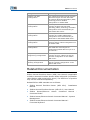


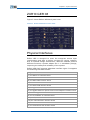
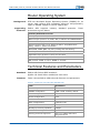
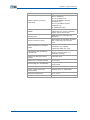


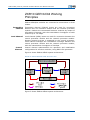


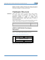
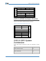
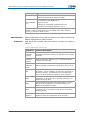

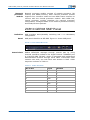
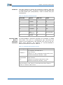
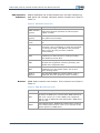

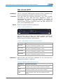

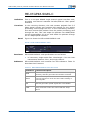
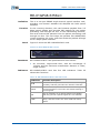
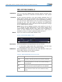
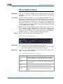


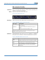


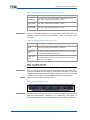
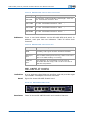

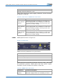
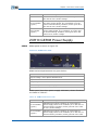
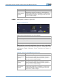


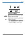
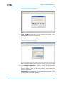

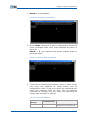
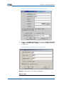


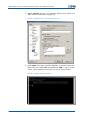
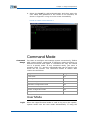


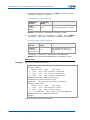
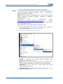
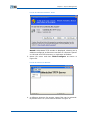

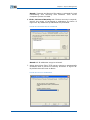
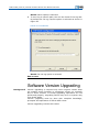
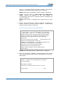


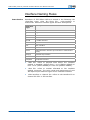


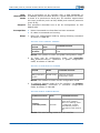
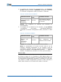
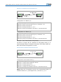


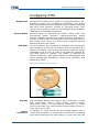
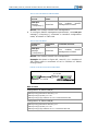
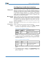
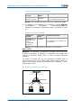
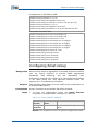

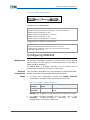
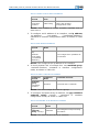

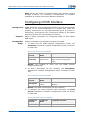

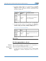

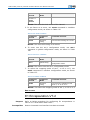

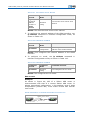
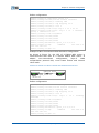

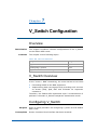
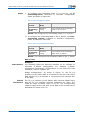
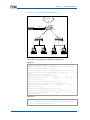
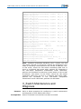


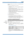


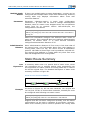

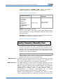


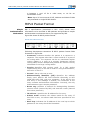
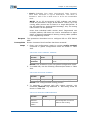

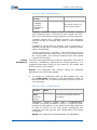
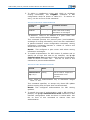
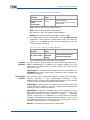
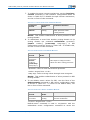


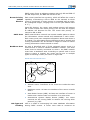

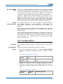
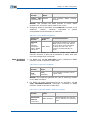

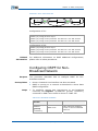

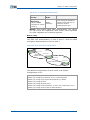


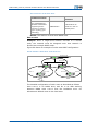
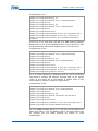
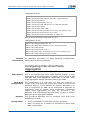
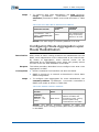


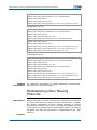
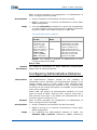
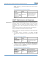
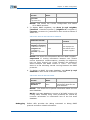
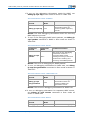


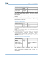
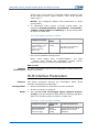
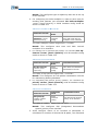
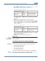

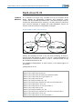
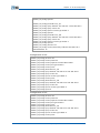
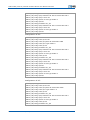


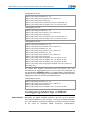

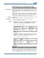
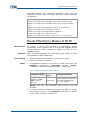
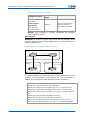


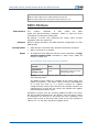
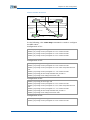

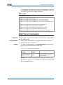
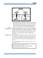
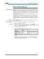
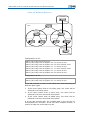
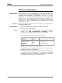
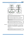


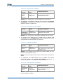
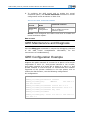
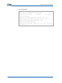

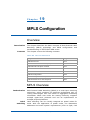


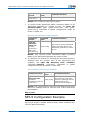


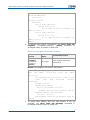
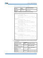
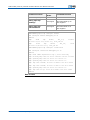


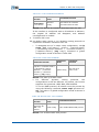

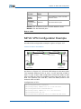
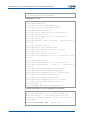


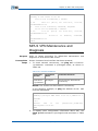
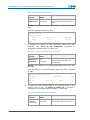

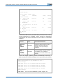


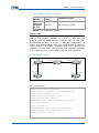

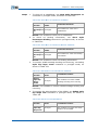

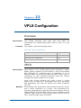
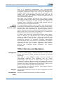
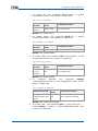
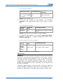
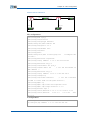
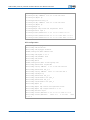
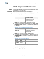


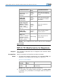
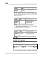


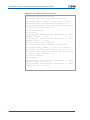


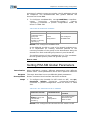
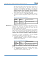
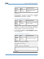


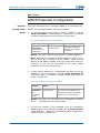
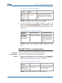
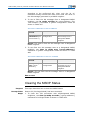
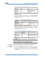
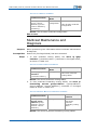
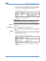

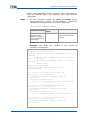
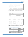


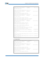
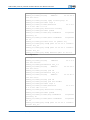


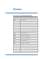


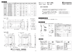
![KRF-V5200D - [::] Kenwood ASC](http://vs1.manualzilla.com/store/data/006743499_1-c2f44bf5511777a35ae85208e01f692e-150x150.png)