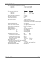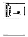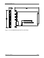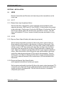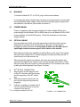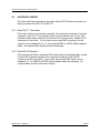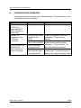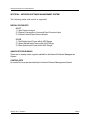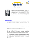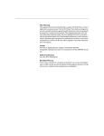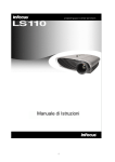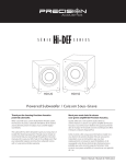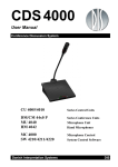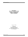
1
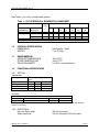
OPTELECOM MODEL 9311
USER’S MANUAL
FIBER OPTIC TRANSMISSION SYSTEM
HIGH RESOLUTION RGB/VGA VIDEO
MODEL 9311T TRANSMITTER
MODEL 9311R RECEIVER
February 27, 2002
OPTELECOM
12920 Cloverleaf Center Drive
Germantown, MD 20874
Phone: 800.29.FIBER (800.293.4237)
Fax: 301.444.2299
UM50230, Rev. C, ECO20917
01/14/04
1
OPTELECOM MODEL 9311
CONTENTS
Page
SECTION 1 - INTRODUCTION.....................................................................................................................................................3
1.1
GENERAL DESCRIPTION............................................................................................................................3
1.2
PHYSICAL SPECIFICATIONS....................................................................................................................5
1.3
ENVIRONMENTAL ................................................................................................................................................5
1.4
FUNCTIONAL SPECIFICATIONS ...........................................................................................................5
SECTION 2 - INSTALLATION ......................................................................................................................................................10
2.1
SETUP ...........................................................................................................................................................................10
2.2
MOUNTING ...............................................................................................................................................................11
2.3
POWER CABLING..............................................................................................................................................11
2.4
OPTICAL CABLING ...........................................................................................................................................11
2.5
ELECTRICAL CABLING................................................................................................................................12
SECTION 3 - OPERATION.............................................................................................................................................................13
3.1
TURN-ON PROCEDURE ...........................................................................................................................13
3.2
CONFIRMATION OF PROPER OPERATION ...........................................................................13
3.3
INDICATORS...........................................................................................................................................................13
3.4
ADJUSTMENTS....................................................................................................................................................13
3.5
TROUBLESHOOTING PROCEDURES........................................................................................14
SECTION 4 - NETWORK SOFTWARE MANAGEMENT SYSTEM.............................................................13
LIST OF FIGURES
Figure 1 - 9311T DIMENSIONS AND SWITCH LOCATIONS .............................................. 8
Figure 2 - 9311R DIMENSIONS AND SWITCH LOCATIONS .............................................. 8
Figure 3 - SETUP SWITCH ........................................................................................................ 9
®
Figure 4 - ST CONNECTION ................................................................................................. 11
LIST OF TABLES
Table 1 - LIST OF MODELS AND FEATURES ............................................................................................................ 4
Table 2 - SYNC DELAY RELATIVE TO VIDEO ............................................................................................................ 6
Table 3 - 9311T INDICATORS ................................................................................................................................................. 12
Table 4 - 9311R INDICATORS ................................................................................................................................................ 12
UM50230, Rev. C, ECO20917
01/14/04
2
OPTELECOM MODEL 9311
SECTION 1 - INTRODUCTION
1.1
GENERAL DESCRIPTION
The Model 9311T and 9311R Fiber Optic RGB High Resolution Video
Transmitter/Receiver pair allows the user to remote the video monitor from the
video generator via a much longer distance than allowable via copper coaxial
cables. They may also be used when electrical isolation or immunity from
noise in the transmission path is required.
There are three optical versions:
A)
The “H1” transmitter (using an 865 nm LED)/“S” receiver combination
provides a video bandwidth of up to 180 MHz via short fibers. The bandwidth
falls to about 105 MHz after approximately 600 meters of fiber and 50 MHz at
1200 meters. For this combination the primary effect on the bandwidth is
chromatic dispersion in the fiber, which is not greatly affected by fiber type.
B)
The “S” transmitter (using an 850 nm multimode LED) /“S” receiver
combination provides a video bandwidth up to 160 MHz via short fibers. The
bandwidth falls to 90 MHz after approximately 600 meters of fiber and to 40 MHz
at 1200 meters. The primary effect on the bandwidth is the chromatic
dispersion, which is not greatly affected by the fiber type.
C)
The “LD” transmitter (using a 1310 nm singlemode laser emitter)/“L”
receiver combination provides a video bandwidth of up to 220 MHz via short
fibers. The bandwidth is valid for the entire link budget.
The units require three optical fibers to operate. The sync signals are
combined and sent with the video on these fibers, eliminating the need for a
fourth or fifth fiber to carry the sync signals. They support each of the following
sync input/output combinations:
INPUT
OUTPUT
Sync-on-Green
Sync-on-Green
External Composite
Sync-on Green
External Horizontal and Vertical
Sync-on-Green
External Composite
External Composite
External Horizontal and Vertical
External Composite
External Horizontal and Vertical
External Horizontal and Vertical
NOTE: VGA, SVGA, XGA, and SXGA fall into the last category.
UM50230, Rev. C, ECO20917
01/14/04
3
OPTELECOM MODEL 9311
In the transmitter, all sync signals are first removed from the input(s). Then
calibrated sync signals are added to all colors for transmission via the fiber.
These sync signals are used as the Automatic Gain Control (AGC) references
by the receiver. These sync signals are then removed by the receiver unless
operating in Sync-on-Green mode. In this case the sync signal is not removed,
allowing it to be present on the Green video output. If external sync signals are
input to the transmitter it is possible to use a Sync-on-Green monitor by
enabling the Sync-on-Green output at the receiver via an on-board dipswitch.
In addition, if Sync-on-Green is input to the transmitter, a separate TTL
composite sync will be present at the output. If separate horizontal and vertical
syncs are input to the transmitter, separate TTL H&V sync output signals will be
available on the HS/CS and VS pins of the HD15 female connector on the
receiver. If separate composite sync signals are input it is possible to enable a
TTL composite sync from the HS/CS pins of the HD15 connector at the receiver
by setting the appropriate on-board dipswitch.
The transmitter will accept external sync inputs of either applied positive or
negative going sense and the receiver will return them in the same sense as
input. If Sync-on-Green only is utilized, the separate TTL level composite sync
output will be negative going. This feature of returning the external sync in the
same sense as applied allows the units to be transparent to any video/sync
formats (such as VGA) which utilize the sense of the sync signal to help the
monitor identify the scan rates utilized.
The transmitter automatically senses the presence external sync signals and
configures itself accordingly. If no external sync signals are applied it will
operate in Sync-on-Green mode and utilize the sync detected from the Green
channel. If a sync input is detected on the HS/CS input and it is recognized as
a composite sync (sync OK indicator Green) it will operate in external
composite sync mode. If a horizontal sync is detected at the HS/CS input a
vertical sync is not, the units will not operate properly (as indicated by a RED
Sync OK indicator on the transmitter). If both external H&V sync are applied to
the transmitter it will operate in that mode.
VGA/SVGA/XGA resolutions of up to 1840 x 1634 are supported depending on
fiber type and model selected. Horizontal scan rates of 15.75 kHz to 128 kHz
and vertical rates of 45 Hz to 150 Hz are supported.
The Models 9311T and 9311R are single-width card compatible with the 9000
series of card chassis. They operate on 6VDC power from the chassis
backplane. For rack-mount operation use the Model 9002 chassis. For
standalone operation use the Models 9003 or 9004.
The Models 9311T and 9311R are compatible with the standalone models
3654AR and 3654AT, respectively, and the older System 5000 compatible
Models 5654AR and 5654AT, in the multimode versions only.
UM50230, Rev. C, ECO20917
01/14/04
4
OPTELECOM MODEL 9311
See Table 1 for a list of models and options.
Table 1 - LIST OF MODELS vs. BANDWIDTH & LINK BUDGET
Model
TRANSMITTER
9311T-S-ST
9311T-H1-ST
λ
(nm)
RECEIVER
9311R-S-ST
9311R-S-ST
850
865
BW (MHz) vs. fiber length
2m
600m
160
180
9311R/HS-S-ST
865
150
9311T-LD-ST
9311R-L-ST
1310
220
* Depends on fiber distance x bandwidth product
1.2
1.3
1.4
Link budget
90
90
1.2
km
40
50
2.4
km
20
25
50/
125
N/A
4 dB
62/
125
5 dB
8 dB
09/
125
N/A
N/A
100
220
50
220
25
220
8 dB
N/A
11 dB
N/A
N/A
11 dB
PHYSICAL SPECIFICATIONS
DIMENSIONS
WEIGHT
See Figures 1 and 2
7 oz. (0.2 Kg.)
ENVIRONMENTAL
OPERATE TEMPERATURE
STORE TEMPERATURE
RELATIVE HUMIDITY
-20 to 50 C
o
-40 to 70 C
0 to 95%, noncondensing
o
FUNCTIONAL SPECIFICATIONS
1.4.1 OPTICAL
Transmitter
Fiber Type
50/125 µm fib er
62.5/125 µm fib er
09/125 µm fib er
Power output* (typical) in
dBm:
-S
-H1
-LD
N/A
-16
N/A
-14.5
-11.5
N/A
N/A
N/A
-11
Receiver
Receiver sensitivity* for 1V p-p output: minimum (typ.)
Version
-S
-HS
-L
-19.5
-22.5
-21
*Measured with a white field (white screen) video signal. These measurements vary with Average
Picture Level (APL).
1.4.2 ELECTRICAL
Sync-on-Green level
Video input level
UM50230, Rev. C, ECO20917
300 mV (nominal)
700 mV (nominal), 900 mV (max.)
01/14/04
5
OPTELECOM MODEL 9311
Ext. sync input levels (referenced to ground)
Low level
- 0.7 to + 0.3 V, typical
High level
+1.0 to +4.3 V, typical
Ext. sync output levels into;
Low level
High level
75 ohms
0V
+2V
300 ohms
0V typical
3.2 V typical
Video input/output impedance
Sync input impedance
Video/sync connectors
75 ohms
75 ohms
BNC
Sync source options
1) Sync-on-Green
2) External Composite Sync
3) Separate Ext. Horizontal and Vertical Sync
Video linearity distortion
Video output level mismatch
Video back porch clamp level
Output overshoot
Output settling time
SNR via 600’ link -H1-S-LD-
≤ 3% (typical)
≤ 2% (typical) for R, G, and B
0V ± 10 mV (typical)
≤ 15%
≤ 20 ns to less than 2%
≤ 45 dB (typical)
≤40 dB (typical)
≤54 dB (typical)
Video/Sync Timing Limits
Min
Max.
Horizontal sync pulse width
350 ns
5 µs
Horizontal back porch width
450 ns
Vertical sync. serration width
350 ns
Horizontal scan rate
15.75 kHz
128 kHz
Vertical frame rate
45 Hz
150 Hz
Differential delay among RGB video channels
≤ 300 ps
(assuming equal fiber delay)
Absolute video delay
18 to 20 ns (zero length fiber)
Sync Delay Relative to Video
See Table 2
UM50230, Rev. C, ECO20917
01/14/04
6
OPTELECOM MODEL 9311
Table 2 - SYNC DELAY RELATIVE TO VIDEO
Input Sync
Output Sync
Sync on Green
Sync on Green
Ext. comp. Sync
Ext. comp. sync
Ext. comp. Sync
Ext. horiz. sync
Ext. horiz. sync
Ext. vert. sync
Ext. vert. sync
Delay relative to video
+33 to +43 ns
+90 to +110 ns
+50 to +60 ns
+90 to +110 ns
H sync width +250 ns
1.4.3 POWER CONSUMPTION
9311T /MM
9311T/SM
6VDC @ 1.0 Amps
6VDC @ 1.25 Amps
9311R/MM
9311R/SM
6VDC @ 1.35 Amps
6VDC @ 1.5 Amps
1.4.4 COMPLIANCES
UM50230, Rev. C, ECO20917
CE
FCC Part 15, subpart J for class A equipment
01/14/04
7
OPTELECOM MODEL 9311
Figure 1 – 9311T DIMENSIONS AND SWITCH LOCATIONS (S and L Versions Shown)
UM50230, Rev. C, ECO20917
01/14/04
8
OPTELECOM MODEL 9311
Figure 2 – 9311R DIMENSIONS AND SWITCH LOCATIONS
UM50230, Rev. C, ECO20917
04/06/04
9
OPTELECOM MODEL 9311
SECTION 2 - INSTALLATION
2.1
SETUP
Both the Transmitter and Receiver units have two-position dipswitches on the
circuit card.
2.1.1
9311T
2.1.1.1External Sync Input Impedance Select
On the transmitter, a dipswitch is used to select the input impedance of the
external sync inputs, HS/CS and VS. See FIGURE 1 for the location of the switch
on the circuit card. Position one (1) is for the HS/CS input. Position two (2) is for
the VS input. Set the switch OFF for 300 ohms and ON for 75 ohms. Use 300
ohms as the default, 75 ohms if required usually for proper termination of long
cables.
2.1.2
9311R
2.1.2.1Sync-on-Green Output Enable (with external sync inputs)
On the receiver a dipswitch (position #1) allows the user to select a Sync-onGreen output from the receiver in the absence of a Sync-on-Green input. See
Figure 2 for the location of the switch on the circuit card. When switch position
number one (1) is OFF the receiver will output Sync-on-Green from the Green
output only if the transmitter has a Sync-on-Green input with no external sync
input. If there is an external sync input there will be no sync signal on the Green
output. When this switch is in the ON position sync will be added to the Green
output if an external composite sync (CS) is input to the transmitter. This will
allow for the use of Sync-on-Green monitors when only an external composite
sync (CS) or external horizontal (HS) or vertical syncs (VS) are available at the
transmitter.
2.1.2.2Composite External Sync Output Enable
(with separate horizontal and vertical sync inputs)
On the receiver a dipswitch (position #2) allows the user to select an external TTL
composite sync output even though separate external horizontal and vertical sync
signals are input to the transmitter. This will allow for the use of an external
composite sync monitor.
UM50230, Rev. C, ECO20917
04/06/04
10
OPTELECOM MODEL 9311
2.2
MOUNTING
To install the Model 9311T or 9311R, plug it into the card chassis
In mounting the chassis itself, make sure there is enough space to connect both
the electrical and optical cables to the panel without stressing them beyond the
manufacturer’s limitations (bend radius minimums).
2.3
POWER CABLING
Power is supplies via the chassis backplane for either a Model 9010 in-line
power supply (for the Models 9003 or 9004 chassis) or the Models 9030 or 9050
power supplies (for the 9002 chassis). Follow the instructions in the power
supply manual.
2.4
OPTICAL CABLING
Connect a fiber from the R port of the transmitter to the R port of the receiver.
Repeat the connections for the G and B ports. Because of optical pulse
propagation delay in the fibers, it is important to make sure the fibers are of
equal length to avoid misconvergence of the colors on the monitor.
Most cable manufacturers identify the individual fibers in the cable. Ensure that
the same fiber connects the ‘R’ optical output port of the transmitter and the ‘R’
optical input port of the receiver, etc.
When making the optical connections, first remove and save the plastic dust
caps from the optical ports on both units and from the fiber terminations. Clean
the ends of the fiber per supplier’s recommendation. ST connections are made
by taking the following steps (see Figure 3, below).
A.
1)
2)
3)
®
®
ST OPTICAL CONNECTION
Align the key and the bayonet slots
on the ST connector with the keyway
and the bayonets of the ST optical
port.
Slide the connector ferrule into the
port until the key and bayonets are
engaged.
Push the coupling nut forward until it
can be turned clockwise to lock the
connector into the port.
ST is a registered trademark of AT&T
FIGURE 3 – ST CONNECTION
UM50230, Rev. C, ECO20917
04/06/04
11
OPTELECOM MODEL 9311 USER'S MANUAL
2.5
ELECTRICAL CABLING
The Video and Sync connections are made via the HD15 Female connectors on
the front panels of the 9311T and 9311R.
2.5.1 Model 9311T Transmitter
If the video source is a personal computer, the video/sync connection from the
computer to the 9311T is most likely made using a standard pin for pin VGA
extension cable with a male HD15 connector on one end and a female HD15
connection on the other. If your video source uses BNC connectors for the
outputs, use a standard 3,4, or 5 (as required) BNC-to HD15P (Male) adapter
cable. All coaxial cables should be the same length.
2.5.2 Model 9311R Receiver
If the receiver will drive a standard VGA monitor with an attached cable, a maleto-male HB15 gender changer will be required to attach to the HD15S
connector on the front panel. If your video monitor has BNC inputs, use a
standard 3, 4, or 5 BNC-to-HD15P (male) adapter cable (as required). All
coaxial cables should be the same length.
UM50230, Rev. C, ECO20917
04/06/04
12
OPTELECOM MODEL 9311 USER'S MANUAL
SECTION 3 - OPERATION
3.1
TURN-ON PROCEDURE
To operate the units, connect the AC power cords and turn on the power switches
on the power supplies (if applicable). Confirm that the indicator lights come on.
3.2
CONFIRMATION OF PROPER OPERATION
If operating properly, the green “SYNC” indicator on the transmitter and all three
“LVL” indicators on the receivers will be illuminated Green. Good video
transmission will also be in evidence. On the transmitter, if external sync inputs
are present, either the HS/CS only or both the VS and HS/CS sync LEDs will be
illuminated.
3.3
INDICATORS
Table 3 – 9311T Indicators
Name
SYNC
Color
Green
NOT SYNC
CS/HS
Red
Green
VS
Green
Function
Illuminates when an acceptable sync input (with both
horizontal and vertical components) is detected.
Illuminates in the absence of an acceptable sync input
Illuminates when signal activity is detected at the CS/HS
sync input port.
Illuminates when signal activity is detected at the VS
sync input port.
Table 4 – 9311R Indicators
Name
B LVL
G LVL
R LVL
3.4
Color
Red/Green
Red/Green
Red/Green
Function
Off if there is an inadequate optical input signal power. Red if there
is excess optical input signal power. Green if the optical input signal
power is within the AGC operating range.
ADJUSTMENTS
There are no adjustments required under normal operation.
UM50230, Rev. C, ECO20917
04/06/04
13
OPTELECOM MODEL 9311 USER'S MANUAL
3.5
TROUBLESHOOTING PROCEDURES
If improper operation is evident, refer to the chart below. Consult the factory if you
are unable to correct the problem.
PROBLEM
SYNC indicator on the
9311T is not
illuminated (NOT
SYNC indicator is
illuminated)
No video LVL
indicators on the
9311R are
illuminated.
One or two video LVL
indicators not
illuminated but at
least one is green.
UM50230, Rev. C, ECO20917
POSSIBLE REASON
Improper connections
POSSIBLE SOLUTION
Confirm connections.
No sync on the optical
signals into the
9311T.
All optical links are
bad, or not connected.
One or more fibers
have excess loss.
One of the transmitter
video channels has a
bad optical emitter
Is the SYNC indicator on the 9311T
illuminated? Check the sync
source.
Check the output with an optical
power meter. Confirm the fiber
attenuation. Clean the fibers. Reterminate the fibers if needed.
Check the output with an optical
power meter. To meet the specs, a
white screen signal should be used.
04/06/04
14
OPTELECOM MODEL 9311 USER'S MANUAL
SECTION 4 – NETWORK SOFTWARE MANAGEMENT SYSTEM
The following status and control is supported:
DIGITAL STATUS BITS
9311T
1) Sync Present at Input
2) External Composite or Horizontal Sync Present at Input
3) External Vertical Sync Present at Input
9311R
1) Red Optical Input Power within AGC Range
2) Green Optical Input Power within AGC Range
3) Blue Optical Input Power within AGC Range
ANALOG STATUS SIGNALS
There are no analog status signals available to the Network Software Management
System.
CONTROL BITS
No control bits may be exercised by the Network Software Management System.
UM50230, Rev. C, ECO20917
04/06/04
15