1
¡
MICROLINE 3320/3321
PRINTER
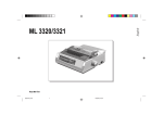
Product Specifications
Approval
All specifications are subject to change without notice.
CONTENTS
1.
INTRODUCTION ................................................................................................................... 1-1
2.
CONFIGURATION ................................................................................................................. 2-1
3.
4.
5.
6.
7.
2.1
Standard Printer Configuration .................................................................................. 2-1
2.2
Options ....................................................................................................................... 2-1
2.3
Block Diagram ............................................................................................................ 2-1
2.4
Initial Setting ............................................................................................................... 2-2
GENERAL SPECIFICATIONS .............................................................................................. 3-1
3.1
Power Requirements .................................................................................................. 3-1
3.2
Electric Insulation ....................................................................................................... 3-1
3.3
Environmental Conditions .......................................................................................... 3-1
3.4
Agency Approvals ...................................................................................................... 3-2
3.5
Communication Interface Specifications ................................................................... 3-2
PHYSICAL CHARACTERISTICs ......................................................................................... 4-1
4.1
Printhead .................................................................................................................... 4-1
4.2
Printer ......................................................................................................................... 4-1
4.3
Options ....................................................................................................................... 4-3
LOGICAL CHARACTERISTICS ........................................................................................... 5-1
5.1
Print Direction ............................................................................................................. 5-1
5.2
Selectable Characters Pitches .................................................................................. 5-1
5.3
Maximum Number of Dot Columns per Line ........................................................... 5-1
5.4
Maximum Number of Characters per Line ............................................................... 5-1
5.5
Line Feed Pitches ...................................................................................................... 5-2
PRINTER PERFORMANCE ................................................................................................. 6-1
6.1
Print Speed ................................................................................................................ 6-1
6.2
Throughput (Lines per Minute) .................................................................................. 6-1
6.3
Line Feed Speed ....................................................................................................... 6-2
MEDIA SPECIFICATIONS .................................................................................................... 7-1
7.1
Cut-Sheet Paper ........................................................................................................ 7-1
7.2
Continuous Paper ...................................................................................................... 7-1
7.3
Cut Form Envelope .................................................................................................... 7-1
7.4
Continuous Envelope ................................................................................................. 7-1
7.5
Card ............................................................................................................................ 7-2
7.6
Label ........................................................................................................................... 7-2
7.7
Transparency .............................................................................................................. 7-2
i
8.
PAPER FEED SPECIFICATIONS ....................................................................................... 8-1
8.1
Paper Feed Methods/Paths ....................................................................................... 8-1
8.2
Paper Positioning Restrictions ................................................................................... 8-1
8.3
Paper Tear-off ............................................................................................................ 8-1
8.4
Automatic Sheet Loading .......................................................................................... 8-1
8.5
Paper End Detection ................................................................................................. 8-1
9.
RIBBON SPECIFICATIONS ................................................................................................. 9-1
10.
RELIABILITY ....................................................................................................................... 10-1
11.
OPERATOR CONTROL ..................................................................................................... 11-1
11.1
Operator Control Switches and Indicator Lights ..................................................... 11-1
11.2
Switch Functions ...................................................................................................... 11-1
11.3
Indicator Light Functions ......................................................................................... 11-4
11.3.1 Primary Functions ....................................................................................... 11-4
11.3.2 Secondary Functions .................................................................................. 11-4
11.4
Alarm/Error lndications ............................................................................................. 11-5
11.4.1 Recoverable Alarms .................................................................................... 11-5
11.5
Secondary Switch Functions ................................................................................... 11-7
11.5.1 MENU .......................................................................................................... 11-7
11.5.2 Sample Print Self-test ............................................................................... 11-14
11.5.3 Rolling ASCII Self-test .............................................................................. 11-15
11.5.4 Hex-dump .................................................................................................. 11-16
11.5.5 Auto Park/lnsert Sheet ............................................................................. 11-17
11.5.6 Form Tear-off ............................................................................................ 11-18
12. COMMAND DESCRIPTION
12.1
Horizontal Control .................................................................................................... 12-1
12.2
Vertical Control ....................................................................................................... 12-17
12.3
Symbol Sets ........................................................................................................... 12-43
12.4
Font Description ..................................................................................................... 12-52
12.5
Text Print Features ................................................................................................ 12-84
12.6
Graphics Mode ..................................................................................................... 12-100
12.7
Composite Commands......................................................................................... 12-115
12.8
General Control .................................................................................................... 12-121
12.9
Bar Code .............................................................................................................. 12-130
ii
APPENDIX A BIT IMAGE GRAPHICS—DOT DENSITY ............................................................... A-1
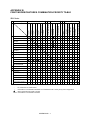
APPENDIX B PRINT MODES/FEATURES COMBINATION PRIORITY TABLE........................... B-1
APPENDIX C COMMAND SUMMARY ........................................................................................... C-1
iii
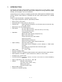
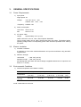
1.
INTRODUCTION
The Microline 3320/3321 (ML/Epson/lBM compatible) model printer is a highly reliable, rugged,
high performance desk-top serial dot matrix printer, designed for strong, feature-rich paper
handling, fast throughput, and user friendliness.
The ML3320 (narrow chassis) is compatible with ML Printer, IBM Proprinter lll, EPSON FX-850,
while the ML3321 (wide chassis) is compatible with ML Printer, IBM Proprinter lll XL, EPSON
FX-1050.
Feature of the ML3320/3321 compatible printer include:
— 9-pin single arrangement operator replaceable printhead
— Direct access control panel
— Structured direct access menu for easy set up
— Printhead life:
200M characters (average) in 10 CPl Draft mode at normal 25% duty,
35% page density
— Bidirectional short-line-seeking printing
— Print speed:
387 CPS HSD (all CPl’s)
290 CPS Utility (all CPl’s) SSD 435 CPS (12 CPI Only)
72.5 CPS NLQ (all CPl’s)
— Paperfeed :
Top/Rear/Bottom path
Bottom path (with optional push/pull tractor)
Built-in rear push tractor
Friction feed with pinch roller release
Optional pull tractor
Optional bottom push tractor
Optional Cut-Sheet Feeder (single bin/dual bin)
— Paper handling :
Automatic sheet loading
Short paper tear-off available by menu selection or TEAR switch
operation
Auto-loading for single sheet and continuous paper
Auto park feature
— Paper copies:
12 – 24 Ib, 5 part
— Re-inking cartridge ribbon
— Standard Centronics compatible parallel interface and optional RS-232C serial interface
— Quiet operation at 52 dBA in a quiet mode and 57 dBA at a normal mode
— 28 kbytes max. receive buffer
— Line feed resolution at 1/6 inch, 1/8 inch, n/72 inch, n/144 n/144 inch, n/216 simulated by
n/288 inch
— Agency approved by CSA, FCC and UL, VDE, BS
— Options:
RS-232C Serial Interface
Pull tractor (with acoustic cover)
Bottom push tractor
Cut-Sheet Feeder (CSf)
— Barcode data printing
— Postnet bar code data printing
1–1
2.
CONFIGURATION
2.1 Standard Printer Configuration
The ML3320/3321 ML/EPSON/IBM
2.2
1)
Printer mechanism
2)
Power & Control board
3)
Driver board (including Centronics-compatible Parallel Interface)
4)
Operator control panel
5)
Power supply
6)
Acoustic covers
7)
Push tractor feed unit
Options
1)
Interface boards
RS-232C Serial Interface board (communications rate up to 19.2 K BPS)
2.3
2)
Push/pull tractor feed with acoustic cover
3)
Bottom Push tractor feed
4)
Cut-Sheet Feeder
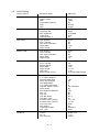
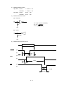
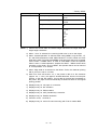
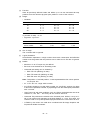
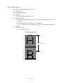
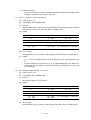
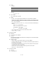
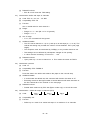
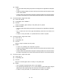
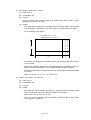
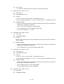
Block Diagram
(Option)
CSF
Interface
cable
AC source
Power supply
Power & control board
Transformer
Filter board
(Option)
Interface
board
Printhead
M
Space
motor
LF motor
Driver
board
Operation control
panel
Figure 2-1 Block Diagram
2–1
M
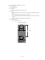
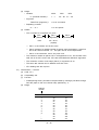
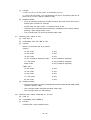
2.4
Initial Setting
Printer Control
Emulation Mode
IBM PPR
Font
Print mode
DRAFT mode
Pitch
Proportional Spacing
Style
Size
Utility
HSD
10CPI
No
Normal
Single
Symbol Sets
Character Set
Language Set
Zero Character
Code Page
Slashed Letter 0
Set 2
ASCII
Unslashed
USA
No
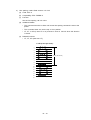
Rear Feed
Line Spacing
Form Tear-Off
Skip Over Perforation
Page Width
Page Length
6 LPI
Off
No
13.6"
12"
Bottom Feed
Line Spacing
Form Tear-Off
Skip Over Perforation
Page Width
Page Length
6 LPI
Off
No
13.6"
12"
Top Feed
Line Spacing
Form Tear-Off
Bottom Margin
Page Width
Page Length
Wait Time
Page Length Control
6 LPI
Off
Valid
13.6"
11 2/3"
1 sec
by Actual Page Length
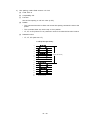
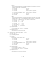
Set-Up
Graphics
7 or 8 Bits Graphics
Receive Buffer Size
Paper Out Override
Print Registration
7 or 8 Bits Data Word
Operator Panel Function
Reset Inhibit
Print Suppress Effective
Auto LF
Auto CR
CSF Bin Select
Print DEL Code
Sl Select Pitch (10CPI)
Sl Select Pitch (12CPI)
Time Out Print
Auto Select
Centering Position
CSF Type
Bi-directional
7
16K
No
0
8
Full Operation
No
Yes
No
No
Bin 1
No
17.1 CPI
12 CPI
Valid
No
DEFAULT
Wide
Parallel I/F
I-Prime
Pin 18
Auto Feed XT
Buffer Print
+ 5V
Invalid
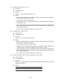
2–2
Serial I/F
Parity
Serial Data 7/8 Bits
Protocol
Diagnostic Text
Busy Line
Baud Rate
DSR Signal
DTR Signal
Busy Time
None
8 Bits
Ready/Busy
No
SSD9600 BPS
Valid
Ready on Power Up
200 ms
CSF Bin 1
Line Spacing
Bottom Margin
Page Width
Page Length
6 LPI
Valid
13.6"
11 2/3"
CSF Bin 2
Line Spacing
Bottom Margin
Page Length
6 LPI
Valid
11 2/3"
2–3
3.
GENERAL SPECIFICATIONS
3.1
Power Requirements
1)
Input power
Single-phase AC
Voltage:
120 VAC +5.5%, –15%
230/240 VAC +10%, –14%
Frequency: 50/60Hz +2%
2)
3)
Power consumption
Local Test:
About 70 VA
Idle:
About 41 VA
AC power cable
Length:
Approximately 5.9 ft (1.8 m)
Cable conforms to the UL, CSA, and European Standards.
The AC power cable can be easily disconnected from the printer. The desired printer
operating voltage and the corresponding power cable should be specified when ordering
the printer.
3.2
Electric Insulation
1)
Insulation resistance
5 megohms or more when measured between AC input line and frame using 500-VDC
megohmmeter.
2)
Dielectric strength
120Vmodel:
1,250 VAC (50 Hz)
230/240V model:
1,500 VAC (50 Hz)
(No damage will result when the above voltage is applied between the AC input line and
frame for 1 minute.)
3.3
Environmental Conditions
1)
Ambient temperature and relative humidity
Operating
Non-operating Transportation
Storage
Unit
Temperature
41 to 104
(5 to 40)
32 to 109.4
(–0 to 43)
–40 to 158
(–40 to 70)
14 to 122
(–10 to 50)
°F
(°C)
Relative
Humidity
20 to 80
10 to 90
5 to 95
5 to 95
% RH
Avoid condensation at all times.
3–1
2)
Vibration
Operating:
0.3G (5 to 150 Hz) or less (except at resonant frequency)
Non-operating: 1G (5 to 150 Hz) or less (except at resonant frequency)
Packing:
3)
Impact (Drop Test)
Packing:
4)
1.05G (5 to 150 Hz) or less (except at resonant frequency)
30" Drop
Noise
The 8-second average noise is less than 57 dBA when measured under the above
conditions with the printer fitted with the acoustic cover and 52 dBA in quiet mode. (ISO
7779)
3.4
Agency Approvals
UL No.: The printer is listed in UL STANDARD No. 1950.
CSA No.:
CSA certification to CSA STANDARD 22.2-950.
FCC:
FCC certified per Part 15, CLASS B.
VDE:
VDE 0805 VDE 0875 class B.
IEC:
IEC 950
BS:
BS 7002
EN 55022 Class B (CE mark)
3.5
Communication Interface Specifications
A.
Centronics-compatible Parallel Interface
1)
Connectors and cable
(a)
(b)
Connectors
Printer side:
36-pin receptacle 57RE-40360-730B-D29A6 (Daiichi Electronics) or
equivalent
Cable side:
36-pin plug 57-30360 (Amphenol or Daiichi Electronics) or equivalent,
or plug 552274-1 (Amphenol) cover 552073-1 (Amphenol) or equivalent
Cable
Use cable less than 6 ft (1.8 m) in overall length. (A shielded cable is required, and
use of twisted-pair wires is recommended for noise prevention.)
Note: Interface cable is not supplied.
3–2
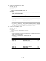
2)
Parallel interface signals
Pin No.
Signal
Direction
1
DATA STOROBE
To printer
2
DATA BIT 1
To printer
3
4
5
6
7
8
9
10
DATA BIT2
DATA BIT3
DATA BIT4
DATA BIT5
DATA BIT6
DATA BIT7
DATA BIT8
ACKNOWLEDGE
From printer
11
BUSY
From printer
12
13
14
PAPER END
SELECT
AUTO FEED
From printer
From printer
To printer
16, 33
17
18
0V
CHASSIS
GROUND
+ 5V
19 to 30 0V
31
INPUT-PRIME
32
FAULT
15, 34
35
—
—
36
(Select-In)
—
—
From printer
—
To printer
From printer
—
—
To printer
Description
Sample input data when changing from low
level to high level.
Input data: High level indicates “ 1 “ and low
level
Indicates character input completion, or function
operation end, at low level.
Indicates data cannot be received at high level.
Data can be input at low level.
High level indicates paper end.
High level indicates select (online) condition.
When "Auto Feed" in the menu is set as valid
under EPSON mode, this signal goes to the low
level and the printer generates a line feed after
receiving CR code.
Signal ground.
Frame ground.
+5V supply (50 mA maximum)
+5V on/off is selectable by MENU.
Twisted pair return (for pin No. 1 to 11)
When this signal goes to the low level, printer
controller is initialized. The low level should be
held for more than 0.5 ms.
This signal goes from high to low level when
paper runs out.
(Possible to indicate error and OFF-Line state).
Unused
Fixed to High
(Connected to +5V thru 3.3K)
In the EPSON mode, when menu item "Print
Suppress Effective" is Yes, and the Select-In
signal is high, the DC1/DC3 code is valid, and
invalid when the signal is low.
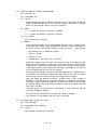
Note: Pin arrangement
18
1
36
19
3–3
3)
Parallel interface levels
High level: Driver:
Low level:
4)
+ 2.4V to + 5V
Receiver:
+ 2.0V to + 5V
Driver:
0V to + .4V
Receiver:
0V to + .8V
Parallel Interface circuits
(a)
Receiver
R = 3.3 KΩ (Data 1 to Data 8)
R = 1 KΩ (I-PRIME)
R = KΩ (STB) (USA)
R
+5V
(b)
Driver
3.3 KΩ
+5V
5)
Parallel Interface timing chart
DATA
STROBE
(H)
(L)
1µS
min
BUSY
1µS
1~500µS min
(H)
(L)
T busy
ACK
(H)
500 ns
max
(L)
t1
t1
2~8µS
3–4
t1 = 1~4µS
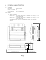
4.
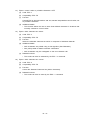
PHYSICAL CHARACTERISTICS
4. 1 Printhead
Impact dot matrix
Number of dot wires:
9
Dot wire diameter:
0.013 inch (0.34 mm)
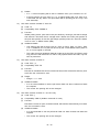
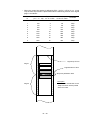
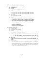
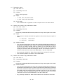
Printer
Outside dimensions
ML320 Turbo:
15.67 inches (398 mm) (W) × 4.57 inches (116 mm) (H) × 13.58
inches (345 mm) (D)
ML321 Turbo:
21.73 inches (552 mm) (W) × 4.57 inches (116 mm) (H) × 13.58
inches (345 mm) (D)
15.67 inches (398 mm)
1.50 inches (38 mm)
ML3320
4–1
15.91 inches (404 mm)
13.58 inches (345 mm)
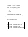
These dimensions do not include the platen knob, acoustic cover and paper
separator.
5.79 inches (147 mm)
1)
4.57 inches (116 mm)
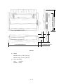
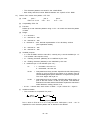
4.2
Print method:
Weight
ML3320 Turbo: 14.33 Ib (6.5 kg)
ML3321 Turbo: 18.74 Ib (8.5 kg)
3)
Color and texture
Color:
3.5Y8/0.5
Texture:
TH114
4–2
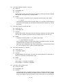
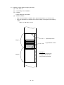
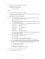
15.91 inches (404 mm)
13.58 inches (345 mm)
ML3321
2)
5.79 inches (147 mm)
4.57 inches (116 mm)
1.50 inches (38 mm)
21.73 inches (552 mm)
4.3
Options
(1)
Interface board
RS-232C serial interface board (communications rate up to 19.2 KBPS)
(2)
Tractor feed unit with acoustic cover for Pull Feed or Bi-directional
(3)
Bottom push tractor feed unit for Bottom push feed
(4)
Cut-Sheet Feeder (Single bin/Dual bin)
4–3
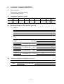
5.
LOGICAL CHARACTERISTICS
5.1
Print Direction
Bidirectional, unidirectional printing
Short-line-seeking printing
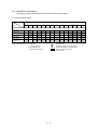
5.2
Selectable Character Pitches
5 CPI
6 CPI
0.2 inch
0.167 inch
(5.08 mm) (4.23 mm)
7.5 CPI
8.5 CPI
10 CPI
0.133 inch 0.117 inch
0.1 inch
12 CPI
15 CPI
17.1 CPI
0.083 inch 0.067 inch 0.058 inch
(3.39 mm) (2.96 mm) (2.54 mm) (2.12 mm) (1.69 mm)
20 CPI
0.05 inch
(1.48 mm) (1.27 mm)
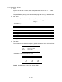
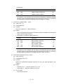
5.3 Maximum Number of Dot Columns per Line
1)
2)
Graphics
Single Density
Double Density
Quadruple Density
ML3320
480
960
1,920
ML3321
816
1,632
3,264
Text
Model
Character Pitch (CPI)
Print Mode
10 CPI 12 CPI 15 CPI 17.1 CPI 20 CPI
ML3320
ML3321
ML,
ML,EPSON,
EPSON,IBM
IBM
UTILITY
UTILITY
ML,
ML,EPSON
EPSON,IBM
IBM
NLQ
ML,
ML,EPSON
EPSON,IBM
IBM
HSD
ML,
ML,EPSON
EPSON,IBM
IBM
SSD
ML3320
ML3321
ML3320
ML3321
960
1,152
1,440
1,646
1,920
1,632
1,958
2,448
2,798
3,264
1,920
2,304
2,880
3,292
3,840
3,264
3,917
4,896
5,596
6,528
720
864
1,080
1,234
1,440
1,224
1,468
1,836
2,098
2,448
ML3320
768
ML3321
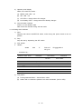
5.4
1,305
Maximun Number of Character per Line
Character Pitch (CPI)
Mode
ML3320
5
ML EPSON IBM
ML3321
5–1
6 7.5
60
8.5
10
12
15 17.1
20
68
80
40
48
96
120 137
160
68
81 102 116 136 163
204 233
272
5.5
Line Feed Pitches
6 LPI 0.167 inch (4.23 mm)
8 LPI 0.125 inch (3.175 mm)
A variable line feed pitch of n/216 inch (integer n: 0 ≤ n ≤ 255) can also be specified. Also,
7/72 inch and n/72 inch can be specified.
PROPRINTER n: 1 ≤ n ≤ 255
EPSON
n: 1 ≤ n ≤ 255 (Cannot specify MSB: 1 ≤ n ≤ 127)
5–2
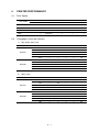
6.
PRINTER PERFORMANCE
6.1
Print Speed
Print Mode
Character Pitch
10 CPI
12 CPI
15 CPI
17. 1 CPI
20 CPI
HSD
387 CPS
387 CPS
387 CPS
387 CPS
387 CPS
NLQ
72.5 CPS
72.5 CPS
72.5 CPS
72.5 CPS
72.5 CPS
UTILITY
290 CPS
290 CPS
290 CPS
290 CPS
290 CPS
—
435 CPS
—
—
—
SSD
6.2
Throughput (Lines per Minute)
1)
High speed draft mode
Model
ML3321
ML3320
2)
Characters/Line 10 CPI
136
163
204
233
272
80
96
120
137
160
127
—
—
—
—
191
—
—
—
—
12 CPI
15 CPI
—
112
—
—
—
—
171
—
—
—
—
—
93
—
—
—
—
146
—
—
12 CPI
15 CPI
—
90
—
—
—
—
141
—
—
—
—
—
74
—
—
—
—
118
—
—
17.1 CPI 20 CPI
—
—
—
84
—
—
—
—
132
—
—
—
—
—
73
—
—
—
—
117
Utility mode
Model
ML3321
ML3320
Characters/Line 10 CPI
136
163
204
233
272
80
96
120
137
160
104
—
—
—
—
161
—
—
—
—
6–1
17.1 CPI 20 CPI
—
—
—
65
—
—
—
—
106
—
—
—
—
—
57
—
—
—
—
92
3)
Near letter quality mode
Model
Characters/Line
ML3321
ML3320
4)
Characater Pitch
10 CPI
12 CPI
15 CPI
17.1 CPI
20 CPI
136
29
—
—
—
—
163
—
24
—
—
—
204
—
—
19
—
—
233
—
—
—
17
—
272
—
—
—
—
15
80
48
—
—
—
—
96
—
40
—
—
—
120
—
—
32
—
—
137
—
—
—
28
—
160
—
—
—
—
25
Super speed draft mode
Model
Characters/Line
ML3321
ML3320
Characater Pitch
10 CPI
12 CPI
15 CPI
17.1 CPI
20 CPI
136
—
122
—
—
—
96
—
184
—
—
—
The above table specifies the print speeds at a line feed pitch of 6 LPI in the normal print mode.
6.3
Line Feed Speed
6 LPI spacing, one LF = 65 ms
8 LPI spacing, one LF = 60 ms
Continuous paper feed rate is at 4.5 inches per second.
6–2
7.
MEDIA SPECIFICATIONS
7.1
Cut-Sheet Paper
7.2
Standard size:
8-1/2 inches (wide) × 11 inches (long) for the U.S. A4 size (210mm (wide)
× 297 mm (long)) for Europe
Weight:
12 to 24 Ib (45 to 90 g/m2)
Multiple-part cut-sheet paper cannot be used.
Continuous Paper
Tractor feed unit can handle sprocket paper of the following widths:
ML3320 : 3 to 10 inches (76.2 to 254 mm)
ML3321 : 3 to 16 inches (76.2 to 406.4 mm)
One-part paper
Ream weight:
12 to 24 Ib (45 to 90 g/m2)
Multiple-part paper:
0.014 inch (0.356 mm) or less total thickness
0. 017 inch (0.44 mm) or less total thickness (bottom path only)
Ream Weight
Carbon-lined paper
9 to 11 lb
Pressure-sensitive paper
Interleaf paper
Up to 5
g/m 2)
including original
10 lb to 12 lb
(38 to 45 g/m 2)
Up to 5
including original
(35 to 40
PAPER
Number of Sheets
9 lb
(34 g/m2)
CARBON
Multiple-part paper should be fastened by spot-pasting or crimping on both sides, and should
be free of wrinkles.
7.3
Cut Form Envelope
Weight:
24 Ib (90 g/m 2) or l ess
Thickness:
0.0 16 inch (0.41 mm or less)
6-1/2 × 3-5/8 inches
8-7/8 × 3-7/8 inches
9-1/2 × 4-1/8 inches
7.4
Continuous Envelope
Weight:
24 Ib (90 g/m2) or less
Thickness:
0.014 inch (0.36 mm or less)
Width:
3 – 10 inches (76.2 – 254 mm)
Media supply:
Bottom paper feed only
7–1
7.5
7.6
Card
Weight:
120 Ib (163 g/m2) or less
Thickness:
0.008 inch (0.20 mm) or less
Size:
5 × 8 inches (separated)
Media supply:
Bottom paper feed only
Label
Thickness:
0.011 inch (0.28 mm) or less
Size:
ML3320 -8.5 × 3.25 inches(216 × 83 mm) or less
ML3321 -15 × 3.25 inches (381 × 83 mm) or less
Media supply:
7.7
Bottom paper feed only
Transparency
Thickness:
0.004 inch (0.10 mm) or less
Size:
8.5 × 11 inches (216 × 280 mm) or less
7–2
8.
PAPER FEED SPECIFICATIONS
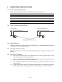
8.1
Paper Feed Methods/Paths
When the friction feed method is used, the paper must be fed from rear.
ML3320
8.2
ML3321
(a) Friction feed (Top path)
For cut-sheet paper only
For cut-sheet paper only
(b) Push tractor feed (Rear path)
For continuous forms
For continuous forms
(c) Push-pull-traction paper feed (option)
For continuous forms
For continuous forms
(d) Pull tractor feed (Bottom path) (option)
For continuous forms
For continuous forms
(e) Bottom push tractor feed (option)
For continuous forms
For continuous forms
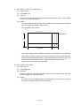
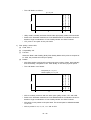
Paper Positioning Restrictions
(Friction feed)
(Push-pull tractor feed )
0.35 inch (8.9 mm) or more
0.35 inch (8.9 mm) or more
Printing position on the first dot
8.3
Paper Tear-off
The paper can be torn off 0.42 inch above the first printed line. A sharp serrated edge is provided
on the access cover for paper tear-off.
8.4
Automatic Sheet Loading
With top paper feed, cut-sheets can be automatically loaded by setting paper at the top feed
position.
8.5
Paper End Detection
(1)
With rear paper feed, the paper end is detected when the remaining paper length is about
1 inch (25.4 mm) from the last printed line.
(2)
With bottom paper feed, the paper end is detected when the remaining paper length is
about 1 inch (25.4 mm) from the last printed line.
(3)
Upon detecting the paper end, the printer stops printing and sends a paper end signal
to the interface.
(4)
A paper end override function is available to allow printing to be performed line-by-line
under operator control after the paper end has been detected. (rear, and bottom)
8–1
9.
RIBBON SPECIFICATIONS
Genuine OKI cartridge ribbon
Ink color:
Black
Ribbon life:
Approximately 3 million characters (Re-inking cartridge)
9–1
10. RELIABILITY
1)
MTBF (mean time between failures)
10,000 hours of power-on time
Page density: 35%
Duty cycle:
2)
25%
Printhead life
200 million characters (average) in 10 CPI Draft print quality
Page density: 35%
Duty cycle:
3)
25%
Printer life
12,000 hours of power-on time
Page density: 35%
Duty cycle:
4)
25%
MTTR
15 minutes Major Sub-assembly level
10 – 1
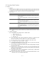
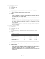
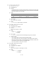
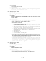
11. OPERATOR CONTROL
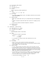
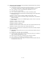
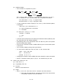
11.1 Operator Control Switches and Indicator Lights
Locations of Switches and Indicator Lights
ML3320/3321 OPERATOR PANEL
PRINT QUALITY
SEL
SEL
MENU
EXIT
POWER
SHIFT
LF
FF/LOAD
Micro Feed
Down
Micro Feed
Up
GROUP
ITEM
ALARM
TEAR
SET
MENU
PARK
QUIET
TOF
HSD
UTILITY
NLQ
SSD
CHARACTER PITCH
PRINT
RESET
10
12
15
17
20
PROP
11.2 Switch Functions
The functions of the switches on the operator panel depend on the state of the printer. Each
function is described in the following table.
The Functions of Switches (1/2) (Without pressing the SHlFT switch) (1/2)
MODE
MODE
SW
SW
SEL/
MENU
Print Mode
Select
Sets
printer
off line.
Deselect
Sets
printer
on line.
Hex Dump Mode
Select
Sets
printer
off line.
Deselect
Sets
printer
on line.
Menu
Mode
Clears
MENU
PAPER
END.
Test
Mode
Ends
TEST
mode.
Power On
Mode
Starts MENU
mode.
SHIFT
LF/Micro
Feed
Down
FF/LOAD/
Micro
Feed Up
Limited
Operation
Mode
Enabled.
Enabled.
Performs line feed. *1, 2
Selects
next
Group.
• When paper is set:
— If cut-sheet paper is used, the paper
is ejected.
— If fan fold paper is used, the printer
feeds paper up to the next TOF
position.
• When no paper is set while printer
status is "deselect," the printer loads
paper.
Selects
next
Item. *3
11 – 1
Starts Self-test.
Enabled.
Enabled.
The Functions of Switches (1/2) (While pressing the SHlFTswitch) (2/2)
MODE
Print Mode
Select Deselect
SW
Hex Dump Mode
Select
Menu
Mode
Test
Mode
Power On
Mode
Deselect
Limited
Operation
Mode
TEAR
Feeds paper to tear or print position
(alternating)
Selects
next
Setting.
Enabled.
PARK
Cut-sheet paper: Printer ejects paper.
Fan fold paper: Printer reverse feeds
paper.
Prints all
items.
Enabled.
QUIET/
TOF
Starts Rolling
ASCII Self-test.
Selects/ends QUIET mode.
CHARACTER
PITCH
Selects character
pitch.
PRINT
QUALITY
Selects PRINT
mode.
FF/LOAD+
TEAR
Resets to the
default menu
and paper load
position.
SEL+LF
Resets to the
default features
in MENU mode.
QUIET+
PARK
Resets to the
default paper
load position.
SEL+
FF/LOAD
Starts
Hex-dump
mode.
SEL+
QUIET
Sets fixed menu or header values (stored in ROM).
Resets to the default suction position.
SEL+
TEAR
Starts Menu Maintenance Mode.
SEL+
PARK
Clears frequency-of-printer-use data.
*1:
When no CSF mode paper is set, the printer loads paper.
*2:
When the LF/Micro Feed Down switch is pressed for 400ms or more, the printer performs a
continuous LF operation.
*3:
When no paper is set, the printer loads paper.
Note: The blanks in the above table denote no operation.
11 – 2
The Functions of Switches (2/2) (Without pressing the SHlFTswitch)
MODE
Print Mode
Hex Dump Mode
Select Deselect
SW
SEL/
MENU
Select
Deselect
Menu
Mode
Ends
MENU
mode.
SETS MENU MODE.
Test
Mode
Power On
Mode
Limited
Operation
Mode
Starts MENU
mode.
SHIFT
Enabled.
LF/Micro
Feed
Down
Executes
Reverse
Fine LF.
Executes
Reverse
Fine LF.
Select
previous
Item.
FF/LOAD/
Micro
Feed Up
Executes
Forward
Fine LF.
Executes
Forward
Fine LF.
Select
previous
Group.
Enabled.
Enabled.
TEAR
Execute
Backward
vertical
paper
feed
Select
previous
Setting.
PARK
Execute
vertical
paper
feed.
Prints
Group
items.
QUIET/TOF
Sets
TOF. *4
Sets
TOF. *4
CHARACTER
PITCH
Resets
printer.
Resets
printer.
PRINT
QUALITY
Starts Self-test.
Starts Rolling
ASCII Self-test.
Prints all
items.
(All)
Select/deselect
incrimental print
mode.
FF/LOAD+
TEAR
Resets to the
default menu
and paper load
position.
SEL+LF
Resets to the
default features
in MENU mode.
QUIET+
PARK
Resets to the
default paper
load position.
SEL+
FF/LOAD
Starts
Hex-dump
mode.
SEL+
QUIET
Sets fixed menu or header values (stored in ROM).
Resets to the default suction position.
SEL+TEAR
Starts Menu Maintenance Mode.
SEL+PARK
Clears frequency-of-printer-use data.
*4:
Enabled.
When no paper is set, the printer load position is set to factory default.
Note: The blanks in the above table denote no operation.
11 – 3
11.3 Indicator Light Functions
11.3.1 Primary Functions
Lamp
Color
Function
SEL
Amber
Lights when the printer enters the select state, and starts
blinking when the printer enters the print suppress mode.
ALARM
Red
Lights when paper end is detected or when malfunction
is detected.
POWER
Amber
Lights when power is turned on.
MENU
Amber
Lights to indicate MENU mode and flashes to indicates
when the head, LF motor, or SP motor is in thermal
alarm.
QUIET
Amber
Lights to indicate quiet print mode selected.
HSD
Amber
Lights when printing in the High Speed Draft mode.
UTL
Amber
Lights when printing in the UTILITY mode.
NLQ
Amber
Lights when printing in the Near Letter Quality mode.
SSD
Amber
Lights when printing SSD mode
10 CPI
Amber
Lights when printing in the 10 CPI character pitch.
12 CPI
Amber
Lights when printing in the 12 CPI character pitch.
15 CPI
Amber
Lights when printing in the 15 CPI character pitch.
17 CPI
Amber
Lights when printing in the 17.1 CPI character pitch. *
20 CPI
Amber
Lights when printing in the 20 CPI character pitch. *
PROP
Amber
Lights when printing in the proportional mode.
11.3.2 Secondary Functions
When MENU is reset to factory defaults (SEL + LF + PWR-UP), the 10 CPI, 12 CPI, and 15CPI
LEDs will light momentarily. When the paper load position is reset (QUIET + PARK + PWRUP), the 17 CPI, 20 CPI, and PROP LEDs will light momentarily. Pressing the FF and TEAR
keys simultaneously while powering on the printer will reset the MENU settings and paper load
position to their factory defaults. At this time, all CPI LEDs will light.
11 – 4
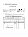
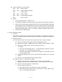
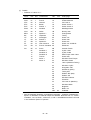
11.4 Alarm/Error Indications
The following table summarizes LED indications during alarm states.
11.4.1 Recoverable Alarms
LED
Alarm
Alarm
Menu
SEL
Quiet 10CPI 12CPI 15CPI 17CPI 20CPI PROP
HSD UTILITY
Paper End
✩
Paper Lever
✩
Paper Jam*
Head Tmp.
✩
SPACE & LF
Motor Tmp.
✩
*Note: Paper jam alarm
o
o
o
o
: LED turns ON.
: LED flashes (200ms ON, 200ms OFF).
: LED flashes (400ms ON, 400ms OFF).
✩
: LED maintains current state.
Blank : LED turns OFF.
Paper jam
Loading paper jam
Ejecting paper jam
Reverse feed paper jam
11 – 5
NLQ
SSD
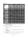
• Fatal alarms
LED
Alarm
Alarm Menu
SEL
Queit 10CPI 12CPI 15CPI 17CPI 20CPI PROP
HSD UTILITY NLQ
Fatal alarms
Printer
internal RAM
S-I/F internal
RAM
S-I/F internal
connection
PRG ROM
S-I/F ROM
EEROM
WDT
NMI
BRK
instruction
Printer
external RAM
S-I/F external
RAM
SPACING
HOMING
Print Head A/D
error
Print Head Gap
AD error
: LED turns ON.
: LED flashes (200ms ON, 200ms OFF).
: LED flashes (400ms ON, 400ms OFF).
: LED maintains current state.
Blank : LED turns OFF.
✩
11 – 6
SSD
11.5 Secondary Switch Functions
11.5.1 MENU
1)
Overview
Features selected in MENU mode become the default features for the printer each time
it is powered on. The Menu function allows the ability to activate features without the use
of software commands. Software commands will override MENU settings.
2)
Key functions
Key Name
GROUP
Function
General categorization of functions/features.
Selects next GROUP title, once through the entire list, loops back to
the first GROUP.
Also, upon first entering MENU, causes the first line of MENU to be
printed.
ITEM
Direct name of functions/features.
Selects next ITEM title, once through the entire list, loops back to the
first ITEM in the current GROUP.
Also, upon first entering MENU, causes the first line of MENU to be
printed.
SET
Value (setting) of the ITEM.
Selects next SETTING value, once through the entire list, loops back
to the beginning of the list.
Also, upon first entering MENU, causes the first line of MENU to be
printed.
PRINT
Prints entire MENU and loops back to the beginning of MENU.
Note: Pressing these keys while the SHlFT key is pressed, selects the items in reverse
order.
3)
Operation description
(a)
To enter Menu mode, depress SHIFT + MENU switch.
1.
MENU mode LED = on
2.
printer = deselected state
3.
SEL LED = off
(b)
Upon entering Menu mode, press the GROUP key, ITEM key, or SET key to print
the first line of MENU. Press the PRINT key to print the whole MENU.
(c)
See Key functions above for description of operation within Menu mode.
(d)
To exit MENU mode, press the SHIFT + MENU.
(e)
If conflicting features/functions are set in menu mode, the printer will treat these
function/features according to the priority table.
(f)
The TOF position is not affected by MENU mode. (When the page length is changed,
be sure to set the TOF.)
(g)
Depressing the FF and TEAR keys or the SEL and LF keys simultaneously while
powering on the printer will reset the menu back to its factory defaults. (See FACTORY
SETTINGS for further details.)
(h)
If the Operator Panel is set to “Limited Operation”, press the SHIFT + MENU switch
during power-up in order to enter MENU.
Note: When first entering Menu mode, the user is not prompted “MENU PRINT” or upon
exiting the user in not prompted “MENU END”.
11 – 7
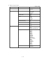
4)
Table of all menu choices
* Factory default
Group
Printer Control
Font
Symbol Sets
Item
Sets
Emulation Mode
IBM PPR *
Epson FX
ML
Print Mode
Utility *
NLQ Courier
NLQ Gothic
DRAFT
DRAFT Mode
HSD*
SSD
Pitch
10CPI*
12 CPI
15 CPI
17.1 CPI
20 CPI
Proportional Spacing
No*
Yes
Style
Normal*
Italics
Size 1)
Single*
Double
Character Set
Set I
Set II*
Standard, Line Graphics, Block
Graphics (ML Mode only)
Language Set
ASCII*
French
German
British
Danish I
Swedish
Italian
Spanish I
Japanese
Norwegian
Danish II
Spanish II
Latin American
French Canadian
Dutch
TRS80
Swedish II
Swedish III
Swedish IV
Turkish
Swiss I
Swiss II
Publisher
Zero Character
Slashed
Unslashed*
11 – 8
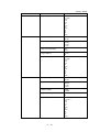
* Factory default
Group
Symbol Sets
Rear Feed
Item
Sets
Code Page
USA*
Canada French
Multilingual
Portugal
Norway
Slashed Letter 0
No*
Yes
Turkey
Greek_437
Greek_869
Greek_928
Greek_437 CYPRUS
Polska Mazovia
Serbo Croatic I
Serbo Croatic II
ECMA-94
Hungarian CWI
Windows Greek
Windows East Europe
Windows Cyrillic
East Europe Latin II-852
Cyrillic I-855
Cyrillic II-866
Kamenicky (MJK)
ISO Latin 2
Hebrew NC (862)
Hebrew OC
Turkey_857
Latin 5 (Windows Turkey)
Windows Hebrew
Ukrainian
Bulgarian
ISO Latin 6 (8859/10)
Windows Baltic
Baltic_774
Line Spacing
6 LPI*
8 LPI
Form Tear-Off 5)
Off*
500ms
1 sec
2 sec
Skip Over Perforation
No*
Yes
Page Width 4)
13.6" *
8"
11 – 9
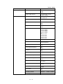
* Factory default
Group
Item
Sets
Rear Feed
Page Length
11"
11 2/3"
12" *
14"
17"
3"
3.5"
4"
5.5"
6"
7"
8"
8.5"
Bottom Feed
Line Spacing
6 LPI *
8 LPI
Form Tear-Off 5)
Off *
500ms
1 sec
2 sec
Skip Over Perforation
No *
Yes
Page Width 4)
13.6" *
8"
Page Length
11"
11 2/3"
12" *
14"
17"
3"
3.5"
4"
5.5"
6"
7"
8"
8.5"
Line Spacing
6 LPI*
8 LPI
Form Tear-Off 5) 6)
Off *
500ms
1 sec
2 sec
Bottom Margin
Valid *
Invalid
Page Width 4)
13.6" *
8"
Page Length
11"
11 2/3" *
12"
14"
17"
3"
3.5"
4"
5.5"
6"
7"
8"
8.5"
Top Feed
11 – 10
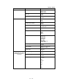
* Factory default
Group
Top Feed
Set-Up
Item
Sets
Wait Time
500ms
1 sec *
2 sec
Page Length Control
by Actual Page Length *
by Menu Setting
Graphics
Bi-directional *
Uni-directional
7 or 8 Bits Graphics 7)
8
7 *
Receive Buffer Size 2)
1 Line
16K *
28K
Paper Out Override
No *
Yes
Print Registration
0.25
0.20
0.15
0.10
0.05
0 *
0.05
0.10
0.15
0.20
0.25
mm
mm
mm
mm
mm
Right
Right
Right
Right
Right
mm
mm
mm
mm
mm
Left
Left
Left
Left
Left
7 or 8 Bits Data Word
8 *, 7
Operator Panel Function 3)
Full Operation *
Limited Operation
Reset Inhibit
No *
Yes
Print Suppress Effective
No
Yes *
Auto LF
No *
Yes
Auto CR 8)
No *
Yes
CSF Bin Select 9)
Bin 1 *
Bin 2
Print DEL Code 7)
No *
Yes
Sl Select Pitch (10 CPI) 8)
15 CPI
17.1 CPI *
Sl Select Pitch (12 CPI) 8)
12 CPI *
20 CPI
Time Out Print
Valid *
Invalid
Auto Select
No *
Yes
Centering Position
DEFAULT *, MODE1, MODE2
CSF Type
Wide *, Narrow
11 – 11
* Factory default
Group
Parallel I/F
Serial I/F
CSF Bin 2
(Selectable only when
the double bin CSF is
mounted)
Item
Sets
I-Prime
Invalid
Buffer Print *
Buffer Clear
Pin 18
+ 5V *
Open
Auto Feed XT 10)
Valid
Invalid *
Parity
None *
Odd
Even
Serial Data 7/8 Bits
8 Bits *
7 Bits
Protocol
ReadylBusy *
X-ON/X-OFF
Diagnostic Test
No *
Yes
BusyLine
SSD – *
SSD +
DTR
R TS
Baud Rate
9600 BPS *
4800 BPS
2400 BPS
1200 BPS
600 BPS
300 BPS
38400 BPS 12)
19200 BPS
DSR Signal
Valid *
Invalid
DTR Signal
Ready on Power Up *
Ready on Select
Busy Time
200 ms *
1 sec
Line Spacing
6 LPI *
8 LPI
Bottom Margin
Valid *
Invalid
Page Length
11"
11 2/3" *
12"
14"
16.57"
3.5"
4"
5.5"
6"
7"
8"
8.5"
11 – 12
* Factory default
Group
CSF Bin 1
Item
Sets
Line Spacing
6 LPI *
8 LPI
Bottom Margin
Valid *
Invalid
Page Width 4) 11)
13.6" *
8"
Page Length
11"
11 2/3" *
12"
14"
16.57"
3.5"
4"
5.5"
6"
7"
8"
8.5"
Notes: 1) Selects both double width and double height characters OR single width and
single height characters.
2) When “I Line” is selected, the receiving buffer size is set to 256 bytes.
3) When “Limited Operation” is selected, after exiting MENU, only the SEL, LF,
FF, and TEAR switches are valid. PRINT QUALITY, PITCH, PARK, and TOF/
Quiet are invalid. This means that MENU mode will not be able to be accessed
via the SHIFT + MENU switch. In order to enter MENU, when the Operator
Panel is set to “Limited Operation”, depress the SHIFT + MENU switch while
powering on the printer. Once in MENU, the Operator Panel can be returned
to “Full Operation” if so desired.
4) When “Page width 8” is selected on the ML321 Turbo, the character printing
wid th per line is set to 8 inches.
5) With Form Tear Off function “on”, if the printer is idle for a few moments
(approx. 0.5, 1, 2 sec.), the paper is forward advanced, from the current print
position, to the tear bar position. If more data is received and processed by
the printer, the paper is then automatically reversed fed back to the original
printing position.
6) Displayed only for roll paper is connection.
7) Displayed only for ML emulation.
8) Displayed only for IBM emulation.
9) Displayed only for CSF (Double Bin) connection.
10) Displayed only for EPSON emulation.
11) Common to Bin, 1 and Bin 2.
12) Displayed only for serial I/F board mounting with F/W for 38400 BPS.
11 – 13
11.5.2 Sample Print Self-test
1)
Start
Depress and hold the LF switch, while moving the power switch to the “on “ position.
2)
Stop
Depress SEL switch.
The printer will finish printing current line before stopping and returning to its default state.
3)
Print header
At the beginning of Self Test, the product description header will be printed as follows
aaaaa
bbb
E
F/W ee.ff
YR gggg-hhhh-ii
CG jj. kk
... as defined by ...
Position & Char. Count
aaaaa
4)
Description
Data Printed
Model name
Comments
ML3320
Narrow chassis
ML3321
Wide chassis
bbb
Compatibility
MIE
ML/EPSON/IBM compatible
ee.ff
Revision #
00.00-99.99
Firmware revision
gggg
ROM Type
4110
hhhh
Part Number
3049
ii
Part Number
01-99
ROM-FD Number
jj.kk
Revision #
00.00-99.99
CG revision
Test pattern
The test pattern is the consecutive printing of all ASCII characters (20H to 7EH) in all print
mode combinations with their corresponding pitches and is the same for all models.
HSD
10, 12, 17.1 CPI
UTL
NLQ
10, 12, 17.1 CPI
10, 12 CPI
NLQ
10 CPI DH/DW (Note 1)
• Number of Characters Printed per Line
CPI
5
10
(Note 1)
Narrow
40
80
Wide
40
80
12
96
96
17.1
137
137
Scalable font in case of the optional ROM.
11 – 14
5)
Operator panel display
While in the Self Test mode ...
6)
(a)
MENU mode LED = off
(b)
SEL LED = off
(c)
CPI LEDs = change when CPI changes
(d)
Print Quality LEDs = change when Print Quality changes
Communication interface
Printer is in the deselect state.
Data cannot be received during self test mode.
11.5.3 Rolling ASCII Self-test
1)
Start
Depress and hold the QUIET/TOF switch, while moving the power switch to the “on”
position.
2)
Stop
Stop the test by depressing the SEL switch.
3)
Print header
a.
Header:
aaaaa
bbb
E
F/W ee.ff
YR gggg-hhhh-ii
CG jj. kk
... as defined by ...
Position & Char. Count
4)
Description
Data Printed
Comments
aaaaa
Model name
ML3320
ML3321
Narrow chassis
Wide chassis
bbb
Compatibility
MIE
ML/EPSON/IBM compatible
ee.ff
Revision #
00.00-99.99
Firmware revision
gggg
ROM Type
4110
hhhh
Part Number
3049
ii
Part Number
01-99
ROM-FD Number
jj.kk
Revision #
00.00-99.99
CG revision
Test pattern
(a)
Printing features/modes = Current Menu value.
(b)
Pattern will be continuous printed of all ASCII characters. (20H to 7EH)
11 – 15
(c)
Number of Characters Printed per Line
CPI
Narrow
Wide
Note 1)
10
80
136
(80)
12
80
136
(80)
17.1
20
80
80
136
136
(80)
(80)
Note 1)
5)
When the Page width of the menu is set to 8 inches.
Operator panel display
While in the Self Test mode ...
6)
(a)
MENU mode LED = off
(b)
SEL LED = off
(c)
CPI LEDs = Current Menu value
(d)
Print Quality LEDs = Current Menu value
Communication interface
Printer is in the deselect state.
Data cannot be received during Rolling ASCII Self-test mode.
11.5.4 Hex-dump
1)
Overview
This mode allows the user to diagnose problems in their program or application by printing
the hexadecimal and ASCII equivalent number of the data that was sent to the printer.
Normally, this data is interpreted by the printer to be a command or printable character,
however in this mode, all data is just converted to the hex and ASCII equivalent and printed
in the “Hex-Dump” format.
2)
Operation method
(a)
Start
Depress and hold the SEL and FF switches simultaneously, while moving the power
switch to the “on” position.
(b)
Stop
Move the Power switch to the “OFF “ or press the Reset switch.
(c)
Print pattern
Hex equivalent of received data
ASCII equivalent
Hex Data Dump
< LF>
XX XX XX XX XX XX XX XX XX XX XX XX XX XX XX XX ................. ..................
XX XX XX XX XX XX XX XX XX XX XX XX XX XX XX XX ................. ..................
XX XX XX XX XX XX XX XX XX XX XX XX XX XX XX XX ................. ..................
.
.
.
etc.
Note 1 : All ASCII control codes are printed as an period “.”.
11 – 16
(d)
ASCII equivalent of incoming data
00H — 1FH
= ASCII “period”
20H — 7EH
= normal ASCII equivalent
7FH
= ASCII “period “
80H — 9FH
= ASCII “period”
A0H — FEH = normal ASCll equivalent
FFH
(e)
= ASCII “period”
Details
1.
Printing features/modes = Utility/10 CPI.
2.
This function operates with both the serial and parallel communication interfaces.
3.
When using cut-sheet paper, printing will stop 1 line from the bottom edge of the page.
Hex-dump print action is initiated when more than 16 bytes of data is received (one
full Hex-dump print line). If less than 16 bytes of data is received, the data will be
printed automatically after a “time out” condition is detected (approximately 150 ms).
5.
HEX dump prints bidirectionaly.
11.5.5 Auto Park/Insert Sheet
1)
Overview
This function allows the user to easily switch from printing on conditions form paper, to
printing on cut-sheet paper without removing the continuous form paper from the printer.
2)
Operation method
(A) Procedure to park the continuous-form paper and insert a single cut-sheet.
(a)
Tear the continuous-form paper using the integrated tear bar.
(b)
Make sure the SHIFT + MENU switch is set to “PRINT” mode not “MENU “ mode.
(c)
Depress the PARK switch. This will cause the printer to ...
a. deselect
b. check the rear-feed paper switch ... if rear-feed paper is detected, continue
with step “c”, if not rear-feed, abort function.
c. retract (reverse feed) the continuous-forms paper out of the platen, but not
out of the push tractor.
(d)
Move Paper Release Lever from the continuous-forms position, to the cut-sheet
position.
(e)
Place the cut-sheet paper (using the paper guide)
(B) Steps to return to continuous-form paper.
(a)
After the cut-sheet page is ejected from the printer, move the Paper
Release Lever from the cut-sheet position, to the continuous-forms position.
(b)
Press the FF/LOAD switches simultaneously.
This will cause the printer to ...
a. high speed skip the print head to the center of the paper
b. feed continuous-form paper from the push tractor, over the paper switch,
and on to the paper load position.
11 – 17
3)
Details
(a)
After the 1st piece of cut-sheet paper is fed out of the printer (by normal printing
operation) the 2nd piece of cut sheet paper can be inserted by using steps a-e.
(b)
The TOF can be adjusted by simultaneously pressing the LF and SHIFT switches
or the FF and SHlFT switches. (paper must be in the tear-off position)
SHIFT + LF = reverse fine LF (1/144 inch)
SHIFT + FF = forward fine LF (1/144 inch)
(Pressing the QUIET and PARK switches or FF and TEAR switches
simultaneously while powering on the printer will reset the TOF to the factory
default position.)
11.5.6 Form Tear-off
1)
Overview
Forms Tear-off allows the user to tear off the fan fold paper at any desired position by
automatically advancing the paper to the cutting edge of the front access cover. The printer
performs up and down operations alternately when the TEAR switch is pressed.
2)
Operation method
(a)
(b)
Conditions:
(1)
Continuous form paper is loaded, paper release lever set to tractor feed.
(2)
Menu is set to Form Tear-off = 500 ms, 1 sec, 2 sec.
(The function is enabled even when the TEAR switch is “OFF. “)
Tear Position:
(1)
Use Auto-Loading of continuous form paper.
(2)
Adjust to desired Tear-off length using fine LFs. (paper must be in the tear-off
position)
SHIFT + LF = Reverse Fine LF.
SHIFT + FF = Forward Fine LF.
(depress the QUIET + PARK or FF + TEAR switch while powering on the
printer to reset the TOF to the factory default position)
3)
Details
(a)
Paper will advance to Tear-off position approximately 500 ms, 1 sec, 2 sec after
printing.
(b)
When data is received by the printer, or SEL switch is pressed to select the printer,
the paper will retract to the user defined printing position.
11 – 18
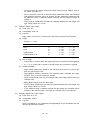
12. COMMAND DESCRIPTION
12.1 Horizontal Control
1)
Carriage return—execute
(a)
Code: CR
(b)
Compatibility: EPS FX/IBM III/ML
(c)
Function:
Initiate printing action; print data in the print buffer by causing a print block change
and set the next printable data’s print position to the left margin.
(d)
Additional details:
• If Auto-LF is activated, a CR will also cause a LF to execute. This action will take
place if there is, or if there is not data in the print buffer.
• The text feature, “Double Wide (expanded)—one line only”, designated by SO and
ESC SO (Epson mode only) will be reset since the “CR” terminates the current
print line.
2)
Backspace
(a)
Code: BS
(b)
Compatibility: EPS FX/IBM lll
(c)
Function:
Print the data in the print buffer and move the printhead one current character width
to the left.
(d)
Additional details:
• Size (distance) of the BS are as follows:
BS + DBL-Width → double width BS
BS + char. pitch → BS the amount of the current char. pitch
BS + Inter-char clearance → BS normal char width + clearance
BS + Proportional → causes the print head to backspace a 10 CPI character width.
• If a multipass character (ex. double height characters) is in the print buffer, when
BS is executed, the paper is reverse feed back to the original printing position of
the multipass character, and the character is printed. (Precise printing is not
guaranteed).
• Once the current print position has reached the left margin, BS will be ignored.
(Epson)
• The print head backspaces to the left margin position. (IBM)
• BS + right, center, full justification → BS is ignored.
3)
Backspace
(a)
Code: BS
(b)
Compatibility: ML
(c)
Function:
Move the printhead one current matrix cell width (character cell and Inter-character
clearance columns) to the left.
12 – 1
(d)
Details
• If a multipass character (ex. double height characters) is in the print buffer, when
BS is executed, the paper is reverse feed back to the original printing position of
the multipass character, and the character is printed. (Precise printing position is
not guaranteed).
• If no “printable” data (including “space) has been previously received by the printer,
the BS is ignored.
• If there is character data on a line formed by 12 vertical dots, such as Line
Graphics, and a BS command is executed, the printer performs a line feed to the
printing position of the next data block and prints.
• The left margin is the limit to the positioning of the printhead when multiple BS
commands are executed. Any subsequent BS commands, processed after this limit
is reached, are ignored.
• Regardless of any CPI change in the middle of the print line, the distance that the
printhead moves backward is the same as the width of the matrix cell (which
includes Inter-character clearance columns) of the CPI that was active previous
to the processing of the BS command.
• Backspace does not initiate printing action (block change); it is executed when
character data or a “initiate printing action” command is received.
• BS + DBL-Width → double width BS
• BS + Inter-char clearance → BS normal char width + clearance
BS + Proportional → Current CPI character width without proportional.
4)
Delete
(a)
Code: DEL
(b)
Compatibility: EPS FX
(c)
Function:
Delete the last printable character data in the print buffer.
(d)
Additional details:
• If the data which is to be deleted is a SP code, (20) H or (32) D, one SP code
is deleted by this command.
• If the data which is to be deleted is in bit image graphics, this command is ignored.
• H-TABs are not deleted.
5)
Print direction—select unibidirectional print
(a)
Code: ESC U n
(b)
Compatibility: EPS FX/IBM lll
(c)
Function:
Choose between left-to-right (unidirectional) printing which achieves improved interline print registration, or Bidirectional printing which achieves faster throughput.
(d)
Range:
Unidirectional
Bidirectional
Epson
01H, 31H, 81H, or B1H
00H, 30H, 80H, or B0H
IBM
Odd numbers
Even numbers
12 – 2
(e)
Out of Range:
This command will be ignored if n equals any other values except for the values
mentioned above.
(f)
Additional details:
• Short-Line-Seeking is performed in both unidirectional and bidirectional print modes.
• When the first thermal threshold of the printhead is sensed, the printer automatically
enters unidirectional printing mode.
6)
Print direction—unidirectional print—one line only
(a)
Code: ESC <
(b)
Compatibility: EPS FX
(c)
Function:
For one print line only, choose left-to-right (Unidirectional) printing for improved interline print registration.
(d)
Additional details:
• Subsequent lines will be printed bidirectionally, according to short line logic seeking
priorities.
7)
Print Direction—Uni-directional
(a)
Code: ESC—
(b)
Compatibility: ML
(c)
Function:
Print while moving the carriage from left to right only; used to improve dot alignment
between print lines.
(d)
Details:
• Uni-directional short line seeking is performed.
8)
Print direction—bi-directional
(a)
Code: ESC =
(b)
Compatibility: ML
(c)
Function
Cancel Uni-directional print and return to Bi-directional print for quicker throughput.
(d)
Details:
Bi-directional printing is the power-up default and the normal mode of printing.
9)
Print position—execute print position from left margin
(a)
Code: ESC $ n1 n2
(b)
Compatibility: EPS FX
(c)
Function:
Initiate printing action by starting to print at the position specified from the left margin.
(d)
Range:
• n1 is a decimal number value 0 – 255.
• n2 is a decimal number value 0 – 255.
12 – 3
(e)
Out of range:
Any position specified beyond the right margin is ignored.
(f)
Additional details:
• Dot position = (n1 + n2*256)/60 to the right of the left margin.
• The position specified as n 1 = n2 = 0 is the left margin.
• Physical Upper Limit...
Wide chassis ... (n1 + n2*256)/60" <
= 13.6 (inches) narrow chassis ... (n1 + n2*256)/
60" <
= 8.0 (inches)
• Logical Upper Limit ...
• Absolute Position <
= Right Margin
• No underlines are made in the print line area skipped by the positioning.
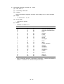
10)
Print position—define print position from Home Position
(a)
Code: ESC % B n1 n2 n3 n4
(b)
Compatibility: IBM III/ML
(c)
Function:
Set the next printing position, by dot columns, absolute to the home position.
• n1 is a decimal number value 48 – 57 (ASCII 0 – 9)
• n2 is a decimal number value 48 – 57 (ASCII 0 – 9)
• n3 is a decimal number value 48 – 57 (ASCII 0 – 9)
• n4 is a decimal number value 48 – 57 (ASCII 0 – 9)
• 0000 <
= n1 n2 n3 n4 <
= Right margin.
RIGHT MARGIN IN UNITS OF DOTS COLUMNS
(e)
CPI
wide chassis
narrow chassis
10
1633
961
12
1959
1153
15
2449
1441
17.1
2798
1646
20
3264
1921
Additional details:
• n1 – n4 is a 4 digit ASCII number; leading zeros must be input even if the number
is less than 1000.
Example: 250 → 0250
• This command will be ignored if print position set by this command exceeds the
right margin or left margin.
• No underlines are made in the print line area skipped by the positioning.
11)
Print position—define right relative position
(a)
Code: ESC% E n1n2n3n4
(b)
Compatibility: ML
12 – 4
(c)
Function:
Moves the next print position by a number of dot columns (specified by n1n2n3n4)
to the right from the current print position.
(d)
Variable range:
n1
n2
(e)
ASCII
Decimal
Hexadecimal
0 – 9
0 – 9
48 – 57
48 – 57
30H – 39H
30H – 39H
n3
0 – 9
48 – 57
30H – 39H
n4
0 – 9
48 – 57
30H – 39H
Out of range:
• If the code for n1n2n3n4 is other than the above, this command is ignored.
(f)
Logical limitation:
• The printer ignores this command if the command attempts to set a print position
exceeding the right margin.
(g)
Additional details:
• The number n1n2n3n4 is a 4-digit decimal number. Since all digits must be defined,
any number that does not use all digits must be padded with leading zeros.
EXAMPLE: 25 → 0025
• If n1n2n3n4 = 0000 is specified, this command is ignored and the printer maintains
the current print position.
• No underlines are printed in the print line areas skipped by this command.
12)
Print position—define left relative position
(a)
Code: ESC % F n1n2n3n4
(b)
Compatibility: ML
(c)
Function:
• Moves the next print position by a number of dot columns (specified by n1n2n3n4)
to the left from the current print position.
(d)
(e)
Variable range:
ASCII
Decimal
Hexadecimal
n1
0 – 9
48 – 57
30H – 39H
n2
0 – 9
48 – 57
30H – 39H
n3
n4
0 – 9
0 – 9
48 – 57
48 – 57
30H – 39H
30H – 39H
Out of range:
• If the code for n1n2n3n4 is other than the above, this command is ignored.
(f)
Logical limitation:
• The printer ignores this command if the command attempts to set a print position
exceeding the left margin.
12 – 5
(g)
Additional details:
• Number n1n2n3n4 is a 4-digit decimal number. Since all digits must be defined,
any number that does not use all digits must be padded with leading zeros.
EXAMPLE: 25 → 0025
• If n1n2n3n4 = 0000 is specified, this command is ignored and the printer maintains
the current print position.
• No underlines are printed in the print line areas skipped by this command.
• When the printer receives a valid n1n2n3n4 number, it prints out the data stored
in the printer buffer.
13)
Print position—define indexed position—by dot column
(a)
Code: ESC\n1 n2
(b)
Compatibility: EPS FX
(c)
Function:
Set the next printing position, by dot columns, indexed from current print position.
(d)
Range:
• n1 and n2 specify a signed 16 bit binary number of dot columns to move; the lower
byte is n1, and the upper byte is n2.
• Range n1 and n2 = 0 – 255
(e)
Logical limitation:
• Value defined beyond the left or right margins are ignored.
(f)
Additional details:
• The new print position is indexed from the current printing position and may be
either to the left or the right of the current position.
• Positive values move the print position to the right and negative values move it
to the left.
• Do position = n1 + n2*256
• Values are shown as follows:
Narrow — FCH, 40H <
= 03H, COH
= n2, n1 <
<
Wide — F9H, A0H = n2, N1 <
= 06H, 60H
• Underlined printing is enabled only when the print head moves to the right.
• A position defined to the left of the current position initiates printing action by
causing a block change.
• The amount of print position can not be deleted by the DEL command.
14)
Print position—define relative dot position
(a)
Code: ESC/n1n2
(b)
Compatibility: IBM III
(c)
Function:
Moves the current logical horizontal print position by n/120 inch from the current print
position.
12 – 6
(d)
Range:
• The number n1 is the low byte and n2 is the high byte in the dot position setting
code.
• The number n1n2 is a decimal number between 0 and 255 (if n1 = n2 = 0 is
specified, the printer maintains the current position).
• Limit
FC40H <
= n1 + n2×256 <
= 03C0H (ML3320)
<
F9A0H = n1 + n2×256 <
= 0660H (ML3321)
(e)
Out of range:
• The printer ignores this command if the command attempts to set a print position
exceeding the left/right margin.
(f)
Additional details:
• Scores can be added only when the print head moves to the right from the current
print position.
• When the print head moves to the left from the current print position, the printer
prints out the data stored in the printer buffer.
15)
Set print position
(a)
Code: ESC DLE @ n A1 A2 P1P2P3P4
(b)
Compatibility: EPSON FX/IBM III/ML
(c)
Function:
Sets the next horizontal print position. The data received after the printer receives
this command is printed out from the new print position.
(d)
Range:
• The number n is used to specify the number of bytes of the parameters which
follow n.
0<
= n<
= 255
• The number A1 is used to specify the type of print position.
0<
= 255
= A1 <
Specify an even number for A1 to specify an absolute print position from the left
margin. Specify an odd number for A1 to specify a relative print position from the
current print position.
• The number A2 is used to specify the direction of movement of the relative print
position.
0<
= A2 <
= 255
Specify an even number for A2 to specify movement toward the right margin
(forward). Specify an odd number for A2 to specify movement toward the left
margin (reverse). The number P1P2P3P4 is used to specify the print position.
• 0<
= P1P2P3P4 <
= 255 (a number between 0 and 9 specified for the lower 4 bits
is valid. The printer ignores the upper 4 bits.) The number P1P2P3P4 should be
specified with a 4-digit decimal number where: P1 = thousands digit, P2 = hundreds
digit, P3 = tens digit, and P1 = units digit.
12 – 7
(e)
Out of range:
• The printer ignores this command if the command attempts to set a print position
exceeding the left/right margin.
(f)
Additional details:
• When the print head moves toward the left margin (reverse) from the current print
position, the printer prints out the data stored in the printer buffer.
Scores can be added when print head movement toward the right margin (forward)
from the current print position is specified while the score mode is set.
16)
Horizontal tabs — define stops — by characters
(a)
Code: ESC D × 1, ×2, ×3 ... xk NUL
(b)
Compatibility: EPS FX/IBM III
(c)
Function:
Set, by character columns, up to a maximum of 32 tab (Epson) or 28 tab (IBM)
positions.
(d)
Range:
• Range k = 1 – 32 (Epson)
= 1 – 28 (IBM)
• Range x = 1 – 255 (Epson)
= 1 – 255 (IBM)
Epson
(e)
IBM
CPI
Wide
Narrow
CPI
Wide
Narrow
10
12
15
17.1
20
135
163
203
233
255
79
95
119
137
159
10
12
15
17.1
20
136
164
204
234
255
80
96
120
138
160
Out of range:
• If k>32 (Epson) or k>28 (IBM) the following value of x will be ignored.
• Maximum x value in each CPI, values larger than maximum are ignored.
(f)
Additional details:
• Tabs are set at every 8 character after powering up the printer, receiving an I
PRIME (INIT) signal or executing an ESC @ (Epson), ESC R (IBM III), ESC } NUL
and ESC { n.
• The entire command string is terminated with a NUL [CHR$(0)] or a number less
than the last tab setting specified. (Epson)
• The tab settings n1, n2, n3 nk must be entered in ascending order.
• Tabs are absolute position. However, if the left margin is changed, HT position
is changed according to the left margin. (IBM)
• Tabs are not reset to default if Left margin is changed. (EPSON)
• If n = 0, clear all tabs set.
• If there is not a nul at the 33rd (Epson)
12 – 8
• This command is disregarded while nk-1 ≤ nk or
character. A maximum of 32 tab stops can be set.
the 29th value of n, this command is disregarded
null character. Tab positions set up to the 28th n
the printer encounters a null
If there is no null character at
until the printer encounters a
value are enabled. (IBM)
Example: If ESC D n1 n2 n4 n3 NUL,
n1 < n2 < n3 < n4 → valid n1 – n4.
n1 < n2 = n3 < n4 → valid n1 – n2 (Epson)
Valid n1, n2, n4 (IBM)
17)
Horizontal tab—execute
(a)
Code: HT
(b)
Compatibility: EPS FX/IBM III
(c)
Function:
Advance from the current print position to the next Horizontal Tab position.
(d)
Additional details:
• Tab positions are based on the character pitch in force at the time the horizontal
tab is set (IBM)
• Tab position is absolute. If the character pitch is changed, including double width,
the tabs will remain in the same absolute locations. (Epson)
• Upon power up the default tabs are set at columns 9, 17, 25, 33 ... and every eight
spaces after that.
• HT will become invalid when it exceeds right margin setting. If an HT is executed
past the right margin, if will cause the next character to be printed immediately
after the last. All subsequent HT’s will correspond to the beginning of the TAB
setting sequence.
• No underline will be come in the “skip” area.
18)
Horizontal tabs—define stops—default values
(a)
Code: ESC R
(b)
Compatibility: IBM III
(c)
Function:
• This command sets horizontal tabs at every 8th position starting at column 9 and
clears all vertical tabs.
19)
Horizontal tabs—define stops—by characters
(a)
Code: ESC, HT X1 Y1 Z1, ... , Xm Ym Zm CR
(b)
Compatibility: ML
(c)
Function:
Clear all previously defined H-tabs and define up to 16 new horizontal tab stop
positions from the left-most physical print position in units of character columns.
12 – 9
(d)
Range:
• Variables
X1
ASCII
Decimal
Hexadecimal
0 – 9
48 – 57
30 – 39
Y1
0 – 9
48 – 57
30 – 39
Z1
0 – 9
48 – 57
30 – 39
m (number of tabs) = 0–16
• Argument “X1Y1Z1”
wide chassis
narrow chassis
(e)
10 cpi
12 cpi
17.1 cpi
20 cpi
136
163
233
272
80
96
137
160
Out of range:
• The command will be ignored.
(f)
Logical limitations:
XmYmZm represents a 3 digit number where each consecutive XmYmZm number
must be greater than the previous one or else Xm Ym Zm is ignored.
X1 Y1 Z1 < X2 Y2 Z2 < ... < Xmax Ymax Zmax
(g)
Details:
• Maximum of 16 HT stops maybe defined.
• Horizontal tab settings can be cleared by:
— ESC HT CR (defining no tabs)
— ESC HT 000 CR (defining no tabs)
— ESC HT 001 CR (defining no tabs)
Note: Tab position “0” and tab position “1” both represented the first column position
on the print line.
• X1 Y1 Z1 is a 3-digit ASCII numeric. A 2-digit or 1-digit X1Y1Z1 number can be
specified, however, by separating it from the subsequent parameters with a comma.
• Upon Power-Up and reset conditions, such as l-Prime, the default tabs are set at
character columns 9, 17, 25, 33 ... and every eight character columns after that.
• Horizontal Tab positions are relative to the character pitch. While in 10 cpi, a Htab of 10 characters will represent a physical distance of 1 (10/10th) inch. This
same 10 character H-tab in 12 cpi will represent a physical distance of 11/12th
of an inch.
• Refer to the Illustration attachments for further details.
20)
Horizontal tabs – define stops – by dot column
(a)
Code: ESC ETX X1 Y1 Z1 W1, ... , Xm Ym Zm Wm CR
(b)
Compatibility: ML
12 – 10
(c)
Function:
Clear all previously defined H-tabs and define up to 16 new horizontal tab stop
positions from the left-most physical print position in units of dot columns.
(d)
Range:
• Variables
ASCII
Decimal
Hexadecimal
X1
0 – 9
48 – 57
30 – 39
Y1
Z1
0 – 9
0 – 9
48 – 57
48 – 57
30 – 39
30 – 39
W1
0 – 9
48 – 57
30 – 39
m (number of tabs) = 0–16
• Argument “x1y1z1w1”
10 cpi
wide chassis
narrow chassis
(e)
12 cpi
17.1 cpi
20 cpi
1,632
1,956
2,796
3,264
960
1,152
1,644
1,920
Out of range:
The command will be ignored.
(f)
Logical limitations:
XmYmZmWm represents a 4 digit number where each consecutive XmYmZmWm
number must be greater than the previous one or else Xm Ym Zm Wm is ignored.
(g)
Details:
• Maximum of 16 HT stops may be defined.
• Each tab must be defined in ascending order.
• Horizontal tab setting can be cleared by:
— ESC ETX CR (defining no tabs)
— ESC ETX 0000 CR (defining no tabs)
— ESC EtX 0001 CR (defining no tabs)
Note: Tab position “0” and tab position “1” both represented the first column position
on the print line.
• X1 Y1 Z1 W1 is a 4 digit ASCII numeric.
• X1Y1Z1W1 should be a 4-digit ASCII number. An X1Y1Z1W1 number of 3-digits
or less can be specified, however, by separating it from the subsequent parameters
with a comma.
• Upon Power-Up and reset conditions, such as l-Prime, the default tabs are set at
columns 97, 193, 289 ... and every 96 dot columns after that.
• Horizontal Tab positions are relative to the character pitch. While in 10 cpi, a Htab of 120 columns will represent a physical distance of 1 inch. This same 120
columns H-tab in 12 cpi will represent a physical distance of 120/144th of an inch.
• H-TABS by dot column are valid when combined with Bit Image Graphics and
Proportional Width Characters.
12 – 11
21)
Horizontal tab—execute
(a)
Code: HT
(b)
Compatibility: ML
(c)
Function:
Advance from the current print position to the next Horizontal Tab position.
(d)
Logical limitations:
• An HT can not be executed beyond the right margin.
(e)
Details:
• HT execution will cause an advance to the next tab stop position defined by the
“H-TAB by characters” or “H-TAB by columns” definition commands; which ever
HT command was most recently defined.
• When character pitch is changed, tab position will be recalculated based on the
new pitch.
• HT will become invalid when it exceeds right margin setting. If an HT is attempted
past the right margin, it will cause the next character to be printed immediately
after the last. All subsequent HT’s will correspond to the beginning of the TAB
setting sequence.
• If the Underline print feature is “on”, the area of the page that the HT skips over
will not be underlined.
22)
Margins—define left margin
(a)
Code: ESC/n
(b)
Compatibility: EPS FX
(c)
Function:
Left margin is set at (n) characters from the left-most physical print position.
(d)
Range:
• Range n = 0 – 255
NAME
Pitch
PICA/PROPORTIONAL
ELITE
COMPRESSED
COMPRESSED ELITE
(e)
Wide
Narrow
10
12
1 – 134
1 – 162
1 – 79
1 – 94
15
1 – 202
1 – 118
17.1
20
1 – 231
1 – 255
1 – 135
1 – 157
Out of range:
• If n exceeds the right margin, the left margin command will be ignored.
(f)
Additional details:
• Left margin positions are based on the character pitch which is in force at the time
the left margin is set. Left Margin’s position is absolute. If the character pitch is
changed, the margin will NOT move to accommodate the change.
• While in proportional mode, the print column width of the margin will be set in pica
character size.
12 – 12
• The left margin will remain at value set unless reset by some software code or
the printer is turned off.
• Input of the ESC/ code with a valid left margin parameter causes the horizontal
TAB positions previously set to be cleared, and the subsequent horizontal TAB
will default to every 8 character positions starting with the new left margin as
position 0.
• There must be a difference of at least 25 character between the left margin and
right margin values for 10 CPI.
23)
Margins—define right margin
(a)
Code: ESC Q n
(b)
Compatibility: EPS FX
(c)
Function:
Right margin is set at (n) characters from the left-most physical print position.
(d)
Range:
• Range n = 1 -255
NAME
(e)
Pitch
Wide
Narrow
PICA
10
2 – 136
2 – 80
ELITE
12
15
3 – 164
3 – 204
3 – 96
3 – 120
COMPRESSED
17.1
4 – 234
4 – 138
COMPRESSED ELITE
20
4 – 255
4 – 160
Out of range:
• The number “n” must be within the ranges given above, otherwise it will be ignored.
• If n = 0, or is less than or equal to the left margin this command is ignored.
(f)
Additional details:
• Right margin positions are based on the character pitch which is in force at the
time the right margin is set.
• Right Margin’s position is absolute. If the character pitch is changed, the margin
will NOT move to accommodate the change.
• While in proportional mode, the print column width of the margin will be set in pica
character size.
• Setting Right margin clears the print buffer.
• There must be a difference of at least 25 character between the left margin and
right margin values for 10 CPI.
• If you attempt to print a character beyond the right margin the character will be
printed on the next line after a line feed and carriage return are executed.
24)
Margins—define left & right margin
(a)
Code: ESC X n1 n2
(b)
Compatibility: IBM III
(c)
Function:
Set the Left Margin to (n1) characters and Right Margin to (n2) characters from the
left-most physical print position.
12 – 13
(d)
Range:
1<
= n1 <
= 255
2<
= n2 <
= 255
• The ranges for n1 and n2 are
n1< n2
(e)
Out of range:
• If n1 or n2 = 0 then the current margin setting is used.
• If n2 exceeds the default range n2 shall be converted to the default value.
10CPI
12CPI
15CPI
17.1CPI
20CPI
136
164
204
234
255
80
96
120
138
160
Wide Column
Narrow Column
(f)
Additional details:
• The default value of the left margin is the 1st character.
• The margin’s positions are absolute. If the character pitch is changed, the margins
will NOT move to accommodate the change.
• Character pitch changes afterwards do not affect the distance from the home
position.
• n1 n2 indicates the left and right edges of printable area. For example if n1 = 10,
n2 = 100, a printable area is from the 10th column to the 100th column: 91
characters are printable.
25)
Print-Line justification—select
(a)
Code: ESC a n
(b)
Compatibility: EPS FX
(c)
Function:
The text position/alignment will be set according to one of the four given modes
assigned by n. (n is Binary value)
(d)
Range:
n
Justification
0
1
Left
Center
2
Right
3
Full
(e) Additional details:
• n = 0 Left justification is the default or standard format, in which the left margin
is even and the right margin is not.
• n = 1 The centering command centers a line of text between the margins. This
command is used for headings, titles and captions.
• n = 2 Right justification is the opposite of left justification. The right margin is even
and the left is not.
12 – 14
• n =3 Full justification puts extra spaces where necessary so that both the left and
right margins are aligned.
• Full justification (n = 3) is performed when the printer receives (at the time when
printing starts) data exceeding 75% of the maximum number of characters to be
printed in a line.
• Print position will be affected by the commands which set the left/right margin.
• This command causes a print block change. If there is data in the print buffer and
this command is sent, the data will be printed before the justification takes affect.
Note: When you use the Auto Justification, use carriage returns at the end of
paragraphs only, not at the end of each line of text.
26)
Margins—define left margin
(a)
Code: ESC % C n1 n2 n3
(b)
Compatibility: ML
(c)
Function:
Define the logical left-most printing position limitation from the left most-physical print
position in units of 1/120 inch.
(d)
Range:
• Variable
ASCII
Decimal
Hexadecimal
n1
0 – 9
48 – 57
30 – 39
n2
0 – 9
48 – 57
30 – 39
n3
0 – 9
48 – 57
30 – 39
• Argument “n1n2n3”
narrow chassis 000-900 × 1/120 inches (approx. 7.5 inches max.)
wide chassis
000-999 × 1/120 inches (approx. 8.3 inches max.)
(e)
Out of range:
• If any digit is out of range, the command is ignored.
(f)
Logical limitation:
• If n1n2n3 exceeds the maximum value, the command will also be ignored.
• Set number difference between right margin and left margin must be a minimum
of 60, otherwise the command will be ignored.
(g)
Details:
• n1n2n3 is a 3 digit ASCll number. Since all digits must be defined, any number
that does not use all digits must be padded with leading zeros.
EXAMPLE: 8 → 008.
• When n1n2n3 = 000, the command will be ignored.
• When n1n2n3 = 001, the left margin will be cleared.
• If the left margin is defined after one or more characters have been sent to the
current print line, the left margin will not become valid for the current print line,
but will be valid on the next print line.
12 – 15
27)
Margins—right margin
(a)
Code: ESC % R n1 n2 n3 n4
(b)
Compatibility: ML
(c)
Function:
• Define the logical right-most printing position limitation from the left most-physical
print position in units of 1/120 inch.
(d)
Range:
Variable
ASCII
Decimal
Hexadecimal
n1
0 – 9
48 – 57
30 – 39
n2
n3
0 – 9
0 – 9
48 – 57
48 – 57
30 – 39
30 – 39
n4
0 – 9
48 – 57
30 – 39
• Argument
narrow chassis
(e)
wide chassis
w/o Left Margin
60 < RM <
= 960
60 < RM <
= 1632
w/ Left Margin
LM + 60 <
= RM <
= 960
LM + 60 <
= RM <
= 1632
Out of range:
If any variable is out of range, the command is ignored and any subsequent variables
are interpreted as normal data.
(f)
Logical limitation:
• The Right Margin can not be defined within 60/120 inch (1/2 inch) from the Left
Margin or can not be defined to the left of the Left Margin. If this is attempted the
command will be ignored.
(g)
Details:
• n1n2n3n4 is a 4 digit ASCII number. Since all digits must be defined, any number
that does not use all digits must be padded with leading zeros.
EXAMPLE: 8 → 0008.
• When n1n2n3n3 = 0000, the Right Margin will be set to the default value.
• Explanation of illegal variable results (n2 = out of range):
ESC % R n1 n2 n3 n4
n3 and n4 interpreted as normal data
command is aborted
• If the right margin is defined after one or more characters have been sent to the
current print line, the right margin will not become valid for the current print line,
but will be valid on the next print line.
12 – 16
12.2 Vertical Control
1)
Line spacing—select fixed amount—1/6 inch
(a)
Code: ESC 2
(b)
Compatibility: EPS FX
(c)
Function:
Set the line spacing to 1/6 inch units.
(d)
Additional details:
• This command will remain in effect until a new line spacing command is sent to
the printer.
• This command does not set the top of form position.
• LF, VT, or CR (if Auto F is on) execute in units of 1/6 inch when this function is
active.
(e)
Related functions:
• LF, VT, CR (and Auto LF)
6 LPI (Lines per inch):
0
1
2
3
4
5
6
1/6 inch (24/144 inch)
7
8
9
10
11
12
13
14
15
16
17
18
19
12 – 17
2)
Line spacing—select fixed amount—1/6 inch
(a)
Code: ESC 6
(b)
Compatibility: ML
(c)
Function:
Set the line spacing to 1/6 inch units (6 LPI).
(d)
Details:
• This command remains in effect until a new line spacing command is sent to the
printer.
• This command does not set the top of form position.
• LF, VT, or CR (if Auto LF is on) execute in units of 1/6 inch when this function
is active.
• Refer to the illustration attachments for further details.
(e)
Related functions:
• LF, VT, CR (and Auto LF)
6 LPI (Lines per Inch):
0
1
2
3
4
5
6
1/6 inch (24/144 inch)
7
8
9
10
11
12
13
14
15
16
17
18
19
12 – 18
3)
Line spacing—select fixed amount—1/8 inch
(a)
Code: ESC 0
(b)
Compatibility: EPS FX/IBM III
(c)
Function:
Set the line spacing 1/8 inch units.
(d)
Additional details:
• This command remains in effect until a new line spacing command is sent to the
printer.
• This command does not set the top of form position.
• LF, VT, or CR (if Auto LF is on) execute in units of 1/8 inch when this function
is active.
(e)
Related functions:
• LF, VT, CR (and Auto LF)
8 LPI (Lines per Inch):
0
1
2
3
4
1/8 inch (18/144 inch)
5
6
7
8
9
10
11
12
13
14
15
16
12 – 19
4)
Line spacing—select fixed amount—1/8 inch
(a)
Code: ESC 8
(b)
Compatibility: ML
(c)
Function:
Set the line spacing to 1/8 inch units (8 LPI).
(d)
Details:
• This command remains in effect until a new line spacing command is sent to the
printer.
• This command does not set the top of form position.
• LF, VT, or CR (if Auto LF is on) execute in units of 1/8 when this function is active.
(e)
Related function
• LF, VT, CR (and Auto LF)
8 LPI (Lines per Inch):
0
1
2
3
4
1/8 inch (18/144 inch)
5
6
7
8
9
10
11
12
13
14
15
16
12 – 20
5)
Line spacing—select fixed amount—7/72 inch
(a)
Code: ESC 1
(b)
Compatibility: EPS FX/IBM III
(c)
Function:
Set the line spacing to 7/72 inch units.
(d)
Additional details:
• This command remains in effect until a new line spacing command is sent to the
printer.
• This command does not set the top of form position.
• LF, VT or CR (if Auto LF is on) execute in units of 7/72 inch when this function
is active.
(e)
Related functions:
• LF, VT, CR (and Auto LF)
6)
Line spacing—define amount—n/72 inch
(a)
Code: ESC A n
(b)
Compatibility: IBM III
(c)
Function:
Stores the line feed amount in 1/72-inch units.
(d)
Range:
Range n = 0 – 255
(e)
Out of range:
Not applicable—cannot receive value larger than 255 (FFH).
(f)
Additional details:
• If n = 0, the line feed amount is 0 and subsequent print-line will overprint over the
same print-line.
• This command does not set the top of form position.
• The ESC 2 command sets the line feed amount stored by this command.
7)
Line spacing—define amount—n/72 inch
(a)
Code: ESC An
(b)
Compatibility: EPS FX
(c)
Function:
Sets the line spacing to n/72 inch.
(d)
Range:
Range n= 0 to 85, n = 128 to 213 (Bit 7 of the n code is invalid.)
(e)
Out of range:
Value of n not within the allowable range will be ignored.
(f)
Additional details:
• If n = 0, the line feed amount is 0 and subsequent print-lines will overprint over
the same print-line.
• This command does not set the top of form position.
• Power on default or the I-Prime signal resets the LF unit to the current MENU value.
12 – 21
8)
Line spacing—define amount—n/216 inch
(a)
Code: ESC 3 n
(b)
Compatibility: EPS FX/IBM III
(c)
Function:
Sets line spacing to n/216 inch.
(d)
Range:
• Range n = 0 – 255 (Epson), n = 1 – 255 (IBM)
(e)
Additional details:
• If n = 0, the line feed amount is 0 and subsequent characters will overprint over
the same print-line. (Epson) If n = 0 is specified, this command will be invalid and
the previously set line feed amount remains effective. (IBM)
• This command does not set the top of form position.
• Power on default or the I-Prime signal resets the LF unit to the current MENU value.
• LF, VT, or CR (if Auto LF is on) execute in units of n/72 inch when this function
is active.
(f)
Related functions:
• LF, CT, CR (and Auto LF)
9)
Line spacing—activate amount defined by n/72 inch
(a)
Code: ESC 2
(b)
Compatibility: IBM III
(c)
Function:
Activate the line feed amount defined by the ESC A “n” command.
(d)
Details:
• If no ESC A n sequence has been defined, the line spacing amount will be
according to current MENU value.
(e)
Related functions:
• ESC A n
10)
Line feed—execute amount—n/216 inch
(a)
Code: ESCJ n
(b)
Compatibility: EPS FX/IBM III
(c)
Function:
Execute a n/216 inch line feed without changing the current stored line spacing value.
(d)
Range:
• Range n = 0 – 255 (Epson), n = 1 – 255 (IBM)
(e)
Additional details:
• The printer prints the contents of the buffer without a carriage return. (Epson)
Moves the current print position to the print start position of next line (left margin
position) when the “Auto CR” feature is set to “Yes” in MENU mode. (IBM)
• This command does not need a cancel code, since it is executed only once.
• No feed is performed when n = 0. (Epson)
If n = 0 is specified, this command will be invalid. (IBM)
12 – 22
(f)
Related functions:
• This command does not clear the elongated character mode (double width printed
character) selected by ESC SO or SO code.
11)
Fine LF—execute—n/144 inch amount
(a)
Code: ESC % 5 n
(b)
Compatibility: EPS FX/IBM III/ML
(c)
Function:
Initiate printing action; print data in the print buffer by causing a print block change
and execute a n/144 inch line feed, then a carriage return.
(d)
Range:
n1
Decimal
Hexadecimal
0 – 255
00 – FF
The eight bit (b7) is ignored so the effective range of n1 is as follows ...
(e)
Decimal
Hexadecimal
n1
0 – 127
128 – 255
00 – 7FH
80 – FFH
0 – 127 (0/144” – 127/144”)
Out of range:
Not applicable, can not receive a value larger than 255 (FF)H or smaller than 0.
(f)
Details:
• If n1 = 0 the line spacing will be set to a distance of zero, upon execution of a
LF.
• If the line spacing is set to zero (n1 = 0), no paper feeding will occur when a LF
is executed, but any data in the print buffer will be printed (just as if only a CR
was executed.)
12)
Line spacing—define amount—n/144 inch
(a)
Code: ESC % 9 n1
(b)
Compatibility: EPS FX/IBM III/ML
(c)
Function:
Set the line spacing to n/144 units.
(d)
Range:
n1
Decimal
Hexadecimal
0 – 255
00 – FF
The eight bit (b7) is ignored so the effective range of n1 is follows ...
(e)
Decimal
Hexadecimal
n1
0 – 127
128 – 255
00 – 7FH
80 – FFH
0 – 127 (0/144” – 127/144”)
Out of range:
Not applicable, can not receive a value larger than 255 (FF)H or smaller than 0.
12 – 23
(f)
Details:
• If n1 = 0 the line spacing will be set to a distance zero, upon execution of a LF.
• If the line spacing is set to zero (n1 = 0), no paper feeding will occur when a LF
is executed, but any data in the print buffer will be printed (just as if only a CR
was executed).
13)
Line feed—execute forward LF with CR
(a)
Code: LF
(b)
Compatibility: EPS FX/IBM III
(c)
Function:
Initiate printing action; print data in the print buffer by causing a print block change
and execute a line feed, then a carriage return. Moves the current print position to
the print start position of next line (left margin position) when the “Auto CR” feature
is set to “Yes” in MENU mode. (IBM)
(d)
Additional details:
• Line spacing pitch will be set by ESC A n, ESC 0, ESC 2, ESC 3 n, ESC 1, ESC
% 9 n. Otherwise, the LF pitch will be set by the current MENU when power is
on or I-Prime signal is received.
• This code will cancel enlarged character mode set by the ESC SO (Epson mode
only) and SO code before the LF code or only spaces before this code, only line
feed is performed.
14)
Line feed—execute reverse LF
(a)
Code: ESC j n
(b)
Compatibility: EPS FX
(c)
Function:
Execute an immediate n/216 inch reverse line feed; which will be executed only once
each time this command is sent.
(d)
Range:
• Range n = 0 – 255
(e)
Additional details:
• It is not recommended to use the pull tractor feed unit when reverse line feeds
are required.
• The current line spacing will not be changed.
15)
Line feed—execute reverse LF—one line only
(a)
Code: ESC ]
(b)
Compatibility: IBM III (Hidden command for user)
(c)
Function:
Execute the current LF pitch, reverse line feed; which will be executed only once each
time this command is sent.
(d)
Additional details:
• It is recommended to use the pull tractor feed unit when reverse line feeds are
required.
• The current line spacing will not be changed.
12 – 24
16)
Line feed—execute forward LF with CR
(a)
Code: LF
(b)
Compatibility: ML
(c)
Function:
Initiate printing action; print data in the print buffer by causing a print block change
and execute a line feed, then a carriage return.
(d)
Details:
• This command is equivalent to the composite command (ESC.?.N:) where
n = (23) H
• The line spacing is set by ESC.6, ESC.8 or ESC.%.9.n command. The line spacing
will be set to the default line pitch after a default sequence (power up, I-Prime,
and CAN.)
17)
Line feed—execute reverse line feed
(a)
Code: ESC LF
(b)
Compatibility: ML
(c)
Function:
Initiate printing action; print data in the print buffer by causing a print block change
and execute a reverse line feed and then a carriage return for one line only.
(d)
Details:
• Composite command (ESC.?.n.:) for CR/LF will perform.:
n = (31)H Reverse Line Feed
• When continuous paper or single sheets (fed by the SASF function) are used,
unlimited number of reverse LFs may be executed.
• When the CSF is attached to the printer the Reverse LF command will be valid
for 1/3 inch (48/144 inch) in order to prevent paper jams.
18)
Line feed—automatic LF—ON/OFF
(a)
Code: ESC 5 n
(b)
Compatibility: IBM III
(c)
Function:
Enables/disables the automatic Line Feed. The printer performs an automatic LF
each time it receives a carriage return (CR).
(d)
Range:
n = 0 – 255
odd numbers = Automatic LF enabled
even numbers = Automatic LF disabled
19)
Line feed—W/O carriage return
(a)
Code: ESC DC2
(b)
Compatibility: ML
(c)
Function:
• Initiate printing action; print data in the print buffer by causing a print block change,
feed the paper the pre-defined line spacing amount, and set the next printable
data’s print position to the last position of the previous line (no CR performed).
12 – 25
20)
Line feed—execute direct skip
(a)
Code: ESC VT n1 n2
(b)
Compatibility: ML
(c)
Function:
• Initiate printing action; print data in the print buffer by causing a block change, feed
the paper the number of lines defined by this command, and set the next printable
data’s print position to the left margin.
(d)
Range:
n1
n2
(e)
ASCII
Decimal
Hexadecimal
0 – 9
0 – 9
48 – 57
48 – 57
30 – 39
30 – 39
Out of range:
The command will be ignored.
(f)
Details:
• If n1 n2 = 00, no paper feeding is performed.
21)
Form length—define amount—by inches
(a)
Code: ESC C nul n
(b)
Compatibility: EPS FX/IBM III
(c)
Function:
Sets the form length to n inches
(d)
Range:
• Range n = 1– 22 (Epson)
1– 255 (IBM)
(e)
Out of range:
• n = 0 or n > 22 (Epson) will last valid setting and ignore the command.
(f)
Additional details:
• This command does not affect vertical tab settings. (IBM)
This command will reset vertical tab settings to their default values. (Epson)
• When this command is valid, it cancels the “Skip Over Perforation” feature even
if the feature has been selected in the MENU mode.
• Top of form position is set by this command.
22)
Form length—define amount—by lines
(a)
Code: ESC C n
(b)
Compatibility: EPS FX/IBM III
(c)
Function:
Sets the form length to n lines length to n lines.
(d)
Range:
• Range n = 1 – 127 (Epson)
1 – 255 (IBM)
12 – 26
(e)
Out of range:
• If n = n > 127 (Epson), bit 7 is cleared and set that value as is.
(f)
Additional details:
• This command does not affect vertical tab settings. (IBM)
This command will reset vertical tab settings to their default values. (Epson)
• Top of form will be set.
• When this command is valid, it cancels the “Skip Over Perforation” feature even
if the feature has been set in the MENU mode.
• The amount of each line defined by this command, is equal to the current LF
spacing defined by ESC 0, ESC 2, ESC A n, ESC 3 n, ESC 1, ESC % 9n.
• If n = 0 or 128 (Epson), this command is treated as ESC C NUL n.
(g)
Related functions:
• ESC 0, ESC 2, ESC A n and ESC 3 n, ESC 1, ESC % 9 n.
23)
Form length—define amount—by 1/2 inch
(a)
Code: ESC G n1 n2
(b)
Compatibility: ML
(c)
Function:
Define the logical form length by the amount of n1n2 × 1/2 inch and set the TOF
position.
(d)
Range:
• Variables
ASCII
Decimal
Hexadecimal
n1
0 – 9
48 – 57
30 – 39
n2
0 – 9
48 – 57
30 – 39
Argument
n1n2 range = 00 – 99
(e)
Out of range:
The command will be ignored.
(f)
Details:
• If n1n2 = 00, the page length will default to the value defined by MENU.
• Maximum form length, 1/2 × 99 = 49.5 inches.
• Factory setting: 1/2 × 22 = 11 inches.
24)
Form length—define amount—by lines
(a)
Code: ESC F n1 n2
(b)
Compatibility: ML
(c)
Function:
• Define the logical form length by number of lines, and set the TOF position.
12 – 27
(d)
Range:
• Variable
ASCII
Decimal
Hexadecimal
n1
0 – 9
48 – 57
30 – 39
n2
0 – 9
48 – 57
30 – 39
Argument
n1 n2 = 00 – 99
(e)
Out of range:
The command will be ignored.
(f)
Details:
• If n1n2 = 00, the page length will default to the value defined by MENU.
• Maximum form length is based upon current LF spacing. If this spacing is set to
144/144 inch (maximum value for line spacing), the maximum form length will be
99 × 1 inch = 99 inches.
• If line spacing defined, by ESC % 9 n, is zero, this command will effectively be
ignored.
ESC % 9 0 = 0 line spacing.
ESC F n1 n2 where n1 n2 = any value.
Line Spacing
Form Length
0×
(any value) = form length.
• This command will set the top of form and the top of VFU.
• Factory setting: 11 inches
25)
Form feed—execute
(a)
Code: FF
(b)
Compatibility: EPS FX/IBM III
(c)
Function:
Prints the data in the print buffer followed by a carriage return, then feeds the paper
to the next TOF position.
(d)
Additional details:
• Factory setting of form length is eleven (11) inches. (MENU)
• Pressing FORM FEED button on the operator panel feeds the paper forward to
the next top of form position.
• A Form feed will be performed to the next top of form position even when the FF
is received at the top of form position.
• Double width by ESC SO (Epson mode only) and SO will be reset.
• Power up or 1 Prime will set TOF.
26)
Form feed—execute
(a)
Code: FF
(b)
Compatibility: ML
12 – 28
(c)
Function:
• Initiate printing action; print data in the print buffer by causing a print block change,
feed the paper the defined form length amount and set the next printable data’s
print position to the left-margin.
(d)
Details:
• Paper length can be set by the ESC F n1 n2 or the ESC G n1 n2 commands.
• Upon power-up, or reception of a reset command, the page length will default to
the value set in MENU.
• Factory setting of Form Length is 11 inches.
27)
Top of form—define
(a)
Code: ESC 5
(b)
Compatibility: ML
(c)
Function:
Define the top of the form (logical page) and the top of the VFU by logically “marking”
the current vertical print position.
(d)
Details:
• This command does not affect the CSF or SASF function.
28)
Margins—define bottom margin (auto skip)
(a)
Code: ESC % S n
(b)
Compatibility: ML
(c)
Function:
Define the size of the area at the bottom of the logical page which will automatically
be skipped over by feeding the paper until the next TOF position.
(d)
Range:
n1
(e)
ASCII
Decimal
Hexadecimal
0 – 9
48 – 57
30 – 39
Out of range:
The command will be ignored.
(f)
Details:
• If n = 0, the Auto-skip function is released.
• The distance that is skipped is twice the value of “n” multiplied by 1/6 inch (6 LPI).
“n” × 2 × 1/6 = Auto-skip distance.
• If Auto-skip (Skip Over Perforation) function is selected in Menu, the distance that
will be skipped is 1 inch.
• When in the Hex-Dump secondary mode, the Auto-skip function will operate
according to the MENU selection.
• Form length and TOF must be set before the Auto-skip area is defined.
• Refer to the illustration attachments for further details.
• Any printing operation which encroaches upon the bottom margin area, such as
LF, Print Data + LF, Print Data + CR will cause the paper to be fed by skip over
area length. On this next page, printing then will resume.
12 – 29
• When the current line spacing is defined by ESC ( (8 LPI) or ESC % 9 n, (n/144
LPI) the auto skip function is performed when the remaining amount of the logical
page is as follows...
Variable
n1
0
1
2
3
4
5
6
7
8
9
inches
(n1 × 2 × 1/6)
Equivalent
no. of 6 LPIs
No. of steps
of the LF motor
Comment
0
2
4
6
8
10
12
14
16
18
0
48
96
144
192
240
288
336
384
432
No skip
Skip
Skip
Skip
Skip
Skip
Skip
Skip
Skip
Skip
0
2/6
4/6
6/6
8/6
10/6
12/6
14/6
16/6
18/6
Logical top of form
Page 1
A
B
Logical bottom of form
C
Skip over perforation area
C
TOF
Description:
Description:
Page 2
Data "C" that encroaches on the
"Skip Over Perf" area is printed
at the next TOF.
12 – 30
Logical top of form
Page 1
A
B
Logical bottom of form
C
Description:
No area of the logical form
is skipped. Data A, B and
C are printed as pictured.
Page 2
29)
Top of form—define
(a)
Code: ESC 4
(b)
Compatibility: IBM III
(c)
Function:
Logically “mark” the current vertical print position.
(d)
Additional details:
• This command does not affect the CSF or SASF function.
30)
Margins—define bottom margin (auto skip)
(a)
Code: ESC N n
(b)
Compatibility: EPS FX/IBM III
(c)
Function:
Sets the skip-over perforation to n lines, according to the current LF value.
(d)
Range:
• Range n = 0 – 127 (Epson)
0 – 255 (IBM)
12 – 31
(e)
Out of range:
<Epson>
• The n value has to be less than the current form length.
If n is equal to or greater than the form length, this function will be ignored.
• If n = 0 or n = 128, the last skip over perforation value will remain as previous
value.
• If n > 127, bit 7 is cleared and length is set to resulting value of 4.
<IBM>
• The n value can be set regardless of paper length. (IBM)
• Not applicable—cannot receive value larger than 255 (FFH).
(f)
Additional details:
• The skip over perforation will be reset by ESC O or page length set command.
• Skip over perforation distance will not be affected by a change in the line pitch.
• Entering to the area of skip over perforation by LF, VT, CR (with LF), ESC J n
and auto line feed will cause the skip over perforation and feed to the top of form.
(g)
Related functions:
• Line length value is based on ESC 0, ESC 2, ESC A n, or ESC 3 n, ESC 1, ESC
% 9 n.
Logical top of form
Page 1
A
B
Logical bottom of form
C
Skip over perforation area
TOF
C
Description:
Description:
Data "C" that encroaches on the
"Skip Over Perf" area is printed
at the next TOF.
Page 2
12 – 32
31)
Margins—cancel bottom margin (auto skip)
(a)
Code: ESC O
(b)
Compatibility: EPS FX/IBM III
(c)
Function:
Cancel Skip-Over Perforation.
(d)
Additional details:
• Skip over perforation is cleared when power down/power up I Prime occurs.
• Skip over perforation is canceled when the form length is changed by the following
codes:
ESC C n and ESC C nul n.
Logical top of form
Page 1
A
B
Logical bottom of form
C
Description:
No area of the logical form
is skipped. Data A, B and
C are printed as pictured.
Page 2
12 – 33
32) Vertical tabs—select channel
(a)
Code: ESC / n
(b)
Compatibility: EPS FX
(c)
Function:
Select a vertical tab channel, specified by n.
(d)
Range:
• Range: n = 0 – 7, n = 128 – 135
(e)
Out of range:
• If n is not a number between 0 and 7 nor between 128 and 135, the command
value will be ignored.
(f)
Additional details:
• Within each channel there can be up to 16 vertical tabs which are independently
set.
• In order to access the vertical tabs within each channel VT or CHR$(11) can be
used.
• Tabs set by the ESC B command correspond to channel #0.
(g)
Related functions:
• Vertical Tab
33)
Vertical tabs — define tab stops
(a)
Code: ESC B n1 n2 ... nk NUL
(b)
Compatibility: EPS FX/IBM III
(c)
Function:
Set the specified number of vertical tabs.
(d)
Range:
• k specifies the number of vertical tabs.
Range k = 1 – 16 (Epson)
1 – 64 (IBM)
• n is the specific line number at which each vertical tab is to be set.
Range n = 1 – 255
(e)
Out of range:
• Value of k and n which exceed the maximum will be ignored.
• Paper will be loaded on printer even if the vertical tab setting exceeds the number
of lines between TOFs (one page length).
(f)
Additional details:
• To use n setting of 255 the line spacing must be set at less than 3/72 inch.
• Vertical tab stops are absolute, they are not changed by changing the line spacing
(Epson). If the line feed amount value is changed after the vertical tab setting
declaration, vertical tab stops will be executed according to the new line spacing
(IBM). They remain at the same distance from TOF.
• The tab sequence must be terminated by CHR$(0) or any number less than the
last tab or nk (Epson). The ESC sequence is terminated by CHR$(0). (IBM)
• The vertical tabs set by this command correspond to channel #0.
• n value must be increasing. n1<n2<n3< ... <nk.
12 – 34
(g)
Related functions:
• ESC B nul will reset the TAB setting.
34)
Vertical tabs—define tab stops in channels
(a)
Code: ESC b n m1 m2 ... mk NUL
(b)
Compatibility: EPS FX
(c)
Function:
Set m vertical tabs for each channel n.
(d)
Range:
• Range m = 0 – 255 (Bit 7 of m is ignored.)
• Range n = 0 – 7
(e)
Out of range:
• if n>7, the command will be ignored.
(f)
Additional details:
• The VFU has 8 channels n = (0 to 7) and up to 16 tab stops (m = 1 to 16). The
vertical tab setting may exceed the number of lines between TOFs (one page
length).
• This sequence must be terminated by CHR$(0), or any number less than mk.
• Tab settings are not affected by subsequent changes in line spacing.
• m value must be increasing. m1<m2<m3< ... <mk.
(g)
Related functions:
• Upon power up n is set to channel no. 0. This means the same as ESC B.
35)
Vertical tab—execute
(a)
Code: VT
(b)
Compatibility: EPS FX/IBM III
(c)
Function:
Prints the data in the buffer and advance the paper to the next tab stop.
(d)
Additional details:
• If vertical tabs are default set, this command will function the same as LF.
• Executing more than the legal number of vertical tabs set will cause execution of
the first vertical tab of the channel on the next page.
(e)
Related functions:
• Double width mode set by ESC SO (Epson mode only) or SO will be reset.
36)
Vertical tabs – define tab stops in channels (VFU)
(a)
Code:
part 1
DC4
(b)
Compatibility: ML
(c)
Function:
Part 2
s1 ... sx n1
Part 3
?
• Define up to a total of 54 vertical tab stops in a maximum of 12 channels.
12 – 35
(d)
Range:
• Variable
n1 (Channel Number) =
ASCII
DEC
HEX
1 – <
49 – 60
31 – 3C
• Argument
TAB STOP (argument) =
1 to 54 occurrence
• Repeating constant
s1 ... sx =
(e)
1 to 127 spaces
Details:
• This command is composed of 3 parts ...
part 1
(initiator)
part 2
(argument)
Part 3
(terminator)
DC4
SP...SP n1
(repeat)
?
— Part 1 is the initiator and is sent once.
— Part 2 consists of a variable number of spaces, each representing 1 print line,
and a tab channel number “n1”. This part can be sent multiple times.
— Part 3 is the terminator, and is only sent once.
• The maximum number of spaces “SP” in all arguments is 127. This number is the
total sum of all “SP”s even if the “SP”s are associated with difference arguments.
• The maximum number of tab stops (Part 2) or arguments is 54.
• The same tab channel can be defined more than once.
• VFU loading sets the top form.
37)
Vertical tabs — execute
(a)
Code: VT n
(b)
Compatibility: ML
(c)
Function:
• Initiate printing action; print data in the print buffer by causing a print block change,
feed the paper to the next channel stop specified by “n”.
(d)
Range:
channel
number
ASCII
Decimal
Hexadecimal
1
2
3
4
5
6
7
8
9
:
;
<
49
50
51
52
53
54
55
56
57
58
59
60
31
32
33
34
35
36
37
38
39
3A
3B
3C
12 – 36
(e)
Out of range:
The command will be ignored.
(f)
Logical limitation:
If a channel number which is not defined in the VFU load sequence, is specified in
this command, this command will be ignored.
38)
Paper-out sensor – enable
(a)
Code: ESC 9
(b)
Compatibility: EPS FX/IBM III
(c)
Function:
Enables the paper out sensor, which activates an alarm lamp when 0.5 inch or less
of paper remains.
(d)
Additional details:
• Upon detection, the alram lamp is lit and the printer is deselected.
• Paper out detector can also be enabled by MENU.
• Manual Paper Out Override.
— While the paper end lamp is on, if the SEL switch is depressed, 1 line of data
is printed, and line feed is executed.
— Paper override function is valid until the next TOF position is reached. After
the next TOF is reached, the function becomes invalid.
— When SEL switch is depressed after paper is reset (paper end switch off), the
following states return and the printer is in the select mode:
— SEL lamp light on.
— Paper lamp light off.
— I/F becomes select (receivable) state.
• While Paper Out Override is active, if multiple line feeds are received by the printer,
the printer executes the line feeds until the TOF position is reached. If there are
line feeds that couldn’t be executed because the TOF was reached, they are
“saved” and will execute after new paper is inserted.
• Unprinted data will be saved in the buffer and printed after paper is replaced and
the SEL switch is depressed. If data in the print buffer is not printed because paper
out was detected, the data will not be lost and can be printed after the paper is
replaced and the SEL switch is depressed.
39)
Paper-out sensor – disable
(a)
Code: ESC 8
(b)
Compatibility: EPS FX/IBM III
(c)
Function:
Disables the paper out sensor.
(d)
Additional details:
• Paper error detector can also be disabled by MENU.
• Printer prints up to TOF, then stops. Paper End LED turns ON.
12 – 37
40)
Paper-out detection override—enable/disable
(a)
Code: ESC E n
(b)
Compatibility: ML
(c)
Function:
• Enable/disable the paper out detection override function in which even though the
printer has detected that only 1 inch of paper remains to be printed on, printing
action can still execute until the next TOF is reached.
(d)
Range:
n =
1, Paper Out Detection Override = Disabled.
n < > 1, Paper Out Detection Override = Enabled.
(e)
Out of range:
The command will be ignored.
(f)
Details:
• When the printer’s paper sensor switch detects that only 1 inch of paper remains
in the platen path and the “Paper Out Detection Override” function is disabled (i.e.
the printer is in the normal paper detection mode), the printer... – stops printing
— immediately turns on PE/FAULT signals
— printer = Off line
— SEL LED = OFF
— ALARM LED = On (Paper end is detected).
• While this condition exists, the user can continue to print by pressing the SEL
switch. When this happens, the SEL LED = on and only one line of text is printed
followed by a LF. After the 1 line is printed the SEL LED = off and the printer returns
to the deselect state it was in before the SEL switch was pressed. This process
can be repeated until the next TOF is reached.
• During Paper-out detection override process (described above), if continuous LFs
are executed, the printer will advance the paper until the next TOF is reached.
Once the next TOF is reached, all remaining feeds will be negated.
• When the Paper Out Detection Override = enabled, when 1 inch of paper is
detected in the platen path, the paper-out condition is overridden, and printing
continues normally. If there is enough data, the printer will continue to print beyond
the physical edge of the paper and will continue to print on the platen until the
next TOF is reached.
• The alarm (paper-out) LED will turn on regardless of if the Paper-Out Override
function is enabled or disable.
• The TOF will be maintained even if paper out switch is disabled.
• This function is not available when the CSF is connected.
41)
Cut-sheet feeder—single sheet insert
(a)
Code: ESC EM I
(b)
Compatibility: EPS FX/IBM III
(c)
Function:
Feed a single cut-sheet into the printer.
12 – 38
(d)
Details:
• This command starts printing and performs carriage returns regardless of the paper
mode.
• If paper is already loaded, the printer will eject that sheet and feed another sheet
to the TOF position.
• If there is data in the print buffer and paper is already loaded, this command causes
the data to be printed, the current sheet ejected and then the new sheet inserted.
42)
Cut-sheet feeder—single sheet eject
(a)
Code: ESC EM R
(b)
Compatibility: EPS FX/IBM III
(c)
Function:
If CSF is installed, paper already in the platen path is ejected.
(d)
Additional details:
• This command starts printing and performs carriage returns regardless of the paper
mode.
• An LF code at the end of the page automatically causes the next sheet to be
loaded.
• If data is in the print buffer, it is printed before the sheet is ejected.
43)
Cut-sheet feeder—single sheet insert
(a)
Code: ESC S
(b)
Compatibility: ML
(c)
Function:
FEED a single Cut-Sheet into the printer.
(d)
Details:
• If CSF is not installed, this command is ignored.
• If paper is already loaded, the printer will eject that sheet and feed another sheet
to the TOF position.
• If there is data in the print buffer and paper is already loaded, this command causes
the data to be printed, the current sheet ejected and then the new sheet inserted.
44)
Cut-sheet feeder—single sheet eject
(a)
Code: ESC V
(b)
Compatibility: ML
(c)
Function:
Eject the cut-sheet paper that is currently in the platen path.
(d)
Details:
• This command is ignored when CSF is not installed.
• Any vertical feed command (LF, VT, FF, Direct Skip etc.) that advances the logical
page beyond the physical page will cause the next sheet to be loaded.
• If data is in the print buffer, it is printed before the sheet is ejected.
12 – 39
45)
Cut-sheet feeder—dual bin CSF bin select
(a)
Code: ESC EM n
(b)
Compatibility: ML
(c)
Function:
• Select a sheet bin on Dual Bin CSF
(d)
Details:
n = 01H, 31H, 81H, B1H Set a sheet bin on Dual Bin CSF to bin 1
n = 02H, 32H, 82H, B2H Set a sheet bin on Dual Bin CSF to bin 2
(e)
Out of range
The command will be ignored.
(f)
Details:
• This command is ignored when Dual Bin CSF is not installed.
• On receiving this command, sheet is inserted from the bin selected.
• This command cannot function to perform sheet insertion/ejection.
• In the following cases, the default bin selected by the menu is set:
Turning on the power
Receiving I-PRIME signals
Receiving the ESC CAN command
46)
Dual bin CSF bin select
(a)
Code: ESC EM n
(b)
Compatibility: EPS FX/IBM III
(c)
Function:
Form loading bin is set for dual bin CSF.
(d)
Range: n = 01H, 31H, 81H, B1H ... The form loading bin from dual bin CSF is set
on bin 1.
n = 02H, 32H, 82H, B2H ... The form loading bin from dual bin CSF is set
on bin 2.
(e)
Out of range:
In case of out of range, this command is invalid, and the previously established mode
remains.
(f)
Additional details:
• The loading/ejection of the form is not performed on reception of the command.
• The form is loaded from the bin set for form loading after reception of this command.
• This command is valid regardless of the paper mode. The command, however,
functions when the dual bin CSF is installed.
12 – 40
47)
Composite command for setting line feed quantity
ESC DLE H Pno A1 A2 P1 P2 P3
Code: 1B 10 48 in hexadecimal
27 16 72 in decimal
Functions:
(1)
This command is one of OKI-unique commands.
(2)
This command specifies the quantity of line feeding by parameter A1 (Basic LF Quantity)
and feeds paper by the specified quantity.
(3)
Valid ranges and meanings of parameters
(a)
Pno: Specifies the length (in bytes) of parameters following the “Pro” parameter.
The most significant bit (MSB) is voided.
00H < Pno < FFH
Pno < 05H:This command is voided and the number of bytes specified by the
“Pno” parameter are discarded.
(b)
A1: Specifies a basic line feeding pitch. The most significant bit (MSB) is voided.
A1=00H, 30H
1/60" pitch (Reserved)
A1=01H, 31H
1/72" pitch
A1=02H, 32H
1/144" pitch (Reserved)
A1=03H, 33H
1/180" pitch
A1=04H, 34H
1/216" pitch
A1=05H, 35H
1/360" pitch (Reserved)
When the other parameter value is specified, the number of bytes specified by the
“Pno” parameter are discarded.
(c)
A2: Specifies setting of parameters or execution of this command.
The most significant bit (MSB) is voided.
00H < A2 < FFH
A2 = even number: Sets the quantity of line feeding.
A3 = odd number: Feeds paper by the specified quantity of line feeding.
(d)
P1 to P3: Specifies the quantity of line feeding according to the specified line feed
pitch (by parameter A1). Each parameter uses the lower four bits of a byte to indicate
a value of 1 to 9. (The higher four bits of each byte are ignored.)
P1: Hundreds digit of the LF quantity
P2: Tens digit of the LF quantity
P3: Ones digit of the LF quantity
The LF quantity must always be three digits long.
(4)
This command can be entered anywhere on a line.
(5)
This command will not set TOF.
12 – 41
(6)
When an even value is specified for the A2 parameter (to set parameters of this command),
the following items are enabled:
(a)
The specified LF quantity is referenced by the following operations: LF, VT, CR (with
LF), automatic carriage return, setting of page length, perforation skip, etc.
(b)
The LF quantity of “000” can be specified (by parameters P1 to P3).
(c)
The printer does not start printing.
(d)
The LF quantity specified on the menu is used in the following cases:
(d-1) When the printer receives an INITIALIZE command (ESC @) (or when “Reset Inhibit”
on the menu is “No”)
(d-2) When the printer receives a software I-PRIME command (ESC } NUL)
(d-3) When the printer receives an Emulation Change command (ESC { Pn) (except for
identical simulation)
(d-4) When the printer receives an I/F I-PRIME-N signal (or when “I-Prime” on the menu
is not “Invalid”)
(d-5) When a setting is made on the menu
(d-6) When the printer is reset by a switch
(d-7) When the printer is powered on
(d-8) When the printer receives a Menu Factory Value Load command (ESC DLE 02H)
(d-9) When the printer receives a Menu Set command (ESC DLE D)
(7)
When an odd value is specified for the A2 parameter (to execute the command), the printer
performs the following:
(a)
Reads data in the print buffer, prints it out, then moves the print head to the top of
the next line.
(b)
Releases the 1-line Wide mode by SO/ESCSO.
(c)
Prints and return the print head to the top of the line even when an LF quantity of
“000” is specified by parameters P1 to P3.
(d)
Skips to the next TOF when a Perforation Skip command is entered.
(e)
The LF quantity is not affected by the specified LF quantity.
(f)
Moves the print head to the left margin to indicate the next print position when the
Incremental Print mode is set.
12 – 42
12.3 Symbols Sets
1)
IBM char set 1—select
(a)
Code: ESC7
(b)
Compatibility: IBM III
(c)
Function:
Select the IBM Character Set 1.
(d)
Details:
• See attachments for “Symbol Set Illustrations” for definition of the locations of
Control Codes, Trapped Codes and Printable Characters.
2)
IBM char set II—select
(a)
Code: ESC 6
(b)
Compatibility: IBM III
(c)
Function:
Select IBM character set 2
(d)
Details:
• See attachments for “Symbol Set Illustrations” for definition of the locations of
Control Codes, Trapped Codes and Printable Characters.
3)
IBM char set III (all char)—continuous—select
(a)
Code: ESC\n1 n2
(b)
Compatibility: IBM III
(c)
Function:
Select IBM character Set II. (All Characters Chart).
(d)
Range:
• n1 and n2 is equal to the total number of characters that are desired to be printed.
ie: total count = n1 + (n2*256)
(e)
Details:
• All codes including control codes, specified after this command is sent are printable
characters.
• After the character count is reached, the printer no longer interprets the control
codes as printable characters.
4)
IBM char set III (all char)—print one char only
(a)
Code: ESC^
(b)
Compatibility: IBM III
(c)
Function:
Select the IBM Set III (All characters chart) and print only one character.
(d)
Additional details:
• This command functions exactly the same as the “ESC\n1 n2” where n1 = 1 and
n2 = 0.
12 – 43
5)
Symbol set—OKIDATA-standard—select
(a)
Code: ESC ! 0
(b)
Compatibility: ML
(c)
Function:
Select the OKIDATA—Standard Symbol set.
(d)
Details:
• Refer to the illustration attachment’s “Symbol Set Charts” for details on the character’s
shape and associated locations.
• Description of OKIDATA—Standard symbol set
Location
Description
00H
20H
90H
A0H
ASCII Control Codes
ASCII Printable Characters
ASCII Control Codes
IBM Printable Characters
–
–
–
–
1FH
7FH
9FH
FFH
count
32
96
32
96
• 16 locations in this character set are used as International Language substitute
locations. When an international language is selected by the ESC ! n1 command,
the appropriate International language character pattern is printed.
6)
Symbol set—Okidata-Block—select
(a)
Code: ESC ! 1
(b)
Function:
Select the Okidata – Block Graphics symbol set.
(c)
Details:
• Refer to the illustration attachment’s “Symbol Set Charts” for details on the character’s
shape and associated locations.
• Description of OKIDATA—Block Graphics symbol set
– 7 Bit Mode
Location
Description
(SI Side)
00H – 1FH
20H – 7FH
ASCII Control Code
ASCII Printable Characters
32
96
(SO
00H
20H
60H
ASCII Control Codes
OKIDATA Block Graphics
Trapped Codes
32
96
32
Side)
– 1FH
– 5FH
– 7FH
12 – 44
count
— 8 Bit Mode
Location
Description
count
00H – 1FH
20H – 7FH
80H – FFH
ASCII Control Codes
ASCII Printable Characters
OKIDATA Block Graphics
32
96
128
• 16 locations in this character set are used as International Language substitute
locations. When an International language is selected by the ESC ! n1 command,
the appropriate International language character pattern is printed.
7)
Symbol set—OKIDAT-IBM — select
(a)
Code: ESC ! 2
(b)
Compatibility: ML
(c)
Function:
Select the OKIDATA — IBM symbol set.
(d)
Details:
• Refer to the illustration attachment’s “Symbol Set Charts” for details on the character’s
shape and associated locations.
• Description of OKIDATA—IBM symbol set
Location
Description
00H
03H
07H
15H
16H
20H
ASCII Control
IBM Printable
ASCII Control
IBM Printable
ASCII Control
IBM Printable
– 02H
– 06H
– 14H
– 1FH
– FFH
Count
Code
Characters
Code
Character
Code
Characters
3
4
14
1
10
224
• 16 locations in this character set are used as International language substitute
locations. When an International Language is selected by the ESC ! n1 command,
the appropriate International Language character pattern is printed.
8)
International language char set—select
(a)
Code: ESC R n
(b)
Compatibility: EPS FX
(c)
Function:
Selects an international language character set and code page specified by the
number n.
(d)
Range:
• Character set: n = decimal number 0 to 14, 64
• Code page: n = decimal number 26 to 28, 43
(e)
Out of range:
• Command is ignored.
12 – 45
(f)
Details:
• Definition of value of “n”.
ASCII
Hex
Dec
LANGUAGE
Hex
NULL
SOH
STX
ETX
EOT
ENQ
ACK
BELL
BS
HT
LF
VT
FF
CR
SO
00
01
02
03
04
05
06
07
08
09
0A
0B
0C
0D
0E
0F
10
11
12
13
14
0
1
2
3
4
5
6
7
8
9
10
11
12
13
14
American
French
German
British
Danish 1
Swedish
Italian
Spanish 1
Japanese
Norwegian
Danish II
Spanish II
Latin America
French Canadian
Dutch
Swedish II
Swedish III
Swedish IV
Turkish
Swiss I
Swiss II
15
16
17
18
19
1A
1B
1C
1D
26
27
28
29
2A
2B
2C
2D
2E
2F
31
32
33
34
36
37
39
3C
3D
3E
42
43
44
48
4A
40H
Dec
Code page
64
Cyrillic II-866
Polska Mazovia
ISO Latin 2
Serbo Croatic I
Serbo Croatic II
Multilingual 850
Norway 865
Portugal 860
Turkey
Greek 437
Greek 928
Greek 851
Greek 437 CYPRUS
ECMA-94
Canada French
Cyrillic I-855
Cyrillic II-866
East Europe Latin II-852
Greek 869
Windows East Europe
Windows Greek
Latin 5 (Windows Turkey)
Windows Cyrillic
Hungarian CWI
Kamenicky (MJK)
Turkey 857
Hebrew NC (862)
Hebrew OC
Windows Hebrew
Ukrainian
ISO Latin 6 (8859/10)
Windows Baltic
Bulgarian
Baltic 774
Publisher
• See the attached illustration “International Language – Character Substitutions –
Epson” for definition of character shape and location. Note that row 14, “FrenchCanadian”, row 15 “Dutch”, columns 3, 5, and 11 are additional and are not found
in the authentic Epson FX printers.
12 – 46
9)
International language character set – select
(a)
Code: ESC ! n
(b)
Compatibility: IBM III/ML
(c)
Function:
Select International Language character set according to the n value specified.
(d)
Range:
• n = decimal 64 – 76, 90
(e)
Out of range:
• Command is ignored.
(f)
Details:
• Definition of values of “n”.
ASCII
Hex
Dec
LANGUAGE
@
A
B
C
D
E
F
G
H
I
J
K
L
M
N
O
P
Q
Z
40
41
42
43
44
45
46
47
48
49
4A
4B
4C
4D
4E
4F
50
51
5A
64
65
66
67
68
69
70
71
72
73
74
75
76
77
78
79
80
81
90
American Slashed Zero
American Unslashed Zero
British
German
French
Swedish
Danish
Norwegian
Dutch
Italian
French Canadian
Spanish
Swedish II
Swedish III
Swedish IV
Turkish
Swiss I
Swiss II
Publisher
• See the attached illustration “International Languages – Character SubstitutionsIBM/ML” for definition of character shape and location.
12 – 47
10)
Code page set—select
(a)
Code: ESC [ T Ln Hn NUL NUL Hcp Lcp NUL
(b)
Compatibility: IBM III/ML
(c)
Function:
Selects the code page.
(d)
Range:
• Ln, Hn specifies the subsequent data amount
Data amount = (Ln + Hn*256)
• Ln, Hn = 0 to 255
When Ln = 0, 0 <
= Hn<
= 3 are specified, the currently selected code page will remain
effective and this command is discarded.
• NUL = 0 to 255
• Hcp, Lcp are used to specify the code page ID number.
ID No. = (Hcp*255 + Lcp)
• Hcp, Lcp = 0 to 255
(e)
Out of range:
The command is discarded.
(f)
Additional details:
• No international language character conversion is performed except for the USA
character code.
• The ID number causes the printer to select the corresponding code page directly.
12 – 48
ID (Hcp, Lcp)
Code Page
437
USA
774
Baltic 774
850
Multilingual
852
East Europe Latin II-852
855
Cyrillic I-855
857
Turkey 857
860
Portugual
862
Hebrew NC (862)
863
Canada French
865
Norway
866
Cyrillic II-866
869
Greek 869
895
Kamenicky (MJK)
1008
Greek 437
1009
Greek 928
1011
Greek 437 CYPRUS
1012
Turkey
1013
Cyrillic II-866
1014
Polska Mazovia
1015
ISO Latin 2
1016
Serbo Croatic I
1017
Serbo Croatic II
1018
ECMA-94
1019
Windows East Europe
1020
Windows Greek
1021
Windows Turkey
1022
Windows Cyrillic
1024
Hungarian CWI
1027
Ukrainian
1029
ISO Latin 6 (8859/10)
1030
Hebrew NC
1031
Hebrew OC
1032
Windows Hebrew
1034
Windows Baltic
1072
Bulgarian
12 – 49
11)
Slant/graphics character table—select
(a)
Code: ESC t n
(b)
Compatibility: EPS FX
(c)
Function
Select the type of characters, slant or graphics, that will print when codes 128D-255D
are specified.
(d)
Range:
• n = 00H ... selects slant character table
• n = 01H ... selects Epson Graphics character table.
(e)
Additional details:
• ESC 4 selects italics printing regardless of this command.
12)
Epson—control codes or printable characters—ON/OFF
(a)
Code: ESC / n
(b)
Compatibility: EPS FX
(c)
Function:
Enables the printer to print the characters stored in decimal locations 0-6, 16-17, 2123, 25-26, 28-31 and 128-134, 144-145, 149-151, 153-154, 156-159 as printable
characters, not control codes.
(d)
Range:
• n = 1 Interprets code 0-6, 16-17, 21-23, 25-26, 28-31 and 128-134, 144-145, 149151, 153-154, 156-159 as printable characters.
• n = 0 Interprets code 0-6, 16-17, 21-23, 25-26, 28-31 and 128-134, 144-145, 149151, 153-154, 156-159 as non-printable characters, i.e. control codes.
(e)
Additional details:
• This function allows the user to store User-defined characters in locations that
normally correlate to control codes.
13)
Epson—control codes or printable characters—ON
(a)
Code: ESC 6
(b)
Compatibility: EPS FX
(c)
Function:
Enables the printer to interpret the decimal locations 128 – 159, 255 as printable
characters, not as control codes.
(d)
Additional details:
• This function allows the user to store User-defined characters in locations that
normally correlate to control codes.
12 – 50
14)
Epson—control codes or printable characters—OFF
(a)
Code: ESC 7
(b)
Compatibility: EPS FX
(c)
Function:
Cancels ESC 6, decimal locations 128-159, 255 are interpreted as control codes, not
as printable characters.
(d)
Additional details:
• This function allows the user to store User-defined characters in locations that
normally correlate to control codes.
15)
Epson—italic character set—select
(a)
Code: ESC 4
(b)
Compatibility: EPS FX
(c)
Function:
Select the alternate character set which is composed of italicized character.
(d)
Additional details:
• Italic characters are printed using a slat algorithm (See illustration).
• See priority table for detail command combination.
• Italic characters may be overlapped on the next character cell.
(e)
Related functions:
• This mode can also be selected by the ESC ! n command.
16)
Epson—italic character set—cancel
(a)
Code: ESC 5
(b)
Compatibility: EPS FX
(c)
Function:
Cancel the Alternate Character Set (Italics characters).
(d)
Related functions:
• This mode can also be reset by the ESC ! n command.
12 – 51
12.4 Font Description
1)
Print quality—select mode—UTLINLQ
(a)
Code: ESC × n
(b)
Compatibility: EPS FX
(c)
Function:
Either Utility or NLQ print quality mode.
(d)
Range:
• Range n = 01H, 31H, 81H, B1H selects NLQ character font.
• Range n = 00H, 30H, 80H, B0H selects Utility character font.
(e)
Out of range:
• This command will be ignored when the value is:
02H – 2FH or 32H – 7FH or 82H – AFH or B2H – FFH
(f)
Additional details:
• NLQ and UTILITY Modes are printed in 10, 12, 15, 17.1, and 20 CPI.
• Utility 10 CPI mode is the factory default setting.
• See attachments for UTL & NLQ Print Mode/Features Combination Priority Chart
2)
Print quality—select HSD
(a)
Code: ESC # 0
(b)
Compatibility: IBM III
(c)
Function:
Select High Speed Draft Character Set.
(d)
Details:
• If inter-character clearance is defined while the High Speed Draft (HSD) mode is
selected, additional blank dot columns will be suppressed.
• The HSD mode will be suppressed during the proportional print mode.
• Accessible addresses:
03H — 06H
15H
20H — 7FH
80H — AFH
E0H — F3H
F6H — FFH
Other areas will not be printed in High Speed draft mode.
• See attachments for UTL & NLQ Print Mode/Features Combination Priority Charts.
3)
Print quality—select HSD
(a)
Code: ESC ( n
(b)
Compatibility: EPS FX
12 – 52
(c)
Function:
Select High Speed Draft Character Set.
(d)
Range: n = 00H, 30H, 80H, or B0H HSD is selected.
n = any other value The current mode will remain effective.
(e)
Details:
• If inter-character clearance is defined while the High Speed Draft (HSD) mode is
selected, additional blank dot columns will be suppressed.
• The HSD mode will be suppressed during the proportional print mode.
• Accessible addresses:
03 — 06H
15H
20H — 7FH
80H — AFH
EOH — F3H
F6H — FFH
Other addresses will not be printed in High Speed draft mode.
• See attachments for UTL & NLQ Print Mode/Features Combination Priority Charts.
4)
Print quality—select font
(a)
Code: ESC / n
(b)
Compatibility: IBM III
(c)
Function:
Select print mode according to the value of n.
(d)
Range:
Pn is set as 0 (00H) <
= Pn <
= 255 (FFH)
MSB value of n LSB
(e)
Print Mode
XXXX0000B
Print following letters in ROM UTL.
XXXX0001B
Print following letters in Fast Font (HSD 12 CPI).
E
XXXX0010B
XXXX0011B
Print following letters in ROM NLQ (Sans Serif)
Print following letters in ROM NLQ II (Courier).
S
XXXX0100B
Print following letters in DLL UTL.
C
I
XXXX0101B
XXXX0110B
Print following letters in Fast Font (DLL UTL 12 CPI).
Print following letters in DLL NLQ.
XXXX0111B
Print following letters in DLL NLQ II.
XXXX1011B
Print following letters in Alternate ROM NLQ II (Courier).
XXXX1111B
Print following letters in Alternate DLL NLQ II.
Out of range:
• This command will be ignored and the last set will remain.
12 – 53
5)
Print quality—select high speed draft
(a)
Code: ESC # 0
(b)
Compatibility: ML
(c)
Function:
Select the High Speed Draft (HSD) Print Quality Mode which prints a print speed
of 433 CPS, for fast througput.
(d)
Details:
• The HSD mode can be combined with all other print features except proportional
and inter-character clearance print modes.
• The Cell Matrix is as follows:
(7
+ 2)x×99
(7=2)
(HSD Mode)
9
7 columns
2
• Only normal Alpha-numeric printable characters can be printed in the HSD mode.
• HSD mode is mutually exclusive with the other print quality modes, NLQ and utility.
• Refer to the illustration attachments “Print Mode/Feature Combination Chart” for
details of legal combination of Print Quality Modes and Print Features.
• HSD prints in one pass of the print head.
6)
Print quality—select utility
(a)
Code: ESC 0
(b)
Compatibility: ML
(c)
Function:
Select the Utility Print Quality Mode which prints at a print speed of 325 CPS and
provides speed with good print quality.
(d)
Details:
• The Utility (UTL) Print Quality Mode is considered the “normal” mode of printing
and can be combined with most Print Features.
12 – 54
• The Cell Matrix as follows:
(9 + 3 ) x 9
9
9
3
• Utility mode is mutually exclusive with the other print quality modes, NLQ and HSD.
• Refer to the illustration attachments “Print Mode/Features Combination Chart” for
details of legal combinations of Print Quality Modes and Print Features.
• UTL prints in one pass of the print head.
7)
Print quality—select NLQ
(a)
Code: ESC 1
(b)
Compatibility: ML
(c)
Function:
Select the Near Letter Quality (NLQ) Print Quality Mode which prints at a speed of
81 CPS, but provides the best print quality.
(d)
Details:
• NLQ Print Quality is achieved by printing twice the number of dots, both vertically
and horizontally, compared to UTL Print Quality in the same physical space.
• The Cell Matrix is as follows:
First pass (17 + 7 ) x 9
Second pass (17 + 7) x 9
17
17
7
• NLQ is mutually exclusive with the other print quality modes, UTL and HSD.
• Refer to the illustration attachments “Print Mode/Features Combination Chart” for
details of legal combinations of Print Quality Modes and Print Features.
• NLQ prints in two passes of the print head. The second pass is shifted downward
1/144 inch.
• NLQ is printed in 10, 12, 15, 17.1 and 20 CPI.
12 – 55
8)
Print quality—select NLQ – Gothic
(a)
Code: ESC 3
(b)
Compatibility: ML
(c)
Function:
Select the Near Letter Quality (NLQ) Print Quality Mode which prints a Gothic
typestyle at a speed of 81 CPS.
(d)
Details:
• NLQ Print Quality is achieved by printing twice the number of dots, both vertically
and horizontally, compared to UTL Print Quality in the same physical space.
• The Cell Matrix is as follows:
First pass (17 + 7 ) x 9
Second pass (17 + 7) x 9
17
17
7
• NLQ Gothic is mutually exclusive with the other print quality modes, NLQ Courier,
UTL and HSD.
• Refer to the illustration attachments “Print Mode/Features Combination Chart” for
details of legal combinations of Print Quality Modes and Print Features.
• NLQ prints in two passes of the printhead. The second pass is shifted downward
1/144 inch.
• NLQ is printed in 10, 12, 15, 17.1, and 20 CPI.
9)
Custom font—select UTL DLL font
(a)
Code: ESC 2
(b)
Compatibility: ML
(c)
Function:
(d)
Details:
• 256 characters can be loaded. However, DLL characters fonts cannot be printed
since the following character codes are handled as a function.
00H to 02H, 07H to 14H, 16H to 1FH
• Since UTL custom characters (DLL) are stored in RAM, they will be lost if power
to the printer is turned off.
12 – 56
• UTL Custom Characters definition commands are:
ascender characters = ESC % A m n1 ... n11
descender characters = ESC % D m n1 ... n11
copy ROM to RAM
• This command is equivalent to the composite command ( ESC.&.n:)
where
n3 – n2 = 1
• If an International language is specified (ESC ! n command) while the UTL Custom
Character Font is active, the International language does not become effective until
the UTL Custom Character Font is deactivated.
• If an International language is specific (ESC ! n command) while the UTL custom
character font is active, the commands that deactivate UTL Custom Characters
have the following affect on the International Language command ...
command to deactivate ESC 2 results
UTL
NLQ
NLQ-DLL
10)
(ESC 0)
(ESC 1)
(ESC 7)
Intr’l Lang is active and Print Quality = UTL
Intr’l Lang is active and Print Quality = NLQ
Intr’l Lang is not activated and Synthetic NLQ
Quality Custom Characters are selected.
Custom font—select synthetic-NLQ DLL font
(a)
Code: ESC 7
(b)
Compatibility: ML
(c)
Function:
Select the NLQ print quality custom character font (DLL) which is synthesized from
the UTL custom character data.
(d)
Details:
• 256 characters can be loaded. However, DLL characters fonts cannot be printed
since the following character codes are handled as a function.
00H to 02H, 07H to 14H, 16H to 1FH
• This font is created by reading the UTL custom character data, that was previously
loaded, and algorithmycally synthesizing extra dots so that the effective print
quality of the characters is NLQ quality. Refer to the “Illustration/Attachments” for
details.
• The synthetic NLQ custom character font is deactivated by selection of either UTL
(ESC 0), NLQ (ESC 1) or UTL Custom characters (ESC 2).
• If an International language is specified (ESC ! n command) while the Synthetic
NLQ custom character font is active, the commands that deactivate Synthetic
custom characters have the following affect on the International Language
command...
command to deactivate ESC 2 results
UTL
NLQ
UTL-DLL
(ESC 0)
(ESC 1)
(ESC 2)
Intr’l Lang is active and Print Quality = UTL
Intr’l Lang is active and Print Quality = NLQ
Intr’l Lang is not activated and UTL Print
Quality Custom Characters are selected.
12 – 57
11)
Typestyles—select
(a)
Code: ESC k n
(b)
Compatibility: EPS FX
(c)
Function:
Select a NLQ typestyle.
(d)
Range:
• n = 00H, 30H, 80H, B0H Courier
• n = 01H, 312H, 81H, B1H Gothic
(e)
Out of range:
• This command will be ignored if n does not equal one of the above values.
12)
Custom font—create—copy ROM data to RAM
(a)
Code: NUL n NUL
(b)
Compatibility: EPS FX
(c)
Function:
Access the pre-defined ROM character patterns as if they were copied to DLL RAM.
(d)
Range:
• The number n indicates the NLQ font typeface number when they are copied to
RAM.
(e)
n = 00H, 80H
NLQ Courier
n = 01H, 81H
NLQ Gothic
Additional details:
• This command actually does not cause the pre-defined ROM character data to be
transferred to the RAM DLL area, rather, for all characters (addresses) not defined
by the user, the data is actually read from ROM. The only time that the data is
read from RAM is when the character pattern is created by the user. By the user
creating the character data and defining its address, this causes the F/W to reroute the “data read” from the normal ROM data, to the DLL RAM data.
• Any previously defined DLL data will be erased if this command is executed.
• The character patterns are stored in the volatile RAM.
13)
Custom font—create—copy ROM data to RAM
(a)
Code: ESC $
(b)
Compatibility: IBM III/ML
(c)
Function:
Access the pre-defined ROM character patterns as if they were copied to DLL RAM.
(d)
Additional details:
• This command actually does not cause the pre-defined ROM character data to be
transferred to the RAM DLL area, rather for all characters (addresses) not defined
by the user, the dat is actually read from ROM. The only time that the data is read
from RAM is when the character patter is created by the user. By the user creating
the character data and defining its address, this causes the F/W to re-route the
“data read” from the normal ROM data, to the DLL RAM data.
• Any previously defined DLL data will be erased if this command is executed.
12 – 58
• The character patterns are stored in the volatile RAM.
• Both Utility and NLQ Courier ROM characters are “copied” to DLL RAM.
14)
Custom font—create char pattern—UTL DLL
(a)
Code:
part 1
part 2
part 2’
ESC & m n1 n2
a d1 ... d11
a d1 ... d11
(b)
Compatibility: EPS FX
(c)
Function:
Define up to 256 character patterns using a 11H × 8V matrix and store the pattern
in RAM.
(d)
Range:
• m = decimal 0
• n1 = decimal 0 – 255
• n2 = decimal 0 – 255
• a = decimal 0 – 255, decimal representation of a 8 bit binary number
(see explanation below).
• d1 = decimal 0 – 255
• d2 = decimal 0 – 255
(e)
Variable purpose:
• m = area of RAM in which to store DLL, currently only 1 area is available (i.e. “m”
is a constant value equal to zero).
• n1 = Starting character (address) to be redefined by the user.
• n2 = Ending character (address) to be redefined by the user.
• a = attribute byte “a” bit definition (bits 7-0) ...
b7
= 1 = ascender, dot rows 1-8
0 = descender, dot rows 2-9
b6-b4
= Interpreted as a binary number. Specifies the left offset (starting
column to print) of the first dot column to be printed. Used to
reduced leading white space. Maximum of 7 bytes can be ignored.
The count begins with byte #1.
b3-b0
= Interpreted as a binary number. Specifies the ending column to
print of the last column of data to be printed. The difference
between this number and the left-offset is equal to the character’s
width. Maximum ending column is 12.
• d1-d11 = column data, each column of data = 1 byte. Column #1 = byte #1.
(f)
Additional details:
• This command is composed of 2 parts ...
part 1
ESC $ m n1 n2
part 2
a d1 ... d11
(repeat)
Part 1, which is “ESC & m n1 n2” is only sent once, while part 2, “a1d1 ... d11” is
repeated for each character pattern that is desired to be defined.
12 – 59
• Character locations that can be defined:
1. normal operation DLL
(20)H — (7F)H 96 characters
(A0)H — (FF)H 64 characters
Total
160 characters
2. with ESC 6 (print code expansion area) ...
(20)H — (7F)H 96 characters
(80)H — (9F)H 32 characters
(A0)H — (FF)H 64 characters
Total
192 characters
3. with ESC I (print code expansion area) ...
(00)H — (1F)H 32 characters
(20)H — (7F)H 96 characters
(80)H — (9F)H 32 characters
(A0)H — (FF)H 96 characters
Total
256 characters
• Example of pattern data definition ... column #7
1
2
3
4
5
6
7
8
9
10
11
12
1
.
.
.
.
.
.
.
x
.
.
.
.
2
.
.
.
.
.
.
x
.
x
.
.
.
3
.
.
.
.
.
.
x
.
x
.
.
.
4
.
.
.
.
.
.
x
.
x
.
.
.
5
.
.
.
.
.
.
x
.
x
.
.
.
6
.
.
.
.
.
.
.
x
.
.
.
.
7
.
.
.
.
.
.
.
x
.
.
.
.
8
.
.
.
.
.
.
.
.
.
.
.
.
9
.
.
.
.
.
.
.
.
.
.
.
.
value
row
data
weight
1
.
128
0
2
x
64
64
3
x
32
32
4
x
16
16
5
x
8
8
6
.
4
0
7
.
2
0
8
.
1
0
120
12 – 60
= pattern data for
column #7
• If less than 256 characters are to be defined, all character locations (address) must
be consecutive from the starting character.
• Downloading data to one code position does not affect any other code position
that has already been loaded.
• Since the DLL character reside in volatile RAM, they are not saved when power
is turned off.
• This command initiates printing action (print block).
• DLL characters can be combined with most print features, emphasized, enhanced,
double width. For exact combinations, refer to attachments Print Mode/Features
Combination Chart.
• The NLQ print feature used in conjunction with this command will cause utility
character interpolation printing.
• Changing the “Emulation Mode” setting in MENU mode will cause all stored DLL
data to be copied.
• Ascender characters can be defined in rows 1 through 8, and column 1 through
11.
• Ascender characters can be defined in rows 2 through 9, and column 1 through
11.
• When underlining a descender DLL character, the underline occupies the same
row as the bottom row of the character.
15)
Custom font—create char pattern—UTL/NLQ DLL
(a)
Code:
part 1
ESC = c1 c2 m n
(b)
Compatibility: IBM III
(c)
Function:
part 2
part 2’
a1 a2 d1 ... d11 a1 a2 d1 ... d11 ...
Define up to 256 character patterns for a 11 H × 8V (UTL), 23 × 8V (NLQ) matrix
and store the pattern in RAM.
(d)
Range:
• c1 = decimal 0 – 255
• c2 = decimal 0 – 13
• m = decimal 20 or 21
• n = decimal 0 – 255
• a1 = decimal 0 – 255 (see a1’s bit definition below)
• a2 = decimal 0 – 255 (see a2’s bit definition below)
• d1 = decimal 0 – 255
• d11 = decimal 0 – 255
(d)
Variable purpose:
• c1 = Low byte of total data count.
• c2 = High byte of total data count.
• m = print ID, selects print quality i.e. 20 = UTL or 21 = NLQ II/Alternate NLQ II
• n = starting character (address) to be redefined by the user.
12 – 61
• al = Attribute #1’s bit definition (bits 7 – 0)...
b7 = 0 = ascender, dot rows 1 – 8
1 = descender, dot rows 2 – 9
b6 – b2 = ignored
— Utility DLL (b1 – b0):
b1 – b0 = 00 = No 12-high expansion. Bit 7 is valid.
01 = Line graphics char. Bottom dot will be expanded
down to rows 9, 10, & 12. Bit 7 is ignored. NLQ
used in conjunction with this command will cause
vertical, horizontal, and diagonal line enhanced.
10 = Shading character. The bottom dots in col 1,
2, 3 & 4 will be expande downward to rows 9,
10, 11 & 12.
NLQ is ignored.
11 = NUL is expanded 4 dots downward. Bit 7 of a 1
is ignored.
— NLQ DLL (b1-b0):
b1 – b0 = 00 = No 12-high expansion. Bit 7 is valid
01 = Line graphics char. Bottom dot (15) will be
expanded down to rows 17, 19, 21, 23 and dot
16 will be expanded to rows 18, 20, 22, 24. Bit
7 is ignored.
NLQ used in conjunction with this command will
cause vertical, horizontal, and diagonal line
enhanced.
10 = Shading character. The top dots in col 1, 4, 5 &
7 will be expanded downward to rows 17, 19, 21,
& 23. Bit 7 is ignored (ascender/descender).
11 = Same as 01.
— Utility DLL (b1-b0):
a2 = Attribute #2’s bit definition (bits 7–0)
b7 = unknown
b6 – b4 = Interpreted as a binary number. Specifies
the left offset of first dot column to be printed.
Used to reduce leading white space.
Maximum of 7 bytes can be ignored. The
count begins with byte #1.
b3 – b0 = Interpreted as a binary number. Specifies
the number of dot columns to be printed
(width of the printable dot columns). Each
character is followed by a mandatory blank
column which can not be eliminated. This
bank column is not included in the character
width. Specified widths greater than 11 will
be interpreted as 11 (max. value).
— NLQ DLL (b1 – b0): reserved
d1–d11 = column data, each column of data = 1 byte
Column #1 = byte #1.
UTL’s 12th column data always = blank
NLQ’s 24th column data always = blank
NLQ’s MSB = top pin, adjacent dots are not
allowed.
12 – 62
(e)
Additional details:
• This command is composed of 2 parts ...
part 1
ESC = c1 c2 m n
part 2
a1 a2 d1 ... d11
(repeat)
Part 1, which is “ESC = c1 c2 m n” is only sent once, while part 2, “a1 a2 d1 ...
d11” is repeated for each character pattern that is desired to be defined.
UTL NLQ’s Part 2 = 13 (2 + 11) bytes of data
NLQ NLQ’s Part 2 = 48 (2 + 46) bytes of data
• c1 and c2 define the number of bytes (a1, a2, d1-d11), of the characters pattern,
to download:
Total count = (# of characters*13) + 2
c2 = total count/256 with no remainder
c1 = remainder
ex: total count = (94*13) + 2 = 1224
1224/256 = 4 200/256
c1 = 200
c2 = 4
• If less than 256 characters are to be defined, all character locations (address) must
be consecutive from the starting character.
• Downloading data to one code position does not affect any other code position
that has already been loaded.
• Since the DLL characters reside in volatile RAM, they are not saved when power
is turned off.
• This command initiates printing action (print block).
• To clear the DLL RAM area, send only Part 1 of the command with
ASCII..... ESC = NUL NUL
Hex........ 1B 3D 00 00
Decimal .. 27 61 0 0
• Changing the emulation mode in MENU will cause stored DLL data to be erased.
• 256 DLL characters location (00) H—(FF)H, can be defined by the user.
16)
Custom font—select DLL font
(a)
Code: ESC % n
(b)
Compatibility: EPS FX
(c)
Function:
Select the user-defined font.
(d)
Range:
• When n = 01H, 31H, 81H, B1H, the DLL character set will be selected.
n = 00H, 30H, 80H, B0H the DLL character set mode will be reset and the
Pre-defined character set will be selected.
12 – 63
(e)
Out of range:
• If n does not equal the above values this command is ignored.
17)
Character pitch—select 10 CPI
(a)
Code: ESC P
(b)
Compatibility: EPS FX
(c)
Function:
10 CPI, 12 CPI, or 15 CPI mode: 10 characters per inch
15 CPI, (comdense suppress), 17.1 CPI, or 20 CPI mode: 17.1 characters per inch
(d)
Additional details:
• Since all character pitches are mutually exclusive, this pitch will be “turned-off” if
another pitch command is received.
• 10 CPI is the factory default for character pitch.
• This commands will not cancel double width mode.
• 10 CPI and compress = 17.1 CPI.
18)
Character pitch—select 10 CPI
(a)
Code: DC2
(b)
Compatibility: IBM III
(c)
Function:
Select 10 CPI character pitch which positions each dot column of the character 1/
120 inch apart.
(d)
Additional details:
• Since all character pitches are mutually exclusive, this pitch will be “turned-off” if
another pitch command is received.
• This command will not cancel the double width mode.
19)
Character pitch—select 12 CPI
(a)
Code: ESC M
(b)
Compatibility: EPS FX
(c)
Function:
10 CPI, 12 CPI, or 15 CPI mode: 12 characters per inch
15 CPI (comdense suppress), 17.1 CPI, or 20 CPI mode: 20 characters per inch
(d)
Additional details:
• Since all character pitches are mutually exclusive, this pitch will be “turned-off” if
another pitch command is received.
• This command does not cancel double width.
• In the compress mode, 20 CPI is selected.
20)
Character pitch—select 12 CPI
(a)
Code: ESC
(b)
Compatibility: IBM III
12 – 64
(c)
Function:
10 CPI, 12 CPI, or 15 CPI mode: 12 characters per inch
17.1 CPI or 20 CPI mode: 12 or 20 characters per inch (in accordance with the “SI
Select Pitch (12 CPI)” setting in MENU mode)
(d)
Additional details:
• Since all character pitches are mutually exclusive, this pitch will be “turned-off” if
another pitch command is received.
• Printing does not start if ESC : is received during 12 CPI.
• Character pitch commands become effective immediately upon receipt, thereby,
allowing a pitch change within a line.
• This command will not cancel the double width mode.
21)
Character pitch—select 15 CPI
(a)
Code: ESC g
(b)
Compatibility: EPS FX / IBM III / ML
(c)
Function:
Selects 15 characters per inch (15CPI).
<Epson>
10 CPI mode:
15 CPI
12 CPI mode:
15 CPI
15 CPI mode:
15 CPI
15 CPI (comdense suppress) mode:
15 CPI (condense suppress)
17.1 CPI mode:
15 CPI (condense suppress)
20CPI mode:
15 CPI (condense suppress)
<IBM> <ML>
(d)
10 CPI mode:
15 CPI
12 CPI mode:
15 CPI
15 CPI mode:
15 CPI
17.1 CPI mode:
15 CPI
20 CPI mode:
15 CPI
Additional details:
• This command does not clear the elongated character mode (double width printed
character). (Epson, IBM)
• This command clears elongated character mode. (ML)
• This command does not start printing.
22)
Character pitch—select condensed (17, 20 CPI)
(a)
Code: SI
(b)
Compatibility: EPS FX/IBM III
(c)
Function:
Compress the current character pitch.
12 – 65
<Epson>
When the printer receives this command in the following CPI modes, the command
sets the character pitch as given below.
10 CPI mode:
17.1 CPI
12 CPI mode:
20 CPI
15 CPI mode:
15 CPI (condense suppress)
15 CPI (condense suppress) mode:
15 CPI (condense suppress)
17.1 CPI mode:
17.1 CPI
20 CPI mode:
20 CPI
<IBM>
When the printer receives this command in the following CPI modes, the comand
sets the character pitch as given below (in accordance with the “SI Select Pitch
(10 CPI)” and “SI Select Pitch (12 CPI)” settings in MENU mode).
10 CPI mode:
15 or 17.1 CPI
12 CPI mode:
12 or 20 CPI
15 CPI mode:
15 or 17.1 CPI
17.1 CPI mode: 15 or 17.1 CPI
20 CPI mode:
(d)
15, 17, or 20 CPI
Additional details:
• This command does not cancel double width.
(e)
Related functions:
• ESC SI and SI are identical function.
23)
Character pitch—select condensed (17, 20 CPI)
(a)
Code: ESC SI
(b)
Compatibility: EPS FX
(c)
Function:
Compress the current character pitch.
(d)
10 CPI mode:
17.1 CPI
12 CPI mode:
20 CPI
15 CPI mode:
15 CPI (condense suppress)
15 CPI (comdense suppress) mode:
15 CPI (condense suppress)
17.1 CPI mode:
17.1 CPI
20 CPI mode:
20 CPI
Additional details:
• This command is identical to ESC SI.
• This command does not cancel double width.
(e)
Related functions:
• ESC SI and SI are identical in function.
12 – 66
24)
Character pitch—cancel condensed (17, 20 CPI)
(a)
Code: DC2
(b)
Compatibility: EPS FX
(c)
Function:
• Cancels condensed pitch, returns pitch to the pitch that was selected before the
condensed pitch was activated.
25)
10CPI mode:
10 CPI
12CPI mode:
12 CPI
15CPI mode:
15 CPI
15CPI (comdense suppress) mode:
15 CPI
17.1CPI mode:
10 CPI
20CPI mode:
12 CPI
Character pitch—select 10 CPI
(a)
Code: RS
(b)
Compatibility: ML
(c)
Function:
Select 10 CPI (120 DPI) character pitch.
(d)
Details
• Since all charcter pitches are mutually exclusive, this pitch will be “turned-off” if
another pitch command is received.
• 10 CPI is the factory default for character pitch.
• This command cancels double width mode.
• When character pitch (CPI) is changed, the printer will change the character pitch
of the printing block data when it receives the next print data, and will print the
data in the printer buffer.
• Pitch changes are allowed anywhere on the print line.
26)
Character pitch—select 12 CPI
(a)
Code: FS
(b)
Compatibility: ML
(c)
Function:
Select 12 CPI (144 DPI) character pitch.
(d)
Details:
• Since all character pitches are mutually exclusive, this pitch will be “turned-off” if
another pitch command is received.
• This command cancels double width.
• When character pitch (CPI) is changed, the printer will change the character pitch
of the printing block data when it receives the next print data, and will print the
data in the printer buffer.
• Pitch changes are allowed anywhere on the print line.
12 – 67
27)
Character pitch—select 17.1 CPI
(a)
Code: GS
(b)
Compatibility: ML
(c)
Function:
Select 17.1 CPI (206 DPI) character pitch.
(d)
Details:
• Since all character pitches are mutually exclusive, this pitch will be “turned-off” if
another pitch command is received.
• This command cancels double width.
• If the printer is in 17.1 CPI (206 DPI) previous to entering Bit Image Graphics will
be 60 DPI (10 CPI).
• When character pitch (CPI) is changed, the printer will change the character pitch
of the printing block data when it receives the next print data, and will print the
data in the print buffer.
• Pitch changes are allowed anywhere on the print line.
28)
Character pitch—select 20 CPI
(a)
Code: ESC # 3
(b)
Compatibility: ML
(c)
Function:
Select 20 CPI (144 DPI) character pitch.
(d)
Details:
• Since all character pitches are mutually exclusive, this pitch will be “turned-off” if
another pitch command is received.
• This command and cancels double width.
• If the printer is in 20 CPI (240 DPI) previous to entering Bit Image Graphics, the
resultant density in Bits Image Graphics will be 60 DPI (10 CPI).
• When character pitch (CPI) is changed, the printer will change the character pitch
of the printing block data when it receives the next print data, and will print the
data in the printer buffer.
• Pitch changes are allowed anywhere on the print line.
29)
Character density—define inter-char clearance—by dot column
(a)
Code: ESC N n
(b)
Compatibility: ML
(c)
Function:
Define the number of blank dot columns (n) to be added on to the end of the normal
character cell matrix.
(d)
Range:
Decimal
Hexadecimal
n = 0 – 11
00 – 0B
12 – 68
(e)
Out of range:
The command will be ignored.
(f)
Details:
• If the double width print feature is specified while this command is active, the
number of additional blank dot columns will be doubled.
Example: Normal Width (9 + 3) + 5 = 17 columns.
Double Width (9 + 3 + 5) × 2 = 34 columns.
• This command is not effective in the following print modes:
— Bit Image Graphics.
— HSD
Note: Refer to the illustration attachments for further details.
• The normal character cell matrix has 3 blank dot columns that are pre-defined and
cannot be changed by the user. The additional blank dot columns defined by this
command are added to this normal cell.
total cell
Additional blank dot colums.
Pre-defined 3 blank dot colums
Example:
Normal Cell
Additional Blank Columns
Total Cell
1. n = 0
(9 + 3)
+
0
=
12
2. n = 5
(9 + 3)
+
5
=
17
• This command remains in effect until one of the following commands are received.
— Next ESC.N.n command.
— CAN
— ESC CAN
— I-Prime
• This command is effective in both the Utility Mode and NLQ mode. Any value of
“n” will produce the same physical amount of trailing white space after the characters
for both NLQ and UTL.
• Pre-defined (default) inter-char clearance is as follows:
3/120 inch for 10 CPI
12 – 69
3/144 inch for 12 CPI
3/180 inch for 15 CPI
3/206 inch for 17.1 CPI
3/240 for 20 CPI
• Maximum inter character clearance:
n = 11 (max. value)
14/120 inch for 10 CPI
14/144 inch for 12 CPI
14/180 inch for 15 CPI
14/206 inch for 17.1 CPI
14/240 inch for 20 CPI
30)
Character pitch select—20 CPI
(a)
Code: ESC SI
(b)
Compatibility: IBM III
(c)
Function:
Selects 20 characters per inch (20 CPI).
(d)
Additional details
• This command does not clear the elongated character mode (double width printed
character).
• This command does not start printing.
31)
Inter-character clearance—define amount—by dot column
(a)
Code: ESC SP n
(b)
Compatibility: EPS FX
(c)
Function:
Defines the number of blank dot columns to add to the right side of each character.
(d)
Range:
• Range n = 0 to 255 (Bit 7 of n is ignored.)
(e)
Additional details:
• n is the number of dots to be added to the right of each character.
• In double width, the value of clearance will be automatically double. An example
is 1 dot column is added to the right side of a normal size character, while double
width is activated, the 1 dot column will be doubled.
• Dots width of clearance is:
10 CPI → 1/120”
12 CPI → 1/144”
15 CPI → 1/180”
17 CPI → 1/206”
20 CPI → 1/240”
• Once set, the clearance does not change until reset.
12 – 70
• The command to set clearance between characters is executed immediately upon
recognition by the printer.
• This command is not effective for Graphics modes.
32)
Inter-character clearance—define amount—by dot column
(a)
Code: ESC V n
(b)
Compatibility: IBM III
(c)
Function:
Defines the number of blank dot columns to add to the right side of each character.
(d)
Range:
• 0<
= n<
= 11
(e)
Out of range:
• If n > 11 is specified, n will be truncated to 11. Any value of n > 11 will be truncated.
(f)
Additional details:
• Once set, the clearance does not change until reset.
• The command to set clearance between characters is executed immediately upon
recognition by the printer.
• The pre-defined character cell matrix has 3 blank dot columns as part of the
character option. Using this command only additional blank dot columns can be
added to the character.
• This command is not effective for Graphics modes.
33)
Character cell size—proportional width—ON / OFF
(a)
Code: ESC p n
(b)
Compatibility: EPS FX
(c)
Function:
Turns on/off the proportional character pitch in which each character has a different
cell width in order to unify the “white space” between characters.
(d)
Range:
• Range n = 01H, 31H, 81H, or B1H Proportional Spacing = On
• Range n = 00H, 30H, 80H, or B0H Proportional Spacing = Off
(e)
Out of range:
• If n does not equal the above values this command is ignored.
(f)
Additional details:
• Previous print mode (print quality and pitch) will be maintained.
• Proportional spacing can also be designated by ESC ! n, the Master select command.
Proportional spacing set by ESC ! n can be reset by ESC p 0.
• “See attachments for Proportional width table”.
12 – 71
APPENDIX A
BIT IMAGE GRAPH IS — DOT DENSITY
Single
Double
Double speed
double density
Double speed
quad density
1/144 inch
D
1/60 inch DOT
D/2
1/120 inch DOT
D/2
1/120 inch DOT
D/4
1/240 inch DOT
(No adjacent dots allowed)
D = 1/60 inch
APPENDIX A – 1
APPENDIX B
PRINT MODES/FEATURES COMBINATION PRIORITY TABLE
–
–
–
–
–
–
–
–
–
–
10 CPI
–
–
–
20 CPI
–
–
–
–
Proprotional Print
–
–
–
–
–
Firstfont
–
–
–
–
–
Superscript/subscript
4
5
6
7
–
–
×
×
–
–
–
–
–
×
×
×
–
–
×
×
–
–
×
×
–
×
×
–
SSD-ROM
×
–
–
UTL-ROM/RAM
–
–
–
NLQ-ROM/RAM
–
–
–
–
×
×
×
–
–
–
–
– –
–
×
×
Italics
×
×
×
–
–
×
Emphasized print
(horizontal)
×
Enhanced (double strike)
×
Double width
–
Double height
–
×
Overscore
Inter-character clearance
×
×
×
HSD-ROM
Scalable
Inter-character clearance
–
Overscore
–
–
Double height
–
Double width
–
Enhanced (double strike)
–
7
Emphasized printing
(horizontal)
–
–
3
Italics
Firstfont
–
NLQ-ROM/RAM
Proprotional Print
–
UTL-ROM/RAM
20 CPI
–
SSD-ROM
17.1 CPI
–
HSD-ROM
15 CPI
–
Line graphics
12 CPI
–
15 CPI
Line graphics
6
–
–
2
5
–
12 CPI
1 17.1 CPI
4
–
Priority
10 CPI
2 3
Superscript/subscript
1
Priority
Scalable
IBM Mode:
×
×
–
×
×
–
: No combination of model feature
: Combination of model/feature disabled. The mode/feature with a lower priority level is suppressed.
: SSD is suppressed and HSD is printed.
Blank : Combination of model/feature enabled.
APPENDIX B – 1
–
Note 1:
The integral (F4H, F5H) character does not modify the following items
Superscript/subscript
Italics
Overscore
Note 2:
The underline (5FH) and double-underline (Multi-lingual F2H) characters do not modify the
following items.
Superscript/subscript
Note 3:
Inter-character clearance can be added to the first font RAM CG feature.
Note 4:
The enhanced (double strike) feature includes emphasized printing.
APPENDIX B – 2
–
–
–
–
–
10 CPI
–
–
–
20 CPI
–
–
–
–
Proprotional Print
–
–
–
–
Superscript/subscript
4
×
–
×
×
SSD-ROM
×
–
–
–
–
×
×
–
–
×
×
–
×
UTL-ROM/RAM
–
–
–
NLQ-ROM/RAM
–
–
–
×
×
×
Scalable
6
Italics
×
×
×
HSD-ROM
5
7
×
–
Inter-character clearance
–
Overscore
–
Double height
–
Double width
–
–
Enhanced (double strike)
–
7
Emphasized printing
(horizontal)
–
–
3
Italics
–
NLQ-ROM/RAM
Proprotional Print
–
UTL-ROM/RAM
20 CPI
–
SSD-ROM
17.1 CPI
–
HSD-ROM
15 CPI
–
Line graphics
12 CPI
–
15 CPI
Line graphics
6
–
–
2
5
–
12 CPI
1 17.1 CPI
4
–
Priority
10 CPI
2 3
Superscript/subscript
1
Priority
Scalable
EPSON Mode:
–
–
–
–
– –
×
×
×
Enhanced (double strike)
×
Double width
–
Double height
–
Inter-character clearance
×
–
–
–
×
Emphasized printing
(horizontal)
Overscore
×
×
×
×
–
–
×
: No combination of model feature
: Combination of model/feature disabled. The mode/feature with a lower priority level is suppressed.
: SSD is suppressed and HSD is printed.
Blank : Combination of model/feature enabled.
Note 1:
The integral (F4H, F5H) character does not modify the following items
Superscript/subscript
Italics
Overscore
Note 2:
The underline (5FH) and double-underline (Multi-lingual F2H) characters do not modify the
following items.
Superscript/subscript
Note 3:
The line graphics feature with RAM CG feature combination is disabled.(RAM CG feature
has priority.)
Note 4:
The enhanced (double strike) feature includes emphasized printing.
APPENDIX B – 3
ML Mode:
–
–
–
20 CPI
–
–
–
Inter-character clearance
–
–
Underline
–
Double height
–
Double width
–
Enhanced (double strike)
–
8
Emphasized printing
(horizontal)
–
Italics
–
Scalable
–
17.1 CPI
–
–
×
Proprotional Printing
×
–
×
×
×
Line graphics
Blocks graphics
×
Superscript/subscript
HSD-ROM
×
SSD-ROM
×
–
–
–
–
×
×
–
–
×
×
–
×
UTL-ROM/RAM
–
–
NLQ-ROM/RAM
–
–
–
×
×
×
Scalable
–
–
–
–
– –
×
Italics
×
×
×
–
–
–
×
Double width
–
Double height
–
Inter-character clearance
×
×
×
Enhanced (double strike)
Underline
×
×
Emphasized printing
(horizontal)
8
NLQ-ROM/RAM
UTL-ROM/RAM
SSD-ROM
HSD-ROM
Superscript/subscript
20 CPI
Blocks graphics
17.1 CPI
–
–
6
7
Line graphics
15 CPI
–
–
5
6 7
–
1 15 CPI
4
5
–
–
3
4
–
12 CPI
2
3
12 CPI
10 CPI
Priority
10 CPI
2
Proprotional Printing
1
Priority
×
×
×
–
–
×
: No combination of model feature
: Combination of model/feature disabled. The mode/feature with a lower priority level is suppressed.
: SSD is suppressed and HSD is printed.
Blank : Combination of model/feature enabled.
Note 1:
The integral (F4H, F5H) character does not modify the following items
Superscript/subscript
Italics
Overscore
Note 2:
The underline (5FH) and double-underline (Multi-lingual F2H) characters do not modify the
following items.
Superscript/subscript
Note 3:
The line graphics feature with RAM CG feature combination is disabled.(RAM CG feature
has priority.)
Note 4:
The enhanced (double strike) feature includes emphasized printing.
APPENDIX B – 4
APPENDIX C
COMMAND SUMMARY
ASCII Code
Function Name
Compatibility
CR
CARRIAGE RETURN – EXECUTE
EPS FX/IBM III/ML
BS
BACKSPACE
EPS FX/IBM III/ML
DEL
DELETE
EPS FX
ESC U n
PRINT DIRECTION –
SELECT UNI/DIRECTIONAL PRINT
EPS FX/IBM III
ESC <
PRINT DIRECTIONUNIDIRECTIONAL PRINT_ONE LINE ONLY
EPS FX
ESC —
PRINT DIRECTION –
UNI–DIRECTIONAL
ML
ESC =
PRINT DIRECTION –
BI–DIRECTIONAL
ML
ESC $ n1 n2
PRINT POSITION –
EXECUTE PRINT POSITION
FROM LEFT MARGIN
EPS FX
ESC % B n1 n2 n3 n4
PRINT POSITION–DEFINE PRINT
POSITION FROM LEFT MARGIN
IBM III/ML
ESC % B n1 n2 n3 n4
PRINT POSITION
ML
ESC % F n1 n2 n3 n4
PRINT POSITION
ML
ESC \ n1 n2
PRINT POSITION –
DEFINE INDEXED POSITION –
BY DOT COLUMN
EPS FX
HORIZONTAL CONTROL
ESC \ n1 n2
IBM III
ESC DLE @n A1 A2 P1 P2 P3
P4
SET PRINT POSITION
EPSON FX/
/IBM III/ML
ESC D x1 x2 x3...xk NUL
HORIZONTAL TABS –
DEFINE STOPS – BY CHARACTERS
EPS FX/IBM III
HT
HORIZONTAL TAB – EXECUTE
EPS FX/IBM III
ESC R
HORIZONTAL TABS – DEFINE
STOPS – DEFAULT VALUES
IBM III
ESC HT X1, Y1 Z1,...,
Xm Ym Zm CR
HORIZONTAL TABS –
DEFINE STOPS – BY CHARACTERS
ML
ESC ETX X1 Y1 Z1 W1,...,
Xm Ym Zm Wm CR
HORIZONTAL TABS –
DEFINE STOPS – BY DOT COLUMN
ML
HT
HORIZONTAL TAB – EXECUTE
ML
ESC 1 n
MARGINS – DEFINE LEFT MARGIN
EPS FX
ESC Q n
MARGINS – DEFINE RIGHT MARGIN
EPS FX
ESC X n1 n2
MARGINS –
DEFINE LEFT & RIGHT MARGIN
IBM III
ESC a n
PRINT – LINE JUSTIFICATION – SELECT
EPS FX
ESC % C n1 n2 n3
MARGINS – DEFINE LEFT MARGIN
ML
ESC % R n1 n2 n3 n4
MARGINS – RIGHT MARGIN
ML
APPENDIX C – 1
ASCII Code
Function Name
Compatibility
ESC 2
LINE SPACING –
SELECT FIXED AMOUNT – 1/6 INCH
EPS FX
ESC 6
LINE SPACING –
SELECT FIXED AMOUNT – 1/6 INCH
ML
ESC 0
LINE SPACING –
SELECT FIXED AMOUNT – 1/8 INCH
EPS FX/IBM III
ESC 8
LINE SPACING –
SELECT FIXED AMOUNT – 1/8 INCH
ML
ESC 1
LINE SPACING –
SELECT FIXED AMOUNT – 7/72 INCH
EPS FX/IBM III
ESC A n
LINE SPACING –
DEFINE AMOUNT – n/72 INCH
IBM III
ESC A n
LINE SPACING – DEFINE AMOUNT –
n/72 INCH
EPS FX
ESC 3 n
LINE SPACING – DEFINE AMOUNT –
n/216 INCH
EPS FX/IBM III
ESC 2
LINE SPACING – ACTIVATE AMOUNT
DEFINED BY n/72 INCH
IBM III
ESCJ n
LINE FEED – EXECUTE AMOUNT –
n/216 INCH
EPS FX/IBM III
ESC % 5 n
FINE LF – EXECUTE –
n/144 INCH AMOUNT
EPS FX/IBM III/ML
ESC % 9 n1
LINE SPACING – DEFINE AMOUNT –
n/144 INCH
EPS FX/IBM III/ML
LF
LINE FEED –
EXECUTE FORWARD LF WITH CR
EPS FX/IBM III
ESC j n
LINE FEED –
EXECUTE REVERSE LF
EPS FX
ESC ]
LINE FEED –
EXECUTE REVERSE LF –
ONE LINE ONLY
IBM III
LF
LINE FEED –
EXECUTE FORWARD LF WITH CR
ML
ESC LF
LINE FEED – EXECUTE
REVERSE LINE FEED
ML
ESC 5 n
LINE FEED – AUTOMATIC LF –
ON/OFF
IBM III
ESC DC2
LINE FEED –
W/O CARRIAGE RETURN
ML
ESC VT n1 n2
LINE FEED –
EXECUTE DIRECT SKIP
ML
ESC C nul n
FORM LENGTH – DEFINE AMOUNT –
BY INCHES
EPS FX/IBM III
ESC C n
FORM LENGTH –
DEFINE AMOUNT – BY LINES
EPS FX/IBM III
VERTICAL CONTROL
APPENDIX C – 2
ASCII Code
Function Name
Compatibility
ESC G n1 n2
FORM LENGTH –
DEFINE AMOUNT – BY 1/2 INCH
ML
ESC F n1 n2
FORM LENGTH –
DEFINE AMOUNT – BY LINES
ML
FF
FORM FEED – EXECUTE
EPS FX/IBM III/ML
ESC 5
TOP OF FORM – DEFINE
ML
ESC % S n
MARGIN – DEFINE
BOTTOM MARGIN (AUTO SKIP)
ML
ESC 4
TOP OF FORM – DEFINE
IBM III
ESC N n
MARGINS – DEFINE
BOTTOM MARGIN (AUTO SKIP)
EPS FX/IBM III
ESC 0
MARGINS –
CANCEL BOTTOM MARGIN
(AUTO SKIP)
EPS FX/IBM III
ESC / n
VERTICAL TABS – SELECT CHANNEL
EPS FX
ESC B n1 n2...nk NUL
VERTICAL TABS –
DEFINE TAB STOPS
EPS FX/IBM III
ESC b n m1 m2... mk NUL
VERTICAL TABS –
EPS FX
DEFINE TAB STOPS IN CHANNELS
VT
VERTICAL TAB – EXECUTE
EPS FX/IBM III
DC4 s1...sx n1?
VERTICAL TABS –
ML
DEFINE TAB STOPS
IN CHANNELS (VFU)
VT n
VERTICAL TABS – EXECUTE
ML
ESC 9
PAPER – OUT SENSOR – ENABLE
EPS FX/IBM III
ESC 8
PAPER – OUT SENSOR – DISABLE
EPS FX/IBM III
ESC E n
PAPER – OUT
DETECTION OVERRIDE –
ENABLE/DISABLE
ML
ESC EM I
CUT – SHEET FEEDER –
SINGLE SHEET INSERT
EPS FX/IBM III
ESC EM R
CUT – SHEET FEEDER –
SINGLE SHEET EJECT
EPS FX/IBM III
ESC S
CUT – SHEET FEEDER –
SINGLE SHEET INSERT
ML
ESC V
CUT – SHEET FEEDER –
SINGLE SHEET EJECT
ML
ESC EM n
CUT – SHEET – FEEDER –
DUAL BIN CSF BIN SELECT
ML
ESC EM n
DUAL BIN CSF BIN SELECT
EPS FX/IBM III
ESC DLE H
LINE SPACING SELECT/EXECUTION
COMPOUND COMMAND
EPS FX/IBM III/ML
APPENDIX C – 3
ASCII Code
Function Name
Compatibility
ESC 7
IBM CHAR SET I – SELECT
IBM II
ESC 6
IBM CHAR SET II – SELECT
IBM III
ESC\n1 n2
IBM CHAR SET III (ALL CHAR) –
CONTINUOUS – SELECT
IBM III
ESC ^
IBM CHAR SET III (ALL CHAR) –
PRINT ONE CHAR ONLY
IBM III
ESC ! 0
SYMBOL SET – OKIDATA –
STANDARD – SELECT
ML
ESC ! 1
BLOCK GRAPHICS TABLE SELECT
ML
ESC ! 2
SYMBOL SET – OKIDATA –
IBM – SELECT
ML
ESC R n
INTERNATIONAL LANGUAGE
CHAR SET – SELECT
EPS FX
ESC ! n
INTERNATIONAL LANGUAGE
CHARACTER SET –
IBM III/ML
ESC [T Ln Hn NUL NUL Hcp
Lcp NUL
SELECT CODE PAGE
IBM III/ML
ESC t n
SLANT/GRAPHICS CHARACTER
TABLE – SELECT
ESC FX
ESC I n
EPSON – CONTROL CODES OR
PRINTABLE CHARACTERS – ON/OFF
EPS FX
ESC 6
EPSON – CONTROL CODES OR
PRINTABLE CHARACTERS – ON
EPSON – CONTROL CODES OR
PRINTABLE CHARACTERS – OFF
EPSON – ITALIC CHARACTER SET –
SELECT
EPS FX
ESC 5
EPSON – ITALIC CHARACTER SET –
CANCEL
EPS FX
ESC ( t
EPSON CHARACTER TABLE SELECT
EPS FX
ESC x n
PRINT QUALITY – SELECT MODE –
UTL/NLQ
EPS FX
ESC # 0
PRINT QUALITY – SELECT HSD
IBM III
ESC ( n
PRINT QUALITY – SELECT HSD
EPS FX
ESC I n
PRINT QUALITY – SELECT FONT
IBM III
ESC # 0
PRINT QUALITY –
SELECT HIGH SPEED DRAFT
ML
ESC 0
PRINT QUALITY – SELECT UTILITY
ML
ESC 1
PRINT QUALITY – SELECT NLQ
ML
ESC 3
PRINT QUALITY –
SELECT NLQ – GOTHIC
NL
SYMBOL SETS
ESC 7
ESC 4
EPS FX
EPS FX
FONT DESCRIPTION
APPENDIX C – 4
ASCII Code
Function Name
Compatibility
ESC 2
CUSTOM FONT –
SELECT UTL DLL FONT
ML
ESC 7
CUSTOM FONT –
ML
SELECT SYNTHETIC – NLQ DLL FONT
ESC k n
TYPESTYLES – SELECT
EPS FX
NUL n NUL
CUSTOM FONT – CREATE –
COPY ROM DATA TO RAM
EPS FX
ESC$
CUSTOM FONT – CREATE –
COPY ROM DATA TO RAM
IBM III/ML
ESC & m n1 n2 a d1...d11
ad1...d11
ESC = c1 c2 m n
a1 a2 d1...d11 a1 a2 d1
...d11...
CUSTOM FONT – CREATE – CHAR –
PATTERN – UTL DLL
CUSTOM FONT – CREATE – CHAR –
PATTERN – UTL/NLQ DLL
EPS FX
ESC % n
CUSTOM FONT – SELECT DLL FONT
ESC P
CHARACTER PITCH – SELECT 10 CPI EPS FX
DC2
CHARACTER PITCH – SELECT 10 CPI IBM III
ESC M
CHARACTER PITCH – SELECT 12 CPI EPS FX
ESC:
CHARACTER PITCH – SELECT 12 CPI IBM III
ESC g
CHARACTER PITCH – SELECT 15 CPI EPSON FX/IBM III/ML
SI
CHARACTER PITCH –
SELECT CONDENSED (17, 20 CPI)
EPS FX/IBM III
ESC SI
CHARACTER PITCH –
SELECT CONDENSED (17, 20 CPI)
EPS FX
DC2
CHARACTER PITCH –
CANCEL CONDENSED (17, 20 CPI)
EPS FX
RS
CHARACTER PITCH – SELECT 10 CPI ML
FS
CHARACTER PITCH – SELECT 12 CPI ML
GS
CHARACTER PITCH –
SELECT 17.1 CPI
ESC # 3
CHARACTER PITCH – SELECT 20 CPI ML
ESC N n
CHARACTER DENSITY –
DEFINE INTER –
CHAR CLEARANCE –
BY DOT COLUMN
ESC SI
CHARACTER PITCH SELECT – 20 CPI IBM III
ESC SP n
INTER – CHARACTER CLEARANCE –
DEFINE AMOUNT – BY DOT COLUMN
EPS FX
ESC V n
INTER – CHARACTER CLEARANCE –
DEFINE AMOUNT – BY DOT COLUMN
IBM III
ESC p n
CHARACTER CELL SIZE –
PROPORTIONAL WIDTH – ON/OFF
EPS FX
APPENDIX C – 5
IBM III
EPS FX
ML
ML
ASCII Code
Function Name
Compatibility
ESC P n
CHARACTER CELL SIZE –
PROPORTIONAL WIDTH – ON/OFF
IBM III
ESC Y
CHARACTER CELL SIZE –
PROPORTIONAL WIDTH – ON
ML
ESC Z
CHARACTER CELL SIZE –
PROPORTIONAL WIDTH – OFF
ML
ESC % A m n1...n11
CUSTOM FONT –
CREATE PATTERN – UTL DLL –
ASCENDER
ML
ESC % D m n1...n11
CUSTOM FONT –
CREATE PATTERN – UTL DLL –
DESCENDER
ML
ESC X Pn Lp Hp
Select Font by Pitch And Point
EPS FX
ESC DLE F Pro Pn Lp Hp
Select Font by Pitch And Point
IBM III/ML
ESC – n
UNDERLINE – ON/OFF
EPS FX/IBM III
ESC__n
OVERSCORE – ON/OFF
IBM III
ESC C
UNDERLINE – ON
ML
ESC D
UNDERLINE – OFF
ML
ESC E
EMPHASIZED – ON
EPS FX/IBM III
ESC F
EMPHASIZED – OFF
EPS FX/IBM III
ESC G
ENHANCED (DOUBLE STRIKE) – ON
EPS FX/IBM III
ESC T
EMPHASIZE – ON
ML
ESC H
ENHANCED – ON
ML
ESC I
EMPHASIZED AND ENHANCED – OFF
ML
US
DOUBLE WIDE – SELECT
ML
ESC US n
DOUBLE HIGH – SELECT
ML
ESC H
ENHANCED (DOUBLE STRIKE) – OFF
EPS FX/IBM III
ESC W n
DOUBLE WIDE (EXPANDED) –
ON/OFF
EPS FX/IBM III
S0
DOUBLE WIDE (EXPANDED) –
ONE LINE ONLY – ON
EPS FX/IBM III
ESC SO
DOUBLE WIDE (EXPANDED) –
ONE LINE ONLY – ON
EPS FX
DC4
DOUBLE WIDE (EXPANDED) –
ONE LINE ONLY – OFF
EPS FX/IBM III
ESC w n
DOUBLE HEIGHT – ON/OFF
EPS FX
ESC [@n1 n2 m1 m2 m3 m4
DOUBLE HEIGHT AND WIDTH –
ON/OF
IBM III
ESC S n
SCRIPT – SUPER/SUB – SELECT
EPS FX/IBM III
ESC T
SCRIPTS – SUPER/SUB – CANCEL
EPS FX/IBM III
ESC L
SUBSCRIPTS – ON
ML
TEXT PRINT FEATURES
APPENDIX C – 6
ASCII Code
Function Name
Compatibility
ESC M
SUBSCRIPTS – OF
ML
ESC J
SUPERSCRIPT – ON
ML
ESC K
SUPERSCRIPT – OFF
ML
ESC % G
SLANT – ON
IBM III
ESC % H
SLANT – OFF
IBM III
ESC!/
SLANT – ON
ML
ESC!*
SLANT – OFF
ML
ESC*m n1 n2
(GRAPHICS DATA)
BIT IMAGE GRAPHICS –
SELECT DENSITY AND
ENTER GRAPHICS
EPS FX
ESC^m n1 n2
BIT IMAGE GRAPHICS –
SELECT 9 PIN MODE
EPS FX
ESC? m n
BIT IMAGE GRAPHICS –
REASSIGN GRAPHIC’S
DENSITY COMMANDS
EPS FX
ESC K n1 n2
(GRAPHICS DATA)
BIT IMAGE GRAPHICS –
DOUBLE HORIZONTAL DENSITY
EPS FX/IBM III
ESC L n1 n2
(GRAPHICS DATA)
BIT IMAGE GRAPHICS –
DOUBLE HORIZONTAL DENSITY –
NORMAL SPEED
EPS FX/IBM III
ESC Y n1 n2
(GRAPHICS DATA)
BIT IMAGE GRAPHICS –
DOUBLE HORZ DENSITY –
HIGH SPEED
EPS FX/IBM III
ESC Z n1 n2
(GRAPHICS DATA)
BIT IMAGE GRAPHICS – QUADRUPLE
HORIZONTAL DENSITY
EPS FX/IBM III
ETX
BIT IMAGE GRAPHICS – ENTER
ML
ETX STX
BIT IMAGE GRAPHICS – EXIT
ML
ESC P
BIT IMAGE GRAPHICS –
TRUE SINGLE HORZ
DENSITY – ESC Q
ML
ESC Q
BIT IMAGE GRAPHICS –
TRUE SINGLE HORZ
DENSITY – ESC Q
ML
ESC R
BIT IMAGE GRAPHICS –
TRUE DOUBLE HORZ DENSITY
ML
ESC#Q
BIT IMAGE GRAPHICS –
DOUBLE SPEED QUASI
QUADRUPLE HORZ DENSITY
ML
ETX LF
BIT IMAGE GRAPHICS –
EXECUTE LF W/CR – TEXT AMOUNT
ML
ETX DC2
BIT IMAGE GRAPHICS –
EXECUTE LF W/O CR –
TEXT AMOUNT
ML
GRAPHICS MODE
APPENDIX C – 7
ASCII Code
Function Name
Compatibility
ETX SO
BIT IMAGE GRAPHICS –
EXECUTE LF W/CR –
GRAPHICS AMOUNT
ML
ETX DC4
BIT IMAGE GRAPHICS –
EXECUTE LF W/O CR –
GRAPHICS AMOUNT
ML
ESC!n
COMPOSITE COMMANDS –
SELECT PRINT FEATURES AND
PITCH
EPS FX
ESC & n1 n2 n3 n4:
SELECT PRINT MODES AND
FEATURES
ML
ESC * n :
BIT IMAGE GRAPHICS MODES AND
FEATURES
ML
ESC ? n :
CARRIAGE RETURN AND
LINE FEED CONTROL
ML
CAN
RESET – CLEAR PRINT BUFFER
PS FX/IBM III
ESC @
RESET – CLEAR BUFFER AND
INITIALIZE PRINTER
EPS FX
ESC >
MSB CONTROL –
SET MSB EQUAL TO 1
EPS FX
ESC =
MSB CONTROL –
SET MSB EQUAL TO 0
EPS FX
ESC #
MSB CONTROL –
CANCEL MSB CONTROL
EPS FX
DC3
PRINT SUPPRESS – ON
EPS FX
ESC Q ETX
PRINT SUPPRESS – ON
IBM III
ESC Q SYN
PRINT SUPPRESS – ON
IBM III
DC1
PRINT SUPPRESS – OFF
EPS FX/IBM III
ESC s n
PRINT SPEED – HALF – ON/OFF
EPS FX
CAN
RESET – CLEAR PRINT BUFFER
ML
ESC CAN
RESET – PRINT DATA AND
INITIALIZE PRINTER
ML
DC3
PRINT SUPPRESS – ON
ML
DC1
PRINT SUPPRESS – OFF
ML
ESC <
PRINT SPEED – HALF
ML
ESC >
PRINT SPEED – FULL
ML
ESC j
STOP PRINT
IBM III
ESC { N
EMULATION MODE SWITCHING
EPS FX/IBM III/ML
COMPOSITE COMMANDS
GENERAL CONTROL
APPENDIX C – 8
ASCII Code
Function Name
Compatibility
ESC } NUL
PRINTER INITIALIZATION
EPS FX/IBM III/ML
ESC [K Ln Hn Init Id Parm 1
Parm 2
SET INITIAL CONDITION
IBM III
ESC i
INCREMENTAL PRINT SELECT
EPS FX/IBM III/ML
BARCODE
ESC DLE A P1 N1 N2 N3 N4 SELECT BARCODE
N5 N6 N7 N8
EPS FX/IBM III/ML
ESC DLE B P1 Pm[DATA]
PRINT BARCODE DATA
EPS FX/IBM III/ML
ESC DLE C P1 [DATA]
PRINT POSTNET BARCODE DATA
EPS FX/IBM III/ML
APPENDIX C – 9
HP, LaserJet and PCL5e are trademarks of Hewlett-Packard Co.
Oki Systems (Danmark) a.s.
Oki Systems (Deutschland) GmbH
Oki Systems (España) S.A.
Park Alle 382
DK-2625 Vallensbaek
Denmark
Tel : 436 66500
Fax : 436 66590
Hansaallee 187
40549 Dusseldorf
Germany
Tel : 0211 5266-0
Fax : 0211 593345
C/Goya 9
28001 Madrid
Spain
Tel : 91 5777336
Fax : 91 5762420
Oki Systems (France) S.A.
Oki Systems (Holland) b.v.
Oki Systems (Ireland) Ltd
44-50 Avenue du General de Gaulle
94240 L'Hay les Roses
France
Tel : 0146 158000
Fax : 0141 240040
Kruisweg 765
Postbus 690
NL-2132 NG (2130AR)
Hoofddorp
The Netherlands
Tel : 020 6531531
Fax : 020 6531301
The Square Industrial Complex
Tallaght
Dublin 24
Ireland
Tel : 01 459 8666
Fax : 01 459 8840
Oki Systems (Italia) S.p.A.
Oki Systems (Norway) A/S
Oki Systems (Sweden) AB
Centro Commerciale "II Girasole"
PAT. Cellini-Lotto 3. 05/B
20084 Lacchiarella (Milano)
Italy
Tel : 02 900 261
Fax : 02 900 7549
Hvamsvingen 9
P O Box 174
N-2013 Skjetten
Norway
Tel : 0638 93600
Fax : 0638 93601
Box 131
S-163 55 Spanga
Stormbyväegen 2-4
Sweden
Tel : 08 7955880
Fax : 08 7956527
Oki Systems (UK) Ltd
Oki Europe Ltd
Oki Europe Képviselet
550 Dundee Road
Slough
Berkshire SL1 4JY
United Kingdom
Tel : 01753 819819
Fax : 01753 819899
Branch Office
International Bussiness Centre
Pobrezni 3
186 00 Praha 8
The Czech Republic
Tel : 02 232 6641
Fax : 02 232 6621
International Trade Center
H-1075 Budapest
Bajcsy-Zsilinsszky út 12. 11. em. 204
Hungary
Tel : 361 266 6225
Fax : 361 266 0152
Oki Europe Ltd
Oki (Europe) Ltd
Oki (UK) Ltd
Branch Office
ul Grzybowska 80-82
PL-00840 Warsaw
Poland
Tel : 02 6615407
Fax : 02 6615451
Central House
Balfour Road
Hounslow
Middlesex TW3 1HY
United Kingdom
Tel : 0181 577 9000
Fax : 0181 572 7444
3 Castkecary Road
Wardpark North
Cumbemauld G68 0DA
Scotland
Tel : 01236 727777
Fax : 01236 451972
¡
People to People Technology
Oki Data Corporation
4-11-22, Shibaura, Minato-ku,
Tokyo 108, Japan
Tel: (03) 5445-6162 Fax: (03) 5445-6189
T-520249 8-96 Printed in Japan