1
C150-E049-02EN
M3099GX/GH IMAGE SCANNER
OEM MANUAL
#00-1 Cover.pm5
1
98.2.22, 1:13 PM
M3099GX/GH IMAGE SCANNER
OEM MANUAL
#00-1 Cover.pm5
2
98.2.22, 1:13 PM
#00-1 Cover.pm5
3
98.2.22, 1:13 PM
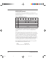
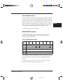
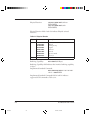
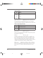
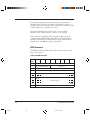
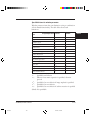
REVISION RECORD
Edition
Date published
01
Feburary, 1996
First edition
Revised contents
02
April, 1996
Setup mode etc. revised
Specification No. C150-E049-02EN
The contents of this manual may be revised without prior notice.
All Rights Reserved, Copyright © 1996 FUJITSU LIMITED.
Printed in Japan.
No part of this manual may be reproduced in any form without permission.
Address your comments and inquiries on this manual to:
FUJITSU COMPUTER PRODUCTS OF
AMERICA, INC.
2904 Orchard Parkway, San Jose.
California 95134-2022, U.S.A.
TEL: 1-408-432-6333
FAX: 1-408-432-3908
FUJITSU FRANCE S.A.
Batiment Aristote, 17 rue Olof palme
94006 Creteil cedex, FRANCE
TEL: 33-14-513-1616
FAX: 33-14-399-0700
FUJITSU AUSTRALIA LIMITED
475 Victoria Avenue Chatswood.
N.S.W 2067, AUSTRALIA
TEL: 61-2-410-4555
FAX: 61-2-411-8603
FUJITSU HONG KONG Limited
Room 2521, Sum Hung Kai Centre
30 Harbour Road Wanchal, Hong Kong
TEL: 852-827-5780
FAX: 852-827-4724
TLX: 62667
FUJITSU CANADA, INC.
2800 Matheson Blvd. East, Mississauga.
Ontario 4X5, CANADA
TEL: 1-905-602-5454
FAX: 1-905-602-5457
FUJITSU ITALIA S.p.A.
Via Melchiorre Gioia, No. 8-20124 Milano, ITALY
TEL: 39-2-63651
FAX: 39-2-6572257
FUJITSU DEUTSCHLAND GmbH.
Frankfurter Ring 211,
8000 Munchen 40, F.R, GERMANY
TEL: 49-89-32378-0
FAX: 49-89-32378-100
FUJITSU ESPANA, S.A
Edificio torre Europa
Paseo de la Castellana 95 Madrid 28046, SPAIN
TEL: 34-1-581-8400
FAX: 34-1-581-8125
FUJITSU NORDIC AB
Kung Hans vag, S-191 76 Sollentuna, SWEDEN
TEL: 46-8-626-6000
FAX: 46-8-626-6711
FUJITSU LIMITED
International Operations
Marunouchi 1-6-1, Chiyoda-ku, Tokyo 100, JAPAN
TEL: (81-3) 3216-3211
FAX: (81-3) 3213-7174
TLX: J22833
Cable: “FUJITSU LIMITED TOKYO”
FUJITSU EUROPE LTD.
2, Longwalk Road, Stockley Park, Uxbridge
Middlesex, UB11 1AB, U.K
TEL: 44-81-573-4444
FAX: 44-81-573-2643
TLX: 263871
M3099GX/GH OEM Manual
#00-2 RevisionRecord.pm5
1
98.2.22, 1:13 PM
Preface
This manual provides technical information required to use the
original equipment manufacturing (OEM) M3099G image scanner.
The manual is organized as shown below.
Chapter 1 Overview
Chapter 1 provides the scanner features, configuration, and
operation.
Chapter 2 Specifications
Chapter 2 provides general, electrical, environmental, physical, and
option specifications.
Chapter 3 Interface Specifications
Chapter 3 provides SCSI interface specifications.
Chapter 4 Basic Operation
Chapter 4 provides power switch operation, opening/closing the
upper transport unit, operator panel arrangement and functions,
messages, loading document, and replacement of parts.
Chapter 5 Error Processing and Recovery
Chapter 5 provides how to handles temporary errors and equipment
errors and what the operator should do to recovery.
M3099GX/GH OEM Manual
#00-3 Preface.pm5
1
i
98.2.22, 1:13 PM
Chapter 6 Document Specification
Chapter 6 provides document specifications (size, type, limitations,
grounding color area, drop-out color, and job separation sheet) for
the scanner.
Chapter 7 Consumables and Accessories
Chapter 7 provides consumables and accessories.
Chapter 8 Cleaning
Chapter 8 provides cleaning locations and frequencies, cleaning
tools, and procedures.
It is recommended that you thoroughly familiarize yourself with the
contents of this manual before attempting to use the scanner.
Operators in particular must have read Chapter 4, “Basic
Operation.”
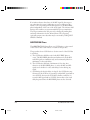
Conventions
Special information, such as warnings, cautions are indicated as
follows:
WARNING
A WARNING indicattes that personal injury may result if you do
not follow a procedure correctly.
CAUTION
A CAUTION indicates that damage to the scanner may result if you
do not follow a procedure correctly.
NOTICE
A NOTICE provides “how-to” tips or suggestions to help you
perform a procedure correctly. NOTEs are particularly useful for
first-time users.
ii
#00-3 Preface.pm5
M3099GX/GH OEM Manual
2
98.2.22, 1:13 PM
Contents
CHAPTER 1
OVERVIEW␣ .................................................................................. 1-1
Scanner Types .............................................................................. 1-1
Features␣ ....................................................................................... 1-4
Configuration ............................................................................... 1-5
Configuration of the scanner .................................................. 1-5
Arrangement of units ............................................................. 1-6
Operation Overview ..................................................................... 1-7
Operation of the mechanism unit .......................................... 1-7
Operation of the control unit ................................................. 1-8
Resolution.............................................................................. 1-9
CHAPTER 2
SPECIFICATIONS␣ ........................................................................ 2-1
General ......................................................................................... 2-1
Electrical Specifications ................................................................ 2-2
Environmental Specifications ....................................................... 2-2
Physical specifications ................................................................... 2-3
Option specifications .................................................................... 2-6
CHAPTER 3
INTERFACE␣ ................................................................................. 3-1
Physical Specifications .................................................................. 3-3
SCSI Bus (See ANSI SCSI-2 4.5) ........................................... 3-7
SCSI Bus Signals (See ANSI SCSI-2 4.6) ............................... 3-8
Signal Values.......................................................................... 3-9
Signal Source ......................................................................... 3-9
SCSI Bus Timing ................................................................. 3-11
Arbitration Delay .......................................................... 3-12
Assertion period............................................................. 3-12
Bus Clear Delay ............................................................. 3-12
Bus Free Delay .............................................................. 3-12
Bus Set Delay ................................................................ 3-12
Bus Settle Delay ............................................................ 3-13
Cable Skew Delay .......................................................... 3-13
M3099GX/GH OEM Manual
#00-4 Contents.pm5
3
iii
98.2.22, 1:14 PM
Data Release Delay ........................................................ 3-13
Deskew Delay................................................................ 3-13
Disconnection Delay ..................................................... 3-13
Hold Time .................................................................... 3-13
Negation Period ............................................................ 3-13
Power-On to Selection Time ......................................... 3-14
Reset to Selection Time ................................................. 3-14
Reset Hold Time ........................................................... 3-14
Selection Abort Time .................................................... 3-14
Selection Time-out Delay .............................................. 3-14
Transfer Period .............................................................. 3-15
SCSI Bus Phases ......................................................................... 3-15
BUS FREE Phase (See ANSI SCSI-2 6.1.1 for details) ......... 3-15
ARBITRATION Phase ........................................................ 3-16
SELECTION Phase ............................................................. 3-17
RESELECTION Phase ........................................................ 3-18
RESELECTION ........................................................... 3-18
Information Transfer Phases ................................................ 3-19
Asynchronous Information Transfer .............................. 3-20
Synchronous Data Transfer ........................................... 3-21
COMMAND Phase ............................................................. 3-22
Data Phase ........................................................................... 3-22
DATA IN Phase ............................................................ 3-23
DATA OUT Phase ....................................................... 3-23
STATUS Phase .................................................................... 3-23
Message Phase ...................................................................... 3-23
MESSAGE IN Phase ..................................................... 3-23
MESSAGE OUT Phase (See ANSI SCSI-2 6.1.9.2 for
details) ........................................................................... 3-24
SCSI Bus Conditions.................................................................. 3-24
Attention Condition ............................................................ 3-24
Reset Condition ................................................................... 3-25
SCSI Bus Phases Sequences ........................................................ 3-26
Commands (See ANSI SCSI-2 7) ............................................... 3-27
RESERVE UNIT Command ............................................... 3-30
Superseding Reservations ............................................... 3-31
RELEASE UNIT Command ............................................... 3-31
TEST UNIT READY Command ........................................ 3-32
INQUIRY Command (See ANSI SCSI-2 7.2.5) .................. 3-32
Standard INQUIRY Data (See ANSI SCSI-2 7.2.5.1) .. 3-34
iv
#00-4 Contents.pm5
M3099GX/GH OEM Manual
4
98.2.22, 1:14 PM
Vital Product Data ........................................................ 3-37
REQUEST SENSE Command (See ANSI SCSI-2 8.2.14) .. 3-49
SEND DIAGNOSTIC Command ...................................... 3-55
SET WINDOW Command ................................................ 3-56
Vendor Unique Parameters ........................................... 3-65
OBJECT POSITION .......................................................... 3-73
SEND Command ................................................................ 3-74
SCAN Command ................................................................ 3-79
READ Command ................................................................ 3-80
MODE SELECT(6) Command .......................................... 3-86
MODE SENSE(6) Command ............................................. 3-87
Mode Parameter ............................................................ 3-88
ENDORSER Command (ENDORSER option is required) 3-92
Status (See ANSI SCSI-2 7.3) ..................................................... 3-97
Message(See ANSI SCSI-2 6.5) .................................................. 3-99
ABORT (Init → Targ) ...................................................... 3-102
BUS DEVICE RESET (Init → Targ) ................................ 3-103
COMMAND COMPLETE (Init ← Targ) ....................... 3-103
DISCONNECT (Init ← Targ) ......................................... 3-103
IDENTIFY (Init → Targ) ................................................. 3-104
INITIATOR DETECTED ERROR (Init → Targ) .......... 3-105
MESSAGE PARITY ERROR (Init → Targ) ..................... 3-105
MESSAGE REJECT (Init ↔ Targ) ................................... 3-106
NO OPERATION (Init → Targ) ..................................... 3-106
RESTORE POINTERS (Init ← Targ) .............................. 3-107
SAVE DATA POINTER (Init ← Targ) ............................ 3-107
SYNCHRONOUS DATA TRANSFER REQUEST ........ 3-107
Command Sequence ................................................................. 3-110
System Initialization ........................................................... 3-110
General Procedure for Initializing Devices ......................... 3-111
Verify State Test ................................................................ 3-112
Scanning Sequence ............................................................. 3-115
Basic Scanning Sequence (Simplex Mode) : ................. 3-115
Duplex Scanning ......................................................... 3-116
Endorser Control......................................................... 3-117
READ command sequences and phase progression ............ 3-118
Multiple READ (disconnect disabled) ......................... 3-119
Multiple READ (disconnect enabled) .......................... 3-120
M3099GX/GH OEM Manual
#00-4 Contents.pm5
5
v
98.2.22, 1:14 PM
CHAPTER 4
BASIC OPERATION␣ ..................................................................... 4-1
Power Switch Operation ............................................................... 4-1
Opening the Upper Transport Unit ............................................. 4-2
Closing the Upper Transport Unit ............................................... 4-2
Operator Panel ............................................................................. 4-3
Operator panel function ......................................................... 4-3
LCD display .......................................................................... 4-5
Buttons .................................................................................. 4-7
Message List ........................................................................... 4-8
Loading Document ...................................................................... 4-9
Lamp Replacement ..................................................................... 4-10
Roller ASY Replacement ............................................................. 4-16
Pick Roller Replacement ............................................................. 4-18
Belt Replacement........................................................................ 4-19
Pad Replacement ........................................................................ 4-21
CHAPTER 5
ERROR PROCESSING AND RECOVERY␣ ....................................... 5-1
Device and Operator Actions for Temporary Errors ..................... 5-1
Device and Operator Actions for Equipment Errors ..................... 5-4
CHAPTER 6
DOCUMENT SPECIFICATION␣ ...................................................... 6-1
Document Size ............................................................................. 6-1
Document Quality ....................................................................... 6-2
Document type ...................................................................... 6-2
Ream weight .......................................................................... 6-2
Precautions ............................................................................ 6-2
Document Limitations ................................................................. 6-4
Areas that must not be perforated .......................................... 6-4
Print prohibit areas on the front and back surfaces ................. 6-5
Grounding Color Area.................................................................. 6-6
Drop-out Color ............................................................................ 6-7
Print density measurement ..................................................... 6-7
Drop-out color standards ....................................................... 6-7
Job Separation Sheet ..................................................................... 6-8
Shape ..................................................................................... 6-8
Document type ...................................................................... 6-8
vi
#00-4 Contents.pm5
M3099GX/GH OEM Manual
6
98.2.22, 1:14 PM
CHAPTER 7
CONSUMABLES AND ACCESSORIES␣ ......................................... 7-1
Consumables ................................................................................ 7-1
Accessories .................................................................................... 7-2
CHAPTER 8
CLEANING␣ ................................................................................... 8-1
Cleaning Locations and Frequencies ............................................. 8-1
Cleaning Tools ............................................................................. 8-2
Procedure ..................................................................................... 8-2
Cleaning the front-side lamp .................................................. 8-2
Cleaning the rollers ................................................................ 8-5
Cleaning the transport paths .................................................. 8-6
Cleaning the glass surface ....................................................... 8-7
Cleaning the sensors ............................................................... 8-7
APPENDIX A
ENDORSER␣ .................................................................................. A-1
A1. Specification .......................................................................... A-1
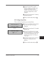
A2. Panel operation ...................................................................... A-2
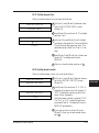
A2.1 How to set the endorser ON (or OFF) ..........................A-2
A2.2 How to set the initial number ........................................A-2
A2.3 How to set the print number reset condition ................. A-3
A2.4 How to reset the print number manually ....................... A-3
A2.5 How to reset the print head life counter ........................A-4
A2.6 How to test the printing by the operator
panel operation ............................................................. A-4
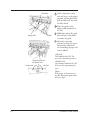
A3. Print head handling ................................................................A-5
A3.1 Replacing the print head ................................................A-5
A3.2 Print head position adjustment ......................................A-6
APPENDIX B
SETUP MODE␣ .............................................................................. B-1
B1. Activating the setup mode ...................................................... B-1
B2. Operational transition in the setup mode ............................... B-1
B3. Contents of the setup mode ................................................... B-2
B3.1 Setting double-feed detection ........................................ B-3
B3.2 Setting IPC-2 pre-set mode ........................................... B-4
B3.3 Reset of abrasion counter ............................................... B-6
B3.4 Setting buzzer ................................................................ B-7
B3.5 Setting pre-pick ............................................................. B-7
M3099GX/GH OEM Manual
#00-4 Contents.pm5
7
vii
98.2.22, 1:14 PM
B3.6 Adjusting LCD contrast ................................................ B-8
B3.7 Setting pick speed .......................................................... B-8
B3.8 Setting initial value of endorser ...................................... B-9
B3.9 Setting reset method of endorser .................................... B-9
B3.10 Reset of endorser ....................................................... B-10
B3.11 Reset of ink counter ................................................... B-10
B3.12 Setting SCSI-ID ........................................................ B-10
B3.13 Setting Product-ID .................................................... B-10
B3.14 Setting picking start time ........................................... B-11
B3.15 Setting picking time................................................... B-12
B3.16 Setting time-out limit ................................................ B-12
B3.17 Setting hopper time ................................................... B-13
B3.18 Setting heater control ................................................ B-13
APPENDIX C
SEPARATION PRESSURE ADJUSTMENT ................................... C-1
GLOSSARY OF TERMS
.................................................................................................. GL-1
INDEX
................................................................................................... IN-1
viii
#00-4 Contents.pm5
M3099GX/GH OEM Manual
8
98.2.22, 1:14 PM
Figures
1.1
1.2
1.3
1.4
1.5
500 sheets hopper type ......................................................... 1-2
1000 sheets hopper type ....................................................... 1-3
Scanner block diagram ......................................................... 1-5
Arrangement of units ............................................................ 1-6
Control block diagram ......................................................... 1-8
2.1 Dimensions of 500 sheets hopper type ................................. 2-3
2.2 Dimensions of 1000 sheets hopper type ............................... 2-4
2.3 Service areas ......................................................................... 2-5
3.1
3.2
3.3
3.4
3.5
3.6
SCSI device connection ........................................................ 3-3
Alternative 1 termination for Single Ended Devices .............. 3-5
Alternative 2 termination for Single Ended Devices .............. 3-5
DATA BUS.......................................................................... 3-7
Phase Sequence................................................................... 3-26
Verify State Test ............................................................... 3-113
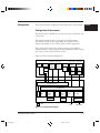
4.1 Power switch location ........................................................... 4-1
4.2 Operator panel layout ........................................................... 4-3
6.1
6.2
6.3
6.4
6.5
6.6
Document size...................................................................... 6-1
Areas that must not be perforated ......................................... 6-4
Print prohibit areas on the front and back surfaces ............... 6-5
Grounding color area ........................................................... 6-6
Spectrum band ..................................................................... 6-7
Shape of document ............................................................... 6-8
A.1 Print area .............................................................................. A-1
M3099GX/GH OEM Manual
#00-4 Contents.pm5
9
ix
98.2.22, 1:14 PM
Tables
1.1 Types of M3099GH ............................................................ 1-1
1.2 Types of M3099GX ............................................................. 1-2
2.1
2.2
2.3
2.4
2.5
General scanner specifications .............................................. 2-1
Electrical specifications ......................................................... 2-2
Environmental specifications ................................................ 2-2
Physical specifications ........................................................... 2-5
Option specifications ............................................................ 2-6
3.1 SCSI physical specification ................................................... 3-4
3.2 Single Ended Contact Assignment - ‘A’ Cable ...................... 3-6
3.3 SCSI Bus Signals .................................................................. 3-8
3.4 Signal Source ...................................................................... 3-10
3.5 SCSI Bus Timing Values .................................................... 3-11
3.6 Information Transfer Phases ............................................... 3-20
3.7 Operation Code Types ....................................................... 3-29
3.8 RESERVE UNIT Command ............................................. 3-30
3.9 RELEASE UNIT Command .............................................. 3-31
3.10 TEST UNIT READY Command ...................................... 3-32
3.11 INQUIRY Command ........................................................ 3-33
3.12 Standard INQUIRY Data Format ...................................... 3-35
3.13 Standard VPD Page Format ............................................... 3-38
3.14 Standard Resolution (unit:Pixel/Inch) ................................ 3-39
3.15 Function ............................................................................ 3-40
3.16 Standard VPD Page Extended Format ................................ 3-41
3.17 Physical Function ............................................................... 3-42
3.18 Implemented Standard Command ..................................... 3-43
3.19 2 bytes structure ................................................................. 3-44
3.20 Implemented Vendor Specific Command .......................... 3-44
3.21 Implemented Vendor Specific Command .......................... 3-44
3.22 Vendor Unique Parameter .................................................. 3-45
3.23 Image Control Function ..................................................... 3-47
3.24 Image Processing Function ................................................. 3-47
3.25 Compression Function ....................................................... 3-48
3.26 Endorser Function .............................................................. 3-48
3.27 REQUEST SENSE Command .......................................... 3-49
3.28 Sense Data Format ............................................................. 3-50
x
#00-4 Contents.pm5
M3099GX/GH OEM Manual
10
98.2.22, 1:14 PM
3.29 Sense Key Descriptions ....................................................... 3-52
3.30 Implementation of SK(Sense Key), ASC(Additional Sense
Code), ASCQ(Additional Sense Code Qualifier) Hierachy. 3-54
3.31 SEND DIAGNOSTIC Command .................................... 3-55
3.32 SET WINDOW Command............................................... 3-56
3.33 Set Window Data Header .................................................. 3-57
3.34 Window descriptor Bytes ................................................... 3-58
3.35 Brightness ........................................................................... 3-61
3.36 Threshold ........................................................................... 3-61
3.37 Contrast ............................................................................. 3-62
3.38 Image Composition Codes ................................................. 3-62
3.39 Halftone Type .................................................................... 3-63
3.40 Halftone Pattern ................................................................. 3-63
3.41 Compression Types and Arguments ................................... 3-64
3.42 Image Processing Parameter ............................................... 3-65
3.43 Gamma Correction Table .................................................. 3-66
3.44 Outline Extract .................................................................. 3-66
3.45 Image Emphasis ................................................................. 3-67
3.46 Automatic Separation ......................................................... 3-67
3.47 Mirroring ........................................................................... 3-67
3.48 SDTC parameter ................................................................ 3-68
3.49 DTC Mode - Byte 47 ......................................................... 3-69
3.50 DTC Mode - Byte 48 ......................................................... 3-69
3.51 White Level Follower ......................................................... 3-70
3.52 Paper Size ........................................................................... 3-71
3.53 DTC Selection ................................................................... 3-72
3.54 OBJECT POSITION Command ...................................... 3-73
3.55 Position Function ............................................................... 3-73
3.56 SEND Command .............................................................. 3-74
3.57 Halftone Mask ................................................................... 3-76
3.58 Gamma Function Data Format .......................................... 3-78
3.59 SCAN Command ............................................................... 3-79
3.60 READ Command .............................................................. 3-80
3.61 Data Type Codes ............................................................... 3-81
3.62 Pixel Size Data.................................................................... 3-83
3.63 Detected Paper Information ............................................... 3-84
3.64 Job Separation Sheet........................................................... 3-84
3.65 Paper Size ........................................................................... 3-85
3.66 MODE SELECT(6) Command ......................................... 3-86
3.67 MODE SENSE(6) Command ........................................... 3-87
M3099GX/GH OEM Manual
#00-4 Contents.pm5
11
xi
98.2.22, 1:14 PM
3.68 Supported Mode Page Code ............................................... 3-88
3.69 Mode Parameter List .......................................................... 3-88
3.70 Mode Parameter Header(6) ................................................ 3-89
3.71 Mode Page Format ............................................................. 3-89
3.72 Lamp Timer page ............................................................... 3-90
3.73 Job Separation Sheet page................................................... 3-91
3.74 Job Separation Sheet Parameter .......................................... 3-91
3.75 ENDORSER Command .................................................... 3-92
3.76 Endorser Descriptors .......................................................... 3-93
3.77 Endorser Data .................................................................... 3-94
3.78 Font ................................................................................... 3-95
3.79 DIRS .................................................................................. 3-96
3.80 Status Byte ......................................................................... 3-97
3.81 Status Byte Code ................................................................ 3-97
3.82 Message Format ................................................................. 3-99
3.83 Message Codes ................................................................. 3-100
3.84 Extended Message Format ................................................ 3-101
3.85 Extended Message Codes .................................................. 3-101
3.86 IDENTIFY message ......................................................... 3-104
3.87 SYNCHRONOUS DATA TRANSFER REQUEST ....... 3-107
4.1 Button functions .................................................................. 4-4
4.2 LEDs function...................................................................... 4-4
4.3 Messages ............................................................................... 4-8
5.1 Device and operator actions for temporary errors ................. 5-1
5.2 Device and operator actions for equipment errors ................. 5-4
7.1 Consumables ........................................................................ 7-1
7.2 Accessories ............................................................................ 7-2
8.1 Cleaning locations and frequencies ....................................... 8-1
A.1 Endorser specifications ......................................................... A-1
xii
#00-4 Contents.pm5
M3099GX/GH OEM Manual
12
98.2.22, 1:14 PM
Chapter 1: Overview
OVERVIEW
Chapter 2: Specifications
SPECIFICATIONS
Chapter 3: Interface
INTERFACE
Chapter 4: Basic Operation
BASIC
OPERATION
Chapter 5: Error Processing and Recovery
ERROR
PROCESSING
AND RECOVERY
Chapter 6: Document Specification
DOCUMENT
SPECIFICATION
Chapter 7: Consumables and Accessories
CONSUMABLES
AND
ACCESSORIES
Chapter 8: Cleaning
CLEANING
Appendix A:Endorser
ENDORSER
Appendix B:Setup Mode
SETUP MODE
Appendix C:Separation Pressure Adjustment
SEPARATION
PRESSURE
ADJUSTMENT
Glossary of Terms
GLOSSARY OF
TERMS
Index
INDEX
6
#00-5 TagReference.pm5
1
98.2.22, 1:19 PM
CHAPTER
1
OVERVIEW
OVERVIEW
This chapter provides scanner features, configuration, and operation.
Scanner Types
The M3099GX/GH is a very fast and highly functional image
scanner developed for volume filing, using charge-coupled device
(CCD) image sensors. This scanner, featuring duplex reading and
high-quality image processing, read documents fed by an automatic
document feeder (ADF).
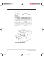
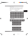
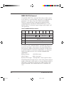
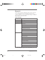
Scanner types of M3099GH and M3099GX are shown in Table 1.1
and 1.2. Those types of the scanner is hereinafter referred to as “this
scanner”.
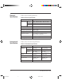
Table 1.1 Types of M3099GH
Type
Item
Maximum
document size
Scanning Simplex
Duplex
Hopper capacity
Hight of
the Scanner
IPC2 (option)
Input voltage
Appearance
500 sheets hopper
with IPC2
100V
200V
1000 sheets hopper
with IPC2
100V
200V
A4/Letter/Legal
80 PPM (A4, 200dpi, portate)
60 PPM (A4, 200dpi, portrate)
500 sheets
1000 sheets
470 mm
530 mm
Installed
100V
200V
Figure 1.1
Installed
100V
200V
Figure 1.2
M3099GX/GH OEM Manual
#01 Chapter 1
1
1-1
98.2.22, 1:21 PM
Table 1.2 Types of M3099GX
Type
Item
Maximum
document size
Scanning Simplex
Duplex
Hopper capacity
Hight of
the Scanner
IPC2 (option)
Input voltage
Appearance
1000 sheets hopper
with IPC2
100V
200V
A3/Double letter
60 PPM (A4, 200dpi, portate)
50 PPM (A4, 200dpi, portrate)
1000 sheets
530 mm
Installed
100V
200V
Figure 1.2
Figure 1.1 500 sheets hopper type
1-2
#01 Chapter 1
M3099GX/GH OEM Manual
2
98.2.22, 1:21 PM
OVERVIEW
Figure 1.2 1000 sheets hopper type
M3099GX/GH OEM Manual
#01 Chapter 1
3
1-3
98.2.22, 1:21 PM
Features
This scanner has the following features:
Duplex reading
Both sides of a document are read at the same time and their data
transferred serially.
Fast reading
This scanner can read documents at high speed: 80 sheets/min (A4,
200dpi) in the simplex reading mode and 60 sheets/min (A4,
200dpi) in the duplex reading mode by M3099GH.
Large-capacity hopper
Up to 1000 sheets (A4, 55 kg) can be loaded on the hopper by the
1000 sheets hopper type.
High-quality image
This scanner uses a compact optical system that provides sharper
focus. Furthermore, the use of new LSI chips produces finer images.
New image processing function
The error diffusion feature is provided as standard. Dithering or
error diffusion can be applied to those areas judged to be
photographs by automatic separation (image processing II option).
1-4
#01 Chapter 1
M3099GX/GH OEM Manual
4
98.2.22, 1:21 PM
Configuration
This section provides configuration and components of the scanner.
Configuration of the scanner
This scanner can be divided into two major sections, mechanism and
control unit.
The mechanism unit consists of a hopper to load documents,
automatic document feeder, upper and lower transport units to
transport documents, a motor drive system, and an optical unit.
The control unit consists of an operator panel, a power supply, a
mechanism driver to drive and control the mechanism unit, an image
processing control, and an interface control.
Figure 1.3 shows scanner configuration.
Mechanism unit
Transfer
system
(Front-side) (Back-side)
Sensor
Lamp,
heater,
inverter
Lamp,
heater,
inverter
Sensor
board
Printer
Printer
driver
(Front-side)
(Back-side)
Optical
system
Optical
system
CCD
driver
Video
circuit
CCD
driver
Video
circuit
Control unit
Mechanism driver
Motherboard
Fan
Operator
panel
Back-side
reading
board
IPC-2
Extend
memory
board
Interface
board
(Front-side)
IPC-2
(Back-side)
: Option
Power supply
(5V, 12V)
Power supply
(24V)
Extend
memory
SCSI-2
100/200VAC
Figure 1.3 Scanner block diagram
M3099GX/GH OEM Manual
#01 Chapter 1
5
1-5
98.2.22, 1:21 PM
OVERVIEW
Arrangement of units
Figure 1.4 shows arrangement of these units.
Power supply units
(+24V)
+5V
±12V
Operator panel
Control unit
Stacker
Optical unit
(front-side)
Automatic document
feeder (ADF)
Power inlet
Hopper
Optical unit
(back-side)
Power switch
Figure 1.4 Arrangement of units
1-6
#01 Chapter 1
M3099GX/GH OEM Manual
6
98.2.22, 1:21 PM
Operation
Overview
This section outlines the operations of the mechanism and control
units of the scanner.
OVERVIEW
Operation of the mechanism unit
The mechanism unit consists of two optical units (front and back
sides), a hopper and ADF, upper and lower transport units, a motor
drive system, and a stacker. Each optical unit consists of a CCD
image sensor, a lens, and mirrors. The hopper and ADF feeds
stacked documents and the upper and lower transport units transport
the documents. The motor drive system drives these units. The
stacker stores documents.
When the power is turned on, the lamps are lit and the scanner
waits until the light intensities of the lamps become stable. Once the
light intensities have become stable, the scanner is ready for a
command from the host machine.
A document is picked from the hopper and then ADF feeds a
document one by one. The document width is checked and
document top is detected.
The documents are counted, fed, and stacked on the stacker.
The lamps illuminate the document, and a lens focuses the images
on CCD for photoelectric conversion processing.
M3099GX/GH OEM Manual
#01 Chapter 1
7
1-7
98.2.22, 1:22 PM
Operation of the control unit
The control unit consists of an operator panel, a power supply unit,
mechanism driver, an image processing control, and an interface
control.
This scanner has the following circuit configuration:
• Operator panel
• Control circuit (MPU)
• Video circuit (front-side/back-side)
• Interface circuit
• Duplex circuit (back-side)
• Motor driver circuit (including a stepper motor, a clutch driver)
• Power supply unit
• Image processing circuit (IPC II option)
• Memory board
Figure 1.5 shows control block diagram.
Host
machine
Interface
circuit
Control
circuit
(MPU )
Power
supply
Video
circuit
(front-side)
Mechanism
unit
Video
circuit
(back-side)
ADF
MF
Image
processing
circuit II
(option)
(front-side)
Duplex
circuit
Image
processing
circuit II
(option)
(back-side)
Memory
board
100 to 120 VAC
220 to 240 VAC
Power
switch
Motor
driver
circuit
Operator
panel
Figure 1.5 Control block diagram
1-8
#01 Chapter 1
M3099GX/GH OEM Manual
8
98.2.22, 1:22 PM
Main control unit
OVERVIEW
This scanner is controlled by a 80C186 MPU. This scanner consists
of a ROM as a program area, internal registers, an external RAM as a
work area, gate arrays for the MPU peripheral and video circuits,
dither processing and γ conversion RAMs, and error diffusion.
Interface control
SCSI-2 interface
SCSI (small computer system interface) circuit consists of SPC
(MB86601A), VCEP (OTI95C71/20) and a glue ASIC. The scanned
image data are transferred to interface circuit as video interface. The
interface circuit converts internal video interface to SCSI interface via
compression, if required. SCSI interface transferes data 1.5MB/s in
Asynchronous transfer, 4.0MB/s in Synchronous transfer following to
SCSI-2 standard. The VCEP compresses the binary image data in
MH, MR, MMR algorithm defined by CCITT G3, G4. See Chapter
3 for details of SCSI interface.
Resolution
The basic resolution of this scanner is 200dpi. The resolution can be
changed to 240, 300, or 400dpi from the host computer or the
operator panel.
The resolution in the subscanning direction is achieved by changing
the document transport speed.
When the image processing circuit II (IPC II) option is installed, the
linear density is changed by setting the parameter to its internal circuit.
Video amplifier and driver section
This section consists of a CCD drive circuit, a video amplifier circuit,
a white-black level correction circuit, sensors, and also control circuits
for the stepping motor, heater, and lamps.
M3099GX/GH OEM Manual
#01 Chapter 1
9
1-9
98.2.22, 1:22 PM
Image processing section
The IPC II option enables the following image processing functions:
• Automatic separation function (to read documents containing
characters and photographs)
• Inversion function
• Mirror image output function
• Outline extraction function
• Overlay function
• Smoothing, filtering, and noise removing
Power supplies
This scanner has two power supplies. Their output voltages are as
follows:
Power supply 1
• +5V: For logic circuits
• ±12V: For video amplifiers
Power supply 2
• 24V: For lamp, heater, and stepping motor drive
1-10
#01 Chapter 1
M3099GX/GH OEM Manual
10
98.2.22, 1:22 PM
CHAPTER
2
SPECIFICATIONS
SPECIFICATIONS
This chapter provides general, electrical, environmental, physical,
and option specifications.
Table 2.1 list general scanner specifications.
General
Table 2.1 General scanner specifications
Type
Item
Sensor
Scanning method
MAX.
Document
size
MIN.
Light source
Hopper/stacker
capacity (64 g/m2 )
Gray scale (internal)
Output video
Scanning speed (A4, Simplex
200dpi, portrait)
Duplex
Output density
Binarization and
halftone function
Interface
M3099GH
M3099GX
500 sheets hopper 1000 sheets hopper 1000 sheets hopper
CCD image sensor
ADF (automatic document feeder) & MF (manual feeder)
216 × 356 mm (A4/Letter/Legal) 297 × 432 mm (A3/Double letter)
76 × 63 mm (3" × 2.5")
Green fluorescent lamp
MAX. 500 MAX. 1000
MAX. 1000
sheets
sheets
sheets
256 steps
Binary/Halftone (64 levels)
80 PPM
60 PPM
60 PPM
50 PPM
Standard: 400, 300, 240, 200dpi (Horizontal
scanning and vertical scanning are independent.)
If the image processing II (IPC2) is installed: 50 to
400 dpi (Horizontal scanning and vertical scanning
are independent.)
Standard: Fixed binarization, dither, error diffusion
method. If the image processing II (IPC2) is
installed: Automatic separation, image emphasis,
outline extraction, mirror image, inversion,
simplified DTC. Dynamic threshold, smoothing,
filtering, nois removing.
SCSI-2
M3099GX/GH OEM Manual
#02 Chapter 2
1
2-1
98.2.22, 1:30 PM
Electrical
Specifications
Table 2.2 lists electrical specifications.
Table 2.2 Electrical specifications
Item
Specification
Input power
Environmental
Specifications
Voltage
100 to 120 VAC/220 to 240 VAC ±10%
Phase
Single-phase
Frequency
50/60 Hz +2%, –4%
Power consumption
0.25 kVA or less
Rush current
30 A or less
Momentary power failure
100%, 0.5 Hz
Leakage current
3.5 mA or less
Dielectric strength
DC 1.8 KV for one minute or more
(between FG and AC lines)
AC line noise
Voltage 1.2 KV pulse duration 5 µs
Heat capacity
110 Kcal/H (440 BTU/H)
Table 2.3 lists environmental specifications.
Table 2.3 Environmental specifications
Item
Specification
Ambient Device status
conditions Temperature
Operating
Not operating
5 to 35°C
–20 to 60°C
20 to 80%
(no condensation)
8 to 95%
(no condensation)
Shock
0.2 G less
0.4 G or less
Stability
5° or less
10° or less
Acoustic noise
59 dBA or less
(ISO 7779)
50 dBA or less
(ISO 7779)
ESD
8 KV or more
Humidity
2-2
#02 Chapter 2
M3099GX/GH OEM Manual
2
98.2.22, 1:30 PM
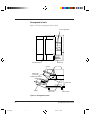
Physical
Specifications
Figure 2.1 to Figure 2.2 show the scanner dimensions, Figure 2.3
shows scanner service areas. Table 2.4 lists physical specifications.
610
SPECIFICATIONS
470
680
(Unit: mm)
Figure 2.1 Dimensions of 500 sheets hopper type
M3099GX/GH OEM Manual
#02 Chapter 2
3
2-3
98.2.22, 1:30 PM
610
530
680
(Unit: mm)
Figure 2.2 Dimensions of 1000 sheets hopper type
2-4
#02 Chapter 2
M3099GX/GH OEM Manual
4
98.2.22, 1:30 PM
Table 2.4 Physical specifications
Type
Item
Dimensions
500 sheets hopper type
1000 sheets hopper type
610 mm
680 mm
470 mm
55kg
610 mm
680 mm
530 mm
65kg
Width
Depth
Height
Scanner
1,860
680
600
Weight
600
F
200
610
600
1,390
F: Front
(Unit: mm)
Figure 2.3 Service areas
M3099GX/GH OEM Manual
#02 Chapter 2
5
2-5
98.2.22, 1:30 PM
SPECIFICATIONS
Option
Specifications
Table 2.5 lists the scanner option specifications.
Table 2.5 Option specifications
Item
Specification
Endorser CA01023-D004
2-6
#02 Chapter 2
Detail
Remark
Ink-jet
back-side print
max. 20 characters
M3099GX/GH OEM Manual
6
98.2.22, 1:30 PM
CHAPTER
3
INTERFACE
The M3099G image scanner provides SCSI-2(Small Computer
System Interface-2) interface. The SCSI-2 is a 8 bit-parallel interface
standardized by ANSI(American National Standard Institute).
This chapter provides an overview of the SCSI and interface
specification of this scanner. For detail information, refer to ANSI
SCSI standard document.
Definitions
• SCSI device: A host adapter or a target controller that can be
attached to the SCSI bus.
• Initiator:
An SCSI device that requests an I/O process to be
performed by another SCSI device(a target).
• Target:
An SCSI device that performes an operation
requested by an initiator.
• Logical unit: A physical or virtual peripheral device addressable
through a target.
Scope
This interface specification is following X3T9.2 draft proposal
revision 10c. refering JBMS(Japan Business Machine Standard).
System configuration
This scanner operates under the multi-initiator, multi-target
environment. An initiator function is not provided. This scanner
incorporates an integrated target and logical unit (image scanner).
SCSI ID:
0 to 7(changeable), default 5.
Logical Unit Number (LUN): 000b(fixed).
M3099GX/GH OEM Manual
#03.pm5
1
3-1
98.2.22, 1:31 PM
INTERFACE
Bus phases
All phases are supported
Commands
• INQUIRY
• OBJECT POSITION
• MODE SELECT(6)
• MODE SENSE(6)
• READ
• RELEASE UNIT
• REQUEST SENSE
• RESERVE UNIT
• SCAN
• SEND
• SEND DIAGNOSTIC
• SET WINDOW
• TEST UNIT READY
• ENDORSER (ENDORSER option is required)
Statuses
• BUSY
• CHECK CONDITION
• GOOD
• RESERVEATION CONFLICT
Messages
• ABORT
• BUS DEVICE RESET
• COMMAND COMPLETE
• DISCONNECT
• IDENTIFY
• INITIATOR DETECTED ERROR
• MESSAGE PARITY ERROR
• MESSAGE REJECT
3-2
#03.pm5
M3099GX/GH OEM Manual
2
98.2.22, 1:31 PM
•
•
•
•
Physical
Specifications
NO OPERATION
RESTORE POINTERS
SAVE DATA POINTER
SYNCHRONOUS DATA TRANSFER REQUEST
Connection
INTERFACE
SCSI devices are daisy-chaned together using a common 50conductor ‘A’ cable and, optionally, a 68-conductor ‘B’ cable. Both
ends of each cable are terminated. All signals are common between
all SCSI devices on the ‘A’ cable. In systems that employ the wide
SCSI option, wide SCSI devices additionally connect to the ‘B’ cable.
Various width SCSI devices may be mixed. This scanner supports ‘A’
cable.
Note: Use of ‘B’ cable is not recommended because of ANSI draft
proposal indicates this definition is removed in a future
version of the SCSI.
SCSI device
SCSI device
SCSI device
TERMINATOR
SCSI device
TERMINATOR
Figure 3.1 SCSI device connection
M3099GX/GH OEM Manual
#03.pm5
3
3-3
98.2.22, 1:31 PM
Physical specification
Table 3.1 SCSI physical specification
Item
Specification
Driver/receiver
Single Ended
Connector
50 Contact Shielded Low Density
Cable
Max. cable length
6m
Characteristic impedance
90␣ Ω to 140 Ω
Cable type
25 signal twisted pair
Stub length
≤ 0.1 m (from mainline)
Signal Terminator
level
Driver/receiver
Output characteristics:
Low-level output voltage
High-level output voltage
Input characteristics :
Low level input voltage
High level input voltage
Low level input current
High level input current
Minimum input hysteresis
Connector pin assignments for
signal lines
3-4
#03.pm5
See Figure. 3.2
Open collector or three states driver
0.0 to 0.5 volts dc at 48mA sinking
(signal assertion)
2.5 to 5.25 volts dc (signal
negation)
0.0 to 0.8 volts dc
2.0 to 5.25 volts dc
–0.4 to 0.0mA at Vi=0.5 volts dc
0.0 to 0.1mA at Vi=2.7 volts dc
0.2 volts dc
See Table 3.2
M3099GX/GH OEM Manual
4
98.2.22, 1:31 PM
Termination
All signals not defined as RESERVED, GROUND, or TERMPWR
shall be terminated at both ends of the cable. The Implementor may
choose one of the following two methods to terminate each end (see
ANSI SCSI-2 ANSI SCSI-2 5.4 Electrical description):
INTERFACE
Single-ended alternative (a) [Passive terminator]
TERMINATOR POWER
220 Ω
–SIGNAL
330 Ω
GROUND
Figure 3.2 Alternative 1 termination for Single Ended Devices
Single-ended alternative (b) [Active terminator]
R3
Vin
+
Low dropout voltage regulater
Vout
Imax ≥ 600mA
Vout = 2.85V
(See Note 1)
R1
+
C2
C3
Vadj
Component
R1
R2
R3-R20
C1
C2
C3
Description
121 Ω, 1%, 0.25W
154 Ω, 1%, 0.25W
110 Ω, 1%
10 µF Alum.15V or 4.7 µF Tant. 15V
150 µF Alum.10V or 22 µF Tant. 10V (ESR at 120 Hz < 4)
0.1 µF Ceramic 25V
R2
R20
NOTES
1 The voltage regulator shown is an adjustable type with Vref=1.25V.
R1 and R2 were selected to provide approximately 10mA Iquiescent.
The voltage regulator Vdropout shall be 1.25V or less at Imax.
2 Alternative values that provide lower performance at somewhat
lower cost use Vout 1%; R3−R20=100 Ω,2%
Figure 3.3 Alternative 2 termination for Single Ended Devices
The first termination method above is the same as in SCSI-1. The
second termination method is recommended for better signal quality.
M3099GX/GH OEM Manual
#03.pm5
5
3-5
98.2.22, 1:31 PM
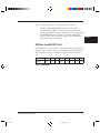
Connector pin assignments
Table 3.2 Single Ended Contact Assignment - ‘A’ Cable
Signal
Name
3-6
#03.pm5
Connector
Cable
Contact
Connector
Number Set 2 Number
Connector
Signal Name
Contact
Number Set 2
GROUND
1
1
2
26
-DB(0)
GROUND
2
3
4
27
-DB(1)
GROUND
3
5
6
28
-DB(2)
GROUND
4
7
8
29
-DB(3)
GROUND
5
9
10
30
-DB(4)
GROUND
6
11
12
31
-DB(5)
GROUND
7
13
14
32
-DB(6)
GROUND
8
15
16
33
-DB(7)
GROUND
9
17
18
34
-DB(P)
GROUND
10
19
20
35
GROUND
GROUND
11
21
22
36
GROUND
GROUND
12
23
24
37
RESERVED
OPEN
13
25
26
38
TERMPWR
GROUND
14
27
28
39
RESERVED
GROUND
15
29
30
40
GROUND
GROUND
16
31
32
41
-ATN
GROUND
17
33
34
42
GROUND
GROUND
18
35
36
43
-BSY
GROUND
19
37
38
44
-ACK
GROUND
20
39
40
45
-RST
GROUND
21
41
42
46
-MSG
GROUND
22
43
44
47
-SEL
GROUND
23
45
46
48
-C/D
GROUND
24
47
48
49
-REQ
GROUND
25
49
50
50
-I/O
M3099GX/GH OEM Manual
6
98.2.22, 1:31 PM
Note: The minus sign next to a signal indicates active low.
The lines labeled RESERVED in the ‘A’ cable contact
assignment tables shall be connected to ground in the bus
terminator assemblies or in the end devices on the SCSI cable.
The RESERVED lines should be open in the other SCSI
devices, but may be connected to ground. The RESERVED
lines in this scanner are opened.
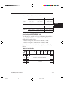
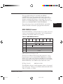
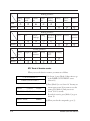
SCSI Bus (See ANSI SCSI-2 4.5)
Communication on the SCSI bus is allowed between only two SCSI
devices at any given time. There is a maximum of eight SCSI devices.
Each SCSI device has an SCSI ID bit assigned as shown in Figure
3.4.
DB(7) DB(6) DB(5) DB(4) DB(3) DB(2) DB(1) DB(0)
SCSI ID
ID=7 ID=6 ID=5 ID=4 ID=3 ID=2 ID=1 ID=0
Figure 3.4 DATA BUS
M3099GX/GH OEM Manual
#03.pm5
7
3-7
98.2.22, 1:31 PM
INTERFACE
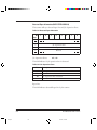
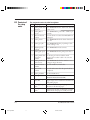
SCSI Bus Signals (See ANSI SCSI-2 4.6)
Table 3.3 SCSI Bus Signals
Signal
Description
BSY(BUSY)
An "OR tied" signal that indicates that the bus is
being used.
SEL(SELECT)
An "OR tied" signal used by an initiator to select
a target or by a target to reselect an initiator.
C/D
A signal driven by a target that controls the
(CONTROL/DATA) direction of data movement on the DATA BUS
with respect to an initiator. True indicates input
to the initiator. This signal is also used to
distiguish between SELECTION and
RESELECTION phase.
MSG(MESSAGE)
A signal driven by a target during the MESSAGE
phase.
REQ(REQUEST)
A signal driven by a target on the A cable to
indicate a request for an ACK information
transfer handshake.
ACK
(ACKNOWLEDGE)
A signal driven by an initiator on the A cable to
indicate an acknowledgement for a REQ
information transfer handshake.
ATN(ATTENTION) A signal driven by an initiator to indicate the
ATTENTION condition.
3-8
#03.pm5
RST(RESET)
An "OR tied" signal that indicates the RESET
condition.
DB(7-0,P)
(DATA BUS)
Eight data bit signals, plus a parity bit signal that
from a DATA BUS. DB(7) is most significant bit
and has the highest priority during the
ATTENTION phase. Bit number, significance
and priority decrese downward to DB(0). A data
bit is defined as one when the signal value is true
and is defined as zero when the signal value is
false. Data parity DB(P) shall be odd. Parity is
undefined during the ARBITRATION phase.
M3099GX/GH OEM Manual
8
98.2.22, 1:31 PM
Signal Values
Signals may assure true or false values. These are two methods of
driving these signals. In both cases, the signal shall be actively driven
true, or asserted. In the case of OR tied drivers, the driver does not
drive the signal to the false state, rather the bias circuitry of the bus
terminators pulls the signal false whenever it is released by the drivers
at every SCSI device. If any driver is asserted, then the signal is true.
In the case of non OR tied drivers, the signal may be actively driven
false. In this standard, whenever the term negated is used, it means
that the signal may be actively driven false, or may be simply released
(in which case the bias circuitry pulls it false), at the option of the
implementor.
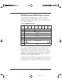
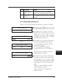
Signal Source
Table 3.4. indicates which type of SCSI device is allowed to source
each signal. No attempt is made to show if the source is driving
asserted driving negated, or is passive. All SCSI device drivers that are
not active sources be in the passive state. The RST signal may be
asserted by any SCSI device at any time.
M3099GX/GH OEM Manual
#03.pm5
9
3-9
98.2.22, 1:31 PM
INTERFACE
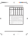
Table 3.4 Signal Source
Bus Phase
BSY
SEL
C/D, I/O,
MSG,
ACK,
REQ
ATN
BUS FREE
ARBITRATION
SELECTION
RESELCTION
COMMAND
DATA IN
DATA OUT
STATUS
MESSAGE IN
MESSAGE OUT
None
All
I&T
I&T
Targ
Targ
Targ
Targ
Targ
Targ
None
Win
Init
Targ
None
None
None
None
None
None
None
None
None
Targ
Targ
Targ
Targ
Targ
Targ
Targ
All:
S ID:
Init:
None:
Win:
Targ:
3-10
#03.pm5
None
None
Init
Init
Init
Init
Init
Init
Init
Init
DB(7,0)
DB(P)
None
S ID
Init
Targ
Init
Targ
Init
Targ
Targ
Init
The signal shall be driven by all SCSI devices that are actively
arbitrating.
A unique data bit (the SCSI ID) shall be driven by each SCSI
device that is actively arbitrating; the other seven data bits shall be
released (i.e., not driven) by this SCSI device. The parity bit
(DB(P)) may be released or driven to the true state, but shall never
be driven to the false state during this phase.
The signal shall be driven by the initiator, target or both, as
specified in the SELECTION phase and RESELECTION phase.
If driven, this signal shall be driven only by the active initiator.
The signal shall be released; that is, not be driven by any SCSI
device. The bias circuitry of the bus terminators pulls the signal to
the false state.
The signal shall be driven by the one SCSI device that wins
arbitration.
If the signal is driven, it shall be driven only by the active target.
M3099GX/GH OEM Manual
10
98.2.22, 1:31 PM
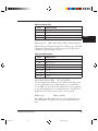
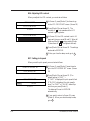
SCSI Bus Timing
Unless otherwise indicated, the delay time measurements for each
SCSI device, shown in Table 3.5., shall be calculated from signal
conditions existing at that SCSI device’s own SCSI bus connection.
Thus, these measurements (except cable skew delay) can be made
without considering delays in the cable. The timing characteristics of
each signal are described in the following paragraphs.
Table 3.5 SCSI Bus Timing Values
Timing Description
Timing Values
Arbitration Delay
2.4 µs
Assertion Period
90 ns
Bus Clear Delay
800 ns
Bus Free Delay
800 ns
Bus Set Delay
1.8 µs
Bus Settle Delay
400 ns
Cable Skew Delay
10 ns
Data Release Delay
400 ns
Deskew Delay
45 ns
Disconnection Delay
200 µs
Hold Time
45 ns
Negation Period
90 ns
Power-On to Selection Time
10 s recommended
Reset to Selection Time
25 µs
Reset Hold Time
200 µs
Selection Abort Time
200 µs
Selection Time-out Delay
250 ms recommended
Transfer Period
set during an SDTR message
M3099GX/GH OEM Manual
#03.pm5
11
3-11
98.2.22, 1:31 PM
INTERFACE
Arbitration Delay
The minimum time an SCSI device shall wait from asserting BSY for
arbitration until the DATA BUS can be examined to see if
arbitration has been won. There is no maximum time.
Assertion period
The minimum time that a target shall assert REQ (or REQB) while
using synchronous data transfers. Also, the minimum time that an
initiator shall assert ACK (or ACKB) while using synchronous data
transfers. REQB and ACKB timings only apply to optional wide data
transfers.
Bus Clear Delay
The maximum time for an SCSI device to stop driving all bus signals
after:
• The BUS FREE phase is detected.
• SEL is received from another SCSI device during the
ARBITRATION phase.
• The transition of RST to true.
For the first condition above, the maximum time for an SCSI device
to clear the bus is 1200 nanoseconds from BSY and SEL first
becoming both false. If an SCSI device requires more than a bus
settle delay to detect BUS FREE phase, it shall clear the bus within a
bus clear delay minus the excess time.
Bus Free Delay
The minimum time that an SCSI device shall wait from its detection
of the BUS FREE phase until its assertion of BSY when going to the
ARBITRATION phase.
Bus Set Delay
The maximum time for an SCSI device to assert BSY and its SCSI
ID bit the DATA BUS after it detects BUS FREE phase for the
purpose of entering the ARBITRATION phase.
3-12
#03.pm5
M3099GX/GH OEM Manual
12
98.2.22, 1:31 PM
Bus Settle Delay
The minimum time for wait for the bus to settle after changing
certain control signals as called out in the protocol definitions.
Cable Skew Delay
INTERFACE
The maximum difference in propergation time allowed between any
two SCSI bus signals measured between any two SCSI devices.
Data Release Delay
The maximum time for an initiator to release the DATA BUS signals
following the transition of the I/O signals from false to true.
Deskew Delay
The minimum time required for deskew of certain signals.
Disconnection Delay
The minimum time that a target shall wait after releasing BSY before
participating in an ARBITRATION phase when honoring a
DISCONNECT message from the initiator.
Hold Time
The minimum time added between the assertion of REQ(or REQB)
or ACK(or ACKB) and the changing of the data lines to provide
hold time in the initiator or target while using synchronous data
transfers. REQB and ACKB timings only apply to optional wide data
transfers.
Negation Period
The minimum time that a target shall negate REQ (or REQB) while
using synchronous data transfers. Also, the minimum time that an
initiator shall negate ACK (or ACKB) while using synchronous data
transfers. REQB and ACKB timings only apply to optional wide data
transfers.
M3099GX/GH OEM Manual
#03.pm5
13
3-13
98.2.22, 1:31 PM
Power-On to Selection Time
The recommended maximum time from power application until an
SCSI target is able to respond with appropriate status and sense data
to the TEST UNIT READY, INQUIRY, and REQUEST SENSE
commands.
Reset to Selection Time
The recommended maximum time after a hard RESET condition
until an SCSI target is able to respond with appropriate status and
sense data to the TEST UNIT READY, INQUIRY, and REQUEST
SENSE commands.
Reset Hold Time
The minimum time for which RST is asserted. There is no
maximum time.
Selection Abort Time
The maximum time that a target (or initiator) shall take from its
most recent detection of being selected (or reselected) until asserting
a BSY response. This time-out is required to ensure that a target (or
initiator) does not assert BSY after a SELECTION (or
RESELECTION) phase has been aborted. This is not the selection
time-out period; see ANSI SCSI-2 6.1.3.1. and ANSI SCSI-2
6.1.4.2. for a complete description.
Selection Time-out Delay
The minimum time that a SCSI device should wait for a BSY
response during the SELECTION or RESELECTION phase before
starting the time-out procedure. Note that this is only a
recommended time period.
3-14
#03.pm5
M3099GX/GH OEM Manual
14
98.2.22, 1:31 PM
Transfer Period
The Transfer Period specifies the minimum time allowed between
the leading edges of successive REQ pulses and of successive ACK
pulses while using synchronous data transfers. (See ANSI SCSI-2
6.1.5.2 and ANSI SCSI-2 6.6.21.)
INTERFACE
SCSI Bus Phases
The SCSI architecture includes eight distinct phases:
a) BUS FREE phase
b) ARBITRATION phase
c) SELECTION phase
d) RESELECTION phase
e) COMMAND phase
f) DATA phase
These phases are collectively termed
the information transfer phase.
g) STATUS phase
h) MESSAGE phase
The SCSI bus can never be in more than one phase at any given
time. In the following descriptions signals that are not mentioned
shall not be asserted.
BUS FREE Phase (See ANSI SCSI-2 6.1.1 for details)
The BUS FREE phase indicates that there is no current I/O process
and that the SCSI bus is available for a connection.
SCSI devices shall detect the BUS FREE phase after the SEL and
BSY signals are both false for at least a bus settle delay.
SCSI devices shall release all SCSI bus signals within a bus clear delay
after the BSY and SEL signals become continuously false for a bus
settle delay. If an SCSI device requires more than a bus settle delay to
detect the BUS FREE phase then it shall release all SCSI bus signals
within a bus clear delay minus the excess time to detect the BUS
FREE phase. The total time to clear the SCSI bus shall not exceed a
bus settle delay plus a bus clear delay.
M3099GX/GH OEM Manual
#03.pm5
15
3-15
98.2.22, 1:31 PM
If an initiator detects the release of the BSY signal by the target at
any other time, the target is indicating an error condition to the
initiator. The target may perform this transition to the BUS FREE
phase independent of the state of the ATN signal. The initiator shall
manage this condition as an unsuccessful I/O process termination.
The target terminates the I/O process by clearing all pending data
and status information for the affected nexus. The target may
optionally prepare sense data that may be retrieved by a REQUEST
SENSE command.
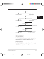
ARBITRATION Phase
The ARBITRATION phase allows one SCSI device to gain control
of the SCSI so that it can initiate or resume an I/O process.
The procedure for an SCSI device to obtain control of the SCSI bus
is as follows:
a) The SCSI device shall first wait for the BUS FREE phase to
occur. The BUS FREE phase detected whenever both the BSY
and SEL signals are simultaneously and continuously false for a
minimum of a bus settle delay.
b) The SCSI device shall wait a minimum of a bus free after
detection of the BUS FREE phase (i.e. after the BSY and SEL
signals are both false for a bus settle delay) before driving any
signal
c) 3)Following the bus free delay in Step(b), the SCSI device may
arbitrate for the SCSI bus by asserting both the BSY signal and its
own SCSI ID, however the SCSI device shall not arbitrate (i.e.
assert the BSY signal and its SCSI ID) if more than a bus settle
delay has passed since the BUS FREE phase was last observed.
3-16
#03.pm5
M3099GX/GH OEM Manual
16
98.2.22, 1:31 PM
d) After waiting at least an arbitration delay (measured from its
assertion of the BSY signal) the SCSI device shall examine the
DATA BUS. If a higher priority SCSI ID bit is true on the
DATA BUS (DB(7) is the highest), then the SCSI devices has
lost the arbitration and the SCSI device may release its signals
and return to Step(a). If no higher priority SCSI ID bit is true on
the DATA BUS, then the SCSI device has won the arbitration
and it shall assert the SEL signal. Any SCSI device other than the
winner has lost the arbitration and shall release the BSY signal
and its SCSI ID bit within a bus clear delay after the SEL signal
becomes true. An SCSI device that loses arbitration may return to
Step(a).
e) The SCSI device that wins arbitration shall wait at least a bus
clear delay plus a bus settle delay after asserting the SEL signal
before changing any signals.
SELECTION Phase
The SELECTION phase allows an initiator to select a target for the
purpose of initiating some target function (e.g., READ or WRITE
command). During the SELECTION phase the I/O signal is
negated so that this phase can be distinguished from the
RESELECTION phase.
The SCSI device that won the arbitration has both the BSY and SEL
signals asserted and has delayed at least a bus clear delay plus a bus
settle delay before ending the ARBITRATION phase. The SCSI
device that won the arbitration becomes an initator by not asserting
the I/O signal.
The initiator shall set the DATA BUS to a value which is the OR of
its SCSI ID bit and the target’s SCSI ID bit and it shall assert the
ATN signal (indicating that a MESSAGE OUT phase is to follow
the SELECTION phase). The initiator shall the wait at least two
deskew delays and release the BSY signal. The initiator shall then
wait at least a bus settle delay before looking for a response from the
target.
The target shall not respond to selection if bad parity is detected.
Also, if more than two SCSI ID bits are on the DATA BUS, the
target shall not respond to selection.
M3099GX/GH OEM Manual
#03.pm5
17
3-17
98.2.22, 1:31 PM
INTERFACE
No less than two deskew delays after the initiator detects the BSY
signal is true, it shall release the SEL signal and may change the
DATA BUS. The target shall wait unitl the SEL signal is false before
asserting the REQ signal to enter an information transfer phase. (See
ANSI SCSI-2 6.1.3.1 SELECTION Time-out Procedure)
RESELECTION Phase
RESELCTION is an optional phase that allows a target to reconnect
to an initiator for the purpose of continuing some operation that was
previously started by the initiator but was suspended by the
target(i.e., the target disconnected by allowing a BUS FREE phase to
occur before the operation was completed).
RESELECTION
Upon completing the ARBITRATION phase, the winning SCSI
device has both the BSY and SEL signals asserted and has delayed at
least a bus clear delay plus a bus settle delay. The winning SCSI
device becomes a target by asserting the I/O signal. The winning
SCSI device shall also set the DATA BUS to a value that is the
logical OR of its SCSI ID bit and the initiator’s SCSI ID bit. The
target shall wait at least two deskew delays and release the BSY signal.
The target shall wait at least a bus settledelay before looking for a
response from the initiator.
The initiator shall determine that it is reselected when the SEL and
I/O signals and its SCSI ID bit are true and the BSY signal is false
for at least a bus settle delay. The reselected initiator may examine
the DATA BUS in order to determine the SCSI ID of the reselecting
target. The reselected initiator shall then assert the BSY signal within
a selection abort time of its most recent detection of being reselected;
this is required for correct operation of the time-out procedure. The
initiator shall not respond to a RESELECTION phase if bad parity
is detected.
Also, the initiator shall not respond to a RESELECTION phase if
other than two SCSI ID bits are on the DATA BUS.
3-18
#03.pm5
M3099GX/GH OEM Manual
18
98.2.22, 1:31 PM
After the target detects the BSY signal is true, it shall also assert the
BSY signal and wait at least two deskew delays and then release the
SEL signal. The target may then change the I/O signal and the
DATA BUS. After the reselected initiator detects the SEL signal is
false, it shall release the BSY signal. The target shall continue
asserting the BSY signal until it relinquished the SCSI bus. (See
ANSI SCSI-2 6.1.4.2. RESELECTION Time-out Procedure)
Information Transfer Phases
NOTE: The COMMAND, DATA, STATUS, and MESSAGE
phases are all grouped together as the information transfer phases
because they are all used to transfer data or control information via
the DATA BUS. The actual content of the information is beyond
the scope of this section.
The C/D, I/O, and MSG signals are used to distinguish between the
different information transfer phases(see Table 3.6). The target
drives these three signals and therefore controls all changes from one
phase to another. The initiator can request a MESSAGE OUT phase
by asserting the ATN signal, while the target can cause the BUS
FREE phase by releasing the MSG, C/D, I/O, and BSY signals.
The information transfer phases use one or more REQ/ACK
handshakes to control the information transfer. Each REQ/ACK
handshake allows the transfer of one byte of information. During the
information transfer phases the BSY signal shall remain true and the
SEL signal shall remain false. Additionally, during the inforamtion
transfer phases, the target shall continuously envelope the REQ/ACK
handshake(s) with the C/D, I/O, and MSG signals in such a manner
that these control signals are valid for a bus settle delay before the
assertion of the REQ signal of the first handshake and remain valid
until after the negation of the ACK signal at the end of the
handshake of the last transfer of the phase.
M3099GX/GH OEM Manual
#03.pm5
19
3-19
98.2.22, 1:31 PM
INTERFACE
Table 3.6 Information Transfer Phases
Signal
Phase Name
MSG C/D I/O
0
0
0
0
1
1
1
1
0
0
1
1
0
0
1
1
0
1
0
1
0
1
0
1
DATA OUT
DATA IN
COMMAND
STATUS
*
*
MESSAGE OUT
MESSAGE IN
Direction of Transfer
Comment
Initiator to target
Data
Initiator from target
Phase
Initiator to target
Initiator from target
Initiator to target
Initiator to target
Message
Phase
Key: 0 = False, 1 = True, * = Reserved for future standardization
Asynchronous Information Transfer
The target shall control the direction of information transfer by
means of the I/O signal. When the I/O signal is true, information
shall be transferred from the target to the initiator. When the I/O
signal is false, information shall be transferred from the initiator to
the target. If the I/O signal is true (transfer to the initiator), the
target shall first drive the DB(7-0,P) signals to their desired values,
delay at least one deskew delay plus a cable skew delay, then assert
the REQ signal. The DB(7-0,P) signals shall remain valid until the
ACK signal is true at the target. The initiator shall read the DB(70,P) signals after the REQ signal is true, then indicate its acceptance
of the data by asserting the ACK signal. When the ACK signal
becomes true at the target, the target may change or release the
DB(7-0,P) signals and shall negate the REQ signal. After the REQ
signal is false the initiator shall then negate the ACK signal. After the
ACK signal is false the target may continue the transfer by dividing
the DB(7-0,P) signals and asserting the REQ signal, as described
above.
3-20
#03.pm5
M3099GX/GH OEM Manual
20
98.2.22, 1:31 PM
If the I/O signal is false (transfer to the target) the target shall request
information by asserting the REQ signal. The initiator shall drive the
DB(7-0,P) signals to their desired values, delay at least one deskew
delay plus a cable skew delay and assert the ACK signal. The initiator
shall continue to drive the DB(7-0,P) signals until the REQ signal is
false. When the ACK becomes true at the initiator, the initiator may
change or release the DB(7-0,P) signals and shall negate the ACK
signal. After the ACK signal is false the target may continue the
transfer by asserting the REQ signal, as described above.
Synchronous Data Transfer
Synchronous data transfer is optional and is only used data phases. It
shall be used in a data phase if a synchronous data transfer agreement
has been established (see SYCHRONOUS DATA TRANSFER
REQUEST Message). The agreement specifies the REQ/ACK offset
and the minimum transfer period.
The REQ/ACK offset specifies the maximum number of REQ pulses
that can be sent by the target in advance of the number of ACK
pulses received from initiator, establishing a pacing mechanism. If
the number of REQ pulses exceeds the number of ACK pulses by the
REQ/ACK offset, the target shall not assert the REQ signal until
after the leading edge of the next ACK pulse is received. A
requirement for successful completion of the data phase is that the
number of ACK and REQ pulses be equal.
The target shall assert the REQ signal for a minimum of an assertion
period. The target shall then wait at least the greater of a transfer
period from the last transition of the REQ signal to true or a
minimum of a negation period from the last transition of the ACK
signal to false before asserting the ACK signal.
The initiator shall send one pulse on the ACK signal for each REQ
pulse received. The ACK signal may be asserted as soon as the
leading edge of the corresponding REQ pulse has been received. The
Initiator shall assert the ACK signal for a minimum of an assertion
period. The initiator shall wait at least the greater of transfer period
from the last transition of the ACK signal to true or for a minimum
of a negation period from the last transition of the ACK signal to
false before asserting the ACK signal.
M3099GX/GH OEM Manual
#03.pm5
21
3-21
98.2.22, 1:31 PM
INTERFACE
If the I/O signal is true (transfer to the initiator), the target shall first
drive the DB(7-0,P) signals to their desired values, wait at least one
deskew delay plus one cable skew delay, then assert the REQ signals.
The DB(7-0,P) signals shall be held valid for a minimum of one
deskew delay plus one cable skew delay plus one hold time after the
assertion of the REQ signal. The target shall assert the REQ signal
for a minimum of an assertion period. The target may then negate
the REQ signals within one hold time of the transition of the REQ
signal to true. The initiator shall then respond with an ACK pulse.
If the I/O signal is false (transfer to the target), the initiator shall
tranfer one byte for each REQ pulse received. After receiving the
leading edge of a REQ pulse, the initiator shall first drive the DB(70,P) signals to their desired values, delay at least one deskew delay
plus one cable skew delay, then assert the ACK signal. The initiator
shall hold the DB(7-0,P) signals valid for at least one deskew delay
plus one cable skew delay plus one hold time after the assertion of
the ACK signal. The initiator shall assert the ACK signal for a
minimum of an assertion period. The initiator may then negate the
ACK signal and may one hold time of the transition of the ACK
signal to true.
COMMAND Phase
The COMMAND phase allows the target to request command
information from the initiator.
The target shall assert the C/D signal and negate the I/O and MSG
signals during the REQ/ACK handshake(s) of this phase.
Data Phase
The data phase is a term that encompasses both the DATA IN phase
and the DATA OUT phase.
3-22
#03.pm5
M3099GX/GH OEM Manual
22
98.2.22, 1:31 PM
DATA IN Phase
The DATA IN phase allows the target to request that data be sent to
the initiator from the target.
The target shall assert the I/O signal and negate the C/D and MSG
signals during the REQ/ACK handshake(s) of this phase.
DATA OUT Phase
The DATA OUT phase allows the target to request that data be sent
from the target to the initiator.
The target shall negate the C/D, I/O, and MSG signals during the
REQ/ACK handshake of this phase.
STATUS Phase
The STATUS phase allows the target to request that status
information be sent from the target to the initiator.
The target shall assert the C/D and I/O signals and negate the MSG
signal during the REQ/ACK handshake of this phase.
Message Phase
The message phase is a term that references either a MESSAGE IN,
or a MESSAGE OUT phase. Multiple messages may be sent during
either phase. The first byte transferred in either of these phases shall
be either a single-byte message or the first byte of a multiple-byte
message. Multiple-byte messages shall be wholly contained within a
single message phase.
MESSAGE IN Phase
The MESSAGE IN phase allows the target to request that message(s)
be sent to the initiator from the target.
The target shall assert the C/D, I/O, and MSG signals during the
REQ/ACK handshake(s) of this phase.
M3099GX/GH OEM Manual
#03.pm5
23
3-23
98.2.22, 1:31 PM
INTERFACE
MESSAGE OUT Phase (See ANSI SCSI-2 6.1.9.2 for details)
The MESSAGE OUT phase allows the target to request that
message(s) be sent from the initiator to the target. The target invokes
this phase in response to the attention condition created by the
initiator.
The target shall assent the C/D and MSG signals and negate the I/O
signal during the REQ/ACK handshake(s) of this phase. The target
shall handshake byte(s) in this phase until the ATN signal is negated,
except when rejecting a message.
If the target receives all of the message byte(s) successfully (i.e., no
parity errors), it shall indicate that it does not wish to retry by
changing to any information transfer phase other than the
MESSAGE OUT phase and transfer at least one byte. The target
may also indicate that it has successfully received the message byte(s)
by changing to the BUS FREE phase (e.g., ABORT or BUS
DEVICE RESET messages).
SCSI Bus
Conditions
The SCSI bus has two asynchronous conditions; the attention
condtion. These conditions cause the SCSI device to perform ceratin
actions and alter the phase sequence.
Attention Condition
The attention condition allows an initiator to inform a target that
the initiator has a message ready. The target may get this message by
performing a MESSAGE OUT phase.
The initiator creates the attention condition by asserting ATN at any
time except during the ARBITRATION or BUS FREE phases.
The initiator shall negate the ATN signal at least two deskew delays
before asserting the ACK signal while transferring the last byte
transferred in a bus phase for the attention condition to be honored
before transition to a new bus phase. Asserting the ATN signal later
might not be honored until a later bus phase and then may not result
in the expected action. See ANSI SCSI-2 6.2.1 for details.
3-24
#03.pm5
M3099GX/GH OEM Manual
24
98.2.22, 1:31 PM
Reset Condition
The reset condition is used to immediately clear all SCSI devices
from the bus. This condition shall take precedence over all other
phases and condtions. Any SCSI device may create the reset
condition by asserting the RST signal for a minimum of a reset hold
time.
All SCSI devices shall release all SCSI bus signals (except the RST
signal) within a bus clear delay of the transition of the RST signal to
true. The BUS FREE phase always the reset condition.
The effect of the reset condition on I/O processes which have not
completed, SCSI device reservations, and SCSI device operation
modes is determined by whether the SCSI device has implemented
the hard reset alternative or the soft reset alternative (one of which
shall be implemented) as defined in ANSI SCSI-2 6.2.2.1 and
6.2.2.2. The hard and soft reset alternative is implemented is
provided in the SftRe bit of the INQUIRY data. This scanner
supports Hard Reset alternative as below.
Hard Reset Alternative:
1) Clear all I/O process including queued I/O process.
2) Release all SCSI device reservations.
3) Return any SCSI device operation modes to their appropriate
initial conditions, similar to those conditions that would be
found after a normal power-on reset. MODE SELECT
conditions shall be restored to their last saved values if saved
values have been established. MODE SELECT conditions for
which no values have been save shall be returned to their default
values.
4) Unit attention condition shall be set.
Note: I/O process queuing in (1) and parameter saving in (3) are
not supported in this scanner.
M3099GX/GH OEM Manual
#03.pm5
25
3-25
98.2.22, 1:31 PM
INTERFACE
SCSI Bus Phases
Sequences
The order in which phases are used on the SCSI bus follows a
prescribed sequence.
The reset condition can abort any phase and is always followed by
the BUS FREE phase. Also any other phase can be followed by the
BUS FREE phase but many such instances are error conditions.
The additional allowable sequences shall be as shown in Figure 3.5.
The normal progression is from the BUS FREE phase to
ARBITRATION, from ARBITRATION to SELECTION or
RESELECTION, and from SELECTION or RESELECTION to
one or more of the information tranfer phases (COMMAND,
DATA, STATUS, or MESSAGE). The final information transfer
phase is normally the MESSAGE IN phase where a
DISCONNECT, or COMMAND COMPLETE message is
transferred, followed by the BUS FREE phase.
Reset or
protocol
error
MESSAGE OUT
BUS FREE
SELECTION
COMMAND
ARBITRATION
DATA IN or
DATA OUT
RESELECTION
STATUS
MESSAGE IN
Figure 3.5 Phase Sequence
3-26
#03.pm5
M3099GX/GH OEM Manual
26
98.2.22, 1:31 PM
Commands (See
ANSI SCSI-2 7)
A command is communicated by sending a command descriptor
block to the target. For several commands, the command descriptor
block is accompanied by a list of parameters sent during the DATA
OUT phase. The command descriptor block always has an operation
code as its first byte and a control byte as its last byte.
INTERFACE
Reserved (See ANSI SCSI-2 7.1.1)
Reserved bits, fields, bytes, and code values are set aside for future
standardization. Their use and interpretation may be specified by
future extensions to ANSI SCSI standard. A reserved bit, field, or
byte shall be set to zero, or in accordance with a future extension to
this standard. A target that receives a reserved bit, field, or byte that
is not zero or receives a reserved code value shall terminate the
command with CHECK CONDITION status and the sense key
shall be set to ILLEGAL REQUEST.
Logical Unit Number
The logical unit number is defined in the IDENTIFY message. The
target shall ignore the logical unit number specified within the
command descriptor block if an IDENTIFY message was received.
This scanner supports Logical Unit Number 000b only. Followings
shows target’s response to selection of invalid logical unit.
• In response to an INQUIRY command, the target shall return the
INQUIRY data with the peripheral qualifier set to the value
required.
• In response to any other command except REQUEST SENSE, the
target shall terminate the command with CHECK CONDITION
status.
• In response to an REQUEST SENSE command, the target shall
return sense data. The sense key shall be set to ILLEGAL
REQUEST and the additional sense code shall be set to
LOGICAL UNIT NOT SUPPORTED.
M3099GX/GH OEM Manual
#03.pm5
27
3-27
98.2.22, 1:31 PM
Transfer Length
The transfer length field specifies the amount of data to be
transfered, usually number of blocks. The block length is this scanner
is 1byte. In command that use multiple bytes for the transfer length,
a transfer length of zero indicates that no data transfer shall take
place. A value of one or greater indicates the number if blocks that
shall be transferred.
Allocation Length
The allocation length field specifies the maximum number of bytes
that an initiator has a allocated for returned data. An allocation
length of zero indicates that no data shall be transferred. This
condition shall not be considered as an error. The target shall
terminate the DATA IN phase when allocation length bytes have
been transferred or when all available data have been transferred to
the initiator, whichever is less. The allocation length is used to limit
the maximum amount of data(e.g. sense data, mode data, etc)
returned to initiator.
Control field
The control field is the last byte of every command descriptor block.
The control field is defined in ANSI SCSI-2 7.2.7. In this scanner,
this field is not used. Any field in this byte is regarded as Reserved.
3-28
#03.pm5
M3099GX/GH OEM Manual
28
98.2.22, 1:31 PM
Table 3.7 Operation Code Types
Command
Operation Description
Code(hex)
RESERVE UNIT
16
Reserve a logical unit
RELEASE UNIT
17
Release a previously reserved logical
unit
INQUIRY
12
Requests information regarding
parameters of target and its attached
peripheral device(s).
REQUEST SENSE
03
Requests the target transfer sense
data to the initiator
SEND DIAGNOSTIC 1D
Request the target to perform
diagnostic operations on itself
ENDORSER
C1
Start/Stop endorser function
TEST UNIT READY
00
Check if the logical unit is ready
SET WINDOW
24
Specify windows within the
scanning range of the device.
SEND
2A
Transfers data from initiator to
target
OBJECT POSITION
31
Provids positioning functions (ADF
Feed in/out)
SCAN
18
Requests the target begin a scan
operation
READ
28
Requests the target transfer data to
the initiator
MODE SELECT(6)
15
Specify logical unit, peripheral
device parameters from the initiator
to the target
MODE SENSE(6)
1A
Report parameters from the target to
the initiatot
M3099GX/GH OEM Manual
#03.pm5
29
3-29
98.2.22, 1:31 PM
INTERFACE
RESERVE UNIT Command
The RESERVE UNIT command (Table 3.8) is used to reserve
logical unit for the exclusive use of the requesting initiator to another
specified SCSI device.
Table 3.8 RESERVE UNIT Command
Bit
Byte
7
6
5
4
3
2
1
0
0
Operation Code (16h)
1
Logical Unit Number 3rdPty Third Party Device ID Reserved
2
Reserved
3
Reserved
4
Reserved
5
Control
The RESERVE UNIT and RELEASE UNIT commands provide the
basic mechanism for contention resolution in multiple-initiator
systems.
This command requests that the entire logical unit be reserved for
the exclusive use of the initiator until the reservation is superseded by
another valid RESERVE UNIT command from the initiator that
made the reservation or until released by a BUS DEVICE RESET
message from any initiator, by a hard reset condition, or by a power
on cycle. The reservation shall not be granted if the logical unit is
reserved by another initiator. It shall be permissible for an initiator to
reserved a logical unit that is currently reserved by that initiator.
If the logical unit is reserved for another initiator, the target shall
return RESERVATION CONFLICT status.
3rdPty:
0b (Reserved)
Third Party Device ID: 000b (Reserved)
3-30
#03.pm5
M3099GX/GH OEM Manual
30
98.2.22, 1:31 PM
Superseding Reservations
An initiator that currntly has a logical unit reserved may modify the
current reservation by issuing another RESERVE UNIT command
to the same logical unit. The superseding reservation shall release the
current reservation if the superseding reservation request is granted.
If the superseding resrvation cannot be granted because of conflicts
with a previous reservation (other than the current reservation), then
the target shall return RESERVATION CONFLICT status.
See ANSI SCSI-2 9.2.10.2 for details.
RELEASE UNIT Command
The RELEASE UNIT command (Table 3.9) is used to release
previously reserved logical units for the requesting initiator to
another specified SCSI device.
Table 3.9 RELEASE UNIT Command
Bit
Byte
7
6
5
4
3
2
1
0
0
Operation Code (17h)
1
Logical Unit Number 3rdPty Third Party Device ID Reserved
2
Reserved
3
Reserved
4
Reserved
5
Control
The RESERVE UNIT and RELEASE UNIT commands provide the
basic mechanism for contention resolution in multiple-initiator
systems.
If a valid reservation exists for the I_T_L nexus, the target shall
release the reservation and return GOOD status.
M3099GX/GH OEM Manual
#03.pm5
31
3-31
98.2.22, 1:31 PM
INTERFACE
A reservation may only be released by the initiator that made it. It is
not an error to attempt to release reservation that is currently valid or
is held by another initiator. In this case, the target shall return
GOOD status without altering any other reservation.
3rdPty:
0b (Reserved)
Third Party Device ID: 000b (Reserved)
TEST UNIT READY Command
The TEST UNIT READY command (Table 3.10) provides a means
to check if the logical unit is ready. This is not a request for a selftest.
If the logical unit would accept an appropriate command without
returning CHECK CONDITION status, this command shall return
a GOOD status. If the logical unit cannot become operational the
target shall return CHECK CONDITION status with a sense key of
NOT READY.
Table 3.10 TEST UNIT READY Command
Bit
Byte
0
1
7
6
5
4
3
2
1
0
Operation Code (00h)
Logical Unit Number
Reserved
2
Reserved
3
Reserved
4
Reserved
5
Control
INQUIRY Command (See ANSI SCSI-2 7.2.5)
The INQUIRY command (Table 3.11) requests that information
regarding parameters of the target and its attached peripheral
device(s) be sent to the initiator. An option allows the inititor to
request additional information about the target or logical unit (See
ANSI SCSI-2 7.2.5.2 Vital Product Data).
3-32
#03.pm5
M3099GX/GH OEM Manual
32
98.2.22, 1:31 PM
Table 3.11 INQUIRY Command
Bit
Byte
7
0
1
6
5
4
3
2
1
0
Operation Code (12h)
Logical Unit Number
Reserved
2
Page Code
3
Reserved
4
Allocation Length
5
Control
EVPD
INTERFACE
EVPD (Enable Vital Product Data):
This bit of one specifies that the target shall return the optional vital
product data specified by the page code field. If the target does not
support vital product data and this bit is set to one, the target shall
return CHECK CONDITION status with the sense key set to
ILLEGAL REQUEST and an additional sense code of INVALID
FIELD IN CDB.
This bit of zero specifies that the target shall return the standard
INQUIRY data. If the page code field not zero, the target shall
return CHECK CONDITION status with the sense key set to
ILLEGAL REQUEST and an additional sense code of INVALID
FIELD IN CDB.
Page Code:
This field specifies which page of vital product data information the
target shall return (see ANSI SCSI-2 7.3.4). The supported vital
product data in this scanner is Page Code F0h.
The INQUIRY command shall return CHECK CONDITION
status only when the target cannot return the requested INQUIRY
data.
M3099GX/GH OEM Manual
#03.pm5
33
3-33
98.2.22, 1:31 PM
If an INQUIRY command is received from an initiator with a
pending unit attention condition (i.e., before the target reports
CHECK CONDITION status), the target shall perform the
INQUIRY command and shall not clear the unit attention
condition.
Standard INQUIRY Data (See ANSI SCSI-2 7.2.5.1)
This standard INQUIRY data (Table 3.12) contains 36 required
bytes, followed by a variable number of vendor-specific parameters.
Bytes 56 through 95, if returned, are reserved for future
standardization.
3-34
#03.pm5
M3099GX/GH OEM Manual
34
98.2.22, 1:31 PM
Table 3.12 Standard INQUIRY Data Format
Bit
Byte
0
7
6
4
Peripheral Qualifier
1
RMB
2
ISO Version
3
5
3
2
0
Peripheral Device Type
Device-Type Modifier
ECMA Version
AENC
ANSI Approved Version
Reserved
4
Additional Length (n-4)
5
Reserved
6
Reserved
7
1
RelAdr WBus32 WBus16
Sync
Linked Reserved CmdQue SftRe
8
(MSB)
––– –––
15
Vendor Identification
–––
(LSB)
16 (MSB)
– –␣ – – – –
31
Product Identification
–––
(LSB)
32 (MSB)
––– –––
35
Product Revision Level
–––
(LSB)
36
–␣ –␣ –
55
Vendor Specific
56
–␣ –␣ –
95
Reserved
Vendor-Specific Parameters
96
–␣ –␣ –
n
Vendor Specific
M3099GX/GH OEM Manual
#03.pm5
35
3-35
98.2.22, 1:32 PM
INTERFACE
The peripheral qualifier and peripheral device type fields identify the
device currently connected to the logical unit. If the target is not
capable of supporting a device on this logical unit, this field shall be
set to 7Fh (peripheral qualifier set to 011b and peripheral device type
set to 1Fh).
Peripheral Qualifier:
000b(Connected)
Peripheral Device Type:
06h(Scanner Device)
RMB(Removable Medium Bit): 0b(not supported).
Device Type Modifier:
0000000b(not supported)
ISO Version:
00b(does not claim compliance
with ISO)
ECMA Version:
000b(does not claim compliance
with ECMA)
ANSI Approved Version:
2h(SCSI-2, if approved)
AENC(Asynchronous Event Notification Capability):
0b(Reserved)
TrmIOP(Terminate I/O Process):
0b(not supported. see ANSI SCSI2 5.6.22)
Response Data Format:
2h(INQUIRY Data Format is
defined in SCSI-2)
Additional Length:
91(n=95)
This field shall specify the length in bytes of the parameters. If the
allocation length of the command descriptor block is too small to
transfer all of the parameters, the additional length shall not be
adjusted to reflect the truncation.
RelAdr(Relative Addressing):
Wbus32(Wide Bus 32):
Wbus16(Wide Bus 16):
Sync(Synchronous Transfer):
Linked(Linked Command):
CmdQue(Command Queuing):
SftRe(Soft Reset):
Vendor Identification:
3-36
#03.pm5
0b(not supported)
0b(not supported)
0b(not supported)
1b(synchronous transfer supported)
0b(not supported)
0b(not supported)
0b(Hard Reset)
“FUJITSU “
M3099GX/GH OEM Manual
36
98.2.22, 1:32 PM
Product Identification: (M3099GH)
“M3099GHdm
”
default (Duplex, CMP2 equivalent)
“M3099GHdem
”
with ENDORSER option
“M3099GHdim
”
with IPC2 option
“M3099GHdeim
”
with ENDORSER, IPC2 options
Product Identification: (M3099GX)
“M3099Gdm
”
default (Duplex, CMP2 equivalent)
“M3099Gdem
”
with ENDORSER option
“M3099Gdim
”
with IPC2 option
“M3099Gdeim
”
with ENDORSER, IPC2 options
Product Identification: (M3096G)
“M3096Gm
”
default
“M3096Gim
”
with IPC2 option
Product Revision Level:
“01 ”(Black and White Binary)
Vital Product Data
JBMS(Japanese Business Machines Standard) is defining standard
Vital Product Data. (See JBMS-40-1990) Fujitsu Scanners also
support this data by adding Fujitsu original extention. JBMS-401990 uses 30 Bytes as standard VPD to describe specification and
functions.This data is obtained by setting EVPD bit to 1 and Page
Code to F0h in INQUIRY command.
If Product Identification has changed to M3096G or M3099G in
Off-line SETUP mode following data are returned. The ‘d’ which
indicates Duplex, and ‘e’ which indicates ENDORSER are not
returned. See Chapter 4 Operator panel.
M3099GX/GH OEM Manual
#03.pm5
37
3-37
98.2.22, 1:32 PM
INTERFACE
Table 3.13 Standard VPD Page Format
Bit
Byte
7
6
5
4
3
2
0
Peripheral Device Type
1
Page Number(F0h)
2
J Version
3
Reserved
4
Page Length (m-5)
5
1
0
(MSB)
Basic X Resolution
(LSB)
(MSB)
Basic Y Resolution
(LSB)
6
7
8
9
10
Res Step X
Res Step Y
(MSB)
Maximum X Resolution
(LSB)
(MSB)
Maximum Y Resolution
(LSB)
(MSB)
Minimum X Resolution
(LSB)
(MSB)
Minimum Y Resolution
(LSB)
(MSB)
Standard Resolution
(LSB)
(MSB)
Window Width
(LSB)
(MSB)
Window Length
(LSB)
11
12
13
14
15
16
17
18
19
20
23
24
27
3-38
#03.pm5
28
Function
29
Reserved
30
to
n
Vendor Unique Parameter Byte(s)
M3099GX/GH OEM Manual
38
98.2.22, 1:32 PM
Peripheral Device:
Page Number:
J Version:
Page Length:
Basic X Resolution:
Basic Y Resolution:
Res Step X:
Res Step Y:
Maximum X Resolution:
Maximum Y Resolution:
Minimum X Resolution:
Minimum Y Resolution:
Standard Resolution:
06h(Image Scanner)
F0h(Page Code)
02h(JBMS 0.2)
95(m=100)
200(200dpi)
200(200dpi)
00h(Variable Resolution)
00h(Variable Resolution)
400(400dpi with/without IPC2)
400(400dpi with/without IPC2)
200(without IPC2)/50(with IPC2)
200(without IPC2)/50(with IPC2)
01D0h(without IPC2)/FFF0h(with IPC2)
This field indicates available resolution bit is set as as described in
Table 3.14. This is applied to only for main-scan direction.
Table 3.14 Standard Resolution (unit:Pixel/Inch)
Bit
Byte
7
6
5
4
3
2
1
0
17
60
75
100
120
150
160
180
200
18
240
300
320
400
480
600
800
1200
Window Width:
Window Length:
00000980h(2432 dot) for M3099GX
000006C0h(1728dot) for M3099GH
00000D80h(3456 dot)
Window Width and Window Length fields are maximum width and
length those are available by the scanner. The units are pixels
counted by the basic resolution.
Function:
00000110b
Function field specifies functions supported by the scanner. Each bit
is set to 1 corresponding to Table 3.15.
M3099GX/GH OEM Manual
#03.pm5
39
3-39
98.2.22, 1:32 PM
INTERFACE
Table 3.15 Function
Bit
Description
Bit 0
Data Over Flow
Scanners that will cause data over flow sets this bit to 1. Image
scanners that will not cause data over flow set this bit to 0.
Support of Start Switch is not specified.
Bit 1
Binary (Black and White)
Scanners support Black and White set this bit to 1. Scanners do
not support Black and White set this bit to 0.
Bit 2
Dither/Halftone
Scanners support Dither/Halftone set this bit to 1. Scanners do
not support Dither/Halftone set this bit to 0.
Bit 3
Grayscale
Scanners support Grayscale set this bit to 1. Scanners do not
support Grayscale set this bit to 0.
Steps of gray is not specified.
Bit 4
Reserved (Bit 4 to 7 are Reserved in JBMS)
Bit 5
Binary (RGB Color)
Scanners support (RGB Color) set this bit to 1. Scanners do not
support (RGB Color) set this bit to 0.
Bit 6
Dither/Halftone(RGB Color)
Scanners support Dither/Halftone (RGB Color) set this bit to 1.
Scanners do not support Dither/Halftone (RGB Color)set this
bit to 0.
Bit 7
Grayscale(RGB Color)
Scanners support Grayscale(RGB Color) set this bit to 1.
Scanners do not support Grayscale(RGB Color) set this bit to 0.
Steps of gray is not specified.
*) Data Over Flow means when receipt of data by the initiator is
too slow, data buffer of image scanner is filled and data is not
guranteed.
Fujitsu further defines own Vital Product Data using Vendor
Specific field of JBMS. This extended Vital Product Data is used by
Device Driver to confirm which functions are supported. Current
defined data is totally 100 bytes but it will be expanded by future
functions.
3-40
#03.pm5
M3099GX/GH OEM Manual
40
98.2.22, 1:32 PM
Table 3.16 Standard VPD Page Extended Format
Bit
Byte
7
6
5
4
3
30
Reserved
31
Reserved
32
(MSB)
2
1
(LSB)
(MSB)
Buffering Capability
37
38
(LSB)
(MSB)
Implemented Standard Command
41
42
INTERFACE
Physical Function
33
34
0
(LSB)
Implemented Vendor Specific Command
49
50
Implemented Vendor Unique Parameter
81
82
Image Control Function
87
88
Image Processing Function
89
90
Compression Function
91
92
Endorser Function
93
94
Barcode Function
97
95
Reserved
100
M3099GX/GH OEM Manual
#03.pm5
41
3-41
98.2.22, 1:32 PM
Physical Function:
10010010 00001000b(without
ENDORSER)
10011010 00001000b(with
ENDORSER)
Physical Function field of each bit indicates Physical variated
functions.
Table 3.17 Physical Function
Byte
Bit
Description
32
1XXXXXXXb
X1XXXXXXb
XX1XXXXXb
XXX1XXXXb
XXXX1XXXb
XXXXX1XXb
XXXXXX1Xb
XXXXXXX1b
Automatic Document Feeder
Flatbed
Tranceparency
Duplex
Endorser
Barcode
Operator Panel
Reserved
33
0000nnnnb
Bits of ADC
Buffering Capability:
0080 0000h(8M Bytes)
Buffering Capability field indicates that interface buffering capability
in bytes.
Implemented Standard Command:
0000 0000 0000 0000 1110 1101 1011
1111b = 0000EDBFh
Implemented Standard Command field of each bit indicates
supported SCSI command as Table 3.18.
3-42
#03.pm5
M3099GX/GH OEM Manual
42
98.2.22, 1:32 PM
Table 3.18 Implemented Standard Command
Bit
0
1
2
3
4
5
6
7
8
9
10
11
12
13
14
15
16
17
18
19
20
21
22
23
24
25
26
27
28
29
30
31
Command
TEST UNIT READY
REQUEST SENSE
INQUIRY
MODE SELECT(6)
RESERVE UNIT
RELEASE UNIT
COPY
MODE SENSE(6)
SCAN
RECEIVE DIAGNOSTIC RESULTS
SEND DIAGNOSTIC
SET WINDOW
GET WINDOW
READ
SEND
OBJECT POSITION
GET DATA BUFFER STATUS
COMPARE
COPY AND VERIFY
WRITE BUFFER
READ BUFFER
CHANGE DEFINITION
LOG SELECT
LOG SENSE
MODE SELECT(10)
MODE SENSE(10)
Reserved
Reserved
Reserved
Reserved
Reserved
Reserved
Code
00h
03h
12h
15h
16h
17h
18h
1Ah
1Bh
1Ch
1Dh
24h
25h
28h
2Ah
31h
34h
39h
3Ah
3Bh
3Ch
40h
4Ch
4Dh
55h
5Ah
M3099GX/GH OEM Manual
#03.pm5
43
M
M
M
O
M
M
O
O
O
O
M
M
O
M
O
O
O
O
O
O
O
O
O
O
O
O
INTERFACE
3-43
98.2.22, 1:32 PM
Implemented Vendor Specific Command:
CXh = 0000h, DXh = 0000h, EXh = 0000h, FXh = 0000h
(without ENDORSER)
CXh = 0002h, DXh = 0000h, EXh = 0000h, FXh = 0000h
(with ENDORSER)
Implemented Vendor Specific Command field indicates vendor
specific command implemented by the scanner. This field consists of
4 sets of 2 bytes structure as Table 3.19. Each bit position in these
fields indicates lower 4 bits of the command code.
Implemented Vendor Specific Command field is subdivided to CXh,
DXh, EXh, FXh as Table 3.20.
Table 3.19 2 bytes structure
Bit
Byte
7
6
5
4
3
2
1
0
0
bit 15 bit 14 bit 13 bit 12 bit 11 bit 10
bit 9
bit 8
1
bit 7
bit 1
bit 0
bit 6
bit 5
bit 4
bit 3
bit 2
Table 3.20 Implemented Vendor Specific Command
Bytes
Description
42, 43
Vendor Specific Command field - CXh
44, 45
Vendor Specific Command field - DXh
46, 47
Vendor Specific Command field - EXh
48, 49
Vendor Specific Command field - FXh
Table 3.21 Implemented Vendor Specific Command
Field&Bit Command
Code
CXh 0
SET SUBWINDOW
C0h
V
ENDORSER
C1h
V
1
DXh
EXh
FXh
3-44
#03.pm5
M3099GX/GH OEM Manual
44
98.2.22, 1:32 PM
Vendor Unique Parameter:
See Table 3.22
Vendor Unique Parameter field indicates supported Vendor Unique
Parameter pages defined in SET WINDOW command. Vendor
Unique Parameter field consists of 16 sets of 2 bytes structure as
Table 3.22.Vendor Unique Parameter field are subdivided to fields
0Xh to FXh.
Table 3.22 Vendor Unique Parameter
Bytes
Description
Value
50, 51
Vendor Unique Parameter - 0Xh
0001h
52, 53
Vendor Unique Parameter - 1Xh
0000h
54, 55
Vendor Unique Parameter - 2Xh
0000h
56, 57
Vendor Unique Parameter - 3Xh
0000h
58, 59
Vendor Unique Parameter - 4Xh
0000h
60, 61
Vendor Unique Parameter - 5Xh
0000h
62, 63
Vendor Unique Parameter - 6Xh
0000h
64, 65
Vendor Unique Parameter - 7Xh
0000h
66, 67
Vendor Unique Parameter - 8Xh
0000h
68, 69
Vendor Unique Parameter - 9Xh
0000h
70, 71
Vendor Unique Parameter - AXh
0000h
72, 73
Vendor Unique Parameter - BXh
0000h
74, 75
Vendor Unique Parameter - CXh
0000h
76, 77
Vendor Unique Parameter - DXh
0000h
78, 79
Vendor Unique Parameter - EXh
0000h
80, 81
Vendor Unique Parameter - FXh
0000h
Image Control Function field indicates supplementary information
on SET WINDOW arameter. Image Control Function field is
subdivided to Brightness Steps, Threshold Steps, Contrast Steps,
Number of resident Dither, Number of registrable Dither, Number
of resident Gamma Function, Number of registrable Gamma
Function as Table 3.23.
M3099GX/GH OEM Manual
#03.pm5
45
3-45
98.2.22, 1:32 PM
INTERFACE
Brightness Step:
FFh(255 steps)
Brightness Step field indicates available steps of the Brightness. If
zero is pecified, Brightness Control is not supported.
Threshold Step:
FFh(255 steps)
Threshold Step field indicates available steps of the Threshold. If
zero is pecified, Threshold Control is not supported.
Contrast Step:
FFh(255 steps)
Contrast Step field indicates available steps of the Contrast. If zero is
pecified, Contrast Control is not supported.
Number of Resident Dither:
0100xxxxb(4 patterns)
Number of Resident Dither field indicates number of resident
Dither patterns in 4 bits. If zero is specified no dither pattern is
available.
Number of Registerable Dither: xxxx1000b(8 patterns)
Number of Registerable Dither field indicates registrable dither
patterns in 4 bits. If zero is specified no dither pattern is registrable.
Number of Resident Gamma Function: 0100xxxxb(4 patterns)
Number of Resident Gamma Function field indicates number of
resident gamma functions in 4 bits. If zero is specified no gamma
function is available.
Number of Registrable Gamma Function: xxxx1000b(8 patterns)
Number of Registrable Gamma Function field indicates registrable
gamma functions in 4 bits. If zero is specified no gamma function is
registrable.
3-46
#03.pm5
M3099GX/GH OEM Manual
46
98.2.22, 1:32 PM
Table 3.23 Image Control Function
Byte
82
83
84
85
86
87
Bit
nnnnnnnnb
nnnnnnnnb
nnnnnnnnb
00000000b
nnnnXXXXb
XXXXnnnnb
nnnnXXXXb
XXXXnnnnb
Description
Brightness Steps
Threshold Steps
Contrast Steps
Reserved
Number of resident Dither
Number of registrable Dither
Number of resident Gamma Function
Number of registrable Gamma Function
Image Processing Function: 10000001 01000000b(without IPC2)
11111111 01000000b(with IPC2)
Image Processing function field of each bit indicates supported
Image Processing function.
Table 3.24 Image Processing Function
Byte
88
89
Bit
1XXXXXXXb
X1XXXXXXb
XX1XXXXXb
XXX1XXXXb
XXXX1XXXb
XXXXX1XXb
XXXXXX1Xb
XXXXXXX1b
1XXXXXXXb
X1XXXXXXb
XX1XXXXXb
XXX1XXXXb
XXXX1XXXb
XXXXX1XXb
XXXXXX1Xb
XXXXXXX1b
Description
Reverse Image Format
Dynamic Threshold Circuit
Simplified DTC
Outline Extract
Image Emphasis
Automatic Separation
Mirror Image
White Level Follower
Subwindow
Error Diffusion
Reserved
Reserved
Reserved
Reserved
Reserved
Reserved
M3099GX/GH OEM Manual
#03.pm5
47
3-47
98.2.22, 1:32 PM
INTERFACE
Compression Function: 11100000 00000000b
Compression Function field of each bit indicates Compression
Functions supported by the scanner.
Table 3.25 Compression Function
Byte
90
91
Bit
1XXXXXXXb
X1XXXXXXb
XX1XXXXXb
XXX1XXXXb
XXXX1XXXb
XXXXX1XXb
XXXXXX1Xb
XXXXXXX1b
00000000b
Description
MH
MR
MMR
JBIG
JPEG Base Line System
JPEG Extended System
JPEG Independent Function
Reserved
Reserved
Endorser Function: 00000000 00000000b(without ENDORSER)
10000001 00000000b(with ENDORSER)
Endorser Function field of upper 4bit indicates available endorser
functions and lower 4bit indicates maximum Endorser Identifiers.
Table 3.26 Endorser Function
Byte
92
93
Bit
1XXXXXXXb
X1XXXXXXb
XX1XXXXXb
XXX1XXXXb
XXXXnnnnb
00000000b
Description
Mechanical Endorser
Stamper
Electrical Endorser
Reserved
Maximum Endorser Identifiers
Reserved
Barcode Function: 00000000 00000000 00000000 00000000b
Barcode Function field is reserved.
3-48
#03.pm5
M3099GX/GH OEM Manual
48
98.2.22, 1:32 PM
REQUEST SENSE Command (See ANSI SCSI-2 8.2.14)
The REQUEST SENSE command (Table 3.27) requests that the
target transfer sense data to the initiator.
Table 3.27 REQUEST SENSE Command
Bit
Byte
0
1
7
6
5
4
3
2
1
0
Operation Code (03h)
Logical Unit Number
Reserved
2
Reserved
3
Reserved
4
Allocation Length
5
Control
The sense data:
1) shall be available if a contingent allegiance condition exists for the
I_T_x nexus;
2) shall be available if other information is available in any field;
3) may be available if an unexpected disconnect occurred.
If the target has no other sense data available to return, it shall return
a sense key of NO SENSE and an additional sense code of NO
ADDITIONAL SENSE INFORMATION.
The sense data shall be preserved by the target for the initiator until
retrieved by a REQUEST SENSE command or until the receipt of
any other I/O process for the same I_T_x nexus. Sense data shall be
cleared upon receipt of any subsequent I/O process (including
REQUEST SENSE) to the same I_T_x nexus.
The sense data format for error code 70h(current errors) is
supported.
M3099GX/GH OEM Manual
#03.pm5
49
3-49
98.2.22, 1:32 PM
INTERFACE
Table 3.28 Sense Data Format
Bit
Byte
7
0
Valid
6
5
4
3
2
Segment Number
2
Filemark EOM
3
(MSB)
ILI
Reserved
Sense key
Information
6
(LSB)
7
Additional Sense Length
(MSB)
Command Specific Information
11
(LSB)
12
Additional Sense Code
13
Additional Sense Code Qualifier
14
Field Replaceable Unit Code
15
0
Error Code (70h)
1
8
1
SKSV
Sense Key Specific
17
Valid:
Segment Number:
Filemark:
EOM (End of Medium):
1b(Valid Information)
00h(not supported)
0b(Reserved)
This bit of 1 indicates end of reading a
window.
ILI (Incorrect Length Indicator):
This scanner use this bit when total read image data is not equal to
defined window data.
3-50
#03.pm5
M3099GX/GH OEM Manual
50
98.2.22, 1:32 PM
The sense key, additional sense code and additional sense code
qualifier provide a hierachy of information. The intention of the
hierarchy is to provide a top down approach for an initiator to
determine information relating to the error and exception
conditions. The sense key provides generic categories in which error
and exception condition can be reported. Initiators would typically
use sense keys for high level error recovery procedures. Additional
sense codes provide further detail describing the sense key.
Additional sense code qualifiers add further detail to the additional
sense code. The additional sense code and additional sense code
qualifier can be used by initiators where sophisticated error recovery
procedures require detailed information describing the error and
exception conditions.
The sense key field is mandatory and indicates generic information
describing an error or exception condition. The sense key used are
defined in Table 3.29.
M3099GX/GH OEM Manual
#03.pm5
51
3-51
98.2.22, 1:32 PM
INTERFACE
Table 3.29 Sense Key Descriptions
3-52
#03.pm5
Sense
Key
Description
0h
NO SENSE. Indicates that there is no specific sense key
information to be reported for the designated logical unit. This
would be the case for a successful command or a command that
received CHECK CONDITION or COMMAND
TERMINATED status because one of the filemark, EOM, or
ILI bits is set to one.
2h
NOT READY. Indicates that the logical unit addressed cannot
be accessed. Operator intervention may be required to correct
this condition.
3h
MEDIUM ERROR. Indicates that the command terminated
with a non-recovered error condition that was probably caused
by a flaw in the medium or an error in the recorded data. This
sense key may also be returned if the target is unable to
distinguish between a flaw in the medium and a specific
hardware failure (sense key 4h)
4h
HARDWARE ERROR. Indicates that the target detected a nonrecoverable hardware failure (for example, controller failure,
device failure parity error, etc.) while performing the command
or during a self test.
5h
ILLEGAL REQUEST. Indicates that there was an illegal
parameter in the command descriptor block or in the additional
parameters supplied as data for some commands (FORMAT
UNIT, SEARCH DATA, etc.). If the target detects an invalid
parameter in the command descriptor block then it shall
terminate the command without altering the medium. If the
target detects an invalid parameter in the additional parameters
supplied as data, then the target may have already altered the
medium. This sense key may also indicate that an invalid
INDENTIFY message was received
6h
UNIT ATTENTION. Indicates that the removable medium
may have been changed or the target has been reset. See ANSI
SCSI-2 7.9 for more detailed information about the unit
attention condition.
Bh
ABORTED COMMAND. Indicates that the target aborted the
command. The initiator may be able to recover by trying the
command again.
M3099GX/GH OEM Manual
52
98.2.22, 1:32 PM
Information:
00000000h(If ILI=0)
The information field is valid when ILI bit is set to 1 for READ
command, the difference of the required length(Transfer Length)
minus the actual length in bytes. (Negative values are indicated by
two’s complement notation)
INTERFACE
Additional Sense Length:
0Ah(10 bytes)
This field indicates the number of additional sense bytes to follow. If
the allocation length of the command descriptor block is too small to
transfer all of the additional sense bytes, the additional sense length is
not adjusted to reflect the truncation.
Command Specific Information: 00000000h(not supported)
ASC (Additional Sense Code): This field indicates further
information related to the error or exception condition reported in
the sense key field.
The additional sense code qualifier (ASCQ) indicates detailed
information related to the additional sense code.
Field replaceable unit code: 00h(not supported)
Sense Key specific bytes:
000000h(not supported)
The additional sense bytes field may contain command specific data,
peripheral device specific data, or vendor specific data that further
defines the nature of the CHECK CONDITION status.
M3099GX/GH OEM Manual
#03.pm5
53
3-53
98.2.22, 1:32 PM
Table 3.30 Implementation of SK(Sense Key), ASC(Additional Sense
Code), ASCQ(Additional Sense Code Qualifier) Hierachy.
Sense Additional Additional Description
key Sense Code Sense Code
Qualifier
0
00h
00h
No Sense
2
00h
00h
Not Ready
80h
01h
Interlock Switch Is Opened
80h
01h
Jam*1
02h
ADF Cover Open
03h
Chuter Out Of Paper
04h
Job Separation Sheet detected
80h
08h
Roller unit not set
80h
10h
Print Head on Endorser check
43h
00h
MESSAGE ERROR
44h
00h
Internal Target Failure
80h
01h
FB Motor Fuse Blown
02h
Heater Fuse Blown
03h
Lamp Fuse Blown
04h
ADF Motor Fuse Blown
05h
Mechanical System Failure
06h
Optical System Failure
80h
10h
Endorser Failure
80h
11h
Endorser Fuse Blown
20h
00h
INVALID COMMAND OPERATION
CODE
24h
00h
INVALID FIELD IN CDB
25h
00h
LOGICAL UNIT NOT SUPPORTED
26h
00h
INVALID FIELD IN PARAMETER
LIST
2Ch
02h
INVALID COMBINATION OF
WINDOWS SPECIFIED
3
4
5
*1 If this unit detects a double-feed status while the double-feed detection
function is validated for GH/G, a paper jam is reported to the host.
3-54
#03.pm5
M3099GX/GH OEM Manual
54
98.2.22, 1:32 PM
Table 3.30 Implementation of SK(Sense Key), ASC(Additional Sense
Code), ASCQ(Additional Sense Code Qualifier) Hierachy. (continued)
Sense Additional Additional Description
key Sense Code Sense Code
Qualifier
6
00h
00h
Unit Attention
B
47h
00h
SCSI Parity Error
80h
01h
Image Transfer Error
INTERFACE
SEND DIAGNOSTIC Command
The SEND DIAGNOSTIC Command (Table 3.31) requests the
target to perform diagnostic operations on itself, on the logical unit,
or on both. This scanner supports only the self test feature with the
parameter list length of zero.
Table 3.31 SEND DIAGNOSTIC Command
Bit
Byte
7
6
0
1
4
3
2
1
0
Operation Code (1Dh)
Logical Unit Number
2
3
5
PF
Reserved SelfTest DevOfL UnitOfL
Reserved
(MSB)
Parameter List Length
4
5
PF(Page Format):
SelfTest(Self Test):
(LSB)
Control
0b(ignored)
1b(SelfTest)
This bit is of one directs the target to complete its default selftest. If
the selftest successfully passes, the command shall be terminated with
GOOD status; otherwise, the command shall be terminated with
CHECK CONDITION status and the sense key shall be set to
HARDWARE ERROR.
DevOfL (Device Off Line): 0b(ignored)
UnitOfL (Unit Off Line): 0b(ignored)
Parameter List Length:
0000h(not supported)
M3099GX/GH OEM Manual
#03.pm5
55
3-55
98.2.22, 1:32 PM
SET WINDOW Command
The SET WINDOW command provides a means for the initiator to
specify one or more windows within the scanning range of the
device. This duplex scanner supports one window for each front and
back page.
Table 3.32 SET WINDOW Command
Bit
Byte
7
0
1
6
5
4
3
Logical Unit Number
3
Reserved
4
Reserved
5
Reserved
(MSB)
Transfer Length
8
9
0
Reserved
Reserved
7
1
Operation Code (24h)
2
6
2
(LSB)
Control
The transfer length specifies the length in bytes of the data that shall
be sent during the DATA OUT phase. A transfer length of zero
indicates that no window parameters data shall be transferred. This
condition shall not be considered as an error.
The window parameters data shall consist of a header followed by
one or more window descriptors. Each window descriptor specifies
the location, size and scanning method used for a window.
The set window data header is defined in Table 3.33.
3-56
#03.pm5
M3099GX/GH OEM Manual
56
98.2.22, 1:32 PM
Table 3.33 Set Window Data Header
Bit
Byte
7
6
5
4
3
0
Reserved
1
Reserved
2
Reserved
3
Reserved
4
Reserved
5
Reserved
6
(MSB)
2
1
0
INTERFACE
Window Descriptor Length
7
(LSB)
The window descriptor length specifies the length in bytes of a single
window descriptor. Each descriptor shall be of equal length. The first
forty-eight bytes are defined in this standard and the remaining bytes
in each descriptor are vendor specific.
M3099GX/GH OEM Manual
#03.pm5
57
3-57
98.2.22, 1:32 PM
Table 3.34 Window descriptor Bytes
Bit
Byte
0
1
2
3
4
5
6
9
10
13
14
17
18
21
22
23
24
25
26
27
28
29
30
31
32
33
34
39
40
n
3-58
#03.pm5
7
(MSB)
6
5
4
3
2
1
Window Identifier
Reserved
X-Axis Resolution
0
Auto
(LSB)
(MSB)
Y-Axis Resolution
(LSB)
(MSB)
X-Axis Upper Left
(LSB)
(MSB)
Y-Axis Upper Left
(LSB)
(MSB)
Window Width
(LSB)
(MSB)
Window Length
(LSB)
(MSB)
RIF
(MSB)
Brightness
Threshold
Contrast
Image Composition
Bit Per Pixel
Halftone Pattern
Reserved
Bit Ordering
(LSB)
Padding Type
(LSB)
Compression Type
Compression Argument
Reserved
Vendor Specific Parameter Byte(s)
M3099GX/GH OEM Manual
58
98.2.22, 1:32 PM
Window Identifier:
00h(front side) or 80h(back side)
The window identifier specifies the window defined by the window
descriptor. A window is referenced by the window identifier during
data transfers and parameter updates.
Fujitsu defines for duplex scanner, window identifiers 00h to 7Fh are
used for front page and 80h to FFh are used for back page,
implicitly. This scanner supports one window for each side,
therefore, window identifier 00h for front page and window
identifier 80h for back page.
Auto:
0b (Reserved)
X-Axis Resolution: 0(400dpi), 200, 240, 300, 400 dpi (without IPC2)
0(400dpi), 50 to 400dpi at 1dpi step (with IPC2)
The x-axis resolution field specifies the resolution in the scan line
directionThe unit of measure is picture elements(pixels) per inch. A
value of zero specifies the default resolution.
Y-Axis Resolution: 0(400dpi), 200, 240, 300, 400 dpi (without IPC2)
0(400dpi), 50 to 400dpi at 1dpi step (with IPC2)
The y-axis resolution field specifies the resolution in the base line
direction The unit of measure is picture elements(pixels) per inch. A
value of zero specifies the default resolution.
X-Axis Upper Left:
0 to 14592 [1/1200 inch] for M3099GX
0 to 10368 [1/1200 inch] for M3099GH
The x-axis upper left field specifies the x-axis coordinate of the upper
left corner of the window. This coordinate is measured from the scan
line using the target’s current measurement unit divisor.
Y-Axis Upper Left:
0 to 20736 [1/1200 inch]
The y-axis upper left field specifies the y-axis coordinate of the upper
left corner of the window. This coordinate is measured from the base
line using the target’s current measurement unit divisor.
Window Width:
0 to 14592 [1/1200 inch] for M3099GX
0 to 10368 [1/1200 inch] for M3099GH
M3099GX/GH OEM Manual
#03.pm5
59
3-59
98.2.22, 1:32 PM
INTERFACE
The window width field specifies the width of window in scan line
direction. The window width is measured using the target’s current
measurement unit divisor.
Window Length:
0 to 20736 [1/1200 inch]
The window length field specifies the length of the window in the
base line direction. The window length is measured using the target’s
current measurement unit divisor.
Note: The relation between X-Axis Resolution, Y-Axis Resolution,
X-Axis Upper Left, Y-Axis Upper Left, Window Width,
Window Length.
Upper Left X field value: ULX
Upper Left Y field value: ULY
Width field value:
W
Length field value:
L
X Resolution:
XR
Y Resolution:
YR
1) Maximum Scanning Area limitations
0 < (ULX+W) ≤ 14592 [1/1200 inch] for M3099GX
10368 [1/1200 inch] for M3099GH
0 < (ULY+L) ≤ 20736 [1/1200 inch]
2) Width and X Resolution limitation
9 ≤ (XR×W/1200) ≤ 4864 [dot] for M3099GX
3456 [dot] for M3099GH
3) Length and Y Resolution limitation
1 £ (YR×L/1200) ≤ 6912 [line]
4) Horizontal and Vertical limitation (M3099GX only)
if ( 13200(11") < (ULX+W) ≤ 14592 )
then 0 < (ULY+L) ≤ 19842(A3 length) ;
Brightness:
0 to 255
The brightness field specifies the level of brightness used to scan the
object. A value of zero specifies the default brightness. Any other
value indicates a relative brightness setting with 255 being the
highest setting, one being the lowest setting, and 128 being the
nominal setting.The brightness effects for Halftone image.
3-60
#03.pm5
M3099GX/GH OEM Manual
60
98.2.22, 1:32 PM
Table 3.35 Brightness
Value
Brightness
00h
Default (same to 80h)
01h
|
80h
|
FFh
Brightest
INTERFACE
Normal
Darkest
Threshold:
0 to 255
The threshold field specifies the threshold at which scan data is
converted tobinary data. A value of zero specifies the default
threshold at automatic threshold control if it is supported. Any other
value indicates a relative threshold setting with 255 being the highest
setting, one being the lowest setting, and 128 being the nominal
setting.The threshold effects for Line Art image.
Table 3.36 Threshold
Value
Threshold
00h
Default (same to 80h)
Dynamic Threshold or Simplified Dynamic Threshold
01h
|
80h
|
FFh
Brightest
Contrast:
Normal
Darkest
0 to 255
The contrast field specifies the level of contrast used to scan the
object. Avalue of zero specifies default contrast or automatic contrast
if it is supported. Any other value indicates a relative contrast setting
with 255 being the highest setting, one being the lowest setting, and
128 being the nominal setting.
M3099GX/GH OEM Manual
#03.pm5
61
3-61
98.2.22, 1:32 PM
Table 3.37 Contrast
Value
Contrast
00h
Default (same to 80h)
01h
|
80h
|
FFh
Soften
Normal
Harden
Image Composition:
00h(Black and white), 01h(halftoned)
The image composition field specifies the type of scan operation
requested. The image composition is defined as shown in Table 3.38.
Table 3.38 Image Composition Codes
Code
Description
00h
Bi-level black and white
01h
Dithered/halftone black & white
02h to FFh
Bits Per Pixel:
Reserved
01h(1bit per pixel)
The bits per pixel field specifies the number of bits used to represent
the intensity of a single color.
Halftone:
Table 3.39, 3.40
The halftone field specifies the level of halftone at which the scan
data is converted to binary data. The values in this field are vendor
specific. This halftone field is used in conjunction with the image
composition field. Fujitsu defines this field two subfields to fitst byte
as Halftone Type field and second byte as Halftone Pattern.
Halftone type:
00h(default), 01h(dither), 02h(error diffusion)
Halftone Type field specifies method of halftoning shown in Table
3.39. A value of zero indicates default halftoning method of the
device.
3-62
#03.pm5
M3099GX/GH OEM Manual
62
98.2.22, 1:32 PM
Table 3.39 Halftone Type
Value
Halftoning method
00h
Default. (same to 01h: dither)
01h
Dither
02h
Error Diffusion
03h to FFh
INTERFACE
Reserved
Halftone pattern:
00h to 03h(resident), 80h to 87h(downloaded)
Halftone Pattern field specifies arguments of halftone type. This field
is defined for Halftone Type - Dither as shown in Table 3.40. For
other halftone type this field is reserved.
Table 3.40 Halftone Pattern
Value
Halftone pattern
00h
Dither pattern 0
01h
Dither pattern 1
02h
Dither pattern 2
03h
Dither pattern 3
04h to 7Fh
Reserved
80h to 87Fh Downloaded Pattern
85h to FFh
Reserved
Reverse Image Format (RIF):
0b, 1b(with IPC2)
A reverse image format (RIF) bit of zero inidicates that white pixels
are to be indicated by zeros and black pixels are to be indicated by
ones. A RIF bit of one indicates that white pixels are to be indicated
by ones and black pixels are to be indicated by zeros. The RIF bit is
applicable only for images represented by one bit per pixel.
Padding Type:
00h(no padding)
The padding type field specifies how the target shall pad the image
data transmitted to the initiator if it is not an integral number of
bytes.
M3099GX/GH OEM Manual
#03.pm5
63
3-63
98.2.22, 1:32 PM
Bit Ordering:
0000h(not supported)
The bit ordering field is not supported.
Compression Type, Compression Argument: Table 3.41
The compression type and compression argument fields specify the
compression technique to be applied to the image data (see
Table␣ 3.41).
Table 3.41 Compression Types and Arguments
Compression Description
Code
Compression
Argument
00h
No Compression
Reserved
01h
CCITT Group III, 1 dimensional
Reserved
02h
CCITT Group III, 2 dimensional
K factor
03h
CCITT Group IV, 2 dimensional
Reserved
Reserved
Reserved
04h to FFh
Note: K factor can be specified from 0 to 255. 0 indicates K factor␣ =␣ ∞
3-64
#03.pm5
M3099GX/GH OEM Manual
64
98.2.22, 1:32 PM
Vendor Unique Parameters
After byte 40 of Set Window Data is defined as Vendor Specific
Parameter. Fujitsu Image Scanners define this area for additional
informations of window. The type of paramters are distinguished by
Vendor Unique Identification Code value. This scanner supports
additional 24 bytes length Image Processing Parameter(Vendor
Unique Identification Code 00h).
Image Processing Parameter:
Table 3.42
Table 3.42 Image Processing Parameter
Bit
Byte
7
6
5
4
3
2
40
Vendor Unique Identification Code
41
Gamma Correction
42
Outline Extract
43
Image Emphasis
44
Automatic Separation
45
Mirroring
46
SDTC parameter
47
DTC mode
1
0
48
49
Reserved
50
White Level Follower mode
51
Barcode Window List
52
Subwindow List
53
Paper Size
54
(MSB)
Paper Width X
57
58
(LSB)
(MSB)
Paper Length Y
61
(LSB)
62
DTC selection
63
Reserved
M3099GX/GH OEM Manual
#03.pm5
65
3-65
98.2.22, 1:32 PM
INTERFACE
Vendor Unique Identification Code:
00h(Image Processing Parameter)
The vendor unique identification code field specifies type if vendor
unique parameter.
Gamma Correction: 00h to 03h(resident), 80h to 87h(downloaded)
This gamma correction field specifies Gamma Correction Table.
Table 3.43 Gamma Correction Table
Value
Gamma Correction Table
00h
Default (Normal)
01h
Normal
02h
Soft
03h
Sharp
04h to 7Fh
Reserved
80h to 87h
Downloaded Gamma Table
88h to FFh
Reserved
Outline Extract:
00h, 80h(with IPC2)
The outline extract field specifies contour extraction of image.
Table 3.44 Outline Extract
Value
00h
01h to 7Fh
80h
81h to FFh
3-66
#03.pm5
Description
Default (Disable Outline)
Reserved
Enable Outline
Reserved
M3099GX/GH OEM Manual
66
98.2.22, 1:32 PM
Image Emphasis:
00h, 80h(with IPC2)
The image emphasis field specifies filtering function. 01h to 7Fh
specifies Emphasis. 80h to FFh specifies Smoothing.
Table 3.45 Image Emphasis
Value
00h
Description
INTERFACE
Disable
01h to 2Fh
Low Emphasis
30h to 4Fh
Medium Emphasis
50h to 7Fh
High Emphasis
80h to FFh
Smoothing
Automatic Separation:
00h, 80h(with IPC2)
The automatic separation field specifies automatic separation
function.
Table 3.46 Automatic Separation
Value
00h
01h to 7Fh
80h
81h to FFh
Description
Default (Disable Automatic Separation)
Reserved
Enable Automatic Separation
Reserved
Mirroring:
00h, 80h(with IPC2)
This field specifies flip left and right of image.
Table 3.47 Mirroring
Value
00h
01h to 7Fh
80h
81h to FFh
Description
Default (Disable Mirror)
Reserved
Enable Mirror
Reserved
M3099GX/GH OEM Manual
#03.pm5
67
3-67
98.2.22, 1:32 PM
SDTC parameter: 00h(reserved)
00h, 01h to FFh(with IPC2)
The SDTC parameter field specifies SDTC (Simplified Dynamic
Threshold Circuit) parameter. This parameter specifies variance rate
of threshold.
Table 3.48 SDTC parameter
Value
00h
01h to 1Fh
Description
Default
Small
20h to 3Fh
40h to 5Fh
60h to 7Fh
80h to 9Fh
Normal
A0h to BFh
C0h to DFh
E0h to FFh
DTC Mode:
Big
0000h(without IPC2), XXXXh(with IPC2)
The DTC Mode field specifies Dynamic Threshold Circuit mode
parameters.
3-68
#03.pm5
M3099GX/GH OEM Manual
68
98.2.22, 1:32 PM
Table 3.49 DTC Mode - Byte 47
value(bit)
1xxxxxxxb
0xxxxxxxb
x00xxxxxb
x01xxxxxb
x10xxxxxb
x11xxxxxb
xxx00xxxb
xxx01xxxb
xxx1xxxxb
xxxxx000b
xxxxx001b
xxxxx010b
xxxxx011b
xxxxx100b
xxxxx101b
xxxxx110b
xxxxx111b
Description
Ball Point Pen Mode
Smoothing Mode
Gradation
Threshold Curve
- Enable
- Disable
- OCR
- Scanner
- Undefined
- Undefined
- Ordinal Image
- High Contrast
- Reserved
- Light : for OCR
- |
- |
- |
- |
- Dark
- Dark : for Scanner
- Light
INTERFACE
Table 3.50 DTC Mode - Byte 48
value(bit)
000xxxxxb
001xxxxxb
00x0xxxxb
00x1xxxxb
00xx1xxxb
00xx0xxxb
00xxx1xxb
00xxx0xxb
00xxxx1xb
00xxxx0xb
00xxxxx1b
00xxxxx0b
Description
Noise Removing
matrix size
5x5
4x4
3x3
2x2
Equal to Threshold
- Enable
- Disable
- Disable
- Enable
- Disable
- Enable
- Disable
- Enable
- Disable
- Enable
- Black
- White
M3099GX/GH OEM Manual
#03.pm5
69
3-69
98.2.22, 1:32 PM
White Level Follower:
00h, 80h, C0h
The white level follower field specifies white level follower operation.
Table 3.51 White Level Follower
value
00h
Description
Default (Depends on IMAGE COMPOSITION)
IMAGE COMPOSITION
01h to 7Fh
80h
3-70
#03.pm5
00h
Enable
01h
Disable
Reserved
Enable
81h to BFh
Reserved
C0h
Disable
C1h to FFh
Reserved
Barcode Window List:
00000000b(Reserved)
Subwindow List:
00000000b(Reserved)
M3099GX/GH OEM Manual
70
98.2.22, 1:32 PM
Paper Size:
The paper size field specifies paper size which would be fed through
ADF.
If 00h is specified in this field, these functions are disabled.
Table 3.52 Paper Size
INTERFACE
Value
Description
00xxxxxxb
Undefined
01xxxxxxb
Undefined
10xxxxxxb
Standard Paper(bits 4 to 0 enable)
11xxxxxxb
Non Standard Paper(Paper Width X, Paper Length Y effective)
xx0xxxxxb
Image Transfer Top to Bottom
xx1xxxxxb
Reserved
xxx0xxxxb
Orientation
- Landscape
xxx1xxxxb
xxxx0000b
- Portrait
Standard Paper Size
- Undefined
xxxx0001b
- Undefined
xxxx0010b
- Undefined
xxxx0011b
- A3 (M3099GX)
Undefined (M3099GH)
xxxx0100b
- A4
xxxx0101b
- A5
xxxx0110b
- 11'x17' (M3099GX)
Undefined (M3099GH)
xxxx0111b
- 8.5'x11'
xxxx1000b
- Undefined
xxxx1001b
- Undefined
xxxx1010b
- Undefined
xxxx1011b
- Undefined
xxxx1100b
- B4 (M3099GX)
Undefined (M3099GH)
xxxx1101b
- B5
xxxx1110b
- Undefined
xxxx1111b
- 8.5'x14'
M3099GX/GH OEM Manual
#03.pm5
71
3-71
98.2.22, 1:32 PM
Paper Width X:
The paper width x field specifies paper width in 1/1200 inch
when paper size was specified as non standard paper.
Paper Length Y
This field specifies paper length in 1/1200 inch when Paper
Size was specified as Non Standard Paper.
Notes: 1. If the ADF is used and this parameter is not specified, the
paper is scanned as default paper size(A3 for M3099GX
or A4 for M3099GH).
2. This Paper Size is assuming the document which will be
fed through ADF. The window area specified in window
descriptor block (Upper Left X, Upper Left Y, Width,
Length) must be equal or less than specified paper size.
3. The Fujitsu Image Scanners calculate window origin from
ADF center, therefore, if Paper Size is not specified
window will be located in unexpected position.
DTC Selection:
00h, 40h(with IPC2), 80h(with IPC2)
The DTC selection field specifies which DTC is activated.
Table 3.53 DTC Selection
Value
Description
00000000b Default: Simplified DTC (with IPC2)
01000000b Dynamic Threshold Circuit (with IPC2)
10000000b Simplified DTC (with IPC2)
11000000b Reserved
others
Reserved
Notes: 1. If simplified DTC is selected SDTC parameter will be
referenced.
2. If DTC is selected DTC mode will be referenced.
3-72
#03.pm5
M3099GX/GH OEM Manual
72
98.2.22, 1:32 PM
OBJECT POSITION
The OBJECT POSITION command (Table 3.54) provides
positioning functions. Absolute as well as relative positioning is
provided. A target shall return CHECK CONDITION status and
set the sense key to ILLEGAL REQUEST if a positioning function is
requested that is not supported.
Table 3.54 OBJECT POSITION Command
Bit
Byte
7
6
5
0
1
2
4
3
2
1
0
Operation Code (31h)
Logical Unit Number
Reserved
Position Function
(MSB)
3
Count
4
(LSB)
5
Reserved
6
Reserved
7
Reserved
8
Reserved
9
Control
This position function field specifies the requested function (see
Table 3.55).
Table 3.55 Position Function
Position Function
Description
000b
Unload Object
001b
Load Object
others
Reserved
M3099GX/GH OEM Manual
#03.pm5
73
3-73
98.2.22, 1:32 PM
INTERFACE
Unload Object : This position function specifies that the object shall
be positioned for removal. If upon receipt of this command there is
no object loaded, the target shall return a GOOD status. This
condition shall not be considered as an error. If the target is unable
to unload the object (i.e. paper jam or mis-feeding condition), the
target shall return CHECK CONDITION status and set the sense
key sense to MEDIUM ERROR.
Load Object : The position function specifies that the object is to be
loaded and positioned to the base line. If upon receipt of this
command there is a object already loaded, the target shall returns
GOOD status. This condition shall not be considered as an error. If
an object is not loaded and the target is unable to load an object, the
target shall return CHECK CONDITION status and set the EOM
bit to one and the sense key to MEDIUM ERROR.
Count :
000000h(Reserved)
SEND Command
The SEND command (Table 3.56) transfers data from the initiator
to the target.
Table 3.56 SEND Command
Bit
Byte
7
0
1
6
5
4
3
2
Logical Unit Number
Reserved
Data Type Code
3
Reserved
(MSB)
Data Type Qualifier
5
6
7
(LSB)
(MSB)
Transfer Length
8
9
3-74
#03.pm5
0
Operation Code (2Ah)
2
4
1
(LSB)
Control
M3099GX/GH OEM Manual
74
98.2.22, 1:33 PM
Data Type Code:
02h(Halftone Mask), 03h(Gamma Function)
90h(Endorser Data)
Data Type Qualifier: 0 to 7(Halftone Mask), 0 to 7(Gamma Function)
Data Type Codes are defined in READ command.
For the Data Type Code 02h(Halftone Mask), this field indicates
Halftone Mask identifier. Available identifier number is depends on
numbers of downloadable halftone masks. If higher identifier is
specified, CHECK CONDITION status is returned and Sense Key
is set to ILLEGAL REQUEST.
This scanner supports 8 Halftone Masks. Halftone Mask identifier 0
to 7 are available.
For the Data Type Code 03h(Gamma Function), this field indicates
Gamma Function Table identifier. Available identifier number is
depends on numbers of downloadable Gamma Function Table. If
higher identifier is specified, CHECK CONDITION status is
returned and Sense Key is set to ILLEGAL REQUEST.
For the other Data Type Code, this field is reserved.
The transfer length specifies the number of blocks the target shall
transfer from the initiator during the DATA OUT phase. This
scanner block size is defined as one byte by following JBMS. A
transfer length of zero, is not considered an error and no data shall be
transferred.
If longer acceptable data length is specified in transfer length,
CHECK CONDITION status is returned and ILLEGAL
REQUEST is set to Sense Key.
Maximum Transfer Length of this scanner is 1034 bytes.
This command shall be terminated with a status of RESERVATION
CONFLICT if any reservation access conflict (see ANSI SCSI-2
10.2.10) exists and no data shall be transferred.
M3099GX/GH OEM Manual
#03.pm5
75
3-75
98.2.22, 1:33 PM
INTERFACE
SEND Data
Halftone Mask
Table 3.57 Halftone Mask
Bit
Byte
7
0
6
5
4
3
2
1
0
Reserved
3
4
(MSB)
X direction Halftone Mask Size
5
6
(LSB)
(MSB)
Y direction Halftone Mask Size
7
(LSB)
8
Reserved
9
Reserved
10
Halftone Mask Data
n
X direction Halftone Mask Size: 8
This field specifies halftone mask size in x direction.
Y direction Halftone Mask Size: 8
This field specifies halftone mask size in y direction.
X and Y direction halftone mask must be equal size.
3-76
#03.pm5
M3099GX/GH OEM Manual
76
98.2.22, 1:33 PM
Halftone Mask Data:
The Halftone Mask Data specifies halftone mask to be transferred to
target. The byte data order is left to right, upper to lower nature.
Halftone Mask is a series of threshold values applied to grayscale
image data. 0 is the lowest and 255 is the highest.
Example
INTERFACE
8x8 halftone mask
X
Y
D00
D00
D02
D03
D04
D05
D06
D07
D10
D11
D12
D13
D14
D15
D16
D17
D20
D21
D22
D23
D24
D25
D26
D27
D30
D31
D32
D33
D34
D35
D36
D37
D40
D41
D42
D43
D44
D45
D46
D47
D50
D51
D52
D53
D54
D55
D56
D57
D60
D61
D62
D63
D64
D65
D66
D67
D70
D71
D72
D73
D74
D75
D76
D77
Transfer Order and Data
ORDER
DATA
0
1
2
3
4
5
6
7
8
9
10
00h 00h 00h 00h 00h 00h 00h 00h 00h 00h 00h
11
12
13
14
15
16
17
18
D00 D00 D02 D03 D04 D05 D06 D07
19
20
21
22
23
24
25
26
D10 D11 D12 D13 D14 D15 D16 D17
•
•
•
59
60
61
62
63
64
65
66
D60 D61 D62 D63 D64 D65 D66 D67
67
68
69
70
71
72
73
74
D70 D71 D72 D73 D74 D75 D76 D77
M3099GX/GH OEM Manual
#03.pm5
77
3-77
98.2.22, 1:33 PM
Gamma Function
Table 3.58 Gamma Function Data Format
Bit
Byte
7
6
5
4
3
2
0
Gamma Correction Table Identifier
1
Reserved
2
Gamma Correction Table Order
3
Bit Padding Type
4
Source Table Size
1
0
5
6
Destination Table Size
7
8
Reserved
9
Reserved
10
Gamma Correction Table Data
n
Gamma Correction Table Identifier: 00h(Black and White)
The gamma correction table identifier field specifies identifier to
distinguish the types of Gamma Correction Table.
Gamma Correction Table Order:00h(Reserved)
The gamma correction table order field specifies order of color table
to be transferred to target in Gamma Correction Table Data.
Bit Padding Type:
00h(Reserved)
The bit padding type field is reserved for extension of higher than
8bit data.
Source Table Size:
0100h(255 step)
The source table size field specifies the range of input value to
Gamma Correction Table.
3-78
#03.pm5
M3099GX/GH OEM Manual
78
98.2.22, 1:33 PM
Destination Table Size:
0100h(255 step)
The destination table size field specifies the range of output value to
Gamma Correction Table.
Gamma Correction Table Data:
The gamma correction table data transfers look up table for image
data to be scanned.
Example - 256 steps of grayscale
INPUT
0
1
2
3
4
5
6
7
8
9
OUTPUT
00h 00h 00h 00h 00h 00h 00h 00h 00h 00h
ORDER
10
DATA
D0 D0 D0 D0 D0 D0 D0 D0 … D253 D254 D255
11
12
13
14
15
16
17
… 263 264 265
D0 to D255 can be any 0 to 255 value. Each data is one byte length.
Endorser Data
See ENDORSER Command.
SCAN Command
The SCAN command (Table 3.59) requests the target begin a scan
operation.
Table 3.59 SCAN Command
Bit
Byte
0
1
7
6
5
4
3
2
79
0
Operation Code (1Bh)
Logical Unit Number
Reserved
2
Reserved
3
Reserved
4
Transfer Length
5
Control
M3099GX/GH OEM Manual
#03.pm5
1
3-79
98.2.22, 1:33 PM
INTERFACE
The transfer length specifies the length in bytes of the window
identifier list that shall be sent during the DATA OUT phase. A
transfer length of zero indicates that no data shall be transferred. This
condition shall not be considered as an error.
The window identifier list consists of zero or more window
identifiers each of which specifies a window to be scanned.
This command is mandatory when scanning in duplex mode by
sending window identifier 00h, 80h. When scanning in simplex
mode this command is not required but it can be available. In the
simplex mode, only 00h(front page) is specifiable.
READ Command
The READ command (Table 3.60) requests that the target transfer
data to this initiator.
Table 3.60 READ Command
Bit
Byte
7
0
1
6
5
4
3
2
Logical Unit Number
Reserved
Data Type Code
3
Reserved
(MSB)
Data Type Qualifier
5
6
7
(LSB)
(MSB)
Transfer Length
8
9
3-80
#03.pm5
0
Operation Code (28h)
2
4
1
(LSB)
Control
M3099GX/GH OEM Manual
80
98.2.22, 1:33 PM
Data Type Codes:
00h(Image), 80h(Pixel Size),
81h(Detected Paper Information)
The transfer data type distinguishes between the different types of
data which may be transferred between the initiator and the target.
The types of transfers are specified in Table 3.61. Data Type Code
and Data Type Qualifier are commonly used with SEND command.
Table 3.61 Data Type Codes
Code
Description
Command
00h
Image
READ
01h
Vendor Specific
02h
Halftone Mask
SEND
03h
Gamma Function
SEND
04h - 7Fh
Reserved
80h - FFh
Vendor specific
80h
Pixel Size
READ
81h
Detected Paper Information
READ
others
Reserved
Data Type Qualifier:
The data type qualifier field provides a means to differentiate data
transfers of the same data type code. The values used in this field are
vendor specific. This scanner uses this field for Image Data as
follows.
Byte 4: Reserved
Byte 5: Window Identifier
Strictly speaking, SCAN command is used to specify Window
Identifier but we used this field SCAN command can be omitted
from scanning sequence.
For the other data type code, data type qualifier field is reserved.
M3099GX/GH OEM Manual
#03.pm5
81
3-81
98.2.22, 1:33 PM
INTERFACE
The transfer length specifies the number of blocks the target shall
transfer to the initiator during the DATA IN phase. The block size
is 1 byte in fujitsu scanner. A transfer length of zero, is not
considered an error and no data shall be transferred.
If the target transfers less than transfer length blocks a CHECK
CONDITION status shall be returned. The ILI bit is set to one, the
valid bit is set to one, and the information bytes are set to the
difference (residue) between the requested transfer length and the
actual number of blocks transferred.
The command shall be terminated with a status of RESERVATION
CONFLICT if any reservation access conflict (see ANSI SCSI-2
10.2.10) exists and no data shall be transferred.
Data Type Format
Image Data (DATA TYPE CODE : 00h)
Pixel Coordinates in a document
Top (X direction→)
Left
(Y Direction)
↓
0,0
1,0
2,0
…
x-2,0
x-1,0
0,1
1,1
2,1
…
x-2,1
x-1,1
0,2
1,2
2,2
…
x-2,2
x-1,2
.
.
.
.
.
.
.
.
.
.
.
.
.
.
.
0,y-2
1,y-2
2,y-2
x-2,y-2 x-1,y-2
0,y-1
1,y-1
2,y-1
x-2,y-1 x-1,y-1
Right
Bottom
Bit Order in a Byte of Binary Data
X dir.
0
1
Bit Order (MSB)
in Byter
7
6
3-82
#03.pm5
2
3
4
5
6
Byte 0
5
4
3
7
8
9
(LSB) (MSB)
2
1
0
7
10
…
Byte 1
6
5
…
M3099GX/GH OEM Manual
82
98.2.22, 1:33 PM
Bi-level or Dithered/Halftone Black and White
Raster 0
(0,0)...(7,0)
(8,0)...(15,0)
Byte 0
Byte 1
(0,1)...(7,1)
(8,1)...(15,1)
Byte x/8+1
Byte x/8+2
Byte 2x/8
.
.
.
.
.
.
.
.
.
(0,y-1)...(7,y-1)
(8,y-1)...(15,y-1)
Byte (y-1) × x/8+1
Byte (y-1) × x/8+2
Raster 1
Raster y-1
…
(x-7,0)...(x,0)
Byte x/8
…
(x-7,1)...(x,1)
INTERFACE
… (x-1,y-1)...(x,y-1)
Byte y × x/8
Pixel Size Data (DATA TYPE CODE : 80h)
This data can be obtained only before reading image data which is
set by SET WINDOW command. The number of pixels can be
calculated by formula as below.
Number of X pixels = (X Resolution × Width ) / 1200 ;
Number of Y pixels = (Y Resolution × Length) / 1200 ;
These values are not required if number of pixels are calculated by
initiator.
Table 3.62 Pixel Size Data
Bit
Byte
7
0
(MSB)
6
5
4
3
2
(LSB)
(MSB)
Number of Y-Direction Pixels
7
8
(LSB)
(MSB)
Reserved
15
(LSB)
M3099GX/GH OEM Manual
#03.pm5
83
0
Number of X-Direction Pixels
3
4
1
3-83
98.2.22, 1:33 PM
Detected Paper Information (DATA TYPE CODE 81h)
This scanner will try to detect Paper Size and Job Separation Sheet.
Table 3.63 Detected Paper Information
Bit
Byte
7
6
5
4
0
3
2
1
0
Reserved
1
2
Job Separation Sheet
3
Paper Size
4
Reserved
7
Job Separation Sheet:
00h, 80h
This field indicates if job separation sheet is detected.
Table 3.64 Job Separation Sheet
Value
00h
01h - 7Fh
80h
81h - FFh
Description
Job Separation Sheet is not detected
Reserved
Job Separation Sheet is detected
Reserved
Paper Size:
This field indicates detected Paper Size by the scanner.
3-84
#03.pm5
M3099GX/GH OEM Manual
84
98.2.22, 1:33 PM
Table 3.65 Paper Size
Value
Description
00xxxxxxb Paper ejected (Note *3)
01xxxxxxb Paper loaded (Note *3)
0x0xxxxxb Paper Size is detected
INTERFACE
0x1xxxxxb Paper Size is not detected
0xx0xxxxb Portrait (Note *2)
0xx1xxxxb Landscape (Note *2)
0xxx0000b Reserved
0xxx0001b Reserved
0xxx0010b Reserved
0xxx0011b A3 or 11'x17' (Note *1) (M3099GX)
Reserved (M3099GH)
0xxx0100b A4 or 8.5'x11'(Note *1)
0xxx0101b A5
0xxx0110b Reserved
0xxx0111b Reserved
0xxx1000b Reserved
0xxx1001b Reserved
0xxx1010b Reserved
0xxx1011b B4 (M3099GX)
Reserved (M3099GH)
0xxx1101b B5
0xxx1110b Reserved
0xxx1111b Reserved
Note : *1: M3099GX cannot distinguish 11’x17' and A3, 8.5’x11' and A4.
M3099GH can not distinguish 11’x17' and A3/B4.
*2: When this scanner load paper by OBJECT POSITION
command(Load Object), detect paper size assuming orientation is
Portrait. After ejecting paper by OBJECT POSITION
command(Unload Object), orientation and paper size are
detected.
*3: This bit is valid only after OBJECT POSITION(Load Object/
Unload Object) is completed.
M3099GX/GH OEM Manual
#03.pm5
85
3-85
98.2.22, 1:33 PM
MODE SELECT(6) Command
The MODE SELECT(6) command (Table 3.66) provides a means
for the initiator to specify medium, logical unit, or peripheral device
parameters to the target. Targets that implement the MODE
SELECT command shall also implement the MODE SENSE
command. Initiators should issue MODE SENSE prior to each
MODE SELECT to determine supported pages, page lengths, and
other parameters.
Table 3.66 MODE SELECT(6) Command
Bit
Byte
0
1
7
6
5
4
3
2
1
0
Operation Code (15h)
Logical Unit Number
PF
Reserved
2
Reserved
3
Reserved
4
Parameter List Length
5
Control
SP
If an initiator sends a MODE SELECT command that changes any
parameters that apply to other initiators, the target shall generate a
unit attention condition for all initiators except the one that issued
the MODE SELECT command(see ANSI SCSI-2 7.9). The target
shall set the additional sense code to MODE PARAMETERS
CHANGED.
PF(Page Format):
1b(SCSI-2 format)
SP(Save Pages):
0b(not save pages)
Parameter List Length: 12(Lamp timer), 12(Job separation sheet)
This field specifies the length in bytes of the mode parameter list that
shall be transferred from the initiator to the target during the DATA
OUT phase. A parameter list length of zero indicates that no data
shall be transferred. This condition shall not be considered as an
error.
3-86
#03.pm5
M3099GX/GH OEM Manual
86
98.2.22, 1:33 PM
The target shall terminate the command with CHECK
CONDITION status if the parameter list length results in the
truncation of any mode parameter header, mode parameter block
descriptor(omitted in this scanner), or mode page. The sense key
shall be set to ILLEGAL REQUEST, and the additional sense code
shall be set to PARAMETER LIST LENGTH ERROR.
INTERFACE
The mode parameter list for the MODE SELECT and MODE
SENSE commands are defined in paragraph Mode Parameter.
MODE SENSE(6) Command
The MODE SENSE(6) command (Table 3.67) provides a means for
a target to report parameters to the initiator. It is a complementary
command to the MODE SELECT(6) command.
Table 3.67 MODE SENSE(6) Command
Bit
Byte
7
6
0
1
2
5
4
3
2
1
0
Operation Code (1Ah)
Logical Unit Number
Reserved DBD
PC
Reserved
Page Code
3
Reserved
4
Allocation Length
5
Control
DBD (disable block descriptors): 0b
This bit of zero indicates that the target may return zero or more
block descriptors in the returned MODE SENSE data (see ANSI
SCSI-2 8.3.3), at the target’s discretion. A DBD bit of one specifies
that the target shall not return any block descriptors in the returned
MODE SENSE data. The DBD bit must be 0b in this scanner.
PC (Page Control):
00h(current value)
This field defines the type of mode parameters values to be returned
in the mode pages. The page control field is defined in ANSI SCSI-2
Table 55, 8.2.10.1 to 8.2.10.4..
M3099GX/GH OEM Manual
#03.pm5
87
3-87
98.2.22, 1:33 PM
Page Code:
3Dh, 3Eh
The page code specifies which mode page(s) to return. Mode page
code usage is defined in Table 3.68.
Table 3.68 Supported Mode Page Code
Page Code
00h
Description
Ignored (Vendor specific)
01h - 3Eh
Reserved
3Dh
Lamp Timer
3Eh
Job Separation Sheet
3Fh
Return all mode pages
An initiator may request the supported mode page from a target. If
an initiator issues a MODE SENSE command with a page code
value not implemented by the target, the target shall return CHECK
CONDITION status and shall set the sense key to ILLEGAL
REQUEST and the additional sense code to INVALID FIELD IN
CDB.
Mode Parameter
The mode parameter list shown in Table 3.69 contains a header,
followed by zero or more block descriptors, followed by zero or more
variable-length pages.
Table 3.69 Mode Parameter List
Bit
Byte
7
6
5
4
3
2
0-n
Mode Parameter Header
0-n
Block Descriptor(s)
0-n
Page(s)
1
0
Block Descriptor is optional and it is not defined for Scanner Device.
This scanner omitts this field.
The six-byte command descriptor block parameter header is defined
in Table 3.70.
3-88
#03.pm5
M3099GX/GH OEM Manual
88
98.2.22, 1:33 PM
Table 3.70 Mode Parameter Header(6)
Bit
Byte
7
6
5
4
3
2
0
Mode data length
1
Medium type (Reserved)
2
Device specific parameter (Reserved)
3
Block descriptor length (Reserved)
1
0
INTERFACE
When using the MODE SENSE command, the mode data length
field specifies the length in bytes of the following data that is
available to be transferred. The mode data length does not include
itself. When using the MODE SELECT command, this field is
reserved.
Medium Type is reserved, Device Specific Parameter,Block
Descriptor Length are Reserved for Scanner Device.
The mode page format is defined in Table 3.71.
Table 3.71 Mode Page Format
Bit
Byte
7
6
0
PS
Reserved
5
4
3
2
1
0
Page Code
1
Page Length
2
Mode Parameter
n
Each mode page contains a page code, a page code length, and a set
of mode parameters.
PS(parameters savable):
0b(not saved)
When using the MODE SENSE command, a parameters savable
(PS) bit of one indicates that the mode page can be saved by the
target in non-volatile, vendor-specific location. A PS bit of zero
indicates that the supported parameters cannot be saved. When using
the MODE SELECT command, the PS bit is reserved. This scanner
does not have page save function.
M3099GX/GH OEM Manual
#03.pm5
89
3-89
98.2.22, 1:33 PM
Page Code:
3Dh(Lamp Timer), 3Eh(Job Separation
Sheet)
The Page Code fields identifies the format and parameters defined
for that mode page.
This scanner supports 3Dh(Lamp Timer), 3Eh(Job Separation
Sheet).
The page length field specifies the length in bytes of the mode
parameters that follow. If the initiator does not set this value to the
value that is returned for the page by the MODE SENSE command,
the target shall terminate the command with CHECK
CONDITION status. The sense key shall be set to ILLEGAL
REQUEST with the additional sense code set to INVALID FIELD
IN PARAMETER LIST. The target is permitted to implement a
mode page that is less than the full page length defined by this
standard provided no field is truncated and the page length field
correctly specifies the actual length implemented.
(a) Lamp Timer page
The Lamp Timer page provides to adjust the Turn-Off time of
fluorescent lamp.
Table 3.72 Lamp Timer page
Bit
Byte
0
7
6
Reserved
5
4
3
2
1
0
Page Code (3Dh)
1
Page Length (06h)
2
Lamp Timer
3
Reserved
7
Lamp Timer:
0 to 255 (second)
This field specifies the fluorescent lamp turn off time in second after
scanning. 0 specifies default time(60 seconds). 1 through 255
seconds can be specified.
3-90
#03.pm5
M3099GX/GH OEM Manual
90
98.2.22, 1:33 PM
(b) Job Separation Sheet page
Table 3.73 Job Separation Sheet page
Bit
Byte
0
7
6
5
Reserved
4
3
2
1
0
Page Code (3Eh)
1
Page Length (06h)
2
Job Separation Sheet Parameter
3
Reserved
INTERFACE
7
Job Separation Sheet Parameter : 00h(Disable), 80h(Enable)
Job Separation Sheet Parameter field specifies Job Separation Sheet
information in each bit.
Table 3.74 Job Separation Sheet Parameter
Value
Description
0xxxxxxxb Disable "Job Separation Sheet" detection (default)
1xxxxxxxb Enable "Job Separation Sheet" detection
If Bit7=1 then when “Job Separation Sheet” is detected CHECK
CONDITION will be returned.
M3099GX/GH OEM Manual
#03.pm5
91
3-91
98.2.22, 1:33 PM
ENDORSER Command (ENDORSER option is required)
The ENDORSER command(Table 3.75) specifies to control
Mechanical Endorser. If ENDORSER option is not attached,
CHECK CONDITION status will be returned and SENSE KEY is
set to ILLEGAL REQUEST.
Table 3.75 ENDORSER Command
Bit
Byte
7
0
1
6
5
4
3
Logical Unit Number
0
Reserved
Reserved
3
Reserved
4
Reserved
5
Reserved
6
Reserved
(MSB)
Transfer Length
8
9
1
Operation Code (C1h)
2
7
2
(LSB)
Control
The transfer length specifies the length in bytes of the data that shall
be sent during the DATA OUT phase. A transfer length of zero
indicates that no Endorser Descriptors shall be transferred. This
condition shall not considered as an error. The length of an Endorser
Descriptor is 4 bytes therefore Transfer Length must be multiple of
4. Otherwise CHECK CONDITION status will be returned and
SENSE KEY is set to ILLEGAL REQUEST.
The Endorser Descriptors(Table 3.76) consist of 4 bytes data and are
sent during DATA OUT phase in ENDORSER command. If one or
more Endorser Data are required, Endorser Descriptor is repeated.
3-92
#03.pm5
M3099GX/GH OEM Manual
92
98.2.22, 1:33 PM
Table 3.76 Endorser Descriptors
Bit
Byte
7
6
0
5
4
3
2
1
0
Endorser Data Identifier
1
STOP BACK
2
(MSB)
Reserved
3
Endorser Data Identifier:
INTERFACE
Initial Count
(LSB)
00h
The Endorser Data Identifier specifies a Endorser Data previously
sent in SEND command. Endorser Data Identifiers 00h to FEh are
specifiable. If FFh is specified, all of the registered Endorser Data are
selected. This scanner supports 00h, only.
STOP:
0b(Start)/1b(Stop)
STOP bit of zero specifies that specified Endorser Data Identifier
should start printing. STOP bit of one indicates that specified
Endorser Data stop printing.
BACK:
1b(back side)
BACK bit of zero indicates that specified Endorser Data is applied to
front side of the page. BACK bit of one indicates that specified
Endorser Data is applied to back side of the page.
Initial Counts:
0000h to FFFFh (0 to 65535)
Initial Counts specifies initial value of Endorser Data counter. The
endorser counter is 16bit length. Signed or unsigned is defined by
Endorser String. One Endorser Data could have one endorser
counter. Overflow and Underflow will not be detected.
Endorser Data is sent in SEND command to the initiator. If one or
more Endorser Data is specified this data structure is repeated.
M3099GX/GH OEM Manual
#03.pm5
93
3-93
98.2.22, 1:33 PM
Table 3.77 Endorser Data
Bit
Byte
7
0
6
5
4
3
2
Reserved Reserved DECR
2
(MSB)
Reserved
CTSTEP
Upper Left X
5
(LSB)
(MSB)
Upper Left Y
9
(LSB)
10
Font
11
Size
12
0
Endorser Data Identifier
1
6
1
REVS
Reserved
DIRS
13
Reserved
14
Reserved
15
Reserved
16
Reserved
17
Endorser String Length
18
Endorser Strings
n
DECR:
0b(CTSTEP add)
DECR bit of zero specifies CTSTEP value is added to endorser
counter. DECR bit of one specifies CTSTEP value is subtracted
from endorser counter.
CTSTEP:
00b(no change), 01b, 10b [11b is checked]
CTSTEP field specifies value to be added to or to be subtracted from
endorser counter after printing. 1 and 2 are available. If 0 is
specified, no increment/decrement executed.
3-94
#03.pm5
M3099GX/GH OEM Manual
94
98.2.22, 1:33 PM
Upper Left X:
00000000h
Upper Left X field specifies X coordinate of upper-left corner of
endorser strings rectangle in 1/1200 inch. This field applies signed
long integer. This scanner cannot specify Upper Left X coordinate of
print position. The 00000000h is regarded as default.
INTERFACE
Upper Left Y:
Upper Left Y field specifies Y coordinate of upper-left corner of
endorser strings rectangle to be printed in 1/1200 inch. This field
applies signed long integer. This scanner does not check validity in
this field.
The base point of endorser string is Upper-Left likewise SET
WINDOW. Location of Endorser Strings is different from printer
strings. This specifies upper-left corner of the rectangle.
Font:
00h(default)
Font field specifies character fonts to be printed. One Endorser Data
could have one font.
Table 3.78 Font
Value
Description
00h
Default
01h to 7Fh
Reserved
80h to FFh
Downloaded
Size:
00h(default)
Size field specifies character size to be printed in dots. One Endorser
Data could have one size available. This field specifies character
height in dots. If zero is specified, default is used.
REVS:
0b
REVS bit specifies Endorser String is reversed. The Endorser String
is printed from last character. This scanner does not support this bit.
M3099GX/GH OEM Manual
#03.pm5
95
3-95
98.2.22, 1:33 PM
DIRS:
01b(Table 3.79)
DIRS field specifies direction of Endorser String. This scanner
supports 01b only.
Table 3.79 DIRS
Value
Description
00b
Left to Right
01b
Upper to Lower
10b
Right to Left
11b
Lower to Upper
Endorser String Length: net 20( “%%” is considered as 1 character)
Endorser String Length field specifies length of Endorser String to be
followed in bytes. The Endorser String Length field forms pascal
string in conjunction with Endorser String. The Endorser String
Length of zero is not considered as error. The maximum printable
string length in this scanner is 20 columns including endorser
counter value. This scanner supports, only “%05ud” for endorser
counter format. This field can be exceeded 20 because of “%%” is
two characters but it is recognized “%” as one character.
Endorser Strings field specifies Endorser Strings to be printed.
Alpha-numeric(ASCII code 20h to 7Fh) and Endorser counter is
available. This field uses C-language printf syntax. Only one
numerical argument is available and any escape sequences are not
available(ex. “Number of Page %05ud”[20column]). Endorser
counter is used as numerical argument implicitly.
3-96
#03.pm5
M3099GX/GH OEM Manual
96
98.2.22, 1:33 PM
Status (See ANSI
SCSI-2 7.3)
The status byte and status byte code are defined in Table 3.80, 3.81.
A status byte shall be sent from the target to the initiator during the
STATUS phase at the completion of each command unless the
command is terminated by one of the following events:
a) an ABORT message;
b) an ABORT TAG message; (ABORT TAG is not supported by
this scanner)
c) a BUS DEVICE RESET message;
d) a CLEAR QUEUE message;(CLEAR QUEUE is not supported
by this scanner)
e) a hard reset condition;
f) an unexpected disconnect.
The STATUS phase normally occurs at the end of a command but
in some case may occur prior to transferring the command descriptor
block.
Table 3.80 Status Byte
Bit
7
6
5
Reserved
4
3
2
Status Byte Code
1
0
Reserved
Table 3.81 Status Byte Code
Bits of Status Byte Status
7 6 5 4 3 2 1 0
R
R
R
R
R
R
R
R
R
R
R
R
R
R
R
R
R
R
0
0
0
0
0
0
0
1
1
0
0
0
0
1
1
1
0
0
0
0
0
1
0
0
1
0
1
0
0
1
0
0
1
0
0
0
0
1
0
0
0
0
0
1
0
R
R
R
R
R
R
R
R
R
All Other Code
GOOD
Supported
CHECK CONDITION
Supported
CONDITION MET
BUSY
Supported
INTERMEDIATE
INTERMEDIATE-CONDITION MET
RESERVATION CONFLICT
Supported
COMMAND TERMINATED
QUEUE FULL
Reserved
Key: R = Reserved bit
M3099GX/GH OEM Manual
#03.pm5
97
3-97
98.2.22, 1:33 PM
INTERFACE
A definition of the status byte codes is given below.
GOOD: This status indicates that the target has successfully
completed the command.
CHECK CONDITION: This status indicates that a contingent
allegiance condition has occurred(See ANSI SCSI-2 7.6).
BUSY: This status indicates that the target is busy. This status shall
be returned whenever a target is unable to accept a command from
an otherwise acceptable initiator (i.e., no reservation conflicts). The
recommended initiator recovery action is to issue the command
again at a later time.
RESERVATION CONFLICT: This status shall be returned
whenever an initiator attempts to access a logical unit or extent
within a logical unit that is reserved with conflicting reservation type
for another SCSI device (See RESERVE UNIT, RESERVE UNIT
commands). The recommended initiator recovery action is to issue
the command again at a later time (see ANSI SCSI-2 7.6).
3-98
#03.pm5
M3099GX/GH OEM Manual
98
98.2.22, 1:33 PM
Message(See
ANSI SCSI-2 6.5)
The message system allows communication between an initiator and
target for the purpose of interface management. A message may be
one, two, or multiple bytes in length. One or more messages may be
sent during a single MESSAGE phase, but a message may not be
split over MESSAGE phase. The initiator is required to end the
MESSAGE OUT phase (by negating ATN) when it sends certain
messages identified in Table 3.82.
One byte, Two byte, and extended message formats are defined. The
first byte of the message determines the format as defined in Table
3.82.
Table 3.82 Message Format
Value
Message Format
00h
One Byte Message (COMMAND COMPLETE)
01h
Extended Messages
02h to 1Fh
One-Byte Messages
20h to 2Fh
Two-Byte Messages (not used)
30h to 7Fh
Reserved
80h to FFh
One-Byte Messages (IDENTIFY)
M3099GX/GH OEM Manual
#03.pm5
99
3-99
98.2.22, 1:33 PM
INTERFACE
One-byte messages consist of a single byte transferred during a
MESSAGE phase. The value of the byte determines which message is
to be performed as defined in Table 3.83 (See ANSI SCSI-2 6.6
Table 10). The implemented Message Codes by this scanner is Table
3.83.
Table 3.83 Message Codes
Code Support
Init Targ
Direction Nefate ATN
Before last
ACK
00h
M
M COMMAND COMPLETE
In
—
02h
O
O SAVE DATA POINTER
In
—
03h
O
O RESTORE POINTERS
In
—
04h
O
O DISCONNECT
In
—
05h
M
M INITIATOR DETECTED
ERROR
Out
Yes
06h
O
M ABORT
Out
Yes
07h
M
M MESSAGE REJECT
In Out
Yes
08h
M
M NO OPERATION
Out
Yes
09h
M
M MESSAGE PARITY ERROR
Out
Yes
0Ch
O
M BUS DEVICE RESET
Out
Yes
80h+
M
O IDENTIFY
80h+
M
M IDENTIFY
***
O
O SYNCHRONOUS DATA
TRANSFER REQUEST
others
Message Name
In
—
Out
No
In Out
Yes
Reserved
Key: M:
In:
Yes:
No:
Mandatory support, O = Optional support
Target to initiator, out = Initiator to target.
Initiator shall negate ATN before last ACK of message.
Initiator may or may not negate ATN before last ACK of
message. (see Attention Condition)
—: Not Applicable
***: Extended message (see Tables 3.84 and 3.85)
80h: Codes 80h through FFh are used for IDENTIFY messages.
(See Table 3.86).
3-100
#03.pm5
M3099GX/GH OEM Manual
100
98.2.22, 1:33 PM
A value of one in the first byte of a message indicates the beginning
of a multiple byte extended message. The minimum number of bytes
sent for an extended message is three. The extended message format
and the extended message code are shown in Table 3.84 and 3.85
respectively.
Table 3.84 Extended Message Format
Bit
Byte
7
6
5
INTERFACE
4
3
2
0
Extended message (01h)
1
Extended message length (n)
2
Extended message code (y)
3
Extended message arguments
1
0
n+1
The extended message length specifies the length in bytes of the
extended message code plus the extended message arguments to
follow. Therefore, the total length of the message is equal to the
extended message length plus two. A value of zero for extended
message length indicates 256 bytes follow.
The extended message codes are listed in Table 3.85 The extended
message arguments are specified within the extended message
descriptions.
Table 3.85 Extended Message Codes
Code(s)
Description
02h
Reserved (See Note)
00h
MODIFY DATA POINTER
01h
SYNCHRONOUS DATA TRANSFER REQUEST
03h
WIDE DATA TRANSFER REQUEST
04h - 7Fh
Reserved
80h - FFh
Vendor Specific
Note: Extended message code 02h was used for the EXTENDED
IDENTIFY message in SCSI-1.
M3099GX/GH OEM Manual
#03.pm5
101
3-101
98.2.22, 1:33 PM
The supported extended message by this scanner is
SYNCHRONOUS DATA TRANSFER only.
The first message sent by the initiator after the SELECTION phase
shall be an IDENTIFY, ABORT, or BUS DEVICE RESET message.
If a target receives any other message it shall go to BUS FREE
phase.(see unexpected disconnect ANSI SCSI-2 6.1.1)
If the first message is an IDENTIFY message, then it may be
immediately followed by other messages, such as the first of a pair of
SYNCHRONOUS DATA TRANSFER REQUEST messages. The
IDENTIFY message establishes a logical connection between the
initiator and the specified logical unit or target routine within the
target known as an I_T_L nexus to be re-established. Only one
logical unit shall be identified for any connection; if a target receives
a second shall go to BUS FREE phase (see unexpected disconnect
ANSI SCSI-2 6.1.1). The treatment of other logical unit addressing
errors is described in ANSI SCSI-2 7.5.
Whenever an I_T_L nexus is established by an initiator that is
allowing disconnection, the Initiator shall ensure that the current
pointers are equal to the saved pointers for that particular logical unit
or target routine. An implied restore pointers operation shall occur as
a result of a reconnection.
ABORT (Init → Targ)
The ABORT message is sent from the initiator to the target to clear
any I/O process for the I_T_x nexus. The target shall go to the BUS
FREE phase following successful receipt of this message. The
pending data, status, and I/O processes for any other nexus shall not
be cleared.
Previously established conditions, including MODE SELECT
parameters, reservations, and extended contingent allegiance shall
not be changed by the ABORT message.
3-102
#03.pm5
M3099GX/GH OEM Manual
102
98.2.22, 1:33 PM
BUS DEVICE RESET (Init → Targ)
The BUS DEVICE RESET message is sent from an initiator to
direct a target to clear all I/O processes on that SCSI device. This
message forces a hard reset condition to the selected SCSI device.
The target shall go to the BUS FREE phase following successful
receipt of this message. This target shall create a unit attention
condition for all initiators (see ANSI SCSI-2 7.9).
COMMAND COMPLETE (Init ← Targ)
The COMMAND COMPLETE message is sent from a target to an
initiator to indicate that the execution of an I/O process has
completed and that valid status has been sent to the initiator. After
successfully sending this message, the target shall go to the BUS
FREE phase by releasing the BSY signal. The target shall consider the
message transmission to be successful when it detects the negation of
ACK for the COMMAND COMPLETE message with the ATN
signal false.
DISCONNECT (Init ← Targ)
The DISCONNECT message is sent from a target to inform an
initiator that the present connection is going to be broken (the target
plans to disconnect by releasing the BSY signal), but that a later
reconnect will be required in order to complete the current I/O
process. This message shall not cause the initiator to save the data
pointer. After successfully sending this message, the target shall go to
the BUS FREE phase by releasing the BSY signal. The target shall
consider the message transmission to be successful when it detects
the negation of the ACK signal for the DISCONNECT message
with the ATN signal false.
Targets which break data transfers into multiple connections shall
end each successful connection(except possibly the last) with a SAVE
DATA POINTER - DISCONNECT message sequence.
If the target receives the DISCONNECT message from the initiator,
the target shall respond by sending a MESSAGE REJECT message
to the initiator.
M3099GX/GH OEM Manual
#03.pm5
103
3-103
98.2.22, 1:33 PM
INTERFACE
IDENTIFY (Init → Targ)
The IDENTIFY message(Table 3.86) is sent by either the initiator or
the target establish an I_T_L nexus.
Table 3.86 IDENTIFY message
Bit
7
6
5
4
3
2
Identify DiscPriv LUNTAR Reserved Reserved
1
0
LUNTRN
The Identify bit shall be set to one to specify that this is an
IDENTIFY message.
A disconnect privilege (DiscPriv) bit of one indicates that the
initiator has granted the target the privilege of disconnecting. A
DiscPriv bit of zero specifies that the target shall not disconnect. This
bit is not defined and shall be set to zero when an IDENTIFY
message is sent by a target.
A logical unit target (LUNTAR) bit of zero specifies that the I/O
process is directed to or from a logical unit. A LUNTAR bit of one
specifies that the I/O process is directed to or from a target routine.
This scanner supports direction to logical unit, LUNTAR bit is zero,
only.
The logical unit number target routine number (LUNTRN) field
specifies a logical unit number if the LUNTRN bit is zero. The
response to an invalid value in the LUNTRN field is described in
ANSI SCSI-2 7.5.3.
An IDENTIFY message is invalid if a reserved bit is set to one or if
the LUNTAR bit is set to one, this scanner may respond to an
invalid IDENTIFY message by immediately sending a MESSAGE
REJECT message.
An implied RESTORE POINTERS message shall be performed by
the initiator prior to the assertion of the ACK signal for the next
phase for an inbound IDENTIFY message sent during reconnection.
3-104
#03.pm5
M3099GX/GH OEM Manual
104
98.2.22, 1:33 PM
An implied RESTORE POINTERS message shall be performed by
the initiator following successful identification of the nexus during
the MESSAGE IN phase of reconnection and before the negation of
the ACK signal for the next transfer following the successful
identification.
INTERFACE
INITIATOR DETECTED ERROR (Init → Targ)
The INITIATOR DETECTED ERROR message is sent from an
initiator to inform a target that an error has occurred that does not
preclude the target from retrying the operation. The source of the
error may either be related to previous activities on the SCSI bus or
may be internal to the initiator and unrelated to any previous SCSI
bus activity. Although present pointer integrity is not assured, a
RESTORE POINTERS message or a disconnect followed by a
reconnect, shall cause the pointers to be restored to their defined
prior status.
MESSAGE PARITY ERROR (Init → Targ)
The MESSAGE PARITY ERROR message is sent from the initiator
to the target to indicate that it received a message byte with a parity
error (see ANSI SCSI-2 6.2.1).
In order to indicate its intentions of during this message, the initiator
shall assert the ATN signal prior to its release of the ACK signal for
the REQ/ACK handshake of the message byte that has the parity
error. This provides an interlock so that the target can determine
which message byte has the parity error. If the target receives this
message under any other circumstance, it shall signal a catastrophic
error condition by releasing the BSY signal without any further
information transfer attempt.
If after receiving the MESSAGE PARITY ERROR message the
target returns to the MESSAGE IN phase before switching to some
other phase, the target shall re-send the entire message that had the
parity error.
M3099GX/GH OEM Manual
#03.pm5
105
3-105
98.2.22, 1:34 PM
MESSAGE REJECT (Init ↔ Targ)
The MESSAGE REJECT message is sent from either the initiator or
target to indicate that the last message or message byte it received was
inappropriate or has not been implemented.
In order to indicate its intentions of sending this message, the
initiator shall assert the ATN signal prior to its release of the ACK
signal for the REQ/ACK signal for the REQ/ACK handshake of the
message byte that is to be rejected. If the target receives this message
under any other circumstance, it shall reject this message.
When a target sends this message, it shall change to MESSAGE IN
phase and send this message prior to requesting additional message
bytes from the initiator. This provides and interlock so that the
initiator can determine which message byte is rejected.
After a target sends a MESSAGE REJECT message and if the ATN
signal is still asserted, then it shall return to the MESSAGE OUT
phase. The subsequent MESSAGE OUT phase shall begin with the
first byte of a message.
NO OPERATION (Init → Targ)
The NO OPERATION message is sent from an initiator in response
to a target’s request for a message when the initiator does not
currently have any other valid message to send.
For example, if the target does not respond to the attention
condition until a later phase and at that time the original message is
no longer valid the initiator may send the NO OPERATION
message when the target enters the MESSAGE OUT phase.
3-106
#03.pm5
M3099GX/GH OEM Manual
106
98.2.22, 1:34 PM
RESTORE POINTERS (Init ← Targ)
The RESTORE POINTERS message is sent from a target to direct
the initiator to copy the most recently saved command, data, and
status pointers for the I/O process to the corresponding current
pointers. The command and status pointers shall be restored to the
value at the beginnings of the data area in the absence of SAVE
DATA POINTER message or to the value at the point at which the
last SAVE DATA POINTER message occurred for that nexus.
This scanner sends this message only when received a INITIATOR
DETECTED ERROR during image data transfer.
SAVE DATA POINTER (Init ← Targ)
The SAVE DATA POINTER message is sent from a target to direct
the initiator to copy the current data pointer to the saved data
pointer for the current I/O process.(ANSI SCSI-2 6.4 for a
definition of pointers.)
SYNCHRONOUS DATA TRANSFER REQUEST
Table 3.87 SYNCHRONOUS DATA TRANSFER REQUEST
Bit
Byte
7
6
5
4
3
107
1
0
0
Extended message (01h)
1
Extended message length (03h)
2
SYNCHRONOUS DATA TRANSFER REQUEST code (01h)
3
Transfer Period Factor
4
REQ/ACK Offset
M3099GX/GH OEM Manual
#03.pm5
2
3-107
98.2.22, 1:34 PM
INTERFACE
A SYNCHRONOUS DATA TRANSFER REQUEST (SDTR)
message (Table 3.87) exchange shall be initiated by an SCSI device
whenever a previously arranged data transfer agreement may have
become invalid. The agreement becomes invalid after any condition
which may leave the data transfer agreement in an indeterminate
state such as:
a) after a hard reset condition;
b) after a BUS DEVICE RESET message and;
c) after a power cycle.
In addition, an SCSI device may initiate an SDTR message exchange
whenever it is appropriate to negotiate a new data transfer agreement
(either synchronous or asynchronous). SCSI devices that are capable
of synchronous data transfers shall not respond to an SDTR message
with a MESSAGE REJECT message.
The SDTR message exchange establishes the permissible transfer
periods and the REQ/ACK offsets for all logical units on the two
devices. This agreement only applies to data phases.
Transfer Period Factor:
62(4MB/s max.) to 255
The transfer period factor times four is the value of the transfer
period. The transfer period is the minimum time allowed between
leading edges of successive REQ pulses and of successive ACK pulses
to meet the device requirements for successful reception of data.
REQ/ACK Offset:
0(Async), 1 to 8
The REQ/ACK offset is the maximum number of REQ pulses
allowed to be outstanding before the leading edge of its
corresponding ACK pulse is received at the target. This value is
chosen to prevent overflow conditions in the device’s reception
buffer and offset counter. A REQ/ACK offset value of zero shall
indicate asynchronous data transfer mode; a value of FFh shall
indicate unlimited REQ/ACK offset.
3-108
#03.pm5
M3099GX/GH OEM Manual
108
98.2.22, 1:34 PM
The originating device (the device that sends the first of the pair of
SDTR message) sets its values according to the rules above to permit
it to receive data successfully. If the responding device can also
receive data successfully with those values (or smaller transfer periods
or larger REQ/ACK offsets or both), it returns the same values in its
SDTR message. If it requires a larger transfer period, a smaller REQ/
ACK offset, or both in order to receive data successfully, it
substitutes values in its SDTR message as required, returning
unchanged any value not required to be changed. Each device when
transmitting data shall respect the limits set by the other’s SDTR
message, but it is permitted to transfer data with larger transfer
periods, smaller REQ/ACK offsets, or both than specified in the
other’s SDTR message. The successful completion of an exchange of
SDTR message implies an agreement as follows:
Responding Device SDTR response
Implied Agreement
1) Non-zero REQ/ACK offset
Each device transmits data with a
transfer period equal to or greater
than and a REQ/ACK offset equal
to or less than the values received in
the other device's SDTR message.
2) REQ/ACK offset equal to zero
Asynchronous transfer
3) MESSAGE REJECT message
Asynchronous transfer
See ANSI SCSI-2 6.6.21 for details of SYNCHRONOUS
TRANSFER REQUEST message.
M3099GX/GH OEM Manual
#03.pm5
109
3-109
98.2.22, 1:34 PM
INTERFACE
Command
Sequence
This chapter describes about command and phase sequence related
to host system. SCSI-2 introduced PHASE, MESSAGE system, etc.,
for interfacing other than simple command passing, therefore, a lot
of sequences can be considerable. Below shows some typical case and
out recommendations of implementation SCSI protocol to the
system.
System Initialization
The following list of information is assumed necessary and sufficient
for normal system initialization:
1) A list of each installed and powered on SCSI device for each SCSI
address. SCSI devices that are not powered on are treated as not
installed, assuming that the terminators are powered from a
source other than unexpected SCSI devices.
2) A list of the installed logical units for each SCSI device.
Unpowered or failing logical units may not be completely
identifiable.
3) The device type for each available logical unit.
4) The manufacturer and model for each available logical unit. (this
information may not be available for SCSI-1 devices)
5) The critical device type information for each available logical
unit.
6) This information varies depending on the device type.
7) Extended functionality of SCSI devices such as target role
capability in
8) devices that are principally initiators, AEN capability, etc.
The following states are established for each attached logical unit that
has power available and is not failing:
1) The ready state for each available logical unit, including any
required medium initialization, but not initialization, but not
formatting.
2) All error conditions associated with the starting process are
cleared.
3) All UNIT ATTENTION conditions are cleared.
4) All data transfer parameters are established.
3-110
#03.pm5
M3099GX/GH OEM Manual
110
98.2.22, 1:34 PM
5) All pertinent system tuning parameters are established where
known. Note that these may be modified dynamically to improve
the performance characteristics of the system.
The following procedures show the sequences necessary to
implement a system that initializes itself with a minimum of
information available at power on time. Many real systems are not so
generalized, having considerable information available about the
proper configuration at power-on time. In those cases, the sequence
steps that would have been necessary to obtain that predefined
information may be skipped or ignored.
General Procedure for Initializing Devices
Initiator Activities:
Power On: It is assumed that each SCSI device, as it is powered on,
performs appropriate internal reset operations and internal test
operations. Once powered on, initiators that have target capability
should be prepared to respond to a selection within a system-specific
time.
Reset: At power-on time, it is likely that an SCSI device has caused
errors to the ongoing activities on the SCSI bus. A bus reset should
be generated to notify attached devices that any activities that may
have been occurring should be restarted .
Find Device: Each SCSI address other than the initiator’s SCSI
address should be tested to determine if an SCSI device responds. If
an SCSI device responds, an INQUIRY command to logical unit 0
should be executed. The information obtained indicates the device
type, manufacturer, and model of the attached logical unit 0 if the
response data format field is one or two. If the response data format
field is zero, only the device type field is valid. In addition, the
version of command set supported by the device is indicated by the
ANSI-approved version field.
M3099GX/GH OEM Manual
#03.pm5
111
3-111
98.2.22, 1:34 PM
INTERFACE
Find logical units: Each possible logical unit number on the attached
targets should be tested for experience using an INQUIRY
command. Those found with a non-zero peripheral qualifier in the
INQUIRY data should not be included in the list of available logical
units. Each available logical unit should be added to the host
configuration information, identifying the associated logical unit
number, device type, manufacturer, and model.
Verify State: The verify state test should be made to clear any
outstanding errors, capture and clear UNIT ATTENTION
conditions, and determine the state of readiness of the available
logical units. The logical units should be identified as ready, not
ready, or failing by this test.
Device Initialization: The device undergoes a device-dependent
initialization process. This process is described for direct-access
devices, sequential-access devices, and processor devices. Other
device initialization procedures are not described since they tend to
be similar to one of these initialization procedures. The initialization
process takes into account the state of the device as identified during
the verify state test.
Device On-line: The successful completion of the device
initialization process allows the device-table entry to be fully enabled.
The device joins the system with all key parameters identified and
initialized. The device state is known and may be presented to the
system operator.
Verify State Test
The verify state test uses the following steps to identify any
outstanding errors, clear any UNIT ATTENTION conditions, and
determine the readiness of the devices. The verify state test should be
executed against each available logical unit.
3-112
#03.pm5
M3099GX/GH OEM Manual
112
98.2.22, 1:34 PM
TEST UNIT READY(1)
GOOD
CHECK CONDITION
exit: LOGICAL UNIT READY
REQUEST SENSE (2)
INTERFACE
TEST UNIT READY (3)
GOOD
CHECK CONDITION
exit: LOGICAL UNIT READY
REQUEST SENSE (4)
TEST UNIT READY (5)
GOOD
CHECK CONDITION
exit: LOGICAL UNIT READY
REQUEST SENSE (6)
NOT READY
exit: LOGICAL UNIT READY
OTHER CHECK
exit: LOGICAL UNIT FAILED
Figure 3.6 Verify State Test
TEST UNIT READY (1):
This TEST UNIT READY command is used to determine if any
outstanding CHECK CONDITION or UNIT ATTENTION
condition exists. If not, the device is indicated to be ready.
REQUEST SENSE (2):
This REQUEST SENSE command is used to clear the outstanding
CHECK CONDITION. Most SCSI-2 logical units return UNIT
ATTENTION sense key in this sense information.
M3099GX/GH OEM Manual
#03.pm5
113
3-113
98.2.22, 1:34 PM
TEST UNIT READY (3):
This TEST UNIT READY command is used to see if the UNIT
ATTENTION condition or other error was successfully cleared. In
some special cases, another error may have been nested with the
UNIT ATTENTION and this TEST UNIT READY command
may also return CHECK CONDITION status.
REQUEST SENSE (4):
This REQUEST SENSE command is used to determine which error
or exception was associated with the CHECK CONDITION status
returned by the TEST UNIT READY (3) command. In addition,
this REQUEST SENSE command is used to clear the outstanding
CHECK CONDITION. This may be a NOT READY sense key or
another unexpected error.
TEST UNIT READY (5):
This TEST UNIT READY command is used to see if all outstanding
CHECK CONDITION statuses have finally been cleared. If so, the
logical unit is identified as ready.
REQUEST SENSE (6):
This REQUEST SENSE command is used to determine why there is
a persistent CHECKCONDITION status. If the sense key indicates
some other failure, the logical unit is identified as failing and the
sense key is logged in the appropriate area. IMPLEMENTORS
NOTE: Commands that receive BUSY or RESERVATION
CONFLICT status should be re-issued until some other status is
received.
3-114
#03.pm5
M3099GX/GH OEM Manual
114
98.2.22, 1:34 PM
Scanning Sequence
Basic Scanning Sequence (Simplex Mode) :
RESERVE UNIT
Reserve exclusive use of the scanner.
INTERFACE
SET WINDOW(ID:00h)
SEND
OBJECT POSITION
(Load Object)
1
SCAN(ID:00h)
2
READ
OBJECT POSITION
(Unload Object)
RELEASE UNIT
Specify document scanning parameter.
Send "Halftone Mask" and/or "Gamma Function"
data, if required.
Feed document into ADF.
This command is omissible because SCAN or READ
command automatically feeds in a document.
Start scanning operation.
This command is omissible because READ
command automatically starts scanning.
Transfer image data from scanner.
READ command would be issued one or more.
The details of READ command sequence is 4.9.5.
Feed out document from ADF.
This command is omissible because end of scanning
automatically feeds out document.
Release exclusive use of the scanner.
1 This loop is used to scan a batch of document.
2 This loop is used to scan a batch of identical format document at maximum speed.
M3099GX/GH OEM Manual
#03.pm5
115
3-115
98.2.22, 1:34 PM
Duplex Scanning
The duplex scanning is extension of simplex mode scanning.
For duplex scanning, SET WINDOW command must specify front
side window (window identifier 00h) and back side window
(window identifier 80h) in window descriptor. SCAN command is
required to invoke duplex mode scanning by sending window
identifier 00h, 80h in data out phase. READ command is issued to
read image data sequentially front window and back window. In the
READ command, window identifier field must be specified in data
type qualifier field to distinguish which side of window data is read.
When front image data is completely read, back image data can be
read in this scanner.
RESERVE UNIT
SET WINDOW(ID:00h,80h)
SEND
1
Reserve exclusive use of the scanner.
Specify window parameters for front side(00h) and back
side(80h). The window parameters must be sent in one
SET WINDOW command.
Send "Halftone Mask" and/or "Gamma Function" data,
if required.
OBJECT POSITION
(Load Object)
Feed document into ADF. This command is omissible
because SCAN or READ command automatically feeds in
a document.
SCAN(ID:00h,80h)
Start scanning operation. This command is required to
specify duplex mode scanning. The window identifiers
should be sent in 00h, 80h order for future extention.
2
READ(ID:00h)
Transfer front side(Data Type Qualifier:0000h) image data
from scanner. READ command would be issued one or
more. The details of READ command sequence is 4.9.5.
READ(ID:80h)
Transfer back side(Data Type Qualifier:0080h) image data
from scanner. READ command would be issued one or
more. The details of READ command sequence is 4.9.5.
OBJECT POSITION
(Unload Object)
RELEASE UNIT
Feed out document from ADF. This command is
omissible because end of scanning automatically feeds
out document.
Release exclusive use of the scanner.
1 This loop is used to scan a batch of document.
2 This loop is used to scan a batch of identical format, window parameter document
at maximum speed.
3-116
#03.pm5
M3099GX/GH OEM Manual
116
98.2.22, 1:34 PM
Endorser Control
The Endorser Control requires Endorser option. This endorser
function is assumed that a batch of documents are scanned and each
document is printed serial number. Therefore, ENDORSER
command just only specifies start and stop of endorsement and does
not interfere with scanning command sequence. Endorser Data is
sent to scanner a head of issuing ENDORSER command. The
endorser function is invoked by READ command internally.
Following shows simplex mode sequence. For Duplex mode, refer to
3.9.4.2.
RESERVE UNIT
SEND(Endorser Data)
ENDORSER(Start)
SET WINDOW(ID:00h)
SEND
1
Reserve exclusive use of the scanner.
Send "Endorser Data".
Start endorser function by sending identifier with STOP
bit 0.
Specify document scanning parameter.
Send "Halftone Mask" and/or "Gamma Function" data, if
required.
OBJECT POSITION
(Load Object)
Feed document into ADF.
This command is omissible because SCAN or READ
command automatically feeds in a document.
SCAN(ID:00h)
Start scanning operation.
This command is omissible beacuse READ command
automatically starts scanning.
2
READ
OBJECT POSITION
(Unload Object)
ENDORSER(Stop)
RELEASE UNIT
Transfer image data from scanner.
READ command would be issued one or more.
The details of READ command sequence is 4.9.5.
Feed out document from ADF.
This command is omissible because end of scanning
automatically feeds out document.
Stop endorser function by sending identifier with STOP
bit 1.
Release exclusive use of the scanner.
1 This loop is used to scan a batch of document.
2 This loop is used to scan a batch of identical format document at maximum speed.
M3099GX/GH OEM Manual
#03.pm5
117
3-117
98.2.22, 1:34 PM
INTERFACE
READ command sequences and phase progression
This scanner initially has image buffer memory different from former
Fujitsu image scanner M3096G/M3097G.
Notations :
ARB: ARBITRATION phase
SEL: SELECTION phase
CMD: COMMAND phase
DI:
DATA IN phase
MI:
MESSAGE IN phase
MO: MESSAGE OUT phase
STS: STATUS phase
BF:
BUS FREE
Init:
Initiator (Host Computer)
Targ: Target (Image Scanner)
Variables for explanation
TL:
Requested Transfer Length size. [bytes]
WD: Window Data size defined by SET WINDOW
command. [bytes]
If compression is specified, the size is compressed data.
VD:
Scanned image data size in scanner memory [bytes]
This value is varied on scanning progression.
M:
Transferred data size [bytes]
N:
N = (VD div 65536). [bytes]
TD:
Total Data that is transferred. [bytes]
When TL ≥ WD at first READ command, it is called ‘Single READ’
sequence. This scanner has default page buffer memory, therefore,
the Single READ is completely subset of Multiple READ. This
document has omitted Single READ sequence.
3-118
#03.pm5
M3099GX/GH OEM Manual
118
98.2.22, 1:34 PM
Multiple READ (disconnect disabled)
TD=0
ARB
SEL
MO
CMD
DI
Init
Init.¨Targ
IDENTIFY
READ(TL<WD)
Image Data(TL)
INTERFACE
TD+=TL
TD>=WD
Yes
EOM=1
Yes
TD<=WD
No
STS
MI
BF
CHECK CONDITION
COMMAND COMPLETE
STS
MI
BF
GOOD
COMMAND COMPLETE
Read End
See Note 1, 2.
M3099GX/GH OEM Manual
#03.pm5
119
3-119
98.2.22, 1:34 PM
Multiple READ (disconnect enabled)
This sequence is intended for system which scans one page document
dividing small quantity of data reading and saving to storage.
TD=0
ARB
SEL
MO
CMD
Yes
Init
Init ← Targ
IDENTIFY
READ(TL) ;M=0
VD>=TL
No
Yes
MI
BF
VD>=64KB
No
DISCONNECT
VD>=TL-M
Yes
No
Yes
VD<64KB
ARB
RESEL
MO
No
Targ
Targ ← Init
IDENTIFY
DI
Image Data(64KB*N)
MI
MI
BF
SAVE DATA POINTER
DISCONNECT
ARB
RESEL
MO
Targ
Targ ← Init
IDENTIFY
DI
Image Data(TL-M)
M=M+64KB*N
TD+=TL
TD>=WD
Yes
EOM=1
No
Yes
TD<=WD
No
STS
MI
BF
CHECK CONDITION
COMMAND COMPLETE
STS
MI
BF
GOOD
COMMAND COMPLETE
Read End
See Note 1, 2.
3-120
#03.pm5
M3099GX/GH OEM Manual
120
98.2.22, 1:34 PM
Notes: 1. If the requested Transfer Length does not equal to
actually transferred data size, the scanner returns CHECK
CONDITION status and create Sense Data as bellow.
ILI = 1 :
INFORMATION : TL(requested Transfer Length) actual transferred data size
This status is sent to the latest READ command. For the
other READ commands, the GOOD status will be
returned. If requested Transfer Length in last READ
command equal to the data size that should be
transferred, CHECK CONDITION status will be
returned to next READ command.
2. In addition to Note 1, when completion of image data
transfer, the scanner sets EOM bit to 1. If initiator issues
REQUEST SENSE command for each READ command,
Sense Key will be set to NO SENSE but by checking
EOM bit completion of transfer can be detected.
EOM = 0 : Image data transfer is not completed.
EOM = 1 : Image data transfer has just completed.
Above specification is described in JBMS but it is not
recommended for speed performance reason.
3. After all image data of the window is transferred,
CHECK CONDITION status will be returned following
each READ commands. To scan another document, issue
SET WINDOW command and set window.
4. Enabling or disabling disconnection is depending on
IDENTIFY message related to READ command. If bit 6
of IDENTIFY message is 1, disconnection is enabled. If
bit 6 of IDENTIFY message is 0, disconnection is
disabled.
M3099GX/GH OEM Manual
#03.pm5
121
3-121
98.2.22, 1:34 PM
INTERFACE
Status Transition of Logical Unit
Power ON
Reset
BUS DEVICE RESET message
GOOD status
CHECK CONDITION status
Status transition
UNIT ATTENTION status
INQUIRY command
REQUEST SENSE command
UNIT ATTENTION reported/cleared
Range protected in reserved status
NOT READY status
Time to READY
At room temperature
(25°C): ≤ 60 seconds
At low temperature
(5°C): ≤ 5 minutes
Other command
NOT READY status
REQUEST SENSE
Command
(NOT READY reported)
Normal status
Other command
READY status: Waiting
READ command
Reading
Scan completed
C.A. status
- Hardware error
- Abnormal command
- Abnormal parameter
- Medium error
C.A.status
REQUEST SENSE command
(Error detail reported/cleared)
3-122
#03.pm5
Other command
(C.A. status released)
M3099GX/GH OEM Manual
122
98.2.22, 1:34 PM
Specifiable items for window parameter
Window parameter items has some limitation owing to combination
of their mutual functionality. The table below shows such
limitations.
Image Composition Line Art
Halftone
INTERFACE
Item
X, Y resolution
✓
✓
Upper Left X, Y
✓
✓
Width, Length
✓
✓
Threshold
✓
✓*1)
Bit Per Pixel
01
01
Halftone Pattern
✓
✓
RIF(Reverse Image Format)
✓
✓
Outline Extraction
✓
✓*3)
Image Emphasis
✓
✓
Automatic Separation
✓
✓*4)
Mirror Image
✓
✓
Paper Size
✓
✓
Simplified Dynamic Threshold
✓
✓*3)
Dynamic Threshold
✓
White Level Follower
✓
*1)
*2)
*4)
*4)
✓
✓:
✓*1):
Specifiable and effective
Effective if automatic separation is specified, otherwise
ignored
*2)
Specifiable, but not effective if image emphasis is specified
✓ :
Specifiable, but not effective
✓*3):
*4)
Specifiable, but not effective if outline extraction is specified
✓ :
(blank): Not specifiable
M3099GX/GH OEM Manual
#03.pm5
123
3-123
98.2.22, 1:34 PM
3-124
#03.pm5
M3099GX/GH OEM Manual
124
98.2.22, 1:34 PM
CHAPTER
4
BASIC OPERATION
This chapter provides power switch operation, operator panel
arrangement and functions, messages, and replacement of
consumables.
Power Switch
Operation
BASIC
OPERATION
The power switch is located at the right side of the scanner.
Figure 4.1 shows switch location.
Power switch
Figure 4.1 Power switch location
M3099GX/GH OEM Manual
#04.pm5
1
4-1
98.2.22, 1:35 PM
Opening the
Upper Transport
Unit
Operator panel
1
Lift the lever below the operator
panel to open the upper
transport unit from under.
WARNING
Make sure that the upper
transport unit is engaged in the
"LIFT-up" position on the "LIFTup" latch.
Lever
Jammed document
Closing the Upper
Transport Unit
Operator panel
1
Lever
Jammed document
Lift-up the upper transport unit
with both of your hands to
release the "LIFT-up" latch and
then to lower down the upper
transport unit with your hands.
WARNING
Before lowering down the unit,
make sure that the area between
the main machine and the upper
transport unit is clear of all objects
and fingers.
NOTICE
Press the upper transport unit
with both hands to secure the
lock.
4-2
#04.pm5
M3099GX/GH OEM Manual
2
98.2.22, 1:35 PM
Operator Panel
The operator panel is located at right side in front view of this
device. The operator panel consists of an LCD display (24 columns
× 2 lines), 3 LEDs and 5 buttons.
Figure 4.2 shows layout of operator panel.
Power
Read
Check
BASIC
OPERATION
LCD
(24 columns × 2 lines)
Manual
Mode 1
Start
Stop
Mode 2
Figure 4.2 Operator panel layout
Operator panel function
Table 4.1 lists button functions, and Table 4.2 lists LED functions.
M3099GX/GH OEM Manual
#04.pm5
3
4-3
98.2.22, 1:36 PM
Table 4.1 Button functions
Button name
Function
Start
This button is used to indicate ‘Start’ to scanner in
TEST mode or SETUP mode at Off-line. This
button is disabled while scanner operates in
On-line.
Stop
This button is used to indicate ‘Start’ to scanner in
TEST mode or SETUP mode at Off-line. This key
is used to cancel temporary error while operating at
On-line.
This key is used to lower the hopper table to the
bottom during waiting for Hopper-Timer.
This key is used to display the abrasion counter
during displaying the ready screen.
Manual
This button is used to select manual feeding mode.
By pressing this key, setting is switched between
manual feeding and ADF mode.
Mode 1
This button is used to start Off-line SETUP mode
with Power switch. This button is used to select
item in Off-line SETUP mode.
Mode 2
This button is used to start Off-line TEST mode
with Power switch. This button is used to select
item in Off-line SETUP mode.
Table 4.2 LEDs function
4-4
#04.pm5
LED
Color
Function
Power
Green
When Power switch is turned on, this LED
is turned on.
Read
Green
While scanning, this LED is turned on.
Check
Yellow
The scanner mulfunction is detected, this
LED is turned on. When temporary error
(Paper Jam, and so on) is detected, this
LED is blinked. Temporary error is cleared
and Stop button is pressed, this LED will
be turned off.
M3099GX/GH OEM Manual
4
98.2.22, 1:36 PM
LCD display
When the Power switch is turned on following messages are
displayed on LCD at On-line.
Power-On to Ready
0
1
2
3
4
5
6
7
8
9 10 11 12 13 14 15 16 17 18 19 20 21 22 23
W a r m i n g - u p
BASIC
OPERATION
N o w ! !
Operation Ready
0
1
2
3
4
5
6
7
8
9 10 11 12 13 14 15 16 17 18 19 20 21 22 23
S c a n n e r
R e a d y
Operation Ready in Manual Feed mode
0
1
2
3
4
5
6
7
8
9 10 11 12 13 14 15 16 17 18 19 20 21 22 23
M a n u a l
S c a n n e r
F e e d
R e a d y
Warning
0
1
2
3
4
5
6
7
8
9 10 11 12 13 14 15 16 17 18 19 20 21 22 23
I N K
E M P T Y
The lower line is blinking and displays the ink empty of print head
after the scanning operation. This warning display will be reset,
when the covers are opened, or [STOP] is pressed, or Start command
is issued. The operator must change the print head and reset the ink
counter.
M3099GX/GH OEM Manual
#04.pm5
5
4-5
98.2.22, 1:36 PM
Paper Counter
0
1
2
3
4
5
6
7
8
9 10 11 12 13 14 15 16 17 18 19 20 21 22 23
S c a n n e r
R e a d y
X X X
Reading counter
The counter of reading paper is displayed in a batch of the reading
operation.
0
1
2
3
4
5
6
7
8
9 10 11 12 13 14 15 16 17 18 19 20 21 22 23
S c a n n e r
R e a d X X X X X X
Abrasion counter
The abrasion counter is displayed after pressing [STOP] switch in
the Ready screen.
In following case, the display of counter is deleted.
• The next Start Command is issued.
• The valid switches are pressed.
• The error is cleared.
IPC II pre-set mode
0
*
1
2
3
4
5
6
7
8
9 10 11 12 13 14 15 16 17 18 19 20 21 22 23
S c a n n e r
R e a d y
When IPC II pre-set mode is set, an asterisk (*) is displayed. The
method of IPC II pre-set mode is show in setup mode.
4-6
#04.pm5
M3099GX/GH OEM Manual
6
98.2.22, 1:36 PM
Buttons
[Manual] button
This button is used to select manual feed mode. By pressing this
button, setting is switched between Manual mode and ADF mode.
By pressing this button, scanner goes to manual feed mode and the
hopper elevates. The next pressing this button, scanner exit from
manual feed mode and the hopper down.
[Start]/[Stop] button
This button are used in Off-line mode. By pressing Start button in
Off-line mode, the scanner starts document feeding. By pressing
Stop button in Off-line mode, the scanner stops document feeding.
The Stop button is also used in On-line mode to cancel temporary
error condition.
[Mode 1] button
This button is used to transit to Off-line SETUP mode when Poweron. By pressing Mode 1 button and turn on the Power switch, this
scanner starts up in SETUP mode.
[Mode 2] button
This button is used to transit to Off-line TEST mode when Poweron. By pressing Mode 2 button and turn on the Power switch, this
scanner starts up in TEST mode. The TEST mode is used for
maintainance/diagnostic purpose. Functions are described in
M3099G IMAGE SCANNER CE MANUAL.
M3099GX/GH OEM Manual
#04.pm5
7
4-7
98.2.22, 1:36 PM
BASIC
OPERATION
Message List
Table 4.3 lists the messages indicating scanner statuses, temporary
errors, and equipment errors in the On-line mode. The error
conditions and how to recover are described in Chapter 5. ERROR
PROCESSING AND RECOVERY.
Table 4.3 Messages
Item
Power-On
Ready
Warning
Temporary errors
Equipment errors
Message
Warming-up Now!!
Scanner Ready
INK EMPTY*1)
PAPER JAM
HOPPER EMPTY
COVER OPEN
MISS PICK
ROLLER UNIT NOT SET
PRINT HEAD NOT SET*1)
PRINT HEAD ALARM*1)
HOPPER OVERLOAD
HOPPER ALARM
TRANSPORT ALARM
LAMP ALARM 1
HEATER ALARM 1
LAMP ALARM 2
HEATER ALARM 2
CCD UNIT ALARM 1
CCD UNIT ALARM 2
TEMP ALARM
FUSE ALARM PRINT
RAM ALARM PRINT*1)
TIME-OUT ALARM PRINT*1)
HARDWARE ALARM
*1) These messages are displayed when ENDORSER option is used.
4-8
#04.pm5
M3099GX/GH OEM Manual
8
98.2.22, 1:36 PM
Loading
Document
This section provides how to load documents.
When the LCD display on the operator panel has displayed “Hopper
Empty”, supply documents as follows:
Guide
1 Set the specified document
width.
Lock
lever
Hopper table
Hold the lock lever at the
guide center on the right of
the hopper table and move
it horizontal to set the
document width.
2 Load a document read side
face-up on the hopper table.
Note:
1. Be sure not to load
documents higher than the
line marked inside the guide
on each side of the hopper
table.
Line mark
Document
M3099GX/GH OEM Manual
Extension Hopper table
2. If the documents are too
long, pull out the extension
at the front of the hopper.
4-9
BASIC
OPERATION
Lever
3 Adjust the stacker table to
the document size.
Stacker
Stacker
table
Document
Stopper
Stopper
abou
Document
t 20
Lamp
Replacement
mm
Note:
Extend the stacker table and
extension for long
documents. Stand and
extend the stopper up and
also turn the lever in the
stacker down for short
documents.
If the scanner is 500 sheets
hopper type, extend the
stacker table for long
documents. And also use
stopper for small
documents.
Load a document about
20 mm a part from the
stopper.
The scanner has two lamps, one for front-side reading and other for
back-side reading. Replace the lamps as follows:
WARNING
Never replace lamp without turning off the power.
WARNING
Wait at least 3 minutes after turning off the power before touching
the lamp.
4-10
M3099GX/GH OEM Manual
Replacing the front-side lamp
Upper transport unit
Operator panel
1 Turn off the power switch.
2 Open the upper transport
unit. (See page 4-2)
BASIC
OPERATION
Lever
Power switch
Lamp socket covers
Upper transport unit
3 Remove the two lamp
socket covers (U-shaped
spring clips) by pulling
them out of their positions.
4 Rotate the lamp so that the
two terminals on each and
align with the exit slot on
the lamp socket.
Maintain the alignment and
remove the lamp from the
lamp sockets.
Lamp
Wire of the heater
M3099GX/GH OEM Manual
CAUTION
Be careful not to pull the wire
of the heater hard.
4-11
5 Separate the C-shaped
heater assembly from the
lamp body gently.
CAUTION
• Be careful not to peel the
tape on the heater assembly.
• If any visible damage on the
heater assembly is observed,
please contact
manufacturer's authorized
service center for proper
repair service.
a1
a2
6 Re-attach a new lamp to the
C-shaped heater.
Window: transparent part
b1
Window
b2
Heater
Note:
Position the lamp so that the
following lengths are the same:
a1 = a2
b1 = b2
Cross-sectional view of lamp
and heater
4-12
M3099GX/GH OEM Manual
7 To re-install lamp/heater,
reverse procedures in item
4 above.
Socket
Front
Rear
Window
Note:
When re-stalling the lamp,
make sure to rotate the lamp in
the direction as shown in the
left figure.
8 Close the upper transport
unit. (See page 4-2)
M3099GX/GH OEM Manual
4-13
BASIC
OPERATION
Replacing the back-side lamp
1 Turn off the power switch.
2 Slide and open the side
cover (small cover on the
center of the right cover).
Side cover
Power
switch
3 Turn the thumb screw to
unlock the lamp unit and
pull the unit out of the
machine.
Thumb screw
Lamp unit
4 Rotate the lamp so that the
two terminals on each end
align with the exit slot on
the lamp socket.
Lamp
Wire of the heater
Heater
Lamp unit
4-14
Maintain the alignment and
remove the lamp from the
lamp sockets.
CAUTION
Be careful not to pull the wire
of the heater hard.
M3099GX/GH OEM Manual
5 Separate the C-shaped
heater from the lamp body
gently.
CAUTION
• Be careful not to peel the
tape on the heater.
• If any visible damage on the
heater is observed, please
contact manufacturer's
authorized service center for
proper repair service.
a1
a2
6 Re-attach a new lamp to the
C-shaped heater.
Window: transparent part
b1
Window
b2
Heater
Note:
Position the lamp so that the
following lengths are the same:
a1 = a2
b1 = b2
Cross-sectional view of lamp
and heater
M3099GX/GH OEM Manual
4-15
BASIC
OPERATION
7 To re-install lamp/heater,
reverse procedures in item
4 above.
Window
Socket
Note:
Make sure to rotate lamp in
the direction as shown in the
left figure.
8 Align the lamp unit with
the grooves on the machine
and insert the lamp unit
completely. Then, turn the
thumb screw completely to
avoid cover open error.
9 Attach the side cover.
Thumb screw
Lamp unit
Roller ASY
Replacement
Replace the roller ASY as follows:
WARNING
Wait at least 3 minutes after turning off the power before
replacement.
Upper transport unit
Operator panel
1 Turn off the power switch.
2 Open the upper transport
unit. (See page 4-2)
Lever
4-16
Power switch
M3099GX/GH OEM Manual
Lever (green)
Roller ASY
Document sensor unit
3 Disconnect the two relay
connectors on the roller
ASY. (front: 3 pin, back:
2pin)
4 Push the two levers (green)
towards each other to disengage with the upper
locking holes and lower
down the two levers until
they engage with the two
levers locking holes.
5 Lift the document sensor
unit and keep it at the
upper position with one
hand and pull the roller
ASY out with the other
hand.
6 Install a new roller ASY and
return the document sensor
unit to its original position.
Roller ASY
Lever (green)
Roller ASY
7 Push the two levers (green)
towards each other to disengage with the lower
locking holes and lift them
up until they engage with
the two upper locking
holes.
8 Connect the two relay
connectors on the roller
ASY. (front: 3 pin, back:
2 pin)
9 Close the upper transport
unit. (See page 4-2)
M3099GX/GH OEM Manual
4-17
BASIC
OPERATION
Pick Roller
Replacement
Replace the pick roller as follows:
1 Turn off the power switch.
Upper transport unit
Operator panel
Lever
2 Open the upper transport
unit. (See page 4-2)
Power switch
Pick roller
3 Put off U shaped clips on
both ends of the pick roller
shaft. Pull the pick rollers
outward each other to
remove.
4 Install a new pick rollers
and put the U shaped clips
on the pick roller shaft.
5 Close the upper transport
unit. (See page 4-2)
U shaped clip
Pick roller
section
NOTICE
When you install pick rollers,
make sure that the white
marks on the side of the both
pick rollers be in the righthand side of the scanner.
White mark
4-18
M3099GX/GH OEM Manual
Belt Replacement
Replace the belt as follows:
WARNING
Wait at least 3 minutes after turning off the power before
replacement.
Upper transport unit
Operator panel
1 Turn off the power switch.
Make sure that the hopper
table is at the bottom.
2 Open the upper transport
unit. (See page 4-2)
Power switch
Lever
3 Disconnect the two relay
connectors on the roller
ASY.
Lever (green)
4 Push the two levers (green)
towards each other to disengage with the upper
locking holes and lower
down the two levers until
they engage with the two
levers locking holes.
Roller ASY
Guide plate
5 Lift the document sensor
unit and keep it at the
upper position with one
hand and pull the roller
ASY out with the other
hand.
6 Move the guide on the
hopper table completely to
the end.
Hopper table
Guide
M3099GX/GH OEM Manual
4-19
BASIC
OPERATION
7 Hold both ends of the
guide plate and press them
down to remove the guide.
8 Pull out the belt ASY.
Belt ASY
Roller
Guide plate
9 Separate the belt roller and
shaft from the guide plate.
10 Detach the belt from the
roller.
Belt ASY
Bracket
Belt
Roller
11 Mount a new belt by
following step 7 to 10 in
reverse. Align the bracket
on the shaft as shown in the
figure.
12 Lift the document sensor
unit and keep it at the
upper position with one
hand and pull the roller
ASY out with the other
hand.
13 Close the document sensor
unit downward.
4-20
M3099GX/GH OEM Manual
14 Push the two levers (green)
towards each other to disengage with the lower
locking holes and lift them
up until they engage with
the two upper locking
holes.
15 Connect the two relay
connectors on the roller
ASY.
Pad Replacement
Replace the pad as follows:
BASIC
OPERATION
16 Close the upper transport
unit. (See page 4-2)
WARNING
Wait at least 3 minutes after turning off the power before
replacement.
Upper transport unit
Operator panel
1 Turn off the power switch.
Make sure that the hopper
table is at the bottom.
2 Open the upper transport
unit. (See page B-2)
Power switch
Lever
Lever (green)
Roller ASY
M3099GX/GH OEM Manual
3 Disconnect the two relay
connectors on the roller
ASY.
4 Push the two levers (green)
towards each other to
disengage with the upper
locking holes and lower
down the two levers until
they engage with the two
levers locking holes.
4-21
5 Lift the document sensor
unit and keep it at the
upper position with one
hand and pull the roller
ASY out with the other
hand.
Guide plate
6 Move the guide on the
hopper table completely to
the end.
Hopper table
Guide
Pad
A
Bracket
4-22
Guide plate
7 Hold both ends of the
guide plate and press them
down to remove the guide.
8 Press the bracket in the
direction A, and detatch the
bracket and pad.
Note:
When assembling the pad,
align the holes on the pad
with the projection of the
guide plate.
M3099GX/GH OEM Manual
CHAPTER
5
ERROR PROCESSING AND RECOVERY
This chapter provides how to handles temporary errors and
equipment errors and what the operator should do to recover the
scanner.
Device and
Operator Actions
for Temporary
Errors
Table 5.1 lists the scanner and operator actions for temporary errors.
Table 5.1 Device and operator actions for temporary errors
LCD display (*1) Scanner actions (*2)
PAPER
JAM
*1:
*2:
*3:
Action to recover (*3)
- The normally read document is - Open the upper
ejected to the stacker and the
transport unit and
mechanism system is stopped to
remove the
suspend the read operation.
document on the
- “Temporary Error” is returned
transport path.
to the host computer and an
Then, close the unit.
- Return the
error message is displayed on
jammed or
the LCD display.
- The hopper table is lowered
double-fed
to the bottom.
document to the
hopper and read it
again.
More detailed error messages are shown by the method specified in
maintenance manual.
Common action at temporary errors is 0.5 second interval buzzer for 3
seconds.
The temporary errors are recovered by pressing the stop button.
M3099GX/GH OEM Manual
#05 Chapter 5
1
5-1
98.2.22, 1:51 PM
ERROR
PROCESSING
AND RECOVERY
Table 5.1 Device and operator actions for temporary errors (continued)
5-2
#05 Chapter 5
LCD display
Scanner actions
Action to recover
HOPPER
EMPTY
[When a read operation is
- The error is
activated, the pick sensor
recovered by
(SPK) goes off but not the
issuing the start
hopper empty sensor (SHE)
command.
is off.]
- If an error is detected, the
hopper table is lowered.
Then, “Temporary Error” is
returned to the host
computer and an error
message is displayed on
the LCD display.
[The hopper empty sensor - Load documents on
(SHE) goes on during
the hopper and
reading.]
start reading them.
- The read operation is
terminated normally.
After the document is
ejected into the stacker,
the hopper table is
lowered.
When a START, READ,
or SENSE command is
received from the host
computer, “Temporary
Error” is returned.
*: This status is not detected
in the manual mode.
M3099GX/GH OEM Manual
2
98.2.22, 1:51 PM
Table 5.1 Device and operator actions for temporary errors (continued)
LCD display
Scanner actions
Action to recover
COVER
OPEN
- The mechanism system is
stopped immediately and
an error message is
displayed
on the LCD display.
- If the scanner is not
working, “Temporary
Error” is returned when a
SENSE, START, or
READ command is
received.
- The hopper table is
lowered to the bottom.
- Close the upper
transport unit or the
endorser cover.
- Or turn the thumb
screw to lock the
back-side lamp unit.
MISS
PICK
ERROR
PROCESSING
AND RECOVERY
- When an error is detected, the - Open the upper
magnetic clutch (pick clutch)
transport unit and
is turned off and the normally remove the document
scan document is ejected to
on the transport path.
the stacker.
Then, close the unit.
Then, the mechanism system - Return the jammed
is stopped.
document on the
- “Temporary Error” is returned
hopper and read it
to the host computer and an
again.
error message is displayed on
the LCD display.
- The hopper table is
lowered to the bottom.
ROLLER - The ADF roller ASY is not - Open the upper
UNIT
mounted correctly.
transport unit and
NOT SET
correct the roller unit
setting, then close the
upper transport unit.
See chapter␣ 4, “Roller
ASY Replacement”.
HOPPER
OVERLOAD
- The documents loaded on
the ADF exceed the
specified number of pages.
- Remove the document
to the specified number
of sheets.
M3099GX/GH OEM Manual
#05 Chapter 5
3
5-3
98.2.22, 1:51 PM
Table 5.1 Device and operator actions for temporary errors (continued)
LCD display
Scanner actions
Action to recover
PRINT
- Print head is not set.
- “Temporary Error” is returned
HEAD
NOT SET to the host computer and an
error message is displayed on
the LCD display.
PRINT
HEAD
ALARM
Device and
Operator Actions
for Equipment
Errors
5-4
#05 Chapter 5
- Press “STOP” to reset
the error and set the
print head again.
- Print head is not set correctly - Press “STOP” to reset
or does not work well.
the error and set the
- “Temporary Error” is
print head again.
returned to the host compu- - If the error message is
ter and an error message is
displayed on the LCD
displayed on the LCD
display again, change
display.
the print head.
Table 5.2 lists the scanner and operator actions for equipment errors.
Table 5.2 Device and operator actions for equipment errors
LCD display
Scanner actions
Action to recover
HOPPER
ALARM
- The Check lamp lights and an
error message is displayed on
the LCD display.
- The mechanism system is
stopped.
TRANSPORT
ALARM
- The Check lamp lights and an
error message is displayed on
the LCD display.
- The mechanism system is
stopped.
- Check if the
lamp or heater is
attached
correctly.
Replace lamp
according to the
replacement
method.
- If turning the
power on again
does not recover
the scanner,
contact the
maintenance
personal.
M3099GX/GH OEM Manual
4
98.2.22, 1:51 PM
Table 5.2 Device and operator actions for equipment errors (Continued)
LCD display
Scanner actions (*1)
Action to recover
LAMP ALARM 1
- The Check lamp lights - Check if the lamp or
and an error message is heater is attached
LAMP ALARM 2
correctly. Replace
displayed on the LCD
HEATER ALARM 1
lamp according to the
display.
replacement method.
The
normally
scan
HEATER ALARM 2
document is ejected to - If turning the power
CCD UNIT
on again does not
the stacker and the
ALARM 1
recover the scanner,
mechanism system is
contact the
stopped.
CCD UNIT
maintenance staff.
ALARM 2
TEMP. ALARM
FUSE ALARM
PRINT
*
RAM ALARM
PRINT
*
- If turning the
power on again
does not recover
the scanner,
contact the
maintenance
personal.
HARDWARE ALARM
TIME-OUT
*
ALARM PRINT
EEPROM
ALARM
RAM 6 to 9
ALARM
- The Check lamp lights
and an error message is
displayed on the LCD
display.
- The FAIL signal on.
V-RAM 1 to 4
ALARM
Check if the terminator is installed.
PROGRAM
ERROR
* Endorser option only
*1: Common action at equipment error is the buzzer activated for 3
seconds.
M3099GX/GH OEM Manual
#05 Chapter 5
5
5-5
98.2.22, 1:51 PM
ERROR
PROCESSING
AND RECOVERY
5-6
#05 Chapter 5
M3099GX/GH OEM Manual
6
98.2.22, 1:51 PM
CHAPTER
6
DOCUMENT SPECIFICATION
This chapter provides document specification (size, type, limitations,
grounding color area, drop-out color, and job separation sheet) for
the scanner.
Document Size
Figure 6.1 shows document sizes which the scanner can read. For
M3099GH, however, maximum size of A3 can be fed through the
scanner.
DOCUMENT
SPECIFICATION
A
B
Feeding direction
(Unit: mm)
Scanner
Maximum
Minimum
A
B
A
B
M3099GH
216
356
76
63
M3099GX
297
432
76
63
Figure 6.1 Document size
M3099GX/GH OEM Manual
#06 Chapter 6
1
6-1
98.2.22, 1:51 PM
Document
Quality
This section provides document types and weights available for the
scanner, with precautions.
Document type
The recommended paper type for document is as follows:
NOTICE
Use specified paper only. (In rare occasion, double feeding may
occur or document damage may occur.)
• Fine paper
• Plain paper (For example the paper specified for XEROX 4024)
• OCR paper
When using all other type paper, check that it is successfully fed by
ADF before performing a reading operation.
Ream weight
The ream weight is as follows:
• 45 to 110 kg (13.9 to 34 lb, 52 to 127 g/m2 )
Note:
Ream weight is a weight of 1000 sheets of paper whose size is 788
mm x 1091 mm.
Precautions
Be careful to scan the following documents. Preliminary document
feed test may be necessary to avoid the unexpected errors. If the
document slips in ADF (JAM error) or double feed occurs,
separation pressure adjustment of Appendix C may be effective.
CAUTION
Never use an original document on this machine.
• Paper has clip
• Paper has ink, etc. is not dry.
6-2
#06 Chapter 6
M3099GX/GH OEM Manual
2
98.2.22, 1:51 PM
• Paper thickness is not constant. (like envelope)
• Paper has large rumples or curl. (See Note in next page)
• Paper has folds or tears.
• Tracing paper
• Coating paper
• Carbon paper
• Carbonless paper
• Paper size; smaller than 76 mm x 63 mm size, or larger than A3
width.
• Other than paper; clothes, metal foil, or OHP film.
• Photographic paper
• Paper has notches on its side.
• Shape is other than square.
DOCUMENT
SPECIFICATION
NOTICE
Do not feed important original document so as not damage it in
rare case.
When scanning a translucent document, set the density to light
mode.
To prevent roller smudging, avoid scanning a document filled out in
pencil. Clean the roller as often as possible when scanning many
document. Once every 1000 pages is recommended.
The chemical composition of some carbonless papers reacts with the
roller rubber and damages the rubber. Check the carbonless papers
before use.
The carbonless papers may be used if:
1. Ream weight is 44 kg (12 lb) or more
2. Hopper load is 500 sheets or fewer
M3099GX/GH OEM Manual
#06 Chapter 6
3
6-3
98.2.22, 1:51 PM
Note:
• If carbonless papers are used, clean the roller twice as often as usual.
• Paper should be straightend to fit the condition below.
Less than
3 mm
More than
30 mm
Feed direction
Less than
5 mm
More than
30 mm
Feed direction
Read surface
Read surface
Top of the paper
Document
Limitations
Top of the paper
This section provides restrictions on document used for the scanner.
Areas that must not be perforated
Perforations are prohibited in the shaded area of Figure 6.2 to avoid
document size detection error or job separation sheet detection error
or jam.
Reading
reference
10
position
113
134
79
10
(Unit: mm)
96
12 12
10
10
Top of document
Document feeding direction
15
Front side
Reading surface
Bottom of document
10
10
Center of document
Figure 6.2 Areas that must not be perforated
6-4
#06 Chapter 6
M3099GX/GH OEM Manual
4
98.2.22, 1:51 PM
Print prohibit areas on the front and back surfaces
Printing in area A on the front of a document may, in rare case,
cause a document size detection error. Printing in area B on the
front and back of a document may, in rare case, result a double feed
error. Figure 6.3 shows print prohibit areas on the front and back
surfaces.
Note: Figure 6.3 shows the document as viewed from the reading
surface.
113
Reading
reference
position
134
79
(Unit: mm)
96
Top of document
DOCUMENT
SPECIFICATION
Document feeding direction
15
: Area A
: Area B
Front side
Reading surface
Bottom of document
10
10
34
Center of document
10
10
Figure 6.3 Print prohibit areas on the front and back surfaces
M3099GX/GH OEM Manual
#06 Chapter 6
5
6-5
98.2.22, 1:51 PM
Grounding Color
Area
As Figure 6.4 shows, the top 3-mm part of the read area on each
surface should be left blank (grounding color) by specifying a dropout color. If the drop-out color cannot be specified, select “Photo”
for the document type (line drawing or photograph).
For details of the drop-out color, see next Section.
Main scanning direction
Reading
reference
Grounding color
(white) or drop-out
color area
Subscanning direction
3
Figure 6.4 Grounding color area
6-6
#06 Chapter 6
M3099GX/GH OEM Manual
6
98.2.22, 1:51 PM
Drop-out Color
A drop-out color is color visible by a human eye but not visible to
the scanner.
To check the grounding color of document for a drop-out color, use
the method and follow the standards given below.
Print density measurement
The spectrum chart shows in Figure 6.5 is used to measure print
density.
The measurement must be made in one of the following ways:
• A light source using fluorescent G54
• Macbeth PCS meter PCM II is used, which requires a filter.
DOCUMENT
SPECIFICATION
Relative response
100
50
400
450
500
550
λ (nm)
600
650
700
750
Figure 6.5 Spectrum band
Drop-out color standards
In the spectrum of fluorescent lamp G54, the PCS value must satisfy
the following standards:
• Maximum: 0.14 or less
• Average: 0.1 or less
M3099GX/GH OEM Manual
#06 Chapter 6
7
6-7
98.2.22, 1:51 PM
Job Separation
Sheet
Shape
The following Figure 6.6 shows the basic of the document.
Scanning direction
15
15
Center of document
(Unit: mm)
more than 210 mm
Figure 6.6 Shape of document
Document type
The document type and ream weight specifications given in page 62.
However, the document size shall be A4 or larger (210 mm or more
wider).
6-8
#06 Chapter 6
M3099GX/GH OEM Manual
8
98.2.22, 1:51 PM
CHAPTER
7
CONSUMABLES AND ACCESSORIES
This chapter provides consumables and accessories of the scanner.
Consumables
Table 7.1 lists consumables used for the scanner. Be sure to keep
some spare parts in stock.
The abrasion counter can be used to check the number of scanned
documents. (See page 4-6)
Table 7.1 Consumables
Name
Specification
Remark
Lamp
CA02950-0548
Up to 500 hours or more. Two lamps
per scanner
Pick roller
CA01023-F242
Up to 300,000 sheets or one year.
Requires two per scanner.
Roller ASY
CA02869-F230
Up to 600,000 sheets or one year. This
part contains Pick Roller but the life of
the Roller Units does not include the
life of the Pick Roller.
Belt
CA02869-Y218
Up to 300,000 sheets or one year.
Belt ASY
CA02869-F220
Up to 600,000 sheets or one year. This
part includes Separation Belt but the
life of the Belt Assembly does not
include the life of the Separation Belt.
Pad
CA01023-G290
Up to 300,000 sheets or more.
Print head
CA01023-0701
Black ink for endorser option. Ten
print heads are packed. Each print
head has the life of 20,000 sheets at 10
characters per sheet.
M3099GX/GH OEM Manual
#07 Chapter 7
1
7-1
98.2.22, 1:52 PM
CONSUMABLES
AND
ACCESSORIES
Accessories
Table 7.2 lists accessories of the scanner.
Table 7.2 Accessories
7-2
#07 Chapter 7
Name
Quantity
Power cable (100 V or 200 V)
1
Operator’s guide
1
Terminator
1
Consumable kit
1
Remark
M3099GX/GH OEM Manual
2
98.2.22, 1:52 PM
CHAPTER
8
CLEANING
This chapter provides cleaning locations and frequencies, cleaning
tools, and procedure.
Cleaning
Locations and
Frequencies
Table 8.1 lists cleaning locations and frequencies of the scanner.
Table 8.1 Cleaning locations and frequencies
Locations
Tools
Frequencies
Front-side lamp
Dry cloth
Every 50,000
sheets
Roller and belt
Cleaning sheet
Every 50,000
sheets
Cleaner F2
CLEANING
Dry cloth and
isopropyl alcohol
Transport path
Glass surface
Sensor
tops
Document widthdetection
Dry cloth and
Document detection isopropyl alcohol
Every 200,000
sheets
Front-side reading
timing detection
Ejection detection
Note: Depending on use, it may be necessary to clean more frequently.
M3099GX/GH OEM Manual
#08 Chapter 8
1
8-1
98.2.22, 1:52 PM
Cleaning Tools
The tools required for cleaning are as follows:
• Cleaning cloth (dry cloth, lint free)
• Cleaner F2
• Isopropyl alcohol (Cleaner F1)
• Cleaning sheet
• Q-Tips
NOTICE: Cleaner F2 should be used for steel rollers.
Procedure
This section provides instructions on how to clean each section of
the scanner.
WARNING
Wait at least 3 minutes after turning off the power before cleaning.
Cleaning the front-side lamp
Upper transport unit
Lever
1
Turn off the power switch.
2
Open the upper transport
unit. (See page 4-2)
3
Remove the two lamp
socket covers (U-shaped
spring clips) by pulling
them out of their positions.
Operator
panel
Power switch
Lamp socket covers
8-2
#08 Chapter 8
M3099GX/GH OEM Manual
2
98.2.22, 1:53 PM
Upper transport unit
4
Rotate the lamp so that the
two terminals on each and
align with the exit slot on
the lamp socket.
Maintain the alignment and
remove the lamp from the
lamp sockets.
Lamp
CAUTION
Wire of the heater
Be careful not to pull the wire
of the heater hard.
5
Clean the lamp with a dry
cloth.
CAUTION
• Be careful not to peel the
tape on the heater.
• If any visible damage on the
heater is observed, please
contact manufacturer's
authorized service center for
proper repair service.
M3099GX/GH OEM Manual
#08 Chapter 8
3
8-3
98.2.22, 1:53 PM
CLEANING
a1
Note:
a2
Make sure that the following
lengths are the same:
a1 = a 2
b1 = b 2
Window: transparent part
b1
Window
b2
Heater
Cross-sectional view of lamp
and heater
6
To re-install lamp/heater,
reverse procedures in item
4 above.
Socket
Front
Rear
Note:
Window
When re-installing the lamp,
make sure to rotate the lamp in
the direction as shown in the
left figure.
7
8-4
#08 Chapter 8
Close the upper transport
unit. (See page 3-5)
M3099GX/GH OEM Manual
4
98.2.22, 1:53 PM
Cleaning the rollers
Cleaning the rollers with Cleaning Sheet:
1 Set the hopper table guides
to the B4 width.
Guide
2 Remove protective paper
from the cleaning sheet.
With the adhesive side up,
place the cleaning sheet on
the hopper table by aligning
it with the left guide.
Hopper table
Lock
lever
“B4”
Hopper table
Right
guide
3 Press [MODE2] twice,
[MODE1] once, then
[START]. (The hopper
table goes up and the
cleaning sheet is
transported.)
4 By aligning with the right
guide, place the same
cleaning sheet on the
hopper table with the
adhesive side up.
5 Transport the cleaning
sheet by the switch
operations of 3 .
Left guide
FRONT
M3099GX/GH OEM Manual
6 Place a new cleaning sheet
on the hopper table with
the adhesive side down, and
repeat steps 2 to 5 .
8-5
CLEANING
Cleaning the rollers with dry cloth and alcohol (Cleaner F1)
This roller exists only 1000 sheets
hopper type.
Upper transport
unit
Pick rollers
1 Open the upper transport
unit. (See page 4-2)
2 Wipe the pick rollers, belt
and the upper and lower
transport unit rollers with a
dry cloth or cloth soaked in
isopropyl alcohol.
3 Close the upper transport
unit. (See page 4-2)
Belt Lower transport unit
Cleaning the steel rollers with cleaner F2
This cleaning is required when the toner stick to the roller.
1 Open the upper transport
unit. (See page 4-2)
Feed roller
2 Apply a small amount of
cleaner F2 to a Q-Tips.
While turning the roller
slowly, wipe its surface with
Q-Tips.
Cleaning the transport paths
Clean the transport paths as follows
This roller exists only 1000 sheets
hopper type.
Transport
paths
8-6
1 Open the upper transport
unit. (See page 4-2)
2 Wipe the transport paths
with a dry cloth or cloth
soaked in isopropyl alcohol.
Use a vacuum cleaner when
removing paper dust from
the paths.
3 Close the upper transport
unit. (See page 4-2)
M3099GX/GH OEM Manual
Cleaning the glass surface
Clean the glass surface of the sheet guide assembly as follows:
Glass
Sheet guide assembly
1 Open the upper transport
unit. (See page 4-2)
2 Lift the sheet guide
assembly by holding the
handles on both ends and
pull it out of the machine.
3 Wipe the glass surface (on
both sides) with a dry cloth
or cloth soaked in isopropyl
alcohol.
4 Re-install the sheet guide
assembly.
5 Close the upper transport
unit. (See page 4-2)
CLEANING
Cleaning the sensors
Document width detection sensor
Clean the four document width detection sensors as follows:
Document sensor unit
1 Open the upper transport
unit. (See page 4-2)
2 Hold the handles of the
document sensor unit and
keep the unit open.
Sensors
M3099GX/GH OEM Manual
3 Wipe the top of the four
sensors with a dray cloth or
cloth soaked in isopropyl
alcohol.
8-7
4 Close the document sensor
unit.
5 Close the upper transport
unit. (See page 4-2)
Document detection sensor
Clean the document detection sensor as follows:
1 Open the upper transport
unit. (See page 4-2)
2 Hold the handles of the
document sensor unit and
keep the unit open.
3 Wipe the two sensor
windows (a and b) with a
dry cloth or cloth soaked in
isopropyl alcohol.
a
b
4 Close the document sensor
unit.
5 Close the upper transport
unit. (See page 4-2)
8-8
M3099GX/GH OEM Manual
Reading timing sensor
Clean the reading timing sensor as follows:
1 Open the upper transport
unit. (See page 4-2)
2 Wipe the sensor top of
sensor at the transport path
of the upper transport unit
with a dry cloth or cloth
soaked in isopropyl alcohol.
Lamp
Sensor
3 Close the upper transport
unit. (See page 4-2)
Ejection sensor
Clean the ejection sensor as follows:
1 Open the upper transport
unit. (See page 4-2)
2 Wipe the top of sensor at
the rear center of the device
with a dry cloth or cloth
soaked in isopropyl alcohol.
Sensor
M3099GX/GH OEM Manual
3 Close the upper transport
unit. (See page 4-2)
8-9
CLEANING
8-10
#08 Chapter 8
M3099GX/GH OEM Manual
10
98.2.22, 1:53 PM
APPENDIX
A
ENDORSER
A1. Specifications Table A.1 lists the endorser specifications.
Table A.1 Endorser specifications
Item
Specification
Printing method
Ink jet printing method
Characters
Alphabet: A to Z, a to z
Number : 0, 1, to , 9
Symbol : ! ” # $ % & ’ ( ) * + , – . / : ; < = > ?
@ [ ¥ ] ^ _ – { | } (blank)
Maximum number
of characters
20
Character size
2.9 × 1.5 mm (0.11″ × 0.06″) (hight × width)
Character pitch
Approx. 2.54 mm (0.1″)
Print area
Back-side of the document
A > 5 mm (0.2″)
B > 28 mm (1.1″)
C > 20 mm (0.79″)
D > 5 mm (0.2″)
Center of the
document
A
Read reference
position
C
B
ENDORSER
D
Feed direction
ABC· · · · ST
(Back-side)
Figure A.1 Print area
M3099GX/GH OEM Manual
#A-1 Appendix A
1
A-1
98.2.22, 2:39 PM
A2. Panel
operation
By the operator panel you can set following conditions. Other
conditions such as print offset, print characters can be set by the host
machine.
A2.1 How to set the endorser ON (or OFF)
When you use the endorser, you must set the endorser ON as follows.
<< SETUP MODE >>
Screen 1
<< SETUP MODE >>
ENDORSER INITIAL
Screen 2
ENDORSER
* ON
VALUE
00001
Screen 3
1 While pressing the [Mode 1], turn on the
power of the scanner. Then the LCD
displays the SETUP MODE initial
screen. (Screen 1)
2 Press [Mode 1] eight times to go to the
ENDORSER INITIAL screen. (Screen 2)
Then press [Mode 2]. If “ON” is
displayed, the endorser is already on.
(Screen 3)
3 If “OFF” is displayed, press [Mode 1],
until “OFF” blinks. Then press [Mode 2]
to turn the endorser ON. (Screen 3)
If you want to set the status in EEPROM,
go to 5 . Then if you want to close the job,
go to 6 and 7 .
NOTICE: Set the endorser ON only when you use endorser, or the
characters may be printed on every scanned document.
A2.2 How to set the initial number
Initial number is the number which the scanner starts printing or
returns after the reset of print number.
ENDORSER
* ON
VALUE
00005
Screen 4
A-2
4 At Screen 3, press the [Mode 1] until the
digit you want to changes blinks. Then
press [Mode 2] until the digit changes as
you want. (Screen 4: In this case the
initial number is five.)
M3099GX/GH OEM Manual
EEPROM WRITE?
(Mode 2 Write)
Screen 5
EEPROM Writing!!
5 To set the status in EEPROM, press [Mode 1]
until * blinks. Then press [Mode 2] to change the
LCD display into Screen 5. If you want to set,
press [Mode 2]. And the LCD displays Screen 6
about three seconds.
6 If you want to return to the ENDORSER
INITIAL screen (Screen 2), press [Mode 1] and
[Mode 2] at a time.
Screen 6
7 If you want to return to the initial status to read,
press [STOP].
A2.3 How to set the print number reset condition
You can choose whether to reset or not when HOPPER EMPTY is detected.
<< SETUP MODE >>
ENDORSER RESET METHOD
8 At Screen 1 press [Mode 1] nine times to go to the
ENDORSER RESET METHOD screen.
(Screen 7)
Screen 7
HOP-EMPTY RESET
ON
Screen 8
9 Press [Mode 2] to see Screen 8. If “ON” is
displayed, the print number will be reset when
HOPPER EMPTY is detected. If “OFF” is
displayed, it wouldn’t. The “ON” or “OFF”
status flips each time you press [Mode 1]. The
status will be set in EEPROM automatically.
ENDORSER
10 If you want to return to Screen 7 , press [Mode
2].
If you want to close the job, go to 7 .
A2.4 How to reset the print number manually
You can reset the print number to the initial number by operator panel as
follows.
<< SETUP MODE >>
11 At Screen 1 press [Mode 1] ten times to go to
the ENDORSER RESET screen. (Screen 9)
ENDORSER RESET
Screen 9
M3099GX/GH OEM Manual
A-3
RESET
VALUE
00001
No-Mode 1
Yes-Mode 2
Screen 10
RESET Finish !!
00001
12 Press [Mode 2] to see Screen 10. You may see
current print number. If you want to reset the
number, press [Mode 2]. And you can see Screen
11 for 3 sec. If you don’t want it, press [Mode 1]
to go to Screen 9.
If you want to close the job, go to 7.
Screen 11
A2.5 How to reset the print head life counter
You must reset the print head life counter, when you replace the print head.
<< SETUP MODE >>
INK RESET
Screen 12
INK RESET
No-Mode 1
Yes-Mode 2
Screen 13
13 At Screen 1 press [Mode 1] eleven times to go to
INK RESET screen. (Screen 12)
14 Press [Mode 2] to see Screen 13.
If you want to reset the counter, press [Mode 2].
And you can see Screen 14 for 3 sec.
If you don’t want it, press [Mode 1] to go to
Screen 12.
If you want to close the job, go to 7 .
RESET Finish !!
Screen 14
A2.6 How to test the printing by the operator panel operation
You can check the print result by the following procedures.
<< CE MODE >>
TEST××
: START
Screen 15
A-4
15 Set the endorser ON by the procedure of the
section A2.1.
16 While pressing the [Mode 2], turn the power of
the scanner on. Then the LCD displays the
MAINTENANCE MODE initial screen. (Screen
15)
M3099GX/GH OEM Manual
17 Press [Mode 2] once and press [Mode 1]
once. Place the document on the stacker.
Then press [START].
NOTICE: The scanner prints the five digit numbers from the
initial number by the increment of one.
NOTICE: Before pressing [START], you can set document size,
resolution and so on. (See OPERATOR’S GUIDE)
A3. Print head
handling
A3.1 Replacing the print head
When “INK EMPTY” is displayed in LCD display, the operator is
responsible to change the print head as follows.
1 Open and remove the endorser cover at
the rear top corner of the scanner. Power
of the scanner will turn off, if the power
is on at cover open.
Endorser cover
2 Turn the print head lock lever up, then
replace the print head.
or
Print head
lock lever
ENDORSER
Print head
3 Attach the new print head in the endorser
and turn the print head lock lever back.
4 Close the endorser cover back.
M3099GX/GH OEM Manual
A-5
5 Reset the print head life counter by the
procedure stated in section A2.5. (See
NOTICE)
You can test the printing by the procedure
in section A2.6
NOTICE: The reset of the print head life counter is important to
correctly detect the life of the new print head.
A3.2 Print head position adjustment
You can adjust the print position in mainscanning direction
manually. The position you can set is limited as stated in section 1.
1 Open and remove the endorser cover at
the rear top corner of the scanner. Power
of the scanner will turn off, if the power
is on at the cover open.
Endorser cover
2 Pinch the tab near the print head and
slide it to the position you want to print.
The print position is indicated by the
indicater behind the tab and the label
attached on the rear cover.
or
3 Close the endorser cover.
You can test the printing by the procedure
in section A2.6.
Tab
Sl
A-6
ide
dir
ec
tio
n
M3099GX/GH OEM Manual
APPENDIX
B
SETUP MODE
This chapter explains the setup mode of the scanner.
B.1 Activating
the setup
mode
When you activate the setup mode, you must set as follows.
1
While pressing the [Mode 1], turn on the
power of the scanner. Then the LCD
displays Screen 1.
2
After a while the LCD displays the SETUP
MODE initial screen. (Screen 2)
3
Press the [Mode 1] to go to the SETUP
MODE menu screen. Press the [Stop] to go
to the readable status. (Screen 3)
Warming-up Now!!
Screen 1
<< SETUP MODE >>
Screen 2
Scanner Ready
SETUP MODE
Screen 3
POWER ON
B.2 Operational
transition in
the setup
mode
IRAS
Setup
mode
2
Warm-up
••••
When [Mode1] button is
pressed at power-on
▲
WAIT
M3099GX/GH OEM Manual
1
1
Press the [Mode1] button
2
The device goes online.
B-1
B.3 Contents of
the setup
mode
The setup mode can be classified into eighteen:
Mode Setup type
1
4
Setting double feed
detection
Setting IPC-2
pre-set
Reset of abrasion
counter
Setting buzzer
5
Setting pre-pick
6
Adjusting LCD
contrast
Setting pick speed
2
3
7
8
9
10
11
12
13
14
15
16
B-2
#A-3 Appendix B
Contents
Set in EEPROM whether double feed detection
is done or not.
Set in EEPROM the pattern No. of IPC-2 preset mode.
Reset the abrasion counter after Belt/Roller are
exchanged.
Set in EEPROM whethr the buzzer function is
on or off.
Set in EEPROM whether pre-picking is done
for fast reading or not.
Set in EEPROM the LCD contrast.
Set in EEPROM whether pick speed is fast or
slow.
Setting initial value Set the using of endorser and the initial
of endorser
number. The set value is able to be stored in
number
EEPROM.
Setting method of Set in EEPROM whether the number is reset
endorser reset
by hopper empty detection.
Reset of endorser Reset the number to initial value.
number
Reset of ink
Reset the ink counter after the print head has
counter
be replaced.
Setting SCSI-ID
Set the SCSI-ID (0–7).
Setting Product-ID Set the Product-ID.
(M3096G/M3099G/M3099GH)
Setting picking
Set in EEPROM the time from when the
start time
hopper empty sensor is blocked in manual mode
until picking begins.
Setting picking
Set the time from when picking begins until the
time
SF1 sensor is blocked by paper.
Setting time-out
Set the time from when a command is issued in
limit
manual mode until paper is actually detected.
M3099GX/GH OEM Manual
2
98.2.22, 2:40 PM
Mode Setup type
17
18
Setting hopper
time
Setting heater
control
Contents
Set the time from when Start Command
Timeout limits until hopper table is lowered.
Set in EEPROM whether the heater control is
on or off.
B3.1 Setting double-feed detection
When you set the using of double-feed detection, you must set as follows.
4 At Screen 2, press [Mode 1] once to go to the
DOUBLE FEED CHECK screen. (Screen 4)
<< SETUP MODE >>
DOUBLE FEED CHECK
Screen 4
DOUBLE FEED CHECK
OFF
1
15mm
Screen 5
DOUBLE FEED CHECK
OFF
1
15mm
Screen 6
DOUBLE FEED CHECK
OFF
1
Screen 7
M3099GX/GH OEM Manual
15mm
5 Press [Mode 2] to see Screen 5. If “ON” is
displayed, the error will be detected when the
double-feed is occured. If “OFF” is displayed,
it wouldn’t. The “ON” or “OFF” status flips
each time you press [Mode 2].
6 Press [Mode 1] to see Screen 6. This means
how to defect the double-feed as follows.
“1” is the method by comparing with the
length of the first paper.
“2” is the method by the output of
Document detection sensor in addition to
“1”.
At Screen 6, press the [Mode 2] until the
number changes as you want.
7 Press [Mode 1] to see Screen 7. This means
the length to compare with the paper based
on. If you choose “1” or “2” and set “15mm”,
the double-feed is detected when the scanned
paper length is 15mm longer than the first
paper.
At Screen 7, press the [Mode 2] until the
number changes as you want.
(You can choose 10, 15 or 20mm. The
default is 15mm.)
B-3
SETUP MODE
8 Press [Mode 1] and [Mode 2] at a time to
see Screen 4. The settings are stored to
EEPROM.
9 When you close the setup mode, press
[Stop]. Then the readable screen is
displayed.
Mode
Details
ON/OFF “OFF” is default setting.
1
“1” is default setting.
This mode is used when the batch of paper which length are same
are scanned.
When the paper which tears and wrincled are scanned, Scanner
may mistake it also.
2
This mode is used when the batch of paper which length and
thickness are same are scanned.
However, when the thin papers are scanned, Scanner may mistake
to detect the Double-feed rarely.
In case of this, please test to scan the thin papers in advance.
B3.2 Setting IPC-2 pre-set mode
When you set the using of IPC-2 pre-set mode, you must set as follows.
<< SETUP MODE >>
IPC-2 SET
Screen 8
IPC-2 SET
No
Screen 9
IPC-2 SET
X
Screen 10
B-4
10 At Screen 2, press [Mode 1] twice to go to
the IPC-2 SET screen. (Screen 8)
11 Press [Mode 2] to see Screen 9 or 10. If “No”
is displayed, IPC-2 pre-set mode is not used.
If pattern number (“1”-”5") is displayed,
IPC-2 pre-set mode is used. “No” or number
status flips each time you press [Mode 1].
(The default setting is “No”.)
12 If you press the [Mode 2] at Screen 9, you
return to Screen 8. The setting is stored to
EEPROM. If you press the [Mode 2] at
Screen 10, you go to Screen 12.
M3099GX/GH OEM Manual
C If you press the [Mode 1] at Screen 12, IPC-2
pre-set mode can be not used. Also the setting
is changed to “No” obligatory and stored to
EEPROM. If you press the [Mode 2] at
Screen 12, IPC-2 pre-set mode can be used
and the setting number is stored to
EEPROM.
When you close the setup mode, go to 9.
Panel/Host Set Ignore
No-Model
Yes-Mode 2
Screen 11
Host Set Ignore
No-Model
Yes-Mode 2
Screen 12
<Classification of user’s paper>
User’s paper are classified in line-art scanning as follows:
The horizontal axis shows the background density/color of paper.
The vertical axis shows the density of character/line.
Background density Background color
Normal← →Dark Red
Character
density
Normal
↑
↓
Light
1
2
Green Blue
3
4
5
1–5 are the pattern number set
in setup mode.
1: Normal background and
character.
2: Normal background and
light character.
3: Dark background and
normal-density character.
4: Light character on red paper.
5: Light character on green
paper.
SETUP MODE
<Notice>
(1) For patterns “1” to “5” when the power is turned on
Check that IPC-2 for front/back sides are installed during initialization.
If IPC-2 for either the front or back side is not installed, the scanner
regards as no setting obligatory and changes the memory of EEPROM.
(2) When IPC-2 pre-set is executed in setup mode
Check that IPC-2 for front/back sides are installed when the scanner
enters in IPC-2 pre-set.
If IPC-2 for either the front or back side is not installed, the scanner
does not enter in IPC-2 pre-set.
(3) When IPC-2 pre-set mode is executed
When IPC-2 pre-set mode is executed in online mode, the reading
parameter is valid or invalid (Host setting is invalid) as follows:
M3099GX/GH OEM Manual
B-5
Reading parameter
Reading
mode
Valid
Transfer
mode
●
Transfer
rate
●
Resolution
●
●
Start of
reading
Density
Line-art
/Photo
Halftone
●
●
Invalid
●
●
Reading parameter
DTC
Size
●
Valid
Invalid
Portrait
Picking
/Landscape
●
●
Document γ patterns Contrast
selection
Automatic
separation
●
●
●
●
●
Reading parameter
Conversion
Valid
Sharpness Outline
Overlay
extraction
Simplified Zooming
DTC
●
●
●
Invalid
●
●
●
B3.3 Reset of abrasion counter
When you reset the abrasion counter, you must set as follows.
<< SETUP MODE >>
PAPER COUNT RESET
Screen 13
RESET
COUNT
No-Model
Yes-Mode 2
123456
Screen 14
RESET Finish!!
000000
D At Screen 2, press [Mode 1] three times to go
to the PAPER COUNT RESET screen.
(Screen 13)
E Press [Mode 2] to see Screen 14. You may see
current paper count. If you want to reset the
count, press [Mode 2]. And you can see
Screen 15 for 3 seconds.
If you don’t want it, press [Mode 1] to go to
Screen 13.
F When you close the setup mode, go to 9.
Screen 15
B-6
M3099GX/GH OEM Manual
B3.4 Setting buzzer
When you set the using of buzzer, you must set as follows.
<< SETUP MODE >>
17 At Screen 2, press [Mode 1] four times to go
to the BUZZER SET screen. (Screen 16)
BUZZER SET
Screen 16
BUZZER SET
ON
18 Press [Mode 2] to see Screen 17. If “ON” is
displayed, the buzzer will ring when the error
is occured. If “OFF” is displayed, it wouldn’t.
The “ON” or “OFF” status flips each time
you press [Mode 1]. The status will be set in
EEPROM automatically.
Screen 17
19 If you want to return to Screen 16, press
[Mode 2]. When yo close the setup mode, go
to 9 .
B3.5 Setting pre-pick
When you set the using pre-pick, you must set as follows.
<< SETUP MODE >>
20 At Screen 2, press [Mode 1] five times to go
to the PREPICK SET screen. (Screen 18)
PREPICK SET
Screen 18
PREPICK SET
ON
21 Press [Mode 2] to see Screen 19. If “ON” is
displayed, the pre-picking will be done when
the document is fed. If “OFF” is displayed, it
wouldn’t. The “ON” or “OFF” status flips
each time you press [Mode 1]. The status will
be set in EEPROM automatically.
Screen 19
22 If you want to return to Screen 18, press
[Mode 2]. When you close the setup mode,
go to 9 .
M3099GX/GH OEM Manual
B-7
SETUP MODE
B3.6 Adjusting LCD contrast
When you adjust the LCD contrast, you must set as follows.
<< SETUP MODE >>
23 At Screen 2, press [Mode 1] six times to go
to the LCD CONTRAST screen. (Screen 20)
LCD CONTRAST
Screen 20
LCD CONTRAST
Screen 21
24 Press [Mode 2] to see Screen 21. The
number of ‘ ’ is increased and the LCD
contrast is getting darker.
25 At Screen 21, the LCD contrast is set in 16
steps each time you press [Mode 1]. When all
fields are filled by ‘ ’, next pressing [Mode
1] stars from all ‘ ’ (The lightest contrast).
26 Press [Mode 2] to see Screen 20. The settings
are stored to EEPROM.
27 When you close the setup mode, go to 9 .
B3.7 Setting pick speed
When you set the pick speed, you must set as follows.
<< SETUP MODE >>
PICK SPEED SET
Screen 22
PICK SPEED SET
FAST
SLOW
Screen 23
28 At Screen 2, press [Mode 1] seven times to
go to the PICK SPEED SET screen. (Screen
22)
29 Press [Mode 2] to see Screen 23. (The
default setting is “FAST”.)
If “FAST” is displayed, the pick speed is fast.
If “SLOW” is displayed, the pick speed is
slow. The “FAST” or “SLOW” status flips
each time you press [Mode 1].
The status will be set in EEPROM
automatically.
30 If you want to return to Screen 22, press
[Mode 2]. When you close the setup mode,
go to 9 .
B-8
M3099GX/GH OEM Manual
B3.8 Setting initial value of endorser
When you set the using of endorser and the initial number, you must see
Section A2.1 and A2.2 of Appendix A. The details are as follows.
• The using of Endorser (ON/OFF)
The default setting is “OFF” (Endorser is not used.)
• The initial number
The default setting is “00000”. The specifiable range is from 00000 to
65535.
NOTICE: If the specified value exceeds acceptable range, returning
to SETUP menu is failed.
<Method of Increment>
In case of the initial value is “00001”.
→ 00001
00002
:
↓
65534
65535
(1 page)
(2 pages)
:
↓
(65534 pages)
(65545 pages)
NOTICE: When it is not set “depending on operator panel” by
host, no blinking. (You can not change the setting.)
SETUP MODE
When the setting is set “ON” depending on operator panel the
direction of printing is 20 mm from read reference position.
B3.9 Setting reset method of endorser
When you set the reset method of endorser, you must see Section A2.3 of
Appendix A.
The default setting is “ON” (The print number will be reset when
HOPPER EMPTY is detected.).
M3099GX/GH OEM Manual
#A-3 Appendix B
9
B-9
98.2.22, 2:41 PM
B3.10 Reset of endorser
When you reset the number to the initial number, you must see Section
A2.4 of Appendix A.
B3.11 Reset of ink counter
When you reset the ink counter, you must see Section A2.5 of Appendix A.
B3.12 Setting SCSI-ID
When you set the SCSI-ID, you must set as follows.
<< SETUP MODE >>
31 At Screen 2, press [Mode 1] twelve times to
go to the SCSI-ID SET screen. (Screen 24)
SCSI-ID SET
Screen 24
SCSI-ID SET
5
Screen 25
32 Press [Mode 2] to see Screen 25. (The default
setting is “5”.)
33 At Screen 25, the SCSI-ID is from 0 to 7
each time you press [Mode 1].
34 Press [Mode 2] to see Screen 24. The settings
are stored to EEPROM.
35 When you close the setup mode, go to 9 .
B3.13 Setting Product-ID
When you set the Product-ID, you must set as follows.
<< SETUP MODE >>
PRODUCT-ID SET
Screen 26
PRODUCT-ID SET
36 At Screen 2, press [Mode 1] thirteen times to
go to the PRODUCT-ID SET screen.
(Screen 26)
37 Press [Mode 2] to see Screen 27. (The default
setting is “M3099GH” in case of M3099GH
and “M3099G” in case of M3099GX.)
XXXXXX
Screen 27
B-10
M3099GX/GH OEM Manual
38 At Screen 27, the Product-ID may be
M3099G, M3099GH or M3096G at each
time you press [Mode 1] in case of
M3099GH, and M3099G or M3096G at
each time you press [Mode 1] in case of
M3099GX.
39 Press [Mode 2] to see Screen 26. The setting
are stored to EEPROM.
40 When you close the setup mode, go to 9 .
B3.14 Setting picking start time
When you set the picking start time, you must set as follows.
<< SETUP MODE >>
PICK START TIMER
Screen 28
PICK START TIMER
XX.X S
Screen 29
41 At Screen 2, press [Mode 1] fourteen times to
go to the PICK START TIME screen.
(Screen 28)
42 Press [Mode 2] to see Screen 29. (The default
setting is 1 sec.)
43 At Screen 29, press [Mode 1] until the digit
you want to change blinks. Then press [Mode
2] until the digit changes as you want. (The
specifiable range is from 0.2 to 29.8 sec. in
0.2 sec. step.)
44 Press [Mode 1] and [Mode 2] at a time to see
Screen 28. The settings are stored to
EEPROM.
45 When you close the setup mode, go to 9 .
M3099GX/GH OEM Manual
B-11
SETUP MODE
B3.15 Setting picking time
When you set the picking time, you must set as follows.
<< SETUP MODE >>
PICK TIMER
Screen 30
<< SETUP MODE >>
XX.X
S
Screen 31
f At Screen 2, press [Mode 1] fifteen times to
go to the PICK TIMER screen. (Screen 30)
g Press [Mode 2] to see Screen 31. (The default
setting is 2 sec.)
h At Screen 31, press [Mode 1] until the digit
you want to change blinks. Then press [Mode
2] until the digit changes as you want. (The
specifiable range is from 0.5 to 99.5 sec. in
0.5 sec. step.)
i Press [Mode 1] and [Mode 2] at a time to see
Screen 30. The settings are stored to
EEPROM.
j When you close the setup mode, go to 9.
B3.16 Setting time-out limit
When you set the time-out limit, you must set as follows.
<< SETUP MODE >>
TIME-OUT SET
Screen 32
TIME-OUT SET
XXXX S
Screen 33
k At Screen 2, press [Mode 1] sixteen times to
go to the TIME-OUT SET screen. (Screen
32)
l Press [Mode 2] to see Screen 33. (The default
setting is 30 sec.)
m At Screen 33, press [Mode 1] until the digit
you want to change blinks. Then press [Mode
2] until the digit changes as you want. (The
specifiable range is from 1 to 1999 sec. in 1
sec. step.)
n Press [Mode 1] and [Mode 2] at a time to see
Screen 32. The settings are stored to
EEPROM.
o When you close the setup mode, go to 9.
B-12
M3099GX/GH OEM Manual
B3.17 Setting hopper time
When you set the hopper time, you must set as follows.
<< SETUP MODE >>
HOPPER TIMER
56 At Screen 2, press [Mode 1] seventeen times
to go to the HOPPER TIMER screen.
(Screen 34)
Screen 34
57 Press [Mode 2] to see Screen 35. (The default
setting is 7 sec.)
HOPPER TIMER
XX
S
Screen 35
58 At Screen 35, press [Mode 1] until the digit
you want to change blinks. Then press [Mode
2] until the digit changes as you want. (The
specifiable range is from 0 to 30 sec. in 1 sec.
step.)
59 Press [Mode 1] and [Mode 2] at a time to see
Screen 34. The settings are stored to
EEPROM.
60 When you close the setup mode, go to 9 .
B3.18 Setting heater control
When you set the heater control, you must set as follows.
<< SETUP MODE >>
HEATER CONTROL
Screen 36
HEATER CONTROL
ON
Screen 37
61 At Screen 2, press [Mode 1] eighteen times to
go to the HEATER CONTROL screen.
(Screen 36)
62 Press [Mode 2] to see Screen 37. If “ON” is
displayed, the heater control will be done. If
“OFF” is displayed, warming-up will finish
within 30 sec. necessarily.
When the heater is broken, please set “OFF”.
The “ON” or “OFF” status flips each time
you press [Mode 1]. The status will be set in
EEPROM automatically.
63If you want to return to Screen 36, press
[Mode 2]. When you close the setup mode,
go to 9 .
M3099GX/GH OEM Manual
B-13
SETUP MODE
B-14
#A-3 Appendix B
M3099GX/GH OEM Manual
14
98.2.22, 2:42 PM
APPENDIX
C
SEPARATION PRESSURE ADJUSTMENT
Adjust the separation pressure as follows:
WARNING
Wait at least 3 minutes after turning off the power before replacement.
ACHTUNG
Warten Sie mindestens 3 Minuten nach Ausschalten, bevor Sie mit dem
Austausch beginnen.
Upper transport unit
Operator panel
Lever
Power switch
Lever (green)
Roller ASY
M3099GX/GH OEM Manual
1 Turn off the power switch.
Make sure that the hopper
table is at the bottom.
2 Open the upper transport unit.
(See page 4-2)
3 Disconnect the two relay
connectors on the roller ASY.
4 Push the two levers (green)
towards each other to disengage with the upper locking
holes and lower down the two
levers until they engage with
the two levers locking holes.
C-1
SEPARATION
PRESSURE
ADJUSTMENT
Guide plate
Hopper table
Guide
Separation pressure
adjustment lever
Double feed
C-2
Slip feed
5 Lift the document sensor
unit and keep it at the upper
position with one hand and
pull the roller ASY out with
the other hand.
6 Move the guide on the
hopper table completely to
the end.
7 Hold both ends of the guide
plate and press them down
to remove the guide.
8 Adjust the separation
pressure by using the separation pressure adjustment
lever according to paper feed
error as follows:
• Slip feed:
Turn clockwise by 45°. (Increase the separation pressure.)
• Double feed:
Turn counter-clockwise by 45°.
(Decrease the separation pressure.)
Notice:
If the paper feed error reccur,
try this adjustment again until
the lever stops.
M3099GX/GH OEM Manual
Glossary of Terms
A4 size
A standard paper size used in Japan and other countries. Paper is
210 x 297 mm (8.25 x 11.6 inches).
ASCII
The acronym for American Standard Code for Information
Interchange. ASCII is a set of 256 codes (numbered 0 to 255) used
to communicate information between a computer and another device
such as a scanner.
Automatic separation
The image processing method to detect the difference between text
and photos and choose the thresholding accordingly. Automatic
separation allows the scanner to switch between line mode and half
tone mode in one pass.
Automatic start mode
A mode that the scanner starts to read by the command from the
host machine.
Bit
The smallest unit of information in computer memory. A bit is a
single digit, either a 1 or a 0, in the binary numbering system. Eight
bits equal one byte.
Dither
Technique for producing halftone images representing the entire
grayscale using two pixel levels black and white.
GLOSSARY OF
TERMS
dpi
Dots per inch.
M3099GX/GH OEM Manual
#Z1 Glossary.pm5
1
GL-1
98.2.22, 2:43 PM
Endorser
The unit for printing characters before or after scanning. These
characters may be used for collation of the documents and the image
data. (See appendix A)
Equipment error
An error which the operator can not recover, such as optical system
alarm, temperature alarm and so on. It is necessary to make contact
manufacturer's authorized service center for paper repair service.
Error diffusion
High-quality halftone (pseudo-grayscale) image production base on
black-and-white pixel binarization. A pixel's optical density and that
of adjacent pixels are summed, with black pixels relocated in their
order of density as they relate to adjacent pixels.
The purpose of this technique is to minimize the average error
between readed and printed densities. Density data for adjacent
pixels is modified by diffusing errors on the objective pixel into
several pixels, which are than binarized. This maintains high
grayscale levels and resolution during reading, while suppressing
moire patterns by dotted halftone images such as newspaper photo
graphs.
Filtering
The quality of images written in pencil or ballpoint pen and readed
depends on the reflective light characteristics of the ink or lead.
Dropped pixel's may produce out lines, gaps, or thin, barely
connected lines due to even optical density. Filtering detects areas
lighter than their surroundings and increases their density to improve
image clarity.
Hexadecimal
A base-16 numbering system (also commonly referred to as hex
numbers). Since a base-16 system requires 16 digits, numbers 0
through 9 and letters A through F are used. It is convenient to
express binary numbers in hexadecimal because fewer digits are
required.
GL-2
#Z1 Glossary.pm5
M3099GX/GH OEM Manual
2
98.2.22, 2:43 PM
Image emphasis
Density is decreased for lighter but not completely white areas
adjacent to black areas. Weakening this emphasis eliminates spot
noise or produces softened images.
Interface
The connection that allows communication from one part of a
system to another. For example, electrical signals are transferred
between the computer and scanner over an interface cable.
Inversion (Reverse-image reading)
In reverse-image reading, data is changed from black to white and
vice versa.
IPC II
Image processing option of this scanner.
Letter size
A standard paper size used in the U.S.A. and other countries. Paper
is 8-1/2 x 11 inches (215.9 x 279.4 mm).
Manual mode
A mode that the operator can put the document on the hopper one
by one. A document on the hopper can be read automatically.
Manual start mode
A mode that the scanner starts to read by pressing the “START”
button on the operator panel.
Mirror image
The readed image is symmetrically flipped to produce a mirror image
of the original detected in the main scanning direction.
Noise removal
Isolated noise from an image appearing as black spots in white areas
and voids in black areas is removed to improve image quality.
M3099GX/GH OEM Manual
#Z1 Glossary.pm5
3
GL-3
98.2.22, 2:43 PM
GLOSSARY OF
TERMS
Operator panel
A panel containing the scanner indicators and buttons. The operator
panel is used to control scanner operations such as loading document
selecting features, and changing setup options.
Outline extraction
The boundary between black and white areas is traced and the
outline extracted for closed areas.
RS-232C interface
A type of serial interface. See Serial interface.
Serial interface
A standard computer interface. Information is transferred between
devices over a single wire (although other wires are used for control).
With a serial interface, an interface cable greater than 3 meters (10
feet) can be used. This is often necessary in networking
environments, where the scanner may be shared.
Smoothing
Smoothing eliminates jaggies from slanted lines and curves. Irregular
convexities are deleted and irregular concavities filled in. This is
useful in OCR applications, for example.
Temporary error
A status which the operator can recover, such as paper jam, hopper
empty, cover open, pick miss.
GL-4
#Z1 Glossary.pm5
M3099GX/GH OEM Manual
4
98.2.22, 2:43 PM
Index
A
ABORT (Init → Targ)␣ ␣ 3-102
Abrasion counter␣ ␣ 4-6, B-2, B-6
ARBITRATION Phase␣ ␣ 3-16
Arbitration Delay␣ ␣ 3-12
Areas that must not be perforated␣ ␣ 6-4
Arrangement of units␣ ␣ 1-6
Assertion period␣ ␣ 3-12
Asynchronous Information Transfer␣ ␣ 3-20
Attention Condition␣ ␣ 3-24
Automatic document feeder (ADF)␣ ␣ 1-1, 1-6
B
BASIC OPERATION␣ ␣ 4-1
Basic Scanning Sequence (Simplex Mode):␣ ␣ 3-115
Belt Replacement␣ ␣ 4-19
Binarization and halftone function␣ ␣ 2-1
Buttons␣ ␣ 4-7
Bus Clear Delay␣ ␣ 3-12
BUS DEVICE RESET (Init → Targ)␣ ␣ 3-103
Bus Free Delay␣ ␣ 3-12
BUS FREE Phase␣ ␣ 3-15
Bus Set Delay␣ ␣ 3-12
Bus Settle Delay␣ ␣ 3-13
Buzzer B-2, B-4
C
Cable Skew Delay␣ ␣ 3-13
charge-coupled device (CCD) image sensors␣ ␣ 1-1
CLEANING␣ ␣ 8-1
Cleaning Locations and Frequencies␣ ␣ 8-1
Cleaning the glass surface␣ ␣ 8-7
Cleaning the rollers␣ ␣ 8-5
Cleaning the sensors␣ ␣ 8-7
Cleaning the transport paths␣ ␣ 8-6
Cleaning Tools␣ ␣ 8-2
Closing the Upper Transport Unit␣ ␣ 4-2
COMMAND COMPLETE (Init ← Targ)␣ ␣ 3-103
COMMAND Phase␣ ␣ 3-22
Command Sequence␣ ␣ 3-110
Commands␣ ␣ 3-27
Configuration␣ ␣ 1-5
Configuration of the scanner␣ ␣ 1-5
Consumables␣ ␣ 7-1
CONSUMABLES AND ACCESSORIES␣ ␣ 7-1
Control circuit (MPU)␣ ␣ 1-8
Control unit␣ ␣ 1-6
D
DATA IN Phase␣ ␣ 3-23
DATA OUT Phase␣ ␣ 3-23
Data Phase␣ ␣ 3-22
Data Release Delay␣ ␣ 3-13
Deskew Delay␣ ␣ 3-13
Device and Operator Actions for Equipment
Errors␣ ␣ 5-4
Device and Operator Actions for Temporary
Errors␣ ␣ 5-1
DISCONNECT (Init ← Targ)␣ ␣ 3-103
Disconnection Delay␣ ␣ 3-13
Document detection sensor␣ ␣ 8-8
Document Limitations␣ ␣ 6-4
Document Quality␣ ␣ 6-2
Document Size␣ ␣ 2-1, 6-1
DOCUMENT SPECIFICATION␣ ␣ 6-1
Document type␣ ␣ 6-2,␣ 6-8
Document width detection sensor␣ ␣ 8-7
Doouble-feed detection B-2, B-3
Drop-out Color␣ ␣ 6-7
M3099GX/GH OEM Manual
#Z2 Index.pm5
1
INDEX
IN-1
98.2.22, 2:43 PM
Drop-out color standards␣ ␣ 6-7
Duplex circuit (back-side)␣ ␣ 1-8
Duplex Scanning␣ ␣ 3-116
E
Ejection sensor␣ ␣ 8-9
Electrical Specifications␣ ␣ 2-2
ENDORSER Command␣ ␣ 3-92
Endorser Control␣ ␣ 3-117
Environmental Specifications␣ ␣ 2-2
ERROR PROCESSING AND RECOVERY␣ ␣ 5-1
J
Job Separation Sheet␣ ␣ 6-8
L
Lamp Replacement␣ ␣ 4-10
LCD contrast B-2, B-8
LCD display␣ ␣ 4-5
Light source␣ ␣ 2-1
Loading Document␣ ␣ 4-9
F
Features␣ ␣ 1-4
filtering␣ ␣ 1-10
G
M
General␣ ␣ 2-1
General Procedure for Initializing Devices␣ ␣ 3-111
Gray scale␣ ␣ 2-1
Grounding Color Area␣ ␣ 6-6
H
Hold Time␣ ␣ 3-13
Hopper␣ ␣ 1-6
Hopper/stacker capacity␣ ␣ 2-1
Hopper time B-3, B-13
I
IDENTIFY (Init → Targ)␣ ␣ 3-104
Image processing circuit␣ ␣ 1-8
Information Transfer Phases␣ ␣ 3-19
INITLATOR DETECTED ERROR␣ ␣
(Init → Targ)␣ ␣ 3-105
IN-2
#Z2 Index.pm5
Inquiry Command␣ ␣ 3-32
Interface␣ ␣ 2-1
Interface circuit␣ ␣ 1-8
Interface control␣ ␣ 1-9
Inversion function␣ ␣ 1-10
Main control unit␣ ␣ 1-9
Memory board␣ ␣ 1-8
Message␣ ␣ 3-99
MESSAGE IN Phase␣ ␣ 3-23
Message List␣ ␣ 4-8
MESSAGE OUT Phase␣ ␣ 3-24
MESSAGE PARITY ERROR (Init → Targ)␣ ␣
3-105
Message Phase␣ ␣ 3-23
MESSAGE REJECT (Init ↔ Targ)␣ ␣ 3-106
Mirror image output function␣ ␣ 1-10
Mode Parameter␣ ␣ 3-88
MODE SELECT(6) Command␣ ␣ 3-86
MODE SENSE(6) Command␣ ␣ 3-87
Motor driver circuit␣ ␣ 1-8
Multiple READ (disconnect disabled)␣ ␣ 3-119
Multiple READ (disconnect enabled)␣ ␣ 3-120
M3099GX/GH OEM Manual
2
98.2.22, 2:43 PM
Procedure␣ ␣ 8-2
Product ID B-2, B-10
N
Negation Period␣ ␣ 3-13
NO OPERATION (Init → Targ)␣ ␣ 3-106
noise removing␣ ␣ 1-10
O
OBJECT POSITION␣ ␣ 3-73
Opening the Upper Transport Unit␣ ␣ 4-2
Operation of the control unit␣ ␣ 1-8
Operation of the mechanism unit␣ ␣ 1-7
Operation Overview␣ ␣ 1-7
Operator panel␣ ␣ 1-6, 1-8, 4-3
Operator panel functions␣ ␣ 4-3
Optical unit (back-side)␣ ␣ 1-6
Optical unit (front-side)␣ ␣ 1-6
Option specifications␣ ␣ 2-6
Output density␣ ␣ 2-1
Overlay function␣ ␣ 1-10
Overview␣ ␣ 1-1
P
Pad Replacement␣ ␣ 4-21
Physical specifications␣ ␣ 2-3, 3-3
Pick Roller Replacement␣ ␣ 4-18
Picking start time B-2, B-11
Picking time B-2, B-12
Power supply 1␣ ␣ 1-10
Power supply 2␣ ␣ 1-10
Power supply unit␣ ␣ 1-6, 1-8
Power Switch Operation␣ ␣ 4-1
Power switch␣ ␣ 1-6, 4-1
Power-On to Selection Time␣ ␣ 3-14
Precautions␣ ␣ 6-2
Pre-pick B-2, B-7
Print density measurement␣ ␣ 6-7
Print prohibit areas on the front and back
surface␣ ␣ 6-5
R
READ Command␣ ␣ 3-80
READ command sequencces and phase
progression␣ ␣ 3-118
Reading counter␣ ␣ 4-6
Ream weight␣ ␣ 6-2
RELEASE UNIT Command␣ ␣ 3-31
Replacing the back-side lamp␣ ␣ 4-14
Replacing the front-side lamp␣ ␣ 4-11
REQUEST SENSE Command␣ ␣ 3-49
RESELECTION␣ ␣ 3-18
RESELECTION Phase␣ ␣ 3-18
RESERVE UNIT Command␣ ␣ 3-30
Reset Condition␣ ␣ 3-25
Reset Hold Time␣ ␣ 3-14
Reset to Selection Time␣ ␣ 3-14
Resolution␣ ␣ 1-9
RESTORE POINTERS (Init ← Targ)␣ ␣ 3-107
Roller ASY Replacement␣ ␣ 4-16
RS-232C interface␣ ␣ GL-4
S
SAVE DATA POINTER (Init ← Targ)␣ ␣ 3-107
SCAN Command␣ ␣ 3-79
Scanning method␣ ␣ 2-1
Scanning Sequence␣ ␣ 3-115
Scanning speed␣ ␣ 2-1
SCSI Bus␣ ␣ 3-7
SCSI Bus Conditions␣ ␣ 3-24
SCSI Bus Phases␣ ␣ 3-15
SCSI Bus Phases Sequences␣ ␣ 3-26
SCSI-ID B-2, B-10
Selection Abort Time␣ ␣ 3-14
SELECTION Phase␣ ␣ 3-17
Selection Time-out Delay␣ ␣ 3-14
M3099GX/GH OEM Manual
#Z2 Index.pm5
3
IN-3
98.2.22, 2:43 PM
INDEX
SEND COMMAND␣ ␣ 3-74
SEND DIAGNOSTIC Command␣ ␣ 3-55
Sensor␣ ␣ 2-1
SEPARATION PRESSURE ADJUSTMENT
C-1
SET WINDOW Command␣ ␣ 3-56
Shape␣ ␣ 6-8
Signals␣ ␣ 3-8
Signal Source␣ ␣ 3-9
Signal Values␣ ␣ 3-9
Smoothing␣ ␣ 1-10
SPECIFICATIONS␣ ␣ 2-1
Stacker␣ ␣ 1-6
Standard INQUIRY Data␣ ␣ 3-34
Status␣ ␣ 3-97
STATUS Phase␣ ␣ 3-23
Superseding Reservations␣ ␣ 3-31
Synchronous Data Transfer␣ ␣ 3-21
SYNCHRONOUS DATA TRANSFER
REQUEST␣ ␣ 3-107
System Initialization 3-110
T
TEST UNIT READY Command␣ ␣ 3-32
Timing␣ ␣ 3-11
Time-out limit B-2, B-12
Transfer Period␣ ␣ 3-15
V
Vendor Unique Parameters␣ ␣ 3-65
Verify State Test␣ ␣ 3-112
Video circuit (front-side/back-side)␣ ␣ 1-8
Vital Product Data␣ ␣ 3-37
IN-4
#Z2 Index.pm5
M3099GX/GH OEM Manual
4
98.2.22, 2:43 PM
Reader Comment Form
We would appreciate your comments and suggestions for improving this publication.
Publication No.
Rev. Letter Title
Current Date
How did you use this publication?
Is the material presented effectively?
Learning
Installing
Sales
Fully
Well
Well
Reference
Maintaining
Operating
Covered
illustrated
Organized
Clean
What is your overall rating of this publication? What is your occupation?
Very Good Fair
Very Poor
Good
Poor
Your other comments may be entered here. Please be specific and
give page, paragraph and line number references where applicable.
Your Name & Return Address
M3099GX/GH OEM Manual
#Z3 ComForm.pm5
1
98.2.22, 2:43 PM