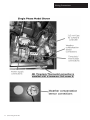
1
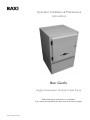
Operation Installation & Maintenance
Instructions
Baxi Geoflo
Single Compressor Compact Heat Pump
Please keep these instructions in a safe place.
If you move house, please hand them over to the next occupier
© Baxi Heating UK Ltd 2006
CONTENTS
Section
© Baxi Heating UK Ltd 2006 All rights reserved. No part of this publication may
be reproduced or transmitted in any form or by any means, or stored in any
retrieval system of any nature (including in any database), in each case whether
electronic, mechanical, recording or otherwise, without the prior written
permission of the copyright owner, except for permitted fair dealing under
Copyrights, Designs and Patents Act 1988.
Applications for the copyright owner’s permission to reproduce or make other
use of any part of this publication should be made, giving details of the proposed
use, to the following address:
The Company Secretary, Baxi Heating UK Ltd, Pentagon House,
Sir Frank Whittle Road, Derby, DE21 4XA.
Full acknowledgement of author and source must be given.
WARNING: Any person who does any unauthorised act in relation to a
copyright work may be liable to criminal prosecution and civil claims for damages.
2
© Baxi Heating UK Ltd 2006
Page
Compact Heat Pump Safety Information
3
Warranty Statement
4
Technical Data
5
Setting the Compact Heat Pump to work
6
Operating Instructions & Troubleshooting
7
Elevation of typical installation
8
Installation clearances
9
Hood removal clearances
10
Typical underfloor schematics
11
Ground plumbing illustration
12
Slinky® manifold connections
13
Plumbing connections
14
Output pump bleed port
15
Purge pumps
16
Purging the ground arrays
17
Typical Underfloor Wiring Connections
18
Control box layout
19
Wiring connections
20
Installation instructions
21
Installation instructions
22
Compact Heat Pump Safety Information
Installation
The appliance must be located well away from occupied spaces
to prevent the transmission of unwanted noise and vibration.
Locate the appliance in a separate room such as a utility room
or garage.
Take suitable precautions to prevent damage to the appliance
from frost.
Position the appliance on a firm, level and substantial concrete
base that will absorb vibration and that is not adjacent to any
occupied rooms.
Ensure all pipes and wires are adequately supported where
necessary, pipes are properly insulated and concentrations of
inhibitor are correct.
Do not place anything on the appliance.
Prior to use
Any electrical work required to install or maintain this appliance
should be carried out by a suitably qualified electrician in
accordance with current IEE regulations.
Any plumbing work should be carried out to local water
authority and WRC regulations.
The appliance should be left for 12 hours after installation
before it is turned on, in order to allow the refrigerant to settle.
The area must be dry.
This appliance is heavy. Care should be taken when moving it.
Check the appliance for transport damage. Under no
circumstances should a damaged appliance be operated or
installed.
It is dangerous to modify this appliance in any way.
Ensure that the appliance does not stand on the electrical
supply cable. If the supply cable is damaged , it must be
replaced.
Ensure that the appliance and any metal pipes are properly
earthed.
A water treatment device should be provided in hard water
areas.
Child Safety
Do not allow children to tamper with the controls or play with
the appliance.
Keep any packaging material away from children to prevent
danger of suffocation.
Ensure that animals are kept well away from the appliance.
Maintenance and cleaning
Before cleaning or performing maintenance, always switch off
the appliance at the electrical isolator.
Use only soap and a damp cloth; do not use solvents.
Operation
Always ensure that all individuals using the appliance have read
and fully understood the Operation instructions.
Do not operate the appliance with the cover removed or door
open .
Do not operate the appliance in anything other than very dry
conditions of installation.
Do not exert any strain on electrical or pipe connections to the
appliance.
Do not put any foreign object into the appliance.
Do not spill water or any other substance onto the appliance.
© Baxi Heating UK Ltd 2006
3
Warranty Statement
Baxi Geoflo Ground Source Heat Pumps
Thank you for purchasing a Baxi Geoflo Ground Source Heat Pump. This quality product has been developed to a high standard of specification and
should provide you with trouble free operation for many years to come. We are very confident you have made the right choice of product and
support it with a comprehensive free warranty.
Standard Warranty Terms and Conditions
Ground source heat pump - two years
Manifold
- two years
To receive your free warranty please complete the form supplied within 30 days of installation with the Geoflo system.
Our promise to you.
If you experience a fault with your new Geoflo system, we aim to provide a safe and high quality repair service supported by our dedicated national
network of highly skilled engineers. Together with your installer if you cannot resolve the problem, we will do everything we can to get an engineer out
to you as quickly as possible. Nothing in this warranty will affect your statutory consumer rights.
What you need to do if you experience a problem with your Geoflo system.
You should always contact your installer first because the fault may not be related to the Geoflo system. If your installer confirms that the fault is within
the Geoflo system itself and he/she decides they can't repair it our friendly customer service team is on hand to help.
Simply call our service division Heateam on 08700 603261 to book an engineer visit or for any general advice that you may need. Our contact centre is
open Monday to Friday 8am - 6pm, Saturday 8.30am – 2pm closed Sundays and Bank Holidays.
Before calling Heateam please have the following information to hand: Geoflo system serial number
Geoflo system model number
Your installer name, address details and contact details
Proof of purchase (if you do not have the Geoflo serial number)
What this warranty covers.
•
Free of charge repair or replacement of components found to be faulty from manufacture.
•
Free of charge replacement of the complete assemblies (excluding the ground array) provided always that the failure is related to a
manufacturing fault that cannot be repaired or is beyond repair.
•
The ground array (slinky) before backfilling trenches (a suitable pressure test must be carried out)
•
Warranty runs from the date your product is installed.
What this warranty does not cover.
•
Geoflo systems that are installed damaged or damaged during installation simply return it to the supplier for replacement under warranty.
4
•
The warranty will become invalid if the failure is due to frost, landslip, heave, subsidence, transient voltages, lightning strikes, rodent
damage or any act of vandalism, misuse or malicious conduct.
•
Tampering or modification will invalidate this warranty.
•
The installation must be in an appropriate location as detailed in the installation instructions.
•
Repairs to Geoflo system which have not been installed or commissioned properly and as set out in the installation instructions.
•
Any other defects or failures, either in the connected system or outside of the Geoflo system itself.
•
Faults caused by an inadequate supply of electricity to the property.
•
Reimbursement of any third party repair or replacement costs that we haven't been told about or agreed with you in advance.
•
Compensation for consequential losses (e.g. loss of earnings, business losses, stress and inconvenience) arising from a product breakdown,
including repair delays caused by factors outside our reasonable control.
© Baxi Heating UK Ltd 2006
Technical Data
© Baxi Heating UK Ltd 2006
5
Setting the Compact Heat Pump to work
Prior to use : 1. Turn off the power supply at the local isolator.
2. Open the door, using a screwdriver.
3. Check that the ground pressure gauge reads at least 0.3
bar. If the pressure is lower than this, open the mains cold
water supply valve (fitted outside the case) fully until the
gauge reads at least 1.8 bar, at which point a "click" will be
heard. Close the mains cold water supply valve fully. If you
can’t find this valve, or when you open it the gauge reading
does not increase, call your installer and ask them about
the mains cold water supply valve on the slinky® ground
array circuit.
4. Check that the underfloor pressure gauge reads at least
0.3 bar. If the pressure is lower than this, find the mains
cold water supply valve, which is probably near your
underfloor heating manifold fully until the gauge reads at
least 1.8 bar, at which point a "click" will be heard. Close
the mains cold water supply valve fully. If you can’t find this
valve, or when you open it the gauge reading does not
increase, call your installer and ask them about the mains
cold water supply valve on the underfloor circuit.
5. Close and re-lock the door.
6. Turn on the power supply at the local isolator and
program the external timeclock / thermostat to use as
much off-peak electricity as possible.
Maintenance Instructions
No routine maintenance is required to Compact Heat
Pumps, and there are no user-serviceable components
inside. If further help is required then telephone our
helpline on 08700 603 261
6
© Baxi Heating UK Ltd 2006
Operating Instructions & Trouble shooting
Prg
Sel
© Baxi Heating UK Ltd 2006
7
Elevation of typical installation
8
© Baxi Heating UK Ltd 2006
All dimensions in millimetrs
Recommended Installation Clearances
© Baxi Heating UK Ltd 2006
9
Hood Removal Clearances
All dimensions in millimetrs
10
© Baxi Heating UK Ltd 2006
© Baxi Heating UK Ltd 2006
11
12
© Baxi Heating UK Ltd 2006
Slinky® Manifold Connections
© Baxi Heating UK Ltd 2006
13
Pumbing Connections
14
© Baxi Heating UK Ltd 2006
Output Pump Bleed Port
© Baxi Heating UK Ltd 2006
15
Purge Pumps
It is possible that difficulty may be experienced removing air out
of the ground arrays, especially out of the top of each of the
“Slinky®” loops which consist of a large number of 1 metre
diameter loops of 1” bore pipe. This can also occur with vertical
(ie. drilled) arrays. All procedures for removing air from
slinkies® applies equally to removing air from underfloor
heating systems. Most underfloor heating manifolds have
fill/purge connections, and the same pump and procedure can
be used for underfloor as for slinkies®.
Why not just use mains water ?
A normal rising cold water main in a building has insufficient
flow to force out this air - typical flow rates from a cold tap are
around 10 to 30 litres per minute, which is less than half that
required. Also mains water is “aerated”.
Why can’t I use an existing pump that I have ?
To remove the air from Slinky® ground arrays, a suitable pump
will be required. The longest slinky® trench is 50 metres, which
will contain a total of about 300 metres of pipe. To achieve the
minimum velocity through the slinky® pipes to remove the air,
a minimum pump power in excess of 1 kW is required. If you
are considering using an existing pump and it does not absorb
at least 1 kW then it will not be suitable. In addition, the pump
needs to have high-flow (at least 60 litres per minute) against a
pressure of at least 1 bar. To achieve this, a “multi-stage” type
of pump is needed, which is different to “normal” types of
water pump.
Where can I get hold of a suitable purge pump ?
We recommend the Clarke CPE130SS, part no. 051010379
from www.machinemart.co.uk or telephone 0845 450 2855.
The pump comes ready to take a 1” BSP fitting. A plumbers
merchant can supply a 2 x 1” BSP male iron to 28 mm
compression. This will enable the pump to be connected to the
slinky® manifold using 28 mm “Speedfit” or similar pipe and
elbows.
Any other tips ?
Clarke CPE130SS
Purge Pump
16
© Baxi Heating UK Ltd 2006
Before it will work, the pump itself needs to be purged of air by
removing the fill plug, and filling with water, along with both
connecting pipes. Fill the ground arrays with water as far as
possible, and pressurise them with mains water using the coldfeed on the heat pump. Opening the valve between the slinky®
manifold and the water pump will force water through the
pump, into the dustbin, purging air out of the pump on the way.
It usually takes around 2 to 3 minutes of pumping for water to
go all the way through one slinky® and back to the dustbin. As
the Clarke CPE130SS will achieve up to 5 bar pressure against a
closed valve it is essential that the connections to the pump and
manifold are robust.
Purging the Ground Arrays
© Baxi Heating UK Ltd 2006
17
Underfloor Heating Wiring Connections
Single Manifold (smaller building)
Multiple Manifold (larger building)
18
© Baxi Heating UK Ltd 2006
Control Box Layout
© Baxi Heating UK Ltd 2006
19
Wiring Connections
20
© Baxi Heating UK Ltd 2006
Installation Instructions
Compact Heat Pump Installation Instructions
1. Decide on a suitable location for the Compact. The back of a domestic garage, or a utility room is recommended. It should not be placed in any inhabited
space. The Compact emits limited noise and vibration, and should not be placed adjacent to, or below bedrooms. Take into account the “Recommended
Clearances” when finalising the location.
2. Remove the door by turning the lock with a screwdriver, opening and lifting off.
3. Remove the hood by unscrewing the 5 mm hex key screws on either side of the base of the hood. Carefully lift the hood off, which may require two people.
4. Remove all three lower closure panels necessary to gain access to the pipe connections, by unscrewing the 4 x hex-headed stainless steel screws on each
panel.
5. Place the Compact in position and level it using the adjustable feet if necessary. Tighten the locking nuts on the feet when level.
6. Ensure the underfloor heating system has been thoroughly purged of any debris.
7. Using only plastic flexible pipe such as Speedfit® connect the cold feed, ground feed & return pipes from the Slinky® Manifold (which can be connected either
way round), feed & return pipes from the underfloor heating manifold (which must be connected the correct way round), according to the Plumbing
Connections Illustration. Flexible pipe must be used as the heat pump is suspended on anti-vibration mounts, so any connections must also be flexible.
8. Thread the power supply and timeclock/room thermostat wires from under the Compact into the control box and connect them to the terminals required
(see "wiring connections" illustration).
9. Fit the weather compensation sensor on a North facing wall, and connect with two-core minimum 0.5mm sq cable to the connections in the control box (see
"wiring connections" illustration). The wires can be connected either way round. Avoid routing this cable with any other cables to prevent interference.
10. Check and rectify any leaks that may be in the plumbing system.
11. Remove the plastic blanking plugs, and connect the purge pump to the fill and purge ports on the Slinky® Manifold (see "Purging the ground arrays"). Keep the
isolating valve to the heat pump closed. The purge ports can be connected either way round.
12. Connect the purge pump to suck from an 80 litre container (such as a dustbin) half filled with clean water. The pump must be capable of moving around 60
litres per minute against a pressure of approximately 1 bar. If the pump’s electrical rating is less than 1 kW, then it is unlikely to be suitable. The water level in the
container will need to be topped up constantly during the following process. The pump may need priming by pouring water into its priming port until it
overflows. Open the flow and return valves to one slinky®, and ensure that the others are closed, and the valve to the heat pump is also closed. Open the fill and
purge port valves (see "Purging the ground arrays").
13. Place a filter such as a kitchen sieve over the end of the pipe that returns water to the container so any debris will be captured. Start the purge pump, being
careful that the pipe returning water to the container does not splash or whip round and cause any injury.
14. Water should now be being pumped from the 80 litre container and into one of the slinkies®. If the water level in the container does not go down, then
pump priming should be repeated. No water should be flowing through the heat pump or through the other slinky®. The flow rate should be significant, usually in
excess of 30 litres per minute. This can easily be checked by holding a 10 litre bucket to collect water returning from the slinky®, and ensuring that it fills the
bucket in less than 20 seconds. If the flow is less than this sufficient velocity for the air in the tops of the slinkies® to be displaced is not being achieved. Purge each
slinky® for at least 10 minutes.
© Baxi Heating UK Ltd 2006
21
Installation Instructions (cont)
15. After water has circulated for approximately ten minutes, and no more debris has collected in the sieve, the valves on the first slinky® can be closed and the
valves opened on the other slinky®, again being careful that the return pipe into the container does not whip round and cause any injury. At this stage, the valve
to the heat pump should still be closed.
16. After another ten minutes, once no more debris has collected in the sieve, go on to any other slinkies® in turn. When all the slinkies® have been purged, the
valve to the heat pump can be opened, which will purge the heat pump of air - this is likely to occur very quickly, and great care should be taken that the hose
discharging into the container does not whip around.
17. Repeat the above procedure, placing the return hose from the slinky® manifold under water in the container until that there are no more bubbles of any
kind.
18. Once you are certain that you have circulated water around all the slinkies®, and there is no more air left in the entire ground array system or the heat
pump, pour antifreeze into the container (it may be necessary to remove some water first) and repeat the procedure, to ensure that all the antifreeze has mixed
thoroughly through to all the slinkies® and to the heat pump.
19. Close the fill and purge valves on the slinky® manifold with the pump running, shutting the return valve last so that the slinky® is left under pressure.
20. The system should remain pressurised at above 1 bar and can be checked for leaks; the pressure will slowly fall as the pipes in the ground arrays slowly
expand in the coming months, and may need topping up using the cold fill system provided. Most purge pumps will usually attain around 5 bar, and it is quite
acceptable to leave the circuit at this pressure, so that any leaks will immediately become apparent.
21. In order to activate the software controller, both the ground and underfloor circuits must be taken above 1.8 bar water pressure.
22. Remove the purging equipment, and the handles from the valves on the manifold to ensure they cannot be inadvertently operated, and place the plastic
blanking plugs back in the slinky® manifold.
23. Find the cold fill for the underfloor heating system and open the valve to allow water into the underfloor system and the Compact.
24. Remove the cap from the Output Pump Bleed Port and depress the schrader valve using a small screwdriver, as shown in the "Output pump bleed port"
illustration. Alternatively, the schrader valve core can be unscrewed completely using a car tyre valve core remover and a 10 mm internal diameter plastic pipe
placed on the outside of the valve to allow any water or air to be vented into a bucket.
25. When a solid stream of water comes from the valve the pump will be bled. This procedure needs to be repeated at intervals during the commissioning
procedure if there is any air in the underfloor system, which is highly likely. Place the cap back on the Output Bleed Valve .
26. Turn the power on to the heat pump. The display will read the temperature of the water returning from the underfloor / radiators. If error t1 is displayed,
then the heat pump will not run until both underfloor/radiator and ground circuits are at about 2 bar pressure.
27. Enable the heat pump, and make sure the impellors in both ground and underfloor/radiator water pumps are turning by removing the stainless steel screws
in the centre of each water pump and inserting a flat-bladed screwdriver.
28. Please call Baxi so that the Commissioning Sheet can be completed.
29. Replace the three closure panels by screwing in the 5 mm hex key screws on the front of the Compact. Carefully lift the hood back onto the Compact,
which may require two people. Screw in the 5 mm hex key screws on either side of the base of the hood. Replace the door and lock it shut.
22
© Baxi Heating UK Ltd 2006
Notes
© Baxi Heating UK Ltd 2006
23
All descriptions and illustrations provided in this leaflet have been carefully
prepared but we reserve the right to make changes and improvements in
our products which may affect the accuracy of the information contained in
this leaflet. All goods are sold subject to our standard Conditions of Sale
which are available on request.
Baxi Heating UK Ltd
Brooks House, Coventry Road, Warwick. CV34 4LL
After Sales Service and Technical Enquiries 08700 603 261
Website www.baxi.co.uk
e&oe
company
© Baxi Heating UK Ltd 2006
Comp No TP0201 - Iss 2 - 7/06