1
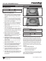
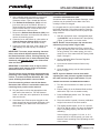
Manufacturing
Numbers:
910 0 9 2 2
Steamer/Scale
C
L IS
T ED
US
AN
Model STS-200
I T A T IO
L IS
N
S
T ED
CM
P/N 1010929 Rev. B 03/12
Owner ’s Manual
STS-200 Steamer/Scale
Table of contents
Owner Information......................................................2
General.......................................................................2
Warranty Information..................................................2
Service/Technical Assistance.....................................3
Important Safety Information.....................................3
Specifications .............................................................5
Dimensions.................................................................5
Electrical Ratings........................................................5
Electrical Cord & Plug Configurations........................5
Installation....................................................................6
Unpacking...................................................................6
Equipment Setup........................................................6
Operation......................................................................7
Operating Instructions................................................7
Calibrating the Steamer/Scale....................................7
Rotary Switch Settings...............................................8
Maintenance.................................................................9
Cleaning the STS-200 During Daily Use....................9
Daily Maintenance....................................................10
Weekly Maintenance................................................10
Monthly Maintenance...............................................12
Troubleshooting........................................................13
Message Codes........................................................13
Error Codes..............................................................13
Technical Theory of Operation................................17
Technical Theory of Operation.................................17
Replacement Parts....................................................19
Wiring Diagram..........................................................27
Limited Warranty.......................................................28
Owner Information
General
Warranty Information
The STS-200 Steamer/Scale produces steam using
plain tap water for quick steaming of sliced meats.
Simple push-button action delivers a consistent impulse
of steam. Because the amount of steam is consistent, it
removes the guesswork and produces a uniform
finished product from one operator to the next.
Please read the full text of the Limited Warranty in this
manual.
If the unit arrives damaged, contact the carrier immediately and file a damage claim with them. Save all
packing materials when filing a claim. Freight damage
claims are the responsibility of the purchaser and are
NOT covered under warranty.
This manual provides the safety, installation, and operating procedures for the Steamer/Scale. We recommend that all information contained in this manual be
read prior to installing and operating the unit.
The warranty does NOT extend to:
Your Steamer/Scale is manufactured from the finest
materials available and is assembled to Roundup’s
strict quality standards. This unit has been tested at the
factory to ensure dependable trouble-free operation.
• Damages caused in shipment or damage as
result of improper use.
• Installation of electrical service.
• Normal maintenance as outlined in this manual.
• Malfunction resulting from improper maintenance.
• Damage caused by abuse or careless handling.
• Moisture damage to electrical components.
• Damage from tampering with, removal of, or
changing any preset control or safety device.
Important! Keep these instructions for future reference. If the unit changes
ownership, be sure this manual accompanies the equipment.
2
A.J. Antunes & Co.
P/N 1010929 Rev. B 03/12
STS-200 Steamer/Scale
Owner information (continued)
Service/Technical Assistance
Refer to the service agency directory and fill in the
information below:
If you experience any problems with the installation
or operation of your unit, contact your local Roundup
Authorized Service Agency. They can be found in the
service agency directory packaged with the equipment.
Authorized Service Agency
Name:
Phone No.:
Fill in the information below and have it handy when
calling your Authorized Service Agency for assistance.
The serial number is on the specification plate located
on the rear of the unit.
Address:
Use only genuine Roundup replacement parts in this
unit. Use of replacement parts other than those supplied by the manufacturer will void the warranty. Your
Authorized Service Agency has been factory trained
and has a complete supply of parts for this unit.
Purchased From:
Date of Purchase:
Model No.:
You may also contact the factory at 1-877-392-7854 or
1-630-784-1000 if you have trouble locating your local
Authorized Service Agency.
Serial No.:
Mfg. No.:
Important Safety Information
Throughout this manual, you will find the following safety words and symbols that signify important safety issues with
regards to operating or maintaining the steamer.
Warning
Warning
GENERAL WARNING. Indicates information important to the proper operation of
the equipment. Failure to observe may
result in damage to the equipment and/or
severe bodily injury or death.
ELECTRICAL WARNING. Indicates information relating to possible shock hazard.
Failure to observe may result in damage
to the equipment and/or severe bodily
injury or death.
Caution
Warning
GENERAL CAUTION. Indicates information important to the proper operation of
the equipment. Failure to observe may
result in damage to the equipment.
P/N 1010929 Rev. B 03/12
HOT SURFACE WARNING. Indicates
information important to the handling of
equipment and parts. Failure to observe
caution could result in personal injury.
3
A.J. Antunes & Co.
STS-200 Steamer/Scale
Important safety information (continued)
- Do NOT use an extension cord with this
appliance.
In addition to the warnings and cautions in this manual,
use the following guidelines for safe operation of the
unit.
• Read all instructions before using equipment.
• For your safety, the equipment is furnished with
a properly grounded cord connector. Do NOT
attempt to defeat the grounded connector.
-Check with a qualified electrician if you are
unsure if the appliance is properly grounded.
• Install or locate the equipment only for its intended
use as described in this manual. Do NOT use
corrosive chemicals in this equipment.
• This equipment is to be installed to comply
with the basic plumbing code of the Building
Officials and Code Administrators, Inc. (BOCA)
and the Food Service Sanitation Manual of the
Food and Drug Administration (FDA).
• Do NOT operate this equipment if it has a damaged
cord or plug, if it is not working properly, or if it
has been damaged or dropped.
• If the supply cord is damaged, it must be
replaced by the manufacturer or its service
agent, or a similarly qualified person.
• Do NOT clean this appliance with a water jet.
• Do NOT use a sanitizing solution or abrasive
materials. The use of these may cause damage
to the stainless steel finish.
• To ensure proper steaming characteristics,
some mineral deposits must be present on
generator surface. If, during cleaning, the
surface does become free of mineral deposits, one approved method is to add plain tap
water to the generator surface and allow it
to boil off. This will ensure proper steaming
characteristics by creating a thin layer of mineral deposits on the casting.
• Chlorides or phosphates in cleaning agents
(e.g. bleach, sanitizers, degreasers or detergents) could cause permanent damage to
stainless steel equipment. The damage is
usually in the form of discoloration, dulling
of metal surface finish, pits, voids, holes or
cracks. This damage is permanent and NOT
covered by warranty.
• This equipment should be serviced by qualified
personnel only. Contact the nearest Roundup
Authorized Service Agency for adjustment or
repair.
• Do NOT block or cover any openings on the unit.
• Do NOT immerse cord or plug in water.
• Keep cord away from heated surfaces.
• Do NOT allow cord to hang over edge of table or
counter.
The following warnings and cautions appear
throughout this manual and should be carefully
observed.
• Turn the power off, unplug the power cord,
and allow unit to cool down before performing
any service or maintenance.
• The equipment should be grounded according to local electrical codes to prevent the
possibility of electrical shock. It requires a
grounded receptacle with separate electrical
lines, protected by fuses or circuit breaker of
the proper rating.
• All electrical connections must be in accordance with local electrical codes and any
other applicable codes.
• Warning electrical shock hazard.
Failure to follow these instructions
could result in serious injury or
death.
•
- Always use soft, damp cloth for cleaning,
rinse with clear water and wipe dry. When
required, always rub in direction of metal
polish lines.
-Routine cleaning should be done daily
using soap and water.
-Stains and spots should be removed using
a vinegar solution as required.
-Electrical ground is required on this unit.
-Finger marks and smears should be
removed using soap and water.
- Do NOT modify the power supply cord plug.
If it does not fit the outlet, have a proper outlet installed by a qualified electrician.
- Hard water spots should be removed using
a vinegar solution.
4
A.J. Antunes & Co.
The following tips are recommended for maintenance of your stainless steel equipment:
P/N 1010929 Rev. B 03/12
STS-200 Steamer/Scale
Specifications
Dimensions
Electrical Ratings
8 1/2"
(216 mm)
13 1/2"
(33 mm)
7 1/4"
(184 mm)
Model &
Mfg. No
Voltage
Watts
Amps
Hertz
STS-200
9100922
120
1500
12.5
50/60
Electrical Cord & Plug Configurations
11 1/4"
(286 mm)
Warning
ELECTRICAL SHOCK HAZARD.
Model &
Mfg. No.
Description
STS-200
9100922
NEMA 5-15P,
15 Amp., 120 VAC.,
Non – Locking.
Configuration
GRN
WHT
BLK
Caution
This equipment is to be installed to comply with
the basic plumbing code of the Building Officials
and Code Administrators, Inc. (BOCA) and the
Food Service Sanitation Manual of the Food and
Drug Administration (FDA).
Failure to follow the instructions in
this manual could result in serious
injury or death.
• Electrical ground is required on this appliance.
Caution
• Do NOT modify the power cord plug. If it does
not fit the outlet, have a proper outlet installed
by a qualified electrician.
Handle the Steamer/Scale with care. Do NOT place
objects other than sliced meat on the unit and
NEVER place anything over 4 pounds (64 ounces)
on the Steamer/Scale.
• Do NOT use an extension cord with this
appliance.
Caution
All electrical connections must be in accordance
with local electrical codes and any other applicable codes.
• Check with a qualified electrician if you are
unsure if the appliance is properly grounded.
Caution
The Steamer/Scale uses a direct water line. Water
pressure coming into the unit must be set to 7–9
psi using a Water Pressure Regulator.
P/N 1010929 Rev. B 03/12
5
A.J. Antunes & Co.
STS-200 Steamer/Scale
Unpacking
Installation
5. Plug the power cord into the appropriate outlet.
6. Note that the Rotary Switches on the back of the
unit (Figure 2) are pre-set to
•
Temp Rotor Switch - 0
•
Cycle Rotor Switch - 4
•
Shot Rotor Switch - 4
1. Remove unit and all packing materials from shipping carton.
2. Open the carton. It should contain the following:
• STS-200 Steamer/Scale
• Water Pressure Regulator Kit
• Owner’s Manual and Maintenance Sheet
• 16-Ounce Calibration Weight
• Stainless Steel Cleaning Brush
Top
Cover
NOTE: If any parts are missing or damaged, contact Antunes Technical Service IMMEDIATELY at
1-877-392-7854 or 1-630-784-1000.
Storage Shelf for
Calibration Weight
and Cleaning Brush
Diffuser
3. Remove all packing materials and protective
coverings from the unit.
Water
Inlet Tube
Steam
Generator
4. Remove all removable parts and wipe them with
a clean towel dampened with sanitizer. Allow
them to air dry.
5. Wipe all surfaces of the unit with a clean towel
dampened with sanitizer and allow to air dry.
Locating the
Hidden Button
Ready
Light
ZERO
(on)
6. Re-install all removed parts and verify that all
parts are present.
3/4"
Hidden
button
Equipment Setup
Zero (on)
button
General
Neg
Digital
Oz LED
Air Bulb Display
LED
Switch
with
NOTE: The Power Switch is
Tubing
located on the back of unit.
The STS-200 Steamer/Scale is used to heat and portion
sliced meats. The Air Bulb Switch initiates a shot of
steam while the digital display shows the weight of the
sliced meat (Figure 1).
Steamer/Scale Setup
Figure 1. STS-200 Steamer/Scale
When placing the Steamer/Scale into service, pay
attention to the following guidelines:
• Do NOT block or cover any openings on the units.
• Do NOT immerse cords or plugs in water.
• Keep cords away from heated surfaces.
• Do NOT allow cords to hang over edge of table or
counter.
Temp Rotary
Switch
Cycle Rotary
Switch
Shot Rotary
Switch
Yellow
Heater
Led
Water Inlet
Connection
3. Connect the outlet hose/fitting from the Dual
Water Regulator Kit to the Water Inlet Connection
at the rear of the unit (Figure 2).
Power
Cord
4.Connect the Air Bulb Switch tubing to the Air
Hose Connection on the back of the unit (Figure
2). Push the tubing onto the connector. See the
instructions for optional mountings.
Green
Solenoid Led
Rocker Switch
(with Power LED)
Air Hose
Connection
Figure 2. STS-200 Steamer/Scale (Back View)
Without Storage Shelf Shown for Better View.
6
A.J. Antunes & Co.
P/N 1010929 Rev. B 03/12
STS-200 Steamer/Scale
Operation
6. When the Blue LED turns on, another steam/time
cycle can be initiated.
Caution
Handle the Steamer/Scale with great care. Do not
place objects other than sliced meat on the unit
and NEVER place anything over 4 pounds (64
ounces) on the Steamer/Scale. Damage to the unit
may result due to careless handling or misuse.
7. Remove steamed product and complete the
assembly of the sandwich.
Calibrating the Steamer/Scale
If the Steamer/Scale displays anything other than “0.0”
during operation, first zero the scale. If the Steamer/
Scale still does not display “0.0” after it has been
zeroed, you must calibrate it as follows:.
Important
Handle the Top Cover with care. If the Top Cover
is bent, dented, or damaged, it may not sit properly on the Steamer/Scale resulting in inaccurate
weight measurements.
1.Turn the power on and allow the unit to warm up
for 30 minutes.
Operating Instructions
2.Turn the unit off and wait for 20 seconds.
1.Turn the power on and allow the unit to preheat
for approximately 30 minutes. The Yellow LED
located on the back of the unit will illuminate during
the time that the heating element is heating up.
3.Ensure nothing is on the Steamer/Scale surface
and that the Top Cover is seated correctly.
4. Directly to the right of the Zero (on) button is the
Hidden button used to adjust the scale (Figure 1).
Simultaneously press and hold both the Zero button
and the Hidden button and then turn the unit on.
2. When the unit is ready for operation, the Blue
LED on the front of the unit will turn on and
remain lit. The unit will display 0.0. If it displays
anything besides “0.0”, zero the scale by pressing the Zero (on) button once. If the display still
does not read “0.0”, perform the procedures in
the Calibrating the Steamer Scale section of this
manual.
5.Continue holding the buttons. The system displays
“888”, “93”, “r 1.8”, and then “rb”. At this point,
release both buttons. The unit will then display
“C0”. If the unit does not display “C0”, repeats
Steps 2 through 5.
NOTE: Do NOT press any buttons or use the scale
until it has warmed up and the Blue LED is on.
5. Press and release the Zero (on) button and wait
for 10 seconds. Do NOT bump the unit, counter,
or touch “the” Steamer/Scale during this 10-second period! The unit will then display “C” and
then “C1”.
3. Place the sliced meat onto the center of the
Steamer/Scale surface. At the same time, press
the Air Switch (Figure 1). The Steamer/Scale will
initiate a shot of steam.
6. Place the 1-pound (16 oz.) calibration weight
on the center of the scale surface. Press and
release the Zero (on) button. Wait 10 seconds.
Do NOT bump the unit, counter, or touch the
Steamer/Scale during this 10 seconds. During
this 10 second time frame, the unit will display “C”,
“don”, “Sav”, and then “15.9”, “16.0”, or “16.1”.
4. The Blue LED will also turn off for 4 seconds. This is the timer cycle.
5. Note the weight of the sliced meat and adjust
according to serving requirements.
Important
Weight readings are accurate at the center of the
scale surface ONLY. Do not weigh sliced meat on
the edges or corners of the Steamer/Scale.
P/N 1010929 Rev. B 03/12
7. Remove the 1-pound (16 oz.) calibration weight.
8.The unit should read “0.0”. If it does not, repeat
Steps 2 though 7.
7
A.J. Antunes & Co.
STS-200 Steamer/Scale
Operation (continued)
Rotary Switch Settings
At the back of the STS-200 unit are three Rotary
Switches: Temp, Cycle, and Shot.
7
6
6
9
5
5
4
1
4
Temp.
Cycle/sec
Shot/Sec
0
375°F*
10.0
1.0
9
370°F
9.0
0.9
8
365°F
8.0
0.8
7
360°F
7.0
0.7
6
355°F
6.0
0.6
5
350°F
5.0
0.5
4
345°F
4.0*
0.4*
3
340°F
3.0
0.3
2
355°F
2.0
0.2
1
330°F
1.0
0.1
0
1
3
1
2
6
8
0
0
5
7
9
9
4
8
3
8
2
7
Setting
2
3
TEMP CYCLE SHOT
SOL HTR
The Temp Rotary Switch sets the operating temperature
of the unit. The Cycle Rotary Switch sets the length of
a steam cycle in seconds. The Shot Rotary Switch sets
the amount of water used in each cycle of operation.
The standard settings and other possible settings are
listed in the following table.
* These are the Standard Settings for the STS-200.
8
A.J. Antunes & Co.
P/N 1010929 Rev. B 03/12
STS-200 Steamer/Scale
Maintenance
Precaution:
During these checks, hot surfaces will be exposed.
Hazard Communication Standard (HCS) – The procedures on this card include the use of
chemical products. These chemical products will be highlighted with bold face letters followed by the abbreviation (HCS) in the tools portion of the procedure. See the Hazard
Communication Standard (HCS) Manual for the appropriate Material Safety Data Sheet(s) (MSDS).
Warning
Turn the power off, unplug the power cord, and allow
the unit to cool down before performing any service or
maintenance.
Cover
Diffuser
IMPORTANT
Read ALL instructions on the cleaning products used.
Follow all instructions regarding the proper cleaning
product to use as well as the proper mixture and/or
handling of the cleaning product.
Steam
Generator
Caution
Steamer/
Scale
Chlorides or phosphates in cleaning agents (such as
bleach, sanitizers, degreasers, or detergents) could
cause permanent damage to stainless steel equipment.
The damage is usually in the form of discoloration,
dulling of metal surface finish, pits, voids, holes, or
cracks. This damage is permanent and not covered by
warranty.
Figure 3. Steamer/Scale Components
Cleaning the STS-200 During Daily Use
Caution
The Top Cover, Diffuser, and Steam Generator are HOT
when performing the following procedures.
The table below describes the types of cleaners and
detergents used during maintenance of the Steamer/
Scale.
During the day’s use, there is a build up of meat and
meat juices on the Top Cover, Diffuser, and in the
Steam Generator.
You MUST use the appropriate cleaner for the task
based on the appropriate supplier.
Proctor & Gamble
Product Name
Damon
Product Name
General
Detergent
Cleaner (HCS)
Dawn™ Detergent
Solution
Lark® Detergent
Solution
Steam
Generator
Cleaner (HCS)
Spic and Span® Multisurface Cleaner (the
Green Liquid)
SF-77®
Degreaser
Detergent.
Delimer/Scale
Remover
(HCS)
DCT-Delimer Solution
Sanitizer
Solution (HCS)
Clean Quick Sanitizer
P/N 1010929 Rev. B 03/12
Hidden
button
Zero (on)
button
The frequency of cleaning is determined by water conditions, usage and water filter systems.
Document
Term
Water Inlet
Tube
This should be cleaned throughout the day. To do so,
remove the Top Cover and Diffuser and clean them with
a damp cloth (not dripping).
Using the damp cloth, wipe out the Steam Generator to
remove any meat and/or juices.
If the Water Inlet Tube becomes clogged so that water
cannot flow onto the Steam Generator, refer to the
Cleaning The Water Inlet Tube section in this document.
--Ster-O-Kem® #15
Sanitizer
9
A.J. Antunes & Co.
STS-200 Steamer/Scale
Maintenance (continued)
Daily Maintenance
IMPORTANT
Turn off the power, unplug the power cord, and allow
the unit to cool down before proceeding.
Cleaning the Steamer Scale
1. Check the Water Quick Disconnect Fitting and all
hose clamp connections for leakage. If leakage
is apparent, tighten all clamps or replace part if
required.
Figure 4. Dirty Steam Generator
2. Remove the Top Cover and Diffuser and wash in
a solution of Steam Generator Cleaner (HCS).
3. Use a wire brush to clean/remove the meat residue
from the Top Cover and Diffuser.
4. Rinse the Top Cover and Diffuser with clear water.
5. Rinse the Top Cover and Diffuser in Sanitizer
Solution (HCS) and then again with clear water.
Allow to air dry.
Figure 5. Clean Steam Generator
6.Clean the Steam Generator by wiping off any
meat and meat juices. Weekly Maintenance
7. Pour some Steam Generator Cleaner (HCS) into
the Steam Generator. Wait 15 minutes and then
use the wire brush to clean the Steam Generator
by removing all meat and meat juices.
IMPORTANT
Turn off the power, unplug the power cord, and allow
the unit to cool down before proceeding.
8. Rinse the Steam Generator with clear water.
9. Rinse the Steam Generator using Sanitizer
Solution (HCS) and then again with clear water.
Repeat this step as needed until the Steam
Generator is cleaned.
Caution
Observe all instructions, precautions, and warnings on
cleaning product labels.
The STS-200 Steamer/Scale utilizes an open Steam
Generator. Water sprayed into the Steam Generator
surface flashes into steam immediately, but the minerals in the water do not steam. They stay on the Steam
Generator surface and accumulate. A small amount of
mineral deposits are needed for proper operation, but
a build-up of excessive mineral deposits causes poor
steaming efficiency, excessive moisture (wet steam)
and will eventually severely retard the steaming action
completely.
10. In this step, the cloths are to be damp, NOT
dripping wet. Clean the Steamer Scale base
using a damp soft cloth and General Detergent
Cleaner (HCS).
11. Rinse the Steamer Scale base with a soft cloth
dampened with clear water.
12. Rinse the Steamer Scale base using a soft cloth
dampened with Sanitizer Solution (HCS) and
then a soft cloth dampened with clear water.
13. Re-install the Diffuser and Top Cover and plug the
power cord into the appropriate outlet.
Cleaning Steam Generator
1. Perform the Daily Maintenance first.
14.Turn the Steamer/Scale on, allow the unit to
preheat for 30 minutes, and zero it by pressing Zero
(on) button on the front of the unit (Figure 3).
2. Remove the Top Cover from unit.
3. Remove the Steam Diffuser.
15. If the Water Inlet Tube becomes clogged so that
water cannot flow onto the Steam Generator, refer
to the Cleaning The Water Inlet Tube section in
this document.
4.Clean Steam Generator free of any product spills.
NOTE: If the mineral deposits come off in flakes or
layers, build-up is excessive.
10
A.J. Antunes & Co.
P/N 1010929 Rev. B 03/12
STS-200 Steamer/Scale
Maintenance (continued)
5.Use a stainless steel wire brush to loosen and
remove excessive deposits from the Steam
Generator surface. Then, reinstall the Diffuser.
Cleaning the Water Inlet Tube
Sometimes when cleaning the Steam Generator, small
particles may be pushed into the Water Inlet Tube,
causing it to become clogged.
6.Pour Delimer/Scale Remover (HCS) so that it
just covers the top of the Diffuser. Be sure to
follow the delimer manufacturer’s directions for
proper mixture and use; it must be safe to be
used on aluminum. Wait one hour.
In a clogged state, the unit is unable to spray water into
the Steam Generator. Follow these steps to clean the
Water Inlet Tube and to restore the unit to proper operating condition:
7. Remove the Delimer/Scale Remover (HCS) from
the Steam Generator and rinse with clear water to
remove all remaining traces.
1. With the unit heated, insert a straightened paper
clip SLIGHTLY into the Water Inlet Tube opening
(Figure 1) and rotate in a circular motion.
8. Clean the Cover and Diffuser in a hot solution of
General Detergent Cleaner (HCS) and water,
then rinse in clear water and allow to air dry.
NOTE: Do NOT shove the paper clip into the tube,
otherwise you may further clog the tube.
9.Clean unit surface with a hot, clean, damp cloth
(not dripping wet) and wipe dry. Re-install all
parts.
2.After cleaning the Water Inlet Tube, remove the
paper clip and cycle the unit several times to flush
out any particles. If the water sprays, the unit is
ready for use. If the water does NOT spray, follow
Steps 3 through 5.
IMPORTANT: To ensure proper steaming characteristics, some mineral deposits must be present on
the Steam Generator surface. If during cleaning, the
surface does become free of mineral deposits (bare
aluminum), add plain tap water to the surface and
allow it to boil off.
3.Set the adjustable Water Pressure Regulator
between 20–25 psi.
4.Cycle the unit several times to flush out any
particles.
IMPORTANT: In soft water areas, it may be necessary to add a small amount of lime to the Steam
Generator surface to “season” it.
5. Once the water sprays, set the water pressure
back to 7–9 psi.
This will ensure proper steaming characteristics by
producing a thin coating of mineral deposits on the
surface. To season the Steam Generator, Mix 1 teaspoon of Baking Soda with 3 ounces of water.
NOTE: Cycle the Steamer several times while
adjusting the water pressure regulator knob until
the water pressure gauge reads between 7–9 psi.
Testing the STS-200 for Weighing Accuracy
Pour the seasoning mixture onto the hot Steam
Generator. After mixture is converted to steam, the
remaining loose powder can be removed.
1.Turn the unit on and allow it to warm up for 30
minutes.
10. Plug the power cord into the appropriate outlet
and connect the water line. Turn the Steamer/
Scale on, allow the unit to preheat for 30 minutes,
and zero the unit.
2.Ensure nothing is on the Steamer/Scale surface
and that the Top Cover is seated correctly.
11.If the Water Inlet Tube becomes clogged so that
water cannot flow onto the Steam Generator, refer
to the Cleaning The Water Inlet Tube section of
this manual.
4. Place the certified 1-pound (16 ounce) calibration
weight in the center of the scale surface.
3. Press the Zero (on) button once. The display
should now read “0.0”.
5.The display should register 15.9 to 16.1 ounces
(452.67 to 458.36 grams). If it does, the Steamer/
Scale is weighing properly, and does not need
calibrating.
If the unit does not register 15.9, 16.0, or 16.1
ounces (452.67 to 458.36 grams), you must calibrate the scale according to the Operating section
of this manual.
P/N 1010929 Rev. B 03/12
11
A.J. Antunes & Co.
STS-200 Steamer/Scale
Maintenance (continued)
Monthly Maintenance
Checking/cleaning the water strainer
The Water Strainer protects the unit from any foreign
debris in the water line that could get into the food,
damage the unit’s solenoid (causing the unit to leak or
flood), or interfere with the equipment’s proper and
consistent operation.
To ensure proper and consistent steaming results,
check the Water Pressure Regulator and Strainer Cup
regularly. If the pressure on the gauge has dropped,
check the Strainer Cup and clean out the accumulated
debris as follows.
1.Remove the Quick Disconnect #2 from the incoming
water supply or shut off the water supply valve to
the unit. Unscrew the Strainer Cup and carefully
remove the Mesh Strainer Screen.
2.Take the Strainer Cup and Mesh Strainer to the
sink and gently flush all the accumulated debris
out of them, be especially careful not to damage
the Mesh Strainer Screen.
3.Carefully place the Mesh Strainer Screen into its
seat at the bottom of the Stainer Cup and verify
that the orange O-ring is properly seated in its
place before screwing the Strainer Cup and top
back together.
4. Reinstall the quick disconnect until it clicks into
place.
5. Purge the air out of the strainer by cycling the unit
through several steam cycles.
6. Replace damaged or worn parts as needed.
NOTE: Refer to the Replacement Parts section of
this manual for a complete list of parts.
12
A.J. Antunes & Co.
P/N 1010929 Rev. B 03/12
STS-200 Steamer/Scale
Troubleshooting
Message Codes
The table below lists the possible message codes displayed by the unit during operation. Contact the factory if you
have any questions about these message codes.
Message
Code
Description
888
Display test, all digits on.
93
Software part number, DSW0093.
r0.3
Software revision.
Ld0
Loading zero, shown on start up.
don
Indicates that calibration is complete.
SAv
Indicates that the current values are saved into memory.
Unt
Display Units (toggles between ounces or grams).
Int
Initialize or reset all scale settings in memory.
r b
Release button. Prompts user to release the Zero (On) or hidden buttons.
Error Codes
The table below lists the possible error codes displayed by the unit when an error occurs.
NOTE: If any of these errors appear on the Steamer/Scale display, contact the factory.
Error Code
Description and Corrective Action
“E1” Program
Rom Error
The program memory in the Steamer/Scale has become corrupted. Have the Steamer/Scale serviced by a qualified Scale Repair Technician.
“E2” Gross
Overload
The Steamer/Scale is in gross overload. The load exceeds the scale’s input range and might
result in damage to the Load Cell. Remove excess weight immediately or Load Cell connections
may be wired in wrong. Ignore this message for the first 5 seconds after powering the Steamer/
Scale.
“E3” Scale
Overload
The Steamer/Scale is in overload. The load on the scale exceeds capacity by more than 103%.
Remove excess weight from the Steamer/Scale.
“E4” Calibration The Calibration Span is out of range, refer to A/D Ranging section for additional information.
Span Error
“E5” EEPROM
Error
The setup parameters loaded in nonvolatile memory have been corrupted. The Have the
Steamer/Scale re calibrated by a qualified Steamer/Scale Technician.
“E6” Calibration The “zero” Calibration is out of range. Refer to the A/D Ranging section for additional information.
Range Error
“E7 A/D Failure The scale has detected a failure in A/D circuit. Have the Steamer/Scale serviced by a qualified
Steamer/Scale Repair Technician.
P/N 1010929 Rev. B 03/12
13
A.J. Antunes & Co.
STS-200 Steamer/Scale
Troubleshooting (continued)
Problem
The unit heats up and steams but
the front display is blank.
Possible Cause(s)
Faulty scale Control Board.
Faulty temperature Control Board.
Disconnected/Loose wiring harness.
Unit operates, but the front display
intermittently goes blank then
comes back on after several minutes.
Corrective Action
Contact your maintenance person
or an Authorized Service Agency for
service.
The automatic resetting hi-limit is trip- Contact your maintenance person
ping due to the generator overheating. or an Authorized Service Agency for
service.
Faulty temperature Control board.
Faulty thermistor.
NOTE: The generator surface
temperature is in excess of
375°F. The hi-limit will trip at
450-470°F.
No heat, the front display is blank,
and the light on the power switch
is off.
Power cord not plugged into the
appropriate outlet.
Verify that the power cord is plugged
into the appropriate outlet.
Circuit breaker is off or tripped.
Verify circuit breaker is on.
Faulty power cord.
Contact your maintenance person
or an Authorized Service Agency for
service.
Faulty terminal block.
Faulty power switch.
No heat, the front display is on,
and the Blue LED is on steady.
Thermistor is shorted.
Blue LED flashes rapidly.
Thermistor is open.
Faulty temperature Control Board.
Contact your maintenance person
or an Authorized Service Agency for
service.
Contact your maintenance person
Loose, burnt, or broken wiring in heat- or an Authorized Service Agency for
service.
ing circuit.
One of the two generator heaters is
open.
Faulty temperature Control Board.
No heat, front display is blank, but
the light on the power switch is
ON.
Faulty transformer.
Faulty temperature Control Board.
Loose or broken wiring in circuit.
The Blue LED repeatedly flashes 1 Insufficient ventilation around unit.
second on 3 seconds off
Faulty Temperature Control Board
NOTE: The electrical compartment temperature has exceeded
155°F.
The Blue LED intermittently flashes
1 second on 1 second off during
normal use.
NOTE: The generator surface
temperature has dropped below
280°F. Proper operating temperature is 375°F.
Turn unit off and let cool down. If
the problem persists, contact your
maintenance person or an Authorized
Service Agency for service.
Water pressure regulator is improperly Adjust regulator to 7-9 PSI.
set.
Rotary switches are not correctly set
Set switches to the proper settings
shown under the “Equipment Setup”
section in the manual.
One of the two generator heaters is
open
Contact your maintenance person
or an Authorized Service Agency for
service.
Faulty Temperature Control Board.
14
A.J. Antunes & Co.
Contact your maintenance person
or an Authorized Service Agency for
service.
P/N 1010929 Rev. B 03/12
STS-200 Steamer/Scale
Troubleshooting (continued)
Problem
Scale is not weighing properly and/or behaves
erratically.
Unit heats, does not steam,
but the Green LED at the
rear of the unit DOES turn
on for a split second as the
air bulb is pressed.
Possible Cause(s)
Corrective Action
Scale requires calibration.
Calibrate scale according section titled
“Calibrating the Steamer Scale” in the
Operation section of this manual.
Interference/binding with the floating
“Spider” (refer to part number 0504087 on
page 21 in the Replacement Parts section
of this manual.)
If unit was recently disassembled and/or
serviced, some possible wiring or component may be interfering / binding with
the floating spider.
Faulty load cell.
Contact your maintenance person or an
Authorized Service Agency for service.
Faulty scale Control Board.
Contact your maintenance person or an
Authorized Service Agency for service.
The water valve is in the OFF position.
Verify water valve is ON.
The quick disconnect fitting is not fully
inserted into the inlet side of the Water
Pressure Regulator.
Remove and reinsert the quick disconnect fitting until a “click” is heard.
The quick disconnect fitting is not fully
inserted into the rear of the scale/steamer.
The water regulator strainer screen is
clogged.
Clean the strainer according to the
Maintenance section of this manual.
The generator’s water inlet tube is clogged. Clean the inlet tube according to the
Maintenance section of this manual.
Unit heats, does not steam,
but the Green LED at the
rear of the unit DOES NOT
turn on for a split second
as the air bulb is pressed.
P/N 1010929 Rev. B 03/12
Faulty solenoid valve.
Contact your maintenance person or an
Authorized Service Agency for service.
Air Bulb Hose is not properly connected to
the rear of the unit.
Remove and reattach the Air Bulb
Hose.
Air Bulb Hose is damaged.
Replace Air Bulb or hose if damage is
apparent.
Air Bulb is damaged.
Faulty Air Bulb Switch.
Contact your maintenance person or an
Authorized Service Agency for service.
15
A.J. Antunes & Co.
STS-200 Steamer/Scale
Troubleshooting (continued)
Problem
Possible Cause(s)
Corrective Action
The unit is not
steaming the product
properly and/or the
product requires
re-steaming.
The Water Pressure Regulator is improperly set.
Adjust regulator to 7-9 PSI. Refer to the section titled “Adjusting the Water Pressure
Regulator” in this manual.
The water regulator strainer screen is
clogged.
Clean the strainer according to the
Maintenance section of this manual.
Rotary switches are not correctly set.
Set switches to the proper settings shown in
the “Equipment Setup” section of this manual.
The generator water inlet tube is clogged. Clean the inlet tube according to the
Maintenance section of this manual.
The generator needs cleaning.
Clean the generator according to the
Maintenance section of this manual.
The unit is not being cleaned as required. Clean the unit according to the Daily, Weekly,
& Monthly cleaning procedures found in the
Maintenance section of this manual.
The generator surface is not hot enough.
Preheat the unit and verify that the generator
surface temperature is at least 375° F.
The generator surface The solenoid valve is leaking due to
Attempt to flush the debris out by increasing
continuously fills with debris trapped within its plunger and seat. the water regulator to 30 PSI & cycling the
unit several times. Reset the regulator back to
water ONLY when the
7-9 PSI. If the problem persists. Contact the
power switch is OFF.
Authorized Service Agency for service
The Solenoid Valve is not installed
correctly.
If the Solenoid Valve was replaced, verify that
the “IN” and “OUT” labels on the valve correspond to the water flow.
The generator surface Faulty temperature Control Board
continuously fills with
water ONLY when the
power switch is turned
ON.
Contact your maintenance person or an
Authorized Service Agency for service.
No heat and the rear
LEDS are off but the
front display is on.
Contact your maintenance person or
Authorized Service Agency for service.
Faulty Temperature Control Board.
16
A.J. Antunes & Co.
P/N 1010929 Rev. B 03/12
STS-200 Steamer/Scale
Technical Theory of Operation
Technical Theory of Operation
The multifunctional Control Board incorporates two status
LEDs detailed below. If the heating circuit continues to
call for heat and the Generator overheats, an automatic
resetting Hi-Limit Thermostat will trip and open the generator circuit and transformer circuit at approximately
450-470º F (232-243ºC).
TEMPERATURE/STEAMING THEORY
When the Power Switch is on, line voltage flows to the
primary side of the step down transformer. The transformer’s secondary side supplies 12 VAC to terminals
T1 and T2 of the multifunctional temperature Control
Board.
NOTE: If this condition should repeat, the root
cause must be determined and corrected.
Once powered, and provided that the generator surface
temperature is below 375ºF (190ºC), the multifunctional
temperature Control Board calls for heat by energizing
its on board mechanical relay. Once energized, the
mechanical relay closes its contacts, which allows line
voltage to flow to the generator.
NOTE: The STS-200 Scale/Steamer is shipped with
a dual water pressure regulator assembly. The primary water pressure regulator is fixed at 30 PSI
and is not adjustable. The secondary water pressure regulator is factory set and should remain
set between 7-9 PSI. It should only be momentarily
adjusted if required as per the maintenance section.
As the generator begins to heat up, a 100 K ohm
thermistor monitors the internal generator temperature.
As the heat continues to increase, the thermistor’s
ohms begin to decrease. As the internal generator temperature approaches 375-390º (190-198º C), the thermistor is generating approximately 790-665 ohms.
WEIGHT SCALE THEORY
As previously stated, when the power switch is on,
line voltage flows to the primary side of the step down
transformer. The transformer’s secondary side supplies 12 VAC to the multifunctional temperature Control
Board terminals T1 and T2.
The multifunctional temperature Control Board receives
these ohms and then de-energizes the mechanical
relay since the heating circuit is satisfied. Then, the
mechanical relay contacts open, and the generator
stops heating.
Once powered, terminal J1 on the multifunctional temperature Control Board supplies 8-10 VDC to terminal
J1 of the scale Control Board by means of a wiring
harness. Once powered, the scale Control Board illuminates its display. In addition, the two outer pins of the
scale Control Board’s J2 terminal powers up the load
cell. These two outer pins supply 4-5 VDC to the load
cell’s “Green” and “Black” wires. The two center pins
receive a signal from the load cell’s “Red” and “White”
wires.
The heating circuit cycles on and off as needed, even
at idle. Once the generator is up to temperature (a state
indicated by a steady Blue LED), and if the pneumatic
Air Bulb Switch is pressed and released to initiate a
steam cycle, air is directed rapidly through the pneumatic hose which then activates a pneumatic switch.
Once activated, the pneumatic switch contacts momentarily close to complete a circuit to terminal J4 on the
multifunctional temperature Control Board.
NOTE: The load cell is manufactured with an
integrated wiring harness. The loose end of this
harness plugs into the scale Control Board. The
removable top platform sits on 4 floating steel
pegs. The steel pegs are attached to a floating steel
cage (known as a Spider). The steel cage is attaches to the load cell. The Scale’s maximum operating
weight capacity is 4 lbs. The scale weighs in .1 oz
increments.
Simultaneously, the Blue LED turns off, and the multifunctional Control Board supplies line voltage to the
Solenoid Valve Coil for a split second. The Solenoid
Valve opens, and allows approximately 2-3 tablespoons
of water to be disbursed onto the Generator surface for
steaming. The water flashes into steam immediately
then rises up through the steam ports and steams the
product.
After approximately 4 seconds, the Blue LED turns
back on to indicate that the unit is ready to run another
steam cycle.
P/N 1010929 Rev. B 03/12
17
A.J. Antunes & Co.
STS-200 Steamer/Scale
TEchnical Theory of Operation (continued)
Blue light blinking codes (Refer also to the
Troubleshooting Section)
Led Function
(The following LEDs are viewed from the rear of the
unit)
Rapid Flashing: Under this condition, the generator
may, or may not get hot. The solenoid valve circuit is
disabled until the cause is corrected.
Yellow (Heat): When lit, it indicates that the unit is in
heat mode. During this time, line voltage is being supplied to the generator. When off, it indicates that the
generator is up to operating temperature.
Possible Cause(s): An open thermistor or loose, burnt,
broken wiring in heating circuit or one of the two generator heaters is open, or faulty temperature Control
Board.
NOTE: This led will cycle on and off even at idle.
Green (Solenoid Valve): When lit, it indicates that line
voltage is momentarily being supplied to the solenoid
valve coil.
Slow Flashing (1 second on and 1 second off):
Under this condition, the generator surface temperature
has dropped below 280ºF (137ºC). The solenoid valve
circuit is disabled until the temperature rises above
280ºF (137ºC) and reaches proper operating temperature.
NOTE: This LED is only lit for a split second.
The following provides unique features
involving the “Blue” light. These are handy for
troubleshooting purposes.
Possible Cause(s): The water pressure regulator is
improperly set or rotary switches are not correctly set or
one of the two generator heaters is open or faulty temperature Control Board.
During cold start up, the “Blue” light remains off (indicating that the generator is not up to temperature).
During this time, the solenoid valve circuit is disabled
and the unit will not initiate a cycle even if the air bulb is
pressed.
Slow Flashing (1 second on and 3 seconds off):
Under this condition, the electrical compartment temperature has exceeded 155ºF (68ºC). The solenoid
valve circuit is disabled until the electrical compartment
temperature drops below 155ºF (68ºC).
Within 5 minutes after cold start up, the “Blue” light will
turn on steady (indicating that the generator is now up
to operating temperature). During this time, the solenoid
valve circuit is enabled.
Possible Cause(s): Insufficient ventilation around the
unit or faulty temperature Control Board.
NOTE: The unit should always be preheated for 30
minutes before use.
18
A.J. Antunes & Co.
P/N 1010929 Rev. B 03/12
STS-200 Steamer/Scale
Replacement Parts
See
Page 24
See
Page 23
See
Page 22
See Page 20
See Page 21
P/N 1010929 Rev. B 03/12
19
A.J. Antunes & Co.
STS-200 Steamer/Scale
Replacement Parts (continued)
3
11
4
5
1
7
8
2
9
Item
Part
No.
1
7000424
2
3
4
5
Description
Generator Kit (Incl. 2, 4, 5, 7, 8, & 10)
0100245** Generator Machined
4050228** Probe, Thermistor
0011787** Cartridge Heater Assy. w/ Term.
3080192** Set Screw, 8-32 x 3/8 Cup Point
0400343
Insulation, Generator
0200242
O-Ring
2120168
Spacer, #6
306P101
Nut, Hex #6-32
Qty.
Item
1
7
1
1
2
3
1
1
4
1
8
9
10
11
Part
No.
7000682
2020117**
2190168**
7000458
4030373**
3040114**
2140119**
0504053
7000356
306P102
Description
Generator Elbow Kit (Incl. 3)
Tube, Silicone
Barb Fitting 1/8” NPT*
Hi-Limit Thermostat Kit*
Thermostat
Screw #4-40 x 1/4 Therm Paste
Retainer, Insulation
Silicone Sealer Kit (Not Shown)
Internal Tooth Lock Washer #6
Qty.
1
1
1
1
1
2
1
1
1
1
* Assembled onto the Generator Assembly.
** NOT available for individual purchase.
20
A.J. Antunes & Co.
P/N 1010929 Rev. B 03/12
STS-200 Steamer/Scale
Replacement Parts (continued)
2
Item
3
2
Part
No.
1
2
3
Description
Qty.
308P189 Screw 8-32 x 1/4” (10-pack)
310P170** Nut, #10-32 NY-Lock (10-pack)
800P007** Screw, M6 x 16 mm
Hex Head
4 0504087** Spider
5 0504122** Spacer, Load Cell
6 4030367** Load Cell
Includes item #5, 3, and 2
7 310P146** Nut, Hex “KEPS” #10-32
8 0504082** Plate, Base
9 310P180** Screw, Mach.
#10-32 x 1-3/4” Lg. (10-pack)
10 0504119 Brace, Spider
11 7000459 Base/Load Cell Assembly Kit (Incl. Items 1 through 10 assembled)
12 7000460 Load Cell Test Kit (not shown)
4
10
1
2
1
1
1
1
2
1
1
1
1
1
1
1
** Not available for individual purchase. You must use item
#11, which consists of all of the items shown.
5
6
7
11
7
8
9
P/N 1010929 Rev. B 03/12
21
A.J. Antunes & Co.
STS-200 Steamer/Scale
Replacement Parts (continued)
2
1
3
4
Item Number
8
0504057
3060142
3
4
13
0100245
4030373
4030374
9
4050228
3080192
11*
2100104
12
2190142
13
2020117
15
13
8
9
10
11
12
Item
1
2
3
4
5
6
7
8
Part
No.
0504057
4060386
1001305
7000439
0504080
7000436
7000421
2120168
Description
Housing, Steamer
Indicator, LED Blue
Label, Control Panel
Membrane Switch (Incl. #3)
Plate, Cover
Leg Kit (4-Pack)
Scale Control Board
Spacer #6
Item
Qty.
9
0504123
10 4060387
11 306P130
12 7000427
13 306P102
1
1
1
1
1
1
1
8
14
22
A.J. Antunes & Co.
Part
No.
7000747
Description
Bracket, Terminal Mounting
Terminal, Double Row x 2 Con
Nut, Hex KEPS #6-32
Water Tube with Quick
Disconnect Kit (Female)
Internal Tooth Lock Washer #6 (10-Pack)
Air Bulb Switch Kit
Qty.
1
1
1
1
1
1
P/N 1010929 Rev. B 03/12
3060130
0504053
16
4060386
17
4070075
18
21000-000
19
6
3040114
8
10
14
7
0504124
0504125
5
6
7
5
Docum
Numb
1
2
0504123
20
0504071
21
0504072
22
0400147
23
4010151
24
0504088
25
4070072
26
3060105
27
4010212
28
4040145
29
4040145-2
30
4040145-3
31
4040145-4
32
2080117
STS-200 Steamer/Scale
Replacement Parts (continued)
24
23
25
27
22
26
21
NOTE: Item 8 can be
purchased separately in
kit #7000429
28
20
33
6
29
8
5
30
7
2
3
31
19
1
18
32
12
34
11
9
13
1
14
10
15
16
17
Item
Part
No.
Description
Qty.
Item
20 306P130*
21 0504088
22 306P123*
23 306P105*
24 040P119*
25 3080189
26 7000422
27 0700674
28 040K251
29 4010212
30 4010151
31 308P124*
32 7000426
33 4060389
34 4060388
35 1001141*
36 1001153*
1
7000425
Solenoid Assy. (incl. Items 2-9)
1
2
4040175** Solenoid Valve
1
3
0504089** Plate, Solenoid
1
5
3620102** Lock Washer 5/8” Int.
1
6
2080117** Quick Disconnect 1/8” NPT
1
7
2190143** Barb 3/16” tube x 1/8” NPT
1
8
7000429
Solenoid coil 120 VAC
1
9
2020118** Tube, Silicone 3/16” I.D. x 3/8”
O.D. x 10 “ Lg.
1
10 2080124
Elbow, Quick Disconnect 1/8”
1
11 0504072
Panel, Control
1
12 0504071
Housing, Electrical
1
13 3080143
Nut, Hex KEPS #8-32
2
14 4060304
Terminal Block, 3-Pole
1
15 306P101* Nut, Hex #6-32
2
16 300P102* NU, Speed #8-32 “U”
2
17 4010201
Transformer 120v/12v
1
18 0400147
Bushing, Shorty 7/8”
2
19 308P104* Screw, Mach #8-32 x 3/8” Sltrshd
2
NOTE: Item #8 comes included in Kit 7000425 but is
also available for purchase by itself.
NOTE: Items #11 and 12 are sold as one piece ONLY.
P/N 1010929 Rev. B 03/12
Part
No.
Description
Qty.
Nut, Hex KEPS #6-32
Plate, Control
Screw, Mach #6-32 x 7/8” Sltrshd
Screw, Mach #6-32 x 1/2” Sltrshd.
Bushing, Shorty 5/8”
Screw, Machine #8-32 x 1/4”
Temperature Control Board Kit
Power Cord 5-15P 120V
Strain Relief - Cord Connector Air Switch
Switch, Rocker (25 A - 125V)
Screw, Mach One-way #8-32
Water Supply Kit
(Incl. Items #9 and 10)
Ferrite 100 Ohm/100 Mhz
Varistor (Mov) Assembly
Setting Label (Not shown)
Water Label (Not shown)
5
1
2
5
1
5
1
1
1
1
1
5
1
1
1
1
1
* Only available in packages of 10.
** NOT available for individual purchase.
23
A.J. Antunes & Co.
STS-200 Steamer/Scale
Replacement Parts (continued)
Item
1
Part
No.
1
2
0011784
304P114
3
4
5
6
7
8
0504121
0300145
2120157
2120154
7000423
0011776
Description
Top Cover Weldment
Screw, Machine #4-40 x 1/4”
(10 pack)
Seal Retainer
Screw, Locator (peg, steel)
Spacer
Standoff
Seal Kit, pack of 4 (Incl. #2)
Diffuser Assembly
Qty.
1
2
4
4
4
4
4
1
2
3
4
5
7
6
8
24
A.J. Antunes & Co.
P/N 1010929 Rev. B 03/12
STS-200 Steamer/Scale
Replacement Parts (continued)
1
Dual Water Pressure Regulator Kit (P/N 7000418)
2
3
12
2
6
4
7
7
9
Orange
O-Ring
5
10
Strainer
Screen
1
Strainer Cup
14
8
12
13
11
Item
Part
No.
1
7000139
2
3
4
5
6
7
2110160
2030128
2040130
7000437
2170122
2190129
Description
Elbow, Quick Disconnect (Incl 2 & 12)
Clamp, Ear 17/32”
Tubing - 1/4” ID PVC Brd. 30” long
Male Adaptor, Barbed - 1/4”
Gauge, Pressure (0-30 PSI)
Regulator Pressure (adjustable)
Nipple 1/4” NPT x 1/4” NPT
P/N 1010929 Rev. B 03/12
Qty.
Item
Part
No.
2
8
7000333
3
1
1
1
1
2
9
2170124
10
11
12
13
14
2080118
0504195
020P117
306P144
7000334
2
Inlet Tubing
NOT Supplied
Must use 1/4" I.D
Nylon Braided
Hose
Description
Qty.
Strainer 1/4 FTP (includes O-Ring,
Strainer Screen, and Strainer Cup
Regulator, Pressure
(non-adjustable)
Quick Disconnect 1/4” NPT
Bracket, Regulator
O-Rings, Spare (10 Pack)
Screw- Self Tapping (10 Pack)
Screen & Gasket Kit
1
1
1
1
3
1
1
25
A.J. Antunes & Co.
STS-200 Steamer/Scale
Replacement Parts (continued)
1
1A
Item
1
1a
Part
No.
7000435
2130173
Description
Weight 1 lb (16 ounces) (Incl 1A)
Wire Brush
Qty.
1
1
26
A.J. Antunes & Co.
P/N 1010929 Rev. B 03/12
STS-200 Steamer/Scale
Wiring Diagram
POWER
CORD
NOTE: ALL WIRES TO BE 14 GA. TFE-200°C
UNLESS OTHERWISE SPECIFIED.
ZERO/HIDDEN
SWITCH
# 16 GA. TFE-200°C
22 GA. TFE-200°C
FERRITE
CORE
TERMINAL
BLOCK
J3
SCALE CONTROL
J1
J2
VARISTORS
(X3)
GND
5
1
2
LOAD CELL
J1
J3
T5
HI-LIMIT
THERMOSTAT
GENERATOR
TERMINAL
BLOCK #2
LED
BLU
# WHT
T4
J2
J4
BLU
TEMP CONTROL
# BLK
SOLENOID
BLK
T3
4
3
# BLK
P/N 1010929 Rev. B 03/12
AIR SWITCH
THERMISTOR
12VAC
GEN.
RELAY
4
T6
POWER
SWITCH
WHT
T1
X-FORMER
T2
120/240VAC
27
A.J. Antunes & Co.
Limited Warranty
Equipment manufactured by Roundup Food Equipment Division of A.J. Antunes & Co. has been constructed of
the finest materials available and manufactured to high quality standards. These units are warranted to be free
from electrical and mechanical defects for a period of one (1) year from date of purchase under normal use and
service, and when installed in accordance with manufacturer’s recommendations. To insure continued operation of the units, follow the maintenance procedures outlined in the Owner’s Manual. During the first 12 months,
electro-mechanical parts, non-overtime labor, and travel expenses up to 2 hours (100 miles/160 km), round trip
from the nearest Authorized Service Center are covered.
1.This warranty does not cover cost of installation, defects caused by improper storage or handling prior to placing of the Equipment. This warranty does not cover overtime charges or work done by unauthorized service
agencies or personnel. This warranty does not cover normal maintenance, calibration, or regular adjustments
as specified in operating and maintenance instructions of this manual, and/or labor involved in moving adjacent
objects to gain access to the equipment. This warranty does not cover consumable/wear items. This warranty
does not cover damage to the Load Cell or Load Cell Assembly due to abuse, misuse, dropping of unit/shock
loads or exceeding maximum weight capacity (4 lbs). This warranty does not cover water contamination problems such as foreign material in water lines or inside solenoid valves. It does not cover water pressure problems
or failures resulting from improper/incorrect voltage supply. This warranty does not cover Travel Time & Mileage
in excess of 2 hours (100 miles/160 km) round trip from the nearest authorized service agency.
2.Roundup reserves the right to make changes in design or add any improvements on any product. The right
is always reserved to modify equipment because of factors beyond our control and government regulations.
Changes to update equipment do not constitute a warranty charge.
3.If shipment is damaged in transit, the purchaser should make a claim directly upon the carrier. Careful inspection
should be made of the shipment as soon as it arrives and visible damage should be noted upon the carrier’s receipt.
Damage should be reported to the carrier. This damage is not covered under this warranty.
4.Warranty charges do not include freight or foreign, excise, municipal or other sales or use taxes. All such freight
and taxes are the responsibility of the purchaser.
5.this warranty is exclusive and is in lieu of all other warranties, expressed or implied,
including any implied warranty or merchantability or fitness for a particular purpose, each of which is hereby expressly disclaimed. the remedies described above are exclusive and in no event shall roundup be liable for special consequential or incidental damages for the breach or delay in performance of this warranty.