1
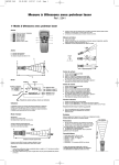
INTEGRATED STEREO AMPLIFIER
PMA-ZOOOIVR
OPERATING INSTRUCTIONS
“SERIAL NO.
PLEASE RECORD UNIT SERIAL NUMBER ATTACHED TO THE REAR OF THE
CABINET FOR FUTURE REFERENCE”
-Y
‘ro
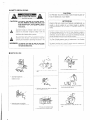
PREVENT
ELECTRIC
SHOCK,
MATCH
PLUG ‘I.0 WIDE SLOT, FULLY INSERT.
WIDE
BILADE
OF
POlJR iVlTER
LES CHOCS iLECTRIC&JES,
INTERODIJIRE
LA
1LAME LA PLUS LARGE
DE I..A FICHE
DANS
LA BORNE
CORRESPONDANTE
DE LA PRISE ET POUSSER JUSQU’
Al.1
FOND.
..-..
.._“_ ~
-.....
-.-._.._
.^ -
The lightning flash with arrowhead
symbol, within an
equilateral triangle, is intended to alert the user to tho
presence ot uninsulated “dangerous voltage” within ihe
product’s enclosure ihat may be of sufficienl magnitude to
constitute a risk of electric shock to persons.
.This device cornplies with Part ‘I5 of the FCr: Rules. C)peratron is subject to
the following two condibons: (I) Thrs device may not cause harmfrul
interference, end (2) this device must accept any interference received,
including interference that may cause undosir-ed operation.
---..-.
-.-~
__..
-.-.This Ciass B digital apparatus meets all requirements of the Canadien
Interference-Causing Equipment Regulations.
The exclamatron
poinl within an equilateral
triangle is
rntendecl to elert the user to the presence of important
operating end maintenance (ser.viciny) instructions rn the
literature accompanying the appliance.
Cet appareii nurneriquo de la c&se I3 respecte toruies ies exiyences du
Rkglemer~t sur le rnaternel brouilieur du Canada.
I.. ..--.
-
J
.__
@
-.-
. ..-__.__
-.__
e Handle the power cord carefully
-
-r-‘-~
~_
--_
~.-
--_.
-
‘,....-.
.~
..~
.._-
._-
I_
1.
2.
3.
4.
5.
6.
7.
8.
9.
10
1I
12.
Read
Instriclions
.- All Lhe safety and operating inslructiolI.5
should be read before the product is operated.
Retain Instruclions ....The safety and operaling instructions
should be retained for future referonce.
Heed Warnings - All warnings on the product and in Ihe
operating ins&uctions should be adhered to.
Follow Instructions - All operating and use instructions should
be followed.
Cleaning .- Unplug this pi.oduct from the wall outlel before
cleaning. Do not IIS~ liquid cleaners or aerosol cleaners.
Attachments ... Do 1101use attachments not recommended by
the product manufacturer as they may cause hazards.
Water and Moisture - Do not use this producl near water -.-for
example, near a bath tub, wash bowl, lkitchen sink, or laundry
tub; in a wet basement; or near a swimming pool; anrl the like.
Accessories - Do not place lhis product on an unstable cart,
stand, tripod, bracket, or iable. The product tnay fall, causing
serious injury to a child or aduli, and serious damage to l.he
product. lJse only with a c;rrt, sland, tripod, bracket, or table
recommended by the manufacturer, or sold with the product.
Any mounting of ihe product shoklld follow the manufacturer’s
instructions, and should use a
mounting accessory
recommended by the
manufacturer.
A product and (XI I
combination should be
moved with care. Quick
stops, excessive force,
and uneven surfaces may
cause the product and cart
combination to overturn.
Ventilation - Slots and openings in the cabinet are p~ovlded for
ventilation and to ensure reliable operation of the product and
to protect it from overheating, and these openings must no! be
blocked or covered. The openings should never be blocked by
placing the product on a bed, sofa, rug, or other similar
surface.
Tllis producr should not be placed in a buill-in
installation
such as a bookcase
or rack unless proper
ventilation is provided or the manufacturer’s instructions have
been adhel-ed ‘to.
Power Sources - This product should be operated only from
the type of power source itidicated on ,the marking label. If
you are not sure of tho Lype of powel supply to your home,
consuli your product dealor or local power co:npany.
Fatproducts intended to operate from battery power, or other
sources, refer to the operating instructions.
Grounding or Polarization “. [his product may be equipped with
a polarized alternating.-current
line plug (a plug having one
blade wider than the other). This pl~ug will fit into the power
ok&let only one way. This is a safety feature. If you are unable
to insert the plug fully into the outlet, try roversin! ihe plug. If
the plug shoi~k~ still fail to fi’r, con&i your eiectrlclan io replace
your obsolete outlet. Do noi defeat the safety purpose of the
potarizod plug.
'I 3
15.
16.
1 1.
18.
19.
20.
%I
72.
23.
24.
25.
Power-Cord Prelection - Power-supply cords should be routed
so that they are not likely lo be walked on or pinched by items
placed upon or against them, paying particular attention to
cords at plugs, convenience receptacles, and the point where
they exit from the product.
Outdoor Antenna Grounding - If an outside antenna or cable
system is connected to the product, he sure the antenna or
cable system is grounded so as to provide some protection
against voltage surges and built-up staiic charges. Article 810
of the National Electrical Code, ANSI/NFPA 70, provides
informaiion with regard to proper grounding of the mast and
supporting structure, grounding of the lead-in wire to an
antenna discharge unit, siLe of grounding conductors, location
of antenna-discharge unit, connection to grounding electrodes,
and requirements for ihe grounding elecrrode. See Figure A.
Lightning - For added ptolection for Lhis product during a
lightning storm, or when it is left unattended and unused for
long periods of time, unplug iI from the wall outlet and
disconnect the antenna or cable system. This wilt prevent
damage to tlie product due to lightning and power-line surges.
Power Lines - An outside antenna system should not be
located it! the vicinity of overhead power lines or other electric
light or power circuits, or where it can fall into such power
lines or circuits. When installing an outside antenna system,
extreme care should be taken to keep from touching such
power lines or circuits as contact with them might be fatal.
Overloading - Do not overload wall outlets, extension cords, or
integral convenience rece{&cles as this can result in a risk of
fire or electric shock.
Object and ILiquid Entry .-. Never push objects oi any kind into
this prodlict through openings as they may touch dangerous
voltage points or short-au? parts that could result in a fire or
electric shock. Never spill liquid of any kind on the produel.
Servicing - Do not attempt to service this product yourself
as opening
or removing
covers may expose
you
to
dangerous vol,tage or other hazards. Refer all servicing to
qualified service personnel.
Damage Requiring Service - Unplug this pl-oduct from the
wall outlet and refer servicing lo qualified service personnel
under the following conditions:
a) When ihe power-supply cord or plug is damaged,
b) If liquid has been spilled, or objects have fallen into the
product,
c) if the product has been exposed to rain or water,
d) If the product does not operate normally by following the
operating instructions. Adiust only ihose controls that are
covered by the operating inslructions
as an improper
adjustment of other controls may result in damage and will
often require extensive work by a qualified technician to
resiore the produci to its normal operation,
e) If the product has been dropped or damaged in any way,
and
f) When the product exhibits a distincl change in periortnance
- this indicates a need for service.
Replacement Parts - When replacement parts are required, be
sure the service technician
has used replacement
parts
specified by the manufaclurer or have the same characteristics
as the original part. Unauthorized substitutions may result in
fire, electric shock, or other hazards.
Safety Check -. Upon completion of any service or repairs to
this product, ask the service technician to perform safety
checks to determine that the product is in proper operating
condition.
Wall 01 Ceiling Mounting - The product should be rnounted to
a wall or ceiling only as recommended by the manufacturer.
IHeat - .l’he product should be situated away from heat sources
such as radialors, hoat registers, stoves, or other products
(including amplifiers) thal produce heat.
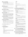
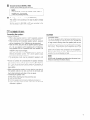
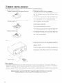
1. Always keep the POWER switch on the main unit turned on.
2. Turn the power on and off from the remote control unit.
3. Unplug the power cord when you do not plan to use the unit for a
long period of time
If only the MUTE/STANDBY LED is lit red, this means that the
power is turned off from the remote control unit. Turn the
power on from the remote control unit.
__
_13
m
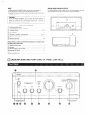
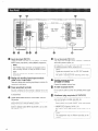
DESIGNATIONS AND
FUNCTIONS OF PANEL CONTROLS
q
CONNECTIONS
m
OPERATION
a
REMOTE CONTROI.. OPERATION _............ ,.....,...
.
.
.
@I TROUBLESl-fOOTlNG
a SPECIFICATIONS
,_...................._.....
..4 -’ 7
. . . . ..t.........................................
.
. . ....
.
.. .
. . . . ..,.....I
. ...
. .
7, 8
,.... I.,.. 9
I.,.... 10, 11
..o..............
(1) Operating Instructions
.....................................................
(2) Warranty ....... , ...............................................................
(3) Kemote Control Unit (RC-858) ...........................
. ................
(4) Batteries I?03 (AAA) ......................................
, ..................
(5) Power Supply Cord ...........................................................
(6) Service Station List ...........................................................
12
13
.I
,‘I
.I
.
:I
.I
For heat dispersal, leave at least 10 cm of space between the top,
back and sides of this unit and the wall or other components.
r ~~~~~~
1
When
Ihe power
switch
is tur,ned
ON (-1,
the
lights.
MUTE/STANDBY LED
is turned ON, power is supplied 10
When .llie power swil
the unit. It takes a few seconds after the power is turned
ori for the unit to warm up. This is due to the built-in
muting citcuil: tl~ai eliminates
noise dul-ing the on/off
operation.
.
e infra-red light &ansmitted from the
wireless remote control unit.
For remote control, poini the wireless remote control unir
towards the sensor.
88
1
This jack is used io plug in the headphones.
(The SPEAKI-IH outpul is turned off where the headphorles
are plugged in.)
To prevent hearing loss, do not raise ihe volume level
recol,ding from the tuner.
Used to recording
componenr
DVD/ AUX-1 terminals.
0
Copying
l/CD.-R.
10 TAPE-
position
when using the ‘tape deck,
to the TAPE-p/MD terminals.
elc.,
Use this position
when using ehe ‘Iape deck,
connected to the TAPE-?/CD-R terminals.
etc.,
Use this position when usilly the record player connected
to the PHONO terminals.
to switch the
Use ~l-ie CARTRIDGE selection switch
sensitivity to correspond to the cartridge
d to iisten a compaci disc player or other component
that is connected to the CD Lerminats.
play a component
TV tuner that is connected
6E:$
ce ~~~~~~~U
i:he balance between the left
s <nob is used to ad
and right channels.
\/Vhen it is se1 to the center position, the amptiirlde of the
amplifier is equal on both sides. If the volume on the right
side is too low, turn the knob to the right (0). If .!he volume
on the tef.t side is too tow, turm the Iknob to !he left (0).
This wilt achieve an eve11 balance on the left and right sides.
such as an FM/AM tuner or a
to the TUNER terminals.
component such as a HiFi video player, TV
luner or tape deck that is connected to the DVD/AIJX-‘I
terminals.
Used Lo play a component
tuner OI- tape deck that
ierminals. And power amp
using the P. DIRECT switch
Q ~~~~~~~U ~~~~~~~~
This knob conIrols the ovoralt volume level.
Turn the lknob 1.0Ihe right (0) lo raise the volume and to the
loft 0) to tower it.
cm‘
onto a
from TAPE-2/MD
ts
Use this
connected
1
This knob is used to cotltrol the treble quality of the sound.
Whet1 lhe knob is set at lhe center position, the frequency
characteristics
are flatlened in the range above 1000 Hz.
The treble is emphasized as the knob is moved off center to
the right (a), and reduced as it is moved to the left (0).
source fol- recording
is not possible
that conneci-ed to the AUX-
Use these to select the program source.
When the switch
for the desired
program
source
is
selected, its LED tights. One prograrn source only can be
selected at a time, as follows.
This knob is used to conlrol the bass qualily of the sound.
VVhen i he Iknob is set ai ilhe center position, the frequency
characteristics
are flattened in Iho range below 1000 Hz.
The bass is emphasized as .ihe knob is moved off center to
the right (0). and reduced as iI: is moved to the left (0).
output
to the
-2:
Used 1.0recording component
2 terrriinals.
I
I hat connected
/
such as a Hit? video player, TV
is connected
LO the AUX-2
direct terminal is selected by
on the back panel.
When selecting
the power amp direct terminal,
volume control function of this ullit does not work, so
set voturne tevel by the component connecting to this
lerminat.
tape deck, etc.
0
2:
The controls
se t IIS position when making copies of tapes using two
tape decks. .l.he input signal /torn the deck connected to
t/he TAPE-l/CL)-R inpcrt terminals is fed to the TAPE-Z/MD
REC 0U.i terminals.
Used to recording from the turr&bte.
0 cm
llsecl lo recording
from ihc CD player.
(BASS
When set io the ON
control circuit, providing
Irect y lo
high quality sound.
volume
I
This IID itashes while the muiing circuit is activated when
ihe power is ~.urned on and when muling is turned on from
nd remains lit (without flashing)
‘ihe remote control unit
is turned ON (..%).
while the power switch
’
I
1
These are input terminals
,for CD players,
iurntables,
A &l/FM tuners, tape decks or other playback components.
- ._.__
. ..__
I--
L.
Ths PHONO input terminals
are equipped with a
short pin-plug. Remove this plug to connect a record
player.
Store the rernoved short pin-plug in a safe place so as
not to lose it.
.--.---
connection
are outputted from the I%E OUT terrnitlals
1 even whet, using headphones.
’ No signal is outpuI:ied when selecting power amp
1
Connect the speaker systems
to tape decks.
power amp. set volume
to this terminal.
rng a power amplifier, a subwoofer
with built-in power an\plifier, etc.
Connect these PRE CIIJT ierminals to the input terminals on
the additional power amplifier, subwoofer, etc.
.__-._.- _...__._
is terrninal is directly
level by the component
fed to the
connected
ON position:
Power amp direct terminal
is selected
when INPUT
SELECTOR is set to AUX-2/f? DIRECT position.
OFF position:
AUX-2 is selected when INPUT SELECTOR is set to AUX-.
2/P. DIRECT position.
here.
cspt
Connecl the included power supply cord here.
Do not use any other cord than the provided power supply
cord.
uniis, such as tuner, turntable, tape deck, etc.
@ SWITCHED (Total capacity: 120 W / 1 A):
rhese outlets are turned ON/OFF when main power
switch is turned on/off.
(9 IINSWITCHED (Capacily: 24.0 W / % A):
This outlet is always ON whether power swifch is on 01’
Off.
-____-.quippment
--.-
may be dirierent
-
~.-
-- -.
according
lo the
-
J
Connect the turntable’s
ground wire here
is used to reduce
is terminal
xtable, etc., is connected.
lees not provide grounding.
----- ----
noiso
when
_-. -....-
a
-I
1
to the type of player cartridge
This switch is set according
to be used.
Set this switch IO MM (.@I,) or MC (-1
type of cartridge used or1 your iurntable.
according
to the
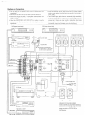
* Speaker impedance
0 When using speaker systems A and 6 separately, speakers
with an impedance of 4. ‘to 16 S.&hms can be connected.
@ When biwiring wilh biwireable speaker system, speakers
with an irnpeclance of 4 to 16 Q/ohms can be connected.
0 Note that when [ising two sets of speaker systems together
(A t- B), use speakers wth iinpedance
8 to 16 S./ohms,
using speakers with an impedance other than I)etween 8 to
‘I6 ~/Oht’nS may cause damageS.
Note that this unil is not equipped
with a switch for
selecting the speaker sysiem. The A and 13 speaker output
terminals are connected in parallel.
0 The proteciive
circuit tnay be activated if speakers with
other impedances are conr~ected.
* Be sure to connect the cords between the speaker terminals
and speaker systems with the same polarities (@ to CD, 8 to
0). If not, the central sound will bo weak and Che position of
the dif-Ferent instruments
witI not be clear, diminishing
the
stereo effect.
~3When connecting the speakers, he sure that the core wires of
the speaker cords do not slick out from the terminals
and
touch olher terminals, each other or the rear panel.
0 Connecting the speaker cords
@ Peel off the sheathing from the end of the cord.
@ ‘Twist the core wires.
0 Turn the speaker terminal counterclockwise
to loosen it.
@I Insert ,the core wires entirely,
then turn the terminal
clockwise ‘10 lighlen il.
This set is equipped with a high speed protective circuit.
This circuit protects the internal circuitry from damage due
to large currents flowing when the speaker jacks are not
completely connected or when an output is generated by a
shot-t circuit. This protective circuit’s operation cuts off the
output to the speakers. In such a case, be sure to turn the
power off and check the connections
to the speakers.
Then turn the power on again. After muting for several
seconds, the set will operate normally.
- -_._-I
1
NEVER touch the speaker terminals when the power is on.
Doing so could result in electric shocks.
--.
8
ot plug in The power
at-c
e to connect ‘rho leii and righe channels properly.
Incomplete
connectiotis
the plugs securely.
can
the SWITCHED
AC OUTLETS
to plug in aludio
onents.
Do not use them for hair dryers or o’clter
/
- --~
.-...______. -~cord until all connections
appliances.
e Note that placing ,ihe pin ~ILICJ cords next to power supply
cords 01 near power transformers rnay result in humming or
other noise.
0 Pl~e PHONO input jacks have an ex!remely high sensilivity,
so avoid turning up the volume vvhetl no pin plug cords are
cotlnecied.
Doing so may result in induc2ion humming
(booming) from ?l~e speakers. VVhen pin plug colds are nor
connected, insert ihe included short-circuit pin plug.
.-_____.-...--.-.
--
DVD player (sound only)
nnv,.
SPEAKER SYSTEM iR)
SPEAKEK SYSTEM !A)
$
CD player
Connect lhe ground wire,
but disconnect it ii humming
;P 3
ii Power aninlifier
-._-.--..~c-----~
Tape deck 01 MD recorder
LINE IN
(rlf-1cI
.INll OUTWI)
-,,- ^.--.
H
L
SPEAI<EH SYSTEM @I-WIHING)
When b&wiring with kwireable speakers,
connect the nrid and high range terminals
to SYSTEM !A) (or SYSTEM (RI), lhe low
range terminals I:O SYSTEM (13)(01
SYSTEM (A)!.
1. Set ,the HEC OIJT SELECITOR
* Make sure that all the connections
are proper by referring
to
switch
to ihe program
source you wish to record.
2. Play back ihe program source.
the rear panel.
a Check the polarity
(positive
and negative)
and tile directivity
of stereo
separation
of connections,
(right cord io right
channel terminal, r-nd IeFt cord to loft channel terminal).
0 Check the directiviry of pin cord connection.
3. Start recording with the component
l/CD-R” or “TAPE-2/MD”.
0 In the PMA-ZOOOIVR,
(headphona)
signal
knobs and switches
connec-ied
the REC OUT signal and the speaker
are output
circuits
so that
related to the tone and volume
via separate
have no
effect whal ever 011,the sound that is recorded.
* Turn the volume
minimum
control
lknob
counterclockwise,
I.0
recording
Function is selected
position.
to “TAPE-
Also, since the
by the REC OUT SELECTOR
the free program source can be played through
* Sat the rotary knot
or headphones)
the
even during recording.
@ Set SOlJRCE DIRE
Aflcr checking
the above items, turn on the power, the alnplifier
A recording
is se1 in l.lie ready mode in a few seconds.
in progress
three individual
A
~~~~
tape deck iI\ which a common
B
1. Set the CARTRIDGE
selection
switch
“MC
LEE)” or “MM
1”.
the volume
appropriate
and playback
cannot
if a .Lape deck with
and playback
I/CD-R
to “PMONO”.
and tone conlrols
to yield an
with
FIECORDtNG
condition.
be used to monitor
the
INPUT
MONITOR
is used. A
head is used for both recording
recording.
Irecording is being made using ‘TAPE-l/CD-R,
2.
the INPUT SELECTOH switch
3. Operate the turntable and play the
4. ‘lilrn
can be monitored
heads -for recording
SELECTOR
and pemil
will
When
selecting
engage
a
rAPEthe
a check of the recording
vol~~me and sound quality.
, set the REC OUT
1 Set LIE INPUT SELLECIOR switch
to “CD”.
2. Operale the CD player.
3. Turn i:he volume @ and tono controls
appropriate
volume and
sound
SELECTOR switch
---.-.-.1
to yield an
Copying is not possible from .TAPEG/MD to TAPE-I/CD-R.
qua!ity.
0 ‘This amplifier
‘I. Sel the INPUT SELECTOR switch
power
2. Operate the tune
3. Turn the volume
appropriate
to yield an
P L !AY I N
CI
1
~~~~~~
‘I. Set .the INPUT SELECTOR switcii
0
1.0 “OVD/AUX-‘I
” (UIJX-2/
I-? DIRECT) position.
2. Operate the Audio equipment
appropriate
SySiW7S.
@ and tono conitols
to yield an
volun~e and sound quality.
If power amp direct svi/itch (BACI< PANEL) is set to ON
position, powor amp direcl terminal is selecied when AUX-.
2/S? DIRECT is selected. (see
.~ --_____--.-.- . ..-
1. Set ,the INPIJ’I’ SELECTOR
“TAPE.2/MD”.
switcl\
@ to “TAPE.--l/CD-R”
OI
2. Opetate the iape Ueck.
3. Turn the volume
appropriate
back-
mode set before the power was turned off.
@ and tone controls
volume and sound quality.
3. Turn the volurne
has a full memory
is lurned on, INPUT SELECTOR
@ and tone controls
volume and :xx~ixf quality.
, @,
I.0 yield an
system.
When the
ale set to the last
The accessory
Remote Control Unij: is used to conl’ral the amplifier
fr-om a convenient
distance.
t> RC-858 uses the size HO3 (MA)
I. Remove the battery cover on the Remote Contr-ol Unit.
The baj:leries
dry cell batteries.
will need to be replaced
year. This will depend
upon how often
approximately
once a
the Remote
Control
Unit is (Ised.
If, in less than a year
inserted,
from
front a near-by position,
2. Insert two dry cell batteries
the battery supply
unit.
as shown
in the diagram
on
tho time
new batteries
were
the Remote Control Utnit fails to operate the Amplifier
(The included
it is time to replace the batteries.
battery is only for verifying
operation.
Replace i’j:
with a new battery as soon as possible.)
Insert
the battories
properly,
-following
the polarity
diagram
inside lhe battery cornpariment.
Eatteries are prone to damage and leakage.
$3 Do not mix new batteries
a Do not mix different
types of battories.
0 Do rrot jumper opposite
to heat, break then
3. Replace the battery cover.
Therefore:
with used ones.
poles of ihe batteries,
expose them
open, nor expose them to open fire
If the batteries have leaked, remove any traces of battery fluid
ftom the battery compartment
wiping thoroughly with a dry
cloth.
Then insert new batteries.
Q Operate the Remote Control Unit while pointing
Remote
Control
Sensor
on ihe AmpliFier
it towards
as shown
the
in the
diagram on the left.
0 The Remote Contr-ol Unit can be used at distances
8 meters in a straight
decrease
line from the amplifier.
if there at-e ohstructiorrs
transmission
or if the Remote
slraight at the ampliher.
blocking
Control
up to aboui
This distance will
the infra-r-ed light
Unit is not directed
Do not press the operating buttons on the Amplifier and the Rornote Control Unit at the same time. This will cause rnisoperation.
a Operation of the Remote Control Unit will become less effective 01. er-ratic if the infrared &mote
Control Sensor on the Amplifier is
exposed to strong light or if there are obstructions between the Remote Control IJnit and the sensor.
0 In case you operate a VCR, TV or other components by remote control, do not operate buttons on tvvo cliiferent remote control units
at the same time. This will cause misoperation.
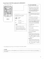
to control the PM&20001VR.
When pressed, the main unit’s power
LED flashes and the speaker output is
turned off. When pressed again, the
mute mode is canceled and the power
ILED stops flashing (remaining lit).
- .__I__-.-...
-. .-...
c
_....
.._ -..-.-___.-..-.-.
Use these to co~rtrol the CD player
connected to the PMWOO01VR.
-.
: Playback
: stop
E
: I'zlllSc:
: Auto
soarcl1
(to beginning of trmck)
: Au 10 search
(to beginning of track)
DENON pot-table CD players and
other CD players, the auto
II ~notle is set when the I
button is pressed shortly then
ed, and the manual search mode
when one ol the buttons is held
, ihe main unit’s power switch is set
to the ON/STANDBY position (
this to turn the IWA-200OIVR’s power on
and off.
@When the power is turtled off from the
rernote control unit, the main unit’s
power i.fD remains lit, but the input LED
turns off, indicating that the PMA20001VR is in the standby mode.
e When the main unit’. owec button is set
power off from the remote control unit
and then set back to the ON/STANDBY
), the PMA-2000TVR IS set to
While this is pressed, the main unit’s
volume control turns clockwise and the
volume increases.
While this is pressed, the main unit’s
volume control turns counterclockwise
and the volume decreases.
e this to select tire program source to
be played. The function switches in the
fo!lowing order each time this is pressed:
CD - ‘I-UNER --t DVD/AlJX-1 3 AUX-2,’
I? DIREC-T -mi-TAPE-2/MD -* TAPE-l/CD-R
-> Pt-ION0 - CD
8:
FII
iJse this to select the program source to
be played. The function switches in the
iollowing order each time this is pressed:
CD 4’ H-iONC~ --b TAPE-l/CD-R -B TAPEZ/MD - AUX-2/P. DIRECT - DVD/AUX-1
-I_ TUNER -t CD
Q The TK-850 Remote Contrn~l Unit Cian control CD players marrufactured
f\ Note that operation may riot 1x3 possible for some models.
Some of the functions of the PMA-2.0001VH can also be controlled
main amplifiers.
..__
___--..~
by DENON
with the ~-emote control units included
wills other DENON pre-
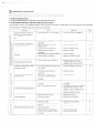
IF the set does not seern to be operating properly, check the points listed below. If these points do not apply, the set rnay be darnagod.
Turn off the power immediately and contact your store oi put-chase
-~.--
- ___-
I_---.
--.-.
0 Power supply cold is not connected.
.-_____-.
~.* Cite& that tho cold is plugged in.
light and no sound is produced
when POWER switch is turned
MUTE/STANDBY l.ED lights but
no sound is produced.
INPUT SELECTOR is not set to
* Set to the proper posilion.
VOLUME control turned down.
* Set lo an appmpi late level.
.- .-~__0 Connect securely.
* Speaker cords IIO? properly
Sound is not produced from one
-. ____
._ -_____-
Volume level is different when
listenitrg to tuner and records.
5 Connect securely.
0 Adjust the I9&4NCE
5, 3
.--~
-
8
contr-ol.
..--. .-____
.-. --.~~ _ .~
*aTuner ot- record output is different.
* Check tho left/right connectiorrs.
~* Turntable’s gr-ound wire is not
___-..
@Connect securely.
___
7, 8
.-.
/
/ @Connect securely.
Booming sound produced when
connected to PHONO terminals.
0 Influence from a ..rvor VCR near the
5
;;
0
(I)
E
2
u
2
CL.
Howling produced when volume
is turned up while playing records.
____-...-.
too close.
* Floor is soft and vibrates easily.
-~-..____ @Stylus pressure is too light.
Sound is distorted.
* Batteries are dead.
@Remote control unit is too iar from
This unit is not operated properly
when remote control unit is used.
-~___--.-
* Use cushions to absorb the vibrations
transmitted from the floor to the
speakers. Ii ihe turnrabte does not
include insulators, use audio
insulators, availahlo iii stores.
__--~
0 Check the tip of the siyttrs.
0 Replace iho cartridge.
.-___
-~-..
.___-.
z
8
$2
p
5
cc
5, 9
.__
7, 8
/ * Obstacle between this unit and
/
remote control tit+..
j * Drfferent button is being pressed.
n @ and 8 ends of battery is inserted
in reverse.
-.
_.--_-~
- --
* Move ctoser.
‘1 Helnove olxmcto.
u Press the proper button.
@’Insert battories properly.
8
8
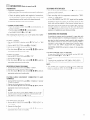
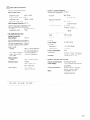
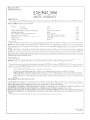
80 w + 80 w
(8 G/ohms Load)
20 HZ i0 20 kl-lz, -i-.1-I.D. 0.07 %
16OW+ .lFjOW
(4 G/ohms Load)
circuited)
rJlN, I
circuited)
MC:
SC)URCE~-DIRECT: ON
CD, TUNER,
ki-lz,
MM:
89 dR
(at 5 mV input)
(input terminals
T.1H.D. 0.7 %
short74. dR
(at 0.5 mV input)
I3/D/AUX--1 I AUX-2,
T,4PE-l/CD-.R, T/APE-2/MD:
108 dB
Tme
‘I 50 nlV
BASS:
IOOHzGdB
TREBLE:
IO kHz -r-t3dB
~~~S~~~~~~~~~~~~~~~~~~~~
value in parentileses
the input impedance
DIRECI
e:
~~~~~~~
AC120V,BOHz
( )r
when SOURCE
Switched
is ON.
MM: 2.!5 mV/47 kQ/kohms
PHONQ:
MC:
700
IN/l
00 s2/011ms
x 2:
i A / 120 W (Total)
2Af240W
6.0 A
CD, TUNER, DVD/AUX.~l I 135 mV/4-7 kQ/kohms
(135 IYIV/I2 kQ/kohms)
AUX.2, TAPE-l/CD~-R,
434 (W) x 180 (HI x 478 (D) mm
.l-APE-2/MD
24.0 ltg (52 Ibs 14.7 oz)
(17..3/32” x 7-5/64”
B
20 HP -I 20 j:lHi. z1:0.5 dB
PHON0
MM: .I,30 mV/l
MC: IO m\//l
x 1%13/16”)
Infrared pulse system
kHz
kl-lz
3 V DC, Two size 1703 (AA/A) dry
cell batteries
Pl?[i I-‘IlI_ 0.9 v
56 (WI x 105 (I-I) x 19 (D) mm
(Input CD 135 mV)
(2..3/16” x 4-l/8”
x 23/32”)
70 g (Approx. 2.47 oz)
(includitlg
% Maximum dimensions include controls, jacks, and covers.
(D) :- depth
(W) :: width,
(I-1) = heighi,
~3 For improvement
purposes,
specifications
and Iunctions
are subject to change wi.ihout advanced notice
batteries)
‘I 6-I 1, YUSWIMA 3-CHOME, EWNKYOIJ--KCI, TOKYO 113-0034, JAPAN
Tolepl~orw (03) 3837-53~1
Prmted iri Japan 51 1 3917 001
Audio Products Australia Pty Ltd. 67 O’Riordan Street, Alexandria NSW 2015, Australia
Tel: (02) 9669-3477 Fax: (02) 9578 -0140
Digital-Professional-Audio
Vertriebsges.m.b.H.,
1170 Wien. Hupertusplalz 3
Tel: 0222~4501006- 9, Fax: 0222-457679
Transtel-Sabima P.V.B.A. Harmoniestraat
13, 2018 Antwerpen 1, Belgig Tel: 03-237-3607
Denon Canada Inc. 17 Denison Street, Markham Onlario, Canada L3R 1135 Tel: 905-475-4085
Fax: 905-475-4159
~~~~~~~~~~~~~I~,~,
(J~~~~~~~~~~~~~~l~l~~,)
~l;~~g.~&~~
~~]:189r~~~~.;ki~~l~z~~~~
f&/3]@: ‘too005
@$&. : (010) 64064558
I$g:
(010) 64.015151
A~~~~-t~~~~~~~~~~~~~~~H~~~~,(~z
~~@&~~zLX$$253~j! !@Q : %00062
‘ZE$ : 86-21-6257-9958
#g:
86-2’1-6260-564.5
EUROSTAR OSTORAVA s.r.0. areal Vodni stavby PI-aha a.s., budova A2 Dobronicka 6X$14.8 00 IPraha 4 Czech Rep.
Tel: 02-611 I-2901 Fax: 02-611 I.-2904
Hifi Kluhben A/S Dali Alle I I 9610 Noerager, Denmark Tel: 45-96 72 10 00 Fax: 45-96 ‘72 10 ‘I 4.
Suornen Hi-Fi Klubi 0Y Nylandsgatan 4-6, Helsingiors
Tel: 09 25 30 36 1%
Denon France S.A. 3 E3oulevard Ney, 75018 Paris Tel: 44-89-68-69
Denon Electronic GmbH An der Landwehr ‘IS, 4.1334 Nettetal Tel: +49 2157 ‘I 2 fJ8 78 Fax: -1-49 2157 12 08 13
KINOTECHNIKI IITD. 14, PYRGOU STR. 166 75, GLYFADA ATHENS Tel: (Ol)!XC)-~‘I071 Fax: (01)960-‘IO72
DENQN ASIA COMPANY L.TD. Suite 501, Ocean Centre, Harbour City, Canton Road, Tsimshatsui IKowloon, Hong IKong
Tel: 852-2516-6862, Fax: 852-2516-5940
g E&$$j: 852,.2!j’f
r&($@j’j
f’@‘$J : 852-251
fj&C&J()
X#l~%34r(B?~~l>Rl@~2~ mwl.aa “‘~~~Ji!lal#i~~~~~~~~~~~~r~,~~5~.~501
InfoVox Ltd. Terez krt. 3’1 I ‘I 067 Budape;; Hungary Tel / Fax: 01.302-2515
Japis Ltd. IBrautarholt 2, P.O.Box 396, 121 Reykjavik, Iceland Tel: 354-58009-800
Fax: X4-5800-888
Newpan Ltd. 14 Rosansky st. Rishon Lezion 75706. Tel: OX%35900
Fax: 03-9616193
PT Autoaccindo Jaya. Cideng Barat No. 7 Jakarta, Indonesia Tel: 633-2730
Audiodelta S.r.l.‘l9 Via Pietro Calvi 20129 Milan Italy
Tel: X3-02-54 1 l-6008 / X4-02-541 2--8253 Fax: 39-02--5518-I 961
SAM WON KOREA Co., Ltd. 1 F, SANG-ROCK BLDG, N1629-3 SEOCHO-DONG, SEOCHO~KU, SEOUL 137070, I<OREA
Tel: 02-521-1404
Fax: 02-3486-2’135
HWEE SENG (EL..IXlI?ONICS) SDN BHD. 13-1, Jalan Raja I..aut, 50350 Kuala Lumpur Malaysia
Tel: 60-3-4041-8422
Fax: 60-3-404.1-0563
Labrador, S.A. de C.V. Callejon del Naranjo 35, Naucalpan, 53560, Edo. Mex., Mexico Tel: 52-5359-5161 I-ax: 52-5357-I 775
Penhold E.V. Poppenbouwing
58, NL-4191 NZ Geldermalson, Netherland Tel: 31-345588 080 Fax: 31-34.5-588 085
Avalon Audio Corps. Limited 6306 Great South Road Ellerslie Auckland, New Zealand Tel: 64-9.,579-l 280 Fax: 64-S-57%33!jO
Hi-l? Klubben AS Sandakerveien 64 04.83 Oslo Tel: 47 22 79 66 66 Fax: 47 22 79 66 67
HORN DISTRIBUTION S.A. Ulica Kurantow 34, 02-873 Warszawa Poland
Tel: -14.8 22 649 30 71 Fax: +48 22 649 31 99
Videoacustica
Ota. Do Paizinho-ArmazBm 5Estrada De Circunvala@@Apart.
3’127 1303 Lisboa Codex
Tel: (O’l)417.-00-04/00-96
Fax: (011418-80-93
Hwee Seny (Electronics) Pte Ltd. 81 Genling Lane WO2-02, Everich Industrial Building Singapore 349566
‘Tel: 65-746-3355
Fax: 65-743-l 704
Mandarin Distributors S.A. 10 Thora Crescent, Wynberg Ext.3 Sandton, P.O.Box 5137, Johannesburg Republic of
South Africa Tel: 27.-l ‘l-444-8445
Fax: 27-I ‘i-444.-8363
Gaplasa S.A.AV. Ing. Conde de Torroja, 25, 28022 Madrid Tel: 91-329-29-60
Fax: Yl-:3X--‘i&75
Sveriges Hi-Fi Klubb Box 5116, S--402 23 Giiteborg Tel: 031 33 51000
KOENIG APPARATE AG, Abteilung Elektronik. Eggbijhlstrasse
28, 01-8052 Ziirich, Switzerland
Tel: 01-306-1626
Fax: Ol-306-‘1690
KOLIN.-DENON ENTERTAINEMENTY
INC. 5th FL..,NO.63, Po-.Ai Road, Taipei, Taiwan, R.O.C.
Tel: (0212381-5876 Fax: (02)2381-5811
~?g*~&gg$~~~~~~~fiq
&li;i&@~~@3&~l
O,@ f@~ : (02)2381-5876
@.;&I : (02)2381-5811
Mahajak Development Co., Ltd. 46 Mahajak Building, Sukhumvit Soi 3 (Nana-Nua) I<longtoey, Bangkok
Thailand. 10110 Tel: 66-Z-256-0020
Fax: 66-2,-253-l 696
IHayden Laboratories Ltd. Hayden House, Chillern Hill, Chalfont St Peter,
Gerrards Cross, Bucks, SLS SUG Tel: 01753-888447
Fax: 01753-880109
DENON ELECTRONICS, a Division of Denon Corporation (IJ.S.A.) 19 Chapin Road, Pine Brook,
NJ 07058-9777 Tel: 973-396-7499,
Fax: 858-544-8434
s Ii there IS 110service center in your local area, consult the ok&let where ihe equipment was purchased.
t
f
*
x
*
x
*
*
Falls sich in lhrer N&he keine Kundendienstslelle befindet, vvenden Sie sich an das Geschbfi, wo das Gergt gekaull wurde
S’il n’y a aucun cenire de service dans votre rbgion, consultez votre revendeur.
Se nella Vostra zone non c’B ii centro cii servizio, rivolgele Vi al negozio dove avete acqwslalo I’apparecchio
Si (no hay centros de sewicio en su &a local, conwire en donde haya comprado SLIequipo.
Als er in uw streek geen reparatie-inrcchting is, neemi u kontakt op met de vestiging waar II de apparatuur gekocht hoeft.
Saknas servicecentral I n6rheten d& du bar, biir kontaki tas med6terfBrs;ii)aren i6r apparater.
Se ~nCioexislir urn centro de serv,Cos em sua area local, consuiie o estabelecimento onde o equipamento loi adqwido.
,~g~l&fgll~~~qa~,~ ’ qn#Ji@
?&&$#3~&@]
*
HI 1001
B
13-16-I I, YUSIiIlvlA, BIJNKYO-KU, TOKYO ‘I 13-0034, JAPAN
Telephone: 18131 3837 532 1 Fax: (8131 3837 7804
Printed in Japan 5 I5 0921 005 EU I ‘IO
,,
“,,
,,-“,
.-,--_
-..“”
U~~~.~~
NAME
-__
,,,~
,“,_---~
-“--ll__.“-_
----_._
^“,
“---~ ^“-~~-
l__l~-~-
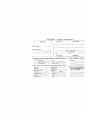
PURCHASER’S NAME
IXALER
ADDRES:i
.,... .-..--.^-I_“_ __---...
-.-
I
I l.,--.-.”
__lllllllll.l”ll~~“..---_^.
snw3
.-.~.
ADDRESS
----
-._
--
AREA CODE
% do
neza
C)
1.
2.
3.
4.
0
fl
n
~YI
Advertising
Denon brand name
PIOdllCi fealures
Friend/Relative
5.
6.
7.
8.
El
n
n
n
Price
Pruduct brochure/literature
Salesperson
. .._
Other(specify:
Category
)
Price Level
Ian
mm”
-
!
I