1
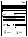
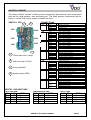
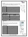
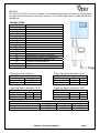
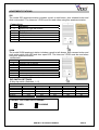
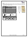
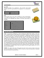
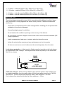
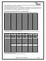
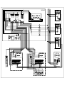
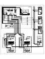
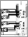
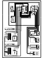
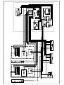
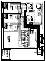
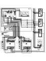
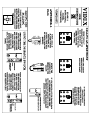
SENTRY 1
TECHNICAL MANUAL
TECHNICAL MANUAL
EDITION 1.6
SENTRY1 TECHNICAL MANUAL
VER1.6
CONTENTS
Manual Introduction
System Introduction
System Components
System Operation
Vandal Resistant Panel layout and sizes
Installation
Block Diagrams
Cable Size tables
Testing the installation
Telephone Connections Compatibility Chart
Accessories Connection Guide
Standard wiring diagram
Isolated system wiring diagram
800 Series door panel wiring diagram
Video system wiring diagram
Apartment station system wiring diagram
Trouble Shooting Guide
SENTRY1 TECHNICAL MANUAL
PAGE
2
2
2 – 12
13
14
15
16
17
18
19
20
21
22
23
24 – 25
26
27 - 28
VER1.6
MANUAL INTRODUCTION
The information is this manual is intended as an installation and commissioning guide for
the Sentry1 system. This manual should be read carefully before the installation
commences. Any damage caused to the equipment due to faulty installations where the
information in this manual has not been followed is not the responsibility of Videx Security
Ltd.
VIDEX run free training courses for engineers who have not installed the sentry1 system
before. Technical help is also available on 0191 224 3174 during office hours or via e-mail
[email protected].
SYSTEM INTRODUCTION
The Sentry1 system is primarily a multiple entrance audio or audio/video system. The
system has no limit on the number of apartments for which it can control although we
suggest using this system on small to medium sized installation of no more than 20
apartments.
The system benefits from advanced features such as full privacy of speech, fully privacy of
lock release, adjustable calling time, speech time and door open time and the facilities for
both push to exit button and tradesman button. There are many optional extras available
for the system including full line card isolation, door monitoring and access control (coded,
proximity, Bio). A range of options are also available for the apartments including a range
of telephones with varying facilities, videophones, extension sounders and strobes.
SYSTEM COMPONENTS
A standard audio system will comprise of two door panel, control cabinet and audio
telephones. A standard video system will comprise of a door panel, control cabinet, video
splitters and videophones. The individual parts are described below.
DOOR PANELS
Door panels from the 800 Series (Using the 837 amplifier), 4000 Series (Using the 4837 or
4832 amplifier) and vandal resistant (Using the 437 or 537 amplifier) range can be used on
the Sentry system.
Art.437 or 537 Amplifier + Connector PCB
Connection
Function
1
Receive speech from apartment
2
Transmit speech to apartment
3
Switched +12Vdc input
4
0V (Ground)
CB
A
1
2
10
Button common connection
Trigger from door
Push button 1 output
Push button 2 output…………
Push button 10 output
Art.837 Amplifier connections
Connection
Function
2
Transmit speech to apartment
~
13Vac input for name plate lights
3
Switched +12Vdc input
1
Receive speech from apartment
4
0V (Ground)
~
0V input for name plate lights
X
Not Used
P2
Push button 2 output
P1
Push button 1 output
C
Button common connection
SENTRY1 TECHNICAL MANUAL
VER1.6
Art.4837 Amplifier connection
Connection
Function
C
Buttons common connection
C1
Calltone out (Not used on Sentry)
P1
Push button 1 output
P2
Push button 2 output
S1
Common relay (Not used on Sentry)
S
Normally Open Relay (Not used)
RL
0V relay trigger (Not used on Sentry)
0V Ground
1
Receive speech from apartment
+
Switched +12Vdc input
2
Transmit speech to apartment
P3
Push button 3 output
P4
Push button 4 output
Art.4832 Amplifier connection
Connection
Function
I
Camera power input (14-20Vdc)
F1
Camera 0V
M/V2
Video Screen or Video sync+
V/V1
Video centre core or Video syncC
Buttons common connection
C1
Calltone out (Not used on Sentry)
P1
Push button 1 output
S1
Common relay (Not used on Sentry
S
Normally Open Relay (Not used)
RL
0V relay trigger (Not used on Sentry)
0V Ground
1
Receive speech from apartment
+
Switched +12Vdc input
2
Transmit speech to apartment
P3
Push button 3 output
ART.136 AMPLIFIER (Software version 136-12 or later)
680R
Connection
1
2
+ (3)
- (4)
5
T
PTE
C
NC
NO
D+
DBSY
SL
F1
Function
Receive speech from apartment
Transmit speech to apartment
+12Vdc input (Amplifier connection 3 on the Sentry 1 PCB)
0V (Ground) (Amplifier connection 4 on the Sentry 1 PCB)
Link to terminal – when used on Sentry 1 system
Electronic call tone output to common side of call buttons (NOT USED ON SENTRY 1 SYSTEM)
Link to terminal 5 when used on Sentry 1 system
push to exit button to trigger door release relay (NOT USED ON SENTRY 1 SYSTEM)
Common connection of dry contact relay (NOT USED ON SENTRY 1 SYSTEM)
Normally closed connection of dry contact relay (NOT USED ON SENTRY 1 SYSTEM)
Normally open connection of dry contact relay (NOT USED ON SENTRY 1 SYSTEM)
External link to door open (+12V side) LED.
External link to door open (0V side) LED.
Busy signal (NOT USED ON SENTRY 1 SYSTEM)
Switched 0V output to switch on video PSU. (NOT USED ON SENTRY 1 SYSTEM)
Switched 0V output to switch on camera. (NOT USED ON SENTRY 1 SYSTEM)
ON
Dip-switches and
jumper setting
1 2 3 4
on Art.136
amplifier
When using the Art.136
amplifier with the Sentry 1
system, all dip-switches
must be off
H
L
Position H
High volume reassurance tones
Position L
Low Volume reassurance tones
No Jumper
No reassurance tones
This jumper will not adjust the reassurance tone on
the Sentry 1 system
IMPORTANT NOTE (Art.136 Amplifier only): A 680R resistor needs to be fitted across terminals 1 & 3 of the
amplifier and a wire link across terminals 5 & - of the amplifier.
Speech volume adjustments are carried out at the door panel using a small trimmer driver.
Adjustment for
speech volume level
at the door station
SENTRY1 TECHNICAL MANUAL
Adjustment for
speech volume at the
apartment
VER1.6
DOOR PANEL DIODES
When using the sentry1 system, diodes are required on every door station to indicate to
the sentry1 PCB which entrance the call is coming from. If using only a one button
entrance then only two IN4001 diodes are required, if there are multiple buttons on the
door station then a diode board would be fitted.
Terminal A of sentry 1 PCB
Terminal C of apartment phone
Terminal CB 12V dc
SENTRY1 TECHNICAL MANUAL
VER1.6
CONTROL CABINET
The control cabinet consists of three primary components plus optional extra components
such as line card isolation, door monitoring etc. The three primary components are the
Sentry 1 control PCB, power supply unit and time clock.
SENTRY 1 PCB
1
CONNECTIONS
2
CN1
CN4
3
CN3
Function
12Vdc input power
12Vdc output
Negative input
Negative output
CN2
NO1
CO1
NC1
NO2
CO2
NC2
Door 1 relay contacts 1
Door 1 relay contacts 1
Door 1 relay contacts 1
Door 1 relay contacts 2
Door 1 relay contacts 2
Door 1 relay contacts 2
CN3
NO1
CO1
NC1
NO2
CO2
NC2
Door 2 relay contacts 1
Door 2 relay contacts 1
Door 2 relay contacts 1
Door 2 relay contacts 2
Door 2 relay contacts 2
Door 2 relay contacts 2
CN4
12V ( + )
7(-)
5(P)
4(T)
2a ( 2 )
1a ( 1 )
12V supply to phones
Negative supply to phones
Lock trigger from phones
Call tone to phones
Receive speech to phones
Transmit speech from phones
CN5
A
4
3
2
1
ENG
Trigger from door 2
Negative supply to amp (door 2)
Switched 12V supply to amp (door 2)
Transmit speech (door 2)
Receive speech (door 2)
Engaged output (high when call in progress)
CN6
A
4
3
2
1
CB
Trigger form door 1
Negative supply to amp (door 1)
Switched 12V supply to amp (door 1)
Transmit speech (door 1)
Receive speech (door 1)
Button commons
CN7
TC3
TC3
TC2
TC2
TC1
TC1
Time clock connection
Time clock connection
Trade button for door 2
Trade button for door 2
Trade button for door 1
Trade button for door 1
CN6
CN7
4
12Vdc input fuse (1amp)
2
Call tone fuse (315mA)
3
6 way dipswitch
4
Terminal
Vin
Vout
GND
GND
CN5
CN2
1
CON
CN1
System status LED’s
SENTRY 1 DIP-SWITCHES
CALL TONE TIME
SW1
ON
OFF
OFF
ON
SW2
OFF
ON
OFF
ON
CONVERSATION TIME
TIME
1 Second
2 Seconds
4 Seconds
8 Seconds
SW3
ON
OFF
OFF
ON
SW4
OFF
ON
OFF
ON
TIME
16 Seconds
32 Seconds
60 Seconds
120 Seconds
SENTRY1 TECHNICAL MANUAL
RELAY TIME
SW5
ON
OFF
OFF
ON
SW6
OFF
ON
OFF
ON
TIME
2 Seconds
8 Seconds
16 Seconds
40 Seconds
VER1.6
Sentry 1 Status LED’s
The Sentry 1 PCB incorporates four LED's which are used to indicate what state the PCB
is in. These LED's are labeled D10, D11, D12, D13. They relate to the following functions:D10 : When this is illuminated, the system is awaiting a call.
D11 : When this is illuminated, the system is busy.
D12 : When this is illuminated, the call is from door one.
D13 : When this is illuminated, the call is from door two.
Sentry 1 Jumper (JPR1)
The Sentry 1 PCB includes a link option (JPR1) which when in position A, the system will
only allow one call to be activated at anyone time. The system must timeout before
another call can be registered. When the link is in position B the system will allow another
button to be pressed without waiting for the system to timeout. (The link should only be
fitted in position B when the system is being tested or being used as a one door system).
POWER SUPPLIES
A control cabinet for an audio system will contain a 13.8Vdc PSU with battery back up
facility. The standard power supply is rated at 1 Amp. (Care should be taken to calculate
the current consumption of the lock release as it may be necessary to upgrade this power
supply to either a 2 Amp or even a 3 Amp). Video control cabinets will have an additional
PSU rated at 20Vdc 1 Amp surge or 800mA continuous. They additional power supply is
described below which is used to power the video phones
Art. 893N
20Vdc 800mA continuous 1A surge PSU. This power supply only has an output when
either a 0V is applied to –C or when a voltage is applied to +C. At all other times the +
output is switched off.
Connection
230V~ 0
+
-C
+C
D+
Function
Mains voltage input
Switched 20Vdc output (Triggered by –C or +C)
0V
0V trigger input (From 4V to 0V)
+ volts trigger input (From 8V up to 30V)
+20Vdc output via diode
SENTRY1 TECHNICAL MANUAL
VER1.6
TIME CLOCK Art.701
BST/GMT digital time clock. This time clock operates from a 12Vac
or dc power supply. The output is a dry contact relay. When used
with the Sentry1 control system, the relay is used to short the time
clock inputs on the sentry1 PCB which will in turn enable the trade
button input to accept a short from a trade button. This will then
energise the lock relay on the Sentry1 PCB.
Connection
Function
+
12Vac or dc voltage input
0V
TR
Not used with Sentry system
C
Common connection on relay
NO
Normally open connection on relay
NC
Normally closed connection on relay
For more information see time clock instruction sheet
OPTIONAL ISOLATION PCB
1
2
3
3
5
1
2
3
4
5
5
5
5
An isolation card will prevent a fault in a single
apartment affecting the rest of the system. The
isolation card has four channels (One card required
for every four apartments) and can be mounted in
the main control cabinet or in riser boxes.
Operation:
The isolation card will trigger an output when it
receives a positive voltage on either A, B, C or D.
4
4
4
4
The output will stay triggered as long as the SW+
Power and phone commons from Sentry terminal has 12 volts present. Once the 12V is
PCB
removed from the SW+ terminal the output will
switch back into isolated mode. The inputs A-D are
Select lines from call buttons
from the call buttons at the door panel and the SW+
Call tone & +12V to phones fuse
is switched by the Sentry1 PCB (Terminal 3 of the
amp). Four LED’s on the PCB indicate when an
Phone connections to apartment
output is live.
Output live LED
SENTRY1 TECHNICAL MANUAL
VER1.6
APARTMENT STATION INTERFACE PCB
The intercom 3 apartment station
interface PCB is required whenever
the 500, 500M or 500ST apartment
station are used. This PCB converts
the duplex speech into simplex
speech and controls the switching of
the apartment station
3
1
2
1
CN1 Connections in from Sentry1 PCB
2
CN2 Connections out to apartment station
3
Volume adjust
CON
Terminal
Function
CN1
+12V
Gnd
3
4
2
1
5
+12Vdc In
Ground
Switched 12Vdc
Calltone
Receive Speech
Transmit Speech
Lock Trigger
CN2
1
6
2
3
5
+12V
Lock button
Talk button
Switched 12Vdc
Speaker
Ground
+12Vdc Out
NOTE
In the event of the speech needing to be adjusted to eliminate feedback or to increase the
speech volume to an acceptable level the following two options are available :Option 1. The speech can be adjusted at the door panel amplifier by adjusting the two
volume controls (One for transmitting to the apartment and one for receiving from the
apartment).
Option 2. There is also a volume POT [VR1] on the intercom 3 PCB. This will adjust both
directions of speech at the same time and is only intended for situations when the volume
cannot be adjusted sufficiently at the door panel. (Note: This will also adjust the call tone
volume both at the door and at the apartment station).
AUDIO TELEPHONES
Art.3121
The Art.3121 includes a three position call tone volume control, lock
release push button and spare dry contact push to make button for
other services.
SENTRY1 TECHNICAL MANUAL
VER1.6
CONNECTIONS:Function
Transmit speech to the door panel
Receive speech from the door panel
Call tone in from Sentry1 PCB
Switch 0V lock trigger command
0V
Select line (Switches on telephone)
Dry contact switch
1
2
T
P
C
8
9
Art.3123
The Art.3123 includes a three position call tone volume control, lock
release push button and spare dry contact push to make button for
other services. Additionally it includes a slide mute switch with LED to
turn the phone off when the tenant does not want to be disturbed.
CONNECTIONS:1
2
T
P
C
8
9
Function
Transmit speech to the door panel
Receive speech from the door panel
Call tone in from Sentry1 PCB
Switch 0V lock trigger command
Not Used
Select line (Switches on telephone)
Dry contact switch
SWITCH PCB
+/~
0V
+12V for mute LED
Art.3125
The Art.3125 includes a three position call tone volume control and
large lock release push button. Additionally it includes a push on push
off mute switch with status LED and a door open LED.
CONNECTIONS:1
2
T
P
C
D
+12
Function
Transmit speech to the door panel
Receive speech from the door panel
Call tone in from Sentry1 PCB
Switch 0V lock trigger command
0V
Select line (Switches on telephone)
Switched +12 in for door open LED
+12V for mute circuit
SENTRY1 TECHNICAL MANUAL
VER1.6
Art.3126
The Art.3126 includes a three position call tone volume control and
large lock release push button. Additionally it includes a push on push
off timed mute switch with status LED and a door open LED.
CONNECTIONS:1
2
T
P
C
D
+12
Function
Transmit speech to the door panel
Receive speech from the door panel
Call tone in from Sentry1 PCB
Switch 0V lock trigger command
0V
Select line (Switches on telephone)
Switched +12 in for door open LED
+12V for mute circuit
JUMPER SETTINGS:FIVE SETTINGS ARE AVAILABLE FOR THE PRIVACY TIME
Jumper in position A
15 Minutes
Jumper in position B
30 Minutes
Jumper in position C
2 Hours
Jumper in position D
4 Hours
Jumper in position E
8 Hours
SET THE PRIVACY LED TO FLASH OR ON CONSTANT
Jumper in position FL
Flash the privacy LED
Jumper in position FX
LED on constant
VIDEOPHONES
901D
The Art.901D (901D/C for colour) includes a lock release
push button and a dry contact push to make spare push
button for other services.
CONNECTIONS:1
2
T
P
C
V
M
M
+12
+20
Function
Transmit speech to the door panel
Receive speech from the door panel
Call tone in from Sentry PCB
Switch 0V lock trigger command
0V
Select line (Switches on telephone)
Centre core of coax
Screen of coax
0V
+12V out to power video splitter Art.894
Switched +20V in to power videophone
SENTRY1 TECHNICAL MANUAL
VER1.6
Art.3313
The Art.3313 (3413 for colour) includes a lock release push button and two dry contact push
to make spare push buttons for other services. An Art.3980 back plate is required with this
videophone.
CONNECTIONS:1
2
3
4
5
6
7
8
9
10
11
12
13
14
15
16
17
18
Function
+12V out to power video splitter
Not used
Spare button
+20V power input
Door release command
Transmit speech to door panel
Receive speech from door panel
0V (Ground)
Not used
Local call tone input
Coax centre core or non-coax syncCoax Screen or non-coax Sync+
Switched +12 for door open LED
Select input to switch on videophone
Call tone input from Sentry PCB
Common of spare buttons
Spare button
+12V to power videophone privacy
8 Way dip switch (Switch 6)
Mute LED
Switch
6
Fixed
OFF
Flashing
ON
8 Way dip switch (Switches 7 & 8)
°° Button Operation
Switch
7
8
Camera recall
ON
OFF
Dry contact
OFF
ON
4 Way Dip Switch (Switches 1 & 2)
S Button Operation
Switch
1
2
Camera recall
ON
OFF
Dry contact
OFF
ON
4 Way Dip Switch (Switches 3 & 4)
VIDEO MODE
Switch
3
4
Coax
ON
ON
Non-Coax
OFF
OFF
VIDEO MODE continued
Switch
Coax
Non-Coax
1
OFF
ON
SENTRY1 TECHNICAL MANUAL
2
OFF
ON
3
OFF
ON
VER1.6
APARTMENT STATIONS
500
The model 500 apartment station includes a push to talk button, door release button and
slide mute switch. The Intercom 3 PCB must be used when using this apartment station.
Connections:
Function
4
Select line from call button
2
Switched +12V to activate
6
Talk Button
1
Lock release button
3
Audio
5
Ground
500M
The model 500M apartment station includes a push to talk button, door release button and
push mute switch with LED and door open LED. The Intercom 3 PCB must be used when
using this apartment station.
Connections:
Function
4
Select line from call button
2
Switched +12V to activate
6
Talk Button
1
Lock release button
3
Audio
5
Ground
+
12Vdc to power mute circuit
D
Switch 0V to trigger door open LED
DIP SWITCH SETTINGS
8 Way dip switch (Switches 1 – 5)
Mute Duration time
Time
15 Minutes
30 Minutes
2 Hours
4 Hours
8 Hours
1
ON
OFF
OFF
OFF
OFF
2
OFF
ON
OFF
OFF
OFF
3
OFF
OFF
ON
OFF
OFF
4
OFF
OFF
OFF
ON
OFF
5
OFF
OFF
OFF
OFF
ON
PRIVACY LED FIXED OR FLASHING
FIXED
SW4
FLASHING
SW4
SENTRY1 TECHNICAL MANUAL
VER1.6
500ST
The model 500ST apartment station includes a push to talk button, door release button
and timed push mute switch with LED and a door open LED. The Intercom 3 PCB must be
used when using this apartment station.
Connections:
Function
4
Select line from call button
2
Switched +12V to activate
6
Talk Button
1
Lock release button
3
Audio
5
Ground
+
12Vdc to power mute circuit
D
Switch 0V to trigger door open LED
PRIVACY LED FIXED OR FLASHING
FIXED
SW4
PRIVACY TIMES
TIME
15 MIN
SETTING
FLASHING
SW4
2 HOUR 4 HOUR 8 HOUR
SENTRY1 TECHNICAL MANUAL
VER1.6
ACCESSORIES
Art. 512A
Extension sounder for an apartment. This sounder can be wall
mounted and will ring whenever the telephone it is connected to
rings.
Connections
4
Call tone input
0V (Ground)
ES/1
Timed strobe unit for the hard of hearing or noisy environments.
The strobe will flash when a call is received and will continue
flashing for an adjustable time period or until the reset button is
pressed.
Connections
POWER
I/P
+O/P
GND
RESET
NC
CO
NO
12V AC or DC input
+ trigger
12Vdc output
Ground
Switched negative reset
Normally closed relay connection
Common relay connection
Normally open relay connection
SYSTEM OPERATION
CALL: A call will be activated by a visitor pressing the desired flat number on the door
panel. A timed call tone will be heard at the occupant’s telephone (This will last for the time
set via SW1 & SW2 or until the call is answered). A reassurance call tone will also be
heard at the door panel to indicate the system has been activated. If the occupant does
not answer the telephone, the call will clear down. If the occupant does answer the
telephone, the call tone will stop as soon as the handset is lifted. A two way conversation
will then take place (This will time out after the preset time set via SW3 & SW4). If the
occupant does not want to let the caller into the building, the handset would be placed
back on its cradle and the call will clear down. If the occupier does want to let the caller
into the building, the lock button would be pressed and the door would open for the preset
time. The lock button will not work at any other time (A call must be placed to the handset
and handset must be answered before the lock button will work). Please note: This system
has full privacy of speech which means the speech lines will appear dead until a call is
placed to that apartment
TRADE: The trade button only works when the time clock is active (A short across the
time clock terminals on the Sentry 1 PCB). At this time, when the trade button is pressed
the door will open for the preset time.
SENTRY1 TECHNICAL MANUAL
VER1.6
BUSY LIGHT: A busy light would be used when more than one sentry 1 PCB is being
used to control multiple door systems. The busy light will illuminate when a call is activated
at any door panel. (To use several sentry 1 PCB's together, simply connect the phone
commons from the PCB's together and also connect the engaged lines ENG together).
VANDAL RESISTANT PANEL LAYOUT AND SIZES
Standard audio panels
1 BUTTON = C
2 BUTTON = B, D (Note: Also available in 125mm 220mm panel style)
3 BUTTON = A, C, E
4 BUTTON = B, D, G, I
5 BUTTON = A, C, E, G, I
6 BUTTON = A, C, E, F, H, J
7 BUTTON = A, B, C, D, E, G, I
8 BUTTON = A, B, C, D, E, G, H, I
9 BUTTON = A, B, C, D, E, F, G, I, J
10 BUTTON = A, B, C, D, E, F, G, H, I, J
11 BUTTON = A, C, E, F, H, J, K, M, O, Q, S
12 BUTTON = A, C, E, F, H, J, K, M, O, P, R, T
13 BUTTON = A, C, E, F, H, J, K, M, O, P, Q, S, T
14 BUTTON = A, C, E, F, H, J, K, M, O, P, Q, R, S, T
15 BUTTON = A, B, C, D, E, F, G, H, I, J, K, L, M, N, O
16 BUTTON = A, B, C, D, E, F, G, H, I, J, K, L, M, N, O, R
17 BUTTON = A, B, C, D, E, F, G, H, I, J, K, L, M, N, O, Q, S
18 BUTTON = A, B, C, D, E, F, G, H, I, J, K, L, M, N, O, P, R, T
19 BUTTON = A, B, C, D, E, F, G, H, I, J, K, L, M, N, O, P, Q, S, T
20 BUTTON = A, B, C, D, E, F, G, H, I, J, K, L, M, N, O, P, Q, R, S, T
Other standard panel sizes:1 – 10 button with video [180mm (W) x 256mm (H) x 50mm (D)]
11 – 20 button + video [200mm (W) x 350mm (H) x 50mm (D)]
1 – 10 button + proximity [180mm (W) x 256mm (H) x 50mm (D)]
11 – 20 button + proximity [200mm (W) x 350mm (H) x 50mm (D)]
SENTRY1 TECHNICAL MANUAL
VER1.6
1 – 10 button + codelock [180mm (W) x 256mm (H) x 50mm (D)]
11 – 20 button + codelock [200mm (W) x 420mm (H) x 50mm (D)]
1 – 10 button + video & proximity [200mm (W) x 350mm (H) x 50mm (D)]
1 – 10 button + video & codelock [200mm (W) x 420mm (H) x 50mm (D)]
INSTALLATION
The wiring diagrams towards the back of this manual should be followed carefully. Heavy
duty conductors on wiring diagrams are shown heavily outlined. These wires should be
doubled up.
-
Check that all components are free from damage before installing (Do not proceed with
installation in the event of damage).
-
Keep all packaging away from children.
-
Do not obstruct the ventilation openings or slots on any of the devices.
-
All connections to mains voltages must be made to the current national standards (IEE
Wiring regulations)
-
Install an appropriate fused spur or isolation switch to isolate the mains.
-
Isolate the mains before carrying out any maintenance work on the system.
-
All intercom and access control cables must be routed separately from the mains.
Lock release protection : A diode must be fitted across the terminals on the lock release
to suppress back EMF voltages. The diagram below shows the polarity of the diode when
fitted to the release.
- +
-
DIODE
1N4002
+
12V DC
LOCK RELEASE
Cable size and type : When running cables for any intercom system, these cables must
be installed separately from the mains cables. All multi pair cables should be to CW1308
specification. (0.5mm twisted pair telephone cable). Max resistance = 10 Ohm.
Lock release wires should be doubled up. Max resistance = 3 Ohm
SENTRY1 TECHNICAL MANUAL
VER1.6
The cables sizes above can be used for distances up to 100m. On distances above 100m
the cable sizes should be increased to keep the overall resistance of the cable below the
RESISTANCES indicated above.
AUDIO SYSTEM BLOCK DIAGRAM
Note: Additional cores will be required for auxiliary devices such as push to exit buttons,
fireman switches, proximity access control etc.
VIDEO SYSTEM BLOCK DIAGRAM
SENTRY1 TECHNICAL MANUAL
VER1.6
Note: Additional cores may be required for auxiliary items such as push to exit buttons,
fireman switch proximity access control etc..
The block diagram above shows all videophones coming back to one point with all the
video distributors at that point. It is also possible to spread the video distributors around
the building (Please see wiring diagrams for more information).
Connections from the door panel to the control cabinet.
(NOTE: Additional connections may be needed for fireman switches keypads, proximity etc)
Connections
Amp 1
Amp 2
Amp 3
Amp 4
CB
Selects 1-n
Trade
Trade
Lock
Lock
V*
M*
I (+20)*
F1 (Vid 0V)*
SB (+12V)*
50m
0.25mm²
0.25mm²
0.25mm²
0.25mm²
0.25mm²
0.25mm²
0.25mm²
0.25mm²
0.5mm²
0.5mm²
100m
0.35mm²
0.35mm²
0.35mm²
0.35mm²
0.35mm²
0.35mm²
0.35mm²
0.35mm²
0.75mm²
0.75mm²
200m
0.5mm²
0.5mm²
0.5mm²
0.5mm²
0.5mm²
0.5mm²
0.5mm²
0.5mm²
1.5mm²
1.5mm²
300m
0.75mm²
0.75mm²
0.75mm²
0.75mm²
0.75mm²
0.75mm²
0.75mm²
0.75mm²
2.0mm²
2.0mm²
400m
1.0mm²
1.0mm²
1.0mm²
1.0mm²
1.0mm²
1.0mm²
1.0mm²
1.0mm²
2.5mm²
2.5mm²
Standard quality
Medium quality
Good quality
Good quality
High quality
75Ω Coax cable
75Ω Coax cable
75Ω Coax cable
75Ω Coax cable
75Ω Coax cable
0.35mm²
0.35mm²
0.25mm²
0.5mm²
0.5mm²
0.35mm²
1.0mm²
0.75mm²
0.5mm²
1.5mm²
1.0mm²
0.75mm²
2.0mm²
1.5mm²
1.0mm²
* These lines are only required on video systems.
V is the centre core of the coax and M is the screen.
For best performance, keep the distance between the door panel and the control cabinet to a minimum.
Connections from the control cabinet to the apartment.
Connections
50m
100m
200m
300m
1
2
4(T)
5(P)
6(C)
D*
+12*
V(11)**
M(12)**
+20**
Vid Gnd**
+12OUT**
T(16)**
1T(17)**
2T(18)**
0.35mm²
0.35mm²
0.35mm²
0.35mm²
0.35mm²
0.35mm²
0.35mm²
0.35mm²
0.35mm²
0.35mm²
0.35mm²
0.35mm²
0.35mm²
0.35mm²
0.35mm²
0.35mm²
0.5mm²
0.5mm²
0.5mm²
0.5mm²
0.5mm²
0.5mm²
0.5mm²
0.5mm²
0.75mm²
0.75mm²
0.75mm²
0.75mm²
0.75mm²
0.75mm²
0.75mm²
0.75mm²
400m
1.0mm²
1.0mm²
1.0mm²
1.0mm²
1.0mm²
1.0mm²
1.0mm²
1.0mm²
Standard quality
Medium quality
Good quality
Good quality
High quality
75Ω Coax cable
75Ω Coax cable
75Ω Coax cable
75Ω Coax cable
75Ω Coax cable
0.35mm²
0.35mm²
0.35mm²
0.35mm²
0.35mm²
0.35mm²
0.5mm²
0.5mm²
0.5mm²
0.35mm²
0.35mm²
0.35mm²
1.0mm²
1.0mm²
N/A
0.5mm²
0.5mm²
0.5mm²
1.5mm²
1.5mm²
N/A
0.75mm²
0.75mm²
0.75mm²
2.0mm²
2.0mm²
N/A
1.0mm²
1.0mm²
1.0mm²
* Only required on phones with privacy and/or door monitoring.
** Only required on videophones
V is the centre core of the coax and M is the screen.
SENTRY1 TECHNICAL MANUAL
VER1.6
Safety Note : The earth wire from the cabinet lid should be connected to the cabinet base
and then to the earth connection in the building. This should be checked for continuity.
An earth connection should also be fitted to the door panel stainless steel facia using one
of the studs provided.
TESTING THE INSTALLATION
-
Check all the connections have been made correctly and then power up the system.
-
Call all the apartments in turn. Check for call tone to the apartment, speech in both
directions and lock release.
-
If the volume of speech needs to be adjusted, this can be done by adjusting the presets
on the rear of the amplifier at the door panel as shown on page 3.
-
If the call tone volume needs adjusting this can be done at each handset (Three
position slide switch on the telephone).
-
Check the fireman switch (If fitted).
-
Set the time clock on/off times (Use the instruction supplied with the time clock). Check
the trade button only works when the time clock is on.
TELEPHONE CONNECTIONS COMPATIBILITY CHART
AUDIO TELEPHONES
MODEL
Transmit
Speech
Receive
Speech
Call
Tone
Lock
Release
Ground
Trigger
+12V
Door
Monitor
1
1
1
1
1
1
1
1
1
1
1
1
1A
2
2
2
2
2
2
2
2
2
2
2
2
2A
T
T
T
T
T
T
T
T
4H or 4L
4H or 4L
4H or 4L
T
T/4
P
P
P
P
P
P
P
P
5
5
5
P
NO/P
7
7M
7M
GND
C
C
C
C
C
C
C
C
6
6
6
C
C/6
N/A
+
+12
+12
N/A
+
+12
+12
N/A
N/A
+
+
+12
N/A
N/A
D
D
N/A
N/A
D
D
N/A
N/A
N/A
D
N/A
3121
3123
3125
3126
924S
924MSL
940MS2L
940ST
524S
524MS
524MSL
526ST
500MM
VIDEOPHONES
MODEL
TX
SPEECH
RX
SPEECH
CALL
TONE
LOCK
RELEASE
AUDIO
GND
Trig
VIDEO
GND
+ IN
VIDEO
901D
3313
1
6
2
7
T
15
P
5
8
C
14
M
8
+20
4
VID
SIG
+12
IN
+12
Out
Door
Mon.
V&M N/A +12 N/A
11&12 18
1
13
APARTMENT STATIONS
MODEL
500
500M
500ST
SELECT
SWITCHED
12V
TALK
BUTTON
LOCK
BUTTON
AUDIO
GND
+12V
SUPPLY
DOOR
MONITOR
4
4
4
2
2
2
6
6
6
1
1
1
3
3
3
5
5
5
N/A
+
+
N/A
D
D
SENTRY1 TECHNICAL MANUAL
VER1.6
TROUBLE SHOOTING GUIDE
When trouble shooting a large system, it will be easier to break the system
down to a manageable size. The simplest way to do this is to remove all but
one handset. Doing this, you can confirm the door panel and control cabinet
are free from faults. Once this has been confirmed you can reconnect the
handsets in small sets, testing after each set to see if the fault has
re-appeared.
No speech from door panel : Check terminal 2 on the amplifier for continuity back to the
sentry 1 PCB. Check terminal 2 on the handset for continuity back to the sentry 1 PCB.
During a call but before the handset is lifted, terminal 2 should have a voltage of
approximately 12Vdc. Once th handset is lifted, this voltage should drop to approximately
1Vdc. During standby with no call on the system, terminal 2 should not have a voltage
present.
No speech from handset : Check terminal 1 on the amplifier for continuity back to the sentry
1 PCB. Check terminal 1 on the handset for continuity back to the sentry 1 PCB. During a call
but before the handset is lifted, terminal 1 should have a voltage of approximately 12Vdc.
Once th handset is lifted, this voltage should drop to approximately 4Vdc. During standby
with no call on the system, terminal 1 should not have a voltage present.
Handset bleeps only once : Check the voltage across terminals 3 & 4 on the door amplifier.
This voltage will be 12V DC when a call is activated. This voltage should stay the same
throughout the call and return to zero volts once the call ends.
Handset rings for only 1 second : Check terminal 1 of the amp for continuity back to the
sentry 1 PCB. Check terminal 1 of the handset for continuity back to the sentry 1 PCB.
Phone does not stop ringing when handset is lifted : Check terminal 2 on handset for
continuity back to the sentry 1 PCB.
Lock will not operate : Check the relay is activating on the sentry 1 PCB (If it is not, check
terminal 5 on the handset for continuity back to the sentry PCB). Check the voltage across
the release when the relay is activated). Terminal 5(P) on the handsets should have 5Vdc on
at all times except when the lock release button is pressed (during a call to that handset).
Lock operates as soon as the handset is lifted : There is a short between terminals 5(P)
and 2 on the handset cables or 5(P) is shorted to ground (Check for 5Vdc on 5(P), this
voltage originates at the Sentry 1 PCB).
When any button is pressed nothing happens : Check the CB connection on the sentry 1
PCB (The voltage on this terminal should be +12V DC). Also check this at the door panel.
The CB voltage should be there when the system is in standby but may not be there during a
call depending on the position of JPR1.
No call tone to the handset (speech and lock ok) : Check terminal 4(T) on the handset for
continuity back to the sentry 1 PCB. Check Fuse 2 on the Sentry 1 PCB
Hum on the speech lines : Check the intercom cables are not running close to any high
voltage or mains cables.
Northern Office
Videx Security Ltd
Unit 4-7 Chillingham Ind. Est.
Newcastle Upon Tyne
NE6 2XX
TEL 0870 300 1240
FAX 0191 224 5678
Southern Office
1 Osprey
Trinity Park
Trinity Way
London
E4 8TD
FAX 0208 523 5825
TECHNICAL SUPPORT
[email protected]
TEL 0191 224 3174
FAX 0191 224 4938
http://www.videx-security.com