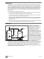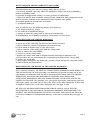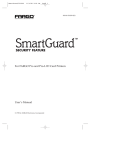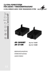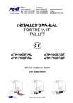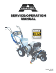
1
To the Installer:
To the Consumer:
Please attach these instructions
next to the water heater.
Please read these and all component
instructions and keep for future reference.
Storage Tanks
Instruction Manual
Warranty, Registration Card and Parts List are included.
Homeowner: Please remember to return the Registration Card!
WARNING
HANDLING
Improper installation, adjustment, alteration,
service or maintenance can cause serious
injury or property damage. Refer to this
manual. For assistance or additional
information, consult a qualified installer or
service agency.
Before uncrating, check for shipping damage.
Report any damage to your carrier. Note
damage on bill of lading or delivery receipt
and file a claim.
CAUTION
The recommended temperature for normal
residential use is 120°F. The dial on the aquastat
does not always reflect the out-coming water
temperature and it could occasionally exceed
120°F. Variation in outcoming temperature
could be based on factors including, but not
limited to, usage patterns and type of
installation. Test water at the tap nearest to
the water heater and storage tank.
WARNING
Hotter water increases the risk of scald injury.
Before adjusting the water temperature setting,
read this instruction manual. Temperatures at
which injury occurs vary with the person’s age
and the length of exposure. The slower
reaction time of children, elderly, or
physically or mentally challenged persons
increases the scalding hazard to them. It is
recommended that lower water temperatures
be used where these exposure hazards exist.
Households with small children or invalids
may require a temperature setting less than
120°F to prevent accidental contact with hot
water. To produce less than 120°F, use point-ofuse temperature limiting devices.
If higher water temperature is needed in part
of the water system, automatic temperature
limiting devices must be used on all lines to
water taps.
INSTALLER RESPONSIBILITIES
Please read all instructions before installing or
placing this storage tank into service. This
unit must be installed by licensed or
authorized installers, or technical personnel
that service water heating equipment. The
Storage Tank must be installed in accordance
with all local codes and ordinances.
#23950
LOCATION
This storage tank should be located in a
central location to the piping system, as close
as possible to the heat source and in an area
not subject to freezing temperatures. Leave
sufficient space for servicing and maintaining
the tank.
THIS MANUAL HAS BEEN PREPARED TO
ACQUAINT YOU WITH THE INSTALLATION,
OPERATION, AND MAINTENANCE OF YOUR
WATER HEATER AND TO PROVIDE IMPORTANT
SAFETY INFORMATION.
Read all instructions thoroughly before attempting installation or operation of your
water heater. Keep these instructions for future
reference.
Local plumbing and electrical codes must be
followed in the installation of this storage
tank. In the absence of a local code use the
UNIFORM PLUMBING CODE and the NFPA
Code. Local codes may supersede instructions
in this installation manual.
These instructions are a guide for the correct
installation of the storage tank. The manufacturer will not be liable for damages caused by
failure to comply with the installation and
operating instructions outlined on the
following pages.
If you lack the necessary skills required or have
difficulty following the directions, seek help
from a qualified person for that part of the
installation you do not understand.
FAILURE TO FOLLOW THESE INSTRUCTIONS
OR ALL APPLICABLE BUILDING CODES AND
REGULATIONS VOIDS THE WARRANTY ON
THIS WATER HEATER.
Rev 2 8/10
Hot Outlet
ANODE
ANODE
Aquastat
Dra
i
Va n
lve
45°
30°
ly
pp r n
Su etu
R
R
Va elie
lve f
30°
Aquastat
Dra
i
Va n
lve
45°
ANODE
ANODE
ly
pp r n
Su etu
R
R
Va elie
lve f
Hot Outlet
45°
0°
B
45°
T&P Relief Valve Conn.
0°
B
Supply/Return Conn.
T&P Relief Valve Conn.
Supply/Return Conn.
A
Aquastat Conn.
Aquastat Conn.
C
A
Supply/Return Conn.
C
Supply/Return Conn.
D
Drain Valve
Drain Valve
D
E
E
Figure 1: 30ST, 50ST
Figure 2: 80ST, 119ST
Weigh
t (lbs.)
30
3⁄4''
2''
2''
3⁄4''
391⁄2''
20''
30''
111⁄16''
43⁄16''
150
50ST
50
3⁄4''
2''
2''
3⁄4''
481⁄2''
22''
39''
111⁄16''
43⁄16''
190
80ST
80
1''
2''
2''
3⁄4''
601⁄2''
24''
50''
21''
6''
250
119ST
119
1''
2''
2''
3⁄4''
651⁄2''
28''
54''
22''
7''
385
Page 2
E
30ST
A
C
D
Dimensions
B
Aquas
tat Fit
ting
et
Hot O
utl
Suppl
y/
Retur
n Fitt
ing
ng
T&P F
itti
Storag
e Cap
acity
(ga
l.)
Table 1: ST Dimensions
Storage Tanks
Anode Rods
Hot Outlet
(2) NPT Connections
(T&P valves NOT supplied)
3/4" NPT SPUD
1" NPT SPUD
2" NPT SPUD
1" NPT SPUD
2" NPT SPUD
ASME Rating Plate
Inlet/Return
Connections
Aquastat
Connection
Cleanout Hand-hole
2" NPT SPUD
Drain Valve
Figure 4: ASME Horizontal
Figure 3: ASME Vertical
Table 2: ASME ST Dimensions
Horizontal
Vertical
Model
2”
Insulation
w/External
Jacket
Storage
(gal)
Working
Pressure
Overall
Diameter
T&P Relief
Valve
Conn.
Inlet/
Return
Conn.
Hot
Outlet
Conn.
Aquastat
Conn.
Overall
Height/
Length
Shipping
Weight
(lbs)
119ST-A-150
Standard
119
150
28Ó
1 x 1Ó NPT
2Ó
2Ó
•Ó
65!Ó
385
200ST-A-125
Standard
200
125
34Ó
2 x 1Ó NPT
2!Ó
2!Ó
•Ó
79!Ó
872
200ST-A-150
Standard
200
150
34Ó
2 x 1Ó NPT
2!Ó
2!Ó
•Ó
79!Ó
872
250ST-A-150
Standard
250
150
36Ó
2 x 1Ó NPT
2Ó
2Ó
•Ó
87Ó
950
350ST-A-150
Standard
350
150
40Ó
2 x 1Ó NPT
2Ó
2Ó
•Ó
92Ó
1,225
400ST-A-150
Standard
400
150
44Ó
2 x 1Ó NPT
2Ó
2Ó
•Ó
86Ó
1,345
1,585
500ST-A-150
Standard
500
150
48Ó
2 x 1Ó NPT
2Ó
2Ó
•Ó
88Ó
200ST-GA-M
Not Available
200
150
30Ó
2 x 1Ó NPT
2Ó
2Ó
•Ó
77Ó
735
350ST-GA-M
Not Available
350
150
36Ó
2 x 1Ó NPT
2Ó
2Ó
•Ó
88Ó
1,225
400ST-GA-M
Not Available
400
150
36Ó
2 x 1Ó NPT
2Ó
2Ó
•Ó
92Ó
1,345
500ST-GA-M
Not Available
500
150
42Ó
2 x 1Ó NPT
2Ó
2Ó
•Ó
88Ó
1,585
750ST-GA-M
Not Available
750
150
42Ó
2 x 1Ó NPT
2Ó
2Ó
•Ó
124Ó
2,375
1,000
150
48Ó
2 x 1Ó NPT
2Ó
2Ó
•Ó
138Ó
3,165
1000ST-GA-M Not Available
Storage Tanks
Page 3
WHEN YOU RECEIVE YOUR NEW STORAGE TANK
Check the new equipment to see if all components are in good condition. The T&P valves,
aquastat and immersion well are supplied by the installer.
TEMPERATURE CONTROLS
Bock storage tanks are equipped with 3⁄4'' tappings for the installation of immersion
temperature controls. Any temperature control approved for use in hot water systems is
acceptable. Bock recommends the use of a control with an adjustable differential so that the
differential can be adjusted to match that of your heat source controls. Setting the storage
tank temperature control 5° lower than the water heater temperature control is also
recommended. This is to ensure that when the storage tank calls for heat and the circulator is
turned on, the water being circulated is cool enough to cause the water heater to start. If the
burner does not start then the circulator could run for long periods of time, wasting energy.
Note: The recommended water temperature for domestic use is 120°. Higher water
temperatures can result in scalding. If higher or lower water temperatures are needed, point
of use tempering devices are recommended.
T&P VALVES
Temperature and pressure relief valves must be installed on all storage tanks by the installer.
All Bock storage tanks are also equipped with 3⁄4'' or 1'' tappings for the installation of
properly sized temperature and pressure relief valves. These are located on the side near the
top of vertical tanks and on the top surface of horizontal storage tanks. Relief valves are rated
for maximum system pressure and temperature as well as Btu input of the heating appliance.
This information is normally supplied on a metal tag attached to the end of the valve. For a
normal domestic water system maximum system pressure is 150 psi and temperature limit is
210°F. The Btu per hour rating will be listed next to the AGA or CSA logo on the tag under
the temperature and pressure data. Be certain to use a relief valve that is rated for the Btu per
hour input of the heating appliance. For example, if you are connecting a storage tank to a
water heater with a 50,000 Btu per hour input then the relief valve installed in the storage
tank must be rated for a minimum of 50,000 Btu per hour.
PIPING
Bock storage tanks are equipped with many different fitting sizes and configurations
depending on intended use. However, all storage tanks will have some common features. All
Bock storage tanks will have two or more anode rods installed through the top of the storage
tank. Bock storage tanks typically have three large tappings, normally 2 inches NPT or larger,
in the side of the tank. The exact location of these fittings will vary depending on tank
model and any special options ordered. The tapping nearest the bottom of the tank is used
as a cold water inlet and/or a connection to return water from the storage tank to the heat
source. A second tapping of similar size located higher up the side of the tank is used to
return heated water from the heat source. A hot water outlet is located on the top of the tank.
Page 4
Storage Tanks
INSTALLATION
There are many factors to consider when installing a storage tank. How will the system be
used? What are the hot water demands of the system? Why is a storage tank being installed?
Are the peak demands frequent such as a home with multiple showers or very intermittent
such as a church kitchen? The answers to these questions will help you determine what your
system should look like. The following drawings will show you some typical installations.
If your system does not fit one of these applications, remember the basic principles that are
illustrated here:
1. Hot water should exit the top of the tank.
2. If cold water enters the storage tank, it should enter through a fitting on the lower side of
the storage tank. Examples: boiler system, reverse storage system
3. A circulator suitable for use with potable water must be used to move cool water from the
storage tank to the heat source during stand-by periods.
4. The circulator will normally draw cool water out of a large fitting near the bottom on the
side of the storage tank and return it to the heat source. (The reverse storage system is an
exception to this.)
5. Heated water will return to the storage tank from the heat source to the large fitting nearer
the center of the storage tank or the large fitting near the top of the side.
DRAWING #1
Drawing #1 shows a typical
installation for a home or business
VALVE N.C.
with high peak loads such as
multiple showers in the morning.
COLD WATER
This drawing also shows an
SUPPLY
optional bypass system (N.C.
Valve) to allow the storage tank to
be isolated from the system. Cold
VALVE N.O.
water is connected to the inlet of
STORAGE
WATER
the water heater. Hot water is
TANK
HEATER
plumbed from the hot water outlet
of the water heater to the middle
CIRCULATING
RECIRCULATION
PUMP
fitting on the side of the storage
RETURN
tank. Hot water for the home will
(OPTIONAL)
be drawn off the top of the storage
AQUASTAT
tank. The lower fitting in the side
CHECK VALVE
of the storage tank is connected
to the cold water inlet or
recirculation return/drain valve fitting of the water heater with a circulator. The circulator is
controlled by the storage tank aquastat and draws cool water off the bottom of the tank and
returns it to the water heater for reheating. As a result, heated water is returned from the
water heater to raise the temperature of the storage tank. A check valve is also used to
prevent cold water entering the water heater from flowing backwards through the circulator
and diluting the hot water in the storage tank.
HOT WATER
OUT
Storage Tanks
Page 5
DRAWING #2
The reverse storage tank system,
drawing #2, is a variation on the
typical system discussed previously
and is intended for use in an
installation with only occasional
ON/OFF
SWITCH
high loads. An example of this is
CIRCULATING
PUMP
a church kitchen that serves a
pancake supper once a month. This
CHECK
VALVE
WATER
drastically reduces energy use (from
HEATER
stand-by
losses of the storage tank)
STORAGE
TANK
by allowing the storage tank to be
shut off during the times of low use.
AQUASTAT
This system brings cold water into
FOR PUMP
the bottom of the storage tank.
Water flows out the top of the
COLD IN
storage tank and into the cold water
inlet of the water heater. All hot
water for the facility flows out the
top of the water heater. A circulator is connected to the hot water outlet of the water heater
to draw hot water back into the storage tank. In times of low hot water use this pump can be
turned off by a switch or timer preventing the storage tank from being heated. A check valve
is also used as in the other systems to prevent cold water from diluting the hot water stream.
HOT OUT
DRAWING #3
Drawing #3 shows a storage tank
connected to a boiler. This system
is essentially the same as the typical
system shown in drawing #1. The
only significant difference is the
heat source. In this configuration
cold water is free to enter the
storage tank through the bottom
fitting or by flowing through the
boiler before entering the storage
tank. No check valve is used.
HOT
OUT
STORAGE
TANK
BOILER
TEMPERATURE
CONTROL
PUMP
COLD
IN
Page 6
Storage Tanks
DRAWING #4
Drawing #4 shows a typical
system with two water heaters
COLD WATER
connected in parallel
SUPPLY
supplying hot water to the
storage tank which then
supplies hot water to the
building load. Plumbing is
HOT WATER
identical to the typical system
OUT
shown in drawing #1 with the
MANIFOLDING
exception of the parallel water
MUST BE
EQUAL LENGTH
heaters. The storage tank can
also be connected to two water
CHECK
BOCK
BOCK
STORAGE
VALVE
heaters in series. This
CIRCULATING
TANK
HEATER
HEATER
PUMP
installation would look similar
to the parallel system. The
difference is that all cold water
will be fed to the first water
RECIRCULATION
heater
in the series, heated
RETURN
(OPTIONAL)
water from this heater will be
fed to the cold water inlet of
TANK
HEATERS MUST BE IDENTICAL
the second heater. Heated
THERMOSTAT
water from the second heater
would then be fed to the
storage tank. Cool water return from the storage tank should be returned to the second water
heater in the series.
MANIFOLDING
MUST BE
EQUAL LENGTH
DRAWING #5
Drawing #5 shows a Bock
storage tank piped to a water water geothermal heat pump
supplying heated water to a
radiant floor system (drawing
courtesy of Enertech Mfg).
GEO-STOR
TANK
MAINTENANCE
All Bock storage tanks are equipped with magnesium anode rods. These rods must be checked
annually and replaced when they become worn to 3⁄8-inch diameter or less to ensure long
tank life. The replacement interval will depend on water conditions. Failure to service and
replace the anodes will shorten tank life and void the tank warranty.
Flush the storage tank periodically to remove sediment. ASME tanks are typically equipped
with hand holes to aid in sediment removal.
Storage Tanks
Page 7
LIMITED WARRANTY
Bock Water Heaters, Inc.
110 S. Dickinson Street
Madison, WI 53703
Phone: 608-257-2225
WHAT DOES THIS LIMITED WARRANTY COVER?
This limited warranty applies only to the original consumer purchaser.
General Defects and Malfunctions: This warranty covers defections and malfunctions in your
new storage tank for a period of one year from the original installation date. We will repair
or replace, at our option, any defective or malfunctioning component of the storage tank.
This limited warranty will terminate if you sell or otherwise transfer the storage tank, or the
storage tank is installed at a location different from its original installation location.
Tank: We also warrant that the tank will not leak due to defective materials or workmanship
for five years from the date of original installation or from date of manufacture in the event
the Limited Warranty Registration Card was not completed and returned to manufacturer. If
the tank is leaking and we have verified that the leak is due to a defect in materials and
workmanship, we will replace the tank with a tank that is the nearest Bock model available
at the time of replacement. If a replacement tank is provided, it will remain warranted under
this section as if it were the original tank. For example, if we send you a replacement tank
under this limited warranty two years after the original installation date, then the
replacement tank will remain warranted for the remaining three years after the original
installation date.
HOW DO YOU GET SERVICE UNDER THE LIMITED WARRANTY?
In order to be eligible for service under this warranty you MUST return the warranty
registration card attached below within 30 days of purchasing the storage tank.
You must have a copy of the original sales receipt at the time you request service.
To get service under this limited warranty you should contact either the dealer or installer. If
dealer or installer is unknown you can call us Monday through Friday between the hours of 8
o’clock a.m. to 5 o’clock p.m. Central Time at the following number: 1-608-257-2225.
You can also write us at the following address:
Bock Water Heaters, Inc.
Warranty Support Group
110 S. Dickinson Street
Madison, WI 53703
We will respond not later than ten days after we have received your request for service.
Page 8
Storage Tanks
WHAT DOES THIS LIMITED WARRANTY NOT COVER?
This limited warranty does not cover storage tanks that are or were:
a. Incorrectly installed, especially where the installation violates state or local plumbing,
housing or building codes.
b. Operated at inappropriate settings, excessive pressures or temperatures.
c. Exposed to adverse local conditions and specifically sediment or lime precipitation in the
tank or corrosive elements in the atmosphere or unacceptable water quality.
d. Installed outside the United States or Canada.
e. Accidentally damaged.
Also, we will not cover the following charges, costs and losses:
a. Any freight or delivery charges.
b. Any removal or installation charges.
c. Charges to return the storage tank or part to the manufacturer.
d. Water damage, loss or damage to property, inconvenience or loss of use.
WHAT WILL VOID THE LIMITED WARRANTY?
If you do any of the following, you will void this limited warranty:
a. Fail to return the warranty registration card within 30 days.
b. Fail to retain an original copy of your sales receipt.
c. Fail to retain the actual rating plate from the storage tank.
d. Alter or remove the serial number.
e. Transfer or sell the storage tank.
f. Remove the storage tank from its original location and install it somewhere else
g. Fail to follow the care and maintenance instructions provided with the storage tank.
h. Remove the anode rods.
i. Fail to inspect and replace the anode rods (you must retain and present your paid receipts
as proof of anode rod replacement).
HOW DOES STATE LAW RELATE TO THIS LIMITED WARRANTY?
This is a limited warranty. WE MAKE NO OTHER EXPRESS WARRANTIES WITH RESPECT TO
THIS STORAGE TANK. We will not assume, nor authorize any person to assume for us any
other liability in connection with the sale or operation of this storage tank. ANY IMPLIED
WARRANTIES, INCLUDING MECHANTABILITY OR FITNESS FOR A PARTICULAR
APPLICATION, IMPOSED ON THIS SALE UNDER THE LAWS OF THE STATE OF SALE ARE
LIMITED TO ONE YEAR. This warranty gives you specific legal rights, and you may also have
other rights which vary from state to state. Some states do not allow limitations on how long
an implied warranty lasts, so the above limitation may not apply to you.
WE WILL NOT BE RESPONSIBLE FOR WATER DAMAGE, LOSS OF USE OF THE UNIT,
INCONVENIENCE, LOSS OR DAMAGE TO PERSONAL PROPERTY, WHETHER DIRECT OR
INDIRECT, AND WHETHER ARISING IN CONTACT OR TORT. Some states do not allow the
exclusion of incidental or consequential damages, so the above exclusion may not apply to
you.
Storage Tanks
Page 9
NOTES
Page 10
Storage Tanks
NOTES
Storage Tanks
Page 11
Storage Tanks
#23950