1
ZONARE
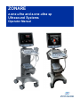
z.one ultra and z.one ultra sp
Ultrasound Systems
Operator Manual
ZONARE, the ZONARE logo and z.one ultra, and Convertible Ultrasound are all trademarks of ZONARE Medical Systems Inc. All
other trademarks are the property of their respective holders.
The z.one ultra Convertible Ultrasound™ System is covered by one or more of the following Patents:
6,251,073;6,569,102;6,618,206;6,663,567;6,685,645;6,733,455;6,773,399;6,866,631;6,866,632;6,896,658;6,936,008;
6,980,419;6,997,876;7,022,075;7,087,020;7,226,416;7,238,157;D461,814;D462,446;D467,002;D469,539;D469,877
CAUTION: United States Federal Law restricts this device to sale by or on the order of a licensed physician
or licensed veterinarian.
Part Number Q00239-00E
© 2013 by ZONARE Medical Systems Inc.
All rights reserved. Printed in the USA.
For information and pricing on ZONARE system upgrades, transducers, accessories, and new features, please call
1-877-966-2731.
Contents........................................................................................................... iii
Figures ............................................................................................................. xi
Introduction ................................................................................................... 1-1
z.one ultra Convertible Ultrasound Systems ...............................................................
z.one ultra Ultrasound Systems ..................................................................................
Intended Use ...............................................................................................................
In This Manual.............................................................................................................
1-1
1-1
1-2
1-2
The Basics: SmartCart and SmartCart sp................................................... 2-1
z.one ultra Systems: SmartCart .................................................................................. 2-1
z.one ultra Systems: SmartCart sp.............................................................................. 2-1
SmartCart/SmartCart sp Features............................................................................... 2-4
LCD Display .......................................................................................................... 2-4
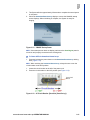
Video Level Adjustment ........................................................................................ 2-6
Microphone ........................................................................................................... 2-6
External Video Mode............................................................................................. 2-7
Control Panel ........................................................................................................ 2-7
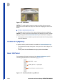
Transducer Holders .............................................................................................. 2-7
Internal Cart Hard Drive (CartHD)......................................................................... 2-7
CD/DVD Burner .................................................................................................... 2-7
Barcode Reader.................................................................................................... 2-8
Multi-Transducer Port (Option) ............................................................................. 2-8
Backup ZPak Battery (Option) .............................................................................. 2-8
Printers & Other Peripherals ................................................................................. 2-8
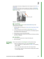
Docking/Undocking Scan Engine/Scan Module .......................................................... 2-9
Security Lock............................................................................................................... 2-9
Powering ON/OFF..................................................................................................... 2-10
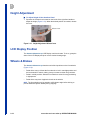
Height Adjustment ..................................................................................................... 2-12
LCD Display Position................................................................................................. 2-12
Wheels & Brakes....................................................................................................... 2-12
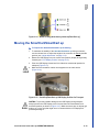
Moving the SmartCart/SmartCart sp ......................................................................... 2-13
Footswitch (Option) ................................................................................................... 2-14
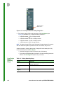
Rear I/O Panel........................................................................................................... 2-14
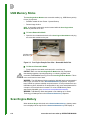
USB Memory Sticks................................................................................................... 2-15
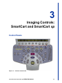
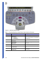
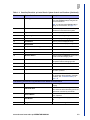
Imaging Controls: SmartCart and SmartCart sp ........................................ 3-1
Control Panels............................................................................................................. 3-1
SmartCart/SmartCart sp Keyboard ............................................................................. 3-4
z.one ultra and z.one ultra sp OPERATOR MANUAL
iii
z.one ultra and z.one ultra sp Systems
Contents
z.one ultra and z.one ultra sp Systems
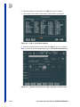
Imaging Screen............................................................................................................ 3-7
Status Icons........................................................................................................... 3-8
Non-Imaging Status............................................................................................. 3-12
SmartCart/SmartCart sp - System Navigation ........................................................... 3-14
Menu Items.......................................................................................................... 3-17
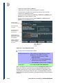
Trackball Sensitivity ................................................................................................... 3-18
Softkeys ..................................................................................................................... 3-19
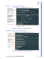
Set Time, Date, and Language .................................................................................. 3-20
Sleep and Shutdown.................................................................................................. 3-21
Password Protection .................................................................................................. 3-21
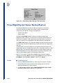
Barcode Reader (Option)........................................................................................... 3-22
Using the Barcode Reader .................................................................................. 3-22
The Basics: Scan Engine and Scan Module............................................... 4-1
Scan Engine ................................................................................................................ 4-1
Internal Archive Storage........................................................................................ 4-3
Scan Engine (Undocked) ...................................................................................... 4-3
USB Memory Sticks ..................................................................................................... 4-4
Scan Engine Battery .................................................................................................... 4-4
Checking Scan Engine Battery Charge................................................................. 4-5
Scan Engine Battery Operating Range ................................................................. 4-6
Scan Engine Battery Level Messages................................................................... 4-7
Scan Engine Battery Charger................................................................................ 4-7
AC Power Adapter ....................................................................................................... 4-9
Scan Module .............................................................................................................. 4-10
Imaging Controls: Scan Engine................................................................... 5-1
Scan Engine LCD Display ...........................................................................................
Virtual Keyboard (VKB) .........................................................................................
User Controls ...............................................................................................................
Scan Engine Control Panel ...................................................................................
System Navigation .......................................................................................................
Menu Icons............................................................................................................
Tabs ......................................................................................................................
5-1
5-2
5-3
5-3
5-5
5-7
5-7
Transducers and MTP Option ...................................................................... 6-1
ZONARE Transducers ................................................................................................. 6-1
Connecting/Disconnecting..................................................................................... 6-2
Multi-Transducer Port Option....................................................................................... 6-3
Transducer Protective Sheath ..................................................................................... 6-5
Biopsy Guide................................................................................................................ 6-5
TEE Transducer (P8-3TEE)......................................................................................... 6-6
Intended Use ......................................................................................................... 6-7
Visual Examination ................................................................................................ 6-7
General Safety ...................................................................................................... 6-8
Preparation for Use ............................................................................................... 6-8
Patient Selection ................................................................................................... 6-9
Deflection and Scan Plane Rotation Control ......................................................... 6-9
Scan Plane Indicator ........................................................................................... 6-11
Temperature Indicator ......................................................................................... 6-12
iv
z.one ultra and z.one ultra sp OPERATOR MANUAL
Examination ........................................................................................................
TEE – Care and Maintenance ...................................................................................
Inspecting Transducer ........................................................................................
Cleaning & Disinfecting TEE Transducer............................................................
TEE Transducer Cleaning and Disinfecting Solutions ........................................
Leakage Safety Testing.......................................................................................
Storing the TEE Transducer................................................................................
Transporting TEE Transducer.............................................................................
ViewFlex™ ICE Catheters (P9-3IC ICE Catheter) ....................................................
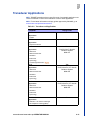
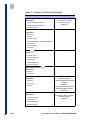
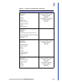
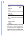
Transducer Applications ............................................................................................
6-13
6-14
6-14
6-15
6-16
6-17
6-20
6-20
6-20
6-21
Imaging .......................................................................................................... 7-1
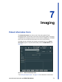
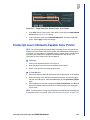
Patient Information Form............................................................................................. 7-1
Softkeys ................................................................................................................ 7-2
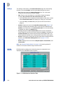
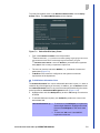
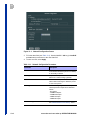
DICOM Worklist .................................................................................................... 7-2
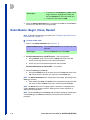
Exam Basics: Begin, Close, Restart............................................................................ 7-4
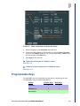
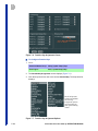
Presets ........................................................................................................................ 7-6
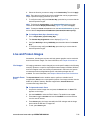
Programmable Keys.................................................................................................... 7-9
Live and Frozen Images............................................................................................. 7-11
Live Images.......................................................................................................... 7-11
Frozen Images .................................................................................................... 7-12
Clip/Image Store (Protocol Button - SmartCart only) .......................................... 7-12
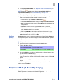
Brightness Mode (B-Mode/2D) Imaging .................................................................... 7-13
Working with B-Mode Imaging ............................................................................ 7-14
Virtual Apex Array Format................................................................................... 7-15
Dual Mode........................................................................................................... 7-16
Simultaneous Dual Mode.................................................................................... 7-17
Dual Annotations................................................................................................. 7-17
Optimize Feature ................................................................................................ 7-17
Compound Imaging............................................................................................. 7-19
Needle Viz Preset (Linear array transducers)..................................................... 7-20
B-Mode Controls ................................................................................................. 7-20
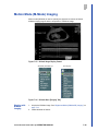
Motion Mode (M-Mode) Imaging ............................................................................... 7-29
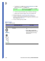
Working with M-Mode Imaging ........................................................................... 7-29
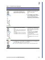
M-Mode Controls ................................................................................................ 7-30
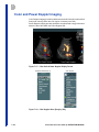
Color and Power Doppler Imaging ............................................................................ 7-34
Working with Color and Power Doppler Imaging ................................................ 7-35
Dual Imaging Mode............................................................................................. 7-36
Simultaneous Dual Mode.................................................................................... 7-36
Color Doppler and Power Doppler Controls........................................................ 7-38
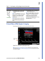
Pulsed Wave (PW) Doppler Imaging......................................................................... 7-43
Working with PW Doppler Imaging ..................................................................... 7-44
PW Doppler Controls .......................................................................................... 7-45
Duplex Mode....................................................................................................... 7-50
Triplex Mode ....................................................................................................... 7-51
Auto-Dop Trace................................................................................................... 7-51
Continuous Wave (CW) Doppler Imaging ................................................................. 7-52
CW Doppler Controls .......................................................................................... 7-53
3D & 4D (Real-Time 3D) Imaging.............................................................................. 7-55
z.one ultra and z.one ultra sp OPERATOR MANUAL
v
z.one ultra and z.one ultra sp Systems
1
z.one ultra and z.one ultra sp Systems
Postprocessing Modes ........................................................................................
3D/4D Imaging Controls ......................................................................................
Elastography ..............................................................................................................
Configure Mode/Function Key.............................................................................
Display Formats ..................................................................................................
Strain Acquisition.................................................................................................
Elastography User Controls ................................................................................
Elastography Measurements...............................................................................
Ocular Preset .............................................................................................................
Contrast Imaging .......................................................................................................
Contrast Imaging User Controls ..........................................................................
7-58
7-61
7-64
7-64
7-64
7-65
7-67
7-71
7-73
7-74
7-75
Annotations ................................................................................................... 8-1
Annotation Types ......................................................................................................... 8-1
Free-Form Text...................................................................................................... 8-1
Programmed Orientation Text (POT)..................................................................... 8-1
List Text Entries ..................................................................................................... 8-2
Arrow Graphic ....................................................................................................... 8-2
Body Pattern Graphics .......................................................................................... 8-2
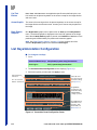
List Keys/Annotation Configuration.............................................................................. 8-2
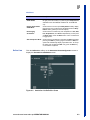
Define Lists............................................................................................................ 8-3
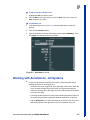
Working with Annotations - All Systems ...................................................................... 8-5
POTS and Lists ..................................................................................................... 8-6
Delete Word and Delete Text ................................................................................ 8-6
Insert Mode and Overwrite Mode .......................................................................... 8-6
Block Text Manipulation......................................................................................... 8-7
Annotation Procedures - SmartCart/SmartCart sp....................................................... 8-7
Annotation Button (SmartCart only) ...................................................................... 8-7
Annotation Procedures - Scan Engine....................................................................... 8-11
Graphics Procedures - SmartCart/SmartCart sp ....................................................... 8-13
Graphics Procedures - Scan Engine ......................................................................... 8-15
Dual Imaging Annotations - All Systems.................................................................... 8-17
Using Annotations During Dual Imaging ............................................................. 8-17
Measurements and Calculations ................................................................. 9-1
Exam Types and Measurement Menus .......................................................................
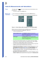
Tools for Measurements and Calculations ...................................................................
Freeze ...................................................................................................................
Measure and Calcs Menus....................................................................................
Calipers .................................................................................................................
Data Display Box (DDB) ........................................................................................
Calculation Packages ..................................................................................................
Customizing Calc Packages..................................................................................
Worksheets and Reports .............................................................................................
Data Fields ............................................................................................................
Editing Worksheets................................................................................................
Selecting Worksheet and Report Displays ............................................................
User Customizable Worksheets ..................................................................................
Setup .....................................................................................................................
Assigning User Worksheets to Presets .................................................................
vi
9-1
9-2
9-2
9-2
9-3
9-3
9-4
9-4
9-6
9-6
9-7
9-7
9-7
9-7
9-8
z.one ultra and z.one ultra sp OPERATOR MANUAL
Ending & Restoring Exams ................................................................................. 9-10
Import & Export .................................................................................................... 9-11
Backup, Restore, Rebuild & Clean Install ............................................................ 9-11
Printing Reports.......................................................................................................... 9-11
Printing OB & GYN Reports ...................................................................................... 9-13
Exporting Report Data to Serial Device..................................................................... 9-14
Generic Measurement Procedures ........................................................................... 9-15
B-Mode ............................................................................................................... 9-15
M-Mode............................................................................................................... 9-18
PW Doppler Mode............................................................................................... 9-20
OB Calculation Package ........................................................................................... 9-26
OB Worksheets and Reports .............................................................................. 9-28
OB Calculation Trending..................................................................................... 9-31
Procedures for OB Calculation Packages........................................................... 9-33
Additional Calculation Packages ............................................................................... 9-35
Abdominal Package ............................................................................................ 9-36
Gyn and Follicular Package ................................................................................ 9-38
Pediatric Hip Package......................................................................................... 9-39
Vascular Packages .................................................................................................... 9-41
Carotid Calc Package ......................................................................................... 9-41
Upper Extremity Arterial Calc Package............................................................... 9-41
Grafts Submenu Selections ................................................................................ 9-42
Lower Extremity Arterial Calc Package............................................................... 9-42
Lower Extremity Venous Calc Package .............................................................. 9-43
Upper Extremity Venous Calc Package .............................................................. 9-43
Venous Measurements ....................................................................................... 9-44
Auto-Dop Trace ......................................................................................................... 9-44
Autotrace Overview............................................................................................. 9-46
Volume Flow ....................................................................................................... 9-49
Auto Doppler Volume Flow Grafts/Shunts (Vasc Calc) ....................................... 9-50
Measurement Accuracy............................................................................................. 9-51
2D Measurement Accuracy................................................................................. 9-51
Elapsed Time or Rate Measurement Accuracy................................................... 9-52
Color Doppler Velocity Measurement Accuracy.................................................. 9-53
Velocity Accuracy in CD...................................................................................... 9-53
Registration Accuracy in CD ............................................................................... 9-54
PW Doppler Velocity Measurement Accuracy .................................................... 9-54
OB Tables Accuracy............................................................................................ 9-54
Diagnostic Calculation Accuracy......................................................................... 9-54
Numeric Display Precision .................................................................................. 9-54
Echocardiography Option .......................................................................... 10-1
Cardiac Calculation Package ....................................................................................
Cardiac Imaging and Related Functions ...................................................................
ECG ....................................................................................................................
Sweep Speed......................................................................................................
M-Mode Calculations ..........................................................................................
2D (B-Mode) Calculations...................................................................................
2D Calculations (Trace/Mark Function) ..............................................................
z.one ultra and z.one ultra sp OPERATOR MANUAL
10-1
10-5
10-5
10-7
10-8
10-8
10-9
vii
z.one ultra and z.one ultra sp Systems
1
z.one ultra and z.one ultra sp Systems
Doppler Calculations .........................................................................................
Heart Rate Measurements ................................................................................
Clip/Image Store (Protocol Button)....................................................................
Image Width Button (SmartCart only) ...............................................................
PW/CW/TDI (Pulsed Wave/Continuous Wave/Tissue Doppler Imaging) ..........
Intracardiac Echocardiography (P9-3ic ICE Catheter).............................................
10-10
10-11
10-11
10-12
10-13
10-15
Archive and Review .................................................................................... 11-1
Preparation for Archive & Review .............................................................................. 11-2
IQ Scan Data ........................................................................................................... 11-10
3D/4D Volume Data ................................................................................................. 11-11
Keyboard Keys ........................................................................................................ 11-12
SmartCart/SmartCart sp.................................................................................... 11-12
Scan Engine ...................................................................................................... 11-12
Current Exams: Review Procedures........................................................................ 11-12
Archived Exams: Review Procedures...................................................................... 11-14
SmartCart/SmartCart sp.................................................................................... 11-14
Scan Engine ...................................................................................................... 11-16
Deleting Images and Exams .................................................................................... 11-17
SmartCart/SmartCart sp.................................................................................... 11-17
Scan Engine ...................................................................................................... 11-18
Storing Archived Exams to DICOM Devices ............................................................ 11-20
Restarting an Exam ................................................................................................. 11-20
Annotations and Measurements .............................................................................. 11-21
Exporting Exams...................................................................................................... 11-21
Export Options................................................................................................... 11-23
Showcase® CD/DVD Viewer Basics ....................................................................... 11-27
Importing Exams ...................................................................................................... 11-34
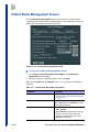
Patient Exam Management Screen ......................................................................... 11-36
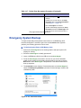
Emergency System Backup..................................................................................... 11-38
Printers and Peripherals ............................................................................ 12-1
AVED - Audio-Video Extension Device......................................................................
Status LED ..........................................................................................................
AVED Video Output .............................................................................................
Microphone Recording ........................................................................................
Sony UP-D897 Digital (USB 2.0) B&W Printer ..........................................................
Sony UP-D25MD Digital (USB) Color Printer ............................................................
Setting Up or Adding a Local (USB) Printer...............................................................
Postscript Level 3 Network-Capable Color Printer.....................................................
12-1
12-3
12-3
12-3
12-3
12-4
12-5
12-7
DICOM and FTP Connectivity .................................................................... 13-1
Network...................................................................................................................... 13-1
Wireless Network Connectivity .................................................................................. 13-3
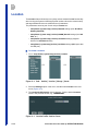
Storage Media............................................................................................................ 13-3
Location ..................................................................................................................... 13-4
DICOM Menu ............................................................................................................. 13-5
General ...................................................................................................................... 13-6
Printers ...................................................................................................................... 13-7
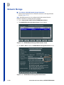
Network Storage ...................................................................................................... 13-10
viii
z.one ultra and z.one ultra sp OPERATOR MANUAL
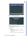
DICOM Structured Reports .....................................................................................
MPPS ......................................................................................................................
DICOM Worklist.......................................................................................................
Store/Print Buttons ..................................................................................................
FTP Storage ............................................................................................................
13-14
13-14
13-16
13-19
13-21
User Maintenance ....................................................................................... 14-1
Scan Engine Touchscreen Calibration ...................................................................... 14-2
Touchscreen Calibration Procedure ................................................................... 14-3
User Diagnostics Panel ............................................................................................. 14-3
Settings ............................................................................................................... 14-5
Maintenance ....................................................................................................... 14-5
Preset Mgmt/System Setup: Backup/Restore ........................................................... 14-6
Presets................................................................................................................ 14-6
System .............................................................................................................. 14-10
Factory Presets................................................................................................. 14-12
Software Upgrade/Installation ................................................................................. 14-14
Verifying Current System Software Revision .................................................... 14-15
System Software Installation............................................................................. 14-15
Basic System Care.................................................................................................. 14-17
SmartCart/SmartCart sp Backup ZPak Battery (optional)................................. 14-17
Checking the Battery (Scan Engine)................................................................. 14-17
Battery Charging (Scan Engine) ....................................................................... 14-18
Battery Maintenance (Scan Engine) ................................................................. 14-18
Internal Storage Media Maintenance ................................................................ 14-18
LCD Display Cleaning (SmartCart/SmartCart sp)............................................. 14-19
Transducer Maintenance......................................................................................... 14-20
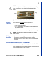
Inspecting Transducers..................................................................................... 14-21
Verifying Imaging Performance......................................................................... 14-21
Cleaning and Disinfecting Transducers................................................................... 14-21
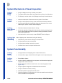
System Mechanical & Visual Inspection.................................................................. 14-22
Verifying System Display .................................................................................. 14-22
Verifying System Controls................................................................................. 14-22
Verifying Wheel & Brake Operation .................................................................. 14-22
Verifying Cable & Peripheral Connectivity ........................................................ 14-22
System Functionality ............................................................................................... 14-22
Verifying System Controls................................................................................. 14-22
Verifying System Operation .............................................................................. 14-22
Verifying Peripherals ............................................................................................... 14-23
B/W and Color Printer ....................................................................................... 14-23
Print Reports ..................................................................................................... 14-23
Shipping and Storage .............................................................................................. 14-23
Disposal ............................................................................................................ 14-24
Troubleshooting .......................................................................................... 15-1
ZONARE Contact Information ...................................................................................
Technical Support ...............................................................................................
Subsidiaries ........................................................................................................
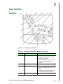
User Troubleshooting Procedures.............................................................................
Image Trouble-shooting Techniques ...................................................................
z.one ultra and z.one ultra sp OPERATOR MANUAL
15-1
15-1
15-2
15-2
15-2
ix
z.one ultra and z.one ultra sp Systems
1
z.one ultra and z.one ultra sp Systems
Acoustic Artifacts................................................................................................. 15-5
Power-ON Problems ........................................................................................... 15-7
System Start-Up Problems .................................................................................. 15-8
Peripheral Problems............................................................................................ 15-8
Printer Error Messages ....................................................................................... 15-9
Transducer Problems .......................................................................................... 15-9
General Operation Problems............................................................................... 15-9
Hardware Date of Manufacture ......................................................................... 15-10
Send Log Files to ZONARE..................................................................................... 15-10
Specifications.............................................................................................. 16-1
Component Specifications ......................................................................................... 16-1
Glossary, Abbreviations, and Body Pattern Graphics............................. 17-1
Glossary..................................................................................................................... 17-1
Abbreviations ............................................................................................................. 17-4
Body Pattern Graphics............................................................................................... 17-9
Index. . . . . . . . . . . . . . . . . . . . . . . . . . . . . . . . . . . . . . . . . . . . . . . . . . . . Index-1
x
z.one ultra and z.one ultra sp OPERATOR MANUAL
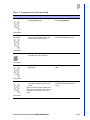
Figure 2-1.
Figure 2-2.
Figure 2-3.
Figure 2-4.
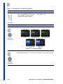
Figure 2-5.
Figure 2-6.
Figure 2-7.
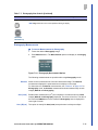
Figure 2-8.
Figure 2-9.
Figure 2-10.
Figure 2-11.
Figure 2-12.
Figure 2-13.
Figure 2-14.
Figure 2-15.
Figure 2-16.
Figure 2-17.
Figure 3-1.
Figure 3-2.
Figure 3-3.
Figure 3-4.
Figure 3-5.
Figure 3-6.
Figure 3-7.
Figure 3-8.
Figure 3-9.
Figure 3-10.
Figure 3-11.
Figure 3-12.
Figure 3-13.
Figure 4-1.
Figure 4-2.
Figure 4-3.
Figure 4-4.
Figure 4-5.
Figure 4-6.
Figure 4-7.
Figure 4-8.
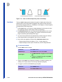
z.one ultra Convertible Ultrasound System ........................................... 2-2
z.one ultra Ultrasound System (nonconvertible).................................... 2-3
z.one ultra sp Convertible Ultrasound System ...................................... 2-3
z.one ultra sp Ultrasound System (nonconvertible)............................... 2-4
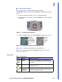
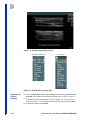
SmartCart/SmartCart sp LCD Display ................................................... 2-5
Full-Screen Image Display .................................................................... 2-5
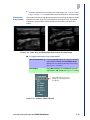
Audio/Video Configuration Screen (SmartCart Example)...................... 2-6
Docking/Undocking Scan Engine/Scan Module .................................... 2-9
SmartCart/SmartCart sp Keylock Location.......................................... 2-10
Power ON/OFF Button (SmartCart/SmartCart sp) .............................. 2-10
ZONARE Startup Screen..................................................................... 2-11
AC Circuit Breaker (SmartCart/SmartCart sp)..................................... 2-11
Height Adjustment Release Lever ....................................................... 2-12
Wheel Locking/Brake Pedal (SmartCart/SmartCart sp) ...................... 2-13
SmartCart/SmartCart sp LCD Display Position for Transport.............. 2-13
Cable Hooks ........................................................................................ 2-14
SmartCart/SmartCart sp I/O Panel ...................................................... 2-14
SmartCart Control Panel ...................................................................... 3-1
SmartCart sp Control Panel................................................................... 3-2
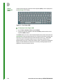
SmartCart/SmartCart sp Keyboard........................................................ 3-4
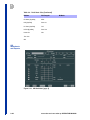
SmartCart/SmartCart sp Image Screen................................................. 3-7
Image Screen - Description of Layout ................................................... 3-8
Menu on LCD Display.......................................................................... 3-16
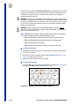
Trackball with Set Buttons ................................................................... 3-17
Trackball: Highlight and Select ON/OFF Item ..................................... 3-17
Trackball Configuration Screen ........................................................... 3-18
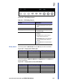
Softkey Display - Generic .................................................................... 3-19
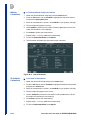
Date & Time Configuration Screen...................................................... 3-20
Access Control Screen ........................................................................ 3-21
Barcode Reader Configuration Screen................................................ 3-22
Scan Engine with Transducer (Front View) ........................................... 4-2
Scan Engine (Back View) ...................................................................... 4-2
Scan Engine Example: Rear View - Removable Media Port................. 4-4
Scan Engine Battery Slot....................................................................... 4-5
Scan Engine Onscreen Battery Charge Icon......................................... 4-6
Scan Engine Battery Charger................................................................ 4-8
AC Power Adapter................................................................................. 4-9
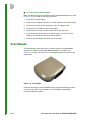
Scan Module........................................................................................ 4-10
z.one ultra and z.one ultra sp OPERATOR MANUAL
xi
z.one ultra and z.one ultra sp Systems
Figures
z.one ultra and z.one ultra sp Systems
Figure 5-1.
Figure 5-2.
Figure 5-3.
Figure 5-4.
Figure 5-5.
Figure 5-6.
Figure 5-7.
Figure 5-8.
Figure 5-9.
Figure 5-10.
Figure 6-1.
Figure 6-2.
Figure 6-3.
Figure 6-4.
Figure 6-5.
Figure 6-6.
Figure 6-7.
Figure 6-8.
Figure 6-9.
Figure 6-10.
Figure 6-11.
Figure 6-12.
Figure 6-13.
Figure 6-14.
Figure 6-15.
Figure 6-16.
Figure 6-17.
Figure 6-18.
Figure 6-19.
Figure 7-1.
Figure 7-2.
Figure 7-3.
Figure 7-4.
Figure 7-5.
Figure 7-6.
Figure 7-7.
Figure 7-8.
Figure 7-9.
Figure 7-10.
Figure 7-11.
Figure 7-12.
Figure 7-13.
Figure 7-14.
Figure 7-15.
Figure 7-16.
Figure 7-17.
Figure 7-18.
Figure 7-19.
Figure 7-20.
xii
Scan Engine LCD Display......................................................................5-1
Scan Engine VKB ..................................................................................5-2
Scan Engine Control Panel....................................................................5-3
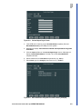
Main System Menu and Tabs - Tools Tab is Highlighted ......................5-5
Scan Engine Tools Menu.......................................................................5-6
System Setup Submenu ........................................................................5-6
Menu Items with Options and Items Below ............................................5-6
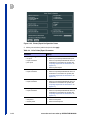
Presets Tab Menu..................................................................................5-8
Patient Tab Menu...................................................................................5-8
Tools Tab ...............................................................................................5-8
Transducer.............................................................................................6-2
Scan Engine and Transducer ................................................................6-2
Bent, Broken, or Missing Pins on Transducer........................................6-3
Multi-Transducer Port (attached to Scan Engine) ..................................6-4
MTP Transducer Softkeys .....................................................................6-4
P8-3TEE Transducer .............................................................................6-7
Tip Deflection Control Wheels .............................................................6-10
Friction Lock Operation - Right/Left .....................................................6-10
Friction Lock Operation - Anterior/Posterior.........................................6-11
Scan Plane Rotation ............................................................................6-11
Scan Plane Indicator............................................................................6-12
Temperature Indicator at 40.5°C..........................................................6-12
Temperature Indicator at 41.5°C..........................................................6-12
Temperature Warning at 41.5°C ..........................................................6-12
Temperature Indicator When Max Temp Exceeded ............................6-13
Temperature Warning When Max Temp Exceeded.............................6-13
TEE Transducer - Connector and Pins ................................................6-15
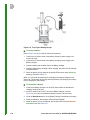
Typical Leakage Tester Setup .............................................................6-18
Leakage Tester ....................................................................................6-19
Patient Information Form .......................................................................7-1
DICOM Worklist Selection Table ...........................................................7-2
Patient Worklist Query Screen ...............................................................7-3
Enable/Disable Presets Screen .............................................................7-8
Preset Customization Configuration Screen ..........................................7-9
Function Key Assignments Screen ......................................................7-10
Function Key Assignment Options.......................................................7-10
B-Mode Image Display Format ............................................................7-14
B-Mode Menu (Imaging Tab) ...............................................................7-14
Linear Array and Virtual Apex Array Formats for Same Image............7-15
B Format: Select LIN or VA..................................................................7-15
Linear and Virtual Apex Array Icons and Softkeys...............................7-16
Imaging Configuration Screen (detail) - OPTIMIZE Button Setup .......7-18
Menu Access - Compounding Function ...............................................7-20
M-Mode Image Display Format............................................................7-29
M-Mode Menu (Imaging Tab) ..............................................................7-29
Color Mode & Power Doppler Display Format .....................................7-34
Color Doppler Menu (Imaging Tab) .....................................................7-34
Pulsed Wave (PW) Doppler Image ......................................................7-43
AutoTrace Measure Menu ...................................................................7-51
z.one ultra and z.one ultra sp OPERATOR MANUAL
Figure 7-21.
Figure 7-22.
Figure 7-23.
Figure 7-24.
Figure 7-25.
Figure 7-26.
Figure 7-27.
Figure 7-28.
Figure 7-29.
Figure 7-30.
Figure 7-31.
Figure 7-32.
Figure 7-33.
Figure 7-34.
Figure 7-35.
Figure 7-36.
Figure 7-37.
Figure 7-38.
Figure 7-39.
Figure 7-40.
Figure 8-1.
Figure 8-2.
Figure 8-3.
Figure 8-4.
Figure 8-5.
Figure 8-6.
Figure 9-1.
Figure 9-2.
Figure 9-3.
Figure 9-4.
Figure 9-5.
Figure 9-6.
Figure 9-7.
Figure 9-8.
Figure 9-9.
Figure 9-10.
Figure 9-11.
Figure 9-12.
Figure 9-13.
Figure 9-14.
Figure 9-15.
Figure 9-16.
Figure 9-17.
Figure 9-18.
Figure 9-19.
Figure 9-20.
Figure 9-21.
Figure 9-22.
Figure 9-23.
PW Autotrace Icon - Doppler Data Field ............................................. 7-52
Doppler Mode Softkey (far right on softkey panel) .............................. 7-52
3D/4D Preprocessing Softkey Display................................................. 7-56
3D Setup Mode Status Field................................................................ 7-57
3D ROI with Cut Line........................................................................... 7-57
3D Render Mode (Surface) ................................................................. 7-58
MPR Mode Display.............................................................................. 7-59
MPR Mode - Thick Slice ...................................................................... 7-60
Tomo Mode Display............................................................................. 7-60
Tomo Mode - One-Up Display with Measurements............................. 7-61
Elastography Default Image Display - Dual......................................... 7-65
Elastography Softkeys - SmartCart/SmartCart sp ............................... 7-67
Elastography Maps.............................................................................. 7-70
Elastography Measurement Options ................................................... 7-71
Area Ratio: First Trace/Ellipse - B-Mode ............................................. 7-72
Area Ratio: Second Trace/Ellipse - Elastography ............................... 7-72
Ocular Preset....................................................................................... 7-73
Ocular Imaging Screen........................................................................ 7-74
Key Assignment Screen (detail): Contrast Selection........................... 7-74
Contrast Imaging Softkeys .................................................................. 7-75
Annotation Preset Configuration Screen ............................................... 8-2
Annotation List Definition Screen .......................................................... 8-3
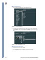
List Dropdown Box ................................................................................ 8-4
New Item Added to a List ...................................................................... 8-4
New Name for a List .............................................................................. 8-5
Annotation Softkey Display (Generic).................................................... 8-8
Generic Measurements by Mode .......................................................... 9-1
Generic Measure Menu (example); Calcs Menu (OB example)............ 9-2
Examples of Calc Menus....................................................................... 9-4
Calcs Menu............................................................................................ 9-5
Calcs – General Configuration Screen .................................................. 9-5
Example: Custom Reports Storage Destination .................................... 9-8
Select Storage Destination in Reports Box ........................................... 9-8
Custom Report Pages Screen............................................................... 9-9
User Worksheets Assigned to Cardiac Presets (Example) ................... 9-9
Printer/Export Configuration Screen.................................................... 9-12
Serial Port Settings Screen ................................................................. 9-14
Calculations Menu ............................................................................... 9-26
OB Worksheet (page 1)....................................................................... 9-28
OB Worksheet (page 2)....................................................................... 9-29
OB Worksheet (page 3)....................................................................... 9-29
OB Worksheet (page 4)....................................................................... 9-30
OB Worksheet (page 5)....................................................................... 9-30
OB Report............................................................................................ 9-31
OB Worksheet - Trending Page .......................................................... 9-32
OB Trending - Graph Screen............................................................... 9-32
Vascular Calcs Page 8 ........................................................................ 9-44
Auto-Dop Trace Configuration Screen ................................................ 9-45
Auto Params Measure Menu............................................................... 9-47
z.one ultra and z.one ultra sp OPERATOR MANUAL
xiii
z.one ultra and z.one ultra sp Systems
1
z.one ultra and z.one ultra sp Systems
Figure 9-24.
Figure 9-25.
Figure 9-26.
Figure 10-1.
Figure 10-2.
Figure 10-3.
Figure 10-4.
Figure 10-5.
Figure 10-6.
Figure 10-7.
Figure 10-8.
Figure 10-9.
Figure 10-10.
Figure 10-11.
Figure 10-12.
Figure 10-13.
Figure 10-14.
Figure 10-15.
Figure 10-16.
Figure 10-17.
Figure 10-18.
Figure 10-19.
Figure 11-1.
Figure 11-2.
Figure 11-3.
Figure 11-4.
Figure 11-5.
Figure 11-6.
Figure 11-7.
Figure 11-8.
Figure 11-9.
Figure 11-10.
Figure 11-11.
Figure 11-12.
Figure 11-13.
Figure 11-14.
Figure 11-15.
Figure 11-16.
Figure 11-17.
Figure 11-18.
Figure 11-19.
Figure 11-20.
Figure 12-1.
Figure 12-2.
Figure 12-3.
Figure 12-4.
Figure 12-5.
xiv
Auto-Dop Trace - Automeasure (Single Cycle)....................................9-49
Auto-Dop Trace - Automeasure (Multiple Cycles) ...............................9-49
Calc Menu and Graft Vol Flow Submenu.............................................9-50
Cardiac Configuration Screen..............................................................10-1
Page 2: Cardiac Measurements ..........................................................10-2
Patient Information Form: Height & Weight for Cardiac Exam.............10-2
ECG Key on SmartCart QWERTY Keyboard ......................................10-6
ECG Softkey Controls..........................................................................10-7
Sweep Speed: B-Mode (2D) ................................................................10-7
Sweep Speeds: M, CW, and PW Modes .............................................10-7
Cardiac Worksheet ..............................................................................10-8
Cardiac Worksheet: Aorta, LV .............................................................10-9
Cardiac Worksheet: LV Function, LA Volume....................................10-10
Cardiac Worksheet: Doppler..............................................................10-11
B-Mode: Full Sector Size (left); After Pressing Image Width Button (right)
10-12
Color Doppler: Full Sector Size (left); After Pressing Image Width Button
(right)10-12
Doppler Mode Softkey (far right on SmartCart softkey panel) ...........10-13
Location of Doppler Data Field ..........................................................10-13
PW Doppler - Doppler Data Field & Legend ......................................10-14
TDI - Doppler Data Field & Legend....................................................10-14
CW Doppler - Doppler Data Field & Legend ......................................10-15
Aux CW Doppler - Doppler Data Field & Legend...............................10-15
Storage Media Screen .........................................................................11-2
Storage Media Screen - detail .............................................................11-4
Exam Export Options Screen...............................................................11-4
Image Store/Print Buttons Screen .......................................................11-6
Image Store/Print Button Screen (detail) - Live Capture Still...............11-9
Scan Engine Tools Tab - View Current and Submenu ......................11-13
Archive Exam Selection Table ...........................................................11-14
Archive Exam Selection Table Pull-Down Menu................................11-15
Archive Exam Export Screen .............................................................11-22
Archive Exam Export Options Screen................................................11-24
Key Icon .............................................................................................11-26
Directories Screen .............................................................................11-28
Display of Images/Clips from a Study (Series Screen) ......................11-28
Enlarged Image/Clip Screen ..............................................................11-31
Export Images Screen .......................................................................11-33
Choose Compressor Screen..............................................................11-33
Compressor Options Drop-Down Box................................................11-34
Archive Exam Import Screen .............................................................11-35
Patient Exam Management Screen ...................................................11-36
User Break Screen.............................................................................11-38
AVED (Audio-Video Extension Device) ...............................................12-2
AVED I/O Panel ...................................................................................12-2
Sony UP-D897 B&W USB Printer........................................................12-3
Sony UP-D25MD Digital (USB 2.0) Color Printer ................................12-4
Printer Screen ......................................................................................12-6
z.one ultra and z.one ultra sp OPERATOR MANUAL
Figure 12-6.
Figure 12-7.
Figure 13-1.
Figure 13-2.
Figure 13-3.
Figure 13-4.
Figure 13-5.
Figure 13-6.
Figure 13-7.
Figure 13-8.
Figure 13-9.
Figure 13-10.
Figure 13-11.
Figure 13-12.
Figure 13-13.
Figure 13-14.
Figure 13-15.
Figure 13-16.
Figure 13-17.
Figure 13-18.
Figure 14-1.
Figure 14-2.
Figure 14-3.
Figure 14-4.
Figure 14-5.
Figure 14-6.
Figure 14-7.
Figure 14-8.
Figure 14-9.
Figure 14-10.
Figure 14-11.
Figure 14-12.
Figure 14-13.
Figure 14-14.
Figure 14-15.
Figure 14-16.
Figure 14-17.
Figure 14-18.
Figure 14-19.
Figure 14-20.
Figure 14-21.
Figure 14-22.
Figure 14-23.
Figure 14-24.
Figure 14-25.
Figure 14-26.
Figure 14-27.
Figure 14-28.
Figure 14-29.
Printer Setup Screen: Local/USB ........................................................ 12-6
Image Store/Print Buttons Screen: Print Section................................. 12-7
Network Configuration Screen............................................................. 13-2
Path: Archive | Location | Manage | Create ....................................... 13-4
Location Profile Creation Screen......................................................... 13-4
Location Menu Item and Submenu with New Location Listed............. 13-5
Location Name in Current Exam Area of Imaging Screen................... 13-5
DICOM Menu....................................................................................... 13-5
Ethernet Connection Icon .................................................................... 13-6
DICOM General Configuration Screen ................................................ 13-6
Printer Administration Screen.............................................................. 13-8
Printer Screen...................................................................................... 13-8
DICOM Network Storage Administration Screen............................... 13-10
DICOM Network Storage Destination Screen ................................... 13-10
DICOM MPPS Administration Screen ............................................... 13-15
DICOM MPPS Destination Screen .................................................... 13-15
DICOM Modality Worklist Administration Screen .............................. 13-17
DICOM Modality Worklist Server Screen .......................................... 13-17
FTP Storage Administration Screen .................................................. 13-21
FTP Storage Destination Screen....................................................... 13-21
Touchscreen Calibration Screen ......................................................... 14-3
User Diagnostics Panel ....................................................................... 14-4
User Diagnostics Panel | Settings Screen........................................... 14-5
User Diagnostics Panel | Maintenance Screen ................................... 14-5
ZPak Battery Status Message; Click OK to close................................ 14-6
Setup Button Menu.............................................................................. 14-7
Preset Admin Menu ............................................................................. 14-7
Overwrite Prompt................................................................................. 14-7
USB Prompt......................................................................................... 14-7
Restore Presets Menu......................................................................... 14-8
Presets Restore Configuration Screen ................................................ 14-8
Confirmation Prompt............................................................................ 14-8
Preset Restore Prompt ........................................................................ 14-9
Restore Presets | Exam Type Screen ................................................. 14-9
Overwrite Prompt................................................................................. 14-9
Restore Presets | Single Preset Screen ............................................ 14-10
Overwrite Prompt............................................................................... 14-10
Backup Configuration Screen............................................................ 14-11
Confirmation Prompt.......................................................................... 14-11
System Restore Configuration Screen .............................................. 14-12
Overwrite Confirmation...................................................................... 14-12
Restore Factory Menu ....................................................................... 14-13
Confirmation Screen.......................................................................... 14-13
Preset Settings On/Off Screen .......................................................... 14-13
Confirmation Screen.......................................................................... 14-13
Preset Settings On/Off Screen .......................................................... 14-14
Confirmation Screen.......................................................................... 14-14
Scan Engine Power Button................................................................ 14-15
Insert Removable Media.................................................................... 14-16
z.one ultra and z.one ultra sp OPERATOR MANUAL
xv
z.one ultra and z.one ultra sp Systems
1
z.one ultra and z.one ultra sp Systems
Figure 14-30. Bent, Broken, or Missing Pins on Transducer....................................14-21
Figure 15-1. User Log Information Screen .............................................................15-10
xvi
z.one ultra and z.one ultra sp OPERATOR MANUAL
1
1
Introduction
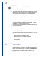
z.one ultra Convertible Ultrasound Systems
The ZONARE z.one ultra and z.one ultra sp Convertible Ultrasound™ Systems
are the world’s first convertible ultrasound systems, incorporating a full-featured
ultrasound cart and a portable Scan Engine into one system. This configuration
gives the clinician the flexibility to acquire the same premium-quality ultrasound
images on a conventional cart-based system or a small compact unit, depending
on the requirements of the clinical workflow.
• The z.one ultra Convertible Ultrasound™ System is the combination of the
SmartCart with the Scan Engine connected to the docking deck.
• The z.one ultra sp Convertible Ultrasound™ System is the combination of
the SmartCart sp with the Scan Engine connected to the docking deck.
z.one ultra Ultrasound Systems
The z.one ultra ultrasound systems (nonconvertible) comprise the new z.one
ultra Scan Module mounted on a SmartCart or SmartCart sp.
• The z.one ultra Ultrasound™ System is the combination of the SmartCart
with the Scan Module connected to the docking deck.
• The z.one ultra sp Ultrasound™ System is the combination of the
SmartCart sp with the Scan Module connected to the docking deck.
NOTE: For information and pricing on ZONARE system upgrades, transducers,
accessories, and new features, please call 1-877-966-2731, ext. 3.
z.one ultra and z.one ultra sp OPERATOR MANUAL
1-1
1
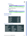
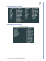
Intended Use
The SmartCart/SmartCart sp Workstations are intended to be used for the
following types of ultrasound examinations:
•
•
•
Fetal
Abdominal
Intraoperative
•
•
Pediatric
•
Neonatal/adult
•
cephalic
Pelvic
•
Vascular
Equine Endorectal
•
•
•
•
•
•
•
•
•
OB/GYN
Transvaginal
Transcranial
•
Cardiac
Transesophageal
Echocardiography
Intracardiac
Echocardio-graphy
(ICE)
Ocular
Contrast Imaging
Elastography
•
•
•
•
Small organ/parts (including
breast/testes, thyroid, etc.)
Transesophageal (TEE)
transducer
Musculoskeletal (superficial
musculoskeletal and
peripheral vascular
applications)
3D
4D (realtime 3D)
WARNING: To avoid injury to the patient, use only the Ocular Preset when
performing imaging through the eye. The FDA has established lower acoustic
energy limits for ophthalmic use. The system will not exceed these limits only if
the Ocular Preset is selected. See the Safety Manual for information about the
lower acoustic energy limits established for ophthalmic use.
CAUTION: Cardiac rhythm disturbances during perfusion studies using gas
ultrasound contrast agents have been observed in the diagnostic range of MI
values. See the specific package insert for the contrast agent being used for
details.
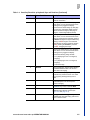
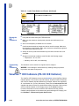
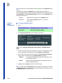
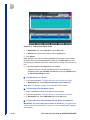
In This Manual
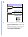
]
Chapter
1-2
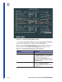
Overview
1
Introduction
Brief introduction to ZONARE z.one ultra
systems.
2
The Basics: SmartCart and
SmartCart sp Workstations
Describes the hardware and its setup for
these workstations.
3
Imaging Controls: SmartCart
and SmartCart sp
Describes the imaging controls for these
Carts and how to use.
4
The Basics: Scan Engine and
Scan Module
Describes the hardware and its setup for
these components.
5
Imaging Controls: Scan Engine Describes the imaging controls for the Scan
Engine and how to use.
6
Transducers and MTP Option
Describes ZONARE transducers, MTP
option, and how to use.
z.one ultra and z.one ultra sp OPERATOR MANUAL
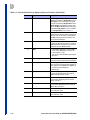
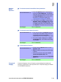
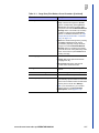
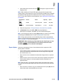
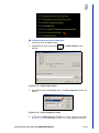
Chapter
Overview
7
Imaging
Describes procedures for all imaging
modes.
8
Annotations
Describes how to place annotations and
graphics on scan images.
9
Measurements and
Calculations
Describes the measurements and
calculations that can be performed on live
and frozen images.
10 Echocardiography Option
For z.one ultra SmartCart only: Describes
the cardiac calculation package and the
basics of cardiac imaging.
11 Archive and Review
Describes the tools and procedures for
archive and review.
12 Peripherals
Describes the ZONARE-approved
peripherals.
13 DICOM and FTP Connectivity
Describes how to set up DICOM for
ZONARE systems.
14 User Maintenance
Describes user maintenance procedures.
15 Troubleshooting
Describes troubleshooting procedures for
common problems.
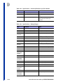
16 Specifications
Lists the technical specifications for
ZONARE systems.
17 Glossary, Abbreviations, and
Body Markers
Describes the technical terms and
abbreviations used in this manual; provides
list of Body Markers and their associated
Exam Types.
z.one ultra and z.one ultra sp OPERATOR MANUAL
1-3
1
This page intentionally blank
2
2
The Basics:
SmartCart and SmartCart sp
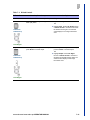
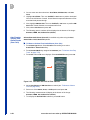
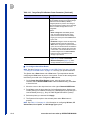
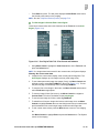
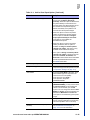
z.one ultra Systems: SmartCart
■
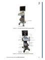
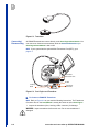
The z.one ultra Convertible Ultrasound™ System is the combination of the
SmartCart with the Scan Engine connected to the docking deck (Figure 2-1).
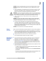
■
The z.one ultra Ultrasound™ System is the combination of the SmartCart with
the Scan Module connected to the docking deck (Figure 2-2).
z.one ultra Systems: SmartCart sp
■
The z.one ultra sp Convertible Ultrasound™ System is the combination of the
SmartCart sp with the Scan Engine connected to the docking deck
(Figure 2-3).
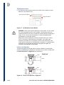
■
The z.one ultra sp Ultrasound™ System is the combination of the SmartCart
sp with the Scan Module connected to the docking deck (Figure 2-4).
z.one ultra and z.one ultra sp OPERATOR MANUAL
2-1
2
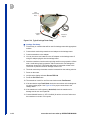
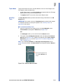
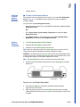
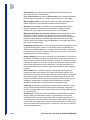
19” LCD Display
Microphone
Speakers
Gel Bottleholder
Cable Management
Hooks
Control Panel Height
Adjust
Scan Engine
Docking Deck
Power On/Off Button
Scan Engine Eject
Button
Scan Engine Lock
CD/DVD Drive
MTP Multi-Transducer
Port (option)
Printer in Printer Bay
Aux CW Port (w/ CW Doppler
option only)
ECG Port (w/ CW
Doppler option only)
Front Wheels with 3
Swivel/Lock positions
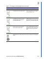
SmartCart Workstation
.
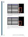
Figure 2-1. z.one ultra Convertible Ultrasound System
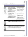
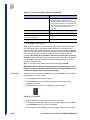
2-2
z.one ultra and z.one ultra sp OPERATOR MANUAL
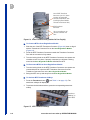
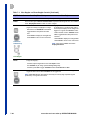
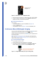
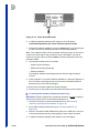
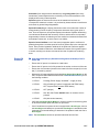
Scan Module
SmartCart Workstation
Figure 2-2. z.one ultra Ultrasound System (nonconvertible)
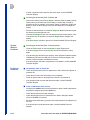
SmartCart sp
Workstation
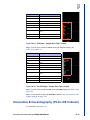
Figure 2-3. z.one ultra sp Convertible Ultrasound System
z.one ultra and z.one ultra sp OPERATOR MANUAL
2-3
2
2
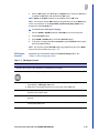
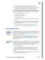
Scan Module
SmartCart sp Workstation
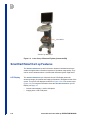
Figure 2-4. z.one ultra sp Ultrasound System (nonconvertible)
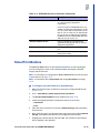
SmartCart/SmartCart sp Features
The SmartCart/SmartCart sp are full-function ultrasound workstations that are
smaller and lighter than conventional systems of equivalent image quality. They
can be used in situations where a conventional ultrasound system might not fit.
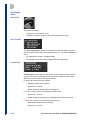
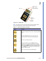
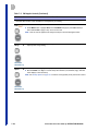
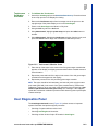
LCD Display
2-4
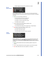
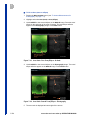
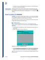
The SmartCart/SmartCart sp’s full-sized 19-inch LCD Display shows the
ultrasound image, plus patient and imaging information in designated areas of the
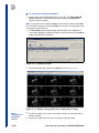
screen. The screen can displayed as shown in Figure 2-5 or in full-screen mode
(Figure 2-6). For complete information about the SmartCart/SmartCart sp LCD
Display, see page 3-7.
•
Overall screen display = 1280 x 1024 pixels
•
Imaging area = 800 x 600 pixels
z.one ultra and z.one ultra sp OPERATOR MANUAL
Figure 2-5. SmartCart/SmartCart sp LCD Display
Full Screen
Image Display
The SmartCart/SmartCart sp allows you to enlarge the imaging portion of the
monitor to use the full (1280 x 1024) display. You can easily go from the imaging
portion display of (800 x 600) to (1280 x 1024) with the push of a Function Key
(see “Programmable Keys” on page 7-9).
Figure 2-6. Full-Screen Image Display
z.one ultra and z.one ultra sp OPERATOR MANUAL
2-5
2
2
Video Level
Adjustment
All adjustments are performed from an onscreen setup menu. Available
adjustments and suggested starting settings:
■
Color Temperature
• Red:
• Green:
• Blue:
■
Brightness:
■
Contrast:
102
98
125
215
62
To Adjust LCD Display Video Settings
1. Select Setup button | System Setup | Display | Audio/Video to access the
Audio/Video Configuration screen (Figure 2-7).
Figure 2-7. Audio/Video Configuration Screen (SmartCart Example)
2. Using the Trackball, place the cursor arrow to the desired position on the
sliding bar scale (of the desired display control). Press the Set button to mark
the setting.
3. Repeat the steps above for any additional display settings that are desired for
change.
4. To save the new settings and exit, select Apply.
5. Visually inspect the output of the LCD Display to confirm the desired video
levels are achieved. Repeat the above steps, if required.
Microphone
2-6
See “Programmable Keys” on page 7-9 for setting up a Function key for the
microphone.
z.one ultra and z.one ultra sp OPERATOR MANUAL
External Video
Mode
The external digital video output, which is produced on the HDMI (DVI) video
connector at the rear panel of the SmartCart/SmartCart sp (Figure 2-17), can be
configured in the Audio/Video Configuration screen (Figure 2-7) for one of two
modes (formats):
■
Standard: 1280 x 1024 (includes image area, reference images, scheduling,
etc.)
If selected for System Display, the image area, system icons, reference
images, etc, will be displayed while scanning.
• If selected for External Video Mode, the image area, system icons,
reference images, etc, will be displayed when connected to an HDMI (DVI)
video connector.
■
Image Only: 800 x 600 (imaging area only)
If selected for System Display, only the image area will be displayed while
scanning.
• If selected for External Video Mode, only the image area will be displayed
when connected to an HDMI (DVI) video connector.
Select the desired format that is compatible with the external device being
connected to the HDMI port on the SmartCart/SmartCart sp.
Control Panel
The SmartCart/SmartCart sp has a full-featured Control Panel/User Interface (see
page 3-1).
Transducer
Holders
Safe storage for ZONARE transducers is provided on both sides of the SmartCart/
SmartCart sp (Figure 2-16).
Internal Cart
Hard Drive
(CartHD)
All current exam images are initially captured and archived to the Scan Engine’s
hard drive. This data can be automatically saved to the SmartCart/SmartCart sp
internal hard drive (CartHD) (see “To Automatically Store to Cart HD” on
page 11-4) or transferred via the Export function or retrieved from the drive via
the Import function. The size of the internal hard drive will not be less than 160
GB.
NOTE: The SmartCart/SmartCart sp internal hard drive is not intended to be used
as a long-term archive. All exam and other data on the hard drive should be
backed up regularly. See “Exporting Exams” on page 11-21, “Importing Exams” on
page 11-34, and “Presets” on page 14-6 for more information.
CD/DVD
Burner
The built-in CD/DVD burner allows users to import/export exams from the Scan
Engine's hard drive or from the CartHD (see “To Export Exams to SmartCart/
SmartCart sp Built-in CD/DVD Drive” on page 11-22 for more information).
NOTE: Wide variability in CD and DVD quality may prevent the system from
reliably writing to and reading from some commercially available discs. ZONARE
has tested the CD and DVD in the table below and currently recommends their
use. For up-to-date CD/DVD recommendations, go to: www.zonare.com/products/
accessories.
z.one ultra and z.one ultra sp OPERATOR MANUAL
2-7
2
2
Manufacturer
CD-R
Maxell
DVD+R
Taiyo Yuden
Part No.
Media
Capacity
Speed
648200
100 Pack Spindle
700 MB
48X (Max)
DVD+ZZ100SB16
YUDEN000T03
4.7 GB
16X (Max)
IMPORTANT: Before deleting any Exam data from the Scan Engine or Cart
hard drive, always verify that data was successfully transferred to the
CD/DVD by viewing it on an external reader/player.
When exams are exported onto the CD/DVD, a DICOM viewer program
(Showcase®) is simultaneously exported onto the CD/DVD, allowing the exams to
be opened, annotated, and saved in several formats on any commercial PC (see
“Showcase® CD/DVD Viewer Basics” on page 11-27).
IMPORTANT: You must install system software as described in “To Install System
Software (SmartCart/SmartCart sp)” on page 14-16 for the Showcase® viewer
program to work properly.
Barcode
Reader
You can enter patient ID numbers or accession numbers via a selection of
ZONARE-approved barcode readers that can connect to a system USB port
(Figure 2-17). See “Barcode Reader (Option)” on page 3-22.
Multi-Transduc
er Port
(Option)
The optional Multi-Transducer Port (MTP) allows simultaneous connection to the
system of up to three transducers. The user can easily activate any of the
transducers connected to the cart. For more information about the MTP and its
use, see Chapter 6.
Backup ZPak
Battery
(Option)
The SmartCart/SmartCart sp may be ordered with an optional ZPak battery that
can power each cart for up to 2 hours. The battery allows the System to be
operated in normal use without connection to an active AC power outlet.
The battery is mounted at the base of the SmartCart/SmartCart sp and is
automatically kept charged by the DC power supplies within the System. The
battery is charged (as needed) whenever the SmartCart/SmartCart sp is
connected to active AC power.
NOTE: If the ZPak battery is used, two status icons display on the SmartCart/
SmartCart sp LCD monitor: One for the ZPak battery and the other for the Scan
Engine internal battery. See Table 3-3 on page 3-8. The ZPak battery charging
status is also displayed onscreen (see Figure 3-4 on page 3-7).
Printers &
Other
Peripherals
2-8
ZONARE offers a number of optional medical grade (IEC 60601 compliant)
peripherals. Basic information on SmartCart/SmartCart sp peripherals can be
found in Chapter 12, of this manual. Detailed instruction for proper use is covered
in the manufacturer’s instructions provided at the time of shipment.
z.one ultra and z.one ultra sp OPERATOR MANUAL
Docking/Undocking Scan Engine/Scan Module
The Scan Engine/Scan Module must be docked on the SmartCart/SmartCart sp
for the cart to work.
NOTE: All imaging functions are available on the Scan Engine when it is
undocked.
To Dock Scan Engine/Module on SmartCart/SmartCart sp
1. Place the Scan Engine/Scan Module in the molded area on the docking deck
so that it aligns itself in the cradle.
2. Gently pull the Scan Engine/Scan Module towards you until you hear the
release lever click, securing the unit in place.
Figure 2-8. Docking/Undocking Scan Engine/Scan Module
To Undock Scan Engine/Module from SmartCart/SmartCart sp
NOTE: If Scan Engine/Scan Module is connected to an MTP, disconnect the MTP
before undocking (see “To Disconnect MTP from Scan Engine/Scan Module” on
page 6-4).
1. Push and hold the Scan Engine/Scan Module release lever away from you
(Figure 2-8).
2. Then slide the Scan Engine/Scan Module away from you to undock it from the
SmartCart/SmartCart sp.
Security Lock
The keylock enables/disables the removal of the Scan Engine/Scan Module from
the SmartCart/SmartCart sp docking deck.
z.one ultra and z.one ultra sp OPERATOR MANUAL
2-9
2
2
SmartCart/SmartCart sp
Keylock on Docking Deck
Figure 2-9. SmartCart/SmartCart sp Keylock Location
Powering ON/OFF
Please read and understand “Warnings - SmartCart/SmartCart sp” in the Safety
Manual before powering on the SmartCart/SmartCart sp.
The SmartCart/SmartCart sp can be powered by AC or an optional ZPak battery
that is mounted at the base of the cart. A fully charged ZPak battery allows the
SmartCart/SmartCart sp to run for up to 2 hours.
•
When the Scan Engine is docked on the SmartCart/SmartCart sp, the Scan
Engine’s internal battery will charge whether the SmartCart/SmartCart sp is
AC-powered or running off the ZPak battery.
•
If the SmartCart/SmartCart sp is running off the ZPak battery, the battery will
drain faster if it also needs to charge the Scan Engine battery.
NOTE: If the optional ZPak battery is used, two status icons display on the
SmartCart/SmartCart sp LCD monitor: One for the ZPak battery and the other for
the Scan Engine internal battery. See Table 3-3 on page 3-8.
To Power ON the SmartCart/SmartCart sp
1. Locate the power button on the front/left of the docking deck. Press and
release the ON/OFF button to turn on the System (see Figure 2-10).
NOTE: If the Scan Engine is already powered ON when docked on the SmartCart/
SmartCart sp, press the SmartCart/SmartCart sp power button to activate and
power the 19” LCD Display.
Figure 2-10. Power ON/OFF Button (SmartCart/SmartCart sp)
2-10
z.one ultra and z.one ultra sp OPERATOR MANUAL
2. The System will take approximately 30 seconds to complete the normal power
on sequence.
3. Check the SmartCart/SmartCart sp display to ensure the ZONARE startup
screen displays. When initializing is complete, the System is ready for
imaging.
Figure 2-11. ZONARE Startup Screen
NOTE: If the startup screen does not display, make sure the Scan Engine power is
turned on and properly connected to the docking deck.
To Power OFF the SmartCart/SmartCart sp
1. Press and release the power button on the SmartCart/SmartCart sp docking
deck (Figure 2-10).
NOTE: When servicing the SmartCart/SmartCart sp, always be sure to turn the
circuit breaker to the OFF position.
1. Locate the circuit breaker to the left of the power cord.
2. Press the circuit breaker to the OFF position (see Figure 2-12).
Power Cord
Outlet
Figure 2-12. AC Circuit Breaker (SmartCart/SmartCart sp)
z.one ultra and z.one ultra sp OPERATOR MANUAL
2-11
2
2
Height Adjustment
To Adjust Height of User Interface Panel
1. Squeeze the release lever located on the inside of the right-front handle to
adjust the height (Figure 2-13). When the desired position is reached, release
the lever.
Release Lever
Figure 2-13. Height Adjustment Release Lever
LCD Display Position
The SmartCart/SmartCart sp LCD Display can tilt and rotate. To do so, grasp the
sides of the LCD Display and pivot it to the desired viewing angle.
Wheels & Brakes
The SmartCart/SmartCart sp has three swivel/lock positions on the front wheels
(Figure 2-14):
•
Pedal all the way up: Allows the front wheels to lock in a straight position and
the back wheels to swivel, making it easy to maneuver down long corridors.
•
Pedal in middle position: Allows all four wheels to swivel for easy positioning
in tight spaces.
•
Pedal all the way down: Applies the brake to the wheels.
NOTE: The front wheels may be rotated to a 90-degree angle before locking to
provide additional System stability during shipping.
2-12
z.one ultra and z.one ultra sp OPERATOR MANUAL
Figure 2-14. Wheel Locking/Brake Pedal (SmartCart/SmartCart sp)
Moving the SmartCart/SmartCart sp
To Prepare the SmartCart/SmartCart sp for Moving
1. To maximize the stability of the SmartCart/SmartCart sp during movement,
use the release lever to adjust the height of the console to its lowest possible
position (see “Height Adjustment” on page 2-12).
2. Rotate the LCD Display arm to its center-most position (display facing directly
forward) (see “LCD Display Position” on page 2-12).
3. Pivot the LCD Display forward until it is folded into a horizontal position for
transport (Figure 2-15).
4. Make sure the transducer cables are wrapped over the cable hooks
(Figure 2-16).
Figure 2-15. SmartCart/SmartCart sp LCD Display Position for Transport
CAUTION: To prevent possible damage to the LCD Display during transport,
always position the LCD Display to the front and then fold it downward into a
horizontal position (as shown in Figure 2-15). Make sure there are no objects (gel
bottles, etc.) in the way that might come in contact with the LCD Display and
potentially damage it.
z.one ultra and z.one ultra sp OPERATOR MANUAL
2-13
2
2
Figure 2-16. Cable Hooks
CAUTION: To avoid possible damage to transducer cables during movement,
wrap them over the cable hooks to prevent them from wrapping around the cart
wheels.
To Move SmartCart/SmartCart sp
1. Push the cart from the front of the system (unless moving over obstacles).
CAUTION: To ensure maximum maneuverability and stability (to prevent potential
tipping), always push the SmartCart/SmartCart sp from the front of the system.
2. If moving the cart over obstacles, pull the cart from the front. Do not push the
cart over obstacles.
Footswitch (Option)
An optional remote 2-pedal footswitch is available for SmartCart/SmartCart sp.
•
The footswitch connects to the System via any one of the free USB ports on
the Cart.
•
The left pedal activates Freeze and the right pedal activates Store.
Rear I/O Panel
The input/output (I/O) panel on the rear of the SmartCart/SmartCart sp is for
connecting peripheral devices and networking (Figure 2-17).
HDMI (DVI) - output
4 USB (2.0) Ports - input/output
RJ-45 (Ethernet) network connector
Figure 2-17. SmartCart/SmartCart sp I/O Panel
2-14
z.one ultra and z.one ultra sp OPERATOR MANUAL
USB Memory Sticks
The SmartCart/SmartCart sp uses removable media (e.g., USB Memory Sticks)
for two (2) purposes:
•
Software Installer & User Preset - System Backup
•
Patient Image Archive
NOTE: A USB Memory Stick can be inserted while the SmartCart/SmartCart sp is
powered ON or OFF.
To Insert a USB Memory Stick
When a USB Memory Stick is plugged into a USB port, a status icon is displayed
on the top left of the SmartCart/SmartCart sp imaging screen (see Table 3-3 on
page 3-8).
•
Plug the USB Memory Stick into any available USB port (see Figure 2-17).
Make sure the Stick is correctly oriented for the port.
To Remove a USB Memory Stick
•
Firmly grasp the USB Memory Stick and pull it out all the way.
CAUTION: Make sure the SmartCart/SmartCart sp has fully completed
downloading upgrades, importing/exporting, or collecting log data to the USB
Memory Stick before removing it from the SmartCart/SmartCart sp. Failure to do
so will result in loss of data.
WARNING: The USB Memory Sticks supplied by ZONARE are the recommended
brand, type, and sizes for use in SmartCart/SmartCart sp Systems. They have
been verified for optimum reliability and performance. If users purchase their own
USB Memory Stick, ZONARE is not responsible for any errors associated with file
corruption or file-transfer time increases. For a list of USB Memory Sticks
approved by ZONARE, go to www.zonare.com/products/accessories.
WARNING: USB Memory Sticks designated on the labeling as U3 Smart
Technology will not operate on SmartCart/SmartCart sp Systems.
z.one ultra and z.one ultra sp OPERATOR MANUAL
2-15
2
This page intentionally blank
3
3
Imaging Controls:
SmartCart and SmartCart sp
Control Panels
31
3
2
4
28
31
31
29
6
7
9
8
11
1
27
30
5
17
18
19
10
14
16
21
13
22
24
26
25
12
20
15
15
23
Figure 3-1. SmartCart Control Panel
z.one ultra and z.one ultra sp OPERATOR MANUAL
3-1
3
24
1
3
2
6
5
4
8
7
10
17
22
21
9
14
18
11
13
19
16
20
12
15
15
23
23
Figure 3-2. SmartCart sp Control Panel
Table 3-1. SmartCart/SmartCart sp Control Panels: System Controls and Functions
Number
System Control
Description
1
Set-up or Setup Button
Press to display the SETUP menu
2
Function Keys
F1 - F4 (SmartCart)
F1, F2 (SmartCart sp)
Programmable Function Keys; see
page 7-10 for information on programming
Function keys
3
M-Mode Button
M-Mode Gain
Press to enter M-Mode; rotate to adjust
gain
4
Doppler Button
Doppler Gain
Press to enter Doppler Mode; rotate to
adjust gain
5
Zoom Button
Press to zoom
6
Color Mode Button
Color Mode Gain
Press to enter Color Mode; rotate to adjust
gain
7
2-D Mode (B-Mode) Button
2-D Mode Gain
Press to enter 2D Mode (B-Mode); rotate
to adjust gain
3-2
z.one ultra and z.one ultra sp OPERATOR MANUAL
Table 3-1. SmartCart/SmartCart sp Control Panels: System Controls and Functions (Continued)
Number
System Control
Description
8
Exam Type Button
Press to display the Exam Type/Presets
menu and 6 Preset softkeys configured for
the active transducer
NOTE: To customize which Preset softkeys
display for the transducer, see page 7-8
9
Transducer Button
Press to display the transducer softkeys for
transducers connected to the system
10
Depth Button
Press to adjust Depth
11
Frequency Button
Press to adjust Frequency
12
Menu Button
Press to display the Imaging menu
13
Print Button
Press to print the displayed image
14
Store Button
Press to store the displayed image
15
Set (2 buttons, left & right of Trackball)
Press when instructed
16
Freeze Button
Press to the freeze the image
17
Optimize Button
Press to initiate Optimize function
18
Measure Button
Press to display the Measure menu for the
specific exam and imaging mode
19
Calcs Button
Press to display the Calculations menu for
the specific exam and imaging mode
20
Enter/Select or Enter Button
Press when manual instructs
21
Back/Delete or Delete Button
Press when manual instructs
22
Report Button
Press to display the Report associated with
the exam, if present
23
Trackball
Rotate and scroll to make selections.
For information about adjusting Trackball
sensitivity, see “Trackball Sensitivity” on
page 3-18
The following Controls are only available on the SmartCart Control Panel.
24
Harmonics Button
Press to toggle On/Off tissue harmonic
imaging
25
DGC Slide Pots
Move a DGC slider to the right to increase
gain, and to the left to decrease gain for the
depth zone controlled by each slider
26
Record Button
Press and hold to eject disk from CD/DVD
drive, if present
27
Dual Button
Press to toggle Dual imaging function On/
Off
28
Image Width Button
Press to activate Image Width function
z.one ultra and z.one ultra sp OPERATOR MANUAL
3-3
3
3
Table 3-1. SmartCart/SmartCart sp Control Panels: System Controls and Functions (Continued)
Number
System Control
Description
29
Annotation Button
Press to display Annotation softkeys for
the selected Exam/Preset and transducer.
See also page 7-10.
30
Protocol Button
Press to display softkey for programming
Clip Store modes for Clip A and Clip B
31
Programmable Mode Keys (3)
See page 7-11 for information on
programming Mode keys
SmartCart/SmartCart sp Keyboard
1
2
3
4
5
6
7
8
9
10
11
12
13
14
24
15
16
18
17
19
20
21
22
23
Figure 3-3. SmartCart/SmartCart sp Keyboard
Table 3-2. SmartCart/SmartCart sp Keyboard: Keys and Functions
Number
3-4
System Control
Description
1
NEW PATIENT
This is a toggle key. The first press displays
the Patient Information page. The second
press returns to the imaging display.
2
CURRENT EXAM
If there is an exam in progress, pressing this
key displays the in-progress exam's images,
with the most recently stored image
displayed first. If there is no exam in
progress, pressing this key has no effect.
3
PG BACK
This key only works when in an in-progress
exam review or in an archived exam review.
Pressing this key displays the previous
image or a page of images if in a multi-image
display format. If there are no further
images, the key press has no effect.
z.one ultra and z.one ultra sp OPERATOR MANUAL
Table 3-2. SmartCart/SmartCart sp Keyboard: Keys and Functions (Continued)
Number
System Control
Description
4
PG FWD
Same as PG BK, except the image
advances in direction.
5
FIRST LAST
This key only works when in an in-progress
exam review or in an archived exam review.
Pressing this key toggles the display
between the first stored image (or first page
of images in a multi-image display format)
and the last stored image (or last page of
images in a multi-image display format).
6
DELETE
This key only works when in an in-progress
exam review or in an archived exam review.
When an image has been selected, pressing
the Delete key tags the image for deletion by
drawing a red X through it. If the selected
image already has been tagged for deletion
(red X), pressing the Delete key removes
the red X, untagging the image.
7
FORMAT
This key only works when in an in-progress
exam review or in an archived exam review.
Pressing this key toggles the display
between the following image formats:
■
2 x 2 [displaying 2 rows of 2 images (4
images)]
■
3 x 2 [displaying 2 rows of 3 images (6
images)]
■
A full-size image
8
ARCHIVE
This is a toggle key. The first press displays
the Patient Selection Table. The second
press returns to imaging.
9
END EXAM
When an exam is in progress, pressing the
End Exam key closes the exam. If no exam
is in progress, pressing this key has no
effect.
10
DICOM QUEUE
This is a toggle key. The first press displays
the DICOM queue. The second press
returns to imaging.
11
ECG
SmartCart only: Press to activate ECG
12
SERVICE
Press to access the User Diagnostics
Panel and other Service screens (see
page 15-10 and page 14-3).
13
BX GUIDE
z.one ultra and z.one ultra sp OPERATOR MANUAL
Biopsy guide. Press to toggle through the
available guide lines and biopsy guide on/off,
in live or freeze modes.
3-5
3
3
Table 3-2. SmartCart/SmartCart sp Keyboard: Keys and Functions (Continued)
Number
System Control
Description
14
BODY PATTERN
This is a toggle key. Pressing the Body
Pattern key displays a Body Pattern for the
Exam Type in use. Pressing the key again
removes the displayed Body Pattern. When
a Body Pattern is displayed, pressing left/
right on the Menu Control will cycle through
all available Body Patterns. For a complete
list of Body Patterns, see Chapter 17.
15
DEL TEXT | DEL WORD
Pressing Del Word deletes the most
recently entered text annotation, whether it is
free text, POT, or List entry. Pressing Shift +
Del Text removes all text annotations and
arrow graphics displayed.
16
SET | HOME
Pressing Home moves the text annotation
cursor to its default home position. Pressing
Shift + Set Home will set the current cursor
position as the new Home position.
17
TEXT
■
■
3-6
Press Text to display the text annotation
cursor. Press Text again to remove the
text annotation cursor.
You can also activate Text by pressing the
Spacebar.
18
ALT GR
Used in conjunction with the QWERTY
keyboard to support international characters.
19
(Arrow)
This is a toggle key. It works when the image
is live or frozen. Pressing the key displays an
arrow graphic in the middle of the display. Up
to 15 arrows may be displayed
simultaneously.
20
LONG TRANS SAG COR
This is a cycling key. Pressing this key will
cycle among displaying the text values of
LONG, TRANS, SAG, and COR.
21
RT LT
This is a cycling key. Pressing this key will
cycle between displaying the text word of
RIGHT and LEFT.
22
PROX MID DIST
This is a cycling key. Pressing this key will
cycle between displaying the text values of
PROX, MID, and DIST.
23
LIST 1
Pressing List1 key will display a list of text
items entered in List1.
24
LIST 2
Pressing List 2 key will display a list a text
items entered in List2.
z.one ultra and z.one ultra sp OPERATOR MANUAL
Imaging Screen
New! ZPak Battery
Charging Status
Figure 3-4. SmartCart/SmartCart sp Image Screen
z.one ultra and z.one ultra sp OPERATOR MANUAL
3-7
3
3
Figure 3-5. Image Screen - Description of Layout
Status Icons
Table 3-3 shows all status icons that may be displayed on the SmartCart/
SmartCart sp screen.
NOTE: If the SmartCart/SmartCart sp is equipped with the optional ZPak battery,
two (2) battery icons will display: One for the SmartCart/SmartCart sp battery and
the other for the Scan Engine battery.
Table 3-3. SmartCart/SmartCart sp Onscreen Status Icons
Icon
3-8
Function
Status Description
Scan Engine/Module Battery
Battery is fully charged
Scan Engine/Module Battery
Battery is currently charging
Scan Engine/Module Battery
Battery is in use (more than 25% remaining)
Scan Engine/Module Battery
Battery is in use (10%-25% remaining)
Scan Engine/Module Battery
Battery is in use (less than 10% remaining)
Scan Engine/Module Battery
Battery is in process of a user-initiated
Recalibration cycle
z.one ultra and z.one ultra sp OPERATOR MANUAL
Table 3-3. SmartCart/SmartCart sp Onscreen Status Icons (Continued)
Icon
Function
Status Description
Scan Engine/Module Battery
Battery status is unknown
SmartCart/SmartCart sp
Battery
Battery is fully charged
SmartCart/SmartCart sp
Battery
Battery is currently charging
SmartCart/SmartCart sp
Battery
Battery is in use (more than 25% remaining)
SmartCart/SmartCart sp
Battery
Battery is in use (less than 10% remaining)
SmartCart/SmartCart sp
Battery
Battery is in use (10%-25% remaining)
SmartCart/SmartCart sp
Battery
Battery is in process of a user-initiated
Recalibration cycle
SmartCart/SmartCart sp
Battery
Battery status is unknown
SmartCart/SmartCart sp
Battery (Full Screen Mode)
Battery is fully charged
SmartCart/SmartCart sp
Battery (Full Screen Mode)
Battery is charging: >80% Full Charge
SmartCart/SmartCart sp
Battery (Full Screen Mode)
Battery is charging: 20 – 85%
SmartCart/SmartCart sp
Battery (Full Screen Mode)
Battery is charging: >20%
SmartCart/SmartCart sp
Battery (Full Screen Mode)
Battery is in use (more than 25% remaining)
SmartCart/SmartCart sp
Battery (Full Screen Mode)
Battery is in use (10%-25% remaining)
SmartCart/SmartCart sp
Battery (Full Screen Mode)
Battery is in use (less than 10% remaining)
SmartCart/SmartCart sp
Battery (Full Screen Mode)
Battery is reconditioning
SmartCart/SmartCart sp
Battery (Full Screen Mode)
Battery status is unknown
Scan Engine/Scan Module
Internal Media
Internal media is not available for storage
Scan Engine/Scan Module
Internal Media
Internal media is initializing in preparation for
storage
z.one ultra and z.one ultra sp OPERATOR MANUAL
3-9
3
3
Table 3-3. SmartCart/SmartCart sp Onscreen Status Icons (Continued)
Icon
Function
Status Description
Scan Engine/Scan Module
Internal Media
Image storage is occurring to the internal
media
Scan Engine/Scan Module
Internal Media
>20% of internal media storage capacity
remaining
Scan Engine/Scan Module
Internal Media
5-20% of internal media storage capacity
remaining
Scan Engine/Scan Module
Internal Media
<5% of internal media storage capacity
remaining
Scan Engine/Scan Module or Removable storage media (USB) is being
Cart Removable Media (USB) initialized
Scan Engine/Scan Module or
Cart Removable Media
Storage operation is actively in-process to
removable storage media
Scan Engine/Scan Module or
Cart Removable Media
>20% of capacity of removable storage
media still remains
Scan Engine/Scan Module or
Cart Removable Media
5-20% of capacity of removable storage
media still remains
Scan Engine/Scan Module or
Cart Removable Media
<5% of capacity of removable storage media
still remains
SmartCart/SmartCart sp Hard SmartCart hard drive is initializing for DICOM
Drive Media (option)
storage
SmartCart/SmartCart sp Hard SmartCart hard drive is storing DICOM
Drive Media (option)
images
SmartCart/SmartCart sp Hard >20% of SmartCart hard drive storage
Drive Media (option)
capacity remaining
SmartCart/SmartCart sp Hard >5% - <20% of SmartCart hard drive storage
Drive Media (option)
capacity remaining
SmartCart/SmartCart sp Hard <5% of SmartCart hard drive storage
Drive Media (option)
capacity remaining
SmartCart/SmartCart sp CD/
CD/DVD disc inserted but not ready to be
DVD Disc (option)
used
SmartCart/SmartCart sp CD/
CD/DVD disc is inserted, is empty, and is
ready to be used.
DVD Disc (option)
3-10
SmartCart/SmartCart sp CD/
CD/DVD disc is inserted, is usable, but is
DVD Disc (option)
full.
z.one ultra and z.one ultra sp OPERATOR MANUAL
Table 3-3. SmartCart/SmartCart sp Onscreen Status Icons (Continued)
Icon
Function
Status Description
SmartCart/SmartCart sp CD/
DVD Disc (option)
CD/DVD disc is inserted and ZONARE
system is writing to it.
USB Local Printer (option)
Local USB printer is connected and active
USB Local Printer (option)
Local USB printer has a printing job in
progress
USB Local Printer (option)
Local USB printer has an error condition (job
will not print)
Network
Network connected and active
Network
Network disconnected
Network
Network transfer has an error (re-queuing of
job, etc) preventing transfer
Wireless Network
Wireless network communication has been
established. For information on wireless
networking, see page 13-3.
Wireless Network
Wireless network communication has not
been established
Wireless Network
Error is preventing wireless network data
transfer
Wireless Network
Wireless signal strength: 1% – 20%
Wireless Network
Wireless signal strength: 21% – 40%
Wireless Network
Wireless signal strength: 41% – 60%
Wireless Network
Wireless signal strength: 61% – 80%
Wireless Network
Wireless signal strength: 81% –100%
z.one ultra and z.one ultra sp OPERATOR MANUAL
3-11
3
3
Non-Imaging
Status
Exam Clock
The exam clock shows:
•
Current time of day (analog clock)
•
Duration of time since start of current exam (shaded sector area)
Drive Capacity
The Drive Capacity area provides information on the storage capacity and the
amount of space used of the internal storage devices (i.e., the internal 80MB hard
drive).
•
All capacities are shown in megabytes (Mb).
•
The storage devices are listed by alphabetical letter assignment.
Current Exam
Current Exam provides status on the number of still images and clips captured,
as well as the number of jobs that have been queued during the current exam.
Status of the current exam is indicated as follows:
■
Green: All criteria below are satisfied.
• Network transferring successfully
• Queue has < 10 items
• Default image/clip storage space remaining OK
■
Amber: One (or more) of the following conditions exist:
• Queue has > 10 items
• Default image/clip storage space remaining below minimum threshold
■
Red: One (or more) of the following conditions exist:
• Network NOT transferring successfully
• Queue has > 20 items
3-12
z.one ultra and z.one ultra sp OPERATOR MANUAL
• Default image/clip storage space insufficient for transfer
Recent
Measurements
Recent Measurements provides a quick review of the latest measurements
performed during the current exam. Recent measurement information is indicated
as follows:
■
Green: Any of the following criteria exist.
• No Calcs added since the prior image store
• Calc Report printed to a Postscript printer
• Calc Report \ stored via Image store or print
• Calc Data has been exported
■
Amber: One (or more) of the following conditions exist:
• Calc data entered after Store
• Calc data added after Report Print, Report Store, or Report Export
■
Red: One (or more) of the following conditions exist:
• Calculation data has been taken
• No image/ clip has been stored
• Calculation Report not printed, stored or exported
Patient
Schedule
Patient Schedule provides quick reference to the examinations that have been
scheduled for a patient by a DICOM Modality Worklist server (optional) (see
Chapter 8 for more information on DICOM). Status of scheduled items is indicated
as follows:
■
Green: Patient Schedule has been successfully updated in the past 30
minutes
■
Amber: Patient Schedule has not been updated in the last 30-60 minutes
■
Red: Patient Schedule has not been updated in >60 minutes
z.one ultra and z.one ultra sp OPERATOR MANUAL
3-13
3
3
Department Schedule
Department Schedule provides quick reference to the ultrasound examinations
scheduled in the department by a DICOM Modality Worklist server (optional).
Status of scheduled items is indicated as follows:
■
Green: Department Schedule has been successfully updated in the past 30
minutes. Exam is in progress and the time is earlier than the next scheduled
procedure time.
■
Amber: Department Schedule has not been updated in the last 30-60 minutes
Exam is in progress and the time is >15 minutes later than the next scheduled
procedure time.
■
Red: Department Schedule has not been updated in >60 minutes. Exam in
progress and time is >30 minutes after next scheduled procedure or time is
later than three scheduled procedures.
ZPak Battery Charging Status
Shows charging status of optional ZPak battery as follows:
■
Green: Full Charge (> 25%)
■
Amber: Warning (10 - 25% charge)
■
Red: Error (< 10% charge)
SmartCart/SmartCart sp - System Navigation
NOTE: Virtually all menus for the Scan Engine are accessed by pressing Menu
Control on the Scan Engine console (Figure 5-3 on page 5-3).
To Access Frequently Used Menus
Frequently used menus are accessed by pressing the following Control Panel
buttons.
3-14
z.one ultra and z.one ultra sp OPERATOR MANUAL
Table 3-4. Frequently Used Menus
Button
Button Name
Menu
Setup or Set-up
Menu that appears when user presses
Setup button
Menu
Example: Menu that appears when user
presses Menu button while doing live
B-Mode (2D) imaging
Exam Type
Example: Menu that appears when user
presses Exam Type button while doing
Abdominal exam
z.one ultra and z.one ultra sp OPERATOR MANUAL
3-15
3
3
Table 3-4. Frequently Used Menus (Continued)
Button
Button Name
Menu
Calc
Example: Menu that appears when user
freezes image, then presses Calc button
while doing Abdominal exam in
B-Mode (2D)
Measure
Example: Menu that appears when user
freezes image, then presses Measure
button while in B-Mode (2D)
•
After you push one of the buttons listed in Table 3-4, its menu appears on the
LCD Display. The items on the menu may vary depending on the Exam Type/
Preset, imaging mode, or transducer that is active.
Menu appears on LCD Display
when button is pressed.
Figure 3-6. Menu on LCD Display
3-16
•
To remove the menu from the screen, press the button again.
•
To move the menu to the right side, press the R key on the QWERTY
keyboard. Press the L key to move the menu back to the left side.
z.one ultra and z.one ultra sp OPERATOR MANUAL
To Navigate System Menus
NOTE: All users must be familiar with the following procedure.
The Trackball is the main control used to highlight and select items on system
menus.
1. Press one of the buttons listed in Table 3-4. A menu will display.
2. To choose an item on the menu, scroll the Trackball up or down to highlight
the selection.
Scroll up/down
Scroll right/left
Figure 3-7. Trackball with Set Buttons
3. To select a highlighted item, scroll the Trackball as described in Figure 3-8.
Distance is
highlighted;
scroll Trackball
left to select or
press either Set
button
Distance
has been
selected
(circle is
green)
Figure 3-8. Trackball: Highlight and Select ON/OFF Item
NOTE: Figure 3-8 describes the procedure for an ON/OFF item.
NOTE: For information about adjusting Trackball sensitivity, see “Trackball
Sensitivity” on page 3-18.
Menu Items
Table 3-5. Menu Icons
Icon
ON
Control
Selection and Action
ON/OFF
Highlight item with Trackball. Scroll Trackball right to
select item or press either Set button. The icon is green in
the ON state.
Factory Preset
Press Set to toggle between ON/OFF states. Used in the
Exam Type menu only.
Arrows
Pointing Left
and Right
Scroll Trackball left\right to cycle through options
associated with the function. Or press right and left Set
buttons to cycle forward and back.
OFF
z.one ultra and z.one ultra sp OPERATOR MANUAL
3-17
3
3
Table 3-5. Menu Icons (Continued)
Icon
Control
Selection and Action
Double Arrows Scroll Trackball to the right to select the item and bring up
Pointing Right next menu with further selections. Or press right Set
button.
Single Arrow
Pointing Left
Highlight with Trackball; then scroll Trackball to the left to
return to previous menu. Or press left Set button.
Trackball Sensitivity
SmartCart/SmartCart sp users can adjust the sensitivity of the Trackball for 2D
and strip cine viewing and for scrolling menus and selecting menu items. (See
Table 3-6).
To Configure Trackball Sensitivity
1. Go to:
SmartCart/SmartCart sp Setup button | System Setup | Display |
Trackball
2. The Trackball Configuration screen displays.
Linear Scale
Sensitivity
Indicator
Position cursor here, then press
Set button. Sensitivity indicator
will move to cursor position.
Figure 3-9. Trackball Configuration Screen
3. Using the Trackball, move the cursor over the linear scale you want to adjust
(e.g., Menu Scroll Left/Right in Figure 3-9).
4. Position the cursor at a point on the scale; then press the Set button. The
sensitivity indicator will move to the cursor position on the scale.
5. Click Apply to save your changes.
3-18
z.one ultra and z.one ultra sp OPERATOR MANUAL
NOTE: You may have to adjust Trackball sensitivity a few times before you find
the settings you like.
Table 3-6. Trackball Sensitivity Options
Option
Description
Menu Scroll Up/Down
Sets speed of Trackball movement by User when
moving up/down through menu selections.
Menu Scroll Left/Right
Sets speed of Trackball movement by User when
moving left/right to select menu options.
2D Cine Trackball (2D & Color
modes)
Controls the number of frames advanced in response
to each sweep of Trackball movement by User.
Strip Cine Trackball (PW, CW,
M modes)
Controls the rate at which the time axis sweep is
advanced per sweep of Trackball movement by User.
Wrap 2D Cine
Default is checked. Uncheck to prevent wrapping
(when scrolling to last frame, system automatically
scrolls/wraps to first frame and vice versa). See also
“Clip/Cine Review (Frozen)” on page 7-12.
Wrap Strip Cine
Default is checked. Uncheck to prevent wrapping
(when scrolling to last frame, system automatically
scrolls/wraps to first frame and vice versa). See also
“Clip/Cine Review (Frozen)” on page 7-12.
Reset Factory Defaults
Restores all Trackball settings to factory defaults.
Softkeys
Softkeys are a quick, convenient way to access certain System functions on
SmartCart/SmartCart sp workstations. Softkeys display above the Control Panel
when the user presses a button on the Control Panel or selects an item from a
menu. The lighted label above the button describes its function.
The softkeys displayed vary depending on the image mode, Exam Type/Preset,
transducers connected to the system, and Control Panel button that is pressed.
Softkey Labels
label
label
label
Softkey Buttons
label
label
label
Softkey Toggle Switches
label
label
label
Softkey Rotary Buttons
Figure 3-10. Softkey Display - Generic
To Activate a Softkey
1. Press, toggle, or rotate the selected softkey depending on the type of softkey
(see Figure 3-10).
NOTE: See page 7-8 for information on configuring the Exam Type/Presets
softkeys that are displayed for an active transducer.
z.one ultra and z.one ultra sp OPERATOR MANUAL
3-19
3
3
Set Time, Date, and Language
To Set Time, Date, and Language
1. Go to:
SmartCart/SmartCart sp Setup | System Setup | Display | Time/Region
Scan Engine
Tools | System Setup | Display | Time/Region
2. The Date & Time Configuration screen displays (Figure 3-11).
Figure 3-11. Date & Time Configuration Screen
3. Select date (Date Format) and time (Time Format) formats you want.
4. Set clock in Date/Time Setting area.
5. Display Language and Keyboard Language: Default is English. (Choices
for Display Language: English, Deutsch, Espanol, Francais, Italiano,
Portuguese, Russian, Svenska. Choices for Keyboard Language:
English, Russian.)
6. Click Apply to save.
NOTE: Check the box to Enable International Characters if desired.
NOTE: Users may choose to Swap Y/Z or Swap A/Q and Z/W.
3-20
z.one ultra and z.one ultra sp OPERATOR MANUAL
Sleep and Shutdown
To Set Sleep and Shutdown Parameters
1. Go to:
SmartCart/SmartCart sp Setup button| System Setup | Power Save
Scan Engine
Tools | System Setup | Power Save
2. Select the parameters you want and click Apply to save.
Password Protection
Password protection can be enabled to prevent unauthorized use of the Scan
Engine and SmartCart/SmartCart sp workstations. User passwords are set on the
Access Control screen.
To Assign a Password
NOTE: If password logon has been configured, a logon screen will appear. Enter
your password to enable System operation.
1. Go to:
SmartCart/SmartCart sp
Setup button| System Setup | Security | Logon
Config
Scan Engine
Tools | System Setup | Security | Logon Config
2. The Access Control screen displays (Figure 3-12).
3. Select your Logon Type and enter a Logon Password.
4. Click Apply to save.
Figure 3-12. Access Control Screen
z.one ultra and z.one ultra sp OPERATOR MANUAL
3-21
3
CAUTION: If password protection (Access Control) is used, make sure
user-assigned passwords are retained in a safe place by the System
Administrator. If a password is lost or forgotten, no master password is available
for recovering access to the SmartCart/SmartCart sp for normal operation. A
complete reinstallation of system software will be required.
Barcode Reader (Option)
To Configure Barcode Reader
1. Go to Setup | System Setup | Display | Barcode. The Barcode Reader
Configuration
screen
displays. blank
This page
intentionally
Select Patient ID or Accession from
drop-down list; see note below
Default = None. Select Worklist
Cache if you have applicable
DICOM worklist
Select your Barcode Reader
from drop-down list. List shows
all approved readers for z.one
systems.
Click Apply to save configuration
Figure 3-13. Barcode Reader Configuration Screen
NOTE: The barcode you scan will populate only the field in you select above:
Patient ID or Accession on the Patient Information screen (Figure 7-1 on
page 7-1). To change your selection, return to the Barcode Reader
Configuration screen.
IMPORTANT: You can use an approved barcode reader without configuring it on
the Barcode Reader Configuration screen. Instead, plug the barcode reader
into a USB port and open a Patient Information form (Figure 7-1 on page 7-1).
Place the cursor in any field, then scan a barcode, and the barcode will display in
that field. You are not limited to the Patient ID or Accession fields.
Using the
Barcode
Reader
New Patient or Exam
1. Plug barcode reader into a USB port on the system.
2. If barcode reader has not been configured on the system, the Barcode
Reader Configuration screen displays. See Figure 3-13 for instructions to
configure your reader. Click Apply to save your settings.
3. Press New Patient key on QWERTY keyboard to display Patient Information
form (Figure 7-1 on page 7-1).
4. Scan barcode with barcode reader. Barcode information will automatically
populate Patient ID or Accession field (as selected above) on Patient
Information form.
5. Fill out rest of Patient Information form as described in “To Edit Patient
Information Form” on page 7-3.
Exam in Progress
1. If you scan a barcode while an exam is in progress, the following message
displays:
•
If barcode information is not for patient being scanned, select New to end
current exam and begin a new exam.
•
To apply barcode information to current exam/patient, select Update.
•
To proceed with exam and cancel barcode operation, select Cancel.
Patient Information Form for a Patient is Already Open
1. If you scan a barcode while a patient’s Patient Information form is already
open, the following message displays:
•
If barcode information is not for this patient, select New to close currently
displayed Patient Information form and open a new one.
•
To apply barcode information to currently displayed Patient Information
form, select Update.
•
To remain on currently displayed Patient Information form and cancel
barcode operation, select Cancel.
z.one ultra and z.one ultra sp OPERATOR MANUAL
3-23
3
This page intentionally blank
4
4
The Basics:
Scan Engine and Scan Module
Scan Engine Basics.............................................................. see page 4-1
Scan Module Basics ........................................................... see page 4-10
Scan Engine
The Scan Engine serves as the main processing device for the z.one ultra
Convertible Ultrasound™ System and the z.one ultra sp Convertible
Ultrasound™ System (see Chapter 2). For either cart to function, the Scan Engine
must be placed on the docking deck.
■
When the Scan Engine is docked, the user can acquire images using the
full-featured control panel.
• Patient images can be archived (saved) to the internal flash memory or
moved to the internal drive of the SmartCart/SmartCart sp.
• If Ethernet connectivity is enabled, images can be saved to the network
(DICOM) archive device.
■
Images archived to internal flash memory can later be recalled for post-study
analysis.
■
The user can annotate images and perform measurements if the exam is
restarted during the user-selectable restart period. For more information about
the restart period, see “Restarting an Exam” on page 11-20.
z.one ultra and z.one ultra sp OPERATOR MANUAL
4-1
4
Figure 4-1. Scan Engine with Transducer (Front View)
Figure 4-2. Scan Engine (Back View)
The Scan Engine may be used for complete examinations or limited procedures.
■
When Scan Engine is docked on the Cart:
• Images are processed internally using the LCD Display on the Cart.
4-2
z.one ultra and z.one ultra sp OPERATOR MANUAL
• The Scan Engine's internal battery is automatically recharged while the
Scan Engine is docked.
■
When the Scan Engine is undocked:
• Images are displayed on the Scan Engine’s local LCD Display (see “Scan
Engine LCD Display” on page 5-1).
• User operations are performed on the Scan Engine’s local Control Panel
(see “Scan Engine Control Panel” on page 5-3).
• The Scan Engine is powered by an internal rechargeable battery (or the
optional AC adapter; see page 4-4).
Internal
Archive
Storage
The Scan Engine base model comes standard with 512 MB of internal storage
capacity. Storage capacity of 2 GB is available as an option.
NOTE: The Scan Engine internal hard drive (SSD/C:) is not intended to be used as
a long-term archive. All patient exams and system presets should be backed up
regularly. See page 11-21 and page 14-6 for more information.
NOTE: You can also save exams directly to the SmartCart/SmartCart sp’s internal
hard drive (CART HD); see Table 11-1 on page 11-3 and page 11-4.
Scan Engine
(Undocked)
To Power ON the Scan Engine
1. Make sure the Scan Engine battery is charged. See “Checking Scan Engine
Battery Charge” on page 4-5.
2. Press the power switch on the Scan Engine (Figure 4-2). After pressing the
switch, it remains illuminated for 10 seconds and then turns off.
NOTE: The system is still ON even though the light is out.
3. The ZONARE startup screen displays while the system initializes. When
initializing is complete (takes about 20 seconds), the System is ready for 2D
(B-Mode) imaging.
• If the screen is blank or not the default display, check the transducer
connections and reconnect the transducer.
• If a normal display is still not present, connect a different transducer.
• If the normal display is still not present, power the system OFF and call
Technical Support (see “ZONARE Contact Information” on page 15-1).
To Power OFF the Scan Engine
1. Press and release the Scan Engine power switch. The Scan Engine takes
about 10 seconds to power OFF.
NOTE: Do not press and hold down the power switch. Instead, just press and
release.
z.one ultra and z.one ultra sp OPERATOR MANUAL
4-3
4
4
USB Memory Sticks
The Scan Engine/Scan Module uses removable media (e.g., USB Memory sticks)
for two (2) purposes:
•
Software Installer & User Preset - System Backup
•
Patient Image Archive
NOTE: A removable media stick can be inserted while the Scan Engine/Scan
Module is powered ON or OFF.
To Insert Removable Media
1. Open the door located at the back of the Scan Engine/Scan Module and plug
the removable media into the port.
USB Removable
Media Port
Figure 4-3. Scan Engine Example: Rear View - Removable Media Port
To Remove Removable Media
•
Firmly grasp the removable media and pull it out all the way.
CAUTION: Make sure the Scan Engine/Scan Module has fully completed
downloading upgrades, importing/exporting, or collecting log data to the
removable media before removing it from the Scan Engine/Scan Module. Failure
to do so will result in loss of data.
WARNING: The USB Memory Sticks supplied by ZONARE are the recommended
brand, type, and sizes for use in SmartCart/SmartCart sp Systems. They have
been verified for optimum reliability and performance. If users purchase their own
USB Memory Stick, ZONARE is not responsible for any errors associated with file
corruption or file-transfer time increases. For a list of USB Memory Sticks
approved by ZONARE, go to www.zonare.com/products/accessories.
WARNING: USB Memory Sticks designated on the labeling as U3 Smart
Technology will not operate on the SmartCart/SmartCart sp Systems.
Scan Engine Battery
When the Scan Engine is docked on the SmartCart/SmartCart sp, a battery status
icon is displayed at the top left of the SmartCart/SmartCart sp LCD Display. It
4-4
z.one ultra and z.one ultra sp OPERATOR MANUAL
shows whether the battery is charging and how much charge is left. See Table 4-3
on page 4-9.
If the optional ZPak battery is used, two status icons display on the SmartCart/
SmartCart sp LCD monitor: One for the ZPak battery and the other for the Scan
Engine internal battery.
Battery Charge LEDs
Figure 4-4. Scan Engine Battery Slot
To Install Battery
NOTE: Remove the Scan Engine from the SmartCart/SmartCart sp before
installing/replacing the battery.
1. Verify the charge on the battery (see “Checking Scan Engine Battery Charge”
on page 4-5).
2. Locate the battery slot on the left side of the Scan Engine (Figure 4-4).
3. Line up the prominent groove on the battery with the corresponding tongue on
the left inside surface of the battery slot.
4. Push the battery in until it is fully locked in place.
5. The battery charge LEDs to the right of the battery pocket will light up showing
the amount of charge left.
To Eject Battery
1. Push the battery release latch to the right of the battery slot.
2. Remove the battery.
Checking Scan
Engine Battery
Charge
There are two locations on the Scan Engine for checking battery charge:
1. A status icon displays below the menu of the Scan Engine screen.
• The icon displays the % of charge remaining. In Figure 4-5, the remaining
charge is 100%.
• The icon turns amber when less than 25% of the charge remains.
• The icon flashes, followed by a system shutdown message when less than
5% of the charge remains.
z.one ultra and z.one ultra sp OPERATOR MANUAL
4-5
4
4
Battery Charge
Status Icon
Figure 4-5. Scan Engine Onscreen Battery Charge Icon
2. Four battery charge LEDs on the front panel of the Scan Engine (see
Figure 4-4) indicate the % of charge remaining as follows:
• 4 LEDs illuminated: >75% of charge remains
• 3 LEDs illuminated: 50–74% of charge remains
• 2 LEDs illuminated: 25–49% of charge remains
• 1 LED illuminated: <25% of charge remains
NOTE: The battery charge LEDs remain illuminated for approximately 10 seconds
after the ultrasound system is powered ON. After 10 seconds, they turn off.
Another method for checking the amount of charge left on the battery is to fully
remove the battery from the Scan Engine:
• Press the test button located on the back side of the battery.
• The number of LEDs that light up indicate % of charge remaining just as the
LEDs on the Scan Engine front panel do (see above).
Scan Engine
Battery
Operating
Range
4-6
Table 4-1. Battery Operating Range
Usage
Duration
Active use
~ 30 – 40 minutes (depending on modes and
display brightness)
Sleep when idle (Standby
mode)
~ 1 hour
Storage mode (in Scan
Engine)
~ 3 weeks
z.one ultra and z.one ultra sp OPERATOR MANUAL
Scan Engine
Battery Level
Messages
Table 4-2. Battery Charge Level Messages
Battery Level
Onscreen Message
<25%
■
Less than 25% Charge
Remains
Timed out message only
<10%
■
Less than 10% Charge
Remains. Plug-in Or Dock
Z.ONE To Charge Battery
Timed out message only
< 5%
■
System Will Power Down In 1
minute. Plug-in Or Dock
Z.ONE To Continue Imaging
Message cancels if user does
not acknowledge message after
30 seconds.
■
Battery dangerously low.
Shutdown pending.
After 1 minute system will
shutdown
■
Battery charge is too low to
support imaging. Please
charge the battery. Shutting
down now.
Message up for 5 seconds.
System shuts down
immediately.
< 3%
Corrective Action
WARNING: Battery Thermal Protection
To protect the Scan Engine battery from potential thermal damage, the System
monitors the temperature of the battery at all times. If the battery exceeds the
maximum safe operating temperature, a warning message will appear on the
Scan Engine LCD monitor.
The Operator should immediately complete all active operations because the
System is about to shut down.
Scan Engine
Battery
Charger
The Scan Engine’s internal battery is recharged during normal use when the Scan
Engine is docked on the SmartCart/SmartCart sp, and the Cart is plugged into an
AC power outlet.
During standalone (undocked) operation, the Scan Engine requires battery
replacement after approximately 1 hour of continuous use.
The user can recharge the battery using the Battery Charger. The Battery Charger
has two functions:
•
Charge the battery
•
Recalibrate and fully recharge the battery
z.one ultra and z.one ultra sp OPERATOR MANUAL
4-7
4
4
Figure 4-6. Scan Engine Battery Charger
To Charge a Battery
Refer to Figure 4-6 as you read the following instructions.
1. Connect the AC power cable of the Battery Charger’s power supply to an
active wall outlet.
2. Connect the DC power cable of the Battery Charger’s power supply to the
Battery Charger.
3. Insert the battery into the either bay of the Battery Charger.
4. Charging of the battery will begin. While charging, the status LED for that bay
will flash GREEN.
5. When the battery is fully charged, the status LED becomes solid GREEN (no
flashing). (See also Table 4-3.)
NOTE: You can place two batteries for recharging in the Battery Charger at the
same time. The charger will recharge them sequentially, fully charging one battery
before charging the other battery.
To Recalibrate a Battery
1. Connect the Battery Charger’s AC and DC power cables as described for
charging a battery (above).
2. Insert the battery into the LEFT bay of the Battery Charger only (see
Figure 4-6). You cannot recalibrate a battery if placed in the other bay.
3. Press the Recalibrate button on the Battery Charger. Recalibration will begin.
4. During recalibration, the left status LED will flash ORANGE.
5. When the battery is fully recalibrated, the left status LED will flash ORANGE
and GREEN (see also Table 4-3).
4-8
z.one ultra and z.one ultra sp OPERATOR MANUAL
NOTE: Recalibration may take 14 hours. Do not remove the battery before
recalibration is complete because the battery charge will be at an unknown level.
Table 4-3. Battery Charger LED Status Indicators
AC Power Adapter
Figure 4-7. AC Power Adapter
The Scan Engine AC Power Adapter enables use of the undocked Scan Engine
when the one-hour battery is not sufficient.
z.one ultra and z.one ultra sp OPERATOR MANUAL
4-9
4
4
To Connect the AC Power Adapter
Make sure the Scan Engine is undocked from the SmartCart/SmartCart sp. Refer
to Figure 4-7 as you read the following instructions.
1. Power OFF the Scan Engine.
2. Connect the DC Adapter Cable to the +12VDC connector of the Scan Engine.
3. Connect the DC Power Cable-Connector to the DC Adapter Cable.
4. Plug the AC Power Cable into the Power Supply.
5. Plug the other end of the AC Power Cable into an AC wall outlet.
6. Check the Power-On Indicator on the Power Supply. If it is lit, the Power
Supply is successfully connected to the Scan Engine.
7. Power on the Scan Engine and begin normal operation.
Scan Module
The Scan Module serves as the main processing device for the z.one ultra
Ultrasound™ System and the z.one ultra sp Ultrasound™ System (see
Chapter 2). For either cart to function, the Scan Module must be docked on the
docking deck.
Figure 4-8. Scan Module
Unlike the Scan Engine, the Scan Module has no separate LED display, battery,
or user interface and is not convertible to a fully handheld, independently
functioning ultrasound system.
4-10
z.one ultra and z.one ultra sp OPERATOR MANUAL
5
5
Imaging Controls:
Scan Engine
Scan Engine LCD Display
Figure 5-1. Scan Engine LCD Display
The Scan Engine LCD Display is divided into:
•
Image area (center)
•
Menu Control area (left)
•
Image Optimization area (right)
The screen displays image, patient, and information areas as shown in
Figure 5-1. The active onscreen menu displays in the Menu Control area.
z.one ultra and z.one ultra sp OPERATOR MANUAL
5-1
5
Virtual
Keyboard
(VKB)
A touchscreen keyboard, called the virtual keyboard (VKB), can be displayed on
the Scan Engine LCD Display.
Figure 5-2. Scan Engine VKB
To Display the Scan Engine VKB
1. Go to Tools | Annotate | Text and press Select.
2. The green text cursor appears at the default Home position and the virtual
keyboard (VKB) displays.
The VKB enables the user to make standard alphanumeric data entries when the
Scan Engine is being operated undocked. It is used for all functions requiring user
data entry. Free-text annotations and other text/data entries (e.g., patient data
entry and system configuration data entry) are inserted by touching virtual
alphanumeric keys on the Touchscreen with the stylus. The bezel surrounding the
display includes additional touchscreen functionality, including adjustments for
brightness, contrast, and audio volume.
5-2
z.one ultra and z.one ultra sp OPERATOR MANUAL
User Controls
Scan Engine
Control Panel
Figure 5-3. Scan Engine Control Panel
Table 5-1. Scan Engine Control Panel: Buttons and Functions
Number
System Control
Description
1
GAIN
There are two options:
■
Controls the overall gain for the active
mode: B, M, Color, PW
■
Adjusts the DGC for the selected region
when the virtual DGC graphic is
displayed
2
DGC
Turns on the virtual DGC graphic
3
DEPTH
There are two options:
4, 15
FREEZE
z.one ultra and z.one ultra sp OPERATOR MANUAL
■
Adjusts the imaging depth shown on the
display
■
Changes the selected DGC region when
the virtual DGC graphic is displayed
Halts or restarts active imaging
5-3
5
5
Table 5-1. Scan Engine Control Panel: Buttons and Functions (Continued)
Number
System Control
Description
5, 16
STORE
Stores current still image, or clip store
sequence, to device(s) previously specified
in System Setup menu (internal compact
flash, DICOM printer, DICOM store). When
external printer is selected, button press also
initiates external “print trigger” signal to the
external printer
6
PRINT
Prints the current images (s) to selected
printer, by initiating an external “print trigger”
signal.
NOTE: The PRINT button may also be
configured to initiate the same storage
operations as the STORE button.
7
MEASURE
Single-Press: Brings up dynamic caliper
(live) or calculation menu (frozen).
Double-Press: In PW Doppler mode, turns
on Auto-Dop Trace function
5-4
8
SET
Used to toggle the currently selected item/
function on-screen
9
C
COLOR (Doppler) mode,
activates/deactivates
10
PW
PULSED WAVE (Doppler),
activates/deactivates
11
M
M-MODE (tissue motion),
activates/deactivates
12
F1, F2
Function keys, user configurable in System
Setup menu
13
OPTIMIZE
Enables AutoOpt (Auto DGC) and Sound
Speed Correction (Option)
14
TAB
Advances through the four (4) on-screen
main menus (Imaging, Presets, Patient Info,
Tools)
15, 16
see items 4 and 5 above
17
SELECT
Activates/selects the currently highlighted
selection in the on-screen menu
18
BACK
Returns back one window, in the on-screen
display menu
19
MODE
Brings up the active scanning mode (C, PW,
M) selection screen
z.one ultra and z.one ultra sp OPERATOR MANUAL
Table 5-1. Scan Engine Control Panel: Buttons and Functions (Continued)
Number
System Control
Description
20
Menu Control
Functions like a computer mouse or joystick,
for scrolling through the on-screen menu
selections
Up/Down arrows scroll to selections
Left/Right arrows toggle through values
21
Trackball
Used for positioning the cursor, defining size/
position of ROI in color mode, positioning
measurement tools, reviewing clip store
images and navigating form/tables/
worksheets/reports
System Navigation
To View Main System Menu
NOTE: All users must be familiar with the following procedures.
1. Press Menu Control to view the main System menu.
Imaging Tab
Patients Tab
Exam Presets Tab
Tools Tab
Figure 5-4. Main System Menu and Tabs - Tools Tab is Highlighted
To Navigate System Menus
1. Press the Tab button to move to and highlight the tab you want. In Figure 5-4,
the Tools tab is highlighted.
2. Press the Select button. A menu appears. (Figure 5-5 shows the Tools
menu, which displays after tabbing to the Tools tab and pressing Select.)
3. To choose a selection on the menu (e.g., Preset Admin or System Setup),
press the up/down arrows on Menu Control to highlight the selection. Then
press Select.
z.one ultra and z.one ultra sp OPERATOR MANUAL
5-5
5
5
Queue Admin is highlighted;
press Select button to select.
Figure 5-5. Scan Engine Tools Menu
NOTE: In some cases, a submenu will appear. System Setup, for example, has a
submenu (Figure 5-6), and the submenu items have further submenus. All menus
and submenus are navigated in the same way.
Figure 5-6. System Setup Submenu
4. If a menu item has further options, it will be preceded by left/right arrows and
the final letter(s) will be in a GREEN box (see Figure 5-7).
• Press the Menu Control left/right arrows to cycle through the options.
Left/Right
Arrows
Options
On/Off Item
More Menu
Items Below
Figure 5-7. Menu Items with Options and Items Below
5. If there are more menu items below, a GREEN down arrow will be present at
the bottom of the menu (Figure 5-7).
• Press the Menu Control down arrow to view the additional items.
5-6
z.one ultra and z.one ultra sp OPERATOR MANUAL
6. For ON/OFF selections (Figure 5-7), highlight the item using the Menu
Control up/down arrow keys and press Select to toggle the control ON/OFF.
7. To return to the previous menu, press the Back button.
Menu Icons
Table 5-2. Menu Icons
Icon
ON
Control
Selection and Action
ON/OFF
Press Select button to toggle between ON/OFF states.
The icon is green in the ON state.
Factory Preset
Press Select to toggle between ON and OFF states. Used
in the Preset menu only.
OFF
Incrementable/ Press Menu Control left\right arrows to cycle through
Decrementable options associated (highlighted) with the function.
function
More Menu
Items Below
Tabs
Press Menu Control down arrow to view the additional
items.
On the Scan Engine are four Tabs representing the top-level menus: imaging
modes, exam presets, patient information, and system tools (see Figure 5-4).
Repeatedly press the Tab button to select the Tab you want.
Imaging Tab
The Imaging tab menu lists the controls available in the active imaging mode. 2D
(B-mode) imaging is the system default, so the Imaging tab displays the 2D menu
by default.
Presets Tab
Presets are a complete set of imaging parameters optimized for a specific exam
type. The Presets menu is a convenient way to switch from one to another of the
Presets defined for the exam type.
z.one ultra and z.one ultra sp OPERATOR MANUAL
5-7
5
5
Denotes Factory
Exam Preset.
Press Select to
toggle between ON
and OFF states.
Figure 5-8. Presets Tab Menu
Patient Tab
The Patient tab allows access to patient demographic information. Use the Patient
tab to view the Patient Information form (see “Patient Information Form” on
page 7-1). Select Exam Type and Preset when beginning a new study.
Figure 5-9. Patient Tab Menu
Tools Tab
Figure 5-10. Tools Tab
The Tools tab provides access to a wide range of system setup and maintenance
procedures.
5-8
z.one ultra and z.one ultra sp OPERATOR MANUAL
6
6
Transducers and
MTP Option
ZONARE Transducers...................................................................6-1
Multi-Transducer Port Option ......................................................6-3
TEE Transducer...........................................................................6-6
ViewFlex ICE Catheters .............................................................6-20
Transducer Applications ...........................................................6-21
ZONARE Transducers
NOTE: See “Transducer Maintenance” on page 14-20 for information on
maintaining, cleaning, and disinfecting all ZONARE transducers except the
P8-3TEE transducer. For the TEE transducer, see page 6-14.
ZONARE transducers are lightweight and have a number of ergonomic features
to maximize their ease of use, including tactile orientation markers and grip
ridges. Transducer holders on both sides of the SmartCart/SmartCart sp provide
safe and accessible storage.
z.one ultra and z.one ultra sp OPERATOR MANUAL
6-1
6
Figure 6-1. Transducer
Connecting/
Disconnecting
All ZONARE transducers connect directly to the Scan Engine/Scan Module. You
can connect or disconnect a transducer while the SmartCart/SmartCart sp or
Scan Engine/Scan Module is ON or OFF.
NOTE: If your system has the optional Multi-Transducer Port (MTP), go to
page 6-3.
Transducer
Connector Port
Locked
Locking
Knob
Transducer
Connector
Figure 6-2. Scan Engine and Transducer
To Connect a ZONARE Transducer
NOTE: Refer to Figure 6-2 as you read the following instructions. The Transducer
Connector Port on the Scan Module is exactly the same as on the Scan Engine.
1. Inspect the transducer (face, housing, cable, connector) for damage.
WARNING: Inspect transducers before each use. Do not use transducers if
damaged.
6-2
z.one ultra and z.one ultra sp OPERATOR MANUAL
WARNING: Bent, broken, or missing pins on the transducer connector may cause
poor image quality, including possible mirror image artifact. Be sure to check pins
before connecting transducer to the ZONARE ultrasound system. If pins are bent,
broken, or missing, do not use the transducer and call ZONARE Technical
Support.
Bent pins
Missing/
damaged
pin
Figure 6-3. Bent, Broken, or Missing Pins on Transducer
2. Insert the Transducer Connector into the Scan Engine/Scan Module’s
Transducer Connector Port. Ensure it is fully seated.
3. Turn the Locking Knob on the Transducer Connector one-quarter turn
clockwise to lock the transducer in place.
4. If properly connected to the System, the LCD monitor will display the
message Initializing transducer.
5. After ~10 seconds, a basic 2D (B-mode) image will display on the screen. The
transducer is ready for scanning.
To Disconnect a ZONARE Transducer
1. Turn the Locking Knob on the Transducer Connector one-quarter turn
counterclockwise.
2. Remove the Transducer Connector from the Transducer Connector Port.
3. The message No transducer connected will display on the screen if user is
in live imaging mode.
NOTE: To store the transducer, place it in the transducer connection holders on the
SmartCart/SmartCart sp.
Multi-Transducer Port Option
SmartCart/SmartCart sp systems with the optional Multi-Transducer Port (MTP)
are able to simultaneously connect up to 3 separate transducers at one time.
z.one ultra and z.one ultra sp OPERATOR MANUAL
6-3
6
6
Arm of MTP Transducer
Connector (arm is in down
position, aligning MTP
Transducer Connector with
Scan Engine/Scan Module
Transducer Connector Port)
MTP Transducer
Connector
Up to 3 transducers can
connect to MTP at one
time
Figure 6-4. Multi-Transducer Port (attached to Scan Engine)
To Connect MTP to Scan Engine/Scan Module
1. Slide the arm of the MTP Transducer Connector (Figure 6-4) down to align it
with the Transducer Connector Port on the Scan Engine/Scan Module
(Figure 6-2).
2. Press the MTP Transducer Connector towards the Transducer Connector
Port until the connector is fully seated.
3. Turn the Locking Knob on the MTP Transducer Connector one-quarter turn
clockwise to lock it in place. If properly connected you will hear a clicking
sound as the Scan Engine/Scan Module initializes the MTP.
To Disconnect MTP from Scan Engine/Scan Module
1. Turn the Locking Knob on the MTP Transducer Connector one-quarter turn
counterclockwise to unlock the MTP Transducer Connector from the
Transducer Connector Port on the Scan Engine/Scan Module.
2. Swing the MTP arm up and away from the Scan Engine/Scan Module.
To Activate MTP Transducer Softkeys
1. Press the Transducer button
(see Table 3-1 on page 3-2). The
transducer softkeys will display.
2. To activate the desired transducer, press the corresponding transducer
softkey.
Transducer
Softkeys (3)
with Labels
Figure 6-5. MTP Transducer Softkeys
6-4
z.one ultra and z.one ultra sp OPERATOR MANUAL
Transducer Protective Sheath
To Apply a Transducer Protective Sheath
IMPORTANT: For the protection of both the patient and healthcare worker,
sonographers should be properly gloved throughout the entire procedure when
performing ultrasound examinations.
NOTE: ZONARE recommends the use of a market-approved sterile protective
sheath. Follow the user instructions for the particular sheath.
1. Remove the sheath from its packaging.
2. Apply water-based ultrasound gel to the inside of the sheath.
3. Pull the sheath securely over the transducer and remove any wrinkles or air
bubbles.
4. Secure the sheath to the transducer with plastic bands.
IMPORTANT: ZONARE recommends the use of sterile/pyrogen-free protective
sheaths to ensure safe and effective operation during invasive exams (i.e.,
intraoperative, transvaginal, transrectal, and transesophageal) and to prevent the
transmission of disease (i.e., Creutzfeldt-Jacob disease) during intraoperative
neurological examinations. For further information on transducer proper care, see
“Transducer Maintenance” on page 14-20.
IMPORTANT: To prevent the spread of infectious disease, use a disposable
transducer cover. If a sterile transducer cover becomes compromised during an
application involving a patient with Creutzfeldt-Jacob and/or other infectious
disease, follow the guidelines of the US Centers for Disease Control and the
World Health Organization’s publication: WHO/CDS/APH/2000/3, WHO Infection
Control Guidelines for Transmissible Spongiform Encephalopathies. This may
result in having to destroy the transducer if cross-contamination is possible.
ZONARE recommends CIVCO protective sheaths. To order, go to
www.civco.com/ultrasound/endo_cover. For information about infection control
when using a CIVCO protective sheath, go to www.civco.com/customer_support/
customer_tools/ultrasound/Why_use_a_cover.pdf. See also “Cleaning and
Disinfecting Transducers” on page 14-21.
CAUTION: Please refer to the FDA's Medical Alert on latex products (FDA 1991)
prior to use of a protective transducer sheath.
Biopsy Guide
To Attach a Nondisposable Biopsy Guide (E9-4 Transducer Only)
IMPORTANT: To avoid cross-contamination of infectious disease, follow the
manufacturer’s instructions for use, disinfection, and/or sterilization of reusable
needle guides. See also “Cleaning and Disinfecting Transducers” on page 14-21.
1. Read the information supplied with the biopsy guide.
2. Apply a sterile transducer cover as described in the preceding section.
z.one ultra and z.one ultra sp OPERATOR MANUAL
6-5
6
6
3. Attach the sterile needle guide over the transducer cover.
4. To activate the onscreen needle guide graphics:
SmartCart/SmartCart sp Press Bx Guide (top row of keyboard).
Scan Engine
Activate the Imaging tab. On the 2D (B-mode)
menu, select Biopsy Guide.
NOTE: The relative path of the needle is displayed between the two lines on the
B-Mode image. Refer to the instructions that came with the biopsy guide.
To Attach a Disposable Biopsy Guide (E9-4 Transducer Only)
1. Apply a sterile transducer cover (see “Transducer Protective Sheath” above).
2. Attach the biopsy guide over the transducer cover. Make sure the biopsy
guide is locked.
3. Apply another sterile transducer cover (optional).
4. To activate the onscreen needle guide graphics:
SmartCart/SmartCart sp Press Bx Guide (top row of keyboard).
Activate the Imaging tab. On the 2D (B-mode)
menu, select Biopsy Guide.
Scan Engine
The relative path of the needle is displayed between the two lines on the 2D
(B-Mode) image. Refer to the instructions that came with the biopsy guide.
TEE Transducer (P8-3TEE)
The P8-3TEE transducer is a phased array 64-element transducer, mounted in a
sealed tip at the end of a gastroscope. The transducer is intended for imaging of
the heart through the esophagus and the stomach. Scan plane rotation is
controlled by two push-buttons on the control handle and can be rotated from 0° to
180°. The wheels on the handle of the transducer control the deflection of the tip.
6-6
z.one ultra and z.one ultra sp OPERATOR MANUAL
Articulation
Section
Flexible
Shaft
Distal
Transducer
Tip
Transducer
Connector
Deflection
Control Wheels
Transducer
Cable
Control
Handle
Strain
100-cm
Mark
Figure 6-6. P8-3TEE Transducer
Intended Use
The physician conducting the examination must exercise sound medical
judgement in the selection of patients for this transducer and be properly trained in
endoscopic techniques as prescribed by current medical practices. The P8-3TEE
transducer is intended to be used on adult patients.
The TEE examination is performed to give the physician a more extensive
examination of the heart than could be obtained with standard transthoracic
imaging. The transducer is inserted into the esophagus or stomach of the patient
and is used to obtain 2-D, M-Mode, PW, CW, and Color Doppler images of the
heart.
WARNING: The P8-3TEE transducer should be used only by a qualified physician
who has received appropriate training in proper operation of the transducer and in
endoscopic techniques as dictated by current relevant medical practices.
Visual
Examination
Before use, visually examine and feel all portions of the transducer, especially the
gastroscope shaft and the flexible section at the distal end of the gastroscope.
Inspect the flexible section with the transducer deflection both straight and
deflected. There should be no discontinuities, bumps, dents, holes, abrasions,
bite-marks, or any other evidence of wear or damage found.
The hard plastic section at the distal end of the transducer should be smooth and
firmly attached to the gastroscope shaft.
The cable and the connector that attach the transducer to the ultrasound console
should be free from evidence of damage.
Check the proper mechanical operation of the transducer. Rotate the scan plane
with the push-buttons on the handle (see “Transducer Scan Plane Rotation
Control” on page 6-11). Make sure the rotation is smooth for all scanplanes.
Deflect the tip in both anterior/posterior and left/right flexon using the deflection
control wheel on the handle (see “Friction Lock Operation” on page 6-10). Make
sure the deflection operates smoothly.
z.one ultra and z.one ultra sp OPERATOR MANUAL
6-7
6
6
WARNING: Any visible evidence of damage or improper mechanical operation
indicates the transducer cannot be used and should be returned to ZONARE for
evaluation and repair. See page 15-1 for contact information.
General Safety
NOTE: See also the Safety Manual.
■
The multiplane TEE transducer should be used only by a qualified physician
who has received appropriate training in proper operation of the transducer
and in endoscopic techniques as dictated by current relevant medical
practices.
■
The multiplane TEE transducer is a precision instrument that must be handled
with care. It may be damaged when dropped or abused. In particular, do not
allow the acoustic window in the tip of the gastroscope to come into contact
with a sharp object. Do not touch this window unnecessarily. Never exert force
onto the acoustic window.
■
The transducer connector is not watertight, and should always be kept dry. The
control handle, although spray-watertight, should not be immersed.
■
This equipment contains no operator serviceable components. To prevent
electric shock, do not remove any covers or panels.
■
Avoid forceful manipulations and excessive force in using the transducer that
could result in patient injury.
■
Withdraw the transducer only with the deflection control in the unlock mode
and with the distal end straight.
■
Never manually deflect the distal tip; use only the deflection control wheels.
■
Do not kink, tightly coil, or apply excessive force on the transducer cable or
shaft. Insulation failure may result.
■
Under normal conditions at full acoustic power the temperature of the tip does
not exceed 43°C. Be sure to check at least monthly that the temperature
increase of the tip is within limits:
• Connect the transducer to the ultrasound system.
• Adjust the acoustic power to the highest value possible.
• Select Color Doppler mode.
• Wait for 2 minutes.
• Feel at the distal end of the transducer if there is a temperature increase
that could be harmful for the patient.
Preparation for
Use
■
Clean and disinfect the transducer described in “Cleaning & Disinfecting TEE
Transducer” on page 6-15.
■
Inspect the transducer as described in “Inspecting Transducer” on page 6-14.
■
Connect the transducer to the transducer port on the side of the ultrasound
machine. The transducer may need to be activated by the Transducer button
on the Control Panel.
■
For patient protection a sterile, single-use, latex sheath can be used.
CAUTION: Ensure that the sheath's sterile surface is maintained.
6-8
z.one ultra and z.one ultra sp OPERATOR MANUAL
CAUTION: Devices containing latex may cause severe allergic reaction in latex
sensitive individuals. Refer to FDA's March 29, 1991, “Medical Alert on Latex
Products.”
■
Place the biteguard on the gastroscope prior to transducer insertion for easy
placement in the patient's mouth. The biteguard can also be placed in the
patient's mouth before inserting the gastroscope and transducer.
WARNING: The use of a biteguard is mandatory. Failure to use the biteguard may
result in damage to the transducer, which could result in a safety hazard. Damage
to the transducer due to biting is not covered by the transducer's warranty.
■
Apply a sufficient amount of water-soluble acoustic coupling gel on the
transducer tip.
CAUTION: Only use water-soluble acoustic coupling gel. Other coupling gels
containing ingredients like ethanol, mineral oil, iodine, lotions, lanolin, aloe vera,
or methyl or ethyl parabenzoic acid can cause transducer damage.
■
If used, place the latex sheath over the gastroscope shaft up to but not
covering the handle. Rub the tip carefully to ensure that all air bubbles have
been removed from the transducer's tip. In addition to the gel on the acoustic
window, apply a sufficient amount of acoustic coupling gel on the outside of the
sheath at the tip of the transducer.
CAUTION: Do not exert force on the acoustic window area.
Patient
Selection
Deflection and
Scan Plane
Rotation
Control
There are some considerations in patient selection for safe use of the transducer:
■
Any history of esophageal disease, problems with swallowing, or reasons for
not accommodating the transducer must be considered as well as the possible
effects of other therapies the patient is undergoing concurrently.
■
Patients with dentures should remove them before the procedure.
■
The P8-3TEE transducer should not be used on children.
■
The control handle has two wheels for deflecting the TEE tip. The handle is
designed for one-hand operation of deflection and rotation of the TEE tip.
■
The smaller lower wheel is used to control the transducer Left/Right tip
deflection (see Figure 6-8). The larger wheel on top of the handle is used to
control the transducer Anterior/Posterior tip deflection. Both wheels have a
friction lock and freely moving mode.
■
In the locked mode, the movement of the deflection wheel is restrained. This is
used to hold the tip in a certain position.
• A metallic ring around the body of the handle, which clicks ON/OFF, controls
the lock of the Right/Left tip deflection.
• A shifting bar in the larger knob controls the lock of the Anterior/Posterior
tip deflection.
• On the side of the control handle are two buttons used for rotating the scan
plane counterclockwise and clockwise between 0° and 180°.
z.one ultra and z.one ultra sp OPERATOR MANUAL
6-9
6
6
Tip Deflection Control
■
The deflection control wheels found on the handle of the transducer control
deflection of the transducer tip.
Anterior/Posterior Wheel
Right/Left Wheel
Figure 6-7. Tip Deflection Control Wheels
WARNING: Check if the maximum deflection of the tip is 90° to 120° upward,
60° to 90° downwards and 30° to 45° left/right. If the deflection shows an
unwanted amount of free play or exceeds the maximal deflection (displaying a
sharp “U- turn”), do not use the transducer. Contact a ZONARE service
representative to report the problem.
Being aware of the tip deflection movement minimizes the risk of “folding
over” or “U-turning” of the transducer in the patient. If you believe the
transducer has folded over in the patient, make sure the wheels are in the
unlock position and gently try manipulating the transducer. Try advancing the
transducer into the stomach and attempt to straighten the folded over
transducer and withdraw from the patient.
Friction Lock Operation
To protect the patient and the transducer, unlock the deflection controls when
inserting or withdrawing the transducer. The friction lock is used for locking either
the Anterior/Posterior or Right/Left TEE tip deflection.
White
Right/Left
UP / DOWN
Unlock
Red
Lock
Figure 6-8. Friction Lock Operation - Right/Left
6-10
z.one ultra and z.one ultra sp OPERATOR MANUAL
Anterior/Posterior
Unlock - White
LEFT / RIGHT
Lock - Red
Figure 6-9. Friction Lock Operation - Anterior/Posterior
Transducer Scan Plane Rotation Control
The transducer scan plane can be rotated from 0° (transversal plane) to 90°
(longitudinal plane) to 180° (transversal plane, left/right inverted). All planes in
between can also be chosen (see Figure 6-10).
Counterclockwise rotation
Clockwise rotation
Figure 6-10. Scan Plane Rotation
Scan Plane
Indicator
The transducer has a scan plane indicator that is continuously displayed on the
ultrasound system monitor. It displays the scan plane orientation going from 0° to
180°.
z.one ultra and z.one ultra sp OPERATOR MANUAL
6-11
6
6
Temperature Indicator
Angle of Rotation
Figure 6-11. Scan Plane Indicator
Temperature
Indicator
The transducer has a temperature indicator that is continuously displayed on the
system monitor. Three upper limits of thermal temperature are displayed.
1. WARNING LEVEL – 40.5°C
■
Temperature displays in WHITE
between 40.5°C and 41.4°C
Figure 6-12. Temperature Indicator at 40.5°C
• Indicates scan plane temperature is increasing
• If image quality can afford some tolerance, lower Acoustic Output power
• TEE transducer is safe to use
2. THERMAL LIMIT REACHED – 41.5°C
■
Temperature displays in YELLOW
at 41.5°C
Figure 6-13. Temperature Indicator at 41.5°C
Figure 6-14. Temperature Warning at 41.5°C
• Image will freeze and display Warning in Figure 6-14
• Indicates scan plane temperature is increasing and approaching safety limit
6-12
z.one ultra and z.one ultra sp OPERATOR MANUAL
• To lower temperature, freeze image for a short time or lower Acoustic
Output power
3. MAXIMUM TEMP LIMIT EXCEEDED
Figure 6-15. Temperature Indicator When Max Temp Exceeded
Figure 6-16. Temperature Warning When Max Temp Exceeded
• Image will freeze and display Warning in Figure 6-16.
• Click OK and disconnect TEE transducer. Wait a few minutes, then
reconnect TEE transducer to MTP.
• Press TEE transducer softkey to reactivate transducer.
• If TEE transducer is cool enough, system will resume imaging.
• If TEE transducer is still too hot, system will display:
• Click OK and disconnect TEE transducer. Wait a few minutes, then
reconnect TEE transducer to MTP.
• Press TEE transducer softkey to reactivate transducer.
• If TEE transducer is cool enough, system will resume imaging.
Examination
The actual examination with the P8-3TEE transducer is beyond the scope of this
manual. There are many medical articles and books that thoroughly address this
topic. There are however specific cautions that should be observed.
CAUTIONS
■
Long-term exposure to ultrasound should be minimized. Although there have
been no confirmed adverse effects produced by diagnostic levels of
ultrasound, unnecessary patient exposure to ultrasound energy should be
avoided, especially in the Doppler mode.
z.one ultra and z.one ultra sp OPERATOR MANUAL
6-13
6
6
■
Prolonged pressure on the esophagus by the tip of the transducer may lead to
a pressure necrosis phenomenon. Thus, in monitoring applications, the tip
should be removed from the esophagus wall when you are not scanning by
releasing it in the neutral position. If continuous monitoring is required, the
transducer tip should often be repositioned.
■
Whenever active scanning is not desired 'freeze' the image and release the
deflection control.
■
Position the array so that good acoustical contact is made. Before rotating the
array, actuate the friction ('brake') on the up/down movement. If this is not
done, rotating the array can mean loss of acoustical contact.
TEE – Care and Maintenance
NOTE: The following sections are for TEE transducer maintenance only.
See “Transducer Maintenance” on page 14-20 for information on maintaining,
cleaning, and disinfecting all other ZONARE transducers.
Inspecting
Transducer
WARNING: Regularly check transducer for signs of wear or damage. Inspect
transducers at least weekly for the following problems:
■
Cracks in case or transducer face.
■
Cuts or gouges on any part of the transducer, case, cable, and connector.
■
Cracks in the lens material on the transducer face.
■
Any cracks or damage to the transducer connector.
■
Proper mechanical operation of the transducer. Rotate the scan plane with the
push-buttons on the handle. Make sure that the rotation is smooth for all scan
planes. Deflect the tip in both anterior/posterior and left/right direction using
the deflection control wheel on the handle. Make sure the deflection operates
smoothly.
■
Anterior/posterior and/or left/right deflection, which may, after prolonged use,
develop an unwanted amount of free play. In that case, contact the service
organization to readjust the tip deflection of the transducer. In this way, the risk
of “buckling” or “U-turning” of the transducer in the esophagus is minimized.
WARNING: Inspect the transducer connector pins for any damage that might
interrupt signal flow through the connection. Be sure to check pins before
connecting transducer to the ZONARE ultrasound system (see Figure 6-3 on
page 6-3). If pins are recessed, do not use the transducer and call ZONARE
Technical Support.
6-14
z.one ultra and z.one ultra sp OPERATOR MANUAL
Connector pins
Figure 6-17. TEE Transducer - Connector and Pins
WARNING: Immediately replace a transducer that exhibits any damage.
Cleaning &
Disinfecting
TEE
Transducer
NOTE: Do not use any cleaner or disinfectant on the transducer pins. A dry lint-free
cloth can be used to wipe the pins or a lint-free cloth slightly dampened with an
approved disinfectant. Never press the pins with your finger as the oils in your
fingers could interrupt contact.
ZONARE recommends cleaning the transducer using the Wipe Method after each
patient exam. The use of a soft cloth thoroughly moistened with an approved
disinfectant is recommended for cleaning the strain relief, control housing, cable,
and connector.
ZONARE recommends disinfecting the transducer using the Immersion Method
after each patient exam. The use of a soft cloth thoroughly moistened with an
approved disinfectant is recommended for cleaning the strain relief, transducer
housing, cable and connector. ZONARE also recommends the use of either a
sterile or nonsterile transducer cover/sheath when endocavity transducers are
used.
NOTE: The transducers cannot be sterilized. When sterility is required, use a
sterile transducer cover/sheath and sterile ultrasound/coupling transducer gel.
Follow all sheath manufacturer prescribed techniques.
WARNING: Before cleaning any device, turn off the system and disconnect power
cord from AC power source to avoid electrical shock.
WARNING: Always examine transducers for damage, such as cracks, splitting,
holes, or fluid leaks. If damage is evident, discontinue use of the transducer and
contact ZONARE Technical Support.
WARNING: Always use protective eyewear and clothing when cleaning or
disinfecting the transducers.
WARNING: Do not allow the disinfectant to come in contact with metal surfaces
(transducer connector). Use a soft cloth and warm soapy water to remove any
disinfectant that remains on metal surfaces.
CAUTION: When a brush is used for cleaning the transducer, use only a soft
brush; coarse/stiff-bristle brushes may cause transducer damage.
z.one ultra and z.one ultra sp OPERATOR MANUAL
6-15
6
6
Cleaning
Wipe Method
1. Disconnect the transducer from the Cart. If present, remove the transducer
cover/sheath and discard.
2. Use a soft cloth dampened with a mild soap (Liquinox) and water solution to
remove particulate, ultrasound coupling gel, or body fluids.
3. Next, ZONARE recommends the use of a disinfectant solution to wipe the
strain relief, control handle, deflection wheel, push buttons, cable and
transducer connector. Avoiding touching the internal pins with any cleaner.
Follow the solution manufacturer's instructions for proper cleaning.
NOTE: A list of approved disinfecting solutions can be found later in this document
4. Air-dry (or towel dry) the transducer with a soft, clean cloth.
5. Examine the transducer for damage, such as cracks, splitting, holes, or fluid
leaks. If damage is evident, discontinue use of the transducer and contact
ZONARE Technical Support.
NOTE: The multiplane TEE transducer is a precision instrument that must be
handled with care. It may be damaged when dropped or abused. In particular, do
not allow the distal transducer tip to come in contact with a sharp object. Do not
touch the ultrasonic window in the tip unnecessarily. Never exert force onto the
window.
WARNING: Keep the control handle and transducer connector out of any cleaning
or disinfection solutions. The control handle and cable may be cleaned with a
damp cloth, but only the distal end of the transducer up to the 100-cm marker on
the shaft may be placed into a disinfection solution.
Disinfecting
Immersion Method
CAUTION: During immersion disinfection, never immerse transducers longer than
45 minutes. Damage may occur to the transducer housing and/or components if
disinfection times exceed these recommended limits.
CAUTION: Using a nonrecommended cleaning or disinfectant solution, incorrect
solution strength, or immersing the transducer deeper or longer than indicated
can damage the transducer.
1. Follow the disinfectant manufacturer's recommendations for solution
preparation, immersion time and rinsing.
2. Place the cleaned and dried transducer surface in contact with the disinfection
solution. Take care that the flexible shaft is immersed up to no more than the
100-cm mark (see Figure 6-6).
3. Rinse the transducer tip and shaft with water and dry prior to storage.
WARNING: Do not use other disinfection methods like iodine, steam, heat, or
ethylene oxide.
WARNING: The use of a biteguard is mandatory. Failure to use the biteguard may
result in damage to the transducer, which could result in a safety hazard. Damage
to the transducer due to biting is not covered by the transducer's warranty.
TEE Transducer Cleaning and Disinfecting Solutions
6-16
z.one ultra and z.one ultra sp OPERATOR MANUAL
NOTE: Consult the manufacturer’s Instructions For Use before using a TEE
cleaner or disinfectant. For the latest list of TEE transducer disinfectants approved
by ZONARE, go to www.zonare.com/products/accessories.
Cleaners (Wipe
Method)
Cidezyme®/Enzol®
Prolystica® 2x conc. Enzymatic Presoak & Cleaner
Empower®
T-Spray™
Hycolin®
T-Spray II™
MetriZyme®
Wexcide 128
Anioxyde 1000
Omnicide 14 NS®
Cidex ADS®
Omnicide 28®
Cidex Plus®
Perasafe®
Cidex OPA®
Steranios 2%®, 2% NGV, 2% ECS®
Gigasept AF®
TD-100™ & TD-5™
Gigasept FF®
Totacide 28
Korsolex® extra
Tristel One Day Concentrate (T1DC)
Metricide®
Virkon®
Metricide 28®
Wavicide-01®
Metricide Plus 30®
Wexcide 128
Disinfectants
(Immersion
Method)
Metricide OPA Plus®
Leakage
Safety Testing
The leakage safety test is performed to evaluate the integrity of the transducer
insulation that may become damaged from cuts or bites in the flexible shaft. Cuts
or bites may cause serious electrical leakage that can be hazardous to the
patient. Fluid can enter through the cuts and may cause mechanical and/or
electrical problems.
NOTE: ZONARE recommends doing a leakage test after each patient exam to
ensure patient safety.
Cidex® is a good electrically conductive medium that works well for testing the
TEE transducer in the leakage tester. If Cidex or another disinfecting agent is
used in the tester setup a Cidex-compatible soak tray should be used. BC
Biomedical, the manufacturer of the leakage tester, has a Cidex-compatible soak
tray available for purchase (BC Biomedical part number: BC20-42200). If Cidex is
not used for the testing, a bath of 0.7% saline solution is also a suitable
conductive solution for testing electrical leakage.
z.one ultra and z.one ultra sp OPERATOR MANUAL
6-17
6
6
Dual
Conductivity
Probe
Leakage
Tester
Transducer
Adapter
Figure 6-18. Typical Leakage Tester Setup
Leakage Test Setup
1. Fill soak tray or container that will be used for leakage tester with appropriate
solution.
2. Connect dual conductivity transducer and adapter to the leakage tester.
3. Connect transducer to the adapter.
4. You can choose to use batteries or the AC adapter on the leakage tester. If
using AC adapter plug this into the leakage tester.
5. Insert the transducer into the soak tray being careful not to go past the 100cm
mark. Avoid having liquid go past the 100cm mark as this can damage the
transducer electronics. The flexible shaft must be immersed at least to the
75cm mark to pass the minimum leakage current level.
6. The dual conductivity electrodes must be immersed into the soaking solution.
7. Power on the tester.
8. Verify that the display indicates Zonare:TEE 230
9. Press the Full Test button
10. The transducer is safe for use if the test window reads Test Passed.
11. If the test window says Test Failed, check the connections on the leakage set
up and try testing again. See Figure 6-18 for proper connections to the
leakage tester.
12. If the transducer is still registering Test Failed, check the transducer for
damage and do not use on patients.
13. Contact ZONARE service (1-877-913-9663) for advice on how to further test
the transducer or send it in for repairs.
6-18
z.one ultra and z.one ultra sp OPERATOR MANUAL
Connect Adapter
and
Dual Conductivity
Probe in either port
LCD Screen
Serial Port
Connector (for
printers)
AC Adapter
Connection
Figure 6-19. Leakage Tester
NOTE: The leakage tester comes already programmed from ZONARE. Please
refer to the leakage tester user manual for any further adjustments.
Table 6-1. Leaker Tester Buttons and Screens
Button
Function
Powers the unit ON/OFF. When turned on, initiates with the Main
screen.
Initiates the Full System Test, which includes both a bath
conductivity test and a transducer electrical leakage test.
Selects the next available parameter.
Depress and hold this key to enter SETUP mode where
configuration can be viewed and adjusted. When in SETUP
mode, press to exit SETUP mode and return to previously viewed
screen. Pressing Mode key also saves system settings to the
internal EEPROM memory, retaining them even with the power
turned off or battery removed.
Press to scroll down through the available settings.
z.one ultra and z.one ultra sp OPERATOR MANUAL
6-19
6
6
Table 6-1. Leaker Tester Buttons and Screens (Continued)
Press to Reset to the Main screen.
Leaker Tester Screens
Storing the
TEE
Transducer
■
Use great care when storing the TEE transducer.
■
Make sure the transducer is adequately cleaned and disinfected prior to
storage.
■
Store in an adequately ventilated area or container.
■
A wall mounted transducer hanger can also be used for storage. Make sure
the transducer control handle, cable, and connector are adequately supported.
The shaft should hang down freely.
■
Always be sure to protect the transducer tip so that the acoustic lens is not
damaged.
■
Storage environmental conditions must fall within the following ranges:
• Temperature: -10°C to 45°C
• Humidity: 10% to 90%, noncondensing
Transporting
TEE
Transducer
The transducer can be stored in its original case for transport.
WARNING: Avoid damage to the transducer by allowing nothing to protrude
beyond the case when closing the lid.
ViewFlex™ ICE Catheters (P9-3IC ICE Catheter)
The ViewFlex ICE Catheters connect to the SmartCart via the ViewFlex Catheter
Interface Module. The ViewFlex Xtra ICE Catheter, ViewFlex PLUS ICE Catheter,
and ViewFlex Catheter Interface Module are packaged, labeled, and supplied by
St. Jude Medical Inc. (St. Paul, Minnesota). Please see the Instructions for Use
supplied with these products for operational and safety information. Both versions
of these catheters appear on the imaging screen as the P9-3IC transducer.
For basic instructions to connect ViewFlex ICE Catheters and the Viewflex
Catheter Interface Module to the ultrasound system and begin ICE imaging, see
the ViewMate™ Z Ultrasound System Quick Guide.
6-20
z.one ultra and z.one ultra sp OPERATOR MANUAL
Transducer Applications
NOTE: ZONARE transducers have a specific range of acceptable application use.
Users are advised to restrict each transducer’s use to those applications.
NOTE: For the latest information on biopsy guides approved by ZONARE, go to
www.zonare.com/products/accessories.
Table 6-2. Transducers and Applications
Transducer
A2CW
Biopsy Guide
No
Applications:
Cardiac
A5CW
No
Applications:
Peripheral Vascular
C4–1
Applications:
Abdominal
Abdominal Vascular
Yes
CIVCO Infiniti™ Needle
Guidance System
#698-013
Obstetrics
Fetal Heart
Gynecology
Contrast Agent Detection
C5–2
Applications:
Abdominal
Abdominal Vascular
Yes
CIVCO Ultra-Pro II™ Needle
Guidance System
#698-003
Obstetrics
Fetal Heart
Gynecology
C6–2
Applications:
Abdominal
Abdominal Vascular
Yes
CIVCO Ultra-Pro II™ Needle
Guidance System
#698-003
Obstetrics
Fetal Heart
Gynecology
C8-33D
No
Applications:
Obstetrics - 3D surface rendering &
3D multiplanar rendering (MPR)
z.one ultra and z.one ultra sp OPERATOR MANUAL
6-21
6
6
Table 6-2. Transducers and Applications (Continued)
Transducer
Biopsy Guide
C9-3
Yes
Applications:
1st & 2nd Trimester Obstetrics
Pediatric/Small Adult Abdomen
CIVCO Infiniti™ Needle
Guidance System
#698-009
Peripheral Vascular
C9-4t
No
Applications:
Abdominal
Pediatric
Neonatal cephalic
Musculoskel (MSK) conventional&superficial
Vet abdominal
Cardiac pediatric
Vet cardiac
C10-3
No
Applications:
Neonatal Head
Neonatal Abdominal
Pediatric Echo
Pediatric Abdominal
General Cardiology
E9-33D (Endocavity)
None available
Applications:
Obstetrics
Gynecology
E9-4 (Endocavity)
Applications:
Obstetrics
Gynecology
Prostate
L8-3
Applications:
Peripheral Vascular
Pediatric Hips
Yes
CIVCO Disposable
Transvaginal Needle Guidance
System
#698-011
CIVCO Reusable Endocavity
Needle Guidance System
#698-002
Yes
CIVCO AccuSITE™ Needle
Guidance System
#698-005
Difficult Small Parts
Needle Guidance
6-22
z.one ultra and z.one ultra sp OPERATOR MANUAL
Table 6-2. Transducers and Applications (Continued)
Transducer
L10-5
Applications:
Thyroid
Breast
Scrotum
Pediatric Hips
Biopsy Guide
Yes
CIVCO AccuSITE™ Needle
Guidance System
#698-008
CIVCO Ultra-Pro II™ Needle
Guidance System
#698-004
Peripheral Vascular
Superficial Anatomy
Ocular
Needle Guidance
L12-4v
No
Applications:
Pediatric
Small organ (thyroid, breast, testes, etc.)
Musculo-skeletal (conventional & superficial)
Peripheral vascular
Vet/equine
L14-5sp
Applications:
Intraoperative
Peripheral Vascular
Yes
CIVCO AccuSITE™ Needle
Guidance System
#698-006
MusculoSkeletal
Breast
Thyroid
Scrotum
Superficial Anatomy
Needle Guidance
Ocular
L14-5w
Applications:
Peripheral Vascular
MusculoSkeletal
Breast
Scrotum
Yes
CIVCO AccuSITE™ Needle
Guidance System
#698-012
CIVCO Infiniti™ Needle
Guidance System
#698-007
Thyroid
z.one ultra and z.one ultra sp OPERATOR MANUAL
6-23
6
6
Table 6-2. Transducers and Applications (Continued)
Transducer
Biopsy Guide
P4-1
Yes
Applications:
CIVCO Ultra-Pro II™ Needle
Guidance System
#698-001
Deep Abdominal
Trauma
Abdominal Vascular
Obstetrics
Fetal Heart
Gynecology
P4-1c
No
Applications:
Transcranial Imaging
Abdominal Vascular
Cardiac
Contrast Agent Detection
P8-3TEE
No
Applications:
Transesophageal Echocardiography
P9-3IC
Applications:
Intracardiac Echocardiography (ICE)
P10-4
No
Applications:
Neonatal/Pediatric Head/Abdomen
Vascular
Intraoperative
Pediatric Cardiac
With the ZONARE Ultra ultrasound system, the L10-5, L14-5sp, P9-3ic, and
P10-4 transducers are classified as Type-CF (Cardiac Floating). All other
transducer types are Type-BF (Body Floating). The type can be easily identified
by labeled symbols on the transducer system connector. Transducers built and
tested to Type-CF are labeled with the “Heart-In-A-Box” symbol (IEC symbol
60417-5335). Transducers tested to Type-BF are labeled with a “Man-In-A-Box”
(IEC symbol 60417-5333) (see “Symbols” in the Safety Manual). Earlier
transducers labeled without these symbols are Type-BF. Type-CF is defined and
regulated by International Medical Equipment Safety Standard IEC 60601 as
having the most stringent of patient leakage current requirements. This
classification is required for intraoperative applications that may contact the heart.
6-24
z.one ultra and z.one ultra sp OPERATOR MANUAL
WARNING: To avoid injury to the patient, use only the Ocular Preset when
performing imaging through the eye. The FDA has established lower
acoustic energy limits for ophthalmic use. The system will not exceed these
limits only if the Ocular Preset is selected. See the Safety Manual for
information about the lower acoustic energy limits established for
ophthalmic use.
CAUTION: Cardiac rhythm disturbances during perfusion studies using gas
ultrasound contrast agents have been observed in the diagnostic range of MI
values. See the specific Instructions For Use for the contrast agent being used for
details.
z.one ultra and z.one ultra sp OPERATOR MANUAL
6-25
6
This page intentionally blank
7
7
Imaging
Patient Information Form
The Patient Information form is the record of the exam (patient ID and
demographic data, date and time of the exam, salient clinical details). It should be
completed before imaging to select the correct transducer, Exam type, and Preset
and to store scan images and study data in the correct exam directory.
If DICOM has been activated on the system, many data fields on the Patient
Information page are completed automatically from the DICOM Worklist (see
page 7-2).
*
Figure 7-1. Patient Information Form
* See “Study description option:” on page 11-38 for information on this feature.
z.one ultra and z.one ultra sp OPERATOR MANUAL
7-1
7
Softkeys
The softkeys at the bottom of the Patient Information page have the following
functions. Point with Trackball, and then press Set to activate the control.
•
Exit: Saves and closes the Patient Information form. For a new exam,
creates the exam directory. Activates imaging.
•
New: Press to enter information for a new patient. System will display
message: Do you want to close the current exam? Yes or No.
If you select Yes, exam in progress closes and data for that exam is saved.
A blank Patient Information form displays for setting up a new patient.
If you select No, press Exit softkey and you will return to the exam in
progress.
•
Worklist: Displays the active DICOM Worklist Selection Table (Figure 7-2) if
DICOM is configured and activated. When a new exam is initiated from the
Worklist, some data fields on the Patient Information form are automatically
completed from data in the Worklist entry.
•
Pat. Log: Displays the Exam Selection Table, which is a list of all patients
whose images are stored on the internal hard drive [SSD (C:)]. Populates the
Patient Information form with the selected study’s demographic data. This
helps streamline workflow when creating another study on the same patient.
•
Restart: Recalls a list of exams that meet the restart criteria. Restart interval is
defined on the Patient Exam Management screen (Figure 11-19 on
page 11-36).
•
Details: Displays the current exam’s Study Description, Protocol Name, and
Station Name.
NOTE: See “Barcode Reader (Option)” on page 3-22 for entering patient ID
numbers or accession numbers using a barcode reader.
DICOM
Worklist
DICOM activation enables exam scheduling data to be transmitted to and
displayed on the ZONARE ultrasound system.
Figure 7-2. DICOM Worklist Selection Table
7-2
z.one ultra and z.one ultra sp OPERATOR MANUAL
To quickly find a patient name in the Worklist Selection Table, click the Query
Patient softkey. The Patient Worklist Query screen displays:
**
See below
*
Figure 7-3. Patient Worklist Query Screen
1. Type in the Patient’s Last Name in the field provided.
* Wildcard Character ( * ): If you don’t know exact spelling, begin typing a name, then
type wildcard character to find names beginning with the letters you typed.
** Scheduled Station AE Title = Filters the Worklist by scheduled station Application
Entity (AE) title. Set according to department requirements.
•
The user can view the interactive Worklist, i.e., a schedule of exams and
patient data (Figure 7-2).
•
A Worklist on the network is configured on the system to match the
requirements of the department.
To Edit Patient Information Form
The Patient Information form can be edited while the exam is open (i.e., within a
calendar day of the beginning of the exam). In addition, you can Restart and edit
the Patient Information form for any exam that was performed during the restart
period specified on Patient Exam Management screen (Figure 11-19).
2. Highlight cells to edit. Use Backspace key to edit or Tab through to each cell to
be edited.
3. To edit data fields (as required), use Trackball to position the cursor in the
desired data field:
SmartCart/SmartCart sp
To delete text: Use Backspace on keyboard to
delete single characters. Highlight entire data
field and use Backspace to clear entire data
field.
To enter text: Tab to cell. Use QWERTY
keyboard to enter text.
z.one ultra and z.one ultra sp OPERATOR MANUAL
7-3
7
7
Scan Engine
To delete text: Use Backspace on VKB to delete
single characters. Highlight entire data field
and use Backspace to clear entire data field.
To enter text: Use stylus on VKB.
4. When the Patient Information form is complete, select Exit or press Freeze to
save the form and return to the image display.
Exam Basics: Begin, Close, Restart
NOTE: If DICOM is activated on your system, see “To Begin a New Exam From a
DICOM Worklist” on page 7-5.
To Begin a New Exam
1. Open a new Patient Information form (Figure 7-1):
SmartCart/SmartCart sp Press the New Patient key on the upper left of the
keyboard.
Scan Engine
Tab to the Patient tab, then select New.
2. SmartCart/SmartCart sp with MTP option – Select a transducer:
a. Using Trackball, point to down arrow of Xducer data field. Press Set
button to view drop-down list. Select desired transducer.
b. On the list, point to the desired transducer and press Set.
SmartCart/SmartCart sp without MTP – Go to Step 3.
3. Select the Exam type and Preset:
a. Using the Trackball, point to the down arrow of the Exam data field. Press
Set to drop down the selection list. Select the correct Exam type.
NOTE: The Patient Information form configuration may change, depending on the
Exam type selected.
b. After selecting the Exam, the Presets menu automatically drops down with
the cursor on the first Preset of the menu. Select the desired Preset.
NOTE: The Presets menu will not appear unless a transducer is attached to the
system. Presets are transducer-specific. Make sure the correct transducer is
attached for the application.
NOTE: For those Exam types and Presets with calculation packages, selecting the
correct Exam type and Preset activates the measurement and calculation
packages.
7-4
z.one ultra and z.one ultra sp OPERATOR MANUAL
WARNING: To avoid injury to the patient, use only the Ocular Preset when
performing imaging through the eye. The FDA has established lower
acoustic energy limits for ophthalmic use. The system will not exceed these
limits only if the Ocular Preset is selected. See the Safety Manual for
information about the lower acoustic energy limits established for
ophthalmic use.
4. Enter patient demographic and clinical data:
SmartCart/SmartCart sp Use the keyboard to enter text. Press Tab on the
keyboard to advance to the next data field.
Scan Engine
View the VKB (Virtual Keyboard). Using the stylus,
touch keys to enter text. Press Tab on the VKB to
advance to the next data field.
NOTE: If you do not enter a patient ID on the Patient Information screen, the
System automatically assigns the next available ID when the first image is stored.
5. To hide patient information data on the actively displayed images, select the
Hide Info box at the top of the screen. The Hide Info feature will not display
patient information. It will display Date/Time, Institution, and Operator.
6. Save and exit:
a. Select Exit to save the Patient Information form and return to the image
display.
b. Verify that the patient’s name and the correct Exam type and Preset
display at the top of the Image area.
NOTE: You can also exit by pressing the Freeze key.
To Begin a New Exam From a DICOM Worklist
1. Open a new Patient Information form as described above.
2. Press Worklist softkey. The open Worklist displays (Figure 7-2 on page 7-2).
3. To select desired patient exam:
a. Using Trackball, point to Worklist entry for desired patient exam. Press
Set once to highlight exam. Press Set again to select or highlight exam,
then move cursor over Select Exam softkey and press Set.
b. A Patient Information form displays. Patient demographic and some
other data fields are automatically completed from information in the
Worklist entry.
4. To complete the Patient Information form and make any necessary changes:
SmartCart/SmartCart sp Use the keyboard to enter text. Press Tab on the
keyboard to advance to the next data field.
Scan Engine
View the VKB. Using the stylus, touch keys to
enter text. Press Tab on the VKB to advance to the
next data field.
z.one ultra and z.one ultra sp OPERATOR MANUAL
7-5
7
7
5. To save and exit:
a. When the form is complete, select Exit or press Freeze to save the form
and return to the image display.
b. Verify that the patient’s name and the correct Exam type and Preset
display at the top of the Image area.
NOTE: For those Exam types and Presets with calculation packages, selecting the
correct Exam type and Preset activates the measurement and calculation
packages.
NOTE: Storing the first image opens a new exam. Storing the first image creates
the exam directory on the internal storage media.
To Close an Exam
SmartCart/SmartCart sp Press the End Exam key on the keyboard or power
OFF the System
Scan Engine
Select New on the Patient Information screen or
power OFF the System
To Restart a Closed Exam
See “Restarting an Exam” on page 11-20.
Presets
Presets are designed to optimize the ultrasound image for a particular application.
Imaging Presets are Exam type-specific. To ensure optimal performance, always
start by:
•
Attaching an appropriate transducer for the application
•
Selecting the appropriate Exam type
•
Selecting the desired Preset
NOTE: For information on storing and backing-up Presets, see “Presets” on
page 14-6 of this manual.
To Select a Preset (from Imaging Screen)
SmartCart/SmartCart sp Press Exam Type button and select desired Preset
Scan Engine
Go to Preset tab and select desired Preset.
To Create a New User Preset
1. Attach the transducer that is appropriate for the application.
2. Press Exam Type button.
3. Select the factory-installed Preset to be modified.
7-6
z.one ultra and z.one ultra sp OPERATOR MANUAL
NOTE: Choose a Preset that is the closest to your desired Preset parameters.
4. Press the Menu button.
Modify any of the values on the factory-installed Preset by adjusting any
system imaging parameters (user controls) to the values you wish to be
stored in this new User Preset.
NOTE: Do this for each mode, i.e., B/2D, C, PW, M
5. Return to the Presets tab.
6. Select or highlight the Preset Management menu item.
7. Select Create.
8. Name the new Preset.
9. Click Apply on the screen to save the new Preset.
NOTE: You can name the new Preset the same name as the Factory Preset. The
Factory Presets will have a Z icon next to the label. The User Presets will have a
dot icon next to the label. These icons enable users to easily distinguish between
Factory and User Presets.
To Modify an Existing Preset
1. Attach the transducer that is appropriate for the application.
2. Press Exam Type button.
3. Select the Preset to be modified.
4. Press the Menu button.
Modify any values on the factory-installed Preset by adjusting any system
imaging parameters (user controls) to the values you wish to be stored in this
new Preset.
NOTE: Do this for each mode, i.e., B/2D, C, PW, M
5. Return to the Presets tab.
6. Select or highlight the Preset Management menu item.
7. Select Modify. A window appears; click on Yes.
To Set a Default Exam Type and Preset
1. Attach the transducer that is appropriate for the application.
2. Press Exam Type button.
3. Select the desired imaging Exam Type.
4. Return to the Presets tab.
5. Select the desired Preset.
6. Select the Preset Management menu item.
7. Highlight and select Set Default. This Preset is now the default for the
selected exam type.
z.one ultra and z.one ultra sp OPERATOR MANUAL
7-7
7
7
To Enable/Disable a Factory or User Preset in Menu
NOTE: Factory Presets are identified by a Zonare Z inside the bubble to the left of
their name in the main Presets menu. Customized User Presets can be identified
by an empty bubble to the left of their name.
1. Press Exam Type button.
2. Ensure that the desired Exam Type is currently selected.
NOTE: If not, go to the Presets tab and select desired Exam Type prior to beginning
the Enable/Disable steps below.
3. Select the Preset Management option.
4. Highlight and select Enable/Disable option. The Enable/Disable Presets
screen displays.
Figure 7-4. Enable/Disable Presets Screen
5. Uncheck the box to the left of any Factory or User Preset that you wish to
REMOVE (disable) from the Presets menu. (In Figure 7-4, no User Presets
have been configured.)
6. Highlight and select Apply to activate the new list. Only the checked Presets
will display on the Preset list.
NOTE: You can enable/disable Presets for each transducer by selecting the
transducer and Exam Type via the drop-down menus.
To Configure Softkey Display of Available Presets
SmartCart/SmartCart sp workstations displays up to 6 Exam/Preset softkeys for
the active transducer. You can customize the display of available Exam/Preset
softkeys as described below.
1. Go to Exam Type button | Preset Mgmt | Customize.
2. The Preset Customization Configuration screen displays:
7-8
z.one ultra and z.one ultra sp OPERATOR MANUAL
Type desired name
in Name box
Select transducer
Select an available Exam Type or
Preset. Click Apply to save and exit.
Figure 7-5. Preset Customization Configuration Screen
3. Select a transducer in the Transducer drop-down box.
4. Customize softkey display for this transducer by selecting Exam and Preset
for one or more Buttons (softkeys). You can give each softkey a Name. Enter
the desired name in the Name box.
5. Click Apply to save and exit.
To Back Up User Presets to USB Memory Stick
See page 14-6.
To Backup System Configuration to USB Memory Stick
See page 14-10.
Programmable Keys
Programmable keys are unassigned keys that can be configured by the user.
Programmable keys per system are as follows:
System
Function Keys
Mode Keys
SmartCart
4
3
SmartCart sp
2
0
Scan Engine
2
z.one ultra and z.one ultra sp OPERATOR MANUAL
7-9
7
7
Select Text or Body Patterns
here as default.
Figure 7-6. Function Key Assignments Screen
To Configure Function Keys
1. Go to:
SmartCart/SmartCart sp Setup | System Setup | Keys
Scan Engine
Tools | System Setup | Keys
2. The Function Key Assignments screen displays (Figure 7-6).
3. Click the drop-down box next to the desired Function Key. The drop-down list
displays.
Not all assignment
options are available
for each key.
Assignment options
vary depending on
your system and key
chosen.
Figure 7-7. Function Key Assignment Options
7-10
z.one ultra and z.one ultra sp OPERATOR MANUAL
4. Select the function you want to assign to the Function Key. Then click Apply.
NOTE: There are two rocker function keys available that can be programmed to
adjust a specified imaging parameter up or down.
5. To verify the newly configured Function Key, press the key to ensure that the
desired operation begins.
NOTE: To display the Function Keys on the SmartCart/SmartCart sp monitor,
check the box labeled Display Function Keys (Figure 7-6), then click Apply.
NOTE: To swap the Freeze and Set buttons on the SmartCart/SmartCart sp, check
the box labeled Swap Freeze and Set Buttons (SmartCart/SmartCart sp only).
To Configure Mode Keys (SmartCart only)
1. Go to: Setup button | System Setup | Keys
2. The Function Key Assignments screen displays (Figure 7-6).
3. Configure Mode Key 1 through Mode Key 3 as described above for Function
Keys.
4. To verify the newly configured Mode Key, press the key to ensure that the
desired operation begins.
Live and Frozen Images
Annotations, including text, arrows, and body pattern graphics can be used with
both live and frozen images. For more information, see Chapter 8 Annotations.
Live Images
All imaging parameters can be changed (see mode-specific tables in the following
sections). However, except for simple depth measurements in B-Mode, M-Mode,
and Color Doppler mode, and velocity measurements in PW mode, the generic
measurement tools and application-specific calculation packages are not
available. For more information, see Chapter 9 Measurements and Calculations.
Acoustic Zoom
(Live)
The Acoustic Zoom function enables users to perform a variable level of
magnification (Zoom) over a user-specified portion of an image to better view the
details of a patient’s anatomy. Besides magnification, Acoustic Zoom also
increases the image frame rate.
To Operate Acoustic Zoom
1. Acquire the desired image view and press the Zoom button. A Zoom ROI
appears on the image.
2. Use the Trackball to resize the ROI if desired. The default is set to Size.
3. Press Set to toggle to Position and use the Trackball to move the ROI box
over the area of interest.
4. Press Zoom again; the image area within the ROI enlarges and the image
area outside the ROI box is cropped off.
5. To exit, press Zoom again.
z.one ultra and z.one ultra sp OPERATOR MANUAL
7-11
7
7
Image Width
(Live)
(SmartCart
Only)
Image Width enables users to quickly narrow the lateral margins of the image field
of view [see also “Image Width Button (SmartCart only)” on page 10-12]. You can
adjust the amount of cropping by using the Trackball. Reducing the Image Width
also increases the image frame rate.
To Operate Image Width
1. Acquire the desired image view and press the Image Width button.
2. The full image narrows by symmetrically reducing the width.
3. Use the Trackball to resize the amount of cropping.
4. Press Set to toggle the Trackball to Pan mode. The narrowed image can now
be panned from side to side.
5. To exit, press the Image Width button again.
Frozen Images
Clip/Cine
Review
(Frozen)
Use Trackball to move forward or backward in the clip or you can use the Set keys
as follows:
2D or Color
•
•
•
•
•
Freeze image.
Press left Set key to move back through frames.
Press right Set key to move forward through frames.
Rapidly double-click left Set key to go to first frame.
Rapidly double-click right Set key to go to last frame.
Strip Cine (PW, CW, M-Mode)
•
•
•
•
•
Capture two or more strip sweeps, then Freeze.
Press left Set key to move earlier in strip.
Press right Set key to move later in strip.
Rapidly double-click left Set key to go to strip beginning.
Rapidly double-click right Set key to go to strip end.
NOTE: See also “Current Exams: Review Procedures” on page 11-12.
NOTE: See Table 3-6 on page 3-19 re wrapping.
Imaging parameters (as marked by an * in the Imaging mode tables in the
following sections) can be changed. The generic measurement tools and
application-specific calculation packages can be used. For more information, see
Chapter 9 Measurements and Calculations.
Clip/Image
Store (Protocol
Button SmartCart
only)
The Protocol button
enables users to easily configure Clip Store parameters
in seconds or beats. The Protocol button configurations you set can be stored to
Exam presets.
To Use Protocol Button
1. Press Protocol button. Five softkeys are available: Stopwatch STOP/START;
Stopwatch RESET/PHASE; Clip A/Clip B; Beats/Seconds; and Hz.
2. For Stopwatch STOP/START, see “Stopwatch STOP/START Softkey” on
page 7-76.
7-12
z.one ultra and z.one ultra sp OPERATOR MANUAL
3. For Stopwatch RESET/PHASE, see “Stopwatch RESET/PHASE Softkey” on
page 7-76.
NOTE: You can set a Function Key to display Stopwatch STOP/START and
Stopwatch RESET/PHASE; see “Programmable Keys” on page 7-9.
4. Press Clip A/Clip B softkey to toggle between the two options.
5. Press Beats/Seconds softkey to toggle between the two options. Rotate the
knob to increase/decrease the number of beats or seconds.
• You can choose up to 300 Beats or 300 Seconds.
• The Cardiac Exam Preset default settings for Clip A are 2 Beats/2 Seconds.
• Beats are captured from the onset of the next R wave after Store button has
been pressed.
• Seconds are captured from the moment Store button is pressed.
• If Clip Store is set to Beats and ECG is lost during an exam or no ECG is
active, Clip Store defaults to 2 seconds.
• While in M, PW, CW, or TDI modes, a still frame of the screen is stored.
6. Press Hz softkey to cycle through Hz options. Max capture rate with ECG =
30Hz; Max capture rate non-ECG = 40Hz.
Pan Zoom
(Frozen)
Pan Zoom enables users to perform a variable level of magnification (Zoom) over
a user-specified portion of a frozen image to better view the details of a patient’s
anatomy.
To Operate Pan Zoom
1. Acquire the desired image view and press the Freeze button.
2. To begin Pan Zoom function:
SmartCart/SmartCart sp Press the Zoom button.
Scan Engine
Select the Zoom option from the Imaging menu.
3. Use the Trackball to pan up/down, left/right within the frozen image to select
the desired area for Zoom viewing.
4. To change the level of magnification (Zoom) of the frozen image segment
(over the range from 1.25X to 4.00X), use the up/down function of the Depth
button.
5. To return to live imaging in standard size (non-Zoomed), press the Freeze
button.
NOTE: To use Clip/Cine Review while in Pan Zoom, press Set button. Press Set
again to return to Pan Zoom.
Brightness Mode (B-Mode/2D) Imaging
ZONARE ultrasound systems are initialized for B-Mode imaging at startup.
B-Mode operation is the basis for all other imaging modes.
z.one ultra and z.one ultra sp OPERATOR MANUAL
7-13
7
7
Figure 7-8. B-Mode Image Display Format
SmartCart/SmartCart sp
Scan Engine
Figure 7-9. B-Mode Menu (Imaging Tab)
Working with
B-Mode
Imaging
7-14
■
For an optimal B-Mode image, begin imaging with the settings implemented by
the Preset. Then optimize the image if necessary. See “Presets” on page 7-6.
■
To perform the required operations on the live image, see “Live and Frozen
Images” on page 7-11 for operations that can be performed on a live image.
■
To freeze the image, press Freeze.
z.one ultra and z.one ultra sp OPERATOR MANUAL
■
Virtual Apex
Array Format
To perform retrospective processing on a frozen image, see “Live and Frozen
Images” on page 7-11 for operations that can be performed on a frozen image.
The format of linear array transducers and some curved array transducers can be
changed from linear array (its original format) to virtual apex array. This allows
expansion to a wider field of view and back to normal view by the press of a
control.
Figure 7-10. Linear Array and Virtual Apex Array Formats for Same Image
To Toggle Virtual Apex Array Format On/Off
SmartCart/SmartCart sp Press the Format softkey up or down. Format will
switch between Linear and Virtual Apex Array
formats. An icon will show format you are using
(see Figure 7-12 below)
Scan Engine
Using Menu Control, select B Format; cycle left/
right between LIN and VA (see Figure 7-11 below)
Select LIN or VA or press the
softkey represented by the icon
(see below)
Figure 7-11. B Format: Select LIN or VA
z.one ultra and z.one ultra sp OPERATOR MANUAL
7-15
7
7
Linear Array Format is Active
Virtual Apex Array Format is Active
Figure 7-12. Linear and Virtual Apex Array Icons and Softkeys
Dual Mode
Turning on Dual imaging mode enables the system to display two side-by-side
images (referred to as image A and image B for the purpose of this document).
Only nonstrip imaging modes (i.e., 2D/B-Mode, Color Doppler, or Power Doppler)
are supported for Dual image mode.
■
In basic Dual mode, one of the two images displayed on the screen is active
(live updating) while the other image is static (not updating).
■
In Simultaneous Dual mode, both images (A and B) displayed on the screen
are dynamically active (live updating). One image is selected as the active
image, indicated by the white Z (Zonare logo).
■
You can Freeze and Pan Zoom independently on either image (see below).
■
Color Doppler Mode can be applied to just one side, if desired.
■
User controls are applied as follows during Simultaneous Dual mode:
• Preprocessing functions (A Output, C, etc.) - Active image only
• Postprocessing functions (Gain, Persistence) - BOTH images affected
To Activate Dual Mode
1. Activate Dual mode as follows:
SmartCart
Press Dual button.
SmartCart sp
Press Menu button; then select Dual.
Scan Engine
a. Use Menu Control to highlight and select Dual:
Off.
b. Toggle to initial Dual image (A) using Menu
Control left/right arrows.
2. System enters Dual mode. Optimize orientation on patient’s anatomy, user
settings, and image quality for initial image displayed (Image A).
3. To toggle to (activate) other Dual image (Image B):
7-16
SmartCart
Press ENTER button.
SmartCart sp
Press Enter/Select button.
z.one ultra and z.one ultra sp OPERATOR MANUAL
Scan Engine
a. Using Menu Control, ensure that Dual function
is selected.
b. Using Menu Control left/right arrows, toggle
through to activate (B) Dual image.
4. Optimize orientation on patient’s anatomy, user settings, and image quality for
this second image displayed (B).
To Enter Dual Mode From Frozen 2D/B-Mode Image
1. Freeze 2D image. Press Dual button.
2. System enters Dual mode. Image A (left) is frozen; Image B (right) is live.
3. Press Enter to activate Image A and freeze Image B.
To Freeze and Pan Zoom Independently on Either Image
1. Select and freeze Image A. Press Zoom to magnify image. Press Depth to
increase/decrease zoom.
2. Press Enter to select Image B; then freeze. Press Zoom to magnify image.
Press Depth to increase/decrease zoom.
3. Image A and Image B show different magnification.
Simultaneous
Dual Mode
To Activate Simultaneous Dual Mode
While already in Dual mode:
SmartCart/SmartCart sp Press the SIMUL softkey.
Scan Engine
a. Using Menu Control, scroll down to select the
Simul:Dual selection.
b. Press the Enter button (or use the Menu
Control left/right arrows) to toggle ON/OFF
Simultaneous Dual imaging mode.
To Enter Strip Modes (M or PW) Directly from Simul Dual Mode
Dual
Annotations
Optimize
Feature
•
To enter M-Mode, press the M-Mode button.
•
To enter PW-Mode, press the PW-Mode button.
For information on Dual annotations, see Chapter 8 Annotations.
The Optimize button can be used to activate two separate functions. Both
features can be activated simultaneously or separately, depending on the user
settings configured on the Imaging configuration page.
• Overall/DGC (Auto DGC) gain adjustment
• Sound Speed Correction
z.one ultra and z.one ultra sp OPERATOR MANUAL
7-17
7
7
NOTE: A transducer must be attached to the Scan Engine for the Optimize feature
to work.
The method of pressing the Optimize button (single press-and-release or
press-and-hold) defines one of two possible configurable sets of actions related to
the Overall/DGC and Sound Speed Correction functions. The two Optimize button
depression methods are:
Optimize
Button
Configuration
• Regular
Single press-and-release of the Optimize button
• Extended
Press-and-hold Optimize key for 2 -3 seconds,
then release
To Configure Optimize Button
1. Go to:
SmartCart/SmartCart sp Setup button | System Setup | Imaging
Scan Engine
Tools | System Setup | Imaging
2. The Imaging Configuration screen displays (see below).
Figure 7-13. Imaging Configuration Screen (detail) - OPTIMIZE Button
Setup
3. Check q the boxes to the left of functions you wish to be activated for each of
the two possible button depression methods (Regular and Extended).
4. Check q the circle to the left of the method of Sound Speed Correction (ZSI)
that you wish to activate when the Optimize button is pressed.
• ZSI Basic
Less complex ZSI algorithm (faster ZSI initialization, basic
level ZSI performance)
• ZSI Fine
Advanced ZSI algorithm (longer ZSI initialization interval;
optimum ZSI performance)
5. Highlight and click Apply to activate the new settings.
NOTE: To enable the auto Re-Optimize function (system automatically re-executes
an Optimize operation whenever ultrasound echo changes are detected), check q
the Enable Re-opt box on this screen.
7-18
z.one ultra and z.one ultra sp OPERATOR MANUAL
Optimize
Button
Operation
To Activate Automatic Overall/DGC Gain Optimization
SmartCart/SmartCart sp a. Press the Optimize button to automatically
balance the Overall/DGC Gain. The B-Mode
image will adjust the brightness of the image to
the Target Gain Offset value that was set by
the factory. To change the setting, see
“Optimize Button Configuration” above.
b. If the B-Mode overall Gain is changed while
Optimize = ON, the Target Gain value will be
modified to reflect the new Gain setting. This
new Gain setting will be remembered the next
time Optimize is invoked in the current study.
Scan Engine
Same as SmartCart
To Activate Sound of Speed Correction
SmartCart/SmartCart sp a. Press and hold down the Optimize button for
2-3 seconds. The B-Mode image will pause
momentarily and then automatically
compensate for the sound speed in the tissue.
b. The value for SSC is displayed as a Sound
Speed Index (SSI) in the B-Mode data display,
e.g., SSI=40
Scan Engine
Same as SmartCart
To Exit Optimize Functions
SmartCart/SmartCart sp
Scan Engine
Compound
Imaging
Double-click the Optimize button to make
Optimize = OFF
Gain will change according to the DGC slider
locations
SSC will revert back to the preset Sound
Speed Index Default (SSID) value
Target Gain will reset to the preset Target Gain
Offset value
Same as SmartCart
Compound imaging is a form of frequency compounding that combines two
frequency components to reduce speckle noise. Compound imaging is available
on all ZONARE transducers.
z.one ultra and z.one ultra sp OPERATOR MANUAL
7-19
7
7
Figure 7-14. Menu Access - Compounding Function
To Activate Image Compounding (SmartCart/SmartCart sp only)
1. During B-Mode, press the Compounding ON/OFF softkey.
2. Alternatively, press the Frequency button to quickly cycle through the
Frequency and Compounding choices.
a. Look at the Data Display to see the Frequency or Compounding
schemes.
To Activate Image Compounding (SmartCart/SmartCart sp & Scan
Engine)
1. Press the Tab button (Scan Engine) or Menu button (SmartCart/SmartCart
sp), and the Imaging menu will appear.
2. Highlight the Compounding menu item.
3. Press the Select button to activate this function.
To Deactivate Image Compounding (SmartCart/SmartCart sp & Scan
Engine)
1. After selecting (highlighting) the Compounding menu item, press the Select
button again to turn off this function.
Needle Viz
Preset (Linear
array
transducers)
1. Press Exam Type button: Select Small Parts or Vascular
2. Select Needle Viz on next menu.
3. The B Steer softkey displays, showing B Steer –10 (default for preset).
4. Turn B Steer softkey to cycle through options. B Steer (0°); B Steer 10
(10° right); or B Steer –10 (10° left).
NOTE: L8-3 transducer B Steer options: B Steer (0°), B Steer 15 (15° right), B Steer
–15 (15° left). See page 7-26 for more on B Steer.
B-Mode
Controls
7-20
NOTE: To access B-Mode, see page 7-14.
z.one ultra and z.one ultra sp OPERATOR MANUAL
Table 7-1. B-Mode Controls
B Control
✱
SmartCart/SmartCart sp
Scan Engine
Indicates this control is also available in retrospective processing.
Gain
✱
■
Adjust Gain by rotating outer ring of B
Mode (2D) button.
■
Adjust Gain using the Gain knob.
Or
■
Highlight Gain. Press Left / Right function
on Menu Control to increase or decrease
the desired receive gain. The selected
value displays in the Image Information
area.
■
Press Depth button Up to decrease depth;
press the Down to increase depth.
SmartCart/
SmartCart sp
Scan Engine
Depth
■
Press Depth button Up to decrease depth;
press Down to increase depth.
Or
■
SmartCart/
SmartCart sp
Highlight Depth. Press Left / Right
function on Menu Control to increase or
decrease the desired imaging depth. The
selected value displays in the Image
Information area.
Scan Engine
z.one ultra and z.one ultra sp OPERATOR MANUAL
7-21
7
7
Table 7-1. B-Mode Controls (Continued)
B Control
✱
SmartCart/SmartCart sp
Scan Engine
Indicates this control is also available in retrospective processing.
Harmonics
SmartCart
■
SmartCart
■
Highlight Harmonics. Press Select to
toggle between selecting/deselecting
harmonic imaging mode. When harmonic
imaging is active, an H displays in the
Image Information area.
■
Highlight Frequency. Press Left / Right
function on Menu Control to increase/
decrease the desired transmit frequency
for the B-Mode image. The selected value
displays in the Image Information area.
Press TH button to toggle On/Off tissue
harmonic imaging. When harmonic
imaging is active, an H displays in the
Image Information area.
SmartCart sp
■
Press Menu button. Highlight Harmonics
with Trackball. Move Trackball Left /
Right to increase/decrease desired
dynamic range.
SmartCart sp
Scan Engine
Frequency
SmartCart
■
SmartCart
Press Frequency button Up to increase
transmit frequency; press Down to
decrease transmit frequency. Selected
value is displayed in Image Information
area.
SmartCart sp
■
SmartCart sp
Press the Frequency button to cycle
through the transmit frequency choices.
NOTE: Press Frequency button up or down
when doing Compound imaging to cycle
through Frequency and Compounding
choices.
Scan Engine
7-22
z.one ultra and z.one ultra sp OPERATOR MANUAL
Table 7-1. B-Mode Controls (Continued)
B Control
✱
SmartCart/SmartCart sp
Scan Engine
Indicates this control is also available in retrospective processing.
Zoom
■
Acoustic Zoom (During live scanning):
Press Zoom button. The ROI (region of
interest) box displays over the image.
■
Define the ROI: Use the Trackball. Press
the Set button to toggle between ROI
position and ROI size.
SmartCart/
SmartCart sp
Define the ROI: Use the Trackball. Press
the Set button to toggle between ROI
position and ROI size.
Press Zoom to display the enlarged ROI.
Select Zoom again to display the
enlarged ROI.
Press Zoom to return to the normal view.
■
Display/Pan Zoom (From a Frozen
Image): Press Zoom button.
The image initially magnifies 1.25X
Use Trackball to pan the image.
Scan Engine
Press Depth rocker button up to increase
magnification level
Press Depth rocker button down to
decrease magnification level
Press Zoom to return to the normal view
NOTE: Press Set button to toggle between
Clip/Cine Review and Pan Zoom.
Acoustic Zoom (During live scanning):
Select Zoom function from the Imaging
menu. The ROI (region of interest) box
displays over the image.
De-select Zoom to return to the normal
view.
■
Display/Pan Zoom (From a Frozen
Image): Select Zoom function from the
imaging menu.
The image initially magnifies 1.25X
Use Trackball to pan the image.
Press Depth rocker button up to increase
magnification level
Press Depth rocker button down to
decrease magnification level
Select Zoom to return to the normal view
NOTE: Press Set button to toggle between
Clip/Cine Review and Pan Zoom.
Maps
✱
SmartCart/SmartCart sp
■
Tints
Press Menu button. Highlight Maps with Trackball. Move Trackball Left / Right to select
desired tissue grey-scale map to be applied to B-Mode image.
SmartCart/SmartCart sp
■
Press Menu button. Highlight Tints. Move Trackball left/right (or press Set buttons) to
select desired Tint to apply to image. There are five tints.
NOTE: Tints can also be applied to strips in M, CW & PW Doppler modes.
z.one ultra and z.one ultra sp OPERATOR MANUAL
7-23
7
7
Table 7-1. B-Mode Controls (Continued)
B Control
✱
SmartCart/SmartCart sp
Scan Engine
Indicates this control is also available in retrospective processing.
Dynamic
Range✱
L/R Invert
SmartCart/SmartCart sp
■
✱
SmartCart/SmartCart sp
■
U/D Invert
✱
✱
✱
Press the Menu button. Highlight Persistence with the Trackball. Move the Trackball left/
right (or press left/right Set button) to increase or decrease the desired level of frame
averaging.
SmartCart/SmartCart sp
■
7-24
Press the Menu button. Highlight U/D Invert with the Trackball. Press Set to invert the U/
D orientation of the image. The transducer orientation marker (Zonare “Z”) moves from the
top to the bottom of the Image area.
SmartCart/SmartCart sp
■
Edge
Press the Menu button. Highlight L/R Invert with the Trackball. Press Set to invert the L/
R orientation of the image. The transducer orientation marker (Zonare “Z”) moves from the
left to the right of the Image area.
SmartCart/SmartCart sp
■
Persistence
Press the Menu button. Highlight Dyn Range with the Trackball. Move the Trackball Left
/ Right to increase or decrease the desired dynamic range.
Press the Menu button. Highlight Edge with the Trackball. Move the Trackball left/right
(or press left/right Set buttons) to increase or decrease the desired image enhancement
option.
z.one ultra and z.one ultra sp OPERATOR MANUAL
Table 7-1. B-Mode Controls (Continued)
B Control
✱
SmartCart/SmartCart sp
Scan Engine
Indicates this control is also available in retrospective processing.
DGC
✱
SmartCart
■
SmartCart
■
Press DGC button. The onscreen DGC
graphic displays to the right of the image.
The green highlight shows the active
“slider.”
Turn Gain clockwise to increase gain and
counter clockwise to decrease gain at the
depth controlled by the active slider.
Use the Depth rocker button to move up or
down in selecting the active DGC slider for
control by the Gain control knob.
■
Press DGC to save the settings and return
to the menu.
Move a DGC slider to the right to increase
gain, and to the left to decrease gain for
the depth zone controlled by each slider.
When DGC is being adjusted, the
on-screen DGC graphic displays to the
right of the image.
SmartCart sp
■
Press Menu button. Highlight DGC with
Trackball. Move Trackball down/up DGC
curve and highlight desired DGC depth
button.
SmartCart sp
■
To select multiple DGC buttons
simultaneously, press Enter button. Then
highlight as many DGC buttons as desired.
They will move in unison.
Scan Engine
■
Move the Trackball left/right to increase or
decrease the Gain.
Optimize
Overall / DGC Gain
✱
■
SmartCart/
SmartCart sp
Press the Optimize button to automatically
balance the Overall/DGC gain. The
B-Mode image will adjust the brightness of
the image to the default Target Gain value.
Sound Speed Correction
■
Scan Engine
Press and hold down the Optimize button
to automatically compensate for the sound
speed in tissue. The B-Mode image will
pause momentarily, then adjust for the
detected sound speed.
To Exit Optimize Mode
■
Double-click the Optimize button to turn
Optimize functions = OFF.
z.one ultra and z.one ultra sp OPERATOR MANUAL
Overall / DGC Gain
■
Press the Optimize button to automatically
balance the Overall/DGC gain. The
B-Mode image will adjust the brightness of
the image to the default Target Gain value
Sound Speed Correction
■
Press and hold down the Optimize button
to automatically compensate for the sound
speed in tissue. The B-Mode image will
pause momentarily, then adjust for the
detected sound speed.
To Exit Optimize Mode
■
Double-click the Optimize button to turn
Optimize functions = OFF.
7-25
7
7
Table 7-1. B-Mode Controls (Continued)
B Control
✱
SmartCart/SmartCart sp
Scan Engine
Indicates this control is also available in retrospective processing.
Compounding✱
SmartCart/
SmartCart sp
NOTE: All ZONARE ultrasound factory Presets have Compounding as the default. To adjust
B-Mode frequencies, first exit Compounding as follows:
■
Highlight Compounding in the Imaging menu. Press Select to turn OFF the Compound
Harmonic imaging function. Repeat this process to turn ON Compounding.
■
There may be more than one Compounding Image selection depending on the
transducer. To select another Compounding setting, press the left/right arrows on the
Menu Control.
NOTE: On the SmartCart, press the Frequency button up or down when doing Compound
imaging to cycle through Frequency and Compounding choices.
SmartCart
B Steer
NOTE: For linear array transducers only
■
A Output
Biopsy Guide
Turn B Steer softkey to select: B Steer (0°); B Steer 10 (10° right); or B Steer –10 (10°
left). Note: L8-3 transducer B Steer options: B Steer (0°), B Steer 15 (15° right), B Steer –
15 (15° left). See also “Needle Viz Preset (Linear array transducers)” on page 7-20.
SmartCart/SmartCart sp
■
Press the Menu button. Highlight A Output with the Trackball. Move the Trackball left/
right (or press left/right Set buttons) to decrease or increase the desired transmit power
output level.
■
The current transmit power level is displayed (as a percentage; 25%, 50%, etc.) in the
Image Information area. The default value is 100%.
■
From the QWERTY keyboard, press Bx
Guide key to toggle through the available
guide lines, and biopsy guide on/off, in live
or freeze modes.
■
Highlight Bx Guide. Press Select to toggle
biopsy guide on/off.
SmartCart/
SmartCart sp
Scan Engine
7-26
z.one ultra and z.one ultra sp OPERATOR MANUAL
Table 7-1. B-Mode Controls (Continued)
B Control
✱
SmartCart/SmartCart sp
Scan Engine
Indicates this control is also available in retrospective processing.
Dual: OFF/ON
SmartCart
■ Highlight Dual Off (On). Press Left / Right
NOTE: The Dual imaging function allows for
function on Menu Control to turn On/Off
displaying two separate images on the screen
the dual image display function.
(at the same time) for concurrent comparison/
analysis.
NOTE: In addition to turning the Dual function
On or Off, the Left / Right function on the
SmartCart
Menu Control is used for sequencing
■ Press the Dual mode button to toggle the
through four (A, B, A:b, a:B) different Dual
Dual imaging function On/Off.
image display states.
SmartCart sp
To Enter Dual:
SmartCart sp
■
Press the Menu button and use the
Trackball to highlight Dual.
■
Press Set or move the Trackball to the
right.
To Exit Dual:
■
Press the Menu button and use the
Trackball to highlight Dual.
■
Press Set or move the Trackball to the
left.
Scan Engine
Dual: Toggle
SmartCart
■
SmartCart
Press Enter button to change the selection
of the“Active”/”Selected” image (Left or
Right image, as displayed on screen).
SmartCart sp
■
Press Enter/Select button to change the
selection of the Active/Selected image
(Left/Right image, as displayed on screen).
■
Highlight Dual Off (On). Pressing the Left
/ Right function on Menu Control will
sequence through four (A, B, A:b, a:B)
different Dual image display states.
> A:b = Left image active / Right image
static
> a:B = Left image static / Right image
active
> A = Full sized Left image displayed
SmartCart sp
> B = Full sized Right image displayed
Scan Engine
z.one ultra and z.one ultra sp OPERATOR MANUAL
7-27
7
7
Table 7-1. B-Mode Controls (Continued)
B Control
✱
SmartCart/SmartCart sp
Scan Engine
Indicates this control is also available in retrospective processing.
Simul: (Dual)
Scan Engine
■
Press the softkey assigned Simul to toggle
On/Off the Simultaneous Dual imaging
update modality.
NOTE: When Simul Dual is active, the two
different images, potentially using different
modalities (i.e. Color Doppler & Power
Doppler) will be dynamically updated,
simultaneously. When this function is
deselected (standard Dual mode) one image
will be static, while the other image is
dynamically active.
■
Highlight Simul: Dual. Press Select to
toggle On/Off this function.
NOTE: When Simul Dual is active, the two
different images, potentially using different
modalities (i.e., Color Doppler & Power
Doppler) will be dynamically updated,
simultaneously. When this function is
deselected (standard Dual mode) one image
will be static, while the other image is
dynamically active.
NOTE: To enter M-Mode or PW-Mode directly from Simul Dual, press the M-Mode button or
the PW-Mode button, respectively.
Record
SmartCart Only
■
N/A
Ejects CD/DVD from internal CD/DVD Burner
■
Press and hold down Record button until
disk ejects.
SmartCart
7-28
z.one ultra and z.one ultra sp OPERATOR MANUAL
Motion Mode (M-Mode) Imaging
Motion mode (M-Mode) is used to quantify the dynamic movement of tissues.
M-Mode imaging begins with the acquisition of a B-Mode image.
Figure 7-15. M-Mode Image Display Format
SmartCart/SmartCart sp
Scan Engine
Figure 7-16. M-Mode Menu (Imaging Tab)
Working with
M-Mode
Imaging
1. Acquire the B-Mode image. See “Brightness Mode (B-Mode/2D) Imaging” on
page 7-13.
2. Initiate M-Mode as follows:
z.one ultra and z.one ultra sp OPERATOR MANUAL
7-29
7
7
a. Press M button. Press Menu button (SmartCart/SmartCart sp) or Menu
Control (Scan Engine) to view M-Mode menu.
Scan Engine
Alternative method: Press Mode to view Mode
menu. Then select M-Mode.
b. The M-cursor bisects the B-Mode image. The M-Mode scroll begins.
c.
M-Mode status information displays to the left of the M-Mode strip.
3. To freeze the image, see “Live and Frozen Images” on page 7-11.
4. To perform retrospective processing (optional), use the retrospective
processing controls (available for a frozen image) that are denoted by ✱ in the
M-Mode Controls table (Table 7-2).
5. To return to B-Mode (optional), press M.
M-Mode Controls
Table 7-2. M-Mode Controls
M Control
✱
SmartCart/SmartCart sp
Scan Engine
Indicates this control is also available in retrospective processing.
Gain
✱
■
Rotate outer ring of M Mode button to
adjust Gain.
■
Or
■
SmartCart/
SmartCart sp
Adjust Gain using the Gain knob.
Highlight Gain. Press Left / Right
function on Menu Control to increase or
decrease the desired receive gain. The
selected value displays in the Image
Information area.
Scan Engine
7-30
z.one ultra and z.one ultra sp OPERATOR MANUAL
Table 7-2. M-Mode Controls (Continued)
M Control
✱
SmartCart/SmartCart sp
Scan Engine
Indicates this control is also available in retrospective processing.
Depth
■
Press the Depth rocker button Up to
decrease depth; press Down button to
increase depth. The selected depth is
displayed in the Image Information area.
SmartCart/
SmartCart sp
■
On the Depth rocker button, press the
Up button to decrease depth; press
Down to increase depth.
Or
■
Highlight Depth. Press Left / Right
function on Menu Control to increase or
decrease the B-Mode image to the
desired depth. The selected depth is
displayed in the Image Information area.
■
Highlight Zoom. Press the Select button
to activate Zoom. The ROI (region of
interest) box displays over the B-Mode
image. The toggle icon is green when
Zoom is active.
Scan Engine
Zoom
■
Press Zoom button. The ROI (region of
interest) box displays over the B-Mode
image.
Define the ROI: Use the Trackball. Press
Set to toggle between ROI position and
ROI size.
SmartCart/
SmartCart sp
Press Zoom to display the enlarged ROI.
Press Zoom to return to the normal view.
Define the ROI: Use the Trackball.
Press Set to toggle between ROI
position and ROI size.
Select Zoom to display the enlarged
ROI.
Select Zoom to return to the normal
view.
Scan Engine
Tints
SmartCart/SmartCart sp
■
Press Menu button. Highlight Tints. Move Trackball left/right (or press Set buttons) to
select desired Tint to apply to strip. There are five tints.
NOTE: Tints can also be applied to 2D images and strips in CW & PW Doppler modes.
z.one ultra and z.one ultra sp OPERATOR MANUAL
7-31
7
7
Table 7-2. M-Mode Controls (Continued)
M Control
✱
SmartCart/SmartCart sp
Scan Engine
Indicates this control is also available in retrospective processing.
Disp Format ✱
■
Press Menu button. Highlight Disp Format (display format) with Trackball. Move
Trackball to select preferred display format.
Available display formats are:
•
•
M-strip (frozen image) or scroll (live image)
Split-screen (B-Mode image above and M-strip below), which has options for relative
sizes of B-Mode image and M-Mode strip size
NOTE: The format size can be saved to a Preset.
Sweep Speed ✱
■
Press Menu button. Highlight Sweep Speed with Trackball. Move Trackball left/right (or
press left/right Set buttons) to select preferred M-strip scroll rate (Low, Medium, High).
Selected value displays to left of M-strip.
NOTE: See “Sweep Speed” on page 10-7 for data on sweep speeds (mm/s) when ECG is
active.
Maps
✱
Frequency
■
Press Menu button. Highlight Maps with Trackball. Move Trackball left/right (or press
left/right Set buttons) to select desired tissue grey-scale map to be applied to M-Mode
sweep.
■
Press Frequency button to cycle through
the transmit frequency choices. Selected
value is displayed in Image Information
area.
■
Highlight Frequency. Press Left / Right
function on Menu Control to increase/
decrease desired transmit frequency for
M-Mode image. Selected value displays
in Image Information area.
SmartCart
SmartCart sp
Scan Engine
7-32
z.one ultra and z.one ultra sp OPERATOR MANUAL
Table 7-2. M-Mode Controls (Continued)
M Control
✱
SmartCart/SmartCart sp
Scan Engine
Indicates this control is also available in retrospective processing.
Dynamic Range✱
■
Press Menu button. Highlight Dyn Range with Trackball. Move Trackball left/right to
select dynamic range setting.
Persistence ✱
■
Press Menu button. Highlight Persistence with Trackball. Move Trackball left/right (or
press left/right Set buttons) to select preferred level of M-Mode line averaging.
A Output
■
Press Menu button. Highlight A Output with Trackball. Move Trackball Left to decrease
or Right (or press left/right Set buttons) to increase desired transmit power output level.
Current transmit power level is displayed (as a percentage; 25%, 50%, etc.) in Image
Information area.
z.one ultra and z.one ultra sp OPERATOR MANUAL
7-33
7
7
Color and Power Doppler Imaging
Color Doppler imaging provides qualitative directional information about blood
flow (mean velocity) within the color region of interest (color ROI).
Power Doppler imaging provides qualitative nondirectional energy information
about the blood flow within the Power Doppler ROI.
Figure 7-17. Color Mode & Power Doppler Display Format
SmartCart/SmartCart sp
Scan Engine
Figure 7-18. Color Doppler Menu (Imaging Tab)
7-34
z.one ultra and z.one ultra sp OPERATOR MANUAL
Working with
Color and
Power Doppler
Imaging
To Access Color Doppler Imaging Mode
1. Acquire the B-Mode image (see “Brightness Mode (B-Mode/2D) Imaging” on
page 7-13).
2. Press the C Mode button.
3. Press Menu button (SmartCart/SmartCart sp) or Menu Control (Scan Engine)
to view Color Doppler menu. The Color Mode status information and the
Color Bar are displayed to the left of the image.
Scan Engine
Alternative method: Press Mode to view Mode
menu. Select Color Doppler.
4. Define the color ROI:
a. Use the Trackball.
b. Press Set to toggle between ROI Position and ROI Size.
NOTE: The color ROI can be redefined at any time on a live image.
5. Adjust Color Doppler Gain:
SmartCart/SmartCart sp Rotate outer rim of C Mode button.
Scan Engine
Rotate Overall Gain control (same control for
B-Mode Gain).
6. To optimize Color Doppler image, see “Color Doppler and Power Doppler
Controls” on page 7-38.
7. To freeze image, press Freeze. Refer to “Live and Frozen Images” on
page 7-11.
8. To perform retrospective processing (optional), use the retrospective
processing controls (available for a frozen image), which are denoted by ✱ in
Table 7-3 on page 7-38.
To Access Power Doppler Imaging Mode
NOTE: Power Doppler images can be frozen and retrospective processing can be
performed on them in the same way as with Color Doppler images.
1. Press the C Mode button to activate Color Doppler mode.
2. Enter Power Doppler Imaging (PDI):
SmartCart/SmartCart sp NOTE: Turn the right-most softkey to select PDI;
then press the button to activate the selected
mode.
a. To exit Power Doppler mode and return to
Color Doppler mode, turn the right-most
softkey to select CDR; then press the button to
activate.
b. To exit Color Doppler mode, press the C Mode
button. Or press the B Mode button to go to
B-Mode.
z.one ultra and z.one ultra sp OPERATOR MANUAL
7-35
7
7
a. Press the Pwr Dop button on the Touchscreen.
Scan Engine
b. To return to B-Mode, press C.
Dual Imaging
Mode
Dual imaging mode enables the ultrasound system to display two side-by-side
images, referred to as image A (left side) and image B (right side) in this
document. Only nonstrip imaging modes (i.e., B-Mode and Color/Power Doppler
modes) are supported for Dual image mode.
Basic Dual
Mode
In basic Dual mode, one of the two images displayed on the screen will be active
(live updating) while the other image is static (not updating). Dual mode (when in
Color Doppler) allows you to display a Color Doppler image side-by-side with a
Power Doppler image of the same patient.
Simultaneous
Dual Mode
In Simultaneous Dual mode, both images (A and B) displayed on the screen will
be dynamically active (live updating). During Simultaneous Dual mode, one image
will be selected as the “active” image (indicated by the brighter “Z” Zonare logo).
User controls are applied as follows during Simultaneous Dual mode operation:
• Preprocessing functions (A Output, C, etc.) - ACTIVE image only
• Postprocessing functions (Baseline, Filter, Maps) - BOTH images affected
To Activate Dual Mode
1. Enter Dual mode:
SmartCart
Press Dual button.
To exit Dual:
SmartCart sp
■
Press Dual button.
■
Alternative exit: Press D or M buttons.
a. Press Menu button and use Trackball to
highlight Dual.
b. Press Set or move Trackball to right.
To exit Dual:
a. Press Menu button and use Trackball to
highlight Dual.
a. Press Set or move Trackball to left.
Scan Engine
a. Using Menu Control, scroll down to highlight
Dual: Off selection.
b. Using the Menu Control left/right arrows,
toggle to the initial Dual image (A).
2. Optimize the orientation on the patient’s anatomy, user settings, and image
quality for the initial image displayed (A).
7-36
z.one ultra and z.one ultra sp OPERATOR MANUAL
3. To toggle to (activate) the other Dual image (B):
SmartCart
Press Enter button.
SmartCart sp
Press Enter/Select button.
Scan Engine
a. Using Menu Control, select the Dual function.
b. Using the Menu Control left/right arrows,
toggle through to the activate the (B) Dual
image.
4. Optimize the orientation on the patient’s anatomy, user settings, and image
quality for this second image displayed (B).
To Activate Simultaneous Dual Mode
1. While already in Dual mode:
SmartCart/SmartCart sp Press the Simul (Simul-Dual) softkey.
Scan Engine
a. Using the Menu Control left/right arrows,
toggle through to Dual: A:b.
b. Using Menu Control, scroll down to select
Simul:Dual and press the Select button.
c. To switch sides, scroll back to Dual: A:b. Press
the arrow of the Menu Control wheel to a:B.
Pressing the left/right arrows toggles between
screen A and B.
d. To exit, scroll to Dual, then press one of the
Menu Control arrow keys to OFF.
z.one ultra and z.one ultra sp OPERATOR MANUAL
7-37
7
7
Color Doppler and Power Doppler Controls
Table 7-3. Color Doppler and Power Doppler Controls
CD/PD Control
SmartCart/SmartCart sp
Scan Engine
✱ Indicates that this control is also available in retrospective processing
Gain
✱
■
Adjust Gain using outer ring of C Mode
button.
■
Adjust Gain using Gain knob.
Or
■
Highlight Gain. Press Left / Right function
on Menu Control to increase or decrease
the desired receive gain. The selected
value displays in the Image Information
area.
■
Highlight Scale. Press Left / Right
function on Menu Control to increase/
decrease upper and lower velocity limits of
color map. Selected values display at top
and bottom of Color Bar.
■
Highlight Steer. Press Left / Right function
on Menu Control to toggle to the desired
steering orientation of the Color ROI
(Right, Left, or Center).
SmartCart/
SmartCart sp
Scan Engine
Scale
✱
■
Press Scale softkey Up to increase
velocity scale; press Down to decrease
velocity scale for color map. Selected
values display at top and bottom of Color
Bar.
Scan Engine
Steer
✱
NOTE: For linear array transducers only.
■
Press Steer softkey to toggle to desired
steering orientation of Color ROI (Right,
Left, or Center).
NOTE: Steer is available for linear array
transducers only.
NOTE: Steer is available for linear array
transducers only.
Scan Engine
Invert
✱
■
Press Invert softkey to toggle orientation
of color map (red/blue - towards/away
blood flow)
■
Highlight Invert. Press Select button to
toggle orientation of color map (red/blue towards/away blood flow).
Scan Engine
7-38
z.one ultra and z.one ultra sp OPERATOR MANUAL
Table 7-3. Color Doppler and Power Doppler Controls (Continued)
CD/PD Control
SmartCart/SmartCart sp
Scan Engine
✱ Indicates that this control is also available in retrospective processing
Pwr Doppler
■
Press Pwr Dop softkey to toggle between
Color Doppler and Power Doppler modes.
■
Highlight Pwr Doppler. Press Select
button to toggle between Color Doppler
and Power Doppler modes.
■
Press Filter softkey Up to increase filter;
press Down to decrease filter. Selected
value (Low, Medium, High) displays in
Color Doppler Status area.
■
Highlight Filter. Press Left / Right function
on Menu Control to increase or decrease
filter. Selected value (Low, Medium, High)
displays in the Color Doppler Status area.
■
Turn Baseline softkey to shift Color Bar
baseline. Velocity to color assignment
values change as baseline shifts.
■
Highlight Baseline. Press Left / Right
function on Menu Control to shift Color
Bar baseline up or down. Velocity to color
assignment values change as baseline
shifts.
■
Press Menu button. Highlight Maps with Trackball. Move Trackball left/right (or press
left/right Set buttons) to select preferred Color map for Color Doppler or Power Doppler
display.
Scan Engine
Filter
✱
Scan Engine
Baseline
✱
Scan Engine
Maps
✱
z.one ultra and z.one ultra sp OPERATOR MANUAL
7-39
7
7
Table 7-3. Color Doppler and Power Doppler Controls (Continued)
CD/PD Control
SmartCart/SmartCart sp
Scan Engine
✱ Indicates that this control is also available in retrospective processing
Zoom
There are two types of Zoom. Acoustic Zoom requires that the image be “live” or in realtime
mode. Display/Pan Zoom is used on “frozen” images.
Acoustic Zoom
■
Press Zoom button. The zoom ROI
(region of interest) box displays on image.
Define ROI: Use Trackball. Press Set to
toggle between ROI position and ROI
size.
Press Zoom to display the enlarged ROI.
Press Zoom to return to the normal view.
■
Highlight Zoom. Press the Select button
to activate Zoom. The Zoom ROI (region
of interest) box displays on the image. The
toggle icon is green when Zoom is active.
Define the ROI: Use the Trackball. Press
Set to toggle between ROI position and
ROI size.
Select Zoom to display the enlarged ROI.
Select Zoom to return to the normal view.
SmartCart/
SmartCart sp
NOTE: When frozen, Zoom will activate
Display/Pan Zoom.
Scan Engine
Display/Pan
Zoom
■
After freezing image (see “Acoustic Zoom” above) use same control to access Zoom. The
image will magnify.
If desired, adjust magnification factor with Depth control.
Use Trackball to pan image up/down/left/right/diagonally.
If desired, press Set to toggle Trackball between Cine Review and Pan.
Flash Cancel ✱
■
Press Menu button. Highlight Flash Cancel with Trackball. Move Trackball Right to
toggle ON this function. Move Trackball Left to toggle OFF.
NOTE: Flash Cancel filters flash artifact caused by low velocity/high amplitude signals
produced by moving tissue structures.
7-40
z.one ultra and z.one ultra sp OPERATOR MANUAL
Table 7-3. Color Doppler and Power Doppler Controls (Continued)
CD/PD Control
SmartCart/SmartCart sp
Scan Engine
✱ Indicates that this control is also available in retrospective processing
Frequency ✱
■
Press Frequency button to cycle through
the transmit frequency choices.
■
Press the Menu button. Highlight Persistence with Trackball. Move Trackball left/right
(or press left/right Set buttons) to select preferred level of M-Mode line averaging.
■
Press Menu button. Highlight Edge with Trackball. Move Trackball left/right (or press
left/right Set buttons) to desired image edge enhancement option.
■
Press Menu button. Highlight A Output with Trackball. Move Trackball Left to decrease
transmit power output level. Move Trackball Right to increase transmit power output
level. Current transmit power level is displayed (as a percentage; 25%, 50%, etc.) in
Image Information area.
■
Highlight Frequency. Press Left / Right
function on Menu Control to increase or
decrease transmit frequency for Color/
Power Doppler. Current frequency is
displayed in Image Information area.
SmartCart
SmartCart sp
Scan Engine
Persistence ✱
Edge
A Output
✱
NOTE: Minimum is a power level of 25%. Default transmit power output level is 100%.
z.one ultra and z.one ultra sp OPERATOR MANUAL
7-41
7
7
Table 7-3. Color Doppler and Power Doppler Controls (Continued)
CD/PD Control
SmartCart/SmartCart sp
Scan Engine
✱ Indicates that this control is also available in retrospective processing
Dual: OFF/ON
SmartCart
■
SmartCart
■
Highlight Dual. Press Select button to
toggle On/Off this function.
■
Highlight Dual Off (On). Press Left / Right
function on Menu Control to sequence
through four (A, B, A:b, a:B) different Dual
image display states.
Press Dual button to toggle Dual imaging
function On/Off.
NOTE: The Dual imaging function allows for
displaying two separate images on the
screen (at the same time), for concurrent
comparison/analysis.
SmartCart sp
■
Press Menu button and use Trackball to
highlight Dual.
■
Press Set or move Trackball to right.
To Exit Dual:
SmartCart sp
■
Press Menu button and use Trackball to
highlight Dual.
■
Press Set or move Trackball to the left.
■
Press Enter button (SmartCart) or Enter/
Select button (SmartCart sp) to change
selection of Active / Selected image (Left
or Right image as displayed on screen).
Scan Engine
Dual: Toggle
SmartCart
A:b = Left image active / Right image
static
a:B = Left image static / Right image
active
SmartCart sp
A = Full-sized Left image displayed
B = Full-sized Right image displayed
Scan Engine
7-42
z.one ultra and z.one ultra sp OPERATOR MANUAL
Table 7-3. Color Doppler and Power Doppler Controls (Continued)
CD/PD Control
SmartCart/SmartCart sp
Scan Engine
✱ Indicates that this control is also available in retrospective processing
Simul: (Dual)
Scan Engine
■
Press Simul softkey to toggle On/Off
Simultaneous Dual imaging update
modality.
NOTE: When Simul Dual is active, the two
different images, potentially using different
modalities (i.e. Color Doppler & Power
Doppler) will be dynamically updated,
simultaneously.
NOTE: When this function is deselected
(standard Dual mode) one image will be
static, while other image is dynamically
active.
■
Highlight Simul: Dual. Press Select to
toggle On/Off this function.
NOTE: When Simul Dual is active, the two
different images, potentially using different
modalities (i.e., Color Doppler & Power
Doppler) will be dynamically updated,
simultaneously. When this function is
deselected (standard Dual mode) one image
will be static, while other image is
dynamically active.
Pulsed Wave (PW) Doppler Imaging
Pulse Wave (PW) Doppler is used to assess blood flow velocity.
Doppler Data
Field
Figure 7-19. Pulsed Wave (PW) Doppler Image
NOTE: See Figure 10-16 on page 10-14 for a description of the Doppler Data
Field. See also Chapter 10 Echocardiography Option for information about PW
and cardiac imaging.
z.one ultra and z.one ultra sp OPERATOR MANUAL
7-43
7
7
Working with
PW Doppler
Imaging
To Initiate PW Doppler Imaging
1. Acquire the B-Mode image. See “Brightness Mode (B-Mode/2D) Imaging” on
page 7-13.
2. Enter Pulse Wave (PW) Doppler mode:
SmartCart/SmartCart sp Press D Mode button.
Scan Engine
a. Press PW Mode button.
b. Press Menu Control to view PW Doppler
menu.
- Or a. Press Mode to view Mode menu. Select
PW-mode.
b. Press Menu Control to view PW Doppler
menu.
3. The screen splits into a reference image on top and the PW strip underneath.
The PW scroll begins. The PW-mode status information displays to the left of
the PW strip.
4. To position the PW cursor: Use the Trackball to move the PW cursor into the
area of interest.
NOTE: To steer the PW cursor, adjust the angle correction, or optimize the PW
Doppler image, see “PW Doppler Controls” on page 7-45. Steer is available for
linear array transducers only.
5. To define the gate:
SmartCart/SmartCart sp a. Press Menu button and use Trackball to
highlight Gate Size.
b. Move Trackball left/right to adjust size of gate.
Scan Engine
Select Gate Size. Use Menu Control left/right
arrows to adjust size of gate.
6. Press Select or Back to save the setting and return to the menu.
7. To freeze the image, press Freeze.
8. To perform retrospective processing (optional), use the retrospective
processing controls (available for a frozen image), which are denoted by ✱ in
Table 7-4.
9. To return to B-Mode (optional), press PW.
7-44
z.one ultra and z.one ultra sp OPERATOR MANUAL
PW Doppler Controls
Table 7-4. PW Doppler Controls
PW Control
SmartCart/SmartCart sp
Scan Engine
✱ Indicates that this control is also available in retrospective processing.
Gain
✱
■
Adjust Gain using outer ring of D Mode
button.
■
Adjust gain using Gain knob.
Or
■
Select Gain. Press Left / Right function on
Menu Control to increase or decrease
desired gain of Doppler spectrum. Selected
value displays in PW Doppler Status area.
SmartCart/
SmartCart sp
Scan Engine
Scale
✱
■
Press Scale (velocity) softkey to increase/
decrease velocity scale in PW Doppler.
Selected values display in PW Doppler
Status area.
■
Highlight Scale. Press Left / Right function
on Menu Control to change velocity scale
for PW Doppler. Selected values display in
PW Doppler Status area.
■
Press Baseline softkey to shift Doppler
spectrum baseline. Velocity values increase
and decrease as baseline shifts.
■
Select Baseline. Press Left / Right function
on Menu Control to shift Doppler spectrum
baseline. Velocity values increase and
decrease as baseline shifts.
■
Press Invert softkey to flip blood flow
direction vs. strip display orientation in
Doppler spectrum.
■
Highlight Invert. Press Select button to flip
blood flow direction vs. strip display
orientation in Doppler spectrum.
Scan Engine
Baseline
✱
Scan Engine
Invert
✱
Scan Engine
z.one ultra and z.one ultra sp OPERATOR MANUAL
7-45
7
7
Table 7-4. PW Doppler Controls (Continued)
PW Control
SmartCart/SmartCart sp
Scan Engine
✱ Indicates that this control is also available in retrospective processing.
Update
✱
■
Press Update softkey to toggle between live
update of B-Mode image concurrent with
live PW Doppler spectrum, or frozen
B-Mode image with live Doppler spectrum.
■
When using frozen B-Mode image with live
Doppler, press Set to toggle between
pausing the 2D image display and the
scrolling PW strip.
Scan Engine
Angle
✱
■
Press Angle softkey to adjust angle in 60°
increments (-60°, 0, +60°).
■
Highlight Update. Press Select button to
toggle between live update of B-Mode
image concurrent with live PW Doppler
spectrum, or frozen B-Mode image with live
Doppler spectrum.
■
When using frozen B-Mode image with live
Doppler, press Set to toggle between
pausing the 2D image display and the
scrolling PW strip.
■
Highlight Angle.
Quick 60: Press Select to adjust angle in
60° large increments (-60°, 0, +60°).
1° increments: Rotate Angle control
clockwise to increase the angle; turn
counter clockwise to decrease angle.
Fine 1: Press Left / Right function on
Menu Control to adjust angle in 1°
increments.
Selected value displays in PW Doppler
Status area.
Selected value displays in PW Doppler
Status area.
Scan Engine
Steer
✱
NOTE: Steer is available for linear array
transducers only.
■
■
Press Steer softkey to toggle to steering
orientation of Doppler cursor (Right, Left, or
Center).
L8-3 Transducer: Two steering angles are
available, (30 ° and 20 °). From Doppler
menu, highlight PW angle. Press Left /
Right function on Menu Control to toggle
between 30 ° and 20 °.
L8-3 Transducer: Two steering angles are
available, (30 ° and 20 °). From Doppler
menu, highlight PW angle. Press Left /
Right function on Menu Control to toggle
between 30 ° and 20 °.
Scan Engine
Highlight Steer. Press Left / Right function
on Menu Control to toggle to desired
steering orientation of Doppler cursor (Right,
Left, or Center).
NOTE: Steer is available for linear array
transducers only.
Filter
✱
■
Press Filter softkey to increase/decrease
filter. Selected value (Low, Medium, High)
displays in PW Doppler Status area.
■
Highlight Filter. Press Left / Right function
on Menu Control to increase or decrease
filter. Selected value (Low, Medium, High)
displays in PW Doppler Status area.
Scan Engine
7-46
z.one ultra and z.one ultra sp OPERATOR MANUAL
Table 7-4. PW Doppler Controls (Continued)
PW Control
SmartCart/SmartCart sp
Scan Engine
✱ Indicates that this control is also available in retrospective processing.
SmartCart/SmartCart sp
Tints
■
Press Menu button. Highlight Tints. Move Trackball left/right (or press Set buttons) to
select desired Tint to apply to strip. There are five tints.
NOTE: Tints can also be applied to 2D images and strips in M and CW Doppler modes.
Gate Size
■
Press Menu button. Highlight Gate Size
with Trackball. Move Trackball left/right (or
press left/right Set buttons) to increase or
decrease desired range gate size.
■
Press Menu button. Highlight Dyn Range with Trackball. Move Trackball left/right (or press
left/right Set buttons) to adjust dynamic range setting.
■
Highlight Gate Size. Press Left / Right
function on Menu Control to increase or
decrease desired range gate size.
SmartCart/
SmartCart sp
Scan Engine
Dynamic
Range
✱
SmartCart/
SmartCart sp
z.one ultra and z.one ultra sp OPERATOR MANUAL
7-47
7
7
Table 7-4. PW Doppler Controls (Continued)
PW Control
SmartCart/SmartCart sp
Scan Engine
✱ Indicates that this control is also available in retrospective processing.
Sweep
Speed
✱
NOTE: See “Sweep Speed” on page 10-7 for data on sweep speeds (mm/s) when ECG is active.
■
Press Menu button. Highlight Sweep Speed with Trackball. Move Trackball left/right (or
press left/right Set buttons) to choose sweep rate selection (Low, Medium, High). Selected
value displays to left of PW-strip.
SmartCart/
SmartCart sp
Disp Format✱ NOTE: The Display Format size can be stored to a Preset.
■
Press Menu button. Highlight Disp Format (display format) with Trackball. Move Trackball
left/right (or press left/right Set buttons) to choose preferred display format.
Available display formats:
PW-strip (frozen image) or scroll (live image)
Split-screen (B-Mode image above and PW-strip below), which has options for relative sizes
of B-Mode image and PW-mode strip size
SmartCart/
SmartCart sp
Maps
✱
■
Press Menu button. Highlight Maps with Trackball. Move Trackball left/right (or press left/
right Set buttons) to choose preferred grey-scale maps (M1, M2, M3, M4) to be used in
spectral Doppler.
SmartCart/
SmartCart sp
7-48
z.one ultra and z.one ultra sp OPERATOR MANUAL
Table 7-4. PW Doppler Controls (Continued)
PW Control
SmartCart/SmartCart sp
Scan Engine
✱ Indicates that this control is also available in retrospective processing.
Zoom
■
Press Zoom button. The ROI (region of
interest) box displays around PW gate in
image.
Define the ROI: Use Trackball. Press Set
to toggle between ROI position and ROI
size.
■
Select Zoom. Press Select button to enable
Zoom function. The ROI (region of interest)
box displays around PW gate in image.
Toggle icon is green when Zoom is active.
Press Zoom to display enlarged ROI.
Define the ROI: Use Trackball. Press Set
to toggle between ROI position and ROI
size.
Press Zoom to return to normal view.
Select Zoom to display enlarged ROI.
Select Zoom to return to normal view.
SmartCart/
SmartCart sp
Scan Engine
A Output
■
Press Menu button. Highlight A Output with Trackball. Move Trackball Left to decrease
transmit power output level. Move Trackball Right to increase transmit power output level.
Current transmit power level is displayed (as a percentage; 25%, 50%, etc.) in Image
Information area.
SmartCart/
SmartCart sp
z.one ultra and z.one ultra sp OPERATOR MANUAL
7-49
7
7
Table 7-4. PW Doppler Controls (Continued)
PW Control
SmartCart/SmartCart sp
Scan Engine
✱ Indicates that this control is also available in retrospective processing.
Auto-Dop
Trace
■
Double-click Measure button or press assigned Function/Mode to activate Auto-Dop
Trace.
■
Single-click Measure button to remove tracing from PW spectrum and to bring it back on.
Single click does not deactivate Auto-Dop Trace.
To perform manual measurements with Auto-Dop Trace:
SmartCart/
SmartCart sp
■
Double-click Measure button. Measurement calipers appear, which are controlled by
Trackball. Use Measurements and Calcs with usual steps and methods.
■
If desired, double-click Measure button to reactivate Auto-Dop Trace.
NOTE: You can program a Function or Mode key to activate Auto-Dop Trace [Autotrace]. See
page 7-9.
CD
Processing
Duplex Mode
■
Press Menu button. Highlight CD Processing. Press Select to exit PW mode controls and
display Color Doppler Processing controls.
In Duplex mode (B-Mode and PW-mode running simultaneously) an available
Update option pauses either the 2D image display or the scrolling PW strip.
To Turn ON the Update Option
1. To turn on:
SmartCart/SmartCart sp Press Update softkey.
Scan Engine
Scroll down to Update selection on Doppler menu
and Select.
2. Use the Set button to toggle between pausing the 2D image display and the
scrolling PW strip.
To Turn OFF the Update Option
1. To return to Simultaneous Mode:
SmartCart/SmartCart sp Press Update softkey a second time.
Scan Engine
7-50
Deselect Update selection on Doppler menu.
z.one ultra and z.one ultra sp OPERATOR MANUAL
Triplex Mode
Auto-Dop
Trace
Triplex mode allows the user to visualize B-Mode, Color or Power Doppler, and
PW Doppler modes simultaneously.
•
As with Duplex mode, an available Update option pauses either the 2D image
display (B and Color) or the scrolling PW strip.
•
The Update ON/OFF control is the same as for Duplex mode.
The Auto-Dop Trace feature provides automatic tracing of waveforms on a PW
Doppler strip.
IMPORTANT: Only a basic overview of Auto-Dop Trace is provided in this chapter.
For detailed information on setup and operation, see “Auto-Dop Trace” on
page 9-44 of this manual.
To Activate Auto-Dop Trace
1. While live scanning in any imaging mode, including PW Doppler, press
Function/Mode key assigned to Autotrace (see page 9-46).
OR
If in PW Doppler mode, you can double-click the Measure button.
2. The system enters PW Doppler Autotrace mode and displays the Autotrace
Measure menu (Figure 7-20). Autotrace icon appears next to PW in Doppler
Data Field (Figure 7-21; see also Figure 10-15, “Location of Doppler Data
Field,” on page 10-13).
NOTE: If you selected calculations on Auto-Dop Trace Configuration screen
(page 9-45) as the default, the Autotrace Calc menu displays instead of Measure
menu.
Select desired option and
press Set. Autotrace will
begin.
Figure 7-20. AutoTrace Measure Menu
z.one ultra and z.one ultra sp OPERATOR MANUAL
7-51
7
7
Indicates you are in
Autotrace mode.
Figure 7-21. PW Autotrace Icon - Doppler Data Field
3. Select the desired measurement (e.g., RI) and press Set to initiate the Trace.
4. To select a different measurement or calc, press Measure or Calc button to
display menu. Make your selection and press Set.
To Deactivate Auto-Dop Trace
Three methods:
•
Press Function/Mode key assigned to Autotrace (see page 9-46).
•
Double-click Measure button.
•
Display Measure or Calc menu (Figure 7-20) and click Autotrace option.
Continuous Wave (CW) Doppler Imaging
Continuous Wave (CW) Doppler imaging is available only on SmartCart systems
equipped with the Echocardiology Option and the P4-1c transducer.
Auxiliary CW Doppler also operates only on SmartCart systems equipped with the
Echocardiology Option.
NOTE: See Figure 10-18 on page 10-15 for a description of the Doppler Data
Field. See also Chapter 10 Echocardiography Option for information about CW
and Aux CW and cardiac imaging.
To Activate CW Doppler Imaging
1. Connect P4-1c transducer to MTP.
2. Acquire B-Mode image; then press D button to activate PW.
3. Turn right-most softkey to select CW (options are CW, PW, and TDI [tissue
doppler imaging]); then press button to activate CW Doppler imaging.
TDI
CW
PW
•
Turn to select desired Doppler mode
• Then press to activate selection
Figure 7-22. Doppler Mode Softkey (far right on softkey panel)
7-52
z.one ultra and z.one ultra sp OPERATOR MANUAL
4. While in CW imaging, the 2D image is in Update mode. Press the Set button
to update the 2D image and reposition the CW cursor.
NOTE: Duplex and Triplex modes are not available while in CW mode.
NOTE: You can also activate CW imaging by programming one of the Mode keys
on the user interface. Go to Setup button | System Setup | Keys | Mode 1-4 to
program the selected Mode key.
To Activate Aux CW Doppler Imaging
1. Connect A2CW or A5CW transducer to Aux CW port on front of the Cart.
2. Press Transducer button.
3. Press A2CW or A5CW softkey to activate Aux CW imaging.
4. To go back to imaging with P4-1c transducer, press Transducer button again
and choose P4-1c softkey.
NOTE: You can also activate Aux CW imaging by programming one of the Mode
keys on the user interface (see page 7-11).
CW Doppler
Controls
Applicable only to SmartCart systems with Echocardiology option. See
Chapter 10 Echocardiography Option.
Table 7-5. CW Doppler Controls
CW Control
SmartCart
* Indicates this control is also available in retrospective processing.
Gain
✱
■
Adjust Gain using outer ring of D Mode button.
Scale
✱
■
Press Scale (velocity) softkey to increase/decrease velocity scale in PW Doppler. Selected
values display in CW Doppler Status area.
■
Scale can be increased/decreased from a frozen image while in CW mode.
Baseline
✱
■
Press Baseline softkey to shift Doppler spectrum baseline. Velocity values increase and
decrease as the baseline shifts.
Invert
✱
■
Press Invert softkey to flip blood flow direction vs. strip display orientation in Doppler
spectrum.
Filter
✱
■
Press Filter softkey to increase/decrease filter. Selected value (Low, Medium, High) displays
in PW Doppler Status area.
z.one ultra and z.one ultra sp OPERATOR MANUAL
7-53
7
7
Table 7-5. CW Doppler Controls (Continued)
CW Control
SmartCart
* Indicates this control is also available in retrospective processing.
SmartCart/SmartCart sp
Tints
■
Press Menu button. Highlight Tints. Move Trackball left/right (or press Set buttons) to
select desired Tint to apply to strip. There are five tints.
NOTE: Tints can also be applied to 2D images and strips in M and PW Doppler modes.
Dynamic
Range
■
Press Menu button. Highlight Dyn Range with Trackball. Move Trackball Left / Right to
adjust dynamic range setting.
■
Press Menu button. Highlight Sweep Speed. The speed of the PW-strip scroll changes.
■
Move Trackball Left / Right to choose sweep rate selection (Low, Medium, High). Selected
value displays to left of PW-strip.
✱
SmartCart/
SmartCart sp
Sweep
Speed
✱
NOTE: See “Sweep Speed” on page 10-7 for data on sweep speeds (mm/s) when ECG is active.
SmartCart/
SmartCart sp
7-54
z.one ultra and z.one ultra sp OPERATOR MANUAL
Table 7-5. CW Doppler Controls (Continued)
CW Control
SmartCart
* Indicates this control is also available in retrospective processing.
Maps
✱
■
Press Menu button. Highlight Maps. Move Trackball Left / Right to choose preferred
grey-scale maps (M1, M2, M3, M4) to be used in spectral Doppler.
■
Press Menu button. Highlight A Output. Move Trackball Left / Right to increase or decrease
transmit power output level selected. Current transmit power level is displayed (as a
percentage; 25%, 50%, etc.) in Image Information area
SmartCart/
SmartCart sp
A Output
SmartCart/
SmartCart sp
3D & 4D (Real-Time 3D)
Imaging
3D/4D imaging is available only when connected to a Multi-Transducer Port
(MTP) on SmartCart/SmartCart sp systems. A 3D/4D transducer; e.g., C8-33D or
E9-33D [coming in Q2 2011] is required. 3D/4D imaging is available only in
B-Mode/2D.
The 3D/4D function provides 3 postprocessing modes: Surface, MPR, and Tomo.
In addition, the user can access Calc packages and perform generic
measurements on rendered images. 3D/4D images are transferrable to a PACS
via DICOM (see “Setup” below). The user can also store 3D/4D volume data for
later post-processing/manipulation (see“Setup” below and “3D/4D Volume Data”
on page 11-11).
Setup
1. Program a Mode key (1-4) for 3D (see page 7-11).
2. Go to: Setup | System Setup | Archive | Store/Print to display Image Store/
Print Buttons screen (page 11-6).
3. Program a Store button for 3D Volume saving. Click on checkbox labeled 3D
Volume Data. Click Apply.
z.one ultra and z.one ultra sp OPERATOR MANUAL
7-55
7
7
NOTE: See page 11-11 for more information about storing 3D Volume Data.
Start
Stop
Quality
Render
MPR
HIGH
BAL
FAST
TOMO
Softkey Buttons (push)
Angle
45
Static
Real-Time
Softkey Toggle Switches (up/down)
Softkey Rotary Buttons (turn)
Figure 7-23. 3D/4D Preprocessing Softkey Display
Enter 3D Mode
1. Connect 3D transducer (C8-33D or E9-33D) to MTP. System will calibrate and
self-test transducer motor.
2. Acquire and optimize 2D/B-Mode image.
3. Press Mode key you programmed for 3D. You are now in 3D Setup mode.
Enter 4D Mode
1. Select Real-Time (4D) using Static/Real-Time softkey (Figure 7-23). You are
now in 4D Setup mode.
2. Adjust image and position ROI.
3. If desired, maximize volumes per second (VPS):
a. Select FAST using Quality softkey.
b. Choose a fundamental Frequency, e.g., 8.0 MHZ/6.0 MHZ, using
Frequency button.
c.
Reduce elevation angle to 45 degrees using Angle softkey.
4. Press Freeze or Start/Stop softkey to initiate volume acquisition (transducer
lens will start sweeping back and forth and image will be in real-time).
5.
Press Freeze to stop 4D imaging. Press Freeze again to resume 4D imaging.
6.
To return to the ROI, press Mode key you programmed for 3D.
7.
To return to 3D (mode, select Static using Static/Real-Time softkey.
EXAMPLE: Fetal Face Surface Rendering
1. Acquire and optimize a B-Mode/2D image of the fetal facial profile in a
mid-sagittal plane, face up.
NOTE: A good B-Mode/2D image is important for a high-quality 3D/4D image.
2. Try to scan showing fluid in front of the fetal face.
3. Press Mode key you programmed for 3D (above).
4. The system enters the 3D Setup state for 3D imaging. The 3D status field
displays on the right-side of the imaging window.
7-56
z.one ultra and z.one ultra sp OPERATOR MANUAL
Figure 7-24. 3D Setup Mode Status Field
5. To adjust acquisition quality (QA in the status field), press Quality softkey to
cycle through options: HIGH, BALANCED, and FAST.
NOTE: The default is HIGH, which results in highest resolution but slowest
acquisition time. Choose BALANCE or FAST if faster acquisition times are desired.
6. To adjust elevation sweep angle (E in status field), press Angle softkey; each
press changes sweep angle, which is distance across sweep path. The
sweep angle choices are 75°; 60°; 45°; 30°; 20°. Default is 60°.
7. Place ROI in position using Trackball and Set button. Position ROI so that the
cut line (yellow) is in front of fetal face with as much amniotic fluid in between
face and cut line.
Cut line
Quality is HIGH
Elevation Sweep
Angle is 60º
Figure 7-25. 3D ROI with Cut Line
8. Press Freeze button. This initiates image acquisition. A progress bar indicates
status of acquisition.
NOTE: You can also initiate acquisition by pressing far-left softkey labeled Start/
Stop.
NOTE: To abort acquisition, press Freeze or Start/Stop key to return to 3D Setup
mode.
z.one ultra and z.one ultra sp OPERATOR MANUAL
7-57
7
7
9. When done, system enters 3D/4D Postprocessing mode. For OB Presets, the
default 3D/4D postprocessing mode is 3D Surface render mode (Render).
NOTE: There are 3 postprocessing modes: Surface, MPR (multi-planar
reconstruction), and Tomo (Tomogram).
Postprocessin
g Modes
Render Mode
The imaging screen displays the surface volume image in a large format with the
three orthogonal image planes in a small format. The volume image (V) is the
active window by default. Figure 7-26 shows the three orthogonal planes (A, B, C)
and the larger volume image (V).
Figure 7-26. 3D Render Mode (Surface)
10. If desired, use Trackball to rotate volume image as if it were contained within
a sphere.
11. To optimize volume (e.g., remove unwanted anatomy), press Edit ROI softkey
and adjust clipping box. The Set button can be used to toggle between
various clipbox manipulations. The A view supports an additional curved
cutline on the top facing cutline.
12. Turn X,Y, Z Rotate Axis softkey to rotate selected image view.
13. To change axis, press softkey to cycle to your choice. Alternatively, you can
rotate the axis using the Gain knobs of the following Major Mode buttons:
• M-Mode button rotates X axis
• Doppler Mode button rotates Y axis
• Color Mode button rotates Z axis
7-58
z.one ultra and z.one ultra sp OPERATOR MANUAL
14. To adjust brightness, turn B-Mode button or Brightness softkey.
15. To increase/decrease the magnification factor, toggle Depth button.
MPR Mode
MPR mode displays orthogonal planes (A, B & C) vertically; larger image is blow
up of active image (Figure 7-27).
Figure 7-27. MPR Mode Display
Features include:
• Ability to cycle (forward & backwards) through different windows - A, B, & C
planes
• Ability to measure off primary image using system Measurement and OB
Calcs options
• Thick Slice* feature under Menu/Tab secondary controls
*Thick Slice Mode: Integrates information along the z-axis to provide better
contrast resolution. Maximum intensity and minimum intensity modes are
supported.
z.one ultra and z.one ultra sp OPERATOR MANUAL
7-59
7
7
Figure 7-28. MPR Mode - Thick Slice
Tomo Mode
In Tomo mode, 9 images are displayed (9-up) with one image as reference for
slices (Figure 7-29).
Figure 7-29. Tomo Mode Display
7-60
z.one ultra and z.one ultra sp OPERATOR MANUAL
Features include the following abilities:
• Change line spacing between slices in mm and position of the set of lines
using the Trackball
• Select reference image (one only) using softkey
• Toggle between One-up and 9-up
• Perform measurements on One-up image (Figure 7-30)
• Toggle slice lines' orientation from vertical to horizontal via softkey
Figure 7-30. Tomo Mode - One-Up Display with Measurements
3D/4D Imaging
Controls
Applicable only when connected to a Multi-Transducer Port (MTP) on SmartCart/
SmartCart sp systems.
Table 7-6. 3D/4D Controls - Volume Acquisition Processing
Control
SmartCart/SmartCart sp
Preprocessing
3D Mode
User-assigned Mode Key or Function
key
■
Press to place the 3D ROI on the image
■
Press Set to toggle between Position and Size
Preprocessing - Softkeys (see Figure 7-23 on page 7-56)
Start / Stop
■
Press to invoke the start of a 3D Volume
Softkey Label: Start
■
Pressing again during acquisition will stop it
■
Press the Freeze button to do the same thing
z.one ultra and z.one ultra sp OPERATOR MANUAL
7-61
7
7
Table 7-6. 3D/4D Controls - Volume Acquisition Processing (Continued)
Control
Render Mode
SmartCart/SmartCart sp
■
Use to select the type of 3D Volume desired:
Render [surface] / MPR / Tomo
■
Default is Render
One-up / 4-up Toggle
■
Press to display Volume as a single, large image
Softkey Label:
■
Press again to return to 4-up (A, B, C planes and Volume)
Acquisition Quality
■
Press to select the Quality factor of the Volume set:
HIGH / BALanced / FAST
■
Default is HIGH
Elevation Sweep Angle
■
Press to select the length of the sweep: 75 / 60 / 45 / 30 / 20
Softkey Label: Angle
■
Default is 60 degrees
3D/4D Mode
■
Press to select Static (3D) or Real-Time (4D) mode
Softkey Label: Render / MPR / Tomo
Softkey Label: Quality
Postprocessing - Softkeys
Edit ROI
(edit box appears)
Only the A plane image has an adjustable curved cutline
■
Press to activate edit box for the selected plane
■
Press Set to cycle box functionality: Position / Size / Cutline
Render Mode
■
Use to select the desired rendering mode
Softkey Label: Render / MPR / Tomo
■
Default is Render
One-up / 4-up Toggle
■
Press to display Volume as a single, large image
Softkey Label:
■
Press again to return to 4-up (A, B, C planes and Volume)
Slice Selection
■
Press to select a slice or volume: A / B / C / V
Softkey Label:
■
Default slice is A
Cubic Dimension
(6 sides)
■
Press to select the viewing side for the active slice or volume
■
Default is Top view
Softkey Label: Edit ROI
Softkey Label:
7-62
z.one ultra and z.one ultra sp OPERATOR MANUAL
Table 7-6. 3D/4D Controls - Volume Acquisition Processing (Continued)
Control
Volume Rotation
SmartCart/SmartCart sp
■
Press to rotate the volume to one of 4 discrete degrees:
0 / 90 / 180 / 270
■
Default is 270 degrees
■
Turn to move through the volume set: XYZ
■
Turn to rotate the selected plane or volume
■
Press to switch the axes. Default is Volume with Z-axis
■
Softkey options:
Softkey Label:
Volume Movement
Softkey Label:
Rotation
(3 axes plus rotation)
Default Softkey:
X-axis
■
Y-axis
Z-axis
Can alternatively use these Major Mode buttons on the Control
Panel:
M = X-axis / D = Y-axis / C = Z-axis
Threshold / Opacity / Brightness
Selectable control with rotary action to adjust control parameters
Softkey Label:
■
Turn softkey to increase or decrease the value of each parameter
■
Press softkey to switch parameters
■
Default is Brightness
■
Can also use the B-Mode button to adjust Brightness
Threshold / Opacity / Brightness
Secondary Postprocessing - Controls Located Under Tab Button/Menu Button
Reset
■
Select to return volume back to original state
Mode
■
Press arrows to select an option:
Surface / Max Int / X-Ray / Min Int
Render Quality
Tint
■
Chosen option displays on Data Display
■
Changes the resolution quality of the rendered image
■
Press arrows to make selection: FAST / BALANCED / HIGH / MAX
■
Default is HIGH
■
Chosen option displays on Data Display
■
Press arrows to select among 4 tints:1 gray / 3 colorized
z.one ultra and z.one ultra sp OPERATOR MANUAL
7-63
7
7
Table 7-6. 3D/4D Controls - Volume Acquisition Processing (Continued)
Control
Render Smoothing
SmartCart/SmartCart sp
■
Press arrows to select the amount of smoothing desired:
0/1/2/3/4/5
Invert
■
Least = 0
■
Default is 3
■
Chosen option displays on Data Display
■
Toggles On / Off
■
Inverts volume image to black on white
Elastography
Elastography (or tissue elasticity imaging) is an imaging modality that detects
relative differences in tissue stiffness. This technique is derived from tissue
palpation, which is performed during traditional physical examinations to detect
tissues of different relative stiffness or strain. The magnitude of estimated strain is
depicted in the form of a color or grayscale display. Differences in estimated
relative strain between tissues may be demonstrated within the field of view via
different colors assigned to those tissues based on the estimated strain
measurement.
WARNING: Tissue elasticity is an estimation of the relative strain and at this time
is not a quantifiable parameter.
Elastography is an optional capability available on ZONARE L8-3, L10-5, L14-5sp,
and L14-5w transducers. It may be activated by pressing a programmable mode
button configured for Elastography on the SmartCart/SmartCart sp or via Menu
Control on the undocked Scan Engine.
Configure Mode/Function Key
If a SmartCart/SmartCart sp programmable Mode or Function button is not
preconfigured for Elastography imaging, you can configure a button as follows:
1. Go to: Setup button | System Setup | Keys
2. Choose the desired Mode or Function button and select Elastography from its
pull-down menu.
3. Then select Apply at the bottom of the Keys page to exit and return to live
imaging. The button is now configured for Elastography. (See also
“Programmable Keys” on page 7-9.)
Display Formats
The default display format for Elastography mode is Dual. The B-Mode image
displays on the right and the Elastography image displays on the left.
7-64
z.one ultra and z.one ultra sp OPERATOR MANUAL
[Elastography Image]
[B-Mode Image]
Figure 7-31. Elastography Default Image Display - Dual
To exit Dual display and view only the Elastography image:
SmartCart
Press Dual button.
SmartCart sp
Press Menu button and use Trackball to highlight
and select Dual.
Scan Engine
Using Menu Control, scroll down to highlight and
select Dual: Off selection.
To exit Elastography mode:
All Systems
Change imaging mode to B, CD/PD, PW, or
M-Mode.
Strain Acquisition
Elastography mode provides three types of strain acquisition: Relative
(normalized) strain, absolute strain, and cross-correlation assessment.
z.one ultra and z.one ultra sp OPERATOR MANUAL
7-65
7
7
Relative (Normalized) Strain
Absolute Strain
7-66
z.one ultra and z.one ultra sp OPERATOR MANUAL
Cross-Correlation Assessment
Elastography User Controls
Elastography user controls are accessed via the Control Panel (all systems),
softkey displays (SmartCart/SmartCart sp), and Imaging menu options (all
systems). These are described in Table 7-7 on page 7-68.
Filter
Scale
Gain
Strain
Norm Strain
Cross Corr
Compound
ON/OFF
Figure 7-32. Elastography Softkeys - SmartCart/SmartCart sp
z.one ultra and z.one ultra sp OPERATOR MANUAL
7-67
7
7
* Indicates this control is also available in retrospective processing.
Table 7-7. Elastography User Controls
Control
Dual: OFF/ON ✱
SmartCart & SmartCart sp
NOTE: B-Mode image displays on right and
Elastography image displays on left for
concurrent comparison/analysis.
Scan Engine
■
On Imaging menu, highlight Dual. Press
Select button to toggle ON/OFF.
■
Display Imaging menu and increase/
decrease Frequency
SmartCart
SmartCart
■
Press Dual button to toggle Dual imaging
function ON/OFF.
SmartCart sp
■
Press Menu button and use Trackball to
highlight and select Dual.
■
Press Frequency button to increase/
decrease Frequency
SmartCart sp
Scan Engine
Frequency
SmartCart
SmartCart sp
Scan Engine
7-68
z.one ultra and z.one ultra sp OPERATOR MANUAL
Table 7-7. Elastography User Controls (Continued)
Control
SmartCart & SmartCart sp
Compounding
Scan Engine
■
Press Compounding softkey to toggle
Compounding ON/OFF.
■
Display Imaging menu and toggle
Compounding ON/OFF
■
Rotate Cross Corr softkey to select
desired strain acquisition format; then
press knob to activate selection.
■
Display Imaging menu and select
desired strain acquisition format.
■
Rotate Gain softkey to control the level of
estimated strain range displayed.
■
Rotate Gain button to adjust Gain.
■
Press VA/LIN softkey to switch between
LIN and VA.
■
Display Imaging menu and toggle VA/
LIN.
■
Press Scale softkey to select the range
(S2 - S20) of hard/soft structures in the
image.
■
Display Imaging menu and select range
(S2 - S20) of hard/soft structures in
image.
Scan Engine
Strain/Norm Strain/
Cross Corr
Scan Engine
Gain
✱
Scan Engine
VA/LIN
Scan Engine
Scale
NOTE: For tissues with large differences in
strain, use a higher Scale. For tissues with
small differences in strain, use a lower
Scale.
Scan Engine
z.one ultra and z.one ultra sp OPERATOR MANUAL
7-69
7
7
Table 7-7. Elastography User Controls (Continued)
Control
Filter
SmartCart & SmartCart sp
✱
■
Press Filter softkey to select F0, F1, or
F2. Increasing Filter improves estimated
strain acquisition at expense of detail
resolution and temporal continuity.
Scan Engine
■
On Imaging menu, select desired Filter
setting, F0, F1, or F2.
Scan Engine
Elastography Imaging Menu: All Systems
Maps
✱
■
Press Menu button and select desired Map: M1, M2, M3, M4, M5.
SmartCart/
SmartCart sp
Figure 7-33. Elastography Maps
Persistence ✱
■
Press Menu button and select desired Persistence setting: P0, P1, P2, or P3.
NOTE: Persistence allows for more or less temporal averaging to improve quality of display.
SmartCart/
SmartCart sp
7-70
z.one ultra and z.one ultra sp OPERATOR MANUAL
Table 7-7. Elastography User Controls (Continued)
Control
Edge
SmartCart & SmartCart sp
✱
■
Scan Engine
Press Menu button and select desired Edge setting: E0, E1, E2, or E3.
NOTE: Edge allows for more or less spatial smoothing of display.
SmartCart/
SmartCart sp
Elastography Measurements
To Access Measurements for Elastography
1. Freeze the desired Elastography image.
2. Press Measure button. The Measurement options will display on the Imaging
menu.
Figure 7-34. Elastography Measurement Options
The following measurements are possible while using Elastography mode:
Distance
Allows for linear measurement of the two-dimensional image. The Distance
measurement displays the span between two calipers on the image.
For instructions to do Distance measurements, see “Distance” on page 9-15. In
Elastography mode, the Distance measurements show simultaneously on both
images (B-Mode and Elastography).
Area (trace)
Area (ellipse)
Enables area measurement (cm2) and comparison of strain areas on the Dual
images (B-Mode and Elastography) displayed. The trace is free-form. The ratio of
the measured B-Mode area to the measured Elastography area is displayed in
lower right of screen.
This option is exactly like Area (trace) except the trace is always an ellipse.
z.one ultra and z.one ultra sp OPERATOR MANUAL
7-71
7
7
To Do an Area (trace or ellipse)
1. Display the Measurements menu (see “To Access Measurements for
Elastography” on page 7-71).
2. Highlight and select Area (trace) or Area (ellipse).
3. Use Trackball to draw a trace/ellipse on the B-Mode image. Draw the trace/
ellipse on the perimeter of the area of interest. The trace/ellipse will also
appear on the Elastography image. Press Enter button.
*Example shows ellipse instead of a freeform trace
First trace - B-Mode
area of interest
B-Mode trace appears
on Elastography
image
Figure 7-35. Area Ratio: First Trace/Ellipse - B-Mode
4. Use Trackball to draw a trace/ellipse on the Elastography image. The trace/
ellipse will also appear on the B-Mode image. Press Enter button.
*Example shows ellipse instead of a freeform trace
Elastography trace
appears on B-Mode
image
Second trace Elastography area of
interest
Ratio
Figure 7-36. Area Ratio: Second Trace/Ellipse - Elastography
5. The area ratio is displayed at bottom right of the screen.
7-72
z.one ultra and z.one ultra sp OPERATOR MANUAL
Retrospective
Processing
Elastography may be enabled/disabled during live, frozen, or cine imaging, or
when reviewing IQ Scan B-Mode images.
Ocular Preset
WARNING: To avoid injury to the patient, use only the Ocular Preset when
performing imaging through the eye. The FDA has established lower
acoustic energy limits for ophthalmic use. The system will not exceed these
limits only if the Ocular Preset is selected. See the Safety Manual for
information about the lower acoustic energy limits established for
ophthalmic use.
To Select Ocular Preset
1. Connect and activate transducer enabled for Ocular imaging: e.g., L10-5 or
L14-5sp.
2. Press Exam button. Select Small Parts exam type if not already selected.
Then select Ocular preset.
Figure 7-37. Ocular Preset
3. The system enters SP/Ocular mode. You can begin ophthalmic scanning.
MI Acoustic
Energy Output
Ocular Preset has low MI acoustic energy output for safe ophthalmic use. The
system, while in SP/Ocular mode, will not exceed MI 0.18.
L10-5 Transducer: The maximum (and default) is MI 0.18 (100% acoustic output,
see Figure 7-38). Other options are MI 0.16 (75%) and MI 0.12 (50%). To select
acoustic output MI: Press Menu button, then select A Output.
L14-5sp Transducer: Acoustic output MI is not user-selectable for this
transducer. The default is MI 0.16 (100%) and cannot be changed in SP/Ocular
mode when scanning with L14-5sp transducer.
z.one ultra and z.one ultra sp OPERATOR MANUAL
7-73
7
7
Exam/Preset
Acoustic
Output %
Acoustic Output MI
Figure 7-38. Ocular Imaging Screen
Contrast Imaging
NOTE: For SmartCart/SmartCart sp systems only.
Contrast Imaging is a harmonic detection mode specifically designed to enhance
ultrasound contrast agent signals. Similar to 2D (B-Mode), a suite of additional
optimization controls are provided to further enhance contrast agent imaging
performance.
CAUTION: Cardiac rhythm disturbances during perfusion studies using gas
ultrasound contrast agents have been observed in the diagnostic range of MI
values. See the specific package insert for the contrast agent being used for
details.
To Activate Contrast Imaging
1. Go to Setup | System Setup | Keys and program a Mode or Function key for
Contrast. Click Apply.
Figure 7-39. Key Assignment Screen (detail): Contrast Selection
7-74
z.one ultra and z.one ultra sp OPERATOR MANUAL
NOTE: Once a Mode key is defined, it will remain so unless the system
configuration is reset to factory default settings.
2. Connect and activate a transducer enabled for Contrast Imaging: P4-1c
(Cardiac) or C4-1 (Abdominal).
3. Select an appropriate Preset for the application.
4. While imaging the desired anatomy, press Mode/Function key you
programmed for Contrast.
• For P4-1c, system enters Contrast mode & displays single image.
• For C4-1, system enters Simul Dual mode with Contrast detection image on
left and non-contrast reference image on right.
5. Once in Contrast mode, system displays Contrast softkey controls:
Simul
Stopwatch
START
[STOP]
Stopwatch
RESET
[PHASE]
[Frame
Rate Hz]
[Power
%]
Gain
Compound
ON/OFF
Figure 7-40. Contrast Imaging Softkeys
NOTE: Rotate Gain softkey to control Contrast image brightness. Rotate 2D/B
button to control reference image brightness.
Contrast Imaging User Controls
Contrast imaging controls are accessed via the Control Panel (all systems),
softkey displays (SmartCart/SmartCart sp), and Imaging menu options (all
systems). They are described in Table 7-8.
Table 7-8. Contrast Imaging User Controls
Control
SmartCart & SmartCart sp
Softkeys
Simul Softkey (C4-1
transducer only)
Controls whether Dual Simultaneous or Dual (non-simultaneous) mode is
operational. By default, Dual Simultaneous mode is enabled.
■
Press Simul to transition to Dual mode, displaying only the Contrast detection
image.
■
Press Enter button to toggle between right and left imaging panes.
■
Press Simul again to return to Dual Simultaneous mode.
z.one ultra and z.one ultra sp OPERATOR MANUAL
7-75
7
7
Table 7-8. Contrast Imaging User Controls (Continued)
Control
Stopwatch STOP/START
Softkey
SmartCart & SmartCart sp
■
Press START to start timer from 0:00:00 (hours:minutes:seconds) or from the
last stopped time (if was not reset). Accuracy is within 1 second.
■
Press STOP to stop elapsed (and active phase times, if using phases). Elapsed
time (and phase times) will remain displayed onscreen.
NOTE: See also “Clip/Image Store (Protocol Button - SmartCart only)” on
page 7-12.
Stopwatch RESET/PHASE
Softkey
■
RESET is available only in Stopwatch STOP state:
Returns Stopwatch to 0:00:00 state
Resets/clears all Phase timers, if present
Removes onscreen Stopwatch display
■
PHASE is available only in Stopwatch START state. Four Phase times are
supported. Displays duration of elapsed time as follows:
Phase 1: From start of Stopwatch
Phase 1+n (2,3,4): From prior Phase
NOTE: Cine Elapsed Time (CET): Upon freezing the image, a second elapsed time
will be displayed, the Cine Elapsed Time (CET). CET indicates the elapsed time for
a particular cine frame or strip location. CET does not affect cine operation.
Stopwatch control functionality is not be affected by displaying CET. Stopwatch
control functionality is not affected by cine scroll or cine play operations. CET is
displayed to the right of onscreen elapsed timer display. Two CETs are displayed
when displayed in nonsimultaneous Dual mode.
NOTE: See also “Clip/Image Store (Protocol Button - SmartCart only)” on
page 7-12.
Image Format Softkey
(C4-1 transducer only)
■
Frame Rate Softkey
Reduces the imaging frame rate and allows for increased contrast agent
concentration between imaging frames.
■
Press to change format. See “Virtual Apex Array Format” on page 7-15.
Press Frame Rate softkey up/down to select a frame rate that is lower than the
realtime frame rate.
NOTE: The Frame Rate will not be increased above the initial realtime rate.
Power Softkey
Controls the Acoustic Output Power; the A Output selection on the Imaging menu
does the same thing. Raising/lowering the Acoustic Output Power affects contrast
agent detection.
■
Gain Softkey
Press Power softkey up/down to increase/decrease the Contrast Imaging
acoustic output power.
Controls the Contrast image Gain only while in Dual or Contrast-only imaging
modes:
■
Rotate the Gain softkey to select the desired Contrast image brightness.
NOTE: While in mixed modes, like Color Doppler and Spectral Doppler, rotate
the 2D/B-Mode button to control Contrast Gain.
Compounding On/Off
Softkey
7-76
■
Press this softkey to turn Contrast-specific Compounding on/off.
z.one ultra and z.one ultra sp OPERATOR MANUAL
Table 7-8. Contrast Imaging User Controls (Continued)
Control
SmartCart & SmartCart sp
Control Panel Controls
Depth
■
Press Depth button Up to decrease depth; press Down to increase depth.
SmartCart/SmartCart sp
Harmonics
SmartCart
■
Press TH button to toggle On/Off tissue harmonic imaging. When harmonic
imaging is active, an H displays in the Image Information area.
SmartCart sp
SmartCart
■
Press Frequency button to cycle through the transmit frequency choices.
NOTE: Press Frequency button up or down when doing Compound imaging to
cycle through Frequency and Compounding choices.
SmartCart sp
Frequency
SmartCart
■
SmartCart
Press Frequency button Up to increase transmit frequency; press Down to
decrease transmit frequency. Selected value is displayed in Image Information
area.
SmartCart sp
■
Press Frequency button to cycle through the transmit frequency choices.
NOTE: Press Frequency button up or down when doing Compound imaging to
cycle through Frequency and Compounding choices.
SmartCart sp
Zoom
■
Acoustic Zoom (During live scanning): Press Zoom button. The ROI (region
of interest) box displays over the image.
Define the ROI: Use the Trackball. Press the Set button to toggle between
ROI position and ROI size.
Press Zoom to display the enlarged ROI.
SmartCart/SmartCart sp
Press Zoom to return to the normal view.
■
Display/Pan Zoom (From a Frozen Image): Press Zoom button.
The image initially magnifies 1.25X
Use Trackball to pan the image.
Press Depth rocker button up to increase magnification level
Press Depth rocker button down to decrease magnification level
Press Zoom to return to the normal view
NOTE: Press Set button to toggle between Clip/Cine Review and Pan Zoom.
z.one ultra and z.one ultra sp OPERATOR MANUAL
7-77
7
7
Table 7-8. Contrast Imaging User Controls (Continued)
Control
Dual: OFF/ON
SmartCart & SmartCart sp
NOTE: B-Mode image displays on right and Contrast image displays on left for
concurrent comparison/analysis.
SmartCart
■
SmartCart
Press Dual button to toggle Dual imaging ON/OFF.
SmartCart sp
■
Press Menu button and use Trackball to highlight and select Dual.
Dynamic Range
■
Press the Menu button. Highlight Dyn Range with the Trackball. Move the
Trackball Left / Right (or press left/right Set buttons) to increase or decrease
the desired dynamic range.
Edge
■
Press the Menu button. Highlight Edge with the Trackball. Move the Trackball
left/right (or press left/right Set buttons) to increase or decrease the desired
image enhancement option.
Persistence
■
Press the Menu button. Highlight Persistence with the Trackball. Move the
Trackball left/right (or press left/right Set button) to increase or decrease the
desired level of frame averaging.
SmartCart sp
7-78
z.one ultra and z.one ultra sp OPERATOR MANUAL
Table 7-8. Contrast Imaging User Controls (Continued)
Control
SmartCart & SmartCart sp
Maps
■
Press Menu button. Highlight Maps with Trackball. Move Trackball Left / Right
to select desired tissue grey-scale map to be applied to image.
L/R Invert
■
Press the Menu button. Highlight L/R Invert with the Trackball. Press Set to
invert the L/R orientation of the image. The transducer orientation marker
(Zonare “Z”) moves from the left to the right of the Image area.
U/D Invert
■
Press the Menu button. Highlight U/D Invert with the Trackball. Press Set to
invert the U/D orientation of the image. The transducer orientation marker
(Zonare “Z”) moves from the top to the bottom of the Image area.
DGC
SmartCart
■
SmartCart
Move a DGC slider to the right to increase gain, and to the left to decrease gain
for the depth zone controlled by each slider. When DGC is being adjusted, the
on-screen DGC graphic displays to the right of the image.
SmartCart sp
■
Press the Menu button. Highlight DGC with the Trackball. Move the Trackball
down/up the DGC curve and highlight the desired DGC depth button.
■
To select multiple DGC buttons simultaneously, press Enter button. Then
highlight as many DGC buttons as desired. They will move in unison.
■
Move the Trackball left/right to increase or decrease the Gain.
SmartCart sp
z.one ultra and z.one ultra sp OPERATOR MANUAL
7-79
7
7
Table 7-8. Contrast Imaging User Controls (Continued)
Control
Optimize
SmartCart & SmartCart sp
Overall / DGC Gain
■
SmartCart/SmartCart sp
Press the Optimize button to automatically balance the Overall/DGC gain. The
B-Mode image will adjust the brightness of the image to the default Target Gain
value.
Sound Speed Correction
■
Press and hold down the Optimize button to automatically compensate for the
sound speed in tissue. The B-Mode image will pause momentarily, then adjust
for the detected sound speed.
To Exit Optimize Mode
■
Compounding
SmartCart/SmartCart sp
Double-click the Optimize button to turn Optimize functions = OFF.
NOTE: All ZONARE ultrasound factory Presets have Compounding as the
default. To adjust B-Mode frequencies, first exit Compounding as follows:
■
Highlight Compounding in the Imaging menu. Press Select to turn OFF the
Compound Harmonic imaging function. Repeat this process to turn ON
Compounding.
■
There may be more than one Compounding Image selection depending on the
transducer. To select another Compounding setting, press the left/right arrows
on the Menu Control.
NOTE: On the SmartCart, press the Frequency button up or down when doing
Compound imaging to cycle through Frequency and Compounding choices.
SmartCart
A Output
Tints
■
Press the Menu button. Highlight A Output with the Trackball. Move the
Trackball left/right (or press left/right Set buttons) to decrease or increase the
desired transmit power output level.
■
The current transmit power level is displayed (as a percentage; 25%, 50%, etc.)
in the Image Information area. The default value is 100%.
■
Press Menu button. Highlight Tints with Trackball. Move Trackball Left / Right
to select desired Tint to be applied to image.
NOTE: Tints may be applied separately to Dual images.
7-80
z.one ultra and z.one ultra sp OPERATOR MANUAL
8
8
Annotations
The user can enter text annotation, body pattern graphics, and arrow graphics on
live images, frozen images, stored images during in-progress exam review (open
exam), and stored images from restarted exams.
Annotations and graphics can be stored with:
■
The frozen image in the open exam
■
Stored images during in-progress exam review
■
Stored images from restarted exams
Annotations and graphics can be intermixed and placed on the image in any
order.
Annotation Types
Three types of text annotation and two types of graphics can be placed on the
image.
Free-Form Text Free-form text can be placed anywhere on the screen except for the image title
bar and the menu area. Free-form text can be entered from the SmartCart/
SmartCart sp keyboard or from the Scan Engine virtual keyboard (VKB). See
“Virtual Keyboard (VKB)” on page 5-2.
Programmed
Orientation
Text (POT)
A variety of different programmed orientation text (POT) values can be placed on
the image:
•
Right/Left
•
Proximal/Mid/Distal
•
Longitudinal/Transverse/Sagittal/Coronal
POTs can be placed anywhere on the screen except for the image title bar and
menu area.
z.one ultra and z.one ultra sp OPERATOR MANUAL
8-1
8
List Text
Entries
List1, List2, and List3 menus are application-specific terms defined by the user.
List entries can be placed anywhere on the screen except for the image title bar
and menu area.
Arrow Graphic
The arrow is free moving and can be placed anywhere on the screen except for
the image title bar and the menu area. As many as 15 arrows may be placed on
the image.
Body Pattern
Graphics
One Body Pattern graphic can be placed from an Exam-specific Body Patterns
menu. The selected graphic is displayed in the lower-left quadrant of the image
area. After the Body Pattern graphic is placed, use Trackball and Set button or the
positioning and rotation softkeys to position and rotate the graphic.
NOTE: See “Body Pattern Graphics” on page 17-9 for a complete list of the
available Body Pattern graphics and associated Exam Types.
List Keys/Annotation Configuration
To Configure List Keys
1. Go to:
SmartCart/SmartCart sp Setup button| System Setup | Annotations
Scan Engine
Tools | System Setup | Annotations
2. The Annotation Preset Configuration screen displays (Figure 8-1).
3. Select the options you want and click Apply to save.
Active Preset and
Transducer
Select list name
from drop-down list
for List1-3 softkeys
(see Figure 8-6)
You can customize
Lists for each Preset
Body Patterns
displayed for this
Preset when Body
Pattern Graphic
softkey is pressed
See below
Click Define Lists to
view Items on the
List and to add/
delete Items; see
“Define Lists” on
Figure 8-1. Annotation Preset Configuration Screen
8-2
z.one ultra and z.one ultra sp OPERATOR MANUAL
8
Checkboxes
Define Lists
Checkbox
Description
Enable Body Pattern
OLED Button
Check this box to enable the Body Pattern softkey (2nd from
far right). Press the softkey to cycle through the Body Patterns
available for the active Preset. Enabled in B- and M-Modes
only.
Display Body Pattern
OLED Menu
Check this box to view a special Body Pattern softkey display
that has been user-configured for the Preset. Press the Body
Pattern softkey (above) to show this display.
Dual Imaging
Annotations
Check this box to enable entry and manipulation of Text, POT,
Lists, Body Patterns, and Arrows independently on each pane
of a Dual display. Press the Enter button on the Control Panel
to toggle panes.
Auto-Completion Mode
Check this box to enable auto-completion of TEXT entries after
pressing the TEXT key. After typing the first letter of TEXT, the
system will automatically display a possible match. To accept
the match and complete the TEXT entry, press the Enter key
on the QWERTY keyboard.
Click the Define Lists softkey on the Annotation Preset Configuration screen to
display the Annotation List Definition screen.
Figure 8-2. Annotation List Definition Screen
z.one ultra and z.one ultra sp OPERATOR MANUAL
8-3
8
To Add Item to a List
1. Click on the desired List name in the List dropdown box.
Figure 8-3. List Dropdown Box
2. Type the name of the Item you want to add in the box (the example below
shows KIDNEY). Then click the Add softkey. KIDNEY is now an item on this
List.
Figure 8-4. New Item Added to a List
To Remove Item from a List
1. Highlight the Item you want to delete.
2. Click the Remove softkey. The Item is removed from the List.
8-4
z.one ultra and z.one ultra sp OPERATOR MANUAL
8
To Move Item Up or Down in List
1. Highlight the Item you want to move.
2. Click the Move up or down arrow to move the Item. Each click moves the
Item one place up or down.
To Rename a List
1. In the List dropdown box (Figure 8-3), select the List name you want to
change.
2. Then click the Rename softkey.
3. Type the new name in the box (the example below shows CARDIAC1). Then
click Apply. The List has now been renamed.
Figure 8-5. New Name for a List
Working with Annotations - All Systems
■
A single text annotation is limited by the number of lines that will fit before
reaching the bottom of the imaging area.
• Characters are never chopped off at the right edge of the screen. When the
cursor reaches the right edge of the screen, the System automatically
performs a carriage return and aligns the cursor with the left-most character
of the free text string.
• If entering another character results in text extending beyond the bottom of
the screen, any subsequent keyboard character keystrokes are ignored.
• Use the Backspace key to delete the character to the left of the cursor and
shift the characters to the right of the cursor one character to the left.
z.one ultra and z.one ultra sp OPERATOR MANUAL
8-5
8
■
When the cursor moves to a new position after the user enters text, the
previous text string is considered complete and text entry will begin at the new
cursor location.
• If the cursor is moved back into the string and text entry continues, text will
be in the Overwrite mode.
POTS and
Lists
■
There can be up to three POT entries (one for each key) and three List entries
(one for each key) in a block of text.
• Only one instance of a particular POT key may exist in a block. For
example, Right and Left from the Rt/Lt POT key cannot exist in the same
block.
• If the cursor position is changed within the block of text and a POT or List
key is pressed, the POT or List item will not be added at the new cursor
position; they will be changed at their current location.
■
Regardless of the ordering of the entries, if a POT string was entered,
subsequent presses of a POT key or selection of a POT menu item cycles the
POT values even if other POT and list entries have been placed there after it.
• For example, if POT and List entries have been made such that the display
shows that the COR LEFT PROX LIST1 and the Rt/Lt key is pressed, the
display now shows COR RIGHT PROX LIST1. If the Prox/Mid/Dist key is
pressed, the display shows COR RIGHT MID LIST1.
• If the cursor position is changed after POT or List values were entered and
a new block of text is started, subsequent presses of the POT or List keys
will enter those items in the new text block.
• If a POT or List value is added in a line of text, the POT or List value is
entered with a space after it.
Delete Word
and Delete
Text
■
When the user presses Del Word on the SmartCart/SmartCart sp QWERTY
keyboard or selects Del Word from the Scan Engine menu, the word (text, POT,
or List) to the left of the cursor will be deleted.
■
If the cursor is placed within a word and the user presses Del Word, the word
the cursor is within will be deleted.
Insert Mode
and Overwrite
Mode
When there is typed text, the user can either Insert or Overwrite. Overwrite is the
default mode.
Insert Mode
1. Place the Text cursor between the desired characters to start Insert Mode.
2. Press the Set button. The text cursor will turn yellow. The message Insert
Mode also displays. When typing, the characters to the right of the cursor will
move to the right.
3. If the cursor is moved to another location within the block of text, the System
will default back to Overwrite Mode.
8-6
z.one ultra and z.one ultra sp OPERATOR MANUAL
8
Overwrite Mode
1. Place the Text cursor between the desired characters to start Overwrite
Mode.
2. When typing, the characters to the right of the cursor will be replaced by the
new characters.
Block Text
Manipulation
Block text can be moved to another location:
1. Using the Set button, double-click within the block of text. The block will now
be highlighted in yellow.
2. Use Trackball to move text to the desired location.
3. Single-click the Set button to anchor the text.
Annotation Procedures - SmartCart/SmartCart sp
Annotation
Button
(SmartCart
only)
Press the Annotation button to display the softkeys (see Figure 8-6 on page 8-8)
for the selected Exam/Preset and transducer.
To Place Annotations
1. Press the Text key or Spacebar on the keyboard. The green text cursor
appears at the default Home position.
2. Use the Trackball to move the text cursor to another position. Annotations can
now be entered at the cursor position.
3. Press the Home key on the keyboard to move the text cursor to the Home
position at any time.
4. To redefine the Home position, use the Trackball to move the text cursor to
the desired Home position.
• Press Shift + Set Home on the keyboard. This position is now defined as
the new Home position, and the text cursor then moves to that position
when the Home key is pressed.
To Enter Free-Form Text
1. Press the Text key or Spacebar on the keyboard to display the text cursor.
2. Use the Trackball to move the text cursor to the desired position.
3. Use the keyboard to enter the desired text. Enter a character to place that
character at the cursor location, and then move the cursor one character to
the right. The keyboard defaults to uppercase.
4. Use the Trackball to move the text cursor to another position, and then
continue entering text.
To Enter Programmed Orientation Text (POT)
Programmed orientation text can be entered either from the POT keys on the
QWERTY keyboard or the POT softkeys on the Control Panel.
z.one ultra and z.one ultra sp OPERATOR MANUAL
8-7
8
To Enter POT from Qwerty Keyboard:
1. Press the Text key or Spacebar on the keyboard to display the text cursor.
2. Use the Trackball to move the text cursor to the desired position.
3. Press one of the POT keys on the keyboard. The first POT value will display,
and then the text cursor moves to the right of the displayed value.
NOTE: The POT keys are cycling keys. Press a POT key to replace the currently
displayed value with the next value.
4. Continue pressing a POT key until the desired value is displayed.
5. Press another POT key to place its value to the right of the first POT entry.
To Enter POT From POT Softkeys:
1. Press the Text key or Spacebar on the keyboard to display the text cursor.
2. Use the Trackball to move the text cursor to the desired position.
3. Press one of the POT softkeys. The first POT value will display, and the text
cursor moves to the right of the displayed value.
NOTE: The POT softkeys are cycling keys. Press a POT softkey to replace the
currently displayed value with the next value.
4. Continue pressing a POT softkey until the desired value is displayed.
5. Press another POT softkey to place its value to the right of the first POT entry.
NOTE: POT values can be entered without first pressing the Text key. When a POT
key is pressed and no text cursor is displayed, the POT is entered at the Home
position or at the last text cursor position if Text was previously invoked. The text
cursor displays to the right of the POT value. The Annotation and Body Pattern
softkeys also display.
Position
Horiz/Vert
POT
Softkey
POT
Softkey
POT
Softkey
List1
Options
List2
Options
Rotate
List3
Options
Body
Pattern
Graphic
Figure 8-6. Annotation Softkey Display (Generic)
To Enter List Text
List text can be entered either from the List1 and List2 keys on the QWERTY
keyboard or the List1, List2, and List3 softkeys on the Control Panel.
NOTE: To configure List keys, see “List Keys/Annotation Configuration” on
page 8-2.
To Enter List Text From QWERTY Keyboard
1. Press the Text key or Spacebar on the keyboard to display the text cursor.
2. Use the Trackball to move the text cursor to the desired position.
8-8
z.one ultra and z.one ultra sp OPERATOR MANUAL
8
3. Press the List1 key on the keyboard. The first list value displays, and the text
cursor then moves to the right of the displayed value.
NOTE: The List keys are cycling keys, each press replacing the currently displayed
value with the next value.
4. Continue pressing the List1 key until the desired value is displayed.
5. Press the List2 key. The first list value displays and the text cursor then
moves to the right of the displayed value.
6. Continue pressing the List2 key until the desired value is displayed.
To Enter List Text From List Softkeys
1. Press the Text key or Spacebar on the keyboard to display the text cursor.
2. Use the Trackball to move the text cursor to the desired position.
3. Press one of the List softkeys on the user interface. The first List value will
display, and then the text cursor moves to the right of the displayed value.
NOTE: The List keys (List1, List2, List3) are cycling keys. Press a List softkey to
replace the currently displayed value with the next value.
4. Continue pressing a List softkey until the desired value is displayed.
5. Press another List softkey to place its value to the right of the first List entry.
NOTE: List1 and List2 values can be entered without first pressing the Text key.
When the List1 or List2 key is pressed and no text cursor is displayed, the List1 or
List2 value is entered at the Home position or at the last text cursor position if Text
had been previously invoked. The text cursor displays to the right of the List1 or
List2 value. The Annotation and Body Pattern softkeys also display (Figure 8-6
on page 8-8).
To Delete All Text, POT Values, List Values, and Arrow Graphics
SmartCart/SmartCart sp Press Shift+Del Text on the keyboard
Scan Engine
Select Del Text from the menu
• Neither Del Text nor Shift+Del Text delete any Body Pattern graphics.
• Press Shift+Del Text or Del Text when the text cursor is not displayed to
delete all text, POT values, List values, and arrow graphics and the text
cursor does not display.
To Exit Annotations
When the user exits Annotations mode, the text cursor is removed and the
Annotation and Body Pattern softkeys are no longer available. To exit
Annotations mode:
1. Press the Text key on the keyboard.
2. Freeze the image.
z.one ultra and z.one ultra sp OPERATOR MANUAL
8-9
8
3. Unfreeze the image. The System remembers the last cursor position, and
then the cursor defaults to the previous position when annotation mode is
entered the next time.
8-10
z.one ultra and z.one ultra sp OPERATOR MANUAL
Annotation Procedures - Scan Engine
To Place Annotations
1. From the Tools menu or the Freeze menu, use Menu Control to scroll to the
Annotate menu item, and then press the Select button.
2. On the Annotate menu, highlight Text and press Select. The green text cursor
appears at the default Home position and the virtual keyboard (VKB) displays.
3. Use the Trackball to move the text cursor to another position. Annotations can
now be entered at the cursor position.
4. Using Menu Control, highlight Home; then press Select to move the text
cursor to the Home position at any time.
5. To redefine the Home position, use the Trackball to move the text cursor to
the desired Home position.
6. Using Menu Control, highlight Set Home; then press Select. This position is
now defined as the new Home position, and then the text cursor moves to that
position when the Home menu item is selected.
To Enter Free-Form Text
1. From the Tools menu or the Freeze menu, use Menu Control to scroll to the
Annotate menu item, and then press the Select button to display the
Annotate menu.
2. To enter free text, highlight Text; then press Select to activate the VKB.
3. Use the Trackball to move the text cursor to another position. Annotations can
now be entered at the cursor position.
4. Use the stylus on the VKB to enter the desired text.
5. Enter a character to place that character at the cursor location, and then move
the cursor one character to the right. The VKB defaults to uppercase.
6. Use the Trackball to move the text cursor to another position, and then
continue entering text.
To Enter Programmed Orientation Text (POT)
1. From the Tools menu or the Freeze menu, use Menu Control to scroll to the
Annotate menu item, and then press the Select button to display the
Annotate menu.
2. Use the Trackball to move the text cursor to the desired position.
3. Use Menu Control to scroll to one of the POT menu items, and then press the
Select. The first POT value displays, and the text cursor then moves to the
right of the displayed value.
NOTE: The POT keys are cycling keys. Press a POT key to recycle the currently
displayed value with the next value.
4. Continue selecting a POT key until the desired value is displayed.
5. Select another POT key to place its value to the right of the first POT entry.
z.one ultra and z.one ultra sp OPERATOR MANUAL
8-11
8
8
NOTE: The user can enter POT values without first pressing the Text key. When a
POT key is pressed and no text cursor is displayed, the POT is entered at the
Home position or at the last text cursor position if text was previously invoked. The
text cursor displays to the right of the POT value. The VKB also displays.
To Enter List Text
1. From the Tools menu or the Freeze menu, use Menu Control to scroll to the
Annotate menu item, and then press the Select key to display the Annotate
menu.
2. Use the Trackball to move the text cursor to the desired position.
3. Use Menu Control to scroll to List1 and press the Select key. The first list
value displays, and the text cursor then moves to the right of the displayed
value.
NOTE: The List key is a cycling key. Press each key to recycle the currently
displayed value with the next value.
4. Continue selecting the List1 key until the desired value is displayed.
5. Select List2 or List3 to place the first value in List2 or List3 to the right of the
last text entry.
NOTE: List1, List2, and List3 values can be entered without first pressing the Text
key. When the List1, List2, or List3 menu items are selected and no text cursor is
displayed, the List1, List2, or List3 value is entered at the Home position or at the
last text cursor position if Text had been previously invoked. The text cursor
displays to the right of the List1, List2, or List3 value. The VKB also displays. See
“List Keys/Annotation Configuration” on page 8-2 for information on configuring
Lists.
To Exit Annotations
When the user exits Annotations mode, the text cursor is removed. To exit
Annotations mode:
1. Press the Back key.
2. Scroll to the Text menu item and press Select.
3. Freeze the image.
4. Unfreeze the image. The System remembers the last cursor position, and
then the cursor defaults to the previous position when Annotation mode is
entered the next time.
8-12
z.one ultra and z.one ultra sp OPERATOR MANUAL
8
Graphics Procedures - SmartCart/SmartCart sp
See “Body Pattern Graphics” on page 17-9 for a complete list of the available
Body Pattern graphics and associated Exam Types. See “List Keys/Annotation
Configuration” on page 8-2 for information on configuring Body Pattern graphics.
To Activate Display of Body Patterns
Press the Body Pattern key on the SmartCart/SmartCart sp QWERTY keyboard.
An initial default Body Pattern specific to the Exam type in use will appear at the
bottom of the display. The Annotation and Body Pattern softkeys will also display.
NOTE: The Body Pattern key on QWERTY keyboard is a toggle ON/OFF function.
To Change Body Patterns
Rotate the Body Pattern softkey left or right to sequence through the available
body patterns until the desired pattern is displayed.
To Position Transducer Graphic
In addition to the selected body pattern, a transducer (transducer) graphic will be
displayed in green within the body marker. The message Probe graphic
positioning also displays. The probe graphic may be positioned and rotated by
using either the Trackball or the positioning and rotation softkeys.
To Position Probe Graphic Using the Trackball
1. Use the Trackball to position the probe graphic.
2. When the probe graphic is positioned correctly, press the Set button. The
probe graphic position locks and a message Probe graphic rotating displays.
3. Use the Trackball to rotate the probe graphic.
4. When the probe graphic is correctly rotated, press the Enter, Back, Tab, or
Freeze button. This locks the probe graphic and exits Body Patterns. The
probe graphic now displays in white and no messages display.
To Position Probe Graphic Using the Softkeys
1. Rotate the Position softkey left/right (see Figure 8-6) to position the probe
graphic. Press the softkey to change from lateral positioning to vertical
positioning.
2. Rotate the Rotate softkey left/right (see Figure 8-6) until the probe graphic is
correctly rotated.
3. When the probe graphic is correctly rotated, press the Enter, Back, Tab, or
Freeze button. This locks the probe graphic and exits Body Patterns. The
probe graphic now displays in white and no messages display.
To Remove Body Patterns From Display
Press the Body Pattern key a second time.
z.one ultra and z.one ultra sp OPERATOR MANUAL
8-13
8
To Use Arrows
Arrows can be used during live or frozen imaging. As many as 15 arrows can be
displayed at one time.
1. Press the
key on the keyboard. A green arrow displays in the center of
the imaging area. The message Arrow graphic positioning also displays.
2. Use the Trackball to position the arrow. If
green, that arrow is removed. Pressing
is pressed while an arrow is
does not remove any arrows that
have previously been locked in position.
3. Press the Set button to enable arrow rotation about its point. The message
Arrow graphic rotation also displays.
4. Use the Trackball to rotate the arrow. Pressing Set will toggle between arrow
positioning and arrow rotation.
5. To lock the arrow in position and display another arrow, double-click the Set
button.
6. To remove all arrow graphics in Live mode, press Shift+Del Text key.
7. In Freeze mode, exiting Freeze will remove all arrow graphics.
To Clear All Annotations, Arrows, and Body Markers
All annotations, arrows, and body markers are cleared when any of the following
events occur:
• Changing exam types
• Powering off the System
• Ending an exam
8-14
z.one ultra and z.one ultra sp OPERATOR MANUAL
Graphics Procedures - Scan Engine
See “Body Pattern Graphics” on page 17-9 for a complete list of the available
Body Pattern graphics and associated Exam Types. See “List Keys/Annotation
Configuration” on page 8-2 for information on configuring Body Pattern graphics.
To Activate Display of Body Patterns
1. From the Tools menu or the Freeze menu, use Menu Control to scroll to the
Body Patterns menu item, and then press the Select button.
2. An initial default Body Pattern specific to the Exam Type in use will appear at
the bottom of the display.
To Change Body Patterns
1. From the Tools menu or the Freeze menu, use Menu Control to scroll to the
Body Patterns menu item, and then press the Select button.
2. Ensure the Pattern menu item is selected in the Body Patterns menu.
3. Use the Menu Control left/right arrows to sequence through the available
body patterns until the desired pattern is displayed.
To Position Probe Graphic
In addition to the selected body pattern, a probe (transducer) graphic will be
displayed in green within the body marker. The message Probe graphic
positioning also displays.
1. Use the Trackball to position the probe graphic.
2. When the probe graphic is positioned correctly, press the Set button. The
probe graphic position locks and a message Probe graphic rotating displays.
3. Use the Trackball to rotate the probe graphic.
4. When the probe graphic is correctly rotated, press the Back, Tab, or Freeze
button. This locks the probe graphic and exits Body Patterns. The probe
graphic now displays in white and no messages display.
To Remove Body Patterns From Display
1. Use the Menu Control left/right arrows to scroll to Body Patterns and press
the Select button.
2. Use Menu Control to scroll to menu item listed as Blank.
3. To remove the Body Pattern graphic, press the Select button.
To Use Arrows
Arrows can be used during live or frozen imaging. As many as 15 arrows can be
displayed at one time.
z.one ultra and z.one ultra sp OPERATOR MANUAL
8-15
8
8
1. From the Tools menu or the Freeze menu, use Menu Control to scroll to the
Annotate selection.
2. Use Menu Control to scroll to the Arrows menu item, and then press the
Select button. A green arrow displays in the center of the imaging area and
the message Arrow graphic positioning also displays.
3. Use the Trackball to position the arrow.
4. Press the Set button to enable arrow rotation about its point. The message
Arrow graphic rotation also displays.
5. Use the Trackball to rotate the arrow. Pressing Set will toggle between arrow
positioning and arrow rotation.
6. To lock the arrow in position and display another arrow, double-click the Set
button.
7. To delete the most recently locked arrow, use Menu Control to scroll to the
Delete Arrow menu item and press Select.
8. Exit Freeze to remove all arrow graphics.
To Clear All Annotations and Arrows
Scroll to the Del Text menu item and press the Select button to remove all text and
arrows.
To Clear All Annotations, Arrows, And Body Markers
All annotations, arrows, and body markers are cleared when any of the following
events occur:
• Changing exam types
• Powering off the System
• Ending an exam
8-16
z.one ultra and z.one ultra sp OPERATOR MANUAL
Dual Imaging Annotations - All Systems
Text, POTS, Lists, Body Patterns, and Arrows may be entered on each pane of a
Dual image.
To Enable Dual Imaging Annotations
1. Go to Setup button | System Setup | Annotations, and press Select.
2. On the Annotation Preset Configuration screen (Figure 8-1 on page 8-2),
check the box next to Dual Imaging Annotations and click Apply.
Using
Annotations
During Dual
Imaging
Text, POTS, Lists, Body Patterns, and Arrows in Dual Imaging behave as
described earlier in this chapter with the following exceptions:
•
If the left pane is active and a Body Pattern is selected, it will be displayed
below the left image. If the right pane is active and a Body Pattern is selected,
it will be displayed below the right image. A Body Pattern may be displayed
below each image.
•
POTS or Lists entered on each pane are mutually exclusive. For example, if
LONG is entered when the right pane is selected, it can also be entered when
the left pane is selected: the POT will not display the next POT item, TRANS,
and it will not overwrite LONG that was entered when the right pane was
active.
•
Arrows will be invoked from the center of the imaging area, whether the right
or left pane is active.
•
Text, POTS, Lists, and Arrows can be placed anywhere on either Dual image,
no matter which pane is active.
•
When Dual Imaging is exited, annotations entered on the left pane will be
displayed on the non-Dual image. Annotations entered on the right pane will
not be displayed when Dual Imaging is exited.
•
When Dual imaging is re-entered, annotations for both the right and left
panes will be displayed.
•
Annotations and Body Patterns can be deleted as described earlier in this
chapter but only for the active pane.
To delete annotations entered when the left pane was active, the left pane
must be selected.
To delete annotations entered when the right pane was active, the right
pane must be selected.
z.one ultra and z.one ultra sp OPERATOR MANUAL
8-17
8
This page intentionally blank
9
9
Measurements and
Calculations
NOTE: For Cardiac calculations and imaging, see Chapter 10 Echocardiography
Option.
With the SmartCart/SmartCart sp the user can perform a full range of
measurements and calculations on live, frozen, and stored images from an open
exam and on stored images from an archived exam.
Each imaging mode supports a specific mode-dependent Generic measurement
package. Only the measurements available for the active imaging mode are listed
in the current Measurement menu.
A Calc Package can only be invoked when the user selects the associated Exam/
Preset type. If no Calc Package is associated with selected Exam/Preset type, the
System will ignore attempt to invoke Calc Package.
Measurement and Calc packages can be customized to allow for variations in
demographic and workflow requirements.
Exam Types and Measurement Menus
The imaging mode determines the types of available Generic measurements.
Figure 9-1. Generic Measurements by Mode
B-Mode
M-Mode
B Depth*
M Depth*
Velocity*
Acceleration
B Distance
M Distance
Velocity Pairs
S/D
Circ/Area
HR
RI
A/B
PI
HR
% Stenosis
PW-Mode
Volume
*A single caliper measures Depth when in B/M/Color modes and
measures Velocity when in PW mode.
z.one ultra and z.one ultra sp OPERATOR MANUAL
9-1
9
Tools for Measurements and Calculations
Freeze
The image must be frozen before most measurements and calculations can be
performed on it.
•
Measure and
Calcs Menus
To freeze an image, press Freeze button.
■
User can directly access Measure menu by pressing Measure button.
■
User can directly access exam Calc measurements by pressing Calc button.
Figure 9-2. Generic Measure Menu (example); Calcs Menu (OB example)
Measurements and calculations that are available during an examination are
mode specific and are listed in the Measure or Calc menu.
•
To select the appropriate item:
SmartCart/SmartCart sp Use Trackball to highlight and select; this
automatically initializes measurement and places
a cursor on imaging screen
Scan Engine
9-2
Use Menu Control up/down arrows, which
automatically initializes measurement and places
a cursor on imaging screen
•
The menu will automatically reposition to the opposite side of the imaging
display when it is 'touched' by the active measurement tool. This is to allow
full access to the available display region for measurements.
•
The user can also manually toggle the menu location by using the keyboard L
and R keys (left and right menu positioning, respectively).
•
Show previous measurement: The display of multiple measurements (current
and previous) is supported as a setup option. If the Show previous
measurement option is On (see Figure 9-5), the graphics and Data Display
Box (see page 9-3) for both the current and previous measurement –
Calculation Package or generic – will remain on the Display. Otherwise, only
one measurement at a time is displayable.
•
Maintain Calcs upon Freeze: Calc state (active or inactive) persistence across
Freeze/un-Freeze cycling is supported as a setup option. If the Maintain Calcs
z.one ultra and z.one ultra sp OPERATOR MANUAL
upon Freeze option is On (see Figure 9-5) and a Calculation Package is active
when an un-Freeze occurs, the Calculation Package will automatically be
reactivated the next time Freeze is entered as long as the Operator has not
changed modes in the interim. Otherwise, it is necessary to manually
reactivate the Calculation Package the next time Freeze is entered.
Fetus A, B, C,
D, E
The OB calc package can be used to collect data on up to five fetuses, labeled
Fetus A, B, C, etc.
•
The Worksheet automatically reflects the number of fetuses recorded in the
Patient Information form.
•
Measurement data is recorded separately in the Worksheet for each selected
fetus.
Right/Left
The Right/Left option is offered in the Measure menu for Vascular, GYN, and
Abdomen. Toggle to record bilateral measurements.
CCA and ICA
The Measure menu for the Vascular Exam type includes CCA and ICA functions.
•
These have associated value cycle menu icons with the following values:
proximal (Prx), middle (Mid), and distal (Dist).
•
These functions enable measurement of the different sections of each vessel.
Diastolic/
Systolic
The Measure menu for the Vascular Exam type includes the Diastolic/Systolic
function, which enables measurement of different phases of the cardiac cycle.
E/A
The Measure menu for the Fetal Echo Exam type includes the E/A function, which
enables measurement of the passive filling of the left ventricle (E) and the atrial
kick (A).
Calipers
The System provides several types of calipers.
Data Display
Box (DDB)
•
The user can place a single caliper on a live image or multiple calipers on a
frozen image from an open or archived exam.
•
The caliper associated with the first item in the exam-specific Measure menu
is automatically activated when the Measure menu is displayed.
•
Calipers display in GREEN when they are active, and in BLUE when set.
Images can be saved with calipers in place.
•
The Data Display Box (see below) shows dynamic measurements and
calculations data for the active caliper(s).
The Data Display Box (DDB) displays at the bottom right of the screen. It is visible
in all imaging modes when the user is performing a measurement, whether the
image is live or frozen.
•
During live imaging in B, M, or Color modes, the DDB displays the depth from
the transducer face to the position of the cursor.
•
In PW mode, the caliper shows the velocity at the caliper position on the PW
Strip.
•
On frozen images, the DDB displays data related to the measurements and
calculations in progress.
z.one ultra and z.one ultra sp OPERATOR MANUAL
9-3
9
9
When working with Calc Packages, the data in the DDB is stored when the
measurements have been completed (locked down). To complete measurements,
press the Enter button (SmartCart), Enter/Select button (SmartCart sp), Select
button (Scan Engine), or Store/Print.
Measurements made when working with calculation packages are highlighted in
reverse in the DDB to indicate results have been recorded on the associated
Worksheet/Report.
Calculation Packages
Calc packages have been developed for the following Exam types:
• Abdominal
• Cardiac
• Obstetrics
• Gynecology
• Vascular
• Pediatric
Figure 9-3. Examples of Calc Menus
NOTE: A Cardiac Calculation Package is available. See “Echocardiography
Option” on page 10-1 for more information.
NOTE: If the Exam type selected does not have a Calculation Package available
pressing the Calc button will have no effect (no Calc menu will display).
The Exam type determines the Calc Package that is available. The combination of
the Presets selection and imaging mode determines which of the supported Calc
Package measurements will be available and displayed in the Calculations menu.
Customizing
Calc Packages
The General measurement configuration package and the Calculation
configuration package are accessed through the Calcs menu.
1. To access the selections, go to:
SmartCart/SmartCart sp Setup | System Setup | Calcs
Scan Engine
9-4
Tools | System Setup | Calcs
z.one ultra and z.one ultra sp OPERATOR MANUAL
SmartCart/SmartCart sp
Figure 9-4. Calcs Menu
2. The General selection displays the General Configuration screen.
Figure 9-5. Calcs – General Configuration Screen
The user can customize:
Caliper connection
Percent stenosis method
Area method
Heart rate method
Maintain Calcs upon Freeze
Show previous measurement
Data display font size
These settings apply to the Generic measurement package as well as to the
Calculation Packages, to the extent that they do not conflict with any specific tool
behaviors for a Calc package.
z.one ultra and z.one ultra sp OPERATOR MANUAL
9-5
9
9
Worksheets and Reports
NOTE: For information on other Worksheets/Reports available on the system, see
“User Customizable Worksheets” on page 9-7 and “DICOM Structured Reports”
on page 13-14.
Each Calc Package includes associated Worksheet and Report pages. All
completed measurement and calculation results are automatically populated to
the Worksheet/Report for the selected Calc Package.
■
A Worksheet is a spreadsheet that displays all the measurement and
calculation results entered into a Calc Package, including multiple results for
each measurement.
■
The Report is the summary of the measurement and calculation results
entered into a Calc Package.
Data Fields
9-6
Depending on the Calc Package, the Worksheet can be edited to customize
aspects of the display, select alternate equations, and edit measurement
data.
The Report displays an abbreviated form of the content derived from the
Worksheet.
The Report is not directly editable; the user makes any desired changes to
the Worksheet.
Changes made in the Worksheet will be reflected in the Report when next
viewed or printed.
■
All measurement and calculation results entered in a Calc Package are saved
when an image is stored (at least one image store is required). In addition, any
calculation results taken after the last image store will be saved when the
exam is ended.
■
The Report for an exam that has been ended can be selected and reviewed
using Archive Review.
■
The user can obtain hardcopy output for any of the Worksheet and/or Report
displays by printing to a video printer connected to the System or to a network
printer using the DICOM print function.
■
For Calc Packages that support direct Report printing (currently only OB &
GYN), a hardcopy of the associated Report can be printed on a PostScript
Level 3-compatible printer connected via USB or a network (see “Printing OB
& GYN Reports” on page 9-13).
The Worksheet has five types of data fields:
■
Free Text Data Field: The free text data field accepts alphanumeric characters
entered via the keyboard or the Touchscreen. Each such field has a maximum
character count. Text wraps until the maximum character count is reached.
■
Numeric Data Field: The numeric data field accepts only numeric characters
and the decimal point entered via the DDB, the keyboard, or the VKB. Any
other entry is ignored. In addition, superfluous precision after the decimal
place is not allowed.
z.one ultra and z.one ultra sp OPERATOR MANUAL
Editing
Worksheets
Selecting
Worksheet and
Report
Displays
■
Date Data Field: The date data field accepts only a date in the format selected
in system setup.
■
Highly Restricted Data Field: This highly restricted data field accepts only
certain characters; for example, the BPP data field accepts only 0 (zero) or 2.
All other characters are ignored.
■
Checkbox: This checkbox toggles between two states: activated (checked) and
deactivated (unchecked). To activate or deactivate a checkbox, highlight the
field by moving the cursor into it with the Trackball, and then press Set. (Or on
the QWERTY keyboard, use the Tab key to move to the checkbox and press
the Enter button (the “return arrow” button).
Worksheet result data fields are editable. The user can edit or delete existing
results and enter new results into any data fields.
•
To navigate the Worksheet displays, use either the Tab key on the keyboard
(or the VKB on the undocked Scan Engine) or use the Trackball/Cursor
followed by the Set button to select a data field.
•
Once an editable field is selected, the user can enter or change data.
When the Scan Engine is docked on the SmartCart/SmartCart sp, all Worksheet
pages include a softkey labeled Report.
•
When the user selects this Report button, the display toggles (switches) to the
first page of the Report display.
Correspondingly, all Report pages include a softkey labeled Worksheet.
•
If the user selects the Worksheet softkey on the Report, the display toggles to
the corresponding page of the Worksheet display.
NOTE: When the Scan Engine is undocked, selecting the cycling option in the
Calculations menu performs the same function as the Worksheet and Report
softkey when the Scan Engine is docked on the SmartCart/SmartCart sp.
User Customizable Worksheets
NOTE: See also “DICOM Structured Reports” on page 13-14.
User customizable worksheets/reports (User Worksheets) enable users to
augment standard exam worksheet/report data with site-specific exam data fields.
User Worksheet templates are defined and then imported into the ZONARE
system as XML-format files. These Worksheets are assigned to Presets,
integrated with Calc worksheets and reports, and included in exported structured
report files for later display on third-party commercial software.
Setup
If using User Worksheets, configure the system as follows before using the
worksheets.
1. Go to Figure 11-10, “Archive Exam Export Options Screen,” on page 11-24,
and check boxes for Include DICOM structured report (if possible) and SR
Private Data under DICOM Export Options heading.
Click Apply.
z.one ultra and z.one ultra sp OPERATOR MANUAL
9-7
9
9
2. Go to Figure 13-12, “DICOM Network Storage Destination Screen,” on
page 13-10, and configure a Storage Destination for custom reports
(Figure 9-6). Be sure to also check boxes for SR Document and SR Private
Data under Object Type heading.
Click
Apply.
NOTE: You can configure your [Default Archive] as the Storage Destination as
long as you check boxes for SR Document and SR Private Data as described in
step above.
Figure 9-6. Example: Custom Reports Storage Destination
3. Go to Figure 11-4, “Image Store/Print Buttons Screen,” on page 11-6 and
select the storage destination for Custom Worksheets/Reports in the Reports
drop-down box (e.g., CUSTOM REPORTS in Figure 9-7). Click Apply.
Figure 9-7. Select Storage Destination in Reports Box
Assigning
User
Worksheets to
Presets
To Assign User Worksheets to Exam Presets
NOTE: Only one User Worksheet can be assigned to a Preset.
1. Go to Setup | System Setup | Calcs | User Worksheets.
2. The Custom Report Pages screen displays.
9-8
z.one ultra and z.one ultra sp OPERATOR MANUAL
Figure 9-8. Custom Report Pages Screen
3. Insert USB stick containing custom User Worksheet templates (filename:
MasterWorksheet.wst) into USB port on the system.
4. Message will display: No worksheets available. Use Import/Restore to get the
worksheets.
5. Click the Import softkey on the Custom Report Pages screen. Message will
display: Proceed with updates? Click Yes. The custom User Worksheet
templates will load.
6. Select transducer from Transducer drop-down list (e.g., P4-1c).
7. Select Exam type from Category drop-down list (e.g., Cardiac).
Figure 9-9. User Worksheets Assigned to Cardiac Presets (Example)
z.one ultra and z.one ultra sp OPERATOR MANUAL
9-9
9
9
8. Assign User Worksheet for desired Preset from Worksheet drop-down list.
This list displays all User Worksheets available on the system.
9. Click Apply to assign selected User Worksheet to Preset(s). When message
Proceed with preset updates appears, select YES.
10. To view standard ZONARE Worksheets and new User Worksheets during an
exam (e.g., Cardio/General or Cardio/Difficult), press Report button on
Control Panel.
• Standard ZONARE Worksheets for Exam/Preset display first, followed by
newly added User Worksheets. For example, there are 9 standard ZONARE
Cardio/General Worksheets. With newly added User Worksheets, there is a
total of 14 Worksheets for Cardio/General. The newly added User
Worksheets display after standard ZONARE Worksheets.
Table 9-1. Custom Report Pages Screen: Softkeys
Softkey
Description
Apply
Press to assign selected User Worksheet(s) to Preset(s).
NOTE: Assigning a Worksheet to a factory Preset creates a new
user preset with the same name or modification of user preset by
the same name. When a new user preset with the same name as
the factory preset is created, the factory preset is no longer
visible for selection. If the factory preset was the category default,
the user preset shall now be the category default. The
assignment information is located in the Calc component area for
the user preset.
Cancel
Press to cancel any Worksheet assignments specified for the
Presets.
Import
Press to check for a USB drive with MasterWorksheet.wst file.
This file contains templates for one or more Worksheets. Import
option creates separate worksheet files for each template.
Worksheet files created are ZONARE-formatted and stored in the
CustomWorksheetTemplates subdirectory on the main system
drive.
Backup
Press to archive all files in the CustomWorksheetTemplates
subdirectory to a USB drive.
Restore
Press to display all ZONARE-formatted Worksheets in USB
drive’s CustomWorksheetTemplates subdirectory. User can
restore all or individual worksheets to system main drive under
same directory name. User may choose to overwrite files with
same names that already exist on system hard drive.
Delete
Press to display all ZONARE-formatted worksheets in system
hard drive subdirectory CustomWorksheetTemplates. User can
select all or individual Worksheets to delete.
Ending & Restoring Exams
9-10
•
Assigned User Worksheet is loaded when associated Preset is activated.
•
When an exam using Presets with associated User Worksheet types is ended,
a copy of the User Worksheet template files for the associated Worksheet
types is saved in the exam folder for the ended exam.
z.one ultra and z.one ultra sp OPERATOR MANUAL
•
Data entered in User Worksheets is saved with exam’s Calc data. Data is
restored when an exam is opened for review or restarted. Restored data is
included in custom worksheets and reports.
•
Users can export one or more User Worksheet templates in XML format to a
USB stick. This file format can be used for import to another ZONARE system.
•
When an archived exam is exported to media, the exported exam folder
includes all custom worksheet templates in the archived exam folder.
•
When an exam is imported from media, the imported exam folder includes all
custom worksheet templates from the exam folder on the imported media.
•
When an exam is saved via Exam Export, all custom worksheet templates
from exam are saved in the exam folder on the Exam Export destination
media.
Import & Export
Backup, Restore, Rebuild & Clean Install
•
User Worksheet master folder is included in backup and restore of system
files. Assignments of User Worksheet types for Presets is included with
backup and restore of Preset files.
•
When patient database is rebuilt, User Worksheet templates in exam folders
are retained in exam folder. They are excluded from database rebuild
process.
•
A clean install does not clear the User Worksheet template directory.
Printing Reports
To Configure Report Printing
1. Go to:
SmartCart/SmartCart sp Setup button | System Setup | Calcs | Export/Print
Scan Engine
Tools | System Setup | Calcs | Export/Print
2. The Printer/Export Configuration screen displays:
z.one ultra and z.one ultra sp OPERATOR MANUAL
9-11
9
9
Figure 9-10. Printer/Export Configuration Screen
3. Make your selections (table below) and click Apply.
Table 9-2. Calcs Printer/Export Parameters
Parameter
OB/GYN Output Type*
• no export
• export serial data
• print report
Vascular Output**
• export serial data
Abdominal Output**
• export serial data
Cardiac Output**
• export serial data
Print Destination
• USB printer
• network printer
9-12
Setting
• Select to prevent Report/Worksheet export
• Select to export Report/Worksheet data to a
serial device connected to the system (see
“Exporting Report Data to Serial Device” on
page 9-14).
• Select to print Report*
• Select to export Report/Worksheet data to a
serial device connected to the system (see
“Exporting Report Data to Serial Device” on
page 9-14).
• Select to export Report/Worksheet data to a
serial device connected to the system (see
“Exporting Report Data to Serial Device” on
page 9-14).
• Select to export Report/Worksheet data to a
serial device connected to the system (see
“Exporting Report Data to Serial Device” on
page 9-14).
• Select if local printer
• Select if network printer
z.one ultra and z.one ultra sp OPERATOR MANUAL
Table 9-2. Calcs Printer/Export Parameters (Continued)
Parameter
Setting
Paper Size
• Letter
• A4
• Select for letter-size paper
• Select for A4-size paper
Print/Export on End of Exam
■
Select to transfer Report/Worksheet data at end
of exam
Only Export Final Report Results
■
Select to export final Report only; not
Worksheets
Printer IP Address
■
Select network printer in drop-down box
* You can print OB/GYN reports directly to a qualified printer; see “Printing OB & GYN
Reports” below.
** If you select export serial data, a Report button displays on the Report page.
Printing OB & GYN Reports
You can print OB & GYN Calc reports (OB & GYN trending graphs and calculation
results tables) to a network printer that supports PostScript Level 3 and must
include a local networked Ethernet port. See also “Postscript Level 3
Network-Capable Color Printer” on page 12-7.
NOTE: See also “OB Calculation Package” on page 9-26.
To Set Up OB/GYN Report Direct Printing
1. Select the following parameters on the Printer/Export Configuration screen
(Figure 9-10).
Parameter
Setting
OB/GYN Output Type
Select print report
Print Destination
Select network printer
Paper Size
Select letter
Printer IP Address
Select from drop-down list
Print/Export on End of Exam
Check box as desired for print behavior
2. Click Apply to save settings.
NOTE: To enable networked printing of OB/GYN reports, an IP Address for the
ZONARE system must be configured on the Network Configuration screen (see
Figure 13-1 on page 13-2 for more information).
To Print Reports
1. Perform the desired OB/GYN calculations and measurements on the scan.
2. To print the Report, select Print at the bottom of the Report page.
NOTE: If printing was configured for Print/Export at End of Exam, the Report will
automatically print at the end the current exam.
z.one ultra and z.one ultra sp OPERATOR MANUAL
9-13
9
9
Exporting Report Data to Serial Device
Users can export Report data from OB/GYN, Abdominal, Vascular, and Cardiac
report packages (via the USB port of the SmartCart/SmartCart sp or Scan
Engine) for use by third-party off-line software.
•
A USB-to-serial port adapter (not provided by ZONARE) must be inserted into
one of the SmartCart/SmartCart sp's USB ports to enable connectivity to the
RS-232 serial port on a third-party workstation.
•
To export data, it is necessary to set up Serial Port and Print/Export
parameters.
To Setup Serial Port
1. Tab to Serial Port Settings screen (Figure 9-11):
SmartCart/SmartCart sp Setup | System Setup | Archive | Serial Port
Scan Engine
Tools | System Setup | Archive | Serial Port
2. On the Serial Port Settings screen, select USB.
Figure 9-11. Serial Port Settings Screen
To Set Up Export/Import
1. Access the Printer/Export Configuration screen (Figure 9-10) by going to:
SmartCart/SmartCart sp Setup | System Setup | Calcs | Export/Print
Scan Engine
Tools | System Setup | Calcs | Export/Print
2. On the screen, select export serial data for OB/GYN, Abdominal, Vascular,
and Cardiac Output. Also select Print/Export on End of Exam, if desired.
9-14
z.one ultra and z.one ultra sp OPERATOR MANUAL
To Export Data
1. Make sure the targeted Export system is connected to one of the external
USB ports of the System.
2. Perform the desired calculations and measurements on the scan.
3. To Export the data, select Export at the bottom of the Report page.
NOTE: If the Export was configured for Print/Export on End of Exam, data will be
automatically exported at the end of the current exam.
Generic Measurement Procedures
B-Mode
Depth
Depth measures the distance from the transducer face to the location of the
caliper in the image. The Depth measurement result is displayed in the DDB and
updated continuously as the user positions the caliper within the image.
To Measure Depth
Live Image
1. Display a live B-Mode image.
2. Press Measure button.
3. Use Trackball to position caliper to desired location within image display. A
Depth result displays in DDB and updates as user positions caliper within the
image.
4. Press Measure button to remove single caliper and exit Generic
Measurements.
Frozen Image
1. Freeze a B-Mode image.
2. Press Measure button.
3. Use Trackball to highlight and select Distance. Then proceed to Steps 3 and 4
above.
Distance
The Distance measurement displays the span between the two B-Mode calipers
in the image.
•
Up to four (4) Distance measurements can be displayed on a single image
simultaneously.
•
The Distance measurement results are displayed in the DDB.
•
The active measurement result updates continuously as the user positions
the active caliper within the image.
To Measure Distance
1. Freeze the B-Mode display.
2. Press the Measure button.
z.one ultra and z.one ultra sp OPERATOR MANUAL
9-15
9
9
NOTE: The first item in the Measure menu is auto-selected when the user selects
Measure.
3. Use Trackball to position caliper to desired location within image display. The
DDB updates Depth result as user positions caliper within image.
4. Press Set button to fix first Distance caliper and activate second Distance
caliper.
5. Use Trackball to position caliper to desired location.
6. Press Enter (SmartCart), Enter/Select (SmartCart sp), or Select (Scan
Engine) to lock calipers in position. The DDB updates distance result as user
positions caliper within image.
OR
Press Set button again. This toggles active caliper selection between first and
second Distance calipers, allowing positional corrections to be made to both
caliper instances. Press Enter (SmartCart), Enter/Select (SmartCart sp), or
Select (Scan Engine) to lock calipers in position.
7. To activate additional distance measurements:
SmartCart/SmartCart sp Press Measure button again
Press Select button twice
Scan Engine
8. Pressing Measure button while an uncompleted Distance measurement is
being displayed completes the measurement and starts another (up to
maximum of four) Distance measurement.
9. Press Measure button to remove Distance tools and exit Measure mode.
Circ/Area
(Ellipse)
Circ/Area measures circumference and area delineated by an ellipse drawn in
image.
•
The DDB displays ellipse circumference and area results and continuously
updates results as Ellipse shape (as defined by caliper positions and outline)
is changed within image.
•
Ellipse must be selected for Area method. Go to:
SmartCart/
SmartCart sp
Setup button | System Setup | Calcs | General and
select Ellipse option under Area method
Scan Engine
Tools | System Setup | Calcs | General and select Ellipse
option under Area method
To Measure Ellipse Circumference/Area
1. Freeze the B-Mode display.
2. Press Measure button.
3. Highlight and select Circ/Area.
9-16
z.one ultra and z.one ultra sp OPERATOR MANUAL
4. Use Trackball to position caliper to desired location within image. The DDB
displays Depth and updates result as user positions caliper within image.
5. Press Set button to fix first caliper and activate second caliper, displaying a
circle connecting two calipers.
6. Use Trackball to position caliper to desired location within image. The DDB
displays circumference and area of circle, and system updates results as user
positions caliper within image.
7. Press Set button to fix second caliper and select Ellipse outline.
8. Use Trackball to change eccentricity of outline within fixed caliper positions.
NOTE: Pressing Set button again toggles active selection between first caliper,
second caliper, and outline, allowing corrections to be made to both size and
shape of Ellipse.
9. Press Measure button to remove Ellipse tools and exit Measure mode.
Circ/Area
(Trace)
Circ/Area measures the circumference and area delineated by a Trace outline
drawn in the image.
SmartCart/SmartCart sp Can simultaneously display up to two Traces on a
single image
• The Trace circumference and area results are displayed in the DDB when
the Trace outline is closed.
• Trace must be selected for the Area method. Go to:
SmartCart/SmartCart sp Setup button | System Setup | Calcs | General
Scan Engine
Tools | System Setup | Calcs | General
• Select Trace button under Area method.
To Measure Trace Circumference/Area
1. Freeze the display with a B-Mode image.
2. Press Measure button.
3. Highlight and select Circ/Area.
4. Use Trackball to position caliper to desired location within image display.
SmartCart/SmartCart sp Displays Depth result (in the DDB) and result is
updated as user positions caliper within image
5. Press the Set button to fix first Trace caliper and activate second Trace caliper.
6. Draw Trace outline using Trackball. As Trackball is moved, a trail of small dots
are left behind to create outline of desired area.
7. Press Set button to fix second Trace caliper and complete Trace outline.
z.one ultra and z.one ultra sp OPERATOR MANUAL
9-17
9
9
NOTE: Any gap in the outline between first and second Trace calipers will be
automatically closed by a straight connecting line when second Trace caliper
position is fixed.
8. To undo any portions of the trace:
SmartCart
Press Delete button; each press removes last
small dot
SmartCart sp
Press Back/Delete button; each press removes
last small dot
Scan Engine
Press Back button; each press removes last small
dot
9. To activate additional Trace circumference/area measurements (up to a
maximum of two), press Select button to invoke another Trace measurement
instance.
10. Press Measure button to remove the Trace tools and exit Generic
Measurements.
Volume (cm3)
To Measure Volume
1. Acquire long axis image first.
2. Freeze 2D image; then press Measure button.
3. Use Trackball and Set button to select Volume.
4. Use Trackball to position first caliper for caliper set 1. Press Set.
5. Use Trackball to position next caliper.
6. Press Enter (Enter/Select on sp).
7. Repeat Steps 4 and 5 for caliper set 2. Press Store button.
8. Unfreeze image. Acquire short axis view.
9. Freeze image; then press Measure.
10. Use Trackball to position first caliper for caliper set 3. Press Set.
11. Use Trackball to position next caliper. Press Store. Volume calculation
displays on screen.
M-Mode
Depth
9-18
In M-Mode, Depth measures the vertical distance from the top of the strip
(transducer face) to the position of the cursor/caliper in the M-Mode strip. The
DDB displays the Depth measurement result and continuously updates the result
as the user positions the cursor/caliper within the image.
z.one ultra and z.one ultra sp OPERATOR MANUAL
To Measure Depth
Live Image
1. Display a live M-Mode strip image.
2. Press Measure button.
3. Use Trackball to position cursor (vertical line) and caliper (horizontal line on
cursor) to desired location within strip display. The DDB displays Depth result
as user positions cursor/caliper within strip image.
4. Press Measure button to remove Depth caliper and return to live imaging.
Frozen Image
1. Freeze an M-Mode strip image.
2. Press Measure button.
3. Highlight and select Distance. Use Trackball to position cursor (vertical line)
and caliper (horizontal line on cursor) to desired location within strip display.
The DDB displays Depth result as user positions cursor/caliper within strip
image.
4. Unfreeze image to clear M-Mode Depth caliper and return to live imaging.
Distance
Distance measures vertical distance between two calipers on a single cursor line
in M-Mode strip.
SmartCart/SmartCart sp Can simultaneously display up to four Distance
measurements on an M-Mode strip image
• The DDB displays Distance measurement result and System continuously
updates result as user positions cursor/caliper within M-Mode strip image.
To Measure Distance
1. Freeze the display with an M-Mode strip image.
2. Press Measure button.
3. Use Trackball to position cursor (vertical line) and caliper (horizontal line on
cursor) to desired location within M-Mode strip display. The DDB updates
depth result as user positions cursor/caliper within image.
4. Press Set button to fix first Distance cursor/caliper and activate second
Distance caliper.
NOTE: The first Distance cursor/caliper is fixed at its current position in the
M-Mode strip when the user presses the Set button, and a second caliper
(horizontal line) is activated on the fixed cursor.
5. Use the Trackball to position the caliper to the desired location along the fixed
cursor. The DDB updates Distance result as user positions caliper within
image.
NOTE: Pressing Set button again toggles active caliper selection between first and
second Distance calipers, allowing positional corrections to be made to both
caliper instances along fixed cursor.
z.one ultra and z.one ultra sp OPERATOR MANUAL
9-19
9
9
6. To activate additional distance measurements (up to a maximum of four),
press Enter button (Enter/Select button on SmartCart sp) twice - once to
complete the current measurement instance and a second time to invoke
another Distance measurement instance.
7. Press Measure button to remove Distance tools and exit Measure mode.
PW Doppler
Mode
Velocity
Velocity is measured (relative to selected Scale and Baseline position) at the
caliper’s position in the PW Doppler strip.
SmartCart/SmartCart sp Can simultaneously display up to four Distance
measurements on a PW Doppler strip image
• The System displays the Velocity measurement result in the DDB and
continuously updates the result as the user positions the caliper within the
PW Doppler strip image.
To Measure Velocity
1. Acquire a live or frozen PW Doppler strip image.
2. Press Measure button.
3. Use the Trackball to position the caliper to the desired location within the PW
Doppler strip display. The DDB updates the velocity result as the user
positions the caliper within the strip image.
4. To activate additional Velocity measurements (up to a maximum of four),
press the Enter button (Enter/Select button on SmartCart sp) twice - once to
complete the current measurement instance and a second time to invoke
another Velocity measurement instance.
5. Press the Measure button to remove the Velocity tools and exit Measure
mode.
Resistivity
Index
Resistive Index (RI) is defined as abs [(Max – Min)/Max], where Max and Min are
determined by comparing the absolute velocities obtained by two concurrent PW
Velocity calipers positioned within the context of the same PW Doppler strip.
SmartCart/SmartCart sp Continuously displays both Velocity results and
their associated RI results in the DDB when the
user positions either caliper within the PW
Doppler strip
• Only a single instance of this tool can exist at any one time.
• In the DDB, Max velocity is identified as PSV (Peak Systolic Velocity) and
Min velocity is identified as EDV (End Diastolic Velocity).
9-20
z.one ultra and z.one ultra sp OPERATOR MANUAL
To Measure Resistive Index (RI)
1. Freeze the display with a PW Doppler strip image.
2. Press the Measure button.
3. Highlight and select RI.
4. The PSV caliper will be displayed.
5. Use the Trackball to position the caliper to the desired location within the PW
Doppler strip display. At this time, the DDB only displays the PSV velocity
result and updates the result as the user positions the caliper is positioned.
6. Press the Set button to fix the PSV velocity caliper and display the EDV
velocity caliper.
NOTE: The RI result is calculated and displayed once both velocity calipers have
been activated.
7. Use the Trackball to position the caliper to the desired location within the PW
Doppler strip display. The DDB only displays the EDV velocity result and
updates the RI calculation result as the user positions the caliper within the
strip image.
NOTE: If the absolute value of the EDV velocity result is greater than the current
PSV result, the EDV and PSV result displays are swapped and the caliper becomes
a PSV caliper. The converse is also true when the absolute value of the PSV
velocity result is less than the current EDV result.
NOTE: Pressing the Set button again toggles the active caliper selection between
the first and second velocity calipers, allowing positional corrections to be made to
both caliper instances within the strip image.
8. To successively erase trace dots:
SmartCart
Press Delete button
SmartCart sp
Press Back/Delete button
Scan Engine
Press Back button
9. Press the Measure button to remove the RI tools and exit Measure mode.
Pulsatility
Index
The Pulsatility Index (PI) is defined as (Max – Min)/TA Max, where Max and Min
are determined by comparing the absolute velocities obtained by two concurrent
PW Velocity calipers positioned within the context of the same PW Doppler strip.
SmartCart/SmartCart sp Displays both Velocity results and their
associated RI calculation result in the DDB and
continuously updates them after completing the
PW trace when the user positions either caliper
within the PW Doppler strip image
• TA max is generated by tracing the peak outline of one complete Doppler
spectrum, which determines the average (mean) of the maximum
velocities.
z.one ultra and z.one ultra sp OPERATOR MANUAL
9-21
9
9
• Only a single PI measurement can be performed at any given time.
NOTE: In the DDB, Max velocity is identified as PSV (Peak Systolic Velocity) and
Min velocity is identified as MDV (Minimum Diastolic Velocity).
To Measure Pulsatility Index (PI)
1. Freeze the display with a PW Doppler strip image.
2. Press the Measure button.
3. Highlight and select PI.
4. The first PW trace caliper will be displayed.
5. Use the Trackball to position the caliper to the desired location within the PW
Doppler strip display. There is no DDB display at this time.
6. Press the Set button to fix PW trace start point and activate the second
velocity caliper.
7. Use the Trackball to trace the desired portion of the waveform within the PW
Doppler strip display. There is no DDB display at this time.
8. To undo any portions of the trace:
SmartCart
Press the Delete button
SmartCart sp
Press the Back/Delete button
Scan Engine
Press the Back button
9. Press the Set button to fix the trace end point and complete the PW trace and
activate the PSV velocity caliper. At this time, the DDB only displays the TA
max and the PSV velocity results. The system continuously updates the PSV
velocity result as the user positions the caliper within the strip image.
NOTE: When the trace is completed, a vertical line is dropped from the start and
end points of the trace to the baseline to clearly delineate the traced region used
for TA max.
NOTE: The PSV velocity caliper is automatically positioned at the maximum traced
velocity.
10. Use the Trackball to position the caliper to the desired location within the PW
Doppler strip display.
SmartCart/SmartCart sp Only updates the PSV velocity result as the user
positions the caliper within the strip image
NOTE: If the absolute value of the MDV velocity result is greater than the current
PSV result, the MDV and PSV result displays are swapped and the caliper
becomes a PSV caliper. The converse is also true when the absolute value of the
PSV velocity result is less than the current MDV result.
NOTE: Pressing the Set button again toggles the active caliper selection between
the first and second velocity calipers, allowing positional corrections to be made to
both caliper instances within the strip image.
9-22
z.one ultra and z.one ultra sp OPERATOR MANUAL
11. Press the Set button to fix the PSV velocity caliper and activate the MDV
velocity caliper.
NOTE: If the absolute value of the MDV velocity result is greater than the current
PSV result, the MDV and PSV result displays are swapped and the caliper
becomes a PSV caliper. The converse is also true, when the absolute value of the
PSV velocity result is less than the current MDV result.
NOTE: Pressing the Set button again toggles the active caliper selection between
the first and second velocity calipers, allowing positional corrections to be made to
both caliper instances within the strip image.
12. Use the Trackball to position the caliper to the desired location within the PW
Doppler strip display.
SmartCart/SmartCart sp
Continuously updates the PSV and MDV velocity
results and the PI calculation result as the user
positions the calipers within the strip image
13. Press the Measure button to remove the PI tools and exit Measure mode.
Acceleration
Acceleration (Accel) is defined as DV/DT, where DV is the velocity difference and
DT is the time interval between two points as delineated by two concurrent PW
Velocity calipers positioned within the same PW Doppler strip.
•
Only a single instance of this tool can exist at any one time.
•
The DDB displays both the Delta Velocity and Delta Time Results and their
associated Accel calculation result, and continuously updates them when the
user positions either caliper within the PW Doppler strip image.
To Measure Acceleration (Accel)
1. Freeze the display with a PW Doppler strip image.
2. Press the Measure button.
3. Highlight and select Accel.
4. The first velocity caliper will be displayed.
5. Use the Trackball to position the caliper to the desired location within the PW
Doppler strip display. At this time, the DDB only displays the velocity result.
SmartCart/SmartCart sp Continuously updates the result as the user
positions the caliper within the strip image
6. Press the Set button to fix the first velocity caliper and activate the second
velocity caliper.
NOTE: The delta velocity, delta time, and acceleration results are calculated and
displayed once both velocity calipers have been activated.
7. Use the Trackball to position the caliper to the desired location within the PW
Doppler strip display. The DDB continuously updates the Time, Velocity, and
Accel results as the user positions the caliper within the strip image.
z.one ultra and z.one ultra sp OPERATOR MANUAL
9-23
9
9
NOTE: Acceleration is always calculated in the direction of positive time. The
velocity caliper positioned at the earliest strip time is always the startpoint (and the
other caliper is the endpoint) for calculating the delta velocity (DeltaV), delta time
(AT), and acceleration (Accel) results.
NOTE: Pressing the Set button again toggles the active caliper selection between
the first and second velocity calipers, allowing positional corrections to be made to
both caliper instances within the strip image.
8. Press the Measure button to remove the Accel tools and exit Measure mode.
Systolic/
Diastolic Ratio
The PW Systolic/Diastolic (S/D) Ratio is defined as abs (Max/Min), where Max
and Min are determined by comparing the absolute velocities obtained by two
concurrent PW Velocity calipers positioned within the same PW Doppler strip.
•
Only a single instance of this tool can exist at any one time.
•
The DDB displays both Velocity results and their associated S/D calculation
result and continuously updates the results when the user positions either
caliper within the PW Doppler strip image.
•
In the DDB, Max velocity is identified as PSV (Peak Systolic Velocity) and Min
velocity is identified as EDV (End Diastolic Velocity).
To Measure Systolic/Diastolic (S/D) Ratio
1. Freeze the display with a PW Doppler strip image.
2. Press the Measure button.
3. Highlight and select S/D.
4. The PSV velocity caliper will be displayed.
5. Use the Trackball to position the caliper to the desired location within the PW
Doppler strip display. At this time:
SmartCart/SmartCart sp Only displays the PSV velocity result (in the DDB)
and the System updates the result as the user
positions the caliper within the strip image
6. Press the Set button to fix the PSV velocity caliper and activate the EDV
velocity caliper.
NOTE: The S/D result is calculated and displayed once both velocity calipers have
been activated.
7. Use the Trackball to position the caliper to the desired location within the PW
Doppler strip display.
SmartCart/SmartCart sp Only updates the EDV velocity result and the S/D
calculation result as the user positions the caliper
within the strip image
NOTE: If the absolute value of the EDV velocity result is greater than the current
PSV result, the EDV and PSV result displays are swapped and the caliper becomes
a PSV caliper. The converse is also true when the absolute value of the PSV
velocity result is less than the current EDV result.
9-24
z.one ultra and z.one ultra sp OPERATOR MANUAL
NOTE: Pressing the Set button again toggles the active caliper selection between
the first and second velocity calipers, allowing positional corrections to be made to
both caliper instances within the strip image.
8. Press the Measure button to remove the S/D tools and exit Measure mode.
A/B Ratio
The A/B Ratio is defined as V1/V2, where V1 and V2 velocities obtained by two
PW Velocity caliper measurements separated by an Unfreeze/Freeze cycle.
•
Only a single instance of this tool can exist at any one time. The DDB displays
each Velocity result and continuously updates the result when the user
positions its caliper within the PW Doppler strip image.
•
The DDB does not display all results together until the V2 measurement has
been activated and/or completed.
To Measure A/B Ratio
1. Freeze the display with a PW Doppler strip image.
2. Press the Measure button.
3. Highlight and select A/B.
4. The Vel 1 velocity caliper will be displayed.
5. Use the Trackball to position the caliper to the desired location within the PW
Doppler strip display.
SmartCart/SmartCart sp Only displays the Vel 1 result and updates the
result (in the DDB) as the user positions the
caliper within the strip image
6. Press the Select button to fix the caliper and complete the Vel 1 velocity
measurement (activates the Vel 2 velocity caliper). At this time, the DDB
displays the Vel 1 and Vel 2 velocity results and the A/B calculation result.
SmartCart/SmartCart sp Continuously updates the Vel 2 result as the user
positions the caliper within the strip image
7. Unfreeze the PW Doppler strip and acquire new data, and then press Freeze.
8. Press the Measure button.
NOTE: The A/B Ratio Measure menu is auto-selected and the Vel 2 caliper is
displayed when the user selects Measure.
9. Use the Trackball to position the caliper to the desired location within the PW
Doppler strip display. At this time, the DDB displays the Vel 1 and Vel 2
velocity results and the A/B calculation result.
SmartCart/SmartCart sp Continuously updates the Vel 2 result as the user
positions the caliper within the strip image
10. Press the Enter button (Enter/Select button on SmartCart sp) to fix the caliper
and complete the Vel 2 velocity measurement. This also ends the A/B
measurement.
z.one ultra and z.one ultra sp OPERATOR MANUAL
9-25
9
9
11. Press the Measure button to remove the A/B tools and exit Measure mode.
OB Calculation Package
The OB Exam type includes an extensive selection of supported measurements
and their associated calculations. The actual measurement availability is
determined by the OB Setup configuration as well as the Preset selection and the
active imaging mode when the OB Calculation Package is invoked.
SmartCart/SmartCart sp
Figure 9-12. Calculations Menu
The OB Calculation Package also supports the addition of new measurements
based on user-supplied table data. To access, go to:
SmartCart/SmartCart sp Setup button | System Setup | Calcs | Custom
Scan Engine
Tools | System Setup | Calcs | Custom
The following OB calculations (OB calcs) are available for all Presets; select the
OB item in the calculations menu to access them under the Fetal Heart preset.
NOTE: See also “Printing OB & GYN Reports” on page 9-13 and “Exporting Report
Data to Serial Device” on page 9-14.
Table 9-3. OB Calcs
9-26
B-Mode
PW Doppler
M-Mode
NT
UT S/D
HR
NBL
Cord S/D
GYN
GS
Umb A
CRL
Plac
BPD
Ut A
OFD
Fetal Aorta
z.one ultra and z.one ultra sp OPERATOR MANUAL
Table 9-3. OB Calcs (Continued)
B-Mode
PW Doppler
HC
MCA
CEREB
HR
BOD
GYN
M-Mode
AC
TTD
AD
FL
TIB
FIB
HL
RAD
ULNA
AFI [Q1/Q2/Q3/Q4]
GYN
NOTE: Measurements from the Generic measurement package are also available
when the OB Exam Type is selected, and can be accessed by pressing the Measure
button. Pressing the Measure button exits the OB Calculations Package if it was
active.
The following specific OB calculations are available for the Fetal Heart preset.
Table 9-4. Fetal Heart Calcs
B-Mode
PW Doppler
M-Mode
Asc Aorta
MV peak [E/A]
RV Wall [Sys/Dia]
MPA
TV peak [E/A]
RV Diam[Sys/Dia]
Duct Art
Asc Aorta
IVS [Sys/Dia]
LA
Desc Aorta
LV Diam [Sys/Dia]
RA
MR
LVPW [Sys/Dia]
RV Wall [Sys/Dia]
TR
OB
z.one ultra and z.one ultra sp OPERATOR MANUAL
9-27
9
9
Table 9-4. Fetal Heart Calcs (Continued)
B-Mode
PW Doppler
RV Diam [Sys/Dia]
MPA
IVS [Sys/Dia]
Duct Art
LV Diam [Sys/Dia]
IVC
LVPW [Sys/Dia]
Duct Ven
Heart Circ
OB
M-Mode
Thor Circ
OB
OB
Worksheets
and Reports
Figure 9-13. OB Worksheet (page 1)
9-28
z.one ultra and z.one ultra sp OPERATOR MANUAL
Figure 9-14. OB Worksheet (page 2)
Figure 9-15. OB Worksheet (page 3)
z.one ultra and z.one ultra sp OPERATOR MANUAL
9-29
9
9
Figure 9-16. OB Worksheet (page 4)
Figure 9-17. OB Worksheet (page 5)
9-30
z.one ultra and z.one ultra sp OPERATOR MANUAL
Figure 9-18. OB Report
NOTE: The actual contents and layout (including the number of pages displayed)
for the OB Worksheet and Report will depend on the measurements enabled in
OB Setup and the results that have been entered into the OB Calculations
Package.
OB Calculation
Trending
OB Trending currently only supports manual entry of a patient’s prior OB
Calculations for the current Patient exam. OB Trending data is saved with the
exam but you cannot do a query-and-retrieve to import trending data into a
subsequent exam.
Manual entry of the OB Trending data can be done prior to or as part of the
preparation for the upcoming Patient exam. Patient exam can be restarted at a
later time and the data entered then.
OB Trending supports OB Calculation data from up to 5 prior studies for a specific
patient, including OB Calculation data for multiple gestations.
To Enter OB Trending Data
1. Select the OB Worksheet display.
2. Navigate through the OB Worksheet displays until the Trending data entry
page is reached (Figure 9-19).
3. Enter the data from up to 5 prior exams for the specific patient; all data for
each prior exam are entered in a columnar format (one exam per column).
z.one ultra and z.one ultra sp OPERATOR MANUAL
9-31
9
9
Figure 9-19. OB Worksheet - Trending Page
NOTE: OB Trending requires the date for each prior exam entered and an LMP
date for the current exam. The LMP data can be entered on the first OB
Worksheet page or on the OB Trending Worksheet page. If entered on the first OB
Worksheet page, the LMP date will be transferred to the OB Trending Worksheet
page and vice versa. However, once an LMP date has been entered, any
subsequent edits to it must be made from the first OB Worksheet page, as the
LMP date field will become noneditable on the OB Trending Worksheet page.
4. Select the Graphs softkey on any of the OB Worksheet displays and then
select one of the items with trending data from the selection drop-down list to
view the OB Trending data plot(s).
Drop-down list
Figure 9-20. OB Trending - Graph Screen
9-32
z.one ultra and z.one ultra sp OPERATOR MANUAL
OB Trending data will only be displayed on the graphs when the data are selected
to be plotted for the Clinical (LMP); data are not presented on the graph if
Ultrasound is selected.
Procedures for
OB Calculation
Packages
To Acquire GS Calculation
1. Optimize the B-Mode image of the GS (gestational sac).
2. Press Freeze to open the Freeze menu and freeze the B-Mode image.
3. To view the Calculations menu:
SmartCart/SmartCart sp Press Calc button
Scan Engine
Select Calc
4. The Obstetrics Calculations menu displays on the screen. Highlight GS and
then press Enter. An active caliper displays in the Image area.
5. Use the Trackball to position the active caliper to the desired location within
the image display.
6. Press the Set button to fix the first Distance caliper and activate the second
caliper.
7. To finalize the measurement for the first pair and bring up the first distance
caliper of the second pair:
SmartCart
Press Enter
SmartCart sp
Press Enter/Select button. Press Set button to
activate next caliper.
Scan Engine
Press Select
8. Use the Trackball to position the first Distance caliper of the second pair to the
desired location within the image display.
9. Press the Set button to fix the first Distance caliper of the second pair. This will
activate the second Distance caliper of the second pair.
10. Use the Trackball to position this caliper. Then, to finalize the measurement
for the second pair and bring up the first Distance caliper of the third pair:
SmartCart
Press Enter
SmartCart sp
Press Enter/Select button. Press Set button to
activate next caliper.
Scan Engine
Press Select
11. Press Freeze to unfreeze the current image and obtain your next image. (Note
that the caliper will momentarily disappear.)
z.one ultra and z.one ultra sp OPERATOR MANUAL
9-33
9
9
12. To activate the first Distance caliper of the third pair, Freeze the new image
and:
SmartCart
Press Calc
SmartCart sp
Press Enter/Select button. Press Set button to
activate next caliper.
Scan Engine
Select Calculations
13. Use the Trackball to position the first Distance caliper of the third pair to the
desired location within the image display.
14. Press the Set button to lock the first Distance caliper of the third pair. This will
activate the second Distance caliper of the third pair.
15. Use the Trackball to position the second Distance caliper of the third pair to
the desired location within the image display.
16. To lock the third caliper pair:
SmartCart
Press Enter
SmartCart sp
Press Enter/Select button.
Scan Engine
Press Select
17. All three distance measurements are copied to the Worksheet. The data
display in the Measurements window inverts (to black-on-white).
18. To view the Obstetrics Worksheet:
SmartCart/SmartCart sp Press Report
Scan Engine
Select Report from the Calculations menu
19. To edit the Worksheet, highlight the value to be edited, then press Del Txt or
use Bksp to overtype replacement text.
20. To review the Report:
SmartCart/SmartCart sp Press Report
Scan Engine
Select Report from the Calculations menu
To Calculate Heart-Rate (HR)
1. Optimize the B-Mode image.
2. Press M to activate M-Mode.
3. Freeze the image.
4. To view the Calculations menu:
SmartCart/SmartCart sp Press Calc
9-34
z.one ultra and z.one ultra sp OPERATOR MANUAL
Scan Engine
Select Calculations
5. Heart Rate (HR) is active by default. A green vertical bar displays on the
scroll.
6. Use the Trackball to position the green vertical bar at the beginning of a
cardiac deflection. Press Set to lock the position of the bar. A second bar
becomes active.
7. Use the Trackball to position the second vertical bar at the beginning of the
next cardiac deflection (the number of cycles to use is configured on the Calcs
General Configuration screen; see Figure 9-5 on page 9-5).
8. To lock the second green bar and complete the measurement:
SmartCart
Press Enter
SmartCart sp
Press Enter/Select button
Scan Engine
Press Select
9. The HR measurement result is copied to the Worksheet. The data display in
the Measurements window inverts to black on white.
10. To view the Worksheet:
SmartCart/SmartCart sp Press Report
Scan Engine
Select Report from the Calculations menu
11. To edit the Worksheet, highlight the value to be edited, then press Del Txt or
use Bksp to overtype replacement text.
12. To review the Report:
SmartCart/SmartCart sp Press Report
Scan Engine
Select Report from the Calculations menu
Additional Calculation Packages
Examples of the other supported Calculation Packages are described in the
tables that follow. Steps for performing these calculations are similar to those
previously described in the Generic and OB Calculation Package examples. Due
to general similarity, detailed steps will not be repeated for these Calculation
Packages unless there is a significant difference in the measurement protocol
from that already established in the Generic and OB Calculation Packages.
z.one ultra and z.one ultra sp OPERATOR MANUAL
9-35
9
9
Abdominal
Package
Aorta
B-Mode
PW Doppler
Aorta AP [prox/mid/dst/renl]
CIA [right/left]
Aorta trans [prox/mid/dst/renl EIA [right/left]
Aneurysm
Aorta [prox/renl/mid/dist
R CIA [prox/mid/dist]
Celiac [1/2]
R EIA [prox/mid/dist]
SMA [1/2/3]
L CIA [prox/mid/dist]
Hepatic A
L EIA [prox/mid/dist]
Splenic A
GDA
IMA
Bowel
B-Mode
PW Doppler
Appendix
Appendix Wall
Pylorus
Pylorus Wall
9-36
z.one ultra and z.one ultra sp OPERATOR MANUAL
GB
B-Mode
PW Doppler
GB Vol
GB Wall
CBD [prox/mid/dst]
Liver/Spleen
B-Mode
PW Doppler
Liver Vol
Shunt
Spleen Vol
Main Portal V
Hepatic
PS Conflnce
Sup Mesen V
Splenic
Pancreas
B-Mode
PW Doppler
Pancreas [head/neck/body/tail]
Panc Duct [prox/mid/dist]
Renal
B-Mode
PW Doppler
[Right/Left]
[Right/Left]
Renal Vol
Renal RI [orig/prox/mid/dst]
Renal V
Renal AT [orig/prox/mid/dst]
Adrenal Vol
Ren A1 RI [orig/prox/mid/dst]
Ureter [rplv/prox/mid/dst]
Ren A1 AT [orig/prox/mid/dst]
Ren A2 RI [orig/prox/mid/dst]
Ren A2 AT [orig/prox/mid/dst]
Hilum RI [sup/mid/inf]
z.one ultra and z.one ultra sp OPERATOR MANUAL
9-37
9
9
B-Mode
PW Doppler
Hilum AT [sup/mid/inf]
Interlobar RI [sup/mid/inf]
Interlobar AT [sup/mid/inf]
Arcuate RI [sup/mid/dst]
Arcuate AT [sup/mid/dst]
Bladder
B-Mode
PW Doppler
Bladder Vol
Fluid
Gyn and Follicular Package
B-Mode
PW Doppler
[Right/Left]
[Right/Left]
Uterine Size
Ovary RI
Endo Thick
Ovary PI
Ovary Vol [D1/D2/D3]
Uterus RI
Follicle Diam* (x 15)
Uterus PI
Follicle Vol* (x 15)
OB
OB
* Setup configuration
NOTE: For Follicle Diam/Vol measurements, double-clicking the Set button
completes the current measurement and automatically advances to the next in the
series. However, if multiple measurements are desired for the same Follicle (up to
three are supported per Follicle), click the Enter button once. The Follicle
measurements are ended by deselecting the Follicles or completing the last
Follicle measurement.
9-38
z.one ultra and z.one ultra sp OPERATOR MANUAL
Pediatric Hip Package
B-Mode
PW Doppler
[Right/Left]
[Right/Left]
Hip Angle [Base/Bony/Cart]
Endo Thick
Ovary Vol [D1/D2/D3]
Follicle Diam* (x 15)
Follicle Vol* (x 15)
OB
* Setup configuration
To Acquire Pediatric Hip Angle
1. Optimize the B-Mode image.
2. Freeze the image.
3. To view the Calculations menu:
SmartCart/SmartCart sp Press Calc
Scan Engine
Select Calculations
4. Hip Angle (Base) is active by default. A green (+) caliper tool is displayed on
the image.
Iliac Baseline
1. Use the Trackball to position the green caliper tool at the beginning of the iliac
baseline.
2. Press Set to lock the position of the caliper tool. A second caliper tool
becomes active.
3. Use the Trackball to position the second caliper tool at the end of the iliac
baseline. A connecting line is drawn between the two calipers and is sized as
the active caliper is positioned.
4. To fine-tune the iliac baseline, use the Set button to toggle the active caliper
selection.
5. To lock the position of the iliac baseline:
SmartCart
Press Enter
SmartCart sp
Press Enter/Select button
Scan Engine
Select Select
z.one ultra and z.one ultra sp OPERATOR MANUAL
9-39
9
9
6. A second caliper tool becomes active for the next Hip Angle measurement
component.
Bony Roofline
1. Use the Trackball to position the green caliper tool at the beginning of bony
roofline.
2. Press Set to lock the position of the caliper tool. A second caliper tool
becomes active.
3. Use the Trackball to position the second caliper tool along the iliac baseline. A
connecting line is drawn between the two calipers and is sized as the first
caliper is positioned and the intersection with the iliac baseline is set by the
second caliper position.
4. To fine-tune the bony roofline, use the Set button to toggle the active caliper
selection.
5. To lock the position of the bony roofline:
SmartCart
Press Enter
SmartCart sp
Press Enter/Select button
Scan Engine
Select Select
6. A second caliper tool becomes active for the next Hip Angle measurement
component.
Cartilage Roofline
1. Use the Trackball to position the green caliper tool at the beginning of
cartilage roofline.
2. Press Set to lock the position of the caliper tool. A second caliper tool
becomes active.
3. Use the Trackball to position the second caliper tool along the iliac base line.
A connecting line is drawn between the two calipers and is sized as the first
caliper is positioned and the intersection with the iliac baseline is set by the
second caliper position.
4. To fine-tune the cartilage roofline, use the Set button to toggle the active
caliper selection.
5. To lock the position of the cartilage roofline and complete the measurement:
SmartCart
Press Enter
SmartCart sp
Press Enter/Select button
Scan Engine
Select Select
6. The Hip Angle measurement results are copied to the Worksheet. The data
display in the Measurements window inverts to black on white.
9-40
z.one ultra and z.one ultra sp OPERATOR MANUAL
The Worksheet
■
To view the Worksheet:
SmartCart/SmartCart sp Press Report
Scan Engine
■
Select Report from the Calculations menu
To edit the Worksheet, highlight the value to be edited, the press Del Text or
use Bksp to type replacement text.
The Report
■
To review the Report:
SmartCart/SmartCart sp Press Report
Scan Engine
Select Report from the Calculations menu
Vascular Packages
Carotid Calc Package
Upper Extremity Arterial Calc Package
z.one ultra and z.one ultra sp OPERATOR MANUAL
9-41
9
9
Grafts Submenu Selections
B-Mode
PW Doppler
Grafts*
Grafts Vel*
[Right/Left]
[Right/Left]
Native [inflow/outflow]
Native [inflow/outflow]
Anast [prx/dst]
Prx Anst [pre/max/post]
Graft [prx/mid/dst]
Graft [prx/mid/dst]
Dst Anst [pre/max/post]
Lower Extremity Arterial Calc Package
9-42
z.one ultra and z.one ultra sp OPERATOR MANUAL
Lower Extremity Venous Calc Package
2D/B Mode
New!
Upper Extremity Venous Calc Package
2D/B Mode and Doppler
z.one ultra and z.one ultra sp OPERATOR MANUAL
9-43
9
9
Venous Measurements
*
Figure 9-21. Vascular Calcs Page 8
* Closure (valve closure time) = reflux.
To Measure AP and Transverse Vein Diameters
You can measure AP and Transverse diameters of veins (available with all Venous
Presets: Venous-LE, Venous-Calf, Venous-UE).
1. Acquire 2D image, then Freeze.
2. Press Calcs, then choose vein site you scanned.
3. Press Set, then measure AP or Transverse diameter.
4. Press Enter, then measure other dimension. System automatically labels
whether AP or Transverse.
5. Press Report button to see results.
6. Click on Report. Note the system automatically picks the larger of the 2
diameters.
Auto-Dop Trace
Auto-Dop Trace enables the automatic tracing of waveforms on a PW strip. The
default settings are configured using the Auto-Dop Trace Configuration screen. To
access this screen, go to:
9-44
SmartCart/
SmartCart sp
Setup | System Setup | Calcs | Auto-Dop Trace
Scan Engine
Tools | System Setup | Calcs | Auto-Dop Trace
z.one ultra and z.one ultra sp OPERATOR MANUAL
New! see below for details
Figure 9-22. Auto-Dop Trace Configuration Screen
To Configure Default Settings
The following parameters are configurable for Auto-Dop Trace:
■
Calculation Set
The Exam types listed below can be selected for calculations performed while
in Auto-Dop Trace.
Abdominal
Vascular
Obstetrics
Pediatric
Gynecology
Small Parts
NOTE: Some of the Exam types are available only with specific transducer
selections.
■
Envelope Type: (blood flow direction)
The direction of blood flow that is selected for tracing by the Auto-Dop Trace
function is specified in the Envelope Type selection:
• Positive
• Negative
• Alternating (allows the Auto-Dop Trace to cross over the baseline)
■
Interval Size: 1 - 10 (number of heart cycles)
The number of heart cycles used in calculations for Auto-Dop Trace is
specified in the Interval Size selection:
NOTE: If more than 1 cycle is chosen, averaging is enabled.
z.one ultra and z.one ultra sp OPERATOR MANUAL
9-45
9
9
■
Autotrace Default
• measurements - Select to automatically display Measure menu when you
activate Auto-Dop Trace. To switch to Calcs menu during the Autotrace,
press Calc button.
• calculations - Select to automatically display Calcs menu when you activate
Auto-Dop Trace. To switch to Measure menu during the Autotrace, press
Measure button.
Assign Function/Mode Key
1. Assign a Function or Mode key to activate Autotrace. See Figure 7-7 on
page 7-10.
To Activate Auto-Dop Trace
See page 7-51.
To Deactivate Auto-Dop Trace
See page 7-52.
To Remove Trace and Redisplay Auto-Dop Trace
Autotrace
Overview
•
If trace is occurring, press appropriate menu button (Measure button if active
trace is a measurement; Calc button if active trace is a calculation) to display
the menu, then press same button again to remove active trace.
•
Press desired button (Measure or Calc) to display the menu; make your
selection, and press Set.
•
If manual caliper measurements are desired during Auto-Dop Trace,
double-click Measure button to remove autotrace. Single-click Measure button
to activate manual caliper measurements.
Automeasure refers to generic PW measurements performed using Auto-Dop
Trace, and the results are not associated with a Calculation Package. Autocalc
refers to measurements performed using Auto-Dop Trace that are associated with
a specific Calculation Package, and the results are entered in the Report.
If the strip is live or in cine play, the measurement will be updated at the end of
each cardiac cycle or time interval.
If the strip is frozen, two BLUE vertical line calipers will delimit the current cardiac
cycle (or cycles if averaging is enabled) and the current measurement for the
interval will be displayed. Moving the Trackball left or right will shift the delimiters
to the previous or next interval and update the measurement or calculation
accordingly.
Pressing the Set button selects either the left or right Auto-Dop delimiters for
individual positioning. This allows the user to fine-tune the cardiac cycle to be
used in the Auto-Dop calculations by as much as 50% of that detected by
Auto-Dop Trace. The first press of the Set button selects the delimiters for
positioning in the order of left > right > both, with subsequent Set button presses
repeating this selection cycling.
9-46
z.one ultra and z.one ultra sp OPERATOR MANUAL
Auto
Parameters
The user can override the default Auto-Dop Trace settings that were configured on
the Auto-Dop Trace Configuration screen (Figure 9-22). Changes for Auto-Dop
Trace are available within the Autotrace menu.
Figure 9-23. Auto Params Measure Menu
To Access Auto Params Menu
1. While in live PW Doppler mode, double-click Measure button.
2. Press Menu button to display the menu and select Auto Params.
Most of the parameters within the Auto Params menu (listed below) are the same
settings previously described on the Auto-Dop Trace Configuration screen
(Figure 9-22).
■
Trace type:
• Max (velocity)
• Mean (velocity)
• Both
■
Env (Envelope type):
• Pos (Positive flow direction)
• Neg (Negative flow direction)
• Alt (Alternating - both directions; allows the Auto-Dop Trace to cross over
the baseline)
■
N (Number) heart cycles
• 1 - 10 (selectable)
NOTE: If more than 1 cycle is chosen, averaging is enabled.
Automeasure
Automeasure refers to generic PW measurements performed using Auto-Dop
Trace.
•
Pressing the Calc button while Auto-Dop Trace is on will display the Autotrace
Calc menu associated with the current exam/preset selection (if any). It does
not actually enter any Calc package results, which still need to be entered via
z.one ultra and z.one ultra sp OPERATOR MANUAL
9-47
9
9
Enter, Enter/Select, or Select. Additionally, Autotrace Calc results can only be
entered from a frozen strip display (not 'live' or Cine Play).
•
While Auto-Dop Trace is active, the Doppler envelope will be outlined in
green. When you freeze the strip, Automeasure numbers are displayed at the
bottom right side of the image.
•
When the image is frozen, vertical BLUE line graphics delimiters will appear
on the PW strip. A small yellow arrow will appear at the top to mark the peak
systolic velocity. When you have multiple cardiac cycles displayed, a small
yellow arrow will also be displayed at the bottom to mark the peak end
diastolic.
•
The placement of the delimiters is determined by how many heart cycles were
chosen in the N Cycles selection of the Auto Params menu. The heart cycle
selected for active evaluation can be changed by scrolling the Trackball to the
left or right.
•
You can manually adjust the position of the delimiters by pressing the Set
button. The first press will allow for adjustment of the Left delimiter; the
second press will allowing adjustment of the Right delimiter. The calculated
Automeasure values will be adjusted accordingly.
•
Auto-Dop Trace is different from conventional autotrace functions in that the
Auto-Dop Trace process is applied to the spectrum prior to any
post-processing functions (such as gain, dynamic range, edge) being applied.
•
Manual adjustments to any of these post-processing functions will not affect
the Auto-Dop Trace.
NOTE: Auto-Dop Trace is intended to serve as an adjunct to the diagnostic
process in evaluating blood flow during PW Doppler examinations. When using
the Auto-Dop Trace feature, please evaluate the results to verify that you are in
agreement before committing the values to the Calc Report Package.
9-48
z.one ultra and z.one ultra sp OPERATOR MANUAL
Figure 9-24. Auto-Dop Trace - Automeasure (Single Cycle)
Figure 9-25. Auto-Dop Trace - Automeasure (Multiple Cycles)
Volume Flow
To Measure Volume Flow
1. Acquire PW Doppler spectrum (spectral strip must be live).
2. Double-click Measure button. Measure menu appears.
3. Select Vol Flow (bottom of menu) and press Set.
z.one ultra and z.one ultra sp OPERATOR MANUAL
9-49
9
9
4. On next menu are three selections: Vessel Diam, PW Gate Size, and Start
Trace.
5. Highlight Vessel Diam. Then use Trackball or Set button to position horizontal
lines on inner diameter of vessel. Vessel diameter represents diameter of flow
area that blood passes through.
6. Next, highlight PW Gate Size. Then use Trackball or Set button to position PW
Gate within vessel diameter to encompass entire flow.
7. Next, select Start Trace and press Set.
8. The following generic numbers will be displayed at the bottom of the image:
Diameter, TAMN, PSV, Volume Flow (ml/min).
Auto Doppler
Volume Flow
Grafts/Shunts
(Vasc Calc)
Volume Flow Grafts/Shunts (Vasc Calc) is available only when using the Vasc/
Arterial-UE and Vasc/Arterial-LE presets.
To Measure Volume Flow Grafts/Shunts (Vasc Calc)
1. Press Exam Type button. Select Vascular exam softkey, then select
Arterial-UE or Arterial-LE softkey.
2. Press Function/Mode key assigned to Autotrace (see “To Activate Auto-Dop
Trace” on page 7-51).
3. Press Calc button. Calc menu displays. Select Graft Vol Flow and press Set.
Figure 9-26. Calc Menu and Graft Vol Flow Submenu
4. Adjust Vessel Diam and PW Gate Size as needed (see “To Measure Volume
Flow” on page 9-49).
5. Select one of the Native, Anast, or Graft options and press Set.
6. The following measurements will display at the bottom of the image:
Diameter, TAMN, PSV, Volume Flow (ml/min).
7. To redisplay the Graft Vol Flow submenu, press Calc button.
9-50
z.one ultra and z.one ultra sp OPERATOR MANUAL
Measurement Accuracy
The description of the fundamental accuracy of 2D, time, and velocity
measurements applies to all transducer types.
2D
Measurement
Accuracy
Because distance is a measure of the relative separation between two pixels in
the image, distance is not affected by the delay tolerances in the front-end echo
acquisition system, including variations in the response times of the transducer
and analog electronics.
■
Two main sources of error may affect distance measurements:
■
This is independent of the Speed of Sound Correction, which, if activated,
affects only the focus quality (and not the scaling) of the image.
Due to sound speed variations between different types of tissue, caliper
measurement errors in the order of 5% are expected for images of the
human body.
With respect to algorithmic error, the entire digital signal processing chain in
the System is designed with sufficient precision to ensure that the cumulative
digital processor rounding errors from detection to scan conversion will not
exceed one pixel in the final XY display.
■
Algorithmic error associated with floating point versus fixed point math
The conversion of time delay to distance is based on a sound speed of 1540
m/s for all transducers and application types.
■
Sound speed assumed by the system does not match the actual sound
speed of the medium
While the display 2D image size varies with the image depth setting and
zoom state, the image generally takes up more than 100 pixels along the
range dimension.
Therefore, one pixel corresponds to a distance error of less than 1% of the
maximum range of the image.
Based on the above considerations, it should be safe to assume that for a
medium whose sound speed is close to the 1540 m/s, the caliper distance
measurement fractional error is:
Tolerance in distance < +/-2% plus (1% of maxRange/distance)
■
The area and circumference accuracies can be derived from the distance
accuracy as follows:
Tolerance in area =
((1+lateral distance tolerance) * (1+axial distance tolerance) -1)
< +/-4% plus (2% of maxRange/smaller of 2 dimensions)
Tolerance in circumference =
sqrt(2)*(maximum of 2 distance tolerances)
< +/-3% plus (1.4% of maxRange/smaller of 2 dimensions)
z.one ultra and z.one ultra sp OPERATOR MANUAL
9-51
9
9
■
Elapsed Time
or Rate
Measurement
Accuracy
The above accuracy statements are consistent with 2D measurement tests
performed using a Gammex 403GS phantom with 0.5 dB/cm-MHz attenuation
and a sound speed of 1540 m/s.
In M-Mode and PW Doppler, strip records of tissue motion or blood velocities over
time are produced.
■
The user may use the calipers to analyze these records to measure the
elapsed time between events, or, conversely, to determine the frequency of
such events (as in heart rate determinations).
■
The fundamental accuracy of these measurements depends on the accuracy
of the caliper placement in measuring elapsed time on the time record.
Since the smallest possible error in placing each caliper is ±1 pixel, the average
minimum error in estimating the elapsed time between two events is
approximately ±1.5 pixels. The error in estimating the elapsed time between two
events occurring 1.0 second apart depends upon the sweep speed (number of
pixels per second). In general, for a sweep speed that is n pixels/sec, the
fractional measurement error for an elapsed time of 1.0 sec is given by 1.5/n. The
relationship between sweep speed and the full strip sweep time depends on how
many pixels are allocated for a given strip mode display, which in turn depends on
the pixel density of the LCD.
For the example of the 640-by-480-pixel z.one Scan Engine display, the M-mode
strip is 492 pixels wide, and the corresponding error estimates are summarized in
the tables below.
NOTE: Notice among the different LCDs, the SmartCart/SmartCart sp display has
the best measurement accuracy due to its higher pixel density.
Accuracy of Caliper Measurements of Elapsed Time or Rate
Table 9-5. M-Mode Strip: Scan Engine Display
Sweep Speed
(pixels/sec)
Sweep Time
(sec)
Error in
Measurement (1.0
sec)
180
2.7
0.8%
90
5.4
1.7%
60
8.1
2.5%
Table 9-6. M-Mode Strip: SmartCart/SmartCart sp
Display
Sweep Speed
(pixels/sec)
9-52
Sweep Speed
(sec)
Error in
Measurement (1.0
sec)
240
2.8
0.6%
120
5.6
1.3%
60
11.2
2.5%
z.one ultra and z.one ultra sp OPERATOR MANUAL
Table 9-7. PW Strip: Scan Engine Displays
Sweep Speed
(pixels/sec)
Sweep Speed
(sec)
Error in
Measurement (1.0
sec)
360
1.4
0.4%
180
2.7
0.8%
120
4.1
1.3%
90
5.4
1.7%
60
8.1
2.5%
Table 9-8. PW Strip: SmartCart/SmartCart sp Display
Sweep Speed
(pixels/sec)
Sweep Speed
(sec)
Error in
Measurement (1.0
sec)
360
1.9
0.2%
240
2.8
0.6%
180
3.7
0.8%
120
5.6
1.3%
90
7.5
1.7%
These accuracy statements are consistent with PW elapsed time measurement
tests performed using a CIRS Model 43 String Phantom with distilled water as the
fluid medium.
Color Doppler
Velocity
Measurement
Accuracy
Factors that limit the accuracy of velocity measurements in Color Doppler (CD)
include the finite sample volume size and short period of sample volume
interrogation. In addition, z.one systems may use different CD frequencies at
different maximum depth of the CD box. Therefore, CD is not intended for making
quantitative clinical measurements. Rather, CD should be used as an adjunct to
quantitative techniques, allowing the user to search for the regions of interest and
observe the flow dynamics in those regions.
Velocity
Accuracy in
CD
The best L10-5 CD velocity accuracy that has been achieved using a Gammex
Model 1425A Doppler Flow Phantom is ±15% relative to the calculated velocity at
the center of the 5-mm inner diameter flow tube, for volume flow rates from
0.5-1.0 meters/sec with a Doppler angle of 50°, and with a CD box of 40 mm
maximum depth. However, due to the fundamental limitations of CD accuracy,
larger mean velocity errors can be expected at other CD box depths and Doppler
angles.
z.one ultra and z.one ultra sp OPERATOR MANUAL
9-53
9
9
Registration
Accuracy in
CD
For CD scanning of Gammex Model 1425A Doppler Flow Phantom with a sound
speed of 1540 cm/sec, the registration error between CD and 2D mode is
generally less than 1.0 mm.
PW Doppler
Velocity
Measurement
Accuracy
While CD gives an indication (at many points simultaneously) of the presence or
absence of flow and its dynamic behavior during the cardiovascular cycle, PW
Doppler provides a more precise quantification of flow velocity within the PW
sample volume.
Velocity
Accuracy in PW
Doppler
PW Doppler velocity measurements were calibrated using a Gammex flow
phantom with a small sample gate placed at the center of a diagonal flow tube and
a Doppler angle of 50°. Maximum flow velocity measurements generally fall within
±10% of the phantom's calibrated velocity readings for volume flow rates from
0.5-1.0 meters/sec.
Angle
Estimation
The precision of angle estimation is ± 0.5°. As with most electronically steered
systems, the major error in angle estimation occurs through operator error in
adjusting the angle calipers. Therefore, the operator should exercise care in the
use of the angle calipers to achieve accuracy in their placement.
OB Tables
Accuracy
All OB tables are implemented in software such that for the same input values, the
output values (e.g., gestational age in weeks and days) match exactly the tables
published in authoritative reference works.
All supplied OB tables have been verified independently by ZONARE test group.
The verification process involves manually entering each of the data points from
the source into the z.one system, and then verifying the output against that
expected based on the corresponding table reference work.
Diagnostic
Calculation
Accuracy
All vascular, OB, and GYN calculations are implemented using standard
geometric formulas and double-precision float point precision. The accuracy of the
displayed output should be limited only by the display format and precision.
The diagnostic calculation packages (e.g.,%stenosis) have been verified
independently by the ZONARE test group. The verification process involves
manual entry of a set of randomly selected input values within the range of
possible input values.
Numeric
Display
Precision
9-54
For display on the LCD monitor, all measurements and calculation results are
generally rounded to a maximum of 2 digits after the decimal place. This policy
ensures consistency between measured quantities (e.g., distance) and calculated
values (e.g., area).
z.one ultra and z.one ultra sp OPERATOR MANUAL
10
10
Echocardiography Option
Cardiac Calculation Package
NOTE: The Echocardiography option is available only on SmartCart workstations.
NOTE: See also “User Customizable Worksheets” on page 9-7 for information
about new Worksheets/Report for Cardiac Calc Package.
The Cardiac Exam Type includes a selection of supported measurements and their
associated calculations. The available measurements are configured on the
Cardiac Configuration screen.
NOTE: The Auto-Dop Trace function has not been optimized for Cardiac
applications.
To Configure the Cardiac Calculation Package
1. Go to Setup button | System Setup | Calcs | Cardiac
2. The Cardiac Configuration screen displays.
Figure 10-1. Cardiac Configuration Screen
z.one ultra and z.one ultra sp OPERATOR MANUAL
10-1
10
3. Select the options you want, then click Apply to save your changes.
4. Then click the arrow button at the bottom of the screen to go to page 2.
*
* New
Figure 10-2. Page 2: Cardiac Measurements
5. Select the measurements you want, then click Apply to save your changes.
NOTE: You enter the patient’s height and weight on the Patient Information Form.
Figure 10-3. Patient Information Form: Height & Weight for Cardiac Exam
10-2
z.one ultra and z.one ultra sp OPERATOR MANUAL
The following calculations are listed in the Cardiac Report and are available for the
Cardiac Exam Preset:
Table 10-1. Cardiac Calculations - 2D (B-Mode)
Cardiac Exam Preset: Available 2D (B-Mode) Calculations
Aorta
Plax
AoR
LA
AoCS
LVOT
Sinus Valsalva
Sinotub Junc
Asc Aorta
SSN
Asc Aorta
Aortic Arch
Desc Aorta
LV
Diastole
RV Wall
RVID
IVS
LVID
LVPW
Systole
RV Wall
RVID
IVS
LVID
LVPW
LV Function
Apical 4
Volume [Dias/Syst]
Length [Dias/Syst]
Apical 2
Volume [Dias/Syst]
Length [Dias/Syst]
S Axis
Endo [Dias/Syst]
z.one ultra and z.one ultra sp OPERATOR MANUAL
10-3
10
10
Table 10-1. Cardiac Calculations - 2D (B-Mode) (Continued)
Cardiac Exam Preset: Available 2D (B-Mode) Calculations
LV Mass
Epi/Endo
Length
LA Volume
Apical 4
Volume
Apical 2
Volume
Mitral
Vena Contracta
MR PISA Radius
Shunts
RVOT
LVOT
Table 10-2. Cardiac Calculations - M-Mode
Cardiac Exam Preset: Available M-Mode Calculations
Aorta
AoR
LA
AoCS
Mitral
D-E excursion
MV E-F Slope
EPSS
LV
Diastole
RV Wall
RVID
IVS
LVID
LVPW
Systole
RV Wall
RVID
IVS
LVID
LVPW
HR
10-4
z.one ultra and z.one ultra sp OPERATOR MANUAL
Table 10-3. Cardiac Calculations - Doppler
Cardiac Exam Preset: Available Doppler Calculations
NOTE: Auto-Dop Trace is not available with Cardiac Calculations.
Aortic
LVOT [VTI/max]
AV [VTI/Vmax]
AR Slope
HR
Tricuspid
TR Vmax
TV E-A
HR
Pulmonic
PV [VTI/Vmax]
RVOT VTI
PA EDV
HR)
Mitral
MR [VTI/Vmax]
MV [VTI/Vmax]
LVOT VTI
MV E-A
MV Slope
A Wave Dur
TDI [Lat/Sep]
PulmV S-D-A
PulmV A Dur
IVRT
TEI Index
MCO
ET
HR
Cardiac Imaging and Related Functions
ECG
The ECG trace is available only on SmartCart systems equipped with the
Echocardiology Option. ECG does not operate on the SmartCart sp or Scan
Engine.
z.one ultra and z.one ultra sp OPERATOR MANUAL
10-5
10
10
The ECG trace is part of the Cardiac Exam Preset and automatically scrolls at the
bottom of the 2D image. In strip modes (M, PW, and CW modes) the ECG trace
will default to the top of the strip. The ECG trace position can be adjusted
anyplace within the strip box.
WARNING: The ECG is not intended for ECG diagnosis. It must not be used for
intraoperative applications of the heart. Use only the recommended patient cable
supplied by ZONARE. Make sure that bare parts of the electrodes and the patient
do not come in contact with conductive parts, such as metal examination beds,
trolleys, and similar items.
WARNING: When using the ECG input and defibrillation is required, always
disconnect the ECG cable from the system before defibrillation and keep cable
away from conductive surfaces.
NOTE: ZONARE recommends the following ECG patient cables and lead wires
from Advanced Medical Cables (www.advantagemed.com):
• AMC LW-3700024/31 (International patient lead wire replacements)
• AMC LW-3700024/3A (Domestic patient lead wire replacements)
• AMC CB-83340 (ECG trunk cable)
• AMC CB-33598-00 (Accessory cable for use without lead wires)
To Use ECG Function
■
A transducer (such as the P4-1c or P10-4 transducer) needs to be initialized
for the ECG to operate.
■
Plug the ECG cable into the ECG port on the SmartCart (see Figure 2-1 on
page 2-2) to display the ECG trace.
■
Connect the three patient leads to the patient.
To Activate ECG Trace
1. Press the ECG key on the SmartCart QWERTY keyboard (Figure 10-4). This
will activate the ECG softkey controls (Figure 10-5).
Figure 10-4. ECG Key on SmartCart QWERTY Keyboard
10-6
z.one ultra and z.one ultra sp OPERATOR MANUAL
Exit
Sweep
Speed
On/Off
Size/
Position
Figure 10-5. ECG Softkey Controls
Table 10-4. ECG Softkey Controls
Control
Description
Exit
■
Removes the ECG controls from the
OLED but still allows the ECG trace to
scroll
On/Off
■
Turns ECG On/Off
Sweep Speed
■
Controls the ECG sweep speed (Min,
Low, Med, High)
Size/Position
■
Press the knob to activate Size or
Position.
■
With Size active: Turn the knob to
change the size of the ECG.
■
With Position active: Turn the knob to
move the ECG anyplace within the
strip box.
NOTE: Position does not operate while in
2D modes.
Sweep Speed
The sweep speed in B-Mode (2D) when the ECG strip is active is as follows:
Figure 10-6. Sweep Speed: B-Mode (2D)
Sweep Speed
Low
Med
High
Max
Normal Imaging (mm/s)
Full-Image Display (mm/s)
25.0
50.0
100.0
150.0
40.0
80.0
160.0
240.0
The sweep speeds in M-Mode, CW-Mode, and PW-Mode when the ECG strip is
active are as follows:
Figure 10-7. Sweep Speeds: M, CW, and PW Modes
Sweep Speed
Min
Low
Med
High
Max
Normal Imaging (mm/s)
Full-Image Display (mm/s)
26.1
34.8
52.2
69.6
104.4
41.8
55.7
83.5
111.4
167.0
z.one ultra and z.one ultra sp OPERATOR MANUAL
10-7
10
10
M-Mode
Calculations
To Perform M-Mode Cardiac Calculations
1. Obtain the desired M-Mode image and press the Freeze button.
2. Press the Calc button and use Trackball to highlight and select the desired
measurement (Aorta, Mitral, LV)n.
3. When the measurement is chosen, use Trackball to cycle up/down, left/right.
4. The first caliper will appear on screen.
5. Use Trackball to position the first caliper. Press the Set button to fix the first
caliper and activate the next caliper(s).
6. Press Enter to finalize the measurement.
7. Repeat steps 1 - 6 for any additional measurements.
8. To view the Cardiac Worksheet, press Report.
9. The Worksheet will display the last measurement calculated.
Figure 10-8. Cardiac Worksheet
2D (B-Mode)
Calculations
To Perform 2D Calculations
1. Obtain the desired 2D image and press the Freeze button.
2. Press the Calc button and use Trackball to highlight the desired measurement
and press the Select button.
3. When the measurement is chosen, use Trackball to cycle up/down, left/right.
4. The first caliper will appear on the screen.
5. Use the Trackball to position the first caliper. Press the Set button to fix the
first caliper and activate the next caliper(s).
6. Press Enter to finalize the measurement.
7. Repeat steps 1 - 6 for any additional measurements.
8. To view the Cardiac Worksheet, press Report.
10-8
z.one ultra and z.one ultra sp OPERATOR MANUAL
9. To edit the Worksheet, highlight the value to be edited, then press the Delete
button or use the Backspace key on the QWERTY keyboard.
Figure 10-9. Cardiac Worksheet: Aorta, LV
2D
Calculations
(Trace/Mark
Function)
To Perform 2D Calculations (LV Function, LA Volume)
1. Obtain the desired 2D image and press the Freeze button.
2. Press the Calc button and use Trackball to highlight and select the desired
measurement (LV Function, LA Volume).
3. When the measurement is chosen, use Trackball to cycle up/down, left/right.
4. The first caliper will appear on the screen
5. Use the Trackball to position the first caliper. Press Set button to fix the caliper
and with the Trackball begin to Trace or Mark the area.
• If Trace was chosen on the Cardiac Configuration screen (Figure 10-1) you
trace the area of interest with the Trackball. If you want to backup what you
traced, you can move the Trackball back over the Trace; this will erase what
you drew.
NOTE: You can also use the Delete button to delete the trace.
• If Mark was chosen on the Cardiac Configuration screen (Figure 10-1)
position the caliper with the Trackball and press Set to fix the position.
Repeat positioning the Trackball and pressing Set until the area of interest
has been outlined. To delete calipers press the Delete button.
6. With the caliper at the last fixed position press Enter or double-click Set button
to finalize the measurement.
• If a Diastolic/Systolic measurement was being performed, when you have
completed either of those measurements and pressed Enter (or
double-clicked Set) you can now move the Trackball to cycle to the next
Diastolic/Systolic measurement from Cine.
7. Repeat steps 1 - 6 to obtain any additional measurements.
z.one ultra and z.one ultra sp OPERATOR MANUAL
10-9
10
10
8. To view the Cardiac Worksheet, press Report.
9. To edit the Worksheet, highlight the value to be edited, then press the Delete
button or use the Backspace key on the QWERTY keyboard.
Figure 10-10. Cardiac Worksheet: LV Function, LA Volume
Doppler
Calculations
To Perform Doppler Calculations
NOTE: Auto-Dop Trace is not available with Cardiac Calculations.
1. Obtain the desired Doppler image and press the Freeze button.
2. Press the Calc button and use Trackball to cycle left/right or up/down to
choose the appropriate Doppler measurement.
3. The first caliper will appear on the screen.
4. If a Vmax measurement is being done, use Trackball to position the caliper
and press Enter to finalize the measurement.
5. If a VTI measurement is being performed, use Trackball to begin the Trace or
Mark of the area.
• If Trace was chosen on the Cardiac Configuration screen (Figure 10-1),
trace the area of interest with the Trackball. To backup what you traced,
move the Trackball back over the Trace and this will erase what you drew.
NOTE: You can also use the Delete button to delete the trace.
• If Mark was chosen on the Cardiac Configuration screen (Figure 10-1)
position the caliper with the Trackball and press Set to fix the position.
Repeat positioning the Trackball and pressing Set until the area of interest
has been outlined. To delete calipers press the Delete button.
6. With the caliper at the last fixed position, press Enter to finalize the
measurement.
10-10
z.one ultra and z.one ultra sp OPERATOR MANUAL
7. Repeat steps 1 - 6 for any additional measurements.
8. To view the Cardiac Worksheet, press Report.
9. To edit the Worksheet, highlight the value to be edited, then press the Delete
button or use the Backspace key on the QWERTY keyboard.
Figure 10-11. Cardiac Worksheet: Doppler
Heart Rate
Measurements
To Perform Heart Rate Measurements
You can obtain a Heart Rate value while in M-Mode or Doppler.
M-Mode
1. Freeze the image showing either the Aortic or Mitral Valve.
2. Press Calc then use Trackball to highlight and select HR.
3. The first cursor will appear. Position the cursor with the Trackball.
4. Press Set to activate the second cursor. Position the cursor with the Trackball.
5. Press Enter to finalize the measurement.
Doppler Mode
1. Freeze the image.
2. Press Calc then use Trackball to highlight and select HR.
3. The first cursor will appear. Position the cursor with the Trackball.
4. Press Set to activate the second cursor. Position the cursor with the Trackball.
5. Press Enter to finalize the measurement.
Clip/Image
Store (Protocol
Button)
The Protocol button on the SmartCart enables users to easily configure Clip Store
parameters in seconds or beats. See “Clip/Image Store (Protocol Button SmartCart only)” on page 7-12 for information.
z.one ultra and z.one ultra sp OPERATOR MANUAL
10-11
10
10
Image Width
Button
(SmartCart
only)
The Image Width button
allows you to have a narrow sector, which gives
you higher frame rates while in 2D or Color Doppler modes. The size is
completely customizable.
To Use Image Width Button
1. Press the Image Width button. The image mode defaults to panning, allowing
you to move the sector left or right.
2. Press the Set button. This allows you to change the size.
3. Once the size has been adjusted, press the Set button again to resume
panning.
Figure 10-12. B-Mode: Full Sector Size (left); After Pressing Image Width
Button (right)
Figure 10-13. Color Doppler: Full Sector Size (left); After Pressing Image
Width Button (right)
10-12
z.one ultra and z.one ultra sp OPERATOR MANUAL
PW/CW/TDI
(Pulsed Wave/
Continuous
Wave/Tissue
Doppler
Imaging)
To Select Desired Doppler Mode
1. Press the D button to begin PW display.
2. Turn the right-most softkey to select the desired Doppler mode - options are
CW, PW, and TDI [tissue doppler imaging].
TDI
CW
PW
• Turn to select desired Doppler mode
• Then press to activate selection
Figure 10-14. Doppler Mode Softkey (far right on SmartCart softkey panel)
3. To activate the selected Doppler mode, press the same softkey. The softkey
label will display the active mode in large font and the Doppler data field
appears in lower left of imaging screen (see Figure 10-15 through
Figure 10-19).
Doppler
Data Field
Figure 10-15. Location of Doppler Data Field
z.one ultra and z.one ultra sp OPERATOR MANUAL
10-13
10
10
Doppler Data Field
PW
Functionality
Mode
A 0*
Angle
2.0MHz
Frequency
G68
Gain
WF M
Wall Filter (high, medium, low)
DR60
Dynamic Range
M3
Map
Med
Sweep Speed (min, low, med, high,
max
SVD 7.9
Sample Volume Depth
SV 2
Sample Volume Gate Size (mm)
40
Nyquist Limit (Scale)
Figure 10-16. PW Doppler - Doppler Data Field & Legend
NOTE: For a list of the controls available during PW Doppler imaging, see
Table 7-4 on page 7-45.
Doppler Data Field
Functionality
TDI
Mode
G40
Gain
WF L
Wall Filter (high, medium, low)
DR40
Dynamic Range
M3
Map
Med
Sweep Speed (min, low, med, high,
max
SVD 7.9
Sample Volume Depth
SV 5
Sample Volume Gate Size (mm)
10
Nyquist Limit (Scale)
Figure 10-17. TDI - Doppler Data Field & Legend
NOTE: For a list of the controls available during TDI imaging, see Table 7-4 on
page 7-45.
10-14
z.one ultra and z.one ultra sp OPERATOR MANUAL
Doppler Data Field
Functionality
CW
Mode
2.0MHz
Frequency
G72
Gain
WF H
Wall Filter (high, medium, low)
DR60
Dynamic Range
M3
Map
Med
Sweep Speed (min, low, med, high,
max
FD 6.7
Focal Depth
150
Nyquist Limit (Scale)
Figure 10-18. CW Doppler - Doppler Data Field & Legend
NOTE: For a list of the controls available during CW Doppler imaging, see
Table 7-5 on page 7-53.
Doppler Data Field
AUX CW
Functionality
Mode
Card/Aux.CW
Exam Preset
2.0MHz
Frequency
G72
Gain
WF H
Wall Filter (high, medium, low)
DR60
Dynamic Range
M3
Map
Med
Sweep Speed (min, low, med, high,
max
MI0.09
Mechanical Index
100%
Output Power
100
Nyquist Limit (Scale)
Figure 10-19. Aux CW Doppler - Doppler Data Field & Legend
NOTE: For a list of the controls available during Aux CW imaging, see Table 7-5 on
page 7-53.
NOTE: For information on using the Aux CW transducer, see “To Activate Aux CW
Doppler Imaging” on page 7-53.
Intracardiac Echocardiography (P9-3ic ICE Catheter)
For information, see page 6-20.
z.one ultra and z.one ultra sp OPERATOR MANUAL
10-15
10
This page intentionally blank
11
11
Archive and Review
■
Any screen displayed in the Image area can be saved (stored) electronically to
the Scan Engine’s internal hard drive.
• Ultrasound images and data screens are stored as screen images in
DICOM format (.DCM files).
■
ZONARE ultrasound systems can also be used for capturing dynamic clips of
real-time image frame sequences.
• The number of still images or clips that can be stored for an exam is limited
only by the capacity of the internal storage media.
• The duration of the stored clip is configurable by using the Protocol button.
• Images or clips that have been printed or stored to a DICOM storage
device (from the internal storage media) should be deleted on a regular
basis (page 11-17).
• Regular deletion will ensure adequate space is available for storing new
images as well as optimize the performance (speed) for image storage on
the System.
■
In-progress exam images and images from exams stored on the internal
storage media can be recalled for review.
■
Annotations and measurements performed on in-progress exams can be
saved as part of the archived images.
■
Exams can be restarted, and images in those exams can have additional
annotations and measurements performed.
■
The user can also simultaneously save still images, screens, and clips to
DICOM network storage devices.
The networking and DICOM parameters must be preconfigured before
storing or printing to external devices.
See Chapter 13 “DICOM and FTP Connectivity” for more information on
DICOM.
z.one ultra and z.one ultra sp OPERATOR MANUAL
11-1
11
Image files cannot be retrieved from network storage for review on the System.
These files can, however, be sent to a network review station directly from the
System.
Preparation for Archive & Review
Storage Media Screen
On the Storage Media screen, the user configures the Modality for the DICOM
Worklist server (if DICOM is activated on the System) and the compression level
and quality for storing still images and clips. To access the Storage Media screen,
go to Setup | System Setup | Archive | Media.
Figure 11-1. Storage Media Screen
NOTE: The option to Rebuild the DICOM media directory (DICOMDIR) is now
found on the Patient Exam Management screen (Figure 11-19, page 11-36).
11-2
z.one ultra and z.one ultra sp OPERATOR MANUAL
Table 11-1. Storage Media Screen Parameters
Parameter
Description
General
Modality
Select from pull-down menu modality that will
be specified to the DICOM Worklist server;
Default: US - Ultrasound. Or check the
Assign from Modality Worklist box to use
the modality specified by the DICOM Worklist
server.
Hard Drive Verify Option
■
Minimum = Default. Minimum significantly
reduces the time and system resources
needed to verify hard drive.
Default Storage Media
■
Select Scanner SSD (C:) (default) to save
exams to Scan Engine/Module hard drive.
■
Select Cart HD to save exams to Cart hard
drive. See also “To Automatically Store to
Cart HD” on page 11-4.
■
To save exams to both Scanner SSD and
Cart HD, select Scanner SSD (C:), then
select CartHD on Image Store/Print
Buttons screen:
NOTE: You can also store to FTP (page 11-5).
Still Image Storage
Compression Level
See “Compression Settings” below
Compression Quality
See “Compression Settings” below
Clip Storage
Compression
Settings
Compression Level
JPEG Lossy is only selection.
Compression Quality
Select compression level (and resultant loss)
using Compression Quality (85-100%) scale
slider. Higher % equals larger file size but with
less loss of source resolution. Default is 90%.
Preset Clip Configuration
■
Select All Presets to apply Clip Storage
Compression Level and Quality specified
here to all Presets.
■
Select Presets Specific to specify Clip
Storage Compression Level and Quality
for individual Presets.
The size of the stored image files is determined by the preconfigured
Compression Level and Compression Quality settings on the Storage Media
screen.
•
Compressing images allows for smaller image file sizes, which reduces disk
storage and improves transfer rates.
•
The RLE Lossless compression method reduces image file size without any
loss of raw data during transmission.
z.one ultra and z.one ultra sp OPERATOR MANUAL
11-3
11
11
•
The JPEG Lossy method provides a significant reduction in file size (more
compression than RLE Lossless or None) with some loss of raw data during
the transfer. When JPEG Lossy compression type is selected, the user can
specify the level of compression (and resultant loss) using the Compression
Quality (85-100%) scale slider.
To Select Compression Level
1. Using the drop-down box in the Compression Level field, select the desired
level of compression that will be used for Still Image Storage.
NOTE: If JPEG Lossy compression format is selected, use the cursor on the
onscreen bar graph to select the percentage (from 85% - 100%) of Compression
Quality desired. (Higher % equals larger file size but with less loss of source
resolution.) Factory default settings: Still Image = None.
To Automatically Store to Cart HD
You may want to store exam data/images directly to the CartHD rather than the
Scanner SSD/C: drive.
NOTE: To store simultaneously to SSD/C: and CartHD, see “Default Storage
Media” on page 11-3 in Table 11-1.
1. Go to Setup | System Setup | Archive | Media. The Storage Media screen
(Figure 11-1) displays:
Figure 11-2. Storage Media Screen - detail
2. For Default Storage Media, select Cart HD, then click Apply.
3. Go to Setup | System Setup | Archive | Exam Export. The Exam Export
Options screen displays:
Figure 11-3. Exam Export Options Screen
4. Make your selections (Table 11-2), then click Apply.
11-4
z.one ultra and z.one ultra sp OPERATOR MANUAL
Table 11-2. Exam Export Options
Option
Description
Remove embedded icon/thumbnail image
■
Check to remove icon/thumbnail; reduces
size of exported file.
Compression Type
■
See “Compression Settings” on page 11-3.
Quality
■
See “Compression Settings” on page 11-3.
Color Model
■
See “Color Model” on page 13-12.
To Store to FTP
You can store exam data/images directly to an FTP site. See “FTP Storage” on
page 13-21.
Store/Print Button Configuration
The Store button can be configured to store to a local or networked location (e.g.,
PACS, FTP).The Print button can be configured to print via a network connection
to a DICOM printer or to a locally attached printer (e.g., Sony UP-D897 Digital B/
W USB 2.0 printer or Sony UP-D25MD Digital (USB 2.0) Color Printer.
To Access Image Store/Print Buttons Screen
1. Go to:
SmartCart/SmartCart sp Setup | System Setup | Archive | Store/Print
Scan Engine
Tools | System Setup | Archive | Store/Print
z.one ultra and z.one ultra sp OPERATOR MANUAL
11-5
11
11
*
Not applicable
*
Figure 11-4. Image Store/Print Buttons Screen
To print (by pressing Print or Store button) when Live Capture in Print/Store
*section
is set for Clip, first freeze image by pressing Freeze button.
NOTE: The section Exams Restarted Using that used to appear on this screen
can now be found on the Patient Exam Management screen (page 11-36).
Table 11-3. Image Store/Print Buttons Screen Parameters
11-6
Parameter
Description
Media Storage
■
IQ Scan Data
Check IQ Scan Data box to enable capture
of IQ Scan data for corresponding Store or
Print button. Also see page 11-10.
NOTE: Capturing IQ Scan Data will increase
image file size. It is recommended to store IQ
Scan Data sparingly.
3D Volume Data
■
Default is checked.
■
Check 3D Volume Data box to enable
capture of 3D/4D Volume Data for
corresponding Store or Print button. Also
see page 11-11.
z.one ultra and z.one ultra sp OPERATOR MANUAL
Table 11-3. Image Store/Print Buttons Screen Parameters (Continued)
Parameter
Description
Live Capture
Options:
Still Image Type
■
Clip: If ultrasound image is live (Freeze
button not depressed), pressing Store or
Print button will capture a realtime Clip
sequence to the selected Network/External
Storage device. The duration (in seconds)
of Clip is configured using the Protocol
button. For detailed information, see “Clip/
Image Store (Protocol Button - SmartCart
only)” on page 7-12.
■
Still: If the ultrasound image is live, pressing
the Store or Print button will result in
momentarily capturing a single still frame
image to the selected Network/External
Storage device (or sending to the printer).
This can save time and is particularly useful
when inconvenient to press Freeze before
storing an image.
Options:
■
Image: Still image captured will include
imaging area only.
■
Screenshot: Still image captured will
include entire ultrasound screen.
Analog Video Printer
■
Check the box if printing to analog video
printer.
Network/External Storage
■
Select Storage location from drop-down list.
Network/USB Printer
■
Select Printer from drop-down list.
Exam Export (on end exam)
■
Check the box and select CartHD to
automatically export all exams to Cart’s hard
drive at end of exams. Exams are still saved
directly to the scanner drive SSD (C:).
NOTE: If you check this box, you must also
configure options on the Archive Exam
Export Options screen (Figure 11-10).
z.one ultra and z.one ultra sp OPERATOR MANUAL
11-7
11
11
Table 11-3. Image Store/Print Buttons Screen Parameters (Continued)
Parameter
Description
Image Transfer Mode
If Image Transfer Mode is configured, images
are immediately stored to the internal storage
media each time the Store (or Print, if
configured) button is pressed. The timing for
when the images are actually sent to the target
printer or network storage device is user
configurable.
Options:
■ Exam in Progress: Immediately places
each successive image into the queue
(where network transfer will immediately
begin) upon each press of the Store button
by the user.
Reports
■
End Exam: Images in exam are temporarily
buffered each time the user presses the
Store button. Images are not placed into the
queue, and no network transfer is initiated to
the storage device until the user closes the
current exam. This method allows the user
to delete images from the Current Exam
before the exam is transferred to the
storage or print device.
■
If storing DICOM structured reports
(page 13-14) or User Customizable
Worksheets/Reports (page 9-7), select
storage destination from drop-down list.
To Configure Store/Print Button
NOTE: See also “Setting Up or Adding a Local (USB) Printer” on page 12-5 and
“To Configure a DICOM Printer” on page 13-7 to set up your printer destination.
The System has a Store button and a Print button. The steps below describe
configuring the Print button to print to a local printer. These are the same general
instructions you would use to configure the Store button.
1. On the Image Store/Print Buttons screen, point the cursor over the
checkbox next to Network/USB Printer under the Print heading. Press Set
to check the box.
2. Move the cursor to the drop-down box to the right of Network/USB Printer.
3. Press Set to open the drop-down list of all configured printers. Options may
include printing via a network connection to a DICOM printer and printing to a
local dedicated printer (e.g., Sony UP-D897 Digital B/W USB 2.0 printer).
4. Select the printer you want and click Apply.
5. The System will now print to the selected printer when Print button is
pressed.
NOTE: See Table 11-3 on page 11-6 for information on configuring IQ Scan, 3D
Volume Data, Live Capture, and Still Image Type options.
11-8
z.one ultra and z.one ultra sp OPERATOR MANUAL
Still & Clip Image Store
The Store and/or Print buttons can be configured to send the currently displayed
still image (single frame) or a sequence of live imaging frames (clip image store in
live mode) to the internal hard drive.
Media Storage selections for each of the buttons is configured on the Image
Store/Print Button screen (Figure 11-4).
To Store Single-Frame Image (SmartCart/SmartCart sp/Scan Engine)
1. Press the Freeze button to freeze the image. Then press the appropriate
Store button to store the image.
Or
While live imaging, press the Store button that has been configured for Still to
store the Still image capture.
Figure 11-5. Image Store/Print Button Screen (detail) - Live Capture Still
2. The System beeps and displays the message Saving to disk, which
disappears when the Store is complete.
NOTE: The Store and Print buttons may be configured to send images to DICOM
network storage devices and DICOM printers in addition to local internal storage
media. See Chapter 13 “DICOM and FTP Connectivity”.
To Store Clip Image (SmartCart/SmartCart sp/Scan Engine)
NOTE: To set the duration when storing a Clip, press the Protocol button
(SmartCart). For detailed information, see “Clip/Image Store (Protocol Button SmartCart only)” on page 7-12.
1. Achieve the desired scanning view of patient anatomy and continue live
scanning (do not press Freeze button).
2. Press Store button configured for Clip (see Figure 11-5) to begin capture
(store) of clip image sequence.
3. The System beeps once to indicate storage has begun. A scrolling bar graph
displays (lower right corner of Image) showing progress of store sequence. At
end of store sequence, image will momentarily pause, and scrolling bar graph
disappears, giving user visual feedback. After pause, System starts to write
image data to internal hard drive. Another scrolling bar appears, and an icon
indicating store is in progress
displays.
4. When storage is complete, System beeps again. The scrolling bar graph
disappears from screen. An icon indicating store is complete
displays.
z.one ultra and z.one ultra sp OPERATOR MANUAL
11-9
11
11
IQ Scan Data
The IQ Scan feature allows you to store raw source (prescan converted/
processed) ultrasound data to the internal storage and make retrospective
adjustments to 2D, Color, and spectral Doppler. After these adjustments are
made, you can restore the newly adjusted image.
However, due to the raw ultrasound data process involved in IQ Scan image
capture, storage space on the internal archive will fill up more quickly and image
store times may be noticeably longer.
IQ Scan data is not intended for permanent patient exam of record image
archival. The normal exam of record comprises standard images, archived in
DICOM format, that are maintained and supported for viewing across all software
releases.
NOTE: Archived IQ Scan data images cannot be guaranteed to be compatible for
importing back into the System due to potential compatibility conflicts of new
software releases.
To Store IQ Scan Data
Go to Image Store/Print Button screen (Figure 11-4) and check box for IQ Scan
Data and/or 3D Volume Data
SmartCart/SmartCart sp Has one Store button and one Print button for
storing IQ Scan Data
Scan Engine
Has one Store button and one Print button for
storing IQ Scan Data
To Store 2D and Color Doppler Clips - IQ Scan
Still Images
1. Freeze the 2D or Color Doppler image.
2. Press Store button associated with IQ Scan.
Clips
1. Freeze the 2D or Color Doppler image.
2. Press Menu button and activate Cine.
3. While in Cine playback, press the Store button. The length of the stored clip
was defined when you configured Clip Storage Duration using the Protocol
button (see “Clip/Image Store (Protocol Button - SmartCart only)” on
page 7-12).
NOTE: If desired, trim the Cine before storing the clip.
4. Go into Current Exam, press Menu, and select IQ Scan. The IQ Data will
load.
5. Press Freeze to run clip. Depending on the mode you are in, you can adjust
various 2D, Color Doppler parameters while clip is playing back.
11-10
z.one ultra and z.one ultra sp OPERATOR MANUAL
6. While IQ Data is playing back, you can store a clip with the new parameter
settings.
NOTE: You can also Freeze the clip, scroll through the frames, make adjustments,
and Store a single frame as a still image.
To Store Strip (PW or M-Mode) Mode - IQ Scan
1. To store strip mode (Spectral Doppler or M-Mode) into IQ Scan Data, freeze
the desired strip and store with Store button associated with IQ Scan.
To Review Cine IQ Data: Strip (PW or M-Mode) or 2D Modes
1. Go to Current Exam (if exam has not been closed) or Archive and pull up the
desired image with the small IQ below the number.
2. Press Menu and select IQ Scan. The IQ Scan data will load.
3. Press Freeze to play back an IQ Scan clip or an M-Mode or PW strip with
audio. You can make adjustments to the images, including B-Mode, C-Mode,
M-Mode, or PW Doppler strip modes at this time.
4. If reviewing through Current Exam, you can make adjustments and store
another image or clip with new adjustments if desired.
NOTE: The Auto-Dop Trace function can be applied to a PW strip when it is being
retrieved and reviewed from the IQ Scan Data.
3D/4D Volume Data
3D/4D Volume data can be stored and reopened to allow you to manipulate the
data using 3D/4D controls. The resulting images can then be stored as an image
file in the patient's exam. The image number will also show 3D beneath for quick
identification.
To Open a Stored 3D/4D Volume Set
1. Press the Current Exam or Archive key (if exam has been ended).
2. Hover the arrow over the image with a 3D/4D Volume set, then press Set.
The image reformats to full size.
3. Press Menu/Tab button and then select 3D Volume.
4. Volume data loads and 3D/4D softkeys appear for postacquisition processing.
To Configure Store Button for 3D/4D Volume Data
1. Go to:
SmartCart/
SmartCart sp
Setup | System Setup | Archive | Store/Print
Scan Engine
Tools | System Setup | Archive | Store/Print
2. The Image Store/Print Buttons screen displays (Figure 11-4).
3. Click the checkbox for 3D Volume Data.
z.one ultra and z.one ultra sp OPERATOR MANUAL
11-11
11
11
DICOM Transfer
of Clip Image
Stores
Store and Print buttons may be configured to send clip images to DICOM network
storage devices. See Chapter 13 for detailed information on this procedure.
If the DICOM storage device (PACS system) at the installation site does not accept
clip stores (accepts still images only), the system should be configured for Still/
Single-Frame Image in the DICOM Network Storage Destination screen (see
Figure 13-12, page 13-10).
Keyboard Keys
SmartCart/
SmartCart sp
The SmartCart/SmartCart sp QWERTY keyboard includes keys for archive and
review in addition to the standard alphanumeric keys. These controls are
described in Table 3-2 on page 3-4.
Scan Engine
The Scan Engine Virtual Keyboard (VKB) includes some keys used for archive
and review (see “Virtual Keyboard (VKB)” on page 5-2).
Current Exams: Review Procedures
To View Images in Current Exam: SmartCart/SmartCart sp
1. Press the Current Exam key on the QWERTY keyboard.
2. Images for the in-progress exam will display, most recently stored image first.
• The SmartCart/SmartCart sp displays up to 9 images at once (multi-image
view).
NOTE: If no images have been stored for the exam, the System displays Warning:
No current exam data.
•
To view an image full size (full screen), use the Trackball to highlight the
desired image by hovering the arrow over the desired image. The image will
become framed in green. Press Set to view the image full size.
•
To see the next image as full size, press the Pg Fwd key. To see the
preceding image as full size, press the Pg Back key.
•
To switch from full-screen image view back to multi-image view, press the Set
again. Set toggles between full-screen single-image view and multi-image
view.
•
To view previous page of multi-image views, press Pg Back key or move
Trackball to far left of display.
•
To see next page(s) (if any) of multi-image views, press Pg Fwd or move
Trackball to far right of display.
•
To view first or last image in exam, press First/Last key as appropriate.
•
To exit current exam review, press Current Exam key to return to live
imaging.
Or
11-12
z.one ultra and z.one ultra sp OPERATOR MANUAL
•
Press Back key twice. The first press displays Current Exam review menu;
the second press returns to live imaging.
NOTE: See also “Clip/Cine Review (Frozen)” on page 7-12.
To View Images in Current Exam: Scan Engine
Users can access archive and review functions via the Tools tab on the Scan
Engine (Figure 11-6).
→
Figure 11-6. Scan Engine Tools Tab - View Current and Submenu
1. Using Menu Control, highlight the View Current item on the Tools tab and
press the Select button.
NOTE: If no images have been stored for the current exam, the System displays
Warning: No current exam data.
2. Images for the current exam display, most recently stored image first. The
Scan Engine displays up to 4 images at a time (multi-image view).
3. To see subsequent multi-image view pages (if any), use Menu Control and
left/right arrows to select Pg Fwd/Back on the menu (Figure 11-6). To view
the previous page of multi-image views, select Pg Fwd/Back.
4. To view the first or last image in the exam, use Menu Control and arrows to
select First/Last as appropriate.
5. To view an image full size (full screen), use Menu Control to navigate to
Current Exam. Full size is the default for the Scan Engine.
6. To see the next image as full size, select Pg Fwd/Back.
7. To switch from full screen image view back to multi-image view, use Menu
Control to highlight Format; then use the left/right arrow keys to switch back
and forth between full screen single-image view and multi-image view.
8. To exit current exam review, press the Back button to return to live imaging.
Or
Use Menu Control to highlight Exit and press the Select button. The System
returns to live imaging.
z.one ultra and z.one ultra sp OPERATOR MANUAL
11-13
11
11
To Play a Clip Image From Review
1. Use Pg Fwd/Back or Trackball to find the desired Clip (movie icon
distinguishes image as a Clip).
2. Press Freeze to play the Clip. Press Freeze again to stop the Clip.
3. When Clip is frozen, use the Trackball to move through individual frames if
desired.
Archived Exams: Review Procedures
The Archive Exam Selection Table (Figure 11-7) is a database of all exams
stored on the System. In addition, you can view studies from the SmartCart/
SmartCart sp hard drive, CD/DVD drive, or an inserted USB drive. The default
directory is the Scan Engine's internal hard drive [SSD (C:)]. Use the pointer and
Trackball to change the drive directory.
Figure 11-7. Archive Exam Selection Table
SmartCart/
SmartCart sp
To Set Up Archive Exam Selection Table
1. Press Archive key. The Archive Exam Selection Table displays.
• Exams display by Date-Time, with the most recent exam displayed first.
Exams in the Archive Exam Selection Table can be sorted by Patient
Name, Date, ID, or Size (in megabytes).
NOTE: If no exams have been archived, a message will display.
2. To define the Archive Exam Selection Table headings:
a. Using the Trackball, move the pointer over the +/- heading.
b. Press the Set button to bring up the +/- pull-down menu (Figure 11-8).
11-14
z.one ultra and z.one ultra sp OPERATOR MANUAL
c.
Place the pointer to the left of the desired parameter(s) on the pull-down
menu, and press the Set button to check (select) or uncheck (un-select)
each item as desired.
Figure 11-8. Archive Exam Selection Table Pull-Down Menu
3. To select a sort variable:
a. Using the Trackball, move the pointer over the desired column heading.
b. Press the Set button. The Find data field moves over the selected column
and the column is noted by an asterisk. (The factory default is set on the
Date-Time column, with the most recent exam at the top of the list.)
c.
To reverse the sort order within a column, click on the same column
again.
4. Use the keyboard to enter data in the Find field.
5. As data is entered in the Find data field, the sort is refined.
• For example, if the sort is by Patient Name and a T is entered in the Find
data field, all names beginning with T will display. If an H is added, all
names beginning with TH will be displayed.
NOTE: All of the columns cannot be displayed together. The default will always
start with the left-most columns displayed. Use the horizontal scroll bar at the
bottom of the window to slide the columns to the right to view the other columns.
To Open an Archived Exam for Review
1. Using the Trackball, move pointer over desired exam in Archive Exam
Selection Table and press Set button once. The exam is highlighted.
2. Press Open softkey. The images in the exam display.
OR
Using the Trackball, move pointer over desired exam in Archive Exam
Selection Table and press Set button twice quickly (double-click). The
images in exam display.
3. If the wrong exam is selected:
z.one ultra and z.one ultra sp OPERATOR MANUAL
11-15
11
11
a. With the wrong exam still highlighted, move pointer over desired exam
and press Set button to highlight exam.
b. Move pointer over wrong exam and press Set button. The highlighting is
removed from wrong exam.
c.
Press Set button to open desired exam and display its images.
NOTE: If more than one exam is selected (highlighted), you cannot open any
images. De-select exam(s) until only one exam is highlighted, then proceed as
indicated above.
To View Images in an Archived Exam
The procedure for viewing images in an archived exam is the same as for viewing
images in a current exam (see “Current Exams: Review Procedures” on
page 11-12).
To Exit Archived Exam Review
Press Archive or Back key. System returns to live imaging.
Scan Engine
To Set Up Archive Exam Selection Table
The Archive Exam Selection Table is a database of all exams stored on the
System.
1. From the Tools tab, use Menu Control to scroll to the View Archive item and
press the Select button. The Exam Selection Table displays.
• Exams display by Date-Time, with the most recent exam displayed first.
Exams in the Archive Exam Selection Table can be sorted by Patient
Name, Date, ID, or Size (in megabytes).
NOTE: If no exams have been archived, a message displays.
2. To select a sort variable:
a. Using the Trackball, move the pointer over the desired column heading.
b. Press the Set button. The Find data field moves over the selected column
and the column is noted by an asterisk.
3. Use Menu Control to scroll to the keyboard menu item and press the Select
button. The VKB (Virtual Keyboard) displays.
4. Use the stylus to press characters on the VKB for entry in the Find data field.
5. As data is entered in the Find data field, the sort is refined.
• For example, if the sort is by Patient Name and a T is entered in the Find
data field, all names beginning with T will display. If an H is added, all
names beginning with TH will be displayed.
To Open Archived Exam for Review (Scan Engine)
1. Using the Trackball, move the pointer over the desired exam in the Archive
Exam Selection Table and press the Set button once. The exam is
highlighted.
2. Press the Set button again. The images in the exam display.
11-16
z.one ultra and z.one ultra sp OPERATOR MANUAL
3. If the wrong exam is selected:
a. With the wrong exam still highlighted, move the pointer over the desired
exam and press the Set button to highlight the desired exam.
b. Move the pointer over the wrong exam and press the Set button. The
highlighting is removed from the wrong exam.
c.
Press the Set button to open the desired exam and display its images.
To View Images in an Archived Exam
The procedure for viewing images in an archived exam is the same as for viewing
images in a current exam (see “Current Exams: Review Procedures” on
page 11-12).
To Exit Archived Exam Review
Press the Back key. This returns the System to live imaging.
Deleting Images and Exams
The user can delete images from current and archived exams. The procedure is
the same for both. The user can delete a single exam, multiple exams, pages of
exams, or all exams on the internal storage media.
WARNING: Once deleted, exams cannot be restored. Their data is lost.
SmartCart/
SmartCart sp
To Delete Images
1. Enter current exam review or select and open an archived exam, as
described earlier in this chapter.
2. To select an image for deletion in multi-image format, use the Trackball to
move the pointer over the desired image to highlight it (framed in green).
3. Press the Delete key on the keyboard. A red X is drawn across the image.
4. Multiple images, up to the total number of images in the exam, can be tagged
for deletion by repeating Steps 2 and 3.
5. To delete a full-size image, press the Delete key. A red X is drawn across the
image.
6. Multiple full-size images can be tagged for deletion by using the Pg Back and
Pg Fwd keys to select the desired images and then pressing the Delete key.
7. To untag an image for deletion, select an image with a red X through it and
press the Delete key. The red X is removed.
8. To complete the delete operation, exit current exam review or archived image
review as described earlier in this chapter.
9. A message requiring confirmation to delete the desired number of images
displays.
10. Press the Delete key to answer Yes.
z.one ultra and z.one ultra sp OPERATOR MANUAL
11-17
11
11
11. The images are deleted and the System returns to live imaging. If the user
opens a current exam or archived exam for review again, the deleted images
are replaced by other images in the exam so that there are no blank spaces.
To Delete Single or Multiple Exams
1. Press the Archive key on the keyboard to display the Archive Exam
Selection Table (Figure 11-7).
2. Use the Trackball to move the pointer over the desired exam and press the
Set button to highlight the exam. Click on as many exams as desired to delete
them all at once. The exams selected for deletion will all be highlighted.
3. Move the pointer over the Delete softkey and press the Set button. The
System displays a message requiring confirmation to delete the exam(s).
4. Press the Select button to answer Yes. The exam(s) is/are deleted and the
Archive Exam Selection Table is refreshed to leave no blank rows.
To Delete All Exams (SmartCart/SmartCart sp)
1. Press the Archive key on the keyboard to display the Archive Exam
Selection Table (Figure 11-7).
2. Use the Trackball (to move the pointer over the Delete All softkey and press
the Set button.
3. All the exams on the Archive Exam Selection Table are highlighted and the
System displays a message requiring confirmation to delete the exams.
4. Press the Select button to answer Yes. All exams are deleted, displaying a
blank Archive Exam Selection Table.
NOTE: If you Select all the exams for deletion, you can de-select individual exams
by clicking on them. Only exams that are highlighted will be deleted.
NOTE: You can also delete all exams by going to Setup button | System Setup |
Archive | Exam Mgmt.
Scan Engine
To Delete Images
1. Enter current exam review or open an archived exam, as described earlier in
this chapter.
2. Using Menu Control, find the desired image by using the PgFwd/Back key.
Use Menu Control to scroll to Delete and press the Select button. A red X is
drawn across the image.
3. Multiple images, up to the total number of images in the exam, can be tagged
for deletion by repeating steps 2 and 3.
4. To delete images from the multi-image format, first use Menu Control to
scroll to Format and press the Select button.
5. Use the Trackball to move the pointer over the desired image to highlight it
(framed in green).
6. Select the Delete key. A red X is drawn across the image.
11-18
z.one ultra and z.one ultra sp OPERATOR MANUAL
7. Multiple full-size images can be tagged for deletion by using the Pg Back and
Pg Fwd keys to select the desired images and then selecting the Delete key.
8. To untag an image for deletion, select an image with a red X through it and
use Menu Control to scroll to Delete and press the Select button. The red X
is removed.
9. To complete the delete operation, exit current exam review or archived image
review as described earlier in this chapter.
10. A message requiring confirmation to delete the desired number of images
displays.
11. Press the Select button to answer Yes.
12. The images are deleted and the System returns to live imaging. If the user
opens a current exam or archived exam for review again, the deleted images
are replaced by other images in the exam so that there are no blank spaces.
To Delete Single or Multiple Exams
1. From the Tools menu, use Menu Control to scroll to View Archive and press
the Select button to display the Archive Exam Selection Table
(Figure 11-7).
2. Use the Trackball to move the pointer over the desired exam and press the
Set button to highlight the exam.
3. Use Menu Control to scroll to Delete and press the Select button.
4. The System displays a message requiring confirmation to delete the exam.
5. Press the Select button to answer Yes. The exam is deleted and the Archive
Exam Selection Table is refreshed to leave no blank rows.
6. Multiple exams can be deleted by repeating step 2 until all the desired exams
have been highlighted for deletion.
7. Use Menu Control to scroll to Delete and press the Select button.
8. The System displays a message requiring confirmation to delete the exams.
9. Press the Select button to answer Yes. The exams are deleted and the
Archive Exam Selection Table is refreshed to leave no blank rows.
To Delete All Exams
1. From the Tools menu, use Menu Control to scroll to View Archive and press
the Select button to display the Archive Exam Selection Table
(Figure 11-7).
2. Use Menu Control to scroll to Select All and press the Select button.
3. All the exams on the Archive Exam Selection Table are highlighted. Use
Menu Control to scroll to Delete and press the Select button.
4. Press the Select button to answer Yes. All exams are deleted, displaying a
blank Archive Exam Selection Table.
NOTE: You can also delete all exams by going to Tools | System Setup | Archive
| Exam Mgmt.
z.one ultra and z.one ultra sp OPERATOR MANUAL
11-19
11
11
Storing Archived Exams to DICOM Devices
SmartCart/SmartCart sp Systems can store archived exams to DICOM storage
devices. This might be required if the Scan Engine has been used to perform
exams while in standalone mode or if the DICOM network experienced
connectivity problems. For more information on DICOM, see Chapter 13 “DICOM
and FTP Connectivity”.
To Store Archived Exams to DICOM Storage Devices
1. Press Archive key on the keyboard to display Archive Exam Selection
Table (Figure 11-7).
2. Use Trackball to move pointer over desired exam and press Set button to
highlight exam.
3. Move pointer over Store softkey and press Set button.
4. Verify that target destination network storage device is correct (select desired
device if not currently selected).
5. Move pointer over Store softkey and press Set button.
6. The selected exam is stored to the DICOM storage device. This is done in the
background, so the System can be operated normally while transfer is taking
place.
Restarting an Exam
Any exam can be restarted based on how Restart is configured on the Patient
Exam Management screen (Figure 11-19). Previous Calc data, demographic
data, and images in the restarted exam are available as with a New exam. Any
newly stored images, clips, and data are added to the restarted exam.
When the Restart period has ended, the exam directory is automatically archived.
Image and data files in the directory are available from the archive, but no new
images or data can be saved (added) to the exam directory.
To Restart an Exam (SmartCart/SmartCart sp)
1. Press New Patient key to display Patient Information screen (Figure 7-1,
page 7-1).
2. Use Trackball to move pointer over Restart softkey and press Set button.
3. A list of exams available for restart (similar to Archive Exam Selection
Table) displays.
4. Place pointer over desired exam and press Set button to highlight exam.
5. Move pointer over Select Exam softkey and press Set button to open exam.
OR
Place pointer over desired exam and double-click Set button to open exam.
11-20
z.one ultra and z.one ultra sp OPERATOR MANUAL
6. The Patient Information screen displays, populated with patient
demographic data from restarted exam. User can continue exam as with a
new exam.
NOTE: The default for Restart will place any additional images within the original
series of images; this is the Prior Series. To place new, additional images within a
New Series, see Figure 11-19, “Patient Exam Management Screen,” on
page 11-36.
To Restart an Exam (Scan Engine)
1. Open Patient Information screen (Figure 7-1, page 7-1).
2. Use Menu Control to scroll to Restart Exam menu item and press Select
button.
3. A list of exams available for restart (similar to Archive Exam Selection
Table), displays.
4. Follow Steps 4 - 6 as described above in “To Restart an Exam (SmartCart/
SmartCart sp)” on page 11-20.
Annotations and Measurements
The user can enter annotations and perform measurements on current and
restarted exams. For more information, see Chapter 8 “Annotations” and
Chapter 9 “Measurements and Calculations”.
Exporting Exams
Exam data (images) can be moved in/out of the ultrasound system using the
Import/Export functions. Exam data can be exported from the Scan Engine hard
drive [SSD (C:)] to the SmartCart/SmartCart sp hard drive (CartHD), FTP site,
USB Memory Stick, or CD/DVD (SmartCart/SmartCart sp) systems.
To Export Exams to Cart Hard Drive (CartHD)
1. Press Archive key (SmartCart/SmartCart sp) or select View Archive on
Tools tab (Scan Engine) to view Archive Exam Selection Table
(Figure 11-7).
2. Move pointer over Export softkey and press Set button. The Archive Exam
Export screen displays.
z.one ultra and z.one ultra sp OPERATOR MANUAL
11-21
11
11
Figure 11-9. Archive Exam Export Screen
3. In Destination field, select Cart HD and press Set button.
4. In Archive field, select exam to export and press Set button.
5. Click Export.
NOTE: Multiple exams can be selected (highlighted) by using the same method.
All exams can be selected (highlighted) by clicking on the Select All key. Once
the exam(s) are selected, they can be “deselected” by clicking on them a second
time.
6. A message appears when Export task is completed.
• Selected exams on external USB Memory Stick can be deleted by
highlighting them (with Trackball and Set button) and using Delete softkey
on Archive Exam Export screen.
To Export Exams to FTP Site
1. Follow the steps above “To Export Exams to Cart Hard Drive (CartHD)”.
2. In Destination field, select FTP [xx.xx.xxx.xx] and press Set button.
NOTE: See “FTP Storage” on page 13-21 to set up an FTP location.
To Export Exams to USB Memory Stick
1. Insert a USB Memory Stick into a USB port on the System.
2. Follow the steps above “To Export Exams to Cart Hard Drive (CartHD)”.
3. In Destination field, select USB [name] and press Set button.
To Export Exams to SmartCart/SmartCart sp Built-in CD/DVD Drive
IMPORTANT: You must install system software as described in “To Install System
Software (SmartCart/SmartCart sp)” on page 14-16 for the Showcase® viewer to
work properly.
11-22
z.one ultra and z.one ultra sp OPERATOR MANUAL
1. Insert a blank disc into drive. Disc icon
imaging screen.
will appear in upper left corner of
NOTE: Wide variability in CD and DVD quality may prevent the system from
reliably writing to and reading from some commercially available discs. ZONARE
has tested the CD and DVD in the table below and currently recommends their
use. For up-to-date CD/DVD recommendations, go to: www.zonare.com/products/
accessories.
Manufacturer
CD-R
Maxell
DVD+R
Taiyo Yuden
Part No.
Media
Capacity
Speed
648200
100 Pack Spindle
700 MB
48X (Max)
DVD+ZZ100SB16
YUDEN000T03
4.7 GB
16X (Max)
2. Follow the steps above “To Export Exams to Cart Hard Drive (CartHD)”.
3. In Destination field, select CD or DVD and press Set button.
4. When export is complete, Click OK. The disc will automatically eject.
NOTE: You can also eject a disc by clicking Eject softkey on screen or by pressing
and holding down Record button located on SmartCart Control Panel.
NOTE: During export procedure, the DICOM Showcase viewer is automatically
written to the disc along with selected exams. See “Showcase® CD/DVD Viewer
Basics” on page 11-27 for more information.
IMPORTANT: Before deleting any Exam data from the Scan Engine or Cart
hard drive, always verify that data was successfully transferred to the
CD/DVD by viewing it on an external reader/player.
Export Options Users can customize the format of exam data that will be exported to USB
Memory Stick or CD/DVD.
•
This formatting includes compression type and color mapping method that
can be set to match the requirements for the final usage of the image files
(PC, PACS device, etc.).
•
User can also remove embedded icon/thumbnail images from the exported
exams.
•
HIPAA Feature: Users can also remove the identity of patients and assign a
unique patient identity or a common patient identity to individual or all
exported exams.
NOTE: With this option, all proprietary patient identity information and/or data is
removed from the exported images and cannot be recovered from the exported
images.
•
User can select to include a copy of a DICOM structured report (SR) data for
exams that contain vascular/abdominal calc data.
z.one ultra and z.one ultra sp OPERATOR MANUAL
11-23
11
11
To Customize Archive Exam Export Options
1. On Archive Exam Export screen (Figure 11-9), use Trackball and Set
button to select Options softkey.
2. The Archive Exam Export Options screen displays.
New!
Figure 11-10. Archive Exam Export Options Screen
3. Use Trackball and Set button to make desired selections on Archive Exam
Export Options screen. Then select Apply to save the new settings.
NOTE: Changes made to Export Options on this screen will apply to future
exams. For example, if Non-DICOM is selected, future exams will export to
external media as Non-DICOM formats until DICOM is re-selected on this screen.
Table 11-4. Archive Exam Export Options
Parameter
Description
General Export Options
External media image format
■
DICOM or Non-DICOM
Select desired format.
CD/DVD Verify Option
■
On or Off
When On is selected (default), system will try
to verify that exam data was properly exported
to disc by comparing checksums for the raw
data. This is done at end of the export and will
increase time required to export data.
11-24
Remove embedded icon/thumbnail image
■
Check if desired.
Close CD/DVD Session
■
CD/DVD export: Click to close session after
export.
z.one ultra and z.one ultra sp OPERATOR MANUAL
Table 11-4. Archive Exam Export Options (Continued)
Parameter
Description
Remove identity of patient(s)
■
To remove the identity of patient(s), check
the box next to Remove identity of
patient(s). When this option is selected and
the patient identity is removed from the
exported image, the patient identity cannot
be restored in the exported image. By
default, the identify of the patient is not
removed from the exported images.
■
When the option to remove the patient
identity is selected for exported images,
then an option is available to Assign a
unique patient identity to each exam.
This option is only available for
DICOM-format exports.
■
When the option to remove the patient
identity is selected, then an option is
available to Assign a common patient
identity to all exams. This option is only
available for DICOM-format exports.
■
If the option to Assign a common patient
identity to all exams is selected, enter the
patient’s Last Name, First Name, and
Patient ID. These entries will be associated
with all exported DICOM-format exams.
■
See NOTE below table.
Compression Type
■
Check box. Then select desired
compression type from drop-down box (see
“Compression Settings” on page 11-3).
Color Model
■
To change Color Model, check box. Then
select desired type from drop-down box:
choices are True Color (RGB) Color-by-Pixel; Color (RGB) Color-by-Plane; Grayscale
(MONOCHROME2.
Monochrome2
■
If you select Grayscale
(MONOCHROME2), you may need to check
the Monochrome2: box and change the
values to accommodate your DICOM
system. You can change the values for Win
Width and Center, though not advised. The
defaults are Width 255 and Center 127.
This option is not needed for typical system
usage.
Remove Attributes
■
If images do appear as expected after
export, removing attributes for exports may
correct the problem. This occurs rarely.
Include DICOM structured report (if
possible)
■
Check to export DICOM structured reports;
see “DICOM Structured Reports” on
page 13-14 for more information.
DICOM Export Options
z.one ultra and z.one ultra sp OPERATOR MANUAL
11-25
11
11
Table 11-4. Archive Exam Export Options (Continued)
Parameter
Description
SR Private Data
■
Default is unchecked. For most users, this is
the correct setting. If checked, raw
calculation data in XML format is appended
to structured report files, increasing file size
and requiring more system memory. See
“User Customizable Worksheets” on
page 9-7.
Still image file format
■
Select JPEG or TIFF
Include patient name in export folder
name (not for CD/DVD)
■
Check if desired
Zip exported exam folders
■
Check if desired
Non-DICOM Export Options
4. Click Apply to save settings.
NOTE: When the patient identity is removed from exported exams or reassigned
using the options above, the original patient information is deleted from the
exported images and cannot be restored from those exported images. When the
option to remove the patient identity is selected and the user presses the Export
button to begin the export operation, a warning dialog is displayed with the
message The identity of all patients for the selected exams will be removed.
Proceed? If Yes is selected, the export operation is initiated, and the images are
exported without the original patient information. If No is selected, the export
operation is not performed.
NOTE: You cannot remove patient identity when exporting to CartHD.
IMPORTANT: Before deleting any Exam data from the Scan Engine or Cart
hard drive, always verify that image data was successfully transferred to the
CD/DVD by viewing it on an external reader/player.
Key Images
You can select individual images from within an exam to Export to a drive without
exporting the entire set of images.
1. Go to Archive and open desired exam.
2. Use Trackball to hover over image you want to export. Image will be
highlighted in GREEN.
3. Press Enter button. Key icon will appear on selected image.
Figure 11-11. Key Icon
4. Repeat until you marked all desired images for exporting.
5. To de-select a keyed image, place arrow over image again, and press Enter
(or Enter/Select) again. Key icon will disappear.
6. When finished, press Archive. A message appears asking for confirmation.
11-26
z.one ultra and z.one ultra sp OPERATOR MANUAL
7. Select Yes if you want only keyed images to export.
8. Use Export feature as described above. Only selected images (with Key
icons) will export to the archive media.
Showcase® CD/DVD Viewer Basics
During the export procedure, the DICOM Showcase viewer is automatically written
to the disc along with the selected exams. Showcase allows you to review the
images on any PC with a CD/DVD drive (see “PC Requirements” below) that can
read CD-R or DVD+R discs.
NOTE: Read the Showcase documentation that comes on the export CD/DVD for
the latest instructions to use the Showcase viewer.
When the CD/DVD containing the exported studies is inserted into a PC, the
ShowCase viewer automatically runs directly from the CD/DVD. No DICOM
viewing software on the PC is required to view the studies. Currently, the user
interface is in English only.
Using the Showcase viewer, you can Export (save) still images into JPG, TIFF, or
BMP formats and clips into AVI formats. You can also send Print requests, crop off
the patient's name, and Annotate the images before you Export or Print.
IMPORTANT: Multiframe images captured on the ZONARE ultrasound system
require the latest version of ShowCase, which is included with the release.
Multiframe clips are optimized and include a couple of private tags that are valid
DICOM tags but may not be handled correctly on all systems. Versions of
ShowCase prior to release 5.2.3 are unable to display the clips.
Other features:
PC
Requirements
•
Study directory that shows all studies residing on the CD/DVD listed by
patient name, ID, study type, and number of images
•
Selectable image sizes-- thumbnail to full screen
•
Contrast / gamma control
•
Study comparisons: right/left or top/bottom
•
Stress echo displays by stage and by view
•
Drag & drop rearrangement of images while viewing (cannot save)
•
Temporary cropping and annotating of images (can save to disc)
•
Display of an image’s DICOM elements
•
Viewing of Calc / Structured Report data, if applicable
Windows operating system is required (2000, XP, Vista). A minimum of 512 MB of
free memory and 512 MB of free disk space is necessary for viewing studies.
1 GB of memory and disk space is preferred for Cardiology customers. The
viewing monitor must support 24- or 32-bit color. The PC must be able to read
CD-R or CD-RW discs.
z.one ultra and z.one ultra sp OPERATOR MANUAL
11-27
11
11
To View Studies on Exported CD/DVD
1. Insert the disc into the appropriate drive on your PC. The Zonare DICOM
Viewer (Showcase) will automatically load and display the Directories
screen on your PC monitor.
NOTE: For first-time users, select the Help tab and read the contents of the Help
file. The viewer is simple to use and the Help file is not long. You may want to print
each page for future reference.
2. The Directories screen (below) shows all the studies on the CD/DVD. To
view a study, highlight it (single-click) with the mouse and then click the Show
button at the bottom of the screen.
Figure 11-12. Directories Screen
3. The selected study will display on the Series screen (Figure 11-13).
Figure 11-13. Display of Images/Clips from a Study (Series Screen)
Basic
Navigation of
the Series
Screen
11-28
■
To select an image or clip, click it once with the mouse. The selection will be
outlined in yellow.
■
To play a clip, right-click on the clip. To stop play, right-click again.
z.one ultra and z.one ultra sp OPERATOR MANUAL
■
To view an image or clip in larger format, double-click it. An enlarged image
appears that can be annotated and exported/saved to your PC (see “Enlarged
Image/Clip Screen” on page 11-31 for more information).
Table 11-5. Showcase Series Screen - Navigation
Button/Key
Description
NOTE: You are using a customized version of the Showcase software. Features that
are not available are disabled (grayed out). The buttons below are all fully operable
with your Showcase Viewer.
■
Click to display the Directories screen
(Figure 11-12).
■
Click to open a study on your PC that is not on the
current CD/DVD.
■
Click to print image/clip on your printer.
■
After you have selected an image/clip, click to save it
to your PC. Save options: Bitmap, TIFF, JPEG for
stills; AVI for clips.
■
Click to play all clips in series. Click again to stop play.
■
Click the arrow to change the size of images/clips in
the Series window (Figure 11-13). Options:
■
Click Prev to view the previous study you have open
and were viewing.
■
Click Next to view the next open study.
■
Highlight an image/clip, then click this button to view
an enlarged version as shown in Figure 11-14.
z.one ultra and z.one ultra sp OPERATOR MANUAL
11-29
11
11
Table 11-5. Showcase Series Screen - Navigation (Continued)
Button/Key
Clip Slider
Scroll Wheel
Right-click
Double-click
Ctrl-A
Ctrl-O
Ctrl-P
F1
F7
F9
Pg Up
Pg Down
11-30
Description
■
Click to display the Patient/Study Information screen:
■
When a clip is stopped, you can use the slider to
position the clip to a specific frame:
■
When a clip is playing, the up and down arrows on the
slider will speed and slow the clip:
■
If you have a scroll wheel on your mouse, it can be
used to scroll through the images in a series, or
through entries in a long directory
■
Start/stop a clip playback
■
Open Enlarged Image/Clip Window to show image full
size and access tools to modify image (contrast,
annotation, margins, speed)
■
Select All images
■
Open Directories screen to select a new study
■
Print the current series of images
■
Show the Help Dialog
■
Move to the next image size (cycles thru all sizes)
■
Toggle to/from “one-up auto-play”
■
Move to the next screen full of images
■
Move to the previous screen full of images
z.one ultra and z.one ultra sp OPERATOR MANUAL
Table 11-5. Showcase Series Screen - Navigation (Continued)
Button/Key
■
Move to the first image in the set
■
Move to the last image in the set
↑ (up arrow)
■
Move up one row of images
↓ (down arrow)
■
Move down one row of images
■
Exit
Home
End
Alt-FX
Enlarged
Image/Clip
Screen
Description
Images/clips can be adjusted (contrast/brightness), annotated, and exported/
saved to your PC via the Enlarged Image/Clip screen.
Tabs
Figure 11-14. Enlarged Image/Clip Screen
Table 11-6. Showcase Image/Clip Screen - Navigation
Tab/Control
Description
NOTE: You are using a customized version of the Showcase software. Features
that are not available are disabled (grayed out). The buttons below are all fully
operable with your Showcase Viewer.
z.one ultra and z.one ultra sp OPERATOR MANUAL
11-31
11
11
Table 11-6. Showcase Image/Clip Screen - Navigation (Continued)
Tab/Control
Description
Click to view the full-resolution image.
Click to adjust contrast/brightness.
Click to annotate the image with text and
arrows; crop; set playback speed; save
annotated images in Bitmap, TIFF, JPEG,
or AVI (clips) formats on your PC (see also
“AVI Compression” on page 11-32).
Click to View DICOM information for the
study.
Clip Slider
AVI
Compression
■
To reset the frame rate, click the arrow
in the lower right corner of the screen
to show the frames-per-second
drop-down box:
AVI files are extremely large when uncompressed, so you want to compress clips
when you export them to AVI format.
Each computer can have a different selection of AVI compressors available.
ShowCase® does not install these AVI compressors on your machine. They come
with your operating system or sometimes with other media software you may have
installed.
ShowCase provides a drop-down box (see Figure 11-17) showing all compression
options resident on your machine and allows you to chose which to use.
NOTE: Before selecting a compression option, you should go to www.triltech.com/
customerinfo.htm and read the AVI Compression Information file:
11-32
z.one ultra and z.one ultra sp OPERATOR MANUAL
To Export Clips and Set AVI Compression
1. View the study in the Series window.
2. Highlight the selected clip and click
displays.
. The Export Images screen
Figure 11-15. Export Images Screen
3. Select AVI and then click Change button. The Choose Compressor screen will
display.
Figure 11-16. Choose Compressor Screen
4. To view a list of AVI Compressors available on your PC, click the arrow shown
in Figure 11-16. The drop-down box (Figure 11-17) will display your choices.
z.one ultra and z.one ultra sp OPERATOR MANUAL
11-33
11
11
Figure 11-17. Compressor Options Drop-Down Box
5. To set Compression Quality (Figure 11-16), click the arrows to increase/
decrease quality.
NOTE: The default is 75%. The higher the number, the better the resolution but the
larger the file. If the compressor is set to 0%, the size of the file is smaller but
resolution is degraded.
If you have further questions about the ShowCase Viewer, you can email
TrilliumTechnology at [email protected].
Importing Exams
NOTE: You cannot import exams from an FTP site. To export exams to an FTP
site, see page 11-22.
To Import Exams from USB Memory Stick
NOTE: For DICOM exams only. You cannot import non-DICOM exams.
1. Insert a USB Memory Stick into a USB port on the System.
2. Press Archive key (SmartCart/SmartCart sp) or select View Archive on Scan
Engine Tools tab to view Archive Exam Selection Table (Figure 11-7,
page 11-14).
3. Use Trackball to move pointer over Import softkey and press Set button.
Archive Exam Import screen displays.
11-34
z.one ultra and z.one ultra sp OPERATOR MANUAL
Figure 11-18. Archive Exam Import Screen
4. Use Trackball and Set button to highlight desired source device (USB
Memory Stick) in Source Device table.
5. The contents (exams) of the selected source device will populate in Contents
of Source Device list.
6. Use Trackball and Set button to highlight exam(s) on Contents of Source
Device to be imported from USB Memory Stick.
NOTE: Multiple exams can be selected (highlighted) by using the same method.
All exams can be selected (highlighted) by clicking on Select All key. Once
exam(s) are selected, they can be “unselected” by clicking on them a second
time.
7. Use Trackball and Set button to select Import softkey to initiate download
(import) of selected exam(s) to internal storage media archive.
8. A message appears when Import task is completed.
9. Imported exams can now be reviewed via the Archive menu.
NOTE: You can Import exams from all active directories attached to the System,
e.g., SmartCart/SmartCart sp hard drive, CD/DVD drive, USB drives, and FTP.
Select the appropriate drives from the Export/Import windows using Trackball
and Set button.
To Import Exams from SmartCart/SmartCart sp CD/DVD Drive
IMPORTANT: You must install system software as described in “To Install System
Software (SmartCart/SmartCart sp)” on page 14-16 for the Showcase™ viewer
program to work properly and/or to be exported to CD/DVD.
1. Insert the CD/DVD disc into the CD/DVD drive. A disk icon will appear in the
icon list.
2. Follow the same Import functions as described above, but Select the CD/DVD
drive as the Source Device.
z.one ultra and z.one ultra sp OPERATOR MANUAL
11-35
11
11
Patient Exam Management Screen
On the Patient Exam Management screen, users can perform tasks such as
configuring exam restart options, rebuilding patient exam databases, erasing all
patient data, and formatting storage media data.
Figure 11-19. Patient Exam Management Screen
To Access the Patient Exam Management Screen
1. Go to Setup | System Setup | Archive | Exam Mgmt. The Patient Exam
Management screen displays.
2. Select your choice for restarting exams. Then click Apply.
NOTE: Set the Restart age to Unlimited (Figure 11-19) to restart exams without
restriction.
Table 11-7. Patient Exam Management Parameters
Parameters
Description
Exams are restarted using:
■
Maximum age of exams for restarting:
Select your choice for restarting exams.
Select Prior Series or New Series. See “To
Restart an Exam (SmartCart/SmartCart sp)”
on page 11-20.
NOTE: Set Restart age to Unlimited to restart
exams without restriction.
Rebuild patient exam database content:
11-36
■
Only applies to patient exams on Scanner
SSD or Cart HD.
■
Select Minimum to significantly reduce the
amount of time and system resources
needed to rebuild a large patient exam.
Minimum is the default.
z.one ultra and z.one ultra sp OPERATOR MANUAL
Table 11-7. Patient Exam Management Parameters (Continued)
Parameters
Description
Patient exam database rebuild helper files
■
Only applies to patient exams on Scanner
SSD or Cart HD.
■
Helper files are small files that maintain
summary information about the most recent
activity for an exam. There is at most one
helper file (e.g., exam summary file) per
exam.
■
The creation and updating of helper files are
a performance optimization that can
significantly reduce the amount of time and
system resources needed to rebuild a large
patient exam database.
■
When the Create/Update option is selected,
the rebuild operation will create helper files
for exams that do not currently have one.
Also, when this option is selected, the
helper file is updated for an exam in
progress when there is exam activity to be
recorded (e.g. demographics updates or
image/clip stores).
■
When the Read option is selected, the
rebuild operation attempts to open and read
the helper files for each exam.
■
The default has both these options selected.
Rebuild patient exam database:
■
If desired, click the Rebuild softkey on the
screen to repair corrupted patient
databases. First select the database to
rebuild in the drop-down box next to the
softkey. The System asks you to confirm
before proceeding with the rebuild.
Erase all patient data:
■
Click the Erase softkey to delete all patient
studies from a directory. First select the
directory in the drop-down box next to the
softkey. The System asks you to confirm
before erasing the data.
Format storage media:
■
Click the Format softkey to format media,
such as a USB memory stick, for use with
the ultrasound system. First select the
media in the drop-down box next to the
softkey. The System asks you to confirm
before formatting the selected media.
NOTE: Formatting will erase all the files on the
media. Be sure to back up important files
before using this function.
Diagnostics:
z.one ultra and z.one ultra sp OPERATOR MANUAL
■
Verifies newly formatted media after you
press Format softkey (see above).
Minimum (default) significantly reduces
time and system resources needed to verify
formatted media. Run softkey to initiate.
11-37
11
Table 11-7. Patient Exam Management Parameters (Continued)
Parameters
Description
Study description option:
■
Box for Auto Option is not checked (the
default):
Enables User to enter text into the Study
Description field on the Patient Information
screen (Figure 7-1, page 7-1).
■
Box for Auto Option is checked:
System automatically populates the Study
Description field with the Exam Type. User
cannot enter text in this field when box is
This page intentionally blankchecked.
Emergency System Backup
To export all internally stored patient exam archive to a USB Memory Stick
because the System is not able to get to the normal Archive menu (System
problem), the following procedure can be used.
To Backup System Data to USB Memory Stick
1. Remove the Scan Engine from its docking location and open up the LCD
Display for viewing.
2. Ensure the Scan Engine is initially powered off.
3. Insert a USB Memory Stick into a USB port on the Scan Engine.
4. Press the Scan Engine power button. As soon as you see the ZONARE
splash screen appear on the display (approximately 4 seconds), press the
Back button on the Scan Engine. This performs a user-break of the normal
boot-up sequence.
5. The User Break screen displays. Press the F1 button on the Scan Engine to
initiate the Backup of System Data (contents of internal storage media) to the
USB Memory Stick.
Figure 11-20. User Break Screen
12
12
Printers and Peripherals
NOTE: For information and pricing on ZONARE system upgrades & features,
transducers, accessories, and peripherals, please call 1-877-966-2731, ext. 3.
This chapter provides basic operating instructions for use of peripheral devices
that are sold by ZONARE (as an option) for use on the following systems:
SmartCart/SmartCart sp •
•
•
AVED - Audio Video Extension Device
Sony UP-D897 Digital (USB 2.0) Black &
White Printer
Sony UP-D25MD Digital (USB 2.0) Color
Printer
WARNING: Peripheral devices not sold and/or authorized by ZONARE for use on
these systems should not be used. ZONARE is not responsible for any problems
or damage that may result from connection of unauthorized devices.
AVED - Audio-Video Extension Device
ZONARE offers an optional Audio-Video Extension Device (AVED) box that can
be connected remotely to the rear panel of the SmartCart/SmartCart sp. This
device enables the SmartCart/SmartCart sp to produce an extended range of
video and audio output formats (primarily analog) to support connection to
additional peripheral devices.
NOTE: Be sure to connect the AVED box to the SmartCart/SmartCart sp before
powering on the ultrasound system. If not, the AVED box will not work.
Refer to the AVED manual for additional information about its use.
z.one ultra and z.one ultra sp OPERATOR MANUAL
12-1
12
Follow guidelines provided by IEC 60601 when connecting peripherals (e.g.,
VCR).
Figure 12-1. AVED (Audio-Video Extension Device)
The AVED box receives its input via a remotely connected cable at the HDMI port
on the rear of the SmartCart/SmartCart sp. AVED converts the digital video and
audio information from the SmartCart/SmartCart sp into a variety of analog video
formats. The I/O ports and their functions on the AVED are listed in Table 12-1.
Status LED
Figure 12-2. AVED I/O Panel
Table 12-1. AVED I/O Connectors
#
12-2
Function
Direction
1
DVI Digital Video/Audio (using HDMI connector)
Input
2
DVI Digital Video (using HDMI Connector)
Output
3
Remote Print Trigger - 3.5 mm (0 to +5V Digital)
Output
4
VGA Video (Analog)
Output
5
TOS LINK Audio (Digital)
Output
6
S-Video (Analog)
Output
7
Audio Out - Right (Analog)
Output
8
Audio Out - Left (Analog)
Output
9
Composite Video (Analog)
Output
z.one ultra and z.one ultra sp OPERATOR MANUAL
Status LED
The status LED (Figure 12-2) displays the current status of I/O activities as
follows:
Blinking Pattern
I/O Status
Three short blinks of LED followed by
one long Off of LED; pattern repeats
HDMI IN connected but box “Idle” (no out)
One long blink of LED followed by one AVED initialized; video active but audio not
long Off of LED; pattern repeats
LED remains constantly On
AVED Video
Output
Microphone
Recording
Coded audio detected; video and audio
active
Video output is as follows:
•
NTSC Output:
Horizontal frequency = 15.733 KHz
Vertical frequency = 59.94 Hz
•
PAL Output:
Horizontal frequency = 15.625 KHz
Vertical frequency = 50.0 Hz
Voice audio can be captured from the SmartCart/SmartCart sp’s microphone and
sent out over the audio channels of the AVED box. This can be used for recording
voice audio to a VCR device connected to the AVED. To use the microphone you
must first configure a Function Key for that purpose.
To Set Up Function Key for Microphone Use
1. Go to Setup | System Setup | Keys to access the Function Key Assignments
screen (Figure 7-7 on page 7-10).
2. Select the desired Function Key (F1–F4); then select Microphone from the
drop-down list. Click Apply to save.
3. Once configured, the Function Key toggles microphone use ON and OFF.
Sony UP-D897 Digital (USB 2.0) B&W Printer
Figure 12-3. Sony UP-D897 B&W USB Printer
z.one ultra and z.one ultra sp OPERATOR MANUAL
12-3
12
12
The following section assumes that the Sony UP-D897 B&W USB Printer has
already been mounted on the SmartCart/SmartCart sp and properly connected to
the System.
■
For information on installation/hook-up, see the Proc, Installation, Sony
UP-D897 B&W USB Printer (ZONARE P/N: S00075-00) document provided
in the installation kit shipped from ZONARE with each printer. This information
is also provided in the z.one ultra Service Manual.
■
For detailed information on proper operation of this device, see the SONY
UP-D897 Operators Manual.
To Operate
1. Power on the SmartCart/SmartCart sp and allow it to fully boot.
2. Open the front door of the unit and install the film pack.
3. Power on the printer by pressing the ON button on the printer’s front panel.
4. Acquire the desired ultrasound image on the system.
5. Press the Freeze button.
6. Depending on the Store/Print button configuration, press the appropriate
button (Store1, Store2, or Print on the SmartCart/SmartCart sp) to trigger a
print of the current onscreen image to the Sony UP-D897 printer.
NOTE: If the Print/Store configuration is set up in Exam Completed mode (see “To
Configure Image Transfer Mode” on page 13-20), it will be necessary to press End
Exam before the printed image(s) will be placed in the print queue and sent to the
printer.
Sony UP-D25MD Digital (USB) Color Printer
Figure 12-4. Sony UP-D25MD Digital (USB 2.0) Color Printer
12-4
■
For information on installing and configuring this printer, see the Procedure,
Install (Unmounted), SONY UP-D25MD Color Printer (ZONARE P/N:
S00119A) document provided in the installation kit shipped from ZONARE with
each printer. This information is also provided in the z.one ultra Service
Manual.
■
For detailed information on proper operation of this device, see the SONY
UP-D25MD Operators Manual.
z.one ultra and z.one ultra sp OPERATOR MANUAL
NOTE: Due to its physical size, the Sony UP-D25MD printer is not mountable
within the chassis of the SmartCart/SmartCart sp. The printer requires only a
power and USB cable (no mounting hardware).
To Set Up
1. Attach AC power cable and USB print cable to the back of the UP-D25MD
printer.
2. Connect AC power cable to an open receptacle in the room.
3. Connect the USB data cable between the USB port on the Sony UP-D25MD
printer and any of the USB ports at the rear of the SmartCart/SmartCart sp.
To Operate
1. Power on Sony UP-D25MD color printer.
2. Power on SmartCart/SmartCart sp.
3. Acquire desired ultrasound image on the system.
4. Press Freeze button.
5. Depending upon Store/Print button configuration, press appropriate button
(Store1 or Print) to trigger a print of the current onscreen image to the Sony
UP-D25MD color printer. (See “Setting Up or Adding a Local (USB) Printer”
below.)
NOTE: If the Store/Print button configuration page is setup in Exam Completed
mode (see “To Configure Store/Print Button” on page 11-8), you must press the
End Exam key to complete the current study before the printed image(s) will be
sent to the Sony UP-D25MD printer.
Setting Up or Adding a Local (USB) Printer
To Set Up or Add a Local USB Printer
1. Access the Printer screen:
Setup | System Setup | Archive | DICOM | Printers | New
2. The Printer screen displays.
z.one ultra and z.one ultra sp OPERATOR MANUAL
12-5
12
12
Figure 12-5. Printer Screen
3. Using the pull-down menu under the Type selection, select Local/USB and
press the Set button.
4. The menu will change to the setup page for a USB printer.
Figure 12-6. Printer Setup Screen: Local/USB
5. Type the name of the printer into the Nick Name field: for example, SONY
UP-D897 or SONY UP-D25MD or whatever Nick Name you have chosen to
identify the printer.
6. Set other print parameters as desired. See documentation that came with the
printer.
7. Select Apply to save the settings
To Configure Print Button for This Printer
1. To view the Image Store/Print Buttons screen, tab to:
Setup | System Setup | Archive | Store/Print
12-6
z.one ultra and z.one ultra sp OPERATOR MANUAL
Figure 12-7. Image Store/Print Buttons Screen: Print Section
2. In the Print section of the screen, check the box to the left of the Network/USB
Printer selection (Figure 12-7 above).
3. In the drop-down menu next to Network/USB Printer, select the target USB
printer. Select Apply to save the settings.
Postscript Level 3 Network-Capable Color Printer
NOTE: The following section assumes that a Postscript Level 3 color printer has
already been connected to the System (power and USB/network cables properly
connected). For information on installation/hook-up, please refer to the document
provided in the installation kit shipped from ZONARE with each printer. This
information is also provided in the Service Manual.
To Set Up
1. Power on the System and allow it to fully boot.
2. Open the paper tray of the unit and install the desired paper.
3. Power on the printer by pressing the ON button.
To Print Reports
1. Perform the desired OB/GYN calculations and measurements on the System.
2. At the conclusion of the OB/GYN measurement process, to manually trigger
the print of an OB Report, select the Print softkey on the Calculations | Report
page.
3. If the OB Report printing was configured for Print at end of exam, the OB/GYN
Report will automatically be output to the Postscript printer upon ending the
current exam.
NOTE: For information on configuring the System for OB/GYN Report printing with
a Postscript Level 3 color printer, refer to “Measurement Accuracy” on page 9-51.
z.one ultra and z.one ultra sp OPERATOR MANUAL
12-7
12
This page intentionally blank
13
13
DICOM and FTP
Connectivity
DICOM connectivity is an optional software feature on SmartCart/SmartCart sp
systems. When activated and configured, DICOM connectivity enables the
ZONARE ultrasound systems to exchange data – including ultrasound images
and associated patient and exam data – with DICOM-compliant archive devices,
output devices, and worklist applications over an institution’s network. Each such
device must be configured as described in this chapter.
The SmartCart/SmartCart sp has one RJ-45 Ethernet network connector to
provide this network capability.
WARNING: To comply with electromagnetic compliance it is necessary that
ZONARE ultrasound systems be connected to available Ethernet resources using
a high quality shielded Cat-5 cable.
WARNING: Once all of the DICOM parameters have been configured, back up the
System as described in “To Back Up System” on page 14-10. This will save you
from having to redefine the DICOM parameters you just set. Then power OFF and
reboot the ZONARE ultrasound system to initialize the new configuration.
Network
Configuring Network parameters is an important step in enabling DICOM and
other networking communication on ZONARE ultrasound systems.
To Configure Network Parameters
1. Go to: Setup | System Setup | Archive | Network
2. The Network Configuration screen displays (Figure 13-1).
z.one ultra and z.one ultra sp OPERATOR MANUAL
13-1
13
Figure 13-1. Network Configuration Screen
3. Fill in the data fields (see Table 13-1). Use the QWERTY Tab key (or Trackball
and Set button) to advance to the next data field.
4. To save and exit, select Apply.
Table 13-1. Network Configuration Parameters
13-2
Parameter
Description
IP Address
The Internet (TCP/IP) address that is assigned
to the Zonare ultrasound system for its identity
on the facility’s network.
Gateway IP Address
Required TCP/IP parameter for DICOM
devices on a network using a gateway.
Subnet Mask
The number of bits (within the IP Address) that
will be used for defining the “Network” portion
vs. the “Host” portion.
Media Type
Allows for configuring the ultrasound system’s
network speed and duplex level. Selections
include:
- Auto Select
- 100MB/Full Duplex
- 100MB/Half Duplex
- 10MB/Full Duplex
- 10MB/Half Duplex
Wireless Bridge
For configuring wireless network connectivity.
See “Wireless Network Connectivity” below.
z.one ultra and z.one ultra sp OPERATOR MANUAL
Wireless Network Connectivity
ZONARE supports wireless connectivity using the Quatech AirborneDirect
Wireless Ethernet Bridge (supported model is the ABDG-ET-DP501-1). This is a
plug-and-play wireless networking solution that is compatible with all ZONARE
ultrasound systems that support Ethernet connectivity. A special power cable,
however, is required to supply power to the Quatech AirborneDirect device from
the ZONARE system USB bus for portable operations.
The Quatech AirborneDirect Wireless Ethernet Bridge works with all ZONARE
software release revisions; however the 3.5 and subsequent software releases
have specific enhancements to provide user feedback for signal strength and
wireless connectivity.
The Quatech AirborneDirect Wireless Ethernet Bridge supports WiFi 802.11b/g
wireless standards and connects to the ZONARE system through a 10 Base-T
network interface. This device supports WEP (64/128 bit) and WPA encryption
standards, and LEAP for network authentication (LEAP required the Quatech
device to be configured with a static 128 bit key; this is known as “migration mode”
and is not recommended for longterm use due to the static WEP key
requirement).
Before using it with the ZONARE system, the Quatech AirborneDirect device must
be preconfigured for the user's networking environment – SSID, channel,
encryption, and correct addressing scheme (DHCP/static).
Static IP addressing is required in order to be able to display the additional
wireless status available in the 3.5 and subsequent releases.
When power is applied to a correctly configured Quatech AirborneDirect device
that is connected to the Ethernet port on the ZONARE system, it will require 30 to
60 seconds to detect and then associate with the user's wireless network. Once a
wireless network connection is established, the ZONARE system will reflect the
connection state by showing the network icon in an uncrossed state (see
Figure 13-7 on page 13-6).
In the 3.5 and later software releases, the user can obtain additional wireless
network status by configuring the Wireless Bridge section of the Network
Configuration screen (Figure 13-1). The information required is the static IP
Address assigned to the Quatech AirborneDirect device and the Username and
Password for the CLI interface (default is dpac for both).
To set up wireless network communication, contact Technical Support (see
“ZONARE Contact Information” on page 15-1).
Storage Media
For information on configuring the Storage Media screen, see page 11-2.
z.one ultra and z.one ultra sp OPERATOR MANUAL
13-3
13
13
Location
The Location feature allows users to quickly activate network/DICOM functionality
when moving the System to different physical locations where the network setup
and target DICOM devices use a different set of parameters.
The parameters saved as part of each unique Location are:
• Setup button | System Setup | Archive | Network settings (local IP Address,
Gateway, Netmask)
• Setup button | System Setup | Archive | DICOM | General settings (local AE
Title, etc.)
• Setup button | System Setup | Archive | Store/Print settings (targeted
devices for Store/Print buttons)
• Setup button | System Setup | Archive | Serial Port settings (Calc report data
via USB port)
To Create a Location
1. Go to: Setup button | System Setup | Archive | Location
→
→
Figure 13-2. Path: Archive | Location | Manage | Create
2. Select the Manage option in the menu, and then select Create on the next
menu (Figure 13-2).
3. The Location Profile Creation screen displays. Type the desired Location
name in the provided window, e.g., EMERG ROOM.
Figure 13-3. Location Profile Creation Screen
13-4
z.one ultra and z.one ultra sp OPERATOR MANUAL
4. Click Apply to save the new Location Profile.
5. The Location name now appears in the Location submenu.
→
Figure 13-4. Location Menu Item and Submenu with New Location Listed
6. The Location name also appears in the Current Exam section of the
SmartCart/SmartCart sp Imaging screen.
Name of current
Location
Figure 13-5. Location Name in Current Exam Area of Imaging Screen
NOTE: As an example: When the System is being used in the EMERG ROOM rather
than RADIOLOGY, the user must be sure to select EMERG ROOM on the Location
submenu. The words EMERG ROOM will appear to the left of the Imaging screen. If
being used in the RADIOLOGY department, RADIOLOGY must be selected. The
word RADIOLOGY will appear to the left of the Imaging screen.
DICOM Menu
The menu for configuring DICOM parameters is accessed by selecting: Setup
button | System Setup | Archive | DICOM
Figure 13-6. DICOM Menu
z.one ultra and z.one ultra sp OPERATOR MANUAL
13-5
13
13
General
To Configure General DICOM Parameters
1. Make sure the System has a live Ethernet connection to the target DICOM
devices.
NOTE: DICOM parameters can be configured while disconnected from the
Ethernet connection, but testing will not be possible.
Live
Inactive
Figure 13-7. Ethernet Connection Icon
NOTE: Ethernet connection icon displays lower right of imaging view (Scan
Engine) and upper left corner of display if not in full-screen mode (SmartCart/
SmartCart sp).
2. Go to: Setup button | System Setup | Archive | DICOM | General
3. The DICOM General Configuration screen displays.
Figure 13-8. DICOM General Configuration Screen
4. Fill in the data fields (see Table 13-2). Use the QWERTY Tab key (or Trackball
and Set button) to advance to the next data field.
5. To save and exit, select Apply.
Table 13-2. DICOM General Configuration Parameters
Parameter
Description
DICOM Application Title
The official name (AE title) assigned to the
ultrasound system by the network
administrator.
e.g., ZONARE
13-6
z.one ultra and z.one ultra sp OPERATOR MANUAL
Table 13-2. DICOM General Configuration Parameters (Continued)
Parameter
Description
Station Name
User-defined name identifying the ultrasound
system. Should be provided by the network
administrator.
e.g., ZONARE
TCP Timeout (sec)
Maximum duration (seconds) of waiting time
for completion of TCP transfers over the
network. Set according to anticipated network
type/speed.
Queue Timeout (sec)
Maximum amount of time a DICOM job will
remain active in the queue before it times out.
Queue Start Type
Automatic: Attempts to start processing jobs
are made immediately upon system startup.
Manual: User must manually start the queue.
Attempts to start processing jobs are not made
immediately upon system startup.
Keep Alive Timeout
Duration (seconds) that a DICOM connection
will be maintained after completion of the last
transfer.
Association Acceptor
Check the Port checkbox to enable other
DICOM devices to initiate verification of
DICOM communication (association) with the
ultrasound system. User must be sure to
specify the correct port number (default is
104).
Default is unchecked.
If both the Port and Storage boxes are
checked, the ultrasound system acts as a
DICOM storage device.
Log Level
Defines the level of detail displayed in the log.
Consult your network administrator.
Printers
Only DICOM-compliant printers can be configured using this procedure. Consult a
network administrator to determine if the printer of interest is DICOM-compliant.
NOTE: To set up a local USB printer, see “Setting Up or Adding a Local (USB)
Printer” on page 12-5.
To Configure a DICOM Printer
1. Make sure the System has a live Ethernet connection to the target DICOM
devices (Figure 13-7).
NOTE: DICOM parameters can be configured while disconnected from the
Ethernet connection, but testing will not be possible.
2. Go to: Setup | System Setup | Archive | DICOM | Printer
3. The Printer Administration screen displays (Figure 13-9).
z.one ultra and z.one ultra sp OPERATOR MANUAL
13-7
13
13
Figure 13-9. Printer Administration Screen
4. Select New or Edit. The Printer screen displays.
Figure 13-10. Printer Screen
5. Fill in the data fields (Table 13-3). Use the QWERTY Tab key (or Trackball and
Set button) to advance to the next data field.
6. Select Apply to save the configuration and return to the Printer
Administration screen.
7. To check the connection:
a. Select Ping on the Printer Administration screen.
13-8
z.one ultra and z.one ultra sp OPERATOR MANUAL
If a low-level network connection has been made, the following
message appears:
ICMP Echo: xx.xx.xx.xx is alive [xx.xx.xx.xx is the IP address of the
configured device].
If a connection has not been made, the following message appears:
ICMP Echo: xx.xx.xx.xx timed out [xx.xx.xx.xx is the IP address of
the configured device].
b. Select Verify on the Printer Administration screen.
If a DICOM-level connection has been made, the following message
appears:
Verification of communication succeeded
If a connection has not been made, the message Connection failure
displays. If so, repeat this procedure from Step 1 or contact your
network/PACS administrator.
8. To exit, press Enter (Enter/Select for SmartCart sp) or Freeze to return to live
imaging.
Table 13-3. Printer Parameters
Parameter
Description
Nickname
Informal name to identify the device to users in
the department. This name is typically
assigned in the department.
e.g., ER Room Printer
Application Title
e.g., DICOM_PRINT1
Name assigned to the target DICOM printer by
the PACS Admin to identify it on the DICOM
network.
IP Address
TCP/IP network IP address assigned by the IT
Admin, to the target DICOM printer.
Port Number
TCP/IP port number assigned by the PACS
Admin, for use by the DICOM printer device.
Default port value is 104.
Max PDU Receive/Send Size
Size (in bytes) of the basic data packets (PDU)
that will be transferred during receive and
transmit operations (default is 16384 = 16K).
Min/Max Film Density
Printer density control: Minimum/Maximum
density of images on film. Value entered is
expressed in hundredths of OD (optical
density). A value entered of 150,corresponds
to 1.5 OD. Typical acceptable values for laser
printers are 0-399.
z.one ultra and z.one ultra sp OPERATOR MANUAL
13-9
13
13
Network Storage
To Configure a DICOM Network Storage Destination
1. Make sure the System has a live Ethernet connection to the target DICOM
devices (Figure 13-7).
NOTE: DICOM parameters can be configured while disconnected from the
Ethernet connection, but testing will not be possible.
2. Go to: Setup | System Setup | Archive | DICOM | Network Store
3. The DICOM Network Storage Administration screen displays.
Figure 13-11. DICOM Network Storage Administration Screen
4. Click New or Edit to display the DICOM Network Storage Destination screen.
NEW!
Figure 13-12. DICOM Network Storage Destination Screen
13-10
z.one ultra and z.one ultra sp OPERATOR MANUAL
5. Fill in the data fields (see Table 13-4). Use the QWERTY Tab key (or Trackball
and Set button) to advance to the next data field.
6. Select Apply to save the configuration and return to the DICOM Network
Storage Administration screen (Figure 13-11).
7. To check the connection:
a. Select Ping.
If a low-level network connection has been made, the following
message appears:
ICMP Echo: xx.xx.xx.xx is alive [xx.xx.xx.xx is the IP address of the
configured device].
If a connection has not been made, the following message appears:
ICMP Echo: xx.xx.xx.xx timed out [xx.xx.xx.xx is the IP address of
the configured device].
b. Select Verify.
If a DICOM-level connection has been made, the following message
appears:
Verification of communication succeeded
If a connection has not been made, the message Connection failure
displays. If so, repeat this procedure from Step 1 or contact your
network/PACS administrator.
8. To exit, press Enter (Enter/Select for SmartCart sp) or Freeze.
NOTE: For information about IQ Scan Data and storing IQ Scan Data, see
page 11-10.
Table 13-4. DICOM Network Storage Destination
Parameters
Parameter
Description
Nickname
Informal name to identify the device to users in the
department. This name is typically assigned in the
department.
e.g., Storage Server
DICOM Application Title
e.g., PACS_STORE1
Name assigned to the target DICOM Storage
device by the PACS Admin to identify it on the
DICOM network.
IP Address
TCP/IP network IP address assigned by the IT
Admin, to the target DICOM Storage device.
Port Number
TCP/IP port number assigned by the PACS Admin,
for use by the DICOM Storage device. Default port
value is 104.
Max PDU Receive/Send Size
Size (in bytes) of the basic data packets (PDU) that
will be transferred during receive and transmit
operations (default is 16384 = 16K).
z.one ultra and z.one ultra sp OPERATOR MANUAL
13-11
13
13
Table 13-4. DICOM Network Storage Destination
Parameters (Continued)
Parameter
Description
Color Model
Method to be used by the DICOM receiving device
for interpreting the different bit level values within
transferred images.
(Photometric Interpretation)
Selections:
No Color Checkbox
Palette Color
True Color (RGB) - Color by Pixel
True Color (RGB) - Color by Plane
Grayscale (MONOCHROME2)
Default is unchecked.
Monochrome2:
13-12
If box is checked and all images to be
stored contain no color (e.g., B-Mode
images), images are stored as Grayscale
(Monochrome2).
If box is checked and images to be stored
include no-color and color images,
no-color (B-mode only) images are stored
as Grayscale (Monochrome2) and all color
images are stored as the configured Color
Model.
If box is not checked, images are stored as
the configured Color Model even if images
contain no color.
If you select Grayscale (MONOCHROME2),
you may need to check Monochrome2:
box and change values to accommodate
your DICOM system. You can change
values for Win Width and Center, though
not advised. Defaults are Width 255 and
Center 127. This option is not needed for
typical system use.
Remove Attributes
List of attributes associated with Images. Highlight
the attributes you wish to remove.
Pixel Spacing
Adds ability to assign pixel spacing (DICOM tags
0028, 0030) to ultrasound images sent to PACS by
assigning non-US (ultrasound) pixel spacing from
the 2D ultrasound region. This is required by some
multi-modality PACS systems that are not able to
use US region calibration data to measure in
millimeters versus pixels.
z.one ultra and z.one ultra sp OPERATOR MANUAL
Table 13-4. DICOM Network Storage Destination
Parameters (Continued)
Parameter
Description
Reconciliation
For exams not yet sent to PACS. Makes the
patient/study data in all images in a series the
same during network storage. The data is taken
from the most recent image stored.
Required settings or state:
Reconciliation (continued)
Reconciliation checkbox is checked.
Image Transfer Mode on Store/Print
setup is Exam Completed.
Storage device is mapped to one or more
of Store1/Store2/Print.
Images are stored to media and network
destination via configured Store1/Store2/
Print button.
Network connection is available.
Other information:
The default is unchecked.
If no network connection, the following
message appears on the screen when
End Exam is pressed: Storage job not
enqueued because reconciliation is enabled
and no network present.
Object Type
No effect when storing from archive.
Select the type of ‘object’ that will be sent
over the DICOM network connection to a
PACS storage device.
NOTE: Installation sites with DICOM PACS storage
devices that do not accept clips must be configured
for still image store only.
Release Association
z.one ultra and z.one ultra sp OPERATOR MANUAL
For SR Private Data, the default is
unchecked. For most users, this is the
correct setting. If box is checked, raw
calculations data in XML format is
appended to structured report files,
increasing file size and requiring more
system memory. This option is not needed
for typical system usage. See “User
Customizable Worksheets” on page 9-7.
For information about IQ Scan Data and
storing IQ Scan Data, see page 11-10.
For information about SR Document, see
“DICOM Structured Reports” below.
For information about Key Images, see
“Key Images” on page 11-26.
Specifies when to release the communication link
between the ultrasound system and the DICOM
storage device.
13-13
13
13
DICOM Structured Reports
IMPORTANT: The configuration required for storing DICOM Structured Reports has
changed in this software release. If you have previously configured DICOM
Structured Reports on your system, you must reconfigure them as described in
this section.
Structured reports in DICOM format for OB/GYN, Vascular, and Cardiac exams can
be stored to a PACS storage device. These reports conform to DICOM standards.
See the DICOM Conformance Statement (www.zonare.com/service/downloads)
for specific information about the structure of these reports.
To Configure DICOM Structured Reports
1. On DICOM Network Storage Destination screen (Figure 13-12), check boxes
for SR Document and SR Private Data under Object Type heading.
Click Apply.
2. On Figure 11-4, “Image Store/Print Buttons Screen,” on page 11-6, select the
storage destination in the Reports drop-down box. Click Apply.
NOTE: If exporting to CD/DVD or USB, go to Figure 11-10, “Archive Exam Export
Options Screen,” on page 11-24, and check boxes for Include DICOM structured
report (if possible) and SR Private Data under DICOM Export Options heading.
Click Apply.
MPPS
The setup of the MPPS (Modality Performed Procedure Step) manager can be
configured using this procedure. Consult your network administrator to obtain all
IP and DICOM parameters specific to the network that the ultrasound system is
connected to.
1. Make sure the System has a live Ethernet connection to the target DICOM
devices (Figure 13-7).
NOTE: DICOM parameters can be configured while disconnected from the
Ethernet connection, but testing will not be possible.
2. Go to: Setup button | System Setup | Archive | DICOM | MPPS
3. The DICOM MPPS Administration screen displays (Figure 13-13).
13-14
z.one ultra and z.one ultra sp OPERATOR MANUAL
Figure 13-13. DICOM MPPS Administration Screen
4. Select New or Edit. The DICOM MPPS Destination screen displays.
Figure 13-14. DICOM MPPS Destination Screen
5. Fill in the data fields (see Table 13-5). Use the QWERTY Tab key (or Trackball
and Set button) to advance to the next data field.
6. To check the connection:
a. Select Ping.
If a low-level network connection has been made, the following
message appears:
ICMP Echo: xx.xx.xx.xx is alive [xx.xx.xx.xx is the IP address of the
configured device].
If a connection has not been made, the following message appears:
z.one ultra and z.one ultra sp OPERATOR MANUAL
13-15
13
13
ICMP Echo: xx.xx.xx.xx timed out [xx.xx.xx.xx is the IP address of
the configured device].
b. Select Verify.
If a DICOM-level connection has been made, the following message
appears:
Verification of communication succeeded
If a connection has not been made, the message Connection failure
displays. If so, repeat this procedure from Step 1 or contact your
network/PACS administrator.
7. To enable the Destination, go to the DICOM MPPS Administration screen
(Figure 13-13), select the Destination and click Enable
8. To exit, press Enter (Enter/Select for SmartCart sp) or Freeze.
Table 13-5. DICOM MPPS Destination Parameters
Parameter
Description
Nickname
Informal name to identify the device to users in
the department. This name is typically
assigned in the department.
e.g., MPPS Server
Application Title
Name assigned to the target DICOM MPPS
Server device by the PACS Admin to identify it
on the DICOM network.
e.g., MPPS_1
IP Address
TCP/IP network IP address assigned by the IT
Admin, to the target DICOM MPPS Server
device.
Port Number
TCP/IP port number assigned by the PACS
Admin, for use by the DICOM MPPS Server
device. Default port value is 104.
Max PDU Receive/Send Size
Size (in bytes) of the basic data packets (PDU)
that will be transferred during receive and
transmit operations (default is 16384 = 16K).
DICOM Worklist
If a DICOM Worklist application is installed on the network, a list of scheduled
exams can be delivered to the ZONARE ultrasound system on demand. One or
more worklists can be configured, but only one can be designated as the active
worklist at any given time. The worklist can be configured to specify a date range
and other criteria.
To Configure DICOM Worklist
1. Make sure the System has a live Ethernet connection to the target DICOM
devices (Figure 13-7).
NOTE: DICOM parameters can be configured while disconnected from the
Ethernet connection, but testing will not be possible.
13-16
z.one ultra and z.one ultra sp OPERATOR MANUAL
Go to: Setup button | System Setup | Archive | DICOM | Worklist
2. The DICOM Modality Worklist Administration screen displays (Figure 13-15).
Figure 13-15. DICOM Modality Worklist Administration Screen
3. Select New or Edit. The DICOM Modality Worklist Server screen displays.
Figure 13-16. DICOM Modality Worklist Server Screen
4. Fill in the data fields (see Table 13-6). Use the QWERTY Tab key (or Trackball
and Set button) to advance to the next data field.
5. Select Apply to save the configuration and return to the DICOM Modality
Worklist Administration screen.
6. To check the connection:
a. Select Ping.
z.one ultra and z.one ultra sp OPERATOR MANUAL
13-17
13
13
If a low-level network connection has been made, the following
message appears:
ICMP Echo: xx.xx.xx.xx is alive [xx.xx.xx.xx is the IP address of the
configured device].
If a connection has not been made, the following message appears:
ICMP Echo: xx.xx.xx.xx timed out [xx.xx.xx.xx is the IP address of
the configured device].
b. Select Verify.
If a DICOM-level connection has been made, the following message
appears:
Verification of communication succeeded
If a connection has not been made, the message Connection failure
displays. If so, repeat this procedure from Step 1 or contact your
network/PACS administrator.
7. To enable the Worklist, go to the DICOM Modality Worklist Administration
screen (Figure 13-15), select the Worklist, and click Enable.
8. To exit, press Enter (Enter/Select for SmartCart sp) or Freeze to return to live
imaging.
Table 13-6. DICOM Worklist Server Parameters
Parameter
Description
Nickname
Informal name to identify the device to users in
the department. This name is typically
assigned in the department.
e.g., Worklist Server
Application Title
Name assigned to the target DICOM Worklist
Server device by the PACS Admin to identify it
on the DICOM network.
e.g., WORK_1
13-18
IP Address
TCP/IP network IP address assigned by the IT
Admin to the target DICOM Worklist Server
device.
Port Number
TCP/IP port number assigned by the PACS
Admin for use by the DICOM Worklist Server
device. Default port value is 104.
Max PDU Receive/Send Size
Size (in bytes) of the basic data packets (PDU)
that will be transferred during receive and
transmit operations (default is 16384 = 16K).
z.one ultra and z.one ultra sp OPERATOR MANUAL
Table 13-6. DICOM Worklist Server Parameters (Continued)
Parameter
Description
Scheduled Modality
Filters the Worklist by modality (US, CT, MRI,
etc.). Set according to department
requirements.
US: Show entries for ultrasound exams only.
Additional modality filter (limit) settings: AU, BI,
CD, CR, CT, DD, DG, DX, ECG, EPS, ES, FID,
GM, HC, HD, IO, IVUA, KO, LS, MG, MR, NM,
OP, OT, PR, PT, PX, REG, RF, RG, RTDOSE,
RTIMAGE, RTPLAN, RTRECORD, RWV, SM,
SMR, SR, ST, TG, US, XA, XC
Scheduled Station AE Title
Filters the Worklist by scheduled station
Application Entity (AE) title. Set according to
department requirements.
Automatic Query Type
Select the time interval from the drop-down
box.
Query on Display
Check to perform query immediately and
display those results.
Store/Print Buttons
The Store and Print buttons on the SmartCart/SmartCart sp and Scan Engine
must be configured in order to send ultrasound data and images to DICOM
storage and print devices.
NOTE: For information on configuring the Store and Print buttons to print and store
to local devices, see page 11-8.
NOTE: For information about IQ Scan Data and storing IQ Scan Data, see page
11-10.
To Configure Store/Print Buttons for DICOM Storage
1. Make sure System has a live Ethernet connection to target DICOM devices
(Figure 13-7).
2. Go to: Setup button | System Setup | Archive | Store/Print
3. The Image Store/Print Buttons screen displays (see page 11-6).
4. Locate the appropriate button configuration section on the screen:
• Store/Store 1
• Print
5. Place the arrow over the box to the left of Network Storage and press Set to
check the box.
6. Next, place the cursor over the drop-down menu arrow to the right of Network
Storage. Press Set to open the list of all configured archive devices.
7. Highlight the preferred device and select Set. The nickname of the selected
device displays in the data field.
z.one ultra and z.one ultra sp OPERATOR MANUAL
13-19
13
13
To Configure Store/Print Buttons for DICOM Printing
1. Locate the appropriate button configuration section on the Image Store/Print
Buttons screen:
• Store/Store 1
• Print
2. Place the cursor over the box to the left of the desired entry, then press Set to
check the box.
3. Place the arrow over the box to the left of Network/USB Printer and press Set
to check the box.
4. Next, place the cursor over the drop-down menu arrow to the right of
Network/USB Printer. Press Set to open the list of all configured printers.
5. Highlight the preferred printer and select Set. The nickname of the selected
printer displays in the data field.
To Configure Image Transfer Mode
1. Access the Image Store/Print Buttons screen (see page 11-6).
2. For Image Transfer Mode, select:
• Exam in Progress (sends each image to storage destination or printer when
Store/Print button is pressed)
Or
• End Exam (sends all saved images upon End of Exam)
3. Click Apply to save and exit.
WARNING: Once all DICOM parameters have been configured, back up the
System as described in “To Back Up System” on page 14-10. This will save you
from having to redefine the DICOM parameters you just set. Then power OFF and
reboot the ZONARE ultrasound system to initialize the new configuration.
13-20
z.one ultra and z.one ultra sp OPERATOR MANUAL
FTP Storage
Setup
1. Go to System Setup | Archive | FTP | FTP Store. The FTP Storage
Administration screen displays.
Figure 13-17. FTP Storage Administration Screen
2. Select Default Ftp Host and click Edit.
OR
Click New to configure another FTP destination.
3. The FTP Storage Destination screen displays.
Figure 13-18. FTP Storage Destination Screen
z.one ultra and z.one ultra sp OPERATOR MANUAL
13-21
13
13
4. Fill in the data fields (Table 13-7) and click Apply. The system returns to the
FTP Storage Administration screen (Figure 13-17).
5. To check the connection:
a. Select Ping on the FTP Storage Administration screen.
If a low-level network connection has been made, the following
message appears:
ICMP Echo: xx.xx.xx.xx is alive [xx.xx.xx.xx is the IP address of the
configured device].
If a connection has not been made, the following message appears:
ICMP Echo: xx.xx.xx.xx timed out [xx.xx.xx.xx is the IP address of
the configured device].
b. Select Verify on the FTP Storage Administration screen.
If connection has been made, the following message appears:
Verification of communication succeeded
If connection has not been made, message Connection failure displays.
If so, repeat procedure from Step 1 or contact your network/PACS
administrator.
6. To exit, press Enter (Enter/Select for SmartCart sp) or Freeze to return to live
imaging.
Table 13-7. FTP Storage Destination Parameters
Parameter
Description
Setup
External media image format
■
DICOM or Non-DICOM
Select desired format.
Nickname
■
Informal name to identify site to users in
department. This name is typically assigned
by department.
IP Address
■
Network IP address assigned by IT Admin
for target location.
Port Number
■
Port number assigned by FTP Admin for
target location. Default port is 21.
User Name
■
Fill in as required
Password
■
Fill in
Confirm
■
Fill in
Data Transfer Mode
■
Select Active or Passive
Close Connection
■
Select desired option
Remove embedded icon/thumbnail image
■
Check box to remove
■
Check box. Then select desired
compression type from drop-down box (see
“Compression Settings” on page 11-3).
e.g., Default Ftp Host
DICOM Export Options
Compression Type
13-22
z.one ultra and z.one ultra sp OPERATOR MANUAL
Table 13-7. FTP Storage Destination Parameters (Continued)
Parameter
Description
Quality
■
Move slider to select compression quality
(see “Compression Settings” on page 11-3).
Color Model
■
To change Color Model, check box. Then
select desired type from drop-down box:
choices are True Color (RGB) Color-by-Pixel; Color (RGB) Color-by-Plane; Grayscale
(MONOCHROME2).
Monochrome2
■
If you select Grayscale (MONOCHROME2),
you may need to check Monochrome2: box
and change values to accommodate your
DICOM system. You can change values for
Win Width and Center, though not advised.
Defaults are Width 255 and Center 127.
This option is not needed for typical system
use.
Remove Attributes
■
Default is non selected. Remove listed
attributes as desired.
Still image file format
■
Select JPEG or TIFF
Include patient name in export folder
name
■
Check if desired
Non-DICOM Export Options
z.one ultra and z.one ultra sp OPERATOR MANUAL
13-23
13
This page intentionally blank
14
14
User Maintenance
This chapter describes the maintenance, care, and service that should be
performed to maintain the Scan Engine and SmartCart/SmartCart sp workstations
in proper operation.
These operations include:
■
Calibrating the Touchscreen on the Scan Engine
■
Navigating User Diagnostics settings
■
Backing-up and restoring user presets and system settings
■
Upgrading software on the Scan Engine
■
Caring for the System
WARNING: Shock hazards exist if the AC power connection for the SmartCart/
SmartCart sp or AC adapter are not properly grounded. Equipment must be
connected to a “hospital grade” receptacle. Do not remove the grounding wire.
■
The SmartCart/SmartCart sp enclosures contain no operator-serviceable
components.
■
To avoid electrical shock, do not remove covers.
As with any other electrical equipment, always use care when operating
this instrument.
For servicing, contact Technical Support only. Failure to do so may void
your warranty or service contract coverage.
To safely use and maintain the SmartCart/SmartCart sp:
To avoid electrical shock, always disconnect the AC power before cleaning
any part of the SmartCart/SmartCart sp.
Do not immerse the transducer past the cleaning/disinfection level depth
specified in “Cleaning and Disinfecting Transducers” on page 14-21. Do not
immerse the transducer for longer than specified cleaning/disinfecting time.
z.one ultra and z.one ultra sp OPERATOR MANUAL
14-1
14
Do not use any transducer that has been immersed beyond the specified
maximum immersion depth or has been soaked longer than specified time.
The battery has a safe-smart device. Do not disassemble or alter the
battery.
Charge the battery at room temperature.
Do not short-circuit battery by directly connecting the positive and negative
terminals with metal objects.
Do not heat or discard the battery in a fire.
Do not expose the battery to temperatures above 120°F (50°C).
Do not charge the battery near a heat source.
Do not leave the battery in direct sunlight.
Recharge the battery only with a Zonare battery charger.
Do not use a damaged battery.
Inspect the battery for damage before charging or placing the battery in the
Scan Engine.
Do not connect the battery to an electrical power outlet.
CAUTION: Do not excessively twist or bend the cables; this may cause failure.
Improper cleaning or disinfection of any part of the SmartCart/SmartCart sp
or Scan Engine may cause permanent damage. Follow the cleaning and
disinfection instructions.
Do not use solvents or abrasives to clean any part of the SmartCart/
SmartCart sp or Scan Engine.
Do not spill liquid on the SmartCart/SmartCart sp or Scan Engine.
Do not immerse the battery in water or allow it to get wet.
Do not put the battery into a microwave oven or pressurized container.
Use only ZONARE batteries.
Store the battery between 32°F and 120°F (0°C and 50°C).
If the battery leaks, emits odors, emits heat, or is deformed or discolored in
any way, immediately remove it from the Scan Engine and stop using the
battery.
Scan Engine Touchscreen Calibration
The Touchscreen on the Scan Engine LCD Display rarely requires calibration.
Normally the only time Touchscreen calibration is required is immediately following
a complete main system software upgrade on the Scan Engine. If Restore System
is done following the upgrade, calibration will be restored.
14-2
z.one ultra and z.one ultra sp OPERATOR MANUAL
Touchscreen
Calibration
Procedure
u
To Calibrate the Touchscreen
1. Undock the Scan Engine from the SmartCart/SmartCart sp. Press the release
lever to flip open the LCD Display for viewing.
2. Remove the Touchscreen stylus from its storage area in the groove on the
top-right edge of the plastic display cover on the Scan Engine.
3. Power on the Scan Engine and allow it to fully boot.
4. Using the Tab key, tab to the Tools tab.
5. Using Menu Control, highlight System Setup and press the Select button to
activate.
6. Using Menu Control, highlight the Touchscreen selection from the menu, and
press the Select button to begin the Touchscreen calibration process.
1st
2nd
3rd
Figure 14-1. Touchscreen Calibration Screen
7. Place the tip of the stylus in the center of the first green target crosshair that
appears on the display, and lightly press-and-hold until the crosshair moves to
second location.
8. Repeat the press-and-hold of the stylus in the center of the 2nd green target
crosshair that now appears on the display.
9. Repeat the process for the 3rd (and final) green target crosshair.
NOTE: The stylus should be held stationary (not bounced), with a single contact
point made (and held) in the center of the green crosshair during Touchscreen
calibration. Failure to do so may result in the calibration process returning a User
failed to calibrate the touchscreen, please retry error message. If this happens,
repeat the Touchscreen calibration procedure while observing this required stylus
contact technique.
User Diagnostics Panel
The User Diagnostics Panel screen (Figure 14-2) allows access to important
system information and product support processes:
•
Checking of system software revision level
•
Checking Scan Engine serial number
•
Checking revision levels of major PC boards in Scan Engine
z.one ultra and z.one ultra sp OPERATOR MANUAL
14-3
14
14
•
Capturing of system status to LOG files
•
Capturing current image screen and storing as a *.bmp file
•
Transferring the contents of the internal LOG directory (via an internet
connection) to ZONARE’s FTP site
•
Checking (over the internet) for availability of Software and Firmware (cart)
Updates from remote ZONARE FTP site
•
Remote (over the Internet) downloadable Software and Firmware (cart)
Updates from the ZONARE FTP site
Software Version
System Serial Number
PC Board Revision
Information
Capture System Log
Files and Store to
Internal Archive
Capture System Log
Files and Store to USB
Memory Stick or other
External Media
Transfer Log Directory
Contents in Internal
Archive to ZONARE
FTP Folder
Store a *.BMP screen
image to Internal
Archive
Figure 14-2. User Diagnostics Panel
To Access the User Diagnostics Panel
SmartCart/SmartCart sp While viewing an imaging display, press the
Service key on the QWERTY keyboard:
Scan Engine
Single short press activates the User
Diagnostics Panel
Long press (1 sec) will Store Current Logs;
system beeps as logs are stored
Press Service key again to return to imaging
Go to: Tools | System Setup | Diagnostics
NOTE: The majority of the functions offered in the User Diagnostics Panel involve
the use of an Internet connection between the SmartCart/SmartCart sp and
ZONARE’s network server for the purpose of uploading or downloading of files.
Performing any of these procedures will require contacting ZONARE Technical
Support to receive specific information on IP address and log-in used to make the
connection.
14-4
z.one ultra and z.one ultra sp OPERATOR MANUAL
Settings
To Access the Settings Screen
1. Click Settings on the User Diagnostics Panel (Figure 14-2).
Remote Settings for
Software Upgrade Options:
User name and Password
supplied by ZONARE
Service
Check box for automatic
notifications; then select
days
Remote Settings for Log
Reporting Options: User
Name and Password
supplied by ZONARE
Service; Default is
unchecked
Auto Logging can be set by
User; schedules when
System logs and errors are
sent to ZONARE Service.
Factory default: Auto Logging
= None; Error Logging is
unchecked
Click to apply changes
Specifies how to open the TCP port connection with the FTP server. Active Mode
is default; check Passive Mode if Active Mode fails because your Firewall is filtering
incoming data from the server.
Figure 14-3. User Diagnostics Panel | Settings Screen
Maintenance
To Access the Maintenance Screen
1. Click Maintenance on the User Diagnostics Panel (Figure 14-2).
Upgrades power supply on
SmartCart
Click to recondition optional
ZPak battery; takes 13+
hrs
Upgrades video-out
imaging, full-screen
capabilities, AVED, CD/
DVD
Upgrades Continuous
Wave (CW) functionality
Upgrades ECG firmware
For Zonare Service
use only
Figure 14-4. User Diagnostics Panel | Maintenance Screen
z.one ultra and z.one ultra sp OPERATOR MANUAL
14-5
14
14
Figure 14-5. ZPak Battery Status Message; Click OK to close
Preset Mgmt/System Setup: Backup/Restore
The SmartCart/SmartCart sp has two different categories of customized
parameters that can be created from customer-specific settings that are
configured by the Operator. These two categories are:
•
(Exam) Preset Mgmt
•
System Setup
The (Exam) Preset Mgmt category consists of customized image setup
parameters (depth, frequency, etc.) that can be created for each transducer for
each mode of operation. These customized user presets allow for a one-time
setup of commonly used configurations and control settings by the Operator.
The System Setup category of configurable settings includes parameters such as
institution name, date/time, DICOM settings, function and mode key assignments,
and calcs.
To protect these customized parameters, the operator should save them on a
regular basis whenever changes have been made to removable media (e.g., USB
Memory Stick). The removable media can then be used to instantly restore the
SmartCart/SmartCart sp to its complete previous operating configuration in the
case of a post-software upgrade or Scan Engine replacement.
NOTE: You can create or modify (Exam) Presets. Simply make the imaging
changes to the (Exam) Preset. Go to the (Exam) Presets tab and scroll down to
Preset Mgmt. Choose Create or Modify to make the new Preset.
Presets
To Backup Presets
1. Power on SmartCart/SmartCart sp or Scan Engine and allow to fully boot.
2. Insert USB stick for backup/restore into the USB port at the rear of the
SmartCart/SmartCart sp or Scan Engine.
3. A popup window will appear saying Install media detected. Do you wish to
install new software? Select No and press Set button.
14-6
z.one ultra and z.one ultra sp OPERATOR MANUAL
4. Press Setup button. The Setup menu displays:
Figure 14-6. Setup Button Menu
5. Highlight and select Preset Admin.
Figure 14-7. Preset Admin Menu
6. Highlight and select Backup Presets. If a Backup file already exists, the
system displays the following message:
Figure 14-8. Overwrite Prompt
NOTE: If no USB stick is present, the following message displays:
Figure 14-9. USB Prompt
Click No. Insert USB stick and go back to Step 6 above. Or click Yes to
backup to internal backup directory (not recommended).
7. Select Yes to proceed with backup. (Selecting No will abort the backup).
8. System displays
z.one ultra and z.one ultra sp OPERATOR MANUAL
as Backup proceeds.
14-7
14
14
To Restore Presets
1. Highlight and select Restore Presets (Figure 14-7). The following menu
displays with three options:
Figure 14-10. Restore Presets Menu
2. Select All to restore all previously stored user-created Presets. The Restore
Configuration screen displays:
Figure 14-11. Presets Restore Configuration Screen
a. Default is all options checked. Click Restore to begin restoring. The
following message will display:
Figure 14-12. Confirmation Prompt
b. Select Yes. If you select No, the restore is aborted.
14-8
z.one ultra and z.one ultra sp OPERATOR MANUAL
c.
System displays
Restore proceeds.
as
NOTE: If desired, uncheck the options you do not want to Restore. If so, the
following message displays when you click Restore.
Figure 14-13. Preset Restore Prompt
Select Yes to proceed with restore. (Selecting No will abort the restore).
3. Select Exam Type (Figure 14-10) to individually select Presets to be restored
based on transducer and exam type.
Figure 14-14. Restore Presets | Exam Type Screen
a. Select Transducer and exam types in Categories box and click Apply. The
following message displays:
Figure 14-15. Overwrite Prompt
b. Select Yes. (Selecting No aborts the restore.) The system restores the
Preset. You may select another transducer/exam to restore or click Cancel
to return to imaging.
4. Select Single Preset (Figure 14-10) to select individual Presets to be restored.
z.one ultra and z.one ultra sp OPERATOR MANUAL
14-9
14
14
Figure 14-16. Restore Presets | Single Preset Screen
a. Select Transducer, exam type (Category), and user-created Preset, e.g.
User2 in the figure. Click Apply. The following message displays:
Figure 14-17. Overwrite Prompt
b. Select Yes. (Selecting No aborts the restore.) The system restores the
Preset. You may select another transducer/exam to restore or click Cancel
to return to imaging.
System
To Back Up System
1. Power on the SmartCart/SmartCart sp or Scan Engine and allow it to fully
boot.
2. Insert USB stick for backup/restore into USB port at rear of SmartCart/
SmartCart sp or Scan Engine.
3. A popup window will appear saying Install media detected. Do you wish to
install new software? Select No and press the Set button.
4. Press Setup button.
5. Highlight and select Preset Admin (see Figure 14-6).
6. Highlight and select Backup System (see Figure 14-7). The Backup
Configuration screen displays.
14-10
z.one ultra and z.one ultra sp OPERATOR MANUAL
Figure 14-18. Backup Configuration Screen
7. All options are checked (default). Click Backup to begin backup. The following
message will display:
Figure 14-19. Confirmation Prompt
8. Select Yes to proceed. (If you select No, the backup aborts.)
9. System displays
as Backup proceeds.
NOTE: If desired, uncheck the options you do not want to Backup (Figure 14-18). If
so, the system displays Partial Backup in Progress after you click Backup and as
backup proceeds.
To Restore System Setup
1. Power on the SmartCart/SmartCart sp or Scan Engine and allow it to fully
boot.
2. Install USB stick containing previously backed up System Setup parameters
into USB port at rear of SmartCart/SmartCart sp or Scan Engine.
3. A popup window will appear saying Install media detected. Do you wish to
install new software? Select No and press the Set button.
4. Press Setup button.
5. Highlight and select Preset Admin (Figure 14-6).
6. Highlight and select Restore System (Figure 14-7). The Restore Configuration
screen displays:
z.one ultra and z.one ultra sp OPERATOR MANUAL
14-11
14
14
Figure 14-20. System Restore Configuration Screen
7. All options are checked (default). Click Restore to begin restore. The following
message displays:
Figure 14-21. Overwrite Confirmation
8. Click Yes to proceed. (If you select No, the restore aborts.) The system
as Restore proceeds.
displays
NOTE: If desired, uncheck the options you do not want to Restore (Figure 14-20).
If so, the system displays Partial Restore in Progress after you click Restore and
as restore proceeds.
Factory
Presets
To Restore Factory Presets
NOTE: Factory Presets are automatically stored on the Scan Engine and can be
disabled (see page 7-8) but not erased or deleted.
1. Power on the SmartCart/SmartCart sp or Scan Engine and allow it to fully
boot.
2. Press Setup button.
3. Highlight and select Preset Admin (Figure 14-6).
4. Highlight and select Restore Factory (Figure 14-7). The following menu
displays with three options:
14-12
z.one ultra and z.one ultra sp OPERATOR MANUAL
Figure 14-22. Restore Factory Menu
5. Select All to restore all factory Presets. The following message displays:
Figure 14-23. Confirmation Screen
a. Click Yes. (If you select No, the restore is aborted.)
b. The following message displays:
Figure 14-24. Preset Settings On/Off Screen
c.
Click Yes to keep your presets visible in system menus. (If you select No,
the restore proceeds without keeping preset on/off settings.) The system
will restore factory presets and shut down. You will need to reboot.
6. Select Image Presets to restore image factory presets only. The following
message displays:
Figure 14-25. Confirmation Screen
a. Click Yes. (If you select No, the restore is aborted.)
b. The following message displays:
z.one ultra and z.one ultra sp OPERATOR MANUAL
14-13
14
14
Figure 14-26. Preset Settings On/Off Screen
c.
Click Yes to keep your presets visible in system menus. (If you select No,
the restore proceeds without keeping preset on/off settings.) The system
will restore factory presets and shut down. You will need to reboot.
7. Select User Configs to delete user configurations and restore factory presets.
The following message displays:
Figure 14-27. Confirmation Screen
d. Click Yes to proceed. (If you select No, the restore aborts.) The system will
delete user configurations, restore factory presets, and shut down. You
will need to reboot.
Software Upgrade/Installation
Periodically, ZONARE will release new software for your system. The upgrade
procedure is very easy to perform and can be done by the user. Total installation
time is approximately 15 minutes.
The method for accessing system software upgrades for installation at a User site
is directly dependent upon the network and computer equipment present at the
site. The different options are:
Best Option (fastest):
•
Direct FTP download (over the Internet) of system software to an installed
removable media via a network connection on the SmartCart/SmartCart sp.
2nd Best Option:
•
Local laptop/PC FTP site download (over the Internet) of system software to a
locally installed removable media.
Basic Option (slowest):
•
Ground shipment of removable media, preloaded with system software
installer files, to the User site.
To check on the latest software revision level that is currently available, please
contact ZONARE Technical Support:
•
14-14
1-877-913-9663 (USA and Canada)
z.one ultra and z.one ultra sp OPERATOR MANUAL
•
Verifying
Current
System
Software
Revision
1-650-316-3199
To Verify Current Software Revision
The software revision is displayed in the top left corner of the User Diagnostics
Panel (Figure 14-2). The software level is indicated by a series of digits, for
example, 4.7.95.
You can access the User Diagnostics Panel:
•
Quickly press the Service key on the QWERTY keyboard to display the User
Diagnostics Panel.
OR
System
Software
Installation
•
Go to Setup button | System Setup | Diagnostics to display the User
Diagnostics Panel.
•
Using Menu Control on the Scan Engine, tab to Tools | System Setup |
Diagnostics to display the User Diagnostics Panel.
u
To Install System Software (Scan Engine)
1. Verify that the Scan Engine is powered OFF.
2. Undock (remove) the Scan Engine from the cart.
NOTE: Make sure the battery pack in the Scan Engine has a minimum of 50%
charge capacity before beginning this software upgrade procedure.
CAUTION: If the battery charge is too low, either replace the existing battery with a
properly charged one or dock the Scan Engine in the cart for approximately 1 hour
to recharge the battery to an adequate standalone use level.
NOTE: The Scan Engine may also be connected to the AC Power Pack.
3. Press the green power button (at the left rear of the Scan Engine) to power
ON the unit.
Power Button
Figure 14-28. Scan Engine Power Button
4. Allow the Scan Engine to complete a normal boot (start) operation
(approximately 25 seconds).
5. Open the rear access door on the Scan Engine and insert the removable
media (USB Memory Stick) into the connector, pressing lightly to ensure that it
is seated.
z.one ultra and z.one ultra sp OPERATOR MANUAL
14-15
14
14
Figure 14-29. Insert Removable Media
6. A software installation dialog box will display on the LCD display:
Install media detected. Do you wish to install new software: Yes/No
7. To begin the software installation, press the Select button on the Scan Engine
for each of the two (2) dialog boxes that are sequentially displayed.
NOTE: If the software revision of the removable media is the same as the current
version in the Scan Engine and you want to cancel, select No. If you want to
cancel for any other reason, press the Back key and then manually remove the
removable media.
8. The software install process is as follows:
• System license verification
• Software file transfer (download)
• Software validation
The complete software downloading sequence will take approximately 5
minutes.
9. At the completion of successful software installation, a dialog box displays on
the LCD screen, instructing the user to remove the removable media and
press any key to reboot the Scan Engine.
10. Remove the removable media from the Scan Engine.
11. Press any key on the System and it will reboot and begin normal operation.
To Install System Software (SmartCart/SmartCart sp)
IMPORTANT: System software for the SmartCart/SmartCart sp must be installed
with the Scan Engine docked on the SmartCart/SmartCart sp.
1. Dock the Scan Engine on the SmartCart/SmartCart sp (see “Docking/
Undocking Scan Engine/Scan Module” on page 2-9).
2. Power ON the SmartCart/SmartCart sp (see “Powering ON/OFF” on
page 2-10).
3. Insert the removable media (USB Memory Stick) into a USB port on the rear
of the SmartCart/SmartCart sp, pressing lightly to ensure that it is seated.
4. A software installation dialog box will display on the LCD display:
14-16
z.one ultra and z.one ultra sp OPERATOR MANUAL
Install media detected. Do you wish to install new software: Yes/No
5. To begin the software installation, press the Select button on the Scan Engine
for each of the two (2) dialog boxes that are sequentially displayed.
NOTE: If the software revision of the removable media is the same as the current
version and you want to cancel, select No. If you want to cancel for any other
reason, press the Back key and then manually remove the removable media.
6. The software install process is as follows:
• System license verification
• Software file transfer (download)
• Software validation
The complete software downloading sequence will take approximately 5
minutes.
7. At the completion of successful software installation, a dialog box displays on
the LCD screen, instructing the user to remove the removable media and
press any key to reboot.
• Remove the removable media from the SmartCart/SmartCart sp.
• Press any key on the System to reboot and begin normal operation.
Basic System Care
SmartCart/
SmartCart sp
Backup ZPak
Battery
(optional)
The SmartCart/SmartCart sp may be ordered with an optional ZPak battery that
can power the SmartCart/SmartCart sp for up to 3 hours on a full charge. The
battery will allow the entire SmartCart/SmartCart sp to be operated in normal use
without connection to AC power.
The battery is mounted at the base of the SmartCart/SmartCart sp and is
automatically kept charged from the DC power supplies within the System. The
battery is charged (as needed) whenever the SmartCart/SmartCart sp is
connected to AC power.
Checking the
Battery (Scan
Engine)
The Scan Engine contains a rechargeable battery. The charge on this battery is
automatically maintained if the Scan Engine is docked on a SmartCart/SmartCart
sp that remains connected to an active power receptacle with the circuit breaker
(located at the rear of the SmartCart/SmartCart sp) in the ON position.
u
To Check the Battery
1. Ensure that the SmartCart/SmartCart sp has been connected to an active
power receptacle for at least 4 hours with the Scan Engine docked.
NOTE: Scanning during the battery charge will increase the amount of time for
charging.
2. Remove the Scan Engine from the SmartCart/SmartCart sp. If a transducer is
installed, remove it and store properly.
z.one ultra and z.one ultra sp OPERATOR MANUAL
14-17
14
14
3. Press the Power button on the Scan Engine, and then immediately make note
of the battery charge LED indicators (located on the lower left side of the Scan
Engine; see Figure 4-4 on page 4-5). All four battery LED indicators are lit
when the battery is fully charged. The four LED indicators are illuminated in
25% increments:
• 4 LEDs = 76-100% charge
• 3 LEDs = 51-75% charge
• 2 LEDs = 26-50% charge
• 1 LED = 0-25% charge
4. If you are certain the battery is fully charged (as described above) and the
Scan Engine does not perform accordingly, replace the battery or contact
ZONARE Technical Support for assistance. There are no user remedies for
battery insufficiency problems other than maintaining a full charge.
Battery
Charging
(Scan Engine)
For optimum performance, the battery packs should be maintained in a charged
state. Battery charging occurs when the SmartCart/SmartCart sp is connected to
an active power receptacle, the battery pack is inserted into the Scan Engine, and
the Scan Engine is stored in a docked condition on the SmartCart/SmartCart sp.
Remote charging and recalibrating (resetting of the charge fuel gauge) of the
battery pack is done using the ZONARE 2-Bay Battery Charger unit (Part # Z311:
for 110V or #Z312: for 220V).
Battery
Maintenance
(Scan Engine)
The battery is a spill-proof maintenance-free sealed battery. There are no user
actions for battery maintenance other than maintaining a charged state.
Typical battery life is one to two years when the battery is maintained in a charged
state. Leaving the battery in an uncharged state reduces its life. Using the Zonare
2-Bay Battery Charger’s “Recalibrate” (recondition) cycle on a scheduled basis
will help maintain optimum efficiency and performance of the batteries.
CAUTION: If the SmartCart/SmartCart sp will be stored in a location where power
cannot be supplied (to maintain the battery in a charged state) for more than five
days, the battery should be removed from the Scan Engine to help prevent
potentially hazardous conditions as a result of the battery deteriorating.
WARNING: To protect the Scan Engine battery from potential thermal damage,
the System monitors the temperature of the battery at all times. If the battery is
detected as exceeding the maximum safe operating temperature, a warning
message will appear on the SmartCart/SmartCart sp display.
NOTE: The Operator should immediately complete all active operations in
preparation for the System automatically initiating a power-down sequence.
Internal
Storage Media
Maintenance
14-18
The Scan Engine internal storage media should not be used for long-term storage
of studies and patient information. Studies should be deleted from the storage
media on a regular basis (daily or weekly) as part of normal User maintenance on
the Scan Engine.
z.one ultra and z.one ultra sp OPERATOR MANUAL
A Low Storage warning will appear when “free” storage falls below a minimum
threshold. When you see this warning, immediately export studies to a permanent
storage media (USB Memory Stick) and then delete those studies from the
internal storage media. If using the SmartCart/SmartCart sp, you can export the
exams to the cart’s internal hard drive.
If “free” storage reaches zero, the system will automatically create space by
deleting the oldest study.
LCD Display
Cleaning
(SmartCart/
SmartCart sp)
WARNING: Take care not to damage or scratch the glass or LCD panel. Do not
apply pressure on the glass or LCD panel. Do not apply or spray liquid directly to
the glass, panel, or cabinet as excess liquid may cause damage to internal
electronics. Apply the liquid to the cleaning cloth.
WARNING: Do NOT use any of the following:
• Lye or cleaning solutions containing lye
• Acid
• Detergents with fluoride
• Detergents with ammonia
• Detergents with abrasives
• Steel wool
• Sponge with abrasives
• Cloth with thread made of steel
• Other coarse tools
To Clean the Front Glass
1. Before cleaning, turn off the AC circuit breaker on the SmartCart/SmartCart
sp to remove all power from the unit.
2. Clean the glass using a soft cotton cloth lightly moistened with a watery
solution or a mild commercial glass-cleaning product suited for coated glass
surfaces.
3. Wipe dry with a clean, dry, soft, lint-free cloth
To Clean the External Case
1. Before cleaning, turn off the AC circuit breaker on the SmartCart/SmartCart
sp to remove all power from the unit.
2. Wipe the SmartCart/SmartCart sp surfaces with a safe disinfectant solution
such as Sani-Cloth Plus or isopropyl 50% alcohol and follow the disinfectant
label instructions for use.
3. Repeat with water only.
4. Wipe dry with a clean, dry, soft cloth.
z.one ultra and z.one ultra sp OPERATOR MANUAL
14-19
14
14
WARNING: Do not expose the external case of the LCD Display to any of the
following agents:
• Cidex
• Betadine
General
SmartCart/
SmartCart sp
Exterior
Surface
Cleaning
■
Do not use disinfectants (such as gluteraldahyde or hydrogen peroxide) or
acetone to clean any surfaces on the SmartCart/SmartCart sp or their
accessories.
■
Before cleaning, turn off the AC circuit breaker on the SmartCart/SmartCart sp
to remove all power from the unit, and remove the battery from the Scan
Engine.
■
Wipe the SmartCart/SmartCart sp surfaces with a safe disinfectant solution
such as Sani-Cloth Plus or isopropyl 50% alcohol and follow the disinfectant
label instructions for use.
■
Do not autoclave, immerse, or attempt to sterilize the LCD display or
transducers.
■
Do not spill or spray liquid directly on the control panel, LCD display, battery
charger, AC power adapter, or transducer connector.
■
Using soap and water or a mild disinfectant, gently wipe the surfaces of the
SmartCart/SmartCart sp with a moistened cloth.
■
After each use, remove and dispose of any use cover/sheath. Wipe off any
excess gel from the transducer and clean it properly.
■
Air-dry the SmartCart/SmartCart sp.
WARNING: To avoid electrical shock before cleaning the SmartCart/SmartCart
sp, turn off the AC circuit breaker at the rear of the SmartCart/SmartCart sp and
remove the battery from the Scan Engine. Always use protective eyewear and
clothing when cleaning or disinfecting the SmartCart/SmartCart sp.
■
The level of disinfection required for the SmartCart/SmartCart sp is dictated by
the type of exposure the SmartCart/SmartCart sp came in contact with.
■
If premixed disinfection solution is used, observe the solution expiration date to
ensure that the solution has not expired.
CAUTION: Do not allow the disinfectant to contact metal surfaces. Use a soft cloth
and warm soapy water to remove any disinfectant that remains on metal surfaces.
Transducer Maintenance
NOTE: This section describes maintenance procedures for all ZONARE
transducers except the P8-3TEE transducer. For the P8-3TEE transducer, see
page 6-14.
Regularly check transducers for signs of wear or damage.
14-20
z.one ultra and z.one ultra sp OPERATOR MANUAL
WARNING: Bent, broken, or missing pins on the transducer connector may cause
poor image quality, including possible mirror image artifact. Be sure to check pins
before connecting transducer to the ZONARE ultrasound system. If pins are bent,
broken, or missing, do not use the transducer and call ZONARE Technical
Support.
Bent pins
Missing/
damaged
pin
Figure 14-30. Bent, Broken, or Missing Pins on Transducer
Inspecting
Transducers
Inspect transducers at least weekly for the following problems.
■
Inspect each transducer for signs of wear or damage:
• Cracks in case or transducer face
• Cuts or gouges on any part of the transducer, including transducer face,
case, cable, and connector
• Buckling or bulging of the lens material on the transducer face
• Damage to the transducer connector, including bent, broken, or missing
pins
WARNING: Immediately replace a transducer that exhibits any of the above
damage symptoms.
Verifying
Imaging
Performance
Verify transducers for proper imaging performance at least weekly.
■
Scan yourself or a tissue-equivalent phantom with each transducer.
■
Verify uniform image quality. Look for signs of drop-out (dark columns in the
image area).
Cleaning and Disinfecting Transducers
Refer to page 6-14 for cleaning and disinfecting procedures for the P8-3 TEE
transducer.
Refer to “ZONARE Transducers Cleaning and Disinfection” (Q00066) for cleaning
and disinfecting procedures for all other transducers.
z.one ultra and z.one ultra sp OPERATOR MANUAL
14-21
14
14
System Mechanical & Visual Inspection
Verifying
System
Display
1. Verify the Display is securely mounted to the system.
2. Turn Display left and then right. Verify Display moves freely in both directions.
3. Tilt Display up and then down. Verify Display moves freely in both directions.
Verifying
System
Controls
1. Hold the release button. Raise and lower the system Control Panel.
2. Verify the Control Panel moves up, down, and locks when button released.
3. If control panel drifts after releasing the button, an adjustment of the control
cable may be required. Contact Technical Support.
Verifying
Wheel & Brake
Operation
1. Check the wheels and wheel brake for damage.
2. Verify brake operation. Engage the brake on each wheel by pressing it down.
The two front wheels should lock in position. Pressing the brakes a second
time should release them.
3. If the brakes fail to work correctly, contact ZONARE Technical Support.
Verifying Cable
& Peripheral
Connectivity
With all System power disconnected, verify the following:
1. Check the AC power cord for damage or excessive wear.
2. Verify peripherals are securely attached.
3. Verify peripheral cabling is properly connected.
4. If defects found, correct or replace defective item.
System Functionality
Verifying
System
Controls
1. Verify operation and backlighting of all Control Panel buttons.
Verifying
System
Operation
1. Power ON the System.
2. If a button fails to light, contact Technical Support to order replacement part.
2. Verify the System completes the boot sequence and the monitor displays the
image screen within 30 seconds.
3. Record the System software version found on the User Diagnostics Panel
(Figure 14-2).
4. Verify the System recognizes all transducers when connected.
5. Verify the Trackball functions smoothly.
6. Check the operation of B-mode, M-mode, Color.
7. Check the operation of PW Doppler mode. Invert the waveform and verify that
sound is audible from both speakers.
14-22
z.one ultra and z.one ultra sp OPERATOR MANUAL
Verifying Peripherals
B/W and Color
Printer
1. Acquire the desired ultrasound image on the SmartCart/SmartCart sp.
2. Press the Freeze button to obtain a static image.
3. Press the Print button to trigger a print of the current onscreen image to the
Sony UP-D897MD B/W printer, Olympus P-11 Digital Color Printer, or Sony
UP-D25MD Color Printer.
4. If print quality is less than optimal, clean the print head and test again.
5. If necessary, adjust printer settings. Consult the printer manual for more
instructions on settings.
Print Reports
1. Generate the desired Report page information on the SmartCart/SmartCart
sp.
2. Select the Print function in the Report page menu to trigger a print of the
current Report pages to the unmounted external postscript printer.
3. If necessary, adjust printer settings. Consult the printer manual for more
instructions on settings.
Shipping and Storage
The environmental conditions required for shipping and/or storage are not the
same as for normal operation. Refer to Chapter 16 “Specifications.”
To prevent fire or shock hazard, do not expose the SmartCart/SmartCart sp to
moisture or rain. If it is necessary to transport the cart through precipitation, place
a protective cover over it. If moisture gets into the SmartCart/SmartCart sp, allow
the cart to dry thoroughly before plugging the power cord into an electrical outlet.
Do not expose the SmartCart/SmartCart sp to extremely high temperatures
because damage may result. Avoid storing the SmartCart/SmartCart sp in a hot
environment. Refer to Chapter 16 “Specifications,” for allowable operating and
storage environmental information.
Avoid sudden changes in temperature because condensation can form on the
internal parts of the SmartCart/SmartCart sp. If the SmartCart/SmartCart sp has
been moved between environments with extremes of temperature and/or
humidity, allow the cart to rest for at least 30 minutes in a controlled environment
before using. Refer to Chapter 16 “Specifications,” for acceptable storage and
operating temperatures.
Handle and transport the SmartCart/SmartCart sp gently. Do not expose cart to
rough movements or vibrations, which may damage the cart.
z.one ultra and z.one ultra sp OPERATOR MANUAL
14-23
14
14
When the SmartCart/SmartCart sp is not in use, be certain to leave the power
cord connected to an active power receptacle (and the circuit breaker turned ON
for the SmartCart/SmartCart sp) to keep the Scan Engine charged.
Disposal
The SmartCart/SmartCart sp contain lead solder on the circuitry and storage
batteries. Follow applicable hospital and/or local regulations to dispose of
batteries and electronics properly. No special precautions need to be taken except
those that are usual for disposal of electrical and electronic equipment of this type.
For instructions on proper disposal methods for the following consumable items,
refer to the directions packaged with them.
WARNING: Transducer covers may be contaminated and must be handled
accordingly.
WARNING: Do not heat or discard batteries in a fire.
14-24
z.one ultra and z.one ultra sp OPERATOR MANUAL
15
15
Troubleshooting
ZONARE Contact Information
ZONARE Medical Systems Inc.
420 N. Bernardo Avenue
Mountain View, CA 94043 USA
MePass International Ltd.
Windsor House
Barnett Way, Barnwood
Gloucester CL4 3RT
United Kingdom
Technical
Support
North America and Asia
Phone support: 1-877-913-9663 or 1-650-316-3199
Email: [email protected]
Sales support: 1-877-966-2731, [email protected]
www.zonare.com
Europe:
Phone support: +49 (913) 1974-9412
Email: [email protected]
www.zonare.com
z.one ultra and z.one ultra sp OPERATOR MANUAL
15-1
15
Subsidiaries
Germany
Zonare Medical Systems GmbH
Henkestrasse 91
D-91052 Erlangen, Germany
Canada
Zonare Canada
464 Osborne Street
Beaverton ON L0K 1A0
Canada
T 49.9131.974.94.0
F 49.9131.974.94.10
www.zonare.de
T 1.866.966.2730
F 705.426.1554
User Troubleshooting Procedures
Before calling ZONARE Technical Support, please perform the following
troubleshooting procedures on the affected component(s). Do not remove any of
the System covers. Only controls and other hardware located on the outside of
the system are user serviceable. Trained ZONARE service personnel should be
the only people to attend to problems that require access to the system’s internal
electronic devices.
Image
Trouble-shooti
ng Techniques
15-2
Diagnostic ultrasound is a technique-dependent imaging modality. To obtain the
best possible patient care from any ultrasound equipment, the system must be
operated by individuals (users) who have sufficient training in ultrasound image
acquisition and interpretation. Users must become familiar with each of their
imaging systems as lack of knowledge could result in compromised patient care.
■
Always make sure appropriate transducer is used for study being performed
■
Always make sure active preset is appropriate for study being performed
■
Know how to recognize acoustic artifacts in image
■
Consult AIUM recommended protocols & equipment specifications:
•
Abdominal
•
Pelvis
•
Abdominal Aorta
•
Peripheral Arterial
•
Breast
•
Peripheral Venous
•
Documentation
•
Post Dialysis Access
•
Extracranial
•
Pre Dialysis Access
•
Extremity Arteries
•
Prostate
•
Fast
•
Scrotal
•
Hip
•
Shoulder
•
Musculoskeletal
•
Sono Hysterography
•
Neonatal Spine
•
Thyroid
•
Obstetric
•
Transcranial
z.one ultra and z.one ultra sp OPERATOR MANUAL
Image too soft or hazy
•
Increase Edge setting
•
Decrease Persistence setting
Image too much contrast
•
Increase Dynamic Range setting
•
Decrease Map setting
•
Use Compounding mode
Image grainy
•
Decrease Edge setting
•
Increase Frequency
•
Increase Persistence setting
•
Use Compounding mode
Insufficient resolution
•
Increase Frequency
•
Zoom to area of interest
•
Use Optimize sound speed correction (ZST)
•
Use a higher frequency transducer for the application
Insufficient penetration
•
Decrease Frequency
•
Use a lower frequency transducer for the application
Lost part of image
•
Make sure gel covers complete face of transducer
•
Make sure transducer is in complete contact with patient
•
If a transducer cover is used, remove air bubbles between cover and
transducer face
No (or poor quality) B-Mode Image
•
Make sure the brightness and/or contrast settings for the LCD Display have
not been altered from proper settings. For information about LCD Display
settings, see page 2-6.
NOTE: To ensure the quality of the grayscale resolution of the LCD Display, use
the grayscale test pattern (via the Diagnostic menu) available on the SmartCart/
SmartCart sp. Ensure that all shades can be visualized, making small
adjustments to brightness and contrast from factory defaults, as required, to see
all intensities.
•
Adjust the B-Mode Gain control.
•
In the onscreen menu, adjust the A Output (acoustic power) level.
z.one ultra and z.one ultra sp OPERATOR MANUAL
15-3
15
15
•
In the onscreen menu under the Preset tab, select one of the factory default
settings (General, etc.) to determine possible maladjustment of user presets.
•
Ensure an adequate supply of acoustic coupling gel and good patient/
transducer contact.
•
Switch to a different transducer to determine if the problem is
transducer-specific.
No (or poor quality) Color mode image or PW Doppler
•
Make sure the brightness and/or contrast settings for the LCD Display have
not been altered from proper settings. For information about LCD Display
settings, see page 2-6.
NOTE: To ensure the quality of the grayscale resolution of the LCD Display, use
the grayscale test pattern (via the Diagnostic menu) available on the SmartCart/
SmartCart sp. Ensure that all shades can be visualized, making small
adjustments to brightness and contrast from factory defaults, as required, to see
all intensities.
•
Make adjustments to the various Doppler controls (Gain, Filter, Scale) to
attempt to resolve problem.
•
Ensure that the scanning angle between the transducer face and the direction
of blood flow is optimized.
•
In the onscreen menu under the Preset tab, select one of the factory default
settings (General, etc.) to determine possible maladjustment of user presets.
•
Ensure there is an adequate supply of acoustic coupling gel and good patient/
transducer contact.
•
Switch to a different transducer to determine if the problem is
transducer-specific.
No (or poor quality) CW Doppler
If using the CW Aux transducer:
•
Disconnect the CW Aux connector from the front of the SmartCart and then
reconnect to ensure electrical continuity.
•
Try using a different CW Aux transducer.
•
Try using a P4-1c transducer to perform CW mode operation.
If using the P4-1c transducer:
•
Try using the CW Aux transducer.
•
Unplug the P4-1c connector from the MTP and reconnect to a different port on
the MTP.
•
Try operating the P4-1c transducer in PW Doppler mode.
•
If system still fails to operate CW Doppler, contact ZONARE Technical
Support.
No ECG operation
•
15-4
Activate ECG operation by pressing the ECG key on the SmartCart QWERTY
keyboard.
z.one ultra and z.one ultra sp OPERATOR MANUAL
Acoustic
Artifacts
•
Check the placement of the ECG pads on the patient and ensure connectivity
of all leads.
•
Inspect the integrity of the individual ECG lead wires, connections, and
attachment at the connector of the main ECG cable harness.
•
Disconnect the ECG connector from the front of the SmartCart and then
reconnect firmly.
•
If system still fails to operate ECG, contact ZONARE Technical Support.
The transducer adds its own signature to the echo information in the form of beam
width effects, axial resolution limitations, and frequency characteristics. The
control choices made by the sonographer that affect amplification, signal
processing, and echo signal display can lead to significant differences in the
displayed appearance of echo data. Following is a brief discussion of acoustic
artifacts. An understanding of the physical basis for the production of signals
displayed on ultrasound images is helpful in minimizing artifacts on images and
interpreting the results of studies.
An artifact is an echo displayed in a different position from its corresponding
reflector in the body. Artifacts can also be caused by intervening tissue properties.
Artifacts can originate from external noise, reverberations, multi-path reflections,
or misadjusted equipment. They can also come from the ultrasonic beam
geometry and unusual changes in beam intensity. Artifacts and their
manifestations are listed below, and following are some definitions of various
artifacts.
•
Added objects displayed as speckle, section thickness, reverberation, mirror
image, comet tail, or ring down
•
Missing objects due to poor resolution
•
Incorrect object brightness due to shadowing or enhancement
•
Incorrect object location due to refraction, multi-path reflections, side lobes,
grating lobes, speed error, or range ambiguity
•
Incorrect object size due to poor resolution, refraction, or speed error
•
Incorrect object shape due to poor resolution, refraction, or speed error
Acoustic saturation occurs when received signals reach a system's
high-amplitude limit. At that point the system becomes unable to distinguish or
display signal intensities. At the point of saturation, increased input will not
increase output.
Aliasing occurs when the detected Doppler frequency exceeds the Nyquist limit.
It is characterized on the spectral display by the Doppler peaks going off the
display, top or bottom, and then continuing on the other side of the baseline. On
the Color display an immediate change in color from one Nyquist limit to the other
is seen.
Comet tail is a form of reverberation artifact produced when two or more strong
reflectors are close together and have a high propagation speed. In this case,
sound does not travel directly to a reflector and back to the transducer; and a
strong linear echo appears at the reflector and extends deeper than the reflector.
z.one ultra and z.one ultra sp OPERATOR MANUAL
15-5
15
15
Enhancement is an increased relative amplitude of echoes caused by an
intervening structure of low attenuation.
Focal enhancement, also known as focal banding, is the increased intensity in
the focal region that appears as a brightening of the echoes on the display.
Mirror imaging artifact is most commonly seen around the diaphragm; this
artifact results from sound reflecting off another reflector and back.
Mirroring is the appearance of artifacts on a spectral display when there is
improper separation of forward and reverse signal processing channels.
Consequently, strong signals from one channel mirror into the other.
Multi-path positioning and refraction artifacts describe the situation in which
the paths to and from a reflector are different. The longer the sound takes
traveling to or from a reflector, the greater the axial error in reflector positioning
(increased range). Refraction and multi-path positioning errors are normally
relatively small and contribute to general degradation of the image rather than to
gross errors in object location.
Propagation speed errors occur when the assumed value for propagation speed
by the ultrasound system is incorrect. If the actual speed is greater than that
assumed, the calculated distance to a reflector is too small, and the reflector will
be displayed too far from the transducer. Speed error can cause a structure to be
displayed with incorrect size and shape.
Range ambiguity can occur when reflections are received after the next pulse is
transmitted. In ultrasound imaging, it is assumed that for each pulse produced, all
reflections are received before the next pulse is sent out. The ultrasound system
calculates the distance to a reflector from the echo arrival time assuming that all
echoes were generated by the last emitted pulse. The maximum depth to be
imaged unambiguously by the system determines its maximum pulse repetition
frequency.
Reverberation is the continuing reception of a particular signal because of
reverberation rather than reflection from a particular acoustic interface. This
phenomenon is analogous to the effect created by mirrors positioned on opposite
walls when an object, a head for instance, is placed between the mirrors. The
image of the head is reflected back and forth infinitely between the two mirrors,
creating the optical illusion of multiple heads. Reverberations are easily
identifiable, because they are equally spaced on the display screen.
Scattering is the diffuse, low-amplitude sound waves that occur when acoustic
energy reflects off tissue interfaces smaller than a wavelength. In diagnostic
ultrasound, Doppler signals come primarily from acoustic energy back-scattered
from red blood cells.
Shadowing is the reduction in echo amplitude from reflectors that lie behind a
strongly reflecting or attenuating structure. This phenomenon occurs when
scanning a lesion or structure with an attenuation rate higher than that of the
surrounding tissue. The lesion causes a decrease in beam intensity, which results
in decreased echo signals from the structures beyond the lesion. Consequently, a
dark cloud behind the lesion image forms on the screen. This cloud, or shadow, is
useful as a diagnostic clue.
15-6
z.one ultra and z.one ultra sp OPERATOR MANUAL
Side lobes (from single-element transducers) and grating lobes (from array
transducers) cause objects that are not directly in front of the transducer to be
displayed incorrectly in lateral position.
Speckle appears as tissue texture close to the transducer but does not
correspond to scatterers in tissue. It is produced by ultrasound wave interference
and results in general image degradation.
Spectral broadening is a display phenomenon that occurs when the number of
energy-bearing Fourier frequency components increases at any given point in
time. As a consequence, the spectral display is broadened. Spectral broadening
can indicate the disturbed flow caused by a lesion, and therefore it is important
diagnostically. However, broadening can also result from interaction between flow
and sample volume size, in which case it is an artifact.
Speed of sound artifacts occur if the sound propagation path to a reflector is
partially through bone, and the speed of sound is greater than in the average soft
tissue. Echo position registration artifacts will be produced. Reflectors appear
closer to the transducer than their actual distance because of this greater speed
of sound, resulting in a shorter echo transit time than for paths not containing
bone.
Power-ON
Problems
SmartCart/SmartCart sp (Docked Scan Engine/Scan Module) Fails To
Power ON
•
Ensure the AC power is connected to a wall outlet.
•
Ensure the AC power cord is fully seated in the socket on the rear of the cart.
•
Ensure the circuit breaker (located in the lower-left of the rear panel) is in the
ON (“I” pressed in) position.
•
With active AC power applied and a docked Scan Engine/Scan Module on the
Cart, verify that LEDs located at bottom/rear of SmartCart/SmartCart sp are in
the following condition:
LED #1:
Flashing (Power Supply “heartbeat” – supply is alive)
LED #2:
ON (or flashing) if system is equipped with ZPAK battery
OFF if system does not have ZPAK battery
LED #3:
OFF (always)
LED #4
ON, after Cart Power ON/OFF button on scanner deck is
pressed
LED #5:
ON (with docked scanner)
•
Verify the Scan Engine/Scan Module is securely docked on the docking plate
of the Cart and then repeat the power-on procedure.
•
If the Cart still does not power ON and is equipped with a Scan Engine, remove
the Scan Engine and attempt to operate the Scan Engine in standalone mode
(powered by its internal battery) to determine if the problem is with the Cart or
Scan Engine.
NOTE: The Scan Module cannot be operated undocked from the Cart.
z.one ultra and z.one ultra sp OPERATOR MANUAL
15-7
15
15
•
If either component fails to start-up after these steps, contact ZONARE
Technical Support.
Scan Engine (Undocked) Fails To Power ON
System
Start-Up
Problems
Peripheral
Problems
•
Remove the battery from the Scan Engine, and then press the battery charge
status button (on the label side of the battery) to ensure that a charge of
greater than 25% is available. If the battery charge is insufficient, replace the
battery or dock the Scan Engine in the Cart and allow time to recharge the
battery.
•
Disconnect the transducer from the Scan Engine (if attached) and then repeat
the attempt at powering ON the unit.
•
Dock the Scan Engine on the Cart and attempt to power ON the System. If the
Cart powers ON, the problem is in the Scan Engine battery. Replace the
battery.
•
If the Scan Engine still fails to power ON, contact ZONARE Technical Support.
Scan Engine (Undocked) Fails To Properly Boot
•
Press the Power button on the Scan Engine to begin System boot.
•
If the Scan Engine fails to boots properly, remove the transducer and try
again.
•
If the Scan Engine still fails to boot properly, insert a System software installer
USB Memory Stick into the USB port on the rear of the Scan Engine, and
perform a system software reinstallation process.
•
If the Scan Engine still fails to complete the boot operation, contact ZONARE
Technical Support.
Peripheral(s) Fails To Power ON
•
Check to ensure that AC power is applied to the Cart, and that the System is
powered ON.
•
Check the AC power cord connections to the peripheral.
•
Press the power button on the peripheral to ensure it is powered on.
•
If the peripheral fails to power ON after these steps, contact ZONARE
Technical Support.
Color or B/W Printer Fails to Print
15-8
•
Verify that the Freeze button has been pressed to obtain a static image before
pressing the assigned print button (Print, etc).
•
Check that the printer has paper available.
•
Check that the printer has an operational color ribbon cartridge installed
(Sony UP-D25MD color printer)
•
Ensure that the USB cable is properly connected between the peripheral and
the Cart.
•
If the printer fails to print after these steps, contact ZONARE Technical
Support.
z.one ultra and z.one ultra sp OPERATOR MANUAL
Printer Error
Messages
Table 15-1. Sony UP-D897 B&W Printer
Message
Description and Remedy
DOOR
The paper door is open – Close the paper door until it locks
securely
EMPTY
No paper is loaded or paper has all been used – Add paper
COOL
The protection circuit that prevents the thermal head from
overheating has been activated – Allow the printer to cool; normal
printing will resume when message disappears
WAIT
The printer is busy performing internal processing – Wait for
processing to complete
Table 15-2. Sony UP-D25MD Color Printer
For error messages, see documentation that came with Sony UP-D25MD Color Printer.
Transducer
Problems
General
Operation
Problems
Transducer Not Recognized By System (No B-Mode Imaging)
•
To ensure a positive connection, disconnect the transducer and reconnect it.
•
Inspect the metal contact pins on the connection surface of the transducer
connector for bending or other damage.
•
To determine a problem with the transducer or system, attach a different
transducer. t
•
Disconnect the transducer. Power OFF the System. Power the System back
ON and reattach the transducer to test for functionality.
•
Remove the Scan Engine from the Cart and repeat the transducer removal/
installation process.
•
If system still fails to operate any transducers, contact ZONARE Technical
Support.
Function (F1-F4) Key(s) Do Not Operate
•
Using the onscreen menu, go to Setup button | System Setup | Keys to access
the menu for configuring the function keys.
NOTE: The function keys on the SmartCart/SmartCart sp can be configured
independently from the function keys on the standalone Scan Engine.
Unable to Modify Existing User Preset (Grayed Out)
•
Make sure the desired user Preset has been previously (i.e., before
attempting to modify it) selected as the active preset.
Unable to Access DICOM Configuration Menus (Grayed Out)
•
Verify license file (Z-ONE.dat) contained on software installer USB Memory
Stick used during last software installation is current.
•
Reinstall software on the System and test for DICOM functionality at
completion.
z.one ultra and z.one ultra sp OPERATOR MANUAL
15-9
15
15
•
Hardware Date
of Manufacture
If problem continues, call ZONARE Technical Support to verify DICOM option
has been purchased for this System.
ZONARE hardware serial numbers display the date of manufacture in the last
three characters. The format is YYM. For example, the serial number 01234C12A
indicates the item was manufactured in January 2012 (YY = 12 = 2012; M = A =
January).
Send Log Files to ZONARE
IMPORTANT: If you detect a problem with the system, you can hold down Service
key on QWERTY keyboard to force system to save log files. This is the only way
for ZONARE to get log files for problems that are not crashes.
With this new feature, you have the option of entering text to describe the problem
to help Zonare engineers analyze the log files.
To Send Log Files
NOTE: To disable this function, go to Figure 14-3, “User Diagnostics Panel |
Settings Screen,” on page 14-5 and uncheck the box for Display Service key log
info dialog.
1. Press and hold down Service key. System automatically stores the logs and
then beeps.
2. System will display the following dialog box:
[type text here]
Figure 15-1. User Log Information Screen
3. Type in a brief description of the problem you are having and click OK. System
will save ProbDescLog_[datestring].txt to logs directory with other files, and
system will submit FTP job to transfer logs including new ProbDescLog file.
NOTE: Go to “Settings” on page 14-5 for information on configuring system to send
log files via FTP.
15-10
z.one ultra and z.one ultra sp OPERATOR MANUAL
16
16
Specifications
This chapter provides electrical, connection, physical, environmental, and
authorized accessory specifications, including the P8-3TEE transducer.
For other transducer-related specifications, see “Acoustic Output” in the 4.3
Safety Manual.
Component Specifications
Table 16-1. Specifications - SmartCart/SmartCart sp w/Scan Engine
Type
Parameter
Value
Electrical
Power requirements
100 - 240V~, 50 - 60Hz, 6A max
Power consumption (no
peripherals) (max.)
100W (342 BTU/Hr)
Power consumption (w/
peripherals) (max.)
442W (1512 BTU/Hr)
Cooling requirements
See power consumption above.
Air temperature
0 - 35oC (32 - 95oF)
Humidity
15 - 80%, non-condensing
Pressure
700 - 1060 hPa
Air temperature
-20 - 60oC (-4 - 140oF)
Humidity
15-90%, noncondensing
Pressure
500 - 1060 hPa
Environmental
(operating)
Environmental
(storage)
z.one ultra and z.one ultra sp OPERATOR MANUAL
16-1
16
Table 16-1. Specifications - SmartCart/SmartCart sp w/Scan Engine
Type
Parameter
Value
Physical
(weight)
SmartCart
65.3 kg (144 lb)
Scan Engine – (w/battery)
2.5 kg (5.6 lb)
SmartCart Power Cord
0.6 kg (1.4 lb)
USB Printer & Bracket
3.4 kg (7.6 lb)
Battery & Bracket
4.1 kg (9.1 lb)
MPP, CW, ECG
1.4 kg (3.0 lb)
Operating Weight Subtotal
77.4 kg (170.7 lb)
Scan Engine Box
1.1 kg (2.4 lb)
System Shipping Container
41.5 kg (91.6 lb)
TOTAL SHIPPING WEIGHT
120.1 KG (264.7 LB)
SmartCart – height, max (in
operational use)
157.5 cm (62 in)
SmartCart – height, min (in
operational use)
128 cm (50.5 in)
SmartCart – height, min (display
lowered for transport)
104 cm (41 in)
SmartCart – width
51 cm (20.1 in)
SmartCart – depth
72 cm (28.2 in)
Scan Engine – height
7.3 cm (2.9 in)
Scan Engine – width
25.7 cm (10.1 in)
Scan Engine – depth
25 cm (9.8 in)
Ethernet (1 port)
RJ-45 – 10/100BaseT
USB 2.0 (4 ports)
USB-Type A (VBUS 5.0V, 0.5A
max)
External Video (1 Port)
DVI (Digital Video Interface) on an
industry standard HDMI style
connector
Physical
(dimensions)
I/O connectors
Table 16-2. Specifications - SmartCart/SmartCart sp w/Scan Module
16-2
Type
Parameter
Value
Electrical
Power requirements
100 - 240V~, 50 - 60Hz, 6A max
Power consumption (no
peripherals) (max.)
100W (342 BTU/Hr)
z.one ultra and z.one ultra sp OPERATOR MANUAL
Table 16-2. Specifications - SmartCart/SmartCart sp w/Scan Module
Type
Environmental
(operating)
Environmental
(storage)
Physical
(weight)
Physical
(dimensions)
Parameter
Value
Power consumption (w/
peripherals) (max.)
442W (1512 BTU/Hr)
Cooling requirements
See power consumption above.
Air temperature
0 - 35oC (32 - 95oF)
Humidity
15 - 80%, noncondensing
Pressure
700 - 1060 hPa
Air temperature
-20 - 60oC (-4 - 140oF)
Humidity
15 - 90%, noncondensing
Pressure
500 - 1060 hPa
SmartCart
65.3 kg (144 lb)
Scan Module
1.6 kg (3.5 lb)
SmartCart Power Cord
0.6 kg (1.4 lb)
USB Printer & Bracket
3.4 kg (7.6 lb)
Battery & Bracket
4.1 kg (9.1 lb)
MPP, CW, ECG
1.4 kg (3.0 lb)
Operating Weight Subtotal
76.4 kg (168.5 lb)
Scan Module Box
1.1 kg (2.4 lb)
System Shipping Container
41.5 kg (91.6 lb)
TOTAL SHIPPING WEIGHT
119 kg (262.5 lb)
SmartCart – height, max (in
operational use)
157.5 cm (62 in)
SmartCart – height, min (in
operational use)
128 cm (50.5 in)
SmartCart – height, min (display
lowered for transport)
104 cm (41 in)
SmartCart – width
51 cm (20.1 in)
SmartCart – depth
72 cm (28.2 in)
Scan Module – height
5.4 cm (2.1 in)
Scan Module – width
22.0 cm (8.7 in)
Scan Module – depth
25 cm (9.8 in)
z.one ultra and z.one ultra sp OPERATOR MANUAL
16-3
16
16
Table 16-2. Specifications - SmartCart/SmartCart sp w/Scan Module
Type
Parameter
Value
I/O connectors
Ethernet (1 port)
RJ-45 – 10/100BaseT
USB 2.0 (4 ports)
USB-Type A (VBUS 5.0V, 0.5A
max)
External Video (1 Port)
DVI (Digital Video Interface) on an
industry standard HDMI style
connector
Table 16-3. Specifications - Battery Charger
Type
Parameter
Value
Electrical
Power requirements
100 - 240V~, 50 - 60Hz, 1.8A max
Power consumption
72 W (246 BTU/Hr)
Cooling requirements
See power consumption above.
Air temperature
0 - 40oC (32 - 104oF)
Humidity
15 - 80%, noncondensing
Pressure
700 - 1060 hPa
Air temperature
-20 - 60oC (-4 - 140oF)
Humidity
15 - 90%, noncondensing
Pressure
50 - 106 kPa
Environmental
(operating)
Environmental
(storage)
Physical:
Charger Bay
(weight)
Physical:
Charger Bay
(dimensions)
0.45kg (1 lbs.)
Height
58 mm (2.3 in)
Width
124 mm (4.9 in.)
Depth
175 mm (6.9 in.)
Physical:
Power Brick
(weight)
Physical:
Power Brick
(dimensions)
16-4
270g (10 oz.)
Height
35 mm (1.3 in)
z.one ultra and z.one ultra sp OPERATOR MANUAL
Table 16-3. Specifications - Battery Charger (Continued)
Type
Parameter
Value
Width
58 mm (2.3 in.)
Depth
132 mm (5.2 in.)
Table 16-4. Specifications - AC Power Adapter
Type
Parameter
Value
Electrical
Power requirements
100 - 220V~, 50 - 60Hz, 1.3A max
Power Consumption
80W (272 BTU/Hr)
Cooling requirements
See power consumption above.
Air temperature
0 - 70oC (32 - 158oF)
Humidity
5 - 95%, noncondensing
Air temperature
-40 - 80oC (-40F - 176oF)
Environmental
(operating)
Environmental
(storage)
Physical
(weight)
Physical
(dimensions)
810g (28.5 oz.)
Height
50 mm (1.9 in)
Width
78 mm (3.0 in.)
Depth
168 mm (6.6 in.)
Table 16-5. Specifications - SmartCart Battery Pack
Type
Parameter
Value
Electrical
Power Rating
15.6V, 16Ah = 250 Wh
Chemistry
NiMh
Physical
(weight)
4Kg (10 lbs.)
Operational
Operating Time Duration (fully
charged)
2.5 - 3.0 Hrs.
Physical
(dimensions)
Height
75 mm (3 in)
z.one ultra and z.one ultra sp OPERATOR MANUAL
16-5
16
16
Table 16-5. Specifications - SmartCart Battery Pack (Continued)
Type
16-6
Parameter
Value
Width
260 mm (10 in)
Depth
355 mm (14 in)
z.one ultra and z.one ultra sp OPERATOR MANUAL
17
17
Glossary, Abbreviations, and
Body Pattern Graphics
This chapter contains a glossary, a list of acronyms, and the Body Pattern
graphics used in this manual. If you have other questions, call Technical Support
(refer to ZONARE Contact Information on page 15-1).
Glossary
This glossary includes an alphabetic listing of terms. The American Institute of
Ultrasound in Medicine (AIUM) has published, Recommended Ultrasound
Terminology, Second Edition, 1997. Refer to it for ultrasound terms not contained
in this glossary.
Terms
ALARA
As Low As Reasonably Achievable: The guiding principle of ultrasound use, which
states that you should keep patient exposure to ultrasound energy as low as
reasonably achievable for diagnostic results.
B-Mode (2D)
Brightness Mode: A way to display echoes of tissue structures in the body, in a
two dimensional format on a video display. Video pixels are assigned a brightness
level based on echo signal amplitude.
Clip Store
A time sequence (3 seconds - 2 minutes) of live image frames that are captured
and stored to internal Storage Media and/or DICOM storage device, for post-study
review capability.
Color Mode
A Doppler imaging mode used to visualize the presence, velocity, and direction of
blood flow in a wide range of flow states.
z.one ultra and z.one ultra sp OPERATOR MANUAL
17-1
17
Curved Array
Transducer
DDP
Data Display Box: The DDP is a reserved space in the bottom-right corner of the
image area (on the LCD Display) in which information is displayed about depth of
measurement cursor, velocity, and other assorted calculation values.
DICOM
Digital Imaging and Communication in Medicine: An industry standard used for
the storage and printing of digital imaging and associated measurement data files
across a wide spectrum of disciplines in the medical field.
Dual
Imaging feature allowing simultaneous display of two different images on the
screen, operating in different modalities (i.e. Color Flow and Power Doppler)
FDA
Food and Drug Administration: A government agency responsible for ensuring
safety to humans in the use of products produced or sold/used in the United
States of America.
Harmonics
Harmonic imaging: An imaging feature that can be selected on the z.one ultra,
which transmits at one frequency and receives at a higher harmonic frequency to
reduce noise and clutter and improve resolution.
JPEG
Joint Photographic Experts Group: The original name of the committee that wrote
the JPEG image file standard, that is designed for compressing either full-color or
gray-scale images.
Linear Array
Transducer
M-Mode
MI
17-2
Identified by the letter C (curved) and a pair of numbers (6-2) = e.g., C6-2. The
numbers corresponds to the optimum frequency bandwidth expressed in MHz.
The transducer elements are electrically configured to control the characteristics
and direction of the acoustic beam.
Identified by the letter L (linear) and a pair of numbers (10-5) = e.g., L10-5. The
numbers corresponds to the optimum frequency bandwidth expressed in
MHz.The transducer elements are electrically configured to control the
characteristics and direction of the acoustic beam.
Motion Mode: A way to show the motional behavior of cardiac structures (valves,
heart wall, etc.). A single beam of ultrasound is transmitted and reflected signals
are displayed as dots of varying intensities in a time axis display.
Mechanical Index: An indication of the likelihood of mechanical bio effects
occurring. The higher the MI value, the greater the likelihood of mechanical bio
effects.
MPPS
Modality Performed Procedure Step: An advanced DICOM service function.
MPPS consists of a network connection between the z.one ultra and a HIS/RIS
management system. The MPPS service allows for defining specific imaging
sequences (steps) to be performed on the patient, and transfer of resultant
images and data, based upon a specific clinical modality.
NTSC
National Television Standards Committee: A video standard format setting used in
the United States, and a number of other countries worldwide. See also PAL.
z.one ultra and z.one ultra sp OPERATOR MANUAL
PAL
Power Doppler
Phase Alternating Line: A video standard format setting used in a number of
different countries worldwide. See also NTSC.
A Doppler imaging mode, displayed in a 2D format, using color to visualize the
presence and volume of blood flow in a wide range of flow states.
POT
Programmed Orientation Text: Palette of pre-created text annotation values (Left/
Right, Sag/Cor, Prx/Mid/Dist, etc.) that can be selected by the Operator for quick
on-screen annotation on the ultrasound images.
PRF
Pulse Repetition Frequency: A measurement of the rate at which ultrasound
transmit beams are triggered and sent into the body, in the various operating
modalities (PW, Color, B-Scan).
PW
Retrospective
Pulsed Wave mode: A Doppler recording of blood flow velocities in a range
specific area along the length of the beam.
Retrospective imaging: A functional operation on the z.one ultra where
pre-processed image data (from internal Cine memory) is recalled, with the
capability to perform extensive image processing (gain, etc.) that is normally
reserved only for live images on most other manufacturers ultrasound systems.
ROI
Region Of Interest: In Color mode, the targeted area within the B-mode image
where acquisition of blood flow information will be targeted. The size, shape and
location of this area is selected by the user, and delineated on the display by a
green graphical border overlay.
RLE
Run-Length Encoding: An industry standard protocol used for compressing of
color and black-white image files, to reduce their size for minimizing storage
requirements and/or maximizing file transfer rates.
Skinline
TI
A location within the B-mode (2D) image, on the display, that corresponds to the
skin/transducer interface.
Thermal Index: The ratio of total acoustic power to the acoustic power required to
raise tissue temperature by 1°C under defined assumptions.
TIB
Thermal Index in Bone: Thermal index where the ultrasound beam passes
through soft tissue and a focal region in the immediate vicinity of bone.
TIC
Thermal Index in Cranial bone: Thermal index where the ultrasound beam passes
through bone (in the skull) at the entrance to the body.
TIS
Thermal Index in Soft tissue: Thermal index where the ultrasound beam passes
through bone at the entrance to the body
Transducer
Often commonly referred to as a “probe.” A device that transforms mechanical
energy to electrical energy (during transmit cycle), and vice-versa (during the
receive cycle). Ultrasound transducers contain piezoelectric elements, which
z.one ultra and z.one ultra sp OPERATOR MANUAL
17-3
17
17
when excited electrically, emit acoustic energy. When the acoustic energy is
transmitted into the body, it travels until it encounters an interface or change in
tissue properties. At the interface, an echo is formed that returns to the
transducer, where this acoustic energy is transformed into electrical energy,
processed, and displayed as anatomical information.
VKB
z.one ultra
Virtual Keyboard: On the standalone Scan Engine, a graphical representation of a
normal alphanumeric keyboard is displayed (when required) for entering text
information. A stylus is used on the touchscreen display to make virtual keyboard
entries.
The ZONARE trademarked name for its full-featured convertible ultrasound
product.
Abbreviations
17-4
Abbreviation
Meaning
2D
two dimensional
A
artery
A/B
A/B ratio
AC
abdominal circumference (physical);
alternating current (electronics)
Accel
acceleration
AD
abdominal diameter
AE
application entity
AFI
amniotic fluid index
AIUM
American Institute of Ultrasound in
Medicine
ALARA
As Low As Reasonably Achievable
AoCS
aortic cusp separation
AoR
aortic root
AR
aortic regurgitation
Asc
ascending
AT
acceleration time
ATA
anterior tibial artery
ATV
anterior tibial vein
AV
aortic valve
A wave dur
A wave duration
Axill V
axillary vein
B-mode
2D mode; aka Brightness Mode
BPD
biparietal diameter
z.one ultra and z.one ultra sp OPERATOR MANUAL
Abbreviation
Meaning
BOD
biocular distance (diameter); aka IOD
(interocular distance - distance between
the eyes)
BX
biopsy
CCA
common carotid artery
CD
color doppler
CEREB
cerebellum
CFA
common femoral artery
CFV
common femoral vein
CIA
common iliac artery
Circ
circumference; also circulation, depending
on Exam type
CIV
common iliac vein
CRL
crown rump length
CRT
cathode ray tube
dB
decibel
DDB
data display box
Desc Aorta
descending aorta
DGC
depth gain compensation
Diam
diameter
DICOM
Digital Imaging and Communications in
Medicine
Dist
distal
Dors Ped
dorsalis pedis
Dors Sten
dorsalis stenosis
Duct Art
ductus arteriosus
Duct Ven
ductus venosus
E/A
E/A ratio
ECA
external carotid artery
ECG
electrocardiogram
EDP
end diastolic pressure
EDV
end diastolic velocity
EIA
external iliac artery
EIV
external iliac vein
EMC
electromechanical compliance
EMI
electromagnetic interference
Endo Thick
endometrial thickness
ESD
electrostatic discharge
ET
ejection time
z.one ultra and z.one ultra sp OPERATOR MANUAL
17-5
17
17
17-6
Abbreviation
Meaning
EV
endovaginal
FA
femoral artery
FV
femoral vein
Fc
center frequency
FIB
fibula
FL
femur length
GS
gestational sac
GSV
greater saphenous vein
GYN
gynecology
HC
head circumference
Heart Circ
heart circulation
HL
humeral length
HR
heart rate
ICA
internal carotid artery
ID
internal dimension
Innom V
innominate vein
Int Jug V
internal jugular vein
IVC
inferior vena cava
IVRT
isovolumic relaxation time
IVS
interventricular septum
Junc
junction
LA
left atrium
Lat
lateral
Lat AntCub V
lateral antecubital vein
LCD
liquid crystal display
Low Basil V
lower basil vein
Low Ceph V
lower cephalic vein
LSV
lesser saphenous vein
LV
left ventricle
LVIDd
left ventricle internal dimension
LVO
left ventricular opacification
LVOT
left ventricle outflow tract
LVPW
left ventricle posterior wall
MCA
middle cerebral artery
MCO
mitral closure to opening
MDD
medical device directive
MI
mechanical index
M-Mode
motion mode
z.one ultra and z.one ultra sp OPERATOR MANUAL
Abbreviation
Meaning
MPA
main pulmonary artery
MPPS
modality performed procedure step
MR
mitral regurgitation
MR Pisa
mitral regurgitation Pisa
MV
mitral valve
MV EF
mitral valve ejection fraction
MV EPPS
mitral valve E-point septal separation
MV EXC
mitral valve excursion
NBL
nasal bone length
NEMA
National Electrical Manufacturers
Association
NT
nuchal thickness
NTSC
National Television Standards Committee
OB
obstetrics
OFD
occipital frontal diameter
OT
outflow tract
P
pressure
PA
pulmonary artery
PAL
phase altering line
PD
pulse duration (dynamic)
power doppler (operating mode)
Per V
peroneal vein
Peron
peroneal
PFA
profunda femoris artery
PI
pulsatility index
PII
pulse intensity integral
Plac
placenta
Pop
popliteal
Pr
peak rarefactional pressure
PRF
pulse repetition frequency
Prof V
profunda femoris vein
Prx
proximal
PTA
posterior tibial artery
PTV
posterior tibial vein
Pulm
pulmonary
PV
pulmonic valve
PW
pulsed wave
RA
right atrium
RAD
radius
z.one ultra and z.one ultra sp OPERATOR MANUAL
17-7
17
17
17-8
Abbreviation
Meaning
Rad V
radial vein
RI
resistance index
ROI
region of interest
RV
right ventricle
RVIDd
right ventricle internal dimension
RVOT
right ventricle outflow tract
S/D
systolic/diastolic
Sep
septum
SF Junc
saphenofemoral junction
Sino Jct
sino-auricular junction
Sinus Val
sinus valsalva
Sten
stenosis
Subcl
subclavian
SV
doppler sample volume
TDI
tissue doppler imaging
TEI Index
myocardial performance index
TGC
time gain compensation
Thor Circ
thoracic circumference
TI
thermal index
TIB
bone thermal index
TIB
tibia; can also mean bone thermal index
TIC
cranial thermal index
TIS
soft tissue thermal index
TR
tricuspid regurgitation
TTD
trans-thorax diameter
TV
tricuspid valve
Umb A
umbilical artery
Up Basil V
upper basil vein
Up Ceph V
upper cephalic vein
UT
uterus
UT A
uterine artery
V
voltage
V
vein
Vel
velocity
Vert
vertebral
VKB
virtual keyboard
Vmax
maximum velocity
VTI
velocity time interval
z.one ultra and z.one ultra sp OPERATOR MANUAL
Body Pattern Graphics
Body Pattern Graphic
Exam Type(s)
Body Pattern Graphic
Abdomen
Exam Type(s)
Gynecology
Pediatric
gyn_ute_long
abd_gb
Abdomen
Gynecology
Gynecology
Pediatric
abd_kidneys
gyn_ute_ov
Abdomen
OB
Pediatric
Cardiac
abd_liver
hrt_4ch
Abdomen
OB
Pediatric
Cardiac
abd_pancreas
hrt_5ch
Abdomen
OB
Pediatric
Cardiac
abd_stomach
hrt_arch
Vascular
OB
Cardiac
body_arm_back
hrt_ductus
Vascular
OB
Cardiac
body_arm LT/RT
z.one ultra and z.one ultra sp OPERATOR MANUAL
hrt_shrt_axis
17-9
17
17
Body Pattern Graphic
Exam Type(s)
Body Pattern Graphic
Vascular
body_arm_palm
Exam Type(s)
OB
ob_breech
OB
OB
Gynecology
body_gyn
ob_breech_breech
Pediatric
body_head_post
OB
ob_breech_cephalic
Pediatric
body_head_sag LT/RT
OB
ob_cephalic
Pediatric
body_head_top
OB
ob_cephalic_breech
Vascular
body_leg LT/RT
OB
ob_cephalic_cephalic
Vascular
body_leg Ant/Post
OB
ob_trans LT/RT
Vascular
body_leg_ant_low
17-10
OB
ob_LT_LT
z.one ultra and z.one ultra sp OPERATOR MANUAL
Body Pattern Graphic
Exam Type(s)
Body Pattern Graphic
Abdomen
Exam Type(s)
Small Parts
Pediatric
body_lld
sp_testicles
Abdomen
OB
Pediatric
body_lpo & _rpo
ob_LT_RT
Abdomen
OB
Pediatric
body_lpo_up & _rpo_up
ob_RT_LT
Abdomen
OB
Pediatric
body_male
ob_RT_RT
Vascular
Small Parts
Small Parts
body_neck LT/RT
sp_breast LT/RT
Vascular
Small Parts
Small Parts
body_neck_supine
sp_breast2 LT/RT
Abdomen
Small Parts
Pediatric
body_prone
sp_breast_supine
Abdomen
Small Parts
Pediatric
body_rld
z.one ultra and z.one ultra sp OPERATOR MANUAL
sp_testicle LT/RT
17-11
17
17
Body Pattern Graphic
Exam Type(s)
Body Pattern Graphic
Abdomen
Exam Type(s)
Vascular
OB
Gynecology
Small Parts
body_supine
17-12
Pediatric
vasc_carotid LT/RT
z.one ultra and z.one ultra sp OPERATOR MANUAL
Numerics
3D imaging controls 7-61
3D MPR mode 7-59
3D postprocessing modes 7-58
3D render modes 7-58
3D Tomo mode 7-60
3D/4D imaging 7-55
3D/4D volume data 11-11
A
A output 7-26, 7-33, 7-41, 7-49, 7-55,
7-80
A/B ratio 9-25
AC power adapter 4-9, 16-5
acceleration 9-23
access control screen 3-21
acoustic zoom 7-11, 7-40
angle 7-46
Annotation key 7-10
annotation softkeys 8-8
annotations 8-1, 8-5, 11-21
arrows 8-2
block text manipulation 8-7
body pattern graphics 8-2
delete text 8-6
delete word 8-6
dual imaging 8-17
free-form text 8-1
insert mode 8-6
List 1/2 text entries 8-2
lists 8-6
overwrite mode 8-6
programmed orientation text
(POT) 8-1, 8-6
annotations - exit 8-9
annotations - free-form text 8-7
annotations - list text 8-8
annotations - programmed orientation text
(POT) 8-7
annotations - scan engine 8-11
z.one ultra and z.one ultra sp OPERATOR MANUAL
exit 8-12
free-form text 8-11
list text 8-12
programmed orientation text
(POT) 8-11
annotations and list keys 8-2
archive and review 11-1
archive exam selection table 11-14, 11-16
archived exam 11-14
store to DICOM device 11-20
to exit review 11-16
to open for review 11-15, 11-16
to view images 11-16, 11-17
arrows 8-2, 8-14, 8-15
arterial calcs 9-41
audio video extension device
(AVED) 12-1
auto params 9-47
auto-dop trace 7-50, 7-51, 9-44
auto params 9-47
automeasure 9-47
automeasure 9-47
autotrace icon 7-52
Aux CW imaging 7-53
AVED 12-1
I/O panel 12-2
status LED 12-3
video output 12-3
AVI compression 11-32
B
back up presets 14-6
back up system 14-10
backup
emergency system 11-38
presets to USB stick 7-9
system config to USB stick 7-9
system data to USB memory
stick 11-38
backup/restore 14-6
factory presets 14-12
Index-1
z.one ultra and z.one ultra sp Systems
Index
z.one ultra and z.one ultra sp Systems
barcode reader 2-8, 3-22
baseline 7-39, 7-45, 7-53
battery
scan engine 4-4
battery charger 16-4
scan engine 4-7
battery charger status
scan engine 4-9
battery recalibration
scan engine 4-8
bent, broken, or missing pins 6-3, 14-21
biopsy guide 6-5, 7-26
block text manipulation 8-7
B-mode
A output 7-26, 7-80
biopsy guide 7-26
compounding 7-26, 7-80
depth 7-21, 7-77
DGC 7-25, 7-79
dual 7-27
dual toggle 7-27
dynamic range 7-24
edge 7-24
frequency 7-22, 7-77
harmonics 7-22, 7-77
image compounding 7-20
image display format 7-14
L/R invert 7-24, 7-79
maps 7-23
menu 7-14
optimize 7-25, 7-80
persistence 7-24
record 7-28
simul (dual) 7-28
U/D invert 7-24, 7-79
zoom 7-23, 7-77
B-mode controls 7-20
B-mode imaging
compound imaging 7-19
dual mode 7-16
enter strip modes (M or PW) from Simul
Dual mode 7-17
optimize feature 7-17
simultaneous dual mode 7-17
body pattern graphics 8-2
body pattern graphics (list) 17-9
body patterns 8-13, 8-15
Brightness Mode (B-Mode) Imaging 7-13
C
calcs menu
general configuration screen 9-5
Index-2
calculation packages 9-1, 9-4, 9-35
carotid calcs 9-41
customizing 9-4
gyn and follicular 9-38
lower extremity arterial calcs 9-42
lower extremity venous calcs 9-43
upper extremity arterial calcs 9-41
upper extremity venous calcs 9-43
worksheets and report 9-6
calculations
maintain calcs upon freeze 9-2
calibrating the touchscreen 14-2
calipers 9-3
cardiac calculation package 9-4, 10-1
2D calculations 10-8
cardiac exam preset 10-3
cardiac measurements 10-2
cardiac worksheet 10-8
heart rate 10-11
M-mode 10-8
PW doppler calculations 10-10
cardiac configuration screen 10-1
cardiac exam preset 10-3
cardiac measurements 10-2
cardiac worksheet 10-8
carotid calcs 9-41
CCA and ICA 9-3
CD processing 7-50
CD/DVD
export exams to 11-22
CD/DVD drive 11-22
cine
review 11-11
cine review 7-12, 11-10
circ/area
ellipse 9-16
trace 9-17
circuit breaker 2-11
clip review 7-12
clip storage duration 11-10
clips 11-1, 11-27
DICOM storage 11-12
play image from review 11-14
store 11-9, 11-10
Color & Power Doppler
A output 7-41
acoustic zoom 7-40
baseline 7-39
controls 7-36, 7-38
display format 7-34
display/pan zoom 7-40
dual 7-42
dual (toggle) 7-42
z.one ultra and z.one ultra sp OPERATOR MANUAL
dual mode 7-36
edge 7-41
filter 7-39
flash cancel 7-40
frequency 7-41
gain 7-38
imaging 7-34
invert 7-38
maps 7-39
persistence 7-41
PW Doppler 7-39
scale 7-38
simul (dual) 7-43
simultaneous dual mode 7-36
steer 7-38
zoom 7-40
color doppler menu 7-34
compound imaging 7-19
frequency switch 7-20
compounding 7-26, 7-80
compression settings 11-3
contact information 15-1
continuous wave doppler imaging 7-52
contrast imaging 7-74
activate 7-74
softkeys 7-75
user controls 7-75
control panel 2-7
scan engine 5-3
SmartCart 3-1
current exam 3-12
custom worksheets 11-26
customizable user worksheets 9-7
CW 7-52
CW Doppler
A output 7-55
baseline 7-53
dynamic range 7-54
filter 7-53
gain 7-53
invert 7-53
maps 7-55
scale 7-53
sweep speed 7-54
CW Doppler controls 7-53
D
data display box 9-3
date of manufacture 15-10
DDB 9-3
default exam type 7-7
default preset 7-7
z.one ultra and z.one ultra sp OPERATOR MANUAL
delete
all exams 11-18
images 11-17
single or multiple exams 11-18
text 8-6
word 8-6
department schedule 3-14
depth 7-21, 7-77, 9-15, 9-18
DGC 7-25, 7-79
diastolic/systolic 9-3
DICOM
connectivity 13-1
general configuration screen 13-6
image transfer mode 13-20
location 13-4
menu 13-5
modality worklist administration
screen 13-17
modality worklist server screen 13-17
MPPS 13-14
MPPS administration screen 13-15
MPPS destination screen 13-15
network parameters 13-1
network storage 11-12, 13-10
network storage administration
screen 13-10
network storage destination
screen 13-10
print 13-19
printer 13-7
storage media 13-3
store 13-19
wireless connectivity 13-3
worklist 7-2, 13-16
DICOM structured report 11-25
Dicom structured reports 13-14
DICOM viewer
see Showcase DICOM viewer 11-23,
11-27
DICOM worklist 7-5
disp format 7-48
display function keys 7-11
distance 9-15, 9-19
docking/undocking scan engine/scan
module 2-9
Doppler data field 10-13
doppler data field 7-52
Doppler mode softkey 7-52
drive capacity 3-12
dual 7-27, 7-42
dual (toggle) 7-27, 7-42
dual mode 7-16, 7-36
duplex mode 7-50
Index-3
z.one ultra and z.one ultra sp Systems
In-
z.one ultra and z.one ultra sp Systems
update option 7-50
dynamic range 7-24, 7-33, 7-47, 7-54
E
E/A 9-3
ECG trace 10-5
controls 10-7
echocardiography option 10-1
edge 7-24, 7-41
elastography 7-64
absolute strain 7-66
cross-correlation assessment 7-67
display formats 7-64
dual display 7-65
measurements 7-71
normalized strain 7-66
relative (normalized) strain 7-66
retrospective processing 7-73
softkeys 7-67
strain acquisition 7-65
user controls 7-67
emergency system backup 11-38
enable/disable factory or user preset 7-8
equine endorectal 1-2
exam
closing 7-6
delete all exams 11-18
delete images 11-17
delete single of multiple exams 11-18
export options 11-23
export to CD/DVD drive 11-22
import options 11-34
import/export 11-21
to restart 11-20
view images 11-12
exam begin 7-4
exam clock 3-12
exam export options screen 11-24
exam export screen 11-22
exam import screen 11-35
exam preset mgmt
backup/restore 14-6
exam restart 7-6
exam selection table
to sort variables 11-15
export
exams to CD/DVD drive 11-22
options 11-23
softkey 11-21
to USB memory stick 11-22
export report data to serial device 9-14
external digital video output 2-7
Index-4
F
factory presets
restore 14-12
factory presets restore 14-12
fetal heart calcs 9-27
fetus data 9-3
filter 7-39, 7-46, 7-53
flash cancel 7-40
footswitch 2-14
free-form text 8-1, 8-7, 8-11
freeze 9-2
frequency 7-22, 7-32, 7-41, 7-77
frequency switch
compound imaging 7-20
frozen images 7-12
FTP 11-5
FTP storage 13-21
full-screen image display 2-5
function keys 7-11
G
gain 7-38, 7-45, 7-53
gate size 7-47
general configuration screen 9-5
glossary 17-1
graphics 8-1, 8-13
graphics - body patterns 8-13
graphics - scan engine 8-15
arrows 8-15
body patterns 8-15
clear all 8-16
probe graphic 8-15
graphics - SmartCart
arrows 8-14
clear all 8-14
probe graphic 8-13
GS calculation 9-33
gyn and follicular calcs 9-38
H
harmonics 7-22, 7-77
heart rate, to calculate 9-34
height adjustment 2-12
I
I/O panel 2-14
ICE catheter 6-20
ICE imaging 10-15
ICE transducer 6-24
image compounding 7-20
z.one ultra and z.one ultra sp OPERATOR MANUAL
image screen
SmartCart/SmartCart sp 3-7
image store/print buttons screen 11-6,
12-7
image transfer mode
DICOM 13-20
image troubleshooting 15-2
image width button 7-12, 10-12
imaging problems 15-2
imaging tab 5-7
import options 11-34
import/export exams 11-21
insert mode 8-6
intended use 1-2
internal hard drive (SmartCart/SmartCart
sp) 2-7
International Characters 3-20
intracardiac echocardiography 10-15
invert 7-38, 7-45, 7-53
IQ Scan Data 13-13
IQ scan data 11-10, 11-11
J
JPEG lossy 11-4
K
key icon 11-26
key images 11-26
keyboard
SmartCart/SmartCart sp 3-4
keylock
SmartCart/sp 2-10
L
L/R invert 7-24, 7-79
LCD display 2-12
scan engine 4-2, 5-1
linear and virtual array formats 7-15
linear and virtual array icons 7-16
List 1/List 2 8-2
list keys 8-2
list text 8-8, 8-12
lists 8-6
live images 7-11
location 13-4
location profile creation screen 13-4
log files 15-10
lower extremity arterial calcs 9-42
lower extremity venous calcs 9-43
z.one ultra and z.one ultra sp OPERATOR MANUAL
M
maintain calcs upon freeze 9-2
maintenance 14-1
disposal 14-24
exterior surface cleaning 14-20
internal storage media 14-18
LCD display 14-19
scan engine battery 14-17, 14-18
scan engine battery charging 14-18
system care 14-17
system inspection 14-22
cables and peripherals 14-22, 14-23
controls 14-22
LCD displays 14-22
operation 14-22
wheels and brakes 14-22
transducers 14-20
ZPak battery 14-17
manufacture date 15-10
maps 7-23, 7-32, 7-39, 7-48, 7-55
measure menu 9-2
measurements 9-2, 9-15, 11-21
accuracy 9-51
2D 9-51
angle estimation 9-54
color doppler registration 9-54
elapsed time 9-52
numeric display 9-54
PW doppler velocity 9-54
rate 9-52
calipers 9-3
CCA and ICA 9-3
data display box (DDB) 9-3
diastolic/systolic 9-3
E/A 9-3
per exam type 9-1
right/left 9-3
show previous 9-2
measurements - B-mode 9-15
circ/area (ellipse) 9-16
circ/area (trace) 9-17
depth 9-15
distance 9-15
volume 9-18
measurements - M-mode 9-18
depth 9-18
distance 9-19
measurements - PW mode 9-20
A/B ratio 9-25
acceleration 9-23
auto-dop trace 9-44
auto params 9-47
Index-5
z.one ultra and z.one ultra sp Systems
In-
z.one ultra and z.one ultra sp Systems
automeasure 9-47
pulsatility index 9-21
resistivity index 9-20
systolic/diastolic ratio 9-24
velocity 9-20
volume flow 9-49
volume flow grafts/shunts (vasc
calc) 9-50
measurements and calculations 9-1, 9-2
freeze 9-2
measure menu 9-2
media storage 11-9
menu control 5-6
menu icons 3-17, 5-7
menus
to view main menu 5-5
microphone 2-6
microphone recording 12-3
M-mode
A output 7-33
controls 7-30
depth 7-31
disp format 7-32
dynamic range 7-33
frequency 7-32
gain 7-30
image display format 7-29
maps 7-32
menu 7-29
persistence 7-33
sweep speed 7-32
zoom 7-31
mode keys 7-11
Monochrome2 11-25, 13-12
Motion Mode (M-Mode) Imaging 7-29
MPPS
DICOM 13-14
MPR 7-58
MTP 6-3
see multi-transducer port 2-8
multi-transducer port 2-8, 6-3
connect to scan engine/scan
module 6-4
transducer softkeys 6-4
N
navigation 3-14
network configuration screen 13-3
network parameters 13-1
network storage
DICOM 13-10
network/USB print 11-8
Index-6
O
OB & GYN reports, printing 9-13
OB calc package 9-3, 9-26
fetus data 9-3
OB calculation package
calculate heart rate (HR) 9-34
fetal heart calcs 9-27
general OB calcs 9-26
GS calculation 9-33
worksheets and reports 9-28
OB reports 9-28
OB trending 9-31
OB worksheets 9-28
Ocular Preset 1-2, 6-25, 7-5, 7-73
ON/OFF 2-10
scan engine 4-3
optimize 7-25, 7-80
optimize key 7-17
automatic overall/DGC gain
optimization 7-19
sound speed correction 7-19
overwrite mode 8-6
P
P8-3TEE transducer 6-7
P9-3ic catheter 6-24
P9-3IC ICE catheters 6-20
pan zoom 7-13, 7-40
password protection 3-21
patient exam management screen 11-36
patient information form 7-1, 7-3
softkeys 7-2
patient schedule 3-13
patient tab 5-8
pediatric hip calcs 9-39
peripherals 2-8, 12-1
persistence 7-24, 7-33, 7-41
PostScript level 3 printer 9-13, 12-7
POT 8-1, 8-6, 8-7, 8-11
preset new 7-6
preset restore 14-8
presets 7-6
Presets backup 14-6
print 11-8, 11-27, 12-7
configure 12-6
DICOM 13-19
DICOM printer 13-7
print button 11-5
printer
set up local USB printer 12-5
printer administration screen 13-8
printer error messages 15-9
z.one ultra and z.one ultra sp OPERATOR MANUAL
printer screen 12-6, 13-8
printer/export configuration screen 9-13
printing reports (OB & GYN) 9-13
probe graphic 8-13, 8-15
programmable keys 2-5, 2-6, 7-9
programmed orientation text 8-1, 8-6, 8-7,
8-11
Protocol button 7-12, 11-9
protocol button 10-11
pulsatility index 9-21
PW Doppler 7-39, 7-43
A output 7-49
angle 7-46
auto-dop trace 7-50, 7-51
baseline 7-45
CD processing 7-50
controls 7-45
disp format 7-48
dynamic range 7-47
filter 7-46
gain 7-45
gate size 7-47
invert 7-45
maps 7-48
scale 7-45
steer 7-46
sweep speed 7-48
update 7-46
zoom 7-49
PW/CW/TDI 10-13
Q
Quatech AirborneDirect Wireless Ethernet Bridge 13-3
R
rear I/O panel 2-14
recent measurements 3-13
record 7-28
report softkey 9-7
reports 9-6
printing 9-13
resistivity index 9-20
restart exam 11-20
restore factory presets 14-12
restore presets 14-8
restore system 14-11
RJ-45 Ethernet network connector 13-1
RLE lossless 11-3
z.one ultra and z.one ultra sp OPERATOR MANUAL
S
safety messages 1-3
safety symbols 1-3
scale 7-38, 7-45, 7-53
scan engine 4-2
AC power adapter 4-9
battery 4-4
battery (checking charge) 4-5
battery charger 4-7
battery charger status 4-9
battery operating range 4-6
battery recalibration 4-8
control panel 5-3
internal storage 4-3
LCD display 4-2, 5-1
ON/OFF 4-3
scan engine battery 14-17
Scan Module 1-1, 4-10
security lock 2-9
send log files to Zonare 15-10
serial numbers 15-10
serial port settings 9-14
serial port setup 9-14
shipping and storage 14-23
show previous measurement 9-2
Showcase DICOM viewer 11-23, 11-27
AVI compression 11-32
editable image screen 11-31
navigate screens 11-28
PC requirements 11-27
view studies 11-28
shutdown parameters 3-21
simul (dual) 7-28, 7-43
simultaneous dual mode 7-17, 7-36
sleep parameters 3-21
SmartCart
control panel 3-1
SmartCart SP 2-4
SmartCart sp control panel 3-2
SmartCart/SmartCart sp
internal hard drive 2-7
LCD display 2-4
ON/OFF 2-10
SmartCart/SmartCart sp navigation 3-14
SmartCart/sp
keylock 2-10
softkey activation 3-19
softkey display
configuring 7-8
softkeys, about 3-19
software
install 14-14
Index-7
z.one ultra and z.one ultra sp Systems
In-
z.one ultra and z.one ultra sp Systems
upgrade 14-14
verify current revision 14-15
Sony UP-D23MD Digital (USB 2.0) Color
Printer 12-1
Sony UP-D25MD Digital (USB) Color
Printer 12-1, 12-4
Sony UP-D897 B&W USB Printer 12-1,
12-3
sound speed correction 7-19
specifications 16-1
AC power adapter 16-5
battery charger 16-4
SmartCart 16-1
SmartCart battery pack 16-5
SR Document 13-13
SR documents 13-14
SR Private Data 11-26, 13-13
SR Private Data (custom reports) 9-7
status icons 3-8
steer 7-38, 7-46
still images 11-1
stopwatch 7-12, 7-76
storage media
DICOM 13-3
storage media screen 11-2
store 11-8, 12-7
2D & color doppler clips 11-10
clip image 11-9
DICOM 13-19
DICOM storage 11-20
PW or M-mode strip 11-11
single-frame image 11-9
store button 11-5
storing to FTP 11-5
strip
store 11-11
structured report (Dicom) 13-14
subsidiaries 15-2
swap A/Q and Z/W 3-20
swap Freeze& Set buttons 7-11
swap Y/Z keys 3-20
sweep speed 7-32, 7-48, 7-54, 10-7
system backup 14-10
system restore 14-11
system setup
backup/restore 14-6
systolic/diastolic ratio 9-24
T
tabs 5-5
imaging 5-7
patient 5-8
Index-8
presets
presets tab 5-7
TEE 1-2
TEE transducer
care & maintenance 6-14
cleaning & disinfecting 6-15
deflection 6-9
friction lock 6-10
intended use 6-7
leakage testing 6-17
patient exam 6-13
safety 6-8
scan plane indicator 6-11
scan plane rotation 6-9, 6-11
storing & transporting 6-20
temperature indicator 6-12
TEE transducer, see also P8-3TEE 6-6
thick slice 7-59
time, date, and language 3-20
tints 7-23, 7-31, 7-47, 7-54
tissue doppler imaging 10-13
Tomo 7-58
touchscreen
calibration 14-2
touchscreen keyboard 5-2
trackball 3-17
trackball sensitivity, adjusting 3-18
transducer
P8-3TEE 6-7
transducer storage 2-7
transducers 6-1
A2CW 6-21
A5CW 6-21
applications 6-21
bent, broken, or missing pins 6-3, 14-21
biopsy guides 6-5
C10-3 6-22
C4-1 6-21
C5-2 6-21
C6-2 6-21
C8-33D 6-21
C9-3 6-22
C9-4t 6-22
connecting/disconnecting 6-2
E9-33D 6-22
E9-4 6-22
L10-5 6-23
L12-5v 6-23
L14-5sp 6-23
L14-5w 6-23
L8-3 6-22
maintenance 14-20
P10-4 6-24
z.one ultra and z.one ultra sp OPERATOR MANUAL
P4-1 6-24
P4-1c 6-24
P8-3TEE 6-24
P9-3ic 6-24
protective sheath 6-5
troubleshooting 15-9
trending for OB 9-31
triplex mode 7-51
troubleshooting 15-1, 15-2
DICOM access 15-9
function keys 15-9
general operational problems 15-9
imaging problems 15-2
ON/OFF 15-7
peripherals 15-8
peripherals ON/OFF 15-8
printer error messages 15-9
transducers 15-9
user presets 15-9
U
U/D invert 7-24, 7-79
update 7-46
update option (duplex mode) 7-50
upper extremity venous calcs 9-43
USB memory sticks 2-15, 4-4
backup system 11-38
export exams to 11-22
inserting and removing 2-15
inserting/removing 4-4
USB printer
setup 12-5
user break screen 11-38
user customizable worksheets 9-7
user diagnostics panel 14-3
maintenance screen 14-5
settings screen 14-5
V
video display settings 2-6
ViewFlex ICE catheters 6-20
virtual apex array format 7-15
virtual keyboard (VKB) 5-2
to display 5-2
VKB 5-2
volume 9-18
volume flow 9-49
volume flow grafts/shunts (vasc calc) 9-50
W
wheels and brakes 2-12
wireless bridge 13-3
wireless network connectivity 13-3
worklist
DICOM 13-16
worksheet softkey 9-7
worksheets 9-6
editing 9-7
worksheets and reports 9-51
Z
z.one ultra Convertible Ultrasound™
System 1-1
z.one ultra sp Convertible Ultrasound™
System 1-1
z.one ultra sp system 1-1
z.one ultra sp Ultrasound™ System 1-1
z.one ultra system 1-1
z.one ultra Ultrasound™ System 1-1
ZONARE
contact information 15-1
subsidiaries 15-2
ZONARE viewer
see Showcase DICOM viewer 11-23,
11-27
zoom 7-23, 7-40, 7-49, 7-77
ZPak battery 2-8, 14-17
zpak battery charging status 3-14
velocity 9-20
z.one ultra and z.one ultra sp OPERATOR MANUAL
Index-9
z.one ultra and z.one ultra sp Systems
In-
This page intentionally blank