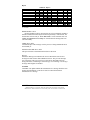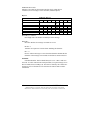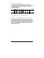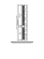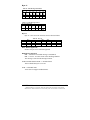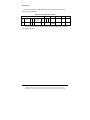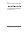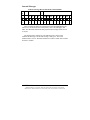
1
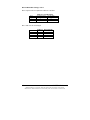
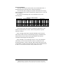
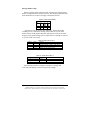
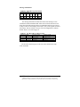
RS-232 to J1939 Converter CE Model 1939STB Documentation Number 1939STB4600 International Headquarters B&B Electronics Mfg. Co. Inc. 707 Dayton Road -- P.O. Box 1040 -- Ottawa, IL 61350 USA Phone (815) 433-5100 -- General Fax (815) 433-5105 Home Page: www.bb-elec.com Sales e-mail: [email protected] -- Fax (815) 433-5109 Technical Support e-mail: [email protected] -- Fax (815) 433-5104 European Headquarters B&B Electronics Ltd. Westlink Commercial Park, Oranmore, Co. Galway, Ireland Phone +353 91 792444 -- Fax +353 91 792445 Home Page: www.bb-europe.com Sales e-mail: [email protected] Technical Support e-mail: [email protected] B&B Electronics – November 2000 1939STB4600 Manual Cover Page B&B Electronics Mfg Co Inc – 707 Dayton Rd - PO Box 1040 - Ottawa IL 61350 - Ph 815-433-5100 - Fax 815-433-5104 B&B Electronics Ltd – Westlink Commercial Park – Oranmore, Galway, Ireland – Ph +353 91-792444 – Fax +353 91-792445 Table of Contents INTRODUCTION ...................................................................................... 1 SAE Publications.................................................................................. 1 WARNING!................................................................................ 2 DESCRIPTION ............................................................................................. 3 Physical Description ............................................................................ 4 Electrical Specification ........................................................................ 4 Communication directed to the device ................................................. 5 Control Byte 3 ............................................................................................. 6 Control Byte 4 ............................................................................................. 7 Internal Functions ................................................................................ 8 Vendor String .............................................................................................. 8 RS-232 Baud Change .................................................................................. 9 External Commands ........................................................................... 13 Message Header Setup............................................................................... 14 Message Information ................................................................................. 15 Byte 5 ........................................................................................................ 16 Byte 6 ........................................................................................................ 17 Byte 11 ...................................................................................................... 18 SAE-J1939 CONTROL HEADER.......................................................... 19 BYTE 7 .................................................................................................... 21 BYTE 8 .................................................................................................... 23 BYTES 9 AND 10...................................................................................... 25 BYTE 11 .................................................................................................. 26 Data Field .................................................................................................. 28 Reception of Data ...................................................................................... 29 SAE-J1939 BUS ...................................................................................... 29 INTERNAL MESSAGES ........................................................................ 31 SOFTWARE ............................................................................................. 32 Installation ................................................................................................. 32 Message Transmission............................................................................... 34 Message Reception .................................................................................... 34 Saving Message Information .................................................................... 35 File Logging ............................................................................................... 35 APPENDIX A: EXTENDED CAN/SAE-J1939 MESSAGE FRAME A-1 APPENDIX B: EXAMPLE.................................................................... B-1 1939STB4600 Manual Table of Contents B&B Electronics Mfg Co Inc – 707 Dayton Rd - PO Box 1040 - Ottawa IL 61350 - Ph 815-433-5100 - Fax 815-433-5104 B&B Electronics Ltd – Westlink Commercial Park – Oranmore, Galway, Ireland – Ph +353 91 792444 – Fax +353 91 792445 i Introduction SAE-J1939 is a communication protocol developed by SAE (Society of Automotive Engineers). The communication protocol is based on the CAN specification developed by Bosch 2.0 part B (September, 1991). Before using the Model 1939STB the user should be familiar with the SAE publications listed below, and follow all the guidelines before attempting to connect to an active J1939 network. The SAE-J1939 specifications are guidelines. Many manufacturers have proprietary data codes developed for their own use. The user must obtain these codes from the manufacturer of the vehicle. B&B Electronics does not have access to the SAE-J1939 codes, and cannot provide any assistance in obtaining these codes. It is the responsibility of the user to obtain and implement the specific J1939 codes for the vehicle(s) that the 1939STB is interfaced to. SAE Publications Surface Vehicle Recommended Practice SAE-J1939/11 Physical Layer – 250k bits/s, Shielded Twisted Pair (issued DEC94) SAE-J1939/21 Data Link Layer (issued JUL94) SAE-J1939/31 Recommended Practice for Serial Control and Communications Vehicle Network – Part 31- Network Layer (issued DEC94) SAE-J1939/71 Vehicle Application Layer (revised MAY96) SAE-J1939/73 Application Layer –Diagnostics (issued FEB96) SAE-J1939/81 Recommended Practice for Serial Control and Communications Vehicle Network – Park 81 – Network Management (issued JUL97) You may order these documents from SAE at (412) 776-4970 FAX: (412) 776-0790 Or on the web at http://www.sae.org CAN Specification 2.0 Robert Bosch GmbH Postfach 50 D-7000 Stuttgart 1, Germany 1939STB4600 Manual B&B Electronics Mfg Co Inc – 707 Dayton Rd - PO Box 1040 - Ottawa IL 61350 - Ph 815-433-5100 - Fax 815-433-5104 B&B Electronics Ltd – Westlink Commercial Park – Oranmore, Galway, Ireland – Ph +353 91 792444 – Fax +353 91 792445 1 WARNING! This Model 1939STB Converter Module allows you to connect to active SAE J-1939 networks. It is possible that your transmissions through this converter module could cause malfunction of the network operation, damage to the software or equipment, or bodily harm. Do Not Transmit Any Messages to The Network without a complete understanding of the operation of the network. B&B Electronics Mfg. Co. specifically disclaims any responsibility for damage or injury to software, hardware, equipment or persons as a result of using this product. WARNING! 2 1939STB4600 Manual B&B Electronics Mfg Co Inc – 707 Dayton Rd - PO Box 1040 - Ottawa IL 61350 - Ph 815-433-5100 - Fax 815-433-5104 B&B Electronics Ltd – Westlink Commercial Park – Oranmore, Galway, Ireland – Ph +353 91 792444 – Fax +353 91 792445 Description The 1939STB is an interface device allowing the user to connect a PC to an SAE-1939 bus via a serial port. The 1939STB conforms to the Physical Layer specification as set forth in SAE-J1939/11. The 1939STB allows the reception and transmission of messages over an SAE-J1939 standard bus. This converter has 14 message “slots” that can be configured for either reception or transmission. A sample program is provided to aid in the setup of the interface. Source code is provided and can be found in a subdirectory under B&B Electronics/J1939/VB6. The Visual Basic program runs under Windows: however, setup and data transfers can be sent and received by any terminal capable of serial communications. The power supply is a wide-range design and will accept a DC voltage between 10 and 42 volts. The 1939STB has reverse polarity protection. Power is connected to the 1939STB though a terminal block located under the snap cover. +DC is connected to the terminal marked “POWER”. -DC is connected to the terminal marked “GND”. The serial port on the 1939STB is a 9-pin male connection, configured as DCE (pin 2 receive// pin 3 transmit). The serial baud rate is user selectable between 300 and 57600. The stop, parity, and word length can also be adjusted. Two LED’s are provided on the 1939STB. One indicates that DC power is connected to the converter and the power supply is working properly. This LED will be lit constantly. The second LED is labeled “DATA”. This LED monitors the function of the converter. After the device is connected, the LED should flash approximately once every 2 seconds. The flashing LED confirms that the converter is operating properly and is ready to accept data. Connection to the SAE-J1939 bus is made by a terminal connection. The terminal, located under the snap cover, is marked “CAN LOW and “CAN HIGH”. In some applications it may be necessary to add a terminating resistor across the CAN high/low terminals. Consult the SAE-J1939/11 publication for details concerning terminating resistors. The terminals marked “ A” and “B” are not used. 1939STB4600 Manual B&B Electronics Mfg Co Inc – 707 Dayton Rd - PO Box 1040 - Ottawa IL 61350 - Ph 815-433-5100 - Fax 815-433-5104 B&B Electronics Ltd – Westlink Commercial Park – Oranmore, Galway, Ireland – Ph +353 91 792444 – Fax +353 91 792445 3 Physical Description Length: Width: Height: Serial Connection: SAE-J1939 Connection: Power Connection: Temperature: 5.25 in. (134mm) 2.75 in. (70mm) 1.00 in (25.4mm) DB-9 female, DCE Terminal block, CAN HIGH/CAN LOW Terminal block, POWER/GND 0 to +70 degrees Centigrade Electrical Specification Input Power Requirement: 10 to 42 volts DC, 1 Watt max. Meets Physical Layer SAE-J1939/11 Fully compatible with ISO 11898-24v standard RS-232 driver meets EIA-232-E and V.28 specification CAN transceiver meets ISO 11898-24 V standard 4 1939STB4600 Manual B&B Electronics Mfg Co Inc – 707 Dayton Rd - PO Box 1040 - Ottawa IL 61350 - Ph 815-433-5100 - Fax 815-433-5104 B&B Electronics Ltd – Westlink Commercial Park – Oranmore, Galway, Ireland – Ph +353 91 792444 – Fax +353 91 792445 Communication directed to the device Format: Message header B B B B 1 2 3 4 B 5 8 1 9 5 2 1 1 F 0 5 Table 1. J1939STB Format Message Information B B B B B B B B 6 7 8 9 1 1 1 1 0 1 2 3 E 0 8 0 4 8 4 4 7 c 0 0 0 c 1 2 B 1 4 4 3 Data Payload B B B 1 1 1 5 6 8 4 4 4 4 5 6 B 1 9 4 7 B 2 0 4 8 All communications to the device start with a message header (white area). This header is removed from any message sent to the J1939 bus. The header is four bytes long. Two bytes (B1& B2) are used to confirm start of frame. The next two bytes (B3 & B4) contain information controlling how the 1939STB functions. The remainder of the packet is the data payload and can contain from zero to sixteen bytes depending on function. Table 2. Transmit Data Format Byte 1 Check 1 Byte 2 Check 2 Byte 3 Control 1 Byte 4 Control 2 Message Information Data Payload The first two bytes (Check 1 and Check 2) are always set to 81hex and 21hex. These bytes must precede all data sent to the device. If the Check bytes are not sent consecutively the message will be rejected. The entire message must be resent before data can be transmitted to the device. Control (byte 3 and byte 4) contain information that is used by the converter. This information is not passed to the J1939 bus. Both control bytes must contain data (cannot have a value of 00) or the transmission will be rejected. 1939STB4600 Manual B&B Electronics Mfg Co Inc – 707 Dayton Rd - PO Box 1040 - Ottawa IL 61350 - Ph 815-433-5100 - Fax 815-433-5104 B&B Electronics Ltd – Westlink Commercial Park – Oranmore, Galway, Ireland – Ph +353 91 792444 – Fax +353 91 792445 5 Control Byte 3 Byte 3 directs the data packet to the proper destination. The setting of this byte will affect the rest of the message. That is to say changing this byte changes the meaning of the following data bytes. Bit 7 Table 3. Bits of Byte 3 Nibble 1 Bit 4 Bit 3 Bit 2 Bit 1 Nibble 2 Bit 6 Bit 5 Bit 0 Byte 3 has two parts, Nibble 1 and Nibble 2. Nibble 2 (bits 4 – 7) sets the control code as follows: Bit Number Bit 7 Table 4. Byte 3 Nibble 2 Function Value 1 0 1 0 1 0 1 0 Bit 6 Bit 5 Bit 4 Reserved not used Reserved not used Reserved not used Reserved not used Internal commands (Baud rate, Version number) No function External commands (Messages to J1939 bus) No function Nibble 1 (bits 0 – 3) of control byte 3 defines the number of bytes in the data payload of the message. The byte count does NOT include the message header (bytes 1 through 4). The message payload is limited to 16 bytes. This limit allows a complete J1939 packet to be sent or received from the bus. Byte 1 Check 1 Byte 2 Check 2 Table 5. Transmit Data Format Byte 4 Message Information Data Payload Control 2 << Count Number of Bytes for byte 3 nibble 1 >> Byte 3 Control 1 Nibble 1 of control byte 3 can be set to any value between 0 and 16 (0 to F hex). Bit Number Bit 3 Bit 2 Bit 1 Bit 0 6 Value 1 0 1 0 1 0 1 0 Table 6. Byte 3 Nibble 1 Function Number of bytes in data payload (MSB) Number of bytes in data payload Number of bytes in data payload Number of bytes in data payload (LSB) 1939STB4600 Manual B&B Electronics Mfg Co Inc – 707 Dayton Rd - PO Box 1040 - Ottawa IL 61350 - Ph 815-433-5100 - Fax 815-433-5104 B&B Electronics Ltd – Westlink Commercial Park – Oranmore, Galway, Ireland – Ph +353 91 792444 – Fax +353 91 792445 Control Byte 4 When control byte 3 is set to “external commands” (bit 4 set to 1), nibble 1 of control byte 4 is used to tell the J1939 in which message slot location (1 through 15) to place the message data. NOTE: Message location number 15 is receive only. Table 7. Byte 4 Bit 7 Nibble 2 Bit 6 Bit 5 Bit 4 Bit 3 Nibble 1 Bit 2 Bit 1 Bit 0 When control byte 3 is set to “ internal commands” (bit 5 set to 1), nibble 1 of control byte 4 has the following functions: Nibble 1 Value 0001 0010 0100 1000 Table 8. Nibble 1 Bit Values Function Display vender number & version Set baud rate, stop, start bits Not used Not used Nibble 2 of control byte 4 is reserved for future use and is set to 0. 1939STB4600 Manual B&B Electronics Mfg Co Inc – 707 Dayton Rd - PO Box 1040 - Ottawa IL 61350 - Ph 815-433-5100 - Fax 815-433-5104 B&B Electronics Ltd – Westlink Commercial Park – Oranmore, Galway, Ireland – Ph +353 91 792444 – Fax +353 91 792445 7 Internal Functions While most of the information sent and received from the 1939STB will be transferred to the J1939 bus, the internal function codes allow the user to set up the serial port, and receive an identity string from the 1939STB. The identity string may be used to verify that the 1939STB is connected and working properly. Vendor String The vendor string function is sent to the 1939STB as shown in the table below. This function is strictly internal and can be sent to the 1939STB at any time whether or not the 1939STB is connected to an active J1939 bus. The shaded areas are to be set by the user. Table 9. Vendor String Setup Byte 1 81 81 Byte 2 21 21 Byte 3 Nibble 2 Nibble 1 0010 0000 20hex Byte 4 Nibble 2 Nibble 1 0000 0001 01hex After this is sent to the 1939STB the device will respond with: I D 4 2 Table 10. Message Received from the SAE-J1939 Bus J1939 MC Data Address 0 0 0 0 00 A xx xx xx xx xx xx 0 0 0 0 A Function 28 xx See “Reception of Data” for an explanation of codes. The xx may change. The included Visual Basic application has a script file, VENDN.CVS, that can be sent to the 1939STB to illustrate the vendor string function. 8 1939STB4600 Manual B&B Electronics Mfg Co Inc – 707 Dayton Rd - PO Box 1040 - Ottawa IL 61350 - Ph 815-433-5100 - Fax 815-433-5104 B&B Electronics Ltd – Westlink Commercial Park – Oranmore, Galway, Ireland – Ph +353 91 792444 – Fax +353 91 792445 A A RS-232 Baud Change Setting byte-3/nibble-2 to 2 and byte-4/nibble-1 to 2 causes the 1939STB to change baud. This function also requires 3 bytes of additional information bytes 5, 6, and 7. It is important to note that after a baud change the PC must have its baud changed to match the baud of the 1939STB for communication to exist. If communication is lost after a baud change and cannot be recovered, disconnecting the 1939STB from its power source will restore the 1939STB to its default baud rate of 9600 baud, 1 stop bit, 8 data bits, no parity. Table 11. Baud Rate Setup Byte 1 81 81 Byte 2 21 21 Byte 3 Nibble 2 Nibble 1 0010 0011 23 hex Byte 4 Nibble 2 Nibble 1 0000 0010 02 hex Byte 5 UB3 Byte 6 Baud 1 Byte 7 Baud 2 03 hex 00 hex 06 hex Table 11 shows how an internal command is used to set the 1939STB to a baud rate of 300, 1 stop bit, 8 data words, and no parity. Byte 3 nibble 2 sets the internal command function. A nibble value of 2 sets the J1939STB into the Internal Function mode. Nibble 1 of byte 3 tells the 1939STB 3 bytes will follow Byte 4. Byte 4, nibble 1 is set to 2 telling the 1939STB to perform a baud change using the information contained in bytes 5, 6, and 7. Table 12. Baud Rate Setup Baud Rate Decimal Divisor 300 1556 1200 384 2400 192 9600 48 19200 24 38,400 12 57,600 8 * Setup default value. Hex Divisor MSB (Baud 2) 06 hex 01 hex 00 hex 00 hex * 00 hex 00 hex 00 hex Hex Divisor LSB (Baud 1) 00 hex 80 hex C0 hex 30 hex * 18 hex 0C hex 08 hex 1939STB4600 Manual B&B Electronics Mfg Co Inc – 707 Dayton Rd - PO Box 1040 - Ottawa IL 61350 - Ph 815-433-5100 - Fax 815-433-5104 B&B Electronics Ltd – Westlink Commercial Park – Oranmore, Galway, Ireland – Ph +353 91 792444 – Fax +353 91 792445 9 RS-232 Baud Rate Change - cont’d. All baud rates are entered as hex numbers. To determine the decimal divisor use the following formula. The decimal number must be converted to hexadecimal before entering the number into byte 6 and 7. Baud rates faster than 57,600 are not supported. UART clock = 7,372,800 Hz Decimal Divisor = Clock frequency (7,372,800) Baud output x 16 If you want a baud rate output of 300 baud: Decimal Divisor = 7,372,800 300 x 16 Decimal Divisor = 1536 = 600 hex Baud 1= 00 Baud 2= 06 Programming a baud rate change to 300 baud, 1 stop bit, 8 bit data, no parity. Table 13. Baud Rate Setup Byte 1 81 81 Byte 2 21 21 Byte 3 Nibble 2 Nibble 1 0010 0011 23 hex Byte 4 Nibble 2 Nibble 1 0000 0010 02 hex Byte 5 UB3 Byte 6 Baud 1 Byte 7 Baud 2 03 hex 00 hex 06 hex Table 13 is set to produce a baud rate of 300, 1stop bit, an 8 bit data word, and no parity. 10 1939STB4600 Manual B&B Electronics Mfg Co Inc – 707 Dayton Rd - PO Box 1040 - Ottawa IL 61350 - Ph 815-433-5100 - Fax 815-433-5104 B&B Electronics Ltd – Westlink Commercial Park – Oranmore, Galway, Ireland – Ph +353 91 792444 – Fax +353 91 792445 RS-232 Baud Rate Change cont’d. Baud Change; Parity, word length, stop bits. Byte 5 (UB3) UB3 sets the LCR register on the UART Table 14. Byte 5 (UB3) Bit 7 Divisor latch Bit 6 Set break Bit 5 Set parity Bit 4 Even parity Bit 3 Parity enable Bit 2 Stop bits Bit 1 Word length 1 Bit 0 Word length 0 Bit 7 = 1 allows baud rate divisor to be changed. 0 baud rate change is blocked. Bit seven should not be set. The setting and resetting of this bit is handled internally. Bit 6 = 1 forces the transmitter output to a logic 0 for alerting the remote receiver to a line break. 0 No break condition. Bits 5, 4, 3 work together to set parity. Table 15. Parity Setup Bit 5 X 0 0 1 1 1939STB4600 Manual Bit 4 Bit 3 X 0 0 1 1 1 0 1 1 1 * Setup Default Value. Parity Selection No parity * Odd parity Even parity Force parity “1” Force parity “0” 11 B&B Electronics Mfg Co Inc – 707 Dayton Rd - PO Box 1040 - Ottawa IL 61350 - Ph 815-433-5100 - Fax 815-433-5104 B&B Electronics Ltd – Westlink Commercial Park – Oranmore, Galway, Ireland – Ph +353 91 792444 – Fax +353 91 792445 RS-232 Baud Rate Change cont’d. Bit 2 stop bit works in conjunction with bits 1 and bit 0. Table 16. Stop Bit Setup Bit 2 0 1 1 Word length (bits) 5, 6, 7, 8 5 6, 7, 8 * Setup default value. Stop bit length 1* 1½ 2 Bits 1 and 0 set the word length. Table 17. Word Length Bit 1 0 0 1 1 12 Bit 2 Word length 0 5 1 6 0 7 1 8* * Setup default value. 1939STB4600 Manual B&B Electronics Mfg Co Inc – 707 Dayton Rd - PO Box 1040 - Ottawa IL 61350 - Ph 815-433-5100 - Fax 815-433-5104 B&B Electronics Ltd – Westlink Commercial Park – Oranmore, Galway, Ireland – Ph +353 91 792444 – Fax +353 91 792445 External Commands The SAE-J1939 format is based on the CAN extended data frame. A detailed breakdown of the data frame is shown in Appendix A. The arbitration field is changed to conform to the SAE-J1939 message frame. The message frame must be broken down further before it can be sent to the 1939STB. The format for transmitting data to the 1939STB is shown in the following table: Table 18. J1939 Format Message Header B B B B 1 2 3 4 Message Information B B B B B 5 6 7 8 9 8 1 9 5 2 1 1 F 0 5 E 7 0 c 8 0 0 0 B 1 0 4 0 B 1 1 8 c B 1 2 4 1 B 1 3 4 2 B 1 4 4 3 Data Payload B B B 1 1 1 5 6 8 4 4 4 4 5 6 B 1 9 4 7 The message sent to the converter is formatted as shown above. The format is divided into three sections. Each section performs a specific function as follows: Bytes 1 through 4 (B1-B4) are internal commands for the converter. These bytes tell the converter if the following message is intended for the SAE-J1939 bus, the slot where the message should be stored on the 1939STB, and the length of the data payload. Bytes 5 through 11 are for message control - if it is to be transmitted (data frame) or received (remote frame). This area contains the J1939 message information: priority, data page, PDU format, PDU specific, and source address. The last section is the data section. This is the data that will be sent to, or received from, the bus. It may contain 0 to 8 bytes. 1939STB4600 Manual 13 B&B Electronics Mfg Co Inc – 707 Dayton Rd - PO Box 1040 - Ottawa IL 61350 - Ph 815-433-5100 - Fax 815-433-5104 B&B Electronics Ltd – Westlink Commercial Park – Oranmore, Galway, Ireland – Ph +353 91 792444 – Fax +353 91 792445 B 2 0 4 8 Message Header Setup Before a message can be sent to the SAE-J1939 bus, the message header must be configured to direct the data correctly. The following table shows the bytes that must be set to direct a message to the SAE-J1939 bus. Table 19. J1939 Message Header Message Header B B B B 1 2 3 4 81 21 1F 05 The first two bytes are for the start of message. The third byte (B3) containing hex 1F,1 directs the message to the J1939 bus. (F) hex is the number of bytes in the payload. Byte four (B4) tells the converter in which message slot to put the message (slot 5). Valid slots are 1 through 15, but slot 15 is reserved for receive only. Nibble 2 Value 1 2 Table 20. Valid Codes for Byte 3 Function Message directed to SAE-J1939 bus Internal commands, vender #, baud change Nibble 1 0 to 15 Number of bytes to follow byte 4 Table 21. Valid Codes for Byte 4 Function Nibble 2 Nibble 1 No function (reserved) Value = 0 Message slot number Value = 1 to 15 (1 to F hex) Each message must have a unique slot number. A message sent to the same slot number overwrites the previous message. 14 1939STB4600 Manual B&B Electronics Mfg Co Inc – 707 Dayton Rd - PO Box 1040 - Ottawa IL 61350 - Ph 815-433-5100 - Fax 815-433-5104 B&B Electronics Ltd – Westlink Commercial Park – Oranmore, Galway, Ireland – Ph +353 91 792444 – Fax +353 91 792445 Message Information Table 22. J1939 Message Information Message Information B B B B 5 6 7 8 95 E7 0C 80 B 9 00 B 10 40 B 11 8C The message information controls the action of the message. It also contains the header information that will be sent out on the J1939 bus. The bytes that control the message and are not transmitted to the bus are grayed in. Byte 5 and 6 are the message control bytes. They work together to control the message. The bit fields are set up in a two bit configuration as follows: NOTE: Byte 11 covered on page 18. Table 23. Two Bit Values for Byte 5 and 6 Value of 2 bit field 0 0 0 1 1 0 1 1 Function on write Reserved Reset element Set element No change Function on read Reserved Element is reset Element is set Reserved The bit values shown in gray are the only values valid for the setup of the 1939STB. 1939STB4600 Manual 15 B&B Electronics Mfg Co Inc – 707 Dayton Rd - PO Box 1040 - Ottawa IL 61350 - Ph 815-433-5100 - Fax 815-433-5104 B&B Electronics Ltd – Westlink Commercial Park – Oranmore, Galway, Ireland – Ph +353 91 792444 – Fax +353 91 792445 Byte 5 Table 24. Byte 5 Bit Function Sets the message valid Sets the message invalid Transmit interrupt set Transmit interrupt not set Receive interrupt set Receive not set Interrupt has occurred No interrupt pending Bit 7 Bit 6 MSGVAL 1 0 0 1 Bit 5 1 0 Byte 5 Bit 4 Bit 3 Bit 2 TXIE RXIE Bit 1 Bit 0 INTPND 0 1 1 0 0 1 1 0 NOTE: The dark gray (white letters) should be set to this value when sending a new message to the 1939STB. MSGVAL Bits 6 and 7 Message Valid. The message must be valid before any operations can be preformed on it. Messages can be preloaded on the converter and activated / deactivated as needed. Note that all messages locations are set invalid at power up. Any time the converter is reset, all message information is lost. TXIE Bits 5 and 4 Transmit Interrupt Enable. Set bit(s) INTPND after a message is successfully sent to the bus. RXIE Bits 3 and 2 Receive Interrupt Enable. Set bit(s) INTPND after a message is received from the bus. NOTE: It is possible to send a remote frame by setting both the TXIE and RXIE. The controller will clear the TXIE after the message is sent or if the data is received before the message can be sent. INTPND Bits 1 and 0 Interrupt Pending. Indicates that a message object has generated an interrupt request. Be aware that when a message is being serviced by the controller, it is temporarily inactive. This prevents a message from being overwritten by the J1939 controller while the message is being loaded to the serial port. During the upload the message location cannot receive or transmit. 16 1939STB4600 Manual B&B Electronics Mfg Co Inc – 707 Dayton Rd - PO Box 1040 - Ottawa IL 61350 - Ph 815-433-5100 - Fax 815-433-5104 B&B Electronics Ltd – Westlink Commercial Park – Oranmore, Galway, Ireland – Ph +353 91 792444 – Fax +353 91 792445 0 1 Byte 6 Table 25. Byte 6 Bit Function Remote Pending Bit 7 Bit 6 RMTPND 1 0 0 1 Transmit Request Message lost/ CPU update Byte 6 Bit 5 Bit 4 Bit 3 Bit 2 TXRQ MSGLIST/CPUUPD 1 0 Bit 1 Bit 0 NEWDAT 0 1 1 0 0 1 New data in message slot 1 0 NOTE: the dark gray (white letters) should be set to this value when sending a new message to the 1939STB. RMTPND Bits 7 and 6 Remote Pending (used for messages that are to be transmitted). Indicates that the transmission of this object has been requested by a remote node, but the data has not been sent yet. When RMTPND is set the controller also sets TXRQ. Both RMTPND and TXRQ are cleared when the message has been sent successfully. TXRQ Bits 5 and 4 Transmit Request. This message is in the process of being transmitted and is not finished yet. MSGLST/CPUUPD Bits 3 and 2 This pair of bits has a dual function based on its direction. Receive MSGLST. Message Lost indicates the J1939 controller has stored a new message into this location while NEWDAT was set. The previous message was overwritten. This can occur for several reasons. The MPU was busy doing other tasks, transmitting a serial message, error checking or servicing a message with a higher slot number. Transmit CPUUPD. CPU update inhibits the transmission of a message while the CPU updates the information. It can also be used to control the automatic transmission of a message. 1939STB4600 Manual 17 B&B Electronics Mfg Co Inc – 707 Dayton Rd - PO Box 1040 - Ottawa IL 61350 - Ph 815-433-5100 - Fax 815-433-5104 B&B Electronics Ltd – Westlink Commercial Park – Oranmore, Galway, Ireland – Ph +353 91 792444 – Fax +353 91 792445 0 1 NEWDAT Bits 1and 0 Indicates if new data has been written into this slot by either the bus controller (receive messages) or the controller (transmit objects). Byte 11 Table 26. Byte 11 Bit Function Bit 7 Byte 11 Bit 6 Bit 5 Bit 4 Bit 3 Bit 2 DIR XT D DLC Number of data bytes (0 to 8) Message direction: Transmit Message direction: Receive Extended identifier must be 1 Bit not used set to 0 Bit not used set to 0 Bit 1 1 0 1 X X DLC Bits 7, 6, 5 and 4 Data length code. The number of data bytes in the message. DIR Bit 3 Direction. Defines if a message is transmit or receive. Bit Set = 1 Transmit on reception of a remote frame matching the identifier. Bit = 0 Receive. When a message is received with an identifier that matches the identifier of the message stored in this slot the data is stored in this slot. XTD Bit2 Extended identifier. This bit should always be set to 1. Bits 1 and 0 are not used. To send a remote frame to Request Data, set up the message slot to Receive Mode, then set TXRQ (10). This will be cleared by the control once the data is sent or if the data is received before the remote frame could be transmitted. 18 Bit 0 1939STB4600 Manual B&B Electronics Mfg Co Inc – 707 Dayton Rd - PO Box 1040 - Ottawa IL 61350 - Ph 815-433-5100 - Fax 815-433-5104 B&B Electronics Ltd – Westlink Commercial Park – Oranmore, Galway, Ireland – Ph +353 91 792444 – Fax +353 91 792445 SAE-J1939 Control Header Bytes 7 though 10 are the bytes that set the header information (“Arbitration Field” in the following table) for the SAE-J1939 bus. The areas shown in Table 27 in dark gray are set by the CAN specification and are NOT modified by SAE-J1939. Table 27. J1939 Message Frame S O F 1 ARBITRATION FIELD S I Identifier Identifier R D Extension (11 Bits) S E (18 Bits) 11 Bits 1 1 18 Bits R T R 1 CONTROL R R D 1 0 L C 6 Bits DATA CRC ACK EOF 64 Bits 16 Bits 2 Bits 7 Bits The frame above shows the entire J1939/CAN frame. Table 28 on the following page shows the Arbitration field in detail. Dark gray areas are part of the CAN standard and are set by the controller. The double black lines separate the CAN message identifiers (upper part) from the SAE-J1939 message identifiers (lower part). The area between the black lines highlighted in dark gray/white letters shows the bytes that must be entered to set up the SAE-J1939 message header. In the back of the manual you will find a worksheet, (Appendix A) and an example (Appendix B) to help set up the message header. 1939STB4600 Manual 19 B&B Electronics Mfg Co Inc – 707 Dayton Rd - PO Box 1040 - Ottawa IL 61350 - Ph 815-433-5100 - Fax 815-433-5104 B&B Electronics Ltd – Westlink Commercial Park – Oranmore, Galway, Ireland – Ph +353 91 792444 – Fax +353 91 792445 20 1939STB4600 Manual B&B Electronics Mfg Co Inc – 707 Dayton Rd - PO Box 1040 - Ottawa IL 61350 - Ph 815-433-5100 - Fax 815-433-5104 B&B Electronics Ltd – Westlink Commercial Park – Oranmore, Galway, Ireland – Ph +353 91 792444 – Fax +353 91 792445 Byte 7 (Shown in Table 29) Bits 7, 6, and 5 of byte 7 set the J1939 priority bits. Bit 7 is the MSB. Bit 5 is the LSB. To code a priority value = 6 set bit 7 = 1 bit 6 = 1 bit 5 = 0. Bit 4 is the reserved bit - the J1939 specification sets this bit to zero. It may be used in the future therefore it is NOT hard coded. The user must set this bit to zero for every transmitted J1939 message. Bit 3 is the data page bit and select page 0 or page 1and is set by the user. Bits 2, 1, 0, are the MSB’s of the PDU format. 1939STB4600 Manual 21 B&B Electronics Mfg Co Inc – 707 Dayton Rd - PO Box 1040 - Ottawa IL 61350 - Ph 815-433-5100 - Fax 815-433-5104 B&B Electronics Ltd – Westlink Commercial Park – Oranmore, Galway, Ireland – Ph +353 91 792444 – Fax +353 91 792445 22 1939STB4600 Manual B&B Electronics Mfg Co Inc – 707 Dayton Rd - PO Box 1040 - Ottawa IL 61350 - Ph 815-433-5100 - Fax 815-433-5104 B&B Electronics Ltd – Westlink Commercial Park – Oranmore, Galway, Ireland – Ph +353 91 792444 – Fax +353 91 792445 Byte 8 (Shown in Table 30) Bits 7, 6, 5, 4, and 3 of Byte 8 along with Bits 2, 1, and 0 of Byte 7 make up the first part of the PDU (Protocol Data Unit). The first 8 bits are the PDU format. The values for specific formats will have to be supplied by the user. Bits 2, 1, and 0 of Byte 8 and bits 7, 6, 5, 4, and 3 of Byte 9 make up the second part of the PDU. The eight bits are the PDU specific. Values for the PDU specific will have to be supplied by the user . NOTE: It is a common practice to combine the first and second parts of the PDU into a single number. When given the PDU as a single number, bit 2 of byte 7 is the MSB and bit 3 of byte 9 is the LSB. 1939STB4600 Manual 23 B&B Electronics Mfg Co Inc – 707 Dayton Rd - PO Box 1040 - Ottawa IL 61350 - Ph 815-433-5100 - Fax 815-433-5104 B&B Electronics Ltd – Westlink Commercial Park – Oranmore, Galway, Ireland – Ph +353 91 792444 – Fax +353 91 792445 24 1939STB4600 Manual B&B Electronics Mfg Co Inc – 707 Dayton Rd - PO Box 1040 - Ottawa IL 61350 - Ph 815-433-5100 - Fax 815-433-5104 B&B Electronics Ltd – Westlink Commercial Park – Oranmore, Galway, Ireland – Ph +353 91 792444 – Fax +353 91 792445 Bytes 9 and 10 (Shown in Table 31) Bits 7, 6, 5, 4 and 3 complete the PDU. Bits 2, 1, and 0 of byte 9 and bits 7, 6, 5,and 4 of byte 10 are the Source Address for the converter. Each Source Address MUST be unique. SAE J1939-81 describes address management and allocation in detail and should be consulted before connecting to a J1939 bus. Addresses 249 and 250 are designated for offboard diagnostic service tools. WARNING: These addresses are SUGGESTED. The procedure described in SAE J1939-81 should be followed when connecting to any unknown bus. 1939STB4600 Manual 25 B&B Electronics Mfg Co Inc – 707 Dayton Rd - PO Box 1040 - Ottawa IL 61350 - Ph 815-433-5100 - Fax 815-433-5104 B&B Electronics Ltd – Westlink Commercial Park – Oranmore, Galway, Ireland – Ph +353 91 792444 – Fax +353 91 792445 26 1939STB4600 Manual B&B Electronics Mfg Co Inc – 707 Dayton Rd - PO Box 1040 - Ottawa IL 61350 - Ph 815-433-5100 - Fax 815-433-5104 B&B Electronics Ltd – Westlink Commercial Park – Oranmore, Galway, Ireland – Ph +353 91 792444 – Fax +353 91 792445 Byte 11 Table 32. J1939 Message Information Message Information B B B B B B B 5 6 7 8 9 10 11 95 E7 0C 80 00 40 8C Table 33. J1939 Message Control Message Information B B B B B B 5 6 7 8 9 10 95 E7 0C 80 00 40 B 11 8C Byte 11 Byte 11 is not sent to the J1939 bus and is coded as follows: Bit 7 DLC Bit 6 Table 34. Byte 11 DIR Bit 5 Bit 4 Bit 3 XTD Bit 2 Bit 1 Bit 0 DLC Data Length Code Number of bytes 0 to 8 in the data payload. DIR Message Direction DIR = 1 transmit. The loaded message is transmitted. DIR = 0 receive. A remote frame with a matching identifier. The message is stored in this message location. XTD Extended Identifier XTD = 1 Extended frame This bit should always be set to one. XTD = 0 Standard frame J1939 does not support standard frames. 1939STB4600 Manual 27 B&B Electronics Mfg Co Inc – 707 Dayton Rd - PO Box 1040 - Ottawa IL 61350 - Ph 815-433-5100 - Fax 815-433-5104 B&B Electronics Ltd – Westlink Commercial Park – Oranmore, Galway, Ireland – Ph +353 91 792444 – Fax +353 91 792445 Data Field The next 8 bytes are the data field and can have from 0 to 8 bytes used. This is the data payload. Table 35. J1939 Message Frame Arbitration Field S O F 1 Identifier (11 bits) 11 bits S R S 1 I D E 1 Identifier Extension (18 bits) 18 bits Control R T R 1 R 1 R 0 6 bits Data CRC ACK EOF 64 bits 16 bits 2 bits 7 bits D L C The remaining fields are handled by the controller and are not accessible through the converter. 28 1939STB4600 Manual B&B Electronics Mfg Co Inc – 707 Dayton Rd - PO Box 1040 - Ottawa IL 61350 - Ph 815-433-5100 - Fax 815-433-5104 B&B Electronics Ltd – Westlink Commercial Park – Oranmore, Galway, Ireland – Ph +353 91 792444 – Fax +353 91 792445 Reception of Data The 1939STB sends data to the RS-232 port and onto the PC using a 16 byte format. The first byte of the message is 42hex. The next byte is the Function byte. The next field displays the SAE-J1939 header. If an internal message is received then this field is filled with zero. The receive message header is detailed below. I D 4 2 Func 4 2 28 09 Table 36. Message Received from the SAE-J1939 Bus J1939 Address M Data C C 80 00 40 1 41 42 43 44 45 46 E 0 0 00 00 00 0 0 47 48 A A A A Table 36 shows the receive message. The black line separates the two types of messages that the 1939STB produces. Each message is detailed separately below. SAE-J1939 Bus Referring to Table 36 this is a message received from the SAE-J1939 bus. The first byte (ID) is the start of frame byte and is fixed at 42hex. The next byte is a function code byte. This byte is broken into two nibbles and decoded as follows: Bit 7 Table 37. Function Nibble 2 Bit 6 Bit 5 Bit 4 Bit 3 Nibble 1 Bit 2 Bit 1 Bit 0 The gray area shown in Table 36 is information that was not received from the bus, but is needed to track the message. ID Byte This is a start of a message and will always be 42Hex. 1939STB4600 Manual F F 29 B&B Electronics Mfg Co Inc – 707 Dayton Rd - PO Box 1040 - Ottawa IL 61350 - Ph 815-433-5100 - Fax 815-433-5104 B&B Electronics Ltd – Westlink Commercial Park – Oranmore, Galway, Ireland – Ph +353 91 792444 – Fax +353 91 792445 Function This is used to show where the message came from. Refer to Table 37. If the Nibble 2 is set to 0, then the message is from the J1939 bus. If Nibble 2 is set to 2, it is an internal message (for example, Vendor ID). Bit 7 Table 38. MC Nibble 2 Bit 6 Bit 5 Bit 4 Bit 3 Nibble 1 Bit 2 Bit 1 Bit 0 MC This is a byte from the controller. Nibble 2 is the number of data bytes (08) in the message. Nibble 1, Bit 3 is the message direction. Bit 2 should always be set to 1. Bit 1 and 0 are not used. 30 1939STB4600 Manual B&B Electronics Mfg Co Inc – 707 Dayton Rd - PO Box 1040 - Ottawa IL 61350 - Ph 815-433-5100 - Fax 815-433-5104 B&B Electronics Ltd – Westlink Commercial Park – Oranmore, Galway, Ireland – Ph +353 91 792444 – Fax +353 91 792445 Internal Messages I D 4 2 Func 4 2 28 09 Table 39. Message Received from the SAE-J1939 Bus J1939 Address M Data C C 80 00 40 1 41 42 43 44 45 46 47 E 0 0 00 00 00 00 48 A A A A Table 39 shows the data received from the J1939 bus highlighted in gray. The bytes (C,80,00,40) are the J1939 priority, reserve bit, data page, and PDU. The data field contains the data payload of the message and be from 0 to 8 bytes. The message starts with 42 hex. The function code is 28 hex. This identifies the message as an internal message 2 and type 8. The J1938 Address field is set to 0. The Data field has an AA hex at either end. The data between is variable. 1939STB4600 Manual F F 31 B&B Electronics Mfg Co Inc – 707 Dayton Rd - PO Box 1040 - Ottawa IL 61350 - Ph 815-433-5100 - Fax 815-433-5104 B&B Electronics Ltd – Westlink Commercial Park – Oranmore, Galway, Ireland – Ph +353 91 792444 – Fax +353 91 792445 Software The program included with the 1939STB is a Visual Basic program that allows the transmission and reception of simple messages from the SAEJ1939 bus. The source code for the program is included on the disk to aid in program development. Installation Two disks are provided with the 1939STB. Disk one is installed first. Start Windows and insert the disk in A: drive. Click on the Start icon. Then click on the Run icon. In the box type “a:setup”. Follow the screen instructions. If you follow all the default settings the program will be under Start/ Programs/ B&B Electronics / J1939stb. After installing the program use the icon to start the program. The first screen sets the PC’s com port. Choose the serial port where the 1939STB is connected. The default baud setting should be used. Click on enter to get to the next screen. 32 1939STB4600 Manual B&B Electronics Mfg Co Inc – 707 Dayton Rd - PO Box 1040 - Ottawa IL 61350 - Ph 815-433-5100 - Fax 815-433-5104 B&B Electronics Ltd – Westlink Commercial Park – Oranmore, Galway, Ireland – Ph +353 91 792444 – Fax +353 91 792445 This screen is divided into two parts. The upper half of the screen allows the user to fill out the individual bytes that configure the 1939STB. The lower part of the screen displays data received from the 1939STB. 1939STB4600 Manual 33 B&B Electronics Mfg Co Inc – 707 Dayton Rd - PO Box 1040 - Ottawa IL 61350 - Ph 815-433-5100 - Fax 815-433-5104 B&B Electronics Ltd – Westlink Commercial Park – Oranmore, Galway, Ireland – Ph +353 91 792444 – Fax +353 91 792445 Message Transmission (sending data to the 1939STB) The transmission window is divided into three rows. The first row is the internal header information. The second row contains message control information. The third row is the data payload sent with the information. The first row has 4 bytes. Bytes 1 and 2 are set to 8 and 21 hex. All data is entered in hex. The next two bytes, 3 and 4, are set by the user. Refer to pages 6 and 7 of this manual for help setting theses two bytes. Setting a byte is done by clicking in the box under the label and entering the proper hex value. All values in this row must contain information or the message will be rejected. The second row contains bytes 5 though 11. These bytes are set by the user. All values are entered in hex. All of the bytes in this row do NOT have to contain data for the message to be accepted. The last row is the data payload that is transmitted with an SAEJ1939 message. This row may contain data or left blank. Message Reception To receive information from the SAE-J1939 bus, the user must program the 1939STB to receive a message. This is done by first sending a receive message to the 1939STB. Page 18 explains how to configure a message to receive data. After the proper byte codes are entered into the 1939STB, the device “listens” on the SAE-J1939 bus for a message that matches the identity code of the reception message. The message header information and data are displayed in the lower window. The incoming data will fill in the slots from top to bottom. Once the data moves off the page it is lost. If a permanent copy of the data is needed use “Data Logging”. NOTE: MicroSoft Visual Basic only allows a buffer of approximately 3K. You must manually clear the Receive Message buffer or you will get a buffer overflow error. 34 1939STB4600 Manual B&B Electronics Mfg Co Inc – 707 Dayton Rd - PO Box 1040 - Ottawa IL 61350 - Ph 815-433-5100 - Fax 815-433-5104 B&B Electronics Ltd – Westlink Commercial Park – Oranmore, Galway, Ireland – Ph +353 91 792444 – Fax +353 91 792445 Saving Message Information To save a configuration: “the byte data” Click on File at the top of the page. When the box opens click on Save. When the next box opens select a directory where the file should be stored and name the file. Click Save. The file is saved. To recall the information in a previously saved file use the File import command. Select the name of the file you wish to use. Click on Open. The data will be loaded into the Transmit window. File Logging File logging allows the user to save the data from the receive window. To start data logging, click on Logging at the top of the page. Use SelectFile to set up the file to hold the information. Data logging is started/stopped by clicking on Toggle located on the Logging tab. 1939STB4600 Manual 35 B&B Electronics Mfg Co Inc – 707 Dayton Rd - PO Box 1040 - Ottawa IL 61350 - Ph 815-433-5100 - Fax 815-433-5104 B&B Electronics Ltd – Westlink Commercial Park – Oranmore, Galway, Ireland – Ph +353 91 792444 – Fax +353 91 792445 Appendix A. The Extended CAN / SAE-J1939 Message Frame Arbitration Field S O F 1 1 2 3 Priority (3 bits) 2 3 4 Identifier (11) bits 4 5 6 7 8 R 1 5 9 1 0 D PDU Format (PF) P (8 bits) 6 7 8 9 1 1 0 1 1 1 S R S 1 2 1 3 I 1 2 D E PF Cont 1 1 1 4 5 6 Control Field Identifier Extension (18 Bits) 7 8 9 1 1 1 1 1 1 1 0 1 2 3 4 5 6 PDU Specific (PS) Source Address (8 Bits) (8 Bits) 1 1 1 2 2 2 2 2 2 2 2 2 2 3 7 8 9 0 1 2 3 4 5 6 7 8 9 0 3 4 5 6 1 7 1 8 R T R R 1 R 0 1 DLC 2 3 4 3 1 3 2 3 3 3 4 3 5 3 6 3 7 3 9 3 8 Data Field CRC Field 8 bytes 64 bits 2 bytes 16 bits Ack Field EOF The table above shows a comparison between the SAE-J1939 message frame and the extended CAN message frame. The bold line separates the upper and lower parts of the table. The upper half of the table shows the CAN data frame labels and the lower part of the table contains the SAE-J1939 data labels. The areas that are in gray are controlled by the CAN controller and cannot be altered. The CAN extended frame is made up of 6 fields: Arbitration, Control, Data, CRC, ACK, EOF. The arbitration field is subdivided into two fields of 11 and 18 bit identifiers. CAN uses these fields to determine both identification and priority. The SAE-J1939 specification future subdivides the arbitration field as follows: Priority 3 bits with a value of 0 to 7 - with 0 having the highest priority. R1 1 bit. This bit is reserved by the SAE for future use and should be set to 0. DP Data Page 1bit. Sets an auxiliary page of parameter groups. PDU-Format 8 bit. One of the fields that makes up the Parameter Group Number. PDU-Specific 8 bit. The second field the makes up the Parameter Group Number. Source Address 8 bit. The address of the sending/receiving node. The fields above are required to send a message on the SAE-J1939 bus. Additionally the 8 byte data field may or may not contain data. An expanded view of the Arbitration field is shown on the following page. 1939STB4600 Manual Appendix A B&B Electronics Mfg Co Inc – 707 Dayton Rd - PO Box 1040 - Ottawa IL 61350 - Ph 815-433-5100 - Fax 815-433-5104 B&B Electronics Ltd – Westlink Commercial Park – Oranmore, Galway, Ireland – Ph +353 91 792444 – Fax +353 91 792445 A-1 Arbitration Field S O F X X X X X X Priority 3 Bits 1 1 0 R 1 * 0 1 2 4 5 7 6 Byte 7 5 4 D P PDU Format (PF) 8 Bits 0 1 1 1 1 0 0 6 7 8 9 10 11 12 3 2 1 0 Byte 8 7 6 5 S R S X X X X X X I D E X X X X X X PF Cont. PDU Specific 8 Bits Source Address 8 Bits (See note below.) 0 0 0 0 0 0 0 1 1 0 13 14 15 16 17 18 19 20 21 22 0 7 6 5 Byte E 8 cont. 4 3 2 1 Byte 9 4 3 23 24 25 26 27 28 29 2 1 0 7 Byte 10 6 5 4 30 3 R T R X X X X X X * R1 is the reserved bit. ALL messages should set the SAE reserved bit to 0 on transmit. The frame above represents the J1939 frame and shows how the data is coded, to be entered into the frame. The bits marked with an X are set by the controller and are NOT settable by the user and can be ignored. The easiest way to fill this out is to start at SOF bit, fill in the priority bits (3), the R1 bit, the data page DP bit and so on. After all 30 bits are set, break apart the bits in bytes following the separation highlighted in gray. The bytes are converted to hex and can be entered into the communication program provided by B&B as follows: NOTE: The bytes in the rest of the message (bytes 3, 4, 5, 6, and 11) must be filled out for the message to operate properly. A-2 1939STB4600 Manual B&B Electronics Mfg Co Inc – 707 Dayton Rd - PO Box 1040 - Ottawa IL 61350 - Ph 815-433-5100 - Fax 815-433-5104 B&B Electronics Ltd – Westlink Commercial Park – Oranmore, Galway, Ireland – Ph +353 91 792444 – Fax +353 91 792445 Appendix A Appendix B. Example This example uses the SAE “Electronic Axle Controller #1” (EAC#1). The specifications are as follows: Transmission Repetition Rate: Data Length: Data Page: PDU Format: PDU Specific: Default Priority: Parameter Group Number: Source Address: S O F X X X X X X Priority 3 Bits 1 2 3 R 1 * 1 1 2 4 5 6 1 Byte 7 5 4 0 0 7 1 D P 500 ms 8 bytes 0 240 5 6 61,446 (00F006) hex 249 (off-board diagnostic / service tool #1). See note below. PDU Format (PF) 8 Bits 1 1 2 3 4 5 6 6 7 8 9 10 11 12 0 1 Byte 8 7 6 5 1 0 0 3 0 2 1 1 1 S R S X X X X X X I D E X X X X X X PF Cont. PDU Specific 8 Bits 7 8 1 2 3 4 5 6 7 8 1 2 Source Address 8 Bits (See note below.) 3 4 5 6 13 14 15 16 17 18 19 20 21 22 23 24 25 4 0 Byte 8 cont. 3 2 1 0 0 0 0 0 7 0 6 0 5 1 Byte 9 4 3 0 1 2 1 0 28 7 8 29 30 26 27 7 Byte 10 6 5 4 3 R T R X X X X X X * R1 is the reserved bit. ALL messages should set the SAE reserved bit to 0 on Transmit. Byte 7 7 1 6 1 Binary 5 4 3 0 0 0 Convert to Hex 2 1 1 1 0 1 C7 Convert to Decimal 199 The hex number is the value sent to the 1939STB. NOTE: See SAE J1939–81 for Source Address management. 1939STB4600 Manual Appendix B B&B Electronics Mfg Co Inc – 707 Dayton Rd - PO Box 1040 - Ottawa IL 61350 - Ph 815-433-5100 - Fax 815-433-5104 B&B Electronics Ltd – Westlink Commercial Park – Oranmore, Galway, Ireland – Ph +353 91 792444 – Fax +353 91 792445 B-1