1
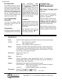
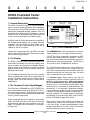
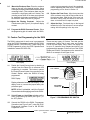
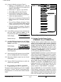
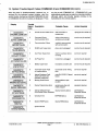
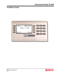
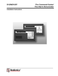
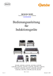
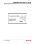
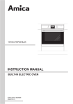
C-0636-020-01 0
A
R
I
D
0
N
I
C
S
D636A Command Center Specifications Sheet
Features
.
Displays complete system
status in English text
Used with the D4112 and
D6112 Control/
Communicators
l
.
Programmable custom text
for each zone
.
Easy to understand backlit
LCD Display
.
Illuminated touchpad
.
Red Armed Status LED
.
Programmable “idle display”
text
l
User friendly system status
sounder
.
Initiate local system test
and perimeter Watch from
the keypad
l
l
.
The D636A Command Center does
more than just arm and disarm the
D4112/D6112 security system.
When you use the Command Bar
with one or two other keys, the D636
gives you control over the entire
security system.
Three programmable onetouch function keys
.
.
Command Control
The D4112 and D6112 Control/
Communicators can be programmed for a wide variety of command
functions executed from the D636A
Command Center.
Multiple arming options and
special alarm options
Slim-line designer styling
compliments any decor.
Programmable Function
Keys
Three expansion zones
The D636A has three function keys,
and when used with the D6112, can
be programmed to perform most
system command functions (other
than arming commands) with the
touch of one key. When used with
Four-wire connection to the
control/communicator
7 5 - 0 5 5 0 6 - 0 0 0 - C 6/90
-
the D4112, the function keys are
preprogrammed. Function key “A”
is Command 44 (local system test),
function key “B” is Command 47
(reset detectors), and function key
“C” is Command 5 (passcode
change).
English Language Display
The D636A display consists of 2
lines, each containing 16 characters
of English-language text. The first
line is the idle text display. This line
can be programmed to display your
company name when the Command
Center is in the idle state.
The second line displays all system
events, giving the end user instant
identification of system status. No
guesswork is involved. Programmable displays for each protective
zone give your company’s installations that special customized touch.
Q 1989-1990 Radionics, Inc.
C-0636-020-020
Zone Expansion
The D636A provides the security
system with three additional end-ofline resistor supervised hardwire
protective zones (for use with the
D6112 only). The protective zones
report to the D6112 individually, and
can be controlled from any
Command Center assigned to the
same account as the zone.
User Programmable
Passcodes
Code
Programmer.
Basic
programming for the security system
is accomplished using the
6112:MAIN or D4 112:MAIN Product
Handler. Custom Text for the
D636A is programmed with the
D636 Keypad Handler. The D636
Keypad Handler allows you to
program one line of custom text for
each zone and one line of custom
text for the “idle display.”
Installation
The user can change existing
passcodes directly from the
Command Center.
Programming
All programming for the D636A is
accomplished with the D5100 Bar
Installing the D636A is simple, quick,
and cost effective. A four-conductor
cable is all that is required to connect
the D636A Command Center to the
control panel.
The expansion zones are fully
supervised using three 1 KC! end-ofline resistors (included).
Customize your
Installation with these
D636A Accessories-D54B Brass Faceplate: Comes
with a backbox for flushmount
applications.
D54C Stainless Steel Faceplate:
C o m e s w i t h a backbox for
flushmount applications.
D55 Desk Stand: Portable stand
made of attractive smoked
Plexiglass holds the D636A at a
comfortable angle for reading the
display and using the keys.
D56 Conduit Box: A surface mount
backbox for applications requiring
conduit protection for D636A wiring.
Specifications
Power:
Nominal 12 VDC supplied by the Control/Communicator auxiliary power supply
Current:
Idle:
27mA, keypad unlit, disarmed.
75mA, keypad lit, armed
Maximum: 104mA, keypad lit and warning tone “on”
Wiring :
A 22 gauge, 4-conductor cable supplies data-in, data-out, +12 VDC, and common.
A total maximum of 4 serial devices (D620, D630, D626, D636A or D640) may
be connected to the D6112 Control/Communicator. A total maximum of 2 serial
devices may be connected to the D4112.
Dimensions:
Height: 4.56”, Width: 8.15”,
Depth: 0.816”
Color:
Warm gray
Display:
Two-line 16-character Liquid Crystal Display (LCD). 15 characters of
programmable custom text. Backlit during entry delay, alarms, and when a
Command Center digit is depressed.
Keypad:
Backlighting of the keypad can be selected with a jumper:
Normal operation: Backlit during entry delay, alarms, and when a Command
Center digit is depressed.
Jumper cut:
Keypad backlighting remains lit continuously.
Environment:
Operating Temp: 0” to 50°C (32” to 122°F)
Non-condensing relative humidity: 5 to 85% @ 30°C (86°F)
Radionics”
1800 ABBOTT ST., P.O. BOX 80012, SALINAS, CA 93912-0012
C-0636-030-01 0
R
A
D
I
0
N
I
S
C
D636A Command Center
Installation Instructions
1. General Description
ENGLISH TEXT
DISPLAY
ARMED STATUS
INDICATOR
DIGITAL
KEYPAD
The D636A Command Center is a low profile surface
mount, four-wire unit designedforuse with the Radionics
D4112 and D6112 Control/Communicators. The D636A
features an illuminated keypad, a backlit, 2-line (16
characters each) English text LCD display, an armed
status indicator, three programmable function keys and
a built-in sounder that emits several distinct tones.
All D636A power and data requirements are supplied by
the Control/Communicator via a simple four-wire
connection. Up to four D636A Command Centers can be
installed in one D6112 system and up to two can be
installed in one D4112 system.
Custom text is programmed into the D636A Command
Center using the D5100 Bar Code Programmer loaded
with the D636 Keypad Handler.
2. The Display
The D636A Command Center continuously displays the
latest status conditions of the security system using
words, numbers, and symbols in its display. When a
series of events occur that affect the system, the D636A
displays each event by priority, for example, alarms are
displayed before faults.
The LCD display is illuminated if any key on the Command
Center is pressed and remains lit for approximately 18
seconds. The display lights when there is alarm memory
and will remain lit until the memory is cleared with a
COMMAND 4
3. The Command Center Digital Keypad__
The D636A has a COMMAND bar, an ENT (ENTER) key,
three programmable function keys labeled A, B, and C,
and number keys from 0 to 9. These fifteen keys are used
to enter command functions and personal passcodes
into the Control/Communicator.
Under normal operations the keypad is continuously
backlit. The D636A does give you the option of having the
keypad time-out under the same conditions as the LCD
display. For backlight time-out operations on the keypad,
cut jumper W4.
74-05475-000-c 5/90
COMMAND
BAR
ENTER
KEY
SOUNDER
FUNCTION
KEYS
Figure 1: D636A COMMAND CENTER
3.1 COMMAND Bar: The Command bar is used to
initiate standard one- or two-digit command functions.
3.2 ENT Key: When a passcode is completed, the ENT
key must be pressed to enter the passcode. If the ENT
key is not pressed within five seconds the passcode is
ignored by the Control/Communicator. The ENT key is
not required to enter COMMAND bar functions.
The Control/Communicators have a time window for
accepting key entries. After one key is pressed, the next
key must be pressed within five seconds. After five
seconds have expired from the last key entry, the entire
entry is cleared and must be restarted.
3.3 Function Keys: Each function key can be
programmed to perform a specific command function of
the D6112 Control/Communicator. When used with the
D4112, the D636A function keys are preprogrammed.
Function key “A” is Command 44 (local system test),
function key “B” is Command 47 (reset detectors), and
function key “C” is Command 5 (passcode change).
These function keys enable the user to press one button
to perform command functions instead of memorizing the
two digit command. For complete details concerning the
programming of the function keys when using the D6112,
see the 6112:MAIN Program Entry Guide.
When using a function key to initiate a command, the
command is not shown on the D636A display as described
in the User’s Guide. In order to provide displays for each
command asdescribed in the User’s Guide, the command
must be initiated using the Command bar.
D636A Operation/Installation Instructions
Page 1
0 1989-1990 Radionics, Inc.
C-0636-030-020
4. Response Tones
All command centers contain a sounder used to
annunciate several system conditions and account
conditions. The response tones for the D636A are as
follows:
Entrance Warning - The command center emits a
pulsating beep during the entry delay period to
remind the user to disarm the security system. This
is a programmable function of the D4112 and D6112.
Keystroke Entry - As each key is touched the
command center emits a short beep to indicate that
the entry has been stored in the command center
buffer.
Faulted Zone Protest - The system may be
programmed to sound the account command center
buzzer for two seconds after an arming attempt has
been made, to indicate that a zone is faulted.
7. D636/D636A Command Centers (Old
and New Versions)
The only difference between the D636 and the D636A is
the addition of the keypad backlight jumper (W4) which is
present on the D636A Command Center (refer to Figure
3) and a product ID label on the back of the command
center base. These are the only visual indications
between the two assemblies.
Figure 3 also illustrates the difference between a new
D636A and a D636 converted to a D636A.
When the backlight jumper (W4) is cut, the D636A digital
keypad backlighting will only illuminate when a digit is
pressed, when the alarm system is in the entry delay
mode, during alarm memory, or if a digit is pressed.
When the jumper is left intact, the D636A digital keypad
is continuously illuminated.
Watch Tone - The command center sounder emits
a short beep when a perimeter zone is faulted during
the perimeter watch mode.
Service Tone - Some zones may be programmed to
sound a service tone when they are faulted. To
silence the sounder enter your passcode, plus
ENTER, or enter COMMAND 4.
NOTE: Some zones, such as fire zones, may be
programmed so that the sounder cannot be silenced
until the zone fault is corrected (see the D6112: MAIN
Program Entry Guide or D4172 installation and
Programming Manual).
Telephone Trouble - In a reporting system when the
phone line is disconnected or the system is unable to
make contact with the Central Station receiver, the
Command Center beeps until the situation is
corrected, or a personal passcode or COMMAND 4
is entered.
5.
Figure 2: D636 CIRCUIT BOARD
Zone Annunciation
The D636A Command Center can display information for
up to sixteen protective zones.
6. Command Center Sounder Disable _
To permanently disable the sounder; remove all power
from the Command Center, cut the leads on resistor R36
(see Figure 2), and remove this component.
R 5 6 RESISTOR
W 4 JUMPER
D636 AFTER CONVERSION
W4 JUMPER
R56 RESISTOR
NEW D636A
COMMAND CENTERS
Figure 3: D636A CHANGES
NOTE: For U.L. installations, the sounder on at least one
Command Center in the D4112/D6112 system must
remain connected.
74-05475-000-c 5/90
D636A Operation/Installation instructions
Page 2
Q 1989-1990 Radionics, Inc.
_
C-0636-030-040
D636A COMMAND CENTER
BLACK
I
RED
Figure 5: INSTALLING THE D636A COMMAND CENTER TO THE D6112
D636A COMMAND CENTER
&
/
WHITE
WHITE
RED
BLACK
Figure 6: INSTALLING THE D636A COMMAND CENTER TO THE D4112
9.1
Remove the Front Cover - Remove the front
cover from the enclosure base. Use a small flatbladed screwdriver to gently push the two bottom
cover tabs back. As the tabs are pushed back, lift
the bottom of the cover away from the base.
Remove the cover.
9.2
Wire the D636A - The total cable length used to
connect the command centers to the Control/
Communicator can run no longer than 1000 feet
when using 22 AWG. The wire run between serial
devices (D420, D620, D626, D630, D636A or
D640) can be no more than 300 feet. Route the
four color-coded flying leads through the wiring
opening in the back of the enclosure base and plug
intotheserialdatawirtngconnectorinthecommand
center. Figures 5 and 6 show typical installations
using one D636A command center. For installing
more than one device refer to the D6112 Operation
and installation Manual (74-04366-000) or the
D4112 Installation and Programming Manual (7405365-000).
D636A Operation/Installation Instructions
74-05475-000-c 4/90
Page 4
Q 1999-l 990 Radionics, Inc.
C-0636-030-050
9.3
Mount the Enclosure Base- Place the enclosure
base on the wall in the desired location. Use a
centerpunchorapenciltomarkthelocationsofthe
mounting holes. (The enclosure base can be
mounted to a single-gang wall box if desired. Two
mounting screw holes on the base are positioned
for standard single-gang compatibility.) Secure
the enclosure base to the wall or gang box.
9.4 Adjust the Display Contrast - Adjust the
Potentiometer (see Figure 2) for optimum display
contrast.
9.5
custom text programming should be completed
before replacing the front cover. Custom text
programming can be found in Section 10.
9.6
Replace the Front Cover - Align the top two tabs
of the enclosure cover with the top two tab slots in
the enclosure base. Slide the top of the cover into
the base. Gently push the bottom of the cover
down on the base until it snaps into place.
9.7
Adjust the Keys - Push each key on the keypad
towards the top of the enclosure to ensure proper
mating with the openings in the top cover.
Program the D636A Command Center - Since
the programming jack is located inside the D636A,
10. Custom Text Programming for the D636
The D636A custom text for each zone is programmed
using the D5100 Programmer loaded with the D636A
Keypad Handler (74-05569-000). (When using the
D5100 Programmer, refer to the D5100 Operation and
Installation manual #74-02521-000.)
There are two types of Custom Text that can be
programmed, Custom Text for each zone, and Custom
Text for the Idle display. Each Custom Text display can
be up to 15 characters long. Standard text (which is not
programmable) appears on the first line of the D636A
Display and Custom Text appears on the second line.
Below is an example of both types of text.
Idle Display
10.1
Zone Display
Disable the Control/Communicator by attaching a
Jumper from the Reset Pin to common until
programming is completed. This is done to prevent
the Control/Communicator from reporting to the
Central Station while the D636A is being
programmed.
ZONE JUMPERS
POWER
DATA
PROGRAMMING
DIP SWITCH
D636 Display:
Display alternates between idle display. If the
display is not on, remove the jumper and try the
procedure again.
DATA
PROGRAMMER L
CONNECTION
NOTE: While it is disabled, verify the Control/
Communicator is still supplying power to the D636A.
10.2 Switch Power and both Data switches on the
D636A Programming Dip Switch (see Figure 7), to
the OFF position.
Figure 7: PROGRAMMING DIP SWITCH
10.3 Connect the D5100 to the D636A Programmer
Connection (see Figure 3 and 7) using the D5106
Programmer Interface Cord or the D5103A
Programmer Cord.
74-05475ODD-C
4/90
D636A Operation/Installation Instructions
Page 5
Q 1989-1990 Radionics, Inc.
C-0636-030-060
10.4 Access the Handier as shown in Figure 8.
a. Starting at OmegaWand 2.6, scan the
ADVANCE bar code until 636 Keypad ##.##
appears. Scan ENTER.
b. 636M: New File appears, scan ENTER.
C. When 636M : appears, enter a file name.
ADVANCE
6 3 6
Other Handheld
New Flh
ADVANCE
Other 636 Files
1 ENTER
4
Enter New File Name
636M:
ADVANCE
ENTER
Zone 1 Display
ADVANCE
ENTER
Enter the Custom Text for
each zone
,
ADVANCE
7
ENTER
Zone 2 Display
ADVANCE
ENTER
l
ADVANCE
g. The next Zone # Display will appear. Follow
steps e - g until custom text has been assigned
to each Zone and to the Custom Text display.
h. Save your program if necessary. The same
program must be loaded into each D636A on
the same account.
ENTER
Zone 16 Display
ADVANCE
ENTER
,
ADVANCE
ENTER
Custom Text
ADVANCE
ENTER
i;]
A D V A N C E / E N T E R
10.5 On the D636A, press keys 4 and 6 simultaneously
and hold while switching Power on the
Programming Dip Switch to the ON position.
PROGRAMMING
ADVANCE
ENTER
d. Scan ENTER to access Zone 1 Display.
e. Scan ENTER or ADVANCE and the Zone 1
custom text display appears (>
).
f. Enter up to 15 characters of Custom text for
Zone 1, centerthe text in the display, and stroke
ENTER.
D636A Display:
636 Keypad UY
Enter the Custom Text for the Idle display.
Figure 8: D636A Programming
I
12. System Trouble Report Codes
(COMMAND 42 and COMMAND 40)_
Release the keys.
10.6 Load the 638 Keypad program from the D5100 to
the D636A Command Center by stroking LOAD
PANEL on the D5100.
D636A Display:
L
NOTE: This display also appears when Copying
the program from the D636A to the D5100 Bar
Code Programmer.
10.7 Disconnect the D5100 Prgrammer from the D636A
and turn the Data switches to the ON position.
10.8 Remove the Disable Jumper from the Control/
Communicator.
10.9 Test your D636A Command Center to confirm the
Custom text programming.
11. Programming the D4112 and D6112 _
The device model programming (6112=4.2 D I Model
and D4112= 1 Account, Device 1 Type) for the D636A
is programmed as a 3, the same as for a 0630 Command
Center.
74-05475-000-c 4/90
Typically, when a system trouble occurs, the trouble
buzzer of the command center sounds. When the
subscriber reports this condition to the Central Station
operator, the subscriber may be instructed to enter a
COMMAND 42 at the D636A (See 5.10 C m d 4 2 , in the
D6112 Program Entry Guide #74-04367-000, and Sys
Test/Reset, Cmd42DiagRpt, in the D4 112 Installation
and Programming Manual #74-05365-000).
If pulsed format is transmitted, only the trouble report
code is sent to the central station. If there are no system
troubles present when COMMAND 42 is entered, a
restoral report is transmitted. If the communicator
transmits in BFSK format, a trouble report code and
“STATUS REPORT” is sent to the central station. If there
are no system troubles, a restoral report and “STATUS
REPORT” is transmitted. If the Modem II format is used
by the communicator, a trouble report code and “DIAG
REPORT” is sent to the central station. If there are no
system troubles, a “DIAG REPORT” is transmitted.
Keying COMMAND 40 or 42 at the D636A Command
Center displays a trouble report. If applicable, a second
trouble report can be displayed by keying in the command
again. Maximum number of trouble reports that can be
held in the Command Center’s trouble memory is two.
D636A Operation/installation Instructions
Page 6
Q 1989-1990 Radionics, Inc.
C-0636-030-080
14. D636A Command Center Specifications
Operating Voltage:
Nominal 12 VDC supplied by the Control/
Communicator auxiliary power supply.
Current Requirements:
Jumper Intact:
34mA keypad on, LCD off, disarmed.
Idle:
40mA keypad off, LCD off, LED on,
armed.
75mA keypad on, LCD on, LED on,
armed, alarm memory
Maximum: 96mA keypad on, LCD on, LED on,
tone on.
Jumper Cut:
Idle:
24mA keypad off, LCD off, disarmed.
30mA keypad off, LCD off, LED on,
armed.
Enclosure Dimensions:
Height 4.56”, Length 8.15”, Depth .816”
Color:
Warm gray.
Radionics”
Operating Temperature:
0 to 50 “C (32 to 122 “F)
Non-condensing Relative Humidity:
5 to 85% at 30 “C (86 “F)
Command Center Wiring:
Four-conductor cable supplies data-in, data-out,
positive voltage, and common.
Zone Wiring:
Three two-wire loops (for use with the D6112 only).
Each loop uses a 1000 ohm end-of-line resistor for
zone supervision. Compatible with sensing devices
having normally open dry contact output (wired in
parallel) and/or normally closed dry contact output
(wired in series).
Display:
Armed Status Indicator: Annunciates account armed
status by indicating if the security system is armed.
LCD Display: Two-line 16-character, Liquid Crystal
Display (LCD). 15 characters of programmable
custom text. Backlit during entry delay, alarms, and
when a Command Center digit is pressed.
1800 ABBOTT ST., P.O. BOX 80012, SALINAS, CA 93912-0012
TECHNICAL SUPPORT: (800) 538-5807