1
Technician Manual
Version 3.1
Table of Contents
1.0 INTRODUCTION ........................................................................................................................................................... 5
2.0 EYEON SERVER: QUICK START GUIDE............................................................................................................... 6
2.1
2.2
2.3
2.4
2.5
2.6
2.7
2.8
ACCESSING THE EYEON HOME ADMINISTRATOR SCREEN ............................................................................................. 6
CONFIGURING THE EYEON SERVER ............................................................................................................................... 7
ACTIVATING THE SUBSYSTEM LINKS ............................................................................................................................. 8
CONFIGURING THE SUBSYSTEMS ................................................................................................................................... 9
MORE ABOUT THE SETUP SCREEN ................................................................................................................................ 10
ABOUT ROUTER SETUP ................................................................................................................................................ 11
ABOUT LIMITED FUNCTIONALITY ................................................................................................................................ 11
ABOUT USER WEBSITE ACCESS ................................................................................................................................... 12
3.0 EYEON TOUCH SCREEN: QUICK START GUIDE ............................................................................................. 13
3.1 INTRODUCTION ............................................................................................................................................................ 13
3.2 PRE-INSTALLATION REQUIREMENTS ............................................................................................................................ 13
3.3 CHANGING TOUCH SCREEN IP ADDRESS ..................................................................................................................... 13
3.3.1 Method 1: EyeOn Touch Screen not Connected to an EyeOn Server ............................................................... 14
3.3.2 Method 2: EyeOn Touch Screen Connected to an EyeOn Server ..................................................................... 15
3.4 CHOOSING A MOUNTING LOCATION ............................................................................................................................. 16
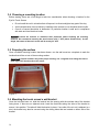
3.5 PREPARING THE SURFACE ............................................................................................................................................ 16
3.6 MOUNTING THE TOUCH SCREEN’S WALL BRACKET ...................................................................................................... 16
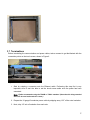
3.7 TERMINATIONS ............................................................................................................................................................ 17
3.8 MOUNTING THE TOUCH SCREEN ................................................................................................................................... 18
3.9 REMOTE ACCESS ......................................................................................................................................................... 19
4.0 EYEON HARDWARE SETUP.................................................................................................................................... 20
4.1
AUDIO: NUVO CONCERTO AND GRAND CONCERTO SYSTEM (010001).............................................................. 20
4.1.1 System Overview ................................................................................................................................................. 20
4.1.2 Configuring the Nuvo Concerto and Grand Concerto........................................................................................ 20
4.1.3 Suggestions ......................................................................................................................................................... 21
4.2 AUDIO: RUSSOUND SYSTEM (010003)....................................................................................................................... 26
4.3 AUDIO: NUVO T2 TUNER (020001 - 020003)............................................................................................................. 27
4.4 AUDIO: INTEGRA DPC 8.5 (030001).......................................................................................................................... 30
4.4.1 IR Setup from Nuvo Keypad control .................................................................................................................. 30
4.4.2 Resetting DVD player ........................................................................................................................................ 30
4.4.3 EyeOn Remote IR Code ..................................................................................................................................... 30
4.5 MEDIA SERVER: DELL OPTIPLEX 755 (130001) ...................................................................................................... 31
4.6 VIDEO: CHANNEL PLUS SVS-88 S-VIDEO MATRIX SWITCHER (040001).............................................................. 32
4.7 VIDEO: KEY DIGITAL FATBOY SWITCHER (040002) ................................................................................................. 33
4.8 VIDEO: KRAMER 7000 PROTOCOLS (040003) ............................................................................................................ 33
4.9 VIDEO: LOCAL VIDEO SOURCE (040004)................................................................................................................... 33
4.10 SECURITY: ELK M-1 (050001) .............................................................................................................................. 34
4.11 SECURITY: WEBRELAY (170001)........................................................................................................................... 42
4.12 CLIMATE CONTROL: RCS TR40 (060001) ........................................................................................................... 43
4.12 SURVEILLANCE: URL (070001) ........................................................................................................................... 45
4.13 SURVEILLANCE: PC DVR (070002) ..................................................................................................................... 45
4.14 LIGHTING: INSTEON (080002) ................................................................................................................................ 46
4.15 LIGHTING: LUTRON (080003)................................................................................................................................. 47
4.16 LIGHTING: LEVITON (080004) ................................................................................................................................ 49
4.17 LIGHTING: LEVITON Z-WAVE (080005) ................................................................................................................. 50
4.18 IR: JDS (090001)....................................................................................................................................................... 51
4.19 IR: OCELOT (090002) ................................................................................................................................................ 53
2
4.20 UPS: APC (140001) .................................................................................................................................................. 54
4.21 POOL/SPA: JANDY AQUALINK POOL (150001) ........................................................................................................ 55
4.22 TOUCH SCREEN: WINXP PRO 400MHZ (100001)................................................................................................. 56
Pre-wiring requirements............................................................................................................................................... 56
4.23 VIDEO HARDWARE: JVC RS232 DVD/VHS ....................................................................................................... 58
4.24 ACCESS CONTROL (120001) ...................................................................................................................................... 59
5.0 WIRELESS CONFIGURATION ................................................................................................................................ 61
6.0 ACCESSING ADMINISTRATOR SCREEN............................................................................................................. 62
6.1 PROFILE ....................................................................................................................................................................... 64
6.2 ROOMS......................................................................................................................................................................... 66
6.3 AUDIO.......................................................................................................................................................................... 68
6.3.1 Nuvo.................................................................................................................................................................... 69
6.3.2 Russound Sound.................................................................................................................................................. 69
6.3.3 Media Server....................................................................................................................................................... 70
6.4 VIDEO .......................................................................................................................................................................... 71
6.4.1 - Managing Remotes ............................................................................................................................................ 72
6.4.2 For IR.................................................................................................................................................................. 72
6.4.3 Learning Codes.................................................................................................................................................. 73
6.4.4 Configuring RS232 ............................................................................................................................................ 75
6.4.5 Proactive Monitoring......................................................................................................................................... 75
6.4.6 Volume Overrides .............................................................................................................................................. 76
6.4.7 Advance Video Setup.......................................................................................................................................... 79
6.5 SECURITY .................................................................................................................................................................... 83
6.6 WEBRELAY ................................................................................................................................................................. 87
CLIMATE CONTROL ............................................................................................................................................................ 88
6.7 SURVEILLANCE (PC DVR) .......................................................................................................................................... 89
6.8 LIGHTING ..................................................................................................................................................................... 90
6.8.1 Insteon Lighting .................................................................................................................................................. 90
6.8.2 Leviton Lighting.................................................................................................................................................. 94
6.8.3 Lutron Lighting ................................................................................................................................................... 95
6.9 IR ................................................................................................................................................................................ 97
6.10 ACCESS CONTROL ..................................................................................................................................................... 98
6.11 SCREEN/PDA............................................................................................................................................................. 99
6.11.1 Quick Screen ................................................................................................................................................... 101
6.11.2 Advanced Commands...................................................................................................................................... 103
6.12 SETUP ...................................................................................................................................................................... 104
7.0 CONFIGURING CISCO ROUTER .......................................................................................................................... 109
7.1 LIMITED FUNCTIONALITY .......................................................................................................................................... 109
7.2 PORT FORWARDING ................................................................................................................................................... 110
8.0 MISCELLANEOUS INFORMATION ..................................................................................................................... 111
8.1 SERVER STARTUP SCRIPT .......................................................................................................................................... 111
8.2 IP.CGI ........................................................................................................................................................................ 112
8.3 RS232 DEVICE COMMANDS....................................................................................................................................... 114
8.4 EXTENDING RS232 .................................................................................................................................................... 115
8.4.1 Extending RS232 – Ethernet Adaptor ............................................................................................................... 115
8.4.2 Extending RS232 – Cat. 5 Extender................................................................................................................. 116
8.4.3 Manage Remotes Device Settings .................................................................................................................... 117
8.5 INTERCOM.................................................................................................................................................................. 118
8.6 TOUCH SCREEN CODES .............................................................................................................................................. 118
8.7 EYEON LIMITATIONS ................................................................................................................................................ 119
8.8 COMMONLY USED MOODS ......................................................................................................................................... 120
8.9 ACTIVATE XM RADIO ............................................................................................................................................... 123
9.0 REMOTES................................................................................................................................................................... 124
9.1 EYEON REMOTE SETUP ............................................................................................................................................. 124
3
9.1.1 EyeOn Remote Basics ....................................................................................................................................... 124
9.1.2 System Code Selection Procedure..................................................................................................................... 125
9.1.3 EyeOn Remote Control Specifications.............................................................................................................. 125
9.2 EYEON REMOTE PROGRAMMING ............................................................................................................................... 126
10.0 EYEON SETUP CHECK LIST ............................................................................................................................... 135
4
1.0 Introduction
Follow the steps outlined in this EyeOn Technician Manual to get your system up and running. Use
the Technician Manual and Quick Start Guides to help you through the initial setup process.
Begin the setup process by installing all hardware that is included in your system. Please referrer to
the manufacturers’ specifications and instructions for installing specific subsystems. Some
subsystems may require pre-configuration. For example, the JDS Infrared Xpander by default is set
for 4800 BPS. This device will not work with the EyeOn server until you switch the jumper. For
troubleshooting the Subsystems please contact the manufacturer of the device. For each device in
your system, refer to the corresponding section of the EyeOn Technician Manual for these
requirements.
After all subsystem hardware is setup and installed properly continue to the Administrator Screen
setup. All hardware setup must be complete before you begin setup on the Administrator Screen.
Once all setup is complete the User Screen can be accessed to control your EyeOn automation
system. Information on accessing the User Screen can be found in the User Manual.
5
2.0 EyeOn Server: Quick Start Guide
Before configuring the EyeOn Server, we recommend connecting all subsystem (audio, video, climate,
etc.) hardware first. Please read the specific sections of this manual which apply to the devices that are
being configured. Some devices require special configuration and will require additional setup
2.1 Accessing the EyeOn Home Administrator Screen
Before getting started with the EyeOn Server setup, temporarily reconfigure the TCP/IP settings on
your laptop to be able to communicate directly with the EyeOn Server.
1. Go to Control Panel.
2. Double-click the Network Connections icon.
3. Right click on Local Area Connection icon.
4. Select Properties.
5. Highlight Internet Protocol (TCP/IP) and click Properties button.
6. Write down the current IP settings.
7. Change IP Address to 192.168.130.1.
Note: The default gateway may need to be changed to the router’s setting.
Now that the laptop has been configured correctly, let’s get started by accessing the EyeOn Home
Administrator page.
1. Connect a laptop or desktop computer to the router or switch that is connected to the EyeOn
Server.
2. Open Internet Explorer. (To avoid compatibility issues, we strongly recommend using Internet
Explorer instead of FireFox).
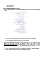
3. Type in the EyeOn Server’s default address in the browser’s address bar:
http://192.168.130.90/website/admin/ or https://192.168.130.90/admin
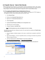
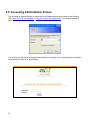
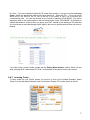
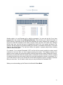
4. Wait for the following screen to appear and enter the following username and password:
6
User Name: admin
Password: ^eyeauto!
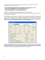
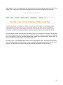
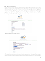
2.2 Configuring the EyeOn Server
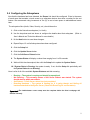
Now that you have navigated to the EyeOn Home Administrator screen, start setting up the EyeOn
Server.
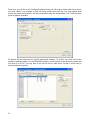
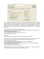
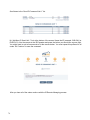
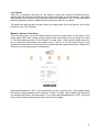
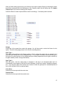
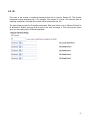
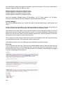
1. Click on the Profile link to bring up the following screen:
2. Use the drop-down boxes to choose the correct model number for each subsystem.
3. Click the Next button at the bottom the screen to save changes.
Notice that the Profile screen also displays the default Unique Name. The Unique Name is a distinct
identifier (in this case, TESTBOX) for remotely accessing the system, so that
https://testbox.eyeonautomation.com can be entered to log on to your EyeOn server. The Unique
Name cannot be edited from this screen. If the preconfigured name is not preferred, refer to the
Customer Resource Center for details about how to customize the Unique Name.
Note: This unique URL will not work on the local network until the router has been configured
correctly. Please see the “About Router Setup” section below for details.
7
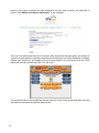
2.3 Activating the Subsystem Links
Once the Profile screen has been configured, the server must be updated by performing the following
steps:
1. Click on the Setup link.
2. Click the Update Server button.
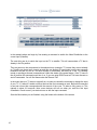
3. Click the Event Log link.
4. Click Detect Hardware link.
Since this is the first time the server will be detecting the hardware, this process can take up to 20
minutes. Once all hardware is detected, future boot times should be anywhere from 2 to 5 minutes.
EyeOn recommends that a monitor be connected to the EyeOn Server to watch for errors as they
occur, but the Installer also has access to this data via the Event Log link. If any hardware has not
been detected, an error message will appear in the Event Log. It is very important to check for errors
in the Event Log when making changes to the system. Make sure all hardware is detected and
running before proceeding to the next section. If a subsystem is not responding please refer to this
EyeOn Technician Manual for help with troubleshooting.
8
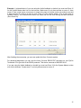
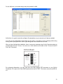
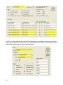
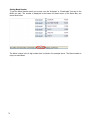
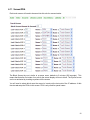
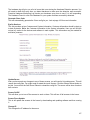
2.4 Configuring the Subsystems
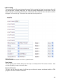
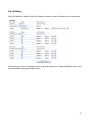
Now that the hardware has been detected, the Rooms link should be configured. Enter in the name
of each room that contains a touch screen or a subsystem device; also enter a number for the sort
feature. We recommend using increments of five (5) so as to leave space to add additional rooms
later.
The subsystem links (Audio, Video, Security, etc.) should be active.
1. Click on the first active subsystem (i.e. Audio)
2. Use the drop-down and text boxes to configure the details about that subsystem. (Refer to
User’s Manual and Technician Manual for more details.)
3. Hit the Next button to save these changes.
4. Repeat Steps 1-3 until all subsystems have been configured.
5. Click the Setup link.
6. Click the Update Server button.
7. Click the Soft Server Reboot button.
8. The System Status will display a reboot time ranging from 1 to 59 seconds.
9. Wait until this time has expired, then click the Setup link to update the System Status.
10. If System Status is Running, the system is ready. If not, click the Setup link periodically until
the System Status shows Running.
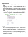
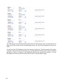
Here is a list of all of the available System Statuses and their meaning:
o
o
o
o
Running – The system is running and should be operational.
Not Running – This normally means a Soft Server Reboot was started. The system
should start up within one minute.
Soft Reboot – A Soft Server reboot has just completed.
Detecting Hardware – The system is starting up. It is going though and finding all
hardware attached to the EyeOn Server (Check the Event Log for current status).
Important! The Administrator screen setup must be complete before the User’s webpage will
function correctly.
9
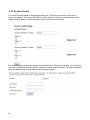
2.5 More about the Setup screen
Though there are several settings under this category, only configure a Username and Password to
get started (refer to the EyeOn Technician Manual for details about the remaining options). The
purpose of this setting is to give the home owner their own username and password for remotely
accessing the EyeOn User Screen. This username will only allow the end-user to access the
EyeOn User Screen, it will not allow them access to the EyeOn Home Administrator Screen. (For
the installer’s convenience, the administrator’s password will give the installer access to both the
EyeOn User Screen and EyeOn Home Administrator Screen.)
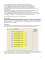
Near the bottom of the Setup page, there are several buttons related to updating and rebooting the
server and touch screens. If you have added or changed devices in the Profile screen, you must click
the Update Server button and Soft Server Reboot for any changes to be recognized. The
Hardware Detection link, within the Event Log, is used to make sure the hardware is registering
with the server. At this point, unless you use the Profile screen to make changes to the hardware
that is already configured and detected, there should be no need to Detect Hardware again.
10
If changes are made to any category, other than Profile, click the Update Server button followed by
clicking the Soft Server Reboot button. When a Soft Server Reboot is performed, the server will
stop responding for up to 59 seconds. Subsequently, the touch screen will also reboot with the new
configuration changes.
Warning! Performing a Soft Server Reboot will cancel all commands. For example if you are
programming lights while you hit Soft Server Reboot the programming process will be canceled.
Important! Even though the server has booted up, it may NOT be finished detecting all of the
hardware. Click the Event Log link and refresh the Event Log page to update the status.
2.6 About Router Setup
We recommend using a Cisco Router or a SonicWall when setting up your router. If a standard router
is being used instead, port forwarding will need to be used. Refer to the Technician Manual for more
details about this subject.
It’s very important to understand that if a Cisco or SonicWall is not used, you will not be able to
access your system using the unique URL through your local network. It will only be accessible from
outside the home. To gain access from inside your home, you need to use the IP Address
http://192.168.130.90/website/admin/ or https://192.168.130.90/admin/ that was mentioned earlier in
the Accessing the EyeOn Home Administrator Screen. Using the internal IP on the local network
will cause the system to have limited functionality (see About Limited Functionality below). If a
Cisco router is being used, please refer to the Configuring Cisco Router section of the EyeOn
Technician Manual for setup instructions.
Note: If the local network has a DNS server the Cisco router or SonicWall will not be necessary.
When the system is connected to the internet it will use a Dynamic DNS server to update the URL
and IP address.
2.7 About Limited Functionality
If you must use the private IP (192.168.130.90) to access your EyeOn User System from inside your
house, you will have limited functionality. The following limitations will only occur with the Surveillance
System and SSL certificate:
•
•
•
You will see a security warning stating that your SSL Certificate is not valid. This does not
mean that your site is not secure; it just means the name does not match the internal IP
address. This warning will not cause your system to run incorrectly.
When using the Camera Button on the EyeOn User screen; the View or Recorded videos will
not be accessible. To access these screens you will be required go to the private IP address of
the Surveillance DVR manually.
If any events have been configured to send pictures to your e-mail address, you will not be
able to access these pictures while on your local network (you will see a red X in its place).
11
2.8 About User Website Access
Accessing the EyeOn system remotely is an important feature of the EyeOn Automation system. This
can be achieved using the unique URL that was created for your system.
If the router is not setup the default IP address is http://192.168.130.90/website/ or
https://192.168.130.90/. However, this will only allow you to access the User Website and
Administrator setup options from your Local Area Network.
To access the EyeOn Home Administrator screen, the IP address on the laptop may need to be
changed to the local subnet. For more details about changing this IP address please see the
Changing Computer IP Address document.
Note: Administrator Screen setup must be complete before the User website can be accessed.
The end-user’s username and password can be created and managed through the Setup link on the
EyeOn Home Administrator screen. This username and password will only work when logging on
to the EyeOn User Screen and will not grant access to the EyeOn Home Administrator screen;
however, the Administrator’s username and password will have access to both the EyeOn User and
EyeOn Home Administrator screen.
For more help with the EyeOn User Screen, refer to the EyeOn User Manual.
12
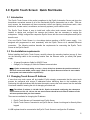
3.0 EyeOn Touch Screen: Quick Start Guide
3.1 Introduction
The EyeOn Touch Screen is the perfect compliment to the EyeOn Automation Server and gives the
homeowner convenient access to all of the functionality EyeOn Automation has to offer. With our
touch screen, the homeowner will have convenient control over lighting, whole-house audio, video
distribution, climate control, surveillance, and security systems, just to mention a few.
The EyeOn Touch Screen is easy to install and, unlike other touch screens, doesn’t require the
installer to design and configure the screens and buttons that are necessary to access the
subsystems. Simply configure the companion EyeOn Server with the correct subsystems and EyeOn
does the rest.
Your new EyeOn Touch Screen is a low-voltage device requiring a 24VDC power supply. It is
designed and programmed to work seamlessly with the EyeOn Server via a standard Ethernet
connection. The following sections describe the requirements for connecting the EyeOn Touch
Screen to the EyeOn Server.
3.2 Pre-Installation requirements
Before installing the EyeOn Touch Screen, carefully choose the mounting location (see pg 4), then
run the following cables to the mounting location from the Ethernet router (or switch) and power
supply.
o
o
16-gauge/3-conductor Cable for 24VDC Power
Category-5 or Category-6 Cable for Ethernet communication
Note: EyeOn recommends adding, at most, a 3-amp inline fuse between the positive terminals of
the touch screen and 24VDC power supply. (Refer to the EyeOn Resource Center for more details
about power and communication requirements.)
3.3 Changing Touch Screen IP Address
If more than one touch screen will be installed, EyeOn strongly recommends that the extra touch
screens be configured with unique IP addresses before delivering them to the installation site.
Performing this step beforehand will eliminate the need to remove the touch screen from the wall after
it has been installed, lowering the risk of damaging a finished wall.
Note: The default IP address is 192.168.130.151. EyeOn recommends configuring the subsequent
touch screens as 152, 153, 154, etc. No two touch screens should have the same IP address as this
will cause problems with your local network.
There are two methods for changing the IP address:
1. EyeOn Touch Screen not Connected to an EyeOn Server
2. EyeOn Touch Screen Connected to an EyeOn Server: Screen Lock keypad or Security Menu
keypad
A USB keyboard must be connected to the EyeOn Touch Screen to configure the IP address.
13
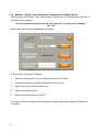
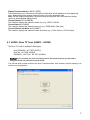
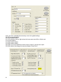
3.3.1 Method 1: EyeOn Touch Screen not Connected to an EyeOn Server
Applying power to the EyeOn Touch Screen before connecting it to an EyeOn Server will result in
the following error message:
EyeOn could not connect to the server, would you like to change your IP settings?
‘Yes’ ‘No’
Please select ‘Yes’ and the Settings menu will appear.
Figure 1
To change the touch screen IP address:
1.
Select the Change button ( you will redirected to the Control Panel)
2.
Navigate to Network Connections and double click on the icon
3.
Right click on the Local Area Network icon
4.
Select the Properties option
5.
Double click Internet Protocol (TCP/IP)
The Internet Protocol Properties window (Figure 2) will appear allowing the updated IP address to
be entered.
14
Figure 2
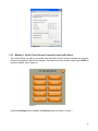
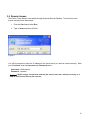
3.3.2 Method 2: EyeOn Touch Screen Connected to an EyeOn Server
The Control Panel can also be accessed from the EyeOn Touch Screen’s interface by using the
Screen-Lock keypad or the Security keypad. Once either has been evoked, simply type 039366 to
access a “hidden” menu (Figure 3).
Figure 3
Select the Settings button to display the Settings screen as shown in Figure 1.
15
3.4 Choosing a mounting location
Before starting, there are a few things to take into consideration when choosing a location for the
EyeOn Touch Screen:
•
•
•
Do not install the unit in a location that will expose it to direct sunlight at any part of the day.
Avoid contamination from insulation by installing touch screens in non-insulated interior walls.
Consult a licensed electrician to determine if a particular location is safe and in compliance
with state and local electrical codes.
Caution! Consult the end-user to determine their preference before finalizing the mounting
locations. We recommend centering the touch screen at 56 ¾” AFF (above finished floor). At this
height, the bottom of the touch screen will be exactly 53” AFF.
3.5 Preparing the surface
Once a suitable mounting location has been chosen, use the wall mount as a template to mark the
location that will be cut out of the mounting surface.
Important! Drywall retainers may affect proper leveling, use a magnetic level along the front or
back edge of the bracket and not the center.
Figure 4
3.6 Mounting the touch screen’s wall bracket
Once the hole has been cut, slide the bracket into the opening with the notched side of the bracket
facing down. If there are no adjacent studs, bend the metal tabs along the sides of the bracket to
secure it into position. The tabs will hold the bracket in place. If one side of the cut-out is adjacent to a
stud, the bracket may also be secured using the oblong holes that are located on either side of the
bracket.
16
Figure 5
3.7 Terminations
Before terminating the communication and power cables, take a moment to get familiarized with the
connection points on the touch screen, shown in Figure 6.
Figure 6
1. Start by crimping a connector onto the Ethernet cable. Performing this step first is very
important, since it won’t be able to set the touch screen aside once the power has been
connected.
Note: EyeOn recommends using the T568-B or T568-A standard. (Note that this wiring standard
must also be used at the switch or router.)
2. Prepare the 16-gauge/3-conductor power cable by stripping away 1.25” of the outer insulation.
3. Next, strip 1/4” inch of insulation from each wire.
17
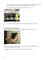
4. After ensuring that each terminal has been loosened enough to accommodate the wire, insert
and secure each wire into the touch screen’s terminal block, as seen in Figure 7.
5. Tug each wire after they are tightened to insure that they are secure.
Figure 7
6. Insert the Ethernet connector into the touch screen’s Ethernet port (shown in Figure 6).
3.8 Mounting the touch screen
Attach the power and the network connections that were discussed in the previous section.
Figure 8
Slide the touch screen into the wall taking care to only put pressure along the border of the touch
screen and not the display surface. (Figure 8)
Congratulations, the touch screen setup is now complete and ready to be tested.
18
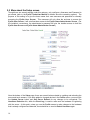
3.9 Remote Access
The EyeOn Touch Screen is accessible through Windows Remote Desktop. To access the touch
screen remotely follow these steps:
1. From the Start menu select Run.
2. Type in mstsc.exe then hit Enter.
Figure 9
You will be prompted to enter the IP address of the touch screen you want to access remotely. After
you hit Connect enter the Username and Password below.
Username: Administrator
Password: ^eyeauto!
Caution! EyeOn strongly recommends restarting the touch screen after remotely accessing it, in
order to avoid inconveniencing the customer.
19
4.0 EyeOn Hardware Setup
4.1 AUDIO: Nuvo Concerto and Grand Concerto System (010001)
The following information is only meant to supplement the manufacturer’s documentation and is
based on the assumption that the Installer is already familiar with installing and configuring the Nuvo
Concerto, Grand Concerto, and keypads:
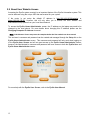
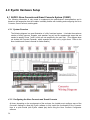
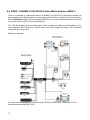
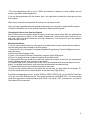
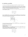
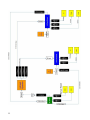
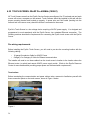
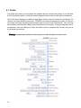
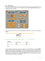
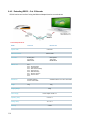
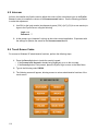
4.1.1 System Overview
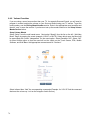
The following diagram is a great illustration of a fully functional system. It includes the maximum
number of audio sources, keypads, and speakers as well as the supplemental amps that are
needed to amplify Zones 7 and 8, which are not amplified by the main unit. (This diagram does
not include the Concerto Expander, which expands the main unit by eight zones. Refer to the
Nuvo Installer and Owner’s manual for further details.)
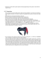
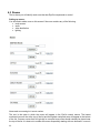
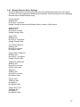
4.1.2 Configuring the Nuvo Concerto and Grand Concerto
At times, depending on the requirements of the end-user, the Installer must configure some of the
Concerto’s settings to allow the EyeOn software to fully exploit the functionality of the Concerto.
Here is a quick tutorial (with EyeOn related tips) about using the Nuvo Concerto Configurator
software
20
• The Nuvo Concerto audio system requires internal programming for the system to work with the
EyeOn Server.
4.1.3 Suggestions
• First, you will have to know which rooms in the house have speakers. If you have one area that is
close together sometimes it is better to combine four speakers into one zone, but never more than
four.
• You should have all the wires labeled for each room.
• Remove the green terminals from the back of the Concerto Unit.
• You can screw one or two wires in each slot in the terminal block.
• If you have over more than eight zones you must use the Concerto Expander.
• These two units are very simple to link together, simply follow the instructions with the unit.
• You need to install the Nuvo software on your PC. The PC must have .Net 1.1 and a RS232 port.
You should install version 1.6 then upgrade to 1.71. The upgrade is on the CD.
• There will also be six sources that come into the Nuvo unit. To take advantage of the EyeOn
doorbell and voice feedback system you must plug source six into the output of the server. You
will use a Stereo Mini (1/8") Male to Two RCA.
• You will need to know where the other five sources are coming from, i.e. XM Tuner, FM/AM/WX
Tuner, CD Player, to set the sources in the Nuvo software.
• If you are using zone seven or eight you will need to use another AMP to power these. Sometime
we will use zones seven or eight to power another receiver in another room. For example, if you
have a room surround sound system you can use zone seven with another Stereo Mini (1/8") Male
to Two RCA cable to put into input two. This way the home owner can switch to input two on their
room receiver and hear anything from the sound system that is being played on Zone seven. A lot
of times we will set Zone seven up as a slave to a near by zone so you can use the control panel
from the near by room to change the source you are listening to.
21
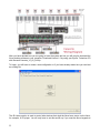
After you have decided how you are going to have the system laid out you will need to download the
Nuvo desktop software to your computer. Download Version 1.6 by using your EyeOn Technician CD
with filename Concerto_V1_60_Full.zip.
To begin, you will have to create a new configuration or if you have already started one you can load
an existing file.
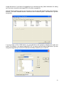
The IR Library section is used to control other devices that might be linked as a source on the Nuvo,
for example, a CD player. You will only have to set this section up if you want the Nuvo keypads to
22
control that source. If you have no keypads then you can skip this step. (More information for setting
up IR devices is located in the Integra DPC-8.5 section on page 30.)
Use the Source section to set up your sources. If you are using the EyeOn system as an intercom,
doorbell, or for audio feedback Source 6 should be set to Intercom System. The Model and Type are
just generic.
If you are using a CD or DVD device, you can add this to the system by selecting the make and
model. For example, if you had an Integra DPC 8.5 you would use the following: Make sure if you are
using the Integra that you use the IR code that is already created for you on the CD.
23
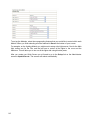
(Notice the gain, some devices put out less output than others. You can use this to have Nuvo
broadcast the source at a louder volume.)
If you are using the server intercom system, please set source 6's gain to +12.50.
If you are using a FM/AM/WX tuner, we recommend using +1.25.
If you are using a XM tuner, we recommend using +4.00.
If you are using the DPC 8.5, we recommend using +1.25.
If you want to utilize Macros, please see the Nuvo Concerto Owner's manual.
Please set up the Zones that are used throughout the house. Each zone should be the name of the
room the speakers are placed in.
When setting up each Zone, enter the name of the room the speakers are placed in. Please make
sure that Volume Reset at Zone On, Loudness compensation On, and Open source control are all
checked to on. If these options are not selected it is possible that the Audio System will not function
correctly. If you are using IR distribution though out the house and want to make each keypad an IR
receiver then uncheck the disable IR boxes. All sources should be enabled.
If you are using keypads the first time the Concerto is turned on, it will ask you what zone should be
assigned. Please match the zones you set on the keypads with the appropriate room. If you choose
the wrong zone number you can change this by holding the menu and up/down volume buttons at the
same time. It is best to set up the Zones before you turn on the keypads.
24
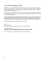
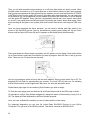
Example 1: (pictured below) If you are using the Audio feedback or doorbell you must use Zone 16
for the System Master take over for the intercom. Make zone 16 only have access to source 6. Here
zones 1-6 are normal zones, zone seven is output to the input of a home receiver in another room and
a slave of zone six, which is a near by room. Zone 16 is the system master, 20 is a slave zone to
Outside (Zone 5). Two controllers are used, one inside and one out, both serving the same functions
(Zone 5 and 20).
After finishing the zone setup, you can now update the Nuvo Concerto system.
For advanced diagnostics you can view the Nuvo Concerto RS232 PDF document on your EyeOn
Technician CD to get a list of the RS232 protocols. This device connects at 9600 BPS 8-N-1.
If you are using the Audio feedback or doorbell you must use Zone 16 for the System Master to take
over for the intercom. Create zone 17 and only allow access to source 6.
25
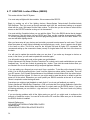
4.2 AUDIO: Russound System (010003)
The Russound audio system does not requires internal programming for the system to work with the
EyeOn Server. You will have to know which rooms in the house have speakers to program the EyeOn
administration screen. If you have one set of speakers that will be installed in close proximity to
another, it is better to group these four speakers into one zone. This grouping can be achieved by
connecting two of the speakers to the left channel and the other two to the right channel, limited to a
maximum of four speakers per zone to avoid overheating of the amplifier. Also, the manufacturer
recommends that no more than three zones should have two sets of speakers attached to their output
(Check Russound Specs for exact detail on grouping). In order to ease final termination of the
amplifier outputs, it is best that all wires are labeled for each room. If you have more then one Russound controller you will need to setup the controller ID. By default
they are all set to 1. You will need to adjust each controller in order; 1,2,3,4,5,&,6.
Before attempting to communicate with the EyeOn server, check that the dip switch next to the RS232
port is in the middle position (RUN). In addition, any other compatible Russound controllers will need
to be connected to the RNET RJ45 port.
If the CAV model is installed, be aware that it does not have a built-in tuner so just disregard this
setting in the Source setup on the Admin screen. When configuring the tuners make sure the tuner
number refers to the source number. For example if you setup the FM/AM on Source #1 you must
also setup the tuner for Tuner #1. This method is Russound’s standard setup. Also on the CAV, make
sure the switch in the front of the unit is in the front or rear position for the RS232 port, depending on
what port you are using.
If the doorbell or whole-house paging option is desired, take note that these options are not available
with the CAM6.6, given that the CAM6.6 does not include a paging port.
If the announcement option is configured, make sure each zone is tested for sufficient loudness. A
good starting point is 40% volume.
If using the CAV model and the doorbell feature is desired, the paging control input needs to be
excited with a 12VDC trigger. This voltage will need to be controlled through an isolated relay on the
ELK security system or PLC output. To setup this EyeOn option, locate the output under the Security
Admin Screen and the Announcement option in the drop down. This setting will cause the relay to
activate when the doorbell is pressed and deactivate once the doorbell tone finishes playing (duration
depends on length of WAV file chosen for custom doorbell sound).
Be aware that for the All commands to work you must have Party Mood enabled. This is enabled by
default.
There are a total of six source inputs available on the Russound unit. In order to take advantage of
the EyeOn doorbell and voice feedback system, connect the speaker output of the EyeOn server to a
source on the Russound (Source 6 is recommended). To make this connection, use a stereo mini
(1/8") Male to two RCA male connectors. Another Y-cable, female RCA to two male RCA, will be
needed to feed this audio source to the Paging Audio In input. To achieve this purpose, connect the
right side of the incoming audio cable on Source #6 to the female input of the Y-cable, connect one of
the male ends to the Source #6 Audio In, and connect the other male end to Paging Audio In. This
procedure results in Source #6 being used for room feedback while the Paging Audio In will be used
for doorbell and whole-house feedback.
To change the follow these steps:
26
Display Preference Mode (3.DSPLY PREF)
This mode allows you to choose how XM channel information will be displayed on the keypad and
tuner. Appropriate button presses access the next or previous preference item.
Note: For any display configuration, the artist’s name and song title will scroll before the display
returns to the designated display format.
Channel Number (CH NUMBER:)
This selection displays the channel number only (e.g., XM070, XM103).
Channel Name (CH NAME:)
This selection displays the channel name only (e.g., ESPN Radio, Real Jazz).
Channel Number and Name (#:CH NAME:)
This selection displays the channel number and name (e.g., 64:The Groove, 121:Fox News).
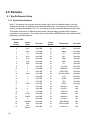
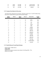
4.3 AUDIO: Nuvo T2 Tuner (020001 - 020003)
The Nuvo T2 Tuner is available in three types:
Dual FM/AM/WX - NV-T2DF (020001)
Dual XM - NV-T2DX (020002)
FM/AM/WX - XM Tuner - NV-T2FX (020003)
Caution! If you are using one of the new T2G tuners for the Grande Concerto you will need to
downgrade it with T2G_Conversion.zip on the CD.
You will start with a screen similar to the Nuvo Concerto screen, then choose to load an existing or to
create a new configuration.
27
From here, you will be on the Configurator screen where you will need to select which Nuvo device
you have. Below is an example of what this setup screen could look like. You must specify what
source the tuners are hooked to. We also recommend using the “Automatically Turn Tuner On when
power is applied” checkbox.
All presets will be setup from the EyeOn web-based software. To do this, you must first set the
presets to a default station. For the FM/AM/WX presets, you should set up the name as a space and
just leave it on 87.90. You only have to do the first five for each tuner, as that is all the user is
currently allowed to specify.
28
For the XM tuner, you should simply setup the presets for XM1.
At this time, it is good to save the configure file somewhere so you can work on it later as needed.
You will need to download the information into the tuner. If you have an error message while doing
this try power cycling the tuner. Also try just doing side A then side B one at a time.
After you have finished the installation, there is one more necessary step for the Concerto system to
communicate with the T2 tuner. You must run a Cat5 cable from the back of the T2 tuner to the EZ
Port Cat-5 Connector.
For advanced diagnostics, you can view Nuvo NV-T2DF RS232 PDF document on your EyeOn
Technician CD to get a list of the RS232 protocols for the NV-T2DF. This device connects at 9600 8N-1.
29
4.4 AUDIO: Integra DPC 8.5 (030001)
There is no software to communicate with the Integra DPC-8.5, six-disk DVD player. All that is needed
for the EyeOn system to communicate with this device is to plug it into the server with a RS232 cord.
If you are using any of the supplied Nuvo keypads, you must program in the IR commands to give the
keypad the ability to start, stop, skip, etc.
To view the DPC-8.5 Owner's manual use your EyeOn Technician CD to view the file DPC85.
4.4.1 IR Setup from Nuvo Keypad control
Again if you are not using any of the Nuvo keypads you do not need to do this. The touch screen will
control this device with the RS232 commands. If you are using Nuvo keypads, you can grab the
Integra IR file off of the CD and put it into your Concerto IR Library (c:\program
files\Nuvo\Concerto\Library) Then you must delete the source for the CD player and add it again.
Setup all the macros. Make sure you have an IR cable from the Concerto and the CD Play IR In.
Test!
If this is a new CD player you need to use the Nuvo Concerto software to add these IR commands
into the system. You will have to have a Nuvo Concerto IR Learning Station to perform the following
steps.
Plug rs232 from learning kit to laptop. Make new device and model. Keep default on IR code. Learn
in each code. Then go back to Concerto and delete the source if it is already added. Then add the
source and setup the macros. Make sure you have an IR cable from the Concerto and the CD Play
IR In. Test!
For advanced diagnostics you can view file Integra DPC 8-5 RS232 on your EyeOn Technician CD
to get a list of the RS232 protocols. This device connects at 9600 BPS 8-N-1.
In the past we have had many DPC DVD players start to skip, pause on their own, etc. This is not
caused by IR or RS232 commands. This is a problem with the DVD player. Send back DVD player
for new one.
4.4.2 Resetting DVD player
Try resetting the unit by holding down the stop button on the player (not the remote) and the
standby/on button at the same time. The display should read INITIALIZE and when it’s done it will
read COMPLETE.
4.4.3 EyeOn Remote IR Code
The DVD IR code for the EyeOn remote is 025. Look at the remote setup for more information
30
4.5 MEDIA SERVER: Dell Optiplex 755 (130001)
The EyeOn Media Software was designed to enable communication between the Dell Optiplex and
EyeOn System. This must be connected over CAT 5 to the network. The Media Server
communicates over TCP/IP.
31
4.6 VIDEO: CHANNEL PLUS SVS-88 S-Video Matrix Switcher (040001)
There is no software to communicate with the CHANNEL PLUS SVS-88 S-Video Matrix Switcher. All
that is needed for the EyeOn system to communicate with this device is to plug it into the server with a
RS232 Null Modem cable. This is not a regular RS232 cord. It is also recommended that the Channel
Plus be hooked into ttyS0 (The onboard serial port).
The SVS-88 has eight inputs and eight outputs. When hooking your audio and video cables to it you
must remember which inputs are in which number and which outputs are where. We recommend
writing this down as you do it.
Below is an example:
For owner's manual and RS232 protocols view file SVS-88 on your EyeOn Technician CD. This
devices connects at 9600 BPS 8-N-1.
32
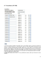
4.7 VIDEO: Key Digital Fatboy Switcher (040002)
There is no software to communicate with the Keydigital Fatboy Switcher. All that is needed for the
EyeOn system to communicate with this device is to plug it into the server with an RS232 cable. This
is a regular RS232 cord
The Fatboy has eight inputs and 4,8,12,16,etc outputs. When hooking your audio and video cables to
it, you must remember which inputs are in which number and which outputs are where. We
recommend writing this down as you do it.
For the 8X4 you must hook up the RS232 and send a CCA01 command. 4800, 8N1
For the owner's manual, view file KDMSW8x4_Manual_HIRES on your EyeOn Technician CD. For
Tech Specs view file KDMSW8x4_Specsheet on your EyeOn Technician CD. This device connects at
4800 BPS 8-N-1.
4.8 VIDEO: Kramer 7000 Protocols (040003)
No configuration software is needed to pre-configure the Kramer 7000. Just connect the RS232 port
to the EyeOn Server’s RS232 port.
You will also have to select the number of Inputs and Outputs. When hooking your audio and video
cables to it, you must remember which inputs are in which number and which outputs are where. We
recommend writing this down as you do it.
4.9 VIDEO: Local Video Source (040004)
There is no software to communicate with the Local Video Source. You will need to select the number
inputs and outputs for this device. This feature can be controlled using the manage remotes feature.
33
4.10 SECURITY: ELK M-1 (050001)
Hooking up the Elk security system is the most in-depth part of the EyeOn installation process. The
Elk controls the in-house security system, opening and closing garage doors, turning touch screens
on and off, routing power to different devises, intercom systems, pool alarm, etc.
The following files can be found on your EyeOn Technician CD.
For the ELK M-1 installation and programming manual view file
M1_Installation&Programming_Manual.
For the ELK user guide view file M1_User_Guide.
For the ELK M1DBH data Bus Hub installation guide view file M1DBH_Data_Bus_Hub.
For the ELK M1TWI Two Way Listen-in Interface installation guide view file M1TWI_2_Way_Interface.
For the ELK M1 LCD Keypad installation manual view file M1KP_LCD_Keypad.
For the ELK M1RB Output Relay Board installation guide view file M1RB_Relay_Board.
For the ELK M1XOVR Output and Relay Expander installation guide view file
M1XOVR_Output&Relay_Expander.
For the ELK M1XIN 16 Zone Expander installation guide view file M1XIN_Input_Expander.
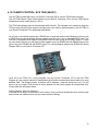
The first part of the Elk configuration will be installing all the input and output devices. For this step of
the process you will have to use the ELKRP M1 SOFTWARE 1.6.10. Use your EyeOn Technician CD
to download the full version, file ElkRP_Full_Install_1_6_10. You will have to plug your computer
directly into the ELK onboard serial port. Or you can enroll these cards through the ELK keypad itself.
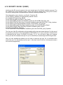
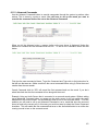
After you have installed the software you will need to setup the com port. Go to connections then
select com port. You will probably use com port 1. After that, select IPconf line. Hit okay and create a
new account (Image below).
34
The Serial Number is located on the bottom of the M1 board. The RP Access Code is very important.
If you lose the RP Access Code you can not make changes to the ELK programming. Make sure you
write down this information.
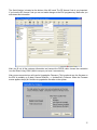
After you fill out all the customer information and connect the RS232 cable, choose the connection
icon and Direct Using COM1 (Which ever port you have it connected to)
After you are connected you will need to Upgrade the Firmware. (This is optional now, the firmware on
the ELK is probably up to date) Choose Send/Rcv --> Update/Verify Firmware. When the Firmware
screen appears simply hit Continue to upgrade the firmware on the system.
35
This will take several minutes to upgrade. After the program is updated you will not be able to
reconnect for a few minuets because the EEPROM is upgrading internally.
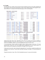
Now that you have upgraded the system it's time to setup the remaining information associated with
the system.
Start by choosing the Users Tab. Here you will setup each user's code. Most houses will only have
one. You will have to contact the home owner to find out what code they'd like to use. You can setup a
temporary code and change it later from the ELK Keypad, we recommend 1234. Since we only use
Area 1, uncheck everything but Area 1.
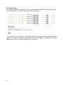
From the user screen you will then move to the Area screen. You will only need to setup Area 1. The
EyeOn system only supports Stay and Stay Instant modes, so uncheck the night modes. Also
uncheck the Single keypress quick-arm checkbox.
36
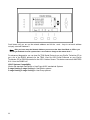
After you have setup the Area's you will need to setup the keypads used in the house. Before setting
up the keypads you will have to enroll them into the system. Each keypad will have an assigned
address. From the factory all keypads are set to address one. Valid keypad addresses are 1 to 16.
The first keypad on the system (Keypad 1) is automatically enrolled upon power up. Each additional
keypad must be assigned a unique address and then manually enrolled from Menu 1 - Bus Module
Enrollment.
(This only has to be done if there are more than 1 keypad)
1) Press and hold the * key, followed by the F5 key. Hold both keys pressed for 5-10 seconds or until
the LCD displays: Exit when done. F1 Set Addr.
2) Press F1 to display current address
3) Set the desired address by entering a number from 1 to 16.
4) Press the Exit key when done.
ENROLLING:
After you have setup all the keypads you will have to Enroll them into the system.
1) Press the ELK key, then press 9 to access the Installation Programming. Press the Right arrow key
to select this menu. The Installer Program Code must be entered to access this menu.
2) Enter the Installer Program Code.
3) The first installer Programming menu displayed will be "Bus Module Enrollment".
4) Press the Right arrow key to select this menu.
5) The M1 transmits an enrollment message to all data bus devices, following by a display showing
the total Bus Modules that are enrolled.
6) Press the Exit key to exit Installer Programming.
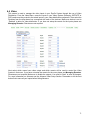
Each Keypad should be setup like the following example. To make the F4, F5 and F6 keys work with
the EyeOn system they must be configured with the following settings.
37
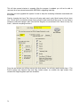
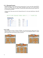
The ELK M1 Main board has 16 zones built on. Expanders can be added to this unit during install. If
there are more than 16 input zones, or you are using a wireless card, right click on the inputs link and
choose New Input Expander or New Wireless Expander.
38
If you are installing a door sensor, use definition 01 and type normally closed.
If you are installing a motion detector, use definition, 04 and type normally closed.
If you are installing a glass break detector, use definition 01 and type normally closed.
If you are installing an outdoor motion detector, use definition 16 and normally closed.
If you have any indoor sensors but shouldn't activate any alarms, set them to definition 16 and
normally closed.
When hooking up the doorbell, choose the Fast loop response, definition 16 and normally closed.
When hooking up garage door sensor, use definition 16 and normally closed.
If you are hooking up a fire alarm detection system, use zone 15 and 16. Zone 15 should be the
power monitoring system. This should be set to definition 16 and normally closed. Zone 16 should be
set to definition 10 and type 5, if it's a four wire system. No attributes for any of these.
It's also important to name each zone for the consumer's logs.
Wireless Setup
Clients may take advantage of wireless technology in their home. To setup the ELK wireless module
right click on the input tab and choose New Wireless Expander. You can only have one wireless card
per unit, they come in 8, 16, and 48 zone cards. Once installed, the zones will work the same as
regular onboard zones. You will have to enroll all the wireless devices after you have uploaded the
system. See below for instructions.
Keyfob Setup
Some users might want to take advantage of a Keyfob to control their system. To allow control you
must setup the keyfob in the Wireless Setup screen. The buttons must be setup as follows.
If you are using a keyfob, you must enroll the fob into the system. See the wireless enrollment at the
below for more information. It is also important to know that the Keyfob will take up one zone on the
wireless system. You will need to set this zone to definition 15-Keyfob.
39
Once you have completed the zone setup, move to the global settings.
G01-05 can remains default
G06-G10 remains default
G11-G12 should be set to 4 digits unless the home owner would like a 6 digit code
G13 remains default
G14-G18 remains default
G19-G25 remains default
G26-G28 If you have installed an outdoor siren to output 2, choose siren output.
G29-G42 needs to be changed to transmit all data to Serial Port 0
40
*The local programming code is set to 172839, this should be changed so other installers can not
access your system at the keypad level.
If you are having problems with the outdoor siren, you might have to switch the wires going into the
ELK output 2.
Make sure you save the configuration file so that you can access it later.
Once you have completed the entire settings configuration you are ready to update the ELK system.
Choose the Send/Rcv icon on the toolbar to send your data to the ELK system.
Changing the User's Code from the Keypad:
After you have setup the software and are ready to let the home owner create their own password for
the security system go to Menu 6 on the keypad. Choose user 1 and let them type in their new 4 or 6
digit code. After they have entered the new code choose exit. You will have to input the installers’
code to access screen 6.
Wireless Enrollment:
If you are using a wireless card you will need to enroll each device into the system after the wireless
card has been setup and uploaded to the ELK system.
1) Press the ELK key, then press 9 to display Installation Programming. Press the Right arrow key to
select this menu.
2) Enter the Installer Program Code.
3) Press 14 to access the Wireless Setup Menu, and then hit the Right arrow.
4) Press 3 to access the learn command, and then hit the Right arrow.
5) Choose which Zone you would like to learn first, make sure to match up the Zone you programmed
into the software with the Zone you learn to the system.
6) Press the Right arrow to activate learn mode. Go to the transmitter and press the tamper or enroll
button. The keypad should emit a short tone when the transmitter becomes enrolled.
7) Continue these steps for all the wireless devices in the house.
(If you are using a keyfob make sure you enroll this onto the zone you setup above for the keyfob. To
enroll the keyfob press the two bottom buttons at the same time (Light & Star).)
For advanced diagnostics you can view file ELK-M1_RS232_PROTOCOL on your EyeOn Technician
CD to get a list of the RS232 protocols. This device connects at 115200 BPS 8-N-1. You must use the
check sum generator to send commands with RS232. Use file M1_CRC_Calculator on your EyeOn
User Manual CD to download.
41
4.11 SECURITY: WebRelay (170001)
WebRelay is an electro-mechanical relay with a built-in web server. It can be controlled via the
Internet or a local intranet. It is very simple to set up and use and has many features. There are 3
types of WebRelay devices that are integrated with the EyeOn Automation system: WebRelay,
WebRelay Dualm and WebRelay Quad.
To begin setup on the WebRelay hook up unit to power and network only. Next setup a computer on
the same network using an IP address of 192.168.1.2 and a Subnet Mask of 255.255.255.0. This will
be used to configure the relay.
Now login to http://192.168.1.2/setup.html with your web browser. (This is the default IP address). The
page is password protected. Enter ‘webrelay’ to gain access. Set the permant IP address in the
configuration page. Next power cycle the relay for the changes to take place. After the relay powers
back on the contacts can be connected. The computer can now be set back to it’s original settings.
The WebRelay can now be accessed using the new IP address.
NOTE:
For the Web Relay
Click “Relay / Input ” and change Relay Options to no local relay control.
For the Web Relay Dual
Click “Relay 1/ Input 1” and change Relay 1 Options to no local relay 1 control.
Click “Relay 2/ Input 2” and change Relay 2 Options to no local relay 2 control.
For the Web Relay Quad you must use Firefox to change the IP address.
.
42
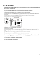
4.12 CLIMATE CONTROL: RCS TR40 (060001)
Use file TR40 Owners Manual on your EyeOn Technician CD to view the TR40 owner's manual.
Use file TR40 Remote Temp Sensor Manual on your EyeOn Technician CD to view the TR40 remote
temperature sensor install manual. (OS21)
The TR40 has software that can communicate with it directly. This software is not needed to setup the
TR40 to work with the EyeOn system but might want to be used for trouble shooting. Use file TR40 on
your EyeOn Technician CD to download the software.
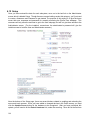
All devices in the climate section use a RS485 bus to send and receive data. Because of this we use
a RS485 hub to bring all climate devices together and then turn it into a standard RS232 input. The
hub has 8 Individual RS485 channels that allow home-run style wiring and a RS232 output. To hook
up more than 8 devices you will have to chain together an 8 port RS485 hub with RS485 output to the
input of an 8 Port RS485 hub with RS232 output. For a wiring diagram please view RS485 Hub Wiring
Diagram PDF on your EyeOn Technician CD.
Once all of the TR40 (For a wiring diagram use your EyeOn Technician CD to view file TR40
Diagram.gif, see owner's manual for install details) and Outdoor sensors have been installed you must
address each. The Outdoor sensor by default will be address 1 and can remain this way. You will
have to go up to each TR40 and set a unique address for the EyeOn system to communicate with.
Please write this information down.
Setting Address, Start with Address 2.
Press the far left button to access the menu section. Once you have entered the menu section press
and hold the two middle buttons until you enter Installers Settings.
43
Scroll down until you are on the network address and hit the + and - keys to set each address
uniquely, start with Address 2.
Note: After you have setup the Network Address you must set the Auto Send Mode to YES or you
will not get feedback from the system when a user makes a change at the remote level.***
For advanced diagnostics you can view file TR40 Serial Protocols on your EyeOn Technician CD to
get a list of the RS232 protocols for the TR40. View file OS21 Serial Protocols on your EyeOn
Technician CD for RS232 protocols for the OS21 Outdoor Sensor. This device connects at 9600 BPS
8-N-1 from the RS485 hub.
HVAC Systems Compatibility
Works with standard Gas/Electric or Heat Pump HVAC mechanical Systems
2-stage Heating, 2-stage Cooling for Gas/Electric systems.
3-stage Heating, 2-stage Cooling for Heat Pump systems.
44
4.12 SURVEILLANCE: URL (070001)
Using this feature will only allow for a direct link to the web based interface of the DVR system. You
will include the URL in the admin setup section. All setup must be configure on the DVR itself and is
not supported by EyeOn.
4.13 SURVEILLANCE: PC DVR (070002)
The PC DVR comes preinstalled from the EyeOn Service Center.
The PC DVR communicates to the server though http commands sent by the Linux server. No RS232
protocols are used.
You must setup a username and password on DVR.
To do this, go into Control Panel, then administrator tools and Internet Information Services. Then
right click on default Website. Click on IIS Password tab. Add the username and password to the
public folder. Make sure this username and password are the same as you setup for access to the
web-based screen. (This is setup on the setup tab)
Setup all the presets for all pan/tilt/zoom cameras. This will be accessible from the touch screen.
The DVR works by only recording when motion is detected. All the motion settings should be setup
out of box. This may not always be the case. You might need to adjust the motion settings to help
capture motion better and trigger the recording. You also can set the DVR to always record, but this
will take up much more disk space.
Make sure you go into the DVR camera names and change the name of each camera to the real
camera name. Most cameras are setup by default as Cam01, Cam02, etc.
•
•
Make sure Remote Desktop is enabled.
The default IP is normally 192.168.130.53.
45
4.14 LIGHTING: Insteon (080002)
Use your EyeOn Technician CD to view the following files.
For Insteon SwitchLinc V2 Dimmer User's Guide view file Insteon-SwitchLinc.
For Insteon SwitchLinc V2 Relay User's Guide view file Insteon-SwitchLinc-Relay.
For Insteon KeyPadLinc V2 User's Guide view file Insteon-KeypadLinc.
For Insteon KeyPad Linc Labels view file Insteon-KeypadLinc-Labels.
For LampLinc V2 User's Guide view file Insteon-LampLinc.
You will need to place two Insteon Access Points throughout the house for maximum Insteon
reliability. It is also recommended to install a Phase Coupler across the 240 line where the dryer is
plugged in.
No setup is required at this point for the lighting system. All of the setup will be done in the Installer's
Screen.
On keypad link you need to make sure all lights are off before you program. If you have an 8 button
you need to fix the B button to turn the light off. Click for 10 seconds, let go then click for 5. Then let
go and click for 5 more. Turn light off then repeat.
However, you might want to connect the 3-ways in the house for ease of the home owners' use before
you will be ready to setup the lighting system (The lighting section can not be setup until the server is
up and running). To connect two switches together, simply press and hold the little set button for ten
seconds of Switch 1. The LEDs on the switch should blink. Hold the on button on Switch 2 for ten
seconds, the light should flash off and on. Now you will have to link the switches the other way. Hold
the on button for Switch 2 for ten seconds until the LEDs are blinking. Do the same to Switch 1. Now
you should be linked both ways. If you want to link 3 or more switches you will have to link every
switch in both directions to make this work properly.
This device connects at 19200 BPS 8-N-1.
You must connect the PLM to the server.
46
4.15 LIGHTING: Lutron (080003)
To view the Lutron RA-RS232 setup guide please view the PDF on your EyeOn Technician CD.
Lutron must first be installed in place of all the light switches you would like to control. The EyeOn
system will only add direct control to each light in the house. All sensors can only be accessed at the
switch level. Once you have installed the lights throughout the house, it's important to setup at least
one repeater. The RA-RS232 will communicate directly with the repeater.
Press and hold the ACTIVATE CONTROLS button on any Repeater until the green CONTROLS LED
turns on (about three seconds).
Once the CONTROLS LED is on, press any button on the RA-RS232 device and all the LEDs will
flutter. The display will flash 01 when the RS232 interface has been activated. If the RS232 interface
fails to respond, consult page 68 in the setup guide.
Once you are done press and hold the ACTIVATE CONTROLS button on any Repeater until the
green LED turns off (about three seconds).
The RS232 interface is now activated.
Setting up each light:
The first thing you will have to do is program every light switch into the repeater before you can
program the individual lights into the RA-RS232 device.
To do so, press and hold the ACTIVATE CONTROLS button on any Repeater until the green
CONTROLS LED turns on. (This should take about 3 seconds.)
47
Then, you will walk around the house and turn on or off every light switch you wish to control. When
the light switch is turned on or off, it should blink two or three times to show you that it was accepted.
After you have programmed all light switches into the repeater you can press and hold the ACTIVATE
CONTROLS button until the green LED turns off (this takes about three seconds). You can easily test
all the switches you just programmed into the repeater by pressing the flash button for a few seconds
until the green LED appears. Every light that is programmed through the Lutron system should flash
on and off. If any switch does not flash reprogram it by holding the controls button down again. When
done checking all the lights on the system press and hold the flash button until the green LED turns
off.
Once you have completed the above activation, you will need to activate each light switch in the
house to the RA-RS232 device. Start by simultaneously pressing and holding the Up and Down
buttons until the Select LED turns ON and U1 appears on the display (about three seconds).
Press and release the Select button repeatedly until U2 appears on the display. Press and hold the
Up or Down button to select the Zone Number you want to program. Start with Zone 1 and go up from
there. There are only 32 zones that can be used.
Now you must assign a switch to link up with this zone address. Simply turn the switch On or Off. The
assigned LED will flash for approximately two seconds. The Level LED will then turn On indicating
that the Zone Number is now programmed. Make sure you write this information down.
Repeat these steps again for the remaining Zone Numbers you wish to assign.
To finish the setup stage press and hold the Up and Down buttons until all the LEDs begin to flutter.
It's important to verify a Zone Number assignment, change the status of the switch by turning it On or
Off. The display will flash d followed by the Zone Number assigned.
Once you have verified all the switches you are now done with the Lutron setup.
For advanced diagnostics you can view file Lutron Radio RA-RS232 Protcols on your EyeOn
Technician CD to get a list of the RS232 protocols. This device connects at 9600 BPS 8-N-1.
48
4.16 LIGHTING: Leviton (080004)
This only works with the Dimension D3208. This is not for the wireless system.
The first thing you most do is set the time on all the Dimensions D3208 or the units will flood the
network. To do this you will click the menu button and scroll up to the Time Wizard. Once here go
through the steps and setup the time. HAI??
Then you will need to setup a panel ID for each Dimension D3208. Go to Menu then setup wizard. Do
the basic setup. Once you get to Panel ID set the Panel ID and save this number.
49
4.17 LIGHTING: Leviton Z-Wave (080005)
This works with the Vizia RF System
You must setup all lights with the controller. We recommend the RZCPG.
Begin by setting up all of the lighting devices. Menu>System Setup>Install Checklist>Include
Dim/Switches> Then you must go through and add each light. We recommend setting up a spread
sheet with the room, light name and the node number. To save time you do not have to create all the
names on the RZCPG controller as long as it is documented.
You must add the Controller before you can add the lights. This is the RS232 device that is plugged
into the server. Plug this device into any RS232 port. Next, put the controller in programming mode.
To access programming mode press and hold programming button until the LED turns Amber. You
can now add each lighting device.
After you have setup all your devices and controller you need to setup areas for each room. This will
allow the system to control lights individually and collectively as a room. Area 1 needs to be all lights
in the home or office. This will be used for the All lights ON and All lights OFF commands. We
recommend setting up the consecutive Areas (rooms) in a logical order from the front of the house to
the back.
You will need to update the controller when you are done. If you make any changes to devices or
areas, in the future, you will need to update the controller again.
You will need to setup each node so the system can get feedback.
Select >Advanced> HAI Setup>Click the Controller>Put a check next to each switch/dimmer you want
feedback from. You will put a check by pressing the + button. Then click the center button when you
are finished. We do not recommend using Lamp and Appliance Modules.
If you are setting up a Keypad you must enroll it as a controller. To do this put the keypad in linking
mode. You do this by pressing button 1 and 3 until the lights turn amber (about 5 seconds). Then use
your RF remote. Go to System Setup>Advance>Yes>Network>Include Node>Click the center button.
This should enroll the keypad. If it does not you might need to reset the device to default or pull the
power off of the switch. Remember you must update your RS232 controller at the end. A soft server
reboot is required to make the keypad work.
Sometimes you might not get feedback on each Light. If you do not get feedback you need to
Select >Advanced> Utilities>Dev Properties> <Find your node that is not giving feedback>>Select the
Node>Click the Assoc button>Make sure that there is a check mark on the RS232 device. If you are
still having problems you can click the – sign and turn it off and save it. Then turn it back on by hitting
the plus sign.
If you are having problems with all the lights coming on and off you might need to rediscover the
network or Update the routes. You need to do this on the RF controller. Make sure you do this where
the RS232 module is installed.
Network Rediscovery
ADVANCED>NETWORK>NTWRK REDICOVERY
Update Routes
ADVANCED>RTS DEVICES>UPDATE ROUTES
50
4.18 IR: JDS (090001)
To download the User Manual and get a list of the RS232 protocols view file JDSManualAndProtocols
on your EyeOn Technician CD.
This device must be changed over to Serial Mode before connected to the server.
1) Remove any static charge from your hands by touching a piece of metal.
2) Remove the two Phillips head screws on the rear panel of the IR-XP2 and carefully slide out the
circuit board.
3) Locate the four jumpers just behind the RS232 jack on the edge of the circuit board.
4) Move jumpers J1 and J2 to the RS232 position.
5) Slide the circuit board back into the enclosure.
6) Replace the rear panel.
7) Connect one end of the provided data cable to the RS232/AUX jack on the rear panel of the IRXP2.
8) Plug the DB-9 Serial Adaptor into any of the RS232 cords on the server.
The rest of the setup for the JDS will be done in the admin setup screen.
For advanced diagnostics you can view file JDSManualAndProtocols on your EyeOn Technician CD
to get a list of the RS232 protocols. This devices connects at 2400 BPS 8-N-1.
You might need to use a Stereo 1/8 MiniJack cable
See the diagram on the following page.
51
52
4.19 IR: Ocelot (090002)
Hook up the Ocelot to the server with RS232. You can add one ADICON 2500 SECU16-IR module to
the system. This will give you up to 16 different IR ports.
You need to make sure you address your SECU16-IR module before you start. It needs to be
addressed as module 0. The addressing will probably happen automatically. If the expander module is
not working you must load the software that came with the Ocelot and click on “attach to controller”
and update the module. This update should happen with a message prompt.
You can use the C-Max Software that comes with the device to configure it. We recommend using
version 2.00 or higher. This is not required because EyeOn will configure the device for you.
Note from Ocelot
“Choosing the right IR code numbers is important: You can use IR codes in two ways with your
Ocelot: They may be learned to be reproduced later by the Ocelot, for the purpose of controlling
equipment under C-Max program control. IR codes can also be recognized by the Ocelot itself as
input events. This gives you one more way to interact with your controller and have it respond to the
IR codes to control devices in your home; be it X10, expansion modules, etc. If you plan on learning
certain IR codes for the purpose of having the Ocelot recognize them as input commands later, store
these in the lower numbered IR code locations. This is because whenever the controller receives an
IR command, it must search through its list of learned IR codes to look for a match, which takes time
and resources. To keep the search time reasonable, there is a controller parameter (parameter #20)
which allows you to specify the maximum code location number to try before giving up looking for a
match. By default this parameter is set to 80. If you need to recognize more then 80 codes, then
adjust parameter 20 to the appropriate higher value. Conversely, if you do not need to match that
many codes, then set parameter 20 to a lower number to speed up the processing of unrecognized
codes. Note: Do not use code location #0 if the code will need to be recognized by the Ocelot.”
EyeOn will automatically setup the parameter. Parameter #20 can be adjusted in the admin screen
under the IR
Set Ocelot parameter #18 to 1 (enable ascii tx on match)
Set Ocelot parameter #20 to the highest location to compare
53
4.20 UPS: APC (140001)
The APC must be hooked up to the EyeOn sever through a USB cord to enable a communication
flow.
54
4.21 POOL/SPA: Jandy Aqualink Pool (150001)
There is no configuration needed on the Administrator screen for the Jandy Aqualink Pool. The Jandy
controller: however, does need to be hooked up to the EyeOn server using RS232 connection.
55
4.22 TOUCH SCREEN: WinXP Pro 400MHz (100001)
All Touch Screens come from the EyeOn Service Center preconfigured. An IP is already set and each
screen will act as a computer on the network. Touch Screens should be installed in the wall with the
proper mounting bracket and hooked up properly. A power wire and Cat5 cable (hooking into the
network hub in the server room) should be all that is connected to the screen.
EyeOn’s Touch Screen is a low-voltage device requiring a 24VDC power supply. It is designed and
programmed to work seamlessly with the EyeOn Server via a standard Ethernet connection. The
following sections describe the requirements for connecting the EyeOn touch screen with the EyeOn
Server.
Pre-wiring requirements
Before installing the EyeOn Touch Screen, you will need to pre-wire the mounting location with the
following cabling:
o
o
16-gauge/3-conductor Cable for 24VDC Power
Category-5 or Category-6 Cable for Ethernet communication
The installer will need to run these cables from the touch screen’s location to the location where the
Ethernet router (or switch) and remote 24VDC power supply reside. (Refer to the EyeOn Resource
Center for more details about providing proper power and communication requirements.)
Terminations
Before terminating the communication and power cables, take a moment to familiarize yourself with
these connection points on the touch screen, shown in Figure 1 below.
Figure 1
56
Start by crimping a connector onto the communication cable, using the T568-B standard. (Note that
this wiring standard must also be used at the switch or router.) Performing this step first is prudent,
since you won’t be able to set the touch screen aside, once the power has been connected.
Prepare the 16/3 power cable by stripping away 1.25” of the outer insulation. Next, strip 1/4” inch of
insulation from each wire. After insuring that each terminal has been loosened enough to
accommodate the wire, insert and secure each wire into the touch screen’s terminal block as shown in
Figure 2, taking care to tug each wire after they have been tightened to insure that they are secure.
Figure 2
Now, simply insert the Ethernet connector into the touch screen’s Ethernet port (shown in Figure 1).
Once this connection has been made, carefully insert the touch screen into the wall mount that was
previously installed.
57
4.23 VIDEO HARDWARE: JVC RS232 DVD/VHS
You must turn off power saving mode.
Make sure you can see the video. Go to setup, Function set up, Display set, Power Save, and then
Off
58
4.24 Access Control (120001)
A computer should be pre setup before it goes on site with the RFID Badge Software. You will need to
set the IP address to be on the local network for the computer. We have set the IP by default to
192.168.130.9. The computer is setup to communicate with 192.168.130.90 by default. If you need to
change this then:
Navigate to the following directory
C:\Program Files\Hitcents\IDBadgeCreator\
Then load Hitcents IDBadgeCreator.exe.config
Change ConnectionString & AccessServer ip address to the corrected IP address.
Once you have done this you will need to setup the username and password on the EyeOn Server.
On the EyeOn Server:
Hit Ctrl, Alt F2 to switch to a clean terminal
Login with username and password
mysql –p
#type installer password
use mysql;
#Change username and password to the correct username and password. You can make this
whatever you want.
grant all privileges on *.* to username@'192.168.130.9'
identified by 'password' with grant option;
grant all privileges on *.* to username@'localhost'
identified by 'password' with grant option;
exit
#Put in the same username and password for database to write logs
pico /home/homeauto/htdocs/datafiles/rfiddatabase.txt
User_Name½Password½
The first time you login, or any time you make a configuration change to EyeOn server for the Doors
you will need to hold control to make the system download the doors to the computer.
NStar Setup
You will need to have 1 NStar Panel per two RFID card readers. You will hook Reader 1 into TS3 and
card reader 2 into TS4. You will need to make sure you hook the ground up.
If you use the iClass cards here is the wire layout
Port 1 =Yellow and Orange
Port 2 =Green
Port 3 =White
Port 4=Black
Port 5=Red
59
On each panel you most address them starting from 1 and going up from there. The first 5 dip
switches are used for addressing. These are setup in binary format. So 1 on all the rest off = 1. Please
refer to the manual for a digram.
Troubleshooting:
If the card is not reading at all then the processor might be locked up on the NStar. You need to do a
full reset. Look in the NStar manual for instructions.
If you card is reading sometime you need to terminate the wires better. Try stripping off more of the
wire in the NStar.
60
5.0 Wireless Configuration
If you are using Linksys Wireless Access Points these steps can help you below. (These steps can
change depending on the firmware version). If you are using a different model please adapted these
steps to your setup.
Configure wireless AP points (one at a time). Make sure only one is plugged in at a time.
Set computer IP to 192.168.1.2
255.255.255.0
Navigate to http://192.168.1.245
Default password is admin. No username
• Go to Wireless/Basic Wireless Setup
o Set ssid to name of home/business (example: Smith)
• Go to Wireless/Wireless Security
o Setup wpa-personal, setup password
Make up a separate password for wireless. (We recommend a different
password for the SSID rather then the EyeOn Password. This way it can be
easy shared)
• Go to Administrator
o Change login password to home/business password.
• Go to setup/Network Setup
o Set ip to 192.168.130.245 (Or whatever IP you are using)
o Default gateway 192.168.130.254 (Or whatever DG you are using)
o Set the next one up the same way, but make the IP 192.168.130.246
Important: If the Cisco Router is not configured then you will not get a DHCP IP through wireless. You
must hard setup your ip address. You could use IP 192.168.130.1, subnet 255.255.255.0, default
gateway 192.168.130.254, DNS 4.2.2.2.
61
6.0 Accessing Administrator Screen
You will need an internet browser to access the secure administrative setup screen at the following
URL: https://192.168.130.90/admin/ or http://192.168.130.90/website/admin/. You will be prompted to
enter your dealer user name and password to access the EyeOn system.
You will then see the EyeOn Automation Administration login page. Just re-enter the same user name
and password to login as an administrator.
62
After logging in, you will be presented with a welcome screen and navigation options for the EyeOn
system. This is where you will set up each component of the system the customer will be using.
This will start your setup for the EyeOn Automation System you are about to configure. By following
this step by step process you should be able to install all the server software as well as set everything
up to a live system. All of the pre-wiring should have already been completed prior to this install as
well as terminated and hooked into the provided equipment.
Now that you’re at the Administration screen, start configuring the server by hitting the Profile link.
(You must begin with the Profile section in order to populate the subsequent sections (Audio, Video,
Security, etc.) with the correct entry forms for the particular subsystems you will be using).
63
6.1 Profile
The profile tab is where you will indicate the hardware that the customer has chosen to use with their
EyeOn Automation system, so that the software program knows to relay to each piece of equipment.
The Profile screen displays your default Unique Name, which is often time referred to as UName. The
UName is a unique identifier (in this case, TESTBOX) for remotely accessing your system, so that you
can simply enter https://testbox.eyeonautomation.com to log on to your EyeOn server. Also, you may
have already noticed that the UName cannot be edited from this screen. If the preconfigured name is
not preferred, refer to the Resource Center for details on how to customize the Uname to suit your or
the customer’s preference.
Warning! Changes made will NOT be saved unless you hit the next button on each screen.
64
Next to each device select the device that corresponds with the individual EyeOn system.
Tuner 2 is used if there is a separate tuner involved in the
IR Send is only used if there is more than one IR device in your EyeOn system.
Note: You must refer to the system hardware or the customer estimate of equipment
specifications.
65
6.2 Rooms
This is where you will identify each room that has EyeOn components to control.
Setting up rooms:
You will need to add a room on this screen if the room contains any of the following:
• touch screen
• audio
• video distribution
• lighting
Name each room and give it a sort number.
The sort is the order in which the rooms will appear in the EyeOn control menus. The lowest
numbered room will be at the top of the list and the highest numbered room will appear at the bottom
of the list. Common rooms that will typically be occupied more often should naturally be placed near
the top of the list. It is best not to number the rooms sequentially starting with one because if a room is
66
added later, all rooms might have to be renumbered. As in the illustration above, sort the rooms using
a range of numbers to avoid having to renumber rooms later.
Be careful to type the room name correctly, this is how it will appear on the customer’s screens. Also
be aware that there is no length limit for naming the room. You should make sure the name is not too
long to fit on the button. Sometimes this requires trial and error with a few names to determine what
will work.
67
6.3 Audio
Use the audio tab to specify audio sources with their respective remotes. Also enable keypads with
their respective zones and set announcement volume levels. (Different Audio system page will look a
little bit different. For example on the Russound page you will not see keypads)
Identify each audio source with a descriptive name. Be sure to select if the source is enabled or
disabled and specify if the source has a remote or not. You must enable the source for it to work;
Sources are enabled by default, so you should disable the source if it is not in use.
If an announcement volume besides the default setting is desired, place a value from 1-78 in the
announcement volume box. One is the highest volume setting while 78 is the lowest setting. The
default volume can be adjusted on the setup tab. See page 103 for instructions.
If the source is Line level, select Yes from the drop down box. You will then be asked to provide mood
numbers for the Volume up, Volume Down and Mute commands. See page 78 for help finding mood
numbers.
Despite the number of zones, Zone 16 will be disabled because it is reserved for doorbells.
68
6.3.1 Nuvo
The NoVo requires you to put which keypads are enabled. You will need to choose to enable or
disable keypads. Choose if there is a keypad or not. Then select the room the keypad is in. If this is
a line level source please select this room has a keypad.
6.3.2 Russound Sound
If you would like to have audio feedback on the Russound please label the source name SERVER.
This will tell the server that is the audio feedback source number.
69
6.3.3 Media Server
If you have a Media Server hooked up to your system and registered in the profile screen you will
see the Media Server Text box at the bottom of the Audio screen.
You must enter in the IP Address of the Media Server and the port number in the format that is
specified. The default IP address and password cannot be changed on the Media Server. Select
Next when you are done making changes to the audio setup.
70
6.4 Video
This screen is used to manage the video inputs in your EyeOn System through the use of Video
Distribution. From the Video Menu, name the inputs in your Video System (Example: SATELITE or
DVD) make sure they match to the actual inputs in your video distribution component. Then select the
Remotes from the drop-down box correspond with each of the devices. Make sure device is set to
“Enabled” to allow for video distribution. If you have not setup the remote for the Inputs please see
Managing Remotes. Remotes are not required.
Next select which rooms have video output and which remote will be used to control the Video
System in that room. If you have not setup the remote for the room please see Managing Remotes.
Remotes are not required. Make sure to enable the outputs. You must hit “Next” to save all changes.
For more information on Advance see the Advance Video Setup Section. Remember to hit the next
button first to save all your inputs before hitting Advance.
71
6.4.1 - Managing Remotes
Managing remotes is used to control input and output devices. You can control them though RS232
and IR. For example, most TV’s have infrared capabilities which allow you to control different
functions of the TV through IR commands. For better results, devices that have RS232 support can
be controlled though RS232.
At the top of the Video screen select the “Manage Remotes” link. Next select Add Remote. Select IR
or RS232
6.4.2 For IR
Name the Remote (example: LG DEN or INTEGRA). The remote will only be visible from the Touch
Screen and PDA. You will not be able to see the remote on the web-based software or mobile
phone. Select which remote layout you want, see below.
TV Source
DVR Source
DVD Source
72
Hit ‘Next’. If you have already learned the IR codes then continue, if not go to section Learning
Codes. Select the appropriate code from the drop down box. Select the Port. * if you are unsure
which port to use Click on the ‘IR’ link at the top of the screen to see a list of devices and
corresponding ports. You can also choose to run a mood by selecting “RUN MOOD”. You will be
required to enter in the mood number in the box below where it says “RUN MOOD.” An Example of
a Mood that would be useful is when you pause your DVD. Instead of just sending an IR command
you could create a mood that brought up the lights in the room so people can see when the movie is
paused.
If you don’t have a mood number, please see the Getting Mood Number section. When you are
done selecting all IR codes/moods hit “Finish” at the bottom of the screen to save your remote.
6.4.3 Learning Codes
To learn codes into your EyeOn system you must be in front of the Infrared Expander. Select
“Setup” from the web based software menu. Next Select “Remote IR” from the menu on the left.
73
Scroll down to the “Send IR Command Unit 1” list.
Hit “Add New IR Send Unit 1” link at the bottom of the screen. Name the IR (example: CAB-CHU or
DVD-PLAY). Aim the remote at the IR Expander and press the button you should see a green light.
You might need to wait a few seconds to hit the remote button. You must repeat this process for all
codes. Hit “Continue” to save the command.
After you learn all of the codes continue with the IR Remote Managing process.
74
6.4.4 Configuring RS232
Begin by naming the remote. The remote will only be visible from the Touch Screen and PDA. You
will not be able to see the remote on the web-based software or mobile phone.
Device
Next select the device you would like to control with the remote. Use the drop down box to see a
complete list. If the device is not in the list then EyeOn is not integrated. Please refer to the
Hardware Integration form on the resource center.
Com Port
The com port is used to communicate with the device. If the device is hooked in to a RS232 port on
the EyeOn Server enter the number of the port. The number should be on the cable coming from
the server. If you are using RS232 Serial over IP enter in the IP address and port number separated
by an ‘!’. (Example 192.168.130.140!10001)
Device ID
A Device ID would be used for identifying different devices. As an example, this is especially helpful
when you have two TV’s on the same com port, you would have the ability to set up different device
ID’s for each of the TV’s. The Device ID’s would be critical in distinguishing between the two TV’s.
For the Device ID refer to page 115 of the Tech Manual.
6.4.5 Proactive Monitoring
Select the check box if you would like to proactively monitor this device. Selecting the box, allows
the system to see if the device responds when it is turned off. If the device does respond, Proactive
Monitoring is recommended. This will allow you to get updates within one hour of a device
malfunction via email. Very often Proactive Monitoring alerts you before the customer even realizes
there is a problem.
If the device does not respond when it is in the off position do not check the box. For example, your
TV will not respond to RS232 when the device is turned off, so this device could NOT be proactively
monitored. Also, you cannot check devices that are already in the Hardware Profile. The device will
not respond if it is in the Hardware Profile.
75
6.4.6 Volume Overrides
If you are using a sound source other than your TV, for example Surround Sound, you will need to
program in moods to adjust the volume on your Surround Sound using your TV remote. To get the
mood number, see the Getting Mood Number section. Enter in the appropriate mood numbers and
then hit “next” to save the remote. If you have not set up the moods continue to the Setup Volume
Moods Section below.
Setup Volume Moods
Select “Setup” from the web based menu. Next select “Moods” from the list on the left. “Add New
Mood”. Begin by naming the mood (example: VOLUP or MUTE). Select which room the Mood will
be associated with. Select “Independent” for the mood option. Select Resettble “NO”. Select “NO”
for Mood Visible option so that the mood will not be visible on the Touch Screen, PDA, Mobile
Software, and Web Base. Add appropriate comments and hit “Continue”.
Select Infrared then “Add” the corresponding commands (Example: for VOL UP find the command
that turns the volume up 1 unit on the Integra or Audio Source).
76
Another option is to use Remotes tab to add the commands. You can only do this if you have
programmed in the remote though Managing Remotes. This will allow you to adjust the volume of
RS232 devices. Depending on how quickly and drastically the volume changes per command, you
may have to add the command to the mood a couple of times and then set a wait timer. Different
devices may vary; use trial and error to determine the best fit for your system and device. For
example, with the Integra we recommend adding the Volume up command 4 times with a 1 sec Wait
Timer for the VOLUP Mood. The wait timer allows the system to properly adjust before sending
another VOLUP command.
For example, if you selected Resettable “YES” and then hit the remote rapidly the volume would
continue to rise even after you have stopped pressing the button. This happens because the
amount of time it takes you to press the remote is shorter than the time it takes to adjust the volume.
Each time you press the button the remote sends a command to turn the volume up 4 times. Instead
of waiting a second, the mood cancels itself and runs again sending the volume up command. So if
you hit the remote 5 times in one second the volume would continue to rise for a couple of seconds
after you were done. You will want to make sure you setup the Mood for Resettable “NO”.
When you are done setting up the Events for the Mood hit Save Mood.
77
Getting Mood Number
To get the Mood Number scroll your mouse over the “Activated” or “Deactivated” link next to the
Mood you want. The number is displayed in the bottom left hand corner of the Status Bar, see
screen shot below.
The Mood number is the 4 digit number that is circled in the example above. The Mood number is
unique to each Mood.
78
6.4.7 Advance Video Setup
Use the “Advance” link to set up the advanced source options. This screen allows you to setup
Moods to override normal video destitution functions. For example, you might want to set up a mood
that turns the TV to the ‘on’ position and to the correct input, lowers the lights and starts a DVD all at
the touch of a button. This will save you the hassle of having to turn on each device individually. If
you do not use the Advance Setup the current remotes will just switch the inputs on the Video
Distribution box. You cannot replace a local source remote when you don’t have a source, which is
hooked up to the Video Distribution, using the same remote.
Select to “Add Source” or “Edit” a source.
First, name the source, then select the source from the drop down box. Next you will have to add a
remote; if you do not select a remote the source will not have a remote next to it. You must add a
79
mood to your source to adjust the video distribution and any other functions you would like to
perform. See “Moods for Advance Video Setup” to set up Moods.
Once you click Add Source there are two options; New Source and Override source. An example of
a source override would be selecting a device that is hooked up to the Video Distribution (example:
Satellite and Cable Box). An example of a new source would be a Local Source such as a DVD
player that is actually hooked up to the TV in the room.
The screen shot above shows what the remotes look like on the Touch Screen after they are setup
and added to the system through the Admin screen.
80
Lock Options
There are 2 checkboxes that give you the option of locking the volume and power functions.
Selecting the first check box will lock the volume and mute button on all of the sources. This means
that no matter which remote you are using the volume will be adjusted on the TV or surround sound
rather than adjusting volume on different sources such as a cable box or satellite.
The power lock uses the same concept. When you select power off on one remote it will turn the
power off for the TV or Projector.
Moods for Advance Video Setup
From the setup screen on the web based software select the moods button. At the bottom of the
screen select “add mood”. Create a mood name and then select which room it is going to be used
in. The Mood Option should be “Room Specific” in some cases. Room specific moods cannot be
run in conjunction with another room specific mood. If you try to run two moods that are room
specific at the same time, the first mood will be cancelled and the second mood will run. Keep this in
mind when you are setting up your mood options.
Select the Resettable as “YES” if you would like the mood to cancel it’s self. One example where
this would be recommended is when setting up a Power On Mood. This is helpful if the device did
not response the first time for some reason. If you did not have Resettable set to “YES”, you would
have to wait until the entire mood ran before you could run it again.
81
In the example above we begin by first sending a command to switch the Video Distribution to the
correct input (Satellite)
The next thing we do is switch the input on the TV to satellite. This will commentate a TV that is
already in the On position.
Then we power on the components in the selected room (example: TV) incase they are not already
on. Toggling can be an issue, to work around this, use discreet IR commands to set up two separate
buttons for on and off. Not all TVs have discreet IR commands, but many do. If the TV is already
turned on sending a discreet command won’t affect the status of the power button. If the TV were in
the off position this command would turn it on. If you are using RS232 most all TVs have discreet on
and off commands. You will find these under the Remote Tab.
In the event that your TV was not originally on, we want to resend the command to change the input
of your TV. If it was off it would not have received the first command we sent. Before this command
is sent set a timer that corresponds with the amount of time your TV takes to fully power on. This
typically is about 6-9 seconds. Note; some devices will turn on when you send the first input
commands. Check to see if your device turns on with the input command.
Save the Mood when you are finished, using the button at the bottom of the screen.
82
6.5 Security
The security is one of the most advanced screens. Start by naming the Areas. In most cases there will
only be one area. Different areas have the ability to operate independently of each other. You will
have to set up every security device that is in the house. Next, name the zone; this is what will be
displayed in the security log. Then select the Area from the drop down box.
Motion Sensor
This is to monitor the status of motion in a particular area.
Door Sensor
This is used to check whether doors are in the open or closed position. This sensor, however, does
not have the ability to open or close the door.
Door Lock Sensors
This is to see the door lock status. It will show you on the touch screen, web-based, mobile or PDA
program if the door is locked or unlocked.
83
Doorbells
This is where the doorbell is wired into the security system. Please select which doorbell you want for
each doorbell (Doorbell 1,2, or 3).
Intercom
This is for the push button of the intercom system. This is only used on the old intercom systems.
Garage Sensor
Put the Garage Sensor and the appropriate sensor name. For example, Garage 1 would be a good
name to keep up with it.
Power Monitor
Always make power monitor zone 15. This is used to see if there is a power loss. The new way of
monitoring power is though a UPS.
Pool Alarm
This is used for the pool sensor.
Photo Sensor
This is used to detect natural light in order to differentiate between day and night.
Other Alarms
This should be used for Zone 16 fire alarm.
Print View
This is so you can print out a list of the Zones to give to the security company for monitoring
AC Locks
This is used for the locks to turn. Lock/unlock them through Access Control. Access Control Locks are
Maglock controlled. Remember you might need to wire up the locks with voltage.
Enable Wireless Key FOB
If they are using the wireless key FOB you must select this option.
Push Button Sensor
This is for using a button as a senor. When the button is pressed the sensor is activated.
84
After you finish setting up the Input you will have to set up the outputs. Begin by selecting the check
boxes that correspond with the Address(es) of the Output(s) cards that are being used. Hit Update
Outputs before you continue setting up the outputs.
Select the Device of each output and then name it accordingly. If necessary select a sensor.
Garage
Select this for the output that controls the garage. You will also need to select the Sensor for this
option. This will tie the garage sensor to the correct controlling device.
Gate Type 1
This option works similar to the Garage option in that it causes the output relay to energize for 5
seconds before falling back to a de-energized state. For most gate controllers, this causes the gate to
fully open for a given amount of time (determined by the delay programmed into the gate controller by
the gate installer), before closing automatically.
Gate Type 2
With this option, once the output relay is energized, it will stay in an energized state until it is
commanded to de-energize by the EyeOn control software (via the touch screen, scheduling software,
etc.). By using this option, the end-user can choose to leave the gate open for extended periods of
time, which is perfect for the occasional party.
Voice Siren
Select this for the output with the voice siren.
Outside Siren
Select this for the output with the outside siren.
85
Touch Screen
This is used to power cycle the touch screens. Select this option for each Touch Screen output.
Announcement
This is used for the Russound audio paging option.
Shade Type 1 (5 sec)
This is used for shades that require different outputs for up and down. You must hook this up by
hooking up the up relay to the first output and the down relay to the output directly under the up
output. This option closes the relay for 5 seconds and then opens it up. Use trial and error to
determine which Shade Type is the best option. Shades require 2 relays: one for the UP command
and one for the DOWN command. The commands must be setup back to back with the UP command
first. Shades will show up on the devices screen.
Shade Type 1 (1sec)
This is used for shades that require different outputs for up and down. You must hook this up by
hooking up the up relay to the first output and the down relay to the output directly under the up
output. This option closes the relay for 1 second and then opens it up. Use trial and error to determine
which Shade Type is the best option. . Shades require 2 relays: one for the UP command and one for
the DOWN command. The commands must be setup back to back with the UP command first.
Shades will show up on the devices screen.
Door Release
This is used for closing doors that are being held open. When the relay is tripped it releases the door
from the open position, allowing it to close.
Relay
This is used for different devices that can be triggered by relays. An example would be a strobe.
86
6.6 WebRelay
When a WebRelay is added to the EyeOn system it shows up under the Security tab, as seen below.
After each type of relay is selected from the drop down box(es) the “Update WebRelay” button must
be selected before the Inputs/outputs can be
87
Climate Control
Use the climate control tab to name and direct the climate controls.
Enable all active climate systems. Select the address the climate is set to. For more information on
this, see page 42. If there is an outdoor sensor include that here as well. An outdoor sensor will
always use Address 1, so any other climates should be addressed starting with 2. Press Next to save
changes.
88
6.7 Surveillance (PC DVR)
1. Put in the private IP address of the DVR. This is so the EyeOn Server can talk to the DVR over
TCP/IP. The normal default IP is 192.168.130.53. Next put in the public domain name and port. An
example is uanme.eyeonautomation.com:8883. Make sure you put :8883. You will find the DVR
security code by logging in to the DVR server and go to c:\inetpub\wwwroot and look for the directory
for the pass code. Should be something like EhitiE9h. Pass codes can also be located in C:\Program
Files\Video Insight\Video Insight Support\. If it is not found in one of those places check the IIS setup.
2. Fill in the appropriate camera(s) name.
3. Enable each camera that is active. If it is a pan/tilt/zoom camera, select yes. Press next to save
changes.
89
6.8 Lighting
6.8.1 Insteon Lighting
This window lists all the lights in each room.
PLM Number
Make sure that you have a 6-digit PLM number at the top of the setup page. If you do not see the
PLM number at the top of this page, you will need to go to the Setup page, click [Event Log], and
click the Detected Hardware link.
Add Master
To add a new master light, click [ADD MASTER] under the appropriate room. Enter a name for the
light, while avoiding the word “light” in the name. Please keep in mind that there is no max length,
but you can easily go over the number of letters that can fit on the touch screen. An average of 1112 letters is a good length.
90
Next, select what type of switch you are programming (i.e. dimmer, relay or keypad).
If you are programming a LampLinc or ApplianceLinc, you will need to choose Program Code By box> and type in the code from the back of the device. When entering the code do not put spaces or
periods between the numbers, as it appears on the device. In other words, if the formatting is
11.22.33, it should be entered 112233.
The next option on this page is Sort. You will be able to sort the lighting list to move a light up and
down in the list on the touch screen, web-based screen, PDA, and mobile device. The lower the
number, the closer the light is to the top of the list. We recommend using intervals of five, so that
any switches added in the future can easily be placed between existing switches in the list.
Now click the Add Light button. Please read and follow the on-screen instructions that apply to the
type of light you are adding. For example, if you are adding a Master Dimmer you will need to press
and hold the reset button on the dimmer switch for 3 seconds until the indicator LED starts flashing
in the ON position. From here you would need to press the Add Light button above the instructions.
The screen that appears will give you information regarding the light that was pressed. Again, click
Add Light at the top to complete the process. If the Add Light attempt was unsuccessful, the status
will appear next to the word “Lighting” at the top of the screen. If a “Device Not Found” error occurs,
hit the Refresh link to retry. If the device still isn’t found, check the Access Points for proper phasing
and then try adding the light again.
Add Slave
If you have a slave switch (a switch that is not the master switch in a three-way, four-way, or fiveway circuit), click the Add Slave link for the switch you want to be its master. Use the drop-down
boxes to choose the slave switch type and program code, which, in this case, should be “Program
Code By Light”. Hit the Add Light button and read the on-screen instructions, as outlined in the
section above.
Delete
The Delete link will simply delete the light. If you delete a light, it is recommended that you reset that
light switch to factory default. If you delete a slave or master, it is recommended that you reset all
the switches in that master/slave group to factory default.
Edit
Use the Edit link to change the light’s name, type, and sorting number. There is also an option to
“Include in all room lights?” which you can use to keep a light from being controlled by the All button
on the individual room and All screens. There’s also an option to Relink To PLM, if the light is not
returning statuses like it should. This button is also necessary for adding KeypadLinc buttons to the
server. This involves editing the light and using the Relink To PLM button to link all of the individual
buttons to the PLM. To make this happen, hit the Relink to PLM button under the Edit screen. You
will need to press and hold each button you are trying to program until it starts blinking. If it says
“Not found” please repeat the process until the button is linked successfully to the PLM.
Important! The button indicator lights must be in the off position when linking the KeypadLinc
buttons to the PLM.
Program
After adding a light, you will need to program it. Programming lights can be a time consuming
process, so please be patient. Time increases exponentially each time a slave is added to a master.
91
In order to save time, after all lights are added, hit the program link on all lights. Lights will be
programmed one at a time, but in a continuous order. This saves the time of having to wait for each
light to program fully before hitting program on the next light.
As shown in the Color Key below, the light will be listed in red until you program it. Once it is
programmed, its status will turn green and, if there are errors, it will turn dark red.
If an error occurs, first try reprogramming the light. If that does not work, try setting it to factory
default, then relink and program the light switch again.
Caution! Although it may be prudent to program the first few lights in a new installation to
insure the integrity of the lighting communications, we recommend that you wait until the end of
the day to click the Program link for the bulk of the lights. One reason is that the reliability of the
programming process is diminished when lights are being operated manually. Another reason
is that the programming time for a moderate-to-large installation can take anywhere from 8-12
hours.
WARNING!
DO NOT DO A FULL REBOOT, SOFT SERVER REBOOT OR DETECT THE
HARDWARE DURING PROGRAMMING. THESE ACTIONS WILL CANCEL THE
PROGRAMMING PROCESS AND ALL CHANGES WILL BE LOST!
Read DB/Show DB
This is used to see if there are problems with the lights. The Show DB option only appears after you
have initiated a Read DB. If you are having trouble with a particular light, this information will alert
you of any possible errors.
General Notes
You need to be very careful with PLC, power line control, interfaces. Anything from fluorescent
lighting to laptop power supplies can cause interference. We strongly recommend that you do not
use PLC lighting controllers in commercial environments, given that they are usually supplied by
three-phase power and have too much electrical noise in the environment for the PLC signals to
overcome. Since the receptacles need to be free of interference, you also need to take great care
when choosing a location for your PLM and Access Points. If you have a server rack plugged into
the same outlet as these devices, you will need to add a 15-amp filter to isolate the rack’s power
conditioning equipment, which can attenuate PLC signals. The same goes for your laptop power
supply. If the PLM or Access Point is plugged into the same receptacle as your laptop, you may
also experience reliability issues.
Run Response Test
This test is used to check to see how well the light responds to commands sent by the EyeOn
server. When running this test, each light will be commanded to turn on and off four times. This test
will show how many times the light switch gives a status response to these series of commands. We
recommend turning on all appliances before starting the test. If you are noticing problems, add
FilterLincs to devices you suspect are causing the interference. To determine what the problem is,
look for electronic interferences near the problem area. Laptops plugged in near PLC lighting
devices have also been found to cause interference with the lighting setup process.
92
Run Status Test
This test is to make sure you are getting good status messages from each light. It also helps you to
double check that you have programmed and named all of the lights correctly. Begin by pressing
Start Over next to Run Status Test. After starting this test, switch each light on and off. This action
should remove the light from the list. Press Test Results next to Run Status Test, to see which lights
are still listed. Locate the lights on the list and test them. Refresh the page to see if the light was
removed from the list. Once they are all gone that means you are getting status from each light.
Also if you forgot to program a light, but turned it off and on for the status check anyway, it will show
up at the bottom of the results page. Unfortunately, since there is no name associated with these
overlooked lights, you will need to determine which lights you missed and program them into the
system.
Important! Always make sure you click on Stop Test at the bottom of the Test Results page when
you have completed your tests. If the test is left running, it will cause more server load and could
decrease the efficiency and speed of the system.
93
6.8.2 Leviton Lighting
Add Master
To add a new master light, click ADD MASTER under the appropriate room. Type a name for the
light. Avoid using the word light in the name. Keep in mind that there is no max length. For aesthetic
purposes, it is recommended to keep the name under 12 characters.
Next select how many scenes you want to use with the Dimensions. Each of these will show up on
the Touch Screen. Enter the group code that you setup on the Dimensions.
The last option is sorting. You will be able to sort the light to move it on the touch screen, web base,
PDA, and Mobile Device. The lower the number is the closer the light is to the top of the screen.
Click Add Light. Read the on screen instructions then click add. If the light is found it will tell you. If it
is not found then try again.
See page 49 for more information on setting up Leviton Lighting.
Edit
Choose edit to reconfigure any of the lighting options or to rename the light.
Delete
This simply deletes the light.
94
6.8.3 Lutron Lighting
95
Add Master
To add a new master light, click ADD MASTER under the appropriate room. Type a name for the
light. Avoid using the word light in the name. Please keep in mind that there is no max length, but
you can easily go over the number of letters that can fit on the touch screen. An average of 11-12
letters is the maximum length.
Next select whether the light is a dimmer or relay switch. Enter the group code that you setup on the
light switch.
The last option is sorting. You will be able to sort the light to move it on the touch screen, web base,
PDA, and Mobile Device. The lower the number the closer the light is to the top of the screen. Click
Add Light. Read the on screen instructions then click add. If the light is found it will tell you. If it is
not found then try again.
See page 47 for more information on Lutron Lighting.
Edit
Choose edit to reconfigure any of the lighting options or to rename the light.
Delete
This simply deletes the light.
96
6.9 IR
First enter in the number of matching commands that will be used for Remote IR. This number
represents a range beginning with 1. For example, if the number is 81 then 1-81 would be used as
matching commands. Generally this number will be between 80 and 100.
The ports listed are used for IR sending commands. Each port will be run to a different IR block for
IR distribution. Enable each port that is going to be used and name it. This name will be shown
when you are setting up the IR Send commands.
97
6.10 Access Control
You should link each reader to the appropriate door lock. The door lock is setup on the security
screen. See page 83. Also select which Relay controls each lock. Access Control software must be
registered and installed on the server before Access Control can be activated.
The Account Setup link gives you access to the screen below. This screen will allow you to setup the
User Name and Password for the EyeOn Automation Access Control Software. This login information
operates independently from the Administrator and User Screens.
98
6.11 Screen/PDA
Each touch screen will need to be saved into this site for communication.
The Black Screen time out, similar to a screen saver, defaults to 5 minutes (300 seconds). This
means that that after 5 minutes of no activity the screen display will turn to black. The EyeOn screen
can be re-activated by touching anywhere on the screen.
You will need to select which room the screen is in and put the last octet of the IP address. At this
time do not setup the PDAs in this screen. PDA is only used for special cases
99
The VoIP through Touch Screen setup is listed below the Touch Screen setup. This will allow you to
setup each touch screen and the corresponding zones. We recommend keeping the names the
same.
You will need the full IP address of the touch screens to set this up. The touch screen will not have
a camera. Once you test the touch screen you can then adjust the volume of the room by overriding
the default. If there is a camera on the standalone intercom you can select the camera. You can
then adjust the volume on this screen but setup is done on the Surveillance page.
100
6.11.1 Quick Screen
Quick Screens allow for fast and easy access to the features you use more prevalently on each
touch screen. Quick Screens can be managed from the Home Administrator Screen and
changed as often as you’d like.
From the Administrator Screen select the Screen/PDA. At the bottom of the screen select Quick
Screen.
All touch screens will be listed. If your touch screen is not listed please see the Screen/PDA
section of the Tech Guide. Select Edit next to the touch screen you want to change. Here the
Module numbers represent the quadrants of the screen. Each module will allow you access to one
component of your EyeOn system. Select the components from the drop down boxes. There is
also a check box that allows you to enable and disable the access to your touch screen. When
you finish making your selections, select Next.
101
To set up the Modules, select the corresponding features that you would like to control within each
Module. When you finish selecting all of the features hit Save at the bottom of your screen.
For example; on the Lighting Module you might want to setup a few light scenes. One for the Main
light, anther one for the Fan, and the last one to control all the lights in the room and the
bathroom. This will allow you to turn on all the lights with a single button press.
After you create your Quick Screen you will need to go to the Setup link on the Administrator
screen to Update Server. The screens will reboot automatically.
102
6.11.2 Advanced Commands
Use the Advance Command button to override commands through the system to perform other
actions. This is done by running a mood. You will have to set up the mood you want to
override the command before you set up the Advanced Command.
When you hit the Advance button, a screen similar to the one above is displayed. Notice the
bottom box contains the last command that was run. To add a new Command, select the Add
button.
First give the new command a Name. To get the Command and Type refer to the bottom box for
the last one that was ran. (Make sure this is the correct command before using it). Enter the mood
number from the user screen.
Cancel Command click for YES, will cancel the first command and run the mood. If you don’t
select the check box the first command will run along with the mood.
Example: Using an Audio Source that is connected to a surround sound system. Without setting
up an Advanced Command when you power on the audio source it will only switch the audio
distribution to the correct output. You will manually need to turn on the surround sound. To fix this
problem you will need to set up an Advanced Command to run a mood that turns the surround
sound on and to the correct port. In this case you would not want to select the Cancel Command
checkbox. This will enable the first command that turns on the Audio distribution to run while also
running a mood to turn on the surround sound.
103
6.12 Setup
Once you have entered the data for each subsystem, move on to the last link on the Administrator
screen which is labeled Setup. Though there are several settings under this category, you’ll just need
to create a Username and Password to get started. The purpose of this setting is to give the home
owner their own username and password for remotely accessing the EyeOn User webpage. This
username will only allow the end-user to get to the User webpage, but will not give them access to the
Administrator screen. (For the installer’s convenience, the administrator’s password will give the
installer access to both the User and Administrator screens.)
Near the bottom of the Setup page, there are several buttons related to updating and rebooting the
server and touch screens. Since you have added or changed devices in the Profile screen, you must
click the Update Server button for the hardware to be recognized. After you have performed this
update, you will need to hit the Detect Hardware link, under the event log. Since this is the first time
104
the server will be detecting the hardware for your new installation, this rebooting process can take up
to 20 minutes. Note: Once all hardware is detected, future boot times should be anywhere from 2 to 5
minutes. Though we recommend that you keep a monitor connected to the EyeOn server to watch for
errors as they occur, the installer also has access to a historical version of this information via the
Event Log link on this Setup page. At this point, unless you use the Profile screen to make changes
to the hardware that is already configured and detected, there should be no need to perform another
Server Reboot.
If changes are made to any category, other than Profile, you will need to click the Update Server
button followed by clicking the Hardware Detection button.
When you do a Soft Server Reboot, the server will stop responding for up to 59 seconds.
Subsequently, the touch screen will also reboot with the new configuration changes.
Important! Even though the server has booted up, it may NOT be done detecting all of the hardware.
Please watch for the following Status information at the top of screen to see the hardware status:
o
o
o
o
Running – The system is running and should be operational.
Not Running – This normally means a Soft Server Reboot was done. The system
should start up within 1 min.
Soft Reboot – A Soft Server reboot has just completed.
Detecting Hardware – The system is starting up. It is going though and finding all
hardware attached to the EyeOn Server.
Doorbell Volume
This will allow you to adjust the doorbell volume for the entire house. Once you have updated the
volume, click the update volume button next to the doorbell volume. Keep in mind that one is higher
and 78 is lower.
Announcement Volume
This is the default Announcement Volume for the entire house. Adjust the volume, then press update.
First Doorbell Source
If you would like to make the doorbell quickly ring in one room first, before ringing in the entire house,
then you can select a room from the drop down. Once you have made the change click the update
button above the drop down box.
Allow Moods
If you would like to turn the mood button off on the touch screen, you can do so by selecting off and
clicking update.
Allow Internet Browser on Touch Screen
If you would like to turn the internet browser off on the touch screen, you can do so by selecting off
and clicking the update button.
HTTP Username and Password
Use these fields to setup the homeowner’s username and password to login to the web-based screen.
Once you have updated, press Save Password. The username and password can only be used for
the user screen not for the admin screen. The admin name and password has access to both.
Longitude & Latitude
105
Use these fields to setup the Longitude & Latitude for sunrise and sunset. This is used in cases where
things are triggered by the sun setting or rising.
Eastern longitude is entered as a positive number
Western longitude is entered as a negative number
Northern latitude is entered as a positive number
Southern latitude is entered as a negative number
Here is an example of Bowling Green, KY #Longitude = -86° 27' West, Latitude = 36° 58' North.
Everyone in North America will have a negative Longitude and positive Latitude.
Sub User Manager
The Sub User Manager allows you to create sub users for the web-based screen, mobile phone, and
PDAs.
Create a new user by giving them a user name and password. Creating a new user will add them to
the user list within the Sub User Manager. Each user will have full access by default.
Press limit access to restrict their access to specific buttons or rooms. Restricting a button or room will
remove their access to control those buttons or rooms. If you select Schedules or Moods from the
buttons, the user will not be able to view the schedule setup screen. Select any buttons or rooms the
user should not have access to control and press save.
This is important to note because if they have access to the Schedule Setup, then they have access
to all schedules and moods. This could pose a serious security risk.
Press delete to delete a sub user. Deleting a user immediately restricts their access.
Event Log
You can use the event log to see if there are any current hardware issues. If there are issues you will
need to restart the server or rerun the startup script. You can also look at the current errors. This will
pool the device once an hour to see if there are any issues. For example, if something gets unplugged
it will stop responding and report an error.
106
The hardware log will give you a list of errors that occur during the Hardware Detection process. You
will need to check this every time you detect hardware to make sure the detection was successful.
Proactive Hardware Monitoring Log checks your hardware every hour to see if it is still responding.
The Hardware Found is a list of the hardware in your system that was successfully detected.
Generate Cisco Code
This will automatically generate the Cisco config for you. Look at page 109 for more information
EyeOn Services
This link provides unique Customer and System information. Customer information should be kept up
to date by dealer. Below the Customer Information is the System Information. Here you will find the
unique key codes for the devices and software in each system. This information may be needed for
activation purposes.
Update Server
After you have made any changes to any of these screens, you will need to hit update server. This will
resave the config files. You might need to restart the touch screens. Click the Screen Reboot button to
do this. You must hit the Soft Server Reboot to reload the config file. The server will be down for about
half a minute.
Screen On/Off
This will allow you to turn off the screens to work on them. This will turn off all screens in the house.
Screen Force Update
This is will update the screens in the house by downloading and updating software and then running
it.
Change IP
This changes the IP address for the server.
107
Change Password
This will change the password on the administrator login screen, the htaccess for web access, and
ssh password for the root user. Things that will not be changed are listed below:
Cisco Router
Touch Screen Computer Login
DVR Computer Login
DVR htaccess Password
Wireless Access Points
All these will need to be changed manually. For more information on changing the computer login info
for the touch screen please see Changing Touch Screen Password.
108
7.0 Configuring Cisco Router
Do this after you insert the touch screen and IPs.
Now you need to setup the Cisco 831 for internet access and DHCP.
Login to the EyeOn Admin Screen
http://192.168.130.90/admin/
Go to setup and Cisco and generate the Cisco configuration and do the on screen instructions.
Make sure it takes the Cry key gen rsa line at the very end. It will only go through when you have
internet access. You have two options, wait for internet access or add a line to the config ‘ip domainname insightbb.com’.
If it does not work, try restarting the cable router, then the 831 router. The 831 takes a while to boot
up. Once it boots up you should get a 192.168.100.1 or 10.X.X.X. Setup DHCP and go to
74.128.1.122 and you need to go through the screens. Once you go through, you must restart 831.
Then it should work.
Once you have internet service, reboot the server and let it install updates if any.
We recommend using a Cisco Router or a SonicWall when setting up your router. If a standard router
is being used instead, port forwarding will need to be used. Refer to the Technician Manual for
more details about this subject.
Important: If a Cisco or SonicWall is not used, you will not be able to access your system using the
unique URL through your local network. It will only be accessible from outside the home. To gain
access from inside your home, you need to use the IP Address http://192.168.130.90/website/admin/
or https://192.168.130.90/admin/ that was mentioned earlier in the Accessing the EyeOn Home
Administrator Screen. Using the internal IP on the local network will cause the system to have
limited functionality (see About Limited Functionality below). If a Cisco router is being used, please
refer to the EyeOn Technician Manual for setup instructions.
Note: If the local network has a DNS server the Cisco router or SonicWall will not be necessary. When
the system is connected to the internet it will use a Dynamic DNS server to update the URL and IP
address.
If you would like to access SSH to the EyeOn server use port 22. If you would like to access the Cisco
Router to the EyeOn server use port 2001.
7.1 Limited Functionality
If you must use the private IP (192.168.130.90) to access your EyeOn User System from inside your
house, you will have limited functionality. The following limitations will only occur with the
Surveillance System and SSL certificate:
•
You will see a security warning stating that your SSL Certificate is not valid. This does not
mean that your site is not secure; it just means the name does not match the internal IP address.
This warning will not cause your system to run incorrectly.
109
•
When using the Camera Button on the EyeOn User screen; the View or Recorded videos will
not be accessible. To access these screens you will be required go to the private IP address of the
Surveillance DVR manually.
•
If any events have been configured to send pictures to your e-mail address, you will not be
able to access these pictures while on your local network (you will see a red X in its place).
7.2 Port Forwarding
Some port settings may need to be adjusted.
This is an example, please change as needed
External Port Number Internal Port Number
22
22
80
80
443
443
Internal IP
192.168.130.90
192.168.130.90
192.168.130.90
We recommend opening the port for remote desktop to the surveillance system.
External Port Number Internal Port Number Internal IP
8883
8883
192.168.130.53 (Surveillance IP)
3389
3389
192.168.130.53 (Surveillance IP)
We recommend opening the port for remote desktop to each touch screen.
External Port Number Internal Port Number Internal IP
3390
3389
192.168.130.151 (Touch Screen 1)
3391
3389
192.168.130.152 (Touch Screen 2)
110
8.0 Miscellaneous Information
8.1 Server Startup Script
Run startup script to detect new hardware from terminal:
Option 1, reboot server
Option 2, Hit Ctrl, Alt F2 to switch to a clean terminal
Login with username and password
Type cd /home/homeauto/htdocs/
Type ./startup.cgi
111
8.2 IP.cgi
The User Screen helps enforce restrictions through use of the Lock and Limit Screen buttons. These
screens allow you to limit which features you can adjust through each touch screen.
For even greater control over your system you can use IP.cgi to restrict things other than rooms and
touch screen. You can restrict things such as Climate, Devices, Security, Intercoms and Cameras.
You must log on to the EyeOn server using SSH. IP.cgi is located: /home/homeauto/htdocs/cgi/IP.pl.
Use a Text Editor to edit this .
It may look similar to the file below. The highlighted portions below must be in the script in order for
your EyeOn server to work.
#This is used for each com port on the system. This is setup before it gets to you.
$TTYS = "\@TTY = (0,1,2,3,4,5,6,7,8,9,10,11,12,13,14,15);";
#To restrict things other than rooms and devices, you can do this though IP.cgi
#Restrict
$RestrictClimate{'151'} = "2:3:4:5:6:7:8:9:10:11:12:13:14:15:16:17:18:19:21:22";
$RestrictDevice{'151'} = "3:4";
$RestrictSecurity{'151'} = "1";
#$RestrictIntercom{'151'} = "1:2";
$RestrictCamera{'151'} = "4:5:6:7:8";
#Put the last oct of the IP where you see 151. Put each reference number of each item in the “.
Separate each one with :. To figure out the reference number you will need to look in Properties.txt.
Below is the reference number in bold.
112
#Reference to each restriction
#Climate
#&ThermostatReferenceNum1=2&
#Devices
#&Device1Name=DETACHED LEFT&
#Security
#&SecurityRefNum1=1&
#Intercom
#&Intercom1ID=1&
#Camera
#&Camera1Num=1&
#for server ip address
$SERVER_IP = "192.168.130.90";
$TTYS = "\@TTY = (0,14,15,44,45,46,47,48,49);";
1; #return true
113
8.3 RS232 Device Commands
You can use these RS232 commands to help with trouble shooting needs.
Device
RS485 hub
with outside
RS485 hub
with temp
JDS
Channel
Plus Video
HD Video
ELK
Cd Player
Insteon
Lotron
Nuvo
Tuner
Russound
Jandy
114
Command
Baud
Rate
Settings Comments
A=1 R=3
9600 8N1
A=2 R=1
6C82C1CC6D
9600 8N1
2400 8N1
MX00Z06
0111
06rr0056
!2PMS01
02 60
NOTING
*VER
*T'A'VER
HEX
#ECHO = ON
9600
4800
115200
9600
19200
9600
9600
9600
19200
9600
8N1
8N1
8N1
8N1
8N1
8N1
8N1
8N1
8N1
8N1
This is if the device is set to 1
This is if the device is set to 2. Note you can
use 255 to talk to all devices
This should work
Chr, can not send
8.4 Extending RS232
8.4.1 Extending RS232 – Ethernet Adaptor
To do this you need to use a device that converts RS-232 to IP. This will allow you to plug this
device to any Ethernet switch and control devices.
We have used NET232-DTE from Gridconnect (http://www.gridconnect.com/net232-dte.html)
The first thing you will have to do is set the IP address of the device. If you use the Device installed
application that comes with the device you can set the IP. After you set the IP you can telnet into the
device to configure it. Telnet <IP> 9999. You will need to change the baud rate, stopbit, etc to match
the device settings.
See Manage Remotes Device Settings for appropriate settings. Settings for the Devices are
normally 9600,8N1. Most of our devices use the default settings.
Additional setup options:
Once you have telnet into port 9999 you will need to setup the security.
Server 0
Change Telnet Password (home)
Channel 1
Change baud rate
Security 5
Disable SNMP Y
Disable Web Server
Disable Web Setup
Save and Exit
Once this is setup you can use this for all the remotes. This can not be used for the main devices on
the system. You can also use this in the advance section of the scheduler software.
If you need more information on the baud rate for each device please referrer to the Device Setup
document.
115
8.4.2 Extending RS232 – Cat. 5 Extender
RS 232 can be ran into Cat 5 using the Minicom Adapter listed on our order sheet.
Technical Specifications
Model
Local Unit
System Cable
CAT5 UTP
Maximum Distance
1000m/3,300ft
Connection
RJ45 System
Jack Power
DB9F-RS232
DB9 Pin Out
Pin 1 Pin 2 - Received Data
Pin 3 - Transmit Data
Pin 4 - Data Terminal Ready
Pin 5 - Signal Ground
Pin 6 - Data Set Ready
Pin 7 - Request To Send
Pin 8 - Clear To Send
Pin 9 -
Dimensions
23Hx45Dx75Wmm /
0.91Hx1.77Dx2.95W"
23Hx45Dx75Wmm / 0.91Hx1.77Dx2.95W"
Weight
120g
120g
Shipping Weight
Power Supply
RJ45 System
Jack Power
DB9M-RS232
680g
Power Adapter 12VDC 1A
Operating Temp
0° to 40° C
Storage Temp
-40 - 70° C
Warranty
116
Remote Unit
3 Years
8.4.3 Manage Remotes Device Settings
The device settings are used during the initial setup for programming the devices in your system.
The device ID is very important for identifying the component. Use the following ID for the Managing
Remotes tab on the Administration setup.
LG Plasma/LCD
9600bps, 8N1
Device ID is 1 by default
Straight Through on some and Null Modem Cable on others. Check manual.
Integra DCP 8.5
9600bps, 8N1
Device ID is not used
Straight Through Cable
Integra DTR
9600bps, 8N1
Device ID is 1 by default
Straight Through Cable
JVC RS232 DVD/VHS
9600bps, 8N1
Device ID is not used
Null Modem Cable
Pioneer Elite 1150HD½2½
9600bps, 8N1
Device ID is ** by default
Straight Through Cable
SunBriteTV SB4600-HD
9600bps, 8N1
Device ID is not used
1/8 Mini Jack Cable
ViewSonic
9600bps, 8N1
Device ID is not used
Null Modem Cable
InFocus IN83
19200 bps. 8N1
No default id
Null Modem Cable
InFocus IN72,74,76
19200bps, 8N1
No default id
Null Modem Cable
117
8.5 Intercom
At times, the installer may find the need to adjust the volume of the microphone input on the EyeOn
Server in order to increase the volume of the Announcement feature. Use the following procedure
to make this adjustment:
1. Use SSH or the local console (simultaneously press [CTRL]+[ALT]+[F2] for a new session) to
logon to the EyeOn Server using the following:
Login: root
Password: ***
2. At the prompt, type “alsamixer” to bring up the volume control application. Experiment with
the settings to optimize the sound for the Announcement feature.
8.6 Touch Screen Codes
For access to Windows XP administrative functions, perform the following steps:
1. Press the Security button to invoke the security keypad.
o If the Screen Lock Keypad is already being displayed, go on to the next step.
o If the Security button is not present, press the EyeOn Logo to return to the Main Menu.
2. Type in the following code: 039366
3. The following screen will appear, allowing access to various administrative functions of the
touch screen.
118
8.7 EyeOn Limitations
Though the EyeOn Server is extremely flexible and can be used in most home automation
installations, there are limitations to keep in mind as you design your EyeOn Automation based
system. These limitations are listed below:
•
•
•
•
•
•
•
•
•
•
•
•
•
•
•
•
•
38 Rooms
o Following Devices linked to room
Audio
Intercom
Lighting
Video
Touch Screen
8 Input and 20 Output HD Video Distribution, plus
8 Input/Output Standard Video Distribution
25 Touch Screens w/ Intercom
o If you have a gate intercom, door intercom, etc will come out of the 25
34 Touch Screen
200 scene max Insteon
5 Audio Source Plus 2 Aux ports
30 Audio Zone
o 15 Audio Wall Key Pads
60 speakers or 90 speakers doubled up.
38 rooms of light or extra lights be added to other rooms
16 Camera Systems for touch screen viewing
32 Camera System, plus
32 HVAC (Easily expanded)
15 RFID Access Control Readers
IR supports up to 20 different ports
o Can run same port to multiply IR emitters
You are allowed three different doorbells.
o If you have more than three you can run them in parallel, but you will hear the same
doorbell for both doors.
o You can also make a an intercom a doorbell It will just show up in the intercom screen,
but work like a doorbell.
You are allowed five external intercoms.
119
8.8 Commonly Used Moods
Some event sequences must be setup as a mood to function appropriately. There are many reasons
to make triggers run moods to help change the way the event will act. One advantage of making it a
mood is simply because it can be ran from the touch screen. If you are setting up a mood to run on an
Insteon keypad, it is best to make the mood from the mood screen and make the trigger on the
keypad to run that mood. Automation is all about doing things automatically. It is best to try and use
different sensors and schedules to do task automatically.
These are quick examples of commonly used moods that you may want to set up.
•
•
•
120
Main Moods
o Night Mood
Turn on lighting, set security alarm, wait, turn off all lights in typically
unoccupied areas- i.e. kitchen, etc.
• Make this a mood, room specific, resettable no
o Day Mood
Turn on all lights in occupied rooms/areas
• Make this a mood, room specific, resettable no
o Party Mood
Turn on all lights and music in occupied areas
• Make this a mood, room specific, resettable no
o Away Mood
Turn on all lights, turn off all music, set security system, wait, turn off all lights in
house
• Make this a mood, room specific, resettable no
TV Moods
o Movie Mood
Turn off lights
Send IR to turn on equipment
• Make this a mood, room specific, resettable no
o TV Mood
Turn off some lights and dim others
Send IR to turn everything on
• Make this a mood, room specific, resettable no
o Sports Mood
Turn off some lights and dim others
Send IR to turn everything on, turn up sound system
• Make this a mood, room specific, resettable no
Misc Moods
o Hot Tub Mood
Turn on lights outside, make some lights dim & turn up music volume, wait, turn
off lights in nearby unoccupied areas, report outside temperature to hot tub,
wait, turn on lights in occupied areas, wait, turn off music outside
• Make this a mood, room specific, resettable no.
o Entertainment Exit
Send IR to turn off equipment
Turn off lights
• Make this a mood, room specific, resettable no
o Pool Mood
Turn on outside music, turn up volume
• Make this a mood, room specific, resettable no
Outside Mood
Turn on outside music, turn up volume
• Make this a mood, room specific, resettable no
o Dog Walking Mood
Make two different triggers for the same button
• turn on lights, wait, turn off lights,
• 2nd trigger, check if alarm is set to away, turn off security, wait, turn on
security
o Make this a mood, room specific, resettable no
o Snap Shot (Zoom)
Take picture with any surveillance camera, email them to email address
This can be used to quickly take a picture and send it to the homeowner via
email, touch screen, or cell phone. Photos can utilize PTZ and zoom in.
• This does not need to be a mood, unless you are planning on activating
these events from the mood screen.
o Special Days
You can setup birthdays, holidays, etc.
• Make this a scheduled announcement
Individual Room Moods
o Night Mood
Turn on lights to get ready for bed, turn on music, lower volume, wait, dim down
lights, lower volume more
Can also check outside temperature to see if they need to turn on fan. Can
adjust climate in room by outside temperature.
• Make this a mood, room specific, resettable no
o Reading Mood
Turn on lights at dim
• Make this a mood, room specific, resettable no
o Bedtime Mood
Turn down lights quicker than night mood. This will just dim lights and turn on
music at low volume.
• Make this a mood, room specific, resettable no
o Relaxing/romantic Mood
Turn down lights, turn on music, lower volume, change station to relaxing
music, wait, turn down lights a little more
• Make this a mood, room specific, resettable no
o TV Mood
Can put mood for watching TV if there is a TV in the room.
• Lights on, music off, send IR commands
o Make this a mood, room specific, resettable no
o TV Night Mood
Lights dim, music off, send IR commands, wait, turn lights off
• Make this a mood, room specific, resettable no
Triggers
o Garage Check
Make this a trigger
o Security entrance delay
make touch screen navigate to security screen
Make this a trigger
o Leaving in Morning
Turn on leaving lights, set security, wait, turn off all lights and audio
o
•
•
121
o
o
o
o
o
o
o
o
o
o
o
o
o
o
122
Make this a trigger. This can be on an F button or Insteon button, or also be on
the garage. If it is on the garage, it will automatically run the trigger when you
leave the house.
Coming Home Mood
Lights on, music on
• This can be on the garage door, so when you get home it automatically
runs the mood.
• Make this a mood so you can use many triggers
Climate Control
Turn climate down when you leave the house
This can also check the outside temperature to see if the temperature needs to
go up or down.
• This does not need to be a mood, unless planning to activate these
events from the mood screen.
Doorbell Picture Message
Take picture of doors and driveway, email, internal message, and text message
to cell phone
• This can just be a trigger
Doorbell Light
Turn porch light on
• This can just be a trigger
Doorbell Video Switch
Switch all video sources to camera, wait, switch back to previous source
• Set this up as a mood, independent, resettable no
Touch Screen Camera Switch by Doorbell Press
Switch all touch screens to camera
• This can just be a trigger
Wireless Key Pad
Setup to run moods, etc
• This can just be a trigger
Alarm F Keys
Setup to run moods, etc
• This can just be a trigger
Power Outage
Setup to email and internal message when power is out and when it comes
back on
• This can just be a trigger
Night Light
Hit a switch on keypad to run a night mood to go to the kitchen or bathroom
• This can just be a trigger unless you are setting it up on a motion
detector then it needs to be a mood.
Door Opening Turns on Lights
This can be used to run home moods and away moods at certain times
Cleaning Help Access
Garage open, turn off security, turn on lights, turn on music
• The access will be restricted to time and day of week
Security Vacation Mood to Emulate Occupancy
Turn on lights in certain area, wait, turn on more lights, wait, turn off lights
• This can just be a trigger
Alarm Sounding Send Message
Send pictures to email, internal, and text message
• This can just be a trigger
Motion Detector Triggers “Today is trash day” Audio Feedback
Audio feedback, wait (the wait is to wait and make sure it doesn’t happen every
time you walk by the motion detector)
• Make this a mood, independent, resettable no
o Door open & second trigger alarm set, run mood
This can run the home mood
This is helpful when you come home in the dark and the alarm is set to away,
all the lights will illuminate when the door is opened.
o Occupancy
This can be used for bathrooms, kitchen, etc late at night
• Make this a mood, independent, resettable yes
Schedules
o Trash Day
Audio feedback
o Open Garage
Audio feedback, open garage
o Turn on & off Outside Lights
Outside lights, etc
o Wakeup
Turn on lights slowly, turn on music slowly, wait, audio feedback of data and
outside temperature
o Upgrade Touch screens daily
Check all touch screens for updates
• Important: make sure you set this up
o
•
8.9 Activate XM Radio
For assistance please call 1-800-967-2346 or logon to
https://xmro-secure.xmradio.com/listenercare/login2.xm.
If you already have an existing master account, you may add accounts to that account to
combine/reduce XM fees.
123
9.0 Remotes
9.1 EyeOn Remote Setup
9.1.1 EyeOn Remote Basics
Notes: This product is a universal, learning remote control with 12 dedicated codes for a home
automation controller, as indicated in the command table below. The majority of the keys will be
used for universal functionality (CH+, CH-, etc) and/or have the commands learned into the remote.
This remote will allow for 20 different system codes, using the same command table, through a
combination of key presses. The system code will be stored in EEPROM and not be affected when
batteries are removed/replaced.
Command Table
Button
Number
1
Button
Name
POWER
UNV/LRN
Button
Number
29
2
DVD
UNV/LRN
30
INPUT
UNV/LRN
3
AUX1
UNV/LRN
31
MENU
UNV/LRN
4
TV
UNV/LRN
32
CH+
UNV/LRN
5
DVD
UNV/LRN
33
VOL -
UNV/LRN
6
DVR
UNV/LRN
34
PREV
UNV/LRN
7
VCR
UNV/LRN
35
NEXT
UNV/LRN
8
CAM
UNV/LRN
36
CH-
UNV/LRN
9
1
UNV/LRN
37
PLAY/UP
UNV/LRN
10
2
UNV/LRN
38
REW/LEFT
UNV/LRN
11
3
UNV/LRN
39
FWD/ RIGHT
UNV/LRN
12
AUX2
UNV/LRN
40
PAUSE/ DOWN
UNV/LRN
13
4
UNV/LRN
41
EXIT
UNV/LRN
14
5
UNV/LRN
42
GUIDE
UNV/LRN
15
6
UNV/LRN
43
REC
UNV/LRN
16
AUX3
UNV/LRN
44
ENTER
UNV/LRN
17
7
UNV/LRN
45
MOODS 1
CAh
18
8
UNV/LRN
46
LIGHTS 1
CBh
19
9
UNV/LRN
47
TEMP UP
CCh
20
MUTE
UNV/LRN
48
VIDEO UP
CDh
21
SLEEP
UNV/LRN
49
MOODS 2
CEh
22
0
UNV/LRN
50
LIGHTS 2
CFh
23
FORMAT
UNV/LRN
51
TEMP DOWN
D0h
24
INFO
PIP
ON/OFF
UNV/LRN
52
VIDEO DOWN
D1h
UNV/LRN
53
LIGHTS ALL
D2h
25
124
Hex Code
Button Name
Hex Code
VOL+
UNV/LRN
26
SWAP
UNV/LRN
54
LIGHTS ROOM
D3h
27
MOVE
UNV/LRN
55
SOUND ON/OFF
D4h
28
PDP
UNV/LRN
56
GARAGE
D5h
9.1.2 System Code Selection Procedure
Two buttons will be pressed for five seconds to change the system code. The LED will blink slowly
three times to indicate that the system code has been changed.
Button
Number
1
9
Button
Name
1
2
9
1
34
PREV
B5h
3
9
1
35
NEXT
B6h
4
9
1
36
CH-
B7h
5
9
1
41
EXIT
B8h
6
9
1
42
GUIDE
B9h
7
9
1
43
REC
BAh
8
9
1
44
ENTER
BBh
9
9
1
45
MOODS1
BCh
10
9
1
46
LIGHTS1
BDh
11
9
1
47
TEMP UP
BEh
12
9
1
48
VIDEO UP
BFH
13
9
1
49
MOODS2
C0h
14
9
1
50
LIGHTS2
C1h
15
9
1
51
TEMP DN
C2h
16
9
1
52
VIDEO DN
C3h
17
9
1
53
LIGHT ALL
C4h
18
9
1
54
LIGHT RM
C5h
19
9
1
55
SOUND ON/OFF
C6h
20
9
1
56
GARAGE
C7h
Button 1
Button 2
Button Name
33
VOL-
System
Code
B4h
9.1.3 EyeOn Remote Control Specifications
Model Number: FGSE56-HCI-01
Casing: SE56
Protocol: NEC
System Code: Customer requests unique System Code Range (B4h - C7h)
Repeat Code: Simple
125
9.2 EyeOn Remote Programming
Codes can be found in the next section, Remote Codes.
1. Code setup
1-1) Manual code setup
• Press and hold [Device] + [Mute] buttons until LED illuminates.
• Press 3 digits code numbers for specific device (please refer to code setup
manual).
• Press [Enter] button to lock the code into memory. The LED will blink 3
times.
Example: To Select TV code 066.
• Press and hold [TV] + [Mute] buttons until LED illuminates.
• Press [0],[6],[6] .
• Press [Enter]
1-2) Manual Aux code setup
• Press and hold [Device] + [Mute] buttons until LED illuminates.
• Press 3 digits code numbers for specific device (please refer to code setup
manual).
• Press [AUX1, AUX2 or AUX3] button to code lock code into memory. The
LED will blink 3 times.
Example: To select TV code 066 to AUX1.
• Press and hold [TV] + [Mute] buttons until LED illuminates.
• Press [0], [6], [6].
• Press [AUX1, AUX2 or AUX3].
2) Auto code setup
* This method will find the brand automatically without the use of a library code number.
• Turn on the device (TV, VCR,…) that you want to control.
• Press and hold [Device] + [Mute] buttons until LED illuminates.
• Press and hold [CH+] button until device is turns off.
• As soon as device turns off, release the [CH+] button
• Press [Enter] button to lock the code into memory. The LED will blink 3 times.
The [CH+] button will transmit codes one at a time. If the device turns off but code is not selected
properly, press [Ch-] button one to two times to step back to previous code.
* If you want to select an AUX device Press [AUX1, AUX2 or AUX3] instead of [Enter] button in the
last step.
126
2. Code Read Back
* This function will indicate code number which you selected.
• Press and hold [Device] + [Info] buttons until the LED illuminates.
• Release the buttons pressed in step [1].
• Then LED will blink 3 times every 1seconds.
• First blinking LED indicates 100 digit of selected code.
• Second blinking LED indicate 10 digit of selected code
• Third blinking LED indicates 1 digit of selected code.
• Fast blinking means digit “0”.
Example: If selected code number is “1 0 8 “, then LED will blink
[One time], [1second pause], [Fast blink], [1second pause], [8 blinks].
* If a code is found through the Auto scan method, this function can be used to document the selected
code.
3. Learning Function
This function is for the learning and storing IR codes which are not supported in the standard
universal library. The Hitcents remote and user remote should be held 1” from the IR LED at the front
of the remote.
All buttons on the user remote should be pressed two times for learning each code into memory.
1) Learning sequence: This step is for memory data from the user’s remote to Hitcents remote control.
• Press and hold [Device] and [Rec] button simultaneously for 3 seconds until LED illuminates.
• Press button on the Hitcents remote to be store learned code and the LED will blink one time.
• Press and release the button on the user remote to be learned. The Hitcents remote LED will
blink slowly once.
• Press and release the button on the user remote to be learned. The LED will blink twice.
• To learn another button repeat steps 1-2 to 1-4 or press any [Device] button to exit learning
mode.
Example: If you want to learn the VOLUME UP code to Hitcents remote TV volume up button.
1. Press and hold [TV] and [Rec] for 3 seconds until LED illuminates.
2. Press volume up button on Hitcents remote control.
3. Press volume up button on User’s remote control. -> Blink Slowly Once
4. Press volume up button on User’s remote control -> Blink Twice
5. Press TV:
* During the learning process, the LED Hitcents remote may blink very quickly. This means the
transmitting signal is not in a valid range or the button was held down too long. If this situation occurs,
please adjust the remote’s angle, reduce/increase remote distance or try pressing the button faster.
2) Clear Learned Device: This function will clear All learned data on a selected device.
• Press and hold [Device] and [Exit] buttons for 3 seconds until LED illuminates.
• Press [All] Button.
3) Clear Learned Button: This function will clear a specific learned button on a specific device.
• Press and hold [Device] and [Exit] buttons until LED illuminates.
• Press the specific button to delete an existing learned code.
• To delete other buttons Repeat 3-2 or press any [Device] button to exit this mode.
127
4) Clear ALL Devices: This function clear all learned codes in all devices.
• Press and hold [Exit] + [All] until LED illuminates.
• All learned codes will be deleted when LED turns off.
5) Total Reset: This function will return the Hitcents remote to factory default status and clear ALL
learned data.
• Press and hold [Exit] + [Enter] until LED illuminates.
• The remote will return to original factory default setting when the LED turns off.
128
9.2 Remote Codes
DVD Codes
Magnavox (Philips)
LG
Zenith
Hitachi
NAD
Onkyo
Harman/Kardon
MINTEK
Gradiente
Sony
Samsung
JVC
LG
Zenith
Magnavox (Philips)
Philips (Magnavox)
Sylvania
Proceed
Samsung
Sony
Tivo
Mitsubishi
Sony
Sony
JVC
Polaroid
Axion
Sony
Panasonic
Yamaha
Pioneer
Sony
006
054
054
014
030
025
027
060
024
012
074
065
052
052
046
046
057
028
045
021
056
036
041
061
063
083
078
068
043
043
039
067
Liteon
Zenith
Proton
Samsung
LG
Zenith
Panasonic
JVC
LG
GE
Yamaha
Panasonic
Marantz
Cyber home
Cyber home
JVC
JVC
Cyber home
Toshiba
Sharp
Toshiba
ReplayTV
JVC
Yamakawa
Aiwa
DVD-Video
Denon
Apex Digital
Apex Digital
Daewoo
Pioneer
Sony
Liteon
085
070
075
079
044
044
023
047
047
040
051
059
026
077
082
064
062
084
013
031
050
058
004
072
081
020
048
022
076
080
038
066
086
Mitsubishi
Denon
Gateway
Sylvania
Apex Digital
Samsung
Kenwood
Thomson
Toshiba
Panasonic
Panasonic
Yamaha
Go Video
Sharp
LG
KLH
KLH
Harman/Kardon
Sharp
Onkyo
Toshiba
Sharp
Gradiente
Magnavox (Philips)
Samsung
Pioneer
GE
ECA
GE
Thomson
GE
008
001
069
071
029
011
033
017
055
009
037
037
073
019
005
032
015
034
016
042
042
035
018
007
053
010
003
049
049
049
002
TV Codes
Curtis Mathes
Emerson
Samsung
Sharp
Magnavox (Philips)
Philips (Magnavox)
Amark
Coronado
Crown
Emerson
Gibralta
Goldstar(LG)
Hitachi
Kmc
KTV
LG (Goldstar)
Magnavox (Philips)
Montgomery Ward
Philco
Philips (Magnavox)
Portland
Samsung
Sears
Sharp
Signature 2000
Teknika
Telerent
GE
GE
Emerson
Elektra
Sanyo
Sears
JVC
Magnavox (Philips)
Philips (Magnavox)
Fisher
Jc Penney
Memorex
Sanyo
Sears
Orion
Daewoo
Emerson
Sylvania
Orion
APEX
Toshiba
Samsung
Sony
Sharp
130
152
152
152
152
073
073
007
007
007
007
007
007
007
007
007
007
007
007
007
007
007
007
007
007
007
007
007
136
032
139
002
002
002
143
143
143
010
010
010
010
010
036
108
108
108
078
029
029
129
150
009
Broksonic
Emerson
Admiral
LXI
Montgomery Ward
Sharp
Signature 2000
Samsung
Sears
Toshiba
Panasonic
ViewSonic
Daewoo
NEC
Daewoo
Amark
Megatron
ESA
LXI
Sharp
Dell
Proview
Sharp
GE
Panasonic
Quasar
Tatung
NEC
Sharp
Advent
Proton
Akai
Fujitsu
APEX
Sears
Toshiba
Zenith
Panasonic
Panasonic
GE
Samsung
JC Penney
Sears
Toshiba
Sansui
Sylvania
GE
Emerson
Admiral
Bell & Howell
Citizen
Curtis Mathes
011
011
067
067
067
067
067
016
016
016
180
179
101
101
130
086
086
190
035
035
187
195
096
019
019
019
019
023
023
186
193
209
205
043
043
043
034
063
024
151
151
069
069
069
175
202
165
169
062
062
062
062
Kurazai
Lodgenet
Logik
Majestic
Memorex
Montgomery Ward
Signature 2000
Teknika
Telerent
XR-1000
Anam
Emerson
Funai
Gibralta
Zenith
Adventura
Funai
Symphonic
Zenith
Panasonic
GE
Panasonic
RCA
Emerson
Sharp
Aiwa
Tevion
Anam
Emerson
Admiral
Curtis Mathes
GE
RCA
GE
Zenith
GE
Proscan
RCA
JVC
Emerson
GE
RCA
RCA
Sansui
Hyundai
Zenith
Audio Vox
Aiwa
Samsung
Daewoo
Zenith
Orion
062
062
062
062
062
062
062
062
062
062
093
038
025
025
025
004
004
004
004
018
053
053
053
144
166
135
168
120
149
061
061
061
061
015
015
055
055
055
147
160
161
072
171
174
189
181
201
207
021
042
042
013
Pioneer
MGA/Mitsubishi
Sanyo
Magnavox (Philips)
Philips (Magnavox)
Jensen
Sharp
Candle
Citizen
Daewoo
GE
Gibralta
Goldstar(LG)
Hitachi
JC Penney
LG (Goldstar)
Luxman
Magnavox (Philips)
MGA/Mitsubishi
NEC
Philco
Philips (Magnavox)
Portland
RCA
Sears
Sylvania
TechWood
Teknika
TMK
Universal
VidTech
Wards
Yamaha
MGA/Mitsubishi
MGA/Mitsubishi
Daewoo
Sylvania
Advent
Daewoo
Daewoo
Daewoo
RCA
Daewoo
Emerson
Orion
Apex
Gateway
Insignia
Tatung
Sceptre
Go Video
Proton
Magnavox (Philips)
046
156
133
097
097
087
140
027
027
027
027
027
027
027
027
027
027
027
027
027
027
027
027
027
027
027
027
027
027
027
027
027
027
157
157
090
192
176
102
114
092
022
017
017
017
178
177
188
184
204
182
203
081
Montgomery Ward
Philco
Philips (Magnavox)
Sylvania
Magnavox (Philips)
Montgomery Ward
Philco
Philips (Magnavox)
Sylvania
Teknika
SONY
Magnavox (Philips)
Philips (Magnavox)
Pilot
Hitachi
Belcor
Brokwood
Concerto
Daewoo
Daytron
Dumont
Electro Home
Envision
GE
Gibralta
Goldstar(LG)
Hall Mark
JC Penney
Kawasho
LG (Goldstar)
Luxman
Magnavox (Philips)
MGA/Mitsubishi
Philips (Magnavox)
Pilot
Pulsar
Radio Shack
Hitachi
JVC
Emerson
GE
Daewoo
Goldstar(LG)
LG (Goldstar)
Sony
Montgomery Ward
Realistic
Sharp
Planar
KTV
Zenith
Magnavox (Philips)
Philips (Magnavox)
081
081
081
081
001
001
001
001
001
001
154
014
014
014
098
041
041
041
041
041
041
041
041
041
041
041
041
041
041
041
041
041
041
041
041
041
041
049
077
131
131
118
124
124
050
057
057
057
210
030
138
068
068
GE
JVC
Memorex
Tera
Memorex
Zenith
Samsung
GE
Zenith
Magnavox (Philips)
Philips (Magnavox)
sylvania
Inkel
Proscan
RCA
Samsung
MGA/Mitsubishi
Hitachi
GE
Gibralta
Goldstar(LG)
LG (Goldstar)
Magnavox (Philips)
Memorex
MGA/Mitsubishi
NEC
Philips (Magnavox)
Proton
Sampo
Samsung
Scott
Sylvania
TMK
Wards
York
Samsung
Insignia
Fujitsu
Recent
Konka
Orion
GE
Candle
Citizen
Magnavox (Philips)
Philco
Philips (Magnavox)
Soundesign
Sylvania
Teknika
GE
JC Penney
Magnavox (Philips)
142
142
112
127
163
163
148
164
164
162
162
173
075
082
082
080
158
085
031
031
031
031
031
031
031
031
031
031
031
031
031
031
031
031
031
119
197
196
208
183
045
037
052
052
052
052
052
052
052
052
005
005
005
131
Philips (Magnavox)
Sylvania
Daewoo
Orion
Proton
MGA/Mitsubishi
Emerson
Proton
MGA/Mitsubishi
Sharp
GE
Supre-Macy
White Westinghouse
Centurion
Concerto
Daewoo
Daytron
Electro Home
Envision
GE
Gibralta
Hall Mark
Hitachi
JC Penney
Kawasho
Luxman
MGA/Mitsubishi
NORCENT
JVC
Magnavox (Philips)
Philips (Magnavox)
Sylvania
Hitachi
Hitachi
JVC
GE
Jc Penney
Universal
Fisher
Sanyo
Sears
Gibralta
Goldstar(LG)
LG (Goldstar)
Daewoo
Daewoo
Centurion
Curtis Mathes
Daytron
Gibralta
Goldstar(LG)
LG (Goldstar)
Marantz
132
005
005
039
047
126
159
145
128
141
141
137
071
185
051
051
051
051
051
051
051
051
051
051
051
051
051
051
191
132
026
026
026
100
083
048
070
070
070
028
028
028
060
060
060
123
094
003
003
003
003
003
003
003
MGA/Mitsubishi
Samsung
Sylvania
Daewoo
Anam
Centurion
Curtis Mathes
Daytron
Gibralta
Goldstar(LG)
LG (Goldstar)
Marantz
MGA/Mitsubishi
Montgomery Ward
NEC
Sampo
Samsung
Scott
Signature 2000
Sylvania
York
MGA/Mitsubishi
Philips (Magnavox)
Initial
Mintek
Magnavox (Philips)
NEC
Marantz
MGA/Mitsubishi
Daewoo
Pioneer
Anam
Craig
Anam
Audio Vox
Citizen
Gibralta
Goldstar(LG)
Grundig
KTV
LG (Goldstar)
Pilot
Totevision
Anam
Emerson
Funai
Realistic
Scott
Teknika
Emerson
Realistic
Westing House
Emerson
003
003
003
091
125
044
044
044
044
044
044
044
044
044
044
044
044
044
044
044
044
084
199
206
206
206
200
076
076
040
056
134
134
111
111
059
059
059
059
059
059
059
059
088
079
079
079
079
079
012
012
194
146
White Westinghouse
Tevion
MGA/Mitsubishi
Akai
Sony
Sharp
Akai
Aoc
Emerson
Gibralta
Goldstar (LG)
JC Penney
KTV
LG (Goldstar)
Marantz
MGA/Mitsubishi
Montgomery Ward
Philco
RCA
Sanyo
Daewoo
Magnavox (Philips)
Philips (Magnavox)
Samsung
Pioneer
Admiral
Bell & Howell
Citizen
Curtis Mathes
Funai
Kurazai
Lodgenet
Logik
Majestic
Memorex
Montgomery Ward
Signature 2000
White Westinghouse
Anam
Contec
Samsung
MGA/Mitsubishi
Broksonic
Emerson
Amstrad
Funai
LXI
Squareview
Sylvania
Symphonic
Emerson
Orion
Emerson
146
170
172
198
066
064
065
065
065
065
065
065
065
065
065
065
065
065
065
104
121
153
153
153
103
058
058
058
058
058
058
058
058
058
058
058
058
058
089
020
020
155
054
054
006
006
006
006
006
006
110
033
008
VCR Codes
Orion
Sylvania
Sylvania
Audio Dynamics
Colortyme
Curtis Mathes
Dbx
Harman/Kardon
Jc Penney
Marantz
NEC
Vector Research
Video Concepts
Yamaha
Citizen
Emerson
Goldstar(LG)
LG (Goldstar)
LXI
Marta
Memorex
Sears
Tashiko
Teknika
Totevision
Wards
Emerson
Orion
Emerson
Orion
Orion
Akai
NEC
Bell & Howell
Fisher
Sanyo
Logik
Multitech
Sansui
Scott
Shintom
XR-1000
RCA
Sylvania
Emerson
Daewoo
Daytron
Portland
Akai
Akai
Emerson
065
065
074
044
044
044
044
044
044
044
044
044
044
044
002
002
002
002
002
002
002
002
002
002
002
002
049
049
022
022
068
103
070
024
024
024
042
042
042
042
042
042
016
016
033
058
058
058
011
051
051
Daewoo
Broksonic
Emerson
Akai
Samsung
Citizen
Curtis Mathes
Goldstar (LG)
JVC
Kenwood
LG (Goldstar)
Marantz
Wards
JVC
Mitsubishi
Fisher
Sears
Toshiba
Citizen
Daewoo
Emerson
Scott
Toshiba
Zenith
Akai
Samsung
Samsung
Sony
Panasonic
Sony
Zenith
Canon
Curtis Mathes
Emerson
GE
Instant Replay
JC Penney
JCL
Magnavox (Philips)
Marantz
Panasonic
Philco
Philips (Magnavox)
RCA
Sylvania
Technics
Admiral
Montgomery Ward
Realistic
Sharp
Signature 2000
Wards
Sony
116
064
064
021
021
060
060
060
060
060
060
060
060
095
023
015
015
015
006
006
006
006
006
119
098
098
111
032
118
035
035
008
008
008
008
008
008
008
008
008
008
008
008
008
008
008
014
014
014
014
014
014
050
Pioneer
Panasonic
Montgomery Ward
RCA
Signature 2000
Magnavox (Philips)
Marantz
Philco
Philips (Magnavox)
Sylvania
Memorex
Hitachi
JC Penney
Pentax
Pioneer
RCA
Sears
Toshiba
Memorex
Montgomery Ward
Signature 2000
Fisher
Toshiba
Sansui
GE
Montgomery Ward
Proscan
RCA
Signature 2000
GE
Proscan
RCA
NEC
Emerson
Go Video
Akai
Go Video
Emerson
Broksonic
Daytron
Go Video
Matsui
Broksonic
Teknika
Craig
Fisher
Memorex
Realistic
Sanyo
Sears
Canon
Curtis Mathes
Panasonic
045
099
037
037
037
036
036
036
036
036
110
046
046
046
046
046
046
046
104
062
062
052
052
093
027
027
027
027
027
041
041
041
071
107
019
092
063
040
048
055
043
094
053
053
030
030
030
030
030
030
105
013
013
133
Quasar
JVC
Kenwood
NEC
Pioneer
Sansui
Zenith
JVC
Zenith
Zenith
Sylvania
Emerson
Orion
Aiwa
Dynatech
Emerson
Funai
Hitachi
Kenwood
Lloyd
LXI
Magnavox (Philips)
Memorex
MTC
Multitech
Philco
Philips (Magnavox)
RCA
Realistic
Soundesign
Sylvania
Symphonic
Tandy
Teac
Teknika
Thomas
Video Concepts
Wards
Yamaha
Zenith
Samsung
Samsung
Admiral
Sharp
Quartz
Orion
JVC
Daewoo
Emerson
TMK
Audio Dynamics
Dbx
JVC
134
013
004
004
004
004
004
004
038
038
018
117
101
067
106
106
106
106
106
106
106
106
106
106
106
106
106
106
106
106
106
106
106
106
106
106
106
106
106
106
106
108
039
056
056
090
066
102
057
091
091
007
007
007
Kenwood
NEC
Tatung
Teac
Yamaha
Mitsubishi
Daewoo
Sanyo
Emerson
Scott
Daewoo
Emerson
Daewoo
Broksonic
Emerson
Bell & Howell
Fisher
JC Penney
JVC
Kenwood
Marantz
Memorex
NEC
Quartz
Realistic
Sanyo
Sears
Tandy
Yamaha
Citizen
Craig
GE
JC Penney
Marantz
MTC
Multitech
RCA
Totevision
Unitech
Wards
007
007
007
007
007
029
114
114
003
003
012
109
010
009
009
005
005
005
005
005
005
005
005
005
005
005
005
005
005
028
028
028
028
028
028
028
028
028
028
028
10.0 EyeOn Setup Check List
Test All Devices
Test All Audio in each room, and all sources
Test All Tuners (FM 107.5 & XM 22)
Test Video Source in rooms and each output. Check left/right speakers & Quality
Check all Climate for temperature change and room temperature change
Test Lighting in each room, test all lights and all commands
Test doorbells, try different doorbells, check sound levels
Motion Detection (Check all for sensitivity) (Check Names on Security Log) *set alarm
on stay and away and check all inside and outside motions.
Door Sensors (Wireless) (Check Names on Security Log)
Set Alarm, Sound Alarm, Fire Alarm, and Power Outage
Test Security System from screen
Test intercom, speaker and mic on each screen and announcement. Test from every
touch screen to every Announcement room.
Check Touch Screen for Screen off and Screen On. Make sure it turn the power off on
the computer
Set presets on all 5 presets from the web base screen.
Check lights to make sure they are linked right and run the Test light status program
Check room name, light name, etc to make sure they are the correct length and fit.
Test all IR ports
Test all IR send
Test Wireless Strength
Test Remotes
Setup Schedule/Moods/Triggers and Test
Get stylist pens for Touch Screen.
Put up EyeOn signs in front yard
Pull cable test to make sure they do not get unplugged