1
RFID Networking Safety Systems
Through Java Network Programming
Author: Jaime Zabala
Instructor : Janusz Zalewski
Class : CNT4104 Computer Network Programming
Florida Gulf Coast University
Fort Myers, Florida
December 4, 2009
RFID- Zabala 2
Table of Contents
1. Introduction ............................................................................................................................................... 4
1.1 RFID System Outline ......................................................................................................................... 4
1.1.1 RFID Tags .................................................................................................................................... 4
1.1.2 Controllers................................................................................................................................... 6
1.1.3 Readers/Antennas...................................................................................................................... 10
1.3 Where the Last Project Left Off........................................................................................................ 11
2. Problem Description ............................................................................................................................... 12
2.1 Problem and Primary Objective ........................................................................................................ 12
2.2 Hardware Problem ............................................................................................................................ 13
2.2.1 Set up ......................................................................................................................................... 13
2.2.2 Troubleshooting ......................................................................................................................... 14
2.3 Software Problem............................................................................................................................. 15
2.3.1 Establishing Communication ..................................................................................................... 15
2.3.2 Control System........................................................................................................................... 15
2.3.3 Data Storage ............................................................................................................................... 15
3. Solution ................................................................................................................................................... 17
3.1 Software Language ........................................................................................................................... 17
3.2 Establishing Communication ............................................................................................................ 18
3.2.1 Serial vs Ethernet ....................................................................................................................... 18
3.2.2 How does JRSSS Serial Work ................................................................................................... 20
3.3 Control System.................................................................................................................................. 21
3.3.1 Application ................................................................................................................................. 21
3.3.2 GUI ............................................................................................................................................ 22
3.4 Data Storage ...................................................................................................................................... 22
3.4.1 Database ..................................................................................................................................... 22
RFID- Zabala 3
3.4.2 JDBC Connection ..................................................................................................................... 23
3.4.3 Data Types and Delimiters ......................................................................................................... 24
3.4.4 Queries ....................................................................................................................................... 25
3.5 Commands ........................................................................................................................................ 27
3.5.1 CHUMP ..................................................................................................................................... 27
4.
Experiments ........................................................................................................................................ 29
4.1 Experiment Scenario ......................................................................................................................... 29
4.1.1 The Set Up ................................................................................................................................. 29
4.2
Requirements Testing ................................................................................................................. 31
4.2.1 Software shall differentiate many kinds of tags ......................................................................... 31
4.2.2 Software shall connect to controller independently ................................................................... 32
4.2.3 Software shall store date/time that tags were scanned ............................................................... 32
4.2.4 Software shall notify user of unsafe state .................................................................................. 33
5. Conclusion .............................................................................................................................................. 35
5.1 Summary ........................................................................................................................................... 35
5.2 Project Status .................................................................................................................................... 35
5.3Future Work ....................................................................................................................................... 36
5.3.1 Ethernet Adaptation ................................................................................................................... 36
5.3.2 Multiple Controllers ................................................................................................................... 37
6. References .............................................................................................................................................. 38
RFID- Zabala 4
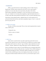
1. Introduction
RFID is a powerful and relatively simple technology. Short for “Radio Frequency
Identification”, RFID has a place in almost any walk of life. It can be used to improve
productivity at work, safety and security in government, and quality of life at home.
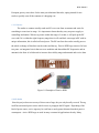
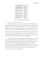
Radio Frequency Identification Transponders or “tags” have been used in various forms for
many years. Airplanes have been using radio transponders to signal and identify themselves to
air traffic control radar on the ground since World War II. They are useful for identifying our pet
dogs and cats, charge gasoline purchases, embedded chips in our vehicles ignition keys to
prevent theft, library book checkout, and SunPass transponders (figures 1.0 and 1.1) used at toll
plazas for paying road fees.
1.1 RFID System Outline
The basics of RFID are pretty simple. There are three actual components that are required
to have a RFID system:
- Transponder or tag
- Reader or scanner or Antenna
- Controller
1.1.1 RFID Tags
On the surface it would seem like a tag sends a signal to the reader which is in turn
registered by the controller, however this is not always the case. RFID devices can detect simple
radio frequency (RF) transceivers, known as “tags”, which have unique information associated
with them. Anywhere within their scan range, RFID readers can detect, differentiate, and log
dozens even hundreds of tags in a matter of seconds. RFID tags are no commonly found at many
large businesses where inventory tracking and safety is important. UPS uses RFID technology to
track packages throughout the country, automatically updating a database that is accessible to
clients! Car Max uses RFID tags not only to track employees, but also their car locations, test
driving stats, and which salesman took the most test drives [1]. In more direct impact, several
RFID- Zabala 5
European grocery stores have for the most part eliminated barcodes, opting instead for one
reader to quickly scan all the contents of a shopping cart.
1.1.1.1 Passive
The reader or scanner actually sends out RF waves out from an antenna and waits for
something to come into its range. It is important to know that they carry no power supply or
controlling mechanism. When a tag comes within the range of a reader, it will pick up the RF
wave and if it is within the right frequency range then it will send back a message in RF with its
unique information, this is called reflected power. The RF sent from the reader actually powers
the whole exchange of data between the reader and the tag. Passive RFID tags consist of at least
two parts : an integrated circuit that serves to modulate and demodulate RF frequencies and an
antenna in the form of coiled metal to increase data validity range and transmit and receive data.
Figure 1.0 Examples of Passive RFID
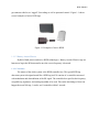
1.1.1.2 Active
Since the project does not use any of these sorts of tags, they are only broadly covered. The tag
itself has an internal power source which it uses to propagate the RF signal. Depending of the
kind of power source, active tags may be read from a much greater distance than their passive
counterparts. Active RFID tags are used in many commercial applications already. Many
RFID- Zabala 6
government vehicles are “tagged” for tracking as well as personnel control. Figure 1.1 shows
several examples of active RFID tags.
Figure 1.1 Examples of Active RFID
1.1.1.3 Battery Assisted Passive
Hybrid of both passive and active RFID technologies. Battery Assisted Passive tags use
batteries to begin the RF data transfer once the correct frequency is detected.
1.1.2 Controllers
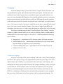
The master of the whole system is the RFID controller box. The typical RFID tag
detection system is designed much like a RFID tag itself. It consists of a controller concerned
with modulation and demodulation of the RF signal. The controller box specifies the frequency,
acceptable tag signatures, and sorting algorithm to be used. This entire interchange of data can
happen between 300 tags, 1 reader, and 1 controller within 5 seconds.
RFID- Zabala 7
Figure 1.2 SAMSys RFID Controller
Figure 1.3 SAMSys Connection Interface
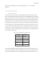
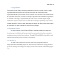
The SAMsys MP9320 v2.8e that is being used for this system is equipped with a serial port, a
digital I/O port, and Ethernet port as seen in figure 1.3. These ports enable the controller box to
be connected to a network several ways. Figure 1.4 show a possible connection schematic. This
this example, the computer controller hosting the software would also need to be connected to
the hub or server. Each controller box has its own IP address which is used by the software for
differentiation and tag tracking.
RFID- Zabala 8
Figure 1.4 Controller Network [2]
The controller connects to the antennas through the ‘Active Antennas’ connections on the front
of the box in figure (below). At least one antenna must be connected for any kind of RF signal
to be sent or received. These connections are constantly being monitored by the controller and
require special caps to be in place of the wires when an antenna is not connected. These caps will
make the controller believe that there is an antenna present but is not receiving signal, thereby
allowing the system to be functional. The controller’s ultimate purpose is to identify and
differentiate tags using different algorithms or scan settings. These indentified tags can be used
for any number of purposes, however, the controller itself cannot differentiate between signals
received from different antennas. For example, if a tag named ‘tag 1’ was presented to both
antennas in figure 1.5, the controller would simply log it twice, not as two separate scans from
different antennas.
RFID- Zabala 9
Figure 1.5 SAMSys Tag recognition
This means that if a system requires two separate registries to be made with tags (entrance and
exit through different doors), then multiple controllers and multiple antennas will be required.
Important Notes: it is important to have the antenna caps in place when a cable is not attached
or the system will not work. It is also important to mention that it is possible to set the
controller’s configuration to multiple antennas when there is only 1 antenna plugged in as long
as the caps are in place [3].
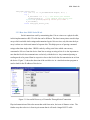
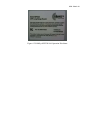
1.1.2.1 SAMSys Software
The SAMSys Software provided with the MP3920 v2.8e system allows for control of all of the
Controller box’s features. Moreover, it allows the user to “halt” tags (render them unreadable for
a chosen period of time), “kill” tags (stop reading), recognize new tags, and even create new
information for tags. The software also allows the reader to be configured, changing its name or
IP address as necessary.
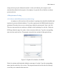
The software is most useful for initial hardware set up, since it may be used to choose the
number of operational antennas and sending commands for operation the controller. However,
the most common use of the SAMSys software is simple tag reading, differentiation, and time
stamping. Figure 1.6 illustrates these functions.
RFID- Zabala 10
Figure 1.6 SAMSys Screenshot [3].
1.1.3 Readers/Antennas
In order for a tag to be picked up, the controller has to emit an RF signal through one of its
antennas. The RF sent from the reader actually powers the whole exchange of data between the
reader and the tag. However the reader does not know if it should be looking for a specific kind
of tag or for that matter how far it could be, the reader only emits and receives the RF signal.
RFID- Zabala 11
Figure 1.7 SAMSys Reader Antenna with tag
Figure 1.8 Antenna end of reader
Each antenna is connected directly into the controller through a coaxial cable.
The total gain, or total intensity of an antenna in a certain direction, of the transmission system is
the gain of the antenna minus the loss of the cabling. For example, if the antenna has 4 dB of
gain and the coax cable has 2 db of loss over its length, the total gain is 2 dB. This characteristic
of the antenna cable limits the distance that the controller can be from the antennas.
1.3 Where the Last Project Left Off
RFID has been an ongoing data acquisition (DAQ) project at FGCU since early 2008 [4]. As far
a programming goes, a relatively complex RFID java server/client application has already been
written, but it lacks a developed internet implementation and for that matter, a network
structure[3]. Moreover, half of the code is missing rendering the project in its current state
unusable. This means that this project will need to use minimal carry over from the previous
project. However, in the last project report several options for improved work productivity were
discussed, one of which is discussed in the next section.
RFID- Zabala 12
2. Problem Description
2.1 Problem and Primary Objective
A particular experiment was explained in “Applied RFID Technology” where employees would
have RFID tags on their cellular phones which could be used for employee tracking, productivity
monitoring, and sensitive information security [3]. The report proposes placing readers at
strategically important locations and monitoring them from a master computer. This system
could be used to offer access to areas through the cell phone and allow the company to have
increased security of sensitive material. Even if a subject is able to make it through the security
door by walking in with someone authorized, it would be possible to detect their presence and
realize that they do not have access by constantly pinging for tags. Thus if the number of
authorized tags identified is less than the number of people detected, than security would be
alerted. This leads the inspiration of the proposed project. On July 23, 2009, a six car metro train
on Washington DC’s redline slammed into a stationary train resulting in nine deaths and up to
100 injuries. This accident occurred because there was no systematic verification of trains
between stations and the only trafficking system consists of signals and rail changes.
The primary objective of this project is to ensure safe train traffic through RFID tag/reader
implementation. This project will concentrate on the hardware configuration necessary to make
this system possible and the software that will monitor the tags.
Hardware requirements:
1. Reader shall “pick up” different tags
2. Reader shall send tag information to controller
3. Controller shall use multiple readers
4. Controller shall network with computer controller
5. Computer controller shall host software and controller settings
Software requirements :
1. Software shall differentiate many kinds of tags
2. Software shall connect to controller independently
3. Software shall store date/time that tags were scanned
RFID- Zabala 13
4. Software shall notify user of unsafe state
5. Software shall be Real Time safety critical system safe
2.2 Hardware Problem
As previously described, the SAMSYS MP9320 2.8e, or controller, is capable of being accessed by
RS-232 serial, RS-485, and Ethernet connections[2]. While the RS-232 appears to be working
correctly, any attempts to connect to the controller using its Ethernet port have not been
successful[5].
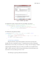
2.2.1 Set up
The controller’s user’s manual calls for all connections to be established prior to starting the
SAMSys software. Once this has been done, the software should automatically detect the
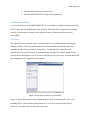
controller in either Serial or Ethernet connectivity. Continuing, if the controller is not
automatically detected, then it may be manually detected using an executable included in the
software disk called digidscvr.exe. This tool is titled Digi Device Discovery Tool and should find
any compatible device connected to the network.
Figure 2.0 Digi Device Discovery Screenshot
Figure 2.0 shows that no devices were found on the network. Several networks were set up
including WAN, LAN and direct connection as well as several versions of Digi Device
Discovery were utilized but all reach the same result.
RFID- Zabala 14
2.2.2 Troubleshooting
All attempts to contact SAMSys were unsuccessful since at the time of this report the company
no longer exists. The only troubleshooting information specific to the MP9320 2.8e available at
this time is a diagram from the user’s manual (figure 2.1)[2].
Figure 2.1 SAMSys Controller Troubleshooter[2]
“The MP9320 is equipped with an optional TCP/IP Ethernet port and embedded IP
device server. This reader is configured for automatic IP address allocation using the
Dynamic Host Configuration Protocol (DHCP) Mode and the reader automatically
extracts the IP address from the DHCP server. This is the default mode for the reader
as it is shipped from the factory”[2] .
As stated above, the controller should automatically ask for an IP address allocation using
DHCP. Since it is apparent that there is no IP address, more information on how this process
works is needed.
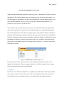
Dynamic Host Configuration Protocol (DHCP), allows a TCP/IP client to automatically request
and receive an IP address from the issuing server. When a device connects to a network, a flood
of traffic is generated to see the available hosts, as well as available servers and services.
Typically, a device will only respond if there is a request directly to that device, or if a broadcast
call packet is sent over the network. This ‘broadcasting’ requests that every device that receives
it should respond to the device that sent the packet. Knowing this, it is possible to use a
broadcast packet to track every device on the LAN “By placing network card in ‘promiscuous’
mode, along with a packet capture driver, it is possible to capture all network traffic passing by
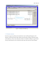
that network card host”[5]. From here, software called WireShark may be used to monitor results
and see exactly what devices are connected and under what protocol (figure 2.2). This process
consists of receiving and filtering all results that come into the network card by a process of
elimination.
RFID- Zabala 15
Figure 2.2 WireShark monitoring network traffic
2.3 Software Problem
The software requirements as outlined in section 2.1 must be satisfied by the software in
three phases:
1. Establishing communication
2. Control System
3. Data Storage
2.3.1 Establishing Communication
Software shall connect to controller independently. The software must be able to understand the
reader and successfully receive data. In order to establish communication, the right protocol
must be used by the software and the controller’s settings must be properly used.
2.3.2 Control System
Software shall notify user of unsafe state. When the software scans a tag that puts the system
into an unsafe state, it should alert the user that there is a problem. This can be done through a
constant check for unsafe state as a condition for an unsafe state protocol. Moreover, the user
should be able to search for users that are registered in the system and see their pertinent
information (last scan, how many scans).
2.3.3 Data Storage
Software shall store date/time that tags were scanned. A storage system for data retrieval must
also be implemented to enables information searching. However, most importantly, data storage
RFID- Zabala 16
ensures a safe state between software rebooting (since the actual data is not stored in the
software) and with long intervals between scans.
The rests of the software implementation depends in how to network from multiple controller
boxes to a single master computer, hosting the stored information and user. Lastly, the software
language chosen for this safety system must be certified real time system safe. Software
concerned with real time systems are those that “…operate under strict timing requirements and
may cause significant damage or loss of life, if not operating properly”[6].
RFID- Zabala 17
3. Solution
If in the Washington Metro system there had been a constant validity verification or an
automated safe state system, rather than the dated traffic signal system, then this fatal crash
could have been avoided. I propose that it is possible to improve safety and traffic flow in a
metro rail system through an RFID database with crosschecking and a master/slave relationship.
In this proposed solution, each individual train would carry RFID tags and internal controllers.
As the trains passed in and out of tunnels or high traffic areas, readers pick up on which trains is
where. If for whatever reason a train enters a tunnel but does not leave it, all traffic to the tunnel
stops via the train’s internal controller. Similarly, if the trains are mapped using RFID with
checkpoints, it becomes easy to see where major chokepoints are and how they can be alleviated.
The software solution proposed is titled “Java RFID Serial Safety Software” hereafter
referred to as JRSSS is based on the layers set out by the SAMSys software available with the
SAMSys MP9320 v2.8e as seen in figure x.x in section 3.2. JRSSS implements the following
layers as classes :
1. Mapping Layer - implemented as GUI class that controls all I/O and commands.
2. Data Management Layer – implemented as the Databasewriter class which controls
tags and manages tag properties as well as data storage
3. Connection Management Layer – implemented as Serial class that manages all
computer to device traffic.
3.1 Software Language
The choice to go with Java for software language comes after a study of which languages
are effective for a real time safety system implementation. While this project only covers a basic
implementation, the availability for a continuation lends to choosing a “safe” language. Java
currently has a real time specification RTSJ and is also currently developing a safety critical Java
system called SCJ which would deal with several safety issues inherent in java like garbage
collection and multithreading (Kornecki & Zalewski, 2009). Real time specification for Java
(RTSJ) is a combination of technologies that currently allows programmers to write programs
that meet many of the demands of real time systems in the Java programming language. The
RFID- Zabala 18
existence of this technology makes Java a suitable language over C/C++ for this safety
application.
3.2 Establishing Communication
3.2.1 Serial vs Ethernet
Due to the present hardware problems not permitting Ethernet communication from another
device, serial communication is the next logical step. This serial implementation is based on the
Simple Serial Interface (SSI) which is a free developer tool available online. Simple serial means
that the program sends/receives bytes and controls the state of serial communication signals in
the simplest way possible. As simplicity is the main goal in this class, the assumption must also
be made that there is no hardware or software flow control and that communication signals can
freely be controlled. Flow control suggests that there is a stop or pause in transmission , either
write or read from either computer or device, to allow the full transmission to be sent. This may
mean that due to excessive commands, tag reads, or ‘noise’ the device stack may overflow and
cause a failure. Due to the level of implementation which this project is accomplishing, this risk
is not addressed in this document.
Table 3.0 Serial Settings In Use: MP9320 v2.8e
RF Scanning
Continuous
Serial Reporting
Continuous
Baud Rate
57600
Data Bits
8
Stop Bits
1
Parity
None
Flow Control
None
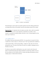
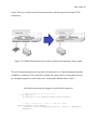
The Serial class that handles connections completely replaces the TCP/IP class and Discovery
class, rather than supplements, which is found in figure 3.0. The Connection Management Layer
functions in the SAMSys software by communicating with the physical transport layer of the
RFID- Zabala 19
reader. This layer is based on the IConnection interface ideally supports Serial and TCP/IP
connectivity.
Figure 3.0 SAMSys Management Layers (left) to Software Development Classes (right)
The serial connection detects the com port to which the device is connected and automatically
establishes a connection. This connection is held by the system until it is released by the user (
by closing the program) or until it times out ( from possible hardware/device fault ).
Java Serial connection code snippet for typical serial connection:
// New instance of the serial port.
if (m_IsNative) {
m_SerialPort = new SimpleSerialNative(m_PortIndex);
}
// New a serial port. Pass in comm port number
SimpleSerialNative(int comPort) {
_initPort( convertToCommString(comPort), 57600, 8, ONESTOPBIT,
NOPARITY);
}
RFID- Zabala 20
find_open_serial_port:
for (ii = 0; ii < m_PortMenuItem.length; ii++) {
try {
m_PortIndex = ii + 1; // the serial port wanted
initSerialPort(); // Try opening this serial port.
System.out.println("Opening serial port Comm" +
m_PortIndex);
break find_open_serial_port;
3.2.2 How does JRSSS Serial Work
Serial connections work by transmitting data 1 bit at a time over a physical cable,
in this implementation a RS-232 cable but can be different. The data is many times stored in byte
arrays which can hold whole strings and transmitted again 1 bit at a time, only this time the byte
array is taken as a whole unit instead of separate bits. This helps process of passing command
strings rather than single chars. JRSSS works by calling serial class which converts any
command or I/O to or from the device from bits to strings or string to bits. It is also important to
note that the Serial class communicates exclusively with the device. Any command passing or
reading needs to be passed from its respective class to the Serial class for transmission to or from
the device. Figure 3.1 shows the detection of the serial device in a similar detection program as
used to look for the IP address of the device.
Figure 3.1 Successful Discovery of Controller Through Serial Connection
Physical transmission of bits also means that aside from noise, the issue of distance exists. The
further away that a device is from its pair means that it will need a longer RS-232 cable.
RFID- Zabala 21
Unfortunately, serial communications are greatly limited by this distance and quickly lose
discernable data. It is possible to amplify the range of discernable serial communication, but it
requires an amplification which again, only extends the length of the cable but does not solve the
problem[2].
3.3 Control System
The user is must be notified of any unsafe state. But this may change from application to
application because an unsafe state in one may be acceptable in another. For example, in a social
networking website, it may be acceptable to have some data loss to maintain the speed of
database access and since old data is rarely retrieved, a marginal loss is acceptable. In contrast,
hospital records stored in a database must not be lost and extra care must be taken to maintain a
lossless state. In this way, an unsafe state alarm must reflect the application that it is serving.
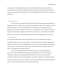
3.3.1 Application
In the proposed train traffic example, the application would be a notification that there is a
potentially unsafe state in some tunnel, track, or intersection. This alert could be generated by a
constant cross check of tag scans and database records. As a train passes through an intersection,
enters a track, or enters a tunnel, its tag would be scanned and a time stamp would be issued.
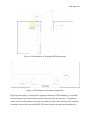
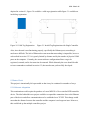
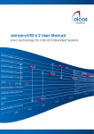
Figure 3.2 illustrates the example as follows:
The 23 train heading north bound from point X to point Y must pass through an
intersection where an eastbound train joins the north redline track. If a the 23 train passes
checkpoint A and has its tags scanned/registered but has not yet been scanned by the B
checkpoint antenna, then a train leaving station C eastbound would have an unsafe state and be
forced to stop operation. Moreover, if the 23 train takes longer than usual to reach checkpoint B
or never reaches it at all, then train 23 will be in an unsafe state.
RFID- Zabala 22
Figure 3.2 Unsafe State Train Example
3.3.2 GUI
The GUI acts as a user notification system where if there is an unsafe state, the user is alerted by
the software. Final implementation should include individual controllers within trains to be
alerted of the unsafe state and discontinue operation until the flag is reset or an administrator
overrides the unsafe state.
3.4 Data Storage
In order to maintain safety and program independence, the data is stored outside of the software,
meaning that a software fail state does not mean data corruption. The data storage occurs in a
database which networks to the actual java program.
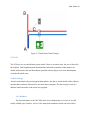
3.4.1 Database
The chosen database is the 2007 Microsoft Access database due to its ease of use and
readily editable query features. Access is like many basic databases in that it involves tables,
RFID- Zabala 23
forms, and queries, but unlike other more complex database platforms it does not require
complex permissions.
Figure 3.3 Access Data Base holding RFID Information
3.4.2 JDBC Connection
To connect to any external database from a Java program, a Java DataBase
Connection (JDBC) needs to be made. To establish a connection two steps are necessary :
1. Import the database driver
2. Create a JDBC connection
While for many systems it may be necessary to download a separate database driver (ex. SQL
2008 or Oracle 11g), for the Access to Java connection in this project it is unnecessary. Rather, I
use the ODBC service available through Windows and the SQL drivers already available in Java.
The java api reserved for database operations can be accessed by importing the following line:
“import java.sql.*;” and will allow the programmer to access classes such as Connection,
Statement, and ResultSet [7].
The ODBC Data Source Administrator in figure 3.4 can be accessed in the administrative tools
menu of most Windows operating systems.
RFID- Zabala 24
Figure 3.4 ODBC setup window
Java Method for creating a connection from Java to the ODBC created above:
// Method to make the connection to database and perform its setup
void OpenConnection () throws SQLException {
// Make the connection to ODBC title rfidsource
conn = DriverManager.getConnection("jdbc:odbc:rfidsource");
Statement s = conn.createStatement()
}
Java Method for writing data into database
void WriteData(String tag, String time, String Reader) throws
SQLException{
Statement s = conn.createStatement();
String state = "INSERT INTO tags VALUES('" + tag + "', '" + time + "',
'" + Reader + "')";
int temp = s.executeUpdate(state);
}
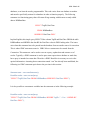
3.4.3 Data Types and Delimiters
Half of the data that is inserted into the database comes from the serial class after
decoding. This class, as explained in section 3.2.2 transmits and receives bits of information.
When the bits are received, they are converted to text or “Strings” in the Java language. This data
is then passed into the database. However, in order to successfully receive any data from an
ODBC or JDBC connection, the field’s data type and the data type of the data being received
must match. In Access, the data type for text is “Text”.
The following is a typical tag information transmission:
RFID- Zabala 25
{Rd,d:E016000000000D53,t:IS186A;C4
What makes this information significant is that every piece of information is a mixture of letters
and numbers. The actual tag identification is found between the first and second commas. It is
easy to see that it is impossible to use any of this information as a typical integer primary key as
used in normal databases. However, since every tag has a different unique identifier, it is
possible to use this value as its indexed name.
The receipt of a tag is usually followed by its time stamp. This data follows the tag identifier
above and is separated by a semicolon. It is possible to delimiter or separate this information
based on this punctuation. After the java program sends a string with the complete information
(identifier and timestamp) the database automatically separates the information into TagID and
DateTime. Other information passed to the database include the tagName and ReaderNo which is
the signature of whichever controller registered the tag event. It stands to reason that all data
types in the Access database must be of Text type such as in figure 3.5 in order to receive and
send data successfully.
Figure 3.5 RfidDataBase Table Design View
Lastly, the noise from the serial connection creates substantial “garbage” data that is also
inputted into the database. The java program can take care of this by using the most common
form of a tag and use that as the accepted TagID.
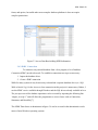
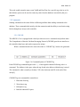
3.4.4 Queries
In order to receive data from a database it is possible to query the data or selectively search the
data. Queries are pieces of code that can be used to return data that fits certain criteria from
selected tables, rows, and columns. Queries are executed within the database and make
RFID- Zabala 26
databases, or at least the results, programmable. This code varies from one database to another
and must be specifically written for a database in order to function properly. The following
statement is a functioning query that will return all tags starting with the most recently added
data to RfidDataBase.
SELECT TagID, DateTime
FROM RfidDataBase
ORDER BY DateTime DESC
In plain English, this simple query SELECTS the column TagID and DateTime FROM the table
RfidDataBase and ORDERs the data BY the DateTime value in DESCending order. The issues
arise when this statement has to be passed into the database from an outside source for execution.
This is where JDBC statements come in. JDBC allows a statement to be created from the
Connection. This statement can be used to execute a query, update data and return a set of
results. Typically, a JDBC statement is used to pass some request into a database or send data,
but a query is intended to return data. Therefore a JDBC ResultSet is necessary to receive the
queried information. Assuming that a connection named “con” has already been established, the
following is a JDBC statement equivalent to the previous in this section:
Statement stmt = con.createStatement();
ResultSet results = stmt.executeQuery(
"SELECT TagID, DateTime FROM RfidDataBase ORDER BY DateTime DESC");
It is also possible to concatenate variables into the statement as in the following example:
ResultSet results = stmt.executeQuery(
"SELECT TagID, DateTime FROM RfidDataBase WHERE TagID =” + Var + “ORDER BY
DateTime DESC");
RFID- Zabala 27
This code would return the most recent TagID and DateTime for a specific tag value in var. In
this fashion, queries can be used to return any value from the database as needed by the java
program.
3.5 Commands
Sending commands to the reader follows different guidelines than sending commands to the
database. These commands deal entirely with the connection and the ability to send entire string
blocks through byte arrays to the controller.
3.5.1 CHUMP
The MP9320 v2.8e is equipped with a data layer that can receive commands and perform tasks.
The Comprehensive Heuristic Uniform Messaging Protocol (CHUMP) provides an interface to
the controllers data layer and can be expressed as strings.
When a command needs to be sent to the reader a “CHUMP Tag” needs to be generated.
Figure 3.6 Command Syntax of CHUMP Tag
Each CHUMP tag command begins with a ‘ } ‘ which signifies that the following code is a
command. The Address is the space where the tag id and write address within the tag is stored.
The command is what is actually to be done. XX is the checksum and CR is the end of line
check[2].
CHUMP Tags can command the controller to:
1. Read data from tag
2. Write data to tag
3. Halt/Quiet a tag
4. Read the onboard I/O ports
RFID- Zabala 28
With this information it is easy to see how one could send a message to the controller that names
a tag. The following code line uses the write function of CHUMP to write the string “BOB” into
the tag with the id of “E00300001122334455667788”:
}d:E00300001122334455667788,wt b:BOB,a:20,CR!
RFID- Zabala 29
4. Experiments
The properly test the validity of the project and ensure its success as a safety system, a proper
experiment should be designed. This experiment must take into account the software
requirements and one by one test their success or failure. Also, since this is a test of the software,
the experiment must ensure, or assume if ensuring is impossible, that the hardware requirements
are satisfied. At this stage in implementation, the software is by no means fully developed.
Furthermore, only one controller unit is available for use barring the possibility of any location
oriented experiment. Therefore, rather than testing the complex and safety-critical train example,
the experiment will focus on another less critical real life example.
4.1 Experiment Scenario
In a large warehouse, it has become difficult to control the timesheets of employees.
Several entrances, odd shifts, and lost punch cards have prevented workers from consistently
providing accurate records of their work hours. Through RFID and JRSSS it is possible to track
employee hours and prevent loss of wages or overpayment.
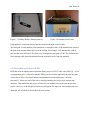
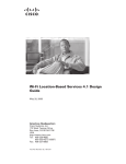
4.1.1 The Set Up
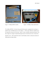
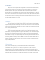
The front of the warehouse has a narrow entranceway through which much of
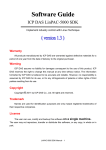
management enters the building (figure 4.0). The back of the warehouse has a large gate that is
open in the mornings and evenings to let employees and trucks in and out of the building (figure
4.1).
RFID- Zabala 30
Figure 4.0 Front Entrance of Warehouse RFID Experiment
Figure 4.1 Rear Entrance of Warehouse Experiment
By giving each employee a badge that is equipped with passive RFID technology, it is possible
to track employees log in and out hours down to the second for any given day. As employees
walk in and out of the entrances, their tags are picked up by the readers and sent to the controller
which then conveys the data to the JRSSS. The software passes this data into the database for
RFID- Zabala 31
storage and can query the information needed. At the end of the day, the computer could
automatically subtract the last register of an employee’s tag by the first to find the exact hours
present at the site.
4.2 Requirements Testing
4.2.1 Software shall differentiate many kinds of tags
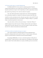
As employees walk in and out of the warehouse’s openings, they should be identified and
registered as present within the database. To test this requirement, the JRSSS should already be
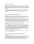
operational. Presently, there are two activated tags within the system named ‘Jaime’ and ‘Jim’.
These two tags represent two employees walking in at the beginning of a work day. Bring one
RFID tag within the range of a reader ( it does not matter which one). Type the corresponding
name into the search text box. The program returns the last scan date for that particular tag.
Figure 4.3 Graphical User Interface for JRSSS
Wait a few minutes and bring both within the scan range of a reader. Type the corresponding
names into the search box, one at a time. The program returns the last scan date for both tags,
even if they were scanned at the same time.
RFID- Zabala 32
4.2.2 Software shall connect to controller independently
The JRSSS and MP9320 v2.8e are meant to be constantly operational. Therefore,
connection and disconnection is not a common aspect of operation. However, it is obviously an
important step that must occur prior to the first tags being successfully registered by the software
(but controller may pick them up if it is on but not connected to computer).
First, ensure that all connections are properly made. Power cord must be plugged into
120V outlet and into controller box. Antenna to be used must be connected to the front of the
controller box and any unused ports must have the proper caps in place. Lastly, the RS-232 serial
cable must be connected from the device to the computer’s COM port (COM port 1 is preferable
if there is more than one port but it is not necessary).
Start up the software and observe the System messages. “Connected to COM port 1”
should be displayed if successful. If not, then “COM port cannot be found” may be displayed.
Another check to ensure the connection’s success is to scan a tag and see if there is any activity
in the GUI. If so, then the connection has successfully been made.
4.2.3 Software shall store date/time that tags were scanned
Once a tag has already been scanned and registered, the tag’s information may be
requested by entering its name into the search box. However, if a specific instance of the tag is
required or a specific date/time is needed, then it must be found in the database.
By opening the RfidDataBase, it is easy to see that each tag instance is followed by its
scan date and time. To make sure this is accurate, simply scan a tag, making note of the tag name
and time scanned. Then check the database or use a query to find the tag’s most recent scan date.
RFID- Zabala 33
Figure 4.4 Date and Time Stored in Database
4.2.4 Software shall notify user of unsafe state
This requirement takes on two roles. First, it means that if for some reason the software
does not believe that operation is safe or possible, it should return an error or a message to stop
operation. Since this is not a safety critical experiment, this safe state is not applicable. However,
the equivalent for an unsafe state for this system would be if a new unrecognized tag were
introduced or if an employee’s tag information had not yet been entered when it was requested.
The latter circumstance may be tested by entering a made up name into the search box. In this
instance, since there are only 2 programmed name, it can be any string other than ‘Jaime’ or
‘Jim’. It’s noteworthy to say that these names are not case sensitive. An error message alerting
the user that this person does not exist within the system will be displayed.
The second role that unsafe means for this application has to do with the waves emitted
by the antennas. While not yet implemented, the final version of this safety software must alert
users when there is a potential danger posed by the RF waves coming from the antennas. An
employee with a pace maker or highly sensitive hearing aids may have his or her device
damaged by strong RF waves. While the SAMSys disclaimer on the actual controller box in
figure 4.5 claims to not have harmful effects, there have been cases of accidental injury related to
RF signals. The controller box has varying signal frequency and wavelengths and may be
changed fit the physical needs of certain employees.
RFID- Zabala 34
Figure 4.5 SAMSys MP9320 Safe Operation Disclaimer
RFID- Zabala 35
5. Conclusion
This project is an investigation into an important area of software development. Safetycritical real time systems exist in most aspects of life; from the airport, to cars, and even in
hospital equipment. These systems’ functionality and safe operation depends on smooth
operation and correct event handling, which comes directly from the programmer. It is the goal
of any safety- critical real time system program to accurately, safely, and compactly encapsulate
all aspects and scenarios of a situation in the software and properly handle them in such a way as
to avoid damage to property or loss of life.
5.1 Summary
The Java Realtime Serial Safety Software (JRSSS) is the first step toward developing a
complex and integrated safety monitoring system for a metro rail system. The steps and ground
work set out by this document is intended to be a start to a larger, more broad project that could
cover various professions/majors.
RFID is a growing technology that is trusted by some of the largest companies in the
United States. The growth in popularity is not due to the technology’ cost, which remains high,
but because of the technology’s potential. RFID is capable of accurately tracking high speed
trains with the use of tags, it is capable of being used to track large inventories down to the last
item. During WWII, a technology similar to RFID was used to safely identify fighter planes at
runways. With steps in the right direction, it can also be used to ensure safe operation in more
aspects of daily human life.
5.2 Project Status
As the project stands right now, it is being limited by the hardware implementation.
Unfortunately, only one MP9320 v2.8e controller is available for use and is actual not
functioning correctly. This eliminates the possibility of locational safety testing because the
controller cannot differentiate between antennas when a tag is scanned. This means that the only
functionality that one controller has is a single state registration. For example, in the scenario
RFID- Zabala 36
depicted in section 4.1, figure 5.0 would be a valid tag registration while figure 5.1 would be an
invalid tag registration.
Figure 5.0 Valid Tag Registration
Figure 5.1 Invalid Tag Registration with Single Controller
Also, since the unit is not functioning properly, specifically the Ethernet port, networking is
much more difficult. The lack of Ethernet does not mean that networking is impossible, however
as described in section 3.2.2 it is greatly limited by distance and by the number of physical COM
ports on the computer. Currently, the current software configuration allows a tag to be
registered, scanned, and its last scan time be returned. While ultimately the users should be able
to issue commands as outlined in section 3.5, that area has not yet been fully developed.
5.3Future Work
This project is intentionally left open ended so that it may be continued in a number of ways.
5.3.1 Ethernet Adaptation
This continuation would require the purchase of a new MP9320 v2.8e or similar RFID controller
device. The idea behind this new project would be to expand the connection class to the Ethernet
port of the device and allow communications to be established over TCP/IP. This change would
mean that the distance between the controller and the computer is no longer an issue. Moreover,
this would lead up the multiple controllers project.
RFID- Zabala 37
5.3.2 Multiple Controllers
This continuation assumes that either the controlling computer has multiple physical COM
ports or the Ethernet adaptation project has already been accomplished. The multiple
controllers project would allow the “invalid” operation in figure x.x (section 5.2). The tricky part
of this future project would involve linking the controllers into a single java program and
database. Ideally, the controllers would differentiate themselves with some signal which may
be used for accurate reads and writes.
RFID- Zabala 38
6. References
1. Scher, B. (2009, Jan 14). Dynasys - RFID Technologies for Business and Science. (S. T. 2008/2009,
Interviewer)
2. SAMSys Technologies, Inc. (2005, September 27). User's Guide, MP9320 v2.8e EPC UHF LongRange Reader. Richmond Hill, Ontario, Canada: SAMSys Technologies, Inc.
3. Gallegos, J. (2008). Applied RFID Technology. Fort Myers: FGCU.
4. Flechsig, E., Kovtunenko, O., Porter, & Robert. (2008). Data Acquisition Through RFID. Fort
Myers: FGCU.
5. Bennett, T. (2009). SAMSYS MP9320 report of Attempted Configuration. Fort Myers, Florida:
FGCU.
6. Kornecki, A., & Zalewski, J. (2009). Certification of software for real-time safety-critical systems:
state of the art. Innovations in Systems and Software Engineering , 149-159.
7. Bishop, J. (2001). Java Gently, 3rd ed. Addison-Wesley Pub Co