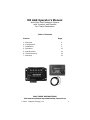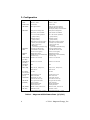
1
ME AGS Auto Gen Start Network System with Inverter and Remote for Coach Generators Operators Manual ME AGS Operators Manual Auto Gen Start Network System with Inverter and Remote for Coach Generators Table of Contents Section 1. 2. 3. 4. 5. 6. 7. Overview Configuration Installation Operation Specifications Troubleshooting Warranty Page 2 3 5 12 14 15 16 SAVE THESE INSTRUCTIONS This manual contains important safety instructions. 2004 - Magnum Energy, Inc. 1 1. Overview IMPORTANT SAFETY INFORMATION This product must be installed by a qualified technician in accordance with all applicable electrical codes Always disconnect the coachs batteries before installing this product Remove the generators spark plug (or disconnect the battery on diesel generators) to prevent accidental starting during installation of this product Use insulated tools The Auto Gen Start System for Coach Generators Congratulations on purchasing your new Auto Gen Start (AGS) Network System with Inverter and Remote for coach generators. The AGS is designed to automatically start your coach generator, based on the inside temperature of the coach or a low battery condition. These features allow you to leave pets and precious items in your coach while you enjoy a day away golfing, touring or just sight seeing - all the while knowing your coach will stay cool and comfortable. Even if you dont have pets, theres nothing better than returning a nice cool coach while dry camping in hot weather. Plus, you will always have charged batteries - no more worrying about dead batteries. The AGS also includes settings for "Quiet Time" so you can comply with park and rally rules. The AGS does not interfere with your air conditioner controls or the manual generator start/stop switches in your coach. Installing the AGS is a simple process and requires the following tools: Pencil Electrical Tape Level Drill Phillips Screw Driver 7/64 & 1/8 Drill Bits Utility Knife or Hole Saw 2 2004 - Magnum Energy, Inc. 2. Configuration 1. Configuring the AGS Controller The Magnum AGS Controller can be configured for 12 or 24 VDC operation. It can also be configured for various diesel or gas generator brands and models. The controllers default settings are set for "12 VDC" and "Diesel" operation. If necessary, refer to Table 1 (next page) to determine which setting is correct for your system. To access the jumpers, remove the controllers four cover screws. For Onan Quiet Diesel generators, the controller is configured with the "Diesel/Gas" jumper positioned over the two left-hand pins as shown below (factory default). For most "gas" as well as other diesel generators you must configure the controller with the "Diesel/Gas" jumper positioned over the two right-hand pins as shown below For 12 Volt DC operation, the controller is configured with the "12/24 V" jumper positioned over the two left-hand pins as shown below (factory default). For 24 Volt DC operation, you must configure the controller with the "12/24 V" jumper positioned over the two right-hand pins as shown below. Remove the four cover screws 12/24 V Jumper Onan Quiet Diesel (default) Other Diesel and Gas Not Used Controller and Internal Board DIESEL/GAS Jumper 12 VDC Operation (default) 24 VDC Operation Figure 1 - AGS Controller Configuration (DIESEL/GAS and 12/24 V DC Operation) 2004 - Magnum Energy, Inc. 3 2. Configuration VERSION V 2.0 V 2.1 DATE March 1, 2004 March 1, 2004 START TYPE 3-wire start 3-wire start GEN TYPES Onan Quiet Diesel Most gas and other diesels: Emerald, Marquis, MicroLite, MicroQuiet, Onan, and PowerTech FEATURES Temp & low voltage start Temp & low voltage start Quiet time, & net enabled Quiet time & net enabled 12 or 24 volt DC operation (jumper select) 12 or 24 volt DC operation (jumper select) Software version (jumper select) Software version (jumper select) Temp start (connects 3 ways) Directly to a/c thermostat Uses a sensor only Wall switch (stand alone operation only) Temp start (connects 3 ways) Directly to a/c thermostat Uses a sensor only Wall switch (stand alone operation only) NETWORK PORT Connects to ME inverter (uses ME-RC remote with version 0.5 or higher) Connects to ME inverter (uses ME-RC remote with version 0.5 or higher) REMOTE PORT Stand alone switch, pigtail direct to a/c thermostat, or sensor only Stand alone switch, pigtail direct to a/c thermostat, or sensor only START RELAY (pin 5&6) closes for 20 seconds closes for 10 seconds STOP RELAY (pin 6&7) closes for 10 seconds closes for 10 seconds AUX RELAY (pin 1&8) N/A N/A RELAY SEQ Stop 10 sec, Delay 4 sec, Start 20 sec Stop 10 sec, Delay 4 sec, Start 10 sec B+ Voltage (min at pin 2) 10 VDC 10 VDC B+ GEN RUN (pin 2) checks for B+ 2 sec after crank time checks for B+ 2 sec after crank time TEST MODE Ignores B+ for test (runs 30 sec then off) Ignores B+ for test (runs 30 sec then off) GEN START (MANUAL) Yes, ignores auto start (if B+ present) Allows manual start within quiet time Yes, ignores auto start (if B+ present) Allows manual start within quiet time LED, GREEN Blinks on start, solid on run Blinks on start, solid on run LED, RED Red after 4 tries (Time between tries = 2 min) Red after 4 tries (Time between tries = 2 min) Table 1 - Magnum AGS Software Revs (4/2/04) 4 2004 - Magnum Energy, Inc. 3. Installation Installing the AGS Controller In most cases, the Auto Gen Start (AGS) Network System with Inverter and Remote has been installed by the coach manufacturer. 1. Determine a suitable location to mount the Auto Gen Start (AGS) Controller. It must be located in a clean, dry and protected place. The controller can be mounted in any direction; however, allow ample room to access the adjustment dials and to view the LEDs for troubleshooting. Wiring is much easier if the controller is mounted within easy access to the generators remote wiring. Pre-drill the four 1/8 holes if necessary. 2. Remove the 8 pin connector from the controller by pulling it straight out. Wire the controller according to Figures 3 and 4 (see pages 8 and 9). 3. Use the four 8x3/4 screws (provided) to mount the controller to the coachs wall. 4. When all of the wiring is complete, plug the 8 pin connector back into the AGS controller. 5. Connect the AGS Controllers "NETWORK" port to the inverters "NETWORK" port using the 4 wire twisted pair cable. Remote Controller Sensor Cable Figure 2 - AGS Controller, Sensor and Remote 2004 - Magnum Energy, Inc. 5 3. Installation Installing the AGS Interior Temperature Sensor WARNING: Always check for hidden wires, pipes and cables before drilling or cutting into the coachs walls and cabinets. There are three options for installing the AGS Interior Temperature Sensor which are all used in conjunction with the ME-RC remote control. You must specify which option you would like when ordering your Magnum AGS system or call the factory to order if your system did not come with the desired option. 1) a wall-mount switch with integrated temperature sensor; 2) a 4 wire cable with temperature sensor (OEM Installs only); 3) a direct connection to the a/c thermostat via a 2 wire pigtail assembly (OEM Installs only). AGS Wall Switch Installation (option) 1. Locate a convenient spot to mount the AGS Switch. The side wall of the coachs refrigerator enclosure is the most common (and recommended). The switch should be mounted midway up the wall for best results. NOTE: The thermistor that is used to sense the coachs interior temperature is located on the back of the AGS Switch. It is vital that the switch be placed where interior room temperatures can be accurately sensed by the thermistor. Keep the sensor away from heating and air conditioning ducts, window drafts and avoid mounting it on the coachs exterior walls. Interior walls and cabinets provide much more stable temperatures and also make it easier to route the switchs cable to the AGS Controller. 2. Use the template at the rear of the manual to cut a hole for the AGS Switch. Feed the 6 wire phone cable through the opening and route it to the AGS Controller. Use care in routing the cable to insure the cable does not become pinched or cut by rough or sharp edges. Leave enough slack to allow cable movement once the installation is complete. 3. Make sure the switch is the "OFF" position and then plug the cable into the RJ-11 phone connector on the back of the AGS Switch. Mount the switch to the wall using the two 6x1 screws provided. 6 2004 - Magnum Energy, Inc. 3. Installation 4. Plug the other end of the 6 wire phone cable into the AGS Controllers RJ-11 connector marked "Remote." 5. If all wiring is correct, the unit performs a "self test" when power is applied. The "STATUS" LED blinks green. At the same time, the "READY" LED turns on solid green. 6. Reconnect the generators spark plug (or reconnect the battery for diesel generators). 4-wire Cable w/Temperature Sensor Installation (option) 1. The sensor is normally located behind the wall thermostat (on the mounting plate) or next to the thermostat remote sensor (installed by the OEM). These are the two most common and recommended mounting locations. NOTE: The thermistor that is used to sense the coachs interior temperature is located at the very tip of the sensor cable. It is vital that the sensor be placed where interior room temperatures can be accurately monitored by the thermistor. Keep the switch away from heating and air conditioning ducts, window drafts and avoid mounting it on the coachs exterior walls. Interior walls and cabinets provide much more stable temperatures and make it easier to route the cable to the Controller. 2. Plug the other end of the 4 wire phone cable into the AGS Controllers RJ-11 connector marked "REMOTE." 3. If all wiring is correct, the system performs a "self test" when power is applied. The controllers "STATUS" LED blinks green. At the same time, the "READY" LED turns on solid green. If the remote is not connected, the controllers "READY" LED blinks green. Installation is now complete. 4. Reconnect the generators spark plug (or reconnect the battery for diesel generators). Direct Connection to A/C Thermostat (option) NOTE: OEM installation only. Contact factory for questions regarding this feature. 2004 - Magnum Energy, Inc. 7 3. Installation 4 Wire Twisted Pair Cable ME Series Inverter 4 Wire Sensor Cable AGS Controller AGS Controller AGS Sensor 1 2 3 4 5 6 7 8 Aux Aux Remote GEN Hour Meter - + Start 5 Amp Comm Ground Stop Fuse + GEN Start/Stop Switch - 12 VDC Battery Ground Figure 3 - AGS Wiring Diagram 8 2004 - Magnum Energy, Inc. 3. Installation Note: Pin #1 is located on the LEFT side facing the terminal block 1 2 4 Wire Connector to Sensor 6 Wire Connector to Inverter 3 4 5 6 7 8 Aux Contact Generator Stop / Preheat Common from Generator Start / Stop Switch (Ground) Generator Start - 12 VDC (Negative) from Battery + 12 VDC (Positive) from Battery Generator B+ (+ 12 VDC) from Generator Hour Meter Aux Contact Figure 4 - AGS Connector Pin Legend (from left to right) 2004 - Magnum Energy, Inc. 9 3. Installation The AGS comes preset for voltage, temperature and generator run time directly from the factory. Quiet Time is factory preset to "OFF" (defeated). For the majority of customers, no adjustments are necessary. If you need to make changes to the factory adjustments, you can do so by rotating the knobs on the AGS Controllers front panel (refer to next page) 1. The "START TEMP F" factory setting is set at 75 °F (25 °C). When the inside coach temperature reaches this point, the generator will automatically start to power the air conditioner. NOTE: To change this setting, slowly rotate the knob marked "START TEMP F" clockwise to increase temperature or counterclockwise to decrease temperature. The temperature range is adjustable from 65 °F to 85 °F (18 °C to 29 °C). 2. The "START VOLTS" factory setting is set at 11 VDC. When the battery voltage drops to this setting, the generator will automatically start and recharge the batteries. There is a 2 minute delay once the voltage setting is reached. NOTE: To change this setting, slowly rotate the knob marked "START VOLTS" clockwise to increase the voltage or counterclockwise to decrease voltage. The range is 10 VDC to 12 VDC. NOTE: This system is capable of both 12 VDC and 24 VDC operation. For 24 VDC applications, the value indicated on the cover is automatically doubled (i.e., 11 VDC equals 22 VDC). 3. The "RUN TIME HOURS" factory setting is set at 2 hours. This is the length of time the generator will run once the "START TEMP F" or "START VOLTS DC" setting has been reached and the generator starts. NOTE: To change this setting, slowly rotate the knob marked "RUN TIME HRS" clockwise to increase generator run time and counterclockwise to decrease generator run time. Generator run time can be set from 1 to 5 hours. NOTE: To defeat the Temperature or Voltage Start feature, turn the adjustment knob fully counter-clockwise (OFF). 4. The AGS Controller has a 24 hour internal clock. When using the inverters Network Port, the Controllers Clock dial is defeated. Set the clock with the remote control (page 12). Once set, the clock will continue to keep time. In the event of loss of power to the controller, you must reset the clock. 10 2004 - Magnum Energy, Inc. 3. Installation 5. "QUIET TIME" is a program that prevents the generator from starting during specific hours of the evening and early morning. It is adjustable for five pre-selected time ranges. To set quiet time, turn the dial either counter-clockwise or clockwise to the hours required: 9-7 (9 PM to 7 AM), 9-8 (9 PM to 8 AM), 9-9 (9 PM to 9 AM), 10-8 (10 PM to 8 AM), 11-8 (11 PM to 8 AM). The program only needs to be set once. RUN TIME HOURS Adjustment START TEMP F Adjustment START VOLTS DC Adjustment CLOCK AM/PM (Use Remote to Set Clock) QUIET TIME PM/AM Adjustment READY LED TEST Switch STATUS LED Figure 5 - AGS Controller Adjustments (Run Time Hours, Start Temp F, and Start Volts DC) LCD Display SELECT Rotary Knob Charger Standby Set Current Time AGS Menu Selection Soft Key NOTE: In the event the control module loses power, the CLOCK must be reset. Figure 6 - Remote Control and Clock Function 2004 - Magnum Energy, Inc. 11 4. Operation The AGS Remote Control is equipped with a wide range of easy-to-use switches and displays, allowing you to quickly setup your inverter/charger as well as determine its operational status. The "AGS" soft key controls the operation of the networked AGS Controller (refer to figures on page 11). Rotary SELECT Knob Similar to a dash radio knob, use the SELECT knob to move between menus and select program options. Turn the knob clockwise to increase value or counter-clockwise to the decrease value. Press the knob to "save" the selection. AGS Soft Key Press the AGS soft key to access AGS menu and then turn the rotary "SELECT" knob to view the following menu items (refer to table 2 on page 14). AutoGenSt Cntrl Used to turns the AGS (Auto Gen Start) ON and OFF or to enable "Quiet Time." AutoGenSt OFF Disables the Auto Gen Start function. AutoGenSt Enabl Enables the AGS system to automatically start the generator based on the coachs interior temperature or low battery voltage conditions. Temperature and voltage settings are selected using the AGS Controller (page 11). AutoGenSt Test Starts and runs the generator for 30 seconds, fully testing the AGS system. AGS w/Quiet Time Identical to the ENABLE setting above but sets QUIET TIME. When this selection is made, the Set Current Time (clock) menu appears, prompting you to set the current time. Set the required "QUIET TIME" hours using the AGS Controller (see pages 10 - 11). NOTE: If the generator is running when START QUIET TIME is reached, it will automatically stop and will not start again until END QUIET TIME is reached. Set Current Time When you access the Set Current Time menu, press the Select knob. This displays the "Set Hour" menu. Turn the SELECT knob clockwise to increase the hour or counter-clockwise to decrease the hour. Press the knob to save the setting and advance to the Set Minutes menu. Repeat the steps and advance to the "Set AM/PM." Press the knob to save your selection. NOTE: If the current time is correct, you can press any of the soft keys to escape without affecting the settings or the press the SELECT knob to advance through the various fields. 12 2004 - Magnum Energy, Inc. 4. Operation WARNING: Set the AGS to "AutoGenSt OFF" before servicing the electrical or generator system. NOTE: It is recommended that the AGS be set to "AutoGenSt OFF" while storing or leaving the coach unattended for extended lengths of time. This setting is also recommended whenever the coach is plugged into shore power. 1. Set the air conditioner thermostat to match the AGS "START TEMP F" setting. If two air conditioners, it is suggested that the second air conditioner thermostat be set 2° to 5° higher than the first air conditioner. This staggered setting allows the first air conditioner to keep the coach cool. The second air conditioner will only switch on if the coach temperature continues to rise, thus conserving power. 2. Set the "START VOLTS DC" to 11 VDC (or 22 VDC). 3. Activate the system by setting the AGS to "AutoGenSt Enabl." This is the normal operating setting. When the coachs inside temperature reaches the "START TEMP F" or the "START VOLTS DC" setting, the LED will blink green and the AGS will initiate the generator start sequence. The AGS will attempt 4 times to start the generator. If the generator fails to start, the LED will turn red indicating a fault. When the generator starts, it will continue to run until the "RUN TIME HRS" setting is reached at which time a stop signal is sent to the generator. To manually stop the generator anytime during the run time cycle, simply set the AGS to "AutoGenSt OFF." NOTE: Once the generator has completed the "RUN TIME HRS," the AGS will immediately monitor the "TEMP START F" and "START VOLTS DC" for the next auto start cycle. If a fault occurs, set the AGS to "AutoGenSt OFF" and then back to "AutoGenSt Enabl" to reset the system. If the problem persists, check the troubleshooting chart at the back of the manual. 2004 - Magnum Energy, Inc. 13 5. Specifications Weight (Controller) 1 lb (0.5 kg) Weight (Switch) 0.25 lb (0.1 kg) Dimensions (Controller) 3.0 H x 5.2 W x 1.33 D (7.6 cm H x 13.2 cm W x 3.3 cm D) Dimensions (Switch) 2.25 H x 3.25 W x 1.5 D (5.7 cm H x 8.3 cm W x 3.8 cm D) Electrical Requirements Controls 12 VDC or 24 VDC Enable, Off, Test LED Indicator Temp Sense Range On, Off, Fault Condition 65 °F to 85 °F (18 °C to 29 °C) Voltage Start Range 75 °F (25 °C) - factory setting 10 VDC to 12 VDC (or) Quiet Time Range 20 VDC to 24 VDC 9PM to 7AM, 9PM to 8AM, 9PM to 9AM, Clock 10PM to 8AM, 11PM to 8AM 24 hour Generator Run Range Connections Electrical Connections 1 to 5 hours 2 hours - factory setting Screw Terminals (rear mounted) Gen B+ (from Gen Hour Meter) +12 VDC +12 VDC or +24 VDC Pos (from Battery) -12 VDC or -24 VDC Neg (from Battery) Generator Start Specifications at 25 °C Subject to change without notice Common (from Gen Start/Stop Switch) Generator Stop/Preheat AGS AutoGenSt Cntrl Set Current Time AutoGenSt OFF Set Hour AutoGenSt Enabl Set Minutes 12:00A AutoGenSt Test Set AM/PM 12:00A 12:00A AGS w/Quiet Time Table 2 - AGS Menu Tree 14 2004 - Magnum Energy, Inc. 6. Troubleshooting To test the system for proper operation, hold the AGS Switch in the "TEST" position and release. The generator should start and run for 30 seconds and then shut off. If the generator does not start and stop as expected, refer to the troubleshooting chart below. If the problem persists, contact your dealer. LED INDICATION RED = GEN FAULT SYMPTOM Gen won't start. OPERATION/SOLUTION Check Gen start wiring, Turn "off" then "enable" to reset. RED Gen won't stay Check Gen B+ wiring, = GEN FAULT on. check gen, turn "off" then "enable" to reset. GREEN BLINK = GEN START Gen start initiated. No problem. GREEN SOLID Gen started ok. No problem. READY OFF No 12 or 24 volt Check fuse, check = POWER OFF DC power to control box. 12 or 24 volt DC wiring, Turn "off" then "enable" = GEN START to reset. READY BLINK No remote control Check remote = NO REMOTE sensed or plugged in. connections, Turn "off" then "enable" to reset. READY SOLID Normal operation. No problem. = POWER ON 2004 - Magnum Energy, Inc. 15 7. Warranty 36 Month Limited Warranty Magnum Energy, Inc., warrants the ME Series Auto Gen Start to be free from defects in material and workmanship that result in product failure during normal usage, according to the following terms and conditions: 1. The limited warranty for the product extends for 36 months beginning from the product's original date of purchase. 2. The limited warranty extends to the original purchaser of the product and is not assignable or transferable to any subsequent purchaser. 3. During the limited warranty period, Magnum Energy will repair, or replace at Magnum Energy's option, any defective parts, or any parts that will not properly operate for their intended use with factory new or rebuilt replacement items if such repair or replacement is needed because of product malfunction or failure during normal usage. The limited warranty does not cover defects in appearance, cosmetic, decorative or structural parts or any non-operative parts. Magnum Energy's limit of liability under the limited warranty shall be the actual cash value of the product at the time the original purchaser returns the product for repair, determined by the price paid by the original purchaser. Magnum Energy shall not be liable for any other losses or damages. 4. Upon request from Magnum Energy, the original purchaser must prove the product's original date of purchase by a dated bill of sale, itemized receipt. 5. The original purchaser shall return the product prepaid to Magnum Energy in Everett, WA. Magnum Energy will return the product prepaid to the original purchaser after the completion of service under this limited warranty. 6. This limited warranty is voided if: • the product has been modified without authorization • the serial number has been altered or removed • the product has been damaged through abuse, neglect, accident, high voltage or corrosion. • the product was not installed and operated according to the owner's manual. IN CASE OF WARRANTY FAILURE, CONTACT MAGNUM ENERGY INC. FOR A RETURN AUTHORIZATION (RA) NUMBER BEFORE RETURNING THE UNIT FOR REPAIR. Magnum Energy, Inc. 1111 80th Street SW - Suite 250 Everett, WA 98203 p: 425.353.8833 f: 425.353.8390 16 2004 - Magnum Energy, Inc. Remote Switch (option) 1-5/8” Cutout 2-1/8” 1-1/4” 7/64” Drill Bit 5-1/4” 4-3/4” Cut Out Area 2-3/4” Remote Control Templates 1/8” Drill Bit 3-1/4” Magnum Energy, Inc. 1111 80th Street SW - Suite 250 Everett, WA 98203 p: 425.353.8833 f: 425.353.8390 p/n 64-0005 rev. - 6/04