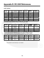
1
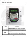
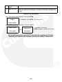
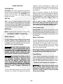
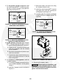
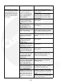
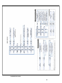
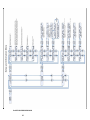
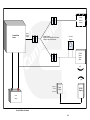
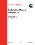
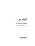
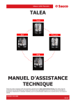
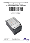
Owner Manual
RV Automatic Generator Controller
Energy Command 30W
(EC-30W)
English
12−2008
A028Z586 (Issue 1)
THIS PAGE LEFT INTENTIONALLY BLANK
Table of Contents
SECTION
PAGE
SAFETY PRECAUTIONS . . . . . . . . . . . . . . . . . . . . . . . . . . . . . . . . . . . . . . . . . . . . . . . . . . . . .
iii
1. INTRODUCTION . . . . . . . . . . . . . . . . . . . . . . . . . . . . . . . . . . . . . . . . . . . . . . . . . . . . . . . . . .
1-1
About this manual . . . . . . . . . . . . . . . . . . . . . . . . . . . . . . . . . . . . . . . . . . . . . . . . . . . . .
1-1
Product Overview . . . . . . . . . . . . . . . . . . . . . . . . . . . . . . . . . . . . . . . . . . . . . . . . . . . . .
1-1
EC-30W Kit Contents . . . . . . . . . . . . . . . . . . . . . . . . . . . . . . . . . . . . . . . . . . . . . . . . . .
1-1
How To Obtain Service . . . . . . . . . . . . . . . . . . . . . . . . . . . . . . . . . . . . . . . . . . . . . . . .
1-1
Warranty Policy . . . . . . . . . . . . . . . . . . . . . . . . . . . . . . . . . . . . . . . . . . . . . . . . . . . . . . .
1-1
2. QUICK REFERENCE . . . . . . . . . . . . . . . . . . . . . . . . . . . . . . . . . . . . . . . . . . . . . . . . . . . . . .
2-1
3. OPERATION . . . . . . . . . . . . . . . . . . . . . . . . . . . . . . . . . . . . . . . . . . . . . . . . . . . . . . . . . . . . . .
3-1
General Overview . . . . . . . . . . . . . . . . . . . . . . . . . . . . . . . . . . . . . . . . . . . . . . . . . . . . .
3-1
Manual Genset Operation . . . . . . . . . . . . . . . . . . . . . . . . . . . . . . . . . . . . . . . . . . . . . .
3-1
Default Display . . . . . . . . . . . . . . . . . . . . . . . . . . . . . . . . . . . . . . . . . . . . . . . . . . . . . . .
3-1
Using the Keys . . . . . . . . . . . . . . . . . . . . . . . . . . . . . . . . . . . . . . . . . . . . . . . . . . . . . . .
3-2
Automatic Genset Operation . . . . . . . . . . . . . . . . . . . . . . . . . . . . . . . . . . . . . . . . . . .
3-2
Using Displays . . . . . . . . . . . . . . . . . . . . . . . . . . . . . . . . . . . . . . . . . . . . . . . . . . . . . . . .
3-3
Power Supply . . . . . . . . . . . . . . . . . . . . . . . . . . . . . . . . . . . . . . . . . . . . . . . . . . . . . . . . .
3-3
4. INSTALLATION . . . . . . . . . . . . . . . . . . . . . . . . . . . . . . . . . . . . . . . . . . . . . . . . . . . . . . . . . . .
4-1
General . . . . . . . . . . . . . . . . . . . . . . . . . . . . . . . . . . . . . . . . . . . . . . . . . . . . . . . . . . . . . .
4-1
Installation Codes and Standards for Safety . . . . . . . . . . . . . . . . . . . . . . . . . . . . . .
4-2
Installation Procedures . . . . . . . . . . . . . . . . . . . . . . . . . . . . . . . . . . . . . . . . . . . . . . . .
4-2
Connections (Definitions) . . . . . . . . . . . . . . . . . . . . . . . . . . . . . . . . . . . . . . . . . . . . . .
4-5
Final Connections and Testing . . . . . . . . . . . . . . . . . . . . . . . . . . . . . . . . . . . . . . . . . .
4-5
AGS Warning Labels . . . . . . . . . . . . . . . . . . . . . . . . . . . . . . . . . . . . . . . . . . . . . . . . . .
4-6
i
5. SETUP & TEST . . . . . . . . . . . . . . . . . . . . . . . . . . . . . . . . . . . . . . . . . . . . . . . . . . . . . . . . . . .
5-1
General . . . . . . . . . . . . . . . . . . . . . . . . . . . . . . . . . . . . . . . . . . . . . . . . . . . . . . . . . . . . . .
5-1
Main Menu . . . . . . . . . . . . . . . . . . . . . . . . . . . . . . . . . . . . . . . . . . . . . . . . . . . . . . . . . . .
5-1
Setup & Information Displays . . . . . . . . . . . . . . . . . . . . . . . . . . . . . . . . . . . . . . . . . . .
5-2
System Information Menu . . . . . . . . . . . . . . . . . . . . . . . . . . . . . . . . . . . . . . . . . . . . . .
5-2
System Setup Menu . . . . . . . . . . . . . . . . . . . . . . . . . . . . . . . . . . . . . . . . . . . . . . . . . . .
5-3
Auto Start Setup Display . . . . . . . . . . . . . . . . . . . . . . . . . . . . . . . . . . . . . . . . . . . . . . .
5-5
6. GENERAL TROUBLESHOOTING . . . . . . . . . . . . . . . . . . . . . . . . . . . . . . . . . . . . . . . . . . .
6-1
Troubleshooting . . . . . . . . . . . . . . . . . . . . . . . . . . . . . . . . . . . . . . . . . . . . . . . . . . . . . . .
6-1
APPENDIX A. OUTLINE AND SYSTEM DRAWINGS . . . . . . . . . . . . . . . . . . . . . . . . . . . . A-1
EC-30W MAIN MENU DISPLAY DIAGRAM . . . . . . . . . . . . . . . . . . . . . . . . . . . . . . . A-2
EC-30W SETUP AND INFORMATION MENU DIAGRAM . . . . . . . . . . . . . . . . . . . A-3
EC-30W SYSTEM BLOCK DIAGRAM . . . . . . . . . . . . . . . . . . . . . . . . . . . . . . . . . . . A-4
APPENDIX B. EC-30W REFERENCES . . . . . . . . . . . . . . . . . . . . . . . . . . . . . . . . . . . . . . . . B-1
ii
SAFETY PRECAUTIONS
• Engine cooling air must not be used for heating
the vehicle.
Thoroughly read this Owner Manual before operating the EC-30W and generator set. Safe operation and top performance can only be obtained when equipment is properly operated
and maintained.
GENERATOR VOLTAGE IS DEADLY
• Generator electrical output connections must
be made by a trained and experienced electrician in accordance with applicable codes.
The following symbols in this manual alert you to
potential hazards to the operator, service person
and equipment.
• The generator set must not be connected to
shore power (utility). Back-feed to shore power
can cause electrocution and damage to equipment. An approved switching device must be
used to prevent interconnections.
alerts you to an immediate hazard
that will result in severe personal injury or
death.
DANGER
• Use caution when working on live electrical
equipment. Remove jewelry, make sure clothing and shoes are dry, stand on a dry wooden
platform or rubber insulating mat and use tools
with insulated handles.
WARNING alerts you to a hazard or unsafe
practice that can result in severe personal injury or death.
CAUTION alerts you to a hazard or unsafe
practice that can result in personal injury or
equipment damage.
DIESEL, GASOLINE, AND PROPANE FUEL
IS COMBUSTIBLE
Exhaust, electricity, fuel, moving parts and batteries present hazards which can result in severe personal injury or death.
• Do not smoke or turn electrical switches ON or
OFF where fuel fumes are present or in areas
sharing ventilation with fuel tanks or equipment. Keep flames, sparks, pilot lights, arcproducing equipment and all other sources of
ignition well away.
ENGINE EXHAUST IS DEADLY
• Inspect for exhaust leaks at every startup and
after every eight hours of running.
• Fuel lines must be secured, free of leaks and
separated or shielded from electrical wiring.
• Learn the symptoms of carbon monoxide poisoning in the generator set Operator’s Manual.
• Never sleep in the vehicle while the generator
set is running unless the vehicle is equipped
with a working carbon monoxide detector.
MOVING PARTS CAN CAUSE SEVERE
PERSONAL INJURY OR DEATH
• Do not wear loose clothing or jewelry near
moving parts such as fans and other moving
parts.
• Do not operate the generator set when the vehicle is parked in a confined space, such as a
garage.
• Keep hands away from moving parts.
• The exhaust system must be installed in accordance with the generator set Installation
Manual.
• Keep guards in place over fans and other moving parts.
iii
BATTERY GAS IS EXPLOSIVE
batteries to prevent starting during maintenance and service. (Always disconnect negative [−] first and reconnect last to prevent
sparks between tools and vehicle frame.)
• Wear safety glasses.
• Do not smoke.
• To reduce arcing when disconnecting or reconnecting battery cables, always disconnect
the negative (−) battery cable first and reconnect it last.
• Keep the generator set and its compartment
clean. Excess oil and oily rags can catch fire.
Dirt and gear stowed in the compartment can
restrict cooling air.
• Make sure all fasteners are secure and
torqued properly.
FLAMMABLE VAPORS CAN BE IGNITED
BY OPERATION OF COACH ELECTRICAL
SYSTEMS AND CAUSE DIESEL ENGINES
TO OVERSPEED
• Do not work on the generator set when mentally or physically fatigued or after consuming
alcohol or drugs.
• Stop the generator set before fueling the
coach to reduce the risk of igniting flammable
vapors.
• You must be trained and experienced to make
adjustments while the generator set is running—hot, moving or electrically live parts can
cause severe personal injury or death.
• Do not operate the diesel-powered generator
set where there are or can be flammable vapors created by fuel spills, gas leaks, etc.
Flammable vapors drawn into a diesel engine
air intake system can cause the engine to overspeed, which can result in fire, explosion and
equipment damage. The owners and operators of the generator set are solely responsible for safe operation.
• Used engine oil has been identified by some
U. S. state and federal agencies as causing
cancer or reproductive toxicity. Do not ingest,
inhale, or contact used oil or its vapors.
• Do not use evaporative starting fluids. They
are highly explosive.
• Keep multi-class ABC fire extinguishers readily at hand. Class A fires involve ordinary combustible materials such as wood and cloth.
Class B fires involve combustible and flammable liquids and gaseous fuels. Class C fires
involve live electrical equipment. See NFPA
No. 10 (Portable Fire Extinguishers) or equivalent—BS EN 3-7:2004.
• To prevent accidental or remote starting while
working on the generator set, press the Stop
button and disconnect the battery cables at the
• Generator set installation and operation must
comply with all applicable local, state and federal codes and regulations.
GENERAL PRECAUTIONS
• Keep children away from the generator set.
iv
1. Introduction
ABOUT THIS MANUAL
EC-30W KIT CONTENTS
The following are the EC–30W kit contents:
This manual provides the operation and installation
instructions for the EC-30W (Energy Command 30
Wireless). This system is compatible with Cummins
Onan Recreational Vehicle gensets (Quiet Diesel
generator sets, gasoline/ liquid propane generator
sets). This manual does not have instructions for
servicing printed circuit board assemblies. Generator set service instructions are in the applicable
genset operation, service, and installation manuals.
EC-30W display and cradle
EC-30W genset module
Nickel metal hydride rechargeable battery
Rechargeable battery charger (5V DC
Power Supply)
AGS Warning Labels
HOW TO OBTAIN SERVICE
If service, parts, or product literature is required,
contact the nearest Cummins Onan dealer or distributor.
In
the
US
or
Canada,
call
1−800−888−ONAN for name and telephone. By
calling this number, you may also request a directory of authorized RV servicing dealers:
Read the Safety Precautions thoroughly and observe all instructions and precautions in this manual.
RV Sales and Service Directory: F−919.
This manual contains basic wiring diagrams for the
EC-30W and its connection to the accompanying
genset.
Before calling for service, have the following information available:
1. Complete model number and serial number of
product
Keep this manual with other genset manuals.
2. Software version number, as shown in the
SYSTEM INFORMATION displays
3. Date of purchase
PRODUCT OVERVIEW
WARNING Incorrect service or replacement of
parts can result in severe personal injury or
death, and/or equipment damage. Service personnel must be qualified to perform electrical
and mechanical service. Read and follow Safety
Precautions on page ii and throughout the
manual.
The EC-30W is an AGS (Automatic Generator
Starting System) that provides wireless, automatic,
and manual control of Cummins Onan Diesel, Gas,
and LP (Liquid Propane) engine−driven AC gensets. The EC-30W automatically starts the genset
when the battery becomes discharged or when
temperatures exceed user settings. When the battery is charged, or the temperature sensor indicates the HVAC (Heating, Ventilating, and Air Conditioning) system no longer requires power, the
EC-30W will automatically turn off the genset.
WARRANTY POLICY
For complete Cummins Onan Limited Warranty details, contact your Cummins Onan RV Service and
Parts dealer or call 1−800−888−ONAN (6626).
1-1
THIS PAGE LEFT INTENTIONALLY BLANK
1-2
2. Quick Reference
7
8
1
6
2
3
5
4
NO.
ITEM NAME
ITEM DESCRIPTION
1
BACK BUTTON
This key is used to return to previous screen.
2
SET BUTTON
This key is used as the forward key to navigate through the menu and to display and change settable values, such as: Local Time, Quiet Time Start and
End (QT Start and QT End).
3
START BUTTON
Works similar to the genset start/stop switch.
4
AUTO BUTTON
This key enables/disables automatic genset operating mode. LED indicates if
AGS is enabled.
5
STOP/PRIME
BUTTON
Works similar to the genset start/stop switch.
6
UP/DOWN BUTTON
This key is used to scroll through display choices and change values that can
be set.
2-1
7
SHORE LED
LIGHT
Light on if shore power present
8
GEN LED LIGHT
Status light powers on when genset is running, flashes during cranking, preheating and genset fault messages. This light works similar to the genset status light.
FIGURE 2-1. EC−30W DISPLAY
Note: Start requires two keystrokes. First press SET:
SET to
…is displayed. Press SET once again to start.
START GENSET
Note: AUTO requires two keystrokes. First press AUTO :
SET to Enable
SET to Disable
OR
AUTO START
…is displayed. Next press
SET to enable or disable AUTO mode.
AUTO START
Do not start genset or select AUTO mode before reading and understanding this manual and without following its Safety Precautions!
2-2
3. Operation
GENERAL OVERVIEW
If other AGS systems are present, disconnect the
systems before installing the EC–30W.
This section describes how to use the EC–30W.
Ensure all safety precautions and items have been
read before operating this product.
MANUAL GENSET OPERATION
START & STOP/PRIME Buttons
BEFORE SERVICING, ALWAYS DISABLE AGS BY DISCONNECTING BATTERY OR
GENSET REMOTE HARNESS.
The EC–30W START & STOP/PRIME buttons are
used to manually start and stop the genset.
Improper Service or replacement of
parts can result in severe personal injury,
death, and/or equipment damage. Service personnel must be experienced to perform electrical and/or mechanical service.
Holding the STOP button for 3 seconds when the
EC–30W set is not running will activate PRIME.
The genset START/STOP buttons will act identically to the remote status rocker switch except that the
user does not need to hold the START button until
the set is running to start the genset.
CAUTION
WARNING
Severe personal injury, death, and
equipment damage can result from operating
the genset in a garage, building, or confined
space. The genset produces dangerous fumes
when it is running. Never start the genset when
the recreational vehicle is in a garage, building,
or confined space.
WARNING
When the EC–30W START or STOP switch is operated, the EC–30W AGS operating mode is disabled.
The genset may be started using the remote
START/STOP switch even if there is no power to
the EC–30W. Once the genset is running, the
EC–30W display will turn on if charger is plugged in
to the display.
ENGINE EXHAUST GASES CAN BE
DEADLY. Verify carbon monoxide alarm is
installed and functional in your vehicle before
starting generator or enabling AGS. All engine
exhaust contains carbon monoxide; an odorless, colorless gas that can cause severe personal injury or death. Symptoms of carbon
monoxide poisoning include:
WARNING
DEFAULT DISPLAY
Low Power Mode
The display module’s default state will be low power
mode to conserve battery power.
• Dizziness
• Headache or Throbbing Temples
• Weakness or Muscular Twitching
• Sleepiness or Confusion
• Nausea or Vomiting
During low power mode, the display will turn off.
Low power will resume 2 minutes after last key−
press. In this mode, the wireless display will go into
a cyclic sleep mode: waking once every minute to
send data to the genset module and to receive status from the genset module, followed by resumed
sleep.
IF YOU EXPERIENCE ANY OF THESE SYMPTOMS, GET INTO FRESH AIR IMMEDIATELY. If
symptoms persist, seek medical attention. Shut
down the genset and do not operate until inspected and repaired.
The display will turn on after any key is pressed on
the interface.
3-1
USING THE KEYS
measures motion (acceleration) to detect if the
coach may have been moved to an enclosed location where there is a danger of CO poisoning and
accumulation.
UP/DOWN Key
UP/DOWN key is used to navigate through the display menu and to change values or parameters that
can be set by the user. If the UP/DOWN key is
pressed and held down, the display will scroll
through the values.
When the motion is detected, the EC–30W disables the AGS. This prevents unexpected automatic starting indoors or in confined spaces. Verify the
vehicle is parked in a safe location, and then use
the AUTO key, followed by SET to enable the
AGS.
SET Key
SET is used for forward navigation and to select
values that can be changed by the user. Examples
include: Local Time, start of Quiet Time, and end of
Quiet Time. Pressing the SET key will cause the
value to flash (if it can be changed).
Note: In order to enable or disable the EC–30W
AUTO START (AGS) mode, there is a confirming keystroke required (AUTO key then SET to confirm).
This reduces risk of unintended auto operation.
Verify Safety Input
BACK Key
Accelerometer: The sensor in the genset module
that measures motion (acceleration) to detect if the
coach may have been moved to an enclosed location where there is a danger of CO poisoning and
accumulation.
BACK is used to return to previous menu screen.
AUTOMATIC GENSET OPERATION
Safety Features
Motion Verification
The EC–30W has safety features to help prevent
automatic operation when it may be unsafe. Each
time the vehicle is moved, the AGS operating mode
is disabled Only if the vehicle is in a safe location
should the AGS function be enabled.
The EC–30W maintains a record of the last motion.
If the EC–30W does not see any motion in 30 days,
it will disable the AGS and prompt the user to re−
verify the motion by walking on the coach, driving
the coach, manually starting the generator, or tapping on the genset module.
WARNING DO NOT RUN THE GENSET OR ENABLE THE EC–30W AGS MODE WHEN THE RV
IS INDOORS OR IN A CONFINED SPACE. ASPHYXIATION OR CARBON MONOXIDE POISONING HAZARDS EXIST WHEREVER GENSET EXHAUST GASSES CAN ACCUMULATE.
Note: During verification, if at least one of the values
is not 0 (zero) in the motion data screen, motion is
successfully verified and 30−day timer is reset.
Crank/Startup
WARNING THIS GENSET/CONTROL IS NOT A
LIFE SUPPORT SYSTEM. IT CAN STOP WITHOUT WARNING. CHILDREN, PERSONS WITH
PHYSICAL OR MENTAL LIMITATIONS, AND
PETS COULD SUFFER PERSONAL PERSONAL
INJURY OR DEATH. A PERSONAL ATTENDANT,
REDUNDANT POWER OR ALARM SYSTEM
MUST BE USED IF GENSET OPERATION IS
CRITICAL.
To start, Gas/LP gensets take up to typically 18 seconds of cranking while Diesel gensets take 30 seconds of cranking. If genset does not start on the first
time, EC–30W waits 30 seconds before re−crank.
Maximum crank attempts for all gensets: 3.
Care should be taken while changing the settings. These settings should only be
changed by qualified personnel that understand the charging system and have checked
its operating voltages.
CAUTION
The EC–30W safety feature has a built in Accelerometer. It is a sensor in the genset module that
3-2
Adaptive Cycle Management
If (down) arrow is present, there is/are additional menu screen(s) below current screen.
Limiting Short Cycling
If (left) arrow is present, but not the (right) arrow, there is not a following screen.
When in the automatic mode, the EC–30W observes a minimum run-time of 10 minutes, even if
the automatic run request has been satisfied. For
example, suppose the HVAC (air conditioner) only
needs to run for 6 minutes to cool the coach enough
to satisfy the temperature sensor threshold. The
genset will still continue to run for a minimum of 10
minutes before stopping.
If (right) arrow is present on the screen, there is
a proceeding menu screen.
“Service In” & “Gen Hrs” Display
The “Service In” line is a countdown service hour
meter that indicates the genset’s next required service interval. The genset hour−meter displays the
total elapsed time the genset has run since the
EC–30W was installed.
If a new run request is detected, during the minimum run, the Adaptive Cycle Management feature
will limit short cycling by extending the run time as
required.
If the EC–30W is installed on an existing genset,
see the SETUP section of this manual. To determine specific service items, see the genset manual.
Quiet Time Prefill
When the service interval has elapsed, the display
will show:
Two hours prior to the beginning of Quiet Time the
EC–30W checks the battery level, and if the batteries are not full, the EC–30W will start the genset to
charge the batteries.
SERVICE DUE
Preventing Automatic Starting When Connected to Shore AC
The SERVICE DUE message is displayed as
soon as the service interval has elapsed.
The EC–30W has an input to prevent the genset
from automatically starting when connected to
shore power. For this feature to be active, the cord
supplied must be plugged into a non−inverter powered outlet. The Installation section of this manual
describes how this feature is installed.
The EC-30W calculates the service hours based on
the genset type, genset hour−meter, and last time
service hours were set. Verify that the genset type
and genset hours are set correctly. Remember toreset service in hours after genset is serviced.
USING DISPLAYS
After the genset is serviced, navigate to the “Service In“/“Gen Hrs” display, press SET to reset
Service Interval. Press SET again to reset the
service interval hour-meter.
To satisfy FCC RF exposure requirements for mobile transmitting devices, a
separation distance of 20 cm or more should be
maintained between the antenna of this device
and persons during device operation. To ensure compliance, operations at closer than this
distance is not recommended. The antenna
used for this transmitter must not be co−located in conjunction with any other antenna or
transmitter.
WARNING
POWER SUPPLY
EC–30W Genset Module
This unit operates with input voltage between
7-17VDC (12VDC nominal battery).
The display is used to show key system information.
Note: The purple wire is positive and needs to be
connected to the House Battery for low battery AGS
operatioin to work properly.
Arrows in Display Screens
EC–30W Display
Only if (up) arrow is present, there is/are additional menu screen(s) above current screen.
The display comes with a Nickel Metal Hydride battery that is rechargeable (takes approximately 3
3-3
hours to fully charge). After charging the battery to
full, the battery can power the display 2-7 days depending on battery age and display usage.
genset is started when the bar graph only shows
two segment and stopped when four bars are displayed.
The rechargeable battery loses its energy during
storage, even without loading. As the battery loses
energy during storage, the voltage also drops. In
general, the battery capacity loss due to self−discharge during storage can be recovered by recharging. If the battery is stored for over six months
it is advised that the battery be cycled several times
to resume the battery capacity.
House Battery Voltage
The house battery voltage can be used to assess
the performance of the charging system and to estimate the battery SOC.
To estimate battery SOC, no loads should be on
and the battery should not be charging. The battery
should have “rested” in this state for 24 hours. If the
battery rests for only 30 minutes, the SOC estimate
will be less accurate.
Regular AA batteries can also be used to power the
display.
House Battery Charge Level Indicator
TABLE 3-1. OPEN CIRCUIT VOLTAGE VS. SOC 12
VOLT BATTERIES OF VARIOUS TYPES
STATE OF BATTERY ELECTROLYTE TYPE
CHARGE
LIQUID
AGM
GELLED
100%
12.6
12.9
12.8
75%
12.4
12.7
12.6
50%
12.2
12.4
12.3
25%
12.0
12.0
12.0
0%
11.8
11.8
11.8
The house battery charge level indicator uses both
short- and long-term voltage trends to determine
the battery level. It is intended as a guide to the
SOC (state of charge) of the battery and its ability to
sustain the load.
When the EC–30W is in the automatic mode, it also
serves as the default trigger points for starting and
stopping the genset to charge a low battery. The
3-4
4. Installation
GENERAL
(−) battery cable is connected and a tool being
used to connect or disconnect the positive (+)
battery cable accidentally touches the frame or
other grounded metal part of the genset set or
vehicle frame. To prevent arcing, ALWAYS remove the negative (−) cable first, and reconnect
it last.
This section describes how to install the EC-30W.
This system is only for use with Cummins Onan
Recreational Vehicle genset (Quiet Diesel, Gasoline and LP gensets).
The control circuitry is a 3−wire ground to start/stop
type. Consult a Cummins Onan distributor with any
questions.
TABLE 4-1. SPECIFICATIONS
Display
The Appendices show the Cummins Onan gensets
that are compatible with the EC-30W and the correct wiring figures and harnesses to use for each
genset.
Operating
−4F to 122F
Temperature: (−20C to
50C)
Genset Module
−4F to 158F
(−20C to
70C)
Storage Tem- −22F to 176F −40F to 176F
perature:
(−30C to
(−40C to
80C) exclud- 80C)
ing battery
WARNING Improper Service or replacement of
parts can result in severe personal injury,
death, and/or equipment damage. Service personnel must be trained and experienced to perform electrical and/or mechanical service.
Always disconnect a battery charger from its AC source before disconnecting
the battery cables. Otherwise, disconnecting
the cables can result in voltage spikes high
enough to damage the DC control circuits of the
genset.
Battery Life:
2−7 days between charge
cycle
Nominal Current Draw
−−
CAUTION
Unexpected starting of the genset
while working on it can cause severe personal
injury or death. Prevent unexpected or accidental starting by disconnecting the genset battery
cables [negative (−) first], or by disconnecting
the remote harness at the genset.
WARNING
WARNING Arcing can ignite explosive hydrogen gas given off by batteries, causing severe
personal injury. Arcing can occur if the negative
4-1
50mA (at 12
Vdc)
Operating
Voltage
Range:
2−5 Vdc
7−17VDC
Protection:
Reverse polarity protected,
short circuit protected
Operating
Frequency
Band:
ISM 2.4 GHz
Communication Range:
150 ft. Max
INSTALLATION CODES AND STANDARDS
FOR SAFETY
1. Disconnect the negative (−) cable from the battery terminal to prevent accidental starting.
EC-30W is suitable for installation in accordance
with:
2. Select a location in RV for the display. Location
should be in a visible location near a non−inverter outlet for shore power detection and
where operation will be convenient.
ANSI A 1192 (NFPA No. 1192)−Standard on
Recreational Vehicles
CAUTION Check the backside (inside) of
the chosen location to verify that nothing
will interfere with drilling, or with the fasteners or harness plug of the EC-30W.
CAN/CSA−Z240.6.2 Recreational Vehicles
FCC15
RoHS Compliant
CAUTION Wires must be protected from
all hot, sharp, and abrasive surfaces. Use
protective sheathing where necessary to
protect the wires from sharp edges.
Federal, State and local codes, such as the California Administrative Code—Title 25 (RV installation),
might also be applicable. Installation codes and
recommendations can change from time-to-time
and are different in different countries, states and
municipalities. Obtain the standards in Table 4-2 for
reference.
CAUTION The display cradle should be
mounted in a protected environment, away
from excessive heat and cold.
3. Attach the display cradle to a smooth and dry
surface using the included double−stick tape
or drill holes into location of where display
cradle will be set.
TABLE 4-2. REFERENCE CODES AND
STANDARDS
NFPA No. 70
NFPA N0. 501C
National Fire Protection Association
470 Atlantic Avenue
Boston, MA 02210
ANSI A119.2
ANSI/RVIA-EGS-1
FMVSS 301
Recreational Vehicle Industry Association
14650 Lee Road
Chantily, VA 22021
California Administrative Code—Title
25, Chapter 3
State of California Documents Section
P.O. Box 1015
North Highlands, CA 95660
CAN/CSA-Z240
Recreational
Vehicles
Bulletin 946
Canadian Standards Association
Housing and Construction Materials Section
178 Rexdale Blvd.
Rexdale, Ontario, Canada M9W 1R3
Mount the display cradle near a non−inverter
powered outlet, as permitted by the length of
the charger cord.
Ensure you do not drill into other electrical components.
CAUTION
4. Apply adhesive tape to clean and dry surfaces
>50 degrees F only. Adhesive bond will reach
75% maximum adhesion strength in 1 hour,
100% in 72 hours.
Note: For maximum hold, allow the tape to
cure at least one hour before subjecting to
any level of vibration. Not doing so will
cause cradle and display to fall, resulting in
possible damage.
INSTALLATION PROCEDURES
Mounting EC-30W Display
5. Install the battery pack into the back of the display.
Do not mount display in direct sunlight or near heat source or cold air. Doing so
will incur equipment damage and inappropriate
AGS operation.
CAUTION
6. Put display in cradle and plug in supplied display battery charger provided.
4-2
Genset Module Installation
Always disconnect a battery charger from its AC source before disconnecting
the battery cables. Otherwise, disconnecting
the cables can result in voltage spikes high
enough to damage the DC control circuits of the
genset.
CAUTION
WARNING Exhaust gases are hazardous and
may cause severe personal injury or death.
Seal all holes to prevent the entrance of exhaust
gasses into the vehicle interior.
1. Turn off genset and disconnect battery cables/
power to prevent accidental starting.
Check the backside (inside) of
the chosen location to verify that nothing
will interfere with drilling, or with the fasteners or harness plug of the EC-30W.
CAUTION
Wires must be protected from
all hot, sharp, and abrasive surfaces. Use
protective sheathing where necessary to
protect the wires from sharp edges.
CAUTION
FIGURE 4-1. GENSET MODULE (INTERIOR)
CAUTION Ensure you do not drill into other electrical components.
2. Find proper location to mount module. Ensure
there will be no obstructions for installation, operation, and future handling.
5. Apply adhesive tape to clean and dry surfaces
>50F only. Adhesive bond will reach 75%
maximum adhesion strength in 1 hour, 100%
in 72 hours.
DO NOT MOUNT MODULE ON
TO GENSET! DOING SO WILL INCUR
EQUIPMENT DAMAGE AND INAPPROPRIATE AGS OPERATION.
Note: For maximum hold, allow the tape to
cure at least one hour before subjecting to
any level of vibration. Not doing so will
cause cradle and display to fall, resulting in
possible damage.
CAUTION
3. Mount the genset module near the genset, as
permitted by the genset module wiring harness.
6. For installations that do not require a Y−adapter harness, plug the control harness J8 connector directly into the remote harness connector on the genset.
The genset module should be
mounted in a protected environment, away
from excessive heat and cold, excessive
road spray, water, and heat sources.
CAUTION
7. For installations on gas gensets that require
a Y-adapter harness, install the harness.
A. Unplug the harness connected to the remote harness connector on the genset.
4. Either drill holes as shown in Figure 4-1 or else
attach the genset module to a smooth and dry
surface using the included double−stick tape.
B. Install the Y-adapter harness, as shown in
Figure 4-2 or Figure 4-3.
4-3
C. Extend the battery connection wire using
the included extension wire.
8. For all gasoline gensets except KV, install
the control harness BATT+ terminal ring (purple wire) on the B+ terminal on the start solenoid relay (see Figure 4-2).
D. Install the control harness BATT+ terminal
ring (purple wire) on the B+ terminal post
on the genset (see Figure 4-5).
REMOTE
CONNECTION
TO
REMOTE
START/
STOP
J8
EC-30W
J8
E. If present, plug the connector unplugged
in step 5A into the Y-adapter harness P8
connector.
P8
J8 P8
GENSET
P9
Y-ADAPTER
HARNESS
FIGURE 4-2. Y-ADAPTER HARNESS BLOCK DIAGRAM FOR KV GAS GENSETS
J8
EC-30W
J8
EC-30W
J8
P8
J8 P8
GENSET
P9
FIGURE 4-4. Y-ADAPTER HARNESS BLOCK DIAGRAM FOR DIESEL GENSETS
P8
J8 P8
J8
Y-ADAPTER
HARNESS
REMOTE
CONNECTION
TO
REMOTE
START/
STOP
REMOTE
CONNECTION
TO
REMOTE
START/
STOP
GENSET
P8
Y-ADAPTER
HARNESS
FIGURE 4-3. Y-ADAPTER HARNESS BLOCK DIAGRAM FOR OTHER GAS GENSETS
9. For KV gensets, connect the control harness
BATT+ terminal ring and the battery positive
(+) cable to the wiring harness B+ connection.
A. Tighten the B+ connection securely and
cover the connection with the terminal
boot to insulate it.
B. Wire-tie the terminal boot in place to prevent boot movement.
C. Connect the remote control harness connector to the mating connector on the left
side of the genset.
B+ TERMINAL
POST
10. For installations on diesel gensets, install the
Y-adapter harness.
FIGURE 4-5. B+ TERMINAL ON DIESEL GENSETS
11. Reconnect the battery cables.
A. If a harness is already connected to the remote harness connector on the genset,
unplug it.
WARNING Exhaust gases are hazardous and
may cause severe personal injury or death.
Seal all holes to prevent the entrance of exhaust
gasses into the vehicle interior.
B. Install the Y-adapter harness, as shown in
Figure 4-4.
4-4
CONNECTIONS (DEFINITIONS)
FINAL CONNECTIONS AND TESTING
This section describes each connection to the
EC-30W.
This section describes the final connections and
test procedure to verify the unit has been installed
correctly and is operating properly.
Genset Connections
Ensuring Generator and EC-30W
Connection to House Battery
WIRE A BATTERY GROUND (NEGATIVE): This
wire supplies the ground or negative side of the circuit for the EC-30W genset module. It must be supplied from the genset.
Ensure that the generator set and EC-30W is connected to the house battery, not the engine battery.
1. Remove the negative battery cable for the
house battery bank.
WIRE B STOP/PRIME INPUT: This wire supplies
the stop/prime signal to the genset. It is an active
low or grounded output.
2. Press the start button on the generator to verify
the generator doesn’t crank.
WIRE C START/PREHEAT: This wire supplies the
start/preheat signal to the genset. It is an active low
or grounded output.
If the generator cranks, then the DC connection to the generator is from an alternate set of
batteries, such as the Chassis Battery bank.
WIRE E SWITCHED B+ FROM GENSET: This wire
is switched to the battery positive voltage when the
genset is running. It is used on the genset node to
indicate the genset is running.
If the battery bank is connected to the chassis
batteries the connection to the generator will
have to be altered to the House batteries to ensure correct AGS functions due to low battery
conditions.
WIRE F Genset Status Light: This wire supplies a
diagnostic output from the genset that flashes the
red light in the START/STOP switch to indicate a
genset fault. The status light output is decoded by
the EC-30W to display a fault code.
If the generator does not crank then the generator must be connected to the House Batteries.
3. Reconnect the negative terminal to the House
Battery bank and check Converter/Inverter operation for correct charge.
Power and Communication Connections
Please contact your closest authorized Cummins
Onan Facility for more information on how to properly ensure your generator set and EC-30W is connected to the house battery, and not the engine battery.
12VDC Power Wire (purple wire): This wire is the
positive power supply to the EC-30W.
WIRE G & H: Serial communication wires to genset. Not required.
Test EC-30W Connection
TT+ (faston receptacle): This is a wire splice into
Run input lead for an optional hour−meter.
The following test procedure describes a systematic method of testing both the installation and operation of the EC-30W.
TT− (faston receptacle): This is a wire splice into
Ground lead for an optional hour−meter.
Initial Synchronization
Sensing AC Shore Power
The EC-30W should be initially synched.
The UL Listed 120VAC to 5VDC plug−in power supply is equipped with the EC-30W kit. This input is
used to prevent the genset from automatically starting when AC Shore Power is connected.
1. When a button is pressed, display powers on
and will read, “Establishing Communication.”
The main screen will appear showing the time.
If screen does not show time, following the proceeding steps.
CAUTION Do not connect 120VAC or 240VAC
line voltage to the EC-30W! Damage will occur
and will not be covered by warranty!
2. From the Main Menu, navigate to “Setup and
Information” screen and press SET.
4-5
3. Press or arrow until “System Setup”
screen is reached.
D. Use the UP/DOWN switch to the right of
the display to scroll to the house battery
display and confirm that it is showing the
house battery voltage.
4. Press SET to proceed.
5. Press or arrow until “Synchronize to
Genset Module” appears.
E. Navigate to one of the screens which
shows house temp and verify the temperature shown on the EC-30W is roughly the
same as the temperature displayed by a
separate thermostat inside the coach. The
temperature shown by the thermostat and
EC-30W display might not be exactly the
same as what is on the EC-30W, however
the temperatures should be reasonably
close to one another.
6. Press SET. The next screen will read, “Preparing for Synchronization.”
7. When display appears, hold STOP at genset to
synchronize. Press and hold the stop switch at
genset or remote START/STOP.
8. If device is synchronized, message will appear,
“Synchronized to Genset Module.”
9. Set GEN HRS and TYPE. (See Table below for
Genset Types.)
F. Plug in supplied 5VDC adapter and confirm shore LED light is on.
A. Use the or arrow to change values.
3. Stop the genset at the controller and check the
following:
B. Press SET to advance to next editable value.
A. The genset stops
TABLE 4-3. GENERATOR TYPES
GEN TYPE
MODEL
SERVICE IN
NOT SET
−−−
−−−
QD 10/12
RV QD 10000
RV QD 12500
250
QD 5-8
RV QD 8000
RV QD 6000
150
RV QG 5500−
2200
RV QG
3600−4000
150
RV QG
2500−2800
150
GAS/LP
GAS/LP-KV
B. The hour−meter stops
C. GEN LED light turns off
4. Set the clock to the current local time as described on page 5-1.
AGS WARNING LABELS
The unit includes a sheet of adhesive warning labels. Affix one label at or near each of the following
locations:
Genset Service Access Panel
Genset Start/Stop Switch
Vehicle AC Distribution Panel
Vehicle AC Transfer Switch
10. Press BACK to return to main screen.
For towed RV, tow tongue or tongue jack
Test EC-30W Operation
WARNING
1. Start and stop the genset using the STOP/
START switch located on genset. This confirms the genset operation.
Auto Genset Starting (AGS) installed.
2. Start the genset at the EC-30W display and
check the following:
Carbon−monoxide (CO), moving parts, and
shock can cause severe injury or death.
Disconnect battery or remote harness at
genset to store or garage RV and before
servicing genset or RV electrical systems.
A. LED on generator module to indicate power connection
B. Genset starts and continues to run
C. Display GEN LED light is on.
FIGURE 4-6. AGS WARNING LABEL
4-6
5. Setup & Test
General
5. Use or key to set temperature from
32-99F.
This section describes how to Setup and Test the
EC-30W. Before using the EC-30W for the first
time, check to be sure that the unit is setup appropriately for the system.
Note: Default temperatures are 68F (Heat)
and 74F (Cool).
6. Press BACK to return to previous screen on
main menu.
MAIN MENU
Setting “Service In & Gen Hrs”
Setting Time
To set “Service In & Gen Hrs.”:
1. On the main screen, navigate to “Service &
Gen Hrs” screen by using the or key.
To set the local time:
1. From the main screen, navigate to screen
where time and house temperature is shown.
2. Press SET.
3. Press SET again to reset service interval.
2. Press SET to enter editing screen. Note that
the hour digit flashes.
Setting QT (Quiet Time) Start & End
3. Use the or key to change time.
The Local Time is used to prohibit automatically
starting the genset during Quiet TIme. The QUIET
TIME mode prohibits the genset from automatically
starting between the start and end of Quiet Time.
4. Press SET to go to the minute field. Use the
UP/DOWN keys to change.
5. After time is set, press BACK to go to previous
screen.
To change these times:
Setting Auto Temperature (AUTO TEMP)
1. Press or key to navigate to the QUIET
TIME display.
To set the Auto Temp.
2. The current setting is shown. Press SET to
change the setting.
1. On the main screen, navigate to “Auto Temp”
screen by using the or key.
2. Press SET.
3. Use the or key to change the value to on
or off.
3. “Auto Temp Start” will appear on display. Select proper setting: Cool, Off, or Heat by using
the or key.
4. Press the SET button to move from one field
to another, and to set the start and end for
Quiet Time.
4. Press SET
5. Press BACK to go to previous screen.
to move to temperature field.
5-1
Setup & Information Displays
SYSTEM INFORMATION MENU
The Setup & Information displays are used to tailor
the EC-30W to the particular system and application.
The System Information menu shows the: Genset
Status, Last Auto Even, Last Fault, Display
SWVx.xx/Base SWVx.xx, and Motion Data.
See EC-30W Setup & Information Display Diagram
in Appendix A for reference.
Genset Status Display
The genset status display shows the genset status:
“Fault,” “Starting,” “Running,” “Stopped,” and
“Priming.”
Access Setup & Information Displays
1. From the main menu, use or key to navigate to the Setup and Information display and
press SET.
LAST AUTO EVENT Display
The LAST AUTO EVENT display allows access to
key information. Pressing SET once will display the
reason for last automatic action. Typical displays
are shown below in Table 5-1:
2. Navigate with or key.
3. Press SET to exit display to continue
through the previous displays.
TABLE 5-1. AUTO EVENTS
Because…
Genset…
AGS…
User disabled AGS
User manually started/stopped Genset
No other AGS events after last AGS enable
Stopped if running
−−
Stays stopped
Disabled
Stopped if running
Stopped if running
Quiet Time Stop
EC-30W detected motion
Display and genset module no longer communicating
Quiet time began
Battery Start
House battery low
Started
Battery Stop
House battery full
Stopped
Temp. Start
Temperature exceeded user set limits (heat or cool)
Started
Temp. Stop
Temperature is back to user set limits (heat or cool)
Auto Temperature Start changed to Off
Genset fault
Display is sensing out-of-range temperature
Accelerometer (motion sensor) diagnostics failed
House battery not full two hours prior to the beginning of quiet time
House battery full prior to the beginning of quiet time
Stopped
Stopped if running
Stopped if running
Stopped if running
Stays stopped
Started
Genset running continuously for 12 hours, but house
battery still not fully charged
Genset running continuously for 24 hours, but temperature still not in user-set limits (heat or cool)
EC-30W commanded genset to stop, but genset
didn’t stop
EC-30W commanded genset to start for three times,
but genset didn’t start
EC-30W didn’t detect any motion in last 30 days
Display battery is low for AGS to work appropriately
EC-30W Genset Status changed to Stopped" without EC-30W stop command, genset stop switch
press, or genset fault indication
Stopped
Stays enabled
Stays enabled
Stays enabled
Stays enabled
Stays enabled
Disabled
Disabled
Disabled
Stays enabled
Stays enabled
Disabled
Stopped
Disabled
Stays running
Disabled
Stays stopped
Disabled
Stopped if running
Stopped if running
Stopped if running
Disabled
Disabled
Disabled
Last Auto Event
display shows…
Manual Disable
Enabled
Motion Disable
Comm. Disable
Gen. Fault Stop
Invalid Temp.
Motion Fault
Pre−fill Start
Pre−fill Stop
Max Charge Time
Max Temp. Time
Failed To Stop
Failed To Start
Verify Motion
Display Battery
Unexpected Stop
5-2
Stopped
Stopped
Stays enabled
Disabled
Disabled
Last Fault #X Display
Set Gen Hour Display:
If the EC-30W is installed on an existing
genset, check the hour-meter on the genset and record the reading.
This displays the last fault received by the module.
See genset operator’s or service manual for fault
number specific troubleshooting information.
A. Use the SET button to advance through
the numeric placements, use the or key to set the correct hour setting.
Display SWVx.xx/Base SWVx.xx
B. Press the BACK button to save your settings and exit the screen.
The DISPLAY SWV shows the version control number for the display. The BASE SWV display shows
the version control number for the EC-30W genset
module. Should it be necessary to contact customer service this number would help determine the
specific configuration of your EC-30W.
The value is stored in permanent memory
and will not have to be changed unless the
EC-30W is installed on a different genset.
The hour−meter in the EC-30W and the
hour−meter at the genset may differ
slightly over time due to small differences in accuracy. However, there
should not be any complications
caused by this.
SYSTEM SETUP MENU
The Sytem Setup menu allows users to set genset
hrs and genset type, unit of temperature (F or C).
It also allows syncronization to the genset module
after initial setup.
Set Gen Type:
If no GEN TYPE has been selected, the display will read:
Set Gen Hrs and Gen Type Display
GEN HRS: 12345.6
The “Gen Hrs and Type” display is used to select
the type of genset used with the EC-30W and to adjust the genset hour meter.
TYPE: NOT SET
C. Press the or key to select the correct
genset hour and genset type. Refer to the
table below for correct genset type.
Setting the gen type is required for proper operation. The very first time the EC-30W is turned on
(power applied) an initial setup procedure begins.
The EC-30W requires setup of both the Gen TYPE
and synchornization prior to allowing automatic operation.
TABLE 5-2. GENERATOR SET TYPES
The genset type sets the Service Interval for service messages and critical automatic starting parameters. The first service interval is 50 hours for all
models.
See Page 4−6 for setting “Gen Hrs and Type” instructions from initial power-up.
1. From the main display, use the UP/DOWN
keys to navigate to SETUP AND INFORMATION display.
GEN TYPE
MODEL
SERVICE IN
NOT SET
−−−
−−−
QD 10/12
RV QD 10000
RV QD 12500
250
QD 5-8
RV QD 8000
RV QD 6000
150
GAS/LP
RV QG 5500−
2200
RV QG
3600−4000
150
GAS/LP-KV
RV QG
2500−2800
150
D. Gen TYPE is then stored in permanent
memory and will not have to be changed
unless the EC-30W is installed on a different type of genset, or if the genset module
is replaced.
2. Press SET and go to SYSTEM SETUP
screen using the or key.
3. Press SET to enter TYPE and HOURS
screen.
5-3
Selecting Appropriate Values
4. Press BACK to enter when the correct genset hour and type is displayed.
The selection of the start and stop voltages and the
time required to achieve specified voltages require
trade-offs. It is a balance between the number of
genset-starts, the length of genset runtime, and the
desired battery charge level.
Synchronization after initial setup
To satisfy FCC RF exposure requirements for mobile transmitting devices, a
separation distance of 20 cm or more should be
maintained between the antenna of this device
and persons during device operation. To ensure compliance, operations at closer than this
distance is not recommended. The antenna
used for this transmitter must not be co−located in conjunction with any other antenna or
transmitter.
WARNING
The default values have been selected to ensure
that the battery stays charged and the genset does
not run excessively or needlessly start. It is advised
that the default values be used until the performance of the system can be assessed.
Setting the Low Batt. Start higher will result in more
genset starts, shorter genset runtime for battery
charging, and a quicker response to voltage dips.
Decreasing the setting of the time for Low Batt.
Start will increase the response to voltage dips.
Setting the Full Batt. Stop time longer will increase
the genset runtime for battery charging.
If poor communication between genset module and
device is experienced, or display/genset module is
replaced, re-synchronization is required for the display and genset module.
Run the system through a complete automatic
start/stop cycle after changing setting to confirm
proper performance. Table 5-3 describes the effect
of increasing Low Batt. Start and Full Batt. Stop
voltage and time.
1. From main display, navigate to “Setup and Information” screen using or key.
2. Press SET to proceed.
3. Use or key to navigate to “System Setup””
Note: Shore power is encouraged for use; the genset
should not always be relied on to fully charge the
battery.
4. Press SET.
5. Use the or key to navigate menu to “Synchronize to Genset Module” display.
CAUTION
Avoid running lightly loaded gen-
6. Press SET. The next screen will read, “Preparing for Synchronization.”
sets.
7. When display shows, “Hold STOP at Genset to
synch.,” press and hold the STOP switch at
genset or remote START/STOP until display
shows “Synchronized to genset module.”
Note: Charging current falls to very low levels at the
end of charge. It is preferred to use shore power and
not the genset to “top off” or fully charge the battery.
TABLE 5-3. EFFECT OF INCREASING LOW BATT.
START AND FULL BATT. STOP VOLTAGE/TIME
8. Once synched, press BACK to return to desired screen.
Effect of
Increasing
See EC-30W Display Diagram in Appendix for
reference.
If the charge system is unable to reach the Full Batt.
Stop voltage, the result will be excessive genset
running.
Note: This setting does not change the battery
charging voltage. Do not set Full Battery Stop voltage the voltage of the battery charger.
5-4
# Starts
Runtime
Battery
Level
Low Batt.
Start V
More
Less
Higher
Low Batt.
Start Time
Less
More
Higher
Full Batt.
Stop V
Less
More
Higher
Full Batt.
Stop Time
Less
More
Higher
Auto Temp. Displays
4. Press Back.
If in heat mode, and range is set +/−2F from the
standard 70F the genset will start if the temperature is less than 68F. The genset will stop if the
temperature is greater than 72F.
The EC-30W starts and stops the genset for heat/
air conditioning based on the user’s temperature
setting and range setting. The Auto Temp. Cool
Range and Auto Temp. Heat Range displays are located in the Auto Start Setup display.
Auto Start Setup Display
Auto Temp. Cool Range
The displays may be used to change the automatic
starting parameters.
The user can set the range in which the genset can
automatically start/stop when the temperature falls
out of the indicated range.
Low Batt. Start/State of Charge Display
Low Batt. Start Voltage Time is the voltage to which
the house battery must fall and remain for the specified number of seconds to cause the genset to automatically start. Setting a shorter time will increase
the number of generator starts due to temporary
voltage dips, (increase the “sensitivity” to voltage
dips). Setting a longer time will decrease the “sensitivity” to temporary voltage dips.
The user can set the range by entering the Auto
Temp. Cool Range display from the Auto Start Setup display.
To set range:
1. Navigate to Auto Temp. Cool Range screen.
2. Press SET
3. Use or key to set range.
The Low Battery Start voltage range is 11.5 to 12.1
volts. A lower voltage will decrease the number of
starts due to a low battery. A higher voltage will increase the number of starts due to temporary voltage dips.
4. Press Back.
If in Cool mode, and range is set +/−2F from the
standard 70F the genset will start if the temperature is greater than 72F. The genset will stop if the
temperature is less than 68F.
Setting the Low Battery Start voltage too high
may result in frequent “false” starts due to a low
battery start.
Auto Temp. Heat Range
The user can set the range in which the genset can
automatically start/stop when the temperature falls
out of the indicated range. The user can set the
range by entering the Auto Temp. Heat Range display from the Auto Start Setup display.
Full Batt. Stop/State of Charge Display
The Full Batt. Stop voltage is the voltage to which
the house battery must rise to cause the genset to
automatically stop due to a full battery. The Full
Batt. Stop voltage range is 12.8 to 13.4 volts. A lower voltage will not fill the battery as full but it will reduce the amount of time the genset will run. A higher voltage will fill the battery to a higher state of
charge, but increase the amount of genset run−
time.
To set range:
1. Navigate to Auto Temp. Heat Range screen.
2. Press SET
3. Use or key to set range.
5-5
THIS PAGE LEFT INTENTIONALLY BLANK
5-6
6. General Troubleshooting
TROUBLESHOOTING
2. If the genset operates correctly from the genset
controls, check EC–30W wiring connections.
See Table 6-1 for Troubleshooting procedures.
3. Check all terminal connections on both ends of
the wiring harness. Are harness connectors
properly joined?
If the EC–30W functions do not operate properly,
proceed as follows:
1. Does the genset operate correctly from the
genset controls with the EC–30W gen set module unplugged? If it does not, the problem is in
the genset. See the genset Operator, Installation, and Service manuals.
For additional customer service information, contact
Cummins Power Generation at 1−800−888−ONAN
(6626).
6-1
TABLE 6-1. GENERAL TROUBLESHOOTING
CORRECTIVE ACTION
If shore power is available, plug−in
charger to charge the rechargeable
battery. If display still does not power
up, replace the rechargeable battery
(and/or charger) or use two new regular AA batteries.
[2] Display Battery screen
Defective battery or charger.
Cycle power to the display (remove
shows Battery Fault".
both charger and battery and put back
in). If it still shows battery fault, replace
the rechargeable battery (and/or charger) or use two new regular AA batteries.
[3] Display shows significant- Display is not located in the
Install display in a partition, not an outly higher (or lower) temperaambient temperature area inside wall. Never expose display to diture than it feels like.
side the house.
rect heat (from lamps, sun or other
heat producing items) or cold air. Avoid
locations close to windows or doors
that lead outside.
Before performing any of the troubleshooting below, first verify that the genset module harness is connected to the genset remote harness and battery, the wiring harness is intact and the power LED on genset module is on.
[4] Display does not commuDisplay and genset module
Synchronize display and genset modnicate with genset module or
are not synchronized.
ule.
Display is out−of−range of
Bring display closer to the genset modoccasionally loses commugenset module.
ule.
nication (display shows EsEC–30W uses RF signal to
Re−synchronize display and genset
tablishing Communications"
module.
or Re−establishing Commu- communicate. Noise sources
Mount genset module as far away from
such as high voltage power
nications" screen).
EMI sources (such as the engine ignilines, ignition systems, and
tion system) as possible.
other RF sources may interDo not mount genset module inside a
fere with wireless commuthick metal compartment.
nication.
[5] Display does not synchroWhen display shows Hold Stop at
STOP switch is not pressed
nize with the genset module
Genset to Synch." screen, press and
and held long enough.
(Hold STOP at Genset to
hold STOP switch at genset or remote
Synch." screen does not
start/stop (NOT EC-30W STOP button)
change to Synchronized to
for a minute or until display changes to
Genset Module").
Synchronized to Genset Module".
Bring display closer to the genset modDisplay is out−of−range of
ule and try to synchronize. If they still
genset module.
don’t synchronize, cycle power to genset module and display and try to synchronize again.
[6] START button is pressed
Genset battery is not conConnect and charge the genset battery
and confirmed by pressing
nected or less than 8VDC.
before attempting a genset start.
NOTE: If the genset cranks but does not start or a genset fault is indiSET button, but the genset
cated while attempting to start the genset, refer to the genset operator’s
doesn’t start.
or service manual for fault number specific troubleshooting information.
[7] STOP button is pressed,
Defective wiring connections. Check wiring harness between genset
but the genset doesn’t stop.
module and genset.
[8] House battery doesn’t
Generator DC connections
Verify the Generator DC connection is
match other display in veare not from the House batof the House Batteries.
hicle or does not show charg- teries but may be connected
ing voltages while converter/
to the Chassis Batteries.
inverter is charging
Converter/Inverter not functioning correctly.
SYMPTOM
[1] Display screen does not
power up when a button is
pressed or turns off immediately.
POSSIBLE CAUSE
Display battery is dead.
6-2
SYMPTOM
[9] AUTO button is pressed
and confirmed AUTO enable
by pressing SET button, but
the AUTO LED doesn’t blink
or AUTO LED turns off unexpectedly and genset stops if
it’s running.
POSSIBLE CAUSE
Built−in accelerometer (motion sensor) diagnostics
failed or it is sensing that vehicle is in motion (Last Auto
Event is Motion Fault" or
Motion Disable").
Display and genset module
no longer communicating
(Last Auto Event is Comm.
Lost")
Genset stopped because of a
fault (Last Auto Event is
Gen. Fault Stop" or Last
Fault # is other than 0").
Display is sensing out−of−
range temperature (Last Auto
Event is Invalid Temp.").
EC-30W didn’t detect any
motion in last 30 days (Last
Auto Event is Verify Motion").
EC-30W commanded genset
to stop, but genset didn’t
stop (Last Auto Event is
Failed to Stop").
EC-30W commanded genset
to start for three times, but
genset didn’t start (Last Auto
Event is Failed to Start").
Display battery is low for AGS
to work appropriately (Last
Auto Event is Display Battery").
Genset running continuously
for 12 hours, but house battery still not fully charged
(Last Auto Event is Max
Charge Time").
Genset running continuously
for 24 hours, but temperature
still not with in user set limits
(heat or cool) (Last Auto
Event is Max Temp. Time").
EC-30W start/stop button or
genset (remote) start/stop
switch is pressed (Last Auto
Event is Manual Disable").
EC-30W Genset Status
changed to Stopped" without EC-30W stop command,
genset stop switch press, or
genset fault indication (Last
Auto Event is Unexpected
Stop").
6-3
CORRECTIVE ACTION
Do not mount genset module on the
genset, genset hanging kit, or other vibrating surfaces.
Enable AUTO start only after parking
the coach/trailer on a flat and stable
surface. Put jacks down and do not
rock or tilt coach/trailer when AUTO
start is enabled.
See [4] above
See [6] above
Verify that temperature sensor and its
wires located on the bottom of display
(next to display charger plug) are intact.
See Motion Verification" section of this
manual.
See [7] above
See [6] above
See [1] above
Verify house battery charger is connected and working properly.
Verify HVAC system is enabled and
working properly.
Avoid unintentional press of any genset
start/stop button or switch; it disables
EC-30W AGS operating mode.
If genset is running but EC-30W Genset Status is Stopped", check wiring
harness between genset module and
genset.
If genset stopped unexpectedly without
any fault indication, see genset operator’s or service manual.
THIS PAGE LEFT INTENTIONALLY BLANK
6-4
Appendix A. Outline and System Drawings
DRAWING
PAGE
EC-30W MAIN MENU DISPLAY DIAGRAM . . . . . . . . . . . . . . . . . . . . . . . . . . . . . . . . . . . . . A-2
EC-30W SETUP AND INFORMATION MENU DIAGRAM . . . . . . . . . . . . . . . . . . . . . . . . . A-3
EC-30W SYSTEM BLOCK DIAGRAM . . . . . . . . . . . . . . . . . . . . . . . . . . . . . . . . . . . . . . . . . . A-4
A-1
EC-30W MAIN MENU DISPLAY DIAGRAM
A-2
EC-30W SETUP AND INFORMATION MENU DIAGRAM
A-3
Remote
P8
Start/Stop
J8
(Optional)
Cummins/Onan
Genset
Genset
Remote
Harness
P8
J8
Y−Adpater Harness
−Required for Diesel and RV Gas/LP Genset
−Optional for other GAS/LP Gensets
Hour Meter
(Optional)
TT
+
P8
or
P9
−
EC-30W
Genset
Module
(Base)
J8
)
)
)
)
Pluggd into a
−
+
non−inverter
Display
Charger
EC30W
Display
powered outlet
House
Battery
EC-30W SYSTEM BLOCK DIAGRAM
A-4
Appendix B. EC-30W References
QUIET DIESELS
MODEL
SERVICE
(HOURS)
CRANK
(SECS)
ONAN IN
CABLE NO.
250
250
30
30
044−00076
044−00076
QD 5−8
150
30
044−00076
QD 5−8
QD 5−8
150
150
30
30
044−00076
044−00076
EC−30W
GEN TYPE
kW
PRODUCT
HDCAx
HDKCx
10/12
10/12
Quiet Diesel
Quiet Diesel
QD 10/12
QD 10/12
HDKAx
6/8
Quiet Diesel
HDKBx
HDKBx
5.5
5.0
Quiet Diesel
Quiet Diesel
GASOLINE/LIQUID PETROLEUM (LP) WITH STATUS LIGHT
MODEL
kW
PRODUCT
EC−30W
GEN TYPE
SERVICE
(HOURS)
CRANK
(SECS)
HGJAx
7.0
GAS/LP
150
18
044−00075
HGJAx
KY
KYD
5.5
4.0/3.6
4.0/3.6
Marquis
Platinum
Marquis Gold
MicroQuiet
CampPower
GAS/LP
GAS/LP
GAS/LP
150
150
150
18
18
18
044−00075
044−00075
044−00075
ONAN IN
CABLE NO.*
GASOLINE/LIQUID PETROLEUM (LP) (without Status Light)
Note 1: This genset model does not support diagnostic fault codes.
MODEL
kW
KVD
2.8/2.5
KV
2.8/2.5
PRODUCT
CampPower
(Note 1)
MicroLite
(Note 1)
EC−30W
GEN TYPE
SERVICE
(HOURS)
CRANK
(SECS)
GAS/LP−KV
150
18
044−00074
GAS/LP−KV
150
18
044−00074
* Not needed if remote start/stop is not included.
B-1
ONAN IN
CABLE NO.
THIS PAGE LEFT INTENTIONALLY BLANK
B-2
Cummins Power Generation
1400 73rd Ave. NE
Minneapolis, MN 55432 USA
Phone 1 763 574 5000
Toll-free 1 800 888 6626
Fax 1 763 574 5298
Email www.cumminsonan.com/contact
www.cumminsonan.com
Cummins, Onan, the “C” logo, and “Performance you rely on.”
are trademarks of Cummins Inc.
2007 Cummins Power Generation, Inc. All rights reserved.