1
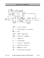
130 AMP TIG / 90 AMP
ARC WELDER
91811
ASSEMBLY AND OPERATING INSTRUCTIONS
®
3491 MISSION OAKS BLVD., CAMARILLO, CA 93011
VISIT OUR WEB SITE AT HTTP://WWW.HARBORFREIGHT.COM
Copyright © 2004 by Harbor Freight Tools®. All rights reserved. No portion of
this manual or any artwork contained herein may be reproduced in any shape or
form without the express written consent of Harbor Freight Tools.
For technical questions and replacement parts, please call 1-800-444-3353.
SPECIFICATIONS
Welding Current
DC TIG: 130 Amps; Range: 5 to 130 Amps
DC ARC: 90 Amps; Range: 5 to 90 Amps
Load Voltage
DC TIG: 15.2 Volts; DC ARC: 21.6 Volts
No-load Voltage
50
Power Consumption
220 VAC, 18 Amps, 60 Hz, single phase
Duty Cycle
35% (3-1/2 minutes ON, followed by at least 6-1/2 minutes OFF)
Material Thickness
TIG: .024” to .118”; ARC: .024” to .197”
Line Cord Length
6’ – 2” (without 220 VAC plug, not included)
Arc Torch Cable Length
9’ – 1”
Tungsten Electrode Size Capacity
1/ ”
16
Included Electrodes
5 pc., 1/16", Thoriated
Connection Type
DINS Connection, 9mm, lug with 0.160 key
Overall Dimensions
16" (L) x 15-3/4" (H) x 12-1/4" (W)
Weight
17.75 lbs.
Accessories
TIG Torch, ARC welding electrode holder, grounding clamp, gas hose,
shoulder strap, carrying handle, 2 extra collets, 5 extra nozzle covers
to 1/8”
SAVE THIS MANUAL
You will need the manual for the safety warnings and precautions, assembly instructions,
operating and maintenance procedures, parts list and diagram. Keep your invoice with this
manual. Write the invoice number on the inside of the front cover. Keep the manual and
invoice in a safe and dry place for future reference.
GENERAL SAFETY RULES
WARNING!
READ AND UNDERSTAND ALL INSTRUCTIONS. Failure to follow all instructions
listed below may result in electric shock, fire, and/or serious injury.
SAVE THESE INSTRUCTIONS
Work Area
1.
Keep your work area clean and well lit. Cluttered benches and dark areas invite
accidents.
2.
Do not operate power tools in explosive atmospheres, such as in the presence
of flammable liquids, gases, or dust. Power tools create sparks which may ignite the
dust or fumes.
3.
Keep bystanders, children, and visitors away while operating a power tool.
Distractions can cause you to lose control. Protect others in the work area from debris
such as chips and sparks. Provide barriers or shields as needed.
REV 10/04; 11/04; 09/05
SKU 91811
For technical questions, please call 1-800-444-3353.
Page 2
Electrical Safety
4.
Avoid body contact with grounded surfaces such as pipes, radiators, ranges,
and refrigerators. There is an increased risk of electric shock if your body is
grounded.
5.
Do not expose power tools to rain or wet conditions. Water entering a power tool
will increase the risk of electric shock.
6.
Grounded tools must be plugged into an outlet properly installed and grounded
in accordance with all codes and ordinances. Never remove the grounding
prong or modify the plug in any way. Do not use any adapter plugs. Check with
a qualified electrician if you are in doubt as to whether the outlet is properly
grounded. If the tools should electrically malfunction or break down, grounding
provides a low resistance path to carry electricity away from the user.
7.
Double insulated tools are equipped with a polarized plug (one blade is wider
than the other). This plug will fit in a polarized outlet only one way. If the plug
does not fit fully in the outlet, reverse the plug. If it still does not fit, contact a
qualified electrician to install a polarized outlet. Do not change the plug in any
way. Double insulation
eliminates the need for the three wire grounded power
cord and grounded power supply system.
8.
Do not abuse the Power Cord. Never use the Power Cord to carry the tools or
pull the Plug from an outlet. Keep the Power Cord away from heat, oil, sharp
edges, or moving parts. Replace damaged Power Cords immediately. Damaged
Power Cords increase the risk of electric shock.
9.
When operating a power tool outside, use an outdoor extension cord marked
“W-A” or “W”. These extension cords are rated for outdoor use, and reduce the risk of
electric shock.
Personal Safety
10.
Stay alert. Watch what you are doing, and use common sense when operating a
power tool. Do not use a power tool while tired or under the influence of drugs,
alcohol, or medication. A moment of inattention while operating power tools may
result in serious personal injury.
11.
Dress properly. Do not wear loose clothing or jewelry. Contain long hair. Keep
your hair, clothing, and gloves away from moving parts. Loose clothes, jewelry, or
long hair can be caught in moving parts.
12.
Avoid accidental starting. Be sure the Power Switch is off before plugging in.
Carrying power tools with your finger on the Power Switch, or plugging in power tools
with the Power Switch on, invites accidents.
13.
Remove adjusting keys or wrenches before turning the power tool on. A wrench
or a key that is left attached to a rotating part of the power tool may result in personal
injury.
SKU 91811
For technical questions, please call 1-800-444-3353.
Page 3
14.
Do not overreach. Keep proper footing and balance at all times. Proper footing
and balance enables better control of the power tool in unexpected situations.
15.
Use safety equipment. Always wear eye protection. Dust mask, nonskid safety
shoes, hard hat, or hearing protection must be used for appropriate conditions.
Tool Use and Care
16.
Use clamps (not included) or other practical ways to secure and support the
workpiece to a stable platform. Holding the work by hand or against your body is
unstable and may lead to loss of control.
17.
Do not force the tool. Use the correct tool for your application. The correct tool
will do the job better and safer at the rate for which it is designed.
18.
Do not use the power tool if the Power Switch does not turn it on or off. Any tool
that cannot be controlled with the Power Switch is dangerous and must be replaced.
19.
Disconnect the Power Cord Plug from the power source before making any
adjustments, changing accessories, or storing the tool. Such preventive safety
measures reduce the risk of starting the tool accidentally.
20.
Store idle tools out of reach of children and other untrained persons. Tools are
dangerous in the hands of untrained users.
21.
Maintain tools with care. Keep cutting tools sharp and clean. Properly maintained
tools with a sharp cutting edge are less likely to bind and are easier to control. Do not
use a damaged tool. Tag damaged tools “Do not use” until repaired.
22.
Check for misalignment or binding of moving parts, breakage of parts, and any
other condition that may affect the tool’s operation. If damaged, have the tool
serviced before using. Many accidents are caused by poorly maintained tools.
23.
Use only accessories that are recommended by the manufacturer for your
model. Accessories that may be suitable for one tool may become hazardous when
used on another tool.
Service
24.
Tool service must be performed only by qualified repair personnel. Service or
maintenance performed by unqualified personnel could result in a risk of injury.
25.
When servicing a tool, use only identical replacement parts. Follow instructions
in the “Inspection, Maintenance, And Cleaning” section of this manual. Use of
unauthorized parts or failure to follow maintenance instructions may create a risk of
electric shock or injury.
SKU 91811
For technical questions, please call 1-800-444-3353.
Page 4
SPECIFIC SAFETY RULES FOR THIS PRODUCT
1.
Maintain labels and nameplates on the welder. These carry important information.
If unreadable or missing, contact Harbor Freight Tools for a replacement.
2.
Maintain a safe working environment. Keep the work area well lit. Make sure there
is adequate surrounding workspace. Always keep the work area free of obstructions,
grease, oil, trash, and other debris. Do not use a power tool in areas near flammable
chemicals, dusts, and vapors. Do not use this product in a damp or wet location.
3.
Avoid unintentional starting. Make sure you are prepared to begin work before
turning on the Welder.
4.
Unplug before performing maintenance. Always unplug the Welder from its
electrical outlet before performing and inspection, maintenance, or cleaning
procedures.
5.
Never leave the Welder unattended while energized. Turn power off if you have to
leave the Welder.
6.
Maintain a safe working environment. Keep the work area well lit. Make sure there
is adequate surrounding workspace. Always keep the work area free of obstructions,
grease, oil, trash, and other debris.
7.
Prevent eye injury and burns. Wearing and using ANSI approved personal safety
clothing and safety devices reduce the risk for injury.
• Wear ANSI approved safety impact eye goggles with a welding helmet
featuring at least a number 10 shade lens rating. Any additional safety
equipment worn on the head (such as a respirator or hearing protector) must fit
properly and safely underneath the welding helmet without decreasing the helmet’s
effectiveness.
• Leather leggings, fire resistant shoes or boots should be worn when using this
product. Do not wear pants with cuffs, shirts with open pockets, or any clothing that
can catch and hold molten metal or sparks.
• Keep clothing free of grease, oil, solvents, or any flammable substances. Wear dry,
insulating gloves and protective clothing.
• Wear an approved head covering to protect the head and neck. Use aprons, cape,
sleeves, shoulder covers, and bibs designed and approved for welding and cutting
procedures.
• When welding or cutting overhead or in confined spaces, wear flame resistant ear
plugs or ear muffs to keep sparks out of ears.
8.
Prevent accidental fires. Remove any combustible material from the work area.
•
When possible, move the work to a location well away from combustible materials.
If relocation is not possible, protect the combustibles with a cover made of fire
resistant material.
SKU 91811
For technical questions, please call 1-800-444-3353.
Page 5
• Remove or make safe all combustible materials for a radius of 35 feet (10 meters)
around the work area. Use a fire resistant material to cover or block all open doorways, windows, cracks, and other openings.
• Enclose the work area with portable fire resistant screens. Protect combustible
walls, ceilings, floors, etc., from sparks and heat with fire resistant covers.
• If working on a metal wall, ceiling, etc., prevent ignition of combustibles on the other
side by moving the combustibles to a safe location. If relocation of combustibles is
not possible, designate someone to serve as a fire watch, equipped with a fire
extinguisher, during the welding process and for at least one half hour after the
welding is completed.
• Do not weld or cut on materials having a combustible coating or combustible internal structure, as in walls or ceilings, without an approved method for eliminating the
hazard.
• Do not dispose of hot slag in containers holding combustible materials. Keep a fire
extinguisher nearby and know how to use it.
• After welding or cutting, make a thorough examination for evidence of fire. Be
aware that easily visible smoke or flame may not be present for some time after the
fire has started. Do not weld or cut in atmospheres containing dangerously reactive
or flammable gases, vapors, liquids, and dust. Provide adequate ventilation in work
areas to prevent accumulation of flammable gases, vapors, and dust. Do not apply
heat to a container that has held an unknown substance or a combustible material
whose contents, when heated, can produce flammable or explosive vapors. Clean
and purge containers before applying heat. Vent closed containers, including
castings, before preheating, welding, or cutting.
9.
Avoid overexposure to fumes and gases. Always keep your head out of the fumes.
Do not breathe the fumes. Use enough ventilation or exhaust, or both, to keep fumes
and gases from your breathing zone and general area.
• Where ventilation is questionable, have a qualified technician take an air sampling
to determine the need for corrective measures. Use mechanical ventilation to
improve air quality. If engineering controls are not feasible, use an approved respirator.
• Work in a confined area only if it is well ventilated, or while wearing an air-supplied
respirator.
• Follow OSHA guidelines for Permissible Exposure Limits (PEL’s) for various fumes
and gases.
• Follow the American Conference of Governmental Industrial Hygienists recommendations for Threshold Limit Values (TLV’s) for fumes and gases.
• Have a recognized specialist in Industrial Hygiene or Environmental Services
check the operation and air quality and make recommendations for the specific
welding or cutting situation.
SKU 91811
For technical questions, please call 1-800-444-3353.
Page 6
10.
Always keep the Welding Hoses away from welding spot. Examine the Welding
Hoses for cuts, burns, or worn areas before each use. If any damaged areas are found,
replace the Welding Hoses immediately.
11.
Read and understand all instructions and safety precautions as outlined in the
manufacturer’s manual for the material you will weld.
12.
Proper cylinder care. Secure cylinders to a cart, wall, or post, to prevent them
from falling. All cylinders should be used and stored in an upright position.
Never drop or strike a cylinder. Do not use cylinders that have been dented.
Cylinder caps should be used when moving or storing cylinders. Empty cylinders
should be kept in specified areas and clearly marked “empty.”
13.
Never use oil or grease on any inlet connector, outlet connector, or cylinder
valves.
WARNING! This product, when used for welding and similar applications, contains
or produces a chemical known to the State of California to cause cancer and birth defects (or other reproductive harm). (California Health & Safety Code 25249.5 et seq.)
WARNING! The brass components of this product contain lead, a chemical known
to the State of California to cause birth defects (or other reproductive harm). (California
Health & Safety Code 25249.5 et seq.)
WARNING! Pacemaker safety warning. People with pacemakers should consult
their physician(s) before using this product. Electromagnetic fields in close proximity
to a heart pacemaker could cause interference to, or failure of the pacemaker.
SKU 91811
For technical questions, please call 1-800-444-3353.
Page 7
GROUNDING
This welder requires a 3-prong, 220 VAC, polarized, twistlock plug (not supplied). This
plug must be installed by a qualified electrician.
WARNING!
Improperly connecting the grounding wire can result in the risk of electric shock.
Check with a qualified electrician if you are in doubt as to whether the outlet is
properly grounded. Do not modify the power cord provided with the tool or
product. Never remove the grounding prong from the plug. Do not use the tool if
the power cord or plug is damaged. If damaged, have it repaired by a service
facility before use. If the plug will not fit the outlet, have a proper outlet installed by
a qualified electrician.
EXTENSION CORDS
If an extension cord is to be used with this welder, it must be rated to handle 220 VAC,
single phase at 20 amps.
1.
Grounded, 220 VAC tools require a three wire extension cord.
2.
As the distance from the supply outlet increases, you must use a heavier gauge
extension cord. Using extension cords with inadequately sized wire causes a serious
drop in voltage, resulting in loss of power and possible tool damage.
3.
The smaller the gauge number of the wire, the greater the capacity of the cord. For
example, a 14 gauge cord can carry a higher current than a 16 gauge cord.
4.
When using more than one extension cord to make up the total length, make sure
each cord contains at least the minimum wire size required.
5.
If you are using one extension cord for more than one tool, add the nameplate
amperes and use the sum to determine the required minimum cord size.
6.
If you are using an extension cord outdoors, make sure it is marked with the suffix “WA” (“W” in Canada) to indicate it is acceptable for outdoor use.
7.
Make sure your extension cord is properly wired and in good electrical condition.
Always replace a damaged extension cord or have it repaired by a qualified
electrician before using it.
8.
Protect your extension cords from sharp objects, excessive heat, and damp or wet
areas.
SKU 91811
For technical questions, please call 1-800-444-3353.
Page 8
SYMBOLOGY
Table B
UNPACKING
When unpacking, check to make sure that all the parts are included. Refer to the Assembly
section, and the Assembly Drawing and Parts List at the end of this manual.
If any parts are missing or broken, please call Harbor Freight Tools at the number on the
cover of this manual as soon as possible.
Arc Welding Electrode Holder (53)
TIG/ARC DC Welder
Grounding Clamp/Cable (54)
Collets
220 VAC
Line Cord
Nozzle Covers
TIG Torch
Accessories
TIG Torch Assembly (52)
ASSEMBLY INSTRUCTIONS
Connect a 3-prong, 220 VAC, polarized, twistlock plug (not supplied) to the Line Cord. This
plug must be installed by a qualified electrician.
SKU 91811
For technical questions, please call 1-800-444-3353.
Page 9
OPERATING INSTRUCTIONS
Controls and Indicators
Argon Gas Inlet (49) at
opposite end of unit.
Power Indicator (5)
Power Switch (3)
Welding Indicator (6)
Current Adjustment
Potentiometer (4)
Overheat Indicator (7)
Argon Gas Outlet (10)
TIG Torch or Arc Electrode
Holder - Quick Coupler (8)
Workpiece Ground
Cable Clamp Quick Coupler (8)
TIG Torch Cable Plug or Arc
Electrode Holder Cable Plug
Grounding Clamp/Cable (54)
Gas Outlet Hose
TIG Welding
Before beginning, please read and understand the section “Specific Safety Rules” as
described on pages 5, 6, and 7.
1.
Place the Welder near the workpiece to be welded.
2.
Connect a hose and coupling from the Argon gas regulator on the Argon gas tank (not
supplied) to the Argon Gas Inlet (49) at the rear of the unit.
3.
Connect the TIG Torch (52) cable plug and gas outlet
hose as shown above. Twist to lock in place.
4.
Plug in the Grounding Clamp/Cable (54) into the Ground
Cable Quick Coupler (8). Twist to lock in place.
5.
Securely place the clamping end of the Grounding
Clamp/Cable (54) to a part of the workpiece metal that is
clean of paint, oil, or dirt.
6.
Assemble the desired accessories and rod to the tip of
the TIG Torch (52) handle. Welding rod types may vary
for welding different metals.
7.
Verify that the Power Switch (3) is off, then plug the 220 VAC line cord plug into a 220
VAC, 20 amp (minimum) outlet.
8.
Turn the Current Adjustment Potentiometer (4) to the desired current. Refer to the
Specifications on page 2 for the current ranges.
9.
Open the Screw Valve on the TIG Torch handle to the desired gas flux value.
TIG Torch Handle
Screw Valve
Tip Accessories
REV 11/04; 09/05; REV 07/06
SKU 91811
For technical questions, please call 1-800-444-3353.
Page 10
10.
When everything is in place for welding, press the Power Switch to the On position.
Caution: Be careful not to touch anything else with the welding rod except the workpiece.
11.
Orient yourself on the area to be welded, then hold the Arc Shaded Face Shield over
your eyes, then strike the metal to begin welding.
Warning: Never look at the ignited arc without ANSI approved, arc shaded, eye protection in a full face shield. Permanent eye damage or blindness can occur. Skin burns can
occur. Never breath arc fumes.
Never tap the electrode wire into the welding surface to ignite the arc. This damages
its external coating on the electrode which prevents oxygen in the air from coming into
contact with the molten metal, causing it to oxidize.
12.
Once the arc is ignited, tilt the electrode wire forward at an angle of about 35°. Refer to
the illustration on the next page.
13.
When finished welding;
- slowly lift the TIG Torch handle from the workpiece,
- press the Power Switch to the Off position,
- set the TIG Torch handle down on a nonflammable and nonconductive surface,
- turn the Argon gas supply off,
- Unplug the line cord plug from the outlet.
Note: If too much current is drawn from the welder, the Thermal Overload protector will activate, the red Overload indicator will light, and the welder will turn off until it cools down. It will
automatically reset.
Arc Welding
Before beginning, please read and understand the section “Specific Safety Rules” as
described on pages 5, 6, and 7.
1.
Place the Welder near the workpiece to be welded.
2.
Connect the Arc Welding Electrode Holder (53) to the Arc Welding cable Quick
Coupler (8). Twist to lock in place. Refer to the photo of the Controls and Indicators on
the previous page.
3.
Plug in the Grounding Clamp/Cable (54) into the Ground Cable Quick Coupler (8).
Twist to lock in place.
4.
Securely place the clamping end of the Grounding Clamp/Cable (54) to a part of the
workpiece metal that is clean of paint, oil, or dirt.
5.
Place the metal portion of the welding rod inside the jaws of the Arc Welding Electrode
Holder (53). Welding rod types vary for welding different metals.
6.
Verify that the Power Switch (3) is off, then plug the 220 VAC line cord plug into a 220
VAC, 20 amp (minimum) outlet.
7.
Turn the Current Adjustment Potentiometer (4) to the desired current. Refer to the
Specifications on page 2 for the current ranges.
SKU 91811
For technical questions, please call 1-800-444-3353.
Page 11
8.
When everything is in place for welding, press the Power Switch to the On position.
Caution: Be careful not to touch anything else with the welding rod except the workpiece.
9.
Orient yourself on the area to be welded, then hold the Arc Shaded Face Shield over
your eyes. Then, strike the metal to begin welding.
Warning: Never look at the ignited arc without ANSI approved,
arc shaded, eye protection in a full face shield. Permanent
eye damage or blindness can occur. Skin burns can occur.
Never breath arc fumes.
Never tap the electrode wire into the welding surface to
ignite the arc. This damages its external coating on the
electrode which prevents oxygen in the air from coming
into contact with the molten metal, causing it to oxidize.
10.
Once the arc is ignited, tilt the electrode wire forward at an
angle of about 35°. Refer to the illustration on the next
page.
11.
When finished welding;
- slowly lift the Arc Welding Electrode Holder (53) from
the workpiece,
- press the Power Switch to the Off position,
- set the Arc Welding Electrode Holder (53) down on a nonflammable and
nonconductive surface,
- unplug the line cord plug from the outlet.
INSPECTION, MAINTENANCE, AND CLEANING
WARNING! Make sure the Power Switch of the welder is in its “OFF” position and
that the tool is unplugged from its electrical outlet before performing any inspection,
maintenance, or cleaning procedures.
1.
Before each use, inspect the general condition of the welder. Check for loose screws,
misalignment or binding of the fan, cracked or broken parts, damaged electrical wiring,
and any other condition that may affect its safe operation. If abnormal noise or
vibration occurs, have the problem corrected before further use. Do not use damaged
equipment.
2.
Periodically recheck all nuts, bolts, and screws for tightness.
3.
Periodically blow the dust from the cooling vents with compressed air.
4.
Verify that the cooling fan is operational before welding.
5.
If an odd smell comes from the unit during operation, stop all use. Have the welder
inspected and repaired by a qualified service technician.
6.
Store the welder and accessories in a clean and dry location.
SKU 91811
For technical questions, please call 1-800-444-3353.
Page 12
7.
Periodically clean out the TIG Torch Head by unscrewing its components and cleaning
with a brush.
PARTS LIST
NOTE: Some parts are listed and shown for illustration purposes only and are not available individually
as replacement parts.
PLEASE READ THE FOLLOWING CAREFULLY
THE MANUFACTURER AND/OR DISTRIBUTOR HAS PROVIDED THE PARTS DIAGRAM IN THIS
MANUAL AS A REFERENCE TOOL ONLY. NEITHER THE MANUFACTURER NOR DISTRIBUTOR MAKES
ANY REPRESENTATION OR WARRANTY OF ANY KIND TO THE BUYER THAT HE OR SHE IS QUALIFIED
TO MAKE ANY REPAIRS TO THE PRODUCT OR THAT HE OR SHE IS QUALIFIED TO REPLACE ANY
PARTS OF THE PRODUCT. IN FACT, THE MANUFACTURER AND/OR DISTRIBUTOR EXPRESSLY STATES
THAT ALL REPAIRS AND PARTS REPLACEMENTS SHOULD BE UNDERTAKEN BY CERTIFIED AND LICENSED TECHNICIANS AND NOT BY THE BUYER. THE BUYER ASSUMES ALL RISK AND LIABILITY
ARISING OUT OF HIS OR HER REPAIRS TO THE ORIGINAL PRODUCT OR REPLACEMENT PARTS
THERETO, OR ARISING OUT OF HIS OR HER INSTALLATION OF REPLACEMENT PARTS THERETO.
SKU 91811
For technical questions, please call 1-800-444-3353.
Page 13
ASSEMBLY DRAWING
55
SKU 91811
56
57
For technical questions, please call 1-800-444-3353.
58
Page 14
ELECTRICAL SCHEMATIC
SKU 91811
For technical questions, please call 1-800-444-3353.
Page 15