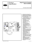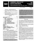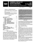
1
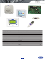
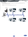
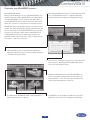
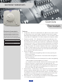
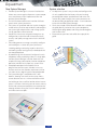
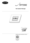
Controls Index System architecture 164 Index Type Building management system Fan coil controllers Hydronic systems Zoning systems Chilled-water plant control system Range Page Carrier Comfort Network (CCN) Comfort-View 166 168 Electronic thermostats Overview HDB controllers NTC controllers 170 171 172 174 Aquasmart Evolution 176 VVT (33CZ) Comfort Zone II 180 182 Pro-Dialog CSM III 184 186 165 carrier comfort network Controls CCN Network options • Cover the essential elements of a Building Management System providing diverse facilities such as remote monitoring, collection of performance data, maintenance management and customized reporting capabilities. • Performed through individual programs that can be added to the Carrier Comfort Network via individual modules which provide a diverse set of system facilities. • The following network options are available: - Data Collection - Network Bridge - Network Directory Services - Network Repeater NAM - TeLink analogue modem for remote connection Features • The most advanced technology resulting from Carrier’s thorough knowledge of both comfort and controls. It offers the owner, designer and installer: - integrated product and control systems - single-point responsibility - unique control strategies - overall lower installation costs - enhanced monitoring capabilities • Whilst each equipment component can operate in a stand-alone mode, all components form a fully-integrated and balanced HVAC system when networked with other Carrier equipment through the Carrier Comfort Network. A three-wire cable is all that is required to connect these products. ComfortView • Powerful supervision software package that allows centralised monitoring (local and remote), data collection, report generation and system configuration. • Designed to run on most PCs running on Windows 2000 or Windows XP. • Designed for larger scale building management needs with custom graphical representation. Product-integrated controller • Factory-installed product with a level of monitoring and diagnostic control that can only be achieved with a factory-integrated device. • Product-Integrated Controllers are available on chillers, rooftops, air handling units and terminal fan coil units. Comfort controller • Field-installed device which allows non-Carrier equipment such as boilers, cooling towers and pumps to be controlled and integrated into the overall network. • Fully programmable to suit the application need and optimized control strategies. 166 CCN System Managers • Carrier offers a complete line of network system products that tie multiple stand-alone products together for a fully integrated, self-adjusting HVAC system: Example: Chillervisor System Manager (CSM III) for chiller plant control CSM III Chiller System Manager CCN protocol ComfortView Supervision 167 comfortview iii Controls ComfortVIEW Can perform the following tasks: • Display dynamic data in text and graphic modes • Create dynamic trend plots of data from one or multiple controllers • View, print, and acknowledge alarms from the network • Configure operating parameters such as time schedules, set-points, and point configuration • View and configure time and setpoint schedules in graphic and text mode • Download and upload data to and from controllers • Override the state or value of selected input and output points • Customise graphics and create custom links between graphics • Generate reports from system data/ operator activity • Create custom WorkSPACEs for each user • Easily backup all database information to disk • Obtain on-line operator help • Custom programming (BEST++) Features • The primary human interface to the Carrier Comfort Network (CCN). • Designed to run on any PC utilising the Microsoft“ Windows 2000 Professional or Server operating system, or the Windows XP Professional operating system. • True system multitasking. • Local Area Network - allows multiple workstations to share a common system database. • Remote Communications - allows access to remote ComfortVIEW databases. • Graphical User Interface (GUI) - provides a consistent look and intuitive operation. • Customised Access Levels. • Export data into other application software. • Dynamic Data Exchange (DDE). • Time and set-point schedule DLL allows third parties access to CCN time and set-point schedules. • CCN to Ethernet support provides for flexible location of the ComfortVIEW computer. • Organise and view data in a convenient format and to create your own custom data displays. • Alarm processing is the automatic and full-time responsibility of ComfortVIEW. Receives, announces, and stores prioritised alarms. • The Carrier Network Manager allows you to display, modify, and delete the areas, controllers, and data tables in your ComfortVIEW database. • The Reports function is used to generate reports from network and database data. • ComfortVIEW report data also allows you to create your own custom reports. 168 ComfortVIEW III Customise your WorkSPACE screens... View critical data at once Because no two buildings are alike, ComfortVIEW offers the flexibility to create custom WorkSPACES, each comprised of multiple ViewSPACES, such as graphics and tables. With a custom WorkSPACE, you can see all the critical information about your system on a single screen. For example, create a WorkSPACE screen with graphics of your main chiller and air handler, plus tables showing key operating data for each one. You can then save the finished WorkSPACE so it is available to access time and again. Multi-element WorkSPACES are troubleshooting time-savers, allowing you to adjust the operation of one unit and see how it affects another part of the system ... all on the same screen. • With ComfortVIEW you can get the information you need fast. Link WorkSPACE screens in a logical progression customised for your building and management needs. • ComfortVIEW lets you see your building’s equipment operation and easily access time and set-point schedules – without leaving your office. • With real time trend scanning, you can visually determine how a system is behaving. ComfortVIEW allows you to easily view and record this data. • Reduce troubleshooting time with ComfortVIEW’s onscreen interaction. Change temperature set-points, or force conditions – then view the results and determine action, prior to dispatching a mechanic. • This power plant ViewSPACE shows various equipment operating parameters at a glance. • ViewSPACES can use graphics or photos of your actual equipment, for easier analysis of operating conditions. 169 electronic thermostats Controls Thermostats Electronic thermostats: The Carrier electronic thermostats are designed to control and optimise the operation of hydronic terminal fan coil units. They exist in two versions that match all terminal fan coil configurations: 2-pipe 2-pipe changeover 2-pipe and electric heater 2-pipe changeover and electric heater 4-pipe Type A x x Type B x x x Features • Fan operation - With the fan speed selector, fan mode can be set either manually or automatically. In the manual mode it is possible to select three fan speeds (low/medium/high) according to personal preference. In the auto mode fan speed is regulated by a microprocessor in the control, based to the temperature chosen. • Temperature selector - This is designed to maintain the temperature at the desired level. The reference value at the centre of the range is 20°C. By turning the knob towards the symbol (-) the temperature is reduced from the original setting (minimum value is 10°C). By turning the knob towards the symbol (+), the temperature is raised from the original setting (maximum value is 30°C). • Energy saving mode - This function is especially useful when air conditioning at night or in rooms where the user is likely to be absent for a longer period of time. In this case, pushing the button raises the temperature during cooling by 4°C and lowers it during heating by 4°C. • Seasonal changeover - Manual - Selection of heating/cooling is done manually by pushing the button on the control. - Centralised (only for type A control) - Centralised seasonal changeover is possible in two ways: -by a switch located on the central control panel that allows heating/cooling mode changeover (to be provided by the installer). -by a temperature sensor located in contact with the entering water pipe - Automatic, based on air temperature (only for type B control) - The automatic seasonal changeover allows automatic switching of the fan coil operating mode to cooling or heating, depending on the temperature set by the user and on the room temperature. • External contact - The control has a 230 V input that can be used as window contact or presence detector. When such a signal is activated (presence of line voltage on the terminal block contact) the control is set to OFF mode. As a consequence, all outputs (fan, valves etc.) are disconnected, and only frost protection is active, if switched ON by the appropriate dip-switch. • Frost-protection - This function keeps the temperature from dropping below 7°C in rooms not used for long periods of time. 170 Electronic controllers Electronic fan coil controllers - quick reference table Control algorithms On-off Proportional-integral Valve management Air flow control only (no valve) On-off actuators Proportional valves Fan control Three speeds Optimum fan speed selection Variable speed Main functions Setpoint control Occupied/unoccupied mode Frost protection mode Window contact input Measurement of water inlet temperature for automatic seasonal changeover (2 pipes) Automatic seasonal changeover (4 pipes and 2 pipes + electric heater) Manual changeover Frost protection mode Continuous ventilation within dead-band Periodical ventilation within dead-band Unit grouping Louvre control On-site configuration Supply air temperature monitoring limiting Communication (CCN) Electrical heater loadshed Dirty filter alarm Alarm reporting IAQ control Demand control ventilation (DCV) Free cooling mode User interface Digital display Automatic or manual fan speed control Operating mode selection Occupancy (eco) button Thermostats HDB x x NTC x x x x x x x x x x x o x x x x Type A Type B x x x x x x x x x x x x x x x x x x x x x x x x x x x x x x x x x x x o o o x x x x x x x x x x x 171 x o HDB controller Controls HDB User interfaces Depending on the application, two user interface types can be selected: • a wired user interface that can be mounted on the wall or inside compatible terminal fan coils (42N) • an infrared user interface to be used together with a wall-mounted infrared received or a receiver incorporated in compatible terminal fan coils (42GW) Features • The HDB controller is a microprocessor-based controller designed to control and optimise the operation of hydronic terminal fan coil units. • Factory-installed on the terminal fan coil - The controller is factory-installed on the terminal fan coil; the assembly is also tested at the factory. As a result, field installation is extremely simple. • Ease of grouping - As an option, the HDB control can be equipped with a grouping board that is used to connect up to 15 units with a bus. All units connected together will operate under the same conditions. • Louvre control - For terminal fan coils equipped with motorised louvres, the HDB controls the louvre position as defined by the user or in swing mode. • External contact - The control has an input that can be used to remotely set the unit to economy mode. • Scheduling - If the unit is used with an infrared user interface, unit operation time can be scheduled on a daily basis. Three start times and three stop times can be programmed. • Timer - If the unit is used with an infrared user interface it can operate for a predefined duration before switching to eco mode or off. 172 HDB controller 56 Carrier Room Conroller (CRC2( 250 Infrared Remote Control (IR2) and receiver 190 173 HYDRONIC FAN COIL COMMUNICATING CONTROLLER (NTC) Controls NTC Network communication Description • The NTC communicating controller can be connected on an RS 485 bus, using the Carrier Comfort Network (CCN) protocol. • Units equipped with the NTC controller can be part of the Aquasmart Evolution system. Carrier offers one of the market’s most sophisticated and complete communicating controllers for hydronic fan coil ranges, the NTC controller, that is compatible with the full Carrier fan coil range. For the customer and installer the same controller simplifies and eases installation and service operations whilst covering a wide range of hydronic system types and applications. The controller can be applied and function as either a standalone control, as part of a larger CCN system application, or at the heart of a Aquasmart system functioning with the Aquasmart Touch Pilot System Manager. Advanced functions • Low Energy Consumption (LEC) variable speed control. • The NTC controller can drive the fan speed continuously within a configurable range for optimal thermal and acoustic comfort. • Hydronic control - The NTC controls both floating and fixedpoint value actuator types (230 V on-off and 230 V three point). • Demand controller ventilation (DCV) - On fan coils equipped with CO2 sensors and fresh air dampers, the NTC controller can adjust the amount of fresh air admitted to the room, as required by the occupants. • IAQ management - The NTC controller can control all features related to Indoor Air Quality that are included in Carrier terminal fan coil units. Features • The NTC controller controls and optimises the operation of hydronic terminal fan coil units. It is a microprocessor-based CCN (Carrier Comfort Network) compatible communicating controller with energy-saving algorithms. • Energy-saving algorithms manage water valve operation and fan speed control simultaneously to ensure minimum energy consumption whilst maximising comfort conditions for the occupant. • Factory-installed on terminal fan coils The NTC controller is factory-installed on the terminal fan coil; the assembly is also factory-tested. As a result, field installation is extremely simple. • A wide range of user interfaces Depending on the application, two user interface types can be selected: - a simplified wired analogue user interface (SUI) that can be wall-mounted - a wired communicating user interface (CRC2) that can be wall-mounted or incorporated in compatible terminal fan coils (42N) - an infrared user interface (IR2) for use together with a wall-mounted infrared received or a receiver incorporated on compatible terminal fan coils (42GW) - a multi-function user interface (ZUI) that can control comfort, lights and blinds within a Carrier system 174 NTC controller 56 Carrier Room Conroller (CRC2( Simplified User Interface (SUI) 250 Zone User Interface (ZUI) Infrared Remote Control (IR2) and receiver 190 2 1 1 3 1 3 4a 4b 1 1 3 5 6 A Legend 1 NTC controller 2 Secondary communication bus 3 User interface connection 4 IR2 5 ZUI2 6 CRC2 A Room A B Room B 175 B AQUASMART EVOLUTION FEATURING THE NEW SYSTEM MANAGER FOR THE AQUASMART SYSTEM Controls Aquasmart Description Features • Aquasmart Evolution is a complete heating, ventilating and air conditioning (HVAC) system, ideal for residential and light commercial office buildings, hotels and hospitals. It offers perfect comfort for the building occupants. • An Aquasmart system can consist of up to 128 terminal fan coil units, served by one or more chillers or heat pumps, that supply cooling and/or heating to occupied spaces. Typically hydronic systems include fresh air handling units supplying pre-treated outside ventilation air via the fan coil units or directly into the occupied space. The Aquasmart system can contain up to eight such units. • The Aquasmart Evolution system ensures significant energy savings combined with optimised user comfort by managing building zoning, occupancy and room temperatures in accordance with needs. • Terminal fan coil units can be organised in up to 32 zones to optimise building management by zone requirements and dependent on building design conditions. Requirements can cover applications of up to 2500 m². • The Touch Pilot System Manager – the brain and human interface – was redesigned to facilate use and allow rapid access to manage and configure building operation and maximise energy savings at comfort conditions. • All system components are fitted with communicating controls to manage local user comfort needs whilst allowing the System Manager to communicate with the system components and to obtain feedback on user needs. Based on the individual fan coil unit requirements the System Manager coordinates the system heating and cooling modes for maximum comfort and optimal energy consumption, respecting the comfort parameters and occupancy schedules for the building zones. • The Touch Pilot System Manager and associated controls offer an affordable building management system with many functions that are usually only available in more expensive solutions and require additional building by building programming development. 176 Aquasmart System design layout and configuration guide Energy savings • The System Manager is connected to the system components via a communication bus, and allows control of all system and individual terminal operating parameters. • System configuration is simple through easily accessible menus. Unit grouping is managed by the network and requires no specific wiring. This means the system can be easily reconfigured to suit later modifications to the occupied area. • The Aquasmart Evolution components are delivered complete, configured and factory-tested. • The Aquasmart system offers superior comfort levels and by optimising and controlling the system components allows building owners and occupants to save energy and reduce their energy bill, contributing to a reduction in carbon emissions from building HVAC systems. • Energy simulations conducted with a recognised software simulation program indicate that it is possible to achieve energy savings of up to 25% over a traditional non-communicating and non-optimised system. • Further significant energy savings are attainable by incorporating the 39SQ “plug & play” fresh air handling unit with heat recovery technology and considering the use of 30RQ air-to-water heat pumps for space heating, and 61AF heat pumps for domestic hot water. Each project merits its own assessment of the opportunities. 177 Aquasmart New System Manager System selection • The New System Manager is a human interface that allows users to manage the Aquasmart system components and features major improvements over the previous System Manager. • An intuitive colour touch screen interface facilitates access to the system parameters. • The system set-up wizard leads the installer through a number of easy intuitive steps to identify and configure the system type and parameters and manage system set-up, operation and maintenance. • Icon-driven menus ease navigation through set-up, configuration, and service and maintenance menus to easily and rapidly manage and maintain the HVAC system. • The building owner or manager can quickly configure and reconfigure a number of system parameters including cooling and heating set points (terminals and cooling and/or heating plants) and occupied and non-occupied periods. • By coordinating with the control intelligence in each component and by assembling all data at a single point, the New System Manager interface allows the user to optimise energy consumption, monitor component operation and continually report any system faults. • Occupied/unoccupied time schedules can be programmed, and the system includes smart start features to ensure that comfort requirements will be met from the very beginning of the occupied period. • The System Manager is compatible with a web browser, allowing user access to the system from a remote location such as a maintenance office within the building or from an offsite location where internet access is available -facilitating ease-of-access and use; Service and maintenance companies can extend service coverage without visiting the site, thus reducing carbon emissions due to transport. • An Aquasmart system is easy to select and configure with all units supplied from the factory with pre-installed, pre-configured and pre-tested controls and valves. The installer only needs to adjust the system parameters to the local building or application needs - a task made even easier with the New System Manager. • Carrier has created a Quick Selection Guide that is available to rapidly identify and select the system components, facilitating the design process and saving time for designers and installers alike. • Please contact your local sales office for a copy of this guide. 178 Aquasmart New features for 2011 • The Touch Pilot System Manager can now manage up to eight fresh air handling units as part of the system. • The air treatment units (39SQ) supplied by Carrier are equipped with CCN controllers, they are fully integrated into the system and managed by the Aquasmart System Manager. Each fresh air plant can be associated with specific terminal fan coils and/or zones for optimum management of building use with occupancy, controlling and minimising energy use. Individual schedules can be set up and managed for each and all air treatment plants. • The Aquasmart System Manager supplies building information enabling dynamic and precise control of the 39SQ’s night-time free-cooling feature to further reduce building energy consumption. • If the air treatment units are not supplied by Carrier, integration is limited to control via a digital output for the main fresh air unit. • The Touch Pilot System Manager offers two possibilities to link to an external building management system, if there is an alarm signal from the system. The first possibility is to use one of the digital outputs to provide an external signal to be linked by the building integrator as required, and the second offers users of a Carrier ComfortView building management system the capability to access and read an alarm point. Specific alarm messages will then be available through the System Manager interface. 7 1 Legend: BP Primary bus BS Secondary bus 1 New System Manager (NSM) 2 Pro-Dialog+ interface 3 Boiler 4 5 6 7 6 Carrier chiller/heat pump Air handling unit Ethernet connection Web browser 179 3V PACKAGED CONTROL SYSTEM Controls 33CZ Accessories • Remote room sensors (with or without LCD display) • Wall- our duct-mounted CO2 sensor to monitor indoor air quality levels • ComfortView software provides onsite or remote monitoring facility • Outdoor-air sensor (HH79NZ039) reports the outdoor-air temperature to the communication bus. The information can be used to lock out heating or cooling modes when the temperature is not within userconfigured limits. The outdoor-air sensor is needed when an economizer is used. • Supply air temperature sensor (33ZCSENSAT) is required for heating applications or stand-alone operation. • Duct temperature sensor (33ZCSENDAT) is required for use with a bypass controller and must be installed in the supply air duct. Additional control features • The VVT zoning system components provide additional control features such as occupied/unoccupied scheduling initialised via the network. The VVT zone controller offers override invoked from a wall sensor during unoccupied hours from 1 to 1440 minutes in 1-minute increments. Optional Indoor Air Quality (IAQ) control or relative humidity monitoring are also available. Features • User interface - The VVT zoning system is designed to allow a service person or building owner to configure and operate the VVT bypass controller and zone controllers, a linkage-compatible air source and all other networked devices through the system pilot user interface. The System Pilot’s backlit, alphanumerical Liquid Crystal Display (LCD) and rotary knob design allow the user to navigate through the menus, select desired options and modify data with ease. All VVT zoning system maintenance, configuration, setup and diagnostic information is available through the Level II communications port to allow data access by the System Pilot or an attached computer running the ComfortVIEWTM software. • Flexibility for every application - The system maintains precise temperature control in the space by regulating the flow of conditioned air into the space using the zone and bypass controllers. Buildings with diverse load conditions can be supported by controlling reheat applications, including two-position hot water, modulating hot water, up to 3-stage electric heat or combination baseboard and ducted heat. The VVT zoning system offers zone level flexibility with its expanded range of compatible zone sensors - including simple space temperature sensors up to fully network compatible devices. • Linkage system compatibility - Linked to a Carrier linkage system, the VVT zoning system components provide numerous features and benefits such as weighted average demand for system operation, intelligent supply air temperature reset, set point averaging, global set point schedule, and occupancy scheduling. Duct static reset for the air source is provided, based on terminal requirements. • Simple actuator connection - The VVT zone controller control assembly contains an integral actuator assembly, field mounted to the VVT terminal damper shaft, similar to the mounting of a standard actuator. The VVT zone controller is designed for vertical or horizontal mounting. • Ease of installation - The VVT zoning system components are provided with removable connectors for power and communications. Non-removable screw type connectors are used for inputs. The removable connectors are designed so that they can be inserted one way to prevent installation errors. The VVT zone controller also provides an RJ-14 modular phone jack for the Network Service tool connection to the module via the Carrier communicating network. 180 33CZ 3V Bypass damper – opens to maintain minimum air flow through the constant volume unit and regulates static pressure as zone dampers close. Unit controllers System Pilot Bypass control Universal controller Zone damper – controls air flow. The damper position is modulated for precision control of space temperature. Sensor flexibility Zone damper and controller Bypass controller - compensates for changes in supply air duct static and responds by varying the amount of air flow into the return air duct or ceiling plenum. Includes an integrated modulating actuator. System Pilot - serves as the user-interface and configuration tool for the 3V zoning system. Additionally, the System Pilot can serve as a wall-mounted temperature sensor for space temperature measurement. The occupants can use the System Pilot to change set points and make occupancy overrides. A security feature is provided to regulate access to features for authorised users. Supply air sensor Carrier communicating RTU Communication bus, shielded cable (see notes 1, 2) (Use PremierLink backlit control for non-Carrier communicating RTU) 120 V ac (See note 2) 24 V ac 24 V ac 40 VA 40 VA Duct sensor (locate upstream of sensor) Shielded cable (see note 2) System Pilot (see note 6) Zone controller - communicates data, including zone-level requirements, occupancy, set points, overrides and diagnostic information to the zone controller in charge of system coordination. Includes an integrated modulating actuator. Bypass Comm Bus Legend CCN Carrier Comfort Network DCV Demand Controlled Ventilation PAT Primary Air Temperature Sensor RTU Rooftop unit VVT Variable volume/variable temperature 24 V ac 40 VA 24 V ac 40 VA Primary air sensor 24 V ac 40 VA (See note 5) VVT linkage coordinator (optional for linkage coordinator) VVT Zone Shielded cable (see note 2) T55/56/59 VVT Zone Comm Bus T55/56/59 T55/56/59 CO2/T55/56 (optional for DCV) (see notes 2,4) 181 Universal controller – used for integration of auxiliary building control such as lighting, fans, pumps, boilers and other HVAC equipment. Notes 1 239 devices maximum per bus. Repeater required every 300 m or 60 devices. Maximum of three repeaters per bus. 2. Communication bus and sensor wiring must be separate from AC power wiring. 3. Up to 32 total zones per system. Maximum of five linkage coordinators with a total of 128 devices per single bus. 4. Combination CO2/T55/T56 sensor may be used in place of T55/T56/T59 on any zone requiring DCV. RTU must be capable of controlling economizer for DCV conditions. 5. Locate PAT in supply air duct from air source unit 6. System Pilot can share power with bypass 22 zones max. controller or VVT zone controller. including linkage coordinator comfort zone II system Controls Comfort Zone II Optional system enhancements • • • • • • • Programmable controller Alarm indicators Carrier command centre software Mechanical ventilation Multiple zone dampers Smart sensors Electronic air cleaners and central humidifiers • Humidity control and display • Outside air temperature display Features • A zoning system providing owners of small commercial buildings with a practical way to manage energy and equipment operating costs while providing extremely high levels of comfort. • Centralised heating and cooling control while providing personalised comfort. • Comfort Zone II brings individual temperature and time control without the prohibitively high cost of multiple heat ing and cooling units. • Energy and operating cost savings, in addition to lower initial cost. • Easily programmed to suit specific requirements - building occupants can virtually customise the indoor climate to their individual comfort preferences and changing schedules. • Divides the building into as many as eight independent comfort zones, based on their different heating and cooling requirements and hours of use. Using a network of electronic thermostats, sensors and strategically placed, electronicallycontrolled dampers, Comfort Zone II maintains a comfortable environment in every zone. 182 Comfort Zone II Zone 1 Zone 2 Zone 4 Zone 5 Zone 3 Zone 6 Zone 8 Zone 7 1 2 Room temperature sensor 3 Zone damper or bypass damper 4 Linear air diffusor Central control board 5 Main thermostat Other distinctive features • No batteries are required • System diagnostic display • Time Guard to protect HVAC equipment from rapid cycling and minimum ON time feature • Full system communications • Barometric or motorised bypass dampers • Temperature trend staging reduces operating cost • Backlit display • Seven-day programme scheduling (four periods a day, 15-minute increments) • • • • • • ‘Droopless’ temperature set-point control Automatic changeover Clean filter alert message Copy feature (copy zone, copy previous period etc.) OFF feature (any zone can be turned completely off) ALL feature (all zones controlled to same desired temperature) • OUT feature (zone control to relaxed set-points) • Equipment protection features (Time Guards, minimum ON time, cycle timers) 183 Pro-dialog CONTROL Controls Pro-Dialog Operator interfaces Control features (Pro-Dialog Plus/Pro-Dialog touch screen) • Clear and easy to use operator interfaces • Pro-Dialog Plus interface Organisation of information around 10 menus directly accessible through hard keys • Pro-Dialog touch screen interface Organisation of information around 12 menus directly accessible through soft keys and possibility to install the touch screen remotely from the chiller • Pro-Dialog+ screen interface • An advanced numeric control system, combining complex intelligence with great operating simplicity. • Constantly monitors all machines parameters and safety devices and precisely manages the operation of compressors, fans and water pump. • PID control algorithm anticipates load variations, guarantees leaving water temperature stability and prevents unnecessary compressor cycling. • The long stroke electronic expansion valves (EXV) and PID superheat control, together with the head pressure control algorithm, improve energy efficiency at part load conditions and optimise unit operation. • Automatic reset of the chilled-water temperature set point for optimised power consumption. • Several capacity loading possibilities for improved start-up at low outdoor temperature and use of one refrigerant circuit as back-up. • Provides preventive protection and enhanced unit reliability. • Equalisation of operating time and number of compressor start-ups. • Monitors all safety parameters. Fault history function and 80 fault code for immediate fault location. • Parallel control of two units as standard. • Extensive remote control capabilities allow integration into building management systems. • RS-485 serial port for connection to the Carrier Comfort Network and any other monitoring system (through gateways). Pro-Dialog Plus interface Pro-Dialog touch screen interface - optional according to range (30XA, 30XW) 184 Pro-Dialog Pro-Dialog+ screen interface Integrated features • Pro-Dialog+ combines intelligence with operating simplicity. The control constantly monitors all machine parameters and precisely manages the operation of compressors, expansion devices, fans and of the water heat exchanger water pump for optimum energy efficiency. • Night mode: capacity and fan speed limitation for reduced noise level. • With hydronic module: water pressure display and water flow rate calculation. Ease-of-use • The new backlighted LCD interface includes a manual control potentiometer to ensure legibility under any lighting conditions. • The information is displayed clearly in English, French, German, Italian and Spanish (for other languages please consult Carrier). • The Pro-Dialog+ navigation uses intuitive treestructure menus, similar to the Internet navigators. They are user-friendly and permit quick access to the principal opera-ting parameters: number of compressors operating, suction/discharge pressure, compressor operating hours, set point, air temperature, entering/leaving water temperature. Energy management • Seven-day internal time schedule clock: permits unit on/off control and operation at a second set point. • Set point reset based on the outside air temperature or the return water temperature or on the water heat exchanger delta T. • Master/slave control of two units operating in parallel with operating time equalisation and automatic changeover in case of a unit fault (accessory). • Change-over based on the outside air temperature. Pro-Dialog+ interface 185 chillervisor system manager iii Controls CSM III Control functions: • Automatic chiller start/stop • Two seasonal chiller start/stop sequencing modes with add/drop capability • Designated standby chiller support • Occupancy-based plant operation with configuration override • Soft loading • Load balancing • Bypass valve control • Chilled water set-point reset • Loadshed demand limiting • Chiller fault handling and capacity matching • System alarm messages and alarm history • Short- and long-term power failure recovery Features • A key component of the Carrier Comfort Network (CCN) Chillervisor System. • Provides sophisticated multiple chiller control functions to optimise the efficiency of the Carrier chiller plant. • Coordinates the operation of a chilled water system in which up to eight chillers feed a common chilled water loop. • Consists of a module equipped with input and output points and specialised control and communication software. • The CSM III operator interface is ComfortWORKS, Building Supervisor III or a Network Service Tool. With this an operator can: - display a list of CSM III points that show the status of the chiller system - modify the value or status of selected points and then return them to automatic control - display and modify configuration and service data - display maintenance data - display chiller system graphics (ComfortWORKS or Building Supervisor) • Additional capabilities possible by combining the CSM III with the following CCN products: - Autodial Gateway - Remote CCN Service Interface (RCSI) - Data Collection Option - Comfort Controller - Water System Manager (WSM) - Loadshed Option - Alarm Printer Interface Module (APIM) 186 CSM III Technical data Power requirements Operating temperature Storage temperature Operating humidity 50 VA @ 24 V ac ± 15% 0°C to 60°C -40°C to 85°C 0 to 90%, non-condensing Dimensions, mm 330 70 140 187