1
US 20040181328A1
(19) United States
(12) Patent Application Publication (10) Pub. No.: US 2004/0181328 A1
(43) Pub. Date:
Davidson et al.
Sep. 16, 2004
Related US. Application Data
(54) VEHICLE IDENTIFICATION MEANS
DETECTION AND EVASION SYSTEM
(60) Provisional application No. 60/404,450, ?led on Aug.
19, 2002.
(76)
Inventors: Ron Yaacov Davidson, Zichron Yaacov
(IL); Nathaniel Davidson, Tel Aviv
(IL); Naum Lauenburg, Zoran (IL)
Correspondence Address:
WILMER CUTLER PICKERING HALE AND
DORR LLP
300 PARK AVENUE
NEW YORK, NY 10022 (US)
Publication Classi?cation
(51)
Int. Cl? ................................................... ..G01C 21/26
(52)
Us. 01. ............................... .. 701/36; 701/1; 701/213
(57)
ABSTRACT
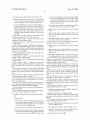
A system for detecting and evading vehicle identi?cation
means (VIM), comprising: locating means, control means
having a plurality of I/O channels, each adapted to receive
or transmit serial or parallel data, processing means, elec
tronic storage means comprising at least one database of
(21) Appl. No.:
10/640,703
knoWn VIM coordinates and identi?cation prevention
(22)
Aug. 13, 2003
of the vehicle’s license plate number, oWner or driver.
Filed:
10%
2o-\
22 ~\
24\\
device (IPD) adapted to automatically prevent identi?cation
I ______________________________________________ __|
cps
Antenna
i
:
i
28
g
/
< 7
i 31
cps
5
Receiver
:
25m
1
accuracy
i
it
i
DGPS
10m
accuracy
4 t
Embedded
i
:
System
i
With OS
%
1
database
i
1
LCD /// 16
i
Display
:
E
32
1
5
i
i
13
12
Switch Controller
18
A
/
i
I
a
l
Peripheral
\
29
14
:
_
‘PD
____—|
Patent Application Publication Sep. 16, 2004 Sheet 1 0f 10
3.
US 2004/0181328 Al
On:
m
2
.
2
\
“
mmm
m
mo.5;
0m2.58%
2."00-\ \
>m235
mu
\\Wc3:o9t5:g0w
/
U"mumEuonEw
Eur-aton
i
wm/u
you
hoz wm 593c wmO E2. 52:03
AW wmw/ Emu
INN
MW
Patent Application Publication Sep. 16, 2004 Sheet 2 0f 10
US 2004/0181328 A1
32
\
140
\
PDA Interface
AUDIO
5 volt
/1 5°
CODEC
R5232
110
USB
16{
0
H
_ L»
9.5.’
F
RS232
"""""" '"> um; DRIVER
m
1
500
100
Serial
\
ag
12o
BUS
l/ H
130
U55 T’ % c
HUB '
Power 1'
(5 VOlt/
3, '6
—-> 5
12V0lt) Power
—> SUPP'Y
33‘,
=i
SWITCH CONTROL LOGIC
Clk 530
1 /
<—
540
Clk
2 /
.
110
/
H
A
C.
:s
sm
A
:
-
w 6
11
1 1: — Q N
gm
2' g
RS232 /\ R5223
9'
1
“.ne
Line
Dnver
Driver
/7
Custom Function
Custom RS232
Interface
Interface
21
14
\
.
/
29
v
FIG. 2
19
/
Patent Application Publication Sep. 16, 2004 Sheet 3 0f 10
US 2004/0181328 A1
200
lnit all Outputs:
Connect PDA to GPS,
Turn Off all Discretes
210
ait for new Data
from PDA
230
/
22o
Bypass RS232
Data to current
User
' ight Passwor
from PDA
240
RS232 Mux
ata for RS232 Mux or
Discrete Control
I iscrete Control or USB
Turn On/Off
Move RS232
Discrete
M‘gégzigsw
according to
PDA command
FIG. 3
Patent Application Publication Sep. 16, 2004 Sheet 4 0f 10
US 2004/0181328 A1
200
lnit all Outputs:
Connect PDA to GPS,
Turn Off all Discretes
310
Bypass RS232
Transmit Data from
current User
ait for “Request to Send
signal from Custom RS232
Client
320
Identify Client Channel
Number
l
330
Wait for the Transmit
Channel Free
340
Move RS232 Mux
to Client Channel
Position
350
Enable the "Clear
to Send" signal
for Channel
FIG. 4
Patent Application Publication Sep. 16, 2004 Sheet 5 0f 10
US 2004/0181328 A1
34
l
Fault
Alarm
‘
Init T st
36
+
/
GPS Connection Test
No
GPS is OK
Yes
38
Get Current GPS
Position
28
1
44
Ill
Compare with
Speedtrap Database
Speedtrap
Database
42
Is vehicle
ls vehicle past
approaching
speedtrap?
speedtrap
.- etection area?
50
ls device
enabled?
Yes
Is device
disabled?
No
No
52
48
l
Enable
/
Disable
counter
counter
measure
device
m asur
d vic
FIG. 5
Patent Application Publication Sep. 16, 2004 Sheet 6 0f 10
38
Compar
\ Get current
GPS
current
US 2004/0181328 A1
/54
—> co rdinate
coordinate
56
Get sequence /
Yes
to database
N°
of coordinates
I
to speedtrap
‘J
58
Get (next) /
60
Compare
current
GPS
64
cur-rent
_
\
coordlnate to
coordlnate
Delete
sequence
database
A
A
Yes
Is next database
coordinate also in
66
quence coordina -
Is the speedtrap
opperating in the
direction of drivin -
68
Yes
Mark all passed
coordinates in
sequence
No
there a 60% hi
ratio
To FIG. 6B
FIG. 6A
N0
Patent Application Publication Sep. 16, 2004 Sheet 7 0f 10
US 2004/0181328 A1
72
/
70
.
/
Get current
Enable
GPS
<—— peripheral
coordinate
function
74
Has vehicle
reached
speed-trap?
Yes
76
Get current
‘ GPS
coordinate
,8
l
Calculate
distance from
speedtrap
Yes
- lstance from spee
trap > 1km
80
Disable
peripheral
function
FIG. 68
Return to
Start
-
From FIG.
6A
Patent Application Publication Sep. 16, 2004 Sheet 8 0f 10
US 2004/0181328 A1
410
420
FIG.
7
424
Patent Application Publication Sep. 16, 2004 Sheet 9 0f 10
vmw
onw
US 2004/0181328 A1
omw
vvv
O
mmv
Patent Application Publication Sep. 16, 2004 Sheet 10 0f 10
m3.
US 2004/0181328 A1
wnv
.GEm
Q5I
N; AV
Q
Sep. 16, 2004
US 2004/0181328 A1
VEHICLE IDENTIFICATION MEANS DETECTION
AND EVASION SYSTEM
CROSS-REFERENCE TO RELATED
APPLICATIONS
a laser beam is incident on his vehicle and Will not detect
speed-traps using other detection methods.
[0010] An additional method for detecting speed-traps,
Which overcomes the shortcomings of the ?rst tWo methods,
uses a combination of a speed-trap location database and a
[0001] The present application claims the bene?t of the
Global Positioning System (GPS) to alert the driver that he
?ling date of co-pending US. provisional application, S/N
60/404,450 ?led Aug. 19, 2002, entitled “ACTIVE SPEED
is approaching a speed-trap. Various systems of this type are
described, for example, in International Published Applica
TRAP DETECTION AND EVASION SYSTEM”.
tion WO 01/55744 and in UK Published Applications UK
FIELD OF THE INVENTION
[0002] The present invention relates to a system for auto
matically detecting vehicle identi?cation means and oper
ating identi?cation prevention measures.
BACKGROUND OF THE INVENTION
[0003]
Vehicle identi?cation means are used around the
World, mostly by laW enforcement authorities and in con
junction With various kinds of laW enforcement activities,
such as, but not limited to speed-traps.
[0004] Existing speed-traps fall into tWo main categories:
active speed-traps and passive speed-traps.
[0005] Active traps operate by transmitting a signal
toWards a traveling vehicle and measuring time delay, Dop
pler effect or other parameters to measure the speed of the
vehicle. Active traps typically use radar or laser light for
detection. Examples include Digital SMARTCAM, pro
vided by Red?ex, of Melbourne, Australia and Moltanova
F-6 photo radars, provided by Multanova AG, Seestr. 110,
CH-8610 Uster, WWW.multanova.ch, Which record license
2353647 and UK 2353650. Existing products using this
method include Geodesy GPS SpeedTrap Location System,
manufactured by Morpheous, UK, and GPS Warning Sys
tem available from Origin blue 1, UK.
[0011]
All the above disclosures and products use an
updateable database of speed-trap location coordinates, get
continuous location readings from the GPS and alert the
driver, by various means such as voice alert, beep alert or
displayed Warning, When he is Within a certain range of a
speed-trap. The disclosed devices may also determine
Whether the vehicle is moving in the direction of the
speed-trap and only issue an alert if this is the case.
[0012] For all the detection and alert systems described
above to be effective, the driver is expected to stay alert to
the Warning signal and reduce his speed accordingly When
the signal has been issued. This requires the driver to divide
some of his attention from the road. The driver may be tired,
or in the middle of a conversation, and not pay attention to
the Warning signal.
[0013] Various active counter-measures for evading speed
traps exist in the marketplace, including means for detecting
and/or jamming radar signals, in order to avoid detection.
plate numbers on ?lm, and digital cameras, Which store or
The jamming devices, such as the Phantom Radar Jammer,
transmit license plate numbers electronically. Active speed
traps may operate from ?xed or mobile locations.
manufactured by Galaxy Descramblers of Illinois, USA,
receive the radar gun’s signal and piggyback it With noise,
[0006] Passive traps operate by identifying a traveling
recogniZed by the computer.
vehicle in tWo positions and calculating the vehicle’s speed
using the knoWn distance betWeen the tWo positions and the
time used by the vehicle to travel betWeen them. Passive
traps may also use ?lm and/or digital cameras to capture the
so that the signal going back to the radar gun is not
[0014] Other existing means deal With obscuring the vehi
cle’s license plate from the photo-radar camera. These
products, such as the Protector, manufactured by On-Track
license plate number.
Manufacturing Corp. of Blaine, Wash., use especially
designed license plate covers, comprising a micro-prismatic
[0007] Other uses of vehicle identi?cation means exist,
Which are not aimed at speed violations but at various other
lens, Which bends light like a prism When vieWed from a 35°
angle. This effect makes the cover re?ect the incoming light
types of laW violations, such as traversing in red light, not
keeping an appropriate distance from the vehicle in front,
from the camera’s ?ash, When impinging at 350 horiZontally
etc. These VIMs use photographic means for capturing the
license plate. Examples are MegaCar and CarFloW, available
from MegaPixel, Russia.
[0008]
A number of methods are knoWn for locating a
speed-trap. One such method uses an apparatus, such as an
RF antenna, for detecting radar signals from a radar-oper
ated speed trap and alerts the driver accordingly. There are
several draWbacks to this method. First, the driver is only
alerted once the radar beam from the speed trap is incident
on his vehicle, Which may be too late for reducing his speed.
Second, the radar detector may be falsely set-off by devices
other than speed-traps, Which operate on similar frequencies.
[0009] Another method for detecting speed-traps, such as
used by Photo-LIDAR, available from Ingram Technologies
or vertically, With an additional con?guration that combines
partial horiZontal and vertical re?ection. The cover looks
transparent When vieWed from directly behind (or in front
of) the vehicle. The effective protection of these products is
limited by the narroW angle of protection.
[0015] Another product, manufactured by Chimera of
NeW Haven, Conn., provides a different type of micro
prismatic lens, designed to re?ect incoming light starting at
a prede?ned angle of 45° and covering the entire range from
the starting angle to 180°. The draWback of this type of lens
is that it is visible from various angles.
[0016] US. Pat. No. 4,956,930 to Troncoso describes a
license plate cover provided With vanes, designed to obscure
vieWing of the plate identi?cation from the side.
[0017] The draWback of all these counter-measure devices
of Utah, USA, uses laser detectors to detect incident light
lies in their non-selective use. The measures are permanently
from active speed-traps using laser light. Similar to radar
detectors, the laser detector also alerts the driver only When
operational and thus place the driver in permanent danger of
being apprehended.
Sep. 16, 2004
US 2004/0181328 A1
[0018] Published US Patent Application 2002/0022920
[0034]
provides a system including a positional sensor such as a
GPS device. Position information is used to access a data
group comprising: speed traps, red-light traps, stop-sign
base of speed limit and/or speed trap information. Speed
The prede?ned VIM type may be selected from the
traps and inter-vehicle distance traps.
[0035] The database may additionally comprise auxiliary
limit information is used to control the speed of the auto
mobile as part of a cruise control operation and/or is used to
coordinates.
provide the motor vehicle operator With Warnings.
[0036]
[0019] There is need for an active, universal laW enforce
ment vehicle trap detection system that Will be effective
against all types of vehicle laW enforcement traps and Will
automatically, upon detecting approach to a trap, operate
identi?cation prevention measures to avoid detection of the
vehicle or the driver, Without the need for the driver to be
alert and Without reducing the vehicle’s cruising speed, and
automatically deactivate the identi?cation prevention mea
sures When the vehicle is out of the detection Zone.
The IPD may comprise one of a license plate cover,
an ID-sticker cover and passenger concealing means.
[0037]
The IPD may comprise one of the group compris
ing light-scattering LCD glass, polariZation LCD glass and
electrochromic glass.
[0038] The IPD may comprise a license-plate ?ipper.
[0039] In another aspect of the present invention there is
provided a method of detecting and evading vehicle identi
?cation means (VIM), comprising the steps of:
SUMMARY OF THE INVENTION
[0040]
[0020] According to one aspect of the present invention
there is provided a system for detecting and evading vehicle
identi?cation means (VIM), comprising:
[0021] locating means;
[0022]
control means connected With said locating
means, said control means having a plurality of I/O
channels, each said I/O channels adapted to receive
or transmit one of serial data and parallel data;
[0023] processing means connected With said control
means;
[0024] electronic storage means connected With said
processing means, said electronic storage means
comprising at least one database of knoWn VIM
coordinates; and
[0025] at least one identi?cation prevention device
(IPD) connected With said control means, said IPD
adapted to prevent identi?cation of at least one of
said vehicle’s license plate number, said vehicle’s
oWner and said vehicle driver.
[0026]
said control means adapted to automatically
enable and disable at least one of said at least one
providing a VIM detection and evasion sys
tem, comprising:
[0041] locating means;
[0042]
control means connected With said locating
means, said control means having a plurality of I/O
channels, each said I/O channels adapted to receive
or transmit one of serial data and parallel data;
[0043]
processing means connected With said control
means;
[0044] electronic storage means connected With said
processing means, said electronic storage means
comprising at least one database of knoWn VIM
coordinates; and
[0045] at least one identi?cation prevention device
(IPD) connected With said control means, said IPD
adapted to prevent identi?cation of at least one of
said vehicle’s license plate number, said vehicle’s
oWner and said vehicle’s driver,
[0046]
said control means adapted to automatically
enable and disable at least one of said at least one
IPD;
IPD.
[0027]
The location means may comprise an antenna and
[0047] reading current location indication from said
locating means;
a GPS receiver/decoder.
[0028]
The location means may alternatively comprise a
cellular locating device.
[0029] The system may additionally comprise at least one
VIM detector, and optionally a single-Wire communication
channel betWeen said control means and said at least one
VIM detector, said single-Wire communication channel
adapted to enable fast deployment of at least one of said
IPDs.
[0048] comparing said current location indication
With at least part of said VIM coordinates in said at
least one database; and
[0049]
automatically operating, based on said step of
comparing, at least one of said at least one IPD.
[0050] The method may additionally comprise, folloWing
said step of operating, the steps of:
The serial data channels may comprise RS232
channels.
[0051] reading current location indication from said
locating means;
[0031] The parallel data channels may comprise USB
[0052] comparing said current location indication
[0030]
channels.
[0032]
The processing means may comprise a PDA.
[0033]
The at least one database may comprise a plurality
With at least part of said VIM coordinates in said at
least one database; and
[0053]
automatically disabling, based on said second
of databases, each said databases comprising VIM coordi
step of comparing, said at least one of said at least
nates for a prede?ned VIM type.
one IPD.
Sep. 16, 2004
US 2004/0181328 A1
[0054]
[0078] tWo gear motors having respective shafts, said
The locating means may comprise an antenna and
shafts respectively connected With said panel on said
a GPS receiver/decoder.
[0055]
panel’s tWo horiZontal sides;
The locating means may comprise a cellular locat
ing device.
[0056]
[0079] tWo arms connected respectively at one end
thereof With said tWo motor shafts;
The at least one database may comprise a plurality
of databases, each said databases comprising VIM coordi
[0080]
nates for a prede?ned VIM type.
[0057]
tWo beams connected respectively to the other
end of said tWo arms;
The prede?ned VIM type may be selected from the
[0081]
group comprising: speed traps, red-light traps, stop-sign
a rod spanning said tWo beams parallel to the
longitudinal aXis of said license-plate;
traps and inter-vehicle distance traps.
[0082] tWo
torque
springs,
each respectively
[0058] The database may additionally comprise auXiliary
mounted betWeen one of said arms and one of said
coordinates.
beams;
[0059] The step of comparing may additionally comprise
[0083]
the step of comparing said current location indication With
at least part of said auXiliary coordinates.
[0084]
[0060] The step of operating said IPD may comprise the
steps of:
[0061] receiving a command comprising said IPD’s
address from said processing device; and
[0062]
sending an ON signal to said addressed IPD.
[0063] The VIM detection and evasion system may addi
tionally comprise at least one VIM detector.
[0064] The step of operating said IPD may comprise the
steps of:
[0065] receiving a VIM identi?cation signal from
one of said at least one VIM detectors;
[0066] communicating said signal to said processing
means;
[0067] receiving a command from said processing
device for activating one of said at least one IPD; and
[0068]
sending an ON signal to said IPD.
[0069] The step of operating said IPD may comprise the
steps of:
[0070] receiving a VIM identi?cation signal from
one of said at least one VIM detectors; and
[0071]
sending an ON signal to a prede?ned one of
said at least one IPD.
[0072]
The at least one IPD may comprise at least one of
a license-plate cover and an ID sticker cover.
[0073] The IPD may comprise a license-plate ?ipper.
[0074] In yet another aspect of the present invention there
is provided a license-plate ?ipping device for ?ipping a
vehicle’s license plate 180 degrees around a horiZontal or
vertical pivot aXis, Wherein the distance of said pivot aXis
from said vehicle’s body is less than half said license-plate’s
siZe in the dimension orthogonal to said pivot aXis, and
Wherein no changes are made to said vehicle’s body for the
purpose of mounting said ?ipping device thereto.
[0075] The license-plate ?ipping device of may comprise:
[007 6]
a poWer SOIlICG;
[0077] a panel attached to said license-plate along the
back thereof;
tWo micro-sWitches attached to one of said
motor shafts; and
a leaf spring adapted to alternately eXert force
on each of said micro-sWitches.
BRIEF DESCRIPTION OF THE DRAWINGS
[0085]
FIG. 1 is a schematic block diagram of the system
of the present invention;
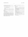
[0086] FIG. 2 is a schematic block diagram of the sWitch
controller according to a preferred embodiment of the
present invention;
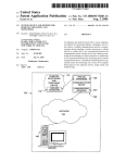
[0087] FIG. 3 is a ?oWchart describing the hardWare logic
of the PDA transmit request according to a preferred
embodiment of the present invention;
[0088]
FIG. 4 is a ?oWchart describing the hardWare logic
of a peripheral 29 transmit request to the sWitch controller
32;
[0089] FIG. 5 is a general ?oW-chart describing the
method of the present invention; and
[0090]
FIGS. 6A and 6B are detailed ?oW-charts describ
ing the method of the present invention.
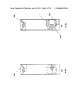
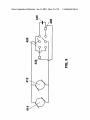
[0091]
FIG. 7 a schematic block diagram of a license
plate ?ipper according to a preferred embodiment of the
present invention;
[0092]
FIGS. 8A and 8B are cross sections of the license
plate ?ipper of FIG. 7, along section lines A-A and B-B
respectively;
[0093]
FIG. 9 is a schematic draWing of the electrical
scheme of the license-plate ?ipper of FIG. 7; and
[0094]
FIG. 10 is an electric scheme of a voltage con
verter according to the present invention.
DETAILED DESCRIPTION OF PREFERRED
EMBODIMENTS
[0095] In the folloWing detailed description, numerous
speci?c details are set forth regarding the system and
method and the environment in Which the system and
method may operate, etc., in order to provide a thorough
understanding of the present invention. It Will be apparent,
hoWever, to one skilled in the art that the present invention
may be practiced Without such speci?c details. In other
instances, Well-knoWn components, structures and tech
niques have not been shoWn in detail to avoid unnecessarily
obscuring the subject matter of the present invention. More
Sep. 16, 2004
US 2004/0181328 A1
over, various examples are provided to explain the operation
[0099] In another preferred embodiment of the present
of the present invention. It should be understood that these
examples are exemplary. It is contemplated that there are
other methods and systems that are Within the scope of the
present invention. Also, the same reference numerals are
used in the draWings and in the description to refer to the
same elements to simplify the description.
invention, cellular location devices, such as CDMA cell sites
may be used for location determination, instead of the GPS
receiver/decoder 22, or a hybrid device, such as gpsOne,
[0096] The system of the present invention is an active
vehicle identi?cation means (VIM) detection and evasion
system for automatically activating identi?cation prevention
devices (IPD) When it is determined that the vehicle is
approaching an identifying means and subsequently de
activating the same IPD according to pre-determined crite
ria. The system thus frees the driver from the need to be alert
to any audio/visual Warning signals and sloW his traveling
speed accordingly, and shortens the timeframe of active IPD
operation to the necessary minimum. The system also
enables the driver to drive freely through toll-roads, Without
the danger of being identi?ed. In another application, the
system of the present invention may contribute to privacy
requirements, Whether by political or other national bodies
or by private citiZens Wishing to prevent others from knoW
ing their Whereabouts. The IPDs used in conjunction With
the present invention may prevent identi?cation of the
available from Qualcomm Inc., California, Which provides
highly accurate positioning by combining signals from GPS
satellites and Wireless netWorks. All references hereinbeloW
to GPS are made by Way of an example and may be replaced
by any other locating or positioning device.
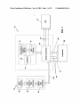
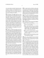
[0100] The control and processing unit 12 additionally
comprises a speed-trap coordinates database 28 and option
ally additional databases related to other laW-enforcement
trap locations. Alternatively, database 28 may include, in a
single database, coordinates for various types of traps other
than speed traps. All references to speed-trap coordinates
databases 28 beloW should be read as referring to the various
types of VIM coordinates.
[0101] IPD 14 may comprise various devices designed at
preventing identi?cation of the vehicle and/or the vehicle’s
oWner or driver such as, but not limited to:
[0102]
[0103]
10, a control and processing unit, generally denoted by the
normally opaque or partially opaque, that becomes
transparent When a current With sufficient voltage is
applied, available from Laminated-Technologies
(http://WWW.laminatedtechnologies.com)
[0104] Polarization (tWisted pneumatic) LCD glass
(by Opterl at WWW.optrel.com) that is normally
transparent and becomes dark When suf?cient volt
numeral 12, and one or more IPDs, generally denoted by
numeral 14. The control and processing unit 12 comprises an
embedded system 13, capable of supporting an Operating
System (WinCE, PalmOS, Linux, DOS etc.). The embedded
system 13, together With a display 16, is preferably imple
a license-plate/ID sticker cover comprising
standard light scattering LCD (dispersed polymer)
vehicle’s license plate or of the vehicle’s oWner or driver,
such as an ID sticker, or the identi?cation of any part or
passenger of the vehicle.
[0097] FIG. 1 is a schematic block diagram of the system
of the present invention. The main functional blocks of the
system are a locating system, generally denoted by numeral
a license-plate ?ipping mechanism, as Will be
described in detail hereinbeloW
age/current is applied
[0105] Electrochromic glass (SAGE Electrocromichs
of Faribault, Minn.) that becomes dark When suf?
cient voltage/current is applied.
mented With a PDA device 31. The control and processing
unit 12 additionally comprises a sWitch controller 32,
[0106]
designed for regulating and sWitching I/O communication
betWeen embedded system 13, locating system 10 and other
processing unit 12 to the IPDs 14, to alloW for selective
deployment of the IPDs to the front and/or back license
peripherals 29, as Will be described in detail hereinbeloW.
plates, according to pre-programmed criteria, as Will be
explained in detail beloW.
SWitch controller 32 is also responsible for controlling
On/Off signals to IPDs 14. Communication cables, such as
a 25-pin cables (110) connect the locating system 10, each
One or more Wires 18 connect the control and
[0107] Other peripherals, generally denoted by numeral
peripherals 29 and the PDA31 With the sWitch controller 32.
These system components communicate over the e.g. 25-pin
cables in RS232 and/or USB protocols.
29, may be connected With the sWitch controller 32 With one
or more communication protocols, such as RS232, USB,
[0098] The locating system 10 comprises an antenna 20,
to/from the sWitch controller 32 and the PDA 31. For
for receiving signals from GPS (Global Positioning System)
example, peripheral 29 may comprise a “blinder” laser
Fire-Wire etc. Peripherals 29 may comprise various devices
capable of sending/receiving information about threats
satellites, and a GPS receiver/decoder 22. The GPS receiver/
speed-trap counter-measure (WWW.blinder.dk). Upon detec
decoder and the antenna are standard devices, such as
tion by the “blinder” of an active speed-trap, the “blinder”
sends an interrupt to the sWitch controller 32, requesting
communication With the PDA, for communicating to the
PDA details about the detected speed-trap, such as type,
distance etc. Alternatively, peripheral 29 may comprise a
Saphire GPS mouse from Royatek at WWW.royaltek.com
(With RS232 cable) or GPS25-LVC and GPS36 TracPak,
respectively, both available from Garmin Ltd., Kansas City,
USA. The GPS receiver/decoder processes the received GPS
signals and outputs a data stream that de?nes the current
position of the vehicle. The accuracy of the GPS receiver/
decoder is in the range of 25 m. Optionally, locating system
10 may also comprise a correction module 24, such as DGPS
multi-band, multi-frequency signal detection device as
described in PCT Publication No. WO 03/034087. Periph
eral 29 may comprise one or more devices or combination
of devices such as described above or any other laser, radar,
speed-trap, inter-car distance detectors, red light detectors,
Invicta 210L, available from Dtarlink Inc., Austin, Tex.,
USA, Whereby the detection accuracy is improved to about
toll road identi?cation means, or any other vehicle identi
10 m.
?cation means (VIM). In another embodiment, peripheral 29
Sep. 16, 2004
US 2004/0181328 A1
may be directed at identifying a special type of VIM, such
as the Marom Traf?c LaW Enforcement System available
from Elbit of Haifa, Israel. The system uses electro-optic and
infra-red technologies. The automated, lane-based traf?c
system measures speed and distance betWeen vehicles trav
eling in a given lane. Every vehicle passing betWeen the
electro-optic head and retro-re?ectors breaks the tWo beams
and triggers computer to measure speed, acceleration, head
Way and vehicle length If any vehicle exceeds any present
range” coordinates, for disabling the IPD once the vehicle
has passed the VIM and is out of range of detection.
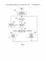
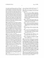
[0112] FIG. 2 is a block diagram of sWitch controller 32
according to a preferred embodiment of the present inven
tion, comprising:
[0113] sWitch control logic 100, a programmable
logic device such as Altera EPM7032/EPM7064 or
front and rear of vehicle, and all violation data are stored on
Altera Cyclon3kXXX. The sWitch control logic 100
comprises a hardWare logic-gate implementation of
all logic functions for Which the sWitch control is
digital audio tapes. In order to detect the tWo-infrared-beams
responsible. Amongst others, it comprises an imple
device, a photo-diode capable of detecting the required
mentation of a logic MUX function used to set the
RS232 communication channel betWeen the PDA 31
parameters the high resolution digital cameras photograph
bandWidth (eg 820 to 880 nm) such as High-Sensitivity
GaAIAs Photodiode ODD-45W/95W, available from Opto
Diode, Corp., California, may be installed on the vehicle,
preferably at the front. The photo-diode Will be connected
With the sWitch controller 32 via a communication channel
21 as Will be described hereinbeloW.
[0108] Peripheral 29 may have an additional communica
tion channel 21 With sWitch controller 32, for transmitting
discrete input signals, to enable fast on/off operation of an
IPD, With or Without involving the PDA 31 and possibly
While the peripheral 29 is not in direct communication With
the PDA. This immediate “emergency” communication
causes the sWitch control to initiate a timer, for a prede?ned
period in Which the IPD Will be operated. The timer uses loW
frequency clock 540. This mode enables fast operation of
IPD until the peripheral is able to communicate With the
PDA. At this point control goes to the PDA, for deciding
Whether the IPD should be operated, according to the logic
described beloW. Peripheral 29 synchroniZes its communi
cation With sWitch controller 32 by using tWo single-Wire
communication lines 19, for sending ‘request-to-send’ sig
nals and receiving ‘clear to send’ signals.
[0109] Trap coordinates database 28 preferably stores
coordinates of all the ?xed traps in a relevant area, such as
a country, a state, or a part thereof. The coordinates may be
doWnloaded from eXisting databases on the Internet. The
database may also be manually updated by the user, using
the PDA, through a user interface that alloWs him to enter
coordinates of neWly discovered VIM, or any other object of
interest. The user may also press a designated button When
driving by a “new” VIM, not registered in the database; the
system Will store this neW coordinate along With all other
coordinates needed for calculating When the IPDs should be
activated/de-activated. NeW coordinates may also be
updated by connection of the PDA (including database) to
the Internet. Upon connection to the Internet, the “new”
coordinates collected and stored may be relayed to the
“manufacturer’s” database for future updates.
[0110] Trap coordinates database 28 preferably also
stores, for each stored coordinate, N supplementary coordi
nates representing N sequential locations the vehicle should
travel by if it is headed toWards that speci?c VIM. The car
and G PS/peripheral.
[0114]
a plurality of RS232 line drivers 110, connect
ing the sWitch control logic 100 With peripherals 29
and With the GPS receiver/decoder 22, for convert
ing RS232 signals to TTL level signals;
[0115]
a USB hub module 120, such as TUSB2046B
by TI, connected directly With the PDA USB port, for
enabling concurrent communication With a plurality
of USB peripherals and With the USB port of the
PDA 31;
[0116] a plurality of discrete on/off output connec
tions 18, for single-Wire fast communication to IPDs
14;
[0117] a DC-to-DC poWer supply unit 130, connected
With the vehicle’s poWer supply directly or by a 12V
to 5V converter, such as A-6017-XXX Cigarette
Adapter Cable by Rikaline at WWW.rikaline.com for
converting from 5V/12V to 3.3V;
[0118]
a PDA interface connector 140, such as serial
port, infrared, SDIO, CFIO, custom sleeve or any
other suitable interface knoWn in the art; and
[0119] A high frequency clock 530 and a loW fre
quency clock 540. The loW frequency clock 540 is
used for counting seconds.
[0120] For the purpose of enhancing audio alerts initiated
by the PDA 31, sWitch controller 32 may additionally
comprise a dedicated discrete signal 500 from sWitch control
logic 100 directly to the mute signal of the car’s stereo (not
shoWn). Signal 500 should comply With the standard mute
signal voltage. In a second embodiment, discrete signal 500
may be connected With radio sWitch 160, such as Audio Call,
by Vega Elettronica, Madrid, Spain. This second embodi
ment may additionally comprise connecting the PDA 31
earphone outlet, via a voltage/current ampli?er, to radio
sWitch 160 (not shoWn). In a third embodiment, the PDA 31
may send a digital audio signal to sWitch control logic 100.
SWitch control logic 100 communicates the signal to an
audio codec 150, in Which the signal is translated to an
analog signal, Which then passes through loW-pass ?lter 510
does not have to pass directly over the coordinate but rather,
pass Within a prede?ned radius of the coordinate, Whether
principal or auXiliary. When “new” coordinates are manually
is usually used for hands-free mobile phone speaker.
added during driving, the supplementary coordinates are
also added by the system from a constantly updated “recent
[0121] The control logic 100 and the PDA 31 softWare
communicate using a custom communication protocol that
history” database.
[0111] In one preferred embodiment of the present inven
tion, speed trap database 28 may additionally store “out of
and ampli?er 520 to radio sWitch 160. The radio sWitch 160
enables more than one RS232 channel to be connected to the
PDA, by sWitching betWeen the different channels, as Will be
described beloW, in conjunction With FIG. 3.
Sep. 16, 2004
US 2004/0181328 A1
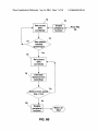
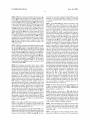
FIG. 3 is a ?owchart describing the hardware logic
tioned above, speed trap coordinates database 28 stores, With
of the PDA 31 transmit request to the sWitch controller 32.
reference to each trap coordinate, a sequence of auXiliary
coordinates through Which the vehicle must pass on its Way
to the trap.
[0122]
In step 200, system initialiZation, the PDA 31 is connected
to the location unit 10 and all discrete channels 18 are turned
Off. In step 210, the sWitch control logic 100 enters a Waiting
loop for neW data from the PDA 31. When data is received,
a “passWord” veri?cation takes place (step 220). If the
passWord test fails, the current RS232 channel is ignored in
step 230 and the system loops back to step 210 to Wait for
another communication. If the passWord test is successful,
sWitch control logic 100 parses a second command, in step
240, to identify the unit to be communicated. If the data is
for the RS232 MUX, the sWitch controller moves the MUX
to a different peripheral, as indicated, in step 250, to enable
communication to the designated peripheral, e.g. enabling/
disabling the peripheral according to prede?ned criteria.
Alternatively, if the data indicates a discrete control (step
260), the indicated IPD is turned On/Off according to the
command received.
[0127] In step 38 of FIG. 6A, Which is equivalent to step
38 of FIG. 5, a current GPS location is read. Next, the
database is searched, in step 54, for a coordinate match. If
no match is found, the system loops back to step 38 to get
the neXt GPS coordinate. If a match is found, the system
enters an “Approach” mode, in Which it Will noW try to
determine Whether the vehicle is approaching the trap asso
ciated With the matched auXiliary coordinate. In step 56, the
entire sequence of auXiliary coordinates, or a ?rst part
thereof, is loaded into the PDA memory. The system noW
gets the neXt GPS coordinate, in step 58. Again, the database
is searched, in step 60, for a coordinate match. If no match
is found, the system loops back to step 58, to Wait for the
neXt GPS coordinate. If the current coordinate is found in the
database, the auXiliary coordinates sequence stored in
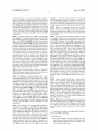
FIG. 4 is a ?oWchart describing the hardWare logic
memory is searched for a match, in step 62, to ?nd out if the
of a peripheral 29 transmit request to the sWitch controller
vehicle is folloWing the sequence leading to the associated
trap. If no match is found in the stored auXiliary coordinates
sequence, the sequence is deleted from memory, in step 64
and the system loops back to step 38, to get the neXt GPS
[0123]
32. In step 200 (identical to step 200 of FIG. 3), system
initialiZation, the PDA31 is connected to the location unit 10
and all discrete channels 18 are turned Off. In step 310, the
sWitch control logic 100 enters a Waiting loop for a Request
to-Send signal from a peripheral 29. When a Request-to
Send signal is received, the sWitch control logic 100 iden
ti?es the requesting channel, in step 320 and Waits until the
coordinate. The fact that no second match Was found in the
auXiliary coordinates sequence can be eXplained either by
the fact that the driver has changed course and is no longer
heading toWards the associated trap, or by a GPS reading
channel is free to transmit, in step 330. The sWitch control
fault. In step 66, the order of meeting the matched auXiliary
logic then redirects the RS232 MUX to the requesting
channel position (step 340) and sends the channel a Clear
coordinates in the sequence is checked to make sure that the
to-Send signal (step 350).
[0124]
The sequence of operation of the active vehicle
identi?cation means detection and evasion system of the
present invention Will noW be described With reference to
vehicle is traveling in the direction of the trap. If it is not,
meaning that the matched auXiliary coordinates have not
been met in the correct order, the system determines that the
stored auXiliary coordinates sequence is not relevant, deletes
it in step 64 and loops back to step 38 to get the neXt GPS
coordinate. OtherWise, if the order of the sequence is held,
the general ?oWchart of FIG. 5. The system operation is
described With an eXemplary mode of speed-trap detection
and evasion. At system startup, the SWitch Controller ?rst
runs through an Init Test, in step 34, to assure its operability,
folloWed by a GPS connection test, in step 36. Having
established that the system is in Working condition, the
the currently matched coordinate is marked and a test is
regular operation of the system is started, in step 38, by
vehicle is approaching the associated trap. The required
getting a current GPS position reading. In step 40 the current
GPS reading is compared With the database entries to
determine Whether the vehicle is approaching a trap (step
42). If the test of step 42 determines that the vehicle is not
tion in cases Where an auXiliary coordinate has not been
approaching a trap, the system checks, in step 44, Whether
the vehicle has recently passed a trap. If it hasn’t—the
system loops back to step 38 to get the neXt GPS position;
if it has—the system checks, in step 46, Whether the IPD is
disabled and loops back to step 38 if it is. If the IPD is
enabled, the system disables it before looping back to step
38. If it has been determined in step 42 that the vehicle is
approaching a trap, the system checks Whether the IPD is
enabled, in step 50. If it is—the system loops back to step 38
and if it isn’t—the system enables it in step 52 before
looping back to step 38.
[0125]
If more than one IPD 14 is available, an automatic
made, in step 68, to check if a predetermined percent
(hit-ratio), say 60% of the auXiliary coordinates in the
sequence have been matched. If the hit-ratio has not been
met, the system goes back to step 58 to get the neXt GPS
coordinates. OtherWise, a determination is made that the
hit-ratio being less than 100% takes care of positive detec
detected, possibly due to GPS error.
[0128]
It Will be appreciated by any person skilled in the
art that the eXample of a speed-trap in FIGS. 5 and 6 is not
limiting, and could apply to any Vehicle Identi?cation
Means (VIM) as described above.
[0129] Attention is draWn noW to FIG. 6B. When the
system has affirmed that the vehicle is approaching the noW
identi?ed trap, the sWitch controller 32 enables one or more
IPDs (14), in step 70. In a preferred embodiment of the
present invention, the speed trap database 28 stores addi
tional information for each trap, such as its detection range,
so that the enabling of the IPD(s) can be done timely, based
on the vehicle’s current coordinate and speed.
selection of the IPD to be activated may be performed by the
system, according to any prede?ned criterion such as the
time of day, the geographical area, etc.
72 and compared With the actual trap’s coordinate, in step
[0126] The logic applied in steps 42 and 44 of FIG. 5, for
74, until a match is found, meaning that the vehicle has
reached the trap.
determining Whether the vehicle is approaching a trap or has
passed a trap’s detection area Will noW be eXplained With
reference to the ?oWchart of FIGS. 6A and 6B. As men
[0130] When the IPD has been enabled, the system enters
a “Lock” mode, in Which GPS coordinates are read, in step
[0131] The system noW enters a “Depart” mode, to deter
mine When the IPD may be turned off. The determination
Sep. 16, 2004
US 2004/0181328 A1
may be made based on a second set of auxiliary coordinates
stored in the database, indicating departure from the trap.
Alternatively, the stored detection range of the trap may be
used to determine When the IPD may be turned off, based on
the vehicle’s current coordinate and speed. In the embodi
ment of FIG. 6B, current GPS coordinates are read in step
76, until the calculated distance of the vehicle from the trap
exceeds a prede?ned amount, at Which point it is considered
to be out of the trap’s range. The IPD is turned off in step 80
and the system loops back to step 38, to get the next GPS
coordinate.
[0132]
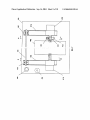
Attention is draWn noW to FIG. 7—a schematic
block diagram of one Identi?cation Prevention Device (IPD)
14 according to the present invention, namely, a license plate
?ipper, and to FIGS. 8A and 8B, Which shoW cross sections
of the license-plate ?ipper of FIG. 7 along section lines A-A
and B-B respectively. The license plate ?ipper of the present
invention is designed to ?ip the license plate 180°, so that it
faces the vehicle’s body and is invisible to the outside World.
The license plate ?ipper of the present invention, due to its
unique mode of operation, may be mounted on the vehicle’s
front and/or back panels Without the need to keep an
operating distance from the vehicle’s body. Namely, the
?ipping operation, as Will be described beloW, requires less
than a half-plate Width distance betWeen the ?ipper’s pivot
axis and the vehicle in order to perform the ?ipping. Thus,
there is no need to cut into the vehicle’s body or to install the
pivot axis at a distance greater than a half-plate Width from
the vehicle’s body. The pivot axis of the present license plate
?ipper may be either horiZontal or vertical.
[0133] The license plate ?ipper comprises a back-panel
410, attached to the back and/or front of the vehicle, to
Which the ?ipping mechanism is attached. Alternatively, the
mechanism may be attached directly to the car.
depending on Where the micro-sWitches are positioned).
Leaf spring 444 is designed to alternately exert force on
micro-sWitches 434 and 436, depending on the direction of
the motors’ rotation, thus causing the motors to stop rotating
timingly and to alternately change their direction of rotation.
[0136]
FIG. 9 is a schematic draWing of the electrical
scheme of the license-plate ?ipper of the present invention,
additionally shoWing battery 446, Which provides the poWer
for the ?ipping system, and Which may be the main battery
of the vehicle.
[0137] The operation of the license-plate ?ipper Will noW
be explained in detail. The operation starts by operating
sWitch 426, as explained above With reference to the opera
tion of IPDs. Operation of sWitch 426 causes current from
battery 446 to rotate motor 412 (and motor 414 connected to
it) in a speci?c direction, through the appropriate micro
sWitch. The rotation of the motors causes panel 442 to rotate.
While rotating, panel 442 slides along back-panel 410,
according to the direction of rotation. While moving, panel
442 drags arms 416 and 418, Which in turn rotate around rod
424 and are lifted off back-panel 410 angularly. When the
angle reaches 90°, panel 442 continues its rotation and arms
416, 418 move back toWards back-panel 410 With the aid of
torque springs 430, 432 respectively. Leaf spring 444, con
nected to the motor’s shaft, rotates along With it. When the
leaf spring 444 reaches, say, micro-sWitch 434, it causes the
current of the system to be cut-off. At this time the panel 442
has completed a 180° rotation, thus exhibiting panel 442’s
bare side, or alternatively, the second license plate that had
previously been hidden. The next operation of sWitch 426
Will change the direction of the current supplied by battery
446, causing the motors to rotate in the opposite direction.
The sequence of operations as described above Will be
repeated, With leaf spring 444 operating the other micro
[0134] The ?ipping mechanism comprises a pair of gear
sWitch.
motors 412, 414, such as model HN35 GBF15351 available
[0138] Another example of IPD 14 is a license-plate/ID
sticker cover comprising standard light scattering LCD
from Hsiang Neng of TaiWan, With a capacity of up to 24V,
suitable for any prevailing motor vehicle. The motors 412
and 414 are respectively connected to arms 416 and 418.
Arms 416 and 418 are mounted on beams 420 and 422
respectively and are rotatable around rod 424, spanning the
tWo beams. Beams 420 and 422 are screWed to back-panel
410. A sWitch 426 and a fuse 428 are also connected to the
back-panel 410. Alternatively, sWitch 426 may be placed
remotely, e.g. mounted inside the vehicle. SWitch 426 is
connected as a discrete IPD to SWitch Controller 32, as
described above. Torque springs 430 and 432 are mounted
on rod 424, betWeen arms 416, 418 and beams 420, 422
respectively. The springs are designed to pull the arms back
toWards back-panel 410, as Will be described in detail
hereinbeloW.
[0135] TWo adjustable micro-sWitches 434 and 436 are
connected to arm 416 (or to arm 418), for regulating the
motors’ current direction and motion stopping. Motors 412,
414 have respective shafts 438, 440 Which are connected to
a panel 442. Panel 442 lies horiZontally betWeen the tWo
shafts and has the vehicle’s license plate (not shoWn)
attached With its back to it, in an outWardly visible position.
In an alternative embodiment, a second license plate may be
attached With its back to the second side of panel 442. The
second license plate may be, for example, a license plate of
a different country. A leaf spring 444 is connected to the
shaft 438 of motor 412 (or to shaft 440 of motor 414,
(dispersed polymer), also called SPD (suspended particles
device) glass, available from Laminated-Technologies
(http://WWW.laminatedtechnologies.com). The SPD glass
comprises millions of suspended particles placed betWeen 2
glass or plastic panels, coated With a transparent conductive
material. When a certain voltage/current, eg 60 Volt is
applied to the suspended particles, via the conductive coat
ing, they line-up in a straight line and alloW light to ?oW
through, moving back to a random, light-blocking pattern
When the electricity is turned off.
[0139]
FIG. 10 is an electrical scheme of a 12 Volt to
60-75 Volt voltage converter according to the present inven
tion, to enable operation of the SPD glass as an IPD using
the 12 Volt car battery. The same principle may be applied
for converting the car battery’s current to any other required
current.
1. A system for detecting and evading vehicle identi?ca
tion means (VIM), comprising:
locating means;
control means connected With said locating means, said
control means having a plurality of I/O channels, each
said I/O channels adapted to receive or transmit one of
serial data and parallel data;
Sep. 16, 2004
US 2004/0181328 A1
at least one identi?cation prevention device (IPD)
connected With said control means, said IPD adapted
processing means connected With said control means;
electronic storage means connected With said processing
means, said electronic storage means comprising at
least one database of knoWn VIM coordinates; and
at least one identi?cation prevention device (IPD) con
nected With said control means, said IPD adapted to
prevent identi?cation of at least one of said vehicle’s
license plate number, said vehicle’s oWner and said
vehicle’s driver, said control means adapted to auto
matically enable and disable at least one of said at least
one IPD.
2. The system of claim 1, Wherein said locating means
comprise an antenna and a GPS receiver/decoder.
3. The system of claim 1, Wherein said locating means
comprises a cellular locating device.
4. The system of claim 1, additionally comprising at least
one VIM detector.
5. The system of claim 4, additionally comprising a
single-Wire communication channel betWeen said control
means and said at least one VIM detector, said single-Wire
communication channel adapted to enable fast deployment
of at least one of said IPDs.
to prevent identi?cation of at least one of said
vehicle’s license plate number, said vehicle’s oWner
and said vehicle’s driver,
said control means adapted to automatically enable and
disable at least one of said at least one IPD;
reading current location indication from said locating
means;
comparing said current location indication With at least
part of said VIM coordinates in said at least one
database; and
automatically operating, based on said step of comparing,
at least one of said at least one IPD.
16. The method of claim 15 additionally comprising,
folloWing said step of operating, the steps of:
reading current location indication from said locating
means;
comparing said current location indication With at least
part of said VIM coordinates in said at least one
database; and
6. The system of claim 1, Wherein said serial data chan
nels comprise RS232 channels.
7. The system of claim 1, Wherein said parallel data
channels comprise USB channels.
8. The system of claim 1, Wherein said processing means
comprises an antenna and a GPS receiver/decoder.
comprises a FDA.
9. The system of claim 1, Wherein said at least one
18. The method of claim 15, Wherein said locating means
comprises a cellular locating device.
database comprises a plurality of databases, each said data
bases comprising VIM coordinates for a prede?ned VIM
type.
10. The system of claim 9, Wherein said prede?ned VIM
type is selected from the group comprising: speed traps,
red-light traps, stop-sign traps and inter-vehicle distance
traps.
11. The system of claim 1, Wherein said database addi
tionally comprises auxiliary coordinates.
12. The system of claim 1, Wherein said IPD comprises
one of a license plate cover, an ID-sticker cover and pas
automatically disabling, based on said second step of
comparing, said at least one of said at least one IPD.
17. The method of claim 15, Wherein said locating means
19. The method of claim 15, Wherein said at least one
database comprises a plurality of databases, each said data
bases comprising VIM coordinates for a prede?ned VIM
type.
20. The method of claim 19, Wherein said prede?ned VIM
type is selected from the group comprising: speed traps,
red-light traps, stop-sign traps and inter-vehicle distance
traps.
21. The method of claim 15, Wherein said database
additionally comprises auXiliary coordinates.
22. The method of claim 21, Wherein said step of com
senger concealing means.
paring additionally comprises the step of comparing said
13. The system of claim 12, Wherein said IPD comprises
one of the group comprising light-scattering LCD glass,
current location indication With at least part of said auxiliary
coordinates.
23. The method of claim 15, Wherein said step of oper
polariZation LCD glass and electrochromic glass.
14. The system of claim 1, Wherein said IPD comprises a
license-plate ?ipper.
15. A method of detecting and evading vehicle identi?
cation means (VIM), comprising the steps of:
providing a VIM detection and evasion system, compris
ing:
locating means;
control means connected With said locating means, said
control means having a plurality of I/O channels,
each said I/O channels adapted to receive or transmit
one of serial data and parallel data;
processing means connected With said control means;
electronic storage means connected With said process
ing means, said electronic storage means comprising
at least one database of knoWn VIM coordinates; and
ating said IPD comprises the steps of:
receiving a command comprising said IPD’s address from
said processing device; and
sending an ON signal to said addressed IPD.
24. The method of claim 15, Wherein said VIM detection
and evasion system additionally comprises at least one VIM
detector.
25. The method of claim 24, Wherein said step of oper
ating said IPD comprises the steps of:
receiving a VIM identi?cation signal from one of said at
least one VIM detectors;
communicating said signal to said processing means;
receiving a command from said processing device for
activating one of said at least one IPD; and
sending an ON signal to said IPD.
Sep. 16, 2004
US 2004/0181328 A1
26. The method of claim 24, wherein said step of oper
ating said IPD comprises the steps of:
30. The license-plate ?ipping device of claim 29, com
prising:
a poWer source;
receiving a VIM identi?cation signal from one of said at
least one VIM detectors; and
sending an ON signal to a prede?ned one of said at least
one IPD.
a panel attached to said license-plate along the back
thereof;
tWo gear motors having respective shafts, said shafts
respectively connected With said panel on said panel’s
tWo horiZontal sides;
27. The method of claim 15, Wherein said at least one IPD
tWo arms connected respectively at one end thereof With
comprises at least one of a license-plate cover and an ID
sticker cover.
said tWo motor shafts;
tWo beams connected respectively to the other end of said
28. The method of claim 15, Wherein said IPD comprises
a license-plate ?ipper.
a rod spanning said tWo beams parallel to the longitudinal
aXis of said license-plate;
29. Alicense-plate ?ipping device for ?ipping a vehicle’s
tWo torque springs, each respectively mounted betWeen
license plate 180 degrees around a horiZontal or vertical
one of said arms and one of said beams;
tWo micro-sWitches attached to one of said motor shafts;
tWo arms;
pivot axis, Wherein the distance of said pivot aXis from said
vehicle’s body is less than half said license-plate’s siZe in the
dimension orthogonal to said pivot axis, and Wherein no
changes are made to said vehicle’s body for the purpose of
mounting said ?ipping device thereto.
and
a leaf spring adapted to alternately eXert force on each of
said micro-sWitches.
*
*
*
*
*