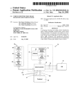
1
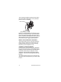
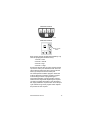
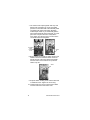
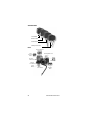
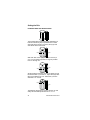
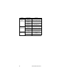
Flomatic
Beverage Valves
Technician’s
Handbook
This manual is updated as new information and models
are released. Visit our website for the latest manual.
www.manitowocfsg.com
America’s Quality Choice in Refrigeration
Part Number STH15 9/10
Safety Notices
As you work on Manitowoc equipment, be sure to pay
close attention to the safety notices in this handbook.
Disregarding the notices may lead to serious injury
and/or damage to the equipment.
Throughout this handbook, you will see the following
types of safety notices:
! Warning
Text in a Warning box alerts you to a potential
personal injury situation. Be sure to read the
Warning statement before proceeding, and work
carefully.
! Caution
Text in a Caution box alerts you to a situation in
which you could damage the equipment. Be sure
to read the Caution statement before proceeding,
and work carefully.
Procedural Notices
As you work on Manitowoc equipment, be sure to read
the procedural notices in this handbook. These notices
supply helpful information which may assist you as
you work.
Throughout this handbook, you will see the following
types of procedural notices:
Important
Text in an Important box provides you with
information that may help you perform a
procedure more efficiently. Disregarding this
information will not cause damage or injury, but it
may slow you down as you work.
NOTE: Text set off as a Note provides you with simple,
but useful, extra information about the procedure you
are performing.
Read These Before Proceeding:
! Caution
Proper installation, care and maintenance are
essential for maximum performance and troublefree operation of your Manitowoc equipment. If
you encounter problems not covered by this
handbook, do not proceed, contact Manitowoc
Foodservice Group. We will be happy to provide
assistance.
Important
Routine
adjustments
and
maintenance
procedures outlined in this handbook are not
covered by the warranty.
! Warning
PERSONAL INJURY POTENTIAL
Do not operate equipment that has been misused,
abused, neglected, damaged, or altered/modified
from that of original manufactured specifications.
We reserve the right to make product
improvements at any time. Specifications and
design are subject to change without notice.
Table of Contents
General Information
Model Numbers . . . . . . . . . . . . . . . . . . . . . 7
How to Read a Model Number . . . . . . . . . 8
Model/Serial Number Location . . . . . . . . 8
Accessories . . . . . . . . . . . . . . . . . . . . . . . 8
Special Applications . . . . . . . . . . . . . . . . 12
Warranty Information . . . . . . . . . . . . . . . . 12
Installation
Pre-installation Checklist . . . . . . . . . . . . . 13
324, 424 & 464 Valves . . . . . . . . . . . . . . . 13
Component Identification
Valve Types . . . . . . . . . . . . . . . . . . . . . . . . 19
Levers . . . . . . . . . . . . . . . . . . . . . . . . . . . . 21
Maintenance
Maintenance Schedule . . . . . . . . . . . . . . . 23
Cleaning and Sanitizing the Dispensing
Valves and Product Lines . . . . . . . . . . . . 25
Sanitizing . . . . . . . . . . . . . . . . . . . . . . . . . 28
Setting the Brix . . . . . . . . . . . . . . . . . . . . . 32
Operation
Flow Rate . . . . . . . . . . . . . . . . . . . . . . . . . 33
Automatic Fill Valve . . . . . . . . . . . . . . . . . 34
Troubleshooting
Checklist . . . . . . . . . . . . . . . . . . . . . . . . . . 35
Carbonated Water System . . . . . . . . . . . . 37
Circulating System . . . . . . . . . . . . . . . . . . 44
Dispensing Valve . . . . . . . . . . . . . . . . . . . 45
When the Brix is OFF . . . . . . . . . . . . . . . . 50
Component Check Procedures
RATIO . . . . . . . . . . . . . . . . . . . . . . . . . . . . 53
BUZZING . . . . . . . . . . . . . . . . . . . . . . . . . . 53
LEAKS . . . . . . . . . . . . . . . . . . . . . . . . . . . . 53
Every 6 months (2 times per year) . . . . . 53
Part Number STH15 9/10
5
Component Specifications
Flow Rates . . . . . . . . . . . . . . . . . . . . . . . .
424 Specifications . . . . . . . . . . . . . . . . . .
464 Specifications . . . . . . . . . . . . . . . . . .
Product Viscosity . . . . . . . . . . . . . . . . . .
6
57
57
58
58
Part Number STH15 9/10
General Information
Model Numbers
This manual covers the following models:
424
464-GP
372-Q (Back Block)
380-Q (Back Block)
Tower
Part Number STH15 9/10
7
How to Read a Model Number
VALVE MODEL NUMBERS
Model Suffix
Model Base
464
454
424
324
202
464–GP
GP - Global Performance
HF - High Flow
With all models, mounting and ratio control are the same.
All Flomatic valves are identified by a Model Number,
Serial Number, a manufacture month and year on the
underside of the flow control base. These numbers are a
helpful reference before beginning any valve service.
Model/Serial Number Location
This number is required when requesting information
from your local distributor. All Flomatic valves are
identified by a Model Number, Serial Number, a
manufacture month and year on the underside of the flow
control base. These numbers are a helpful reference
before beginning any valve service
Accessories
Manitowoc Foodservice developed this manual as a
reference guide for the service agent and installer of
fountain equipment.
Fountain dispensing is the serving of a beverage (soft
drink, tea, or juice, etc.) from a dispenser that will chill
the product to an acceptable serving temperature for
the consumer.
The beverage, delivery system and dispenser can be
postmix or premix. The system may be an elaborate
system with most of the components in the back of the
store and the dispenser in the front. Fountain systems
could be a simple system with the complete system
under the counter where the dispenser is located.
Our goal is that this manual will remove some of the
confusion, and mystery of beverage dispensing
equipment while providing a general overview of
service to the equipment.
8
Part Number STH15 9/10
VALVES
Most Flomatic valves are available in sanitary push
lever, push button,automatic fill lever, and portion
control models.
Replacement
Flomatic created a kit (5007842) to replace both the 372-Q
or 380-Q Flomatic mounting blocks. All Flomatic mounting
blocks are identical in appearance, except for the part
numbers shown on the front recess of the block. The 380Q has inlet ports sized at 0.380 in. The 372-Q inlet ports
are sized at 0.372 in.
WHAT IS CARBONATION
Carbonation is the process of mixing carbon dioxide gas
into a liquid (water). The resulting liquid is called soda
water or carbonated water. The carbon dioxide gas is the
bubbles you see when a carbonated beverage (like soda)
is dispensed.
Most cola, lemon-lime products, etc. are carbonated.
Normally teas, juices, etc. are noncarbonated.
Some beverage technicians refer to noncarbonated water
as sweet water.
WATER CHARACTERISTICS
Water makes up over 80% of the typical finished
beverage. The quality of this primary ingredient is of
utmost importance. You should use regular cold tap water,
not water that has been through a water softener,
conditioner, etc. Any off taste or color should be treated by
proper water filtration.
Part Number STH15 9/10
9
WATER FILTERS
It is recommended that proper water filters treat the water
supply for the beverages. There are two basic filters
commonly in use.
1. Pre-filter, or sand filter. This filter removes any foreign
matter from the water down to 25 microns in size.
2. Carbon or activated charcoal filter is also used. This
filter will reduce chlorine and other chemicals, offtaste and odor. Some of the higher quality filters may
reduce organic compounds (bacteria) in the water.
Do not use a filter containing any type of phosphate on the
beverage system. Phosphate as used for scale reduction
will cause the beverage to loose its carbonation and
become “flat” quickly.
WATER PRESSURES
Dynamic (flowing) water pressures to most
carbonators should be a minimum of 40 PSI. Water
pressure to dispensers for noncarbonated beverages
should be a minimum of 60 pounds. These pressures
are minimum operating pressures, not static pressure.
SYRUP BASICS
Your concentrated syrup containers should be stored
in a cool dry location that is easily accessible. Any
extremes in temperature can wreak havoc with the
quality of the product. For best results, the syrup
should be maintained in an environment between 40
and 90 degrees.
PREMIX
Premix fountain dispensing consists of a container
(figal) of beverage ready for dispensing, beverage
delivery system, carbon dioxide (CO2) propellant,
beverage cooling system, and dispenser. We shall
discuss each component of this type of system within
the context of this manual.
The major advantage of a premix system over most
other types is its flexibility. This flexibility is the ability to
go anywhere. Many premix systems will operate
without electric power or separate water supply.
10
Part Number STH15 9/10
POSTMIX
Postmix fountain dispensing consists of either a tank
(called a Figal) or a box (called a Bag-in-Box) of
beverage syrup. The postmix system will also include
the carbonator, fresh water supply, carbon dioxide
(CO2) supply, syrup delivery system, beverage cooling
system, and dispenser. We shall discuss each
component of this type of system within the context of
this manual.
The major advantage of the postmix system over most
other systems is the very low cost of delivering a high
quality, fresh beverage to the consumer utilizing less floor
and storage space for the quantity of beverages served.
PIPING
The fountain system is connected together by a series
of tubing or hoses. This tubing is called beverage tube
or hose and is commonly available in 1/4”, 3/8”, and 1/
2” inside diameters. Beverage hose is a flexible, highpressure hose. This hose is capable of withstanding
system pressures in excess of 100 PSI. The beverage
hose may be an individual line or assembled with
many lines of hose bundled together.
The beverage tubing or hose is attached to the various
components of the system with barbed stems, nuts,
tees, etc. The tubing is held onto the fittings with small
tube clamps called stepless (Oetiker®) clamps. When
attaching the tubing and fitting to a “flared” fitting, the
use of a flare washer is required.
Several different type of tubing are available for the
beverage industry. If there is any possibility of the
tubing laying in a damp environment, the use of nonpermeable tubing should be used. Tubing is also
available as a single tube or bundled together. Single
tube is available as non-permeable plastic or stainless
steel. Bundled tube is available as plastic only.
Part Number STH15 9/10
11
Special Applications
OUTDOOR APPLICATIONS
Flomatic Valves are approved and listed by
Underwriters Laboratories (UL). However they are not
UL approved for weather exposure applications.
These units must be installed in areas where adequate
protection from the elements is provided, all other
models are ETL listed.
! Warning
Personal Injury Potential
Do not operate equipment that has been misused,
abused, neglected, damaged, or altered/modified
from that of original manufactured specifications.
Warranty Information
Consult your local distributor for terms and conditions
of your warranty. Your warranty specifically excludes
all beverage valve brixing, general adjustments,
cleaning, accessories and related servicing.
No equipment may be returned without a written
Return Materials Authorization (RMA). Equipment
returned without an RMA will be refused at the dock
and returned to the sender at the sender’s expense.
Please contact your local distributor for return
procedures.
12
Part Number STH15 9/10
Installation
Pre-installation Checklist
When installing any system, first make sure the
following has been done:
Relieve the system pressure before
removing or repairing the mounting block.
Determine which mounting block you need.
324, 424 & 464 Valves
These valves are available in manual, electric, portion
control and automatic fill models. All of these Flomatic
valves share the same mounting and flow control
characteristics. The 324 valves are also compatible
with the 300-Q mounting block.
Flomatic created a kit (5007842) to replace both the
372-Q or 380-Q Flomatic mounting blocks. All
Flomatic mounting blocks are identical in appearance,
except for the part numbers shown on the front recess
of the block. The 380-Q has inlet ports sized at 0.380
in. The 372-Q inlet ports are sized at 0.372 in. Select
the appropriate mounting option and install the
mounting block. Wet the inlet O-rings with water to
ease installation; do not use Vaseline®. Align the four
bolt holes and mount.
Important
Be sure to relieve the system pressure before
removing or repairing the mounting block.
Remove the valve cover and align the valve stems
with the mounting block. Independent positive
shut-offs and the locking system prevent removal
while the system is pressurized. The valve cannot be
removed unless the shut-off valves are closed (arrows
pointed across service line).
Part Number STH15 9/10
13
The mounting hole pattern typically has key slots to
secure the product supply lines. If no key slots are
present, use the “S” clip option.
Shut-off closed
Valve should seat securely
Engage the valve and depress the latch pin. Do not
force or you could bend the pin. If you have difficulty,
remount the valve and try again. Be sure the valve
base is completely seated against the block. Open the
shut-off valves by turning 1/4 turn (arrows pointed
toward service line) to engage system pressure.
INSTALL ADD-A-LEVER FOR “SODA ONLY”
The Flomatic Add-a-Lever is a two-piece assembly
which mounts on the pivot pin. Remove the cover,
partially withdraw the pivot pin to allow mounting,
reinsert the pin then replace the cover.
CONVERT TO PORTION CONTROL
Flomatic portion control electronics are contained in
the cover and can be factory or field installed. When
installing in the field, the 5031015 Conversion Kit for
the 464-GP makes it easy to add portion control.
The portion control module is designed to simplify
installation. The board can be programmed with the
first pour.
The “Stop/Fill” button serves as a top-off button and
cancels any of the timed portions if you need to abort
the pour.
14
Part Number STH15 9/10
464 Portion Controls
Hidden Program Switch
424 Portion Controls
STOP
FILL
Hidden Program
Switch
Each cup size must be programmed separately. Cup
sizes are preprogrammed at the factory:
1 second = small
2 second = medium
3 second = large
4 second = x-large.
Set the flow rate first, brix the valve, and then set the
cup sizes to match your desired flow rate. Once the
valve is brixed, replace the valve cover and set the
times (cup sizes) from the front switch pad.
The switch pad has a hidden “program” switch that
must be held down to keep the module in program
mode. Setting the times or programming is a
two-handed operation; push and hold the program
switch with one finger while dispensing the cup size
you wish to program with another. Once the drink is
full, simply release the cup size button to end the pour
cycle and then let go of the program switch. Repeat
the process for each cup size.
Part Number STH15 9/10
15
The module will remember one top-off cycle
automatically if the foam height requires it to complete
the pour. To program a top-off cycle, begin
programming as described above. Once the foam
crests the top of the cup, PAUSE by removing your
finger from the cup size button. Do not release the
program button. Pause long enough for the foam to
settle, and then continue the pour with your finger on
the same cup size button until the cup is full. The
module will remember the sequence “pour - pause pour” as it was executed.
If you program the top-off feature, be sure to train the
operators so they do not pull a drink before the cycle is
complete. The portion control module will finish the
pour whether a cup is there or not.
TO CONVERT PUSH BUTTON TO SANITARY
LEVER OPERATION
Flomatic Valve With Pallet Actuators
1. Remove the valve cover from the valve.
2. Slide pivot pin far enough to one side to remove
the actuator spacer bushing from between the two
actuator assemblies.
Cover
Pivot Pin
16
Part Number STH15 9/10
3. Slide the pivot pin back into place. Make sure both
actuator assemblies are mounted correctly on the
pivot pin. The “fingers” of the solenoid armature must
be located on the back side of the actuators. When
the armature pulls into the solenoid, these “fingers”
will pull the actuators and open the pallets.
Actuator Assembly
Actuator Spacer
Bushing
4. Slide sanitary lever from the bottom up into the
flow control base. The notch on the sanitary lever
will be on the top of the lever facing toward the
back of the valve. Hook the notch near the top of
the lever over the pivot pin.
Actuator Assembly
Actuator Spacer
Bushing
5. Snap the electric retainer cap onto the sanitary
lever. Make sure it is tight. The retainer cap has a
top “arm” extension that is the back portion of the
retainer.
Sanitary Lever
6. Remove the screw from the convertible switch
housing cover.
Part Number STH15 9/10
17
7. The switch cover snaps together with a top and
bottom half. Unsnap the top cover. Downward
pressure on the bottom half of the assembly while
unsnapping the sides of the switch assembly
makes the job easier. If you accidentally pull the
entire switch assembly off the solenoid, you must
put it back one piece at a time. Gently lift the
micro switch from the two pins in the front of the
convertible switch housing base.
Convertible
switch
housing
screw
Switch
8. Being careful not to break any wires, flip the micro
switch on its back. Install the switch on the two
pins at the rear of the lower switch base. Make
sure the button on the switch lines up with the
retainer cap arm.
Switch
9. Snap the switch housing cover onto the base and
re-install the screw. Tighten the screw snug.
10. Install a push lever cover or place a flavor label
over the entire front of the valve cover.
18
Part Number STH15 9/10
Component Identification
Valve Types
464-GP POST-MIX
Push Button
Portion Control
Automatic Fill
Sanitary Push Lever
Parts
Universal Electrical
Connection
Solenoid Plunger
Field
Conversion
Switch
Mounting Block Lever
24-volt AC
Solenoid
Wire Keeper
Diffuser
Nozzle
Mounting Block
Torsional Pallet
Spring
Part Number STH15 9/10
Ratio Control
19
424 POST-MIX
Push Button
Portion Control
Automatic Fill
Sanitary Push Lever
Parts
Universal Electrical
Connection
Field
Conversion
Switch
Mounting Block Lever
24-volt AC
Solenoid
Wire Keeper
Soft Pour
Clear Nozzle
1 Piece
Diffuser
Ratio Control
20
Mounting
Block
Part Number STH15 9/10
Levers
1
2
3
4
5
6
7
1. Automatic Fill Lever (Walrus) Part # 516-10. This lever
is used on current production Automatic Fill valves.
2. Automatic Fill Lever Part # 516-08. This Stainless Steel
auto fill lever was used on the 424-A30, 454-A30, and
464-A30 valves.
3. Lever Molded Sanitary Part # 516-09. This Lever is
currently used on 424 sanitary lever valves and on 464GP sanitary lever valves. This lever was also used on
454 and 464 valves.
4. Lever Stainless Steel Sanitary Part # 516-06. This lever
was used on early production 424 and 454 sanitary
lever valves, and can also be used on current
production sanitary lever valves when the
application requires a stainless steel lever.
5. Euro Lever Part # 516-07. This lever is used in the
European market for Flomatic valves and on Flomatic
202 water valves.
6. Lever Black (Dove Tail) Part # 516-01. This was the
standard lever used on 424, and 454 valves prior to the
sanitary lever. Until August 15, 2001 this lever was
produced for 202 water valves. This lever has been
replaced by Part# 516-07.
NOTE: See technical bulletin TB-FL03-01.
7. M4 Lever Sanitary Part # 516-04. This valve is used on
the 424-612-M4-1521 Juice Valve.
8. Not Shown Powder coated Stainless Steel Sanitary
Lever Part # 516-06-B. Used on 202-FN-SLB-B valves.
This lever is the same as # 4 (516-06) but it has a black
powder coat finnish.
Part Number STH15 9/10
21
This Page Intentionally Left Blank
22
Part Number STH15 9/10
Maintenance
Maintenance Schedule
This section provides a list of periodic maintenance tasks
and the scheduled frequency required to ensure the
proper operation of your dispensing equipment. To ensure
quality beverages, prevent downtime, and reduce costs,
these tasks must be performed as indicated.
All cleaning must meet your local health department
regulations. The following cleaning instructions are
provided as a guide.
! Caution
Use only warm soapy water to clean the exterior of the
valve. Do not use solvents or other cleaning agents.
! Warning
Electric Shock Hazard
Unplug unit before servicing or cleaning.
! Warning
Rubber gloves and eye protection should be worn.
PERIODIC MAINTENANCE
Dispensing Stations
• Take temperature of finished drinks. Pour off the
first and take the temperature of the second drink.
The proper temperature of drinks must be 40°F
(4°C) or less.
• Remove nozzles and diffusers from each
dispensing valve.
Part Number STH15 9/10
23
•
Clean with soap and warm water (not hot). Rinse with
carbonated water and reinstall.
Important
If you wish to soak the nozzle and diffusers, soak them
ONLY in soda water, NEVER use bleach.
•
•
•
Brush lever slot with warm water to prevent syrup
build-up and sticking. Wipe cover and panel with a
clean cloth and you are finished. Nothing more
needs to be done unless you experience a problem.
If refurbishing a piece of equipment, remove the
solenoid from the valve. Once removed, the entire
valve can be submerged in warm water for cleaning.
Flush all dispenser drains. Pour warm water down
drains at closing.
Daily
• Take temperature of finished drinks. Pour off the
first and take the temperature of the second drink.
The proper temperature of drinks must be 40°F
(4°C) or less.
• Remove nozzles and diffusers from each
dispensing valve. Clean with soap and warm water
(not hot). Rinse with carbonated water and
reinstall.
• Clean general area of syrup hookup with soap and
warm water. Rinse off all soap.
24
Part Number STH15 9/10
Cleaning and Sanitizing the Dispensing
Valves and Product Lines
MAINTENANCE SCHEDULE
Every day
Dispensing valves
Drip pan and drain hose
Quick disconnects
Weekly
Outside, dispenser cabinet
Every 3 months
Syrup circuits
CLEANING EQUIPMENT AND SUPPLIES
• Recommended cleaner: Any caustic-base (low
sudsing, non-perfumed, easily rinsed) detergent
solution which provides a minimum 2% sodium
hydroxide. The solution must be prepared in
accordance with the manufacturer’s instructions.
Solution temperature must be between 90°F
(32°C) and 110°F (43°C). Temperatures in excess
of this can cause internal damage to the
dispensing valve components.
• Recommended sanitizer: Any sanitizer which
provides a minimum of 120 parts per million
(120 milligrams per liter) of available chlorine.
Solution temperature must be between 90°F
(32°C) and 110°F (43°C). Temperatures in excess
of this can cause internal damage to the
dispensing valve components.
• Two five gallon (figals) syrup tanks and fittings,
cleaned and sanitized (one for cleaner; one for
sanitizer)
• Containers for cleaner and sanitizer solutions
• Clean, non-abrasive cloths
• Buckets
• Small Brush
• Extra Nozzles
Part Number STH15 9/10
25
CLEANING AND SANITIZING PROCEDURE
NOTE: Cleaning and sanitizing is not required for
potable water circuits. Potable water lines must remain
connected and operational during the cleaning and
sanitizing procedures for syrup circuits.
! Caution
It is required that the Carbonated Water Lines
remain connected and operational during
cleaning and sanitizing of the syrup circuits.
Sanitizing of the valve without the Carbonated
Water side operation may leave bacteria in the
nozzle, diffuser, and syrup tube.
Cleaning and dispensing valves
1. Disconnect each syrup container from its product
line. Remove product from the lines by purging
with clean warm tap water until syrup has been
fully purged from the product lines and valves.
2. Clean all lines and fittings with cleaning solution
and rinse with clean, room temperature water to
remove all traces of residual product.
Cleaning the product lines
1. To clean each valve product line, attach the valve
product lines to the pressure tank containing the
cleaning solution. Make sure each line is
completely filled. Pressurize the lines by pulsing
the valves.
Pressurizing the product lines
A. For 15 seconds turn dispensing valve ON,
OFF, and then immediately ON again for 15
cycles.
B. Allow the valve to remain flowing for 3
minutes.
C. Repeat pulsing and flowing the valves again
until all cleaning solution has been used.
26
Part Number STH15 9/10
! Caution
Do not allow cleaning and sanitizing solutions to
remain in syrup systems longer than
recommended contact time. Exceeding contact
time will result in damage to valve components.
2. Remove the nozzles and the diffuser assemblies
from the valves. Clean with cleaning solution.
Agitate the assemblies to ensure assemblies are
clean. Place them in a container of sanitizing
solution for 15 minutes. Wearing sanitary gloves,
remove the nozzles and diffuser assemblies from
the sanitizing solution. Drain each until dry and
reassemble to the valves.
3. Flush the cleaning solution from the lines with
sanitizer after a minimum of 3 minutes, by pulsing
the valves as described above.
4. Attach each valve product line to the pressure
tank containing the sanitizing solution. Be sure all
connections are cleaned and sanitized before
connecting to each product line.
5. Pressurize and fill the lines with sanitizing
solution. Make sure lines are completely filled,
Allow the sanitizing solution to flow through each
valve while activating the valves for 15 cycles.
A. Leave valves OFF and allow to stand
pressurized for 30 minutes.
B. Activate the valves for two (2) cycles. Flush
remaining sanitizer continuously through the
valves.
6. Reconnect the syrup containers to their
respective circuits. Prepare the unit for operation.
7. Draw drinks to refill lines and flush the sanitizing
solution from the dispenser. Taste the beverage to
verify that there is no off-taste (chlorine).
Part Number STH15 9/10
27
Sanitizing
BEVERAGE SYSTEM CLEANING
! Warning
Flush sanitizing solution from syrup system.
Residual sanitizing solution left in system could
create a health hazard.
! Warning
When using cleaning fluids or chemicals, rubber
gloves and eye protection must be worn.
Sanitize the beverage system at initial start-up as well
as regularly scheduled cleaning. The drain pan must
be in place under soda valves, to carry away detergent
and sanitizing agents that will be flushed through
valves.
BAG-IN-BOX SYSTEM SANITATION
The procedure below is for the sanitation of one
syrup circuit at a time. Repeat to sanitize
additional circuits.
You will need the following items to clean and sanitize
the Bag-in-Box (BIB) beverage system:
•
Three (3) clean buckets
•
Plastic brush or soft cloth
•
Mild detergent
•
Unscented bleach (5% Na CL O) or
Commercial sanitizer
•
Bag-In-Box bag connector
1. Prepare the following in the buckets:
28
•
Bucket 1 — warm to hot tap water for rinsing.
•
Bucket 2 — mild detergent and warm to hot
water.
Part Number STH15 9/10
•
Bucket 3 — mix a solution of unscented
bleach (5% Na CL O) or commercial sanitizer
and warm to hot water. Mixture should supply
100 PPM available chlorine (1/4 oz. bleach to
1 gallon water).
2. Disconnect the “syrup-line side” of the BIB
connector.
Bag
side
connector
3. Rinse connector with warm tap water.
Part Number STH15 9/10
29
4. Connect syrup connector to BIB connector and
immerse both into Bucket 1. A “bag-side”
connector can be created by cutting the connector
from an empty disposable syrup bag.
5. Draw rinse water through system until clean water
is dispensed. Most beverage valves allow the
syrup side to be manually activated by depressing
the syrup pallet.
6. Connect Bucket 2 to system.
7. Draw detergent solution through system until
solution is dispensed.
8. Repeat steps 2-7 until all syrup circuits contain
detergent solution.
9. Allow detergent solution to remain in the system
for 5 minutes.
10. Connect Bucket 3 to system.
11. Draw sanitizing solution through system until
solution is dispensed.
12. Repeat step 11 until all syrup circuits contain
sanitizer solution.
13. Allow sanitizer solution to remain in system for 15
minutes.
14. Remove nozzles and diffusers from beverage
valves.
15. Scrub nozzles, diffusers and all removable valve
parts (except electrical parts) with a plastic brush
or a soft cloth and the detergent solution.
16. Soak nozzles, diffusers and removable valve
parts (except electrical parts) in sanitizer for 15
minutes.
17. Replace nozzles, diffusers and valve parts.
18. Connect Bucket 1 to system.
19. Draw rinse water through system until no
presence of sanitizer is detected.
20. Attach syrup connectors to BIBs.
21. Draw syrup through system until only syrup is
dispensed.
22. Discard first 2 drinks.
30
Part Number STH15 9/10
FIGAL BEVERAGE SYSTEM
1. Prepare the following in three clean Figal tanks:
•
Rinse tank - fill with room temperature tap water.
•
Detergent tank - mix approved beverage system
cleaner with warm water as directed.
•
Sanitizing tank - mix a solution of unscented bleach
(5% Na CL O) or commercial sanitizer and warm to
hot water. Mixture should supply 100 PPM available
chlorine (1/4 oz. bleach to 1 gallon water).
2. Disconnect all product and water lines from product
tanks and remove carbonator.
3. Locate the Figal syrup tank for the circuit to be sanitized.
Remove both quick disconnects from the Figal syrup
tank. Rinse quick disconnects in tap water.
4. Connect rinse tank to the syrup line. Draw clean rinse
water through the valve until syrup is flushed from the
system.
5. Connect detergent tank to the syrup line and draw
detergent through the valve for two minutes. Then, allow
remaining detergent to stay in the system for five
minutes.
6. Connect rinse tank to the syrup line. Draw clean rinse
water through the valve until detergent is flushed from the
system.
7. Remove valve nozzle and diffuser as shown in Daily
Cleaning instructions. Using a plastic brush or a soft cloth
and warm water, scrub the nozzle, diffuser, bottom of the
dispensing valve and cup lever, if applicable.
8. Place removable valve parts (EXCEPT solenoids) in
sanitizing solution for 15 minutes.
9. Replace valve diffuser and nozzle on the beverage valve.
10. Connect sanitizer tank to the syrup line and draw
sanitizer through the valve for two minutes. Allow
sanitizer to remain in the system for a minimum of 15
minutes.
11. Reconnect syrup and carbonated water lines.
12. Draw syrup through the lines to rinse the system. Discard
drinks until at least two cups of satisfactory tasting
beverage are dispensed through the valve.
Part Number STH15 9/10
31
Setting the Brix
FLOMATIC BRIX CUP INSTRUCTIONS
OZ CC
CC OZ
225 8
200 7
175 6
11:1
150 5
125 4.75
100 4
3
75
2
50
50 1
5:1
45
40
35
1 30
25
20
15
11:1
10
5
5:1
RATIO
RATIO
The Flomatic Brix Cup provides scale graduation on
both the soda and syrup compartments. It is sized
such that with a normal 5:1 product, the syrup and
soda will be at the same level.
5 oz.
1 oz.
RATIO
RATIO
With each side of the cup graduated in ounces (or
cc’s), you can easily proportion a range of products
from 2:1 through 11:1.
1 oz.
4 oz.
RATIO
RATIO
Set the soda flow rate first, then brix or adjust syrup to
the desired ratio. If you want 4:1, adjust the syrup flowrate to have filled to the 1 oz. mark when you have
delivered 4 oz. of soda.
8 oz.
1 oz.
RATIO
RATIO
The diagram represents 4:1 and 8:1 but the cup will
easily accommodate products from 2:1 to 11:1
32
Part Number STH15 9/10
Operation
Flow Rate
To simplify installation, the soda flow rate is optimized
for cold carb operation and is preset at the factory:
3.125 oz./second soda water flow rate is standard for
the 464-GP. Should field conditions require adjusting
the flow rate, clockwise movement of the adjustment
screw increases the flow rate and vice versa. Ceramic
flow controls can be adjusted from 2 oz./second to 4.0
oz./second total flow rate on the GP valve.
RATIO CONTROL
5/32 Allen Wrench
Flow Controls
You will need a syrup separator, hex wrench (5/32
Allen), and brix cup. Place the Flomatic S-tube syrup
separator (part no.1089-00) over the syrup diffuser.
You need not remove the nozzle.
Most brix cups are calibrated for the standard 5:1 ratio.
Adjust the syrup flow by moving the adjusting screw
until the desired ratio is established.
Part Number STH15 9/10
33
Automatic Fill Valve
The Automatic Fill valve can be used to dispense both
carbonated and noncarbonated products. The valve is
factory set for carbonated products where a delayed
top-off is standard, and the wire-lead plug should be
attached to pins 1 and 2 (those furthest to the left). If
your installation uses noncarbonated products
requiring no top-off, you will need to adjust the position
of the lever wire-lead plug on the electronics. For
noncarbonated products, the wire-lead plug should be
attached to pins 2 and 3 (those furthest to the right), as
shown in the photo.
1
2
3
The Automatic Fill valve requires no sensitivity
adjustments. The valve automatically delays top-off if
more foam is present after the initial pour, and
performs a top-off more quickly if less foam is present.
34
Part Number STH15 9/10
Troubleshooting
Checklist
If a problem arises during operation of your Flomatic
Valve, follow the checklist below. Routine adjustments
and maintenance procedures are not covered by the
warranty.
! Warning
Only trained and certified beverage technicians
must service this unit. All wiring and plumbing
must conform to national and local codes.
Problem
Possible Cause
To Correct
Water only
dispensing:
No pressure
Regulator(s) out of
adjustment
Check/adjust regulator(s).
Syrup and CO2 only
dispensing:
Carbonator
Out of CO2
Install fresh tank.
Defective regulator(s)
Check/repair/replace
regulator(s).
CO2 line pinched,
kinked, or obstructed
Check/repair/replace CO2 line.
No power
Check power supply. Plug in
carbonator or reset breaker.
Water supply
Make sure water is turned ON.
Replace water filter.
Check/clean/replace pump
strainer.
Check/clean/repair water check
valve.
Check for frozen water line.
Internal Carbonator unit only.
Defective carbonator
Syrup and plain
water only
dispensing: No
pressure
One valve will not
dispense anything:
Is there power to
the valve?
Check/repair/replace carbonator
pump, motor, electrode or liquid
level control.
Out of CO2
Install fresh tank.
HP regulator out of
adjustment
Adjust HP regulator to the proper
setting.
Defective HP
regulator
Check/repair/replace HP
regulator.
CO2 line pinched,
kinked, or obstructed
Check/repair/replace CO2 line.
Broken wire or loose
connection
Replace/repair wire or connector.
Bad microswitch
Replace microswitch.
Part Number STH15 9/10
35
Problem
Possible Cause
To Correct
Beverage
dispensed is too
sweet:
Is the ratio (brix) of
the drink correct?
Flow control out of
adjustment
Adjust the flow control.
Insufficient soda flow
due to low carbonator
pressure
Adjust CO2 pressure or change
the tank.
Low CO2 pressure
due to leaks
Repair CO2 leaks.
Obstruction in the
water or soda line
Clean out the lines.
Flow control out of
adjustment
Adjust the flow control.
Soda flow too high
Reset CO2 pressure or replace
regulator if necessary.
Obstruction in syrup
line
Clean out the syrup line.
Over carbonation
Check CO2 supply. Reset
pressure or replace regulator is
necessary.
Dirty lines/valves
Clean/sanitize entire system.
Beverage is not
sweet enough:
Is the ratio (brix) of
the drink correct?
Drinks are foaming:
Are system
pressures correct?
36
Part Number STH15 9/10
Carbonated Water System
Qualifier
Probable
Cause
Corrective Action
Flat drinks
Malfunctioning of
Refrigeration
System.
Beverages at
dispensing
tower are above
40°F (5°C).
Malfunctioning of
Circulating System.
Beverages at
dispensing tower
are below 40°F
(5°C).
Refer to Troubleshooting
“Refrigeration System” under Warm
drinks.
Refer to Troubleshooting “Circulating
System” under Warm drinks.
CO2 supply
exhausted.
Verify CO2 Tank pressure is a
minimum of 500 psi (35 kg/cm2) on
Primary Pressure Regulator Gauge
marked 0-2000 psi. Switch to full tank
if necessary.
Ensure CO2 Shut-off Valves to
Carbonators are both in the ON
position. Refer to Troubleshooting
“CO2 Gas System” under Flat drinks.
Primary CO2
Regulator out of
adjustment or
inoperative.
Verify CO2 Primary Regulators are set
at 90 psi (6.3 kg/cm2). Adjust if
necessary if Regulator will not stay in
adjustment replace Regulator.
Water Regulator
incorrectly
adjusted or
inoperative.
Verify Filtered Water Pressure Gauge
registers 55 psi (3.9 kg/cm2), if higher
than 55 psi, flooding of Carbonator will
occur. To adjust, loosen Locknut, turn
Adjustment Screw clockwise to
increase, counterclockwise to
decrease. If regulator will not respond
to adjustments, replace regulator.
Improper water
treatment.
Verify By-pass handle is in the “filter
operating” position. Ensure Filter
Cartridge is still effective, if necessary
replace Cartridge. Refer to
Troubleshooting “Water Filter System”
Carbonator
Pump worn
(Brass pump).
Dispense Carbonated Water while
listening for carbonator pump and
motor to cycle ON at Refrigeration
Unit. Pumps should operated between
6 to 12 seconds before cycling OFF. If
operating time exceeds 30 seconds
carbonator pump is worn, replace
Pump.
Pressure Relief
Valve is leaking.
Remove top cover from Remote
Refrigeration Unit. Dispense
Carbonated Water until carbonator
Pumps and Motor cycle ON. Observe
Pressure Relief Valves on carbonator
Tank. If water is observed escaping
from either, replace leaking Relief
valve.
Note: Do not confuse the Water Bath
Make-up valve for the carbonator Tank
Relief valves.
Part Number STH15 9/10
37
Qualifier
Probable
Cause
Corrective Action
Beverages at
Dispensing Tower
are below 40°F
(5°C). (continued)
Back Flow
Preventer.
Remove top cover from Remote
Refrigeration Unit. Use a soap
solution around Back Flow Preventer.
If bubbles appear at Vent Hole or
underside of Back Flow Preventer,
clean or replace Back Flow Preventer
and corresponding Water Check valve
carbonator Tank.
Double Check
valve (water)
stuck open.
With top cover from Remote
Refrigeration Unit removed and
carbonator Pump Switch and Water
turned OFF, loosen water supply line
at inlet side of Double Check valve
Assembly. If CO2 gas escapes from
Check valve, it must be cleaned or
replaced.
38
Part Number STH15 9/10
Qualifier
Probable
Cause
Corrective Action
No carbonated water at any of the dispensing valves
No CO2 gas or
water present at
dispensing valves.
CO2 gas is present
at dispensing
valves but no water.
Malfunction of
Refrigeration
System.
Refer to Troubleshooting
“Refrigeration System” under No
carbonated water at any of the
dispensing valves (freeze up).
Malfunction of
Circulating
System.
Refer to Troubleshooting “Circulating
System” under No carbonated water
at any of the dispensing valves.
No power to
carbonator.
Verify toggle switch for Carbonator is
in the ON position and Main Power
Supply is ON.
Water supply
restricted to
carbonator
pump.
Verify water to unit by observing
Filtered Water Pressure Gauge. It
should register 55 psi (3.9 kg/cm2). To
adjust, loosen Locknut, turn
Adjustment Screw clockwise to
increase, counterclockwise to
decrease. If regulator will not respond
to adjustments, replace regulator.
Examine Water Shut-off Valve(s) to
Carbonator and ensure they are in the
ON position.
Water Filter
restricted.
Place Filter By-pass Valve into the
Filter By-pass position. Replace
Cartridge Filter. Reposition valve
handle to “operating” position.
Water Inlet
strainer
clogged.
Remove Filter Screen from Inlet
Strainer in carbonator Pump (Brass),
flush with water to clean and
reassemble.
Liquid Level
Control
defective.
Push Toggle Switch for carbonator
and circulator to the OFF position.
Shut OFF Main Power Supply unit.
Remove electrical Access Panel from
unit. Locate liquid level control. Using
a pair of insulated needle nose pliers,
carefully remove the white wire from
the terminal marked “H” and the black
wire from the terminal marked “L” on
the Liquid Level Control Board.
Position safely to side. Turn ON Main
Power Supply. Push carbonator
Switch to the ON position. If
carbonator pump and motor do not
cycle ON immediately, that Liquid
Level Control is defective. Replace.
Electrode
Assembly
defective.
If Liquid Level Control is operating,
test the Electrode Assembly, refer to
Probable Cause “Liquid Level Control
Defective”. Verify wire leads are dry
and that they are not touching. If not,
replace Electrode.
Part Number STH15 9/10
39
Qualifier
Probable
Cause
Corrective Action
No carbonated water at any of the dispensing valves (continued)
CO2 gas is present
at Dispensing
Valves but no
water. (continued)
40
Carbonator
Pump worn
(Brass pump).
Dispense Carbonated Water while
listening for carbonator pump and
motor to cycle ON at Refrigeration
Unit. Pumps should operate between
6 to 12 seconds before cycling OFF. If
operating time exceeds 30 seconds,
carbonator Pumps is worn, replace
Pump.
Motor defective.
If Motor will not operate, verify voltage
across Motor Terminals with voltmeter.
If voltage reads 110 to 120 VAC, the
Motor or Pump is defective. Loosen
the Coupling Clamp with a flat-blade
screwdriver and disengage Pump
from Motor. If Motor still will not
operate with Pump disengaged, Motor
is defective. Replace.
Carbonator
Pump frozen.
Loosen the Coupling Clamp with a
flat-blade screwdriver and disengage
Pump from Motor. By hand, turn the
Coupling Key in back of Pump. If
pump shaft will not spin freely, Pump
is defective and must be replaced.
Part Number STH15 9/10
Qualifier
Probable
Cause
Corrective Action
Carbonator pump and motor will not cycle OFF (possibly noisy pump)
Little or no
carbonated water at
dispensing valve.
Primary CO2
Regulator
adjusted at
extremely high
pressure.
Verify CO2 Primary Regulators are set
at 90 psi (6.3 kg/cm2). Adjust if
necessary. If regulator will not stay in
adjustment, replace regulator.
Water supply to
Carbonator
Pump shut-off
or restricted.
Verify water to unit by observing
Filtered Water Pressure Gauge. It
should register 55 psi (3.9 kg/cm2).
Examine Water Shut-off Valves to
carbonator and ensure they are in the
ON position. Examine Pump Strainer
for restriction. Clean if necessary.
Water Filter
restricted.
Place Filter By-pass valve into the
“Filter By-pass” position. If carbonator
pump and motor immediately cycle
OFF, Filter Cartridge is restricted.
Replace Cartridge.
Back Flow
Preventer or
Double Check
Valve.
Examine Filter Water Pressure
Gauge. If it registers 90 psi (6.3
kg/cm2) CO2 gas is passing from the
carbonator tank and through the Back
Flow Preventer or Double Check
Valve, preventing water from entering
pump. Clean or replace Back Flow
Preventer/Double Check Valve.
Carbonator
Pump worn.
Remove top cover from Remote
Refrigeration Unit. Locate Toggle
Relief Valve on Carbonator Tank and
lift lever to allow CO2 gas to escape
from Tank for 30 seconds. If during
this time Carbonator Pump cycles
OFF, pump is worn and should be
replaced.
Coupling Key
defective.
Loosen the Coupling Clamp with a
flat-blade screwdriver and disengage
Pump from Motor. Examine Coupling
Key in Pump. If defective, replace.
Part Number STH15 9/10
41
Qualifier
Probable
Cause
Corrective Action
Carbonator pump and motor will not cycle OFF (possibly noisy pump)
(continued)
Carbonated water
at dispensing valve.
Peculiar taste in
carbonated water
only.
42
Liquid Level
Control
defective.
Shut OFF main power supply to unit
and push Toggle Switch for
Carbonator and Circulator to the OFF
position. Remove Electrical Access
Panel from Refrigeration Unit and
locate Liquid Level Control. Strip a
1-1/2" (3.8 cm) piece of solid strand
wire of insulation to use as a jumper.
Turn main power supply unit ON to
unit. With a pair of insulated pliers,
jump across Terminals marked “G, H
and L” on Liquid Level Control.
Simultaneously, while pushing
corresponding Toggle Switch to
“carbonator” to the ON position. If
carbonator pump and motor continue
to operate after Liquid Level Control
Jumper Wire is in place, Liquid Level
Control is defective, replace.
Electrode
defective.
Examine wire leads to ensure no
breaks in connections. Remove and
clean Electrode with find sand paper
and reinstall.
Note: Reversing Electrode Wire
Leads on either electrode or Liquid
Level Control will cause erratic
operation of carbonator Motor. Refer
to Wiring Diagram.
Water filter
contaminated.
Refer to Troubleshooting “Water Filter
System” under Peculiar taste.
Back Flow
Preventer Valve
leaking or
Double Check
Valve leaking.
Push Toggle Switch for carbonator to
the OFF position. Turn Water Shut-off
Valve to carbonator to the OFF
position. Remove tope cover from
Remote Refrigeration Unit. Carefully
disconnect water line on the outlet
side of the carbonator pump. If water
or CO2 is observed continually
escaping from line, Back Flow
Preventer/Double Check Valve is
leaking. Disassemble, clean, and
replace if necessary.
Caution: Carbonated water must
never be allowed to flow through
materials other than plastic or
stainless steel. (Copper, zinc or
galvanized material is
non-acceptable.)
Carbonated
water flowing
through
materials other
than plastic or
stainless.
Trace carbonated water flow through
system. Ensure no foreign materials
are present. Replace non-acceptable
material if found.
Part Number STH15 9/10
Qualifier
Probable
Cause
Corrective Action
Carbonator pump and motor will not cycle OFF (possibly noisy pump)
(continued)
Carbon particles in
furnished drink.
Carbonator Motor
cycles ON and OFF
in short cycles.
Malfunction of
Water Filter.
Refer to Troubleshooting “Water Filter
System” under Carbon particles in
finished drinks.
Defective
Carbonator
Pump.
Remove top cover from Refrigeration
Unit. Loosen Coupling Clamp with a
flat-blade screwdriver and disengage
pump from motor. Turn the Coupling
Key by hand, in back of pump. If pump
shaft does not turn freely and/or
Carbon is found in pump, carbon
veins are defective. Replace pump.
Defective
Circulating
Pump.
Refer to Troubleshooting “Circulating
System” under Carbon particles in
finished drinks.
Electrode
Assembly
incorrectly wired
or defective.
Examine wiring diagram found on
Refrigeration Unit. Verify Electrode
wiring leads are on proper terminals of
both Electrode and Liquid Level
Control. If problem still occurs, replace
electrode.
Part Number STH15 9/10
43
Circulating System
Qualifier
Probable
Cause
Corrective Action
Warm drinks
Drinks warm
throughout the day,
warm all the time.
Malfunction of
Refrigeration
System.
Refer to Troubleshooting
“Refrigeration System” under Warm
drinks (carbonated water
temperature over 40°F [5°C]).
Drinks warm during
periods of low
demand, much
colder during
periods of high
demand.
No power to
Circulating
Motor.
Verify Switch to Circulating Motor is in
the ON position and Main Power
Supply is ON.
Carbon Particles in
finished drink.
Motor defective.
Using a flat-blade screwdriver, loosen
the Coupling Clamp and disengage
Pump from Motor. If Motor will not
operate, verify voltage across Motor
Terminal with voltmeter. If voltage
reads from 110 to 120 VAC, the Motor
is defective and should be replaced.
Circulating
Pump defective
(stainless steel).
Dispense approximately 1 gallon of
carbonated water at dispensing
valves. If temperature of carbonated
water drops, Circulating pump is not
operating. Examine Coupling Key
found between Pump and Motor
Shaft. If coupling key is defective,
replace. If key is operational,
Circulating pump is defective, replace.
Malfunction of
Water Filter.
Refer to Troubleshooting “Water Filter
System” under Carbon particles in
finished drinks.
Malfunction of
Carbonated
Water System.
Refer to Troubleshooting “Carbonated
Water System” under Carbon
particles in finished drinks.
Circulating
Pump defective
(Stainless
Steel).
Remove top cover from Refrigeration
Unit. Loosen Coupling Clamp with a
flat-blade screwdriver and disengage
Pump from Motor. Turn Pump shaft
with screwdriver. If Pump does not
turn freely and/or carbon is found in
Pump, carbon veins in pump are
defective. Replace Circulating Pump.
Malfunction of
Refrigeration
System.
Refer to Troubleshooting
“Refrigeration System” under No
carbonated water at dispensing
valve (freeze up).
Particles
obstructing flow
through
Circulating
Circuit (In-line
Strainer).
Remove top cover from Remote
Refrigeration. Push toggle switch to
carbonator and circulator to the OFF
position. Lift lever on Toggle Relief
valve at top of carbonator Tank until
pressure is completely released.
Remove In-line Strainer Screen. Flush
with clean water and reassemble.
Malfunction of
Carbonating
System.
If CO2 gas is present at the
Dispensing Valves and there is no
water, the problem is in the
Carbonated Water System. Refer to
Troubleshooting “Carbonated Water
System”.
No CO2 gas or
water present at
dispensing valve.
CO2 gas is present
at dispensing
valves but no
carbonated water.
44
Part Number STH15 9/10
Dispensing Valve
Qualifier
Probable
Cause
Corrective Action
All corresponding
valves dispensing
no syrup.
Malfunction of
syrup system.
Refer to Troubleshooting “Syrup
System” under No syrup or
insufficient syrup in finished drink.
No syrup at only
one dispensing
valve.
Syrup Shut-off
Valve closed or
partially closed.
Remove top cover from Dispensing
valve or Tower. Locate Syrup Shut-off
Valve on right hand side of Dispensing
valve. Verify shut-off is turned fully
open.
Mounting Block
restricted.
Remove Dispensing valve from
Mounting Block. Place cup over Syrup
outlet on Mounting Block and carefully
open Syrup Shut-off Valve. If little or
no syrup is present, Mounting Block is
restricted. Remove and clean
mounting block. Replace if necessary.
No syrup or insufficient syrup in finished drink
No carbonated
water at half or all
dispensing valves.
Flow Control
our of
adjustment or
inoperative.
Readjust Flow Control to proper Brix.
If no response, clean Syrup Flow
Control. Replace if necessary.
Valve Port
restricted.
Clean Syrup valve Port Assembly.
Seat swollen.
Replace Syrup Seat.
Solenoid Coil
defective.
Replace Syrup Solenoid Coil.
Malfunction of
Carbonated
Water System.
Refer to Troubleshooting “Carbonated
Water System” under No carbonated
water at any of the dispensing
valves.
Part Number STH15 9/10
45
Qualifier
Probable
Cause
Corrective Action
No carbonated water or insufficient carbonated water in finished drink
No Carbonated
Water only at one
dispensing valve.
46
Carbonated
water Shut-off
Valve closed or
partially closed.
Remove top cover from Dispensing
valve or Tower. Locate Carbonated
Water Shut-off Valve on left hand side
of Dispensing valve. Verify Shut-off
Valve is turned fully open.
Mounting Block
restricted.
Remove Dispensing valve from
Mounting Block. Place cup over
Carbonated Water outlet on Mounting
Block and carefully open Carbonated
Water Shut-off Valve. If little or no
Carbonated Water is present,
Mounting Block is restricted. Remove
and clean mounting block. Replace if
necessary.
Flow Control
our of
adjustment or
inoperative.
Readjust Flow Control to proper Brix
(5 oz in 4 seconds Standard valve,
10 oz in 4 seconds Fast Flow valve). If
no response, clean Carbonated Water
Flow Control. Replace if necessary.
Valve Port
restricted.
Clean Carbonated Water valve Port
Assembly.
Seat swollen.
Replace Carbonated Water Seat.
Solenoid Coil
defective.
Replace Carbonated Water Solenoid
Coil.
Carbonated
Water Switch
defective
(black).
Replaced Carbonated Water Switch.
Part Number STH15 9/10
Qualifier
Probable
Cause
Corrective Action
No water or insufficient water in finished drinks
All valves
dispensing
noncarbonated
drinks no water.
Water Shut-off
Valve closed or
partially closed.
Problem occurs at
only one dispensing
valve.
Refer to Troubleshooting “Water
Booster System” under Low or No
Water Pressure at Noncarbonated
Beverages.
Refer to this section on No
carbonated water at only one
dispensing valve in the dispensing
valve.
Too much Syrup,
Carbonated Water
or Water in finished
drink. Problem
occurs at only one
dispensing valve.
Syrup,
carbonated
water, or
noncarbonated
water flow
control out of
adjustment or
inoperative.
Readjust appropriate Flow Control. If
Flow Control does not respond to
adjustment, clean Flow Control.
Replace if necessary. Carbonated
Water Flow rates: (5 oz in 4 seconds
Standard valve, 10 oz in 4 seconds
Fast Flow valve).
Too much syrup in
finished drink. All
valves dispensing
same flavor-too
much syrup.
Malfunction of
syrup system.
Refer to Troubleshooting “Syrup
System” under Drinks too sweet.
Too much water in
finished drink. All
valves dispensing
noncarbonated
drink too much
water.
Malfunction of
water Booster
system.
Refer to Troubleshooting “Water
Booster System” under Qualifier:
Pump and motor cycles ON and
OFF excessively.
Syrup or
Carbonated Water
or Water dripping
from Nozzle.
Valve port
scarred.
Disassemble appropriate Syrup or
Water Assembly. Examine valve Port
for scars or nicks. Replace if
necessary.
Armature Spring
or Retaining
Ring broken.
Disassemble appropriate Syrup or
Water Assembly. Examine Armature,
Spring and Retainer Ring. If damaged,
replace.
Seat scarred or
obstructed.
Disassemble appropriate Syrup or
Water Assembly. Examine Seat, if
scarred, replace. If foreign material is
found in Assembly, remove,
reassemble.
Transformer
inoperative.
Verify wire leads from Transformer
have solid connections. Switch low
voltage lead from Transformer
supplying power to left and right hand
side of Tower. If Valves operate and
the other three do not, Transformer is
defective. Replace.
Dispensing
tower’s ON and
OFF Toggle
defective.
If after switching Leads, the three
valves still do not operate, the ON and
OFF Toggle Switch is defective.
Valves will not
activate when
Selection Panel
pressed. Problem
occurs at two (2) or
three (3)
consecutive Valves
on one (1) tower.
Part Number STH15 9/10
47
Qualifier
Probable
Cause
Corrective Action
No water or insufficient water in finished drinks (continued)
Problem occurs at
all valves on one
(1) dispensing
tower.
No power to
transformer or
transformer
defective.
Verify power with a voltmeter at wall
outlet. Verify power across low voltage
leads on transformer. If 24 volts are
present ON and OFF Toggle Switch is
defective. Replace.
Problem occurs at
only one (1)
dispensing valve.
Dispensing
tower’s ON and
OFF is Switch
defective.
Verify Main Power Supply and power
at Transformer Leads replace ON and
OFF Switch if operative.
Poor connection
on valve Wire
Harness.
Trace wiring on defective valve and
reconnect any loose wires. Clean and
reconnect any corroded connections.
Portion Control
Timer
inoperative.
Replace the problem valve Portion
Control Timer with a known Operative
Timer. If valve then operates, Portion
Control Timer was defective. Replace.
Selection
Switch
inoperative.
Replace defective Portion Control
Timer with operative Timer. If Valves
still will not activate, Selection Panel is
defective. Replace Selection Switch.
Poor connection
at Contact Clips
on Selection
Panel (with
Portion Control
Timer).
Examine Contact Clips on Selection
Panel and ensure proper contact
between Portion Control Timer and
Contact Clips.
Moisture on
Portion Control
Timer or
Contact Clips.
Remove top cover from Dispensing
Tower. Remove all moisture from
Portion Control Timer and Contacts.
Portion Control
Timer
Adjustment
Screw turned
beyond control
limit.
Turn Portion Control Adjustment
Screws on defective valve
counterclockwise 10 complete turns. If
valve shuts off when selection is
pressed, readjust for proper portions.
Valve will not shut
OFF.
Note: Several revolutions may be
necessary to bring control back into
range.
48
Portion Control
Timer defective.
Verify above probables are not the
problem. Push ON/OFF Switch for
Dispensing Tower to the OFF position.
If valve ceases to dispense when
pushed to ON position, Portion
Control Timer is defective. Replace.
Selection Panel
defective.
Push ON/OF Switch for dispensing
tower to the OFF position. If valve
ceases and then continues to
dispense when switch is pushed in
ON position, Selection Panel is
defective. Replace.
Part Number STH15 9/10
Qualifier
Probable
Cause
Corrective Action
No water or insufficient water in finished drinks (continued)
Foaming of finished
products.
Unit totally
inoperative; all
electrical switches
in the ON position.
Nozzles, Syrup
Tube Diffusers
dirty.
Remove and clean Nozzle
Assemblies and reassemble.
Warm drinks.
Refer to Troubleshooting
“Refrigeration System” under Warm
drinks.
Incorrect
pressure on
syrup.
Verify pressure supplied to sugar base
products is at 60 psi (4.2 kg/cm2).
Adjust Medium Pressure Regulator if
necessary. Verify pressure supplied to
diet product is at 15 psi (1.1 kg/cm2).
Adjust Low Pressure Regulator if
necessary.
Note: Ensure the Low Pressure
Supply Line has not mistakenly been
switched for a Medium Pressure
Supply Line on the diet tank.
Change-over
Valve Medium
or Low Pressure
is in the wrong
position.
Verify valve Medium to Low Pressure
is in the Low Pressure position for diet
products.
Air or CO2 gas
in syrup line.
Replace empty Syrup Tank. Dispense
Syrup from valve until consistent flow
is achieved and product stabilizes. If
evidence of air is still entering line,
replace Liquid Disconnect which is
allowing air to be drawn into syrup
supply.
Flake ice.
Only cube ice should be used for
carbonated beverages.
Improper
adjustment of
valve.
Ensure carbonated water flow is
properly set (5 oz. in 4 seconds
standard valve, 10 oz in 4 seconds
Fast Flow valve). Ensure Brix is
properly set. Adjust as necessary.
Power failure,
all power to
system is OFF,
or Fuse/Circuit
Breaker is
“open”.
Check Circuit Breaker. Reset.
Examine Time Delay, replace if
necessary.
Part Number STH15 9/10
49
When the Brix is OFF
Air Compressor
70 psi (4.8 bar) ON
90 psi (6.2 bar) OFF
Filtered Water Pressure
Maximum Efficiency
55 psi (3.8 bar)
Service
Filters
CO2 High Pressure at CO2 Tank
90 psi (6.2 bar) to 105 psi (7.2 bar)
Drink Temperature
Below 39°F (3.9°C)
50
Part Number STH15 9/10
Bag-In-Box Usage
Medium Syrup
Pressure
60 psi (4.1 bar)
Syrup Tank Usage
Low Syrup
Pressure
Medium Syrup
Pressure
15 psi (1.0 bar)
60 psi (4.1 bar)
Pressurized Filtered Water Pressure (Water Booster)
65 psi (4.5 bar) ON
85 psi (5.9 bar) OFF
Part Number STH15 9/10
51
WHEN USING A MULTIPLEX REFRIGERATION UNIT
Problem
Probable
Cause
Solution
Drink too warm.
Refrigeration
switch OFF.
Turn ON refrigeration switch.
Condenser dirty.
Have condenser cleaned.
Condenser
obstructed.
Remove any objects blocking the air
flow in or out of the unit.
Circulator
switch OFF.
Turn ON circulator switch and allow
time for drinks to cool.
Note: If service is required, you can
continue to dispense cold drinks by
completing following this procedure.
1. Turn OFF the compressor switch
and agitator switch.
2. Drain the water from the water
bath. Reinstall the grey plastic
over-flow pipe.
3. Fill water bath with ice from the ice
machine.
4. Monitor frequently. Refill as
needed.
Not enough
carbonation.
Product foaming.
No syrup
dispensed.
No carbonated
water dispensed.
Product has an off
taste.
52
CO2 Shut-off
Valve OFF.
Open Shut-off Valve.
CO2 cylinder
empty.
Switch over to a new cylinder and
dispense carbonated water until
carbonation returns.
Dirty or sanitizer
soaked.
Clean or replace nozzles.
Warm drinks.
See “Drink too warm” under Problem
above.
Empty syrup
container.
Replace syrup container.
Air Compressor
is OFF.
Turn ON and plug-in the Air
Compressor.
Change-over
valve centered.
Position switch totally on either air or
CO2.
Carbonator
turned OFF.
Turn ON carbonator switch.
Water supply
turned OFF.
Turn ON water to the system.
Dirty nozzles.
Clean or replace nozzles.
Out of date
syrup.
Replace with fresh syrup.
Saturated water
filters.
Replace water filters.
Part Number STH15 9/10
Component Check Procedures
RATIO
•
Look for foreign matter in the adjustment screws,
flow controls or pallet seats. If a system is not
flushed completely at start-up, foreign particles
may be introduced into the system. Reset the flow
rate and readjust the syrup ratio.
BUZZING
•
Do not lubricate the plungers. If contaminated,
simply wash with hot water, dry and reinstall.
LEAKS
•
Check for damaged or improperly fitted O-rings.
The slightest piece of hair, dust, etc., on the
sealing surface may contribute to a leak. When in
doubt, replace an O-ring. Be sure you have the
correct O-ring and fitting combination for the
respective mounting plate.
Every 6 months (2 times per year)
•
•
•
•
•
•
Using Brix cup and syrup separator, check for
proper carbonated water flows (standard flow: 5
oz. in 4 seconds, fast flow: 10 oz. in 4 seconds)
and syrup to water ratios at each dispensing
station. Adjust as required.
Inspect beverage conduits for damage. Reinsulate and seal any uninsulated areas.
Inspect floor chases and seal any open chase
ends.
Inspect air compressor to verify cut-in at 70 psi
(4.8 bar) and cut-out at 90 psi (6.3 bar). Adjust
pressure switch if necessary.
Inspect system for air leaks and repair as required.
Verify that incoming water pressure is not less than
40 psi (2.8 bar) or greater than 60 psi (4.1 bar). If
equipped with a water regulator, verify proper
setting of 55 psi (3.8 bar). Adjust if necessary.
Part Number STH15 9/10
53
•
•
•
•
•
•
If pressure is low, inspect water filter cartridges to
ensure they are able to supply adequate water
pressure under normal system flow. Replace if unable
to provide minimum 20 psi (1.4 bar) under load.
Inspect syrup lines for proper flavor identification
labels. Replace labels if necessary.
Disconnect syrup containers. Clean connector with
soap and warm water. Rinse with plain water and
reconnect to syrup containers.
Inspect pressure setting at CO2 high pressure
regulator. Verify proper 90 psi (6.2 bar) to 105 psi
(7.2 bar) pressure setting. Adjust if necessary.
Inspect pressure setting at syrup pressure
regulators. Verify propter pressure setting. Adjust if
necessary.
Inspect system for CO2 leaks. Repair as required.
WATER FILTERS
• Verify that incoming water pressure is not less than 40
psi (2.8 bar) or greater than 60 psi (4.1 bar). If
equipped with a water regulator, verify proper setting
of 55 psi (3.8 bar). Adjust if necessary.
• If pressure is low, inspect water filter cartridges to
ensure they are able to supply adequate water
pressure under normal system flow. Replace if unable
to provide minimum 40 psi (1.4 bar) under load.
SYRUP SUPPLY
• Clean general area of syrup hookup with soap and
warm water. Rinse off all soap.
• Inspect syrup lines for proper flavor identification
labels. Replace labels if necessary.
• Disconnect syrup containers. Clean connector with
soap and warm water. Rinse with plain water and
reconnect to syrup containers.
54
Part Number STH15 9/10
CO2 GAS SUPPLY
• Inspect pressure setting at CO2 high pressure
regulator. Verify proper 90 psi (6.3 bar) to 105 psi
(7.2 bar) pressure setting. Adjust if necessary.
• Inspect pressure setting at syrup pressure
regulators. Verify propter pressure setting. Adjust if
necessary.
• Inspect system for CO2 leaks, repair as required.
BEVERAGE CONDUITS
• Inspect beverage conduits for damage. Reinsulate and seal any uninsulated areas.
• Inspect floor chases and seal any open chase
ends.
Part Number STH15 9/10
55
This Page Intentionally Left Blank
56
Part Number STH15 9/10
Component Specifications
Flow Rates
Model
Flow Rate
Type of
Valve
424
1-1/2 to 3 oz./sec
Post-Mix
464
2 to 4 oz./sec
Post-Mix
424 Specifications
Sanitary
Push Lever
Push Button
Portion
Control
Automatic
Fill Lever
Dimensions
2 1/2"W x 5
5/8"D x 9"H
63.5 x
142.9 x
228.6 (mm)
2 1/2"W x 5
5/8"D x 51/
8"H
63.5 x 142.9
x 130.2
(mm)
2 1/2"W x 5
5/8"D x 51/
8"H
63.5 x 142.9
x 130.2
(mm)
2 1/2"W x 5
5/8"D x 123/
8"H
63.5 x 142.9
x 304.8
(mm)
Model
Number
424-CFE36-1521
424-CFS36-1525
424-CFP36-1500
424-CFA36-1521
Mounting
Blocks
380-Q or
372-Q
380-Q or
372-Q
380-Q or
372-Q
380-Q or
372-Q
Options
Add-aLever; field
conversion
options
available for
push button
and portion
control
manual
option
available
Add-a-Lever;
field
conversion
options
available for
push button
and portion
control
Add-aLever; field
conversion
options
available for
push button
and portion
control
Add-aLever; field
conversion
options
available for
sanitary
lever, push
button and
portion
control
Type
Part Number STH15 9/10
57
464 Specifications
Sanitary
Push Lever
Push Button
Portion
Control
Automatic
Fill Lever
Dimensions
2 1/2"W x 5
5/8"D x 9"H
63.5 x
142.9 x
228.6 (mm)
2 1/2"W x 5
5/8"D x 51/
8"H
63.5 x 142.9
x 130.2
(mm)
2 1/2"W x 5
5/8"D x 51/
8"H
63.5 x 142.9
x 130.2
(mm)
2 1/2"W x 5
5/8"D x 123/
8"H
63.5 x 142.9
x 304.8
(mm)
Model
Number
464-GPE36-1621
464-GPS36-1625
464-GPP36-1600
464-GPA36-1621
Mounting
Blocks
380-Q or
372-Q
380-Q or
372-Q
380-Q or
372-Q
380-Q or
372-Q
Options
Add-aLever; field
conversion
options
available for
push button
and portion
control
manual
option
available
Add-a-Lever;
field
conversion
options
available for
push button
and portion
control
Add-aLever; field
conversion
options
available for
push button
and portion
control
Add-aLever; field
conversion
options
available for
sanitary
lever, push
button and
portion
control
Type
Product Viscosity
The Flomatic post-mix valve is capable of dispensing
up to 250 cps and has industry standard orifice sizes
through the valve block.
-
WATER = 1 centipoise (cps)
-
Honey = 2,000 centipoise (cps)
-
Mountain DEW = 34 centipoise (cps)
NOTE: Products above 50 cps, with pulp, would need
to be tested to verify use in a post mix valve. Pulp
content, more than 10% can be problematic.
Dispensing products higher than 250 cps may be
possible but would also need testing to verify.
58
Part Number STH15 9/10
Manitowoc Foodservice
2100 Future Drive
Sellersburg, IN 47172, USA
Ph: 812-246-7000 Fax: 812-246-7024
Visit us online at: www.manitowocfsg.com
© 2010 Manitowoc
Part Number STH15 9/10


![Installation and Service Manual [ 000760 ]](http://vs1.manualzilla.com/store/data/006033913_1-538733b631fdf0b746407031ace8c980-150x150.png)