1
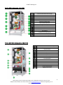
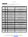
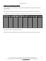
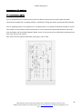
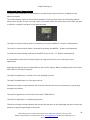
© MHG Heating Ltd Installation and Operating Manual for the ProCon MCS 320 -2150kW Floor Standing Gas Condensing Boilers 1 MHG Heating Ltd Unit 4 Epsom Downs Metro Centre, Waterfield, Tadworth, Surrey KT20 5LR Telephone 08456 448802 Fax 08456 448803 Email [email protected] Web www.mhgheating.co.uk 020315 Draft © MHG Heating Ltd Section Page Appliance Type 3 ProCon MCSS 4 Installation Regulations and Requirements 5 Appliance Warranties Supplied Components 6 Dimensions 7 Installation Clearances and Mounting Information 10 Delivery and Mobility 11 Case Removal 11 Technical Data 12 Load Loss on Water Input Side Curve (DT=20) 15 Pressure Relief Valve 17 Electrical Connections 18 Internal Wiring Diagram 19 Wiring Diagram Legend 24 Hydraulic and Wiring Guide Single Unit Option 1 (Heating Only) 25 Two Boiler Cascade Option 2 (heating Only) 26 Hydraulic and Wiring Guide Single Unit Option 3 (Heating & HWS) 27 Hydraulic and Wiring Guide Single Unit Option 4 (Heating Multi Zone & HWS) 28 Three Boiler Cascade Hidro Units Option 1 (Heating Only) 29 Three Boiler Cascade Hidro Units Option 2 (Heating & HWS) 30 Three Boiler Cascade Hidro Units Option 3 (Heating Multi Zone & HWS) 31 Theta Cascade Manager 32 Theta Electrical Connections 33 Fluing Options 34 Single Unit Flue Options (Internal/External) 35 Ventilation and Flue Terminal Positioning Guide (BS5440-1:2008, BS5440-2:2009, BS6644:2011 & IGE/UP/10 (ed3)) 36 Filling The System 39 Expansion Vessel 40 Appliance Controls 42 Appliance Fault Codes 43 NG/LPG – LPG/NG Conversion Procedure 44 Commissioning The Appliance 45 Combustion System Commissioning 46 Routine Inspection and Servicing 48 Weather Compensation Slope 51 Programing a Replacement GFA Module Controller 52 User Information 56 Operational Diagram 57 Sensor Resistance Tables 61 Exploded Spares Diagram 62 2 MHG Heating Ltd Unit 4 Epsom Downs Metro Centre, Waterfield, Tadworth, Surrey KT20 5LR Telephone 08456 448802 Fax 08456 448803 Email [email protected] Web www.mhgheating.co.uk 020315 Draft © MHG Heating Ltd Appliance Type There are currently Five base boiler models in the range which are combined in cascades to provide a further seventeen boilers within the ProCon MCS range. ProCon MCS 210 ProCon MCS 260 ProCon MCS 320 ProCon MCS 400 ProCon MCS 535 Cascade Unit (Hidro) ProCon MCS 580 Hidro ProCon MCS 670 Hidro ProCon MCS 740 Hidro ProCon MCS 800 Hidro ProCon MCS 850 Hidro ProCon MCS 940 Hidro ProCon MCS 1000 Hidro ProCon MCS 1250 Hidro ProCon MCS 1320 Hidro ProCon MCS 1380 Hidro ProCon MCS 1450 Hidro ProCon MCS 1600 Hidro ProCon MCS 1800 Hidro ProCon MCS 1850 Hidro ProCon MCS 1920 Hidro ProCon MCS 2000 Hidro ProCon MCS 2150 Hidro The ProCon MCS range is designed to be applied to systems requiring direct on boiler weather compensated heating and priority hot water production via a separate high recovery calorifier/cylinder. The ProCon MCS range is supplied complete with weather proofed casings, allowing the units to be located externally to the building without the need for a purpose built structure Dedicated cascade controllers, communication adapters, hydraulic kits form part of the Hidro units. 3 MHG Heating Ltd Unit 4 Epsom Downs Metro Centre, Waterfield, Tadworth, Surrey KT20 5LR Telephone 08456 448802 Fax 08456 448803 Email [email protected] Web www.mhgheating.co.uk 020315 Draft © MHG Heating Ltd ProCon MCS Configuration. (210-535) 1 Stainless Steel Double Heat Exchanger 2 Manometer 3 Pressure Switch Maximum 4 Pump Differential Pressure Switch 5 Return Pipework 6 6bar Pressure Relief Valve. 7 Pressure Switch Minimum 8 High Head Pump 9 Thermometer 10 Flow Pipework 11 Limit Thermostat 12 Gas Pipework 13 Condensate Discharge Pipework 14 Low NOx Premix Burner 15 Weather Proof Casing. ProCon MCS Hidro Configuration. (580-2150) 1 Stainless Steel Double Heat Exchanger 2 Pump Differential Pressure Switch 3 High Head Pump 4 6bar Pressure Relief Valve. 5 Common Flow Pipework DN150 PN6 6 Common Return Pipework DN150 PN6 7 Common Gas Pipework DN65 PN16 8 Common Condensate Discharge Pipework DN50 9 Limit Thermostat 10 Thermometer 11 Manometer 12 Pressure Switch Maximum 13 Pressure Switch Minimum 14 Low NOx Premix Burner 15 Weather Proof Casing. 4 MHG Heating Ltd Unit 4 Epsom Downs Metro Centre, Waterfield, Tadworth, Surrey KT20 5LR Telephone 08456 448802 Fax 08456 448803 Email [email protected] Web www.mhgheating.co.uk 020315 Draft © MHG Heating Ltd Installation Regulations and Requirements The installation of ProCon MCS boilers must be in accordance with the relevant requirements of Gas Safety (Installation & Use) Regulations 1994, Health & Safety at Work Act, Building Regulations, IEE Regulations, Construction (Design & Management) Regulations 1994, Local Authority Bye-Laws, National, Fire Regulations and Insurance Company requirements. The following Codes of Practice are also applicable:BS 5440-1: 2008 Installation of flues and ventilation for gas appliances of rated input not exceeding 70 kW net (1st, 2nd and 3rd family gases). Part 1: Specification for the installation of flues. BS 5440-2: 2009 Installation of flues and ventilation for gas appliances of rated input not exceeding 70 kW net (1st, 2nd and 3rd family gases). Part 2: Specification for installation and maintenance of ventilation for gas appliances. BS 5449: 1990 Specification for forced circulation hot water central heating systems for domestic premises. BS 6644: 2011 Specification for gas fired hot water boilers of rated inputs between 70kW (net) and 1.8MW(net) (2nd and 3rd family gases). BS 6798: 1987 Specification for installation of gas fired hot water boilers of rated input not exceeding 60 kW. BS 6880: 1988 Code of Practice for low temperature hot water heating systems of output greater than 45kW. Parts 1, 2 & 3. BS 6891: 1988 Specification for installation of low pressure gas pipework of up to 28mm (R1) in domestic premises (2nd family gases) BS 7593: 1992 Code of Practice for treatment of water in domestic hot water central heating systems. BS 7671: 1992 Requirements for electrical installations. IEE Wiring Regulations. Sixteenth edition. CISBE Guide reference sections B7, B11 and B13. CP342 Part 2: 1974 Code of Practice for centralized hot water supply. GE/UP/2 Gas installation pipework, boosters and compressors on industrial and commercial premises. IGE/UP/4 Commissioning of gas fired plant on industrial and commercial premises IGE/UP/10 Installation of gas appliances in industrial and commercial premises. Part 1: Flued appliances. And any addition prevailing regulation and or code of practice not detailed above. 5 MHG Heating Ltd Unit 4 Epsom Downs Metro Centre, Waterfield, Tadworth, Surrey KT20 5LR Telephone 08456 448802 Fax 08456 448803 Email [email protected] Web www.mhgheating.co.uk 020315 Draft © MHG Heating Ltd Appliance Warranties All MHG appliances enjoy a full 24 month warranty as detailed in our terms and conditions. The guarantee period shall begin on the day of commissioning, or within 3 months after delivery has been made. The customer shall only be able to claim against MHG under guarantee if the commissioning of the object of delivery has been carried out by MHG staff or the authorized supplier. Only if the customer has followed MHG's instructions relating to the treatment and maintenance of the object of delivery, and if no replacement parts of outside origin have been fitted. Parts subject to wear such as ignition electrodes, seals etc. are strictly excluded from the guarantee. In addition to the above warranties, the Primary Heat Exchangers carry a 60 month guarantee against manufacturing or material defect. Supplied Components All MCS units are test fired prior to dispatch. Due to shipping/handling issues the Hidro units are dismantled prior to shipping. The interconnecting power and cascade wirings and plugs are shipped within the master unit packaging. The Theta Cascade Controller is supplied with the following sensors: Common Flow sensor * Must be installed* Outside air sensor (Optional, required to activate direct on boiler weather compensation) HWS Sensor (Optional, A volt free enable can be used.)(A parameter adjustment will be required.) Mixed Zone 1 Flow Sensor (Optional) Mixed Zone 2 Flow Sensor (Optional) 6 MHG Heating Ltd Unit 4 Epsom Downs Metro Centre, Waterfield, Tadworth, Surrey KT20 5LR Telephone 08456 448802 Fax 08456 448803 Email [email protected] Web www.mhgheating.co.uk 020315 Draft © MHG Heating Ltd Dimensions ProCon MCS 320 (210 & 260 for use in Hidro Cascade units only) Manifold Connection Dimensions 1 System Delivery G 2”1/2 Male 2 System Return MCS 210 G 2”1/2 Male 3 System Return MCS 260 G 2”1/2 Male 4 System Return MCS 320 G 2”1/2 Male 5 Gas Inlet 210/260 G 1”1/2 Male 6 Gas Inlet320 G 1”1/2 Male 7 3 Way Water Outlet Valve G 1”1/2 Male 8 Condensate Discharge Ø25 9 Relief Valve Discharge G1”1/2 Male 10 Fume Discharge Ø=150 Female ProCon MCS 400 and 535 Manifold Connection Dimensions 1 System Delivery G 2”1/2 Male 2 System Return MCS 400 G 2”1/2 Male 3 System Return MCS 535 G 2”1/2 Male 4 Gas Inlet G 1”1/2 Male 5 3 Way Water Outlet Valve G 1”1/2 Male 6 Condensate Discharge Ø25 7 Relief Valve Discharge G1”1/2 Male 8 Fume Discharge Ø=180 Female 7 MHG Heating Ltd Unit 4 Epsom Downs Metro Centre, Waterfield, Tadworth, Surrey KT20 5LR Telephone 08456 448802 Fax 08456 448803 Email [email protected] Web www.mhgheating.co.uk 020315 Draft © MHG Heating Ltd ProCon MCS Hidro Units ProCon MCS 320 Hidro (210 & 260 for use in Hidro Cascade units only) ProCon MCS 400 and 535 Hidro Item Description MI Flow Header Connection RI Return Header Connection SC Condensate Water Connection SF Flue Gas Spigot 8 MHG Heating Ltd Unit 4 Epsom Downs Metro Centre, Waterfield, Tadworth, Surrey KT20 5LR Telephone 08456 448802 Fax 08456 448803 Email [email protected] Web www.mhgheating.co.uk 020315 Draft © MHG Heating Ltd ProCon MCS Hidro Layouts A = 400kW and 535kW units B = 210kW, 260kW and 320kW Units 9 MHG Heating Ltd Unit 4 Epsom Downs Metro Centre, Waterfield, Tadworth, Surrey KT20 5LR Telephone 08456 448802 Fax 08456 448803 Email [email protected] Web www.mhgheating.co.uk 020315 Draft © MHG Heating Ltd Installation and Service Clearances ProCon MC 210, 260, 320, 400 & 535 ProCon MCS Hidro All models If these clearances cannot be achieved please contact MHG’s technical department for guidance. 10 MHG Heating Ltd Unit 4 Epsom Downs Metro Centre, Waterfield, Tadworth, Surrey KT20 5LR Telephone 08456 448802 Fax 08456 448803 Email [email protected] Web www.mhgheating.co.uk 020315 Draft © MHG Heating Ltd Delivery and Mobility All ProCon MCS’s are supplied fully tested and therefore may contain residual test water. The test water utilised contains additives that will help prevent the pump from sticking and other metals from oxidising. To maintain the structural integrity of the appliance the internal components should not be used during the lifting and positioning of the unit. All packaging materials should be disposed of in an environmentally way. Case Removal The MCS front case is removable and secured in place by four screw tight swizzle lugs. The MCS Hidro front case is hinged at the top and secured in place by four screw tight swizzle lugs. The Theta cascade controller is mounted in a clear fronted housing secured on the left or right of the unit. All other casing panels are secured in place with screw tight swizzle lugs. Weather Proof Casing Craning the Boiler. If the boiler is to be raised in to position via a crane, it is essential that the base of the unit and the components immediate inside are protected from damage by using correctly located strops please contact MHG’s technical department for guidance. 11 MHG Heating Ltd Unit 4 Epsom Downs Metro Centre, Waterfield, Tadworth, Surrey KT20 5LR Telephone 08456 448802 Fax 08456 448803 Email [email protected] Web www.mhgheating.co.uk 020315 Draft © MHG Heating Ltd Technical Data ProCon MCS 210 (Used in Hidro Cascade) 260 (Used in Hidro Cascade) Nominal Heating Capacity kW 20-200 25-250 Nominal Thermal Power (80/60°C) kW 19.52-195.2 24.45- 244.5 26.63-266.3 Nominal Thermal Power (50/30°C) kW 21.3-213.0 Thermal Efficiency at Max Output (80/60°C) % 97.6 97.8 Thermal Efficiency at 30% Output (50/30°C) % 105.3 105.3 Thermal Efficiency at Max Output (50/30°C) % 106.5 106.52 NOx Class 5 5 Gas Consumption G20 m3/h 2.12-21.16 2.65-26.46 Gas Consumption G30 Kg/h 1.58-15.77 1.97-19.72 Gas Consumption G31 Kg/h 1.55-15.54 1.94-19.42 Min/Max Working Pressure Bar 1/6 1/6 Number of Burners # 2 2 Water Content of Individual Heat X L 22 26 Water Content of Unit L 26.6 31.6 B23 B23 230V/1400 230V/1500 Equipment Type Power Supply/Power Empty Weight Kg 275 306 Dimension WxDxH Mm 775x1150x1552 775x1150x1552 Flue Gas Mass Flow Kg/h 33.7-337.2 42.1-421.4 Filled Weight Kg 320 351 Residual Flue Pressure Pa 100 100 Carbon Dioxide Concentration % 9.0 9.0 320 400 535 Nominal Heating Capacity ProCon MCS kW 30-300 38-380 50-500 580 Hidro 25-550 Nominal Thermal Power (80/60°C) kW 29.39-293.9 37.3-373 49.1-491 24.45-538.4 Nominal Thermal Power (50/30°C) kW 31.95-319.5 40.47-404.7 53.25-532.5 24.45-585.8 Thermal Efficiency at Max Output (80/60°C) % 98.0 98.2 98.2 97.89 Thermal Efficiency at 30% Output (50/30°C) % 105.3 105.3 105.3 105.3 Thermal Efficiency at Max Output (50/30°C) % 106.5 106.5 106.5 105.51 5 5 5 5 Gas Consumption G20 m3/h 3.17-31.75 4.02-4021 5.29-52.91 2.65-58.21 Gas Consumption G30 Kg/h 3.37-23.66 3.00-29.97 3.94-39.43 1.97-43.38 NOx Class Gas Consumption G31 Kg/h 2.33-23.31 2.95-29.52 3.88-38.84 1.94-42.73 Min/Max Working Pressure Bar 1/6 1/6 1/6 1/6 Number of Burners # 2 2 2 4 Water Content of Individual Heat X L 30 39 55 56 Water Content of Unit L 36.7 46.7 63.8 132.3 Equipment Type B23 B23 B23 B23 Power Supply/Power 230V/1750 230V/1900 230V/2000 230V/3250 Empty Weight Kg 361 366 409 1000 Dimension WxDxH Mm 775x1150x1552 775x1150x1552 775x1150x1552 1550x1150x1552 Flue Gas Mass Flow Kg/h 50.6-505.7 64.1-640.6 84.3-842.9 42.1-927.1 Filled Weight Kg 361 366 409 1000 Residual Flue Pressure Pa 100 100 100 100 Carbon Dioxide Concentration % 9.0 9.0 9.0 9.0 12 MHG Heating Ltd Unit 4 Epsom Downs Metro Centre, Waterfield, Tadworth, Surrey KT20 5LR Telephone 08456 448802 Fax 08456 448803 Email [email protected] Web www.mhgheating.co.uk 020315 Draft © MHG Heating Ltd 670 Hidro 740 Hidro 800 Hidro Nominal Heating Capacity ProCon MCS kW 25-630 20-700 25-750 30-800 Nominal Thermal Power (80/60°C) kW 24.45-617.5 19.52-686.2 24.45-735.5 29.39-784.9 Nominal Thermal Power (50/30°C) kW 26.63-671 21.3-745.5 26.63-798.8 31.95-852 Thermal Efficiency at Max Output (80/60°C) % 98.02 98.03 98.06 98.11 Thermal Efficiency at 30% Output (50/30°C) % 105.3 105.3 105.3 105.3 Thermal Efficiency at Max Output (50/30°C) % 106.5 106.5 106.5 106.51 5 5 5 5 Gas Consumption G20 m3/h 2.65-66.67 2.12-74.07 2.65-79.37 3.17-84.66 Gas Consumption G30 Kg/h 1.97-49.69 1.58-55.2 1.97-59.15 2.37-63.09 Gas Consumption G31 Kg/h 1.94-48.94 1.55-54.38 1.94-58.26 2.33-62.15 Min/Max Working Pressure Bar 1/6 1/6 1/6 1/6 Number of Burners # 4 4 4 4 Water Content of Individual Heat X L 65 77 81 85 Water Content of Unit L 164.5 NOx Class 850 Hidro 142.3 154.4 159.4 Equipment Type B23 B23 B23 B23 Power Supply/Power 230V/3400 230V/3400 230V/3500 230V/3750 Empty Weight Kg 1032 104 1075 1085 Dimension WxDxH Mm 1550x1150x1552 1550x1150x1552 1550x1150x1552 1550x1150x1552 Flue Gas Mass Flow Kg/h 42.1-1062 33.7-1180.1 42.1-1264.3 50.6-1348.6 Residual Flue Pressure Pa 100 100 100 100 Carbon Dioxide Concentration % 9.0 9.0 9.0 9.0 1320 Hidro 940 Hidro 1000 Hidro 1250 Hidro Nominal Heating Capacity ProCon MCS kW 38-880 50-1000 25-1200 25-1250 Nominal Thermal Power (80/60°C) kW 37.3-864 49.1-982 19.52-1177.2 24.45-12226.5 Nominal Thermal Power (50/30°C) kW 40.47-937.2 53.25-1065 21.3-1278 26.63-1331.3 Thermal Efficiency at Max Output (80/60°C) % 98.11 98.20 98.10 98.12 Thermal Efficiency at 30% Output (50/30°C) % 105.3 105.3 105.3 105.3 Thermal Efficiency at Max Output (50/30°C) % 106.5 106.5 106.5 106.5 5 5 5 5 4.02-93.12 5.29-105.82 2.12-126.98 2.65-132.28 NOx Class Gas Consumption G20 m3/h Gas Consumption G30 Kg/h 3-69.4 3.94-78.86 1.58-94.63 1.97-98.58 Gas Consumption G31 Kg/h 2.98-68.36 3.88-77.68 1.55-93.22 1.94-97.1 Min/Max Working Pressure Bar 1/6 1/6 1/6 1/6 Number of Burners # 4 4 4 4 Water Content of Individual Heat X L 94 110 132 136 Water Content of Unit L 255.2 174.5 191.6 250.2 Equipment Type B23 B23 B23 B23 Power Supply/Power 230V/3900 230V/4000 230V/5400 230V/5500 Empty Weight Kg 1117 1160 1624 1655 Dimension WxDxH Mm 1550x1150x1552 1550x1150x1552 1550x1150x1552 1550x1150x1552 Flue Gas Mass Flow Kg/h 64.1-1483.5 84.3-1685.8 33.7-2023 42.1-2107.2 Residual Flue Pressure Pa 100 100 100 100 Carbon Dioxide Concentration % 9.0 9.0 9.0 9.0 13 MHG Heating Ltd Unit 4 Epsom Downs Metro Centre, Waterfield, Tadworth, Surrey KT20 5LR Telephone 08456 448802 Fax 08456 448803 Email [email protected] Web www.mhgheating.co.uk 020315 Draft © MHG Heating Ltd 1380 Hidro 1450 Hidro 1600 Hidro Nominal Heating Capacity ProCon MCS kW 30-1300 38-1380 50-1500 20-1700 Nominal Thermal Power (80/60°C) kW 29.39-1275.9 37.3-1355 49.1-1473 1952.1668.2 Nominal Thermal Power (50/30°C) kW 31.95-1384.5 40.47-1469.7 53.25-1597.5 21.3-1810.5 Thermal Efficiency at Max Output (80/60°C) % 98.15 98.19 98.20 98.13 Thermal Efficiency at 30% Output (50/30°C) % 105.3 105.3 105.3 105.3 Thermal Efficiency at Max Output (50/30°C) % 106.5 106.5 106.5 106.5 5 5 5 5 4.02-146.03 5.29-158.73 2.12-179.89 NOx Class 1800 Hidro Gas Consumption G20 m3/h 3.17-137.57 Gas Consumption G30 Kg/h 3.37-102-52 3-108.83 3.94-118.29 1.58-134.06 Gas Consumption G31 Kg/h 2.33-100.89 2.95-107.2 3.88-116.52 1.55-132.06 Min/Max Working Pressure Bar 1/6 1/6 1/6 1/6 Number of Burners # 6 6 6 8 Water Content of Individual Heat X L 140 149 165 187 Water Content of Unit L 346 260.3 270.3 287.4 Equipment Type B23 B23 B23 B23 Power Supply/Power 230V/5750 230V/5900 230V/6000 230V/7400 Empty Weight Kg 1665 1697 1740 2204 Dimension WxDxH Mm 2325x1500x1552 2325x1500x1552 2325x1500x1552 3100x1500x1552 Flue Gas Mass Flow Kg/h 50.6-2191.5 64.1-2362.4 84.3-2528.7 33.7-2865.9 Residual Flue Pressure Pa 100 100 100 100 Carbon Dioxide Concentration % 9.0 9.0 9.0 9.0 2150 Hidro 1850 Hidro 1920 Hidro 2000 Hidro Nominal Heating Capacity ProCon MCS kW 25-1750 30-1800 38-1880 50-2000 Nominal Thermal Power (80/60°C) kW 24.45-1717.5 29.39-1766.9 37.3-1846 49.1-1964 Nominal Thermal Power (50/30°C) kW 26.63-1863.8 31.95-1917 40.47-2002.2 53.25-2130 Thermal Efficiency at Max Output (80/60°C) % 98.11 98.16 98.19 98.20 Thermal Efficiency at 30% Output (50/30°C) % 105.3 105.3 105.3 105.3 Thermal Efficiency at Max Output (50/30°C) % 106.5 106.5 106.5 106.5 5 5 5 5 4.02-198.94 5.29-211.64 NOx Class Gas Consumption G20 m3/h 2.65-185.19 3.17-1+0.48 Gas Consumption G30 Kg/h 1.97-198.01 2.37-141.95 3-148.26 3.94-157.72 Gas Consumption G31 Kg/h 1.94-135.94 2.33-139.73 2.95-146.04 3.88-155.36 Min/Max Working Pressure Bar 1/6 1/6 1/6 1/6 Number of Burners # 8 8 8 8 Water Content of Individual Heat X L 191 195 204 220 Water Content of Unit L 383.2 351 356.1 366.1 Equipment Type B23 B23 B23 B23 Power Supply/Power 230V/7500 230V/7750 230V/7900 230V/8000 Empty Weight Kg 2235 2204 2277 2320 Dimension WxDxH Mm 3100x1500x1552 3100x1500x1552 3100x1500x1552 3100x1500x1552 Flue Gas Mass Flow Kg/h 42.1-2950.1 50.6-3034.4 64.1-3169.3 84.3-3371.6 Residual Flue Pressure Pa 100 100 100 100 Carbon Dioxide Concentration % 9.0 9.0 9.0 9.0 14 MHG Heating Ltd Unit 4 Epsom Downs Metro Centre, Waterfield, Tadworth, Surrey KT20 5LR Telephone 08456 448802 Fax 08456 448803 Email [email protected] Web www.mhgheating.co.uk 020315 Draft © MHG Heating Ltd Load Loss on Water Input Side Curve (DT=20C) ProCon MCS210 (Hidro Use Only) ProCon MCS260 (Hidro Use Only) ProCon MCS320 15 MHG Heating Ltd Unit 4 Epsom Downs Metro Centre, Waterfield, Tadworth, Surrey KT20 5LR Telephone 08456 448802 Fax 08456 448803 Email [email protected] Web www.mhgheating.co.uk 020315 Draft © MHG Heating Ltd ProCon MCS400 ProCon MCS535 16 MHG Heating Ltd Unit 4 Epsom Downs Metro Centre, Waterfield, Tadworth, Surrey KT20 5LR Telephone 08456 448802 Fax 08456 448803 Email [email protected] Web www.mhgheating.co.uk 020315 Draft © MHG Heating Ltd Pressure (Safety) Relief Valve In accordance with the prevailing British Standard 5440/6644, the installer shall install as suitably sized Pressure (Safety) Relief Valve. The location of this valve is important with respect to the applied pressure of the boiler circulation pump, it is therefore recommended to locate the Pressure (Safety) Relief Valve on the flow pipe immediately adjacent to the boiler; furthermore, there must not be any means of isolation between the boiler and the Pressure (Safety) Relief Valve. A pressure Relief Valve has been supplied within the unit. Setting: 5.4bar Item # 60 17 MHG Heating Ltd Unit 4 Epsom Downs Metro Centre, Waterfield, Tadworth, Surrey KT20 5LR Telephone 08456 448802 Fax 08456 448803 Email [email protected] Web www.mhgheating.co.uk 020315 Draft © MHG Heating Ltd Electrical Connections Basic electrical connection for the ProCon MCS Legend Item Description Theta Cascade Manager Providing Access to Each Modules Controller Data Appliance and Module Power Isolators (Green) Lockout Indicator (Red) Providing central control of power to each appliance (pair of burners) K3 Relay Safety interlock relay K11Relay Cascade commination interlock relay Module Fuses 10 Amp Main Power Supply and transfer terminal rails Sensor, E-Bus Cascade, RS485 Cascade & Module Power Supply Plugs All power and communication leads are supplied reformed with colour coded plugs and leads cut to the correct length. All modules are assembled wired test fired then dismantle for shipping. 18 MHG Heating Ltd Unit 4 Epsom Downs Metro Centre, Waterfield, Tadworth, Surrey KT20 5LR Telephone 08456 448802 Fax 08456 448803 Email [email protected] Web www.mhgheating.co.uk 020315 Draft © MHG Heating Ltd Module GFA Controller Wiring Diagram 19 MHG Heating Ltd Unit 4 Epsom Downs Metro Centre, Waterfield, Tadworth, Surrey KT20 5LR Telephone 08456 448802 Fax 08456 448803 Email [email protected] Web www.mhgheating.co.uk 020315 Draft © MHG Heating Ltd Theta Cascade Wiring Diagram 20 MHG Heating Ltd Unit 4 Epsom Downs Metro Centre, Waterfield, Tadworth, Surrey KT20 5LR Telephone 08456 448802 Fax 08456 448803 Email [email protected] Web www.mhgheating.co.uk 020315 Draft © MHG Heating Ltd 21 MHG Heating Ltd Unit 4 Epsom Downs Metro Centre, Waterfield, Tadworth, Surrey KT20 5LR Telephone 08456 448802 Fax 08456 448803 Email [email protected] Web www.mhgheating.co.uk 020315 Draft © MHG Heating Ltd Theta Cascade Module Wiring Diagram 22 MHG Heating Ltd Unit 4 Epsom Downs Metro Centre, Waterfield, Tadworth, Surrey KT20 5LR Telephone 08456 448802 Fax 08456 448803 Email [email protected] Web www.mhgheating.co.uk 020315 Draft © MHG Heating Ltd 23 MHG Heating Ltd Unit 4 Epsom Downs Metro Centre, Waterfield, Tadworth, Surrey KT20 5LR Telephone 08456 448802 Fax 08456 448803 Email [email protected] Web www.mhgheating.co.uk 020315 Draft © MHG Heating Ltd Wiring Diagram Legend # Description Location # Description Location A0 Theta Cascade Controller Control S1 Module 1 Main Power Switch Control A1 Combustion Fan Control Voltage Module S2 Module 2 Main Power Switch Control A2 Not Used NA S3 Module 3 Main Power Switch Control A3 Flow and Return Sensors Module S4 Module 4 Main Power Switch Control A4 Control & Limit Thermostats Module SE Outside Air Sensor (AF) Control A5 Module to Module Internal Communication NA SG RCD Breaker A6 Gas Valve Module SPA1 Module Fan Damper Switch (Upper) A7 Ignition Transformer Module SPA2 Module Fan Damper Switch (Lower) Module T3 Common Flow Sensor Control Control Module Module A8 Pump A9 Pump Differential Switch Module T4 HWS Sensor / Volt Free Enable Control B1 Module Rectification Electrode (Upper) Module T5 Mixing Zone Flow Sensor Control B2 Module Rectification Electrode (Lower) Module T6 Mixing Zone Flow Sensor (Upper Module Only) (Upper Module Only) Control CB HWS Charging Pump (Supplied By Others) System TAc1 Module Ignition Transformer (Upper) Module CBT1 Mixing Zone 1 Pump (Supplied By Others) System TAc2 Module Ignition Transformer (Lower) Module CBT2 Mixing Zone 2 Pump (Supplied By Others) System TF1 Module Flue Thermal Fuse (Upper) Module CI Main Heating Circuit Pump System TF2 Module Flue Thermal Fuse (Lower) Module (Supplied By Others) CC1 Module 1 Pump Module TM1 Module Flow Sensor (Upper) Module CC2 Module 2 Pump Module TM2 Module Flow Sensor (Lower) Module CC3 Module 3 Pump Module TR1 Module Return Sensor (Upper) Module Module 4 Pump (Lower) Module Module TR2 Module Return Sensor EVG1 CC4 Gas Valve (Upper Module) Module TRS Module Limit Thermostat Module EVG2 Gas Valve (Lower Module) Module TSF1 Module Flue Gas Thermostat Module F0 Main 16 Amp Control TSM1 Module Control Thermostat (Upper) Module F1 Module 1 10 Amp Control TSM2 Module Control Thermostat (Lower) Module F2 Module 2 10 Amp Control VM1 Mixing Zone 1 Valve (Supplied By Others) F3 Module 3 10 Amp Control VM2 Mixing Zone 2 Valve (Supplied By Others) F4 Module 4 10 Amp Control X1 Main Terminal Board Control H0 Remote Lockout Lamp Control X15.1 HWS, Common Flow Sensors Plug Control H2 Lockout Lamp Control X15.2 Mixing Zone Sensors Plug Control (Optional Extra) Control X16 Power Supply (2 Pin, 1 Amp Max) Control (System Limit Controls) Control X20 Module Power Supply Plug Control (System Temperature Control) Control X21 System Safety Group Plug Control H22 K3 K11 Control Panel Light Lockout Auxiliary Relay Lockout Auxiliary Relay System System KA1 Module 1 Pump Contactor Module X22.. E-Bus Cascade Communication Plugs Control KA2 Module 2 Pump Contactor Module X23 Main Heating Circuit Pump Plug Control KA3 Module 3 Pump Contactor Module X23.1 Mixing Zone 1 Pump Plug Control KA4 Module 4 Pump Contactor Module X23.2 Mixing Zone 2 Pump Plug Control MP1 Module Pump Differential Pressure Switch Module X24 HWS Charging Pump Plug Control MV1 Module Combustion Fan Motor (Upper) Module X26.1 Mixing Zone 1 Valve Plug Control MV2 Module Combustion Fan Motor (Low) Module X26.2 Mixing Zone 2 Valve Plug Control Pm System Water Low Pressure Switch Module X30 RS485 Cascade Communication Plug Control PS System Water High Pressure Switch Module X31 Outside Air Sensor Plug Control PS01 Condensate Level Limit Pressure Switch Module Y1 Cascade Communication Terminals Module Control Z1 Filter Control R9 Anti-Sludge Sensor (Optional Extra) S0 Theta Controller Main Power Switch Control BK Black BU Blue RD Red BN Brown WH White GR Grey 24 MHG Heating Ltd Unit 4 Epsom Downs Metro Centre, Waterfield, Tadworth, Surrey KT20 5LR Telephone 08456 448802 Fax 08456 448803 Email [email protected] Web www.mhgheating.co.uk 020315 Draft © MHG Heating Ltd Hydraulic Design Single Unit (Option 1) Heating Only (Direct on Boiler Weather Compensation.) 25 MHG Heating Ltd Unit 4 Epsom Downs Metro Centre, Waterfield, Tadworth, Surrey KT20 5LR Telephone 08456 448802 Fax 08456 448803 Email [email protected] Web www.mhgheating.co.uk 020315 Draft © MHG Heating Ltd Hydraulic Design Single Units (Option 2) Heating Only (Direct on Boiler Weather Compensation.) 26 MHG Heating Ltd Unit 4 Epsom Downs Metro Centre, Waterfield, Tadworth, Surrey KT20 5LR Telephone 08456 448802 Fax 08456 448803 Email [email protected] Web www.mhgheating.co.uk 020315 Draft © MHG Heating Ltd Hydraulic Design Single Unit (Option 3) Heating & HWS 27 MHG Heating Ltd Unit 4 Epsom Downs Metro Centre, Waterfield, Tadworth, Surrey KT20 5LR Telephone 08456 448802 Fax 08456 448803 Email [email protected] Web www.mhgheating.co.uk 020315 Draft © MHG Heating Ltd Hydraulic Design Single Unit (Option 4) Heating Multi Zone & HWS 28 MHG Heating Ltd Unit 4 Epsom Downs Metro Centre, Waterfield, Tadworth, Surrey KT20 5LR Telephone 08456 448802 Fax 08456 448803 Email [email protected] Web www.mhgheating.co.uk 020315 Draft © MHG Heating Ltd Hydraulic Design Hidro Units (Option 1) Heating Only (Direct on Boiler Weather Compensation.) 29 MHG Heating Ltd Unit 4 Epsom Downs Metro Centre, Waterfield, Tadworth, Surrey KT20 5LR Telephone 08456 448802 Fax 08456 448803 Email [email protected] Web www.mhgheating.co.uk 020315 Draft © MHG Heating Ltd Hydraulic Design Hidro Units (Option 2) Heating & HWS 30 MHG Heating Ltd Unit 4 Epsom Downs Metro Centre, Waterfield, Tadworth, Surrey KT20 5LR Telephone 08456 448802 Fax 08456 448803 Email [email protected] Web www.mhgheating.co.uk 020315 Draft © MHG Heating Ltd Hydraulic Design Hidro Units (Option 3) Heating Multi Zone & HWS 31 MHG Heating Ltd Unit 4 Epsom Downs Metro Centre, Waterfield, Tadworth, Surrey KT20 5LR Telephone 08456 448802 Fax 08456 448803 Email [email protected] Web www.mhgheating.co.uk 020315 Draft © MHG Heating Ltd Theta Cascade Manager The Theta Cascade Manager can be used to control up to Four ProCon MCS Single or Hidro units. A Master Theta Cascade Manager can control up to four slave Theta controllers enabling extended control of up to Twenty ProCon MCS units. The unit is supplied in a dedicated housing and associated sensors. The Theta Cascade Controller can proved direct control of: Up to Four ProCon MCS. One Direct Heating Zone. (With Optional Room Unit. With or Without Direct on Boiler Compensation.) Two Variable Temperate (3 Way Mixing Valve) Zones. (With Optional Room Unit. With or Without Compensation.) Direct Hot Water Generation. Thermal Solar Input to Domestic Hot Water Generation. 0-10 Volt Drive response. Remote monitoring and adjustmet via The Internet (LAN) or Mobile Network (GSM) Please refer to the separate Theta Controller manual for guidance on parameter settings. A copy is supplied with the unit, is availible from the website or from MHG’s Technical Department. 32 MHG Heating Ltd Unit 4 Epsom Downs Metro Centre, Waterfield, Tadworth, Surrey KT20 5LR Telephone 08456 448802 Fax 08456 448803 Email [email protected] Web www.mhgheating.co.uk 020315 Draft © MHG Heating Ltd Theta Electrical Connections Legend # Terminals Plug Description HWS Primary Pump A1 ~ CB 5/N X 24 Theta Controller CBT1 / CBT2 9 / 15 X 23.1.2 Mixing Zone Pumps CI 3/N X 23 System Heating Pump CMI 37 / 38 / N ProCon MCS GFA Controller CSOL 11 / N SE 26 / 23 X 31 T3 27 / 23 X 15.1 Common Flow Sensor T4 28 / 23 X 15.1 HWS Sensor / Volt Free Enable T5 29 / 23 X 15.2 Mixing Circuit 1 Sensor T6 33 / 23 X 15.2 Mixing Circuit 2 Sensor T7 34 / 23 T8 35 / 23 VM1 / VM2 7 / 8 / 13/ 14 / N Solar Pump Outside Air Sensor Solar Collector Sensor Solar Buffer Sensor X 26.1.2 Mixing Circuit Mixing Valves X1 ~ Low Voltage Connections X2 21 / 22 230 Volt Input Connections X3 ~ 230 Volt Output Connections X4 ~ 230 Volt Output Connections 1-10 V 24 / 25 0 – 10 Volt Interface Module 33 MHG Heating Ltd Unit 4 Epsom Downs Metro Centre, Waterfield, Tadworth, Surrey KT20 5LR Telephone 08456 448802 Fax 08456 448803 Email [email protected] Web www.mhgheating.co.uk 020315 Draft © MHG Heating Ltd Fluing Options Please note that excessive resistance within the flue will lead to a reduction in the output of the appliance and induce operational faults. DN160 PPS Flue Components (Pa Resistances) MCS 1955mm Flue Extension TBC 955mm Flue Extension TBC 500mm Flue Extension TBC 87º Bend TBC 45º Bend TBC 30º Bend TBC DN200 PPS Flue Components (Pa Resistances) Exhaust Pipe Terminal TBC Air Pipe Terminal TBC 1955mm Flue Extension TBC 955mm Flue Extension TBC 500mm Flue Extension TBC 333mm Flue Extension TBC 87º Bend TBC 45º Bend TBC 30º Bend TBC When flues are installed with horizontal sections/portions a 30 fall back to the boiler must be maintained. This will not only ensure condensate removal preventing premature seal failure, but also prevent nuisance condensate dripping from a wall termination. Flexible Flue Options A range of DN160 flexible flue systems are available. 34 MHG Heating Ltd Unit 4 Epsom Downs Metro Centre, Waterfield, Tadworth, Surrey KT20 5LR Telephone 08456 448802 Fax 08456 448803 Email [email protected] Web www.mhgheating.co.uk 020315 Draft © MHG Heating Ltd Single Unit Flue Options Internal Boiler External Boiler 35 MHG Heating Ltd Unit 4 Epsom Downs Metro Centre, Waterfield, Tadworth, Surrey KT20 5LR Telephone 08456 448802 Fax 08456 448803 Email [email protected] Web www.mhgheating.co.uk 020315 Draft © MHG Heating Ltd Air Supply, Ventilation and Balance Flue Terminal Positioning Quick Reference Guide for; BS 5440-1:2008, BS 5440-2:2009, BS 6644:2011 & IGE/UP/10 (ed3) BS5440-2:2009. Installation and maintenance of flue and ventilation for gas appliances of rated input not exceeding 70 kW net (1st 2nd & 3rd family gases) Open Flued Appliances Installed within a Room (Natural ventilation requirements direct to Outside Air) Total rated net input not in excess of (70 kW – 7 kW) x 5cm2 = Ventilation opening free area Open Flued Appliances Installed within a compartment (Natural ventilation requirements) Ventilation to room or internal space (The internal space ventilated into must be ventilated as detailed Ventilation direct to outside air Ventilation route above to outside air) Grille Location 10 cm2 20 cm2 High Level (Free Area/kW) Low Level (Free Area/kW) 5 cm2 10 cm2 Balanced Flued Appliances Installed within an Enclosure (Natural ventilation requirements) Ventilation route Ventilation to room or internal space Ventilation direct to outside air 10 cm2 10 cm2 5 cm2 5 cm2 Grille Location High Level (Free Area/kW) Low Level (Free Area/kW) Document Intended for quick guidance only. Absolute guidance must be sought from BS5440 2:2009 directly For BS 6644 and IGE UP 10 Installations the ventilation openings might need to be increased if the following air temperatures are exceeded. (@150C Ambient) High-Level (100mm Below Ceiling Level) Mid-level (1500mm Flow Floor Level) Low-Level (100mm Above Floor Level) 42C 32C 25C As a guide, reduction of air temperature may be achieved by increasing the inlet and outlet air supply by 0.15 m3/h or 0.2 cm2/kW of net heat input per 0C of temperature reduction required BS6644:2011 Specification for the Installation of gas-fired hot water boilers of rated inputs between 70 kW (net) and 1.8 MW (net) (2nd and 3rd family gases) Open Flued Appliances Installed within an Enclosure (Natural ventilation requirements direct to Outside Air) System Type & Heating &/or HWS Operation Heating &/or HWS Operation Heating &/or HWS Operation Operational Time < 50% time operation during > 50% < 75% time operation > 75% time operation during summer months during summer months summer months Grille Location High Level (Free Area/kW) Low Level (Free Area/kW) 5 cm2 10 cm2 6 cm2 11 cm2 7 cm2 12cm2 Open Flued Appliances Installed within a Boiler Room (Natural ventilation requirements direct to Outside Air) System Type & Heating &/or HWS Operation Heating &/or HWS Operation Heating &/or HWS Operation Operational Time < 50% time operation during > 50% < 75% time operation > 75% time operation during summer months (Biomass/Solid Fuel during summer months summer months Boiler Additional Free Area) Grille Location High Level (Free Area/kW) Low Level (Free Area/kW) 2 (Biomass/Solid Fuel Boiler Additional Free Area) 2 2 2 cm (3 cm ) 4 cm2 (6 cm2) 2 3 cm (4 cm ) 5 cm2 (7 cm2) (Biomass/Solid Fuel Boiler Additional Free Area) 4 cm2 (5 cm2) 6 cm2 (8 cm2) Balanced Flued Appliances Installed within an Enclosure (Natural ventilation requirements direct to Outside Air) System Type & Heating &/or HWS Operation Heating &/or HWS Operation Heating &/or HWS Operation Operational Time < 50% time operation during > 50% < 75% time operation > 75% time operation during summer months during summer months summer months Grille Location High Level (Free Area/kW) Low Level (Free Area/kW) 5 cm2 5 cm2 5 cm2 5 cm2 5 cm2 5 cm2 36 MHG Heating Ltd Unit 4 Epsom Downs Metro Centre, Waterfield, Tadworth, Surrey KT20 5LR Telephone 08456 448802 Fax 08456 448803 Email [email protected] Web www.mhgheating.co.uk 020315 Draft © MHG Heating Ltd Balanced Flued Appliances Installed within an Enclosure (Natural ventilation requirements to a room or internal space) System Type & Heating &/or HWS Operation Heating &/or HWS Operation Heating &/or HWS Operation Operational Time < 50% time operation during > 50% < 75% time operation > 75% time operation during summer months during summer months summer months Grille Location High Level (Free Area/kW) Low Level (Free Area/kW) 10 cm2 10 cm2 10 cm2 10 cm2 10 cm2 10 cm2 Balanced Flued Appliances Installed within a Boiler Room (Natural ventilation requirements direct to Outside Air) System Type & Heating &/or HWS Operation Heating &/or HWS Operation Heating &/or HWS Operation Operational Time < 50% time operation during > 50% < 75% time operation > 75% time operation during summer months during summer months summer months Grille Location High Level (Free Area/kW) Low Level (Free Area/kW) 2 cm2 2 cm2 3 cm2 3 cm2 4 cm2 4 cm2 Document Intended for quick guidance only. Absolute guidance must be sought from BS6644 : 2011 directly. Open Flued Appliances Installed with a Draught Diverter (Mechanical ventilation flow rate requirements direct to Outside Air) System Type & Operational Time Heating &/or HWS Operation < 50% time operation during summer months Heating &/or HWS Operation > 50% < 75% time operation during summer months Heating &/or HWS Operation > 75% time operation during summer months 2.07 +/- 0.18 (m3/h/kW) 2.07 +/- 0.18 (m3/h/kW) 2.07 +/- 0.18 (m3/h/kW) 2.8 (m3/h/kW) 3.52 (m3/h/kW) 4.24 (m3/h/kW) Grille Location High Level Extract (Difference Between Inlet and Extract Air) Low Level Inlet Open Flued Appliances Installed without a Draught Diverter (With or without stabilizers) (Mechanical ventilation flow rate requirements direct to Outside Air) System Type & Operational Time Heating &/or HWS Operation < 50% time operation during summer months Heating &/or HWS Operation > 50% < 75% time operation during summer months Heating &/or HWS Operation > 75% time operation during summer months 1.35 +/- 0.18 (m3/h/kW) 1.35 +/- 0.18 (m3/h/kW) 1.35 +/- 0.18 (m3/h/kW) 2.6 (m3/h/kW) 3.32 (m3/h/kW) 4.04 (m3/h/kW) Grille Location High Level Extract (Difference Between Inlet and Extract Air) Low Level Inlet Where high level/discharge openings are not mechanically assisted, the free area must be calculated as detailed above (Open Flued Appliances Installed within a Boiler Room (Natural ventilation requirements direct to Outside Air) All air inlet and extract fans must be fitted with automatic controls (interlocks) causing safety shut-down or lockout of the installed gas burning appliances in the event of an inlet or extract air flow failure Document Intended for quick guidance only. Absolute guidance must be sought from BS6644:2011 directly 37 MHG Heating Ltd Unit 4 Epsom Downs Metro Centre, Waterfield, Tadworth, Surrey KT20 5LR Telephone 08456 448802 Fax 08456 448803 Email [email protected] Web www.mhgheating.co.uk 020315 Draft © MHG Heating Ltd IGE/UP/10 Part 1 Edition 3 Installation of gas appliances in industrial and commercial premises Guidance for Boiler installations with Inputs in Excess of 1.8 MW net.(2nd and 3rd family gases) Open Flued Appliances Installed within an Enclosure (Natural ventilation requirements direct to Outside Air) System Type & Heating &/or HWS Operation Heating &/or HWS Operation Heating &/or HWS Operation Operational Time < 50% time operation during > 50% < 75% time operation > 75% time operation during summer months during summer months summer months Grille Location 5 cm2 10 cm2 High Level (Free Area/kW) Low Level (Free Area/kW) 6 cm2 11 cm2 7 cm2 12cm2 Room Sealed Appliances Installed within an Enclosure (Natural ventilation requirements direct to Outside Air) System Type & Heating &/or HWS Operation Heating &/or HWS Operation Heating &/or HWS Operation Operational Time < 50% time operation during > 50% < 75% time operation > 75% time operation during summer months during summer months summer months Grille Location 5 cm2 5 cm2 High Level (Free Area/kW) Low Level (Free Area/kW) 6 cm2 6 cm2 7 cm2 7 cm2 Room Sealed Appliances Installed within an Enclosure (Natural ventilation requirements Via an internal Space) System Type & Heating &/or HWS Operation Heating &/or HWS Operation Heating &/or HWS Operation Operational Time < 50% time operation during > 50% < 75% time operation > 75% time operation during summer months during summer months summer months Grille Location 10 cm2 10 cm2 High Level (Free Area/kW) Low Level (Free Area/kW) 11cm2 11cm2 12 cm2 12 cm2 Open Flued Appliances Installed within a Boiler Room (Natural ventilation requirements direct to Outside Air) System Type & Heating &/or HWS Operation Heating &/or HWS Operation Heating &/or HWS Operation Operational Time < 50% time operation during > 50% < 75% time operation > 75% time operation during summer months (Biomass/Solid Fuel during summer months summer months Grille Location High Level (Free Area/kW) Low Level (Free Area/kW) Boiler Additional Free Area) (Biomass/Solid Fuel Boiler Additional Free Area) (Biomass/Solid Fuel Boiler Additional Free Area) 2 cm2 (3 cm2) 4 cm2 (6 cm2) 3 cm2 (4 cm2) 5 cm2 (7 cm2) 4 cm2 (5 cm2) 6 cm2 (8 cm2) 1. For lighter than air gases where high and low level ventilation is not practicable and the volume of the space is equal to or greater than 1m3 per 2kW total net input, it is permitted to install 6cm2 per kW of total ventilation at high level only provided more than one ventilator is fitted. This is not permitted for heavier than air gasses 2. For lighter than air gases where the plant room does not exceed 1m3 per 2kW total net heat input, ducting of ventilation air to low level without mechanical assistance is not recommended Open Flued Appliances. Modern low radiation losses and low excess air burners (Mechanical ventilation flow rate requirements direct to Outside Air) System Type & Operational Time Heating &/or HWS Operation < 50% time operation during summer months Heating &/or HWS Operation > 50% < 75% time operation during summer months Heating &/or HWS Operation > 75% time operation during summer months Grille Location Appliances with draught diverters High Level Extract (Difference Between Inlet and Extract Air) Low Level Inlet 3 2.07 +/- 0.18 (m /h/kW) 2.07 +/- 0.18 (m3/h/kW) 2.07 +/- 0.18 (m3/h/kW) 2.8 (m3/h/kW) 3.52 (m3/h/kW) 4.24 (m3/h/kW) Appliances without draught diverters with or without draught stabilisers High Level Extract (Difference Between Inlet and Extract Air) Low Level Inlet 1.35 +/- 0.18 (m3/h/kW) 1.35 +/- 0.18 (m3/h/kW) 2.6 (m3/h/kW) 3.32 (m3/h/kW) Where high level/discharge openings are not mechanically assisted, the free area must be calculated at 2 1.35 +/- 0.18 (m3/h/kW) 4.04 (m3/h/kW) cm 2/kW net input All air inlet and extract fans must be fitted with automatic controls (interlocks) causing safety shut-down or lockout of the installed gas burning appliances in the event of an inlet or extract air flow failure Document Intended for quick guidance only. Absolute guidance must be sought from IGE/UP/10 Edition 3 directly 38 MHG Heating Ltd Unit 4 Epsom Downs Metro Centre, Waterfield, Tadworth, Surrey KT20 5LR Telephone 08456 448802 Fax 08456 448803 Email [email protected] Web www.mhgheating.co.uk 020315 Draft © MHG Heating Ltd Filling The System The Initial filling of a sealed heating system, and subsequent refilling, must be by a method that has been approved by the Water Regulation Advisory Scheme (WRAS) for that type of heating system. i.e. Domestic (In-House) Fluid Category 3 (C-3) Non Domestic (Other than In-House) Fluid Category 4 (C-4) For Category 3 systems, the approved method of filling must comprise of the following components in the arrangement shown; Control Valve incorporating a Double Check Valve on the Mains Cold Water pipework. Temporary Connecting Hose, which must be disconnected after use. Control Valve, on the heating system. For Category 4 systems, the approved method of filling must comprise of the following components in the arrangement shown; Control Valve. Strainer. Verifiable Backflow Device with Reduced Pressure Zone (RPZ Valve). Incorporating a ‘Type BA’ Air Gap. Tundish. Control Valve. Furthermore, in accordance with BS 6644: 2011 system with an input greater than 70kW (nett), an automatic water replenishment unit shall be installed to automatically replenish any lost or evaporated water. Please refer to BS 6644: 2011 for allowable water replenishment methods for use with sealed/pressurized heating systems. For information on a comprehensive range of pressurization units that comply with current British Standards and WRAS Regulations, please contact MHG Heating Ltd Sales. 39 MHG Heating Ltd Unit 4 Epsom Downs Metro Centre, Waterfield, Tadworth, Surrey KT20 5LR Telephone 08456 448802 Fax 08456 448803 Email [email protected] Web www.mhgheating.co.uk 020315 Draft © MHG Heating Ltd Expansion Vessel In accordance with BS 6644: 2011, WRAS Regulations, and Local Authority Water Regulations, as applicable, the installer shall install a suitably sized, and approved, Expansion Vessel to ensure that the water capacity of the system has ample expansion capacity. In complete compliance with BS6644:2011 a tapping is provided at the base of the boiler for the connection if a dedicated expansion vessel. The location of the expansion vessel shall only be isolatable from the system via a Lockable Type Service Valve, which shall be locked in the OPEN position, to prevent accidental isolation. Furthermore, a drain facility should be provided adjacent to the expansion vessel to aid the routine maintenance, overhaul, of the vessels Air Pressure setting. For information on a comprehensive range of expansion vessels that comply with current British Standards and WRAS Regulations, please contact MHG Heating Ltd Sales. System Water Quality Cleaning, flushing and water treatment must be carried out in accordance with the requirements of prevailing Building Regulations, British Standards, CIBSE Guides and related documents. The entire system/s MUST be thoroughly cleaned and flushed to remove debris, flux residues, etc. before opening the boiler isolation valves & flooding the boiler. Particular care must be taken where the ProCon boiler is being retro-fitted into an old/existing system, as system silt or magnetite can be very damaging to the new boiler. Consideration must be given to the installation of a MHG matched plate heat exchanger. Failing this a suitable straining/filtering device must be utilized to remove water borne debris. 40 MHG Heating Ltd Unit 4 Epsom Downs Metro Centre, Waterfield, Tadworth, Surrey KT20 5LR Telephone 08456 448802 Fax 08456 448803 Email [email protected] Web www.mhgheating.co.uk 020315 Draft © MHG Heating Ltd Following the cleansing and flushing the system MUST be dosed with a good quality water treatment to prevent corrosion and the formation of scale. FAILURE TO OBSERVE THESE REQUIREMENTS WILL RENDER THE WARRANTEE ON THE APPLIANCE VOID. Repeated draining planned or via leaks and refilling of the system, without replenishment of water treatment, must be avoided, as this is very damaging to the boiler and system components. Before activating the boiler following the initial installation or hydraulic remedial work on the system, allow the system to circulate for at least 2 hours with the boiler off. This will allow the system installed devices to capture/remove any water borne debris. (Micro Air Bubble & Impurity separators.) These devices must then be cleaned prior to commissioning the boiler. Additional device cleaning may be required during the first heating cycles. The system water must have the following characteristics to ensure the long term operation security of all boiler and system components. For specific guidance on water treatment, direct contact is advisable with:Betz Dearborn Limited Alpha-Fry Technologies (Fernox) (Sentiel) Cookson Electronics Foundry Lane Forsyth Road Widnes Woking Cheshire Surrey WA8 8UD GU21 5RZ Tel: 0151 424 5351 Tel: 0208 665 6666 Care With The Use of Solder Flux The ProCon MCS range has heat exchangers fabricated from 304L Stainless Steel. It is most important that the compatibility of any flux is checked with the supplier before use, and that any flux manufactures recommendations are strictly followed with regards to use in conjunction with Stainless Steel. If you are applying any of the ProCon Range to a system where the water quality cannot be cleansed or treated please consider installing a system separation plate heat exchanger to ensure absolute separation of the system water and the boiler water. Please refer to our website for further details on our matched brazed and gasketed plate heat exchanger range. 41 MHG Heating Ltd Unit 4 Epsom Downs Metro Centre, Waterfield, Tadworth, Surrey KT20 5LR Telephone 08456 448802 Fax 08456 448803 Email [email protected] Web www.mhgheating.co.uk 020315 Draft © MHG Heating Ltd Appliance Controls All appliance operational mode adjustments and settings are undertaken via the Theta Cascade Manager. The individual modules are not equipped with display panels. The controller can provide the following levels of information and adjustment. System Configuration Control Configuration Weather Compensation Configuration Temperature Configuration Speed Configuration Pump Configuration Historical Error Code Recovery To prevent functional parameters from being altered in error they are located behind a code. 42 MHG Heating Ltd Unit 4 Epsom Downs Metro Centre, Waterfield, Tadworth, Surrey KT20 5LR Telephone 08456 448802 Fax 08456 448803 Email [email protected] Web www.mhgheating.co.uk 020315 Draft © MHG Heating Ltd Appliance Fault Codes The display will read as _:__. The first digit identifies the boiler module at fault. The figures after the : are the fault codes detailed below. THETA Code Reset Description Effect The burner turns off and the circulating pump operates at maximum 3 Manual Intervention of the water safety speed. The lock-out disappears and the regulator resets when the thermostat temperature detected by the water safety thermostat falls below the temperature limit The ionization electrode does not detect a 4 Manual 5 Manual 6 Automatic Maximum delivery temperature exceeded The burner turns off and the circulating pump remains in operation 10 Manual Internal error The ignition of the burner is impeded 11 Manual 12 Automatic 14 Automatic 15 Automatic The flame control board goes into lock-out flame The ionization electrode does not detect The ignition is repeated the flame during operation of the burner The ionization electrode has detected a The ignition of the burner is impeded flame before the burner has turned on The delivery temperature sensor is The burner turns off interrupted or not working The return temperature sensor is The burner turns off interrupted or not working Protection for reaching the maximum Delta T permitted between delivery and The burner turns off and the circulating pump remains in operation return temperatures. 16 Automatic 20 Manual 21 Manual 24 Automatic/M anual withdraw heat from the system The ionization electrode detects the flame The ignition of the burner is impeded after the burner has turned off The combustion fan has broken and the The ignition of the burner is impeded Non Return valve has locked open Electric fan speed out of control The ignition is repeated when the fan speed is equal to +/-10% of that required or it attempts to start immediately by pressing the reset button The fume safety thermostat has been The burner turns off. The burner is reactivated using the RESET button interrupted after the temperature of the flue has fallen below the limit Automatic Combustion fan does not stop The ignition of the burner is impeded Manual The condensate syphon/drain is blocked The ignition of the burner is impeded 25 Manual 26 29 30 Manual 31 Manual 32 The circulating pump operates for 5 minutes at maximum speed to Antifreeze function Automatic The service settings are disturbed by The ignition of the burner is impeded electromagnetic interference Safety parameters errors The power supply is lower than 190Vac The ignition of the burner is impeded The burner ignition procedure waits until the supply voltage is greater than 200Vac The factory settings are disturbed by 38 Manual 40 Automatic 41 Automatic Presence of air in the circulating pump None 42 Automatic The circulating pump is blocked Circulating pump and burner turn off 43 Automatic Circulating pump wiring defective 56 57 Automatic Automatic The ignition of the burner is impeded electromagnetic interference An insufficient circulation of water has The burner turns off been detected after 10 seconds of start up Communication interrupted with one or more thermal modules Communication interrupted with one or more thermal module burners The burner turns off The ignition of the burner is impeded. The error received from the cascade eBus is not detected by the local eBus: this action leads to the blocking of the entire cascade The ignition of the burner is impeded. The error received from the local eBus is not detected by the local eBus: this action leads to the blocking of the entire cascade 43 MHG Heating Ltd Unit 4 Epsom Downs Metro Centre, Waterfield, Tadworth, Surrey KT20 5LR Telephone 08456 448802 Fax 08456 448803 Email [email protected] Web www.mhgheating.co.uk 020315 Draft © MHG Heating Ltd Converting The Appliance To Burn LPG (G31) Unless specified at the time of ordering the appliance/s will be supplied ready to operate on a Natural Gas (G20) fuel supply. The appliances data badge will indicate the type of fuel gas the modules have been set to operate with. If the appliance is required to operate on LPG the following controller adjustments must be undertaken. Boiler Type Module Range Fuel Injector CO2 % @ Fan Speed @ CO2 % @ Min Fan Speed @ Max Output Max Output Output Min Output MCS 210 10-100kW Nat Gas G20 None 9.10 5600 8.90 1700 MCS 210 10-100kW Propane G31 None 8.70 5600 8.55 1700 MCS 260 25-125kW Nat Gas G20 None 9.10 6600 8.90 1800 MCS 260 25-125kW Propane G31 None 8.70 6300 8.55 1800 MCS 320 30-150kW Nat Gas G20 None 9.10 5400 8.90 1500 MCS 320 30-150kW Propane G31 None 8.70 5200 8.55 1500 MCS 400 38-190kW Nat Gas G20 None 9.10 5500 8.90 1500 MCS 400 38-190kW Propane G31 None 8.70 5100 8.55 1500 MCS 535 50-249.5kW Nat Gas G20 None 9.10 5850 8.90 1667 MCS 535 50-249.5kW Propane G31 None 8.70 5535 8.55 1535 No mechanical restrictor / injectors are required. Please refer to the controller adjustment section to make the necessary alteration to the fan speeds. 44 MHG Heating Ltd Unit 4 Epsom Downs Metro Centre, Waterfield, Tadworth, Surrey KT20 5LR Telephone 08456 448802 Fax 08456 448803 Email [email protected] Web www.mhgheating.co.uk 020315 Draft © MHG Heating Ltd Commissioning The Appliance Pre-Commissioning Checks Prior to undertaking the commissioning of the unit please ensure that the system water has been cleansed and treated with a suitable inhibitor as detailed in Filling the System and System Water Quality. Prior to applying power to the appliance its circulation pump (10) should be bled and checked to ensure free rotation of the armature and the automatic air vent (a) should be opened and allowed to vent the heat exchanger and associated pipework. Better access to the pump can be achieved by removing the air duct from the fan inlet Venturi. Also ensure that the ignition electrodes spark gap is set to 4mm. 45 MHG Heating Ltd Unit 4 Epsom Downs Metro Centre, Waterfield, Tadworth, Surrey KT20 5LR Telephone 08456 448802 Fax 08456 448803 Email [email protected] Web www.mhgheating.co.uk 020315 Draft © MHG Heating Ltd Combustion System Commissioning To ensure correct operation of the combustion system the gas valve must be set at Maximum and Minimum outputs. The commissioning mode can be activated regardless of the operating status of the heating and how water control system. If zone or mixing valves are installed within the system ensure that these are open to allow for complete circulation of the generated heat. The High Fire commissioning mode is activated by pressing the MODE & + buttons simultaneously. The Low Fire commissioning mode is activated by pressing the MODE & - buttons simultaneously. To leave the commissioning mode press the RESET button or the + & - Button simultaneously. It is advisable to check the combustion figures on High and Low Fire prior to carrying out any adjustments. Adjusting the High Fire has a marked effect on the Low Fire figures. Where as adjusting the Low Fire has little effect on the High Fire figures. The High fire adjustment is carried out via red sheathed screw (4). The High Fire adjustment is a Gate type restrictor. Therefore turning the screw clockwise will close the Gate and thus restrict the quantity of gas passing through to the burner. The Low fire adjustment is carried out via the 4mm TORX head (2). The Low Fire adjustment is a diaphragm governor. Therefore turning the screw clockwise will increase the pressure on the diaphragm and thus increase the quantity of gas passing through to the burner. 46 MHG Heating Ltd Unit 4 Epsom Downs Metro Centre, Waterfield, Tadworth, Surrey KT20 5LR Telephone 08456 448802 Fax 08456 448803 Email [email protected] Web www.mhgheating.co.uk 020315 Draft © MHG Heating Ltd MCS 210 & 260 Valve Adjustment Legend 1. Gas Valve Assembly 2. High Fire Adjuster (Gate Type) 3. Low Fire Adjuster (Governor Type) (Under dust cap) (Make small adjustments only) MCS 320, 400 & 535 Valve Adjustment Legend 2. High Fire Adjuster (Gate Type) 3. Low Fire Adjuster (Governor Type) (Under dust cap) (Make small adjustments only) A flue gas analyser must be used to ensure that the correct combustion setting is achieved. This is undertaken by inserting the analyser’s probe in to plugged hole within the flue collector of the appliance or in the tapping in the flue immediately above the appliance if present. The combustion setting required for all ProCon appliances are as detailed in the following table. Boiler Type Module Range Fuel O2% at pmax CO2 % at Max Output O2% at pmin CO2 % at Min Output MCS 210 10-100kW Nat Gas G20 4.8 9.10 5.2 8.90 MCS 210 10-100kW Propane G31 5.5 8.70 5.8 8.55 MCS 260 25-125kW Nat Gas G20 4.8 9.10 5.2 8.90 MCS 260 25-125kW Propane G31 5.5 8.70 5.8 8.55 MCS 320 30-150kW Nat Gas G20 4.8 9.10 5.2 8.90 MCS 320 30-150kW Propane G31 5.5 8.70 5.8 8.55 MCS 400 38-190kW Nat Gas G20 4.8 9.10 5.2 8.90 MCS 400 38-190kW Propane G31 5.5 8.70 5.8 8.55 MCS 535 50-249.5kW Nat Gas G20 4.8 9.10 5.2 8.90 MCS 535 50-249.5kW Propane G31 5.5 8.70 5.8 8.55 47 MHG Heating Ltd Unit 4 Epsom Downs Metro Centre, Waterfield, Tadworth, Surrey KT20 5LR Telephone 08456 448802 Fax 08456 448803 Email [email protected] Web www.mhgheating.co.uk 020315 Draft © MHG Heating Ltd Fan Speeds and Modulation rates Module Ignition Rate Output of 1st Module During Ignition Fan Speed @ Max Output Fan Speed @ Min Output 5600 1700 55% 70% 5600 1700 55% 70% 6600 1800 55% 70% 6300 1800 55% 70% 5400 1500 55% 70% 5200 1500 55% 70% 5500 1500 55% 70% 5100 1500 55% 70% 5850 1667 55% 70% 5535 1535 55% 70% of 2nd Routine Inspection and Servicing As with all Gas Appliances, we would highly recommended that a competent heating engineer services the ProCon MCS, at least every 12 months. This is assuming a normal daily usage of 8 – 10 hours. If however the boiler is to be operated 24 hours a day, 7 days a week, we would recommend services every 6 months. If the Installer/Commissioning Engineer is unable to undertake the Routine Service Inspection, as detailed in the following, please contact the MHG Technical Department, who will be able to arrange the Routine Service Inspection to be undertaken. Routine Service Inspection Before commencing any service/maintenance work, the following tasks must be undertaken. a) Ask the end user about any problems with the operation of the boiler unit and note their comments. b) Check the water pressure of the installation. c) Remove the boiler casing and visually inspect all pipe and water joints for signs of leakage. d) Inspect the top of the casing and the top of the heat exchangers for signs of water leakage or ingress. e) Run the unit in Commissioning Mode HIGH FIRE; with the use of a flue gas analyzer record the CO 2 level. f) Run the unit in Commissioning Mode LOW FIRE; with the use of a flue gas analyzer record the CO2 level. g) Listen to the sound of the combustion fan. Utilizing the appliances fascia review the units Operating Error Codes, and note the recorded codes onto the Service Report. h) Undertake a System Water Analysis to check the concentration level of the Water Treatment, and note the level onto the Service Report. i) Check the flue route including the terminal position for conformity with prevailing regulations, and trim back any foliage that may be around the terminal. j) Check the plant room/compartment ventilation system for conformity with prevailing regulations. k) Check the Pressure (Safety) Relief Valve size, rating and orientation, for conformity with prevailing regulations. The results of the Inspections undertaken above must be acted upon, and all discrepancies should be recorded on the Service Report and brought to the Client / End User’s attention. Undertake any maintenance, and if necessary any preventative maintenance, that’s required. 48 MHG Heating Ltd Unit 4 Epsom Downs Metro Centre, Waterfield, Tadworth, Surrey KT20 5LR Telephone 08456 448802 Fax 08456 448803 Email [email protected] Web www.mhgheating.co.uk 020315 Draft © MHG Heating Ltd Routine Cleaning & Maintenance As part of the Routine Service Inspection, certain areas of the boiler need to the checked and cleaned as necessary. a) Turn the boiler OFF at the ON/OFF switch and electrically isolate the boiler by removing the plug or fuse from b) Turn off the gas at the boiler isolation tap, fitted by the installer, adjacent to the appliance. c) Remove the electrical connections, Gas valve balancing pipe and air inlet duct from the units fan assemble. d) Disconnect the earth lead, HT cap and Lead from the ignition electrodes. e) Loosen and disconnect the inlet gas supply form the gas valve. (Inspect and clean the inlet filter of the gas the boiler supply. valve.) f) Disassemble the burner by removing the six M6 nuts around the burner door, using a 10mm Spanner. Pull the burner forward and remove from the heat exchanger. Gently put to one side. g) Once access has been gained to the combustion chamber and lower heat exchanger, visually inspect the heat exchanger coils. It is usually only necessary to clean the lower section of the heat exchanger. If server deposits are found, the upper section of the heat exchanger should also be checked and cleaned, which may necessitate the removal of the heat exchanger from the boiler. If any coils appear to be significantly dis-coloured, then a blockage of either scale, magnetite, or general system debris has occurred which will have allowed excessive overheating to have occurred within the coil. If dis-colouration has occurred, then specialist de-scaling of the heat exchanger will be required, however, stress cracking may have occurred, and the heat exchanger may become porous following the de-scale works. h) If the heat exchanger has not suffered from dis-colouration, as ‘Item g’ above, then a Standard Service can be undertaken. Using a natural bristled brush ONLY, remove the worst of the mineral/debris build up. With the use of the dissolved ProCon Combustion Chamber Cleaning Granules, spray the solution onto the heat exchanger surface and leave for approximately 5 minutes. This will help to remove any stubborn mineral deposits and clear the condensate drain connections. Finally brush the heat exchanger whilst rinsing thoroughly with copious amounts of fresh water. ProCon Combustion Chamber Cleaning Granules are available from MHG Heating Ltd Spares Department. A STEEL OR PVC BRUSH MUST NOT BE USED TO CLEAN THE HEAT EXCHANGER. i) Following the cleaning of the Heat Exchangers, the condensate syphon must be flushed to ensure that all mineral deposits/debris that has been washed from the heat exchanger surface is correctly removed. Open the syphon cleaning point cap at the base of the boiler, with a suitable receptacle directly below to collect the syphon contents. Safely dispose of the contents of the syphon. Replace the receptacle below the cleaning point and poor 2 litres of clean tap water into the heat exchanger, which will drain through the cleaning point. Refit the cleaning point cap and poor one litre of clean tap water into the heat exchanger to ensure the syphon is re-flooded. Check the cleaning point cap for leaks. j) Visually check the burner surface for signs of damage and debris build-up. Remove any debris build up with compressed air. If excessive debris build-up is identified, the burner lance should be removed and the inner metal surface should be washed and cleaned. A BRUSH, OF ANY KIND, MUST NOT BE USED TO CLEAN THE BURNER SURFACE. If damage has occurred to the burner surface, the burner MUST be replaced. k) To ensure that the rectification circuit operates correctly the resistance between the burner and burner door must be check with a multi-meter to ensure that it is less than 1 Ohm (<1 Ohm.) 49 MHG Heating Ltd Unit 4 Epsom Downs Metro Centre, Waterfield, Tadworth, Surrey KT20 5LR Telephone 08456 448802 Fax 08456 448803 Email [email protected] Web www.mhgheating.co.uk 020315 Draft © MHG Heating Ltd l) Clean with abrasive material and inspect the ignition electrode. Replace if necessary. Adjust the spark gap to 4mm. m) Check the combustion fan blades for debris build-up. Remove any debris with a soft bristle brush or preferably compressed air. DO NOT TOUCH OR SPIN THE FAN BLADES WITH YOUR FINGERS AS THIS COULD AFFECT THE BALANCING OF THE FAN BLADES. n) Re-fit the Burners, in the reverse order of dismantling, ensure that all electrical connections are correctly and securely connected. o) Inspect all water joints. Any joints found to be leaking MUST be replaced. It is also advisable when replacing water joints to also change any adjacent joints at the same time. p) Inspect all gas joints with a suitable leak detection method. Any joints found to be leaking MUST be replaced. It is also advisable when replacing gas joints to also change any adjacent joints at the same time. q) Via the tappings on the boiler connector adapter, elbow or straight a flue gas recirculation check must be r) Drain and clean the condensate syphon assembly. Check the operation of the level pressure switch. s) If fitted inspect and clean the condensate neutralising tank, replenishing the neutralising granules as undertaken when the boiler is operating on high and low fire modes. required. Granules available from MHG Heating Ltd Spares Department. t) With the use of a suitable Flue Gas Analyser, check and adjust the combustion settings, as detailed in the previous commissioning section. u) Inspect the general condition of the flue system, including the termination, repair as necessary or advise on any remedial action as required. 50 MHG Heating Ltd Unit 4 Epsom Downs Metro Centre, Waterfield, Tadworth, Surrey KT20 5LR Telephone 08456 448802 Fax 08456 448803 Email [email protected] Web www.mhgheating.co.uk 020315 Draft © MHG Heating Ltd Weather Compensation Slope System Flow Temperature Outside Air Temperature 1 = Under Floor Heating 2 = Radiator Heating 3 = Convector Heating 51 MHG Heating Ltd Unit 4 Epsom Downs Metro Centre, Waterfield, Tadworth, Surrey KT20 5LR Telephone 08456 448802 Fax 08456 448803 Email [email protected] Web www.mhgheating.co.uk 020315 Draft © MHG Heating Ltd Programing a Replacement GFA Module Controller Replacement GFA Module controller are supplied for use in any location within the cascade. The GFA module control will require programming prior to re-commissioning the combustion. A cascade communication error message will be displayed if the following process is not undertaken. **Prior to undertaking any work with a PCB please earth yourself by touching a secure earth connection within the boiler.** 1. Check the build version of the Theta Controller. Data Badge on Rear of unit. This must be >E05. 2. Check the software version of the Theta Controller by switching the unit ON and pressing and holding the “I” Button. The version must be 20:03 V 3.3 or greater. 3. Electrically isolate the Theta Controller and all or the modules. Disconnect the module electrical connections. Dedicated plugs are used to prevent misapplication. 1, Locking Tab connectors. 2, BUS 1 Connectors, 3 GFA Controller Housing 52 MHG Heating Ltd Unit 4 Epsom Downs Metro Centre, Waterfield, Tadworth, Surrey KT20 5LR Telephone 08456 448802 Fax 08456 448803 Email [email protected] Web www.mhgheating.co.uk 020315 Draft © MHG Heating Ltd 4. Release the GFS controller from the DIN rail using a flat bladed screw driver. 5. Open the GFA controller housing using a flat bladed screw driver. 6. Install the GFA PCB within the existing GFA housing. 1, bottom housing 2, New GFA PCB 3, Top Housing. 7. Clip the new controller on to the DIN rail and reconnect the dedicated plug assemblies. Special attention needs to be paid to the JUMPER location and the connection of the BUS2 plug. This must be located between PIN 1 & 2 (Counted from the left) Each new controllers must now be allocated a cascade address via the Theta controllers. **This must take place one at a time!!!** Leave the X20 connected to the newly replaced GFA Module controller. All existing GFA Module controllers within the cascade must be disconnected from the power supply by removing all other Plug X20s 53 MHG Heating Ltd Unit 4 Epsom Downs Metro Centre, Waterfield, Tadworth, Surrey KT20 5LR Telephone 08456 448802 Fax 08456 448803 Email [email protected] Web www.mhgheating.co.uk 020315 Draft © MHG Heating Ltd Apply power to the new GFA module controller. Set the Theta Controller to STANDBY Press and hold the and buttons simultaneously for 3 seconds. 54 MHG Heating Ltd Unit 4 Epsom Downs Metro Centre, Waterfield, Tadworth, Surrey KT20 5LR Telephone 08456 448802 Fax 08456 448803 Email [email protected] Web www.mhgheating.co.uk 020315 Draft © MHG Heating Ltd 55 MHG Heating Ltd Unit 4 Epsom Downs Metro Centre, Waterfield, Tadworth, Surrey KT20 5LR Telephone 08456 448802 Fax 08456 448803 Email [email protected] Web www.mhgheating.co.uk 020315 Draft © MHG Heating Ltd User Information The ProCon’s display panel provides operational information and a means of adjusting the unit to provide the required level of heating and hot water generation. Following the powering up of the appliance a series of internal checks are undertaken, This can take a number of minutes. If the unit fails to operate and displays an error code please make a note of the code prior pressing the RESET button. If site support is required the noting of the error code will assist with the fault diagnosis and the provision of suitable replacement components if required. If the cause of the operational error has not been rectified the boiler will display a further error code following a period of up to 5 minutes during which time the unit is undergoing an internal diagnosis process. 56 MHG Heating Ltd Unit 4 Epsom Downs Metro Centre, Waterfield, Tadworth, Surrey KT20 5LR Telephone 08456 448802 Fax 08456 448803 Email [email protected] Web www.mhgheating.co.uk 020315 Draft © MHG Heating Ltd Operational Diagram ProCon MCS Legend Item Description MI Boiler Flow GAS Gas Inlet SC Condensate Outlet RI System Return 1 Combustion Fan 2 Air Gas Mixing Venturi 3 Heat Exchanger 4 Premix Burner 5 Flow Sensor NTC 1 6 Return Sensor NTC 2 7 Gas Valve 8 Automatic Air Vent 9 Boiler Pump 10 Minimum System water Pressure Switch 11 Pressure Relief Valve 12 Control Panel 15 Outside Air Sensor 16 Condensate Trap 17 Pressure Gauge 18 Tundish 19 Flue Gas Analyser Test Point 20 Flue Gas Thermostat 57 MHG Heating Ltd Unit 4 Epsom Downs Metro Centre, Waterfield, Tadworth, Surrey KT20 5LR Telephone 08456 448802 Fax 08456 448803 Email [email protected] Web www.mhgheating.co.uk 020315 Draft © MHG Heating Ltd Operational Diagram ProCon MCS Hidro Two Unit 58 MHG Heating Ltd Unit 4 Epsom Downs Metro Centre, Waterfield, Tadworth, Surrey KT20 5LR Telephone 08456 448802 Fax 08456 448803 Email [email protected] Web www.mhgheating.co.uk 020315 Draft © MHG Heating Ltd Operational Diagram ProCon MCS Hidro Three Unit 59 MHG Heating Ltd Unit 4 Epsom Downs Metro Centre, Waterfield, Tadworth, Surrey KT20 5LR Telephone 08456 448802 Fax 08456 448803 Email [email protected] Web www.mhgheating.co.uk 020315 Draft © MHG Heating Ltd Operational Diagram ProCon MCS Hidro Four Unit 60 MHG Heating Ltd Unit 4 Epsom Downs Metro Centre, Waterfield, Tadworth, Surrey KT20 5LR Telephone 08456 448802 Fax 08456 448803 Email [email protected] Web www.mhgheating.co.uk 020315 Draft © MHG Heating Ltd Sensor Resistance Table Outside Air Sensor Flow Sensors T(°C) R(kΩ) T(°C) R(kΩ) -20 1.383 10 1.783 -18 1.408 12 1.812 -16 1.434 14 1.840 -14 1.459 16 1.869 -12 1.485 18 1.898 -10 1.511 20 1.928 -8 1.537 25 2.002 -6 1.563 30 2.078 -4 1.590 35 2.155 -2 1.671 40 2.234 ±0 1.644 45 2.314 2 1.671 50 2.395 4 1.699 55 2.478 6 1.727 60 2.563 8 1.755 65 2.648 10 1.783 70 2.735 12 1.812 75 2.824 14 1.840 80 2.914 16 1.869 85 3.005 18 1.898 90 3.098 20 1.928 95 3.192 25 2.002 100 2.002 30 2.078 61 MHG Heating Ltd Unit 4 Epsom Downs Metro Centre, Waterfield, Tadworth, Surrey KT20 5LR Telephone 08456 448802 Fax 08456 448803 Email [email protected] Web www.mhgheating.co.uk 020315 Draft © MHG Heating Ltd Exploded Spares Diagram MCS 210 62 MHG Heating Ltd Unit 4 Epsom Downs Metro Centre, Waterfield, Tadworth, Surrey KT20 5LR Telephone 08456 448802 Fax 08456 448803 Email [email protected] Web www.mhgheating.co.uk 020315 Draft © MHG Heating Ltd Exploded Spares Diagram MCS260 63 MHG Heating Ltd Unit 4 Epsom Downs Metro Centre, Waterfield, Tadworth, Surrey KT20 5LR Telephone 08456 448802 Fax 08456 448803 Email [email protected] Web www.mhgheating.co.uk 020315 Draft © MHG Heating Ltd Exploded Spares Diagram MCS360 64 MHG Heating Ltd Unit 4 Epsom Downs Metro Centre, Waterfield, Tadworth, Surrey KT20 5LR Telephone 08456 448802 Fax 08456 448803 Email [email protected] Web www.mhgheating.co.uk 020315 Draft © MHG Heating Ltd Exploded Spares Diagram MCS400 65 MHG Heating Ltd Unit 4 Epsom Downs Metro Centre, Waterfield, Tadworth, Surrey KT20 5LR Telephone 08456 448802 Fax 08456 448803 Email [email protected] Web www.mhgheating.co.uk 020315 Draft © MHG Heating Ltd 66 MHG Heating Ltd Unit 4 Epsom Downs Metro Centre, Waterfield, Tadworth, Surrey KT20 5LR Telephone 08456 448802 Fax 08456 448803 Email [email protected] Web www.mhgheating.co.uk 020315 Draft © MHG Heating Ltd Exploded Spares Diagram MCS535 67 MHG Heating Ltd Unit 4 Epsom Downs Metro Centre, Waterfield, Tadworth, Surrey KT20 5LR Telephone 08456 448802 Fax 08456 448803 Email [email protected] Web www.mhgheating.co.uk 020315 Draft © MHG Heating Ltd Exploded Spares Diagram Control Panel All Models Exploded Spares Diagram Hidro 210 68 MHG Heating Ltd Unit 4 Epsom Downs Metro Centre, Waterfield, Tadworth, Surrey KT20 5LR Telephone 08456 448802 Fax 08456 448803 Email [email protected] Web www.mhgheating.co.uk 020315 Draft © MHG Heating Ltd Exploded Spares Diagram Hidro 260 Exploded Spares Diagram Hidro 320, 400 & 535 69 MHG Heating Ltd Unit 4 Epsom Downs Metro Centre, Waterfield, Tadworth, Surrey KT20 5LR Telephone 08456 448802 Fax 08456 448803 Email [email protected] Web www.mhgheating.co.uk 020315 Draft © MHG Heating Ltd Notes 70 MHG Heating Ltd Unit 4 Epsom Downs Metro Centre, Waterfield, Tadworth, Surrey KT20 5LR Telephone 08456 448802 Fax 08456 448803 Email [email protected] Web www.mhgheating.co.uk 020315 Draft