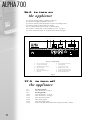
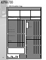
1
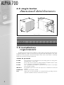
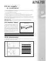
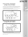
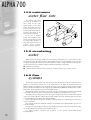
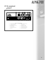
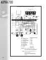
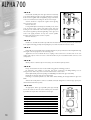
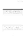
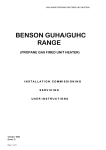
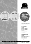
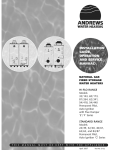
ALPHA70
CAST IRON SECTIONAL
OIL, GAS & DUAL FUEL BOILERS
SINGLE UNIT OUTPUTS 295kW - 640kW
I N S T R U C T I O N S F O R A S S E M B LY /
INSTALLATION, SERVICING & OPERATION
ALPHA 700
contents
page
section
3 . . . . . . . . . . .1.0
2.0
General Notes
Product Description
4 . . . . . . . . . . .3.0
Key Points
5 . . . . . . . . . . .4.0
5.0
Specification for Alpha 700
Delivery
6 . . . . . . . . . . .6.0
7.0
Single Boiler Dimensional Data/Clearances
Installation Requirements
7 . . . . . . . . . . .8.0
9.0
10.0
Air Supply & Ventilation
Boiler Base
Clearances
8 . . . . . . . . . .11.0
Technical Data
9 . . . . . . . . . .12.0
13.0
System Schematic Using Reverse/Return
System Schematic Using Diverter Valves
10 . . . . . . . . .14.0
15.0
16.0
Minimum Water Flow Rate
Circulating Water
Flue Systems
11 . . . . . . . . .17.0
Control Panel
12 . . . . . . . . .17.0
Standard Boiler Control Panel Electrical Diagram
13-17 . . . . . . .18.0
18 . . . . . . . . .19.0
System Connections
19 . . . . . . . . .20.0
21.0
22.0
Mounting The Burner
Controls
Commissioning Procedures
20 . . . . . . . . .23.0
24.0
Initial Lighting
Adjustment & Safety Checks
21 . . . . . . . . .25.0
Boiler Servicing
22 . . . . . . . . .26.0
27.0
To Turn On The Appliance
To Turn Off The Appliance
23 . . . . . . . . .28.0
Fault Finding
24-25 . . . . . . .29.0
2
Boiler Installation
Boiler Log
26 . . . . . . . . .30.0
Service Repair Record Sheet
27 . . . . . . . . .31.0
Spare Parts
ALPHA 700
1.0 general
notes
These instructions are intended to assist the installer, commissioning engineer, maintenance engineer
and user with the assembly, installation maintenance and operation of the Alpha 700 Series Cast Iron
Sectional Boilers and must be read in conjunction with the instructions supplied with the burner. Please
read this manual fully before commencing the installation of the boiler.
This manual must be handed to the appliance user following completion of the installation.
If the Alpha 700 boiler is to be gas fired, then the installer must be deemed to be competent in the
relevant areas of gas work involved and be Corgi Registered for those areas.
2.0 product
description
The Alpha 700 Series of cast iron boilers are engineered to the highest standards of design and
production quality, performance and reliability.
The range comprises nine models offering LTHW outputs from 295 to 640 kW. Each boiler is supplied
with a matched Natural gas, LPG, Oil or Dual Fuel Burner.
The boilers are supplied in kit form for on-site assembly, thus allowing greater ease of handling and
reduced difficulties where plant room access is restricted.
3
ALPHA 700
3.0 key
points
conformity with standards
All Alpha 700 series boilers are designed and manufactured in accordance with the
requirements of EN 303.1 and are supplied with burners certified to the relevant
standards.
Alpha 700 series boilers are CE approved and conform to all relevant standards and
requirements.
68AR139
quality
Alpha 700 burners are manufactured under a quality system in accordance with Quality Assurance
ISO 9001.
high output
The boiler heat exchanger has been designed around the turbo rotation principle of turbulent flow of
flue gases through the flueways giving excellent heat transfer properties. The Alpha 700 series provides
outputs from 295kW to 640kW, with the use of 8 through to 16 sections.
fuel options
Each boiler is supplied with a perfectly matched power flame burner. The user has freedom to choose
from natural gas, LPG or class D oil. With a quick burner changeover, or with the use of a dual fuel burner,
there is no need to be locked into any single fuel, allowing the use of the most economical fuel.
reduced emissions
The combustion chamber and flueways are of large volume and this, coupled with the principle of flue
gas flow employed and power flame combustion, significantly reduces un-burnt particles and harmful
oxides, protecting the environment from higher levels of damaging pollution.
built to last
The exceptional corrosion resistant properties of the casting material in conjunction with the unique
polygonal profile of the combustion chamber combine to create a boiler body that will withstand the
rigours of heavy duty. The combustion chamber walls are designed to allow convex flexing, giving the
inherent strength of resistance to mechanical and thermal movement.
reduced maintenance
The turbo rotational passage of the flue gases through the generous sized flueways ensures low
potential for fouling with combustion deposits. In addition, the entire front of the boiler body is a hinged
access door providing easy and generous access for cleaning and inspection, reducing maintenance time.
low standby losses
The use of burners with fully closing air inlet dampers, and a high standard of insulation, keeps standby
and maintenance losses to a minimum within the range 0.3 to 0.5%, conserving energy and reducing plant
room temperatures.
guarantee
Heat exchanger carries a five year guarantee against material or manufacturing defect.
4
ALPHA 700
4.0 specification
for Alpha 700
The three pass heat exchanger is constructed using high carbon content corrosion resistant cast iron
sections with turbo rotational flue passes and polygonal profile combustion chamber.
The assembled body is connected together using biconical nipples and full length tie rods. Gas tight
sealing of the sections, one to another, is achieved using ceramic fibre rope bedded into channels in the
casting faces.
The rear of the combustion chamber includes an anchored ceramic target wall. The combustion
chamber is fully water cooled and is spaced generously above floor level to ensure low boiler house floor
temperatures. The boiler is suitable for a maximum flow temperature of 95°C and a maximum working
pressure of 5.5 bar.
combustion chamber door
The combustion chamber door covers the entire front of the boiler body, providing uncompromised
access to the combustion chamber and horizontal flueways, allowing total front cleaning with the robust
cleaning tools provided. The door is hinged on both left and right hand sides giving freedom of choice for
handed opening without the need to move hinge positions. The door is heavily insulated with dense
ceramic fibre panels which reduces heat loss and thermal inertia.
insulation
The boiler body is insulated on all faces with a dense fibre-backed insulating blanket of 100mm
thickness.
casing
Each boiler is provided with a high quality rigidly attached stove enamelled casing.
control panel
Each boiler is supplied with a fully pre-wired top mounted control pod which incorporates high and low
fire control thermostats, manual reset high limit thermostat, water temperature thermometer, burner
on/off switch, pump on/off switch, high limit thermostat test button, high and low fire hours run counters,
fascia mounted fuse holder and lamps to indicate low fire, high fire, power on, high limit trip and burner
lockout. As an option, volt free contacts may be included to relay status information to a BMS or similar
remote monitoring panels.
5.0 delivery
item 1 Pallet(s) of boiler sections complete with accessories.
item 2 Pack of tie rods.
item 3 Carton containing casing and insulation.
item 4 Selected burner and burner accessories.
item 5 Carton containing control panel.
5
ALPHA 700
6.0 single boiler
dimensional data/clearances
430
1020
B
A
165
1765
1600
øD
1135
1410
530
C
555
102
Dimensions in millimetres
Models
Alpha 700
300
340
380
425
470
510
555
600
640
A - Overall Length - mm
1515
1650
1785
1920
2055
2190
2325
2460
2595
B - Casing Length
- mm
1360
1495
1630
1765
1900
2035
2170
2305
2440
C - Section Length - mm
1030
1165
1300
1435
1570
1705
1840
1975
2110
D - Flue Outlet Size - mm
300
300
300
300
300
300
300
300
300
Flow & Return Connection
DN100
DN100
DN100
DN100
DN100
DN100
DN100
DN100
DN100
7.0 installation
requirements
The Alpha 700 series boilers must be installed in accordance with (as appropriate) the requirement of
the Building Regulations, Health and Safety Executive Regulation PM5, IEE Regulations, Gas Safety
(Installation and Use) Regulation, National Water Bylaws, Clean Air Act Memorandum on Chimney
Heights and any Insurance Company requirements.
codes of practice
BS 6880
BS 5410
BS 6644
IGE/UP/2
CISBE Guide
LPG
6
Code of Practice for low temperature hot water heating systems for output greater
than 45kW, Parts 1, 2 and 3: 1988.
Part 2: 1978 - Code of Practice for oil firing installations of 44kW and above output
for space heating, hot water and steam supply purposes.
1991 - Specification for installation of gas fired hot water boilers of rated inputs
between 60kW and 2MW.
Gas Installation pipework, boosters and compressors on industrial and commercial
premises.
Reference sections B7, B11 and B13.
When boilers are fired with LPG, it is recommended that gas leakage detection
equipment is installed at low level, near the boiler or boilers.
ALPHA 700
8.0 air supply
& ventilation
An adequate supply of fresh air for combustion and ventilation of the boiler house must be supplied in
accordance with BS6644/BS5410 as appropriate.
The air supply should be achieved using:
a) Natural ventilation with low level and high level openings.
b) Using a fan to supply air to a low level opening with natural discharge through a high level opening.
c) Using a fan to supply air to a low level opening and a fan to extract air at a high level opening.
Where natural ventilation is used, suitable permanent openings connected directly to the outside air must
be provided. The openings should be fitted with grilles that cannot be easily blocked or flooded. The free
area of the grilles should be as follows:LOW LEVEL (inlet)
540cm2 plus 4.5cm2 per kW in excess of 60kW of total rated input.
HIGH LEVEL (outlet) 270cm2 plus 2.25cm2 per kW in excess of 60kW of total rated input.
9.0 boiler base
plinth details
≈10cms
Alpha boilers should be installed on a level
fireproof plinth with a minimum height of 100mm.
The plinth must be capable of supporting the
weight of the boiler/s when they are filled with
water. The front of the plinth can be level with, but
not extend beyond, the front of the boiler casing.
Depending on the make of burner selected, dual
fuel applications may require a higher plinth.
Details will be provided on request.
A
B
Plinth must be level and trowelled smooth.
Alpha 700
300
340
380
425
470
510
555
600
640
A cm
136
150
163
177
190
204
217
231
244
B cm
112
112
112
112
112
112
112
112
112
10.0 clearances
The dimensions shown below are required for proper access for assembly and maintenance. There is
no requirement for clearance above the boiler.
1000 min
X
1000
X + 200
Dimension X in mm
Gas
Oil
Dual Fuel
300
580
470
610
340
580
470
610
380
580
470
770
425
580
470
770
470
580
470
770
510
580
470
770
555
840
680
920
600
840
680
920
640
840
680
920
(450 min)
450 min
Model
7
ALPHA 700
11.0 technical
data
Boiler Model
Max Heat
Output to Water
Alpha 700
300
380
425
470
510
555
600
640
kW
295.3
338.4
381.4
424.4
467.4
510.4
553.5
596.5
639.5
Btu/h
x 1000
1007.5
1154.6
1301.3
1448.0
1594.7
1741.4
1888.5
2035.2
2181.9
kW
327.8
375.5
423.3
471.0
518.8
566.5
614.3
662.0
709.8
Btu/h
x 1000
1118.4
1281.2
1444.2
1607.0
1770.1
1932.8
2095.9
2258.7
2421.8
Water
Content
L
UK Gal
272
59.8
302
66.4
332
73.0
362
79.63
392
86.22
422
92.8
452
99.4
482
106.0
512
112.6
Design
Flow Rate
L/sec
∆t10°C
∆t15°C
∆t20°C
7.03
4.68
3.51
8.05
5.37
4.02
9.08
6.05
4.54
10.1
6.73
5.05
11.1
7.41
5.56
12.1
8.1
6.07
13.1
8.78
6.58
14.2
9.46
7.10
15.2
10.15
7.61
Waterside
Pressure drop
mm wg
∆t10°C
∆t15°C
∆t20°C
120
60
30
155
80
38
200
100
50
250
125
62
300
150
75
360
180
90
420
210
105
490
245
122
560
280
140
3.51
4.02
4.54
5.05
5.56
6.07
6.58
7.10
7.61
95
95
95
95
95
95
95
95
95
Max Heat
Input (Nett)
Minimum Flow For
L/sec
Shunt Re circulation
Maximum Flow
Temperature
°C
Maximum
Working
Pressure
Bar
5.5
5.5
5.5
5.5
5.5
5.5
5.5
5.5
5.5
psig
79.75
79.75
79.75
79.75
79.75
79.75
79.75
79.75
79.75
Input Rate
35SRI Oil
L/h
UK Gal/h
34.01
7.48
38.96
8.57
43.92
9.66
48.87
10.75
53.82
11.83
58.77
12.92
63.73
14.01
68.68
15.10
73.64
16.19
Approx Flue
Gas Volume at
NTP Oil Fired
m3/h
463.2
530.7
598.2
665.7
733.1
800.5
868.1
935.5
1003.1
ft3/h
16,357
18,741
21,125
23,509
25,890
28,272
30,658
33,036
35,425
225
225
225
225
225
225
225
225
225
33.57
1185.5
38.45
1358.0
43.35
1530.9
48.23
1703.4
53.13
1876.3
58.01
2048.9
62.91
2221.7
67.79
2394.3
72.69
2567.1
Approx Flue Gas
Temp Oil Fired
°C
Input Rate
Nat Gas
m3/h
ft3/h
Approx Flue
Gas Volume at
NTP Gas Fired
m3/h
432.9
495.8
559.0
622.0
685.1
749.2
811.3
874.25
937.4
ft3/h
15,288
17,511
19,742
21,965
24,197
26,460
28,651
30,873
33,105
210
210
210
210
210
210
210
210
210
20.0
20.0
20.0
20.0
20.0
20.0
20.0
20.0
20.0
8.0
8.0
8.0
8.0
8.0
8.0
8.0
8.0
8.0
Approx Flue Gas
Temp Gas Fired
°C
Minimum Nat
m bar
Gas Inlet
Pressure to Burner in wg
Draught
Required at
Boiler Flue Outlet
mm wg
0 - 3.0
0 - 3.0
0 - 3.0
0 - 3.0
0 - 3.0
0 - 3.0
0 - 3.0
0 - 3.0
0 - 3.0
in wg
0 - 0.12
0 - 0.12
0 - 0.12
0 - 0.12
0 - 0.12
0 - 0.12
0 - 0.12
0 - 0.12
0 - 0.12
DN100
DN100
DN100
DN100
DN100
DN100
DN100
DN100
DN100
Water Flow
Return Conn's *
Flue Conn's
mm
in
300
11.81
300
11.81
300
11.81
300
11.81
300
11.81
300
11.81
300
11.81
300
11.81
300
11.81
Weight of Boiler
(Kg)
Empty
Full
1505
1777
1655
1957
1805
2137
1955
2317
2105
2497
2255
2677
2405
2857
2555
3037
2705
3217
Combustion
Chamber
Resistance
mm wg
10
10
10
10
11
13
15
20
25
14
15
16
Electrical
Supply
(Burner)
No. of Sections
Dual Fuel
Oil or Gas
220/240v 1ph
415v 3 Phase
220/240v 1ph
8
* Connection Flanges C/W gaskets supplied
8
340
9
415v 3 Phase
10
11
12
13
ALPHA 700
12.0 system schematic
using reverse/return
It is important to ensure that for all Alpha single and multi-boiler installations, the system should be
designed to provide an even flow of water through each boiler when the burner is firing, and that this flow
rate is not less than the minimum flow rate shown for each size of boiler in the technical data.
On multi-boiler installations, even flow can be achieved by connecting the boilers to the water flow and
return pipework using a reverse return method of connection.
This will provide an even water flow through each boiler and ensure that the pressure loss across any
number of boilers is never greater than that for a single boiler plus adjacent pipework losses.
Constant Temp. Circuit
Zone 2
Thermometer
Primary
Circulating
Pump
Open Vent
Safety Valve
3-Way Vent Valve
Zone 1
Water
Sensor
Boiler
No.1
No.2
Mixing Valve
Zone
Controls
No.3
Boiler Sequence Controller
Gate
Valve
13.0 system schematic
using diverter valves
Primary Circulating Pump
Isolating Valves
Constant Temp. Circuit
3-Way Vent Valve
Balancing
Valve
Zone 2
Thermometer
Open Vent
Safety Valve
Zone 1
Water
Sensor
Boiler
No.1
No.2
Mixing Valve
No.3
Boiler Sequence
Controller
Zone
Controls
Diverter Valve
Gate Valve
It is desirable to prohibit flow of water through a non firing boiler in a multiple boiler bank. One such
way is to install divertor valves and boiler bypass as shown below.
If this option is to be followed, then overrun timers must be incorporated into the control scheme to
allow any latent heat contained within the boilers to be scrubbed off before by-passing a boiler via the
operation of the divertor valve.
9
ALPHA 700
14.0 minimum
water flow rate
The minimum water flow
rate must be provided at all
times either via the main
system pump/s or via shunt
pumps. The boiler and burner
must be interlocked to the
pumps and the burner must be
prevented from firing in the
event of water flow failure.
In the case of multiple
boilers with individual shunt
pumps, it is important to install
non return valves upstream of
the return connection to avoid
parasitic
flows
between
boilers. See diagram opposite.
Non Return Valves
15.0 circulating
water
Alpha boilers must always be installed on closed systems, whether they are of open vented or sealed
and pressurised type. All systems should be thoroughly cleaned prior to the installation of the boiler and
the system water must be treated to prevent the deposition of scale or sludge in the boiler waterways. The
system water must be of a sufficient quality to maintain the following requirements:
● pH between 7.5 and 8.5
● maximum hardness between 8 and 12 grammes of calcium carbonate per 100 litres of water.
16.0 flue
systems
The diameter of the flue pipe used must not be less than the diameter of the flue connection on the
boiler. Due consideration must be given to the requirements of the Clean Air Act Memorandum on
Chimney Heights (3rd Edition) when designing flue systems and selecting terminal positions. Detailed
guidance and recommendations for flue design are given in BS6644 and British Gas Publication IM11. Similar
guidance for oil fired appliances may be found in BS5410 Part 3.
Any brick built chimney used must be swept clean, cleared of any obstructions and where not internally
coated with an impervious barrier, must be lined with a suitable liner and insulated as necessary.
The chimney must be designed to provide the negative draught requirement as detailed in the technical
data section of this publication. Where the generated draught exceeds the maximum figure quoted, then
gas fired installations can be fitted with a draught stabiliser.
Exposed, prefabricated flue systems should be adequately insulated to maintain flue gas buoyancy and
reduce condensation.
Flue terminals should have minimum resistance and terminals such as GLC and GC1 types are not
considered suitable.
Flue pipe routes should allow for the shortest possible horizontal run to the main vertical chimney. The
use of tight radius bends and square tees should be avoided.
For detailed guidance, assistance and quotations on flue systems, contact MHS Boilers
Flue Department.
10
ALPHA 700
17.0 control
panel
N
M
ALPHA
K
J
HOURS RUN
2 STAGE
HOURS RUN
1 STAGE
L
I
H
G
BOILER TEMPERATURE
0000000h
20
0000000h
40
°C
60
O
V
IG
H/L
OW ST
C
AT
AT R
HE
ES
R
E
T
E
H
WER O
O
N
RHEA
VE
T
O
1
P
2
UT
O
BU
R
FUSE
LOC
ER
K
N
l
l
O
O
TEST
ON
TROL STA
A
B
T
C
D
E
F
key to components
A
2nd stage control thermostat
H
Water temperature thermometer
B
1st stage control thermostat
I
Overheat trip lamp
C
High limit thermostat reset button
J
1st stage hours run counter
D
Pump control switch
K
2nd stage hours run counter
E
Burner on/off switch
L
1st stage operating indicator lamp
F
High limit thermostat test switch
M
2nd stage operating indicator lamp
G
Fuse holder
N
Burner lockout indicator lamp
11
ALPHA 700
Standard Boiler Control Panel Electrical Diagram
D G
Boiler Pump (if required)
4
E N J K
3
2
2nd Stage
External Control
Power supply
240V-50 Hz
x7 B S T T
Phase
Neutral
1st Stage / on-off
External Control
Satety Interlock contacts
Burner Connection Plugs
1
N
L
1
8
7
6
5
Burner Cables
Casing
Panel
L1 N T8 T7 T6 B5
F H A1 A X Y B4 S3 T2 T1 N
L N
x4 T T T B
B
Y
Y/G
Y/G
O
R
Y
BK
R
W
BW
W
R
BW
GY
G
3
1
1
B
R
2
ZP
ZB
ZT
3
2
TR1
BK
W
TR2
O
TS
BK
O
G
BK
G
VSB
VM1
VM2
VSC
VMT
F1
B
B
B
B
h
CH1
B
BK
B
W
h
CH2
Index
Cable Colour Identification
CH1
CH2
F1
TR1
TR2
TS
VM1
VM2
VMT
VSB
VSC
ZB
ZP
ZT
R
O
GY
Y
BK
V
G
B
W
BW
Y/G
1st Stage hours run meter
2nd Stage hours run meter
6,3 AT protection fuse
1st Stage control thermostat
2nd Stage control thermostat
Limit thermostat
1st Stage indicator lamp
2nd Stage indicator lamp
Power "ON" light
Burner lockout lamp
Boiler overheat lamp
Burner ON/OFF switch
Pump switch
Test switch
Important:
Notes:
Red
Orange
Gray
Yellow
Black
Violet
Green
Blue
White
Brown
Yellow/Green
Blue wire: N Neutral
Yellow/Green: Earth
Maximum current that can switched per output is
2A (cos. o,7) which corresponds to an output of about 400W.
Provide a contractor relay for any output above that value.
Remove link D - G and install volt free contact to achieve
remote external on/off control
Remove link x-y and install volt free contact to achieve
remote high / low control - As appropriate and for high / low
burners only.
12
ALPHA 700
18.0 boiler
installation
general
Alpha 700 series boilers are supplied in kit form on-site assembly. Special boiler assembly tools are
required to assemble the boiler heat exchanger. (Boiler assembly tools are available for purchase or hire
from MHS Boilers).
18.1 health &
safety
Care should be taken when handling or moving the boiler parts as they are extremely heavy and fragile.
Ensure sufficient persons are available to move and handle the parts. Protective footwear and gloves must
be worn. Be aware that individual boiler sections weigh approximately 150 Kg each.
18.2 boiler
assembly
18.2.1 assembling boiler body
Ensure nipples and nipple seatings are clean and free from any surface
rusting. Lightly clean as necessary using steel wool or emery cloth.
To aid the assembly of the boiler body it is suggested to consider to
position the boiler on 2Nr flat strips of steel (min 100mm wide) this will allow
the section to move more easily into the final mounted position (see fig. 1).
18.2.2
Insert woven glass fibre sealing rope into deep groove around the
periphery of one side of each section.
18.2.3
fig.1
Position and support the rear section of the boiler.
Lightly coat the nipples and nipple seatings with Linseed oil jointing
compound or red lead jointing compound and insert nipples into seatings.
It is important to ensure that the nipples are carefully and accurately
centred.
Lightly drive nipples home using a mallet and a block of wood (see fig 1.).
Do not use a hammer on the nipples.
Ensure any splintered wood is removed from the sections and nipple bores
as the boiler is progressively built.
18.2.4
Clean and lightly coat the nipple seatings of an intermediate section with
jointing compound and offer up to the rear section (see fig 2.). Carefully
engage the nipples into the seatings and temporarily secure the sections one
to another by hammering using a mallet and a block of wood.
fig.2
13
ALPHA 700
18.2.5
Insert boiler assembly tools into upper and lower waterway
ports and (following specific tool usage instructions) compress
boiler sections together with even tightening of upper and lower
tools to avoid that section castings are stressed on an angle.
Sections should be compressed together until opposing
faces touch at 2 points.
Remove the tools.
If using MHS Alpha 700 Compact Assembly Tools, insert
tools as shown in figs 3 and 4 and ensure proper and even
bearing of tools on the hubs of the waterway ports. Compress
the sections together by alternate tightening of the upper and
lower tools paying attention to keep the sections parallel.
Continue until opposing faces touch at 2 points.
Remove the tools.
fig.3
fig.4
18.2.6
Continue to assemble the boiler body until all of the intermediate sections plus the front section have
been applied, following generally and repeating the procedures described in 18.2.3 to 18.2.5.
18.2.7
Fit the 4Nr tie rod assemblies to the assembled boiler body at top and bottom, left and right hand along
the length of the body adjacent to the waterway ports.
Tighten the tie rods to maintain the close coupling of the sections one to another, but do not over
tighten. The purpose of the tie rods is to hold the boiler body in an assembled manner and not to add
compression.
18.2.8
Check position of boiler body and if necessary, ease into final required position.
18.2.9
Fit top and bottom front water closure blanks using gaskets and fixings provided.
Fit temporary “test” blanks to rear flow and return connections and filling/draining test tee
arrangement to drain cock port at rear lower left hand side of rear section.
Fill and hydraulically test boiler (venting air whilst filling from slackened upper test blank).
Maximum test pressure must not exceed 8.25 bar.
Following a successful hydraulic test; drain boiler whilst admitting air through slackened upper test
blank.
When boiler is fully drained, remove test blanks and attach flanged flow connector pipe spool piece
which includes instrument pockets.
18.2.10
As appropriate, fit flue gas way baffle plates (A) vertically
across the outside of the rear section exhaust ports and retain
by interference by the flue connection hood. See fig 5.
Boiler Model
Alpha 700/300
Alpha 700/340
Alpha 700/380
Alpha 700/425
Alpha 700/470
Alpha 700/510
Alpha 700/555
Alpha 700/600
Alpha 700/640
14
Baffle plate width (w) mm.
105
65
65
65
65
No baffles required
No baffles required
No baffles required
No baffles required
A
W
fig.5
ALPHA 700
18.2.11
Ensure 2 piece rigid ceramic fibre target wall is correctly assembled into rear combustion chamber access
way. See Fig 6.
a)
taking one piece of (the 2 piece) target wall which has the rearmost overlap and inserting it into the
boiler through the rear access way. Temporarily retain in place using one of the vertical support
beams and lightly affix using retaining nut.
b)
Carefully insert remaining piece of target wall and position the remaining vertical support beam.
c)
Carefully remove retaining nut fitted in (a) above, and install locking piece and locate onto target
wall fixing studs passing through the vertical support beams, ensuring “U” section faces in towards
target wall and acts to steady and retain the vertical beams.
d)
Fit and tighten firmly (but do not over tighten) securing nuts onto target wall fixing studs.
e)
Carefully place into position the secondary mill board panel. (not shown)
f)
Ensure ceramic fibre rope seal is correctly positioned in channel around the rear access way.
g)
Close rear access way with the steel cover panel and secure using nuts provided.
WARNING !!!
Under no circumstances must the boiler be put into service without a complete and correctly fitted target
wall assembly being in place.
Ceramic Fibre
Rope Seal
Ceramic Target Wall
(2 piece)
Locking piece installed with
“U” section between
vertical beams
Alpha 700 Series
Boilers
Vertical support beams.
Must be installed with
return folded edge facing
towards boiler
View of rear access way with
steel cover panel and secondary
millboard insulation panel removed
to show correctly assembled
arrangement.
View from rear of boiler.
fig.6
15
ALPHA 700
18.2.12 insulation and jacket assembly
16
1.
Apply the insulation jacket (1) as shown in fig 7 and join by using springs (2) supplied (see fig 8).
2.
Mount the four vertical casing support struts (3), (ensuring that the longer profile is installed at
the top). Fix onto the front section by means of M10 x 97mm nuts (4) and onto rear section by
means of M10 x 85mm nuts (5). See figs 7 and 9.
3.
Mount each of the four horizontal casing support channels (6) (as shown in fig 1) and fasten them
each by using M8 x 20 bolts. (Note: Horizontal profiles on boilers 510-640 are made in two parts
which have to be joined using 4 screws M5 as supplied). See figs 7 and 8.
4.
Apply the front (8) and rear (9) insulation panels. See fig 8.
5.
Fix the front side panels (10 and 11) by sliding under bottom horizontal and lifting over top
horizontal. Fasten panels to front section by M10 x 12 (12) upper fixings and M10 x 78 (13) lower
fixings. Fix self tapping screw (14) to bottom horizontal. See fig 10.
6.
Fit casing intermediate side panels (15) onto horizontal profiles. (Note: Only fitted to boilers
425-640). See fig 10.
7.
Fit casing rear side panels onto horizontal profiles and fasten onto rear section by using M10 x
12 (17). Fasten bottom of casing to bottom profile using self-tapping screw. (14). See fig 10.
8.
Fit lower front casing (18) and fasten by using M10 x 12 (19) supplied. See fig 10.
9.
Unpack boiler control panel and remove upper shell by unscrewing 3 x retaining screws.
Carefully uncoil limit/control/thermometer capillaries and pass through grommet located
at the base of the control panel. Pass limit/control/thermometer capillaries along
with burner control cable, through cut-out in top panel. Fasten control panel to top panel by
using self-tapping screws (supplied). Replace upper shell.
10.
Fit front top casing panel (20), fit limit/control/thermometer phials into instrument pockets
located on the flow pipe spool piece.
11.
Fit rear top panel (21), see fig 10.
12.
Route burner cables through most appropriate aperture in side casing front leading edge and
close apertures with plates provided.
13.
Fit front section insulation slab (22) inside upper front casing (23). See fig 10.
14.
Fit upper front casing (23) (front top panel will have to be lifted slightly to enable fitting of front
upper panel). See fig 10.
ALPHA 700
3
1
3
6
Top
257mm
7
7
224mm
Bottom
Casing support strut vertical
6
fig.7
fig.9
9
3
1
2
1
6
3
8
5
4
4
5
6
fig.8
21
16
20
17
15
22
11
17
16
15
23
12
10
14
13
19
18
fig.10
17
ALPHA 700
19.0 system
connections
19.1 gas connection (where appropriate)
Specific detail on the gas connection is provided by the burner manufacturer. The gas installation
pipework should be installed in accordance with the requirements of IGE/UP/2 and be tested and purged
in accordance with the requirements of IGE/UP/1.
19.2 oil connection (where appropriate)
The supply of oil to the appliance must be installed strictly in accordance with BS5410: Part 2: 1978 and
observing the instructions supplied by the burner manufacturer.
19.3 flue connection
A flue pipe of suitable material must be connected to
the flue connection at the rear of the boiler. (see fig.11)
The flue pipe must be adequately supported to avoid that
the weight of the flue system is bearing upon the boiler.
The connection of the flue pipe to the boiler must be gas
tight and include provision for disconnection. The purpose
of the flue pipe is to safely, properly and fully evacuate the
products of combustion to outside of the building and
must be properly designed - see section 16.
19.4 water connections
flue connection
fig.11
All Alpha 700 series boilers are provided with flow and
return connections on the rear of the back section. (see fig.12) DN100 Mating flanges for welding are
supplied complete with bolts and gaskets.
When making the flow connection, ensure flow
connection spool piece complete with thermostat pockets
flow connection
is attached directly to the boiler using gasket and fixings
provided and system connection is made to the spool
piece.
A drain tapping (3/4 “ BSP-F) is provided adjacent to
the return connection. (see fig.12) The installer should
connect a short length of pipe terminating in an accessible
position with a plugged/capped full bore drain valve.
19.5 electrical connection
return
connection
drain tapping
fig.12
The boiler should be connected (as shown in section
17) using heat resisting cable tested to 160°C and suitable
for a working temperature of 70°C. The boiler should be connected using flexible multistand cables being
routed via the purpose provided grommeted cable entries at the rear face of the side casing panels. Cables
should be routed on the outside of the insulating blanket and into the control panel via the opening base
of the control panel.
Note:
Where a particular burner requires a 3 phase power supply, this should be taken via a suitable isolator
directly to the burner.
Also, where a particular burner requires a 3 phase power supply, a single phase supply plus neutral and
earth must still be connected into the boiler control panel.
Electrical installation must be in accordance with the current edition IEE Regulations.
WARNING:
This appliance MUST BE EARTHED.
18
ALPHA 700
20.0 mounting
the burner
The supplied burner must be securely mounted to the front of the boiler via the mounting plate provided
and following the instructions supplied with the burner. The maximum length of the burner blast tube must not
exceed 220mm.
If it is necessary to pare away the ceramic fibre insulation of the burner door to allow burner blast tube
entry, then this should be done carefully using a hacksaw blade or similar and ensuring that the blast tube is a
snug fit through the hole in the door insulation. If the hole is oversized then the gap around the blast tube
should be packed with ceramic fibre wool from the combustion chamber side of the door.
If required, a cooling air line may be connected between the burner air test point and the connection on
the combustion chamber viewing window carrier using silicon rubber or similar tubing. This will provide a
cooling to the sight glass and assist in keeping it clean.
21.0 controls
Each boiler is supplied with boiler high fire and low fire control thermostats, manual reset on/off switch
and high limit test switch.
Whilst the following devices are not supplied, the boiler is designed to be compatible for use with the
following ancillary controls:
1.
2.
3.
Time Clock/ Programmer
Room Thermostat
Frost Protection Thermostat
4.
5.
6.
Sequence Control Panel
Compensating Equipment
Optimum Start/Stop Equipment
22.0 commissioning
procedures
22.1 electrical installation
Ensure that the electrical supply installation and burner electrical connection has been checked for earth
continuity and adequate fuse protection by a qualified engineer.
22.2 gas/oil installation (fuel installation)
Ensure that the whole of the fuel installation is inspected and tested for soundness and purged in
accordance with the relevant BS.
22.3 water circulation system
The whole of the system should be thoroughly flushed out with cold water, without the pump in position.
Ensure that all valves are open.
With the pump fitted, the system should be filled.
Vent all heat emitters, high pipework, clear airlocks, and check for water soundness.
22.4 flues
Make a general check of the flue system ensuring that draught is negative and stable, the flue is clear and
all joints are correctly sealed. Ensure also that the flue terminal is correctly positioned.
22.5 boiler
Check that boiler components are in position and correctly fitted, check boiler internal wiring is
undamaged, all connections including burner are properly made.
Light the boiler following as necessary specific instructions supplied with the burner.
19
ALPHA 700
23.0 initial
lighting
The initial lighting should be carried out by a competent engineer.
Follow closely the specific instructions supplied by the burner manufacturer.
a)
Ensure electrical supply to the boiler and the ON/OFF switch on the control panel are OFF.
b)
Ensure fuel and water supplies are turned ON and check for soundness the fuel carrying components
of the burner.
c)
Make initial pre-settings to burner in accordance with the burner manufacturers instructions.
d)
Turn ON power supply.
e)
Turn up control thermostats and ensure that any ancillary controls are calling for heat.
f)
Switch ON the ON/OFF switch on the boiler control panel and the burner should now ignite.
24.0 adjustment
and safety checks
final commissioning checks and settings
a)
Check for soundness of all fuel carrying components of the burner.
b)
Make final adjustments/settings of the burner in accordance with the burner manufacturers
instructions. Ensure the burner flame does not impinge on the combustion chamber walls and is will
distributed in the combustion chamber.
c)
Carry out flue gas analysis/efficiency checks and make any trimming adjustments of the burner
manufacturers instructions. Ensure that all checks and adjustments are made after burner has been
operating for at least 5 minutes.
d)
When the combustion is properly set, turn OFF the ON/OFF switch and remove all test
instruments.
Replace all test points.
Turn ON the ON/OFF switch and check all test points for soundness.
e)
Check that there is no leakage of products of combustion from the flue joints.
f)
Allow water to warm up and check all test points for soundness.
g)
Check operation of boiler high limit thermostat by holding in test button on control panel.
h)
Ensure burner goes to “lockout” by turning off fuel supply.
i)
Check system for water soundness and then whilst still hot, turn off system and rapidly drain. Clean
any filters/strainers. The system should then be refilled and water treatment added.
Vent system and clear air locks. Re-set controls and re-fire boiler. Examine system for water
soundness.
20
j)
Instruct user on the safe and efficient use of the boiler and controls and hand over all instructions.
k)
Advise the user on any frost precautions.
l)
Advise the user, that for continued efficient and safe operation of the boiler it is important that
adequate regular servicing is carried out and water treatment is maintained.
ALPHA 700
25.0 boiler
servicing
WARNING Make sure that the fuel supply is turned OFF and that the electricity supply is turned off and
disconnected before attempting to service the appliance. Check all fuel carrying components for soundness
after servicing boiler.
Servicing must be carried out by a qualified engineer and where applicable, a qualified electrician.
Servicing must be carried out on a regular basis with periods not exceeding 6 months for oil firing and 12
months for gas firing.
Consider your own safety and the safety of others when carrying out servicing. Health and Safety at Work
Acts refers.
It is recommended that protective gloves, eye protection and face mask are used as necessary.
If fuel connections must be broken to facilitate boiler cleaning, then the fuel supply must be securely
capped or plugged.
a)
Switch off electricity supply and turn off fuel supply.
b)
disconnect as necessary (referring to the burner manufacturers
instructions) electricity and fuel connections to the burner.
c)
Remove burner door securing nuts and hinge open boiler door.
d)
Inspect the ceramic back protection target wall and replace if deteriorated.
e)
Thoroughly brush through all flueways and combustion chamber. Use a vacuum cleaner to assist.
Take care not to damage ceramic back protection target wall.
f)
With the use of a vacuum cleaner, clean away any deposits in the cast flue smoke hood at the rear
of the boiler by access through the clean out ports in the hood.
g)
Clean and service burner in accordance with the manufacturers instructions.
h)
Examine the boiler door ceramic rope seal and replace if deteriorated.
i)
Close and secure boiler door.
j)
Re-make any disturbed connections to the boiler or burner.
k)
Check condition of cables and thermostat capillaries within boiler casing and replace any cable that
show signs of hardening or cracking of the outer insulation.
l)
Turn on fuel supply and check all fuel carrying components and joints for soundness.
m)
Check flue joints for integrity.
n)
Check system for signs of leakage and take corrective action as necessary.
o)
Check ventilation provision to boiler house to ensure any ducts/grilles are of the correct area and
are clean and clear
p)
Recommission boiler in accordance with relevant sections of commissioning and lighting
instructions. Check all fuel carrying joints for soundness.
q)
Reset all controls to normal.
21
ALPHA 700
26.0 to turn on
the appliance
26.1
26.2
26.3
26.4
26.5
26.6
26.7
Ensure electricity supply to appliance is turned on.
Ensure fuel supply to appliance is turned on.
Ensure external controls (if fitted) are turned on and calling for heat.
Ensure system circulation pumps are running.
Set control thermostat “A” and “B” to desired settings.
If there is a boiler pump connected switch on at “D” . See fig.13.
Turn on burner at switch “E”. See fig.13. Burner should now ignite.
N
M
K
J
HOURS RUN
2 STAGE
ALPHA
L
I
H
G
HOURS RUN
1 STAGE
BOILER TEMPERATURE
0000000h
20
0000000h
40
°C
60
O
V
IG
H/L
OW ST
C
AT
A
AT R
HE
ES
R
E
T
E
H
WER O
O
N
RHEA
VE
T
O
1
P
2
UT
O
BU
R
FUSE
LOC
ER
K
N
l
l
O
O
TEST
ON
TROL STA
B
T
C
D
E
key to components
A
2nd stage control thermostat
H
Water temperature thermometer
B
1st stage control thermostat
I
Overheat trip lamp
C
High limit thermostat reset button
J
1st stage hours run counter
D
Pump control switch
K
2nd stage hours run counter
E
Burner on/off switch
L
1st stage operating indicator lamp
F
High limit thermostat test switch
M
2nd stage operating indicator lamp
G
Fuse holder
N
Burner lockout indicator lamp
fig.13
27.0
to turn off
the appliance
27.1
27.1.1
27.2
27.2.1
27.2.2
27.2.3
27.2.4
27.2.5
27.2.6
22
For short periods
Turn off switch “E”. See fig.13.
For long periods.
Turn off switch “E”. See fig.13.
Turn off switch “D”. See fig.13.
Turn off external controls.
Turn off fuel supplies.
Turn off electricity supply.
If there is the risk of frost, then boiler and system should be drained.
F
ALPHA 700
28.0 fault
finding
FAULT
POSSIBLE CAUSE
REMEDY
Boiler/Burner does
not operate.
Power supply turned off.
Refer to section 26.
External controls turned off.
Refer to section 26.
Boiler already hot or
control thermostats set
too low.
Allow boiler to cool
or re-set control
thermostats to higher
setting.
System water not
circulating.
Investigate/check
pumps and reset
limit thermostat.
Control thermostats
defective/out of
calibration.
Replace thermostats
and reset limit
thermostat.
Limit thermostat
defective/out of
calibration.
Replace limit
thermostat.
Fuel supply turned off.
Investigate - turn on
fuel supply.
Defect in burner or
burner maladjusted.
Refer to burner
manufacturers
instructions.
Burner maladjustment.
Check and adjust burner.
Problem with flue.
Investigate and rectify flue
anomaly.
Overheat lamp
illuminated and
boiler non-operational
Burner locks out.
Burner very noisy/
flame unstable.
23
ALPHA 700
29.0 boiler log
ON COMPLETION PLEASE LEAVE WITH APPLIANCE FOR FUTURE REFERENCE AND LOG BOOK RECORDS
Installer Address
CORGI Reg No.
Report No:
Pre-Commissioning
Check Sheet
PRE - COMMISSIONING CHECKS
Customer’s Address
Site Address
Tel No.
Tel No.
Date of Commissioning
Engineer’s Name (Print)
Contract No.
YES
NO
N/A
Local gas meter fitted
FLUE SYSTEM CHECK LIST
Manufacturer
System fuel service cock installed
YES
NO
N/A
YES
NO
N/A
YES
NO
N/A
Conventional
System fuel service cock accessible
Fan assisted
Flue
Type
Fuel pipework clean, sound & purged
Fan dilution system
Fuel available at boiler
Forston fan dilution
system
Electrical supply fused, isolated &
earthed
Monodraught system
Local isolation available
Plant room door
interlocked
External controls operational
Flue header diameter
Flue system clear & functional
Stack diameter
Plant room ventilation to relevant
standard
Approximate overall height
Boilers clean & clear
Draught stabilisers fitted
System filled, pumps operational &
isolating valves open
Dampers fitted
Fan assisted ventilation
BOILER SYSTEM CHECK LIST
YES
NO
N/A
pipe connections as per manual
Water isolating valves fitted to each
boiler
Fan interlocked checked
PRESSURISATION CHECK LIST
Water flow proving switch fitted
Cold fill flexible hose removed
Interlock checked
Anti-Gravity loop fitted
Water shut-off valve fitted
Lockshield valve fitted to loop
Interlock checked
Air vent fitted to loop
Pump overrun facility available
Lockshield & drain cock fitted to
vessel
System return temperature below
100ºc
Electrical supply fused, isolated &
earthed
Pressure relief valve fitted
Electrical supply uninterrupted
Shunt pump fitted
Interlock checked
SRV lift pressure
System pressure
GAS BOOSTER CHECK LIST
Electrical supply fused, isolated &
earthed
ENGINEER’S NOTES:
Electrical supply uninterrupted
3-Phase supply including neutral
connected
Pressure switch fitted
Pressure switch - setting
mbar
Gas supply pressure
mbar
Isolation valves fitted
ENGINEER’S SIGNATURE
SHEET No.
24
OF
CLIENT REP (PRINT)
CLIENT REP (SIGNATURE)
ALPHA 700
ON COMPLETION PLEASE LEAVE WITH APPLIANCE FOR FUTURE REFERENCE AND LOG BOOK RECORDS
Installer Address
CORGI Reg No.
Report No:
Commissioning
Report
Customer’s Address
Site Address
Tel No.
Tel No.
Date of Commissioning
Engineer’s Name (Print)
Contract No.
Boiler model type:
Boiler serial no:
Burner model type:
Burner operation:
on/off
high/low
modulating
Burner serial no:
Burner status:
Low fire
High fire
Low fire
High fire
Low fire
High fire
mbar
Gas manifold pressure
Gas manifold pressure - single boiler firing
mbar
Gas manifold pressure - all boilers firing
mbar
mbar
Gas head pressure
m3/hr
Gas rate
bar
Oil rate
C02
%
02
%
C0
ppm
Smoke Number
Fan Pressure
mbar
Air pressure switch setting
mbar
Flue gas temperature
ºC
Flue draught max & min firing conditions
mbar
ºC
Ambient temperature
Combustion chamber pressure
mbar
Water flow temperature
ºC
Water return temperature
ºC
Head setting
Damper setting
%
Nozzle make
Nozzle angle
º
mbar
Nozzle capacity
Gas inlet pressure switch setting
ºC
Control stat operation checked & set to
ºC
Hi/Low stat operation checked & set to
ºC
Limit stat operation checked & set to
Lockout & safety functions checked
Soundness of internal gas/oil pipework checked
Water level operation proved
ADDITIONAL DETAILS
Yes
No
N/A
Yes
No
N/A
Yes
No
N/A
ENGINEER’S NOTES:
Specific fuel type
Burner electrical supply
Control panel option kit fitted
ENGINEER’S SIGNATURE
SHEET No.
OF
CLIENT REP (PRINT)
CLIENT REP (SIGNATURE)
25
ALPHA 700
30.0 service/repair record sheet
Date work carried out:
Contract No:
Order No:
Boiler Serial No:
Hours run on meter reading:
Burner Serial No:
Work carried out:
Replacement oil nozzle make:
Capacity:
Angle:
ITEMS BELOW TO BE CHECKED AGAINST INITIAL COMMISSIONING FIGURES
Gas burner manifold
pressure:
Gas inlet pressure
(single boiler firing):
Gas Inlet Pressure
(all boilers firing):
Static gas pressure:
C02:
C0:
Flue gas temperature:
Ambient temperature:
Flue draught:
Control stat setting:
Water and other safety interlocks proved:
Engineer’s Name:
Signature:
Telephone No:
Company Name:
Pilot probe signal:
Low fire flame signal:
Hi fire flame signal:
Date work carried out:
Contract No:
Order No:
Boiler Serial No:
Hours run on meter reading:
Burner Serial No:
Work carried out:
Replacement oil nozzle make:
Capacity:
Angle:
ITEMS BELOW TO BE CHECKED AGAINST INITIAL COMMISSIONING FIGURES
Gas burner manifold
pressure:
Gas inlet pressure
(single boiler firing):
Gas Inlet Pressure
(all boilers firing):
Static gas pressure:
C02:
C0:
Flue gas temperature:
Ambient temperature:
Flue draught:
Control stat setting:
Water and other safety interlocks proved:
Engineer’s Name:
Signature:
Company Name:
Telephone No:
Pilot probe signal:
26
Low fire flame signal:
Hi fire flame signal:
7
1
ALPHA
4
10
6
8
9
UT
O
21
LOC
ER
K
N
11
15
3
HOURS RUN
2 STAGE
H
IG
H/L
OW ST
2
AT
23
17
25
15
0000000h
2
C
ON
TROL STA
1
T
0000000h
HOURS RUN
1 STAGE
5
T
E
22
AT R
HE
ES
R
E
RHEA
VE
T
O
1
24
4
18
l
60
O
40
l
N
O
WER O
O
20
BOILER TEMPERATURE
16
14
P
BU
R
Flow Connection Spool Piece
TEST
FUSE
°C
15
19
20
13
7
12
6
8
3
1
2
3
4
5
6
7
8
9
10
11
12
13
14
15
16
17
18
19
20
21
22
23
24
25
Key No.
Front Section
Intermediate Section
Back Section
Insulated Door
Biconical Nipple D,126
Back Plate
Burner Plate
Smoke Hood
Bracket Back Refractory Brick
Back Plate Insulation
Back Refactory Brick
Boiler Brush Alpha 700/300-640
Sight Glass
Fibreglass Rope D.20
Fibreglass Rope D.12
Orange Lamp
Green Lamp
On/Off Switch
Combination Pump & Test Switch
Boiler Water Thermometer
Control Thermostat
Limit Thermostat
Hours Run Meter
Thermostat Pocket
Red Lamp
Description
200086
200254
200413
200501
210020
213080
213082
214316
236313
250495
251765
470309
470410
849101
849110
450414
450415
460038
460039
460098
460145
460159
460482
270196
450411
Code
ALPHA 700
31.0 spare parts
27
O
V
ALPHA70
QW/6/99
A member of the Modular Heating Group Plc
35 Nobel Square, Burnt Mills Industrial Estate, Basildon, Essex SS13 1LT Tel: 01268 591010 Fax: 01268 728202
http://www.modular-heating-group.co.uk
This publication is issued subject to alteration or withdrawal without notice.
The illustrations and specifications are not binding in detail. All offers and sales are subject to the Company's current terms and conditions of sale.