1
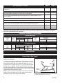
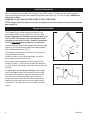
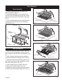
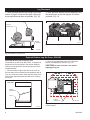
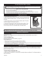
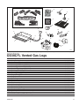
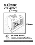
Installation and Operation
Instructions for
Vented Gas Log Sets
Model OD30CFLN/P
GAS-FIRED
CERTIFIED
DECORATIVE GAS APPLIANCE FOR INSTALLATION IN SOLID FUEL BURNING FIREPLACES
WARNING
IF THE INFORMATION IN THIS MANUAL IS NOT FOLLOWED EXACTLY, A FIRE OR EXPLOSION MAY RESULT,
CAUSING PROPERTY DAMAGE, INJURY, OR LOSS OF LIFE.
FOR YOUR SAFETY:
Do not store gasoline or other flammable
vapors or liquids near this or any other appliance.
WHAT TO DO IF YOU SMELL GAS:
• SHUT OFF ALL GAS TO THE APPLIANCE.
• DO NOT TRY TO LIGHT ANY APPLIANCE; EX-
ATTENTION
INSTALLATION AND SERVICE MUST BE PERFORMED BY A QUALIFIED AGENCY, INDIVIDUAL,
FIRM, CORPORATION, OR COMPANY, EXPERIENCED IN THE INSTALLATION, REPAIR, AND
SERVICING OF THIS TYPE OF GAS APPLIANCE.
DO NOT MODIFY, ALTER OR TAMPER WITH ANY
PART OF THIS HEATER, CONTROL, OR LOGS.
TINGUISH ANY OPEN FLAME
• IMMEDIATELY PHONE YOUR GAS SUPPLIER
•
FROM A NEIGHBOR’S PHONE. FOLLOW THE
SUPPLIER’S INSTRUCTIONS.
IF YOU CANNOT REACH THE GAS SUPPLIER,
PHONE THE FIRE DEPARTMENT.
Certified as:
CSA 7.94 U.S. manually lighted decorative gas appliance
for installation in solid fuel burning fireplaces and the applicable requirements of UL127 factory-suit fireplaces.
INSTALLER PLEASE NOTE:
DO NOT BEGIN INSTALLATION OF THIS GAS
LOGSET UNTIL ALL INSTRUCTIONS HAVE
BEEN READ AND UNDERSTOOD.
OWNER PLEASE NOTE:
READ THESE INSTRUCTIONS AND FOLLOW THE
WARNINGS.
CAN 1-2.21-M85 Gas Fired Appliances for Outdoor
Installation
CFM Specialty Home Products
410 Admiral Blvd. • Mississauga, Ontario, Canada L5T 2N6 • 905-670-7777
www.majesticproducts.com • www.vermontcastings.com
SAVE THIS MANUAL FOR FUTURE REFERENCE
20004180 10/05 Rev. 2
WARNING
Improper installation, adjustment, alteration, service or maintenance can cause injury or property damage. Read these directions thoroughly before installation. For assistance or additional information,
consult your gas log dealer, qualified installer, service agency or
gas supplier.
WARNING
If not installed, operated, and maintained in accordance with the manufacturer’s instructions, this product could expose you to substances in fuel or fuel combustion which are known to the State of California
to cause cancer, birth defects, or other reproductive harm.
WARNING
Young children are not allowed to operate this unit and must be supervised when they are in the same
area as the appliance.
INSTALLATION PRECAUTIONS
Fireplace damper MUST be locked fully open when operating the gas log set.
If the fireplace has glass doors, operate gas log set only with doors fully opened. The fireplace
screen must be in place when the appliance is operating and, unless other provisions for combustion
air are provided, the screen shall have an opening(s) for introduction of combustion air.
The log set and its individual shut-off valve MUST be isolated from the gas supply piping system by
closing its individual shut-off valve during any pressure testing of gas supply at test pressures equal to
or less than 1/2 psig.
The log set and its individual shut-off valve MUST be disconnected from the gas supply piping system
during any pressure testing of that system at test pressures in excess of 1/2 psig.
Keep the gas log set clear and free from combustible materials, gasoline and other flammable vapors
and liquids.
If the log set is to be installed in a fireplace other than the Vermont Castings ODSHR42 fireplace, the
minimal firebox dimensions and stainless steel grate must be used. Refer to Page 12 for Optional Accessories.
Proposition 65 Warning: Fuels used in gas, woodburning or oil fired appliances, and the products of
combustion of such fuels, contain chemicals known
to the State of California to cause cancer, birth defects and other reproductive harm.
California Health & Safety Code Sec. 25249.6
2
20004180
General Information
In order to assure a safe and effective installation, only a qualified service person who is
familiar with the building codes and installation
techniques appropriate to your area may install
and service this appliance.
The Logsets have been designed and tested to operate safely when installed according to the installation
instructions contained in this manual. Read all instructions before starting the installation.
• For outdoor use only.
• The logset should be inspected before use and at
least annually thereafter. More frequent cleaning may
be necessary because of excessive lint from carpeting
or bedding material.
• In the United States, the installation and operation
must conform to local codes or, in the absence of local
codes, with the National Fuel Gas Code, ANSI Z223.1,
latest edition, CSA B149.1 Installation Code, and with
the National Electrical Code, ANSI/NFPA70 (latest edition).
• The gas logset and its individual shutoff valve must be
disconnected from the gas supply piping system during
any pressure testing of that system at test pressures in
excess of 1/2 p.s.i.g. (3.5 kPa) The gas logset must be
isolated from the gas supply piping system by closing
its individual manual shutoff valve during any pressure
testing of the gas supply piping system at test pressures equal to or less than 1/2 p.s.i.g. (3.5 kPa)
• Do not, under any circumstances, burn solid fuel
(wood, paper, coal) in the fireplace where you have
installed your logset. Do not use it for cooking. Put
nothing on top of the logs.
• The logset must be compatible with its fuel. Natural
gas requires different hardware than propane. Never
attempt to use natural gas with a propane logset or vice
versa.
• For a propane burning logset, the supply tank must
include a high to low gas pressure regulator. The tank
must be outdoors. Do not, under any circumstances,
locate supply tanks inside any structure.
• The fireplace must include a screen made of chain
mesh or a similar material. You must keep the screen
closed at all times during the operation of the logset; it
will protect you in the event of an explosion.
20004180
• WARNING: If the fireplace contains glass doors,
they must remain open at all times during the operation of the logset, allowing combustion air to circulate.
• In order to avoid any possible gas leaks, apply pipe
joint compound to all non-flared threaded connections
involved in this installation. For propane, the joint
compound must be resistant to the corrosive action of
propane.
• To check for leaks, always use a soapy water solution or a sniffer. Never test by using an open flame.
• The area around the gas logset must be free of all
combustible materials, especially gasoline or other
highly flammable, vapor producing liquids.
• Due to high temperatures, locate this logset away
from both high traffic areas and furniture and draperies.
• Children and adults alike should be aware of the
high surface temperatures; to avoid the risk of burns
or ignition of clothing they should stay away.
• Do not touch any part of the logset other than the
controls while it is operating or immediately after you
turn it off.
• Supervise young children and pets carefully when
they are in the area where the logset is operating.
• Do not place clothing or other flammable material on
or near the logset.
•Make sure that any safety screen or guard, removed
during servicing, has been replaced before you use
the logset.
• It is imperative that you keep clear all burner areas,
control compartments and passageways for circulating air.
• Do not move the logset in any way that might dislodge the logs from their fixed positions. If you bump
the logset check to see if you have dislodged anything.
• Provide adequate clearances around air openings
into the combustion chamber and adequate accessibility clearance for servicing and proper operation.
NEVER obstruct the front opening of the fireplace.
3
Pre-Installation Checklist
Yes
No
Is the gas type you are using the same as the gas type listed on the rating plate for this
appliance?
Does the firebox meet the minimum size dimensions below?
Is the gas supply inlet pressure correct? Refer to Table below.
Is your fireplace plumbed with gas on the right side (facing) of the fireplace? If not,
refer to page 5.
Is the gas supply line sized properly (Minimum 1/2” Iron pipe)?
Do you have a solid fuel (wood burning) fireplace with a vented flue?
Do you have a manual gas supply valve installed at your fireplace? If not, a licensed
plumber, gas company technician or other qualified installer must install one:
Have you checked local building codes? (Check with your local building department)
Does your fireplace have a wire mesh screen in place?
CAUTION: If you answered “NO” to any item, or have any questions regarding your installation, please contact your dealer/distributor for assistance.
Minimum Clearances & Specifications
Natural Gas Units
Gas Log
Set
Size
30”
Input
Btu/hr
90,000
Minimum Firebox Dimensions
Width
Back
Front
Depth Height
27”
36”
18”
18”
Minimum
Flue
Size
79 sq.in.
Gas Supply
Pressure
Minimum
Maximum
3.5” w.c.
7.0” w.c.
Propane Gas Units
Gas Log
Set
Size
30”
Input
Btu/hr
60,000
Minimum Firebox Dimensions
Width
Back
Front
Depth Height
27”
36”
18”
18”
Minimum
Flue
Size
79 sq.in.
Gas Supply
Pressure
Minimum
Maximum
11.0” w.c.
14.0” w.c.
Tools Required
8” adjustable crescent wrench; Pipe thread sealant compound or teflon tape; 12” pipe wrench or channel lock pliers.
Connection to Gas Supply
NOTE: For Natural and Propane gas, you must have a manual
shutoff at the fireplace.
1
1. Place the burner pan in the fireplace. Two options are given to
2
place the burner under the grate in the fireplace; Option 1: Pull the
grate so that the back side of the hearth brick pulls up (1, Fig. 1)
enough for you to tilt the grate up (2, Fig. 1) to slide the pan underneath (3, Fig. 1). Option 2: Remove the two sheet metal screws
from the retaining brackets on the bottom feet of the rear grate legs,
3
then remove the grate. The burner should be located several inches
from the back wall, centered left to right.
NOTE: If logset is installed in a fireplace other than the ODSHR42
FP1150
fireplace, remove the grate that is in the fireplace and install the
Fig. 1 Pull back of grate and hearth brick up, tilt front
grate listed on Page 12 of Optional Accessories.
of grate up and slide burner pan under.
4
FP1150
OD30
lift grate
9/10/01 djt
20004180
NOTE: This is for burner connection purposes only. Exact burner placement will be covered on Page 7, after
all connections have been made.
3. Attach the Gas Supply Fitting onto your fireplace’s
gas supply pipe, as shown in Figure 2.
4. Attach one end of the Flexible Gas Connector to
the brass Burner Inlet Fitting which has been factory
installed into the burner.
5. Attach the other end of the Gas Connector to the
flared side of the Gas Supply Fitting.
Remember to use pipe thread sealant or teflon tape
only on the straight pipe threads. Do not use on
any flared ends.
CFM149
Fig. 2 Natural gas connection.
Gas Plumbed On Left Hand Side Of
Fireplace
CFM149
R-CFL Gas Supply Connection
NOTE: Your gas log set is assembled at the factory to be installed in a fireplace plumbed with the gas on
2/14/01 sta
the right side (facing). If your fireplace is plumbed with the gas on the left side remove fittings on right and
left side of straight burner tube and switch sides, at the same time put front burner tube on right side with
the elbow fitting (Refer to Figs. 3,4).
You may also run a flexible connector (or as per local codes) along the back wall of the fireplace to bring
your gas line to the right hand side. You can then place the set in front of the flexible connector (Fig. 4).
Rigid Pipe. Flexible Hose or Copper Tubing
Approved for Outdoor Use
Regulator
Supplied w/LP Unit
To Gas Supply
Gas Inlet 3/8”
Pipe Coupling
3/8” Brass Elbow
NPT to Flare
Parts Not
Supplied
Flex Hose
FP1143
Fig. 3 LP gas connection.
FP1143
OD30CFL
LP hook up
8/10/01 djt
CFM159
Fig. 4 Alternate left side gas
20004180
CFM150
CFM159
connection.
R-CFL Gas Supply Connection
2/14/01 sta
5
CFM150
Leak Test Procedures
After connecting the gas supply, test for leaks. Use a 50/50 solution of liquid soap and water to test for
leaks at gas fitting and joints. Apply water/soap solution with brush only - do not over apply. NEVER test
with an open flame.
WARNING: DO NOT USE AN OPEN FLAME TO TEST FOR LEAKS!
NOTE: Always perform a leak test any time the appliance has been moved or disconnected from the
gas supply line.
Damper Stop Installation
The Damper Stop provided keeps your damper from
accidentally closing during operation of your set. This
Damper Stop must be installed onto your Damper at all
times. NOTE: The damper clamp is designed to hold
the damper plate open 3 inches. However, the damper
must be fully open when the log set is in operation.
Install the Damper Stop onto the edge of the damper plate.
Attach by securing the bolt provided to the damper plate
with an adjustable wrench. (Fig. 5)
If the Damper Stop does not fit, drill a 1/4” hole into the
damper plate and install an
anchor bolt with nut, at a 90 degree angle, so that the
damper plate will remain fully open.
The proper finished installation of the Damper Stop is
shown in Figure 6. If the bolt fails to block the damper in
an open position, the damper should be removed from the
chimney.
To check your vent for proper drafting: Light a tightly
rolled newspaper on one end and place it at the inside
front edge of the fireplace. Observe the smoke and be
sure the vent is properly drawing it up the chimney. If
the smoke is drawn back into the room, extinguish the
flame and remove any obstruction until proper venting
is achieved. If that fails, check with a qualified chimney
sweep.
6
Damper
Plate
Damper
Stop
DP104
Fig. 5 Attach damper clamp.
DP104
Damper clamp
Harris
Chimney
Clamp
Damper
DP103
Fig. 6 Damper
DP103
clamp
installation.
Damper clamp
Harris
20004180
Grate Placement
Grate Assembly
1. Place the grate steps onto the back of the
grate as shown in Figure 7.
2. Place grate assembly over top of burner so
that the front two middle legs of grate are resting
against the front portion of the main burner area.
(Fig. 7)
3. If the retaining bracket on the rear bottom feet
of the grate were removed for pan installation,
replace them now.
Lava Rock
Pan
Assembly
FP1145
Fig. 8 Lava rock placement.
Grate Steps
FP1145
OD30 lava rock
8/13/01 djt
Grate
(ODSHR42,
20002230)
Main
Burner
Glowing Embers
FP1146
Fig. 9 Ember placement.
Front
Ember Pan
FP1144
Fig. 7 Grate assembly.
FP1146
OD30 embers
8/13/01 djt
Add Pan Material
1. With burner pan and grate in place, open the
bag of lava rock and spread it evenly across the
FP1144
pan assembly to the top of the pan assembly. (Fig.
Grate Assy
8)
8/13/01 djt
2. Open one bag of glowing embers and place
evenly across burner covering lava rock. (Fig. 9)
3. Slide the mesh screen under the grate, but on
top of glowing embers so the mesh piece covers
the burner pan material. (Fig. 10)
Embers
Ember Screen
FP1147
Fig. 10 Screen and ember placement.
FP1147
OD30
Screen & embers
8/13/01 djt
4. Open remaining bag of embers and place
evenly on top of mesh screen. (Fig. 10)
5. Spread lava rock onto fireplace hearth around
the burner pan for decorative purposes. (Fig. 11)
Lava Rock
FP1148
Fig. 11 Place lava rock on fireplace hearth for decoration.
20004180
7
Log Placement
1. Place the larger bottom logs (longer log in back,
shorter (2) logs in front) onto the grate, leaving as
much space between them as possible. (Fig. 12)
2. Next, place the smaller top logs diagonally onto
the bottom logs, so that the logs are in notches
provided. (Fig. 13)
Long Log
Front (2)
Shorter Logs
Grate
Retainer
LG174
Fig. 13 OD30CFL log set.
LG174
OD30CFL
log set
8/14/01
FP1149
Fig. 12 OD30CFL log placement.
Optional Outdoor Log Set Cover, ODLSSC
CAUTION: Be sure
pilot (if used) is OFF.
FP1149
The Outdoor LogOD30
Set Cover, #UC1SSO, is designed to
loglogs
placement
be placed over the
while in the outdoor fireplace.
8/14/01 from direct exposure to the
This will provide protection
outside elements.
2. Place the second half of the cover in the same
manner, overlapping the first half. (Fig. 15)
CAUTION! Be sure to remove cover before
lighting gas log set.
1. Place the bottom edge of one side of the cover on
the front edge of the hearth brick just behind the ash lip
(Fig. 14), inside the screens. Allow the back edge of the
cover to rest against the back and side brick, covering
the log set.
Side View
Outdoor
Logset Cover
Ash Lip
KT259
KT260
Fig. 14 ODLSSC installation side view.
8
KT260
ODLSSC
side view
Outdoor
Logset Cover
Ash Lip
Fig. 15 Place log set cover over logs behind screens in
outdoor fireplace.
KT259
ODLSSC
8/21/01 djt
20004180
For Your Safety Read Before Lighting
WARNING: If you do not follow these directions exactly, a fire or explosion may result causing property damage, personal injury, or loss of life.
What To Do If You Smell Gas
•
•
•
•
Do not try to light any appliance.
Do not touch any electrical switch, do not use any phone in the immediate area.
Immediately call your gas supplier from a neighbor’s phone. Follow the gas supplier’s instructions.
If you cannot reach your gas supplier, call the fire department.
Lighting Instructions
1. Turn the gas shut-off valve to OFF.
2. Wait five (5) minutes to clear out any gas. If you then smell gas STOP!
Follow the safety information above. If you don’t smell gas, go on to the
next step.
3. Light a match and lay it on top of the pan material, about 2” from the
end of the supply side of the pan (Fig. 16).
4. Slowly turn the gas shut-off valve ON until the burner ignites. If the
burner doesn’t ignite within ten (10) seconds with the match burning,
turn the shut-off valve OFF and repeat steps 1 through 4 again.
LG175
Match
Fig. 16 Lighting the log set.
WARNING: Flame may flare up when ignited. Keep hands and face away from firebox.
Operation and Maintenance
LG175
OD30CFL
log set light
8/14/01
To Adjust the Flame:
Adjust the flame to the desired level by rotating the gas valve counterclockwise
to open or
clockwise
to close.
To Turn the Appliance Off:
to off.
Rotate the gas shut-off valve clockwise
Proper Maintenance:
• Keep the area around the log set clean and clear of debris.
• Occasionally, you may use a soft bristle brush to clean logs.
• Once every year, a qualified agency or certified chimney sweep should examine and clean the venting
system of the fireplace in which the log set is installed.
Appliance Break-in
During the 2-3 hour appliance break-in period, you may detect an odor from the appliance as the various
water-based paints used in the manufacture of this log set cure. This is a normal and temporary situation
that is not a cause for alarm.
To ensure proper curing of the logs:
1. Ignite a 2” flame and maintain it for 1/2 hour.
2. Burn the logs in consecutive 1/2 hour periods, raising the flame an additional 2” to full flame height for a
total of three hours.
20004180
9
Troubleshooting
Log Set Is Smoking/Sooting Excessively
It is natural and unavoidable for vented gas log sets to produce moderate levels of carbon (soot) where
flame contacts the logs. The logs can be cleaned using a soft-bristle brush. However, if soot is produced where there is no flame impingement, one of the following may be the cause:
Fireplace venting system not drafting properly: Make sure the damper is wide open at all times.
Preheat the flue in very cold weather by burning the log set at a very low level, then slowly increasing the flame height over a matter of hours. Have the fireplace and the venting system professionally
cleaned.
Excessive flame impingement or blockage: Make sure there is proper spacing between the logs so
they are not smothering the flame. Rearrange the logs so they are touched less by the flames.
Excessive gas supply/pressure: Make sure the gas pressure coming into the fireplace does not exceed the maximum pressure allowed with this gas set (refer to tables on page 4). If you are using the
gas logs with a safety pilot kit, make sure you installed the correct orifice into the set.
Burner Is Excessively Noisy
Please note: The movement and combustion of gas will create low, unavoidable levels of noise.
Excessive gas pressure: Make sure the gas pressure coming into the fireplace does not exceed the
maximum pressure allowed with this gas set (refer to tables on page 4). If you are using the gas logs
with a safety pilot kit, make sure you installed the correct orifice into the set.
Passage of air/gas across irregular surfaces: There may be burrs, paint, or other blockages on the
burner bar ports. Check these ports and remove any blockage.
Gas Connector: Relieve any tight bends or kinks in the Flexible Gas Connector. Switch to a smooth
aluminum gas connector, which can be purchased at any hardware or home improvement store.
Burner Flame Is Too High (8-12” Above Top Logs) Or Too Low
(Below Top Logs)
Incorrect gas supply, pressure, or burner orifice used: Make sure the gas pressure coming into
the fireplace falls between the minimum and maximum pressures allowed with this gas set (refer to
tables on page 4). If you are using the gas logs with a safety pilot kit, make sure you installed the
correct orifice into the set.
Blocked ports (low flame only): Free the main burner orifice and burner bar ports of any burrs,
paint, or other blockage.
10
20004180
4
2
1
5
c
b
d
a
e
3
f
g
13
h
12
11
16
6
17
14
9
10
7
15
18
8
19
4108
CFM Specialty Home Products reserves the right to make changes in design, materials, specifications, prices and discontinue colors and products
at any time, without notice.
OD30CFL Vented Gas Logs
Ref.
1.
1a.
1b.
1c.
1d.
1e.
1f.
1g.
1h.
2.
3.
4.
5.
6.
7.
8.
9.
10.
11.
12.
13.
14.
Description
Complete Log Set
Outside Left Cross Log (NNS2)
Left Cross Log (NNS4)
Center Left Cross Log (NEO-2)
Center Right Cross Log (NNO-3)
Outside Right Cross Log (NNS-3)
Back Log (NNS30B)
Front Left Log (KO-30L)
Front Right Log (KO-24L)
Bag of Glowing Embers
Bag of Lava Rock
Grate Step
Damper Stop
Burner Tube - 3/8”
Pan Assembly
Orifice - Natural Gas
Burner Inlet Fitting
Flexible Gas Connector
Gas Supply Fitting - Elbow
3/8” Brass Female NPT to Flare - Propane
Ember Screen
3/8” Brass Elbow, NPT to Flare - Propane
20004180
4108
OD3CFL
parts
8/14/01
OD30CFL
20003917
4312778
4312780
4312847
4312848
4312779
4312814
4312857
4312844
4310001
3310041
20004202
20002575
20003828
20004179
20000961
20000958
3304176
3304145
3304146
20004567
3304006
11
OD30CFL Vented Gas Logs
Ref.
15.
16.
17.
18.
19.
(continued)
Description
Regulator - Propane
Orifice - Propane
Orifice Holder - Propane
Air Mixer Shutter
Air Shutter Screen
OD30CFL
3304191
20001280
20000012
20000013
20004686
Optional Accessories
Item
Grate (Stainless Steel)
12
Description
For use in fireplaces other than the ODSHR42
Part Number
20002230
20004180
20004180
13
14
20004180
LIMITED 2/20 YEAR WARRANTY
For VERMONT CASTINGS Decorative Gas Appliances
CFM Specialty Home Products extends the warranties
specified in paragraphs A and B below with respect to its
Vermont Castings Decorative Gas Appliances (the “Gas Appliance”), including CFM Specialty Home Products supplied
accessories and components referred to in those paragraphs, subject to the following conditions and limitations:
(1) These warranties are extended only to the Gas Appliance installed in the continental United States, including
Alaska, and Canada; only if and so long as the accordance
with the installation and operating instructions furnished
therewith; and only if and so long as Gas Appliance is not
removed from its original installation.
(2). These warranties are limited to only the component
parts manufactured and supplied by CFM Specialty Home
Products. The use of components manufactured by others
with the Gas Appliance (except for a listed Type B venting
system as defined in the installation instructions) could create serious safety hazard, may result in the denial of certification by recognized national safety agencies, and could be
in violation of local building codes.
(3). The Gas Appliance must be operated at all times in
accordance with the operating instruction furnished therewith. The Gas Appliance is designed to burn either natural or
propane gas only. Burning conventional fireplace fuels such
as wood, coal, or any other solid fuel will cause damage to
the Gas Appliance, will produce excessive temperatures and
will result in a fire hazard.
(4). These warranties are limited to repair, replacement or
furnishing a replacement for sale, as specified in Paragraphs
A and B, for a part found to CFM Specialty Home Products
satisfaction, after examination, to be defective in materials or
workmanship under normal conditions, use and service.
(5). All obligations with respect to these warranties may
be fully discharged by CFM Specialty Home Products refunding the wholesale price of a defective part.
(6) Except as otherwise expressly specified in Paragraphs A and B. NONE OF THESE WARRANTIES COVER,
AND CFM SPECIALTY HOME PRODUCTS SHALL NOT
BE RESPONSIBLE FOR, ANY CONSTRUCTION, INSTALLATION, LABOR, TRANSPORTATION OR OTHER COSTS
OR EXPENSES ARISING FROM A DEFECTIVE PART,
ITS REPAIR OR REPLACEMENT OR OTHERWISE, NOR
SHALL CFM SPECIALTY HOME PRODUCTS IN ANY
EVENT BE RESPONSIBLE FOR ANY INDIRECT, INCIDENTAL OR CONSEQUENTIAL DAMAGES. EXCEPT TO THE
EXTENT PROVIDED BY LAW, THERE ARE NO IMPLIED
WARRANTIES WITH RESPECT TO THE GAS APPLIANCE,
ITS COMPONENTS AND ACCESSORIES (INCLUDING
IMPLIED WARRANTIES OF MERCHANTABILITY OR FIT-
20004180
NESS FOR A PARTICULAR PURPOSE), ALL OF WHICH
ARE HEREBY EXPRESSLY INCLUDED. IN NO EVENT
SHALL ANY IMPLIED WARRANTY PRESCRIBED BY LAW
(NOTWITHSTANDING THE FOREGOING EXPRESS EXCLUSION) REMAIN IN EFFECT AFTER EXPIRATIONS OF
THE WARRANTIES SET FORTH IN PARAGRAPHS A AND
B.
A. Gas Appliances, electrical and manual components, glass panels, all sealants or adhesives and
optional accessories (exclusive of CFM Specialty Home
Products supplied decorative logs which are covered by a
separate warranty under paragraph B below):
Within two years from the date of manufacture of the
gas appliance, CFM Specialty Home Products will repair, or
replace (at our option) a defective part without charge.
B. Cement or ceramic fiber log components:
Within two years from the date of manufacture of the gas
appliance, CFM Specialty Home Products will replace a
defective part without charge. Within years three through
twenty from the date of manufacture of the gas appliance,
CFM Specialty Home Products will provide a replacement
for a defective part to the homeowner, but assumes no liability for incurred labor cost.
The foregoing warranties gives you specific legal rights
and you may also have other rights which vary from state to
state. Some states do not allow limitations on how long an
implied warranty may last, so the limitation specified above
on the duration of any implied warranty prescribed by law
may not apply to you. Similarly, some states do not permit
the exclusion or limitation of incidental or consequential
damages, so the above exclusion of such damages may not
apply to you.
In order to obtain performance of any of the above warranty obligations, write to CFM Specialty Home Products at
this address:
CFM Specialty Home Products
410 Admiral Blvd
Mississauga, Ontario Canada L5T 2N6
Attention: Manager of Warranty Services
Since local building requirements may vary greatly
throughout the country, users of CFM Specialty Home Products products should determine in advance whether there
are any building code restrictions on the use of a specified
product.
CFM SPECIALTY HOME PRODUCTS MAKES NO REPRESENTATION OR WARRANTY REGARDING, AND SHALL
NOT BE RESPONSIBLE FOR, ANY BUILDING CODE
COMPLIANCE. The foregoing warranties give you specific legal
rights and you may also have other rights which vary from state to state.
15
CFM Specialty Home Products
410 Admiral Blvd. • Mississauga, Ontario, Canada L5T 2N6 • 905-670-7777
www.majesticproducts.com • www.vermontcastings.com