1
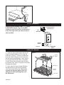
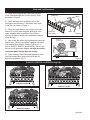
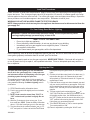
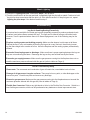
Installation and Operation Instructions for Vented Gas
Log Set - DragonFire Hearth Kits
Models A18CFLRN/P, A24CFLRN/P, A30CFLRN/P
DECORATIVE GAS APPLIANCE FOR INSTALLATION IN SOLID FUEL BURNING FIREPLACES
Design Certified to ANSI Z21.60 and CGA 2.26 Standards
WARNING
IF THE INFORMATION IN THIS MANUAL IS NOT FOLLOWED EXACTLY, A FIRE OR EXPLOSION MAY RESULT,
CAUSING PROPERTY DAMAGE, INJURY, OR LOSS OF LIFE.
FOR YOUR SAFETY:
DO NOT STORE GASOLINE OR OTHER FLAMMABLE VAPORS OR LIQUIDS NEAR THIS OR ANY
OTHER APPLIANCE.
WHAT TO DO IF YOU SMELL GAS:
• SHUT OFF ALL GAS TO THE APPLIANCE.
• OPEN WINDOWS; DO NOT TOUCH ANY ELECTRICAL SWITCHES. DO NOT USE ANY PHONE IN
•
•
•
YOUR BUILDING.
DO NOT TRY TO LIGHT ANY APPLIANCE; EXTINGUISH ANY OPEN FLAME
IMMEDIATELY PHONE YOUR GAS SUPPLIER FROM A NEIGHBOR’S PHONE. FOLLOW THE SUPPLIER’S INSTRUCTIONS.
IF YOU CANNOT REACH THE GAS SUPPLIER, PHONE THE FIRE DEPARTMENT.
ATTENTION
INSTALLATION AND SERVICE MUST BE PERFORMED BY A QUALIFIED AGENCY, INDIVIDUAL, FIRM, CORPORATION, OR COMPANY,
EXPERIENCED IN THE INSTALLATION, REPAIR,
AND SERVICING OF THIS TYPE OF GAS APPLIANCE. DO NOT MODIFY, ALTER OR TAMPER
WITH ANY PART OF THIS HEATER, CONTROL,
OR LOGS. INSTALLER, CHECK LOCAL CODES
BEFORE INSTALLING THIS LOG SET. IN SOME
AREAS OF THE COUNTRY GAS LOG SETS ARE
RESTRICTED.
INSTALLER PLEASE NOTE:
DO NOT BEGIN INSTALLATION OF THIS GAS
LOG SET UNTIL ALL INSTRUCTIONS HAVE BEEN
READ AND UNDERSTOOD. AFTER INSTALLATION, LEAVE THESE INSTRUCTIONS WITH THE
OWNER.
OWNER PLEASE NOTE:
READ THESE INSTRUCTIONS AND FOLLOW
THE WARNINGS. PLEASE RECORD YOUR
GAS LOG’S MODEL NUMBER FOR FUTURE
REFERENCE:
DE S I GN
CFM Specialty Home Products
CE
RTIFI E D
410 Admiral Blvd. • Mississauga, Ontario, Canada L5T 2N6 • 905-670-7777
www.majesticproducts.com • www.vermontcastings.com
C E RT I F I E D
SAVE THIS MANUAL FOR FUTURE REFERENCE
20003903 4/05 Rev. 9
WARNING
Improper installation, adjustment, alteration, service or maintenance can cause injury or property
damage. Read these directions thoroughly before installation. For assistance or additional information, consult your gas log dealer, qualified installer, service agency or
gas supplier.
WARNING
WARNING
Do not use this appliance or any part that has
been under water. Immediately call a qualified
service technician to inspect the appliance and
to replace any part of the control system and
any gas control which has been under water.
If not installed, operated, and maintained in
accordance with the manufacturer’s instructions, this product could expose you to substances in fuel or fuel combustion which are
known to the state of California to cause cancer, birth defects, or other reproductive harm.
WARNING
A properly sized, unobstructed chimney will normally vent all fumes and products of combustion. Any
odor or smoke detected in the room is an indication that the flue is not properly removing the combustion products. Turn off the gas supply valve immediately! The cause of the venting problem must be
discovered and corrected before using this gas log set. Disregarding this warning can cause illness as
well as soot damage to your fireplace, room, and furnishings.
WARNING
Young children are not allowed to operate this unit and must be supervised when they are in the same
room as the appliance. Due to high temperatures, the appliance should be located out of traffic and
away from furniture and draperies. In addition, clothing or other flammable material should not be
placed on or near the appliance.
Technical Information
The operation of a gas log set, and the provision for combustion and ventilation air must
conform with the National Fuel Gas Code, ANSI Z223.1/NFPA 54 and applicable codes.
Gas Pressure Testing: This gas log set and its individual shut-off valve MUST be
disconnected from the gas supply piping system during any pressure testing of that system at test
pressures in excess of 1/2 psig (3.5 kPA). The gas log set must be isolated from the gas supply piping
system by closing its individual manual shut-off valve during any pressure testing of the gas supply
piping system at test pressures equal to or less than 1/2 psig (3.5 kPa)
Component Parts: Only factory authorized components listed in these instructions may be used in
accordance with the manufacturer’s instructions and all codes and requirements of the authority having jurisdiction. Any modifications to this kit, or use of unauthorized components or accessory items
will void the manufacturer’s warranty, and may result in a hazardous condition.
2
20003903
Before You Begin -- ATTENTION!
A. The appliance should be inspected before use and at least annually by a professional
service person. More frequent cleaning may be required due to excessive lint from
carpeting, bedding material, etc. It is imperative that control compartments, burners and
circulating air passageways of the appliance be kept clean.
B. Your fireplace must include a chain mesh or similar screen. The screen must remain
fully closed while operating your log set. Any safety screen or guard removed for
servicing this appliance must be replaced prior to operation.
C. If your fireplace includes glass doors, they must remain fully open to allow for combustion
air during operation, and to prevent overheating of the gas valve.
D. Your log set must be installed in a solid fuel burning fireplace constructed of
noncombustible material with a working flue.
E. Solid fuels shall not be burned in the fireplace where your gas log set is installed.
F.
If this log set is to be used with propane gas, your propane supply tank MUST include a
high to low gas pressure regulator, and must be located outside. DO NOT place supply
tanks inside any structure .
G. Never use sand or other dense pan material with propane gas: use vermiculite only.
H. Be sure to apply pipe joint compound to all non-flared, threaded connections involved in this
installation to avoid possible gas leaks. Compounds used in liquid propane
applications must be resistant to the action of that gas.
I.
Always test for leaks using a soapy solution. NEVER USE OPEN FLAME.
J. The manufacture and shipping of your log set involves compounds which may cause
detectable yet harmless odors during initial operation. Provide extra ventilation to the
room for the initial 2-3 hour break-in period.
K. This gas log set may be installed in the approved fireplace in an aftermarket* manufactured
(mobile) home where not prohibited by state or local codes.
*Aftermarket: Completion of sale, not for purpose of resale, from the manufacturer.
L. The fireplace damper MUST be fully open when operating this log set.
Fireplace Specifications
Before installation, the chimney flue, venting system, and firebox must be cleaned of all soot,
creosote, ashes and loose paint, by a qualified chimney cleaner.
Your Fireplace Must Include:
• A working flue and venting system with the minimum openings indicated on Page .
• A gas supply shut off valve. If your fireplace does not have such a valve, one must be installed.
20003903
3
YES
Pre-Installation Check List
NO
Is the gas supply inlet pressure correct?
NG: Min. 5.0” w.c./ Max. 10.5” w.c.
LP: Min. 11.0” w.c.;Max. 14.0” w.c.
Does the firebox meet the minimum size dimensions below?
Is your fireplace plumbed with gas on the right side (facing) of the fireplace? If not, see
page 10.
Is the gas supply line sized properly (Minimum 1/2” Iron Pipe)?
Do you have a solid fuel (wood burning) fireplace with a vented flue?
Do you have a manual gas supply valve installed at your fireplace? If not, a licensed
plumber, gas company technician or other qualified installer must install one.
Have you checked local building codes? (Check with your local Building Dept.)
Does you fireplace have a wire mesh screen in place?
CAUTION: If you answered “NO” to any item, or have any questions regarding your installation,
please contact your dealer/distributor for assistance.
Natural Gas Units -- Minimum Clearances & Specifications
Set
Size
18”
24”
30”
Input
Btu/hr
54,000
75,000
75,000
Min. Firebox Dimensions
Width
Back Front Depth Height
19” 27”
15”
18”
23” 33”
15”
18”
30” 39”
18”
18”
Minimum
Flue
Size
51 sq.in.
51 sq.in.
79 sq.in.
Gas Fuel Line
Pressure
Minimum Maximum
5” w.c.
10.5” w.c.
7” w.c.
10.5” w.c.
7” w.c.
10.5” w.c.
Manifold
Pressure
3.5” w.c.
3.5” w.c.
3.5” w.c.
Propane Gas Units -- Minimum Clearances & Specifications
Set
Size
18”
24”
30”
4
Input
Btu/hr
40,000
45,000
60,000
Min. Firebox Dimensions
Width
Back Front Depth Height
19” 27”
15”
18”
23” 33”
15”
18”
30” 39”
18”
18”
Minimum
Flue
Size
51 sq.in.
51 sq.in.
79 sq.in.
Gas Fuel Line
Pressure
Minimum Maximum
11” w.c.
14” w.c.
11” w.c.
14” w.c.
11” w.c.
14” w.c.
Manifold
Pressure
11” w.c.
11” w.c.
11” w.c.
20003903
Tools Required
8” adjustable crescent wrench; Pipe thread sealant compound or teflon tape; 12” pipe wrench or channel
lock pliers.
Gas Plumbed on Left Hand Side of Fireplace
NOTE: Your gas log set is assembled at the factory to be installed in a fireplace plumbed with the gas on
the right side (facing). If your fireplace is plumbed with the gas on the left side remove fittings on right and
left side of straight burner tube and switch sides, at the same time put front burner tube on right side with
the elbow fitting. (Fig. 5b)
You may also run a flexible connector (or as per local codes) along the back wall of the fireplace to bring
your gas line to the right hand side. You can then place the set in front of the flexible connector. (Fig. 5a)
Damper Stop Installation:
For Use with BR, BC, SR, SC, TF and TL Series CFM Specialty Home Products Fireplaces
This Damper Stop is designed to work on all CFM
Specialty Home Products BR, BC, SR, SC, TF and
TL series fireplaces. For all other fireplaces, refer
to Page 6.
Damper
Plate
When installing a decorative gas appliance in a
fireplace, some local codes require this Damper
Stop to be used so the Damper will not close completely. To install the Damper Stop:
The Damper Locking Bracket is already installed
on all BR, BC, SR, SC, TF and TL fireplaces. Locate the Damper Locking Bracket on the left side
of the fireplace’s Combustion Dome.
(Fig. 1)
Damper Locking Bracket
Figure 1
With the Damper open, align the two slots on
either side of the cut-out on the Damper Stop with
the two small holes on the angled portion of the
Damper Locking Bracket. Attach the Damper
Stop with the Screws provided, as shown in
Figure 2.
NOTE: Some of the early fireplace units may not
have the holes in the end of the Damper Locking Bracket. If this is the case, use the Damper
Stop as a template to drill two (2) 1/8” holes in the
Damper Locking Bracket to mount the Damper
Stop.
LS854
Damper Locking Bracket
Damper Stop
Figure 2
LS854
Locate damper
lock bracket
11/99
Damper
Stop Screw
LS855
5
20003903
LS855
Attach damper stop
Damper Stop Installation:
For Use with All Other Fireplaces
The Damper Stop provided keeps your damper from accidentally closing during operation of your set. This Damper Stop
must be installed onto your Damper at all times. NOTE: The
damper clamp is designed to hold the damper plate open 3
inches. However, the damper must be fully open when the
log set is in operation.
Figure 3
Install the Damper Stop onto the edge of the damper plate. Attach by securing the bolt provided to the damper plate with an
adjustable wrench. (Fig. 3)
Damper
Plate
If the Damper Stop does not fit, drill a 1/4” hole into the damper
plate and install an
anchor bolt with nut, at a 90 degree angle, so that the damper
plate will remain fully open.
The proper finished installation of the Damper Stop is shown in
Figure 4. If the bolt fails to block the damper in an open position, the damper should be removed from the chimney.
To check your vent for proper drafting: Light a tightly rolled
newspaper on one end and place it at the inside front edge of
the fireplace. Observe the smoke and be sure the vent is properly drawing it up the chimney. If the smoke is drawn back into
the room, extinguish the flame and remove any obstruction until
proper venting is achieved. If that fails, check with a qualified
chimney sweep.
Damper
Stop
DP104
DP104
Damper clamp
Harris
Chimney
Clamp
Damper
Figure 4
Connection to Gas Supply
DP103
DP103
Damper clamp
Harris
1) Place the burner pan in the fireplace. The burner pan should be located several inches from the back
wall, centered from right to left.
NOTE: This is for burner connection purposes only.
Exact burner placement will be covered on Page 8,
after all connections have been made.
2) Attach the Gas Supply Fitting onto your
fireplace’s gas supply pipe, as shown in
Figure 5a or Figure 5b.
3) Attach one end of the Flexible Gas Connector
to the brass Burner Inlet Fitting which has been
factory installed into the burner.
4) Attach the other end of the Gas Connector to
the flared side of the Gas Supply Fitting.
Remember to use pipe thread sealant or teflon
tape only on the straight pipe threads. Do not
use on any flared ends.
6
Figure 5a
CFM157
20003903
CFM157
R-CFLR Gas Supply Connection
Figure 5b
CFM158
Remote Installation
CFM158
R-CFLR
Gas Supply
Connection
remote
(GWSK
or MRC
1, 2,
4/3/01 sta
Connect
3) wires
to ON/OFF/RS switch. (Fig. 6) If the MRC
(remote) is used, the receiver can be placed
to the front right of the gas valve to ensure
safe operation.
Thermo Generator
(“Thermopile”)
Pilot
Assembly
TP
TH
TH/TP
O
FF
ON
Remote
Switch
Figure 6
Adding Pan Material
1) Open the bag of Silica Sand and spread
it evenly across the Burner Pan, to the top,
as shown in Figure 7. You may overflow the
front and sides of the pan to cover the entire
pan and connecting hardware. Note: Sand is
for use with Natural Gas ONLY! Vermiculite
or Lava Rock must be used in place of Sand
for Propane Gas. Refer to Propane Conversion
Kit Manual for details.
2) Next, open the bag of Glowing Embers
and place them on top of the Silica Sand,
evenly across the Burner Pan. Be sure to
separate the Glowing Embers into very
small pieces before placing them onto
the Silica Sand.
20003903
ON/OFF/RS
Switch
LG188
AGA pilot wiring
Figure 7
Glowing
Embers
Silica Sand
Glowing
Embers
Lava Rock
7
Grate and Log Placement
1) Place the Elevated Grate Steps onto the back
of the Grate and attach the Fettel to front of Grate
as shown in Figure 8.
Grate
Steps
Grate Clip
2) Place the Grate over the Burner Pan so the
front legs of the Grate are 1” behind the front edge
of the Pan, as shown in Figure 9.
3) Place the larger bottom logs (longer log in back,
shorter (2) in front) onto the grate, leaving as much
space between them as possible. (Fig. 9) When
burning, the flames should come up directly between
these two logs.
Fettel Cast
Front Grate
Grate
Figure 8
5) Open the bag of Lava Rock and spread the rocks
onto the fireplace floor around the burner pan for
decorative purposes. (Fig. 7)
1"
Figure 9
R18CFLR, R24CFLR and R30CFLR Log Sets
Figure 10
Long Log
Front (2)
Shorter Logs
4) Next, place the smaller top logs diagonally onto the
bottom logs. The top logs can be arranged to achieve
your desired flame pattern. Refer to Figures 10, 11
and 12 (R18CFL, R24CFL, and R30CRL). Be sure you
leave as much open space between the logs as possible
to minimize flame impingement and sooting.
Figure 12
CFM130
R-CFL Gas Log Sets
2/14/01
A18CFLR Log Set
A30CFLR Log Set
Figure 11
A24CFLR Log Set
8
20003903
Leak Test Procedures
Create a mixture of equal parts soap and water. Apply to all the joints of the pipe fittings from the gas supply
pipe to the burner. Turn on the gas supply valve for no longer than 3-5 seconds. If bubbles appear in the soap
solution applied to the joints, there is a leak. Turn off the gas supply valve and tighten those fittings. Repeat the
above procedure until no bubbles appear in the soap solution. Remember to test all joints.
WARNING: DO NOT USE AN OPEN FLAME TO TEST FOR LEAKS!
NOTE: Always perform a leak test any time the appliance has been moved or disconnected from the
gas supply line.
For Your Safety Read Before Lighting
WARNING: If you do not follow these directions exactly, a fire or explosion may result
causing property damage, personal injury, or loss of life.
•
•
•
•
WHAT TO DO IF YOU SMELL GAS
Do not try to light any appliance
Do not touch any electrical switch, do not use any phone in your building
Immediately call your gas supplier from a neighbor’s phone. Follow the
gas supplier’s instructions
If you cannot reach your gas supplier, call the fire department
Before operating, smell all around the appliance area for gas odor. Be sure to smell near the floor because
some gases (propane) are heavier than air and will “pool” on the floor.
Use only your hand to push or turn the gas control dial. NEVER USE TOOLS. If the knob will not push in
or turn by hand, don’t try to repair it, call a qualified technician. Force or attempted repair may result in a
fire or explosion.
Lighting the Pilot
The pilot will resist lighting on new installations
due to air in the gas supply line. It may take several minutes to bleed air completely out of the gas
plumbing system through the pilot line.
This appliance has a pilot which is lit by a spark ignition device (piezo). If the piezo fails, then light the pilot
using matches following the Match Lighting instructions below.
1) STOP! Read the safety information above.
2) Push in gas control knob slightly and turn clockwise
to “OFF”.
3) NOTE: Knob cannot be turned from “PILOT” to
“OFF” unless knob is pushed in slightly. Do not
force.
4) Wait five (5) minutes to clear out any gas. If you
then smell gas, STOP! Follow the safety information
above. If you don’t smell gas, go on to the next step.
5) Turn the control knob counterclockwise
to “PILOT” and push in. Continue to hold the control knob
20003903
6)
7)
8)
9)
10)
in and push the piezo igniter button in until the pilot
lights.
Continue to hold the control knob in for about one (1)
minute after the pilot is lit. Release the knob and it
will pop back up. Pilot should remain lit. If it goes out,
repeat steps 3 and 4.
If the knob does not pop out when released, stop and
call your service technician or gas supplier. If the pilot
will not stay lit after several tries, turn the gas control
knob to “OFF’ and call your service technician or gas
supplier.
Turn gas control knob counterclockwise
to
“ON”. CAUTION: Be sure ON/OFF/RS switch is in the
off (middle) position. Also, the GWSK should be in
the “OFF” position and/or the remote should be in the
“OFF” position before turning the control knob “ON”.
If pilot goes out, repeat steps 4 and 5.
Turn ON/OFF/RS switch to “ON” or remote position.
Turn remote switch to “ON”.
Flame is adjustable by rotating the “HI/LO” knob.
9
Match Lighting
1) Follow the “Lighting the Pilot” instructions steps 1 thru 4 above.
2) Push the control dial in all the way and hold. Immediately light the pilot with a match. Continue to hold
the pilot for about one minute after the pilot is lit. Pilot should remain lit. If the pilot goes out, repeat
Lighting the pilot steps 1 thru 4 above and this step 2.
Troubleshooting
Log Set Is Smoking/Sooting Excessively
It is natural and unavoidable for vented gas log sets (especially propane) to produce moderate levels
of carbon (soot) where flame contacts the logs. The logs can be cleaned using a soft-bristle brush.
However, if soot is produced where there is no flame impingement, one of the following may be the
cause:
Fireplace venting system not drafting properly: Make sure the damper is wide open at all times.
Preheat the flue in very cold weather by burning the log set at a very low level, then slowly increasing the flame height over a matter of hours. Have the fireplace and the venting system professionally
cleaned.
Excessive flame impingement or blockage: Make sure there is proper spacing between the logs so
they are not smothering the flame. Rearrange the logs so they are touched less by the flames.
Excessive gas supply/pressure: Make sure the gas pressure coming into the fireplace does not exceed the maximum pressure allowed with this gas set (refer to tables on Page 4).
Burner is Excessively Noisy
Please note: The movement and combustion of gas will create low, unavoidable levels of noise.
Passage of air/gas across irregular surfaces: There may be burrs, paint, or other blockages on the
burner bar ports. Check these ports and remove any blockage.
Excessive gas pressure: Make sure the gas pressure coming into the fireplace does not exceed the
maximum pressure allowed with this gas set (refer to tables on Page 4).
Flexible Gas Connector: Relieve any tight bends or kinks in the Flexible Gas Connector. Switch to a
less flexible gas connector, which can be purchased at any hardware or home improvement store.
10
20003903
Troubleshooting
Burner Flame is too High (8-12” Above Top Logs) or too Low:
Incorrect gas supply, pressure, or burner orifice used: Make sure the gas pressure coming into the
fireplace falls between the minimum and maximum pressures allowed with this gas set (refer to tables
on Page 4). Make sure you installed the correct orifice into the set.
Blocked ports (low flame only): Free the main burner orifice and burner bar ports of any burrs, paint,
or other blockage.
Pilot Will Not Light
Upon initial installation, the pilot may be difficult to light, due to air in the gas line, valve, and pilot tubing. If the pilot does not light for several minutes, try using a match to ignite it for the first few times.
Initialing lighting the pilot may take up to five minutes of bleeding the line.
Piezo Igniter Out of Position: First make sure that, when the igniter button is pushed in, the igniter
electrode at the Pilot Assembly is sparking. If it is, make sure the Igniter Electrode’s tip sits directly over
the pilot’s hood. If it doesn’t, adjust it carefully into position.
Piezo Igniter Not Sparking: If the electrode is not sparking, first make sure the wire which connects
the electrode to the Piezo Push Button is not loose on either side. If the Piezo wire is not loose, call our
customer service line.
Incorrect Pilot Orifice: Make sure the correct Pilot Orifice is installed: green for Natural Gas, red for
propane.
Incorrect gas supply pressure: Make sure your gas pressure meets the specifications outlined on
Page 4.
Flames at the Air Mixer (Flashback)--Propane Gas Only
Correct Orifice used: Be sure you only used the Orifices that came with this pilot kit. Do not use the
Orifice that came with your gas log set!
Incorrect gas supply pressure: Make sure your gas line meets the specifications outlined on Page 4.
20003903
11
1
1a
1c
1b
2
1d
1e
1f
1g
4
3a,b
1h
5
6
12
11
7
15
14
13
8
16
10
17
20a,b
9
24
21
19
18b
22
18a
23
25
32
26a,b
31
30
29
28a,b
27
CFM Specialty Home Products reserves the right to make changes in design, materials, specifications, prices and discontinue colors and products
at any time, without notice.
A18/24/30CFL
3903
CFL parts
11/04
DragonFire with Remote Pilot
Ref.
1.
1a.
1b.
1c.
1d.
1e.
1f.
1g.
12
Description
Complete Log Set
Outside Left Cross Log (NNS2)
Left Cross Log (NNS4)
Center Left Cross Log (O-2)
Center Right Cross Log (NNO-3)
Outside Right Cross Log (NNS-3)
Back Log
Front Left Log
A18CFLR
20004307
n/a
n/a
20004592
20004593
20004591
20004603
20004601
A24CFLR
20004308
n/a
20004597
20004592
20004593
20004591
20004606
20004604
A30CFLR
20004309
20004600
20004597
20004592
20004593
20004591
20004608
20004607
20003903
A18/24/30CFL
DragonFire with Remote Pilot (continued)
Ref.
1h.
2.
3a.
3b.
4.
5.
6.
7.
8.
9.
10.
11.
12.
13.
14.
15.
16.
17.
18a.
18b.
19.
20a.
20b.
21.
22.
Description
Front Right Log
Bag of Lava Rock
Bag of Silica Sand (Pan material for Natural Gas only)
Bag of Vermiculite (Large size)
Bag of Glowing Embers
Screw - Grate Clip
Grate Clip - Fettel
Cast Front Grate w/Clips
Screen Mesh
Log Grate
Grate Steps
Damper Stop for use with CFM Specialty Home Products
BR, BC, SR, SC, TF, TL Only
Damper Stop Screws
Gas Supply Fitting
Grate Clips
Damper Stop for use with all other fireplaces
Flexible Gas Connector
Orifice Wrench- LP units
Pan and Extension Assembly
Burner Tube - 3/8”
Screw
Pilot Assembly - Natural
Pilot Assembly - LP
Thermocouple
Thermopile
23.
24.
25.
26a.
26b.
27.
28a.
28b.
29.
Pilot Bracket
Screw
Gas Supply Tube
Control Valve - Natural
Control Valve - LP
ON/OFF/RS Switch
Brass Elbow/Orifice Holder - Natural
Brass Elbow/Orifice Holder - LP
Short Stem Orifice - Natural
30.
31.
Propane Air Mixer/Orifice Holder
Short Stem Orifice - LP
32.
Pilot Mounting Screws
20003903
A18CFLR
20004602
4310010
4310006
4310007
4310001
3309078
3304311
CIGF18
20001419
20000924
20000955
A24CFLR
20004605
4310010
4310006
4310007
4310001
3309078
3304311
CIGF24
20001419
20000925
20000955
A30CFLR
20004605
4310010
4310006
4310007
4310001
3309078
3304311
CIGF30
20001419
20000926
20000955
3030176
3030176
3030176
7521901
7521901
7521901
3304145
3304145
3304145
20000962
20000962
20000962
4304045
4304045
4304045
3304176
3304176
3304176
3309025
3309025
3309025
20003840
20003841
20003842
20003826
20003827
20003828
3309075
3309075
3309075
20000039
20000039
20000039
20000049
20000049
20000049
10001828
10001828
10001828
51827
51827
51827
7533113
7533113
7533113
20000912
20000912
20000912
3309075
3309075
3309075
20001242
20001242
20001242
20000965
20000965
20000965
20000966
20000966
20000966
7522355
7522355
7522355
3304006
3304006
3304006
3304146
3304146
3304146
20000960
20000961
20000961
#28; .1405 Dia. #15; .180 Dia. #15; .180 Dia.
20000012
20000012
20000012
20001281
20001280
20001280
#49; .0730 Dia. #44; .860 Dia. #44; .860 Dia.
3309075
3309075
3309075
13
14
20003903
LIMITED 2/20 YEAR WARRANTY
For VERMONT CASTINGS Decorative Gas Appliances
CFM Specialty Home Products extends the warranties
specified in paragraphs A and B below with respect to its
Vermont Castings Decorative Gas Appliances (the “Gas Appliance”), including CFM Specialty Home Products supplied
accessories and components referred to in those paragraphs, subject to the following conditions and limitations:
(1) These warranties are extended only to the Gas Appliance installed in the continental United States, including
Alaska, and Canada; only if and so long as the accordance
with the installation and operating instructions furnished
therewith; and only if and so long as Gas Appliance is not
removed from its original installation.
(2). These warranties are limited to only the component
parts manufactured and supplied by CFM Specialty Home
Products. The use of components manufactured by others
with the Gas Appliance (except for a listed Type B venting
system as defined in the installation instructions) could create serious safety hazard, may result in the denial of certification by recognized national safety agencies, and could be
in violation of local building codes.
(3). The Gas Appliance must be operated at all times in
accordance with the operating instruction furnished therewith. The Gas Appliance is designed to burn either natural or
propane gas only. Burning conventional fireplace fuels such
as wood, coal, or any other solid fuel will cause damage to
the Gas Appliance, will produce excessive temperatures and
will result in a fire hazard.
(4). These warranties are limited to repair, replacement or
furnishing a replacement for sale, as specified in Paragraphs
A and B, for a part found to CFM Specialty Home Products
satisfaction, after examination, to be defective in materials or
workmanship under normal conditions, use and service.
(5). All obligations with respect to these warranties may
be fully discharged by CFM Specialty Home Products refunding the wholesale price of a defective part.
(6) Except as otherwise expressly specified in Paragraphs A and B. NONE OF THESE WARRANTIES COVER,
AND CFM SPECIALTY HOME PRODUCTS SHALL NOT
BE RESPONSIBLE FOR, ANY CONSTRUCTION, INSTALLATION, LABOR, TRANSPORTATION OR OTHER COSTS
OR EXPENSES ARISING FROM A DEFECTIVE PART,
ITS REPAIR OR REPLACEMENT OR OTHERWISE, NOR
SHALL CFM SPECIALTY HOME PRODUCTS IN ANY
EVENT BE RESPONSIBLE FOR ANY INDIRECT, INCIDENTAL OR CONSEQUENTIAL DAMAGES. EXCEPT TO THE
EXTENT PROVIDED BY LAW, THERE ARE NO IMPLIED
WARRANTIES WITH RESPECT TO THE GAS APPLIANCE,
ITS COMPONENTS AND ACCESSORIES (INCLUDING
IMPLIED WARRANTIES OF MERCHANTABILITY OR FIT-
20003903
NESS FOR A PARTICULAR PURPOSE), ALL OF WHICH
ARE HEREBY EXPRESSLY INCLUDED. IN NO EVENT
SHALL ANY IMPLIED WARRANTY PRESCRIBED BY LAW
(NOTWITHSTANDING THE FOREGOING EXPRESS EXCLUSION) REMAIN IN EFFECT AFTER EXPIRATIONS OF
THE WARRANTIES SET FORTH IN PARAGRAPHS A AND
B.
A. Gas Appliances, electrical and manual components, glass panels, all sealants or adhesives and
optional accessories (exclusive of CFM Specialty Home
Products supplied decorative logs which are covered by a
separate warranty under paragraph B below):
Within two years from the date of manufacture of the
gas appliance, CFM Specialty Home Products will repair, or
replace (at our option) a defective part without charge.
B. Cement or ceramic fiber log components:
Within two years from the date of manufacture of the gas appliance, CFM Specialty Home Products will replace a defective part without charge. Within years three through twenty
from the date of manufacture of the gas appliance, CFM
Specialty Home Products will provide a replacement for a
defective part to the homeowner, but assumes no liability for
incurred labor cost.
The foregoing warranties gives you specific legal rights
and you may also have other rights which vary from state to
state. Some states do not allow limitations on how long an
implied warranty may last, so the limitation specified above
on the duration of any implied warranty prescribed by law
may not apply to you. Similarly, some states do not permit
the exclusion or limitation of incidental or consequential
damages, so the above exclusion of such damages may not
apply to you.
In order to obtain performance of any of the above warranty obligations, write to CFM Specialty Home Products at
this address:
CFM Specialty Home Products
410 Admiral Blvd
Mississauga, Ontario Canada L5T 2N6
Attention: Manager of Warranty Services
Since local building requirements may vary greatly
throughout the country, users of CFM Specialty Home Products products should determine in advance whether there
are any building code restrictions on the use of a specified
product.
CFM SPECIALTY HOME PRODUCTS MAKES NO REPRESENTATION OR WARRANTY REGARDING, AND SHALL
NOT BE RESPONSIBLE FOR, ANY BUILDING CODE
COMPLIANCE. The foregoing warranties give you specific legal
rights and you may also have other rights which vary from state to state.
15
CFM Specialty Home Products
410 Admiral Blvd. • Mississauga, Ontario, Canada L5T 2N6 • 905-670-7777
www.majesticproducts.com • www.vermontcastings.com