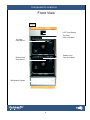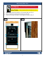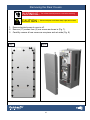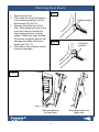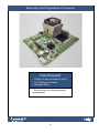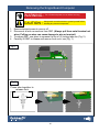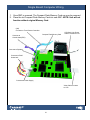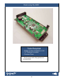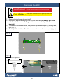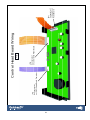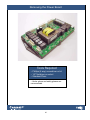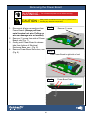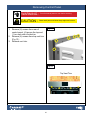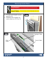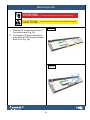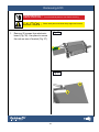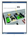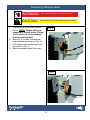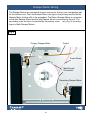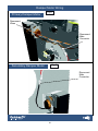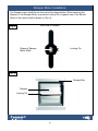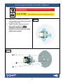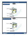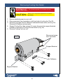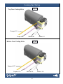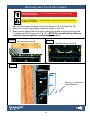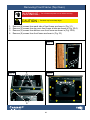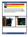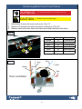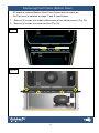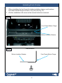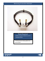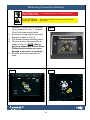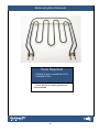
1
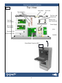
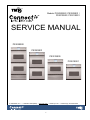
Models: PS302SS00 / PS302SS01 /
PS301SS00 / PS301SS01
SERVICE MANUAL
PS302SS00
PS302SS01
PS301SS00
PS301SS01
© 2006 TMIO, LLC • +1.800.881.TMIO (8646) • www.tmio.com • 1220A Flynn St. • Chattanooga, TN 37403 USA
Connect Io Service Manual
THE CONNECT IO SERVICE MANUAL CONTAINS INFORMATION THAT IS
NECESSARY FOR SERVICING THE TMIO INTELLIGENT OVEN MODELS:
PS302SS00 / PS302SS01
PS301SS00 / PS301SS01
THIS MANUAL IS DESIGNED TO BE USED BY QUALIFIED SERVICE PERSONNEL ONLY. DUE TO THE COMPLEXITY AND THE RISK OF HIGH VOLTAGE ELECTRICAL SHOCK, IT IS NOT RECOMMENDED CONSUMERS
PREFORM SERVICE ON THIS PRODUCT.
Previous data plate location
Current data plate location
Table of Contents
Data Plate Location ............................................................................................................... 2
TMIO Warranty ...................................................................................................................... 4
Section 1 Component Locations............................................................................................ 5
Section 2 Trim, Covers, and Door.......................................................................................... 9
Removing SideTrim.......................................................................................................... 10
Removing Electronic Enclosure Covers .......................................................................... 13
Removing Rear Covers.................................................................................................... 15
Removing Doors.............................................................................................................. 17
Section 3 Electronic Controls................................................................................................ 18
Removing SBC (Single Board Computer)........................................................................ 19
Removing ERC................................................................................................................. 22
Removing Power Boards.................................................................................................. 25
Removing Power Supply................................................................................................... 29
Removing Meat Probe Jack............................................................................................. 32
Removing TOD (Thermal Operating Device)................................................................... 36
Removing Oven Sensor................................................................................................... 38
Removing LCD Touch Screen ......................................................................................... 40
Removing Speaker .......................................................................................................... 45
Removing Light Transformer............................................................................................ 48
Section 4 Fans & Motors....................................................................................................... 51
Removing Damper Motor ................................................................................................ 52
Removing Convection Motor............................................................................................ 59
Removing Cooling Fan Motor........................................................................................... 64
Removing Door Lock Motor.............................................................................................. 67
Section 5 Refrigeration System............................................................................................. 74
Removing Built-in Refrigeratrion System......................................................................... 75
Removing Slide-in Refrigeration System ........................................................................ 80
Section 6 Heating Elements.................................................................................................. 83
Removing Convection Element........................................................................................ 84
Removing Broil Element................................................................................................... 86
Unit Safety Guidelines after Service...................................................................................... 88
“Connect Io” REFRIGERATOR-OVEN WARRANTY
FULL TWO-YEAR WARRANTY
For two years from the date of purchase, when this appliance is operated and maintained in accordance with
the instructions furnished with this product, TMIO, LLC will pay for replacement parts and repair labor to correct
defects in materials or workmanship. Service must be provided by a TMIO, LLC designated service company.
FIVE-YEAR FULL WARRANTY ON SEALED REFRIGERATION PARTS AS LISTED
For five years from the date of purchase, when this product is operated and maintained in accordance with the
instructions furnished with this product, TMIO, LLC will pay for replacement parts and repair costs to correct
defects in materials or workmanship in the sealed refrigeration system. The sealed refrigeration system consists of
the compressor, condenser, evaporator, dryer and all connecting tubing.
THIRD THROUGH FIFTH YEAR LIMITED WARRANTY
From the third through the fifth year from the date of original installation, TMIO, LLC will repair or replace the
following parts that prove to be defective in materials or workmanship. Labor to remove and replace defective
parts is not covered. TMIO, LLC recommends that you use TMIO, LLC authorized repair persons to perform such
services. The following parts are covered: electric heating elements, blower motors, and electronic oven control
boards (EOC’s).
LIMITATIONS
TMIO, LLC will not pay for:
1.
Service calls to correct the installation of your appliance, to instruct you how to use your appliance, to
replace house fuses or correct house wiring, or to replace owner-accessible light bulbs.
2.
Repairs when your appliance is used in other than normal, single-family household use.
3. Pickup and delivery. Your appliance is designed to be repaired in the home.
4. Damage resulting from accident, alteration, misuse, abuse, fire, flood, improper installation, acts of God or
use of products not approved by TMIO, LLC.
5. Repairs to parts or systems resulting from unauthorized modifications made to the appliance or the software
operating the appliance.
6. Repairs to parts or systems to correct any defect caused by negligence, accident or improper use,
maintenance, installation, service or repair.
7. Replacement parts or repair labor costs for units operated outside the United States and Canada.
8. Travel or transportation expenses for customers who reside in remote areas.
9. Any labor costs during the limited warranty period.
10.
Stainless Steel doors, panels, and frame repairs beyond 30 days for cosmetic defects
.
THE REMEDIES DESCRIBED ABOVE FOR EACH WARRANTY ARE THE ONLY ONES WHICH TMIO, LLC WILL
PROVIDE, EITHER UNDER THIS WARRANTY OR UNDER ANY WARRANTY ARISING BY OPERATION OF LAW.
TMIO, LLC WILL NOT BE RESPONSIBLE OR LIABLE FOR ANY CONSEQUENTIAL OR INCIDENTAL DAMAGES
ARISING FROM THE BREACH OF THIS WARRANTY OR ANY OTHER WARRANTY, WHETHER EXPRESS,
IMPLIED OR STATUTORY.
Some states do not allow the exclusion or limitation of incidental or consequential damages, so this exclusion or
limitation may not apply to you. This warranty gives you specific legal rights and you may also have other rights
which may vary from state to state.
For service questions visit the web at www.tmio.com or call 1-800-881-TMIO (8646).
Section 1
Section 1
Component Locations
Component Locations
Top View
Fig. 1
120V Outlet
Terminal Blocks
RJ45 Jack
Top Oven Light
Transformer
Bottom Oven
Light Transformer
Top Oven
Power Board
Power Supply
Bottom Oven
Power Board
ECR
Top Oven TOD
Bottom Oven TOD
Speaker
Single Board Computer (SBC)
Fig. 2
Component Locations
Fig. 3
RJ45 Jack
Rear View
120V Outlet
Top Oven
Cooling Fan
Top Oven
TOD
Top Oven
Inlet Damper
Motor
Top Oven
Convection Fan Motor
Top Oven
Return Damper Motor
Bottom Oven
Cooling Fan
Bottom Oven
TOD
Bottom Oven
Inlet Damper
Motor
Bottom Oven
Convection Fan Motor
Bottom Oven
Return Damper Motor
Component Locations
Front View
Fig. 4
LCD Touch Screen
Top Oven
Door Lock Motor
Top Oven
Oven Sensor
Bottom Oven
Door Lock Motor
Bottom Oven
Oven Sensor
Refrigeration System
Section 2
Section 2
Trim, Covers, and Door
Removal
Removing Side Trim
Tools Required
• Phillips (4 way) screwdriver or bit
• 1/4” Nutdriver or socket
• Standard Pliers
• Kevlar gloves and safety glasses are
recommended.
10
Removing Side Trim
WARNING : Turn off electrical power to oven before servicing.
CAUTION :
.
2.
3.
Sheet metal partscould have sharp edges and corners.
Remove (8) screws from side trim. (4) from each side, see (Fig. 1).
Pull unit forward to reveal side trim screws on each side.
Remove (2) screws from back of control panel as shown in (Fig. 2).
Fig. 1
Fig. 2
11
Removing Side Trim
WARNING : Turn off electrical power to oven before servicing.
CAUTION :
.
2.
Be careful when handling sheet metal parts could have
sharp edges and corners.
Starting from the bottom and moving upward remove the (6) screws and spacers
from each side trim, see Fig. 3). NOTE: There are two different size spacers on
side trim. The top and bottom side trim spacers are thinner. Use free hand to
hold trim to prevent from falling.
Remove trim from unit and set aside.
Fig. 3
12
Removing Electrical Enclosure Cover
Tools Required
• Phillips (4 way) screwdriver or bit
• 1/4” Nutdriver or socket
• Standard Pliers
• Kevlar gloves and safety glasses are
recommended.
13
Removing Electrical Enclosure Cover
WARNING : Turn off the electrical power to oven before servicing.
CAUTION :
.
2.
3.
4.
Sheet metal parts could have sharp edges and corners.
Ensure electrical power to oven has
been shut off.
Remove unit from enclosure, see
(Removing and Installing Unit in
Cabinet).
Remove (13) screws from top
electrical enclosure cover as shown
in (Fig. 4, Fig. 5).
Carefully lift cover and remove from
unit (Fig. 6).
Fig. 4
Fig. 6
Fig. 5
14
Removing the Rear Covers
Tools Required
• Phillips (4 way) screwdriver or bit
• 1/4” Nutdriver or socket
• Standard Pliers
• Kevlar gloves and safety glasses are
recommended.
15
Removing the Rear Covers
WARNING : Turn off the electrical power to oven before servicing.
CAUTION :
.
2.
3.
Sheet metal parts could have sharp edges and corners.
Ensure electrical power to oven is off.
Remove (17) screws from (4) rear covers as shown in (Fig. 7).
Carefully remove all rear covers as one-piece and set aside (Fig. 8).
Fig. 7
Fig. 8
16
Removing Oven Doors
.
2.
3.
4.
Fig. 9
Open the door fully.
Fully rotate the top of both latches
to the unlocked position until the
latches stop (Fig. 9 & 10).
Squarely facing the front of the
oven, firmly grasp each side of the
oven door near the handle and
begin closing the door to nearly
upright. When door stops closing,
lift the door up slightly and pull out,
swinging the bottom of the door
toward you (Fig. 11).
Place door on a protective surface
to prevent damages
Locked position
Fig. 10
Unlocked
position
Fig. 11
Hand grip position
for lower door
17
Hand grip position for
upper door
Section 3
Section 3
Electronic Control
Removal
18
Removing the Single Board Computer
Tools Required
• Phillips (4 way) screwdriver or bit
• 1/4” Nutdriver or socket
• Standard Pliers
• Kevlar gloves and safety glasses are
recommended.
19
Removing the Single Board Computer
WARNING : Turn off electrical power to oven before servicing.
CAUTION :
.
2.
3.
4.
Always touch a metal structure to ground yourself before
handling any electrical compnents
Ensure electrical power to oven is off.
Disconnect all wire connections from SBC. (Always pull from metal terminal not
wires. Pulling on wires can cause damage to wire or terminal).
To release SBC, use pliers to squeeze the top of (4) locking tabs see (Fig. 2).
Carefully lift SBC to release and remove from oven, see (Fig. 1).
Fig. 1
Fig. 2
Press tabs together to
release lock
20
Single Board Computer Wiring
.
2.
Once SBC is removed, The Compact Flash Memory Card can now be removed.
Place the old Compact Flash Memory Card into new SBC .NOTE: Unit will not
function without original Memory Card.
(J62)
Connects to Touch Screen Controller
Connects to
Control Head (ERC)
Compact Flash Memory Card
LCD Back Light Power
Cable Connects to LCD
Fig. 3
Connects to Speaker
Connects to RJ45
Outlet Jack
Connects to Power Supply
Video Cable connects
to LCD
21
Removing the ERC
Tools Required
• Phillips (4 way) screwdriver or bit
• 1/4” Nutdriver or socket
• Standard Pliers
• Kevlar gloves and safety glasses are
recommended.
22
Removing the ERC
WARNING : Turn off electrical power to oven before servicing.
CAUTION :
.
2.
3.
4.
Always touch a metal structure to ground yourself before
handling any electrical compnents
Ensure electrical power to oven is off.
Disconnect all wire connections from Control Head Board. (Always pull from
metal terminal not wire. Pulling on wire can cause damage to wire or
terminal).
To release Control Head Board, use pliers to squeeze the top of (4) locking tabs,
see (Fig. 5).
Carefully lift Control Head Board to release and remove from oven, see (Fig. 4).
Fig. 4
Fig. 5
Press tabs together to
release lock
23
24
(P3)
Connects to J61
on (SBC) Single Board Computer
(P5)
Connects to J1
on Lower Oven Power Board
Fig. 6
Control Head Board Wiring
(P7)
Connects to J1
on Upper Oven
Power Board
Removing the Power Board
Tools Required
• Phillips (4 way) screwdriver or bit
• 1/4” Nutdriver or socket
• Standard Pliers
• Kevlar gloves and safety glasses are
recommended.
25
Removing the Power Board
WARNING : Turn off electrical power to oven before servicing.
CAUTION :
.
2.
3.
4.
Always touch a metal structure to ground yourself before
handling any electrical components
Fig. 7
Disconnect all wire connections from
Power Board. (Always pull from
metal terminal not wire. Pulling on
wire can damage wire or terminal).
Remove (1) screw from side of Power
Board, see (Fig. 7).
Gently push Power Board to release
tabs from bottom of Electrical
Enclosure Base, see (Fig. 8).
Remove Power Board from oven, see
(Fig. 9).
Remove (1) screw
Fig. 8
Slide Power Board to right side of unit
Fig. 9
26
Power Board Tabs
Fig. 10
(P31)
(P33)
(P32)
Top Oven Power Board
(J1)
(P28)
(P27)
(P25)
(P21)
(P17)
(P24)
(P23)
(P8)
(P2)
(P3)
(P4)
(P9)
(P10)
(P1)
(P18)
(P11)
Label Wire Color
Wire #
Connects to
P1
Red
81
Terminal Block (L2)
P2
Purple
7
P3
Blue
P4
Label Wire Color Wire #
P28
Connects to
Brown
200
Damper Motor
Inner Broil Element
Grey
201
Damper Motor
8
Outer Broil Element
Orange
202
Damper Motor
Brown
9
Conv Element
Blue
203
Evaporator Sensor
P8
Red
90
Terminal Block (L2)
Blue
204
Evaporator Sensor
Orange
31
Cooling Fan High
Blue
13
Conv Low Speed
Red
32
Damper Motor Power
Black
3
Terminal Block (L1)
Red
50
Refrigeration
Yellow
39
Oven Lights
P9
Yellow
10
Bake Element
P10
Violet
51
Ref. Compressor
P11
Brown
52
Ref. Defrost Heater Strip
P17
Black
N/A
Top T.O.D
P18
Black
1
Terminal Block (L1)
P21
Black
5
Terminal Block (L1)
P23
White
24
Terminal Block (L1)
Purple
30
Cooling Fan Low
P24
Red
82
Rear T.O.D
Grey
17
Conv Fan High
Black
N/A
Terminal Block (L1)
Blue
28
Door Lock
Orange
N/A
Control Head
P25
Red
81
Rear T.O.D
P27
Yellow
16
Meat Probe Jack
Yellow
17
Meat Probe Jack
Brown
18
Door Lock
Orange
23
Door Lock
Red
22
Door Lock
Gray
21
Door Lock
Purple
N/A
Oven Sensor
Purple
N/A
Oven Sensor
P31
P32
P33
J1
27
Fig. 11
(P33)
(P31)
(P32)
Bottom Oven Power Board
(J1)
(P28)
(P27)
(P25)
(P21)
(P17)
(P24)
(P23)
(P8)
(P2)
(P3)
(P4)
(P9)
(P1)
(P18)
Label
Wire Color
Wire #
Connects To
P1
Red
92
Terminal Block (L2)
P2
Purple
133
Inner Broil Element
Label Wire Color Wire #
P28
Brown
Connects to
200
Damper Motor
Grey
201
Damper Motor
202
Damper Motor
P3
Blue
134
Outer Broil Element
Orange
P4
Brown
135
Conv Element
Blue
203
Sensor
P8
Red
93
Terminal Block (L2)
Blue
204
Sensor
P9
Yellow
136
Bake Element
Orange
107
Cooling Fan High
P17
Black
N/A
Top T.O.D
Blue
106
Conv Low Speed
P18
Black
56
Terminal Block (L1)
Red
123
Damper Motor Power
P21
Black
5
Terminal Block (L1)
P32
Black
124
Terminal Block (L1)
P23
White
57
Terminal Block (L1)
P33
Yellow
118
Oven Lights
P24
Red
88
Rear T.O.D
Purple
119
Cooling Fan Low
P25
Red
87
Rear T.O.D
P27
Yellow
108
Meat Probe Jack
Grey
120
Conv Fan High
Yellow
109
Meat Probe Jack
Black
121
Terminal Block (L1)
Brown
110
Door Lock
Blue
122
Control Head
Orange
111
Door Lock
Red
112
Door Lock
Gray
113
Door Lock
Purple
114
Oven Sensor
Purple
115
Oven Sensor
P31
28
Removing Power Supply
Tools Required
• Phillips (4 way) screwdriver or bit
• 1/4” Nutdriver or socket
• Standard Pliers
• Kevlar gloves and safety glasses are
recommended.
29
Removing Power Supply
WARNING : Turn off electrical power to oven before servicing.
CAUTION :
.
2.
3.
4.
5.
Always touch a metal structure to ground yourself before
handling any electrical compnents
Ensure electrical power to oven has been shut off.
Disconnect all wire connections from Power Supply. (Always pull from
connector not wires. Pulling on wire can damage wire or connector.)
Using pliers hold hex stand off legs to prevent from turning.
Remove (4) Phillips screws from corners of power supply, see (Fig. 12).
Remove power supply from oven.
Fig. 12
Secure with pliers to ensure standoff legs do not turn while
removing screws
30
31
(SK1)
Green ground wire connects to screw as shown.
White wire connects to COM terminal block.
Black wire connects to reset box located at refrigeration system.
Fig. 13
Power Supply Wiring Layout
(SK2)
Connects to (SBC) Single Board
Computer
All (5) wires connect together into one
female connector that connects to (SBC)
Single Board Computer
(SK201)
-S +S
Connects to (SBC) Single
Board Computer
Removing Meat Probe Jack
Tools Required
• Phillips (4 way) screwdriver or bit
• 1/4” Nutdriver or socket
• Standard Pliers
• Kevlar gloves and safety glasses are
recommended.
32
Removing Meat Probe Jack
WARNING : Turn off electrical power to oven before servicing.
CAUTION :
Ensure oven cavity and components are cool before
proceeding.
Fig. 14
.
2.
3.
4.
5.
Remove unit from cabinet.
Remove rear covers
Remove (2) screws from right side of
rear insulation retainer (Fig.14).
Remove (14) screws from side panel
(Fig.15).
Remove (2) screws from top vent trim
as shown in (Fig.16).
Fig. 15
Fig. 16
33
Removing Meat Probe Jack
WARNING : Turn off electrical power to oven before servicing.
CAUTION :
Ensure oven cavity and components are cool before
proceeding.
Fig. 17
.
2.
3.
4.
Carefully pull rear insualtion retainer
away from unit as shown in (Fig. 17).
Carefully lift up the right side of the
electronics enclosure to access (3)
screws in top of side panel (Fig. 18).
Remove (3) screws from side panel.
Carefully pull side panel out from rear
of unit, then slide side panel toward
rear of unit to remove (Fig.19).
Fig. 18
Fig. 19
34
Removing Meat Probe Jack
WARNING : Turn off electrical power to oven before servicing.
CAUTION :
.
2.
3.
4.
Ensure oven cavity and components are cool before
proceeding.
Fig. 20
Carefully remove Lock Nut from meat
probe jack (Fig. 20).
Pull meat probe jack through
insulation as shown in (Fig. 21).
Do not tear insulation.
Disconnect Jack Connector in rear of
unit (Fig. 22).
Pull connector through rear cover and
remove jack from unit.
Fig. 21
Fig. 22
35
Removing the T.O.D
Tools Required
• Phillips (4 way) screwdriver or bit
• 1/4” Nutdriver or socket
• Standard Pliers
• Kevlar gloves and safety glasses are
recommended.
36
Removing the T.O.D
WARNING : Turn off electrical power to oven before servicing.
CAUTION :
.
2.
3.
Always touch a metal structure to ground yourself before
handling any electrical components
Fig. 23
Disconnect (2) wires from T.O.D.
NOTE: Pull from terminal not wire
(Fig. 23).
Remove (2) screws from T.O.D.
(Fig. 24).
Remove T.O.D. (Fig. 25).
Fig. 25
Fig. 24
37
Removing Oven Sensor
Tools Required
• Phillips (4 way) screwdriver or bit
• 1/4” Nutdriver or socket
• Standard Pliers
• Kevlar gloves and safety glasses are
recommended.
38
Removing Oven Sensor
WARNING : Turn off electrical power to oven before servicing.
CAUTION :
.
2.
3.
4.
5.
Ensure oven cavity and components are cool before
proceeding.
Fig. 26
Remove (2) screws from Oven
Sensor Shield (Fig. 26).
Remove shield and set aside.
Pull Oven Sensor forward until
connectors are accessible through
opening in rear of oven (Fig. 27).
To disconnect the sensor connector,
press down the locking tab and pull
connectors apart (Fig. 28, Fig. 29).
Remove sensor from oven.
Oven Sensor Shield
Fig. 28
Fig. 27
Fig. 29
39
Press down
Removing LCD Touch Screen
Tools Required
• Phillips (4 way) screwdriver or bit
• 1/4” Nutdriver or socket
• Standard Pliers
• Kevlar gloves and safety glasses are
recommended.
40
Removing Control Panel
WARNING : Turn off electrical power to oven before servicing.
CAUTION :
.
2.
3.
Sheet metal parts could have sharp edges and corners.
Fig. 30
Remove (6) screws from rear of
control panel, (4) across the top and
(1) on each side of side trim.
Remove (4) screws from top vent trim
(Fig. 31).
Remove vent trim.
Fig. 31
Top Vent Trim
41
Removing Control Panel
WARNING : Turn off electrical power to oven before servicing.
CAUTION :
.
2.
Sheet metal parts could have sharp edges and corners.
Fig. 32
Tilt control panel forward to access
wires (Fig. 32).
Disconnect video, backlight, and
control cables from LCD (Fig. 33).
Fig. 33
Backlight Cable
Control Cable
Video
Cable
42
Removing LCD
WARNING : Turn off electrical power to oven before servicing.
CAUTION :
.
2.
Sheet metal parts could have sharp edges and corners.
Fig. 34
Remove (2) screws from bottom of
the control panel (Fig. 34).
To release LCD from control panel,
pull bottom of LCD brackets forward
and lift out (Fig. 35).
Fig. 35
43
Removing LCD
WARNING : Turn off electrical power to oven before servicing.
CAUTION :
.
Sheet metal parts could have sharp edges and corners.
Fig. 36
Remove (2) screws from electronic
board (Fig. 36). Use pliers to secure
the nuts on rear of bracket (Fig. 37).
Fig. 37
44
Removing Speaker
Tools Required
• Phillips (4 way ) screwdriver or bit
• 1/4” Nutdriver or socket
• Standard Pliers
• It’s recommended you wear kevlar
gloves and safety glasses.
45
Removing Speaker
WARNING : Turn off electrical power to oven before servicing.
CAUTION :
Always touch a metal structure to ground yourself before
handling any electrical components
Fig. 35
.
2.
3.
Disconnect wires from speaker as
shown in (Fig. 35). (Always pull from
metal terminal not wire. Pulling on
wire can damage wire or terminal).
Remove (4) screws from Speaker,
see (Fig. 36).
Remove Speaker from oven, see
(Fig. 37).
Fig. 37
Fig. 36
46
Speaker Wiring
Fig. 38
The Speaker is connected to Single Board Computer.
47
Removing Transformer
Tools Required
• Phillips (4 way) screwdriver or bit
• 1/4” Nutdriver or socket
• Standard Pliers
• Kevlar gloves and safety glasses are
recommended.
48
Removing Transformer
WARNING : Turn off electrical power to oven before servicing.
CAUTION :
.
2.
3.
Always touch a metal structure to ground yourself before
handling any electrical compnents
Disconnect all wire connections from Transformer. (Always pull from metal
terminal not wire. Pulling on wire can damage wire or terminal).
Remove (2) screws from each side of Transformer. Remove part from oven, see
(Fig. 39).
Remove wires from Transformer, see page 50 (Fig. 40, 41).
Fig. 39
49
Fig. 40
Top Oven Transformer
Wire # 45
Wire # 47
Wire # 44
Wire # 39
Fig. 41
Bottom Oven Transformer
Wire # 141
Wire # 116
Wire # 100
Wire # 118
50
Section 4
Section 4
Fan And Motor Removal
51
Removing Damper Motor
•
•
•
•
Tools Required
Phillips (4 way ) screwdriver or bit
1/4” Nutdriver or socket
Standard Pliers
2.5 mm Allen wrench
• Kevlar gloves and safety glasses are
recommended.
52
Removing Damper Motor
WARNING : Turn off electrical power to oven before servicing.
CAUTION :
.
2.
3.
Sheet metal parts could have sharp edges and corners.
First, loosen the Damper set pin inside
the damper box. Access the set pin
from front of the refrigeration vents
inside oven cavity, see (Fig. 1). If set
pin is not visible, the damper is not in
the correct position and pliers should
be used to grip damper shaft to rotate,
see (Fig. 2).
Damper should be positioned as shown
in (Fig. 3).
Use an allen wrench to loosen the set
screw through refrigeration slots inside
oven cavity. Pin only needs to be loose.
NOTE: Do not remove pin, doing so
could cause pin to fall and require
further disassembly of unit.
Fig. 2
Fig. 1
Fig. 3
Front View
53
Removing Damper Motor
WARNING : Turn off electrical power to oven before servicing.
CAUTION :
.
2.
3.
4.
Sheet metal parts could have sharp edges and corners.
Disconnect all wires from Damper
Motor. (NOTE: Always pull from
connectors, not the wires. Pulling
on the wires can cause damage
to wires and terminal.)
Remove (2) screws from damper
motor bracket as shown in (Fig. 4).
Pull damper motor away from duct
as shown in (Fig. 5).
Remove damper motor from oven.
Fig. 4
Fig. 5
54
Damper Motor Wiring
The Damper Motors are connected in pairs, one pair for the top oven and another pair
for the bottom oven. The Inlet Damper Motor (top right) is the primary and the Return
Damper Motor (bottom left) is the secondary. The Return Damper Motor is connected
to the Inlet Damper Motor and the Inlet Damper Motor is connected to the unit. The
secondary motor function is controlled by the primary motor , see (Fig. 6) for wiring
layout of both Damper Motors.
Fig. 6
Primary Damper Motor
Control
Power Wires
Male/Female
Connectors
Secondary Damper Motor
55
Damper Motor Wiring
Primary Damper Motor
Fig. 7
Disconnect
Wires
Disconnect
Male
Connector
Fig. 8
Secondary Damper Motor
Disconnect
Male
Connector
56
Damper Motor Installation
The Damper motor shaft fits into the end of the damp blades. When securing the
Damper to the Damper Motor, ensure the Locking Pin is against one of the flat surfaces on the motor shaft as shown in (Fig. 9).
Side view of Damper
Fig. 9
Shape of Damper
Motor Shaft
Locking Pin
Fig. 10
Damper Box
Damper
Locking Pin
57
Damper Motor Installation
When reinstalling the Damper Motor, align both Dampers to each other. If Dampers
are not in alignment the refrigeration may not properly function. Both motors must be
either open or closed as shown in (Fig. 11, 12). Also ensure the Damper are centered
in the damper box to prevent them from jams and causing misalignment. If the Damper looks like (Fig. 13), it is incorrect and adjustments must be made it to correct it (Fig.
11, 12).
Fig. 11
Fig. 13
Correct Alignment
Closed Position
Fig. 12
Incorrect Alignment
58
Open Position
Removing Convection Motor
Tools Required
• Phillips (4 way) screwdriver or bit
• 1/4” Nutdriver or socket
• Standard Pliers
• Kevlar gloves and safety glasses are
recommended.
59
Removing Convection Fan Cover
WARNING : Turn off electrical power to oven before servicing.
CAUTION :
.
2.
3.
4.
5.
Porcelain may have sharp edges.
Open oven door to access
Convection Fan Cover.
Remove (3) screws from Fan Cover,
see (Fig. 17). NOTE: Place free
hand on Fan Cover to prevent
from fall and possibly causing
damage.
Remove Cover from oven and set
aside.
To remove Fan Blades place one
hand on Fan Blades to prevent from
turning, then use Pliers or wrench
to turn nut counterclockwise to
loosen and remove.
Remove Fan Blades and set aside.
Fig. 17
Fig. 18
60
Removing Convection Motor
WARNING : Turn off electrical power to oven before servicing.
CAUTION :
.
2.
3.
Sheet metal parts could have sharp edges and corners.
Fig. 19
Remove (3) screws as shown
in (Fig. 19). NOTE: These screws
are the Convection Motors only
support caution is required when
removing the last screw to prevent
motor from falling from rear of unit.
Remove the wires from Convection
Fan Motor as shown in (Fig. 20).
Remove Convection Fan Motor from
unit and set aside (Fig. 21).
Fig. 20
Fig. 21
61
Removing Convection Insulation Retainer
WARNING : Turn off electrical power to oven before servicing.
CAUTION :
.
2.
Sheet metal parts could have sharp edges and corners.
Remove (3) screws from Motor to
remove Insulation Retainer as shown
in (Fig. 22, Fig. 23).
Install Insulation Retainer on new
Convection Fan Motor. NOTE:
Insulation Retainer must be
installed to ensure oven operates
safely and correctly.
Fig. 22
Fig. 23
62
Convection Motor Wiring
Top Oven Motor
Fig. 24
White #49
Blue #12
Grey #13
Bottom Oven Motor
Fig. 25
White #102
Blue #106
Grey #120
63
Removing Cooling Fan Motor
Tools Required
• Phillips (4 way) screwdriver or bit
• 1/4” Nutdriver or socket
• Standard Pliers
• Kevlar gloves and safety glasses are
recommended.
64
Removing Cooling Fan Motor
WARNING : Turn off electrical power to oven before servicing.
CAUTION :
.
2.
3.
4.
5.
Ensure oven c avity and components are cool before
proceeding.
Ensure electrical power to oven is off.
Disconnect wires from terminals on right hand side of cooling fan (Fig. 26).
Remove (2) screws from Air Deflector underneath blower motor, see (Fig. 26)
Remove Air Deflector and set aside.
Support Cooling Fan, then remove (4) screws from each fan support brackets
located on each side of Cooling Fan as shown in (Fig. 26).
Remove Cooling Fan from unit.
Disconnect wires
from terminals
Fig. 26
Support Bracket
Air Deflector
Support Bracket
65
Cooling Fan Wiring
Fig. 27
Top Oven Cooling Motor
Orange # 31
Purple # 30
Bottom Oven Cooling Motor
White # 49
White # 11
Fig. 28
Orange # 107
Purple # 119
White # 102
66
White # 101
Removing Door Lock Motor
Tools Required
• Phillips (4 way) screwdriver or bit
• 1/4” Nutdriver or socket
• Standard Pliers
• Kevlar gloves and safety glasses are
recommended.
67
Removing Vent Trim & Door Gasket
WARNING : Turn off electrical power to oven before servicing.
CAUTION :
.
2.
3.
Sheet metal parts could have sharp edges and corners.
Remove (4) screws from each vent trim as shown in (Fig. 28) and (Fig. 29).
Remove (1) screw from gasket retainer as shown in (Fig. 30).
Remove door gasket from front frame. Gently pull gasket at clip mounting points
to release from front frame, see (Fig. 30). (NOTE: Do not pull quickly, doing so
could rip clips from gasket causing damage to part. )
Fig. 28
Fig. 29
Top vent trim removal
Middle vent trim removal
Fig. 30
Remove (1) screw from
Gasket Retainer
68
Removing Front Frame (Top Oven)
WARNING : Turn off electrical power to oven before servicing.
CAUTION :
.
2.
3.
4.
Porcelain may have sharp edges.
Remove (4) screws from each side of front frame as shown in (Fig. 31).
Remove (2) screws from top oven front frame at tabs as shown in (Fig. 32 A).
Remove (2) screws from bottom oven front frame as shown in (Fig. 32 B).
Remove (9) screws from front frame as shown in (Fig. 33).
Fig. 31
Fig. 32
A
Fig. 33
B
69
Removing Front Frame (Top Oven)
WARNING : Turn off electrical power to oven before servicing.
CAUTION :
.
Porcelain may have sharp edges.
Grasp each side of top front frame and pull forward. Front frame should tilt
outward at the top enough to access door lock motor. Bottom of front frame
should remain behind bottom oven front frame tabs, see (Fig. 34). NOTE: If
front frame is pulled too far forward it is possible to chip the porcelain of
the top and bottom front frame where they are joined, see (Fig. 35). Do not
attempt to remove front frame from unit.
Fig. 35
Fig. 34
70
Removing Motor from Front Frame
WARNING : Turn off electrical power to oven before servicing.
CAUTION :
.
2.
3.
Porcelain may have sharp edges.
Disconnect all wires from door lock motor (Fig. 37).
Remove (2) screws from door lock motor as shown in (Fig. 36).
Remove door lock motor from front frame and install new door lock motor.
Fig. 36
Wire Color
Orange
Brown
Grey
Blue
White
Red
Fig. 37
Blue
Grey
Orange
Wire #
23
18
21
28
29
22
White
Brown
Red
Door Lock Motor
71
Connects To
Power Board
Power Board
Power Board
Power Board
Terminal Block
Power Board
Removing Front Frame (Bottom Oven)
All steps to remove Bottom Oven Front Frame are the same as
the Top oven in addition to steps 1 and 2 listed below.
.
2.
Remove (2) screws from middle airflow cover to front frame shown in (Fig. 38).
Remove (4) screws from lower vent trim (Fig. 39).
Fig. 38
Fig. 39
72
Installing Front Frame
.
2.
When reinstalling the front frame the bottom insulation retainer must be above
front frame bottom flange as shown in (Fig. 40) and (Fig. 41).
All other installation is the same as the removal instructions reversed.
Fig. 40
Front Frame Bottom Flange
Bottom Insulation Retainer
Fig. 41
Side Illustration
Bottom Insulation Retainer
Front Frame Bottom Flange
73
Section 1
Section 5
Refrigeration
74
Removing the Refrigeration System
Tools Required
• Phillips (4 way) screwdriver or bit
• 1/4” Nutdriver or socket
• Standard Pliers
• Kevlar gloves and safety glasses are
recommended.
75
Removing the Refrigeration System
WARNING : Turn off electrical power to oven before servicing.
CAUTION :
.
2.
3.
Sheet metal parts could have sharp edges and corners.
Ensure electrical power to oven is off.
To simplify illustrations, insulation on
refrigeration ducts are not shown.
Carefully peel back insulation around
refrigeration duct transition boxes
to reveal (16) screws. Do not to tear
insulation.
Remove (16) screws from the
refrigeration transition boxes as shown
in (Fig. 2).
Fig. 1
Inlet Refrigeration
Duct
Return Refrigeration
Duct
Fig. 2
Inlet Refrigeration
Transition Box
Return Refrigeration
Transition Box
76
Disconnecting the Reset Switch Wiring
WARNING : Turn off electrical power to oven before servicing.
CAUTION :
.
2.
3.
4.
5.
Always touch a metal structure to ground yourself before
handling any electrical components
Ensure electrical power to oven is off.
(4) wires coming from the refrigeration system are for the reset switch located on
front of the refrigeration unit. These (4) wires run all the way up the back of unit
to the top of electronic enclosure. These (4) wires must be disconnected as
shown here. Do not cut or splice these wires. Doing so could be unsafe to
you and the customer.
Disconnect (4) wires from their locations shown in (Fig. 3).
Remove female connector from the power supply board connected by the black
wire. The green wire is secured with a ground screw to power supply board. The
white wire is connected to terminal block. For wiring info of the Power Supply, see
pg. 31
Remove (4) wires from the main wiring harness which runs from the bottom and
top ovens to the top of the unit.
Top Electrical Enclosure
Fig. 3
Black wire connects to
power supply board
Red Wire connects
to (L1) terminal
block
Black wire connects
to 120v outlet
77
Red wire connects to (L2)
terminal block
Disconnecting Wiring at Rear of Unit
WARNING : Turn off electrical power to oven before servicing.
CAUTION :
.
2.
3.
4.
When disconnecting wires or wire connectors, do not
pull on wire. Only pull from connector or terminal.
Ensure electrical power to oven is off.
Disconnect (4) wire male and female connectors, see (Fig. 4) 1.
Disconnect sensor male and female connectors, see (Fig. 4) 2.
Loose white wire is not used, see (Fig. 4) 3.
Fig. 4
Bottom Rear of Unit
1
3
Loose white wire is not
used
Refrigeration main
power wires
78
2
Refrigeration
Sensor connectors
Removing Refrigeration System from Base
WARNING :
CAUTION :
.
2.
3.
4.
Turn off electrical power to oven before servicing.
Refrigeration System is heavy. Use proper lifting
techniques when moving system.
Remove Refrigeration Panel,
Remove (2) screws from front refrigeration bracket as shown in (Fig. 5), then
remove bracket.
Pulling from the front of the refrigeration system, the unit will begin to side out.
Remove refrigeration system from unit and continue with installation of new
system.
Fig. 5
Fig. 6
Remove (2) screws
79
Removing the Slide-in Refrigeration System
WARNING : Turn off electrical power to oven before servicing.
CAUTION :
Sheet metal parts could have sharp edges and corners.
Fig. 7
.
2.
3.
4.
Remove Refrigeration panel from
front of unit. (Fig .7)
Remove (1) screw from wire
connector box located at top of
Refrigeration unit (Fig.8).
Remove (4) screws from bottom
vent trim.Remove trim and set aside
(Fig.9).
Remove (2) screws from refrigeration
mounting bracket. Remove bracket
and set aside (Fig.9).
Fig. 9
Fig. 8
80
Removing the Refrigeration System
WARNING : Turn off electrical power to oven before servicing.
CAUTION :
Sheet metal parts could have sharp edges and corners.
Fig. 10
.
2.
Disconnect both connectors in
refrigeration unit (Fig.10). Push
connectors through opening into the
upper part of the base.
Pull refrigeration unit forward to
remove from unit. NOTE: Use caution
when lifting refrigeration unit, unit
is heavy.
Fig. 11
81
Installing New Refrigeration System
WARNING :
CAUTION :
.
2.
3.
4.
5.
6.
Turn off electrical power to oven before servicing.
Refrigeration System is heavy. Use proper lifting
techniques when moving system.
When installing new Refrigeration System take the same steps as the removal
process only in reverse. Any other differences are listed below and should be
followed to ensure proper installation of system.
Once the new system is in place and secured to unit, ensure gaskets around duct
transition boxes are sealed.
Duct and transition box insulation must be positioned to their original location and
sealed with Polyken® 360-17 FOILMASTER™ Sealant U.L. 723 approved tape,
or equivalent. Standard foil tape should not be used.
Double-check all wire connections to ensure they are secured and routed
properly. Avoid pinching or damaging wires.
When reinstalling rear covers, ensure there are no wires pinched between covers
and unit.
Replace Refrigeration panel, see (Fig. 12).
Fig. 12
Female locking tab
Male locking tab
82
Section 6
Heating Elements
83
Removing Convection Element
Tools Required
• Phillips (4 way) screwdriver or bit
• Standard Pliers
• Kevlar gloves and safety glasses are
recommended.
84
Removing Convection Element
WARNING : Turn off electrical power to oven before servicing.
CAUTION :
.
2.
3.
4.
5.
Ensure oven cavity and components are cool before
proceeding.
Remove (3) screws from Convection
Cover as shown in (Fig. 1). Remove
Cover from oven and set aside.
Remove (2) screws from Convection
Element as show in (Fig. 2).
Pull element forward revealing wires.
Disconnect wires from terminals as
shown in (Fig. 3). (NOTE: Always
pull from connectors, not the wires.
Pulling from the wires can cause
damage to wire and / or terminal.)
Remove convection element from
oven.
Fig. 1
Fig. 2
Fig. 3
85
Removing Broil Element
Tools Required
• Phillips (4 way) screwdriver or bit
• Standard Pliers
• Kevlar gloves and safety glasses are
recommended.
86
Removing Broil Element
WARNING : Turn off electrical power to oven before servicing.
CAUTION :
.
2.
3.
4.
5.
Ensure oven cavity and components are cool before
proceeding.
Fig. 4
Remove (2) screws from Broil
Element supports and (2) screws
from rear support brackets, see
(Fig. 4). NOTE: Place free hand on
Element to prevent from falling.
Pull Element forward to reveal wires.
NOTE: Pulling quickly could cause
wires to disconnect from terminals
and fall behind unit.
Tilt front of Element down and let it
rest on the bottom of the oven cavity,
see (Fig. 5).
Disconnect wires from terminals.
(NOTE: Always pull from
connectors, not the wires. Pulling
from the wires can cause damage
to wire and terminal.)
Remove Element from oven.
Fig. 5
87
Final Safety Check
WARNING
Once Service to oven is complete, but before applying power
to the oven, do the following: Use a Hipot Tester to ensure the wire
terminals are not loose or touching bare metal. Also ensure there
were no wires pinched or crushed during repair.
When Hipot testing the oven, it must be completely
assembled, with all covers and guards in their correct positions. The
recommended Hipot settings are listed below:
•
•
•
•
Voltage – 1.25 (1250 volts)
Current – 10.00 (10 mill amps)
Dwell – 1.0 (1 second)
Ramp/Pulse – 0.1 (1 second)
Fig. A
NOTE: Test each wire
individually. Connect Hipot
lead to White wire (Neutral),
connect another to chassis of
oven and test. If test passes,
then repeat test with the Red
(L2), and Black (L1) wire. See
(Fig. A).
Test 1
Conduit
Cable
Test 2
Test 3
If Oven passes Hipot test, proceed with functional test of oven. If
covers or guards are removed at any time, oven must be Hipot tested
once again to ensure safety, to you and the customer.
88