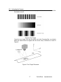
1
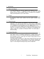
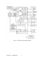
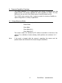
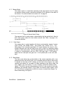
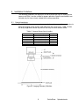
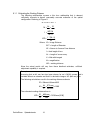
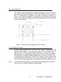
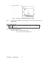
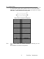
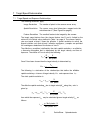
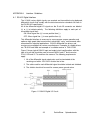
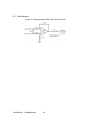
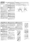
Digital Imaging
LC3000-Series Camera Instruction Manual
I N S T R U C T I O N
Imaging
M A N U A L
PerkinElmer Optoelectronics
2175 Mission College Blvd.
Santa Clara, CA 95054
Tel: 408-565-0830
Toll Free: 800-775-OPTO (6786)
Fax: 408-565-0703
E-Mail: [email protected]
http://www.perkinelmer.com
www .perkinelmer .com/opto
055-0458-MAN Rev. C
Copyrights, Patents and Trademark Credits
PerkinElmer, the PerkinElmer Logo and the stylized P are trademarks of PerkinElmer, Inc.
Reticon is a registered trademark of PerkinElmer, Inc.
Warranty
Seller warrants that the article to be delivered under this order will be free from defects in
material and workmanship under normal use and service for a period of one year from date of
shipment. The liability of Seller under this warranty is limited solely to replacing or repairing
or issuing credit (at the discretion of Seller) for such products that become defective during
the warranty period. In order to permit Seller to properly administer this warranty, Buyer
shall:
(1)
Notify Seller promptly in writing of any claims;
(2)
Not open the camera cover as there are no user serviceable parts inside.
(2)
Provide Seller with an opportunity to inspect and test the products
claimed to be defective. Such inspection may be on customer's
premises or Seller may request return of such products at customer's
expense. Such expense will subsequently be reimbursed to customer if
the product is found to be defective; and
(3)
Shall not return any product without prior return authorization from
Seller.
If a returned product is found to be out of warranty or found to be within the applicable
specification, Buyer shall pay an evaluation and handling charge, in addition to possible repair
and/or replacement costs. Seller will notify Buyer of the amount of said evaluation and
handling charges at the time the return authorization is issued. Seller will inform Buyer of
related repair and/or replacement costs and request authorization before incurring such costs.
Buyer shall identify all returned material with Seller's invoice number, under which material
has been received. If more than one invoice applies, material shall be clearly segregated and
identified by applicable invoice numbers. Adjustment is contingent upon Seller's examination
of product, disclosing that apparent defects have not been caused by Buyer's misuse, abuse,
improper installation or application, repair, alteration, accident or negligence in use, storage,
transportation or handling. In no event shall Seller be liable to Buyer for loss of profits, loss or
use, or damages of any kind based upon a claim for breach of warranty.
The aforementioned provision does not extend the original warranty period of any article
which has been repaired or replaced by Seller.
SELLER MAKES NO OTHER WARRANTIES, EXPRESS OR IMPLIED, AND
SPECIFICALLY, SELLER MAKES NO WARRANTY OF MERCHANTABILITY OF
FITNESS FOR A PARTICULAR PURPOSE.
PerkinElmer
Optoelectronics
ii
Table of Contents
1 I NTRODUCTION ................................
................................
................................
..............1
1.1
1.2
1.3
1.4
WHAT’ S I N THIS MANUAL ................................
................................
...................1
PURPOSE................................
................................
................................
............1
PRODUCTOVERVIEW ................................
................................
..........................
1
FUNCTIONAL DESCRIPTION................................
................................
..................1
2 T YPICAL I NSTALLATION ................................
................................
................................
3
3 RECEIVING AND I NSPECTING YOUR CAMERA ................................
..............................
4
3.1 UNPACKING Y OUR CAMERA ................................
................................
................4
3.2 CUSTOMERSUPPLIED COMPONENTS................................
................................
....4
4 CAMERA OPERATION OVERVIEW ................................
................................
.................5
4.1 CAMERA EXPOSUREM ODES................................
................................
................5
4.1.1 Master Mode................................
................................
............................
6
4.1.1.1 Data Output................................
................................
..................6
4.1.2 Slave Mode................................
................................
..............................
6
4.1.2.1 Exposure Control
................................
................................
..........7
4.1.2.2 Slave Mode Data Output
................................
...............................
7
4.1.3 Alt Slave Mode .1...............................
................................
......................
8
4.1.4 Alt Slave Mode .2...............................
................................
......................
8
4.1.4.1 Alt Slave Mode 2 Exposure
................................
...........................
8
4.1.5 Line Period Limits................................
................................
....................8
5 I NSTALLATION G UIDELINES ................................
................................
..........................
9
5.1 OPTICAL INTERFACING................................
................................
........................
9
5.1.1 Estimating the Working Distance
................................
.............................
10
5.2 L ENS A TTACHMENT ................................
................................
..........................
11
5.3 M OUNTING THE CAMERA ................................
................................
..................11
5.4 CONNECTING POWER ................................
................................
........................
12
5.4.1 Power Supply Requirements
................................
................................
....12
5.5 I NTERFACE CABLING ................................
................................
.........................
13
5.6 FRAME GRABBER I NTERFACEGUIDELINES ................................
.........................
14
5.7 CLEANING THE SENSOR................................
................................
.....................14
6 CAMERA SETUP................................
................................
................................
............15
6.1 PREPARING FOR THEINSTALLATION ................................
................................
...15
6.2 I NSTALLING THE CAMERA ................................
................................
.................15
6.2.1 Tripod Mounting................................
................................
.....................16
6.3 A CTIVATING THE CAMERA ................................
................................
................17
6.4 CAMERA CONTROL ................................
................................
...........................
18
6.4.1 Camera Operating Mode Selection
................................
...........................
18
6.4.2 Video Gain................................
................................
.............................
18
6.4.3 Video Offset................................
................................
..........................
19
6.4.4 Camera Powerup
................................
................................
....................19
6.4.5 Focusing the Camera
................................
................................
..............19
6.4.6 Verifying Camera Gain Control
................................
...............................
19
iii
PerkinElmer
Optoelectronics
6.5 V ERIFYING SLAVE M ODE OPERATION ................................
................................
20
7 TARGET SPEED D ETERMINATION ................................
................................
...............21
7.1 TARGET SPEED ANDEXPOSURERELATIONSHIPS................................
.................21
7.2 SAMPLE IMAGING SETUP................................
................................
...................22
8 TROUBLESHOOTING ................................
................................
................................
.....23
8.1 TROUBLESHOOTINGCHECK L IST ................................
................................
.......23
8.2 RMA (RETURN MATERIAL AUTHORIZATION)................................
.....................23
8.3 CONTACTING CUSTOMERSUPPORT................................
................................
....24
APPENDIX A
I NTERFACE G UIDELINES ................................
................................
.......25
A.1 RS-422 DIGITAL I NTERFACE................................
................................
..............25
A.2 V IDEO RECEIVER................................
................................
...............................
26
List of Figures
Figure 1 LC3000 Series Camera Block Diagram
................................
................................
...2
Figure 2 Typical Machine Vision Environment
................................
................................
.....3
Figure 3 Master Mode Timing
................................
................................
..............................
6
Figure 4 Slave Mode Timing
................................
................................
................................
7
Figure 5 Imaging Geometry Definition
................................
................................
.................9
Figure 6 Camera Front Face Attachment Point Definition
................................
...................11
Figure 7 LC3000 Series Camera Mounting Hole Location
................................
..................12
Figure 8 Test Target
................................
................................
................................
...........17
Figure 9 Test Target Placement
................................
................................
...........................
17
Figure 10 Camera Control DIP switch Location
................................
................................
..18
Figure 11 RS-422 Digital I/O Circuit
................................
................................
..................25
Figure 12 Recommended Video Line Receiver Circuit
................................
........................
26
List of Tables
Table 1
Table 2
Table 3
Table 4
Table 5
Table 6
Line Period Limit Definition
................................
................................
....................
8
Camera Sensor Array Lengths
................................
................................
..................9
RS-422 Connector Pin Assignment
................................
................................
........13
Camera Operating Mode Selection
................................
................................
.........18
Video Gain Selection
................................
................................
.............................
18
Video Offset Selection
................................
................................
...........................
19
PerkinElmer
Optoelectronics
iv
1 Introduction
1.1
What’s In this Manual
This manual describes the receiving, unpacking and inspection of your LC3000
series camera. Included is a operational overview that defines the camera
operation and the controls provided. Guidance is provided for the installation,
setup and initial operation of your LC3000 camera.
1.2
Purpose
To provide machine vision system engineers and technicians a definitive guide
for integrating LC3000 series cameras into their specific machine vision
application.
1.3
Product Overview
The LC3000 series cameras are designed for linear line scan image capture
applications. 512, 1024 and 2048 pixel line scan image capture is offered at 10,
or 20 megapixels/second depending on the camera model selected. Each camera
uses a PerkinElmer P-series photodiode linear array with
mm 14
pixel pitch at a 14
mm aperture. This provides a 54dB dynamic range over a spectral range of 350 to
1000 nm. All camera control functions are selected by corresponding DIP
switches. Digital I/O is provided as differential RS-422. The video output is
differential analog.
1.4
Functional Description
The LC3000 series cameras incorporate high performance, high resolution line
scan image sensors. (PerkinElmer Optoelectronics Imaging Systems parts
RL0512PAG, RL1024PAG, or RL2048PAG) featuring pinned photodiode pixels.
Each photodiode converts incident light into discrete charge packets that are
converted to an analog voltage.
The analog voltage is processed as a single channel sampled and held raster order
analog video data signal. Analog processing circuitry provides adjustable gain
and offset levels allowing the accommodation of unique lighting requirements.
Figure 1 is a block diagram illustrating the major camera components.
1
PerkinElmer
Optoelectronics
Figure 1 LC3000 Series Camera Block Diagram
PerkinElmer
Optoelectronics
2
2 Typical Installation
Figure 2 illustrates a typical machine vision installation showing the major
system components and defines the coordinate system used throughout this
manual.
Figure 2 Typical Machine Vision Environment
3
PerkinElmer
Optoelectronics
3 Receiving and Inspecting Your Camera
3.1
Unpacking Your Camera
Inspect the received shipping container for any damage. If a shipping container
shows visible signs of damage, it should be retained until all of the contents have
been checked for completeness and absence of damage. Unpack the received
shipping container and account for each item listed on the accompanying packing
list. Visually inspect each item for absence of damage. In the event of damage,
notify the shipper and the PerkinElmer shipping department. Retain all shipping
materials for shipper inspection.
Your first LC3000 shipping container in accordance with the enclosed packing
list should contain the following:
1. LC3000 camera in static resistant envelope with unbroken seal.
2. Users Manual
3. Tripod Mount
3.2
Customer Supplied Components
The following are components, not supplied with the camera, that are required for
installation and operation of the camera in your particular machine vision
environment.
1. Camera Lens + Extender (Available by contacting PerkinElmer)
2. Camera mounting hardware (Tripod mounting block included)
3. PC with Frame Grabber and digital I/O
4. Power Supply
5. Interface Cable (Available by contacting PerkinElmer)
6. Web illumination source
7. Web speed and light control.
This is not a complete list of items that may be required for your specific
application, but represents a minimum required to verify camera operation.
Note:
The majority of the customer supplied items are peculiar to each installation and
may require custom fabrication. Guidelines for fabrication are provided in section
6.2 on page15.
PerkinElmer
Optoelectronics
4
4 Camera Operation Overview
The camera operation is a 2 stage process that consists of exposure and data
output transfer. This process operates the same regardless of mode. The only
differences are the events that initiate exposure and data output transfer.
The LC3000 series cameras offer 4 exposure modes for maximum flexibility to
capture image data in a variety of applications.
4.1
Camera Exposure Modes
The following exposure modes are provided:
·
Master Mode
·
Slave Mode
·
Slave Mode (Alt 1)
·
Slave Mode (Alt 2)
The camera modes are selected by DIP switches accessible on the back of the
camera. For a definition of mode selecting switch positions see section on 6.4.1
page18.
Note:
If the mode is changed while the camera is operating, the camera must be
powered down and restarted for the mode change to take effect.
5
PerkinElmer
Optoelectronics
4.1.1 Master Mode
The master mode is a stand-alone operating mode that requires only DC power
for operation. Master mode is selected on the bank of DIP switches on the back of
the camera. For mode selection see section 6.4.1 on page 18
.
Figure 3 Master Mode Timing
The exposure time in master mode is determined by the line period that is fixed at
N+41 clock cycles, where N is the number of pixels. See Table 1 on page 8 for
line period definition
4.1.1.1 Data Output
The analog video is output together with three synchronization signals: Camera
Clock (CCLK), Line Enable (LEN) , and Camera Line Transfer (CLT). The
falling edge of the internally generated CLT signal indicates the start of a line
readout sequence and may be used by the user’s system for controlling strobes,
shutters or other accessories. The LEN signal brackets the valid analog video that
is output in synchronization with the CCLK. LEN goes high 1 CCLK period
before the first valid pixel and goes low 1 CCLK period prior to the last valid
pixel.
4.1.2 Slave Mode
The slave mode allows the synchronization of the camera operation with a user
generated master clock MCLK and a user controlled exposure period. Slave mode
is selected on the bank of DIP switches on the back of the camera. For mode
selection see section 6.4.1 on page 18. When operating in the Slave Mode, the
user supplies LR (Line Reset), LT (Line Transfer) and MCLK (Master clock)
signals. The MCLK may be selected between 20 kHz to the maximum clock rate
allowed for the selected camera. In this mode, the camera output signals CCLK,
CLT and LEN are synchronized to MCLK to assure a locked video output. For
Slave mode timing, see Figure 4.
PerkinElmer
Optoelectronics
6
4.1.2.1 Exposure Control
Slave mode camera exposure is determined by the LR and LT signals which must
be timed with MCLK. The exposure time is defined as the time between the
rising edge of the LR signal and the rising edge of the LT signal. The LR signal
must be held active low (ON) for a minimum of 4 clock cycles and must be
inactive high (OFF) for a minimum of 4 clock cycles prior to the LT signal rising
edge. The LT signal must remain on (High) for at least 2 clock cycles and may
remain ON until 2 clock cycles prior to the next line transfer. Because there are
extra stages in the CCD readout register there must be at least N+41 MCLK
cycles between successive LT commands.
Figure 4 Slave Mode Timing
4.1.2.2 Slave Mode Data Output
The data output timing in the slave mode is identical to that of the master mode
taking note, however, that the CCLK, CLT and LEN signals are synchronized to
the externally applied MCLK.
Note 1.
Since the camera electronics stores a video line in memory prior to sending it to
the output, then when operating in the slave mode, the first line output after the
first LT has been issued is not valid.
Note 2.
CCLK – Analog video data can be sampled or digitized using the falling edge of
the CCLK signal, however the receive circuit propagation delays must be
carefully managed in the systems design.
7
PerkinElmer
Optoelectronics
4.1.3 Alt Slave Mode 1
Alt Slave Mode 1 operates similarly to the Slave Mode except that the camera
operates on the internal camera clock CCLK (The basic camera model clock rate)
while the exposure is determined by the externally applied LR and LT signals.
There must be at least N+41 CCLK cycles between successive LT commands.
4.1.4 Alt Slave Mode 2
In Alt Slave Mode 2 the camera accepts a user supplied master clock MCLK and
line transfer signal LT. The LR signal in this mode is ignored.
4.1.4.1 Alt Slave Mode 2 Exposure
The exposure in Alt Slave Mode 2 is determined by the period of LT. There must
be at least N+41 CCLK cycles between successive LT commands.
4.1.5 Line Period Limits
Table 1 Line Period Limit Definition
PerkinElmer
Model
# Pixels
Clock
LC3011
LC3012
LC3013
LC3021
LC3022
LC3023
512
1024
2048
512
1024
2048
10 MHz
10 MHz
10 MHz
20 MHz
20 MHz
20 MHz
Optoelectronics
8
Max Line Scan Min. Line
Rate
Scan Period
18,083 L/sec
55.3 msec
9,389 L/sec
106.5msec
4,787 L/sec
208.9 msec
36,166 L/sec
27.6 msec
18,779 L/sec
53.2 msec
9,574 L/Sec
104.4 msec
5 Installation Guidelines
The following guidelines are offered as an aid to permit the user for setting up the
camera such that it can be verified for proper operation. Specific requirements are
included only for items closely related to the camera operation.
5.1
Optical Interfacing
The LC3000 series cameras require properly chosen lenses and lens extenders to
allow the imaging of the chosen web width onto the sensor array. Table 2 shows
the array length and number of pixels on the array for each camera model.
Table 2 Camera Sensor Array Lengths
Camera Model
LC3011
LC3012
LC3013
LC3021
LC3022
LC3023
Active Array Length (AL)
0.28" (7.168 mm)
0.56" (14.336 mm)
1.13" (28.672 mm)
0.28" (7.168 mm)
0.56" (14.336 mm)
1.13" (28.672 mm)
Active Pixels
512
1024
2048
512
1024
2048
Figure 5 Imaging Geometry Definition
9
PerkinElmer
Optoelectronics
5.1.1 Estimating the Working Distance
The following relationships assume a thin lens relationship that is deemed
sufficiently accurate to permit reasonably accurate estimates of the optical
configuration. Referring to Figure 5:
ID = EXT + AF + f
M =
f =
WD =
AL ID
=
X WD
WD * M
M +1
f * ( M + 1)
M
Where: ID = Image Distance
EXT = Length of Extender
AF = Sensor to Camera Face distance
f = focal length of lens
AL = Length of sensor array
X = Web with imaged
M = magnification
WD = working distance
Since the actual results will vary from these idealized estimates, sufficient
adjustment capability is required.
Example
Assuming that an 80 mm lens has been chosen for an LC30XX camera and is
installed without an extender and that it is desired to image a 36” (882 mm) web.
The following calculations result in the working distance estimate:
ID = 5.8 mm+ 80mm= 85.5
M =
AL 57.3 mm
=
= 0.065
X
882mm
The estimated working distance then is:
WD =
PerkinElmer
Optoelectronics
ID 85.5 mm
=
= 1315.4 mm ( 51.8" )
M
.065
10
5.2
Lens Attachment
The LC3000 series cameras provide threaded mounting holes on the front face of
the cameras to allow the attachment of custom lens adapters. The lens mount is a
M42 x 1 (Pentax) thread. PerkinElmer can provide such optical components as
lenses, C and F style lens adapters, extension tubes, and focusing systems. Figure
6 shows the location of mounting holes and registration holes for the attachment
of custom lens adapters.
Figure 6 Camera Front Face Attachment Point Definition
5.3
Mounting the Camera
Camera mounting distance from the object to be imaged is determined by the
required object width X, the camera array size and the selected lens and
extension. See section
5.1 for some general guidelines for physically locating
your camera for your application. Mounting the camera requires the supplied
mounting plate or customer supplied adapter. Figure 7 shows the location of the
mounting holes for attaching the camera to the mounting surface, specifies the
mounting hole thread and defines the sensor optical distance setback AF (5.8
mm). The same mounting provisions are provided on each of the camera 4 sides.
Note:
To install the mounting plate you must remove the two phillips head screws first.
These screws are reused to attach the mounting plate.
11
PerkinElmer
Optoelectronics
Figure 7 LC3000 Series Camera Mounting Hole Location
Note:
5.4
For best thermal stability, mount the camera to a flat metal surface using the
faceplate holes.
Connecting Power
Warning: It is the buyers responsibility to comply with all applicable code
requirements.
5.4.1 Power Supply Requirements
The power supply must provide at the camera:
+11.4 to +25.2 VDC, 500 mA @ 12V DC
PerkinElmer
Optoelectronics
12
5.5
Interface Cabling
The signal interface cable supports an RS-422 interface to receive the external
LT, LR and MCLK signals and to output the LEN, CLT and CCLK signals.
Additionally the cable connects power to the camera and provides the analog
video output. Contact PerkinElmer for cabling options.
Table 3 RS-422 Connector Pin Assignment
Signal
N/C
N/C
CCLK+
MCLKN/C
N/C
CLT+
LENN/C
LR+
N/C
VIDEOPOWER+
POWER RETURN
MCLK+
CCLKLT+
LTCLTLEN+
N/C
LRN/C
VIDEO+
N/C
Note:
Pin
1
2
3
4
5
6
7
8
9
10
11
12
13
14
15
16
17
18
19
20
21
22
23
24
25
Description
No Connection
No Connection
Camera Clock +
Master Clock No Connection
No Connection
Camera Line Transfer +
Line Enable No Connection
Line Reset +
No Connection
Analog Video Input DC Power +
Input Power Common
Master Clock +
Camera Clock External Line Transfer +
External Line Transfer Camera Line TransferLine Enable +
No Connection
Line ResetNo Connection
Analog Video +
No Connection
Always observe proper EMI shielding configuration if fabricating your own
cable.
See APPENDIX A for interface circuit guidelines.
13
PerkinElmer
Optoelectronics
5.6
Frame Grabber Interface Guidelines
The LC3000 series cameras have been designed for use with several brands of
frame grabber. It is the users responsibility to select a frame grabber that is
specific to the application being served and to provide any signal conditioning
required to accept the differential analog video and support the RS-422 interface
signals. When choosing a frame grabber, the following points must be observed:
1. Camera model (for number of pixels in sensor array).
2. Camera exposure mode. Slave modes require external input signals. See
section 4.1.2 on page 6.
3. The frame grabber must be able to accept differential analog video.
Contact PerkinElmer for a list of recommended frame grabber vendors.
5.7
Cleaning the Sensor
Should the sensor become dirty the user can clean the face taking care to use
Isopropyl Alcohol only.
Caution: Do not allow any of the cleaning solution to contact any
internal components, sensor pins or connector pins.
Caution: Do not remove the cover over the sensor, or the faceplate.
There are no user serviceable parts inside.
PerkinElmer
Optoelectronics
14
6 Camera Setup
This section provides a generalized procedure for installing, configuring and activating
your camera. Since every application is different, only suggested steps for a logical
sequence to get the camera running are listed. It is assumed that you have familiarized
yourself with the camera exposure and data output modes as described in4.1on
section
page5.
6.1
Preparing for the Installation
It is assumed that you have defined and implemented a machine vision
environment for your application similar to that shown in Figure 2.
It is assumed that you have:
6.2
·
Chosen a camera model and a lens.
·
Chosen a camera operating mode and a data output mode.
·
Selected a frame grabber.
·
Implemented an appropriate controllable target illumination
source.
·
Implemented a target speed control system.
·
Designed and implemented an RS-422 (RS-644 for 30 MHz
models) interface to accommodate the external input signals
required for Trigger and Slave modes and the external clock
specific to your application. See section 5.5 .
·
Determined the required cable lengths.
Installing the Camera
The following is a suggested sequence of steps to physically install the camera:
1. Contact PerkinElmer for recommendations on the frame grabber interface
and for the required lens adapter. Attach the lens adapter to the camera
and install the lens. For camera front face attachment points see Figure 6
on page12.
2. Estimate the camera working distance as described in section 5.1.1 on
page 10.
3. Fabricate the necessary mounting adapters to be used for installing the
camera. Refer to Figure 7 on page 12 for mounting hole location and
thread definition.
4. Physically install the camera using the mounting adapters.
5. Make sure that the camera power supply and the control computer frame
grabber power is off.
6. Install the camera interface cable between the camera and the applicable
system connectors.
15
PerkinElmer
Optoelectronics
7. Power up the system computer and verify that the frame grabber is
operational.
6.2.1 Tripod Mounting
The LC3000 series cameras are equipped with a ¼-20 UNC tripod mounting
block that can be placed on any one of the 4 sides of the camera housing. Be sure
to use 3 screws when employing the tripod mount.
PerkinElmer
Optoelectronics
16
6.3
Activating the Camera
Place the test target within the cameras’ projected field of view and turn on the
illumination source.
Figure 8 Test Target
Orient the test target such that the black and white Focusing Bars are directly
below the camera and are aligned with the sensor array X direction as shown in
Figure 9.
Figure 9 Test Target Placement
17
PerkinElmer
Optoelectronics
6.4
Camera Control
Camera control includes camera operating mode, video offset and video gain.
Each of these parameters is controlled by DIP switches accessible on the back of
the camera.
Figure 10 Camera Control DIP switch Location
Note:
Switch in the UP position is ON.
6.4.1 Camera Operating Mode Selection
The camera operating mode is selected by DIP switches 1 and 2 as shown in
Table 4.
Table 4 Camera Operating Mode Selection
Camera Mode
DIP Switch #1
Master
ON
Slave Mode
OFF
Alt Slave Mode 1
OFF
Alt Slave Mode 2
ON
Note:
DIP Switch #2
ON
OFF
ON
OFF
If the mode is changed while the camera is operating, the camera must be
powered down and restarted.
6.4.2 Video Gain
Video gain is set by DIP switches 3, 4 and 5 as shown in Table 5 and may be
adjusted while the camera is operating and does not require camera power off on
cycling for gain changes to take effect..
Table 5 Video Gain Selection
Range DIP Switch #3
0
ON
1
ON
2
ON
3
ON
4
OFF
5
OFF
6
OFF
7
OFF
PerkinElmer
DIP Switch #4
ON
ON
OFF
OFF
ON
ON
OFF
OFF
Optoelectronics
18
DIP Switch #5
ON
OFF
ON
OFF
ON
OFF
ON
OFF
Gain Times Full Scale
0.67
1.00
1.50
2.20
3.35
5.00
7.50
11.20
6.4.3 Video Offset
Video Offset is determined by DIP switches 6, 7 and 8 as shown in Table 6
Table 6 Video Offset Selection
Range DIP Switch #6
0
ON
1
ON
2
ON
3
ON
4
OFF
5
OFF
6
OFF
7
OFF
DIP Switch #7
ON
ON
OFF
OFF
ON
ON
OFF
OFF
DIP Switch #8
ON
OFF
ON
OFF
ON
OFF
ON
OFF
Nominal Offset (mV)
0
6.4
12.8
19.3
25.7
32.1
38.6
45.0
6.4.4 Camera Powerup
1. Set DIP Switch #1 and DIP Switch # 2 to ON (Switch Up) to select
Master Mode.
2. Turn on the camera power.
6.4.5 Focusing the Camera
1. Adjust the external light source for an acceptable image intensity without
blooming.
2. Adjust the Z position of the camera to achieve the sharpest transition from
black to white.
Note:
Performing this action only ensures that the test target is imaged in focus on the
sensor array within the limitations of the customer supplied lens.
6.4.6 Verifying Camera Gain Control
1. Reposition the test target in the Y direction such that the gray shade strip
is displayed in place of the black and white bars.
2. Adjust the external light source such that the white portion of the strip is
displayed without blooming and note the number of gray shade steps that
are visible.
3. Decrease the external light source intensity such that some of the darker
gray shade steps are no longer discernable.
4. Increase the video gain of the camera and verify that the gray scale steps
reappear.
5. Return the video gain to the default setting of 1.
19
PerkinElmer
Optoelectronics
6.5
Verifying Slave Mode Operation
Note:
In order to verify the Slave Mode you must have made provisions for the required
external signals in the frame grabber interface as described in section on 4.1.2
page6.
1. Make sure that the camera is powered down.
2. Set DIP Switch #1 and DIP Switch #2 to OFF, OFF to select the Slave
Mode.
3. Power up the camera.
4. Set the Line rate of the LT (Line Transfer) signal to:
Line rate £
MCLK frequency
N + 41
5. Set LR active in accordance with slave mode timing.
6. Make sure that the gray shade strip is displayed. Adjust the external light
source and camera gain as required to obtain a barely visible display.
7. Adjust LR timing and observe light amplitude of signal..
8. Power down the camera and configure it for your specific application.
PerkinElmer
Optoelectronics
20
7 Target Speed Determination
7.1
Target Speed and Exposure Relationships
The following definitions apply:
Image Resolution
The number of pixels in the camera sensor array.
Spatial Resolution
The sensor array pixel dimensions mapped onto the
web dimension X. (See Figure 5 on page 9)
Feature Resolution The smallest feature to be imaged by the camera.
The target speed derives from the chosen feature size D and is limited by the
minimum Line Period values defined in Table 1 on page 8. The chosen feature
size must equal at least 2 times the effective Y spatial resolution to satisfy the
Nyquist criterion such that at least 2 effective contiguous y samples are provided
for unambiguous detection of the feature of size D.
The effective y resolution is defined by the static spatial resolution + an effective
y dimension elongation that is determined by the target velocity and time of
exposure. The choice of D must satisfy the following:
yeff =
D
X
>
2 # of pixels
Once D has been chosen then the target velocity is determined by:
Vweb =
yeff
Min. Line Period
The following is a derivation of the relationships that define the effective
Y
spatial resolutionyeff in terms of target velocity Vweb and exposure time t exp .
The static spatial resolution is:
xstatic = y static =
X
# of pixels
The effective spatial resolutionyeff due to target velocityVweb along the y axis is
given by:
yeff = ystatic + Vweb * t exp =
X
+ Vweb * t exp
# of pixels
from which the exposure t exp may be calculated given a target velocity Vweb as
follows:
t exp =
yeff *# of pixels- X
21
#of pixels* Vweb
PerkinElmer
Optoelectronics
7.2
Sample Imaging Setup
The following example assumes that you have determined the following:
·
Target width X
·
Image resolution # of pixels (By choice of camera)
·
Required feature resolution. i.e. the smallest feature
dimension “D” to be detected.
Example: To image a feature .020” dia. on an 18” web using a LC 3013 Camera.
Satisfying the Nyquist criterion, the effective y sample size=0.01”. y eff
Since the maximum line rate corresponding to the minimum line period from
Table 1 on page 8 is 208 .9 msec , the web velocity to assure contiguous y samples
must be such that the web moves 0.010” during the line period.
Vweb =
0.010"
47.87" / sec
= 47.87" / sec=
* 60sec/min = 239.4 ft / min
-6
208.9 * 10 sec
12" / ft
The required exposure t exp is then computed as follows:
t exp =
Note 1.
yeff *# of pixels- X
# of pixels* Vweb
=
.010* 2048- 18
= 25.3 * 10- 6 sec
2048* 47.87
The calculated exposure time guarantees the effective spatial resolution of 0.010”
at the maximum line period. Reliable imaging will require adjustment of the web
light source and/or camera gain.
PerkinElmer
Optoelectronics
22
8 Troubleshooting
8.1
Troubleshooting Check List
No Video
1. Verify that the power to the camera is on.
2. Verify that the frame grabber is operating properly.
3. Verify that the interface cable is securely attached to the camera.
4. Verify the interface cable continuity on each pin.
5. Make sure that the required control signals for the camera mode selected
are present.
Intermittent Video
1. Verify that all interface cable connections are securely attached.
Blurry Video
1. Make sure that the camera has been properly focused as described in
section 6.4.5on page 19.
2. Make sure that the lens is clean.
3. Make sure that there is adequate illumination.
Operating Mode Does Not Change
1. Power down and restart the camera for mode changes to take effect.
8.2
RMA (Return Material Authorization)
Products returned for repair, warranty or non-warranty, must be assigned by a
PerkinElmer technical support representative a RMA (Return Material
Authorization) number. The customer is to provide a description of the problem
and include a model number and serial number with the item to be returned.
23
PerkinElmer
Optoelectronics
8.3
Contacting Customer Support
United States
PerkinElmer Optoelectronics
2175 Mission College Blvd.
Santa Clara, CA 95054
Toll Free 800-775-OPTO (6786)
Phone: +1-408-565-0830
Fax: +1-408-565-0703
Germany
PerkinElmer Optoelectronics GmbH
Wenzel- Jaksch-Str. 31
D-65199 Wiesbaden Germany
Phone: +49-611-492-570
Fax: +49-611-492-165
Japan
PerkinElmer Optoelectronics
NEopt. 18F, Parale Mitsui Building 8
Higashida-Cho, Kawasaki-Ku
Kawasaki-Shi, Kanagawa-Ken 210-0005 Japan
Phone: +81-44-200-9170
Fax: +81-44-200-9160
www.neopt.co.jp
Singapore
47 Ayer Rajah Crescent #06-12
Singapore 139947
Phone: +65-770-4925
Fax: +65-777-1008
PerkinElmer
Optoelectronics
24
APPENDIX A
Interface Guidelines
A.1 RS-422 Digital Interface
The LC3000 series digital signals are received and transmitted using balanced ,
differential circuits that comply with the data transmission standards set forth in
the EIA RS-422 specification.
All of the differential digital I/O signals on the D-sub 25 connector are labeled
(+) or (-) to indicate polarity. The following definitions apply to each pair of
associated signal lines:
ON: When signal line (+) is more positive than (-).
OFF: When signal line (-) is more positive than (+)
This differential interface is necessary to assure proper camera operation and
optimum high speed data transmission in electrically “noisy” environments often
encountered in industrial applications. RS-422 differential line drivers and
receivers are available from various manufacturers. Examples of suitable drivers
are 75LS192 and 9638 and example of a suitable receiver is 75ALS176B.
Figure 11 shows typical RS-422 input and output circuit configurations with the
type of circuit that should be used to transmit MCLK and LT and to receive
CCLK, LEN and CLT to and from the camera. The following requirements
apply:
1. All of the differential signal output pairs must be terminated at the
receiving end with a 100-120 W resistor line to line.
2. The cable used for each differential signal should be twisted and shielded.
3. The shields should not be used for camera power ground return.
Figure 11 RS-422 Digital I/O Circuit
25
PerkinElmer
Optoelectronics
A.2 Video Receiver
Figure 12 Recommended Video Line Receiver Circuit
PerkinElmer
Optoelectronics
26
Index
A
O
Alt Slave Mode 1, 8
Alt Slave Mode 2, 8
Operating Mode
selection, 18
Optical Interfacing, 9
C
P
Camera
activating, 17
installing, 15
mounting, 11
Operation overview, 5
Camera Control
switches, 18
Camera Gain Control, 19
Camera Setup, 15
Customer Supplied Components, 4
Customer Support
contacting, 24
Power Supply Requirements, 12
Product Overview, 1
R
RMA, 23
RS-422
Digital interface, 25
S
Sample Imaging Setup, 22
Slave Mode, 6
Slave Mode Operation
verifying, 20
Slave Mode Timing, 7
D
Data Output, 6
E
T
Exposure Control, 7
Target Speed and Exposure Relationships, 21
Tripod Mounting, 16
Troubleshooting, 23
Typical Installation, 3
F
Focusing, 19
Frame Grabber
interface guidelines, 14
U
I
Unpacking, 4
Installation
preparing for, 15
Installation Guidelines, 9
Interface
guidelines, 25
Interface Cabling, 13
Introduction, 1
V
Video Gain
setting, 18
Video Offset
setting, 19
W
L
Warranty , ii
Working Distance
estimating, 10
Lens Attachment.See
Line Period Limits, 8
M
Master Mode, 6
Master Mode Timing, 6
27
PerkinElmer
Optoelectronics


![[Competition Commission Undertaking No [ ] of 2004]](http://vs1.manualzilla.com/store/data/006010311_1-21996dba8872f587e5a78ef073ded048-150x150.png)