1
Data Interfaces
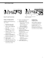
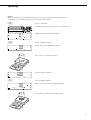
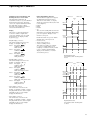
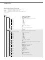
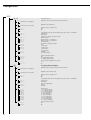
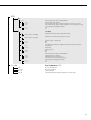
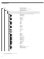
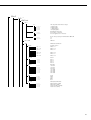
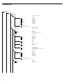
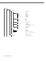
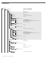
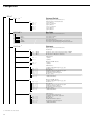
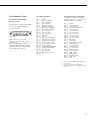
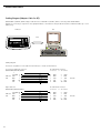
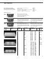
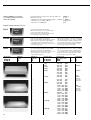
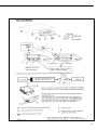
Cabling Diagram (Adapter Cable for PC)
(Model CW1P | CW1NP | CW2P: adapter cable 7357312; model CW1S | CW1NS | CW2S: connecting cable YCC02-D9F6).
Diagram for connecting a computer or other peripheral device to the indicator using the RS-232-C/V24 standard and cables up to 15 m
(50 ft.) long:
Indicator
PC
V24
Cabling diagram
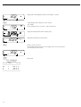
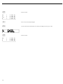
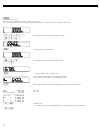
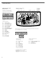
Connection assignments for the cable from the indicator to an RS-232 PC interface
82
25-contact D-Sub male connector
(Model CW1P/CW1NP/CW2P)
1
Sgn GND 7
Indicator T+D
2
side
R+D
3
DTR
20
CTS
5
D-Sub female connector:
9-contact or 25-contact
Open cable end
(Model CW1S/CW1NS/CW2S)
D-Sub female connector:
9-contact or 25-contact
Sgn GND 10
Indicator T+D
7
side
R+D
8
DTR
9
CTS
6
5
2
3
8
4
5
2
3
8
4
GND
R+D
T+D
CTS
DTR
GND
R+D
T+D
CTS
DTR
7
3
2
5
20
7
3
2
5
20
GND
RxD
TxD
CTS
DTR
GND
RxD
TxD
CTS
DTR
PC side
PC side