1
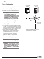
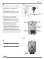
Atria™ Ceiling Fan Owner’s Manual
Congratulations on your purchase of a Casablanca ceiling fan!
Your new fan will be a beautiful addition to your home, keeping you comfortable throughout
the year. The true appreciation of a Casablanca ceiling fan is only complete when put
into actual use. Great time and care have been taken to construct and enhance what are
otherwise functional appliances. Beauty is found in the integrity, craftsmanship, and attention
to detail. Thank you for looking for the
nameplate that defines ceiling fans.
Contents
Parts Guide . . . . . . . . . . . . . . . . . . . . . . . . . . . . . . . . . . . . . . . . . . . . . . . . . . . . . 3
Product Specifications. . . . . . . . . . . . . . . . . . . . . . . . . . . . . . . . . . . . . . . . . . . . 5
Safety Considerations. . . . . . . . . . . . . . . . . . . . . . . . . . . . . . . . . . . . . . . . . . . . 6
Mounting Guidelines . . . . . . . . . . . . . . . . . . . . . . . . . . . . . . . . . . . . . . . . . . . . 7
Location . . . . . . . . . . . . . . . . . . . . . . . . . . . . . . . . . . . . . . . . . . . . . . . . . . . . . 7
Fan Size . . . . . . . . . . . . . . . . . . . . . . . . . . . . . . . . . . . . . . . . . . . . . . . . . . . . . 7
Structural Support . . . . . . . . . . . . . . . . . . . . . . . . . . . . . . . . . . . . . . . . . . . . 7
Sloped Ceiling Installations. . . . . . . . . . . . . . . . . . . . . . . . . . . . . . . . . . . . . 8
Installing the Mounting Hardware . . . . . . . . . . . . . . . . . . . . . . . . . . . . . . . . 9
Assembling . . . . . . . . . . . . . . . . . . . . . . . . . . . . . . . . . . . . . . . . . . . . . . . . . . 9
Attaching the Crossbar Mounting Bracket. . . . . . . . . . . . . . . . . . . . . . . . 9
Attaching the Canopy . . . . . . . . . . . . . . . . . . . . . . . . . . . . . . . . . . . . . . . . 10
Installing the Fan. . . . . . . . . . . . . . . . . . . . . . . . . . . . . . . . . . . . . . . . . . . . . . . 11
Assembling . . . . . . . . . . . . . . . . . . . . . . . . . . . . . . . . . . . . . . . . . . . . . . . . . 11
Hanging the Fan. . . . . . . . . . . . . . . . . . . . . . . . . . . . . . . . . . . . . . . . . . . . . 13
Connecting the Wires. . . . . . . . . . . . . . . . . . . . . . . . . . . . . . . . . . . . . . . . . 13
Installing the W-81 Wall Control . . . . . . . . . . . . . . . . . . . . . . . . . . . . . . . . . 14
Operating the W-81 Wall Control . . . . . . . . . . . . . . . . . . . . . . . . . . . . . . 16
Attaching the Canopy Hatch . . . . . . . . . . . . . . . . . . . . . . . . . . . . . . . . . . 16
Installing the Blades. . . . . . . . . . . . . . . . . . . . . . . . . . . . . . . . . . . . . . . . . . . . 17
Assembling . . . . . . . . . . . . . . . . . . . . . . . . . . . . . . . . . . . . . . . . . . . . . . . . . 17
Attaching. . . . . . . . . . . . . . . . . . . . . . . . . . . . . . . . . . . . . . . . . . . . . . . . . . . 18
Installing the Light Fixture. . . . . . . . . . . . . . . . . . . . . . . . . . . . . . . . . . . . . . 19
Attaching the Light Fixture. . . . . . . . . . . . . . . . . . . . . . . . . . . . . . . . . . . . 19
Installing the Halogen Bulbs. . . . . . . . . . . . . . . . . . . . . . . . . . . . . . . . . . . 20
Attaching the Glass Shade. . . . . . . . . . . . . . . . . . . . . . . . . . . . . . . . . . . . . 20
Troubleshooting Tips . . . . . . . . . . . . . . . . . . . . . . . . . . . . . . . . . . . . . . . . . . . 21
Problems and Possible Remedies. . . . . . . . . . . . . . . . . . . . . . . . . . . . . . . 21
Care Recommendations . . . . . . . . . . . . . . . . . . . . . . . . . . . . . . . . . . . . . . . . . 21
1
Atria
™
PLEASE INSPECT ALL PACKAGING PRIOR TO DISCARDING!
Your Casablanca fan was crafted with pride and care and inspected thoroughly prior
to shipment. Before you begin to assemble and install your fan, remove all parts
from the carton and check them against the Parts Guide in this manual.
Make sure all parts are included in the box
using the Parts Guide on the following pages.
• Always turn power to the ceiling fan OFF before
replacing lightbulbs or working on your fan.
If there are missing or broken parts:
• Never insert anything into the path of the
fan blades while the fan is in operation.
• Call 1-888-227-2178 Monday through Friday,
7 a.m. to 4 p.m. PST. Your request will be
handled immediately. Replacement parts
will be sent to you via Federal Express.
• Never install a fan over a pool or spa.
• Never operate a fan that has been
damaged in any way.
Proper Parts Handling
Install the fan according to the
instructions in this manual.
• Do not remove lightbulbs from their packaging
until you are ready to install them.
If the fan does not work:
• Before discarding packaging materials, be
certain that all parts have been removed.
• Use a clean, dry paintbrush to remove small
Styrofoam pieces that may remain after unpacking.
• Refer to the Troubleshooting Tips
in this Owner’s Manual
• Call Technical Support at 1-888-227-2178
• Do not brush Styrofoam into wiring cavities.
• Contact your local Authorized Service Center
• The blades in each pack are matched for
equal weight to assure smooth fan operation.
If more than one fan is being installed, do
not mix blades from different cartons.
Our Web site at www.casablancafanco.com contains
additional information on Casablanca products,
troubleshooting, and Authorized Dealer or Service
Centers. Please do not return this product to the store.
• When cleaning, painting, or working near your
fan, be cautious of the fan and blades.
RECORD MODEL AND SERIAL NUMBERS BEFORE INSTALLATION!
Please take a moment to locate the model number and serial number from your fan (see below) and record this
information on the Warranty page inside the front cover of this Owner’s Manual if it does not appear there already. These
numbers are found on the motor identification plate affixed to the fan motor in the following location as shown below:
Atria®
TYPE HANGER TYPE
POMONA, CA
DJ01 1151 MODEL #C18G500F
Motor Identification Plate
SERIAL No.: DJ06 2237
C18G500F
2
Serial Number
Model Number
Atria
™
Parts Guide
Item #
Description
Picture (not to scale)
Quantity
1.
Motor Housing
1
2.
Crossbar Mounting Bracket
1
3.
Phillips Screwdriver
1
4.
Lag Screw and Washer
1
5.
1" x 8-32 Round-Head Screws and Washers
2
6.
Canopy and Hatch
1
7.
2½" x 8-32 Canopy Screws and Lock Washers
5
8.
Adapter Cover
1
9.
4" Perma•Lock™ Downrod and Ball Assembly
1
10.
Allen Wrench
1
11.
Wire Nuts
8
12.
Light Fixture
1
13.
Light Fixture Screws
2
14.
C7 Incandescent Bulbs, 15W
8
15.
Blade Iron Support Ring
1
3
Atria
™
Item #
4
Description
Picture (not to scale)
Quantity
16.
Blade Iron Support Ring Screws
5
17.
Blade Irons
5
18.
Blade Iron Screws (NOTE: Five of the eleven are found on the
shipping blocks.)
11
19.
Blades
5
20.
Blade Iron Plate Screws
21
21.
Blade Iron Plates
5
22.
Balance Kit
1
23.
Halogen Downlight Bulbs, 50W
2
24.
Glass Shade
1
25.
Light Kit Cap and Finial
26.
W-81 Wall Control
1 set
1
Atria
™
Product Specifications
Model name:
Model number:
ETL Rating:
Dimensions:
Atria™
C18GXXXF
Damp
This device complies with Part 15 of the FCC rules.
Operation is subject to the following two conditions:
• This device may not cause harmful interference.
• This device must accept any interference
received, including interference that
may cause undesired operation.
A=
B=
C=
D=
E=
23.4"
28.8" NOTE: Dimension
3"
B includes light
17.1" fixture and glass.
5.6"
Weight:
Motor Type:
Motor Size:
Blade Span:
Blade Iron Pitch:
No. of Blades:
Technology:
Lightbulbs:
42 lbs.
XTR200™
30mm
68"
11˚
5
W-81 wall control
(8) 15-watt C7 incandescent
(2) 50-watt T4 halogen
Airflow:
9,042 cfm
Electricity Use*:
93 watts
Airflow Efficiency*: 97.4 cfm/watt
*Performance data is for fan only. No lighting
wattage is included.
This equipment has been tested and found to
comply with the limits for a class B digital device,
pursuant to Part 15 of the FCC rules. These limits are
designed to provide reasonable protection against
harmful interference in a residential installation. This
equipment generates, uses, and can radiate radio
frequency energy and, if not installed and used in
accordance with the instructions, may cause harmful
interference to radio communication. However, there
is no guarantee that the interference will not occur in
a particular installation. If this equipment does cause
harmful interference to radio or television reception,
which can be determined by turning the equipment
off and on, the user is encouraged to try to correct the
interference by one or more of the following measures:
• Reorient or relocate the receiving antenna.
• Increase the separation between
the equipment and receiver.
• Connect the equipment into an outlet on a circuit
different from that to which the receiver is connected.
• Consult the dealer or an experienced
radio/TV technician for help.
5
Atria
™
Safety Considerations
Safety and proper operation of your Casablanca fan both
require a thorough knowledge of the product and correct
installation; therefore, before attempting to install and
operate your fan, read this Owner’s Manual completely
and carefully. Retain this manual for future reference.
Fuse Box
(Remove fuse for the
circuit you will be
working on)
Circuit Breaker
(Trip breaker for the
circuit you will be
working on)
ÑÑCAUTION: RISK OF ELECTRICAL SHOCK!
18"
↑
70"
↑
Turn off all electricity at the circuit breaker
or fuse box before attempting any
installation procedure. Installation is to be
in accordance with the National Electrical
ANSI/NFPA 70-1999 and local codes. If
you are unfamiliar with the wiring codes,
contact a qualified electrician. To avoid
overheating and possible damage to
other equipment, do not install control
to a receptacle, fluorescent light fixture,
operating appliance, or transformersupplied appliance.
from bottom edge
84" ↑ of blade to floor
• This ceiling fan requires a grounded electrical supply of
120 VAC, 60 Hz and a minimum of 15-amp circuit. The
maximum current required for the fan with light fixture
if 2.9 amps. The fan uses about 1.1 amps (132 watts).
• Where wire nuts are employed, be sure all
bare wires are fully inserted into the metal wire
connectors inside the plastic wire nut covering.
• When installing the canopy, light kit, and wall
controls, make sure all wires are carefully
tucked away and that no wires are pinched.
• The fan must be supplied with three
independent 120V AC supply wires to provide
power for the fan, the light, and neutral.
ÑÑWARNING: Do not insert foreign objects
in between the rotating fan blades.
ÑÑWARNING: To reduce the risks of fire or
electric shock, do not use this fan with any
solid-state control device. Use only the
control provided with or recommended for
this fan.
6
Dimensions indicated are the minimum
allowable for proper installation.
Atria
Mounting Guidelines
Structural Support
Before mounting your Casablanca fan, read the
following helpful recommendations. Location,
fan size, and structural support are important
factors to consider before installation.
Installing a New Ceiling Fixture Outlet Box
Location
Ceiling fans have practical uses in almost every
room in your home. We suggest you follow
these mounting recommendations as you decide
where to install your Casablanca fan.
• For safety reasons, the fan blades must
be a minimum of 7' above the floor.
• Do not locate the fan in a doorway
or above a swinging door.
• In bedrooms, fans work best when
mounted above the foot of the bed.
• Over pool tables, be sure to provide plenty of
clearance to avoid damage from pool cues.
™
If you do not have an existing fixture located where
you wish to place your Casablanca fan, an approved
ceiling fixture outlet box must be installed and wired.
Using Existing Ceiling Fixture Outlet Box
After turning the power OFF at its source (either the circuit
breaker or fuse box), lower the old fixture and disconnect
the wiring. Check the ceiling fixture outlet box to be sure
it is marked “Approved for Ceiling Fan Mounting.” If it is
not, a new box must be installed. For new construction,
use an approved ceiling fixture outlet box with the rating
“50 lbs. or less”. Ensure that the outlet box is mounted to
a joist or stud beam. If not, a 2x4 stud must be installed.
ÑÑWARNING! To reduce the risk of fire,
electrical shock, or personal injury, mount
to outlet box marked “Acceptable Fan
Support of 22.7 kg (50 lbs.) or less” using
the mounting hardware provided with the
outlet box.
• In kitchens be sure to allow for open
cupboard doors to clear the fan blades.
• Do not install a fan close to or over a pool or spa.
High humidity combined with corrosive gases
will destroy the finish and warp the blades.
Fan Size
Variable fan speed capability permits the use of
a full-size fan even in smaller rooms. For very
large rooms, two fans may be needed.
When to Use a Lag Screw
A lag screw is required under two conditions: the fan
weighs 36 lbs. or more, or the existing ceiling fixture
outlet box needs to be modified for a ceiling fan
application (for example, you are replacing an existing
light fixture with a fan). We recommend that the ceiling
box be of sufficient capacity to support the weight
of the fan and light fixture under any conditions.
NOTE: The Atria weighs 42 lbs., so use of a
lag screw is required.
7
Atria
™
Sloped Ceiling Installations
Suggested Extension Downrod Lengths
Ceiling Height
Downrod Length
When to Use an Extension Downrod
9' 0"
standard
For optimum performance and appearance, use
an extension downrod with your Casablanca
fan when installing on high (cathedral) ceilings
or sloped ceilings. Casablanca offers accessory
downrods in increments of 6" up to 5’. See your
Authorized Casablanca Dealer for details.
9' 6"
standard
10' 0"
12"
Calculation of Ceiling Angle
Use the tear-off Ceiling Angle Template card inserted
in this manual. It provides you with a simple “go” or
“no go” for installing your fan on a sloped ceiling.
Extension
Downrod
Maximum angle
of Hang-Tru®
canopy = 32º
Blades must be a
minimum of 7 feet
above the floor
7' minimum
EXAMPLE 1
EXAMPLE 2
EXAMPLE 3
This slope is less than 32º.
It is OK to install your fan.
This slope is 32º. This is the
maximum slope that will allow the
fan to hang straight down. It is OK
to install your fan.
This slope is more than 32º. Your
fan will not hang straight down; an
adaptor is necessary. Contact your
local Authorized Casablanca Dealer in
regards to purchasing a Sloped Ceiling
Adapter.
NOTE: The fan may wobble or vibrate if the
downrod length is not long enough and the
inside blade is too close to the downslope or
side wall. Extending the downrod length will
usually solve this problem.
8
10' 6"
12"
11' 0"
18"
12' 0"
24"
13' 0"
36"
14' 0"
48"
15' 0"
60"
Atria
™
Installing the Mounting Hardware
Hardware (not to scale)
Crossbar Mounting
Bracket (1)
Lag Screw and Washer (1)
Canopy Hatch (1)
Canopy (1)
Assembling
1” x 8-32 Round-Head Screws
and Washers (2)
Phillips Screwdriver
2½” x 8-32 Canopy Screws and Lock Washers (3)
Steps 3-4
Joist
1
Prepare the ceiling fixture outlet box for the lag screw
by removing the plug in the center. If the outlet box does
not have a plug, drill a ½-inch hole in the center of the
box. After drilling a hole in the outlet box, drill a ¼-inch
hole 3 inches deep into the joist used to support the fan.
Ceiling wiring
Ceiling fixture
outlet box
(ceiling fan rated)
Attaching the Crossbar Mounting Bracket
2
To install the crossbar mounting bracket, route the
outlet box wires along side of the crossbar mounting
bracket. Attach the crossbar mounting bracket to the
outlet box with the set of two round-head screws and
washers. Use caution when installing the screws and
washers. Do not pinch the outlet box wires in the washers.
ÑÑCAUTION: To reduce the risk of personal
injury, use only the mounting hardware
provided with an approved outlet box (not
included) to install the crossbar mounting
bracket.
3
Pass the lag screw through the center hole in
the crossbar mounting bracket and the ceiling fixture
outlet box. Secure the lag screw into the guide hole in
the joist, tightening until the outlet box and mounting
bracket are mounted firmly to the support beam.
GREEN ground wire
Crossbar mounting
bracket
(ridge side down)
Washers (2)
1” x 8-32 RoundHead screws (2)
Lag screw and
washer (1)
9
Atria
™
Attaching the Canopy
Step 5
4
To install the canopy hardware, set aside the canopy
hatch and one canopy hatch screw and lock washer. You
will install the canopy hatch in the next section. Attach the
canopy to the crossbar mounting bracket with three of the
canopy screws and lock washers. Using the screwdriver
provided, tighten each screw until the canopy hardware
is mounted firmly to the crossbar mounting bracket.
Canopy
NOTE: On a sloped ceiling, align the canopy
opening with the top or peak of the room.
Lock washers (3)
Canopy hatch
Canopy screws (3)
10
NO DRILL
Atria
™
Installing the Fan
Hardware (not to scale)
Perma•Lock™ Downrod and
Ball Assembly (1)
Allen Wrench (1)
Wire Nuts (4)
Canopy Hatch (1)
Adapter Cover (1)
C7 Incandescent Bulbs, 15W (8)
Assembling
1
2
2½" x 8-32 Canopy Screws and
Lock Washers (1)
Step 1
Paper motor
shield
Remove the paper shield from the motor.
Examine the interior of the motor coupling. If the
end of the set screw extends inside the motor coupling
space, use the Allen wrench to loosen the screw.
Step 2
Set screw - CORRECT PLACEMENT
Allen wrench
Set screw - INCORRECT PLACEMENT
Allen wrench
11
Atria
™
3
Slide adapter cover onto downrod, then route the
fan wires through the downrod and ball assembly.
sTEPS 3-4
Downrod and ball
assembly
Motor wires
4
Insert the downrod into the motor coupling
and turn clockwise. When the downrod is securely in
place, re-tighten the set screw with the Allen wrench
until it will not turn any further. Test the stability of
the downrod assembly by attempting to unscrew the
downrod from the motor coupling. If the downrod turns
in either direction, the set screw should be tightened.
Adapter cover
Set screw
Tapered thread
Allen wrench
ÑÑCAUTION: The downrod has a tapered
thread designed to lock completely when
correctly installed. Failure to fully lock in
the downrod before securely tightening
the set screw may cause the fan to
separate from the downrod and fall
during normal operation.
5
Motor coupling
Step 5
Lower the adapter cover over the motor coupling.
Adapter cover
6
12
Screw in the eight lightbulbs.
Step 6
Atria
Hanging the Fan
7
Hold the motor housing with both hands. Insert
the ball of the downrod into the canopy opening.
Check to ensure that the wires are not pinched. Rotate
the motor housing until the slot in the downrod ball
locks into the pin opposite the canopy opening.
™
Step 7
Ball
Connecting the Wires
Slot
Pin
8
Trim the extra length from the motor wires. Be
certain to leave at least 6 inches of wire above the
downrod. Use a wire stripper (not included) to strip
½-inch of insulation from the end of each trimmed wire.
9
To attach the fan wires to the ceiling fixture
wiring, match the wire colors as described below,
hold the bare ends of the wires side by side, and
fully insert the wires into the wire nut. Secure by
rotating the wire nut in a clockwise motion.
Steps 8-9
RED and
BLUE wires
Connect wires in the following order:
• GREEN wires from mounting plate and downrod
assembly of fan to GROUND wire of power source.
• WHITE fan wire to WHITE neutral
wire from ceiling outlet box.
2 BLACK wires
2 WHITE wires
3 GREEN wires
• BLACK power wire from fan to BLACK
power wire in ceiling outlet box.
• BLUE D1 optional fan wire to RED power wire
(second hot wire) in ceiling outlet box.
Wire nut
NOTE: If the colors of your wiring differ from
that described, consult an electrician.
Inspect each wire nut to ensure that no bare wire is visible.
Test the connection by gently pulling on the wires. The wire
nuts should stay firmly in place, covering the bare ends.
13
Atria
™
Installing the W-81 Wall Control
Hardware (not to scale)
W-81 Wall Control
(assembled)
Wall Plate (2 colors included)
Wall Plate
Screws (4)
Switch Box
Screws (2)
The W-81 wall control must be supplied with three
independent 120V AC supply wires for proper operation
of the fan and lights. This control turns the fan and lights
ON and OFF, and adjusts the intensity of the lights.
ÑÑCAUTION: Ensure power is turned
OFF at the breaker or fuse panel before
beginning wall control installation.
NOTE: The W-81 wall control is designed to
replace a standard wall switch and fits wall
boxes (metal or plastic) with a depth of more
than 2".
1
Remove the screws and switch plate from the
existing wall switch box, and pull the switch away
from the box to expose the wire connections.
2
Disconnect the three wires from the existing
switch and remove the switch from the wall box.
The ends of the wires in the wall box may need to
be stripped before installing the new control.
NOTE: The wire nuts provided are only
suitable for use with copper wire. Use wire
nuts to join one 14-gauge wire with one 16- or
18-gauge wire.
14
Wall Control (1)
Wire Nuts (4)
Atria
3
To attach the wires in the wall box to the W-81
wall control wires, match the wire colors as described
below, hold the bare ends of the wires side by side,
and fully insert the wires into the wire nut. Secure
by rotating the wire nut in a clockwise motion.
™
Step 3
Connect wires in the following order:
• GREEN GROUND conductor from the wall box to
the GREEN wire from wall control (labeled GRD)
• BLACK wire from fan in the wall box to
YELLOW wire on wall control (labeled FAN)
• RED wire from fan in the wall box to RED
wire on the wall control (labeled LIGHT)
Note: BLUE D1 optional fan wire can be
connected to RED power wire in ceiling outlet
box.
• BLACK wire from the source of power
(HOT WIRE) wire in the wall box to BLACK
wire on wall control (labeled LIVE)
BLACK wire
(LIVE)
W-81 wall
control
(back view)
NOTE: If the colors of your wiring differ from
that described, consult an electrician.
Inspect each wire nut to ensure that no bare wire is visible.
Test the connection by gently pulling on the wires. The wire
nuts should stay firmly in place, covering the bare ends.
YELLOW wire
(FAN)
GREEN wire
(GRD)
RED wire
(LIGHT)
Step 4
4
Fasten the W-81 wall control into the
wall box with the two switch box screws.
ÑÑCAUTION: Be certain that the wires are
not pinched!
Switch box
screws (2)
15
Atria
™
5
Fasten one of the two wall plates (white or ivory)
to the wall control using the two wall plate screws.
Step 5
6
Set the fan pull-chain speed to HIGH and
the wall control fan speed knob to HI. Return
power to the panel and test the controller.
ÑÑCAUTION: Failure to set the fan pull-
Wall plate
screws (2)
chain speed to HIGH can result in faulty
operation of the fan and damage to the
wall control.
Operating the W-81 Wall Control
• Turn the upper knob to the desired fan speed.
• Turn the lower knob to the desired light setting.
Attaching the Canopy Hatch
7
Tuck the wires into the canopy with the wire
nuts pointed toward the ceiling. Place the BLACK and
WHITE wires on opposite sides of the canopy. All wires
should be clear of the canopy opening. Tilt the motor
housing and downrod to install the canopy hatch.
8
sTEPs 7-8
Canopy hatch
Canopy screw
and washer
Use the last remaining canopy screw and
lock washer to secure the canopy hatch. Straighten
the fan and ensure all parts are tightly secured.
Check for movement at the following joints:
• Between the canopy and the ceiling
• Between the canopy and the
downrod and ball assembly
16
NO DRILL
Canopy
Atria
™
Installing the Blades
Hardware (not to scale)
Blade Iron Screws (11)
NOTE: Five of the eleven are
found on the shipping blocks.
Blade Iron Support Ring (1)
Blade Iron Support Ring
Screws (5)
Blade Irons (5)
Blades (5)
Blade Iron Plates (5)
Blade Iron Plate Screws (21)
Assembling
1
Unscrew and remove the shipping blocks. Set
aside the five blade iron screws. They are used in later
steps to install the blade assemblies to the fan.
Step 1
Shipping block
Blade iron support
ring screw
2
Step 2
Install the blade iron support ring with
the blade iron support ring screws.
Blade iron
support ring
Blade iron support
ring screw
17
Atria
™
3
Assemble the blade irons, blades, and blade
iron plates. Place the blade iron on top of the blade
and the blade iron plate underneath the blade. Use
a manual screwdriver and the blade iron plate screws
to secure the blade assembly. Use four screws per
blade. Repeat this process for each fan blade.
Step 3
Fan blade assembly
Blade irons (5)
NO DRILL
ÑÑCAUTION: Do not use an electric
screwdriver to assemble fan blades!
Blades (5)
Blade iron plate screws (4)
Attaching
4
Install the assembled blades to the blade iron
support ring using 10 blade iron screws (use two screws
for each blade assembly). Align the screw holes on the
blade irons with the screw holes on the blade iron support
ring. Tighten the screws with a manual screwdriver.
Step 4
Blade iron
ÑÑCAUTION: Do not operate the fan at
this point. Installation must be completed
before turning on the fan.
Blade iron
support ring
Installed blade assemblies
18
Blade iron
screws (2)
Atria
™
Installing the Light Fixture
Hardware (not to scale)
Light Fixture (1)
Light Fixture Screws (2)
Halogen Downlight Bulbs, 50W (2)
Glass Shade (1)
Light Kit Cap and Finial (1 set)
Attaching the Light Fixture
1
Locate and remove the pre-installed wire nuts on
the motor housing wires.
2
To attach the light fixture wires to the motor
housing wires, match the wire colors as described
below, hold the bare ends of the wires side by side,
and fully insert the wires into the wire nut. Secure
by rotating the wire nut in a clockwise motion.
Steps 1-2
WHITE wire
from fan
BLUE wire
from fan
WHITE wire
from light
fixture
BLUE wire
from light
fixture
Connect wires in the following order:
• WHITE wire from the fan to the WHITE
wire from the light fixture
• BLUE wire from the fan to the BLUE
wire from the light fixture
Step 3
Inspect each wire nut to ensure that no bare wire is visible.
Test the connection by gently pulling on the wires. The wire
nuts should stay firmly in place, covering the bare ends.
3
Carefully coil or tuck the wires so they are not
pinched. Locate the four mounting holes in the light
fixture and align the four holes of the light fixture to
motor housing with the two screws pre-installed on the
motor housing. Then rotate the light fixture clockwise,
locking it to the bottom of the fan. Once the light
fixture has been mounted to the bottom of the fan as
shown in Step 3, install the remaining two screws, then
tighten all four screws with the provided screwdriver.
Light fixture screws (2)
19
Atria
™
Installing the Halogen Bulbs
Step 4
NOTE: Do not remove the protective sleeve on
the halogen bulbs. Touching the glass casing of
a bulb may damage or break the glass.
4
Cut the plastic sleeve on the halogen bulb to
expose the connection end of the bulb. Continue to hold
the bulb by the sleeve during installation. Install both
halogen bulbs into the light fixture. Please throw away
the plastic sleeve after installing the halogen bulbs.
ÑÑCAUTION: Only use maximum 50-watt
Halogen bulbs
halogen bulbs!
Attaching the Glass Shade
Step 5
5
Insert the threaded rod from the light fixture
through the hole in the center of the glass shade.
6
Step 6
Thread all pieces of the finial onto the threaded
rod. Screw the finial into place securely.
Installed fan
and light
fixture
20
Atria
Troubleshooting Tips
Care Recommendations
Please refer to this troubleshooting guide before
requesting service or contacting your dealer for assistance.
Fan Finishes
Problems and Possible Remedies
• Surface smudges or an accumulation of dirt
and dust can be removed easily using a mild
detergent and slightly dampened soft cloth. An
antistatic agent may be used (on the fan base
and blades only), but never use abrasive cleaning
agents as these will damage the finish.
Fan will not start
• Check the main circuit fuses, circuit breakers, and wall
control position. Check all wire connections. Make
sure the power is turned off during this inspection.
™
• For cleaning, use a soft brush or lint-free
cloth to prevent scratching the finish.
Blades
Fan wobbles or shakes excessively
• Be sure the canopy pin is set properly
into the slot on the ball.
• The hanger bracket may be attached too loosely.
Make sure the hanger bracket is attached tightly to the
ceiling and the downrod assembly is secured firmly.
• Wood-finish blades should be cleaned with
a furniture polishing cloth. Occasionally, a
light coat of furniture polish may be applied
for added protection and beauty.
• The downrod may be attached to the
downrod base too loosely. Make sure all
the screws are securely tightened.
• For painted and high-gloss blades, surface
smudges or an accumulation of dirt and dust can
be removed easily using a mild detergent and
slightly dampened soft cloth. An antistatic agent
may be used, but never use abrasive cleaning
agents as these will damage the finish.
Fan is noisy during operation
No Need for Lubrication
• Tighten the canopy screws and mounting plate
assembly. Make sure the wire nuts inside the
canopy and switch housing are not touching
the metal parts and that they have not fallen
off the wire splices. Tighten as necessary.
• Never lubricate this fan! The precision motor
at the heart of your Casablanca fan features
sealed bearings that are lubricated for life.
• Tighten the screws attaching the blade
assemblies to the motor housing and all of
the screws in the blade assemblies.
Changing Lightbulbs
• Make sure all screws are snug but not overly tight.
Fan does not run on low speed
• Do not attempt to oil the motor.
• Be sure to turn the power to OFF at the wall control
or circuit breaker before changing lightbulbs.
• Replace bulbs with the same type as you
removed from the light fixture.
• If the fan is new, it may need to be “broken
in.” Run at high speed for several days.
21
Atria
22
™