1
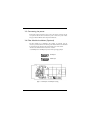
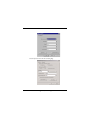
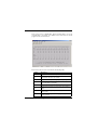
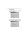
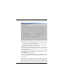
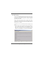
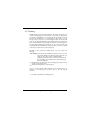
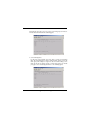
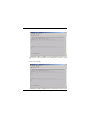
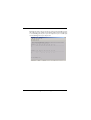
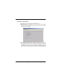
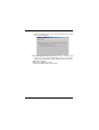
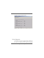
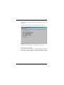
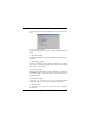
Easy/Smart 24-port
10/100 Base-TX Ethernet Switch
User’s Guide
SE0224/SS0224
FCC Warning
This equipment has been tested and found to comply with the limits for a
Class B digital device, pursuant to Part 15 of the FCC rules. These limits are
designed to provide reasonable protection against harmful interference when
the equipment is operated in a residential environment. This equipment
generates, uses, and can radiate radio frequency energy and, if not installed
and used in accordance with this user's guide, may cause harmful interference
to radio communications. However, there is no guarantee that interference
will not occur in a particular installation.
CE Mark Warning
This is a Class B product. In a domestic environment, this product may cause
radio interference, in which case the user may be required to take adequate
measures.
Trademarks
Copyright ©2001 Benq Corporation.
Contents subject to change without prior notice. Benq is a registered
trademark of Benq Corporation. All other trademarks belong to their
respective proprietors.
Copyright Statement
No part of this publication may be reproduced in any form or by any means or
used to make any derivative such as translation, transformation, or adaptation
without permission from Benq Corporation.
1. Introduction ............................................... 1
1.1. Product Overview .......................................................... 1
1.2. Features & Specifications ............................................... 2
1.2.1. Features ........................................................................................ 2
1.2.2. Technical Specifications ............................................................. 3
1.2.3. Physical Specifications ................................................................ 3
1.3. Product outlook and LED Display .............................. 4
1.3.1. Product outlook .......................................................................... 4
1.3.2. LED Display.................................................................................. 1.4. Package contents ............................................................. 5
2. Installation ................................................. 6
2.1. Operating Environment ................................................. 6
2.2. Connecting to network devices .................................. 6
2.3. Connecting the power ................................................... 7
2.4. Fiber Module Installation (Optional) .......................... 7
3. Configuration (SS0224 only) .................... 9
3.1. Setting up Console Port Connection ......................... 9
3.2. Instructions in navigating the console program ......12
3.3. Basic port-based configuration ................................... 14
3.3.1 Port enable/disable [E] ............................................................... 14
3.3.2 Auto-negotiation [A] ................................................................. 14
3.3.3 Port data rate [R] ....................................................................... 15
3.3.4 Duplex mode [D] ....................................................................... 16
3.3.5 Flow control [F] .......................................................................... 16
3.4. Port mirroring setting ................................................... 17
3.5. VLAN settings ................................................................. 21
3.6. QOS settings ................................................................... 23
3.7. Trunking ........................................................................... 27
3.8. System Information ........................................................ 32
3.9. Save Configuration ......................................................... 34
4. Trouble Shooting .....................................36
Appendix: ...................................................... 37
Ordering Information: .......................................................... 37
1. Introduction
1.1. Product Overview
This user’s manual describes and illustrates the installation method and usage
of the 24-port Fast Ethernet Switch. The rack-mount switch (SS0224/
SE0224) introduced here provides twenty-four 10/100Mbps Fast Ethernet
ports to segment traffic, extend Fast Ethernet connection distance, and
convert data packets between different transmission speeds. This Fast
Ethernet Switch provides shielded RJ-45 ports both with 10Base-T and
100Base-TX Auto-negotiation capability and MDI/MDI-X auto crossover. All
ports in this switch support Full-Duplex and Half-Duplex operation modes.
Addressing the demand for fiber, the switch (SS0224/SE0224) provides two
optional multi-mode or single-mode fiber module supporting SC, ST, MT-RJ,
or VF-45 connector. Hence, the switch can provide maximum 26 ports
simultaneously, i.e. 24 10/100Base-T/TX ports plus two 100Base-FX fast
fiber ports.
Furthermore, this powerful Fast Ethernet Switch utilizes stored-and-forward
switching architecture that filters and forwards data after the complete data
packet is received and examined to be free of errors. With one set of status
LEDs for each individual port, the switch operation status can be easily
monitored. The switch is rack-mount design that can be mounted on the
industrial standard 19 inches rack in the enterprise wiring center.
For SS0224 only, the switch offers advanced software configurable features,
including individual port setting, port-based Virtual Local Area Networking
(VLAN), port-based trunking, 802.1p based QoS, and port mirroring.
1.2. Features & Specifications
• Compliant with IEEE 802.3 10Base-T Ethernet and 802.3u 100Base-TX Fast
Ethernet Standards.
• Provides 24 ports for 10Base-T/100Base-Tx, standard RJ-45 connectors.
• All RJ-45 ports supports 10Base-T/100Base-Tx and Full-Duplex/HalfDuplex Auto-negotiation function.
• Supports MDI/MDI-X auto crossover.
• Optional up to 2 ports fiber module for 100BASE-FX multi-mode module
with ST, SC, MT-RJ, or VF-45 connector, or 100BASE-FX single-mode
module with SC connector.
• Supports store-and-forward switching mechanism.
• Supports port-based VLAN (SS0224 only).
• Supports port-based trunking (SS0224 only).
• Supports 802.1p based QoS (SS0224 only).
• Supports port-mirroring (SS0224 only).
• Supports Plug-and-Play.
• Supports up to 4K MAC addresses table / hashing algorithm on address
learning.
• Supports Aging function and 802.3x flow control for full Duplex and
collision-based backpressure function for half duplex operation.
• 768k Bytes buffer memory.
• Automatic address learning, address aging and address migration.
• Simple and economical way to bridge 10Base-T network and 100Base-Tx
network.
• Easily connect and segment Fast Ethernet hubs or segments.
• Front panel diagnostic LEDs.
• Rack-mount design that can be mounted on the industrial standard 19
inches rack in the enterprise wiring center.
• Ethernet Standards
• Protocol
• 10/100Mbps Ports
• Module ports
IEEE 802.3 10Base-T, 802.3u 100Base-TX
CSMA/CD
RJ-45 x 24
Optional up to 2 slots for 100Base-FX multimode or single-mode fiber module optic
fiber
• MAC address
• Buffer Memory
• VLAN
• Trunking
4k
768K Bytes
Port-based up to 24 groups (SS0224 Only)
Port-based up to 12 groups (SS0224 Only)
per unit: Power Status (1 LED);
• LED report
per port: 10/100M; LNK/ACT; FDX/COL (3
LEDs);
• Transmission Method
• Forwarding Rate
per module: LNK/ACT, FDX/COL (2 LEDs).
Store-and-forward
14,880pps for 10Mbps; 148,800pps for
100Mbps
• Power
• Operating Temperature
• Storage Temperature
• Operating Humidity
• Storage Humidity
• Emission Compliance
• Safety
• Dimension
90VAC~240VAC 47Hz~60Hz
0°C ~ 50°C
-20°C ~ 70°C
10% ~ 90% RH
5% ~ 90% RH
FCC part 15 Class A, CE Mark, VCCI, C-tick
UL/CSA
W 435 mm x D 221 mm x H 44mm
(17.1” x 8.7” x 1.8”). Standard 19” rackmountable size, one-unit-height.
• Net Weight
2.9kg (6.41b)
1.3. Product outlook and LED Display
Front View
SS0224 Front Panel:
SE0224 Front Panel:
Rear View
SS0224 Rear Panel:
SE0224 Rear Panel:
'#%
(
'+-.
(
'#%
(
!"#
$
#%&
&
)
(*)+
)
(
%"#
$
,
( #%
.
###/
'+
'0,0+
.##
.
%#,#/
1.4. Package contents
Packing List
!
"
#$%&%'%(
) *+
,.**,*
[!] IF any item is found missing or damaged, please contact your local Benq
reseller for replacement.
2. Installation
2.1. Operating Environment
This switch must be installed and operated within the limits of specified
operating temperature and humidity (see previous section under
Specifications).
• Do not place objects on top of the unit.
• Do not obstruct any vents at the sides of the unit.
• Do not position the unit near any heating source such as heater, radiator,
or direct exposure to sun.
• Prevent entering of water and moisture into the unit.
• If necessary, use dehumidifier to reduce humidity.
• Always avoid dust and dirt.
• Allow some space between the product and the surroundings to facilitate
dissipation of heat generated inside the switch.
2.2. Connecting to network devices
The RJ-45 ports on the switch are designed as MDI/MDI-X auto crossover
ports which allow using straight-through cables to connect any port on this
switch to network device.
Connect one end of the network cable to the RJ-45 port on the front panel,
and connect the other end of the network cable to the RJ-45 port on the
network device. Follow the same procedure to connect all the RJ-45 ports of
the switch. The UTP network cables must comply with EIA/TIA 568
specifications and Category 5 standard for 100Mbps data transmission and
Category 3, 4, 5 for 10Mbps connection. Maximum length, using UTP cable,
between the switch and connected device is 100 meters (328ft). Once the
network cable is connected to both ends and the attached network device is
powered on, the green LINK/ACT LED for corresponding port should be lit
and the other two diagnostic LEDs shall reveal the port is under what kind of
connection status, e.g. full/half duplex, 10/100M speed.
%**
/
2.3. Connecting the power
Connect the output end of the power cord to the power connector on the
rear panel of the unit. Then connect the power cord to the power outlet.
The green Power LED on the front panel should be lit.
2.4. Fiber Module Installation (Optional)
The fiber module is not included in the package, it’s optional. You can
choose to purchase the fiber module for your switch. The fiber module shall
be inserted into the expansion slot located at the rear of the switch.
• Remove the module from the static free container
• Set Full Duplex or Half Duplex operation mode by using J2 jumper
Full Duplex
Half Duplex
Figure 1. Full Duplex or Half Duplex setting
%**
0
• Unscrew the cover plate of the expansion slot.
• Remove the plate and keep it for future use when you decide to remove
the module
• With the power off, slide the module into the slot
• Once it is slid in fully, snap in the module to make a proper connection and
fasten the screws
• Then connect the module to the fiber optical cable
• Turn on the power
Once the power is on, the yellow F1(or F2) card exist LED on the front
panel should be lit. Besides, once the fiber is appropriately connected
between fiber module and other network device, the link status shall be seen
by the lit state of the green LED: LINK/ACT for 100FX port.
Figure 2. Fiber module being installed
%**
1
3. Configuration (SS0224 only)
This section explains the configuration of smart switch, SS0224. For each 10/
100Base- T/TX port, basic setting include port speed, duplex mode, flow
control, auto-negotiation, etc. Other enhanced features configuration
include port-based VLAN, port-based trunking, QoS, and port mirroring.
3.1. Setting up Console Port Connection
To configure your switch through the console port, it is necessary to first set
up a terminal emulation program, and the HyperTerminal for Windows
95,98,and NT is suggested. Before setting the Hyper Terminal, make sure
that the switch, RS-232 cable and the PC are in proper installation. Then
connect PC to the console port in the back of SS0224 using a RS-232 straight
cable.
To configure the Hyper Terminal utility, please go with the following steps:
• Running the Hyper Terminal utility program.
• Select COM port to communicate with SS0224.
• Set the serial port properties then Press OK.
%
4
2%
#5*,!
4
,!
6#
+ 7-
55*
1**%8%
!8
!*,
**
3/!%+
*
2*
-
" 9*"* 5!%%
2*
+
,-3
Select Properties menu and choose Setting Page.
2*
+
,-
Check ASCII Setup menu and set.
2*
+
,-
Turn on the power of SS0224 after Hyper Terminal utility is set. If the
communication is successful, user should see the main menu of console
program on the screen as below:
Parameters in this screen are described in the following table.
Field
Description
Port
Displays the number of the currently selected port.
LINK
Displays the current link status between the selected port and the
connected node. This can be Up or Down.
En
Displays the selected port’s enable[ON] or disable[OFF] status
An
Displays auto negotiation function status of the selected port. This
can be enable[ON] or disable[OFF].
Rate
Displays user set port speed. This can be 10 or 100Mbps.
Duplex
Displays duplex mode of the selected port. This can be [FULL] or
[HALF]
Flow
Displays flow control capability of the selected port. This can be
[ON] or [OFF]
Mirror
Displays Port mirroring status, mirroring [ON] or [OFF], or set as
capture port[CAP]
2*
+
,-
Under this main menu of the console program, user can monitor 12 RJ-45
ports' brief status at the same page, i.e. port 1~port 12. Press [Enter] to
toggle to monitor the other 12 ports, i.e. port 13~port 24. See the following
figure:
3.2. Instructions in navigating the console program
To navigating the console program, user can follow the instructions in the
table below:
To do this…
Instructions…
Move to the submenus
Press the first character of each option line
Select a specific port
Press Corresponding: 1 2 3 4 5 6 7 8 9 10 11 12 13
14 15 16 17 18 19 20 21 22 23 24 25(F1) 26(F2)
Go back to the upper menu
Press ESC key
2*
+
,-
!
&!
!
!!"#$
%
%
%
%
''(
!
'(
)$
*+
'
%$$(+!
#
,
,-"
#
.
.
.
.+&
.,
'.'
.
.
Console
Program
Screen
For example, the following steps will disable or enable Auto-negotiation
function for port 2.
1. Press A to access the set auto-negotiation control screen.
2. Press 2 and Press 'Enter' to access flow control screen of port 2.
3. Press D to disable auto-negotiation function or press E to enable it.
2*
+
,-
3.3. Basic port-based configuration
The basic configurations provided here only apply to 24 RJ-45 ports. They
includes the following feature:
!
In this feature, user can disable/enable selected port. And the default setting
is port enabled. To enter this feature, press [E] from the main menu. For
example: Select port 1 and press 'D' to disable port 1's transmit and
receiving. On the contrary, user can enable it following the same policy.
Refer to below figure.
"#$ "!
In this feature, user can enable or disable the auto-negotiation function of
each RJ-45 port. The default setting is auto-negotiation enable. To enter this
feature, press [A] from the main menu. For example, to disable port 2's
2*
+
,-
auto-negotiation function, refer to the following steps: select port 2 and
press [D] to disable. See the figure below.
%!
This feature is only used when the port's auto-negotiation function is
disabled. User can force to change specific port's data rate to 10Mbps or
100Mbps.Press [R] from the main menu to enter this setting. For example:
force port 3's data rate to 10Mb, refer to the figure below. User should note
that to force specific port's rate, auto-negotiation feature will be disabled at
the same time.
2*
+
,-/
&'( !
Like the case in data rate setting, duplex mode setting is only changed when
the corresponding port's auto-negotiation function is disabled. Press [D]
from the main menu to enter this setting. For example: to set port 4 to half
duplex mode, refer to the following figure.
)*
!
User can set flow control capability for each RJ-45 port. Press [F] from the
main menu to enter this setting. The default setting for flow control
capability is enabled. For example: to disable port8's flow control capability,
refer to the following figure.
2*
+
,-0
3.4. Port mirroring setting
SS0224 support port mirroring function, which allows any port's ingress and/
or egress traffic to be mirrored to a pre-defined capture port. Several
flexible rules can be applied to mirroring: First, for each mirror port, user
can choose to mirror ingress or egress traffic or both. Second, for all the
ingress mirrored packet streams, user can choose to mirror packets whose
SA (source address) or DA (destination address) field is matched by a predefined MAC address. Then, to prevent possible congestion in the capture
port, user can set a divider value n, ranges from 0x0001(1) to 0x03FF(1023).
And the traffic stream will be mirrored 1 packet for each n packet. All the
rules above can be set independently for both ingress and egress traffic.
NOTE:
1. Only one port can be chosen as capture port at the same time.
2. Mirror multi-ports is possible but can create congestion at the mirror
capture port.
For detail procedures in setting port mirroring function:
P: set port mirror status to be the capture port or mirror ingress, egress or
both ingress and egress frames on the selected port.
C: set to Capture port
B: mirror both Ingress and Egress frames of the selected port
O: set to OFF
I : only mirror ingress frames
E: only mirror egress frames
2*
+
,-1
For examples: Set port 1 as capture port and mirror both ingress and egress
frames of port 2. Refer to the following two figures:
2*
+
,-3
After choosing to mirror both ingress and egress traffic of port 2,
I/E: Ingress/Egress mirror rule Configure, use this function to select mirror
rules of all system. After press [I] or [E] to enter ingress/egress mirror
rule configure, user can see the following items:
• Press “P” to monitor all frames of all ports that are set as Ingress/Egress
ports.(default will mirror all frames of selected ports)
• Select “D” to mirror all Ingress/Egress frames that has specific Destination
MAC Address(Setup in 'M' enter MAC Address) of all ports that be chosen
set as Ingress/Egress ports.
• Select “S” to mirror all Ingress/Egress frames that has specific Source MAC
Address(Setup in 'M' enter MAC Address) of all ports that be chosen as
Ingress/Egress ports.
• Press “M” to setup the MAC Address.
• Press “V” to set Ingress/Egress mirror divider. The value indicates receive/
transmit frames that have passed the device and divided by the value only
one in n frames.
For example, to set ingress mirror rules as " For those mirror ingress ports'
traffic, only mirror those whose SA is 01-02-03-04-05-06. And the mirroring
frequency is to mirror 1 packet for every 100 packets", user should can
follow the below steps: 1. Press [I] to enter ingress rule configure. 2. Press
2*
+
,-
[S] to select source address as matched target. 3. Press [M] and enter MAC
address "010203040506" 4. Press [V] to enter divider value "0x0064". Refer
to the following figure:
R: Reset all mirror Configure. User can use this function to disable all mirror
configuration.
2*
+
,-
3.5. VLAN settings
Virtual Local Area Networking (VLAN) enables efficient traffic separation,
provides better bandwidth utilization, and alleviates scaling issues by logically
segmenting the physical LAN so that packets are switched only between
ports within the same VLAN.
This also creates secure segments within the existing network. Nodes
residing in different VLAN segments cannot communicate with each other
although they are connected to the same switch. The resulting security is yet
another reason to use VLANs.
In this feature, user can set up VLAN related features following the steps
below:
1. Each time when user enters this submenu, system will ask whether to
reset the original VLAN configuration. The setting after switch power
ON is either the last time setting read from the EEPROM or factory
default, that is, all 24 RJ-45 ports and 2 optional FX ports (F1,F2) all
belong to one same VLAN group, i.e. V01. Refer to the following figure.
2*
+
,-
Select (Y)es to reset VLAN group. At this time, no ports belong to any
VLAN groups and therefore user should note that traffic between ports is
disabled. In a word, the switch is disabled. After making decision about reset
VLAN, user can set the VLAN groups or toggle between VLAN pages, i.e.
page1~4, to check all 24 VLAN groups' status. For example, user chooses to
see VLAN page3 after reset VLAN groups; refer to the following figure.
2. Select Vlan page number to see each VLAN groups' members. In each
page, 6 VLAN groups' members are shown. For example, in the figure
below it shows that port 1, 2, 5, 6 are the only members of VLAN group
V08, and port 14, 15, F1, F2 are members of VLAN group V12.
3. Press[S] to set VLAN group. Select Group then choose port to join or
leave the VLAN group. For example, if port 1 wants to leave VLAN
group3, only select VLAN group3 and then choose port 1 to leave. As
that port 1 will leave V03 and the updated VLAN group status will be
shown on the screen.
4. To move back to the main menu, press [ESC] to exit the VLAN submenu.
2*
+
,-
3.6 QoS settings
SS0224 can support port-based QoS, 802.1p compliant QoS frame. Basically,
SS0224 will classify the traffic with two levels of priority, i.e. "high" or "low"
priority. High priority packet streams experience less delay inside the switch,
which supports certain delay-sensitive traffic, such as real-time video or VoIP
streams.
In this feature, user can perform the following features:
• E/D: enable / disable port base qos setting. Set Enable will open all QOS
Functions. It means the device will have such ability to receiving
802.1p frames and accept the Configure under below setting.
• W: Setting the high/low priority queue weighting.
• T: Setting TCI THRESHOLD of 802.1p frame. If 802.1p frame pri[2:0] >=
TCI THRESHOLD. Then it will be qualified as high priority frame.
• P: Port Based setting. Set high or low priority to decided ports. Default
setting for each port's ingress traffic will be classfied as "low" priority.
While ingress traffic from the "high" priority ports will be set as with
high priority.
User can set QoS related functions according the following steps:
1. Set High/Low queue weight.
User can set different queue weight for "high" and "low" priority traffic.
For example: set high queue to "0x0A" and low queue to "0x01". It means
the system will transmit 10 packets in high queue then transmit 1 packet in
low queue. Under QoS submenu, press [W] to enter; then press [H] to
set high queue:
2*
+
,-
Change weight value to "a"(10), then screen will be like below figure:
After press "SPACE" to return to QoS submenu, user can set the weight
value for low priority by the same policy.
2. TCI THRESHOLD.
Use can change the threshold for 802.1p frame. Allowable threshold value
range is 0~7. If 802.1p frame pri[2:0] >= TCI THRESHOLD then it will be
qualified as high priority frame. For example, to change TCI THRESHOLD
to 6, do the following steps: Press [T] to enter TCI THRESHOLD menu,
then enter 6 for TCI THRESHOLD value, refer to the figure below:
2*
+
,-
3. Port Based Qos.
In this item, user can set decided port as high or low priority port. To set
Port 1 as high priority port, do the following steps: Press [P] to enter this
item and press [P] to set port.
Then select port 1 to set it as high priority by press [H]. Refer to the
following figure:
2*
+
,-/
Then the user can see from the below figure that port 1 has already been set
as high priority:
After above steps, all packets received by port 1 will be treat as high priority
packets if QoS feature is enabled.
2*
+
,-0
3.7 Trunking
SS0224 provides port-based trunking function. The switch can support up to
12 different trunking groups. The members of each group can range from 2
to 8 and the only limitation is each trunk group can only include ports from
the same chip. In SS0224, port 1 ~ port 8 belongs to chip-0, port 9 ~ port 16
belongs to chip-1, and port 17 ~ port 24 belongs to chip-2. The 2-port trunk
group can provides bandwidth of up to 200Mbps, while 8-port trunk group
can provides bandwidth of even 800Mbps. Note that for every trunk group, a
corresponding forwarding table should be set up at the same time. The
forwarding table will tell SS0224 the traffic from other ports will be assigned
to which port member in the specific trunk group.
Generally, in this port-based trunking feature, user can perform the
following:
• Select Chip: select chip number. Available chip number is 0 to 2, and each
chip provides 8 RJ-45 ports. After selecting specific chip, user
can choose 'E' or 'D' to enable or disable trunking
configuration under this chip. It means the specific chip will
have such ability of port trunking after setting Trunk group
and Forwarding table.
• T: Setting trunk group. Each chip provides 4 trunk groups and there at least
two ports in one trunk group.
• F: Assign forwarding table for each trunk group.
User can set the trunking related functions by the following steps; for
example, to set trunk group 5 and choose port 11, port 15 as group
members:
1. Select Chip 0 and Enable the trunking function.
2*
+
,-1
Press [T] to enter trunking submenu and select chip 0. Choose enable
trunking to enter trunking group and members selection. Refer to the
following:
Each time when user enables certain chip's trunking function, further set-up
menu will show up; otherwise, the system keeps in stand-by status and waits
for user to select specific chip or to exit menu.
2. Select Trunk group 5 and choose port 11, 15 as trunking ports.
Press [T] to set trunk group and select port 11, then enable trunk group
to activate port 11 in Trunk group 5. Refer to the following figure:
2*
+
,-3
Following the same policy, user can set port 15 as Trunk group 5's members.
And the status should be like the following figure:
3. Set Forwarding Table.
For all ports except trunking ports, they have to assign one forwarding
table. The forwarding table is used to indicate which specific port in the
trunk group will actually be assigned to take the traffic loading to this
trunk. For the above example in chip 1's trunk setting menu, user should
press [F] to set its forwarding table. Refer to the following figures:
2*
+
,-
Choose port 1 and set its traffic to one of trunk group 5's member, e.g. port
11.
Refer to the following:
2*
+
,-
Following the same policy, we can choose other ports' forwarding port for
this trunk group. For example, the forwarding table below shows that port
11 is forwarding port for port 1~port 10 and port 12~ port 14, while port
15 is forwarding port for port 16~port 24.
2*
+
,-
3.8 System Information
In this submenu, user can perform the following features:
F: Display F/W version number, which is a view-only screen showing the
software version of the switch. Press [F] to show this version number.
Refer to the following figure:
A: Age Time, which will show current aging time and user can set new age
time to this system. Besides, user can choose to disable aging function and
the MAC address learned in the switch will no longer be aged. The
available aging time is in the range from 0x0001 to 0xFFFF (unit: second).
That is, from 1 to 65535 seconds. For example, when original aging time
2*
+
,-
is 4812 secs (0x12CC), and we try to change aging time to 500 seconds:
refer to the following figure:
B: the BIST (Burn-In Self Test) Status, which is a view-only screen
showing the internal self-test (RAM, Buffer Control, packet buffer
memory) during initialization/power-up. Available information includes:
• MIB RAM Test: Pass/Fail
• Buffer Control RAM Test: Pass/Fail
• Internal Packet Buffer Memory Test: Pass/Fail
2*
+
,-
Press [B] in this submenu, user will see the below:
3.9 Save Configuration
In this submenu, user can choose to save above features configuration by
item, or just save all configuration to EEPROM in SS0224. Hence, next time
when switch is power ON, the last time setting will be automatically
2*
+
,-
downloaded and used as default setting for all features unless user tries to
modify them.
Press [S] from the main-menu to enter the Save submenu as below:
SS0224 provides the following by-item configuration saving function:
“P”: Save Port control configure
This saving function will save basic port control functions, including port's
transmit/receive enable or disable, auto negotiation ON/OFF, rate, duplexmode, and flow control capability. For example: from the Save submenu,
2*
+
,-/
user can press [P] to enable saving configuration of port control settings. See
below:
“A”: Save Aging time configure
This will save configuration of aging time and aging enable/disable status of
SS0224.
“V”: Save VLAN configure
This will save VLAN related configuration, including all the VLAN groups and
its members.
“T”: Save Trunking configure
This will save Trunking related configuration, including all the Trunking
groups and its corresponding forwarding table. Besides, all chips' trunking
function status are also recorded.
“Q”: Save QoS configure
All the QoS configuration will be recorded, including 802.1p compliant TCI
THRESHOLD, high/low priority weighting values, and the priority of each
port's receiving packet streams. The status of whether QoS feature is
enabled is also saved.
“M”: Save Mirror configure
In this item, user can choose to save all the port-mirroring related
configuration: each port's mirror status, and all ingress and egress rules.
“S”: Save All configure
For convenience, user can choose to save all the above configuration
provided above.
2*
+
,-0
4. Trouble Shooting
The SS0224/SE0224 can be easily monitored by its LED indicators. Please
follow the troubleshooting steps below to solve any problem you may
encounter during installation or implementation of the SS0224/SE0224.
*
Check if the power cord is properly connected to the power outlet and
is firmly plugged into the power socket of the switch.
+(
,-
.*
/"+/
• Check the power switch of the network device attached to the switch;
make sure it is turned ON.
• Check the network cable; make sure it is properly connected to the
switch and the network device.
• Check the network cable; make sure the UTP cables comply with EIA/
TIA 568 and Category 5 specification.
• Please check whether the RJ-45 cable is functional. Replace with
another working cable and see whether the condition can be improved.
• Use another port on the SS0116/SE0116. If a link can be established this
way, the first port is faulty. Please contact your local acercm dealer for
assistant.
• Make sure that all devices are connected to the network.
• Please ensure that the network adapter cards installed in the
workstation or other devices to the switch are in well working
condition.
[!] Contact your dealer if problem persists.
#
$
21
Appendix:
Ordering Information:
Part Number
99.334N2.001
99.335N2.001
99.33228.001
99.33228.002
99.33228.003
99.33228.004
99.33228.005
99.33228.006
99.33228.007
Model Number
SE0224
SS0224
MFF001-SC
MFF001-ST
MFF001-VF45
MFF001-MTRJ
MFF001-SC20
MFF001-SC40
MFF001-SC60
Description
24-Port Fast Ethernet Switch
24-Port Smart Fast Ethernet Switch
100Base-FX Fiber Module, Multi Mode, SC connector
100Base-FX Fiber Module, Multi Mode, ST connector
100Base-FX Fiber Module, Multi Mode, VF-45 connector
100Base-FX Fiber Module, Multi Mode, MT-RJ connector
100Base-FX Fiber Module, Single Mode 20Km, SC connector
100Base-FX Fiber Module, Single Mode 40Km, SC connector
100Base-FX Fiber Module, Single Mode 60Km, SC connector
!!:3
Benq Corporation (“Benq”) warrants the Benq network product you have
purchased from Benq or from an Benq Authorized Reseller to be free
from defects in materials and workmanship under normal use during the
warranty period of one year from the date of purchase. Your original
purchase invoice (sales receipt), showing the date of purchase of the
network product, is your proof of the date of purchase. This warranty
extends only to you, the original Purchaser. It is not transferable to anyone
who subsequently purchases, leases or otherwise obtains the network
product from you.
During the warranty period, Benq will, at no additional charge, repair or
replace defective parts with serviceable used parts that are equivalent to
new parts in performance. All exchanged parts and network product
replaced under this warranty will become the property of Benq. There will
be no charge for labor or parts during the one-year warranty period from
the date of purchase.
To ensure timely response to a service request, please complete and
detach the Benq Warranty Registration Card, then return it
together with a copy of your sales receipt to Benq within ten (10)
calendar days after date of purchase by end user.
In the event the network product exhibits a defect in material or
workmanship within the warranty period, Benq will provide the warranty
services applicable to the network product as defined below.
The Limited Warranty does not extend to any network product not
purchased from Benq or from an Benq Authorized Reseller. This limited
warranty also does not extend to any network product that has been
damaged or rendered defective (a) as a result of use of the network product
other than for its normal intended use, failure to use the network product in
accordance with the User's Manual which accompanies the network product
or other misuse, abuse or negligence to the net
work product; (b) by the use of parts not manufactured or sold by Benq; (c)
by modification of the network product; (d) as a result of service by anyone
other than Benq or an Benq Authorized Service Provider; (e) improper
transportation or packing when returning the network product to Benq or
an authorized Service Provider; or (f) unusual physical or electrical stress or
interference, failure or fluctuation of electrical power, lightening, static
electricity, fire or acts of God.
EXCEPT FOR THE WARRANTIES AND CONDITIONS SET FORTH
HEREIN, BENQ DISCLAIMS ALL OTHER WARRANTIES, EXPRESS,
IMPLIED, OR STATUTORY, INCLUDING BUT NOT LIMITED TO THE
IMPLIED WARRANTIES OF MERCHANT ABILITY OR FITNESS FOR A
PARTICULAR PURPOSE. ANY IMPLIED WARRANTIES THAT MAY BE
IMPOSED BY APPLICABLE LAW ARE LIMITED TO THE TERMS OF THIS
LIMITED WARRANTY. IN NO EVENT SHALL BENQ BE LIABLE FOR ANY
INCIDENTAL, SPECIAL OR CONSEQUENTIAL DAMAGES, INCLUDING
BUT NOT LIMITED TO LOSS OF BUSINESS, PROFITS, DATA OR USE,
WHETHER IN AN ACTION IN CONTRACT OR TORT OR BASED ON A
WARRANTY, ARISING OUT OF THE NETWORK PRODUCT OR ANY
SOFTWARE SUPPLIED BY BENQ THAT ACCOMPANIES THE
NETWORK PRODUCT, EVEN IF BENQ HAS BEEN ADVISED OF THE
POSSIBILITY OF SUCH DAMAGES. YOU AGREE THAT REPAIR,
REPLACEMENT OR REFUND, AS APPLICABLE, UNDER THE
WARRANTY SERVICES DESCRIBED HEREIN ARE YOUR SOLE AND
EXCLUSIVE REMEDIES WITH RESPECT TO ANY BREACH OF THE BENQ
LIMITED WARRANTY SET FORTH HEREIN.
Some states do no allow the exclusion or limitation of incidental or
consequential damages for consumer products, and some states do not allow
limitations on how long an implied warranty lasts. In such cases, the
exclusions or limitations of this Limited Warranty may not apply to you.
This Limited Warranty gives you specific legal rights. You may also have
other rights that vary from state to state. You are advised to consult
applicable state laws for a full determination of your rights.
Please visit our support website http://www.benq.com.tw, the most
frequently asked questions are answered here.
All prices, products, terms & conditions are subject to change without
notice.