1
Gravity Feed Handler
TYPE 6 MSOP Series
User’s Manual
Version 1.0
March 19, 2001
Exatron, Inc.
2842 Aiello Drive
San Jose, California 95111
(408) 629-7600 Tel
(800) EXA-TRON Tel
(408) 629-2832 Fax
www.exatron.com
www.exatron.com
i
3/19/01
TABLE OF CONTENTS
CHAPTER 1
OVERVIEW AND SAFETY................................................................................................... 1-1
EXATRON SAFETY FEATURES ................................................................................................................................. 1-1
MECHANICAL HAZARDS – BODILY INJURY HAZARDS ....................................................................... 1-1
COMPRESSED AIR.............................................................................................................................................. 1-1
EXATRON SUPPORT SERVICES ................................................................................................................................ 1-1
Toll-Free Telephone Customer Service Line ..................................................................................................... 1-1
Standard Warranty ............................................................................................................................................. 1-2
AUTHORIZED CUSTOMER SERVICE CENTERS ....................................................................................... 1-2
Customer In-House Service ............................................................................................................................... 1-3
Offshore Warranty Service ................................................................................................................................ 1-3
ALSO AVAILABLE FROM EXATRON: ....................................................................................................................... 1-4
The Model 3000B .............................................................................................................................................. 1-4
The Model 3010B .............................................................................................................................................. 1-4
The Model 2000B .............................................................................................................................................. 1-5
The Model 5000............................................................................................................................................................... 1-5
WARNING/CAUTION LABELS .................................................................................................................................. 1-6
Availability of Warning Labels:......................................................................................................................... 1-6
CHAPTER 2
HANDLER SETUP.................................................................................................................. 2-1
HANDLER SETUP ............................................................................................................................................... 2-1
UNCRATE THE HANDLER ............................................................................................................................ 2-1
MOUNTING THE TEST SITE ......................................................................................................................... 2-1
PRESSURIZED AIR SOURCE......................................................................................................................... 2-1
POWERING UP AND SYSTEM SETUP ......................................................................................................... 2-1
MENU................................................................................................................................................................ 2-1
EXAMPLE OF MICROTERMINAL .............................................................................................................................. 2-2
STARTING THE SETUP PROCEDURE ....................................................................................................................... 2-2
MOD SET UP ? NO .......................................................................................................................................... 2-4
RESET TOTALS NO ........................................................................................................................................ 2-5
CHANGING THE RAM DATA........................................................................................................................ 2-6
CHAPTER 3
INTERFACE INFORMATION ............................................................................................. 3-1
OVERVIEW .......................................................................................................................................................... 3-1
GENERAL INTERFACE OPTIONS AND SET UP ........................................................................................................... 3-2
Accessing a Handler Control Interface: ............................................................................................................. 3-2
General Interface RAM Selections: ................................................................................................................... 3-2
Interface Type: Address 00D2 ........................................................................................................................................ 3-2
Start Test Delay: Address 0097....................................................................................................................................... 3-2
Stop On Fail Y/N: Address 00AA.................................................................................................................................. 3-3
Double Test Sort: Address 00BC .................................................................................................................................... 3-3
Handler Binning Setup....................................................................................................................................... 3-4
I.
Introduction:............................................................................................................................................................ 3-4
II. Designing Bin Assignments: ................................................................................................................................... 3-4
III.
Finding Bin Assignment Data:............................................................................................................................ 3-4
IV.
Storing Bin Assignments in Handler Memory: ................................................................................................... 3-5
HANDLER PORT INTERFACE .................................................................................................................................... 3-9
RS-232 INTERFACES ............................................................................................................................................. 3-15
RS-232 Port Options: ....................................................................................................................................... 3-15
Exatron Super................................................................................................................................................... 3-16
EXATRON RS-232:................................................................................................................................................ 3-19
BASIC HANDLER/CPU TEST CYCLE HANDSHAKE ............................................................................................. 3-20
BASIC HANDLER/CPU TEST CYCLE HANDSHAKE ............................................................................................. 3-20
PROGRAMMER RS-232: ........................................................................................................................................ 3-22
www.exatron.com
ii
3/19/01
CHAPTER 4
HANDLER DIAGNOSTICS................................................................................................... 4-1
OVERVIEW .......................................................................................................................................................... 4-1
ENTERING DIAGNOSTICS MODE ............................................................................................................... 4-1
Diagnostics Quick Reference............................................................................................................................. 4-2
CHAPTER 5
MANUAL MODE .................................................................................................................... 5-1
CHAPTER 6
PREVENTIVE MAINTENANCE.......................................................................................... 6-1
OVERVIEW .............................................................................................................................................................. 6-1
GENERAL SOLENOID MAINTENANCE GUIDELINES .................................................................................................. 6-7
AIR REGULATOR MAINTENANCE GUIDELINES ........................................................................................................ 6-8
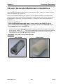
VACUUM GENERATOR MAINTENANCE GUIDELINES ............................................................................................. 6-11
CHAPTER 7
DRAWINGS ............................................................................................................................. 7-1
DRAWINGS .............................................................................................................................................................. 7-1
OVERVIEW ...................................................................................................................................................... 7-1
MECHANICAL ................................................................................................................................................. 7-1
ELECTRICAL ................................................................................................................................................... 7-1
PARTS LISTS ....................................................................................................................................................... 7-5
Overview............................................................................................................................................................ 7-5
www.exatron.com
iii
3/19/01
Chapter 1
Overview and Safety
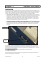
Please read and understand this entire Users’ manual before installing or using your Exatron handler.
The following safety procedures must be followed at all times.
Exatron Safety Features
MECHANICAL HAZARDS – BODILY INJURY HAZARDS
WARNING:
WARNING The Exatron model MSOP system uses servo-motor driven lead screws to move devices.
These motors are VERY POWERFUL and can cause SEVERE INJURY if the carriages or pick up
head pinch part of a human body or any extraneous item.
In order to avoid any such circumstance, the MSOP series is equipped with fixed and moving covers.
The fixed covers are screwed in place and should never be removed except for maintenance and only
then by qualified maintenance technicians. The moveable covers are supplied with interlocks. If the
cover is opened, power to the motors will be cut off and the motor will stop.
Exatron specifically disclaims responsibility and/or liability for any injury which occurs as a result of any
interlock being defeated and/or bypassed, or for any injury which occurs as a result of any fixed cover
being removed during operation.
COMPRESSED AIR
Your Exatron handler will require a compressed air supply. This handler should be supplied with
compressed air at between 80 (+/- 3 PSI) and will require 3 CFM for proper operation. The air supply
must be clean and dry to operate correctly. Dirty, oily or wet air will cause the vacuum generator to
malfunction and will make your system unreliable.
Using compressed air can be hazardous. It is the responsibility of the customer to properly train all
handler operators in every aspect of the safety practices associated with the use of compressed air.
NEVER operate any Exatron system which requires compressed air without an approved air
regulator and shutoff valve, such as that originally supplied with your system.
Exatron Support Services
Toll-Free Telephone Customer Service Line
For factory technical support, call 1-800-EXA-TRON, between 8:00 A.M. and 5:00 P.M. Pacific time,
Monday through Friday. When calling, please have your EXATRON equipment close at hand, along with
the following information:
z
z
z
The exact wording of any messages that appeared on your handler display.
A description of what happened and what you were doing when the problem occurred.
A description of how you tried to solve the problem.
www.exatron.com
1-1
3/19/01
Chapter 1
Installation
Standard Warranty
All EXATRON products are under warranty for one year from the date of purchase. EXATRON agrees to
repair any mechanical or electrical assembly, subassembly, or entire unit which fails during normal use
within its first year. The Customer agrees to follow the recommended maintenance procedure as defined
in the User's Manual.
EXATRON DOES NOT warrant test contactors. Handler test contactors are fragile and may be easily
ruined by operator abuse. EXATRON uses the finest materials available in our contactor designs.
All warranty work must be performed at the EXATRON factory or at an authorized Representative Service
location. As described on the following page, in-house service by our customers is encouraged.
EXATRON does not warrant the following:
1. Damage caused by improper packaging of equipment returned to EXATRON for repair.
2. Damage caused by the freight forwarder.
3. Damage caused by acts of God: flood, fire, earthquake, etc.
4. Damage caused by equipment connected to improper power line voltages.
5. Operator abuse.
6. Interface hardware not manufactured by EXATRON.
7. Test contactors.
8. Damage caused by equipment connected to improper air supply:contaminated with oil,water, dirt, etc.
AUTHORIZED CUSTOMER SERVICE CENTERS
EASTERN UNITED STATES:
JOHN TIERNEY
BOSTON MICRO
65 CARDIGAN ROAD
TEWKSBURY, MA 01876
(978) 640-1980 FAX: (978) 640-1968
EUROPE/U K:
ROY QUAIFE, PAUL CHANDLER
CHARNTEC ELECTRONICS
UNIT 9 PAXTON BUSINESS CENTRE
W HITTLE ROAD
CHURCHFIELDS INDUSTRIAL ESTATE
SALISBURY, W ILTSHIRE SP2 7YR
ENGLAND
011-44-1722-333389
FAX: 011-44-1722-416232
JAPAN:
KOJI YAOITA
DIRECTOR OF SALES
GENERAL BUSSAN CO., LTD.
2-18-2, NAKANO 2-CHOME
NAKANO-KU, TOKYO 164-0001
JAPAN
011-81-33-383-1711 FAX: 011-81-33-383-1719
www.exatron.com
1-2
3/19/01
Chapter 1
Installation
Customer In-House Service
Except in the case of Laser Marking Systems, EXATRON encourages customer in-house equipment
service and tries to make in-house service as easy as possible to perform. There are no "Void Warranty"
warning stickers on EXATRON handlers. EXATRON will even honor the warranty on a unit when an inhouse repair attempt leads to further damage to the unit. By using the built-in diagnostic software and
diagnostic tools, it is usually possible for the operator to isolate a problem quickly and effect a repair.
Offshore Warranty Service
An EXATRON Handler purchased in the United States and then shipped offshore will be warranted through
EXATRON in California. Replacement parts are furnished for a period of one year from date of purchase
with the exception of replacement contactors. In most cases, it will not be necessary to return the worn
part from the offshore user location.
To receive offshore service support, the handler must be purchased through your local EXATRON
Representative or an extended warranty agreement must be purchased directly from your local EXATRON
Representative.
Please supply the following information when requesting offshore service or replacement parts:
1. The part number(s) required. If the part number is not known, photocopy the part and fax it to
EXATRON.
2. The Model number of the Handler.
3. The type of device being run by the Handler, such as: DIP, SOIC, SOJ, PLCC, LCC, SIP,
PGA, PCB, ZIP, etc.
4. The Handler's serial number.
5. The full shipping address.
6. Any special shipping or customs instructions.
7. Method of shipment, such as: Federal Express, UPS, DHL, U.S. Mail, or the name of your
chosen freight forwarder.
In most cases, faxed requests and shipment of replacement parts orders are processed within twenty-four
hours of receipt by EXATRON.
www.exatron.com
1-3
3/19/01
Chapter 1
Installation
Also Available From Exatron:
The Model 3000B
with Eight Automatic Inputs
EXATRON'S eight-tube Octoloader is an ambient automatic eight-tube loader. The standard Model 3000B
comes equipped with this octoloader which is a moving metal plate holding up to eight tubes of devices,
controlled by the handler's CPU by means of a stepper motor. The plate automatically moves both left
and right, positioning each tube of devices over the handler input track. When the input track is emptied,
the octoloader automatically searches for tubes with devices. The octoloader has a sensor mounted at its
junction with the input track. The octoloader can "see" a device jam and stop its own movement to
prevent breaking the jammed device. The octoloader also has an automatic "wiggle" jam-clearing
operation which it will implement immediately in an effort to remove the jam without operator assistance.
Model 3000B octoloaders use a Snap-On plate which is specifically fitted with tube holders for a given
device application.
All Model 3000B Handlers not intended to be used on a "FRED," (Free Rolling EXATRON Dolly) are
supplied with bench-top base plates which must be bolted directly to a bench or table top to secure the
handler. Each plate includes two sets of tilt bars which enable the handler's tilt angle to be altered for
specific applications. The tilt angle is critical for ceramic DIPs and LCCs since too much drop angle may
cause chipping of the packages.
The Model 3010B
with One Elevated Temperature Track
The Model 3010B Hot Rail adds a single track hot rail to the input of the handler. This track holds twenty
inches of devices in order to preheat them prior to test. The temperature range of the Hot Rail is ambient
to +125° C. AC heaters are located within the Hot Rail. Exceptional temperature control is maintained by
constantly monitoring four points in the Rail and four points in the Test Site. The guaranteed accuracy is
±3° C everywhere in the Soak Rail and ±2° C in the Test Site. All four "zones" in the hot rail are
controlled by an EXATRON-designed computerized temperature controller.
The input of the Hot Rail has a manually operated two-input tube holder assembly.
All Model 3010B Handlers are supplied with a Free Rolling EXATRON Dolly ("FRED.") For operation, the
handler is to be mounted onto this floor stand which has four large tires for easy positioning and four floor
jacks to lock it into place.
www.exatron.com
1-4
3/19/01
Chapter 1
Installation
The Model 2000B
with Two-Tube Manual Input
The Model 2000B is an ambient handler with a manually operated two-input tube holder assembly for low
to mid-volume handling applications. The tube holder must be manually shifted when one tube of devices
empties in order to present another tube of devices to the input track. The Model 2000B uses Snap On
Change Over Kits to accommodate various size packages. The tube holders are custom-machined to a
specific tube size and are included as standard equipment with Model 2000B Snap On Change Over Kits.
All Model 2000B Handlers are supplied with bench-top base plates which must be bolted directly to a
bench or table top to secure the handler. Although smaller and less expensive than our Model 3000B,
the 2000B Series handlers are equipped with a broad range of features found in all EXATRON handlers
including:
• Wide Variety of Device Handling Capability
• Quick Changeovers Using Modified Snap-On Change Kits
• Variety of Interfaces
• Positive Binning
• Plunge to Board Test Contact Mechanism
• ESD Safeguards
The Model 5000
Series of Production Handling Systems
The 5000 Series of production handlers integrate any combination of customer-specified ambient
temperature programming/test sites, hot chamber(s), elevated temperature test site(s) and a "smart" laser
marking system. In addition, automatic tube loader/reloader components from various manufacturers
may be integrated into EXATRON'S Model 5000 when the laser marking system option is specified.
When equipped with a laser marker, the entire system is controlled by a single 80486/33 computer.
One or more test sites are available on all of the various Model 5000 configurations. The EXATRON
Model 5000 Series of Heavy-Duty Handling Systems are ideal for automating high-volume program, test,
and mark applications.
www.exatron.com
1-5
3/19/01
Chapter 1
Installation
Warning/Caution Labels
YOUR NEW EXATRON HANDLER WILL ARRIVE WITH SOME OR ALL OF THE FOLLOWING WARNING LABELS ATTACHED:
EXATRON
PART NUMBER
LABEL TEXT
LAB03-001
DANGER - INVISIBLE LASER RADIATION WHEN OPEN ...
LAB03-004
DANGER - ELECTRICAL HAZARD
LAB03-006
CAUTION - DO NOT OPERATE WITHOUT GUARDS ...
LAB03-007
DANGER - WATCH YOUR HANDS AND FINGERS
LAB03-008
CAUTION - BEFORE CLEANING OR SERVICING ...
LAB06-001
CAUTION - HIGH TEMPERATURE
LAB09-001
THIS UNIT SOLD AND SERVICED BY ...
LAB09-002
WARNING! DON'T REMOVE WITH HANDLER POWER ON
(IN-HOUSE ONLY)
THIS ORDER CONTAINS PARTICLE INTERCONNECT ...
5000-494
DANGER - DO NOT REMOVE OR DETACH ...
5000-958
CAUTION - HIGH PRESSURE AIR SOURCE
5000-967
CAUTION - CONTAINS HOT SURFACES
Availability of Warning Labels:
Current laws pertaining to the cautionary labels required to be installed on electronic equipment vary from
state to state. EXATRON makes every attempt to comply with all known labeling laws and safety
considerations as they relate to our component handling systems. In effect, virtually every surface of the
handler could be covered with warning signs and labels. For aesthetic reasons, we choose to produce a
machine with a less cluttered appearance, while still providing adequate visual caution indicators.
Individual customers may wish to obtain additional labels to facilitate safe operation and service for this or
other electronic equipment in use at their locations. The labels listed above may be purchased from the
EXATRON factory as desired. Our toll-free telephone number is 1-800-EXA-TRON.
www.exatron.com
1-6
3/19/01
Chapter 2
Handler Setup
HANDLER SETUP
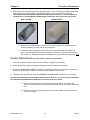
UNCRATE THE HANDLER
The Type 6 handler will usually come in a wooden crate which will require some disassembly to remove
the handler. Please inspect the system when it is removed from the crate for any obvious damage which
may be the result of shipping. Contact Exatron and the shipping company immediately should you see
any damage.
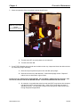
MOUNTING THE TEST SITE
Mounting the test site for the Type 6 handler is fairly simple. The test site interface board is shipped from
the factory already installed. Simply hookup the tester communication cable to the interface board.
PRESSURIZED AIR SOURCE
The MSOP system requires a supply of pressurized air at 80PSI (+/- 3 PSI). This air must be clean and
dry. The external air source should be attached to the air regulator mounted on the Handler base. Check
to make sure the air regulator gauge on the external regulator measures the air pressure at 80PSI, adjust
if necessary.
Exatron supplies the ¼ - 20 type “M” air fitting for the regulator.
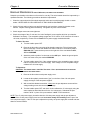
POWERING UP AND SYSTEM SETUP
1.
2.
3.
Turn the handler on. Do not load any parts into the system.
Wait. The servo motor will home and then set to the zero position.
Once the motor has zeroed, enter setup by pressing the [SETUP] key on the remote
microterminal.
MENU
The following menu describes the various handler setup features available from the front panel
microterminal interface. These setup features allow significant changes to be made to the operation of
the handler system.
!! EXERCISE EXTREME CAUTION WHEN CHANGING ANY SETTING FROM THE FRONT PANEL. IT
IS POSSIBLE TO SIGNIFICANTLY ALTER THE OPERATIONAL CHARACTERISTICS OF YOUR
HANDLER BY WAY OF THE FRONT PANEL.
Setup has three main categories:
1. Modifying the Setup of the system.
2. Resetting the Total Counts
3. Changing the RAM
These categories and their sub-categories are described briefly in the menu tree below. Further
information on these categories is available elsewhere in this manual. Appropriate references will be
included in the text.
A note on the syntax of the display messages: In some cases, the handler setup message will be in the
form of a question and then will be proposing and answer, thus: MOD SET UP ? NO. This question asks
www.exatron.com
2-1
3/19/01
Chapter 2
Handler Setup
whether to change any of the setup parameters of the handler, and it proposes the answer no. It is
possible to toggle the answer to such questions, and then accept those changed answers.
Also, any text within brackets [ ] indicates a key on the microterminal.
Example: [Enter] means to press the enter key.
Any messages on the display will be printed in reverse video.
Example: READY TO RUN
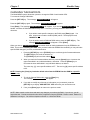
EXAMPLE OF MICROTERMINAL
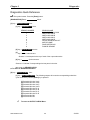
STARTING THE SETUP PROCEDURE
METHOD 1
Use this method when the handler is already powered on.
First make sure the display reads:
READY TO RUN
Depending on the status of the handler the display may also read:
EMPTY/LOAD PARTS or
EMPTY ALL TRACKS
The yellow light on the lightpole will be lit.
Now press the [SET UP] key on the microterminal.
The display will read CHANGE RAM? NO .
Press [Enter] .
The display will read RESET TOTALS NO .
Press [Enter] again.
The display will read MOD SETUP NO .
The [SETUP] key will toggle between MOD SETUP NO ? and MOD SETUP YS ?
Press the [SETUP] key to change the display to MOD SETUP YS ?
Press the [Enter] to start Modification Setup.
Now proceed with the instructions under the heading
www.exatron.com
MOD SETUP YS ? later in this chapter.
2-2
3/19/01
Chapter 2
Handler Setup
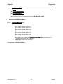
METHOD 2
To enter the setup menu from power up, do the following.
Turn the handler on. Do not load any parts into the system.
The display will do a self test and sign on.
V0 2.00 Test Ok
TYPE 6-2 02-14-01
The motor will then home.
HOME PICKUP
SERVO IS AT 0
The handler will then check that the index pickup sites are clear. If parts are present they will be picked
and transferred to the flush bin.
The display will then read: MOD SETUP NO ?
The [SETUP] key will toggle between MOD SETUP NO ? and MOD SETUP YS ?
Press the [SETUP] key to change the display to MOD SETUP YS ?
Press the [Enter] to start Modification Setup. Display will read T SITE = _ _ _ _ _
If the [Enter] or [SETUP] key is not pressed, the microterminal will “time out” in five seconds and proceed
to run mode. The display will read READY TO RUN .
Continue with the section entitled
www.exatron.com
MOD SETUP YS ? to complete setup.
2-3
3/19/01
Chapter 2
Handler Setup
MOD SET UP ? NO
There is a five second time out delay. If no action is taken within 5 seconds the handler will assume no
modification of the setup is necessary and will continue to READY TO RUN.
The settings which are accessed by this front panel selection determine certain handler operating
conditions, such as what interface to use in communicating with outside programmers or testers, whether
to stop when a failed device is detected, etc.
[SET UP] key toggles to MOD SET UP ? YS .
[Enter] key displays:
T SITE = _ _ _ _ _
This setup option sets the number of motor steps from the zero point to the test site. The factory
default is 46585.
Enter changes to the Test Site step count using the controller keypad number keys. The handler
allows changes to each digit from lowest to highest in order. First enter Ones, then Tens, then
Hundreds, etc.
For example: to enter a step count of 54321 devices, press [1], then [2], then [3], then [4], then
[5]. The display will read: T SITE = 54321 .
Press the [Clear] key to erase your entry.
Press the [Enter] key to set this number into memory and proceed to the next setup option.
FULL TUBE = _ _ _ _
This setup option sets the number of parts for a full output tube. The factory default is 0050.
Enter changes to the Full Tube count using the controller keypad number keys. The handler
allows changes to each digit from lowest to highest in order. First enter Ones, then Tens, then
Hundreds, etc.
For example: to enter a tube count of 4321 devices, press [1], then [2], then [3], then [4] .
The display will read: FULL TUBE = 4321 .
Press the [Clear] key to erase your entry.
Press the [Enter] key to set this number into memory and proceed to the next setup option.
PICK INTERFACE ?
[1] key chooses and displays: HANDLER PORT
[2] key chooses and displays: EXATRON SUPER
[3] key chooses and displays: EXATRON RS-232
[4] key chooses and displays: PROGRAM RS-232
(Please refer to Interface chapter of the manual for explanation of various interface options. )
[Clear] key rejects selection and returns to PICK INTERFACE ?
[Enter] key accepts selection and proceeds to STOP ON FAIL ?
www.exatron.com
2-4
3/19/01
Chapter 2
Handler Setup
STOP ON FAIL ?
[1] key chooses YES
[2] key chooses NO
[Clear] key rejects selection and returns to STOP ON FAIL ?
[Enter] key accepts selection and exits Setup mode.
The system is now ready to run parts.
RESET TOTALS NO
The handler maintains certain counts relating to the number of parts processed, etc. These counts are
stored in the RAM of the handler controller. Choosing this option will zero out these RAM counts, but will
not effect any of the RAM settings which can be set by the CHANGE RAM? option described later in this
chapter.
First make sure the display reads:
READY TO RUN
Depending on the status of the handler the display may also read:
EMPTY/LOAD PARTS or
EMPTY ALL TRACKS
The yellow light on the lightpole will be lit.
Now press the [SET UP] key on the microterminal.
The display will read CHANGE RAM? NO .
Press [Enter] .
The display will read RESET TOTALS NO .
[SET UP] key toggles to RESET TOTALS YS .
[Enter] key accepts reset command, briefly displays the message TOTALS SET TO 0, then
moves to MOD SET UP ? NO
www.exatron.com
2-5
3/19/01
Chapter 2
Handler Setup
CHANGING THE RAM DATA
The Model MSOP system allows the operator to change the RAM of each handler CPU.
To access the Change RAM Mode:
Press the [SET UP] key. The message CHANGE RAM? NO will appear.
Press the [SET UP] key again. The message CHANGE RAM? YES will appear.
Press [Enter]. The message LOAD DEFAULT NO will appear. If you choose LOAD DEFAULT NO, the
handler will leave all RAM addresses as they were. From here, you may proceed in either of two
directions:
a. If you wish to make specific changes to the RAM, press [Enter] again. You
have chosen not to load the default (ROM) values. The display will read,
“0090DATA 01”
b. If you do wish to set the RAM with ROM values, press the [SET UP] key. The
message LOAD DEFAULT YES will appear. Press [Enter].
When you choose LOAD DEFAULT YES, the handler loads all default addresses from the EPROM to the
RAM. This is called “Blasting the RAM” After you have loaded the EPROM into the RAM, you may still make
specific RAM changes if you wish, as described below.
1. Press the [SET UP] key or the [TOTALS] key to scroll through the firmware addresses:
The [SET UP] key will scroll the address up.
The [TOTALS] key will scroll the address down.
2. When you reach the firmware address desired, press the [Space] key to increment the
upper data nibble in any individual address, as desired. Press the [Delete] key to
increment the lower data nibble in any individual address, as desired.
The minus key, [–], sets a specific address to FF. The zero key [0], sets a specific address
to 00.
NOTE: Pressing the [Clear] key loads the default value from the EPROM into the RAM for a specific
address only.
3. To exit the Change RAM mode, press the [Enter] key.
The message MOD SET UP? NO will appear.
4. If you wish to modify any of the set-up information you just entered, press the
[SET UP] key to display “MOD SET UP? YES” and make your corrections now.
5. If not, press [Enter] again to return to the previous mode.
NOTE: Make certain to write down and retain any changes you make to the RAM. If you do not, you will
regret this later. Permanent selections should be programmed into the EPROM. Please contact Exatron for
assistance in doing so. Our toll-free telephone number is 1-800-EXA-TRON.
www.exatron.com
2-6
3/19/01
Chapter 2
Handler Setup
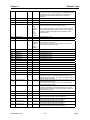
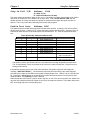
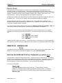
The following table describes each firmware address in numerical order. This information is
current as of the date of this manual. A system-specific RAM setting printout should appear at the
end of this chapter which will have the RAM settings as they were saved in the EPROM on this
system when it shipped from Exatron. As a result, some of the settings shown below may not
+agree with those on your system. Use the listing at the end of this chapter for settings specific
to your handler.
TABLE 1
Handler RAM
Adrs
Description
ROM
RAM Op
Comments
008F
Type6-2 02-14-01
1
N/A
Sign on message. Not to be modified by user.
0090
Handler Type
00
00
TYPE 6 Handler
0091
00
00, FF
FF= No sensor, 00 = Head up sensor present.
0092
Head Up Sensor
Option
Full Tube 1000s
30
30 to 39
0093
Full Tube 100s
30
30 to 39
0094
Full Tube 10s
35
30 to 39
0095
Full Tube 1s
30
30 to 39
Set the 1000s digit for number of devices constituting a full tube
(ASCII)
Set the 100s digit for number of devices constituting a full tube
(ASCII)
Set the 10s digit for number of devices constituting a full tube
(ASCII)
Set the 1s digit for number of devices constituting a full tube
(ASCII)
Index Precisor. On = 00, Off = FF
0096
Precisor On/Off
FF
00, FF
0097
Start Test Delay
10
00 to FF
0098
Start Pulse Width
14
00 to FF
0099
Remote Go
FF
00, FF
009A
Count Mask
00
00, 10
009B
Baud Rate RS-232
0C
009C
Data Format
07
009D
½ “ or 1” Pitch
00
See
Table in
Interface
Chapter
See
Table in
Interface
Chapter
00, FF
009E
Time Out
20
00, FF
009F
4
(ASCII)
6
(ASCII)
6
(ASCII)
1
(ASCII)
5
(ASCII)
00A4
Test Site Steps
10,000’s
Test Site Steps
1,000’s
Test Site Steps
100’s
Test Site Steps
10’s
Test Site Steps
1’s
Reserve A4
00A5
Reserve A5
00A0
00A1
00A2
00A3
www.exatron.com
Time delay for test site solenoids to close. Counts down in HEX
to determine the time delay in milliseconds.
Adjust the start test pulse width. This is allowed to provide
flexibility in interfacing between the handler and
tester/programmers. Counts down in HEX in 1 millisecond steps.
For EXATRON SUPER Interface only.
To run the system using the PC as the controller and EXATRONsupplied system software, set this address to 00. To run the
system without using the PC as the controller, set this address
to FF.
Allows the operator to designate a bin or bins that will ignore the
pre-defined full tube count. This is useful when using bulk/bucket
outputs.
For example, bit map 10 = Sort 5.
Stores the baud rate of the RS-232 interface between the handler
system and the PC.
Must be set to 0C for EXATRON SUPER Interface.
Stores the parity/stop/data bits.
Must be set to 03 for EXATRON SUPER Interface.
00 = 1” Pitch, FF = ½” Pitch.
A timed delay before the handler aborts the test and turns off all
solenoids. Counts down in HEX in 1 second steps. When this
address is set to 00, the system will never time out.
Set the 10,000’s digit for number of motor steps from zero point
to test site. (ASCII)
Set the 1,000’s digit for number of motor steps from zero point to
test site. (ASCII)
Set the 100’s digit for number of motor steps from zero point to
test site. (ASCII)
Set the 10’s digit for number of motor steps from zero point to
test site. (ASCII)
Set the 1’s digit for number of motor steps from zero point to test
site. (ASCII)
Not Used At This Time.
Not Used At This Time.
2-7
3/19/01
Chapter 2
Handler Setup
00A6
Check Sort Reset
FF
00, FF
00A7
Reserve A7
Enable the handler to check whether all sort signals are OFF at
the start of the test. To enable this option, set this address to 00.
To disable this option, set this address to FF. Set this to FF
especially when using LED checker boxes for simulation
purposes.
Not Used At This Time.
00A8
Reserve A8
Not Used At This Time.
00A9
Reserve A9
00AA
Stop on Fail Y/N
Not Used At This Time.
30
30, FF
See
Display
Dictionary
for
further
details.
Set to 30: Upon receipt of a fail signal from the tester, the handler
will place the device into the pre-assigned fail tube.
Set to FF: After the handler receives a fail signal from the tester,
the handler will stop with the contacts closed. This will allow the
operator to inspect contact alignment or increase/de- crease
contact pressure.
00AB
Reserve AB
Not Used At This Time.
00AC
Reserve AC
Not Used At This Time.
00AD
D Test ASCII Out
00AE
Reserve AE
Not Used At This Time.
00AF
Reserve AF
Not Used At This Time.
00B0
Reserve B0
Not Used At This Time.
00B1
Reserve B1
Not Used At This Time.
00B2
Reserve B2
Not Used At This Time.
00B3
Reserve B3
Not Used At This Time.
00B4
Reserve B4
Not Used At This Time.
00B5
Reserve B5
Not Used At This Time.
00B6
Reserve B6
Not Used At This Time.
00B7
Reserve B7
Not Used At This Time.
00B8
Reserve B8
Not Used At This Time.
00B9
Reserve B9
Not Used At This Time.
00BA
Reserve BA
Not Used At This Time.
00BB
Stop-Fail Sort
00
00 to FF
00BC
Double Test Sort
00
00 to FF
00BD
Send H on Retest
FF
00, FF
00BE
Reserve BE
00BF
Reserve BF
00C0
Sort 1 Bins 1-8
7F
00 to FF
00C1
Sort 2 Bins 1-8
80
00 to FF
00C2
Sort 3 Bins 1-8
80
00 to FF
00C3
Sort 4 Bins 1-8
80
00 to FF
www.exatron.com
D
See
Interface
Chapter
for
further
details.
This is the ASCII letter which the EXATRON RS-232 interface uses
as an output on a double test.
Set to S: Normal. Set to D: Handler will issue S on First Test
Cycle and D on Double Test Cycle.
Tells the handler which test sorts to stop operation on Fail signal
if desired. 00 = Stop on Fail feature is OFF for all sorts. FF =
Stops on Fail for ALL devices. FE = Sort 1 is PASS and all other
sorts are Stopped upon Fail.
Tells the handler which test sorts to double test if desired. 00 =
Double Test OFF for all sorts.
FF = Double Tests ALL devices. FE = Sort 1 is PASS and all
other sorts are Double Tested.
When this option is set to 00, the system will send an “H” signal
(initiating communication) to the tester at the start of a second
test of a device. When set to FF, the system will not send an “H”
before a second test cycle.
Not Used At This Time.
Not Used At This Time.
Input Sort 1 to handler output bins. BIT MAP.
Output cover LEDs will blink output sort locations.
Input Sort 2 to handler output bins. BIT MAP.
Output cover LEDs will blink output sort locations.
Input Sort 2 to handler output bins. BIT MAP.
Output cover LEDs will blink output sort locations.
Input Sort 2 to handler output bins. BIT MAP.
Output cover LEDs will blink output sort locations.
2-8
3/19/01
Chapter 2
Handler Setup
00C4
Sort 5 Bins 1-8
80
00 to FF
00C5
Sort 6 Bins 1-8
80
00 to FF
00C6
Sort 7 Bins 1-8
80
00 to FF
00C7
Sort 8 Bins 1-8
80
00 to FF
00C8
Reserve C8
00
Input Sort 3 to handler output bins. BIT MAP.
Output cover LEDs will blink output sort locations.
Input Sort 2 to handler output bins. BIT MAP.
Output cover LEDs will blink output sort locations.
Input Sort 4 to handler output bins. BIT MAP.
Output cover LEDs will blink output sort locations.
Input Sort 2 to handler output bins. BIT MAP.
Output cover LEDs will blink output sort locations.
Not Used At This Time.
00C9
Reserve C9
00
Not Used At This Time.
00CA
Reserve CA
00
Not Used At This Time.
00CB
Reserve CB
00
Not Used At This Time.
00CC
Reserve CC
00
Not Used At This Time.
00CD
Reserve CD
00
Not Used At This Time.
00CE
Reserve CE
00
Not Used At This Time.
00CF
Reserve CF
00
Not Used At This Time.
00D0
Reserve D0
00
Not Used At This Time.
00D1
Bit Check
00
00, FF
00D2
Interface Type
26
21, 23,
25, 26,
27
00D3
P/V/L
02
02, 04,
08
00D4
Reserve D4
00
For PROGRAMMER RS-232 Interface only.
Performs Illegal Bit Test at the start of the programming cycle.
00 = Bit Check ON.
FF = Bit Check OFF.
Sets default interface to be used by the handler.
21 = EXATRON SUPER Interface
23 = PROGRAM RS-232 Interface
25 = EXATRON RS-232 Interface
26 = HANDLER PORT Interface
27 = LOW GOING PULSE Interface
For PROGRAMMER RS-232 Interface only.
Selects Program, Verify, or Load Master operation.
02 = Program. 04 = Verify. 08 = Load Master.
Not Used At This Time.
00D5
Reserve D5
00
Not Used At This Time.
00D6
Reserve D6
00
Not Used At This Time.
00D7
Reserve D7
00
00D8
2nd Start Width
00
00D9
2nd Start Delay
00
Not Used At This Time.
00 to FF
Adjust the start test pulse width. This is allowed to provide
flexibility in interfacing between the handler and
tester/programmers. Counts down in HEX
Time delay for test site solenoids to close. Counts down in HEX
to determine the time delay in milliseconds
00DA
00DB
00DC
00DD
00DE
00DF
00E0
00E1
00E2
00E3
00E4
00E5
00E6
00E7
00E8
00E9
00EA
00EB
www.exatron.com
2-9
3/19/01
Chapter 2
Handler Setup
00EC
00ED
00EE
00EF
00F0
00F1
00F2
00F3
00F4
00F5
Pass Word On / Off
FF
00, FF
00 = Password On, FF = Password Off.
00F7
Cal Steps
34
(ASCII)
Set the 100’s digit for number of cal steps. (ASCII)
00F8
Cal Steps
31
(ASCII)
Set the 10’s digit for number of cal steps. (ASCII)
00F9
Cal Steps
30
(ASCII)
Set the 1’s digit for number of cal steps. (ASCII)
00FA
Accel 100’s
35
(ASCII)
Set the 100’s digit for motor acceleration. (ASCII)
00F6
00FB
Accel 10’s
34
(ASCII)
Set the 10’s digit for motor acceleration. (ASCII)
00FC
Accel 1’s
34
(ASCII)
Set the 1’s digit for motor acceleration. (ASCII)
00FD
Velocity 100’s
32
(ASCII)
Set the 100’s digit for motor velocity. (ASCII)
00FE
Velocity 10’s
30
(ASCII)
Set the 10’s digit for motor velocity. (ASCII)
00FF
Velocity 10’s
30
(ASCII)
Set the 1’s digit for motor velocity. (ASCII)
www.exatron.com
2-10
3/19/01
Chapter 3
Interface Information
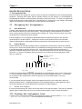
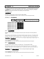
OVERVIEW
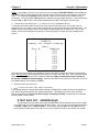
The test site on the Handler may be interfaced to virtually any programmer and/or tester available. Some
interfaces require custom configuration prior to shipment but the only requirement for a given programmer
or tester is that it be capable of issuing and accepting commands to and from the handler or the system
controller. There are two basic parts to the handler's interface with your programmer/tester.
1. The first part is the "DUT Interface." The DUT Interface connects the handler's test contacts to the
tester's test socket. There are many ways to accomplish this, depending upon application and type of
changeover kit. A direct dock interface which connects the tester directly to the handler contacts
provides the best performance, although other interface methods are available. In most cases, the
hardware required for the DUT Interface will be built and installed at EXATRON. Therefore, the DUT
Interface will not be discussed in this section of the user's guide.
2. The second basic part to every interface is the "Control Interface." The Control Interface allows
the handler to send a Start to the tester and subsequently allows the tester to instruct the handler how
to process the device under test. The handler is equipped with a variety of ways to accomplish this
task using two basic means of access: a parallel port (EXATRON’S “Handler Port”) and an RS-232
serial port.
RS-232 PORT
HANDLER
PORT
The handler has a number of operating features which relate to the handler's tester control interface.
Both the Handler Port and RS-232 Port have several distinctive options from which to choose. These
various control interfaces available from EXATRON are the subject of the following discussion. They have
been organized into three categories:
A. General Interface Options, (common to both Handler Port and RS 232 Port)
B. Handler Port Interface Options.
C. RS-232 Interface Options.
Please read through all of the firmware options in this chapter to determine exactly which interface will
meet your specific application requirements.
www.exatron.com
3-1
3/19/01
Chapter 3
Interface Information
General Interface Options and Set Up
Accessing a Handler Control Interface:
When the handler powers up, you will be given the opportunity to, PICK INTERFACE? If you press the
[Enter] button, the previously selected interface (or default interface, if RAM was cleared) will be
selected. Listed below are the standard interfaces currently supplied with the handler. NOTE: New
interfaces are added to the handler from time to time. Please contact EXATRON for updates as required.
Our toll-free telephone number is: 1-800-EXA-TRON.
From “PICK INTERFACE?” displayed on the front panel:
PICK INTERFACE ?
[1] key chooses and displays: HANDLER PORT
[2] key chooses and displays: EXATRON SUPER
[3] key chooses and displays: EXATRON RS-232
[4] key chooses and displays: PROGRAM RS-232
(Please refer to Interface chapter of the manual for explanation of various interface options. )
[Clear] key rejects selection and returns to PICK INTERFACE ?
[Enter] key accepts selection.
General Interface RAM Selections:
Listed below are addresses in the handler’s battery backed-up RAM which may be edited to fine tune the
handler for your specific programmer/tester and sorting requirements when using either the Handler Port
(parallel) or the RS-232 serial port. These addresses are not part of the standard power-up selections
and may be modified only by “Changing The RAM,” as described in the Handler Set-Up Chapter of
this manual.
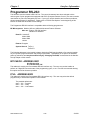
Interface Type:
Address 00D2
This address allows the user to set the default interface to be used by the handler. The following table
lists available settings:
data setting 21
data setting 23
data setting 24
data setting 25
data setting 26
data setting 27
Start Test Delay:
=
=
=
=
=
=
EXATRON SUPER
PROGRAM RS-232
LASER ONLY KIT [MODEL 5000 ONLY.]
EXATRON RS-232
HANDLER PORT
LOW GOING PULSE [USES SPECIAL PAL A89-2LP.]
Address 0097
For DIP devices only, this delay adds "settling" time to the DUT. The delay allows the DUT more time to
come to rest in the test site before the contacts close. The delay counts down in HEX, in 1 millisecond
steps.
www.exatron.com
3-2
3/19/01
Chapter 3
Stop On Fail Y/N:
Interface Information
Address
00AA
30 = Stop on Fail
FF = Run Failed Devices, No Stop
This option allows the handler to Stop on Fail, or not. The handler can either automatically cycle a failed
device into an output tube or the handler can be set to stop. If set to STOP ON FAIL YES, then the
handler will stop on a failure and allow the operator to retest the device again and again, as often as
desired. This is very useful when calibrating test fixtures and programs.
Double Test Sort:
Address 00BC
This address tells the handler which test sorts to double test if desired. A setting of “00” will turn off the
double test for all sorts. A setting of “FF” will set the tester to double test all devices. Assuming Sort 1 is
Pass and all other sorts are to be double tested, set this address to “FE.” Each bit represents a tester
sort.
Tester Sort Set Up: Addresses 00C0 to 00C7
ASCII INPUT
SORT
OUTPUT BINS
CURRENT SETTING
1
1
RAM ADDRESS C0
2
2
RAM ADDRESS C1
3
3
RAM ADDRESS C2
4
4
RAM ADDRESS C3
5
5
RAM ADDRESS C4
6
6
RAM ADDRESS C5
7
7
RAM ADDRESS C6
8
8
RAM ADDRESS C7
✻
USED BY EXATRON RS-232
=
Remote Flush
AND H P RS-232 ONLY
0
USED BY EXATRON RS-232
=
Remote Retest
AND H P RS-232 ONLY
The handler uses the specifications shown in the table above to assign Output Bins to tester Sorts.
The “Current Setting” column is provided for the customer’s reference purposes. Please enter your
settings in this column.
If the handler does not receive one of the above test Sorts, the handler will pause and display the
message, “BAD TEST RESULT.” The handler will output the HEX equivalent of the actual character
received by the handler to the LEDs on the handler’s output shuttle cover. LED #1 is bit 01, LED #8 is bit
80. Pressing the [Clear] button on the handler’s front panel will flush the device from the test site and
restart operation. Press [Enter] to retest, if desired.
When the handler does receive a proper result in the form of one of the above test Sorts, the handler will
open the test contacts and flash the output cover LED of the output bin selected. The handler will sort the
DUT accordingly and start a new handling cycle.
www.exatron.com
3-3
3/19/01
Chapter 3
Interface Information
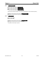
Handler Binning Setup
I.Introduction:
EXATRON handlers are designed to accept as many as eight sort messages from your tester/programmer
equipment. Selecting which output bins the handler will then put your devices in is accomplished by
programming the handler to match physical output bins to tester sort results. The tester sort signals will
come into the handler via the Parallel Port or the RS232 Port. Please refer to the Interface Information
chapter of this manual for further reference on tester-handler communication.
II. Designing Bin Assignments:
A.
Pass, Retest, Fail
Typically, there are three main categories of test results: devices that pass test, devices that definitely fail
test, and devices that may or may not have failed. This last category is best understood as continuity
errors, missed contacts, devices in test during power outages, etc. These are devices which may in fact
be good devices but which need to be retested.
If the test program in use is designed to differentiate between fail and retest devices, then EXATRON
recommends bin 5 as the retest bin. Assign bins 4 and/or 6 as the positive fail bins in this situation.
Where no differentiation is made between fail and retest devices, then assign bin 5 for these devices.
B.
Positive Binning
Positive binning is the concept of designing the bin assignments to minimize the ill effects of accidental
binning errors. All EXATRON handlers have very substantial mis-binning protection built in. It is impossible
to say absolutely that no mis-bins will ever occur. As a defense against accidental mis-binning, it is
generally considered bad practice to carry “fail” or “retest” devices to their bins over the tops of any good
device bin. It is better to accidentally drop a good device in a fail bin than to accidentally drop a failed
device in a good bin.
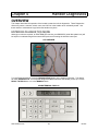
Output from
handler.
Shuttle, moves over
b
1
2
3
4
5
Bins
( b
6
)
7
8
Outside
Inside
Outside
Looking at the above diagram, it would be inappropriate to put anything but “retest” or “fail” devices in bin
5. If bin 5 is assigned as a good bin, then some other bin must be assigned as a fail bin. It would then
be necessary to carry a failed device across the good bin 5 to some other location. This is not
recommended.
If your test results provide for grades, then the best grades should be in the outside bins, with lower
grades toward the inside. If a highest-rated device is accidentally dropped in a lower-grade bin, that is
not as bad a problem as if a lower grade device is dropped in a higher-grade bin.
C.
Unused Sort Signals
It is wise to always assign the “retest” tube as the output for unused sort signals. This acts as a defense
against “ghost” signals which may occur as a result of tester interface “noise” or power fluctuations.
III. Finding Bin Assignment Data:
To figure out the correct binning data for your desired tube outputs, please consult the “ Test Signal
- Bin Sort Data Worksheet” which accompanies this document.
www.exatron.com
3-4
3/19/01
Chapter 3
Interface Information
IV. Storing Bin Assignments in Handler Memory:
The handler uses a look-up table to assign handler output bins/tubes to tester sort signals. The output
tube parameters are stored as a two digit hexadecimal number in the handler’s memory (e.g.: “E5”). The
first digit describes what happens with tubes numbered five through eight, and the second digit describes
what happens with tubes numbered one to four. The first digit is called the “Most Significant Bit” and the
second, the “Least Significant Bit.”
You will need to edit the memory addresses in the handler’s battery backed-up RAM to store your desired
binning data. A chart with all relevant memory addresses is shown at the end of this document and on
the Test Signal - Bin Sort Data Worksheet.
To edit the Handler memory from the front panel display, follow this procedure:
1.0 Make sure you have a copy of the EXATRON-supplied RAM address listing for your system. While
most handlers store the binning information as described in the chart on the worksheet, some custom
handlers have variations in addresses. A copy of this address listing is in the supplemental chapter at
the end of this manual.
2.0 Verify that the handler is in Manual Mode. Display will read MANUAL MODE.
3.0 Press the [SET UP] key. Display will read CHANGE RAM ? NO.
4.0 Press the [SET UP] key. Display will read CHANGE RAM ? YES.
5.0 Press the [Enter] key. Display will read LOAD DEFAULT ? NO.
6.0 Press the [Enter] key. Display will read 0090 DATA 01 The handler is now in the edit mode of the
handler’s battery backed-up RAM.
7.0 Press the [SET UP] key to increment the address. The [TOTALS] key will decrement the address.
8.0 Press the [SET UP] key until address 00C0 is displayed. Display will read 0C0 DATA xx, where xx
is the hexadecimal data at that address. Address 00C0 is the address where data for Sort Signal 1 is
stored on standard handlers. Note that LEDs on the output door are now flashing. The flashing lights
indicate which tubes are currently selected for Sort 1. If you change the data, the flashing lights will
change as well. Use this visual confirmation for the tubes you have selected.
9.0 If necessary, change the data at this address:
9.1
9.2
9.3
9.4
9.5
Press the [Space] key to increment the first data digit (the most significant data bit.)
Press the [Delete] key to increment the second data digit (the least significant data bit.)
Press the “ [0] ” key to set the data at that address to 00.
Press the “ [ – ] ” key to set the data at that address to FF.
Press the [Clear] key to load the EPROM default data at that address.
10.0
When finished editing this address, press the [SET UP] key until the next relevant address is
shown. Consult the handler memory address chart below.
11.0
Edit this address as described above in section 9.0.
12.0
Continue this process until all addresses have been changed to proper data. Note that if your
tester/programmer uses less than eight signal outputs, you should assign the fail bin to all
remaining sort signals.
13.0
When finished editing, press the [Enter] key to exit editing and set the new DATA into RAM.
www.exatron.com
3-5
3/19/01
Chapter 3
Interface Information
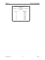
Memory addresses in
handler
memory for output binning
data:
Sort #
Address
1
00C0
2
00C1
3
00C2
4
00C3
5
00C4
6
00C5
7
00C6
8
00C7
www.exatron.com
3-6
3/19/01
Chapter 3
Interface Information
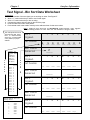
Test Signal - Bin Sort Data Worksheet
Instructions:
1. Write the number of the sort signal you are working on under “Sort Signal #”.
2. Write a “1” under each tube you wish to use for that signal.
3. Write a “0” under each tube you are not using.
4. Compare the pattern with the chart on the left of the page.
5. Enter the Data result under each pattern.
6. Put that data result in the handler memory at the address shown for that sort number.
Note: Tube #s are written in DESCENDING order below; they appear
in ascending order on the face of the handler output door.
This example shows how to
derive binning data. Using
bins 1, 3, 7 & 8, the binning
data is C5. Consult handler
chart (bottom) for proper
address.
C
O
M
P
A
R
E
Compare the
pattern from
the
worksheet
with this
chart to
determine
hex data:
Pattern
Data
0000 0
0001 1
0010 2
0011 3
0100 4
0101 5
0110 6
0111 7
1000 8
1001 9
1010 A
1011 B
1100 C
1101 D
1110 E
1111 F
Sort
Signal
Patterns
8
7
W
R
I
T
E
I
N
Memory addresses in
handler memory for sort
binning data:
Sort # Addr.
1
00C0
2
00C1
3
00C2
4
00C3
5
00C4
6
00C5
7
00C6
8 www.exatron.com
00C7
5
4
3
2
1
1 __
0 __
0 __
0 __
1 __
0
1 __
__
Hex Data
Numeral
Sort
Signal
Patterns
6
C
____
8
7
6
1
5
____
5
4
3
2
1
__ __ __ __ __ __ __
Hex Data
Numeral
Sort
Signal
Patterns
8 7
Hex Data
Numeral
Sort
Signal
Patterns
____
8
7
6
____
5
4
3
2
1
__ __ __ __ __ __ __
6 5 4 3 2 1
____
8
7
6
____
5
4
3
2
1
__ __ __ __ __ __ __
3-7
3/19/01
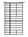
Chapter 3
Sort
Signal
Patterns
Interface Information
8
7
6
5
4
3
2
1
__ __ __ __ __ __ __
Hex Data
Numeral
Sort
Signal
Patterns
____
8
7
____
6
5
4
3
2
1
__ __ __ __ __ __ __
Hex Data
Numeral
Sort
Signal
Patterns
____
8
7
____
6
5
4
3
2
1
__ __ __ __ __ __ __
Hex Data
Numeral
Sort
Signal
Patterns
____
8
7
____
6
5
4
3
2
1
__ __ __ __ __ __ __
Hex Data
Numeral
Sort
Signal
Patterns
____
8
7
____
6
5
4
3
2
1
__ __ __ __ __ __ __
www.exatron.com
3-8
3/19/01
Chapter 3
Interface Information
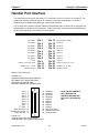
Handler Port Interface
THE HANDLER PORT INTERFACE USES SIMPLE TTL-COMPATIBLE SIGNALS TO CONTROL THE HANDLER. This
parallel port interface utilizes the 24 pin “D” connector on the side of the handler. It has been
designed to be compatible with “MCT-type” tester control interfaces.
The HANDLER PORT interface uses the addresses 00C0 through 00C7 for tester sort to output bin and
address 00BC for double test on/off selection. Please refer to the General Interface RAM Selections
section at the beginning of this chapter for further details.
Handler Port Pin Out:
Sort Input 1
Sort Input 2
Sort Input 3
Sort Input 4
Sort Input 5
Sort Input 6
Sort Input 7
Sort Input 8
2nd Start
Output 1, Start Test: Pulse
Handler Vcc, +5 VDC
Handler Ground
Pin 1
Pin 2
Pin 3
Pin 4
Pin 5
Pin 6
Pin 7
Pin 8
Pin 9
Pin 10
Pin 11
Pin 12
Pin 13
Pin 14
Pin 15
Pin 16
Pin 17
Pin 18
Pin 19
Pin 20
Pin 22
Pin 22
Pin 23
Pin 24
Input 9, End of Test
Not Used
Not Used
Not Used
Output 8
Output 7
Output 6
Output 5
Output 4
Output 2, Start Test: Level
Handler Vcc, +5 VDC
Handler Ground
SPECIAL PAL REQUIRED
FIGURE 3-1A
HANDLER INTERFACE PORTS DETAIL
OPTIONAL OPTO ISOLATION PORT
SEE 5000-D76 FOR DETAILS
MATING CONNECTOR T&B #609-2030
Sort 1 1
Sort 2 2
Sort 3 3
Sort 4 4
Sort 5 5
Sort 6 6
Sort 7 7
EOT 8
nd
2 Start 9
Start Test Pulse 10
Handler Vcc +5VDC 11
Tester Ground 12
13
14
15
16
17
18
19
20
21
22
23
24
Not Used
Not Used
Not Used
Not Used
Output 8
Output 7
Output 6
Output 5
Output 4
Start Test Level
Handler Vcc+5VDC
Tester Ground
NOTE: NEVER CONNECT
OPTO GROUND TO
HANDLER GROUND OR
OPTO Vcc TO HANDLER
Vcc
FIGURE 3-1B
HANDLER INTERFACE PORTS DETAIL
HANDLER PORT SEE 5000-A89 FOR DETAILS
www.exatron.com
3-9
3/19/01
Chapter 3
Interface Information
MATING CONNECTOR CINCH #57-30240
Sort 1 1
Sort 2 2
Sort 3 3
Sort 4 4
Sort 5 5
Sort 6 6
Sort 7 7
Sort 8 8
nd
2 Start 9
Start Test Pulse 10
HandlerVcc +5VDC 11
Handler Ground 12
13
14
15
16
17
18
19
20
21
22
23
24
Input 9 EOT
NOTE: NEVER CONNECT
Not Used
TESTER Vcc TO
Not Used
HANDLER Vcc
Not Used
Output 8
Output 7
Output 6
Output 5
Output 4
Start Test Level
HandlerVcc +5VDC
Handler Ground
REMEMBER:
1. Use the 24-pin handler port.
2. All signals are TTL/CMOS compatible.
3. Opto-isolation is available as an optional feature except on the 2000B
Series Handlers. To obtain this feature for your Model 3000B or Model
5000 Handler, please specify your request at the time of placing your
handler order.
Additionally, all 3000B and 5000 Series Handlers may be upgraded to
opto-isolation in the field. To order this upgrade for an existing handler,
contact the EXATRON Sales Department and order PCB #5000-D76,
"Opto Isolation Interface/Light Pole Option PCB." Our toll-free telephone
number is 1-800-EXA-TRON.
4. The +5 volt output on the handler port (Pins 11, 23) is NOT to be used by or connected to
the tester, unless it is isolated at the tester.
5. Pins 12 and 24 are ground connections.
6. Refer to FIGURE 3-2 following, for timing diagram.
For further timing/sort details, please refer to DRAWING #5000-F62.
www.exatron.com
3-10
3/19/01
Chapter 3
Interface Information
FIGURE 3-2
HANDLER PORT INTERFACE Timing Detail
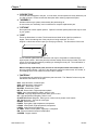
The handler first moves a device into the test site. After allowing time for the device to settle, (NOTE:
this settling time is programmable; use address 0097) the test head plunger picks up the device and
plunges it down toward the contactors. Then the handler issues a start pulse (Pin 10) to the tester. The
start pulse width is programmable, (address 0098) but will be pre-set to 20 milliseconds. This pulse is
normally High (+5) and goes Low for the pulse width. There is an additional signal available on Pin 22.
This testing signal will go Low for the duration of the test. It will go Low at the start of the start pulse and
will not go High again until the handler receives a sort signal.
SORT MUST BE STABLE FOR 1 MSEC MINIMUM PRIOR TO EOT
PULSE OR LEVEL
HANDLER ALLOWS ONLY
ONE SORT INPUT PER TEST
ALL HANDLER INPUTS AND
OUTPUTS STANDARD
TTL LOGIC
NORMALLY HIGH
ACTIVE LOW
20 MSEC
ADJUSTABLE
TEST TIME
INDEX / SORT TIME
To complete the test, the tester must send back one of eight sort signals. These signals must be normally
High and go Low for at least two milliseconds. The sorts must appear on Pin 1 through Pin 8 on the
handler port connector. We recommend that you use Pin 1 for PASS and Pin 2 for FAIL when using the
handler in PASS/FAIL applications.
The Input Sort is connected to a PAL device which "latches" the signal. The latch sets the falling edge of
the sort signal ON. Make certain that your interface does not allow fast "glitches" which may become
latched, causing the handler to mis-sort. If desired, the PAL may be modified to one that requires an
"End of Test" edge as well. Further details are provided in the Handler Port Options section later in this
chapter.
To abort the test, press the [Clear] button on the handler controller. This will sort the DUT to the Home
bin, output tube 5.
www.exatron.com
3-11
3/19/01
Chapter 3
Interface Information
Once the handler receives a sort pulse, it checks that:
1. The sort has a corresponding output. If not, you will see:
NO SORT ERROR displayed, advising that there are no outputs available.
2. Only one sort has been received. Only one sort signal is allowed. If multiple sorts were
received, you will see: MULTI SORT ERR displayed. The output shuttle cover LEDs will blink
the pattern of the actual sorts latched by the handler. Two or more LEDs will blink, indicating
the multiple sort error.
If the received sort pulse is acceptable, the contacts will open and the device will be sorted to an output
tube. Or, in the case of plunge-to-board changeover kits, the test site plunger will pick up the device and
rise to its highest point. From there, the device will be sorted to an output tube.
Handler Port Options:
EOT (END OF TEST)
The handler port is controlled by two PAL devices. These PALs control the polarity of the
handler's input/output signals and whether "EOT" is to be used or not. The EOT input (pin 13) is not
active unless the correct PAL is installed on the handler’s Front Panel Card #5000-A89. The EOT
signal, when used, will cause the handler to ignore all tester sort input signals until the EOT (normally
High, active Low) is received by the handler.
PAL 101-12.JED (Sum check 76B0) = No EOT signal required.
PAL 101-12EOT.JED (Sum check 75B0) = EOT signal required by the handler.
CORRECT PALS MAY ALWAYS BE OBTAINED FROM EXATRON AT NO CHARGE.
Listed below are addresses in the handler's battery backed-up RAM which may be edited to fine-tune
the handler for your specific programmer/tester and sorting requirements. These addresses are not
part of the standard power-up selections and may be modified only by “Changing The RAM,” as
described in the Handler Set-Up Chapter of this manual.
START PULSE WIDTH: ADDRESS 0098
This delay controls the Start of Test pulse width. The delay counts down in HEX, in 1 millisecond
steps. The standard default is "14." This sets the start test pulse width to 20 milliseconds. On
interfaces using a PC to control the handler, a longer start pulse width may be required to guarantee
that the PC sees the start test pulse from the handler.
CHECK SORT RESET: ADDRESS 00A6
00 = On
FF = Off
The Check Sort Reset feature should always be used on handlers which are employing the
Handler Port interface. This check verifies that all Sort signals to the handler are turned off at the end
of the Start pulse (all Sorts are at Logic High.)
Occasions may arise during operation of the Handler Port interface when the handler sends a Start
pulse to the tester but the tester either does not see the Start signal, or the tester fails to clear the
previous Sort signal. In the latter case, the previous Tester Sort signal is still active at the end of the
Handler's current Start pulse. The handler correctly responds to the previous Sort signal, which
means that the current device under test (DUT) will not be tested and will be mis-sorted. It may
appear to the operator that the handler is making an error, when in fact the tester has made an error.
Therefore, it is a good idea to set this check to On whenever your application allows for it.
www.exatron.com
3-12
3/19/01
Chapter 3
Interface Information
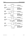
SECOND START PULSE FEATURE
2ND START WIDTH: ADDRESS 00D8
2ND START DELAY: ADDRESS 00D9
ND
Exatron has added a “2 START PULSE” to the EXATRON Handler Port interface. This second
start pulse is to be used in the event that the tester you wish to use has a problem with the handler’s
ND
standard start pulse timing. Use this “2 START PULSE” only to solve interface problems flagged by
the error messages: SORT NOT RESET and/or MULTI SORT ERROR.
♦
For correct use of the handler’s standard start pulse, the tester must reset all sort signals to Logic
High on the leading/falling edge of the standard start pulse. The handler resets its input sort latch on
the rising edge of the start pulse. At that instant in time, if any sort signals are still present from the
tester, they will be latched into the handler’s sort latch. This could cause the handler to sort an
untested device to an output bin based on the previous tester bin result. In many cases, the
mechanical motion of the handler will allow both the previous bin result plus the new bin result to be
latched into the handler’s sort latch. This will result in a MULTI SORT ERROR message. The
handler’s output cover LEDs will flash the input error combination. Typically, a Pass and a Fail input
will flash at the same time.
♦
It may be that your tester does not respond to either edge of the handler’s start pulse. This is a
common problem with PC-based testers. In this case, making the standard start pulse longer may
correct the problem.
♦
It may be that your tester resets the sorts on the rising edge of the handler’s standard start pulse. In
this case, making the standard start pulse longer will have no effect. You now have the option to use
ND
the “2 START PULSE.” You may, from the handler’s front panel, adjust the second start pulse to
start before the standard start pulse, and/or end after the standard start pulse. You may now use the
rising edge of the second start to reset the tester, independent of the rising edge of the standard start.
Care must be taken to be absolutely sure that the tester’s sorts are completely reset before the end of
the start pulse used by the tester.
ND
Please refer to FIGURE 3-3 on the following page for timing diagrams of several “2 START” set up
examples. If you are having interface problems, please call the EXATRON factory for free customer
service advice. Our toll-free telephone number is: 1-800-EXA-TRON. EXATRON cannot be held
responsible for mis-sorted devices when the tester’s sort signal timing is not correctly set up and fully
understood by the customer.
FIGURE 3-3
www.exatron.com
3-13
3/19/01
Chapter 3
www.exatron.com
Interface Information
3-14
3/19/01
Chapter 3
Interface Information
RS-232 Interfaces
EXATRON SUPER ~ EXATRON RS-232 ~ H P RS-232 ~ PROGRAMMER RS-232
RS-232 Port Options:
Listed below are addresses in the handler's battery backed-up RAM which may be edited to fine tune
the handler for your specific programmer/tester and sorting requirements. These addresses are not
part of the standard power-up selections and may be modified only by “Changing The RAM,” as
described in the Handler Set-Up Chapter of this manual.
BAUD RATE
009A
__
009A
009A
009A
009A
009A
009A
009A
06
0C
18
30
60
C0
80
This address stores the baud rate setting for the RS-232 serial port. The RS-232
port uses the 25 pin RS-232 connector on the side of the handler.
19200 Baud
9600 Baud [Default setting]
4800 Baud
2400 Baud
1200 Baud
600 Baud
300 Baud
DATA FORMAT
009B
009B
009B
009B
009B
009B
009B
009B
009B
009B
009B
009B
009B
009B
009B
009B
009B
009B
009B
009B
009B
__
02
2A
3A
1A
0A
06
2E
3E
1E
0E
03
2B
3B
1B
0B
07
2F
3F
1F
0F
www.exatron.com
This address stores the data format setting for the RS-232 port.
No parity
7 Data 1 Stop
Stick one
7 Data 1 Stop
Stick zero
7 Data 1 Stop
Even parity
7 Data 1 Stop
Odd parity
7 Data 1 Stop
No parity
7 Data 2 Stop
Stick one
7 Data 2 Stop
Stick zero
7 Data 2 Stop
Even parity
7 Data 2 Stop
Odd parity
7 Data 2 Stop
No parity
8 Data 1 Stop [Default setting]
Stick one
8 Data 1 Stop
Stick zero
8 Data 1 Stop
Even parity
8 Data 1 Stop
Odd parity
8 Data 1 Stop
No parity
8 Data 2 Stop
Stick one
8 Data 2 Stop
Stick zero
8 Data 2 Stop
Even parity
8 Data 2 Stop
Odd parity
8 Data 2 Stop
3-15
3/19/01
Chapter 3
Interface Information
Exatron Super
The Exatron Super interface allows for computer control of the handler, tester/programmer, and
label/laser marker as a complete system. This interface uses the handler’s RS-232 Control Port to
communicate with the controlling computer running Exatron E5000 laser software or Exatron Label Maker
software. The actual connection to the computer is usually COM1, COM3, or the first port on the
Digiboard I/O box. This may vary depending upon your handler's configuration.
All aspects of production are controlled by the computer carrying out instructions as they are defined in a
file called a "Job." Job files may be created, edited and saved as desired by the operator.
All serial connections are 25 pin to 25 pin “straight through.” If a special cable is needed for your
programmer/tester, please provide Exatron with the pin out configuration or the cable itself, so that we
may furnish compatible interface hardware.
The communications settings are fixed in the firmware at 9600 Baud, No Parity, 8 Data Bits, 1 Stop. All
serial devices connected to the Exatron controlling computer should be so configured.
The connector on the handler is a 25 pin RS-232-type “D” connector with female pins. The mating
connector on the interface cable must use male pins. The RS-232 side panel port uses the following
pins:
Pin 1 = GROUND
Pin 2 = RECEIVE; input to handler
Pin 3 = SEND; output from handler
Pin 7 = GROUND
Typically this cable is wired one to one (1 : 1) to the RS-232 port on the back of a PC using a 25 pin RS232 connector. If your PC uses a 9 pin RS-232 port, then, typically use a straight through interface cable.
REMOTE GO: ADDRESS 0099
00 = On
FF = Off
This address must be set to On for the controlling computer to have access to the handler's RAM. If this
address is not set properly, the handler will display the message: WAITING FOR PC.
EXATRON SUPER RS-232 CONTROL COMMANDS: [5000 SERIES ONLY.]
This information is subject to change without notice. Contact EXATRON for latest revision. The following
RS-232 control commands are used by the EXATRON 5000 Series Handlers. The handler must be set to
use the EXATRON Super interface only. These commands do not apply to the handler’s Programmer
RS-232 interface, or EXATRON RS-232 interface, or to any other RS-232 interface.
For firmware: “5000FAST”
TEST [CR]
The handler has loaded a device into the test site. (The top test site in dual site
handlers.) The tester should now start testing the DUT for the first time. No answer is
required. Do not send the End Of Test (EOT) sort until the handler specifically asks for
END TEST [CR].
www.exatron.com
3-16
3/19/01
Chapter 3
Interface Information
END TEST [CR]
Requests the End Of Test (EOT) sort for the DUT in the test site.
The handler must receive an answer before continuing operation. Send back a single
ASCII character. The only legal answers are the numbers 1 through 8.
Example: for Sort 1, PASS, send a “1”
for Sort 2, FAIL, send a “2”
RETEST [CR]
The handler has unloaded a device from the contacts and has reinserted it for a double
test operation. (The top test site in dual site handlers.) The tester should now begin
testing the same DUT for the second (or multiple) time. No answer is required. Do not
send the EOT sort until the handler specifically asks for END RETEST [CR].
END RETEST [CR]
Requests the End Of Test (EOT) sort for the DUT(s) in the test site. The handler must
receive an answer before continuing operation. Send back a single ASCII character.
The only legal answers are the numbers 1 through 8.
Example: for Sort 1, PASS, send a “1”
for Sort 2, FAIL, send a “2”
ERROR [CR]
The handler has received a command, but the command was not understood or is not one of
the legal commands used by the handler. No answer is required, but if you want the handler
to perform some operation, then retry your previous command.
www.exatron.com
3-17
3/19/01
Chapter 3
Interface Information
COMMANDS FROM THE PC TO THE HANDLER:
1 [CR] = SORT 1
2 [CR] = SORT 2
3 [CR] = SORT 3
4 [CR] = SORT 4
5 [CR] = SORT 5
6 [CR] = SORT 6
7 [CR] = SORT 7
8 [CR] = SORT 8
+ (plus) = Put handler in Listen mode.
+ A90 [CR] = Ask handler to send a specific EPROM/RAM address setting:
“?? ROM ?? RAM ??”
+ B [CR] = Reset all handler tube/total counters to zero.
Handler display will read, TOTALS SET TO 0.
+ C90 FF [CR] = Accept new RAM settings from PC.
+ = plus
C = “C” command
90 = address
= space
FF = new data for address location
[CR] = end of string
+ D [CR] = Loads handler EPROM default settings into the handler’s RAM address,
from 0090-00FF to E390-E3FF.
Handler display will read: LOAD EPROM > RAM.
+ E [CR] = Send EPROM/RAM address “labels”
+ F [CR] = Send RAM data from handler to PC. Handler returns a long string of 8 bit
characters, one character for each address location from E390 to E3FF, ending
with a [CR].
+ G [CR] = Go; Index a new DUT, start running operations.
+ I [CR] = Handler returns EPROM default settings addresses 0090 - 00FF.
+ P [CR] = Pause the handler. Press the handler RUN button to restart operation.
+ T [CR] = Send RAM data from PC to handler RAM E390 - E3FF.
www.exatron.com
3-18
3/19/01
Chapter 3
Interface Information
REMOTE RAM COMMANDS:
“A” command = Request ROM/RAM address setting.
To check a single address setting in both the
handler’s ROM and RAM, send “A90 [CR]”.
A for address, 90 to FF for a given address.
The handler will send back:
90 ROM 01 RAM 01 [CR]
This displays the current address location
selected, the ROM default setting, and the
current RAM setting.
“P” command = Pause Handler
First, send a + (plus) to the handler; wait for the
handler to return a + (plus.) The handler is now
ready to receive a command.
Send “P [CR]” to the handler. The handler will
complete its current sub-cycle and will PAUSE the handler as soon as
possible. The display will read: HANDLER PAUSED.
To restart the handler, press the RUN button on
the handler’s control panel.
Exatron RS-232:
The Exatron RS-232 interface allows the handler to be interfaced to virtually any computer-based piece of
test equipment. The user must write a program which communicates with the handler using the
commands listed in this section. This interface is unlike EXATRON'S other control interfaces.
The connector on the handler is a 25 pin RS-232-type “D” connector with female pins. The mating
connector on the interface cable must use male pins. The RS-232 side panel port uses the following
pins:
Pin 1 = GROUND
Pin 2 = RECEIVE; input to handler
Pin 3 = SEND; output from handler
Pin 7 = GROUND
The baud rate, stop bits, data bits, and parity may be selected by setting an address (RAM address 009B
= baud rate, 009C = data format) in the handler's EPROM. Please refer to the General Interface
Firmware Address section at the beginning of this chapter for Baud Rate and Data Format settings. The
standard EXATRON RS-232 settings are: 9600 Baud, No Parity, 8 Data Bits, 1 Stop.
www.exatron.com
3-19
3/19/01
Chapter 3
Interface Information
BASIC HANDLER/CPU TEST CYCLE HANDSHAKE
Summary:
[EXATRON uses only standard upper case ASCII characters.]
1.
2.
3.
4.
5.
6.
7.
HANDLER SENDS AN "H [CR]."
TESTER SENDS AN "R," READY.
HANDLER CLOSES TEST CONTACTS ONTO THE DEVICE UNDER TEST (“DUT.”)
HANDLER SENDS AN "S [CR]," START TEST (FIRST TEST CYCLE.)
TESTER SENDS TEST SORT RESULT, “1” THROUGH “8” OR "0" FOR REMOTE RETEST.
HANDLER OPENS TEST CONTACTS.
DUT CYCLES TO AN OUTPUT TUBE; A NEW CYCLE STARTS.
SPECIAL NOTE: REMOTE FLUSH ~ The tester can send an asterisk, “✻,” (“2A” in HEX) as a
handler reset command. If the handler receives an asterisk, the test will be aborted and the device will be
flushed to the Home bin, output tube 5.
SPECIAL NOTE: REMOTE RETEST ~ You may send a zero, “0,” to the handler as a test result. This
will cause the handler to pick up the device and replunge/retest it. A new "S" will be sent to the tester.
You may use the "0" response as many times as you wish. To end a test cycle, send the handler a "1"
through "8" as a sort command.
BASIC HANDLER/CPU TEST CYCLE HANDSHAKE
With Explanation:
1. HANDLER SENDS AN "H [CR]."
The handler establishes proper communications at the outset of every cycle (except Retest cycles.) To
do so, an "H" and a carriage return, “[CR],” are sent by the handler to the tester at the start of each test
cycle. The handler is seeking an "R," Ready, from the tester. The display will read: WAITING FOR R.
2. TESTER SENDS AN "R," READY.
3. HANDLER CLOSES TEST CONTACTS ONTO THE DEVICE UNDER TEST (“DUT.”)
If an “R” is received, the handler will close the contacts or plunge the device onto the contacts. If the
handler does not receive a response, the display will briefly read: NO RESPONSE. NO RESPONSE will
alternate with: WAITING FOR R once per second. Pressing the [Enter] button on the front panel will
cause the handler to send a new "H."
✻” is received, the handler will pause and display the message: BAD
If anything other than an “R” or an “✻
RESPONSE. The handler will output the HEX equivalent of the actual character received by the handler
to the LEDs on the handler’s output shuttle cover. LED #1 is bit 01, LED #8 is bit 80. Pressing the
[Enter] button on the front panel will cause the handler to send a new "H" and the handler will try again
to receive an "R." Pressing the [Clear] button on the front panel will cause the handler to flush the
device from the test site and restart operation. The display will read: BIN 5 S0 FLUSH.
4. HANDLER SENDS AN "S [CR]," START TEST (FIRST TEST CYCLE.)
As stated above, once the handler receives an “R,” the test contacts will close onto the DUT. The
handler will allow time for the test contacts to close. Then the handler sends an “S [CR]” for Start Test,
to the tester. The display will read: START 1 TEST.
If you wish to abort the test at this point, press the [Clear] button. This will sort the DUT to the Home bin,
output tube 5.
www.exatron.com
3-20
3/19/01
Chapter 3
Interface Information
NOTE: If the handler receives an incorrect bin sort, the message: BAD TEST RESULT will be displayed.
The handler display will also flash the HEX equivalent of the result received on the handler's output door
LED’s. You may press the [Enter] button to reissue a Start Test command and the handler will try a
second test. You may press the [Clear] button to abort the test and restart operation, or send the handler
✻" or "2A" in HEX. This will automatically flush the DUT and begin a new test cycle.
an ASCII "✻
5. TESTER SENDS TEST SORT RESULT, “1” THROUGH “8” OR "0" FOR REMOTE RETEST.
To complete a test, the handler must receive a test result. Please refer to the TESTER SORT SET UP:
ADDRESSES C0 TO C7 table of correct test Sorts and the bins to which the handler will sort the DUTs. The
handler uses the specifications shown in this table to assign Output Bins to tester Sorts. The “Current
Setting” column is provided for the customer’s reference purposes. Please enter your settings in this
column.
Memory addresses in
handler
memory for output binning
data:
Sort #
Address
1
00C0
2
00C1
3
00C2
4
00C3
5
00C4
6
00C5
7
00C6
8
00C7
The customer may re-assign any combination of bins to any Sort by setting the selection in the handler’s
RAM. Be very careful not to assign the same bin(s) to a “PASS” and “FAIL” Sort. Once a Sort/Bin setting
has been determined and saved in the handler’s RAM, we highly recommend saving the settings in
the handler’s EPROM as default settings. Please contact the EXATRON factory for instruction on how to
save RAM changes in the handler’s EPROM.
6. HANDLER OPENS TEST CONTACTS.
7. DUT CYCLES TO AN OUTPUT TUBE; A NEW CYCLE STARTS.
The following address in the handler's battery backed-up RAM may be edited to fine tune the handler for
your specific programmer/tester and sorting requirements. This address is not part of the standard
power-up selections and may be modified only by “Changing The RAM,” as described in the Handler
Set-Up Chapter of this manual.
D TEST ASCII OUT: ADDRESS 00AD
This address stores the ASCII letter which the EXATRON RS-232 interface will use as an output
on a double test. The factory setting is an "S" (53 in HEX.) The user may wish to distinguish between
a "START 1 TEST" and a "START 2 TEST." The user may set this address to "D" (44 in HEX,) in
which case the handler will issue an "S" on a First Test Cycle and a "D" on any Double Test Cycles.
www.exatron.com
3-21
3/19/01
Chapter 3
Interface Information
Programmer RS-232:
This interface uses the handler’s RS-232 Port. The control characters have been selected to drive
various types of prom programmers equipped with CRCs (Computer Remote Control.) The exact controls
used herein are not to be changed by the user. If you try to use this interface and encounter problems,
please contact Exatron for assistance. Please refer to “RS-232 Port Options” at the beginning of this
section for Baud Rate and Data Format settings.
The Programmer RS-232 interface is compatible with the following programmers:
BP Microsystems Models 1200 and 1400 with Advanced Feature Software
Also use: Exatron RS-232 Interface
Handler Port Interface
Data I/O Autosite E
Model 2900
Model 3900
Unisite
Exatron Peregrine
System General TurPro I
TurPro FX
The following addresses in the handler's battery backed-up RAM may be edited to fine tune the handler
for your specific programmer/tester and sorting requirements. This address is not part of the standard
power-up selections and may be modified only by “Changing The RAM,” as described in the Handler
Set-Up Chapter of this manual.
BIT CHECK: ADDRESS 00D1
00 = Bit check On
FF = NO bit check, Off
This address is used by the PROGRAMMER RS-232 interface only. The user may set the handler to
perform an “Illegal Bit” test at the start of the programming cycle, or not. EXATRON recommends leaving
this option turned On whenever possible.
P/V/L: ADDRESS 00D3
This address is used by the PROGRAMMER RS-232 interface only. The user may select the default
program/verify or load master operation in the handler.
The possible defaults are:
data = 02 = Program
data = 04 = Verify
data = 08 = Load master
www.exatron.com
3-22
3/19/01
Chapter 4
Handler Diagnostics
OVERVIEW
This chapter describes the operation of the handler's extensive built-in diagnostics. These Diagnostics
allow every sensor, solenoid, switch, motor, and I/O Port in the handler to be individually tested. Use
these checks to troubleshoot any problem the handler may have.
ENTERING DIAGNOSTICS MODE
Although no tools are required, an EXATRON LED checker, part #3000-052, (small blue plastic box) will
be helpful in troubleshooting broken sensor/LED pairs and for testing the handler control port.
LED CHECKER
To enter Diagnostics Mode, press the [DIAGNOSTICS] button on the handler's controller. The display
will read, DIAGNOSTICS. You may enter Diagnostics Mode whenever the handler powers up, is in the
READY TO RUN Mode, or is in the MANUAL Mode.
MICROTERMINAL DISPLAY
www.exatron.com
4-1
3/19/01
Chapter 4
Diagnostics
Diagnostics Quick Reference
↵
This symbol means: Press the [Enter] button.
[DIAGNOSTICS] Enters DIAGNOSTICS Menu.
[1] key = SENSOR CHECK, then:
[1] key = SENSORS 0-8;, then:
SENSOR NUMBER
0
1
2
3
4
5
6
7
8
SENSOR NAME
PICKUP HEAD VACUUM
INDEX VACUUM A
INDEX VACUUM B
INDEX VACUUM C
INDEX VACUUM D
PICKUP HEAD BLOW OFF
MOTOR HOME
DOOR INTERLOCK
PLUNGE SENSOR
[2] key = STACK ABCD sensors.
[3] key = TOP of tube sensors.
Sensors 1-8 correspond to the top of each of the output tube tracks.
[4] key = BOTTOM of tube sensors.
Sensors 1-8 indicate if corresponding tube has parts in the tube.
↵ to return to SENSOR CHECK.
↵ To return to DIAGNOSTICS Menu.
[2] key = OUTPUT CHECK, then:
[1] key = SOLENOID CHECK. The following outputs will cause the corresponding solenoid to
cycle continuously until the [Enter] key is pressed.
[1] Solenoid #1 Index Vac A
[2] Solenoid #2 Index Vac B
[3] Solenoid #3 Index Vac C
[4] Solenoid #4 Index Vac D
[5] Solenoid #5 Index Pin A
[6] Solenoid #6 Index Pin B
[7] Solenoid #7 Index Pin C
[8] Solenoid #8 Index Pin D
[9] All Solenoids ON
[0] All Solenoids OFF
↵
To return to OUTPUT CHECK Menu.
www.exatron.com
4-2
3/19/01
Chapter 4
Diagnostics
[2] key = SOL TOGGLE CHECK, then: The following keys will cause the corresponding solenoid
to either toggle on or off. It will not continuously cycle.
[1] Solenoid #1 Index Vac A
[2] Solenoid #2 Index Vac B
[3] Solenoid #3 Index Vac C
[4] Solenoid #4 Index Vac D
[5] Solenoid #5 Index Pin A
[6] Solenoid #6 Index Pin B
[7] Solenoid #7 Index Pin C
[8] Solenoid #8 Index Pin D
[9] All Solenoids ON
[0] All Solenoids OFF
↵
To return to OUTPUT CHECK Menu.
[3] key = PICK UP HEAD CHK
[1] key = Input tube air assist.
[2] key = Pick up head vacuum.
[3] key = Drop off air assist.
[4] key = Pick up head plunge.
↵
To return to OUTPUT CHECK Menu.
[4] CHK LIGHT POLE; Optional Function. Only installed on 3000B at customer request.
This routine is used to check the functionality of the light pole for those systems
so equipped. The buttons act as toggle switches for the lights. As in the
solenoid check, the [0] key will turn all the lights off, and the [9] key will turn them
all on.
DEFINITION OF LIGHT UNDER NORMAL OPERATION
[1] = Green light
[2] = Amber light
[3] = Red light
[9] = All lights on
[0] = All off
↵
Handler running parts normally.
Handler is operating normally but requires operator intervention
to continue. For example, a new tray of parts needs to be
loaded.
Error in handler operation. Handler will pause and error
message will flash on the microterminal display. Needs
immediate operator intervention to resolve problem.
For diagnostic purposes only.
For diagnostic purposes only.
To return to OUTPUT CHECK Menu.
[5] CPU PORT CHECK;
There is an eight bit input and an eight bit output TTL port on the 3000-055 CPU PCB.
This port is used for some handler options. Pressing numbers [1] – [8 on the
microterminal turns on/off the matching bits on the output port.
↵
↵
To return to OUTPUT CHECK Menu.
To return to DIAGNOSTICS Menu.
www.exatron.com
4-3
3/19/01
Chapter 4
Diagnostics
[3] key = INTERFACE CHECK, then:
[1] RS-232
[2] HANDLER OUT CHECK
[3] ISSUE NEW START
[4] SERVO RS-232 CHECK
↵ sets interface option into memory and returns to INTERFACE CHECK.
↵ To return to DIAGNOSTICS Menu.
[4] key = MOVE STEP CHECK, then:
[1] key moves motor to top of tube 1.
[2] key moves motor to top of tube 2.
[3] key moves motor to top of tube 3.
[4] key moves motor to top of tube 4.
[5] key moves motor to top of tube 5.
[6] key moves motor to top of tube 6.
[7] key moves motor to top of tube 7.
[8] key moves motor to top of tube 8.
[9] Not Used.
[0] key halts motor. Display reads HALT!! RESTART? [Enter] key returns user to
previous menu option with motor still off.
[TOTALS] key moves motor to test site.
↵ To return to DIAGNOSTICS Menu.
www.exatron.com
4-4
3/19/01
Chapter 5
Manual Mode
This chapter describes all the functions available in Manual Mode. To enter Manual Mode simply press
the [MANUAL] key. This key may be pressed at any time. If the handler is cycling parts, pressing the
[MANUAL] key will pause the handler and immediately enter Manual Mode.
The Display will read:
MANUAL MODE
Following is a complete outline of all the functions in Manual Mode.
The user may press [Clear] at anytime to cancel a selection and return to the previous step.
[TOTALS] key = DISPLAY TOTALS .
Tube #
Parts currently in tube.
[1] Displays totals for tube 1. T01 0000
[2] Displays totals for tube 1. T02 0000
[3] Displays totals for tube 1. T03 0000
[4] Displays totals for tube 1. T04 0000
[5] Displays totals for tube 1. T05 0000
[6] Displays totals for tube 1. T06 0000
[7] Displays totals for tube 1. T07 0000
[8] Displays totals for tube 1. T08 0000
[Enter] key returns to manual mode.
Total number of parts from this tube
since last clearing of total count in RAM.
000000
000000
000000
000000
000000
000000
000000
000000
[1] key = T SITE = _ _ _ _ _
This option sets the number of motor steps from the zero point to the test site. The factory default is
46585.
Enter changes to the Test Site step count using the controller keypad number keys. The handler allows
changes to each digit from lowest to highest in order. First enter Ones, then Tens, then Hundreds, etc.
For example: to enter a step count of 54321 devices, press [1], then [2], then [3], then [4], then [5]. The
display will read: T SITE = 54321 .
Press the [Clear] key to erase your entry.
Press the [Enter] key to set this number into memory and proceed to the next menu option.
[2] key = FULL TUBE = _ _ _ _
This option sets the number of parts for a full output tube. The factory default is 0050.
Enter changes to the Full Tube count using the controller keypad number keys. The handler allows
changes to each digit from lowest to highest in order. First enter Ones, then Tens, then Hundreds, etc.
For example: to enter a tube count of 4321 devices, press [1], then [2], then [3], then [4] .
The display will read: FULL TUBE = 4321 .
Press the [Clear] key to erase your entry.
Press the [Enter] key to set this number into memory and proceed to the next menu option.
www.exatron.com
5-1
3/19/01
Chapter 5
Manual Mode
[3] key = PICK INTERFACE ?
[1] key chooses and displays: HANDLER PORT
[2] key chooses and displays: EXATRON SUPER
[3] key chooses and displays: EXATRON RS-232
[4] key chooses and displays: PROGRAM RS-232
(Please refer to Interface chapter of the manual for explanation of various interface options. )
[Clear] key rejects selection and returns to PICK INTERFACE ?
[Enter] key accepts selection and proceeds to STOP ON FAIL ?
[4] key = STOP ON FAIL ?
[1] key chooses YES.
[2] key chooses NO.
[Clear] key rejects selection and returns to STOP ON FAIL ?
[Enter] key accepts selection and exits Setup mode.
The system is now ready to run parts.
www.exatron.com
5-2
3/19/01
Chapter 6
Preventive Maintenance
Overview
This chapter describes the operator's important contribution to handler productivity: keeping the Model
MSOP TYPE 6 clean and smooth running. The following preventive maintenance guidelines are divided
into minimum time frames. Each maintenance function should be completed at least as often as
described below and more often, as needed.
NOTE: With the exception of general-use items such as isopropyl alcohol, all cleaning products and
replacement parts described in this guide are available from the Sales Department at EXATRON.
Remember, there is one common-sense rule which applies to the model TYPE 6 handler as it does to all
production equipment:
KEEP IT CLEAN -- it will work better and last longer.
IF YOUR HANDLER IS PERFORMING FREQUENT JAM-CLEARING OPERATIONS: "WIGGLING", "THUMPING", ETC.,
CHECK THE MECHANICAL ALIGNMENT OF THE HANDLER'S MOVING PARTS AND ADJUST AS NEEDED FOR SMOOTH
FUNCTIONING.
Daily Maintenance AFTER 8 HOURS, OR MORE OFTEN AS NEEDED
1. Carefully remove all dust and debris from every surface of the handler using blasts of compressed air
on front and back, from top to bottom of the handler. Make certain that the compressed air is
clean, dry and free from any oil.
2. Verify that the handler is free of all loose tube stop pins, devices, screws, and other small objects,
especially in the shuttle area.
3. Clean traditional contacts, (non-Particle Interconnect) including contact edges and edge
connectors, by wiping with isopropyl alcohol on a clean cloth or cotton swab, or by using commercial
contact cleaner on a cotton swab. DO NOT SPRAY CONTACT CLEANER DIRECTLY ONTO THE
CONTACTS, DO NOT SPRAY OR POUR ALCOHOL DIRECTLY ONTO THE CONTACTS.
4. For Particle Interconnect (P I) contact cleaning and maintenance procedure, please refer to P I
Section later in this chapter.
Weekly Maintenance AFTER 40 HOURS, OR MORE OFTEN AS NEEDED
1. Wipe all metal trackwork with a clean soft cloth or tissue. Or, clean the metal trackwork with cotton
swabs dipped in isopropyl alcohol. DO NOT USE STAINLESS STEEL CLEANER OR ANY OTHER
CLEANER WHICH MAY LEAVE A RESIDUE ON METAL TRACKWORK.
2. Verify that all air hoses are tight on their fittings with no air leaks.
3. Wipe down all stainless steel surfaces (non-trackwork) with CHAMPION brand Stainless Steel
Cleaner (part #TLS09-125) sprayed onto a clean cloth. DO NOT SPRAY STAINLESS STEEL
CLEANER DIRECTLY ONTO THE HANDLER. DO NOT USE STAINLESS STEEL CLEANER ON
HANDLER TRACKWORK.
www.exatron.com
6-1
3/19/01
Chapter 6
Preventive Maintenance
4. Clean the filter on the vacuum generator (part #VGH10F-1/4-1/4.) This filter (part #VGFE10) is white
when clean, and is easily visible through the clear plastic cover over the vacuum generator.
VACUUM GENERATOR MAINTENANCE IS DISCUSSED IN GREATER DETAIL AND A CALL-OUT ILLUSTRATION IS
PROVIDED IN THE "VACUUM GENERATOR MAINTENANCE GUIDELINES" SECTION LATER IN THIS CHAPTER.
DIRTY FILTER
CLEAN FILTER
A. Disconnect the flexible plastic air tube from the swivel elbow where it attaches to the
plunger assembly, by pulling the air tube straight out.
B. Loosen the vacuum generator's gray thumb screw which holds the filter chamber in
place. Remove the filter and clean it with water, or better yet, replace the filter element
with a new one. Replace/reinstall filter and tighten the gray thumb screw finger tight only.
Monthly Maintenance AFTER 160 HOURS, OR MORE OFTEN AS NEEDED
1. Check all exposed flat ribbon cables for worn insulation. Replace as necessary.
2. Check all solenoid plunger tips and their dowel pins for wear. Replace as necessary.
3. Run the full HANDLER DIAGNOSTICS sequence detailed in Chapter 5 of this manual to detect any
malfunction in all switches, sensors, solenoids, motors, displays, and I/O ports.
4. Inspect the two-chamber filter on the WILKERSON Model #NC00440 air regulator (or equivalent):
AIR REGULATOR MAINTENANCE IS DISCUSSED IN GREATER DETAIL AND A CALL-OUT ILLUSTRATION IS PROVIDED IN
THE "AIR REGULATOR M AINTENANCE GUIDELINES" SECTION LATER IN THIS CHAPTER.
A. Remove the charcoal filter air cleaning chamber and inspect. If the black filter
element is full of particles which have been extracted from the air supply, replace this
filter.
B. Remove the air drying chamber and pour out any liquid which has been extracted
from the air supply.
www.exatron.com
6-2
3/19/01
Chapter 6
Preventive Maintenance
5. Check the operation of the air regulator's orange shutoff valve:
Main Air Flow On/Off
Switch
(On Position Shown)
A. Turn the valve OFF and verify that the air is indeed off.
B. Turn the valve back ON.
6. If your TYPE 6 Handler pick-up head uses a rubber suction cup, inspect and clean the rubber suction
cup inside the plunger assembly:
A. Remove the pick-up head end piece from the fiber optic plunger.
B. Remove the suction cup with tweezers. Clean with isopropyl alcohol. Replace if
rubber is torn or shows other signs of wear.
BLUE SUCTION CUP, EXATRON PART # PART #VC-B6. USE FOR AMBIENT TEMPERATURE APPLICATIONS. GRAY
SUCTION CUP, EXATRON PART # PART #VC-B6 60G SIL. USE FOR HIGH TEMPERATURE APPLICATIONS.
C. On occasion, it is possible that a device under test (DUT) may become hot enough to
melt the blue suction cup and seal it shut. If this occurs, verify that your tester is
operating correctly. You may wish to switch to the gray silicon rubber suction cups
for high temperature applications.
www.exatron.com
6-3
3/19/01
Chapter 6
Preventive Maintenance
Biannual Maintenance AFTER 1000 HOURS, OR MORE OFTEN AS NEEDED
Schedule your handler to be taken out of service for one day. The entire handler should be inspected by a
qualified technician. The following procedures should be implemented:
1. Clean the output solenoid of the shuttle assembly inside and out with isopropyl alcohol on cotton
swabs. NEVER USE OIL OR LUBRICANT OF ANY KIND ON SOLENOIDS.
2. Check for loose and/or missing nuts and bolts which may have been caused by vibration to the
handler. Replace missing parts immediately. Re-tighten any loose nuts and bolts.
3. Check stepper motor set screw tightness.
4. Check the voltage of the +5 volts and +24 volts "intelligent" power supplies built into your handler.
Calibrate if necessary. The acceptable voltage ranges are +5.05 volts to +5.25 volts and +22 volts to
+26 volts, respectively. Please refer to FIGURE 7-1 for power supply mechanical details.
TO CHECK VOLTAGE:
A. Turn the handler power OFF.
B. Remove the blue side cover plate of the handler control box. This will expose the
internal card cage. Locate the 3000B Front Panel PCB card. The Exatron part# is
5000-A89-C-3. Locate the three posts on the right side of the card labeled +24V ,
+5V and GROUND.
C. Attach the positive probe of a volt meter to the +24V post. Attach the ground probe
of the volt meter to the post marked GROUND.
D. Turn the handler power ON. If the voltage registers in the acceptable range, nothing
further is required for the +24 volts supply. If the voltage is out of acceptable range,
calibrate the +24 volts supply.
TO CALIBRATE:
CAUTION - THIS POWER SUPPLY USES HIGH VOLTAGES. ONLY QUALIFIED SERVICE TECHNICIANS
SHOULD CALIBRATE THE POWER SUPPLY.
A. Remove the blue sheet metal power supply cover.
B. Locate the blue plastic potentiometer ("pot") on the front of the +24 volts power
supply, the larger of the two power supplies.
C. With a small thin-bladed screwdriver, slowly turn the pot adjustment screw until the
voltage reading moves into the acceptable range.
D. Turn the handler power OFF and check and/or calibrate the +5 volts supply using the
same method as described above for the +24 volts supply. Substitute the post
marked "+5 V" in place of the post marked “+24 V” in the instructions.
NOTE: The +5 volts power supply is smaller than the +24 volts power supply and the pot adjustment
screw of the +5 volts power supply must be turned even more slowly and carefully than the pot of the
+24 volts power supply. If the +5 volts pot is adjusted too quickly, the power supply will overload and shut
down for several minutes.
www.exatron.com
6-4
3/19/01
Chapter 6
Preventive Maintenance
To order replacement parts or receive assistance with any repair, you may call the EXATRON factory tollfree at:
[800] EXA-TRON
[800] 392-8766
Direct:
[408] 629-7600
Or, feel free to fax us at [408] 629-2832 with your request. Most orders are shipped within twenty-four
hours of receipt of the order.
EXATRON’S Sales Department and Customer Service Department are open from 8:00 AM to 5:00 PM,
Monday through Friday.
EXATRON also offers our customers a complete Service Agreement package, providing extended service
support from EXATRON factory personnel or certified independent service technicians. Call us for details!
www.exatron.com
6-5
3/19/01
Chapter 6
Preventive Maintenance
FIGURE 7-1
EXATRON POWER SUPPLY
www.exatron.com
6-6
3/19/01
Chapter 6
Preventive Maintenance
General Solenoid Maintenance Guidelines
1. Keep the solenoids as clean as possible.
2. If the handler is used with devices which have excessive mold flash, the solenoids will require
cleaning regularly. The frequency is dependent upon how much mold flash gets into the solenoids.
3. NEVER use oil or lubricant of any kind on solenoids.
4. When cleaning solenoids, take care not to put excessive stress on solenoid wiring. Check all wiring
for signs of wear, exposed conditions, or broken connections. Replace as needed with identical type
of wire: standard or flex, same gauge, insulation, color, etc.
5. When cleaning solenoids, check the plungers to be sure there are no burrs of any kind on their shafts.
6. When mounting #SP75 or #SP62 open frame solenoids, use #40-40 screws. It is very important to
not use screws which are too long and may therefore cut into the solenoid's coil. Since the handler is
grounded, metal screws touching the coil would create a massive short circuit when the solenoid is
turned on.
7. NEVER put a metal washer between the plunger/coil of a #SP75 or #SP62 open frame solenoid and
the return spring. This will cause solenoid jams. The washer will be attracted magnetically to the
body of the solenoid and will act like a brake on the solenoid plunger.
8. Wherever possible, adjust the solenoid travel/movement to be as short as possible. The solenoid
power is exponentially proportional to the solenoid travel.
9. When replacing wiring on solenoids which travel, such as those on door assemblies and shuttles,
always use high-flex wire. We recommend 22 AWG 150 strand high-flex wire.
10. Solenoid life is proportional to the handler environment and how often the solenoids are cleaned. We
recommend that all solenoids be replaced every two million cycles as part of a good preventive
maintenance program.
11. Replace any bent or damaged solenoid return springs with new parts from the EXATRON factory.
12. Refer to the hardware specifications of the Replacement Parts Chapter of this manual for the part
numbers of all solenoids and springs in your handler.
13. Use the solenoid diagnostic routine for proper solenoid movement. Please refer to the Handler
Diagnostics Chapter of this manual for details.
www.exatron.com
6-7
3/19/01
Chapter 6
Preventive Maintenance
Air Regulator Maintenance Guidelines
Some EXATRON Changeover Kits use compressed air. If your kit does use compressed air, it will also
require an air regulator. A high quality air regulator with coalescing air filter and shutoff valve is supplied
as part of your changeover kit. NEVER operate any EXATRON equipment which requires
compressed air without an approved air regulator and shutoff valve.
Please refer to FIGURE 7-2 following this section for air regulator mechanical details. Additionally, please
refer to the manufacturer's data sheet in Chapter 10 of this manual if necessary.
The air regulator assembly consists of:
WILKERSON AIR REGULATOR, PART #NC00-440, AND
COALESCING AIR FILTER, PART #GPA-97-075.
1. Check the operation of the orange shutoff valve once a month:
Turn the valve OFF and verify that the air is indeed off. Turn the valve back ON.
2. Check the PSI setting:
Some special-case changeover kits may require less than 80 PSI. However, in general, set
the air regulator to 80 PSI, +/- 3 PSI.
3. Inspect the moisture trap chamber and the coalescing filter chamber. Verify that they are
clean, empty and dry. There should be no oil and no water in either chamber. If they are
dirty, physically disconnect the incoming air pressure supply from the air regulator and clean
the trap and filter as needed.
If you find it necessary to clean the trap and/or filter more often than once a month, you should correct the
problem at your in-house air compressor. Check your manufacturer's manual for the exact procedure
necessary.
www.exatron.com
6-8
3/19/01
Chapter 6
Preventive Maintenance
FIGURE 7-2
PRESSURIZED-AIR REGULATOR
www.exatron.com
6-9
3/19/01
Chapter 6
Preventive Maintenance
FIGURE 7-2
A.
AIR PRESSURE METER.
B.
AIR PRESSURE ADJUSTMENT.
C.
AIR ON/OFF VALVE.
Orange in color.
Some newer versions will have the orange switch as
shown below.
Main Air Flow On/Off
Switch
(On Position Shown)
D.
AIR OUTPUT.
E.
AIR INPUT. Connects to factory air supply. Air regulators from EXATRON are equipped with
pneumatic Quick Disconnect part #P341. A mating quick disconnect may be purchased by ordering
EXATRON part #D341. If you choose to use a different type of quick disconnect, replace the EXATRONsupplied part as necessary. EXATRON stocks only one type of air regulator quick disconnect.
F.
COALESCING AIR FILTER.
G.
MOISTURE TRAP.
H.
MOUNTING BLOCK.
www.exatron.com
Connects to handler.
6-10
3/19/01
Chapter 6
Preventive Maintenance
Vacuum Generator Maintenance Guidelines
Some EXATRON Changeover Kits contain a vacuum generator (a.k.a. "venturi") to create the vacuum
used in the operation of the specific kit.
Please refer to FIGURE 7-3 following this section for vacuum generator assembly mechanical details.
Please note that in some cases, the venturi assembly will not include the control valves. Please refer to
the manufacturer's data sheet, "PISCO Vacuum Switch," in Chapter 10 of this manual for additional
information.
To Order from EXATRON:
PISCO VACUUM GENERATOR ASSEMBLY WITH CONTROL VALVES, PART #VGH10F-1/4-1/4.
PISCO VACUUM GENERATOR ASSEMBLY WITHOUT CONTROL VALVES, PART #VGH10B-1/4-1/4.
REPLACEMENT AIR FILTER, PART #VGFE10.
1. Inspect the vacuum generator's air filter weekly. The filter should be clean and white. These filters
can be cleaned, however, EXATRON highly recommends replacing dirty filters with new filters instead.
How frequently you need to replace the vacuum generator filter is a function of how clean your
environment is and how clean the devices being run are.
REMEMBER: A Dirty Filter = Poor Handler Operation.
DIRTY FILTER
www.exatron.com
CLEAN FILTER
6-11
3/19/01
Chapter 6
Preventive Maintenance
2. Check the vacuum sensor adjustment. First, be aware that the vacuum sensor adjustment is a 270°
total turn potentiometer. If you try to turn it more than the 270°° allowed, it will break. The
vacuum generator is an expensive component and abuse is not covered by the EXATRON
warranty.
The red indicator LED on the vacuum generator should normally be off. Turn on the vacuum using
the handler's yellow vacuum override button. The red indicator LED will remain off. Cover the
vacuum hole in the handler plunger/apply head with one device. (You may also cover the vacuum
hole with the end of your finger, although this may not be as accurate.) You will hear a noticeable
change in the sound of the vacuum as it intercepts the device (or your finger) and the red indicator
LED should turn on.
If the red LED does not turn on, adjust as needed by carefully turning the potentiometer clockwise
until the red LED comes on.
3. If the valves in the vacuum generator assembly become plugged with dirt, you may send the
assembly back to EXATRON Customer Service where it will be repaired, if possible, for a fee.
REMEMBER: Damage caused by a dirty air supply is not covered by the EXATRON warranty.
If you are experiencing dirt-clogged vacuum generator valves, check the air regulator. Verify that it is
clean and properly installed. Please refer to the Air Regulator Maintenance Guidelines section earlier
in this chapter, and as always, contact the EXATRON factory for assistance as needed.
Our toll-free telephone number is 1-800-EXA-TRON.
www.exatron.com
6-12
3/19/01
Chapter 6
Preventive Maintenance
FIGURE 7-3
VENTURI/VACUUM GENERATOR
www.exatron.com
6-13
3/19/01
Chapter 6
Preventive Maintenance
FIGURE 7-3
A.
VACUUM FILTER.
B.
AIR INPUT.
C.
VACUUM PORT.
D.
VACUUM SENSOR ADJUSTMENT POTENTIOMETER.
E.
VACUUM ON VALVE.
F.
AIR ON VALVE.
G.
VENTURI GENERATOR.
H.
VACUUM SWITCH ASSEMBLY.
www.exatron.com
Typically 80 PSI, +/- 3 PSI.
Connects to Pick Up/Apply Head.
Blow-off.
6-14
3/19/01
Chapter 7
Drawings
Drawings
OVERVIEW
# 2710-E11-1-A
MODEL 5200 MAIN ASSEMBLY
MECHANICAL
#2710-E11-2-A
MODEL 5200 SIDE VIEW
#2710-E11-3-A
5200 TOP VIEW GANTRY & VALVE BOX
#2710-E11-4-A
5200 VALVE BOX ASSEMBLY
#2710-E11-5-A
5200 INPUT TRAY ASSEMBLY
#2710-E11-6-A
MODEL 5200 OUTPUT TRAY ASSEMBLY
#2710-E11-7-A
MSOP INDEX ASSEMBLY
#2710-E17-B1
TYPE 6 AIR CIRCUIT
#2710-H90-B
TYPE 6 TEST SITE ASSEMBLY DETAILS
#3000-664-2-D
CYLINDER MOD & INSTALLATION DETAIL
ELECTRICAL
#2710-D33-2-B
TRAY DISPLAY PCB, SCHEMATIC
#2710-D33-A1
TRAY DISPLAY PCB, ASSEMBLY
#2710-D81-2-A
OUTPUT TRAY SENSOR PCB, SCHEMATIC
#2710-D81-A
OUTPUT TRAY SENSOR PCB, ASSEMBLY
www.exatron.com
7-1
3/19/01
Chapter 7
Drawings
ELECTRICAL CON’T
#2710-E16-1-B1
SERVO MOTOR WIRING
#2710-E16-2-B1
QUAD VAC VALVE WIRING
#2710-E13-4-B1
INDEX VALVE WIRING
#2710-E16-5-C1
PICK UP HEAD VALVE WIRING
#2710-E18-A2
TYPE 6 TRAY DISPLAY ASSEMBLY
#271-E19-C
TYPE 6 SENSOR PCB WIRING
#27010-E60-A
TYPE 6 VALVE BOX CABLE
#3000-055-C
8085A CPU PCB, ASSEMBLY
#3000-055-C3
8085A CPU PCB, SCHEMATIC
#5000-396-2-A2
CARD CAGE BUS PCB, SCHEMATIC
#5000-396-B
CARD CAGE BUS PCB, ASSEMBLY
#5000-398-2-C
TEST SITE DRIVER PCB, SCHEMATIC
#5000-398-3-C
TEST SITE DRIVER PCB, ASSEMBLY
#5000-A89-C2
3000B FRONT PANEL PCB, SCHEMATIC
#5000-A89-C-3
3000B FRONT PANEL PCB, ASSEMBLY
#5000-L10-E1
AMBIENT 5000 INPUT POWER WIRING
#5000-L11-D
AMBIENT 5000 POWER SUPPLY WIRING
#5000-M15-A
FRONT PANEL CABLE
www.exatron.com
7-2
3/19/01
Chapter 7
Drawings
ELECTRICAL CON’T
#5000-M42-1-A1
CABLE TERMINATION PCB
#5000-M53-A
INPUT POWER BLOCK ASSEMBLY DETAIL
#5000-N15-1-A
DUAL UART / OUTPUT DOOR DISPLAY PCB, ASSEMBLY
#5000-N15-3-A1
DUAL UART / OUTPUT DOOR DISPLAY PCB, SCHEMATIC
www.exatron.com
7-3
3/19/01
Chapter 7
www.exatron.com
Drawings
7-4
3/19/01
Chapter 7
Drawings
PARTS LISTS
Overview
Following the descriptive guide below, is a Component Parts List for the your specific Model MSOP
Hander. This Guide shows how to use the parts list to determine the exact part number of any custom
part in your machine in order to replace it if necessary.
The Parts List contains those items which EXATRON has custom manufactured. They include machined
parts, sheet metal, printed circuit boards, cables, and standard vendor parts which have been modified by
EXATRON. A limited number of standard vendor parts are also listed here.
The title shown at the top of the list indicates the type of parts list. This should match your system's
hardware. The parts list may change as EXATRON improves each model with each new generation. If you
have different generations of the same model, the parts list will vary. Whenever possible, EXATRON
makes design improvements capable of being retrofitted to older versions of the same model. The date
on the parts list indicates the date of the last revision of the list, not necessarily the last revision of the
system hardware.
Most systems will have two parts lists. One list is for the "base" system. This is the main section of the
system and includes the power supply and the main electronics card cage. The second list is for the
Changeover Kit. This kit assembles to the base to create a complete Handler. The changeover kit is
basically the custom tracks, test site, lead-ins and tube holders which are unique in design to the specific
device to be handled. Since it is quite possible to have several changeover kits for one base system, you
will need a parts list for each changeover kit.
Parts List Guide - Descriptive Column Categories
1. "PART NUMBER"
This is the number assigned by EXATRON to a specific part.
The first four digits indicate the model number of the system for which the part was originally
designed. We use parts from different models to lower inventory costs and to speed the
design of "custom" handlers.
The next three digits are simply the numerical count of the part as it was designed. These
are the three numbers which are stamped or laser marked onto most machined parts. The
revision letter of the part is listed next. This letter should be included when ordering
replacement parts. EXATRON occasionally uses additional letters or numbers to indicate
special features. We use R and L to specify right and left hand parts. AM or HR will indicate
parts for Ambient Machines or Hot Rails. We use 62 or 75 to indicate specific sizes of
solenoid plungers. There are other special notations which may be used as part of our
numbering system and which may change with time. Please contact the EXATRON factory for
assistance with any questions regarding special letters or numbers attached to part numbers.
2. SECOND FIELD (This column title usually hidden to save space on printout.)
This indicates the quantity of the specific part used in the manufacture of this system. This
information may be helpful in determining the correct part number and is used to build an
assembly kit when your system was originally built.
www.exatron.com
7-5
3/19/01
Chapter 7
Drawings
3. "DESCRIPTION"
This is the name assigned to the part. In most cases, this description will easily define the pat
you wish to locate. Please include this description when ordering replacement parts.
4. "ASSEMBLY"
Indicates which major system sub-assembly the part belongs to.
In most cases, the "Assembly" can be ordered as a complete replacement part.
5. "OPTIONS"
Some parts lists contain system options. "Options" indicates special parts which may be used
in your system.
6. "SIZE"
These are dimensions in inches. The dimensions are listed left to right from smallest to
largest. This is the starting size of the part prior to being machined. A x B x C
Imagine a cube drawn around a part you are trying to identify. The dimensions of this cube
C
B
A
can be checked against this size dimension and may be of assistance in determining a
required part number. When the parts list indicates another EXATRON part number in the size
column, then the part was made by modifying an existing EXATRON part. The modification is
required for this handler only.
When ordering replacement parts, be sure to use the part number and not the size. If
the size column indicates, "see print," then the part is made from sheet metal, a PC board, or
is something which is not made from a solid cube of material.
7. "MATERIAL"
This designates the material from which the part was made. The "Material" column may also
indicate the manufacturer of the part.
6061: 6061 aluminum, machined part.
5052: 5052 aluminum, sheet metal.
WHT DEL: White delrin, plastic.
BLK DEL: Black delrin, plastic.
DEL AF: Brown delrin, High-temperature plastic.
PEEK: Very high-temperature plastic, beige in color.
TORLON: Very high-temperature plastic, dark green in color.
G-7: High-temperature fiberglass, white in color.
G-10/FR-4:Standard fiberglass. Either green or blue used in printed circuit boards.
SS: Stainless steel. See print for exact type.
BRASS: Brass material.
PYREX: Pyrex glass, high-temperature, transparent.
LEXAN: Lexan plastic, high-temperature, transparent.
LEDEX: Ledex solenoid modification.
ULTEMP: Amber colored plastic, high-temp., transparent
EM: Electro-mechanical solenoid modification.
COPPER: Copper material.
www.exatron.com
7-6
3/19/01
Chapter 7
Drawings
8. "FINISH"
This designates the finish used on the part.
CLEAR: Clear anodizing, silver in color.
BLUE: Blue anodizing.
BLACK: Black anodizing.
RED: Red anodizing.
NEDOX: Conductive, hard finish, silver in color.
HCR: Non-conductive, hard finish, dark green in color.
NICKEL: Bright nickel plating, silver-chrome in color.
NONE: No finish, natural material.
PAINT: Painted part, colors may be beige, black or blue.
9. "KIT"
Indicates the quantity of this part that is supplied in a standard
EXATRON spare parts kit.
www.exatron.com
7-7
3/19/01