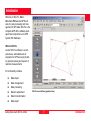
1
20 30 40 50 GPS System 500 User Manual / Getting Started with SKI-Pro Version 3.0 English SKI-Pro GPS Software Congratulations on your purchase of Leica SKI-Pro Software In order to use this software correctly and reliably, you must follow the instructions given in this user manual and/ or in the on-line help system. You must also adhere to the directions given in the user manual for the product with which you are using the software. The rights and responsibilities accruing in respect to Leica as a result of acquisition of the software are set out in the Leica Software Licence Agreement. All of the instructions and directions required for technical specialist to use the software are included in this user manual, which is only available in certain languages. Preface 2 Getting Started with SKI-Pro-3.0.0en Product Identification Technical Support The software version of your copy of SKI-Pro is written on the CD-ROM label. The License Number is given on the SKI-Pro Software Licence Agreement. Enter the software version and licence number in the spaces provided below and always refer to this information when you need to contact agency or authorized service workshop. Technical Support is provided by Leica Geosystems worldwide network of representatives. We are represented in almost every country in the world. A representative directory is available at: Software Version: www.leica-geosystems.com Language: Licence Number: Getting Started with SKI-Pro-3.0.0en 3 Preface Symbols used in this manual Important paragraphs which must be adhered to in practice as they enable the product to be used in a technically correct and efficient manner. Preface 4 Getting Started with SKI-Pro-3.0.0en Chapter Overview Getting Started with SKI-Pro-3.0.0en Introduction 7 Installation 10 An Overview of SKI-Pro 14 Quick Tour I - Real Time 28 Quick Tour II - Post Processing 39 Quick Tour III - Format Manager 64 Quick Tour IV - GIS/CAD Export 69 5 Chapter Overview Contents Introduction ................................................... 7 Licence Agreement and Support ............................... 8 Software Protection .................................................... 8 Installation ................................................... 10 Installation Instruction ...............................................11 Uninstall SKI-Pro ...................................................... 12 Starting and exiting SKI-Pro ..................................... 13 An Overview of SKI-Pro .............................. 14 SKI-Pro components ................................................ 14 Software Navigation Tools ....................................... 21 Views ........................................................................ 23 Accessing the On-line Help ..................................... 26 Quick Tour I - Real Time.............................. 28 Lesson One - Starting a Project and Importing Raw Data ................................................................. 29 Lesson Two – Exploring the View/Edit Component . 34 Lesson Three - Exporting Coordinates to a Custom ASCII File .................................................... 36 Contents 6 Quick Tour II - Post-Processing ................. 39 Lesson One - Starting a Project and Importing Raw Data ................................................................. Lesson Two - Processing Baselines ........................ Lesson Three - Creating a Coordinate System ....... Lesson Four - Importing an ASCII File ..................... Lesson Five - Calculating Transformation Parameters .............................................................. Lesson Six - Using a Coordinate System with a Project ...................................................................... Lesson Seven - Exporting Coordinates to an ASCII File ................................................................. 40 43 50 52 56 59 61 Quick Tour III - Format Manager................. 64 Lesson One - Creating a Format Template File ....... 64 Lesson Two - Uploading a Format Template File to the Sensor ............................................................ 68 Quick Tour IV - GIS/CAD Export ................. 69 Getting Started with SKI-Pro-3.0.0en Introduction Welcome to SKI-Pro, StaticKInematic-Professional GPS software for post-processing and management of GPS data. SKI-Pro is the complete GPS office software package that accompanies Leica GPS System 500 Hardware. What is SKI-Pro Leica’s SKI-Pro software is a comprehensive, automated suite of programs for GPS surveying including post-processing and support of real-time measurements. It’s functionality includes: Data import Data management Data processing Network adjustment Datum transformation Data export Getting Started with SKI-Pro-3.0.0en SKI-Pro user interface (graphical view) 7 Introduction Licence Agreement and Support Software Protection Read the Software License agreement carefully before opening the package containing the installation CD-ROM. Part of SKI-Pro is not protected and may be used without the software protection key (dongle). The unprotected part contains: • • • • • • • • • • • • Introduction 8 Satellite Availability Data Import RINEX Export ASCII Import / Export Project Management Coordinate Set Management Coordinate System Management View and Edit Codelist Management Antenna Management Data Exchange Manager Software Upload Getting Started with SKI-Pro-3.0.0en Software Protection, continued The protected options are available individually and can be accessed by using the software protection key only. The protected options are: • • • • • GPS-Processing Datum and Map Adjustment RINEX Import GIS / CAD Export If you are installing SKI-Pro all options will be installed automatically but the protected options are accessible only if the software protection key is connected to the parallel port of the computer and if the purchased options have been activated on the protection key. Getting Started with SKI-Pro-3.0.0en 9 Introduction Installation Installing SKI-Pro is a simple process. This brief chapter explains everything you need to know regarding installation. System requirements: The computer and system software you intend to use with SKI-Pro must meet the following minimum requirements. Note that SKI-Pro works best with the recommended requirements. The operating system must be one of the following: Windows 98, Windows 2000, Windows NT 4.0 (or later), Windows ME or Windows XP. Internet Explorer 4.0 or higher is required. • • • • PC with Pentium processor 133 Mhz 32 MB RAM 100 MB free space on harddisk (for typical installation) RS232 COM port Parallel Port (for software protection key) CD-ROM drive Mouse installed Installation • • • • • • • PC with Pentium processor 500 Mhz or faster 128 MB RAM 300 MB free space on harddisk RS232 COM port Parallel Port (for software protection key) CD-ROM drive Mouse installed Before you install: Ensure that your computer and software conform to at least the minimum requirements as outlined above. SKI-Pro requires at least 100 MB of free disk space. The programs on the installation CD are compressed and will be expanded during installation. Minimum Hardware requirements: • • • Recommended Hardware requirements: Under Windows 2000 or Windows XP SKI-Pro can only be installed successfully if the user is logged in as Administrator. 10 Getting Started with SKI-Pro-3.0.0en Installation Instruction SKI-Pro is delivered on a CD-ROM. If you do not have a CD-ROM drive you can order the installation on floppy diskettes separately. To install SKI-Pro from CD-ROM: ¾Insert the CD-ROM labelled “GPS System 500SW”. The install shield will start automatically and guide you through the installation process. During the installation you are given the following option to install: Typical or Compact. If you choose Typical all components including the optional components will be installed. This option is recommended in most cases. Choose Compact only if you are always using SKI-Pro without the software protection key (dongle) and want to save diskspace. Getting Started with SKI-Pro-3.0.0en 11 Older version of SKI-Pro already installed If you have an older version of SKI-Pro already installed on your computer all database information such as Projects, Coordinates Sets and Coordinate Systems will be updated automatically. Database information from SKI 2.3 or earlier will NOT be updated automatically. To update SKI 2.3 (or earlier) Projects you can either reimport raw data and process them again or you can import final coordinates or baselines via SKI ASCII files. Installation Uninstall SKI-Pro Do not delete any program files manually by using Windows Explorer or any other File Management program. To delete the SKI-Pro installation on your computer follow the instruction below: ¾From the WindowsTM Start bar, click Programs. ¾Select SKI-Pro. ¾Click Uninstall Leica SKI-Pro. ¾Confirm with Yes. All SKI-Pro files and settings will be removed permanently from the harddisk. Installation 12 Getting Started with SKI-Pro-3.0.0en Starting and exiting SKI-Pro To start SKI-Pro: To exit SKI-Pro: ¾ Ensure that the green software protection key (dongle) is inserted into the parallel port of your computer. ¾From the File menu click Exit or click on the the SKI-Pro main window. icon of ¾From the WindowsTM Start bar, click Programs. ¾Select SKI-Pro. ¾Click SKI-Pro. Under Windows 2000 or Windows XP SKI-Pro can only be started successfully if the user belongs to the Administrator or Power User group. Getting Started with SKI-Pro-3.0.0en 13 Installation An Overview of SKI-Pro SKI-Pro components SKI-Pro runs on 32-bit Microsoft® WindowsTM 98, 2000, NT, ME or XP platforms. As SKI-Pro software is based on an intuitive graphical interface with standard WindowsTM operating procedures, it is remarkably easy to learn and use. All components have a uniform appearance and interact instantly and seamlessly with each other in a multi-tasking software environment. Those who are already familiar with WindowsTM will find SKI-Pro very easy to handle. Those with no prior knowledge of WindowsTM will find it quick and easy to learn. SKI-Pro consist of several components: • • • • • • • • • • • • • • • • Project Management Coordinate Set Management Coordinate System Management Antenna Management Codelist Management Data Exchange Manager Software Upload Raw Data Import ASCII Import ASCII Export RINEX Export GIS/CAD Export* Datum and Map* GPS-Processing* Adjustment* RINEX Import* *Some of these components are delivered as options which gives the user the opportunity to select the combination which best suits his or her needs and budget. Refer to chapter 1.2 Software Protection for more information. An Overview of SKI-Pro 14 Getting Started with SKI-Pro-3.0.0en SKI-Pro components, continued The following external programs cannot be accessed from within SKI-Pro but are installed automatically with SKI-Pro: • • • Project Management All GPS data that is collected and that belongs together can be organized in SKI-Pro within a single Project. This Project could contain, for example, all data relating to a particular contract you are carrying out for a client. Satellite Availability Road Line Editor Format Manager These programs are not explained in this manual. Please refer to the corresponding Manuals or Help Systems of the programs for more information. In the Project Management you can create, open, and edit projects as well as register projects not contained in the project list. The Project Management can also be used to attach and modify Coordinate Systems. Never delete a project or any of the files contained within a project from outside SKIPro. Always use the Project Management to delete unwanted projects. Deletion of projects or project files from outside of SKI-Pro can result in the destruction of the consistency of the database, which will lead to unrecoverable database errors. Getting Started with SKI-Pro-3.0.0en 15 An Overview of SKI-Pro SKI-Pro components, continued Coordinate Set Management Coordinate System Management The Coordinate Set Management manages Coordinate Sets that are stored in the SKI-Pro database. A Coordinate Set is a list of point coordinates that are stored independently from Projects. A Coordinate System may be assigned to a Coordinate Set, allowing you to switch between Cartesian, Geodetic and Grid coordinates. Points can be added either manually, by importing via ASCII file or by dragging from an existing Project. A Coordinate Set can either hold WGS84 or Local Coordinates but does not allow to switch between them. An Overview of SKI-Pro A coordinate system provides the information necessary to convert coordinates to different representations (Cartesian, Geodetic or Grid) and to transform coordinates between the WGS84 and the Local System. A Coordinate System may be attached to a Coordinate Set or to a Project. Within SKI-Pro the user can work in the global system (WGS84) or in a local coordinate system. The local coordinate system may be a geodetically defined system or it may be a simple grid system with neither an ellipsoid nor a projection associated with it. The Coordinate System Management is linked to a database that stores the parameters. This database is independent from the project database. 16 Getting Started with SKI-Pro-3.0.0en SKI-Pro components, continued Data Exchange Manager Antenna Management The Antenna Management allows you to define and edit parameters for different GPS antennas. This information is stored in a global database and can be used to upload to the Sensor or in a Project for GPS-Processing. All Leica antennas are pre-defined upon installing the software and the user is not permitted to make any changes to these pre-defined antennas. The Data Exchange Manager component allows you to transfer data from and to the instrument. Data can be downloaded or uploaded directly onto a PCMCIA card or via serial communication. All SKI-Pro database objects (e.g. Projects, Coordinate Systems etc.) can be transferred and will be converted to the data structure of the instrument if required. Up- and download of single files is also possible. Codelist Management A Codelist contains Thematical or Free Coding information that may be assigned to points during measurement in the field. A Codelist may be attached to a Project. The Codelist Manager enables you to create and edit Codelists for later use in the field. Getting Started with SKI-Pro-3.0.0en 17 Software Upload The Software Upload tool enables you to load Sensor/ System firmware or other software (Terminal firmware, Language files, Configuration files or Character sets) onto the instrument via serial communication. Throughout the software upload procedure you are guided by the Sofware Installation wizard. An Overview of SKI-Pro SKI-Pro components, continued Raw Data Import ASCII Import The Raw Data Import component enables you to import GPS field data into SKI-Pro. It is possible to transfer GPS raw observations for postprocessing along with related point information as well as coordinates recorded in Real-Time into Projects or Coordinate Sets. GPS raw observations may be in Leica System 200, 300 or 500 format. Optionally GPS raw observations may be imported in RINEX format. See also RINEX Import. The ASCII Import component enables you to import coordinates and baselines from pre-defined or userdefined files. You may import pre-defined files of Leica standard format SKI-ASCII or IDEX (InDependent EXchange format). An import wizard allows to define unknown file formats and enables you to import any kind of user-defined coordinate files. It is also possible to import coordinate files in ASCII format into Projects or Coordinate Sets. Additionally, there is the facility to import Precise Ephemeris data. An Overview of SKI-Pro 18 Getting Started with SKI-Pro-3.0.0en SKI-Pro components, continued ASCII Export GIS/CAD Export (optional) The Export component enables you to export data from SKI-Pro. Coordinate information may be exported to ASCII files in various pre-defined or user-defined formats. The GIS/CAD Export is an optional Export tool. It enables you to write the point coordinates to AutoCAD (DXF/ DWG), MicroStation (DGN) or MapInfo (MIF) formatted files. See also GIS/CAD Export option. Datum and Map (optional) RINEX Export The RINEX Export enables you to export GPS raw observations to an ASCII file in RINEX format. Unlike the RINEX Import this function is not an option and is available as standard. Getting Started with SKI-Pro-3.0.0en 19 If the user requires final coordinate output in the coordinate system to which the GPS measurements are related (WGS84) then this optional tool is not necessary. However, in most cases it is necessary to transform the WGS84 coordinates into a local coordinate system. The Datum and Map option provides you with a tool to determine transformation parameters which can then be used to perform datum transformations within two sets of coordinates. An Overview of SKI-Pro SKI-Pro components, continued GPS-Processing (optional) Adjustment (optional) The GPS-Processing is an option that can be accessed via the GPS-proc Tab from within a Project window. It allows you to process GPS observations that have been recorded in the field to achieve WGS84 coordinates and their relative accuracy. Static, Rapid-Static, Stop and Go, Kinematic, Kinematic on the Fly, and Single-Point data can be processed. Adjustment is an option that can be accessed via the Adjustment Tab from within a Project window. It provides you with a powerful tool for performing a least squares adjustment on a network of baseline vectors and terrestrial data (directions, distances, vertical angles, azimuths and height differences). Additionally it enables you to perform a network simulation based upon default observation precisions to find out how good the design of your network is before you measure. The data to be processed may be selected graphically. The computation itself is completely hidden for the user. All selected data is processed automatically in a batch process without the need for any user interaction. After the GPS-Processing is completed the results can be viewed and stored for further use in the Results-View. A graphical user interface similar to that of View/Edit allows you to select the points and observations to be adjusted. RINEX Import (optional) RINEX Import is the optional part of the data Import tool. It enables you to import GPS observation data collected with third party receivers in RINEX (Receiver INdependent EXchange) format. An Overview of SKI-Pro 20 Getting Started with SKI-Pro-3.0.0en Software Navigation Tools The various components of SKI-Pro may be accessed using different methods. In order to navigate through the software you may choose the tools which you prefer: Menu Toolbar List Bar Context-Menu Tabbed Views Getting Started with SKI-Pro-3.0.0en 21 An Overview of SKI-Pro Software Navigation Tools, continued Menu Bar Context Menu The Menu Bar is a special Toolbar at the top of the screen that contains menus such as File, Edit and View. The Menu Bar lists the available commands. If a command is not applicable it is greyed out and not accessible. Almost everywhere upon right-click on a particular item in SKI-Pro a Context-Menu is available. A Context-Menu lists all useful commands at a particular instant for a particular item on the screen. It is possible to navigate through the entire software by only using commands from the Context-Menu. Toolbar Toolbars allow you to organize the commands you use most often the way you want to, so you can find and use them quickly. You can easily customize toolbars - for example, you can add and remove buttons, create your own custom toolbars, hide or display toolbars, and move toolbars. Tabbed-View Upon opening a Project, tabs at the bottom of the view allow you to quickly switch from one view to another. You may instantly switch from, for example, a Graphical View (View/Edit) to the Points View or GPS-processing View. List Bar The List Bar gives you single-click access to all available components and tools of SKI-Pro. Additionally if a Project or a Coordinate Set is open it lists them. Therefore the List Bar allows you to simply switch between a tool and/or a Project or Coordinate Set. You can display small or large icons or hide the List Bar. The List Bar is divided into groups (folders) to help organize your information. Click a folder, e.g. Management, to move to a different set of tasks. An Overview of SKI-Pro 22 Getting Started with SKI-Pro-3.0.0en Views Explorer-View Tree-View Throughout SKI-Pro a powerful Explorer-View is utilized to list information, be it database information or results from calculations. This view which has similar functionality as the WindowsTM Explorer view normally consists of two panes. A Tree-View on the left-hand side and a Report-View or Property-View to the right hand side. Listed data may be easily arranged, sorted, selected and even printed. The Tree-View pane provides you with an overview of the items you are currently working with, in an expandable/collapsible hierarchy of folders and pages . Double-click on a folder or click expand (open) it. to Tree-View If a folder is open double-click on it or click (close) it. to collapse Click on a folder or page to display the content of it. Depending on the type of data to be displayed the data will be listed in a Report-View or Property-View. Explorer-View Getting Started with SKI-Pro-3.0.0en 23 An Overview of SKI-Pro Views, continued Report-View Property-View Database information such as e.g. Points or Observations may be listed in a Report View. Database information such as e.g. Project Properties may be listed in a Property-View: Report-View The data records are listed in rows and columns. Each row displays one record. The columns are fully user configurable. You can change the width, sort the records according to columns or view and hide individuals columns. Certain data items may be modified by simply doubleclick on them. Property-View The information is listed in two colums. The first column lists the description (Property) and the second column lists the actual value. Property-Views are not user configurable. An Overview of SKI-Pro 24 Getting Started with SKI-Pro-3.0.0en Views, continued Graphical-View The data contained within a Project may not only be viewed and edited using the Report-View but also using a graphical user interface. Two types of Graphical-Views may be utilised. Points and Baselines are displayed in a map-view while observation data is displayed in a combined Report /Graphical-View. Both views enable you to select and modify data, zoom in, zoom out and even print the view. Graphical-View of View/Edit or Adjustment Graphical-View of GPS-Processing Getting Started with SKI-Pro-3.0.0en 25 To switch between the different views of a Project simply click on the tabs below the view. An Overview of SKI-Pro Accessing the On-line Help The SKI-Pro On-line Help System is a very comprehensive reference and includes all the detailed information about the whole software package. To display the On-line Help System: ¾From the Help menu click Contents and Index. The Help Topics property sheet appears: Any Information NOT contained in this user manual can be found in the On-line Help System. All topics contained in the Help are listed in books pages . ¾Double-click on a book An Overview of SKI-Pro 26 to open it and . Getting Started with SKI-Pro-3.0.0en Accessing the On-line Help, continued A book may contain pages ¾Click on a page or other books What’s this Help: . Help topics may also be accessed via the controls and commands from the SKI-Pro user interface: to open the help text. ¾Click the icon from the Toolbar and click on another Toolbar or List Bar icon or select a command from the menu to open the appropriate help topics. To find a topic in the Help: ¾Click the Contents tab to browse through topics by category. Alternatively select “What’s This?” from the Help menu or press F1 to get help on the currently active component. ¾or click the Index tab to see a list of index entries: either type the word you're looking for or scroll through the list. Glossary of terms: ¾or click the Search tab to search for words or phrases that may be contained in a Help topic. ¾or click the Favorites tab to quickly display a topic that you have collected in your personal list of frequently opened topics . If you do not understand a particular term used in the software refer to the Glossary of terms contained in the On-line Help System. ¾If the Contents tab isn't already displayed, click on Contents. To print Help text: ¾Double-click the Getting Help book. ¾If the Contents tab isn't already displayed, click on Contents. ¾Click the Glossary of Terms page and click on the desired term in the list. ¾Select the book or the page that you want to print. For more information on the Help System refer to the Getting Help chapter (book) in SKI-Pro’s On-line Help. ¾Click on the Print button. ¾Make sure the printer information is correct. ¾Select OK to confirm. Getting Started with SKI-Pro-3.0.0en 27 An Overview of SKI-Pro Quick Tour I - Real Time This Quick Tour is a step-by-step tutorial in which you learn how to work with real time GPS data. When using real time the processing and the applying of coordinate systems is already done in the field, so that the office work is reduced to importing raw data, eventually checking the results and directly exporting the final grid coordinates. This Quick Tour comprises of the following steps: Lesson One Importing GPS raw data and the attached coordinate system Creating the RealTime Fieldbook report Creating a Project This exercise does NOT need your green software protection dongle to be connected. Lesson Two Exploring the View/Edit component The exercise comprises of the following scenario: Lesson Three Exporting coordinates to a customized ASCII file A number of real time points have been measured. Two different reference stations have been used. The points BM1 to BM4 have been measured from both reference stations, all other points from either reference station TP306 or from reference station B215. The raw data is given in the directory: ...\SkiPro\Data\SampleData\Sys500\Realtime. A local coordinate system has been used in the field, which comprises of a UTM Zone 32 North Projection on the Bessel Ellipsoid and a Classical 3D Transformation called “Sample WGS-Bess“. Quick Tour I - Real Time 28 Getting Started with SKI-Pro-3.0.0en Lesson One - Starting a Project and Importing Raw Data In Lesson One you will learn how to import GPS raw data and at the same time create a new Project. Start-up SKI-Pro: ¾From the Start menu select Programs, SKI-Pro and then click on SKI-Pro. The main SKI-Pro window appears. Getting Started with SKI-Pro-3.0.0en 29 ¾From the Import menu or Toolbar select GPS Raw Data . or ¾from the Tools List Bar select Import GPS Raw Data Quick Tour I - Real Time Lesson One - Starting a Project and Importing Raw Data, continued The following Property Sheet appears: The following dialog appears: ¾Under Files of type: select GPS500 raw data. ¾Under Look in: select the directory that contains the sample data: ...\SkiPro\Data\SampleData\Sys500\Realtime\Data\Geodb Depending where you installed SKI-Pro the path for the sample data may vary slightly. By default SKI-Pro will be installed in: C:\Program Files\Leica Geosystems\... This is where you can view and modify the raw data. If you have not yet created any Project, the list of Projects is empty and you can not select an existing Project. ¾Right-click on Projects and select New. ¾From the browser select the job RT-Sample ¾Click Import. Quick Tour I - Real Time 30 Getting Started with SKI-Pro-3.0.0en Lesson One - Starting a Project and Importing Raw Data, continued ¾Enter a Project Name e.g. RT Sample. Note that the directory RT Sample has been added automatically to the path. This is necessary because a Project consists of several files and each Project shall be stored under a separate directory. The following dialog appears and allows you to create a new project while you are still in the Import (Assign) procedure: ¾Click OK to confirm. The New Project Dialog will be closed and a new Project will be created and selected automatically. Alternatively you can also create a Project using the New Project command from the File menu or Toolbar or via the Project Management of the List Bar. ¾Under Location enter a path e.g C:\SKIPro\Data\Projects Alternatively you may use the browser. Getting Started with SKI-Pro-3.0.0en 31 Quick Tour I - Real Time Lesson One - Starting a Project and Importing Raw Data, continued ¾Back in the Assign dialogue click the Settings tab. Alternatively you can also attach any other coordinate system to the project later. ¾Click the Fieldbook tab to create a fieldbook report. Here you can select the coordinate system, that has been used in the field to be imported into the SKI-Pro Coordinate System Management. Additionally the Coordinate System will be automatically attached to the project to which you assign the data. ¾Make sure both options are checked as indicated above. Quick Tour I - Real Time ¾Select Coordinate Type Local and Grid as shown above. ¾Click Preview… to view the report. 32 Getting Started with SKI-Pro-3.0.0en Lesson One - Starting a Project and Importing Raw Data, continued A GPS Fieldbook Report will be generated and shown in a Report View: The GPS Fieldbook Report displays the details of the survey completed in the field. To scroll through the report use the toolbar buttons and . or press Ctrl PgDown and Ctrl PgUp. To print the report click on . ¾To close the Report View click the upper right corner. in ¾Click the General tab to return to the General page of the Assign dialog ¾Select Assign and then Close. The Project window will open automatically and display the surveyed points in the local grid coordinate system. Continue with Lesson Two – Exploring the View/ Edit component. Getting Started with SKI-Pro-3.0.0en 33 Quick Tour I - Real Time Lesson Two – Exploring the View/Edit Component In Lesson Two you will learn some useful features of the View Edit component. The View/Edit project window opens directly in local grid zooming to the full extents including the reference stations. To get a clearer view you may additionally want to switch off the GPS baseline vectors (the red lines) and switch on the grid lines and the chains (yellow lines) showing how the survey was performed. ¾Right-click on the background select Graphical Settings and change the settings as shown below. Refer to the Online Help for more information about the other graphical settings. ¾Use the toolbar button to zoom into the detail points. Quick Tour I - Real Time 34 Getting Started with SKI-Pro-3.0.0en Lesson Two – Exploring the View/Edit Component, continued The display should now look as follows: If the point is not within the zooming extents, you can use the scroll-to point combobox and the Edit Point toolbar button. ¾Click the Mean tab in the property sheet. The following Property page displays the two solutions and their differences to the weighted average: The Point symbols indicate, that the point class is already Measured, as the points were measured in real time in the field. For some points (e.g. BM1) the point symbol indicates, that the point class is Averaged, because these points have been occupied twice. For these two solutions a weighted average is automatically computed. ¾Drag the horizontal scroll bar to the right to display more information. ¾Right-click on point BM1 and select Properties. Alternatively you can also double-click on the point symbol. ¾Click OK or Cancel to exit the property sheet. Getting Started with SKI-Pro-3.0.0en 35 Quick Tour I - Real Time Lesson Three - Exporting Coordinates to a Custom ASCII File In this Lesson you will learn how to Export coordinates to a customized ASCII file. The Custom ASCII File export type is using a pre-defined format template file (*.frt) to export the data. Format template files can be created using the Leica Format Manager program. To complete this exercise a sample format template file (sample.frt) is installed automatically on your computer with SKI-Pro. However If you whish to create your own format template file please refer to Quick Tour III - Format Manager. The following dialog appears: You can export coordinates in a variety of other pre-defined formats. Please refer to the On-line Help on Export ASCII and Export GIS/ CAD for more information. ¾Under Save in select a path. ¾Under Save as type select Custom ASCII File. While the Project is still open: ¾From the Export menu select ASCII, or ¾from the Tools List Bar or Toolbar select Export ASCII Data . Quick Tour I - Real Time 36 ¾Enter a File name e.g. RT Sample1 without extension. ¾Click on the Settings button to change the settings and select the format template file. Getting Started with SKI-Pro-3.0.0en Lesson Three - Exporting Coordinates to a Custom ASCII File, continued ¾To continue, click on the Coordinate System tab. The following Property page appears: ¾Make sure the Coordinate System Sample RT is selected. By default the coordinate system attached to the current project is already selected. ¾Click on OK to close the Settings property page, and finally, ¾Click Save to write the file to the harddisk. ¾Change Coord. Class to Main. The coordinate triplets of the highest class will be exported. ¾ Use the browser to select the file …\Shared\Templates\Format Manager\Sample.frt. Depending where you installed SKI-Pro the path for the sample file may vary slightly. By default SKI-Pro will be installed in: C:\Program Files\Leica Geosystems\... Getting Started with SKI-Pro-3.0.0en 37 Quick Tour I - Real Time Lesson Three - Exporting Coordinates to a Custom ASCII File, continued If you open the ASCII file with a Text Editor it will display the following information: Congratulations ! You have successfully completed this Quick Tour. You have learnt how to create a Project, Import GPS real time data including the attached coordinate system, check the data in View/Edit and finally how to export these coordinates to a customized ASCII file. Quick Tour I - Real Time 38 Getting Started with SKI-Pro-3.0.0en Quick Tour II - Post-Processing This Quick Tour is a step-by-step tutorial in which you learn to post-process GPS data from importing raw data to exporting final local Grid coordinates. This Quick Tour comprises of the following steps: This exercise assumes that your green software protection dongle is connected and the two options GPS-processing and Datum and Map are activated. Lesson One Importing GPS raw data Creating a Project Lesson Two Modifying reference coordinates Processing baselines Lesson Three Creating a Coordinate System The exercise comprises of the following scenario: A rapid static network has been measured. It consists of the points TP214, B215, TP306, B218 and B313. The whole network has been measured with two receivers only. The raw data is given in the directories: Lesson Four Importing an ASCII file with local coordinates Lesson Five Calculating Transformation Parameters ...\SkiPro\Data\SampleData\Sys500\Static\data1 ...\SkiPro\Data\SampleData\Sys500\Static\data2. The local coordinates of the points B215, B218, B313 are known in UTM Zone 32 North Projection and Bessel Ellipsoid. The coordinates are given in the file: ...\SkiPro\Data\SampleData\Static\Local.txt Lesson Six Using a Coordinate System with a Project Lesson Seven Exporting Coordinates to an ASCII file The local grid coordinates of the points TP214 and TP306 shall be derived. Getting Started with SKI-Pro-3.0.0en 39 Quick Tour II - Post-Processing Lesson One - Starting a Project and Importing Raw Data In Lesson One you will learn how to import GPS raw data and at the same time create a new Project. ¾From the Import menu or Toolbar select Start-up SKI-Pro: GPS Raw Data . or ¾from the Tools List Bar select Import GPS Raw Data. ¾From the Start menu select Programs, SKI-Pro and then click on SKI-Pro. The main SKI-Pro window appears. Quick Tour II - Post-Processing 40 Getting Started with SKI-Pro-3.0.0en Lesson One - Starting a Project and Importing Raw Data, continued The following dialog appears: The following Property Sheet appears: ¾Under Files of type: select GPS500 raw data. ¾Under Look in: select the directory that contains the sample data: ...\SkiPro\Data\SampleData\Sys500\Static ¾Check Include subfolders: all GPS500 raw data in the two sub-directories data1 and data2 will be imported in one run. Depending where you installed SKI-Pro the path for the sample data may vary slightly. By default SKI-Pro will be installed in: C:\Program Files\Leica Geosystems\... This is where you can view and modify the raw data. e.g. to change instrument heights or point id’s. As you have not yet created a Project the list of Projects is empty and you can not select an existing Project. ¾Right-click on Projects and select New. ¾Click Import. Getting Started with SKI-Pro-3.0.0en 41 Quick Tour II - Post-Processing Lesson One - Starting a Project and Importing Raw Data, continued ¾Enter a Project Name e.g. PP Sample. Note that the directory PP Sample has been added automatically to the path. This is necessary because a Project consists of several files and each Project shall be stored under a separate directory. The following dialog appears and allows you to create a new project while you are still in the Import (Assign) procedure: ¾Click OK to confirm. The New Project Dialog will be closed and a new Project will be created and selected automatically. Alternatively you can also create a Project using the New Project command from the File menu or Toolbar or via the Project Management of the List Bar . ¾Back in the Assign dialog select Assign and then Close. The Project window will open automatically. ¾Under Location enter a path e.g C:\SKIPro\Data\Projects Alternatively you may use the browser Quick Tour II - Post-Processing Continue with Lesson Two - Processing Baselines. . 42 Getting Started with SKI-Pro-3.0.0en Lesson Two - Processing Baselines In Lesson Two you will learn how to process and store baselines. The Project window allows you to display the content of a Project by using different tabbed views. Click on the tabs below the window to switch between the different views. Please refer to the on-line help on how to perform a Single Point Processing. In our case we will start the survey on a known point and therefore have to modify the coordinates of our first reference point. ¾Right-click on point B215 and select Properties. View/Edit shows a graphical representation of each point of the Project. The Point Symbols indicate that the point class is still Navigated . I.e. the accuracy of the points is low (±100m). In order to avoid that the results of the baselines are influenced by systematic errors, the coordinates of the first reference point in the network have to be known within about 20m in the WGS84 coordinate system. This can be achieved by starting the GPS survey on a point with known WGS84 coordinate or by using a Single Point Processing for the starting point of the network. Getting Started with SKI-Pro-3.0.0en 43 Quick Tour II - Post-Processing Lesson Two - Processing Baselines, continued The Point Property Sheet appears: You are now ready to switch to the GPS-Processing View and select the baselines to be processed. ¾Click the GPS-proc tab at the bottom of the window. The following View displays a list of all observation intervals and a graphical representation of the observation time for each interval: ¾Change the Point Class to Control. ¾Change the Coordinates to the values below: Latitude: 47° 23’ 45.92367 N Longitude: 9° 38’ 10.58353 E Height: 429.279 m ¾Click OK to confirm. The Point Symbol of point B215 indicates that the point class is now Control. Quick Tour II - Post-Processing 44 Getting Started with SKI-Pro-3.0.0en Lesson Two - Processing Baselines, continued A Baseline is always processed between a Reference point and a Rover point. In the graphical window all observations are represented by horizontal bars which you can select as Reference or Rover. To select the Reference point: ¾Right-click the on horizontal bar of point B215 and select Reference. In our network the point B215 was first used as a Reference and the points TP214, TP306, B313 and B218 have been observed as Rover points. The colour of the Reference interval changes to Red. We are now ready to start the first processing run and process four baselines. ¾Right-click on the background and select Process or ¾click on Process from the Toolbar. Afterwards point B218 was used as the Reference and the points TP214, B215 and B313 were observed as Rover. Finally point B313 was the Reference and TP306 was the Rover. Therefore to process all baselines we have to make three processing runs. A progress indicator will be displayed and the number below indicates which baseline out of the total number is currently being processed. ¾Right-click on the background of the graphical window, click on Select Mode and then Rover. -or¾click on Select Mode: Rover from the Toolbar. The cursor indicates Rover. ¾Click on the horizontal bars of the first instant of point TP214, TP306, B313 and B218. The colour of the Rover intervals changes to Green. Getting Started with SKI-Pro-3.0.0en 45 Quick Tour II - Post-Processing Lesson Two - Processing Baselines, continued After the processing run is completed the display will automatically switch to the Results-View allowing you to examine and store the processed baselines: What does Ambiguity Status mean? The Ambiguity Status is an essential indicator if you want to achieve centimetre level accuracy with short observation times (Rapid Static). Ambiguity Status yes indicates that the determination of the integer number of cycles between the satellites and the GPS receiver was successful, i.e. the baseline calculation is correct. Ambiguity Status no indicates that the ambiguities could not be resolved. Ambiguity Status ? indicates that no attempt has been made to resolve the ambiguites. All Rover points are listed together with its coordinates, quality and the Ambiguity Status. The points for which the Ambiguity Status is yes are selected automatically. If the Ambiguity Status is no or ? you may further analyse the data by viewing the GPS-processing Report. Please refer to the On-line Help for more information on the Report. By default, ambiguities can only be resolved for baselines up to 80 km. For longer distances the ambiguity resolution becomes unreliable. To achieve good results on baselines longer than 80 km you will need to observe for longer periods of time. Quick Tour II - Post-Processing 46 Getting Started with SKI-Pro-3.0.0en Lesson Two - Processing Baselines, continued In our case the Ambiguity Status is Yes for all points (baselines) and we can store the coordinates to the database. To complete the network we have to process the remaining two processing runs. ¾To return to the GPS-Processing View click the GPS-proc tab. ¾Right-click on the selected points and select Store or use the toolbar . ¾Right-click on the background and click on Deselect All. The results of the four baselines are now stored in the database. ¾Select the second instant of the points TP214, B215, B313 as Rover and the point B218 as Reference. ¾To verify that the baselines have been stored, click the View/Edit tab at the bottom of the window. ¾Process and Store the second run. ¾Right-click in the background and select Graphical Settings... Make sure GPS is checked. The following view is displayed: The following view is displayed: Getting Started with SKI-Pro-3.0.0en ¾Finally, Select, Process and Store the remaining baseline between B313 and TP306. 47 Quick Tour II - Post-Processing Lesson Two - Processing Baselines, continued In View/Edit you will notice that the point symbols have now changed for all points. The point classes are no longer Navigated. Points that have been used as reference points are now awarded the point class Reference . Others have point class Measured or, if they have been measured from two different reference stations, class Averaged . The following Property Sheet displays the two solutions and their differences to the weighted average: In a project database there may exist many coordinate triplets for any one point. The coordinate classes represent the hierarchical order of a coordinate triplet. SKI-Pro always displays the coordinate triplet with the highest class for each point as default. For a complete list of all Coordinate Classes refer to the On-line Help. The points TP214 and TP306 consist of two coordinate triplets of class Measured . From these two coordinate triplets a weighted average is calculated automatically and a new coordinate triplet of class Averaged is displayed. ¾Right-click on point TP214 and select Properties. Click the Mean tab on the top of the Property Sheet. Quick Tour II - Post-Processing 48 ¾Drag the horizontal scroll bar to the right to display more information. ¾Click OK or Cancel to exit the Property Sheet. Getting Started with SKI-Pro-3.0.0en Lesson Two - Processing Baselines, continued To display all point information in a Report-View: To display and hide information: ¾Click the Points tab at the bottom of the window. ¾Right-click on a column header and select Hide. The following view is displayed: ¾Right-click on any column header, select View and select the required item from the list. To print the content of the Report-View: ¾From the File menu or Toolbar select Print . The print function can be accessed from any view, be it a Graphical-View or a Report-View. You have now finished the data processing. Five points in the WGS84 coordinate system with centimetre accuracy are now available. To change the width of a column: ¾Drag the right side of a column header as required. or ¾Right-click on any column header and select Auto arrange. All columns will be arranged automatically. ¾From the Window menu select Close or click the lower icon in the top right corner. To sort the list: ¾Click on a column header. The records will be sorted in ascending or descending order according to the selected column. Getting Started with SKI-Pro-3.0.0en 49 Continue with Lesson Three - Creating a Coordinate System. Quick Tour II - Post-Processing Lesson Three - Creating a Coordinate System The following Explorer-View appears: In this Lesson you will learn how to create a Coordinate System. A Coordinate System defines the parameters used to calculate different coordinate representations. If a Coordinate System is attached to a Project or a Coordinate Set it enables you to switch between displaying the coordinates in Cartesian (X,Y,Z), Geodetic (Latitude, Longitude, Height) or Grid (Easting, Northing, Height) format. Additionally if a Transformation is defined you can switch the coordinates of a Project between the WGS84 and a local datum. What we already know of our Coordinate System is that the local Ellipsoid is Bessel and the Map Projection is UTM32 North. The Transformation is not yet known and has to be determined by using the Datum/Map tool first. First you have to define the Map Projection: ¾In the Tree-View right-click on Projection and select New. The following Property page appears: To open the Coordinate System Management: ¾From the Tools menu or Management List Bar, select Coordinate System Management. ¾Fill in the Property page as above. ¾Click OK to confirm. Quick Tour II - Post-Processing 50 Getting Started with SKI-Pro-3.0.0en Lesson Three - Creating a Coordinate System, continued ¾In the Tree-View right-click on Coordinate Systems and select New. The following Property page appears: ¾Fill in the Property page as above. ¾Click OK to confirm. ¾From the Window menu select Close or click the lower icon in the top right corner to close the Coordinate System Management. Getting Started with SKI-Pro-3.0.0en 51 Quick Tour II - Post-Processing Lesson Four - Importing an ASCII File In this Lesson you will learn how to import the local control points from a user defined ASCII file and create a Coordinate Set. ¾From the Import menu click ASCII data. or ¾from the Tools List Bar click Import ASCII Data ¾Under Coordinate System select Local. ¾Click Import. This is the first time you are importing an ASCII file of this type. The import Wizard for user defined ASCII files appears automatically, allowing you to define the file format: The following dialog appears: ¾Choose the file type Text files. The file to be imported is a simple ASCII file. The local coordinates of the points B215, B218 and B313 are separated with spaces and neither a column header nor a keyword is defined. ¾Under Look in select the directory that also contains the sample data: ...\SkiPro\Data\SampleData\Sys500\Static ¾Select the file Local.txt Quick Tour II - Post-Processing ¾Click Free and then Next to continue. 52 Getting Started with SKI-Pro-3.0.0en Lesson Four - Importing an ASCII File, continued The Wizard Step 2 appears: The Wizard Step 3 appears: ¾Check Space, the columns will be selected automatically. ¾Right-click on the first column heading (0) and select Point Id ¾Click Next to continue. ¾Right-click on the second column heading (1) and select Coordinates and then Easting. ¾Select Northing and Ell. Height for the third (2) and fourth (3) column respectively. ¾Click on Next to continue. Getting Started with SKI-Pro-3.0.0en 53 Quick Tour II - Post-Processing Lesson Four - Importing an ASCII File, continued The Wizard Step 4 appears: You can now assign the points to either a Project or a Coordinate Set. Since these are our control points for the determination of the transformation parameters we will assign them to a Coordinate Set. ¾Right-click on Coordinate Sets and select New. The following Property-Sheet appears: ¾Click on Finish to close the Wizard. If you want to import coordinate files of the same type again you can enter a Mask Name and then use this Mask as a Template the next time you import an ASCII file. ¾Enter the Coordinate Set Name e.g. PP Sample local. ¾Select the Coordinate System PP Sample from the list. ¾Click on OK to confirm. Quick Tour II - Post-Processing 54 Getting Started with SKI-Pro-3.0.0en Lesson Four - Importing an ASCII File, continued The Coordinate Set is created and selected automatically: ¾Click on Assign and then Close. The Coordinate Set will open automatically and display the local coordinates for the points B215, B218 and B313. ¾From the Window menu select Close or click the lower icon in the top right corner. Getting Started with SKI-Pro-3.0.0en 55 Quick Tour II - Post-Processing Lesson Five - Calculating Transformation Parameters In this Lesson you will learn how to use the Datum/Map tool to calculate the transformation parameters. The following view appears: In order to be able to calculate Transformation parameters we need two sets of coordinates. The first set will be the coordinates of our Project PP Sample in the WGS84 coordinate system. The second set will be the imported local coordinates from the Coordinate Set PP Sample local. ¾From the Tools menu click Datum/Map. or ¾from the Tools List Bar or Toolbar click Datum and Map. ¾In the upper Tree-View open the Projects folder and select PP Sample. ¾In the lower Tree-View open the Coordinate Sets folder and select PP Sample local. ¾Click on the Match tab to continue. Quick Tour II - Post-Processing 56 Getting Started with SKI-Pro-3.0.0en Lesson Five - Calculating Transformation Parameters, continued The following view appears: The Classical 3D is the transformation type that should normally be used when the local Ellipsoid and the Map Projection is known. However SKIPro supports a variety of different transformation types. Please refer to the On-line Help for more information. You can select the common points of system A and system B by selecting them manually or by using the Auto Match command: ¾Right-click on the background in one of the views and select Auto Match. ¾Click the Results tab to continue. The transformation parameters are instantly calculated. To configure the Transformation type: ¾Right-click on the background in one of the views and . select Configuration or use the Toolbar button ¾Under Transformation select Classical 3D and confirm with OK. Getting Started with SKI-Pro-3.0.0en 57 Quick Tour II - Post-Processing Lesson Five - Calculating Transformation Parameters, continued ¾Enter a name e.g. PP Sample WGS-local, check two boxes and click on OK to confirm. The following view appears and displays the residuals: the By default the names of the new transformation parameter set and the new coordinate system are the same. You may change the name of the coordinate system if you wish. The transformation parameters and the new coordinate system are now stored and the new coordinate system is already attached to the project. Continue with Lesson Six - Using a Coordinate System. This view allows you to judge the quality of the transformation. Additionally you may display a Chart of the residuals or a Report by clicking on the appropriate tabs at the bottom of the window. ¾Right-click on the background and select Store. The following dialog allows you to store the transformation parameters, create a new coordinate system based on the coordinate system of System B and attach it to the project (System A). Quick Tour II - Post-Processing 58 Getting Started with SKI-Pro-3.0.0en Lesson Six - Using a Coordinate System with a Project In this Lesson you will learn how to use a Coordinate System with a Project and switch between WGS84 and local coordinates. Here you can check that the new Coordinate System is attached to the Project and verify the parameters. Ellipsoid: Bessel, Map Projection: UTM 32 North and Transformation: PP Sample WGS-local should now be displayed. If the Project Management is not already open: ¾From the Management List Bar, select Project Management. ¾Click OK to continue. ¾Right-click on the Project PP Sample and select Open. ¾Right-click on the Project PP Sample and select Properties. The Project window opens with the last used View active. ¾Click on the Coordinates tab. ¾Select the Points tab. The following dialog appears: The view displays WGS 1984 coordinates in Geodetic format: Getting Started with SKI-Pro-3.0.0en 59 Quick Tour II - Post-Processing Lesson Six - Using a Coordinate System with a Project, continued Since you are now using a Coordinate System with Ellipsoid, Map Projection and Transformation defined, you are able to switch the Coordinate System to Local and change the Coordinate type to Grid. Using the Coordinate Format Toolbar it is possible to switch between the following different possibilities: • • • • • WGS 1984 Cartesian WGS 1984 Geodetic Local Cartesian Local Geodetic (Bessel Ellipsoid) Local Grid (UTM 32 North Projection) The local grid coordinates of the unknown points TP214 and TP306 are now available. You may now print the list or continue with Lesson Seven - Exporting local coordinates to an ASCII file. ¾From the Toolbar click on Local and then Grid. The view displays Local coordinates in Grid format: Quick Tour II - Post-Processing 60 Getting Started with SKI-Pro-3.0.0en Lesson Seven - Exporting Coordinates to an ASCII File In this Lesson you will learn how to Export coordinates to a user defined ASCII file. The following dialog appears: You can export coordinates to a variety of other pre-defined formats. Please refer to the On-line Help Export ASCII and Export GIS/ CAD for more information. While the Project is still open: ¾From the Export menu select ASCII, or ¾from the Tools List Bar or Toolbar select Export ASCII Data. ¾Under Save in select a path. ¾Under Save as type select Text File. ¾Enter a File name e.g. PP Sample1 without extension. Since you are using this export type for the first time you have to modify the Settings: ¾Click on the Settings button to change the export settings. Getting Started with SKI-Pro-3.0.0en 61 Quick Tour II - Post-Processing Lesson Seven - Exporting Coordinates to an ASCII File, continued The following Property page appears: The following Property page appears: ¾Change Coord Type to Local and Grid. ¾Change Coord. Class to Main. The coordinate triplets of the highest class will be exported. ¾To continue, click on the Point tab. Here you can define the actual point list of the ASCII file. You can select the items to export in the order you want. ¾Double-click on Point Id then Easting, then Northing then Ell. Height. ¾To continue, click on the Coordinate System tab. Quick Tour II - Post-Processing 62 Getting Started with SKI-Pro-3.0.0en Lesson Seven - Exporting Coordinates to an ASCII File, continued ¾Make sure the Coordinate System PP Sample WGS-local is selected. Congratulations ! You have successfully completed this Quick Tour. ¾Click on OK to close the Settings property page, You have learnt how to start a Project, Import GPS raw data, process baselines, determine a transformation, how to derive local Grid coordinates and finally how to export these coordinates to a user-defined ASCII file. and finally, ¾Click Save to write the file to the harddisk. If you open the ASCII file with a Text Editor it will display the following information: Getting Started with SKI-Pro-3.0.0en 63 Quick Tour II - Post-Processing Quick Tour III - Format Manager Lesson One - Creating a Format Template File This Quick Tour is a step-by-step tutorial in which you learn how to work with the Leica Format Manager program. For further details see the ‘Getting Started with Format Manager’ manual. Start-up the Format Manager: ¾From the Start menu select Programs, SKI-Pro and then click on Format Manager. The Format Manager is installed as an external program during the SKI-Pro installation. It allows the creation of a Format Template file (*.frt) wich can be used within SKIPro to export data to a customized ASCII file. Custom ASCII File export is the most flexible ASCII export type. For more information refer to Quick Tour I - Real Time or the online help of SKI-Pro. Additionally a Format Template file can be uploaded to the Sensor to convert Jobs to an ASCII file directly on the field system. This exercise does NOT need your green software protection dongle to be connected. The main Format Manager window appears. ¾From the File menu select New or ¾Click on to create a new mask. This Quick Tour comprises of the following steps: Lesson One Creating a Format Template File Lesson Two Uploading a Format Template File to the Sensor Quick Tour III - Format Manager 64 Getting Started with SKI-Pro-3.0.0en Lesson One - Creating a Format Template File, continued The following dialog appears: The workspace displays a tree-view on the left hand side: ¾Select Instrument class GPS500. ¾Click OK to confirm. To start creating the mask the tree-view has to be expanded. ¾Double-click on Export Formatstrings, then double-click on Fixpoint (TPS/GPS) and finally click on Exportstring. A dialogue appears with the available variables, which can be exported. Getting Started with SKI-Pro-3.0.0en 65 Quick Tour III - Format Manager Lesson One - Creating a Format Template File, continued ¾To add quality information change the combo box Datablock-Type to Quality Information (GPS). ¾For this example double-click on the following variables: Point ID (Target) Target (North) Target (East) Target (Elev) ¾Double-click on the following variable: 3D Coordinate Quality. Target (Elev) stands for Orthometric Height, in order to export Ellispoidal Height you have to select Local Ellipsoid Height. The list is filled automatically and displayed as follows: The thematical and the quality information shall be written to the second line of each data block. ¾Move the cursor between the >> << symbols of <<Target (Elev)>> and <<Code ID>> and press ENTER to get a carriage return (new line) after Target (Elev). ¾Go to the end of the second line and press ENTER to ensure that each data block starts at a new line! ¾To set the delimiter between the variables click between the >> << symbols of each variable and press the TAB key. As delimeter you can use any character from the keyboard. Even a combination of several characters is possible. ¾To add thematical information change the combo box Datablock-Type to Code(TPS/GPS). ¾Double-click on the following variables: Code ID Code description Quick Tour III - Format Manager 66 Getting Started with SKI-Pro-3.0.0en Lesson One - Creating a Format Template File, continued ¾Finally from the File menu select Save and enter a name for the format file. The extension (*.FRT) will be added automatically. The display should now look as follows: Congratulations ! You have learnt how to create a simple customized format mask. Now you can use this format file as an export template either directly on board the sensor or from within SKI-Pro using the Custom ASCII Export. Note, that the lower window changes and shows an example of how your string will look like using dummy values. For the Custom ASCII Export of SKI-Pro please refer to the Quick Tour I - Real Time of this book. At the moment the variables with real numbers contain 10 digits after the decimal point. This formatting can be changed for every variable. ¾In the upper window double-click on each variable name and change the formatting properties. For this example set the Precision to 3 for Easting, Northing and Elevation, and to 2 for the 3D Coordinate Quality. If you want to use the format mask file on the System 500 sensors, proceed with Lesson Two - Uploading a Format Template File to the Sensor. For more information on the variable formatting refer to the Format Manager online help and the Getting started with Format Manager manual. Getting Started with SKI-Pro-3.0.0en 67 Quick Tour III - Format Manager Lesson Two - Uploading a Format Template File to the Sensor On the PC: On the Sensor: ¾Copy the file onto your Sensor into the CONVERT subdirectory of the PCMCIA card ¾Select Transfer, then GSI/ User File. Select the Job you want to convert, the Format file and give a File name. or ¾Note that Format Files need to be stored in the System RAM of the Sensor. Press FORMT (F3) to transfer such files from the \CONVERT directory of the PC Card or internal memory to the System RAM or vice versa. ¾If you have no PCMCIA slot on your PC, transfer the file to the sensor using the Data Exchange Manager component. In the right-hand pane select the format file from either the Files node or from the Format files subnode of the Objects node. In the left-hand pane open the COM node to which your instrument is connected and transfer the file via drag&drop. ¾Under Destinatn select User File, then the converted file will be written into the DATA directory on the PCMCIA card. ¾FILT (F6) allows to select a filter and set the sort order. ¾CONT (F1) to write the file. For further details refer to the SKI-Pro Online Help. Quick Tour III - Format Manager 68 For further details please refer to the Technical Reference manual, available as an online PDFfile. Getting Started with SKI-Pro-3.0.0en Quick Tour IV - GIS/CAD Export This Quick Tour is a step-by-step tutorial in which you learn how to export data from SKI-Pro to a GIS or CAD System using the DXF format. Before you start with this Quick Tour make sure that you have already imported the real time sample data into SKI-Pro as explained in Quick Tour I - Real Time. The GIS/CAD Export requires a DXF-header file. A DXFheader file can be created in your CAD package and contains all block and attribute definitions, layer definitions, line styles, drawing extents and other settings needed by your GIS/CAD program in order to convert the DXF file into a drawing file. The DXF header file should be based on your GIS/CAD template file such that it contains all definitions that you work with. For information on how to create a DXF-header file please refer to the documentation of your GIS/CAD software package. To complete this exercise a DXF-header sample file is already copied to your harddisk with the installation of SKI-Pro. This exercise assumes that your green software protection dongle is connected and the option GIS/CAD Export is activated. Getting Started with SKI-Pro-3.0.0en 69 Quick Tour IV - GIS/CAD Export Quick Tour IV - GIS/ CAD Export, continued ¾Open the Project RT Sample, then click on the Points tab to display local grid coordinates. If you start the GIS/CAD Export with no Project open the program will prompt you to select a Project from the list before showing the following dialog: The following list should be displayed: ¾Under Save as type select AutoCAD Files (*.dxf; *.dwg). ¾From the Export menu select GIS/CAD... or ¾Click on from the Toolbar. Quick Tour IV - GIS/CAD Export We now have to create a new Lookup Table. A LookupTable enables you to match thematical codes used in the field with blocks in the DXF-header file. Thus every thematical code can be matched with the required symbol in your CAD/GIS package. 70 Getting Started with SKI-Pro-3.0.0en Quick Tour IV - GIS/ CAD Export, continued ¾In the Lookup Table box right-click and select New to create a new lookup table. The following property sheet appears: Once a lookup table is created it is available for future use. The following property sheet appears: Here we select the DXF- header file for use for the GIS/ CAD Export. to select the file ¾ Use the browser …\Shared\Templates\GisCad\Sample_head.dxf Depending where you installed SKI-Pro the path for the sample file may vary slightly. By default SKI-Pro will be installed in: C:\Program Files\Leica Geosystems\... ¾Enter a Lookup Table Name. ¾To continue click the AutoCAD Settings tab. ¾ Click OK to confirm the Lookup Table Settings. The Export File dialog appears again and the Lookup button is now active. ¾ To continue click the Lookup button. Getting Started with SKI-Pro-3.0.0en 71 Quick Tour IV - GIS/CAD Export Quick Tour IV - GIS/ CAD Export, continued Additionally it is possible to match the attributes of each “Leica” Code with the attributes as defined for the AutoCAD blocks. The following property sheet appears: To match the first “Leica” Code with the AutoCAD Coding proceed as follows: ¾ In the Tree-View on the left expand all Layers by clicking on the icons. ¾ In the Tree-View click on BM and select LAYER1 and BENCHMARK from the combo boxes. ¾ In the Attributes window right-click, select Add Extra Attribute and then Point Id. ¾ Right-click again, select AutoCAD Attribute and then POINTID. ¾ In the same manner match the Extra Attribute Elevation with the AutoCAD Attribute HEIGHT. The Code BM is now matched! On the left hand side is a tree view of the codelist used in the field. On the right hand side you can open boxes for the AutoCAD Layers and Blocks as defined in the DXFheader file. You have to match the thematical codes used in the field with the AutoCad Coding (Layers and Blocks). Quick Tour IV - GIS/CAD Export 72 In the Sample Project the codes do not contain Attributes. Therefore it is only possible to match the default Attributes Point Id and Elevation. Getting Started with SKI-Pro-3.0.0en Quick Tour IV - GIS/ CAD Export, continued ¾ Continue to match the remaining “Leica” Codes according to the list below: ìLeicaî Code ìLeicaî Attributes BLDG AutoCAD Layer AutoCAD Block AutoCAD Attributes Point Id Elevation Layer 2 CROSS_PT POINTID HEIGHT SHED Point Id Elevation Layer 4 MEAS-POINT POINTID HEIGHT BM Point Id Elevation Layer 1 BENCHMARK POINTID HEIGHT SM Point Id Elevation Layer 6 MANHOLE POINTID HEIGHT EB Elevation Layer 3 EDGE_BITUMEN HEIGHT EL Point Id Elevation Layer 5 LIGHTPOLE POINTID HEIGHT (and) Block Symbol and Attributes HOUS Table 1: Block definitions of the DXF-header file sample_head.dxf ¾ When all the Codes are matched click OK to confirm. Getting Started with SKI-Pro-3.0.0en 73 Quick Tour IV - GIS/CAD Export Quick Tour IV - GIS/ CAD Export, continued The following dialog appears again: The following Property sheet appears: ¾Click the Settings button. ¾Change Coord. Class to Main. The coordinate triplets of the highest class will be exported. ¾Make sure the Coord Type is set to Local and Grid. ¾To continue, click on the Coordinate System tab. ¾Make sure the Coordinate System Sample RT is selected. ¾To continue, click on the AutoCAD tab. Ensure that the Format is set to DXF as this is the ASCII format which is supported by most GIS/CAD packages. The remaining settings do not matter for this exercise. ¾Click on OK to close the Settings property page. Quick Tour IV - GIS/CAD Export 74 Getting Started with SKI-Pro-3.0.0en Quick Tour IV - GIS/ CAD Export, continued The following dialog appears once again: Congratulations ! You have successfully created a GIS/CAD file in DXF-format. You can now import the file into your GIS/CAD package. It should then look as follows: ¾ Enter a File name and ensure the correct path. The extension *.DXF will be added automatically. and finally, ¾ Click Save to export the file. Getting Started with SKI-Pro-3.0.0en 75 Quick Tour IV - GIS/CAD Export Leica Geosystems AG, Heerbrugg, Switzerland, has been certified as being equipped with a quality system which meets the International Standards of Quality Management and Quality Systems (ISO standard 9001) and Environmental Management Systems (ISO standard 14001). 712223-3.0.0en Printed in Switzerland - Copyright Leica Geosystems AG, Heerbrugg, Switzerland 2003 Total Quality ManagementOur commitment to total customer satisfaction Ask your local Leica Geosystems agent for more information about our TQM program Leica Geosystems AG CH-9435 Heerbrugg (Switzerland) Phone +41 71 727 31 31 Fax +41 71 727 47 02 www.leica-geosystems.com