1
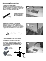
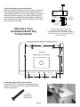
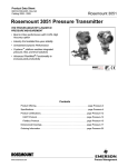
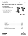
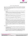
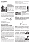
Note: Rockler may not carry all products and/or sizes listed in this vendor's publication
(29126)
Owner's Manual
Keep this manual handy for
quick reference
Stock No. 40-032
(fomerly RT400)
Congratulations and thank you for buying our
ProTop Standard router top! If you have any
questions, please give us a call. This manual will
assist you during the assembly of your router table.
However, this manual is not intended as an
instructional manual for router table usage. Please
consult the widely available books, magazines, and
classes on router table techniques.
Thank you for choosing Bench Dog!
Contents of Box
1
1
1
router top
phenolic ProPlate
32" miter track
Hardware
12
7 x 40mm insert plate leveling screws
2
1/4-20 x 1" phil. flat head mach. screws
14
1/4-28 x 1/2" set screws
4
1/4-20 x 2" phil. flat head mach. screws
4
1/4-20 x 2" round head bolts
8
1/4-20 cross dowels
1
4mm hex wrench
2
trim strips
4
#6 x 1/2" screws
Requirements
Assembly
4mm hex wrench (supplied)
1/8" hex wrench (supplied)
screwdriver and power drill
Mounting Router
drill bit (sized to your router mounting screws)
Bench Dog, Inc.
countersink 82 degree
3310 5th St. NE
Minneapolis, MN 55418
drill press (recommended)
612.782.8205 main
612.788.2518 fax
800.786.8902 toll free
[email protected]
benchdog.com
QUESTIONS?
1-800-786-8902
Be sure to check out our web site for all the
latest and greatest accessories and tools.
www.benchdog.com
Read and understand the entire contents
of this manual before attempting assembly
or operation of this tool! Inspect contents
for shipping damage and shortages. Report
problems directly to Bench Dog, Inc.
2004 Bench Dog, Inc.
82-0009-06 0904
RTD10000534AA
General Conditions / Limited Two Year Warranty
LIMITED TWO-YEAR WARRANTY
We make every effort to assure that our products meet quality and durability standards, and warrant to the original retail purchaser that this
product is free from defects in materials and workmanship for two years. Remedy shall be limited to Bench Dog’s choice of repair,
replacement or refund. This warranty does not provide remedy for consequential economic loss.
This is a limited two year warranty. It requires the purchaser to contact Bench Dog in writing within 30 days of discovering the defect.
Warranty does not apply to defects due directly or indirectly to misuse, abuse, negligence or accidents, repairs or alterations, or due to lack
of maintenance. It excludes components and parts not manufactured by Bench Dog, defects caused by failure to provide a suitable
installation environment, and damage caused by use for purposes other than those for which the product was designed. Bench Dog, Inc.
reserves the right to make product changes without notice and without obligation to make these changes on products previously sold. It
excludes warranties of fitness for a particular purpose.
If the product is defective, we reserve the right to fix it, replace it, or refund the cost of the product to you. Typically, this results in a refund.
All claims are limited to the two-year claims period. We must receive the product before a credit or refund will be issued. The warranty
language on the product or in the product’s manual may contain additional limitations, which govern.
If you wish to return something, call the dealer where you purchased the product. If you wish to return something purchased from Bench
Dog directly, call 1-800-786-8902 to receive an RMA number. Upon receipt and inspection of the goods, a credit or replacement will be
issued for defective products. Return of nondefective items to Bench Dog are subject to a 7% restocking charge. This is necessary due to
the cost of checking, repackaging, and inventorying the stock.
BENCH DOG DISCLAIMS AND BUYER EXPRESSLY WAIVES ANY AND ALL WARRANTIES, EXPRESS OR IMPLIED, INCLUDING BUT
NOT LIMITED TO, IMPLIED CONDITIONS OF FITNESS FOR A PARTICULAR PURPOSE, MERCHANTABILITY, OR ANY OTHER
MATTER.
Important Safety Points
Before operating your router table please read this manual thoroughly. Safety and use tips are contained in the manual.
This page is not the sole source of safety information. Retain the manual for future reference. Refer to your router
owner's manual for safety instructions regarding use of that tool. This manual is not an instruction book on how to do
woodworking with a power tool. We encourage all woodworkers to continually seek improvement in their woodworking skills,
regardless of their craftsmanship or years of experience. The router table, fence and accessories must only be used for their
intended purpose: woodworking via normal routing operations. “Normal operations” means basic shaping of wood in
conditions where grounded electricity, sharp tools, dust, and rapidly spinning parts can be used or encountered safely. The
following instructions elaborate on this concept.
1.
2.
3.
4.
5.
6.
7.
8.
9.
10.
11.
12.
13.
14.
15.
Do not use your router table as a step or seat.
The top and cabinet must be properly secured, and be level before use. Inspect your table and base for
damage and levelness prior to each use.
Keep work area clean, dry and well lit.
The hardware affixing the insert to the routertop must be installed for safe use. Tighten insert hold-down
screws before each use.
Safe operation requires a router table fence, bit guard, dust collection system, starting pin or fulcrum, and
speed reducer for large diameter bits. We recommend reducing router speed for 1" or larger diameter bits.
Consult your bit manufacturer for the exact speed.
Use the right tool for the job. Do not force a tool or attachment to do a job for which it was not designed.
Secure your work with a featherboard, clamps, or a vice when appropriate. The use of inappropriate
accessories may cause injury.
Wear safety glasses, dust mask, face shield and ear protection. This is not an exhaustive list. Every-day
eye glasses do not substitute for safety glasses.
Do not wear gloves or jewelry while using a power tool and ProTop.
Maintain your equipment and its accessories in good working condition. Look for wear, poor alignment of
moving parts, binding of moving parts, breakage, poor mounting, or other conditions that may affect
operation and safety. Repair or replace any damaged parts.
Disconnect the power before moving, adjusting, or repairing parts, or otherwise maintaining your router table
and any accessories you may be using.
Keep children, pets, and those who may disregard safety away from work area, cords, sockets and tools.
Wear snug fitting clothes and keep long hair back to avoid catching in moving parts.
Do not overreach. Maintain balanced footing and stance.
Stay alert. Use common sense.
Page 2
Assembly Instructions
1. Install the (12) leveling screws.
Remove the router insert plate from the routertop, and
place the routertop face down, as shown. Using a power
drill, drive the screws in until they just come through the
other side. You will fine adjust them in step 8.
7 x 40mm
leveling
screw
Install the leveling screws
into the (12) small holes.
Do not install them into
the two larger holes near
the other small holes.
2. Attach the (2) trim strips to the routertop.
Use the (4) small #6 x 1/2 screws. Use a Phillips
screwdriver and install by hand. Be careful not to over
tighten the screws. Do not use a power drill in this step!
The trim strips are purely decorative. Position the trim
strip as shown, and drive the screws into the bottom of the
routertop.
!
1
2
Trim strips mount into
the bottom of the routertop!
3. Attach the routertop to your ProTop Cabinet.
Go to step 4 if you are building your own cabinet.
Use the (4) 1/4" round head bolts and (4) 1/4" cross
dowels. Always install the cross dowels first! The
drawing below shows how these strong but simple
fasteners fit together.
1/4-20"
cross dowel
3
Bolt
Panel
Cross Dowel
1/4-20 x 2"
round head bolt
Panel
Page 3
Bolt
4. Mount routertop to your custom base.
When mounting the routertop to your own base or leg set, use
the routertop's predrilled mounting holes with the bolts and
cross dowels provided. Use of any other hardware or mounting
method will void the warranty. You must locate and drill (8)
mounting holes according to the drawing below. Furthermore,
you must drill (8) cross dowel holes to intersect the mounting
holes, as shown to the right.
Routertop
Locate the center
of cross dowel
hole 3/4" from top of
panel, as shown.
3/4"
1-5/8"
Cross Dowel
The cross dowel hole
is 7/16" in diameter,
9/16" deep!
Skip step 4 if you
purchased a Bench Dog
ProTop Cabinet!
Cabinet Panel
The above drawing is provided to assist
you in locating the mounting holes for the
base you build. It is your responsibility to design an
adequately strong base to support the routertop, a
router, and your work.
All distances are from center of hole to center of hole.
416
16.378"
123.8
4.875"
123.8
187.3
7.374"
Top View
Dimensions in mm/inches.
Router Insert Plate
292.1
11.5"
Miter Track
75.8
2.984"
Drill the
5/16" diameter
routertop mounting
holes 1-5/8" deep,
as shown.
Miter Track
128
5.039"
192
7.559"
5. Attach the miter track to the routertop.
First install (4) 1/4" cross dowels in the cabinet's front
stretcher. Use the (4) 1/4-20 x 2" phil. flat head machine
screws in track holes.
1/4-20 x 2"
phil. flat head
machine screw
Page 4
192
5
75.8
6. Adjust miter gauge track to fit your miter gauge.
First test fit your miter gauge into the track. If it's too tight,
squeeze the gib against the front wall of the miter track with a
pair of Channel Locks, use a shop towel to prevent marring.
Next, install the (14) 1/4-28 x 1/2" set screws. Tightening the
screws will deflect the gib into your miter gauge. Tighten all
screws uniformly and gradually until the desired fit is achieved.
6
SQUEEZE
TO LOOSEN
1/4-28 x 1/2"
set screw
front
wall
gib
7
This miter track ONLY fits standard 3/8" x 3/4" miter
gauge bars. Wax the slot and bar to reduce wear.
7. Mount your router to the phenolic insert plate.
This insert plate is undrilled. You must drill your own
router mounting holes. Please reference the included
template to complete this step.
Router not included!
8
8. Adjust the leveling screws until the insert is flush.
Install the insert plate and adjust the leveling screws until
the plate is flush with router top. Fine adjust the six screws
at the four corners of the insert opening first.
9. Install the (2) insert plate hold-down screws.
The (2) 1/4-20 x 1" phil. flat head machine screws prevent
side to side movement, as well as keep the plate firmly
seated. Readjust the plate flush if necessary. Tighten the
hold-down screws before every use, if necessary!
9
1/4-20 x 1"
phil. flat head
machine screw
Page 5
Page 5
Operational Use Tips
Feed Direction
Always feed the workpiece against the cutter
rotation, as shown. Feeding the workpiece with
the cutter rotation is called "climb cutting". Climb
cutting is very dangerous, because the cutter will
grab the workpiece and thrust it the same direction
as the cutter rotation. Even small router bits will
overpower your ability to hold onto the workpiece
during a climb cut.
A typical set-up. Here, the fence is
partially covering the router bit.
routertop (top view)
router bit rotation
Fence
Do not use this router table until you understand
proper feed direction and bit rotation. If climb
cutting is still unclear, ask your retailer for help,
give us a call, or reference a book on router table
usage.
!
workpiece
Proper feed direction
Never Climb Cut!
Avoiding Fence Traps
Fence traps occur when the work piece is fully
"trapped" between the router bit and fence. Fence
traps pose two real concerns: the possibility of climb
feeding, and human exposure to the router bit. As
stated earlier, climb cutting should be avoided as loss
of control of the operation is a possibility!
A classic trap resulting in a climb
cut. Always avoid this set-up!
Fence
workpiece
The top drawing shows a classic trap to be avoided.
What appears as a normal feed direction (working
from right to left) is wrong, and will instead produce a
climb cut. Because the work piece is trapped it can
easily be pulled from one's grip and thrown with great
velocity. Feeding the stock from left to right will
eliminate the climb cut but not the danger. It will be
difficult to keep the stock tight against the fence as the
bit's rotation will thrust the stock away from the fence.
Also, your body will be dangerously exposed to the
spinning router bit. The bit guard will not protect you
against flying stock, nor guard against this level of
exposure.
The second drawing is not a trap, as long as the router
bit cuts only partially into the stock. In other words, the
router bit must not completely cut through the
workpiece. In this cut, the bit will grab and push the
stock toward the fence. This is good, as the fence will
control the workpiece better than your hands. Typical
dado cuts resemble this set-up, and are commonly
performed on router tables. If the dado is to be
widened with two (or more) passes, be careful not to
set a classic trap or climb cut.
NO!
b it
r o t a ti o n
This feed direction will
result in a climb cut because
the stock is trapped between
the fence and the router bit.
Not a trap as long as the router bit does not
cut all the way through the stock.
Fence
OK for
dadoes
only
workpiece
b it
r o t a ti o n
Here the feed direction is
correct because the router
bit does not cut all the way
through the stock.
Page 6