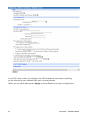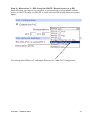
1
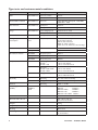
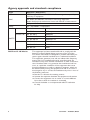
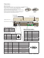
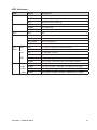
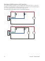
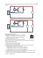
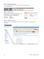
DR-270 DR-270 DSL Router LAN POWER 0 3G/GPRS 1 2 3 WIFI DSL NET SIM SIGNAL DAT SIM 1 SIM 2 Multiple Media ADSL/VDSL2 Router www.westermo.com © Westermo Teleindustri AB User Guide 6622-2241 29000589, REV.A Legal information The contents of this document are provided “as is”. Except as required by applicable law, no warranties of any kind, either express or implied, including, but not limited to, the implied warranties of merchantability and fitness for a particular purpose, are made in relation to the accuracy and reliability or contents of this document. Westermo reserves the right to revise this document or withdraw it at any time without prior notice. Under no circumstances shall Westermo be responsible for any loss of data or income or any special, incidental, and consequential or indirect damages howsoever caused. More information about Westermo can be found at the following Internet address: http://www.westermo.com 2 6622-2241 • 29000589, REV.A Safety Before using this unit: Read this manual completely and gather all information on the unit. Make sure that you understand it fully. Check that your application does not exceed the safe operating specifications for this unit. Hazardous voltages may occur within this unit when connected to a power supply. Prevent access to hazardous voltages by disconnecting the unit from its power supply. Prevent damage to internal electronics from electrostatic discharges (ESD) by discharging your body to a grounding point (e.g. use of wrist strap). Before installation: This unit should only be installed by qualified personnel. This unit should be built-in to an apparatus cabinet, or similar, where access is restricted to service personnel only. The power supply wiring must be sufficiently fused, and if necessary it must be possible to disconnect manually from the power supply. Ensure compliance to national installation regulations. This unit uses convection cooling. To avoid obstructing the airflow around the unit, follow the spacing recommendations (see Installation section). Care recommendations Follow the care recommendations below to maintain full operation of unit and to fulfil the warranty obligations. This unit must not be operated with covers or lids removed. Do not attempt to disassemble the unit. There are no user serviceable parts inside. Do not drop, knock or shake the unit, rough handling beyond the specification may cause damage to internal circuit boards. Do not use harsh chemicals, cleaning solvents or strong detergents to clean the unit. Do not paint the unit. Paint can clog the unit and prevent proper operation. Do not expose the unit to any kind of liquids (rain, beverages, etc). The unit is not waterproof.‑Keep the unit within the specified humidity levels. Do not use or store the unit in dusty, dirty areas, connectors as well as other mechanical part may be damaged. If the unit is not working properly, contact the place of purchase, nearest Westermo distributor office or Westermo Tech support. GSM specific safety Please read and follow the guidelines listed below. The precautions must be observed during all phases of the operation. Breaking these rules may be dangerous, illegal or affect performance of the unit and/or invalidate the unit’s approval and/or warranty. 6622-2241 • 29000589, REV.A 3 General Remember to follow any special regulations and warnings in force in any area and never use the unit whenever it’s forbidden to use it. Do not use the unit when it may cause interference or danger. A wireless device exposed to interference above specified limits could result in deteriorated performance. Hospitals or other Medical environment Do not use the unit in a medical environment such as health care facilities. Follow any regulations or rules that instruct you to not use the unit. Pacemakers The Health Industry Manufacturers Association recommends that a minimum separation of six (6”) inches be maintained between cellular wireless equipment and a pacemaker to avoid potential interference with the pacemaker. These recommendations are consistent with the independent research by and recommendations of‑Wireless Technology Research. Persons with pacemakers: … Should ALWAYS keep the the unit and its antenna more than six inches from their pacemaker when the unit is turned ON. … If you have any reason to suspect that interference is taking place, turn your wireless equipment OFF immediately. Hearing Aids Some digital wireless equipment may interfere with some hearing aids. In the event of such interference, you may want to consult your service provider [or call the customer service line to discuss alternatives.] Other Medical Devices If you use any other personal medical device, consult the manufacturer of your device to determine if they are adequately shielded from external RF energy.‑Your physician may be able to assist you in obtaining this information. Turn the wireless equipment OFF in health care facilities when any regulations posted in these areas instruct you to do so. Hospitals or health care facilities may be using equipment that could be sensitive to external RF energy. Aircraft Do not use the unit in an aircraft. The use of a wireless unit in an aircraft may be dangerous to the operation of the aircraft, disrupt the wireless network, and may be illegal. Failure to observe these instructions may lead to suspension or denial of cellular services to the offender, legal action, or both. Vehicle If the unit is incorrectly installed in a vehicular environment, the operation of the unit could interfere with the vehicle electronics. Faulty installation and/or operation can constitute a safety hazard. 4 6622-2241 • 29000589, REV.A For Vehicles equipped with an airbag An air bag inflates with great force. DO NOT place objects, including either installed or portable wireless equipment, in the area over the air bag or in the air bag deployment area. If in-vehicle wireless equipment is improperly installed and the air bag inflates, serious injury could result. Blasting areas Do not use the unit where blasting is in progress or in “blasting areas”. Observe restrictions and follow any regulation or rules. Explosive atmospheres Do not use the unit in any area with a potentially explosive atmosphere. Potentially explosive areas are often, but not always, clearly marked. They include fuelling areas such as petrol stations, below decks on boats, fuel or chemical transfer or storage facilities, and areas where the air contains chemicals or particles, such as grain, dust, or metal powder. RF energy The DR-270/3G is a low power radio transmitter and receiver. When it is ON, it receives and also sends out radio frequency (RF) signals. Most modern electronic equipment is shielded from RF signals. However, certain electronic equipment may not be shielded against the RF signals from the wireless unit. All radio-transmitting devices send signals, which may cause interference in different electronic devices. To avoid interference, place the units antenna a sufficiently long distance from other electronics. Critical applications Cellular units operate using radio signals and cellular networks cannot be guaranteed to connect in all conditions. Therefore you should never rely solely on a wireless device for essential communications, for example medical emergencies. Backup copies Remember to make backup copies of all important data, for example PIN/PUK codes, contents of SIM card etc. Antenna care Use only the supplied or an approved replacement antenna. Unauthorized antennas, modifications, or attachments could damage the unit and may violate current regulations. Do not touch the antenna unnecessarily when the unit is in use. Contact with the antenna affects call quality and may cause the unit to operate at a higher power level than otherwise needed. Maintenance No maintenance is required, as long as the unit is used as intended within the specified conditions. 6622-2241 • 29000589, REV.A 5 Type tests and environmental conditions Phenomena Test Description Test levels ESD EN 61000-4-2 Enclosure contact ± 4 kV Enclosure air ± 8 kV RF field AM modulated EN 61000-4-3 Enclosure 3 V/m 80% AM (1 kHz), 80 – 1000 MHz, 1400 MHz – 2000 Fast transient EN 61000-4-4 Signal ports ± 0.5 kV Power ports ± 1 kV Telecom/Signal ports ± 0.5 kV line to earth Power ports ± 2 kV line to earth, ± 2 kV line to line Surge EN 61000-4-5 RF conducted EN 61000-4-6 Power ports 3V/m 80% AM (1 kHz), 0.15 – 80 MHz Voltage dips and interruption EN 610004-11 AC power ports 10 & 100 ms, interruption 10 ms, 30% reduction 100 ms, 60% reduction 5000 ms, >95% reduction +30% above & –20% below rated voltage Radiated emission EN 55022 Enclosure Class B FCC part 15 Conducted emission AC power ports Class A FCC part 15 AC power ports Class B EN 55022 DC power ports Class B Operating DR-270 DR-270 + 3G –40 to +75º Celsius –40 to +167º Fahrenheit Operating DR-270 + 3G + WiFi DR-270 + WiFi –20 to +75º Celsius –68 to +167º Fahrenheit Temperature Humidity Altitude Reliability prediction (MTBF) Class B EN 55022 Storage & Transport –40 to +85º Celsius –40 to +185º Fahrenheit Operating 5 to 95% relative humidity Storage & Transport 5 to 95% relative humidity Operating 2000 m / 70 kPa Bellcore RQGR at 40°C Models and their values DR-270 125361 h DR-270 + WiFi 105455 h DR-270 + 3G 105015 h DR-270 + 3G + WiFi 90677 h Enclosure Pressed steel Dimension W x H x D 262 x 40.5 x 141 mm 10.3 x 1.6 x 5.5 inches Weight Degree of protection 6 1.4 kg IEC529 Enclosure IP 30 Cooling Convection Mounting Horizontal on 35 mm DIN-rail or flat on level surface 6622-2241 • 29000589, REV.A Description Remote access removes boundaries, eliminates the need for time consuming site visits and provide a network infrastructure suitable for today's “always-on” society. The DR-270 ADSL / VDSL2 router uses the Internet to cost effectively inter-connect systems, allowing HMI, PLCs, sensors etc to communicate with each other. The optional multiple media interfaces ensures high availability for critical applications. Mobile broadband (3G) in conjunction with ADSL/VDSL2 protects against digging accidents or other issues that may occur in a wired environment. Devices connected to the Internet require countermeasures towards cyber threats. The DR-270 offers protection of transmissions from malicious eavesdroppers via encrypted communication tunnels (VPN), access prevention from unauthorized addresses, and extensive logging to detect intrusion attempts. With an advanced and highly configurable firewall the unit is easily set up to only allow valid application data. 141 ±1 Certain carriers discontinue leased line service to its customers but that does not mean that 136 ±0,5 the need for communication has changed. The DR-270 with its built-in serial port offers a simple solution, modem replacement, with the benefit of not having to reprogram or change any other component. The powerful software in the DR-270 offers methods to engineers to easily analyze the data-flow, valuable for fast troubleshooting of connected devices. Dimensional drawing 40,5 ±1 262 ±0,5 141 ±1 136 ±0,5 40,5 ±1 262 ±0,5 6622-2241 • 29000589, REV.A 7 Agency approvals and standards compliance Type Approval / Compliance EN 55024, EN 55024 A1, EN 55024 A2, Electromagnetic compatibility Immunity IT equipment EMC EN 55022, EN 55022 A1, Information technology equipment. Radio disturbance characteristics. Limits and methods of measurement FCC part 15 Class B Safety IEC / EN 60950-1, IT equipment Article 3.1a Article 3.1b R&TTE Article 3.2 EN 60950 Safety EN 50385 EMF exposure EN 301 489-1 ERM/EMC EN 301 489-7 ERM/EMC GSM EN 301 489-24 ERM/EMC 3G EN 301 908-1 ERM 3G EN 301 908-2 ERM 3G EN 301 511 GSM FCC Part 15.105 Notice:This equipment has been tested and found to comply with the limits for a Class B digital device, pursuant to Part 15 of the FCC Rules. These limits are designed to provide reasonable protection against harmful interference in a residential installation. This equipment generates, uses and can radiate radio frequency energy and, if not installed and used in accordance with the instructions, may cause harmful interference to radio communications. However, there is no guarantee that interference will not occur in a particular installation. If this equipment does cause harmful interference to radio or television reception, which can be determined by turning the equipment off and on, the user is encouraged to try to correct the interference by one or more of the following measures: … Reorient or relocate the receiving antenna … Increase the separation between the equipment and receiver … Connect the equipment into an outlet on a circuit different from that to which the receiver is connected … Consult the dealer or an experienced radio/TV technician for help. 8 6622-2241 • 29000589, REV.A Declaration of Conformity Westermo Teleindustri AB Declaration of conformity The manufacturer Westermo Teleindustri AB SE-640 40 Stora Sundby, Sweden Herewith declares that the product(s) Type of product Model Art no Cellular router DR-270A series 3622-0310, 3622-0315, 3622-0320, 3622-0325 DR-270B series 3622-0340, 3622-0345, 3622-0350, 3622-0355 is in conformity with the following EC directive(s). No Short name 1999/5/EC Radio equipment and Telecommunications terminal equipment (R&TTE) 2011/65/EU Restriction of the use of certain hazardous substances in electrical and electronic equipment (RoHS) References of standards applied for this EC declaration of conformity. No Title Issue EN 60950-1 Information technology equipment - Safety – General requirements EN 61000-3-2 Electromagnetic compatibility (EMC): Limits - Limits for harmonic current emissions EN 61000-3-3 Electromagnetic compatibility (EMC) : Limits - Limitation of voltage changes, voltage fluctuations and flicker in public low voltage supply systems. Electromagnetic compatibility and Radio spectrum Matters (ERM); ElectroMagnetic Compatibility (EMC) standard for radio equipment and services: Specific conditions for mobile and portable radio and ancillary equipment of digital cellular radio telecommunications systems (GSM and DCS) Global System for Mobile communications (GSM); Harmonized EN for mobile stations in the GSM 900 and GSM 1800 bands. Electromagnetic compatibility and Radio spectrum Matters (ERM); Harmonized EN for CDMA spread spectrum mobile stations operating in the 450 MHz cellular band (CDMA 450) and 410, 450 and 870 MHz PAMR bands. IMT cellular networks; Harmonized EN covering the essential requirements of article 3.2 of the R&TTE Directive; Part 1: Introduction and common requirements IMT cellular networks; Harmonized EN covering the essential requirements of article 3.2 of the R&TTE Directive; Part 2: CDMA Direct Spread (UTRA FDD) User Equipment (UE) Information technology equipment – Immunity characteristics Limits and methods of measurement 2006 +A11:2009 +A1:2010 +A12:2011 2006 +A1:2009 +A2:2009 2008 EN 301489-7 EN 301 511 EN 301 526 EN 301 908-1 EN 301 908-2 EN 55024 EN 55022 Information technology equipment – Radio disturbance characteristics – Limits and methods of measurement The last two digits of the year in which the CE marking was affixed: V1.3.1 V9.0.2 V1.1.1 V5.2.1 V5.2.1 1998 +A1:2001 +A2:2003 2006 +A1:2007 13 Pierre Öberg Technical Manager 30th July 2013 Postadress/Postal address Tel. Telefax Postgiro Bankgiro Org.nr/ Corp. identity number Registered office S-640 40 Stora Sundby Sweden 016-428000 Int+46 16428000 016-428001 Int+46 16428001 52 72 79-4 5671-5550 556361-2604 Eskilstuna 6622-2241 • 29000589, REV.A 9 Interface specifications Power Rated voltage Operating voltage Power consumption 9 – 36 VDC 9 – 36 VDC DR-270 – typical: 1.02 A = 12.24 W, max: 1.03 A = 12.36 W DR-270 + WiFi – typical: 1.12 A = 13.44 W, max: 1.140 A = 13.68 W DR-270 + 3G – typical: 1.23 A = 14.76 W, max: 1.24 A = 14.88 W Rated frequency DR-270 + 3G + Wi-Fi – typical: 1.31 A = 15.72 W, max: 1.42 A = 17.04 W DC RS-232 Electrical specification Data rate Data format Protocol Circuit type Transmission range Connection Shielded cable Conductive housing Number of ports EIA RS-232 300 bit/s – 115.2 kbit/s 7 or 8 data bits, Odd, even or none parity, 1 or 2 stop bits Transparent, optimised by packing algorithm SELV 15 m / 49 ft 9 pin D-sub female Not required Yes 1 Ethernet TX Electrical specification Data rate IEEE std 802.3. 2005 Edition 10 Mbit/s, 100 Mbit/s, manual or auto Duplex Full or half, manual or auto Circuit type SELV Transmission range 100 m / 328 ft Isolation to All other Connection RJ-45 auto MDI/MDIX Shielded cable Conductive housing Not required, except when installed in Railway applications as signalling and telecommunications apparatus and located close to rails.* Yes Number of ports 4 * To minimise the risk of interference, a shielded cable is recommended when the cable is located inside 3 m boundary to the rails and connected to this port. The cable shield should be properly connected (360º) to an earthing point within 1 m from this port. This earthing point should have a low impedance connection to the conductive enclosure of the apparatus cabinet, or similar, where the unit is built-in. This conductive enclosure should be connected to the earthing system of an installation and may be directly connected to the protective earth. 10 6622-2241 • 29000589, REV.A Antenna (option) Frequency bands Connection 850 MHz – 2100 MHz SMA female, impedance: 50 ohm SIM (option) Electrical specification Number of slots 3 volts SIM supported 2 USB Electrical specification Data rate Circuit type Maximum supply current Connection Number of ports USB 2.0 host interface Up to 12 Mbit/s (full-speed mode) SELV 500 mA in total for both ports USB receptacle connector type A 1 DSL Data rate Protocol Connection Shielded cable Number of ports Standard ETSI TS 101 270 ITU-T 993.2 (VDSL2) T1.424 ITU-T G.992.1 (ADSL) ITU-T G.992.3 (ADSL2) ITU-T G.992.5 (ADSL2+) ANSI T1.413 100 Mbit Downlink, 100 Mbit Uplink LLC/VC-MUX encap Ethernet, PPPoA, PPPoE, IPoA RJ-11 Not required, except when installed in Railway applications as signalling and telecommunications apparatus and located close to rails.* 1 Annex N/A A, B, J N/A A,B (non overlap) A,B,I,J,L,M (non overlap) A,B,I,J,M (non overlap) N/A * To minimise the risk of interference, a shielded cable is recommended when the cable is located inside 3 m boundary or the cable is longer than 30 m and inside 10 m boundary to the rails and connected to this port. WiFi (option) Connection Data Rate Standard Transmit power Receive sensitivity 6622-2241 • 29000589, REV.A 2 x 50 Ω RP-SMA (Center pin: male) 11 – 54 Mbit/s 802.11b/g/n 20 dBm +1.0 / –1.5 dBm 11 Mbps / –90 dBm, 54 Mbps / <–72 dBm 11 Connections SIM Card Sockets The two sockets at the left side of the front panel are for the GSM SIM card(s) that you will receive from your service providers. SIM 1 and SIM 2 cannot be used to access two networks simultaneously. The SIM card(s) should be inserted into SIM cardholders on the right of the front panel as illustrated below. In both cases, the end of the SIM card with the chamfered corner should be inserted first. For SIM 1 the contacts should be face down. For SIM 2 the contacts should be face up. LED Indicators (for details see next page) SIM card sockets DR-270 DSL Router USB Host Connector 0 1 SIGNAL 3G/GPRS LAN POWER SIM 1 2 3 WIFI DSL NET SIM SIM 2 DAT Antenna interface (optional) 9-36VDC, 3,5A WWAN PRIMARY MAIN WIFI SECONDARY WWAN SECONDARY DSL SERIAL 0 AUX. WIFI PRIMARY LAN3 LAN2 LAN1 LAN0 DSL interface Power interface cord Cable Description Black – VDC Red + VDC Ethernet TX Connections (RJ-45 connector) LAN 0–3 Pin-out interface Pin Wire Color Signal 1 Black Gnd 2 Blue Input 3 Green Input/Output 4 Red Power 4 2 3 1 Position Direction Description 1 In/Out TD+ 2 In/Out TD– 3 In/Out RD+ 4 – Not Connected 5 – Not Connected 6 In/Out RD– 7 – Not Connected 8 – Not Connected RS-232 interface (DCE Female) Position Name Direction Description 1 DCD Out Data Carrier Detect 2 RxD Out Receive Data 3 TxD In Transmit Data 4 DTR In Data Terminal Ready 12 5 SG – Signal Ground 6 DSR Out Data Set Ready 7 RTS IN Request to Send 8 CTS Out Clear to Send 9 RI Out Ring Indicator 1 6 5 9 6622-2241 • 29000589, REV.A LED Indicators LED Status Description PWR OFF Unit has no power GREEN All OK RED Lit until unit has started up OFF No link GREEN Link established GREEN FLASH Data traffic indication WIFI N/A N/A DSL RED No DSL link GREEN DSL link established RED FLASH DSL link negotiation GREEN BLINK Data traffic indication OFF No wireless network has been detected GREEN A wireless network has been detected OFF No valid SIM installed GREEN A valid SIM card is installed in the unit OFF No data is being transferred over the wireless network GREEN Data is being transferred over the wireless network OFF No signal / less than –113 dBm 1 LED GREEN Low signal strength / between –112 dBm and –87 dBm 2 LEDs GREEN Medium signal strength / between –86 dBm and –71 dBm 3 LEDs GREEN Strong signal strength / between –70 dBm and –51 dBm LAN 0,1,2,3 3G / GPRS NET SIM DAT SIGNAL ALL 6622-2241 • 29000589, REV.A 13 Description of AUX-connector and I/O signal lines The auxiliary power connector has two programmable signal lines. One is an input line, the other can be configured as either an input line or an output line. The mode of operation of the input/output line is configurable through the CLI. The signal lines can be wired as shown in the following diagrams POWER Switch Switch INPUT/OUTPUT + INPUT 11 – 28 V – GND 2 Inputs, Supply Voltages up to 28 VDC POWER Switch Switch INPUT/OUTPUT + + INPUT 4 – 28 V 11 – 28 V – – GND 2 Inputs, Supply Voltages up to 58 VDC 14 6622-2241 • 29000589, REV.A If the auxilary power connector is being used, the main power connector should NOT be used. POWER Relay Switch INPUT/OUTPUT + INPUT 11 – 28 V – GND 1 Input, 1 Output, Supply Voltages up to 28 VDC POWER Relay Switch INPUT/OUTPUT + + INPUT 4 – 28 V 11 – 28 V – – GND 1 Inputs, 1 Output, Supply Voltages up to 58 VDC Input Signal Information … Applied input voltage to activate: +4 V to +28 VDC … Applied input voltage to deactivate: 0 V to +1 VDC (Negative voltages can be applied to –28 VDC) Connector Pin Numbers … Maximum input current: 3 mA … Input protection activates at more than ±28 VDC. External current limiting is needed to protect input voltages above ±28 VDC. Output Signal Information … Maximum voltage switched: +28 VDC … Maximum current switched: +40 mA … Output leakage current is equivalent to a 10 Kohms resistor to Ground. … Suggested minimum Relay Coil resistances: • Supply Voltage 6 VDC, minimum resistance 100 Ohms • Supply Voltage 12 VDC, minimum resistance 240 Ohms • Supply Voltage 24 VDC, minimum resistance 480 Ohms … The output switch is protected against back-EMFs generated at relay turn-off. … Output protection activates at more than ±28 VDC. External current limiting is needed to protect input voltages above ±28 VDC. 6622-2241 • 29000589, REV.A 15 Protocols and Functionality Ethernet Technologies IEEE 802.3 for 10BaseT IEEE 802.3u for 100BaseTX ADSL Technologies ITU-T G.992.1 ADSL (Annex A, B (non overlap)) ITU-T G.992.2 ADSL Lite (Annex A (non overlap)) ITU-T G.992.3 ADSL2 (Annex A, B, I, J, L, M (non overlap)) ITU-T G.992.5 ADSL2+ (Annex A, B, I, J, M (non overlap)) ITU-T 993.2 VDSL2 (Annex A, B, J) RFC2684 Bridged LLC and Bridged VC-MUX ATM encap. (ADSL) ADSL2++ Quad spectrum downstream and double upstream Cellular Technologies (optional) GSM GPRS Multi-slot class 12, mobile station class B, PBCCH support, coding schemes CS 1-4 EDGE Multi-slot class 12 (max 236.8 Kbit/s), mobile station class B, modulation and coding scheme MCS 1-9 3G (WCDMA) 384 Kbit/s downlink / uplink HSDPA up to 14.4 Mbit/s downlink HSUPA up to 5.7 Mbit/s uplink EV-DO Rev A WiFi Technologies (optional) Modes + Access point + Client + Multiple SSID Security + WEP (64 and 128 bit) encryption + WPA/WPA2 with Radius (WPA Enterprise and pre-shared keys) Serial Port Technologies RS-232 Serial Over IP (Serial Extender and Virtual Serial Port) LAPB Resiliency and High Availability IEEE 802.1D Spanning Tree Protocol (STP) IEEE 802.1w Rapid STP (RSTP) Layer-2 Switching IEEE 802.1Q Static VLAN and VLAN Tagging IEEE 802.3x Flow Control IGMPv2/v3 snooping Static Multicast MAC filters Layer-2 QoS IEEE 802.1p Class of Service Flexible classification VLAN tag, VLAN ID, IP DSCP/ToS, Port ID) 16 6622-2241 • 29000589, REV.A IP Routing, Firewall, VPN and Cyber Security Static IP routing Dynamic IP routing • BGP • OSPFv2 • RIPv1/v2 VRRP, VRRP+™ GRE Stateful inspection Firewall / ACL, NAT, 1:1 NAT, Port Forwarding IPSec VPN including failover functionality, PSK & X.509, SCEP • 20 Encrypted tunnels included, supports 200 tunnels in total with upgrade. L2TP, PPTP OpenVPN / SSL VPN TACACS+ RADIUS SMS Control (Requires 3G Option) Manageability Management tools • Web interface (HTTP and HTTPS) • Command Line Interface (CLI) via console port, SSHv2 and TELNET • SNMPv1/v2c/v3 • Powerful Packet/Protocol Analyzer with PCAP-export support • Flexible management of configuration and log files • Local file management via HTTP, FTP, TFTP and SCP • Load/save files from/to USB memory stick • Upgrade firmware from USB memory stick Flexible alarm/event handling system Syslog (log files and remote syslog server) Port Monitoring SNTP (NTP client) PPPoA & PPPoE client DHCP server & client DDNS Programming Custom Control ScriptBasic Python 6622-2241 • 29000589, REV.A 17 Factory default/reset Perform the following 4 steps to reset the unit to its factory default settings. 1. Power up the unit. 2. Locate the reset switch on the underside of the unit, near the front ventilation holes. 3. Press and hold the reset switch gently, with the tip of a pen or other similar device, until you see the front LEDs flashing (~5 sec). 4. Remove the tip of the pen and wait for the unit to reboot. Note! Do not power off the unit while the factory reset procedure is in place Default Network Settings IP address (Ethernet ports) Netmask (Ethernet ports) Username Password 192.168.2.200 255.255.255.0 admin westermo Default DSL Settings DSL Connection type VPI / VCI Authentication ADSL/ADSL2/ADSL2+ on Annex A 0 / 38 PPPoA Reset/set IP address using an RS-232 serial connection If the IP address of the device is unknown the best way to access the unit is by performing a factory reset, however, in some instances it may be required to only change, or set, the IP address of the device. This can be achieved by connecting an RS-232 cable between the Serial 0 port on the device to your PC. RS-232 PC settings Data rate Data bits Stop bits Parity Flow control 115.200 bit/s 8 1 None None Execute the following commands and change them to match your desired network settings. Eth 0 ipaddr 192.168.2.200 Eth 0 mask 255.255.255.0 Eth 0 gateway 192.168.2.200 Eth 0 status Config 0 save The device can now be reached on the IP-address configured above. 18 6622-2241 • 29000589, REV.A DR-270 Step-by-step guide to configure a DSL-connection using the web interface DSL Router 9-36VDC, 3,5A WWAN PRIMARY MAIN AUX. 0 WIFI SECONDARY 1 SIGNAL 3G/GPRS LAN POWER ADSL connection (RJ-11) SIM 1 2 3 WIFI DSL NET SIM WWAN SECONDARY SIM 2 DAT WIFI PRIMARY DSL SERIAL 0 LAN3 LAN2 Power Connection LAN1 LAN0 PC/Ethernet connection (RJ-45) Step 1 – Power-up the unit and wait for it to become ready Connect the DR-270 to the DSL-network using the RJ-11, connect an RJ-45 cable from one of the four Ethernet-ports to your PC, and then connect the unit to an appropriate PSU and power it up. The unit will start to negotiate the DSL-connection after approximately 15 – 20 seconds, please note that the default settings might not be appropriate for your specific connection. Continue reading in order to assure that you have a valid setup. Step 2 – Configure your PC Make the following changes in your PC. IP address Netmask (Ethernet ports) Gateway Preferred DNS server 192.168.2.100* 255.255.255.0 192.168.2.200 192.168.2.200 * Can be any address in the 192.168.2.0-255-range except 192.168.2.200. Note! If you are unsure or unable to change the above – consult your network administrator. 6622-2241 • 29000589, REV.A 19 Step 3 – Accessing the unit Start a web browser on your PC and type in the following address http://192.168.2.200 Step 4 – Login screen After step 3 you will be presented with a login screen which asks for a username and a password. Please type in the following: Username admin Password westermo Step 5 – Welcome screen You have now successfully logged into the unit and are ready to set up your DSLconnection. Please click on Network under the Configuration-menu item. 20 6622-2241 • 29000589, REV.A Step 6 – Alternative 1 – DSL Setup for PPPoA (e.g. UK) / PPPoE (e.g. DE) The DR-270 comes pre-configured to match connections using ADSL with VPI/VCI set to 0/38, authentication via PPPoA. Should the default settings not match your connection you can always change the parameters to match your specific details. Then click on DSL under the Interface-context. Country Sweden Germany United Kingdom ADSL Settings per country Provider Annex Mode TeliaSonera A DHCP Deutsche Telekom (DT) B PPPoE British Telecom (BT) A PPPoA 6622-2241 • 29000589, REV.A ATM Enc. VPI / VCI LLC 8/35 LLC 1/32 LLC 0/38 21 In the DSL setup screen you configure the DSL-broadband connection according to the information you received from your service provider. When you are done, please press Apply and then Save to save your configuration. 22 6622-2241 • 29000589, REV.A Step 6 – Alternative 2 – DSL Setup for DHCP / Routed access (e.g. SE) Some ISPs does not require any username or password and usually provides Internet access via DHCP. To setup the DR-270 in those countries/ISPs please follow the actions below. First change from PPPoA LLC to Bridged Ethernet LLC under PVC Configuration 6622-2241 • 29000589, REV.A 23 Make sure that the radio-button for Get an IP address automatically using DHCP is selected. 24 6622-2241 • 29000589, REV.A Step 7 – Unit ready and online The DR-270 will immediately start to negotiate the DSL-connection with the new details after Step 6. To monitor the connection progress, navigate to Network Status→ Interfaces→ DSL. Under Modem Status you see the status of the DSL-connection. Step 8 – Test your connection In your Internet browser type in www.westermo.com and test your connection, you should be able to see the Westermo website. You are now ready to use the DR-270! Change the IP address of the unit First follow steps 1 through 5 above. Then click on Interfaces→ Ethernet → ETH 0 – LAN 0 Type the desired IP address into the text box next to IP Address and then press Apply and Save. 6622-2241 • 29000589, REV.A 25 Westermo • SE-640 40 Stora Sundby, Sweden Tel +46 16 42 80 00 Fax +46 16 42 80 01 E-mail: [email protected] www.westermo.com Sales Units Westermo Data Communications China [email protected] www.cn.westermo.com France [email protected] www.westermo.fr Germany [email protected] www.westermo.de North America [email protected] www.westermo.com Singapore [email protected] www.westermo.com Sweden [email protected] www.westermo.se United Kingdom [email protected] www.westermo.co.uk Other Offices For complete contact information, please visit our website at www.westermo.com/contact or scan the QR code with your mobile phone. REV.A 6622-2241 • 29000589, REV.A 2013-09 Westermo Teleindustri AB, Sweden – A Beijer Electronics Group Company