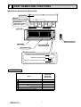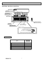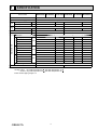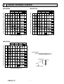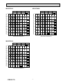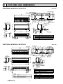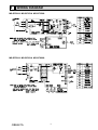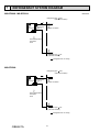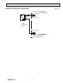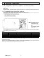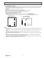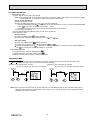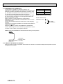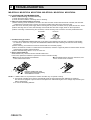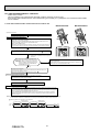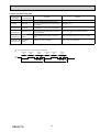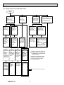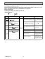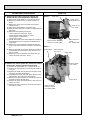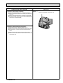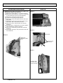
1
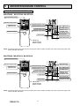
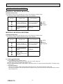
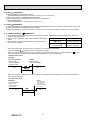
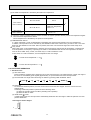
Revision A:
• MS-GF50VAMS-GF80VA-
SPLIT-TYPE AIR CONDITIONERS
E1
E1
, MS-GF60VA- E1 and
have been added.
Please void OBH621.
INDOOR UNIT
SERVICE MANUAL
No. OBH621
REVISED EDITION-A
Models
MS-GF20VA
MS-GF25VA
MS-GF35VA
MS-GF50VA
MS-GF60VA
MS-GF80VA
-
E1
-
E1
-
E1
-
E1
-
E1
-
E1
Outdoor unit service manual
MU-GF·VA Series (OBH622)
CONTENTS
1. TECHNICAL CHANGES ···································
2
2. PART NAMES AND FUNCTIONS ·····················
3
3. SPECIFICATION ················································
5
4. NOISE CRITERIA CURVES ······························
6
5. OUTLINES AND DIMENSIONS ························
8
6. WIRING DIAGRAM············································
9
7. REFRIGERANT SYSTEM DIAGRAM ·············10
8. SERVICE FUNCTIONS ···································
12
9. MICROPROCESSOR CONTROL ···················
14
10. TROUBLESHOOTING ·····································
21
11. DISASSEMBLY INSTRUCTIONS ····················
35
PARTS CATALOG (OBB621)
NOTE:
RoHS compliant products have <G> mark on the spec name plate.
Use the specif ed refrigerant only
Never use any refrigerant other than that specified.
Doing so may cause a burst, an explosion, or fire when the unit is being used, serviced, or disposed of.
Correct refrigerant is specified in the manuals and on the spec labels provided with our products.
We will not be held responsible for mechanical failure, system malfunction, unit breakdown or accidents caused by
failure to follow the instructions.
<Preparation before the repair service>
Prepare the proper tools.
Prepare the proper protectors.
Provide adequate ventilation.
After stopping the operation of the air conditioner, turn off the power-supply breaker and remove the power plug.
Discharge the capacitor before the work involving the electric parts.
<Precautions during the repair service>
Do not perform the work involving the electric parts with wet hands.
Do not pour water into the electric parts.
Do not touch the refrigerant.
Do not touch the hot or cold areas in the refrigeration cycle.
When the repair or the inspection of the circuit needs to be done without turning off the power, exercise great caution not to
touch the live parts.
Revision A:
• MS-GF50VA-
1
E1
, MS-GF60VA-
E1
and MS-GF80VA-
E1
have been added.
TECHNICAL CHANGES
MS-GF20VA MS-GF25VA MS-GF35VA -
E1
E1
E1
1. New model
MS-GF50VA MS-GF60VA MS-GF80VA -
E1
E1
E1
1. New model
OBH621A
2
2
PART NAMES AND FUNCTIONS
MS-GF20VA MS-GF25VA MS-GF35VA
Front panel
Air f lter
(Nano platinum f lter)
Air cleaning f lter
(Electrostatic anti-allergy
enzyme f lter, option)
Air inlet
Remote controller
Air outlet
Heat exchanger
Horizontal vane
Display section
Remote control receiving section
Operation indicator lamp
Emergency operation switch (E.O. SW)
ACCESSORIES
Model
MS-GF20VA
MS-GF25VA
MS-GF35VA
Installation plate
Installation plate f xing screw 4 × 25 mm
Remote controller holder
Fixing screw for 3.5 × 16 mm (Black)
Battery (AAA) for remote controller
Wireless remote controller
Felt tape (For left or left-rear piping)
1
5
1
2
2
1
1
OBH621A
3
MS-GF50VA MS-GF60VA MS-GF80VA
Front panel
Air f lter
(Nano platinum f lter)
Air cleaning f lter
(Electrostatic anti-allergy
enzyme f lter, option)
Air inlet
Remote controller
Air outlet
Heat exchanger
Horizontal vane
Display section
Operation indicator lamp
Emergency operation switch
(E.O.SW)
Remote control receiving section
ACCESSORIES
OBH621A
Model
MS-GF50VA
MS-GF60VA
MS-GF80VA
Installation plate
Installation plate f xing screw 4 × 25 mm
Remote controller holder
Fixing screw for 3.5 × 16 mm (Black)
Battery (AAA) for remote controller
Wireless remote controller
Felt tape (For left or left-rear piping)
1
7
1
2
2
1
1
4
3
SPECIFICATION
MS-GF20VA MS-GF25VA MS-GF35VA MS-GF50VA MS-GF60VA MS-GF80VA
Fan
Electrical
motor
data
Indoor model
Function
Cooling
Power supply
Single phase 230 V, 50 Hz
Running current
A
0.20
0.22
0.30
0.42
Power input
W
35
43
39
51
Model
RC4V18-FA
Current
A
Dimensions W × H × D
mm
798 x 295 x 232
kg
9
Weight
RC0J56-AF
0.22
0.20
Airf ow
Sound level
Fan speed
0.42
1,100 x 325 x 238
16
5
Air direction
Special remarks
0.30
Super High (POWERFUL)
558
624
1,086
1,086
1,206
High
474
558
870
942
1,086
Med.
3
m /h
378
396
762
822
978
Low
246
288
642
714
882
Super High (POWERFUL)
40
44
45
48
50
High
36
40
42
45
47
31
33
38
41
43
Med.
dB (A)
Low
Super High (POWERFUL)
High
Med.
rpm
Low
25
26
34
37
39
1,000
1,100
1,100
1,100
1,200
880
1,000
920
980
1,100
740
770
800
880
1,010
540
610
720
790
930
Fan speed regulator
Remote controller model
NOTE: Test conditions are based on ISO 5151.
Cooling: Indoor
Dry-bulb temperature 27
Outdoor Dry-bulb temperature 35
Indoor-Outdoor piping length: 5 m
OBH621A
4
KM12A
Wet-bulb temperature 19
Wet-bulb temperature 24
5
KM12B
4
NOISE CRITERIA CURVES
MS-GF20VA
MS-GF25VA
OCTAVE BAND SOUND PRESSURE LEVEL, 0dB re 0.0002 MICRO BAR
Super High
SPL(dB(A))
COOLING
LINE
Super High
90
80
70
NC-70
60
NC-60
50
NC-50
40
NC-40
30
NC-30
20
NC-20
NC-10
10
63
125
250
500
1000
FAN SPEED FUNCTION
40
2000
4000
OCTAVE BAND SOUND PRESSURE LEVEL, 0dB re 0.0002 MICRO BAR
FAN SPEED FUNCTION
8000
BAND CENTER FREQUENCIES, Hz
SPL(dB(A))
LINE
40
COOLING
90
80
70
NC-70
60
NC-60
50
NC-50
40
NC-40
30
NC-30
20
NC-20
NC-10
10
63
125
250
500
1000
2000
4000
8000
BAND CENTER FREQUENCIES, Hz
MS-GF35VA
FAN SPEED FUNCTION
OCTAVE BAND SOUND PRESSURE LEVEL, 0dB re 0.0002 MICRO BAR
Super High
SPL(dB(A))
COOLING
LINE
44
90
80
70
NC-70
Test conditions
Cooling: Dry-bulb temperature 27 °C
Wet-bulb temperature 19 °C
60
NC-60
50
NC-50
40
INDOOR UNIT
NC-40
1m
30
NC-30
0.8m
20
NC-20
NC-10
10
63
125
250
500
1000
2000
4000
MICROPHONE
8000
BAND CENTER FREQUENCIES, Hz
OBH621A
6
WALL
MS-GF50VA
MS-GF60VA
FAN SPEED FUNCTION
SPL(dB(A))
FAN SPEED FUNCTION
LINE
Super High
45
COOLING
90
OCTAVE BAND SOUND PRESSURE LEVEL, 0dB re 0.0002 MICRO BAR
OCTAVE BAND SOUND PRESSURE LEVEL, 0dB re 0.0002 MICRO BAR
Super High
80
70
NC-70
60
NC-60
50
NC-50
40
NC-40
30
NC-30
20
NC-20
NC-10
10
63
125
250
500
1000
2000
4000
8000
MS-GF80VA
OCTAVE BAND SOUND PRESSURE LEVEL, 0dB re 0.0002 MICRO BAR
Super High
SPL(dB(A))
COOLING
LINE
50
90
80
70
NC-70
60
NC-60
50
NC-50
40
NC-40
30
NC-30
20
NC-20
NC-10
10
63
125
250
500
1000
2000
4000
8000
BAND CENTER FREQUENCIES, Hz
OBH621A
7
LINE
48
90
80
70
NC-70
60
NC-60
50
NC-50
40
NC-40
30
NC-30
20
NC-20
NC-10
10
63
125
250
500
1000
2000
4000
BAND CENTER FREQUENCIES, Hz
BAND CENTER FREQUENCIES, Hz
FAN SPEED FUNCTION
SPL(dB(A))
COOLING
8000
5
OUTLINES AND DIMENSIONS
Unit: mm
MS-GF20VA MS-GF25VA MS-GF35VA
41
155
61
232
5
21.5
211.5
254
212.5
6.5
11×20 Oblong hole
80
225
155
338
3
42
798
785
225
231.5
253
11×26 Oblong hole
80
Installation plate
315
84
Wall hole ø65
Air in
Indoor unit
Installation plate
58
619
42
130
112
Insulation
Liquid line
Gas line
Drain hose
Piping
42
43
159
Air out
50
56
Drain hose
107
19
ø35 O.D
ø7 - 0.5 m (Flared connection ø6.35)
ø9.52 - 0.43 m (Flared connection: ø9.52)
Insulation ø28 O.D Connected part ø16 O.D
MS-GF50VA MS-GF60VA MS-GF80VA
11×26 Oblong hole
129
Installation plate
225
11×20 Oblong hole
225
110
238.5
258.5
280
5
Indoor unit
238
49.5
500.5
199.5
Air in
199.5
Installation plate
3
44
281
239.5
1100
1090
Unit: mm
110.5
439.5
Wall hole Ø75
Piping
181
65
( 70° )
19
Air out
125
160
184
3
12
843
100
65
76
Drain hose
MS-GF60VA
63
30
65
65
OBH621A
Ø50 O.D
Ø9.52 - 0.5m (Flared connection Ø6.35)
Ø12 - 0.43m (Flared connection Ø12.7)
Inslation Ø28 Connected part Ø16 O.D
Piping
Insulation
Liquid line
Gas line
Drain hose
Insulation
Liquid line
Gas line
Drain hose
Ø50 O.D
Ø9.52 - 0.5m (Flared connection Ø6.35)
Ø12 - 0.43m (Flared connection Ø15.88)
Inslation Ø28 Connected part Ø16 O.D
MS-GF80VA
MS-GF50VA
Piping
Piping
63
159
58
67
325
210
5
63
8
21.5
50
Insulation
Liquid line
Gas line
Drain hose
Ø50 O.D
Ø9.52 - 0.5m (Flared connection Ø9.52)
Ø12 - 0.43m (Flared connection Ø15.88)
Inslation Ø28 Connected part Ø16 O.D
45
45
56
69
69
56
100
8
295
Piping
6
WIRING DIAGRAM
MS-GF20VA MS-GF25VA MS-GF35VA
MS-GF50VA MS-GF60VA MS-GF80VA
OBH621A
9
7
REFRIGERANT SYSTEM DIAGRAM
MS-GF20VA MS-GF25VA
Unit: mm
Refrigerant pipe 9.52
(with heat insulator)
Indoor
heat
exchanger
Indoor coil
thermistor
RT12
Flared connection
Room temperature
thermistor
RT11
Flared connection
Refrigerant pipe 6.35
(with heat insulator)
Refrigerant flow in cooling
MS-GF35VA
Refrigerant pipe 9.52
(with heat insulator)
Indoor
heat
exchanger
Indoor coil
thermistor
RT12
Flared connection
Room temperature
thermistor
RT11
Flared connection
Refrigerant pipe 6.35
(with heat insulator)
Refrigerant flow in cooling
OBH621A
10
MS-GF50VA MS-GF60VA MS-GF80VA
Unit: mm
Refrigerant pipe ø12.7 (MS-GF50VA)
ø15.88 (MS-GF60/80VA)
(with heat insulator)
Indoor
heat
exchanger
Indoor coil
thermistor
RT12
Flared connection
Room temperature
thermistor
RT11
Flared connection
Refrigerant pipe ø6.35 (MS-GF50/60VA)
ø9.52 (MS-GF80VA)
(with heat insulator)
Refrigerant flow in cooling
OBH621A
11
8
SERVICE FUNCTIONS
MS-GF20VA MS-GF25VA MS-GF35VA MS-GF50VA MS-GF60VA MS-GF80VA
8-1. TIMER SHORT MODE
For service, the following set time can be shortened by short circuit of JPG and JPS on the electronic control P.C. board.
(Refer to 10-7.)
Set time: 3 minutes → 3 seconds (It takes 3 minutes for the compressor to start operation. However, the starting time is
shortened by short circuit of JPG and JPS.)
8-2. P.C. BOARD MODIFICATION FOR INDIVIDUAL OPERATION
A maximum of 4 indoor units with wireless remote controllers can be used in a room.
In this case, to operate each indoor unit individually by each remote controller, P.C. boards of remote controller must be
modified according to the number of the indoor unit.
How to modify the remote controller P.C. board
Remove batteries before modification.
The board has a print as shown below:
NOTE: For modification, take out
the batteries and press
the OPERATE/STOP (ON/
OFF) button 2 or 3 times at
first.
After modification, put back
the batteries then press the
RESET button.
J1
J2
The P.C. board has the print “J1” and “J2”. Solder “J1” and “J2” according to the number of indoor unit as shown in Table 1.
After modification, press the RESET button.
Table 1
1 unit operation
2 units operation
3 units operation
4 units operation
No. 1 unit
No modif cation
Same as at left
Same as at left
Same as at left
No. 2 unit
—
Solder J1
Same as at left
Same as at left
No. 3 unit
—
—
Solder J2
Same as at left
No. 4 unit
—
—
—
Solder both J1 and J2
How to set the remote controller exclusively for particular indoor unit
After you turn the breaker ON, the first remote controller that sends the signal to the indoor unit will be regarded as the remote
controller for the indoor unit.
The indoor unit will only accept the signal from the remote controller that has been assigned to the indoor unit once they are set.
The setting will be cancelled if the breaker is turned OFF, or the power supply is shut down.
Please conduct the above setting once again after the power has restored.
OBH621A
12
8-3. AUTO RESTART FUNCTION
When the indoor unit is controlled with the remote controller, the operation mode, the set temperature, and the fan speed
are memorized by the indoor electronic control P.C. board. “AUTO RESTART FUNCTION” automatically starts operation
in the same mode just before the shutoff of the main power.
Operation
If the main power has been cut, the operation settings remain.
After the power is restored, the unit restarts automatically according to the memory.
(However, it takes at least 3 minutes for the compressor to start running.)
How to disable “AUTO RESTART FUNCTION”
Turn off the main power for the unit.
Solder the jumper wire to JR07 on the indoor electronic control P.C. board (MS-GF20/25/35VA).
Cut the jumper wire to JR77 on the indoor electronic control P.C. board (MS-GF50/60/80VA). (Refer to 10-7.)
MS-GF20/25/35VA
JR77
CN10A
CN151 CN152 CN111
CN112
CN112 CN111
CN10A
CN151
Indoor electronic
control P.C. board
MS-GF50/60/80VA
JR07
Indoor electronic
control P.C. board
NOTE:
• The operation settings are memorized when 10 seconds have passed after the indoor unit was operated with the remote
controller.
• If main power is turned OFF or a power failure occurs while AUTO START/STOP timer is active, the timer setting is cancelled.
• If the unit has been off with the remote controller before power failure, the auto restart function does not work as the
power button of the remote controller is OFF.
• To prevent breaker OFF due to the rush of starting current, systematize other home appliance not to turn ON at the same
time.
• When some air conditioners are connected to the same supply system, if they are operated before power failure, the
starting current of all the compressors may flow simultaneously at restart.
Therefore, the special counter-measures are required to prevent the main voltage-drop or the rush of the starting current
by adding to the system that allows the units to start one by one.
OBH621A
13
9
MICROPROCESSOR CONTROL
WIRELESS REMOTE CONTROLLER
MS-GF20VA MS-GF25VA MS-GF35VA
Signal transmitting section
Operation display section
OPERATE/STOP
(ON/OFF) button
FAN SPEED CONTROL button
OFF-TIMER button
OPERATION SELECT button
ON-TIMER button
ECONO COOL button
Temperature buttons
TIME SET buttons
FORWARD button
BACKWARD button
POWERFUL COOL button
CLOCK button
RESET button
VANE CONTROL button
Indication of
remote controller
model is on back
NOTE: Last setting will be stored after the unit is turned OFF with the remote controller. Indoor unit receives the signal of the
remote controller with beeps.
MS-GF50VA MS-GF60VA MS-GF80VA
Signal transmitting section
WIDE VANE button
(Vertical vane button)
Operation display section
OPERATE/STOP
(ON/OFF) button
FAN SPEED CONTROL button
OFF-TIMER button
OPERATION SELECT button
ON-TIMER button
ECONO COOL button
Temperature buttons
POWERFUL COOL button
LONG button
LONG
TIME SET buttons
FORWARD button
BACKWARD button
CLOCK SET button
RESET button
VANE CONTROL button
(Horizontal vane button)
Indication of
remote controller
model is on back
NOTE: Last setting will be stored after the unit is turned OFF with the remote controller. Indoor unit receives the signal of the
remote controller with beeps.
OBH621A
14
INDOOR UNIT DISPLAY SECTION
MS-GF20VA MS-GF25VA MS-GF35VA
Operation Indicator lamp
The operation indicator at the right side of the indoor unit indicates the operation state.
•The following indication applies regardless of shape of the indication.
Indication
Operation state
The unit is operating to
reach the set temperature
Room temperature
About 2°C or more away
from set temperature
Lighted
Blinking
Not lighted
The room temperature is
approaching the set temperature
About 1 to 2°C from set
temperature
MS-GF50VA MS-GF60VA MS-GF80VA
Operation Indicator lamp
The operation indicator at the right side of the indoor unit indicates the operation state.
•The following indication applies regardless of shape of the indication.
Indication
Operation state
Room temperature
Lighted
Blinking
The unit is operating to
reach the set temperature
About 2°C or more away
from set temperature
The room temperature is
approaching the set temperature
About 1 to 2°C from set
temperature
Standby mode
(Only during multi system
operation)
Not lighted
-
9-1. COOL ( ) OPERATION
(1) Press OPERATE/STOP (ON/OFF) button.
OPERATION INDICATOR lamp of the indoor unit turns on with a beep tone.
(2) Select COOL mode with OPERATION SELECT button.
(3) Press TEMPERATURE buttons (TOO WARM or TOO COOL button) to select the desired temperature. The setting range
is 16 - 31°C.
1. Coil frost prevention
When the temperature of indoor heat exchanger becomes too low, the coil frost prevention mode works.
The indoor fan operates at the set speed and the compressor stops. This mode continues until the temperature of indoor
heat exchanger rises.
OBH621A
15
9-2. DRY ( ) OPERATION
(1) Press OPERATE/STOP (ON/OFF) button.
OPERATION INDICATOR lamp of the indoor unit turns on with a beep tone.
(2) Select DRY mode with OPERATION SELECT button.
(3) The set temperature is determined from the initial room temperature.
1. Coil frost prevention
Coil frost prevention is as same as COOL mode. (9-1.1.)
9-3. FAN ( )OPERATION
(1) Press OPERATE/STOP (ON/OFF) button. OPERATION INDICATOR lamp of the indoor unit turns ON with a beep tone.
(2) Select FAN mode with OPERATION SELECT button.
(3) Select the desired fan speed. When AUTO, it becomes Low. Only indoor fan operates. Outdoor unit does not operate.
9-4. “I FEEL CONTROL” ( ) OPERATION
(1) Press OPERATE/STOP (ON/OFF) button on the remote controller. OPERATION INDICATOR lamp of the indoor unit
turns ON with a beep tone.
(2) Select “I FEEL CONTROL” mode with the OPERATION SELECT
Mode
Initial room temperature
button.
COOL mode of
25 or more
(3) The operation mode is determined by the room temperature at
"I FEEL CONTROL"
start-up of the operation.
more than 13 ,
DRY mode of
"I FEEL CONTROL"
less than 25
•
•
Once the mode is fixed, the mode does not change by room temperature afterwards.
) operation, mode is determined as follows:
Under ON-TIMER (
When the system is stopped by the remote controller, and restarted within 2 hours in “I FEEL CONTROL” (
the system operates in previous mode automatically regardless of the room temperature.
) mode,
Operation timer chart
Example
Previous operation
COOL mode of
“I FEEL CONTROL”
or COOL mode
Restart
COOL mode of
“I FEEL CONTROL”
When the system is restarted after 2 hours and more, the operation mode is determined by the room temperature at
start-up of the operation.
Operation time chart
Example
Previous operation
COOL mode of
“I FEEL CONTROL”
or COOL mode
OBH621A
Restart
COOL or DRY mode of
“I FEEL CONTROL” that
determined by room
temperature at start-up
of the operation.
16
(4) The initial set temperature is decided by the initial room temperature.
Initial room temperature
Mode
Initial set temperature
26 °C or more
24 °C
COOL mode of
“I FEEL CONTROL”
1
Initial room temperature
minus 2 °C
25 °C to 26 °C
DRY mode of
“I FEEL CONTROL”
Initial room temperature
minus 2 °C
more than 13 °C, less than 25 °C
1 When the system is restarted with the remote controller, the system operates with the previous set temperature regardless of the room temperature at restart.
The set temperature is calculated by the previous set temperature.
(5) TEMPERATURE buttons
In “I FEEL CONTROL” mode, set temperature is decided by the microprocessor based on the room temperature.
In addition, set temperature can be controlled by TOO WARM or TOO COOL buttons when you feel too cool or too warm.
Each time TOO WARM or TOO COOL button is pressed, the indoor unit receives the signal and emits a beep tone.
Fuzzy control
When TOO COOL or TOO WARM button is pressed, the microprocessor changes the set temperature, considering the
room temperature, the frequency of pressing TOO COOL or TOO WARM button and the user’s preference to heat or
cold. So this is called “Fuzzy control”, and works only in “I FEEL CONTROL” mode.
In DRY mode of “I FEEL CONTROL”, the set temperature does not change.
… To raise the set temperature 1 ~ 2
… To lower the set temperature 1 ~ 2
9-5. AUTO VANE OPERATION
1. Horizontal vane
(1) Vane motor drive
These models are equipped with a stepping motor for the horizontal vane. The rotating direction, speed, and angle of
the motor are controlled by pulse signals (approximately 12 V) transmitted from indoor microprocessor.
(2) The horizontal vane angle and mode change as follows by pressing VANE CONTROL button.
AUTO
1
2
3
4
5
SWING
(3) Positioning
To confirm the standard position, the vane moves until it touches the vane stopper. Then the vane is set to the
selected angle.
Confirming of standard position is performed in the following cases:
(a) When the operation starts or finishes (including timer operation).
(b) When the test run starts.
(4) VANE AUTO ( ) mode
In VANE AUTO mode, the microprocessor automatically determines the vane angle to make the optimum room temperature distribution.
Vane angle is fixed to Angle 1.
1
OBH621A
17
(5) STOP (operation OFF) and ON TIMER standby
In the following cases, the horizontal vane returns to the closed position.
(a) When OPERATE/STOP (ON/OFF) button is pressed (POWER OFF).
(b) When the operation is stopped by the emergency operation.
(c) When ON TIMER is ON standby.
(6) Dew prevention
During COOL or DRY operation with the vane angle at Angle 4 or 5 when the compressor cumulative operation time
exceeds 1 hour, the vane angle automatically changes to Angle 1 for dew prevention.
(7) SWING ( ) mode
By selecting SWING mode with VANE CONTROL button, the horizontal vane swings vertically.
(8) ECONO COOL ( ) operation (ECONOmical operation)
When ECONO COOL button is pressed in COOL mode, set temperature is automatically set 2°C higher.
Also the horizontal vane swings in various cycles.
SWING operation makes you feel cooler than set temperature. So, even though the set temperature is higher, the
air conditioner can keep comfort. As a result, energy can be saved.
To cancel this operation, select a different mode or press one of the following buttons in ECONO COOL operation:
ECONO COOL, VANE CONTROL or POWERFUL button.
(9) POWERFUL (
) operation
The air conditioner automatically adjusts the fan speed and the set temperature, and operates the POWERFUL mode.
The POWERFUL mode is cancelled automatically 15 minutes after operation starts. To cancel this operation manually, select a different mode or press one of the following buttons: POWERFUL, OPERATE/STOP (ON/OFF), ECONO
COOL, or FAN, SPEED CONTROL button.
(10) LONG MODE (
) (MS-GF50/60/80VA)
By pressing LONG button indoor fan speed becomes faster than setting fan speed on the remote controller, and the
horizontal vane moves to the position for LONG mode. The remote controller displays “
”. To cancel this operation, press one of the following buttons: LONG, VANE CONTROL, or ECONO COOL (during cool mode). In the following example, the vertical vane is set to
(front.).
2. Vertical vane (MS-GF50/60/80VA)
(1) Vane motor drive
These models are equipped with a stepping motor for the vertical vane. The rotating direction, speed, and angle of
the motor are controlled by pulse signals (approximate 12 V) transmitted from microprocessor.
(2) The vertical vane angle and mode change as follows by pressing WIDE VANE CONTROL button.
(3) Positioning
To confirm the standard position, the vane moves until it touches the vane stopper. Then the vane is set to the selected angle.
1
2
3
4
5
6
(SWING)
Confirming of standard position is performed in the following cases:
(a) OPERATE/STOP (ON/OFF) button is pressed (POWER ON).
(b) SWING is started.
(4) SWING ( ) MODE
By selecting SWING mode with WIDE VANE button, the vertical vane swings horizontally. The remote controller displays
“ ”. Swing mode is cancelled when WIDE VANE button is pressed once again.
(5) WIDE MODE ( )
By selecting WIDE mode with WIDE VANE button, indoor fan speed becomes faster than setting fan speed on the
remote controller ( ). The remote controller displays “ ”.
Indoor fan speed becomes faster than setting fan speed on the remote controller even when
or
is selected.
OBH621A
18
9-6. TIMER OPERATION
1. How to set the time
(1) Check that the current time is set correctly.
NOTE: Timer operation will not work without setting the current time. Initially “0:00” blinks at the current time display
of TIME MONITOR, so set the current time correctly with CLOCK button.
How to set the current time
(a) Press the CLOCK button.
(b) Press the TIME SET buttons (
and
) to set the current time.
• Each time FORWARD button (
) is pressed, the set time increases by 1 minute, and each time BACKWARD
button (
) is pressed, the set time decreases by 1 minute.
• Pressing those buttons longer, the set time increases/decreases by 10 minutes.
(c) Press the CLOCK button.
(2) Press OPERATE/STOP (ON/OFF) button to start the air conditioner.
(3) Set the time of timer.
ON timer setting
) during operation.
(a) Press ON TIMER button(
(b) Set the time of the timer using TIME SET buttons (
and
).
OFF timer setting
(a) Press OFF TIMER button (
) during operation.
(b) Set the time of the timer using TIME SET buttons (
and
).
Each time FORWARD button (
) is pressed, the set time increases by 10 minutes: each time BACKWARD button (
) is pressed, the set time decreases by 10 minutes.
2. To release the timer
To release ON timer, press ON TIMER button (
).
To release OFF timer, press OFF TIMER button(
).
TIMER is cancelled and the display of set time disappears.
PROGRAM TIMER
• OFF timer and ON timer can be used in combination. The timer of the set time that is reached first will operate first.
• “ ” and “ ” display shows the order of OFF timer and ON timer operation.
(Example 1) The current time is 8:00 PM.
The unit turns off at 11:00 PM, and on at 6:00 AM.
(Example 2) The current time is 11:00 AM.
The unit turns on at 5:00 PM, and off at 9:00 PM.
NOTE: If the main power is turned OFF or a power failure occurs while ON/OFF timer is active, the timer setting is cancelled. As these models are equipped with an auto restart function, the air conditioner starts operating with timer
cancelled when power is restored.
OBH621A
19
9-7. EMERGENCY/TEST OPERATION
In case of test run operation or emergency operation, use
EMERGENCY OPERATION switch on the right side of the indoor unit.
Emergency operation is available when the remote controller is missing, has failed or the batteries of the remote controller run down. The
unit will start and OPERATION INDICATOR lamp will light.
The first 30 minutes of operation is the test run operation. This operation is for servicing. The indoor fan runs at High speed and the temperature control does not work.
After 30 minutes of test run operation, the system shifts to
EMERGENCY COOL MODE with a set temperature of 24°C. The fan
speed shifts to Med.
The coil frost prevention works even in the test run or the emergency
operation.
In the test run or emergency operation, the horizontal vane operates in
VANE AUTO ( ) mode.
Emergency operation continues until EMERGENCY OPERATION
switch is pressed again or the unit receives any signal from the remote
controller. In case of latter, normal operation will start.
Operation mode
Set temperature
Fan speed
Horizontal vane
COOL
24°C
Med.
Auto
The operation mode is indicated by the
Operation Indicator lamp as following
Operation Indicator lamp
EMERGENCY COOL
↓
STOP
Lighted
Not lighted
NOTE: Do not press EMERGENCY OPERATION switch during normal operation.
Emergency
operation switch
(E.O. SW)
9-8. 3-MINUTE TIME DELAY OPERATION
When the system turns OFF, compressor will not restart for 3 minutes as 3-minute time delay function operates to protect
compressor from overload.
OBH621A
20
10
TROUBLESHOOTING
MS-GF20VA MS-GF25VA MS-GF35VA MS-GF50VA MS-GF60VA MS-GF80VA
10-1. CAUTIONS ON TROUBLESHOOTING
1. Before troubleshooting, check the following
1) Check the power supply voltage.
2) Check the indoor/outdoor connecting wire for miswiring.
2. Take care of the following during servicing
1) Before servicing the air conditioner, be sure to turn OFF the main unit first with the remote controller, and then after
confirming the horizontal vane is closed, turn OFF the breaker and/or disconnect the power plug.
2) Be sure to turn OFF the power supply before removing the front panel, the cabinet, the top panel, and the P.C. board.
3) When removing the P.C. board, hold the edge of the board with care NOT to apply stress on the components.
4) When connecting or disconnecting the connectors, hold the housing of the connector. DO NOT pull the lead wires.
<Incorrect>
<Correct>
Lead wiring
Housing point
3. Troubleshooting procedure
1) Check if the OPERATION INDICATOR lamp on the indoor unit is flashing ON and OFF to indicate an abnormality.
To make sure, check how many times the OPERATION INDICATOR lamp is flashing ON and OFF before starting
service work.
2) Before servicing, check that the connector and terminal are connected properly.
3) When the electronic control P.C. board seems to be defective, check the copper foil pattern for disconnection and the
components for bursting and discoloration.
4) When troubleshooting, Refer to 10-2, 10-3 and 10-4.
4. How to replace batteries
Weak batteries may cause the remote controller malfunction.
In this case, replace the batteries to operate the remote controller normally.
Remove the front lid and insert batteries.
Then reattach the front lid.
Press RESET button with a thin instrument, and
then use the remote controller.
Insert the negative pole of the
batteries first. Check if the polarity
of the batteries is correct.
RESET button
NOTE: 1. If RESET button is not pressed, the remote controller may not operate correctly.
2. This remote controller has a circuit to automatically reset the microcomputer when batteries are replaced.
This function is equipped to prevent the microcomputer from malfunctioning due to the voltage drop caused by the
battery replacement.
3. Do not use the leaking batteries.
OBH621A
21
10-2. FAILURE MODE RECALL FUNCTION
Outline of the function
This air conditioner can memorize the abnormal condition which has occurred once.
Even though LED indication listed on the troubleshooting check table (10-4.) disappears, the memorized failure details
can be recalled.
1. Flow chart of failure mode recall function for the indoor unit
MS-GF20/25/35VA
MS-GF50/60/80VA
Operational procedure
The cause of abnormality cannot be found because the abnormality does not recur.
Setting up the failure mode recall function
Turn ON the power supply.
<Preparation of the remote controller>
While pressing both OPERATION SELECT button and TOO COOL button on the
remote controller at the same time, press RESET button.
First, release RESET button.
Hold down the other two buttons for another 3 seconds. Conf rm that the indicators on
the LCD screen shown in the right f gure are all displayed. Then release the buttons.
Press OPERATE/STOP (ON/OFF) button of the remote controller (the set temperature is
displayed) with the remote controller headed towards the indoor unit. 1
1 Regardless of normal or abnormal condition,
a short beep is emitted once the signal is
received.
Does upper lamp of OPERATION INDICATOR
lamp on the indoor unit blink at the interval of 0.5
seconds?
Blinks: Either indoor or outdoor unit is abnormal.
Beep is emitted at the same timing as the
blinking of upper lamp of OPERATION
INDICATOR lamp. 2
Yes
(Blinks)
Indoor unit is normal.
But the outdoor unit might be abnormal because there are some abnormalities that can not be recalled with this way.
No
(OFF)
The indoor unit is abnormal.
Check the blinking pattern, and conf rm the abnormal point with the indoor unit
failure mode table. (Refer to 10-2.2)
Make sure to check at least 2 consecutive blinking cycles.
2
Releasing the failure mode recall function
Release the failure mode recall function by the following procedures.
Turn OFF the power supply and turn it ON again.
Press RESET button of the remote controller.
Repair the defective parts.
Deleting the memorized abnormal condition
After repairing the unit, recall the failure mode again according to "Setting up the failure mode recall
function" mentioned above.
Press OPERATE/STOP (ON/OFF) button of the remote controller (the set temperature is displayed)
with the remote controller headed towards the indoor unit.
Press EMERGENCY OPERATION switch so that the memorized abnormal condition is deleted.
Release the failure mode recall function according to "Releasing the failure mode recall function"
mentioned above.
NOTE: 1. Make sure to release the failure mode recall function once it is set up, otherwise the unit cannot operate properly.
2. If the abnormal condition is not deleted from the memory, the last abnormal condition is kept memorized.
2. Blinking pattern when the indoor unit is abnormal:
Blinking at 0.52.5-second OFF second interval
ON
OFF
Beeps
Repeated cycle
OBH621A
Blinking at 0.52.5-second OFF second interval
Beeps
Repeated cycle
Beeps
Repeated cycle
22
2. Indoor unit failure mode table
Upper lamp of OPAbnormal point
ERATION INDICA(Failure mode)
TOR lamp
Not lighted
Normal
Condition
Remedy
—
The room temperature thermistor short or
1-time f ash every Room temperature
open circuit is detected every 8 seconds dur0.5-second
thermistor
ing operation.
Indoor coil
2-time f ash
The indoor coil thermistor short or open circuit
2.5-second OFF
is detected every 8 seconds during operation.
thermistor
The rotational frequency feedback signal is
11-time f ash
Indoor fan motor
not emitted for 12 seconds after the indoor fan
2.5-second OFF
motor is operated.
It cannot properly read data in the nonvolatile
12-time f ash
Indoor control
memory of the indoor electronic control P.C.
2.5-second OFF
system
board.
14-time f ash 1
2.5-second OFF
Refrigerant
circuit
Refer to 10-4. No.4 "Condition".
—
Refer to the characteristics of the room temperature
thermistor (10-7.).
Refer to the characteristics of the indoor coil thermistor
(10-7.).
Refer to 10-6.
"Check of indoor fan motor".
Replace the indoor electronic control P.C. board.
Refer to 10-4. No.4 "Remedy".
NOTE: Blinking patterns of this mode differ from the ones of TROUBLESHOOTING CHECK TABLE (10-4.).
1. A blinking pattern when "14-time flash" is displayed :
2.5-second
OFF
3.0-second
ON
14-time
flash
2.5-second
OFF
3.0-second
ON
14-time
flash
ON
OFF
Beeps
Repeated cycle
OBH621A
Beeps
Repeated cycle
23
10-3. INSTRUCTION OF TROUBLESHOOTING
Start
Indoor unit operates.
Outdoor unit
does not operate.
Outdoor unit
operates only
in Test Run
operation.
Outdoor unit
does not
operate even
in "Test run
operation".
Check room
temperature
thermistor.
Refer to 10-7.
"Test point
diagram and
voltage".
1. Check
the wiring
diagram of
the outdoor
unit.
2. Check the
outdoor
fuse.
Check the
indoor fuse
(F11), outdoor
fuse (F) and
the compressor contactor
(52C).
Upper lamp
2-time f ash
Cause:
Indoor unit
• Trouble
of room
temperature
/ indoor coil
thermistor
Upper lamp
3-time f ash
Cause:
Indoor unit
• Trouble of
indoor fan
motor
Upper lamp
4-time f ash
Cause:
Indoor unit
• Trouble
of indoor
unit control
system
Upper lamp
14-time f ash
Cause:
Outdoor unit
• Troubles
regarding
refrigerant
circuit
Check room
temperature
thermistor
and indoor
coil thermistor. Refer to
10-7. "Test
point diagram
and voltage".
Refer to
10-6.
"Check of
indoor fan
motor".
Replace the
indoor electronic control
P.C. board.
Refer to 10-4
No. 4 "Remedy".
OBH621A
Indoor unit does
not receive the
signal from remote controller.
Indoor and
outdoor unit
do not operate.
OPERATION INDICATOR
lamp on the indoor unit is
f ashing ON and OFF.
Indoor unit
operates, when
EMERGENCY
OPERATION
switch is pressed.
Indoor unit does
not operate, when
EMERGENCY
OPERATION
switch is pressed.
Refer to 10-6.
"Check of remote
controller and
indoor electronic
control P.C. board".
1. Check indoor/outdoor connecting wire.
(Check if the power is
supplied to the indoor
unit.)
2. Check the outdoor fuse (F).
3. Refer to 10-6. "Check
of indoor P.C. board
and indoor fan motor".
"Test Run operation" means the
operation within 30 minutes after EMERGENCY OPERATION
switch is pressed.
If blinking of OPERATION INDICATOR lamp cannot be checked,
it can be checked with failure
mode recall function.
Refer to outdoor unit service manual.
24
10-4. TROUBLESHOOTING CHECK TABLE
Before taking measures, make sure that the symptom reappears for accurate troubleshooting.
When the indoor unit has started operation and detected an abnormality of the following condition (the first detection after the
power ON), the indoor fan motor turns OFF and OPERATION INDICATOR lamp flashes.
Operation Indicator lamp
The operation indicator lamp is at the right side of the indoor unit.
•The following indication applies regardless of shape of the indication.
OPERATION INDICATOR
Lighted
Blinking
Not lighted
No.
Abnormal
point
Indoor coil
thermistor
1
Room temperature
thermistor
Operation indicator lamp
Symptom
Condition
Upper lamp f ashes.
2-time f ash
2.5-second OFF
Remedy
The indoor coil or the room temperature thermistor is short or open circuit.
• Refer to the characteristics of
indoor coil thermistor, and the
room temperature thermistor
(10-7.).
The rotational frequency feedback signal is
not emitted during the indoor fan operation.
• Refer to 10-6. "Check of indoor fan motor".
It cannot properly read data in the nonvolatile
memory of the indoor electronic control P.C.
board.
• Replace the indoor electronic
control P.C. board.
The unit has been pumped down for a long
time.
• Check the stop valve.
The refrigerant amount is low.
• Check the connections and the
refrigerant amount for any leakage.
Upper lamp f ashes.
3-time f ash
2
Indoor fan
motor
2.5-second OFF
Upper lamp f ashes.
4-time f ash
3
Indoor control system
2.5-second OFF
Upper lamp f ashes.
14-time f ash
Indoor unit and
outdoor unit do
not operate.
2.5-second OFF
4
Refrigerant
1 circuit
The unit is short cycling.
The outdoor fan motor locks up.
• Check for short cycle.
If any problem is found, provide
some space for air path around
the outdoor unit.
• Check that the connecting cable of the outdoor fan motor is
properly connected.
• Check the resistance value
of the outdoor fan motor.
If any problem is found, replace
the outdoor fan motor.
1. When the trouble indicated with 14-time f ash occurs, turn off the main power supply.
Otherwise, the operation indicator lamp may f ash again even if the power is turned off and on using a remote controller.
OBH621A
25
10-5. TROUBLE CRITERION OF MAIN PARTS
Part name
Room temperature
thermistor (RT11)
Indoor coil thermistor
(RT12)
Check method and criterion
Measure the resistance with a tester.
MS-GF20/25/35VA
Measure the resistance with a tester.
(Part temperature 10 ~ 30 °C)
Refer to 10-7. "Test point diagram and voltage", "1. Indoor electronic control
P.C. board", for the chart of thermistor.
Color of the lead wire
WHT-BLK
BLK-RED
Indoor fan motor (MF)
INNER FUSE
145 °C CUT OFF
MS-GF50/60/80VA
Indoor fan motor (MF)
MS-GF20/25/35VA
Horizontal vane motor
(MV)
Figure
Check 10-6.
MAIN
AUX.
Normal
334 Ω ~ 362 Ω
370 Ω ~ 402 Ω
FUSE
BLK
RED WHT
"Check of indoor fan motor".
Measure the resistance between the terminals with a tester.
(Temperature: 10 - 30°C)
Color of the lead wire
RED-BLK
Normal
223 Ω ~ 268 Ω
BLK
ROTOR
MS-GF50/60/80VA
Horizontal vane motor
(MV1)
Vertical vane motor
(MV2)
Measure the resistance between the terminals with a tester.
(Temperature: 10 - 30°C)
OBH621A
Color of the lead wire
Horizontal vane motor (MV1)
Vertical vane motor (MV2)
RED-BLK
26
Normal
313 ~ 375 Ω
268 ~ 322 Ω
BLK
RED
BLK
BLK
10-6. TROUBLESHOOTING FLOW
A Check of indoor fan motor
MS-GF20/25/35VA
Turn OFF the power supply.
Check connector CN211 visually.
Reconnect the lead wires.
No
Yes
Are lead wires connected?
Are soldered points of the
connector correctly soldered to
the indoor power P.C. board?
Disconnect lead wires from connector CN211 on indoor power P.C. board.
Measure the resistance between lead wires No.1 and No.4 and then No.4 and No.7.
Is the resistance 0 (short circuit) or
(open circuit)?
Yes ( 0 or
)
No
(others)
Pay enough attention to the high voltage on the
fan motor connector.
Turn ON the power supply. Stop it if the unit operates.
Insert screwdriver into air outlet to rotate indoor fan
motor slowly for 1 revolution or over, and measure the
voltage No.2(+) and No.1(-) on CN121.
Does the voltage repeat 0 VDC and 5 VDC?
Yes
Indoor terminal
P.C.board
Indoor power P.C.board
Fuse (F11)
Replace the indoor power/terminal P.C. board
and the indoor control P.C. board.
CN121
Varistor
(NR11)
OBH621A
Resolder it.
Yes
No
Replace the indoor fan motor.
No
CN211
27
MS-GF50/60/80VA
The indoor fan motor error has occurred, and the indoor fan does not operate.
Turn OFF the power supply.
Pay enough attention to the high voltage on the fan motor connector CN211.
Is there any foreign matter that interferes
the rotation of the line f ow fan?
Yes
Remove the foreign matter and
adjust the line f ow fan.
Is there 325 VDC
between CN211 (+)
and (–) ?
No
Turn ON the power supply, wait 5 seconds or more, and then press
EMERGENCY OPERATION switch.
Measure the supply voltage as follows within 12 seconds after EMERGENCY OPERATION switch is pressed.
If more than 12 seconds passes, turn OFF the power supply and turn it
ON again, then measure the voltage.
<Indoor electronic control P.C. board>
1. Measure the voltage between CN211 (+) and (–).
2. Measure the voltage between CN211 (+) and (–).
If more than 12 seconds passes after EMERGENCY OPERATION switch
is pressed, the voltage measured at 2. above goes 0 V DC although the
indoor P.C. board is normal.
Yes
No
Replace the indoor electronic control P.C.
board and the indoor terminal P.C. board.
Does the voltage between CN211
(+) and (–) on the indoor electronic
control P.C. board rise to the range
of 3 to 6 VDC within 12 seconds after
EMERGENCY OPERATION switch is
pressed?
Yes
Replace the indoor fan motor.
No
Replace the indoor electronic control
P.C. board.
The indoor fan motor error has occurred, and the indoor fan repeats "12-second ON and 30-second OFF" 3 times, and then stops.
Measure the voltage between CN211
(+) and (–) while the fan motor is
rotating.
Is it unchanged holding
0 or 15 VDC?
Yes
(Unchanged)
Replace the indoor fan motor.
OBH621A
28
No
(Changed)
Replace the indoor
electronic control P.C.
board.
B Check of remote controller and indoor electronic control P.C. board
Check if the remote controller is exclusive for this air conditioner.
MS-GF20/25/35VA
Press OPERATE/STOP (ON/OFF)
button on the remote controller.
Is LCD display on the remote controller
visible?
Yes
No
(Not clear)
Replace the batteries. (Refer to 10-1.4.)
Remove the batteries, then set them back
and press RESET button. (Refer to 10-1.4.)
Check if the unit operates with the remote
controller.
Does the unit operate with the remote
controller?
No
Turn ON a radio to AM and press OPERATE/STOP (ON/OFF) button on the
remote controller.
Yes
Is noise heard from radio?
OK
Yes
Are there any f uorescent lights of
inverter or rapid-start type within the
range of 1 m.?
No
Yes
Replace the remote controller.
• Reinstall the unit away from lights.
• Attach a f lter on receiving part.
No
Replace indoor electronic control P.C.
board.
MS-GF50/60/80VA
Press OPERATE/STOP (ON/OFF)
button on the remote controller.
Is LCD display on the remote controller
visible?
Yes
No
(Not clear)
Replace the batteries. (Refer to 9-1.4.)
Remove the batteries, then set them back
and press RESET button. (Refer to 9-1.4.)
Check if the unit operates with the remote
controller.
Does the unit operate with the remote
controller?
No
Turn ON a radio to AM and press OPERATE/STOP (ON/OFF) button on the
remote controller.
Yes
OK
Is noise heard from radio?
Yes
Are there any f uorescent lights of
inverter or rapid-start type within the
range of 1 m.?
No
Replace the remote controller.
Yes
• Reinstall the unit away from lights.
• Attach a f lter on receiving part.
Yes
Replace indoor electronic control P.C.
board.
No
Measure the voltage between power
monitor receiver SW P.C. board connector CN20A No.2(+) and No.3(-) when the
remote controller button is pressed.
Is the voltage approximate 4 V DC?
No
Replace power monitor receiver SW P.C. board.
OBH621A
29
C Check of indoor electronic control P.C. board and indoor fan motor
MS-GF20/25/35VA
Turn OFF the power supply.
Remove indoor fan motor connector CN211 from indoor
power P.C. board and vane motor connector CN151
from the indoor electronic control P.C. board and turn
ON the power supply.
Measure the resistance of indoor fan motor.
Refer to 10-5.
Short circuit
Replace the indoor fan motor.
Yes
Does the unit operate with the remote controller?
Does OPERATION INDICATOR lamp light up by
pressing EMERGENCY OPERATION switch?
Measure the resistance of the vane motor coil.
Refer to 10-5.
Short circuit
Replace the vane motor and the indoor
electronic control P.C. board.
No
Replace the varistor (NR11) and fuse (F11). 1
Yes
Are the varistor (NR11) burnt No
and the fuse (F11) blown?
Turn OFF the power supply.
Check both “parts side” and “pattern
side” of the indoor terminal P.C.
board visually.
Be sure to check both the fuse
and the varistor in any case.
No
Is the fuse (F11) blown only?
Yes
Measure the resistance of indoor
fan motor.
Refer to 10-5.
No
Is the resistance normal?
Replace the fuse (F11) and
indoor fan motor. 1
1. Please replace the fuse after removing
the indoor terminal P.C. board from
the electrical box.
Yes
Replace the fuse (F11). 1
Measure the resistance of the reisistor
(R111) on the indoor power
P.C. board.
Indoor electronic
control P.C.board
Is the resistance of resistor
(R111) approximately 4Ω?
No
Yes
JPG (GND)
Is there approximately 5 VDC between
5 VDC (+) and JPG (GND) (-) of the indoor
electronic control P.C.board?
Is there approximately 9 VDC to 13 VDC between
12 VDC (+) and JPG (GND) (-) of the indoor
electronic control P.C. board?
12 VDC
5 VDC
Are connector CN10A on
the indoor electronic control
P.C. board or lead wires
disconnected?
Indoor power P.C.board
Replace the indoor power/terminal P.C. board.
CN211
Fuse (F11)
OBH621A
Yes
No
R111
Varistor
(NR11)
Yes
Replace the fan motor.
No
CN10A
Indoor terminal
P.C.board
Replace the indoor power/terminal P.C. board
and the indoor fan motor.
30
Connect the connector or repair
disconnection.
MS-GF50/60/80VA
Turn OFF the power supply.
Remove indoor fan motor connector CN211 and
vane motor connector CN151 from the indoor electronic
control P.C. board and turn ON the power supply.
Short circuit:
Replace the indoor fan motor.
Measure the resistance between CN211
and of the indoor fan motor connector.
Yes
Does the unit operate with the remote controller?
Does OPERATION INDICATOR lamp light up by
pressing EMERGENCY OPERATION switch?
Measure the resistance of the horizontal vane
motor coil.
Refer to 9-5.
Short circuit:
Replace the horizontal vane motor and the indoor
electronic control P.C. board.
No
Replace the varistor (NR11) and fuse (F11). 3
Yes
No
Are the varistor (NR11) burnt
and the fuse (F11) blown?
Turn OFF the power supply.
Check both “parts side” and “pattern
side” of the indoor electronic control P.C.
board visually.
Be sure to check both the fuse
and the varistor in any case.
No
Is the fuse (F11) blown only?
Yes
1. The fan motor connector's
is black.
2. Connect "+" of the tester to fan motor connector's lead
wire, and "-" to lead wire, otherwise the resistance cannot be
measured properly.
3. Please replace the fuse after removing the indoor terminal
P.C. board from the electrical box.
Measure the resistance between
CN211 (+) and (-) of the indoor
fan motor connector. 1, 2
No
Is the resistance 1MΩ
or more?
lead wire is red, whereas
Replace the fuse (F11) and the indoor fan motor. 3
Yes
Replace the fuse (F11). 3
Measure the resistance of cement
resistor R111 on the indoor electronic
control P.C. board.
Is the resistance
approximate 4Ω?
No
Yes
Replace the indoor electronic control P.C. board.
Indoor terminal
P.C. board
Indoor electronic
control P.C.board
Fuse
(F11)
R111
Varistor
(NR11)
OBH621A
CN211
31
Replace the indoor electronic control P.C. board
and the indoor fan motor.
D Electromagnetic noise enters into TV sets or radios
Is the unit earthed?
Yes
Is the distance between the antennas
and the indoor unit within 3 m, or is the
distance between the antennas and the
outdoor unit within 3 m?
No
Earth the unit.
No
Yes
Extend the distance between the antennas and
the indoor unit, and/or the antennas and the
outdoor unit.
Is the distance between the TV sets or
radios and the indoor unit within 1 m, or
is the distance between the TV sets or
radios and the outdoor unit within 3 m?
No
Yes
Extend the distance between the TV sets and/or
radios and the indoor unit, or the TV sets or
radios and the outdoor unit.
Are the antennas damaged?
Is the coaxial cable damaged?
Is there any poor contact in the antenna wiring?
No
Yes
Replace or repair the antenna.
Replace or repair the coaxial cable.
Yes
Extend the distance between the indoor/outdoor
connecting wire of the air conditioner and the wiring of the antennas.
Is the indoor/outdoor connecting wire
of the air conditioner and the wiring of
the antennas close?
No
Even if all of the above conditions are fulf lled, the electromagnetic noise may enter, depending on the electric f eld strength
or the installation condition (combination of specif c conditions such as antennas or wiring).
Check the following before asking for service.
1. Devices affected by the electromagnetic noise
TV sets, radios (FM/AM broadcast, shortwave)
2. Channel, frequency, broadcast station affected by the electromagnetic noise
3. Channel, frequency, broadcast station unaffected by the electromagnetic noise
4. Layout of:
indoor/outdoor unit of the air conditioner, indoor/outdoor wiring, earth wire, antennas, wiring from antennas, receiver
5. Electric f eld intensity of the broadcast station affected by the electromagnetic noise
6. Presence or absence of amplif er such as booster
7. Operation condition of air conditioner when the electromagnetic noise enters in
1) Turn OFF the power supply once, and then turn ON the power supply. In this situation, check for the electromagnetic
noise.
2) Within 3 minutes after turning ON the power supply, press OPERATE/STOP (ON/OFF) button on the remote controller
for power ON, and check for the electromagnetic noise.
3) After a short time (3 minutes later after turning ON), the outdoor unit starts running. During operation, check for the
electromagnetic noise.
4) Press OPERATE/STOP (ON/OFF) button on the remote controller for power OFF, when the outdoor unit stops but the
indoor/outdoor communication still runs on. In this situation, check for the electromagnetic noise.
OBH621A
32
10-7. TEST POINT DIAGRAM AND VOLTAGE
1. Indoor electronic control P.C. board
MS-GF20VA MS-GF25VA MS-GF35VA
Timer short mode point
JPG, JPS (Refer to 8-1.)
Room temperature thermistor RT11 (CN111)
Indoor coil thermistor RT12 (CN112)
GND
Vane motor (CN151)
Resistance (kΩ)
Connector to
Indoor power P.C.
board (CN10A)
Indoor coil thermistor (RT12)
Room temperature thermistor (RT11)
12 VDC
5 VDC
Emergency operation
switch (E.O. SW) (SW1)
To disable" Auto restart function", solder
the Jumper wire to JR07 (Refer to 8-3.)
Temperature (°C)
2. Indoor terminal P.C. board Indoor power P.C. board
MS-GF20VA MS-GF25VA MS-GF35VA
Indoor terminal P.C. board
Fuse (F11)( )
Indoor Power P.C. board
Varistor (NR11)
R111
}
Terminal
block
Connector to indoor electronic
control P.C. board (CN20A)
5 VDC
12 VDC
CN121
GND
Please replace the fuse after removing the indoor terminal P.C. board from the electrical box.
OBH621A
33
Indoor fan motor
(CN211)
230 V AC
3. Indoor electronic control P.C. board, Indoor terminal P.C. board, Power monitor receiver SW P.C. board
MS-GF50VA MS-GF60VA MS-GF80VA
Indoor electronic control P.C. board
Indoor terminal P.C. board
Fuse
(F11)( )
Terminal
block
Varistor
(NR11)
To disable "Auto restart function",
cut the Jumper wire to JR77.
(Refer to 8-3.)
Indoor coil thermistor
RT12 (main) (CN112)
12 VDC
Resistor
(R111)
Room temperature
thermistor RT11
(CN111)
Vane motor
(CN151,
CN152)
Power monitor receiver SW P.C. board
GND
CN20A
(–)
(+)
(Refer to 10-6.
Emergency
operation switch
(E.O. SW)
(SW1)
.)
5 VDC
Indoor fan motor
(CN211)
325 VDC
(–) GND
(high-voltage DC)
15 VDC
(+)3-6 VDC
(+)0 or 15 VDC
Timer short mode point
JPG JPS (Refer to 8-1.)
Replace the fuse after removing the indoor terminal P.C. board from the electrical box.
Resistance (kΩ)
Room temperature thermistor (RT11)
Indoor coil thermistor (RT12)
Temperature (°C)
OBH621A
34
11
DISASSEMBLY INSTRUCTIONS
<"Terminal with locking mechanism" Detaching points>
The terminal which has the locking mechanism can be detached as shown below.
There are two types (refer to (1) and (2)) of the terminal with locking mechanism.
The terminal without locking mechanism can be detached by pulling it out.
Check the shape of the terminal before detaching.
(1) Slide the sleeve and check if there is a locking lever or not.
Sleeve
Locking lever
(2) The terminal with this connector has the
locking mechanism.
Slide the sleeve.
Pull the terminal while
pushing the locking
lever.
Hold the sleeve, and
pull out the terminal
slowly.
Connector
11-1. MS-GF20VA MS-GF25VA MS-GF35VA
NOTE: Turn OFF power supply before disassembly.
OPERATING PROCEDURE
PHOTOS
1. Removing the panel
Photo 1
(1) Remove the horizontal vanes.
(2) Remove the screw caps of the panel. Remove the
screws of the panel.
(3) Unhook the lower part ( ) of the panel.
(4) Hold the lower part of both ends of the panel and pull
it slightly toward you, and then remove the panel by
pushing it upward.
Horizontal vanes
Front panel
A
Screws of the panel
OBH621A
35
OPERATING PROCEDURE
PHOTOS
2. Removing the indoor electronic control P.C.
board and the room temperature thermistor
(1) Remove the panel (Refer to 1.) and the corner box.
(2) Remove the screw of the V.A. clamp and the V.A.
clamp.
(3) Remove the screw of the electrical cover and the
electrical cover.
(4) Remove the indoor/outdoor connecting wire.
(5) Open the indoor electronic control P.C. board holder (to
right side).
(6) Disconnect the following connectors:
<Indoor electronic control P.C. board>
CN10A (To the indoor power P.C. board)
CN112 (Indoor coil thermistor)
CN151 (Vane motor)
(7) Unhook the catches of the indoor electronic control P.C.
board holder from the nozzle and the electrical box
(right side).
(8) Remove the room temperature thermistor from the
hook of the indoor electronic control P.C. board holder.
(9) Open the back side of the indoor electronic control P.C.
board holder, and remove the indoor electronic control P.C. board.
(10) Remove the room temperature thermistor from the
indoor electronic control P.C. board.
Photo 2
Earth wire
Screw of the
electrical cover
Screw of the
V.A. clamp
Catch of indoor electronic
control P.C. board holder
Indoor electronic
control
P.C. board holder
Photo 3
Terminal block
Indoor terminal
P.C. board
3. Remove the indoor power P.C. board, the indoor
terminal P.C. board, and the electrical box
Upper catch
Indoor power
P.C. board
(1) Remove the panel (Refer to 1.) and the corner box.
(2) Remove the indoor/outdoor connecting wire (Refer to
2 (2)-(4).).
(3) Remove the earth wire connected to the indoor heat
exchanger from the electrical box.
(4) Unhook first the lower, then the upper catches of the
electrical box, and pull out the electrical box.
(5) Disconnect all the connectors on the indoor power P.C.
board and unhook all lead wires.
(6) Remove the screw of terminal block on the indoor terminal P.C. board.
(7) Remove the indoor power P.C. board and the indoor
terminal P.C. board.
OBH621A
Electrical box
Lower catch
Catch of indoor
electronic control
P.C. board holder
36
OPERATING PROCEDURE
PHOTOS
4. Removing the nozzle assembly
Photo 4
(1) Remove the panel (Refer to 1.) and the corner box.
(2) Remove the indoor/outdoor connecting wire (Refer to
2 (2)-(4).).
(3) Remove the indoor electronic control P.C. board holder.
(4) Pull out the drain hose from the nozzle assembly and
remove the nozzle assembly.
Screws of horizontal vane motor unit
5. Removing the horizontal vane motor
(1) Remove the nozzle assembly. (Refer to 4.)
(2) Remove the screws of the horizontal vane motor unit.
(3) Disconnect the connector from the horizontal vane
motor.
(4) Remove the screws of the horizontal vane motor.
(5) Remove the horizontal vane motor from the horizontal
vane motor unit.
OBH621A
37
OPERATING PROCEDURE
PHOTOS
6. Removing the indoor fan motor, the indoor coil
thermistor, and the line flow fan
Photo 5
(1) Remove the panel (Refer to 1.) and the corner box.
(2) Remove the indoor electronic control P.C. board holder, the electrical box and the nozzle assembly.
(3) Remove the screws fixing the motor bed.
(4) Loosen the screw fixing the line flow fan.
(5) Remove the motor bed together with fan motor and
motor band.
(6) Release the hooks of the motor band. Remove the
motor band. Pull out the indoor fan motor.
(8) Remove the indoor coil thermistor from the heat
exchanger.
( ) Install the indoor coil thermistor in its former position
when assembling it. (Refer to Photo 8)
(9) Remove the screws fixing the left side of the heat
exchanger.
(10) Lift the heat exchanger, and pull out the line flow fan
to the lower-left.
Screw of the line flow fan
Photo 6
Motor band
Photo 8
Indoor coil
thermistor (main)
RT12
Screws of the
motor bed
Photo 7
Screws of the
left side of the
heat exchanger
OBH621A
38
11-2. MS-GF50VA MS-GF60VA MS-GF80VA
NOTE: Turn OFF power supply before disassembly.
OPERATING PROCEDURE
PHOTOS
1. Removing the panel
Photo 1
(1) Remove the horizontal vanes.
(2) Remove the screw caps of the panel. Remove the
screws of the panel.
(3) Hold the lower part of both ends of the panel and pull
it slightly toward you, and then remove the panel by
pushing it upward.
Horizontal vanes
Front panel
Screws of the panel
2. Removing the indoor electronic control P.C.
board, the power monitor receiver SW P.C.
board and the indoor terminal P.C. board
Photo 2
(1) Remove the panel (Refer to 1.) and the corner box.
(2) Remove the screw of the V.A. clamp.
Remove the V.A. clamp and the indoor/outdoor connecting wire. (Photo 2)
(3) Remove the screw of the electrical cover, and then
the electrical cover.
(4) Remove the earth wire connected to the indoor electronic control P.C. board from the electrical box.
(Photo 3)
(5) Remove the power monitor receiver holder.
(6) Open the rear cover of the power monitor receiver
holder and pull out the power monitor receiver SW P.C.
board.
(7) Disconnect all the connectors on the indoor electronic
control P.C. board and unhook all lead wires.
(8) Remove the screw of the terminal block on the indoor
terminal P.C. board.
(9) Remove the indoor terminal P.C. board and the indoor
electronic control P.C. board.
Electrical box
Screw of the
electrical cover
Screw of the
V.A. clamp
Power monitor
receiver holder
Photo 3
3. Removing the indoor electrical box
Upper catch
Indoor electrical control P.C.
board
(1) Remove the panel (Refer to 1.) and the corner box.
(2) Remove the indoor/outdoor connecting wire. (Refer to 2.)
(3) Remove the earth wire connected to the indoor heat
exchanger from the electrical box.
(4) Remove the screw of the electrical cover and remove
the electrical cover.
(5) Disconnect all the connectors on the indoor electronic
control P.C. board and unhook all lead wires.
(6) Remove the screw fixing the electrical box, then the
upper catch of the electrical box, and pull out the
electrical box.
Indoor terminal
P.C. board
Screw of the
terminal block
Screw of the
electrical box
Earth wires
OBH621A
39
OPERATING PROCEDURE
PHOTOS
4. Removing the nozzle assembly
Photo 4
(1) Remove the panel (Refer to 1.) and the corner box.
(2) Remove the V.A. clamp, and then the indoor/outdoor
connecting wire. (Photo 2)
(3) Remove the electrical cover. (Photo 2)
(4) Disconnect the following connectors on the electronic
control P.C. board:
CN151 (Horizontal vane motor)
CN152 (Vertical vane motor)
(5) Remove the power monitor receiver holder. (Photo 4)
(6) Pull out the drain hose from the nozzle assembly and
remove the nozzle assembly.
(7) Remove the vane motors. (Refer to 5 and 6.)
(8) Remove the interlock switch.
Screw of the vertical vane
motor unit
5. Removing the vertical vane motor unit
(1) Remove the nozzle assembly. (Refer to 4.)
(2) Remove the crank of the vertical vane motor unit from
the arm of the vertical vane.
(3) Remove the screw of the vertical vane motor unit, and
pull the vertical vane motor unit.
(4) Remove the screws of the vertical vane motor unit
cover.
(5) Remove the crank of the vertical vane motor unit from
the shaft of the vane motor.
(6) Remove the vertical vane motor from the vertical vane
motor unit.
(7) Disconnect the connector of vertical vane motor from
the vertical vane motor.
Photo 5
Screws of vertical vane motor unit cover
6. Removing the horizontal vane motor
(1) Remove the nozzle assembly. (Refer to 4.)
(2) Remove the screws of the horizontal vane motor unit,
and pull out the horizontal vane motor unit.
(3) Disconnect the connector from the horizontal vane
motor.
(4) Remove the screws of the horizontal vane motor unit
cover.
(5) Remove the horizontal vane motor from the horizontal
vane motor unit.
Photo 6
Screws of horizontal vane motor unit cover
Screws of horizontal vane motor unit
OBH621A
40
OPERATING PROCEDURE
PHOTOS
7. Removing the water cut, the indoor fan motor,
the indoor coil thermistor, and the line flow fan
Photo 8
(1) Remove the panel (Refer to 1.) and the corner box.
(2) Remove the power monitor receiver holder, the electrical box and the nozzle assembly. (Refer to 3 and 4.)
(3) Remove the screw of the water cut and remove the
water cut.
(4) Remove the screws fixing the motor bed.
(5) Loosen the screw fixing the line flow fan.
(6) Remove the motor bed together with fan motor and
motor band.
(7) Remove the screw of the motor band.
(8) Release the hooks of the motor band. Remove the
motor band. Pull out the indoor fan motor.
(9) Remove the indoor coil thermistor from the heat
exchanger.
Install the indoor coil thermistor in its former position
when assembling it. (Photo 9)
(10) Remove the screws fixing the left side of the heat
exchanger.
(11) Lift the heat exchanger, and pull out the line flow fan
to the lower-left.
Screw of the line flow fan
Photo 9
Indoor coil thermistor RT12
Motor band
Photo 7
Electrical box
Screw of the
electrical cover
Screws of the
motor bed
Screw of the
motor band
Screw of the
V.A. clamp
Screw of the
water cut
Power monitor
receiver holder
Photo 10
Screws of the
heat exchanger
OBH621A
41
HEAD OFFICE: TOKYO BLDG., 2-7-3, MARUNOUCHI, CHIYODA-KU, TOKYO 100-8310, JAPAN
© Copyright 2012 MITSUBISHI ELECTRIC CORPORATION
Distributed in Feb. 2013. No. OBH621 REVISED EDITION-A
Distributed in Oct. 2012. No. OBH621
Made in Japan
New publication, effective Feb. 2013
Specifications are subject to change without notice.