1
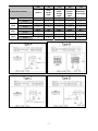
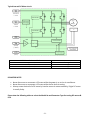
RAC Service Tool Kit Instruction Manual – Version 1.1 PURPOSE: This service tool kit has been developed to improve accuracy when testing and diagnosing components incorporated in Mitsubishi Heavy Industries “S” series Air‐Conditioners. Test and operate DC fan motors with manual variable speed control Test PCB voltage output to DC fan motors with manual variable speed control Test output from transistors to inverter compressor Monitor operational data and error codes Recover operational data log from SD memory card or PC Tools DMCT CCCT COMT INVERTER Part CHECKER ◙ DC Motor ◙ ◙ PWB 1 (Main) ◙ PWB 2 (Power) ◙ PWB 3 (Capacitor) ◙ Compressor ◙ Thermistor’s Service Tool DC Motor Checker (DMCT) Control Circuit Checker (CCCT) Inverter Checker (ICT) Communication Checker (COMT) Function o Operate the DC Motor external of PCB o Noise Test of DC motor at various rpms o Confirm PCB voltage output to DC Motor o Confirm response from DC Motor to PCB o Visually view output from PCB/ Transistor to compressor o View Error display o Check operation data (Temperatures, Current, Hz etc) ‐ 1 ‐ 1. Connect the wiring correctly as detailed in the instructions, incorrect termination or configuration could result in electric shock or fire. 2. be sure to fasten the wiring firmly, never connect data wiring (No 3) to high voltage 3. Confirm that voltage has been discharged before touching wiring (Less than 10VDC) as capacitors store voltage. 4. Only licensed and qualified staff should operate these service tools 5. be sure to turn off the power prior to installation Note Mitsubishi Heavy Industries do not accept any responsibilities for any technical trouble that may occur during the use of these tools Mitsubishi Heavy Industries reserves the right to change specifications without any advanced notice ‐ 2 ‐ SPECIFICATION: Power source: 1 phase 220/240V 50Hz Operation Temperature: 0 to 43°C Relative Humidity: Max 85% RH Weight: 6.5kg (Inc Tools) CONTENT: Part No: RMA006A001 Description: SERVICE TOOL ASSY Name: RAC Service Tool Kit 1.0.0 TOOL CASE 2.0.0 DMCT‐ CCCT CHECKER TOOL 2.1.1 TRANSFER BOX‐TYPE A (DMCT) 2.1.2 CABLE FOR DC MOTOR TYPE B (DMCT) 2.1.3 TRANSFER BOX‐TYPE C (DMCT) 2.1.4 TRANSFER BOX‐TYPE D (DMCT) 2.2.1 CABLE FOR TYPE A (CCCT) 2.2.2 CABLE FOR TYPE B (CCCT) 2.2.3 CABLE FOR TYPE C (CCCT) 2.2.4 CABLE FOR TYPE D (CCCT) 3.0.0 INVERTER CHECKER (ICT) 4.0.0 COMMUNICATION TOOL (COMT) 1. TOOL CASE (RMA006A000) ‐ 3 ‐ 2. DMCT‐ CCCT CHECKER TOOL (RMA006A002) FUNCTION & USAGE The checker tool is used to test DC fan motor operation (DMCT) & PCB output (CCCT) to DC fan motor. ‐ 4 ‐ CCCT The indoor unit PCB supplies voltage output to vary the speed of the DC motor, these outputs are displayed on the checker tool by rotating the variable switch When testing the voltage output from the PCB, there is no need to supply power to the checker tool, the air‐conditioner power supply is used to display reading from the checker tool. The LED display will confirm the various outputs to the DC fan motor and the response input from the DC fan motor. DMCT The checker tool with AC power applied can drive the DC fan motor directly without use of the PCB. The speed of the fan motor can be controlled by rotating the variable switch. The LED display will confirm the input and output signals of the DC motor to be correct. Note: The motor should be tested with a multi meter prior to connection to avoid blowing the fuse on the checker tool. TRANSFER BOX & CABLE FOR DMCT The transfer boxes (Lead only for type B) are used to connect the various types of DC fan motor plugs to the checker tool connector DMCT. You will need to check the compatibility table to determine the interface for each DC Motor, please do this carefully. CONNECTION CABLE FOR CCCT The CCCT connection cables are used to connect the various types of PCB connections to the checker tool connector CCCT and confirm the output from the PCB is OK. ‐ 5 ‐ Check Procedure for DC Motor check (DMCT) 1. Check the DC motor rotation by hand – OK? 2. Check the Model No and Part No in the following tables – Select the Type A, B, C or D 3. Check the resistance of the DC motor as per page 8 – OK? 4. If resistance is OK connect the DC motor using the correct type of transfer box or cable 5. Apply power to the checker tool – set the speed controller to the minimum setting 6. Check Voltage ‐ Vm to Gnd= 330VDC Vcc to Gnd= 15VDC approx. If no DC voltage is found, check if the fuses on the checker tool are OK? When the speed controller is turned clockwise, observe if Vsp (Orange LED) and Vfg (Blue LED) are flashing on and off? If so the motor will now turn if normal. 7. Observe that the DC motor operates correctly – OK? 8. If no operation turn off power and check fuse ‐ OK? 9. Conclude if DC motor is OK? 10. Disconnect the motor from the checker tool Check Procedure for PCB (CCCT) 1. Turn the power off to the air conditioner and checker ( Checker is power by PCB) 2. Check the appearance of the PCB – fuse, varistor and other components are not damaged – OK? 3. Select the PWB transfer cable from the model table – Type A, B, C or D 4. Connect the transfer cable between the PCB and checker tool, set the speed controller to minimum setting 5. Turn power on to the air conditioner and send a command from the remote controller to start the outdoor fan motor 6. Check Voltage ‐ Vm to Gnd= 330VDC. Vcc to Gnd= 15VDC approx. If no DC voltage is found, check if the fuses on the checker tool are OK? If PWB output is OK increase the speed controller, Vsp (Orange LED) & Vfg (Blue LED) will flash on and off, indicating PWB pulse input Vsp (Orange LED) to CCCT has been received and a signal has been sent back to PWB by CCCT pulse output ‐ Vfg (Blue LED). Note: Dependant on remote control settings Vsp (Orange LED) may light up solid or go out, as compressor may be at max Hz and PWB output Vsp (Orange LED) to CCCT is now at high speed. VFG (Blue LED) will only flash on & off at any stage of this test when the speed controller is turned in the clockwise direction. 7. Conclude if PCB is OK? ‐ 6 ‐ GND Vm Vsp Speed Control Voltage Input Yellow Revolution Pulse Output Red Vcc Control Power Voltage Input White Ground Motor Voltage Input Wire Colour Black PIN No 3 1 4 5 6 Wire Colour Blue Red Brown Orange White PIN No 4 6 3 2 1 Wire Colour PIN No Black 4 Red 1 White 6 Yellow 5 Blue 3 Wire Colour Black Red White Yellow Blue PIN No 4 6 3 2 1 DC fan motor connector TYPE A TYPE B TYPE C TYPE D V FG Blue ‐ 7 ‐ Typical Internal DC Motor circuit Multi Meter Resistance Check GND (Black Probe) 200 kΩ or higher 25 kΩ or higher 1 MΩ or higher Vsp (Red Probe) Vcc (Red Probe) Vm (Red Probe) DC MOTOR NOTES Never disconnect or reconnect a DC motor while the power is on to the air conditioner. Never disconnect or reconnect a DC motor while the fan shaft is turning. Always rotate the shaft of a DC motor by hand to ensure is rotates smoothly, if tight DC motor is usually faulty. Please view the following tables to select the Model No and Connector Type for testing DC motors & PCB. ‐ 8 ‐ Indoor DC fan motor (CNU) Model SRK20ZG‐S SRK20ZJ‐S SRK20ZIX‐S SRK20ZJX‐S SRK25ZD‐S SRK25ZGA‐S SRK25ZJ‐S SRK25ZDXA‐S SRK25ZGX‐S SRK25ZIX‐S SRK25ZJX‐S SRK35ZDA‐S SRK35ZGA‐S SRK35ZJ‐S SRK35ZDXA‐S SRK35ZGX‐S SRK35ZIX‐S SRK35ZJX‐S SRK56HEA‐S SRK50ZDA‐S SRK50ZJ‐S SRK50ZFX‐S SRK50ZGX‐S SRK50ZHX‐S SRK50ZIX‐S SRK50ZJX‐S SRK60ZHX‐S SRK60ZIX‐S SRK60ZJX‐S SRK63ZEA‐S SRK63ZEA‐S1 SRK71ZEA‐S SRK71ZEA‐S1 SRK80ZEA‐S SRK80ZEA‐S1 SRK80ZEA‐S2 SRF50ZIX‐S SRF35ZIX‐S SRF25ZIX‐S SRF50ZJX‐S SRF35ZJX‐S SRF25ZJX‐S SKM20ZG‐S SKM22ZG‐S SKM25ZG‐S SKM28ZG‐S SKM35ZG‐S SKM50ZF‐S SKM50ZG‐S SKM60ZG‐S SKM71ZG‐S Part No. SSA512T081 SSA512T081B SSA512T092 SSA512T092 SSA512T064B SSA512T081 SSA512T081B SSA512T046F SSA512T046F SSA512T092 SSA512T092 SSA512T064B SSA512T081 SSA512T081B SSA512T046F SSA512T046F SSA512T092 SSA512T092 SSA512T046F SSA512T064B SSA512T081B SSA512T046F SSA512T046F SSA512T092 SSA512T092 SSA512T092 SSA512T093 SSA512T092 SSA512T092 SSA512T072A SSA512T072A SSA512T072A SSA512T072A SSA512T072A SSA512T072A SSA512T072A SSA512T072B SSA512T072B SSA512T072B SSA512T072C SSA512T072C SSA512T072C SSA512T081 SSA512T081 SSA512T081 SSA512T081 SSA512T081 SSA512T064B SSA512T081 SSA512T072A SSA512T072A Type of connector A A A A A A A A A A A A A A A A A A A A A A A A A A A A A A A A A A A A A A A A A A A A A A A A A A A RPM (@ Vsp 6.5V) 2479 2479 2307 2307 2079 2479 2479 2340 2340 2307 2307 2079 2479 2479 2340 2340 2307 2307 2340 2079 2479 2340 2340 2307 2307 2307 2010 2307 2307 1780 1780 1780 1780 1780 1780 1780 1780 1780 1780 1780 1781 1782 2479 2479 2479 2479 2479 2079 2479 1780 1780 ‐ 9 ‐ Vm Vcc Vsp V FG 200 ~ 375 200 ~ 375 200 ~ 410 200 ~ 410 240 ~ 375 200 ~ 375 200 ~ 375 50~370 50~370 200 ~ 410 200 ~ 410 240 ~ 375 200 ~ 375 200 ~ 375 50~370 50~370 200 ~ 410 200 ~ 410 50~370 240 ~ 375 200 ~ 375 50~370 50~370 200 ~ 410 200 ~ 410 200 ~ 410 90 ~ 185 200 ~ 410 200 ~ 410 50 ~ 370 50 ~ 370 50 ~ 370 50 ~ 370 50 ~ 370 50 ~ 370 50 ~ 370 50 ~ 370 50 ~ 370 50 ~ 370 50 ~ 370 51 ~ 370 52 ~ 370 200 ~ 375 200 ~ 375 200 ~ 375 200 ~ 375 200 ~ 375 240 ~ 375 200 ~ 375 50 ~ 370 50 ~ 370 13.5~16.5 13.5~16.5 13.5~16.5 13.5~16.5 13.5~16.5 13.5~16.5 13.5~16.5 13.5~16.5 13.5~16.5 13.5~16.5 13.5~16.5 13.5~16.5 13.5~16.5 13.5~16.5 13.5~16.5 13.5~16.5 13.5~16.5 13.5~16.5 13.5~16.5 13.5~16.5 13.5~16.5 13.5~16.5 13.5~16.5 13.5~16.5 13.5~16.5 13.5~16.5 13.5~16.5 13.5~16.5 13.5~16.5 13.5~16.5 13.5~16.5 13.5~16.5 13.5~16.5 13.5~16.5 13.5~16.5 13.5~16.5 13.5~16.5 13.5~16.5 13.5~16.5 13.5~16.5 13.5~16.6 13.5~16.7 13.5~16.5 13.5~16.5 13.5~16.5 13.5~16.5 13.5~16.5 13.5~16.5 13.5~16.5 13.5~16.5 13.5~16.5 0 ~ 7.3 0 ~ 7.3 0 ~ 7.3 0 ~ 7.3 0 ~ 7.3 0 ~ 7.3 0 ~ 7.3 0~6.5 0~6.5 0 ~ 7.3 0 ~ 7.3 0 ~ 7.3 0 ~ 7.3 0 ~ 7.3 0~6.5 0~6.5 0 ~ 7.3 0 ~ 7.3 0~6.5 0 ~ 7.3 0 ~ 7.3 0~6.5 0~6.5 0 ~ 7.3 0 ~ 7.3 0 ~ 7.3 0 ~ 6.5 0 ~ 7.3 0 ~ 7.3 0 ~ 6.5 0 ~ 6.5 0 ~ 6.5 0 ~ 6.5 0 ~ 6.5 0 ~ 6.5 0 ~ 6.5 0 ~ 6.5 0 ~ 6.5 0 ~ 6.5 0 ~ 6.5 1 ~ 6.5 2 ~ 6.5 0 ~ 7.3 0 ~ 7.3 0 ~ 7.3 0 ~ 7.3 0 ~ 7.3 0 ~ 7.3 0 ~ 7.3 0 ~ 6.5 0 ~ 6.5 12 12 12 12 12 12 12 12 12 12 12 12 12 12 12 12 12 12 12 12 12 12 12 12 12 12 12 12 12 12 12 12 12 12 12 12 12 12 12 12 13 14 12 12 12 12 12 12 12 12 12 Outdoor DC fan motor (CNA) Model SRC20ZG‐S SRC20ZJ‐S SRC20ZIX‐S SRC20ZJX‐S SRC25ZDA‐S SRC25ZG‐S SRC25ZJ‐S SRC25ZDXA‐S SRC25ZGX‐S SRC25ZIX‐S SRC25ZJX‐S SRC35ZDA‐S SRC35ZG‐S SRC35ZJ‐S SRC35ZDXA‐S SRC35ZGX‐S SRC35ZIX‐S SRC35ZJX‐S SRC40ZHX‐S SRC40ZIX‐S SRC50ZFX‐S SRC50ZGX‐S SRC50ZHX‐S SRC50ZIX‐S SRC60ZHX‐S SRC60ZIX‐S SRC63ZE‐S SRC63ZE‐S1 SRC71ZE‐S SRC71ZE‐S1 SRC80ZE‐S SRC80ZE‐S1 SRC80ZE‐S2 SCM40ZF‐S SCM40ZG‐S SCM40ZJ‐S SCM45ZF‐S SCM45ZG‐S SCM48ZF‐S SCM48ZG‐S SCM50ZJ‐S SCM60ZF‐S SCM60ZG‐S SCM60ZJ‐S SCM80ZF‐S SCM80ZG‐S SCM80ZJ‐S Part No. SSA512T075 SSA512T094 SSA512T094 SSA512T094 SSA512T038D SSA512T075 SSA512T094 SSA512T038D SSA512T075 SSA512T094 SSA512T094 SSA512T038D SSA512T075 SSA512T094 SSA512T038D SSA512T076 SSA512T094 SSA512T094 SSA512T091A SSA512T091A SSA512T061B SSA512T061B SSA512T091A SSA512T091A SSA512T091A SSA512T091A SSA512T076C SSA512T076C SSA512T076C SSA512T076C SSA512T076C SSA512T076C SSA512T076C SSA512T061B SSA512T061B SSA512T061B SSA512T061A SSA512T061B SSA512T061A SSA512T061B SSA512T061B SSA512T061A SSA512T061B SSA512T061B SSA512T076C SSA512T076C SSA512T076D Type of connector D D D D D D D D D D D D D D D B D D D D B B D D D D B B B B B B B B B B B B B B B B B B B B B RPM (@ Vsp 6.5V) 1867~2284 1690 1690 1690 1917~2343 1867~2284 1690 1917~2343 1867~2284 1690 1690 1917~2344 1867~2284 1690 1917~2343 1900 1690 1690 1342~1641 1342~1641 1850 1850 1342~1641 1342~1641 1342~1641 1342~1641 1950 1950 1950 1950 1950 1950 1950 1850 1850 1850 1690 1850 1690 1850 1850 1690 1850 1850 1950 1950 1900 ‐ 10 ‐ Vm Vcc Vsp V FG 120 ~ 375 50 ~ 370 50 ~ 370 50 ~ 370 120~375 120 ~ 375 50 ~ 370 120~375 120 ~ 375 50 ~ 370 50 ~ 370 120~375 120 ~ 375 50 ~ 370 120~375 50 ~ 400 50 ~ 370 50 ~ 370 70 ~ 410 70 ~ 410 200 ~ 410 200 ~ 410 70 ~ 410 70 ~ 410 70 ~ 410 70 ~ 410 50 ~ 450 50 ~ 450 50 ~ 450 50 ~ 450 50 ~ 450 50 ~ 450 50 ~ 450 200 ~ 410 200 ~ 410 200 ~ 410 200 ~ 410 200 ~ 410 200 ~ 410 200 ~ 410 200 ~ 410 200 ~ 410 200 ~ 410 200 ~ 410 50 ~ 450 50 ~ 450 50 ~ 450 14 ~ 16 13.5 ~ 16.5 13.5 ~ 16.5 13.5 ~ 16.5 14~16 14 ~ 16 13.5 ~ 16.5 14 ~ 16 14 ~ 16 13.5 ~ 16.5 13.5 ~ 16.5 14~16 14 ~ 16 13.5 ~ 16.5 14~16 13.5~16.5 13.5~16.5 13.5 ~ 16.5 14 ~ 16 14 ~ 16 13.5~16.5 13.5~16.5 14 ~ 16 14 ~ 16 14 ~ 16 14 ~ 16 13.5~16.5 13.5~16.5 13.5~16.5 13.5~16.5 13.5~16.5 13.5~16.5 13.5~16.5 13.5~16.5 13.5~16.5 13.5~16.5 13.5~16.5 13.5~16.5 13.5~16.5 13.5~16.5 13.5~16.5 13.5~16.5 13.5~16.5 13.5~16.5 13.5~16.5 13.5~16.5 13.5~16.5 0 ~ 7.3 0 ~ 6.5 0 ~ 6.5 0 ~ 6.5 0~7.3 0 ~ 7.3 0 ~ 6.5 0~7.3 0 ~ 7.3 0 ~ 6.5 0 ~ 6.5 0~7.3 0 ~ 7.3 0 ~ 6.5 0 ~ 7.3 0 ~ 6.5 0 ~ 6.5 0 ~ 6.5 0 ~ 7.3 0 ~ 7.3 0 ~ 6.5 0 ~ 6.5 0 ~ 7.3 0 ~ 7.3 0 ~ 7.3 0 ~ 7.3 0~6.5 0~6.5 0~6.5 0~6.5 0~6.5 0~6.5 0~6.5 0 ~ 6.5 0 ~ 6.5 0 ~ 6.5 0 ~ 6.5 0 ~ 6.5 0 ~ 6.5 0 ~ 6.5 0 ~ 6.5 0 ~ 6.5 0 ~ 6.5 0 ~ 6.5 0~6.5 0~6.5 0~6.5 12 12 12 12 12 12 12 12 12 12 12 12 12 12 12 12 12 12 12 12 12 12 12 12 12 12 12 12 12 12 12 12 12 12 12 12 12 12 12 12 12 12 12 12 12 12 12 3. INVERTER CHECKER TOOL (RMA006A003) FUNCTION & USAGE The inverter checker tool is used to verify the correct voltage is supplied to the compressor ‐ 11 ‐ Connection procedure of the inverter checker 1. Turn the power supply off. (Breaker or Isolator OFF) 2. Disconnect the wiring of compressor from the PCB 3. Connect the wiring of the inverter checker (U = red, V = white, W = blue) to the terminals of the PCB 4. Turn the power supply on. 5. Set the unit to cooling 18oC to initiate a compressor on command 6. All LED’s (1~6) should flash to confirm correct output from PCB to compressor 7. Depending on the control logic after a period of time the unit will activate and stop on under‐current ‐ 12 ‐ 4. COMT – RMA006A014 COMMUNICATION TOOL 2 3 4 5 Serial Data Connector USB Connector to PC SD Card RAM Data connector FUNCTION & USAGE The communication tool is used to view operational and communication data from the system The data saved to the SD card and software will soon be developed to read these files in csv and graphical format on a PC Connection procedure of the inverter checker (1) Select connector type of COMT from A/C model. (2) Turn off unit and breaker before connecting COMT every time. (3) Connect cable of COMT to A/C unit. ‐ Serial connection; just only uses Serial connection cable. ‐ RAM connection; have to open Panel front assy of outdoor unit when connect RAM Please connect both of RAM and serial connection cable. (4) Turn on breaker and A/C unit. (5) See display of COMT. ‐ 13 ‐ (6) Main menu page. ‐ Input file name to record. ‐ Select sampling time; 10 or 60 sec. ‐ Select type of connector; Serial, Multi, RAM, EEPROM (7) When select go to log mode and type connector of ROM finish. Display will show communication data between indoor and outdoor unit. Please see running communication data to check. (8) Service man has to analysis data and compare with normal condition. (9) If outdoor unit has problem or error. Display of COMT will show alarm and explain on the last page. ‐ 14 ‐ Fig. 1 Outline of COMT and SD card 1. Connection cable of COMT (connect to outdoor unit) 1.1 Serial 1.2 RAM Fig 2 Connection cables of COMT 1.1 Serial for SRK**ZG, SRK**ZE model. (Connect Serial only) 1.2 RAM for SRK**ZHX, SRK**ZIX, SRK**ZJ, SRK**ZJX models (Connect Serial & RAM) ‐ 15 ‐ ‐ 16 ‐