1
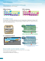
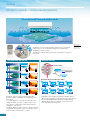
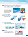
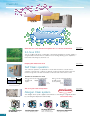
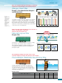
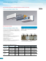
High Performance Air Conditioning
SR
series
Residen t i a l A i r C o n d i t i o n e r s
Wall Mounted type
SRK
COP 5.71
( in theSRK20ZIX-S
cooling operation )
3D AUTO
Programmed air distribution
Sophisticated design
Quiet operation
Industry leading energy effi
from our advanced technol
ZIX series
ficiency and reliability
logy.
Floor Standing type
SRF
COP 4.80
( in theSRF25ZIX-S
cooling operation )
Auto air outlet selection
lower and upper outlets
Sophisticated design
Quiet operation
High Efficiency
The industry’s highest EER COP levels
The ZIX, ZG and ZE series clear the 2010 MEPS.
EER in Cooling
COP in Heating
5.71
5.20
5.5
5.0
4.5
4.14
4.0
5.5
3.33
5.26
5.0
3.42
3.23
3.33
4.48
4.5
2.93
3.85
3.5
5.56
4.44
4.07
4.0
3.82
3.62
2.93
3.5
3.21
3.0
3.0
2.5
2.5
SRK20ZIX-S SRK25ZIX-S SRK35ZIX-S SRK50ZIX-S SRK60ZIX-S SRK63ZE-S1 SRK71ZE-S1
SRK20ZIX-S SRK25ZIX-S SRK35ZIX-S SRK50ZIX-S SRK60ZIX-S SRK63ZE-S1 SRK71ZE-S1
DC PAM inverter
An inverter system has a number of advantages over a constant speed system. Its variable speed compressor outputs
can ensure quick cooling or heating after start up and attains a set temperature more quickly. The air conditioner can
slow down the compressor speed to save energy whilst keeping comfortable conditions. The compressor is DC motor
driven so it provides higher performance.
Time
DC PAM
INVERTER
DC
PowerActiveModule
PAM
INVERTER
Room Temp.
PAM
PWM
Set Temp.
Even Temperature
DC PAM
INVERTER
Rated Capacity
ON
Compressor
(rps)
Utmost comfort and energy efficiency achieved
with large output power and control optimisation
DC compressor motor
Time
CONVENTIONAL
INVERTER
Motor Efficiency(%)
Magnet Motor
Room Temp.
Improving
Set Temp.
Improving
CONVENTIONAL
Induction Motor
Low
Revolution speed
High
ON
Rated Capacity
OFF
Compressor
(rps)
Less advanced technology does not address
the ON/OFF cycle issue.
New Inverter Control (Vector control)
New Inverter Control has applied the new advanced technology of Vector control enabling:• Smooth operation from low to high speed
• Smooth Sine Voltage Wave form is achieved
• Energy efficiency has improved in low speed range
4
OFF
High Efficiency
Our Latest Technologies
New propeller fan
Silicon-coated PCB
The new propeller fan was
carefully matched with a fan
motor in order to keep the same
capacity as that of previous
models with less electrical
consumption. In synergy with
the leaf shape grill has seen an
improvement of energy efficiency
by 5% and a decrease of sound
level.(SRC50/60ZIX-S)
The printed circuit board of the outdoor unit is
coated by silicon. The coating ensures longevity
of the board in humid conditions.
Energy saving leaf shape grill
The leaf shape grill was developed in order to
maximize natural air flow sent by the propeller
fan along the grill. The airflow is very smooth with
minimum air resistance. This has lead to a decreased
fan motor load and improvement of energy efficiency.
High efficiency scroll
compressor. Low vibration
and low sound revel
By using a scroll compressor there
has been an improvement of energy
efficiency. Lower vibration and lower
sound level have been achieved.
Further improvement to efficiency was
realized by use of a neodymium magnet
applied in the compressor motor.
(SRC50/60ZIX-S)
ZAM steel sheet
ZAM steel sheet is used on the base of the
outdoor units. ZAM has superior corrosion
resistance and scratch resistance properties
compared to conventional materials.
1) ZAM is a registered trademark of Nissin
Steel Co., Ltd.
2) ZAM is a coined name applied to hotdipped zinc-aluminum-magnesium-alloycoated steel sheet developed by Nissin Steel
Co., Ltd.
photo is composite image
Indoor unit
Outdoor unit
A combination of fin configuration and
copper tube has enabled maximum air
flow whille keeping the same size width
of the indoor unit.
Efficiency rate of heat exchanger has
been drastically improved by 30%
compared with previous models. The
new fin design allows maximum air flow
and saving energy simultaneously.
Redesigned by changing the fin
configuration from flat sheet to new
M shape fin, efficiency has been
improved by 10%. An optimum
balance of heat transfer and air flow
has been achieved.
R e s i d e n t i a l A i r C o nditioners
5
Airflow
3D AUTO Vertical + Horizontal AIR SCROLL
3 motors make 3 independent controls
Programmed air distribution
Applied models
3D AUTO
3D AUTO is a one touch programme. Three motors (one vertical
working motor + two horizontal working motors) make three
independent air flow controls.
The airflow is uniform, quiet and reaches at long distance from the
indoor unit.
Programmed 3D AUTO
Hi-Power (Quick)
Cool Shower
1
SRK-ZIX, SRK-ZG,
SKM-ZG
SRK63/71/80ZE,
Manual Setting only
Manual Setting
Floor Heating
Vertical Swing
Swing
Wide Swing (Every Corner)
Swing
2
Horizontal Air Scroll 8 Direction Swing
Center (Long)
3
Swing
3
4
8
7
6
5
Cool Shower
Floor
Automatic control of air flow volume and air flow
direction enables comfortable air conditioning of the
entire room.
In cooling operation, cooled air flows directly to the
ceiling not directly onto the occupants of the room.
The comfort cooled air flow comes down from the
ceiling like a soft shower.
In heating operation, warm air flows to the floor directly
and spreads along the floor. The concentration of the
warm air at floor level increases comfort.
6
2
Swing
Wide-Air (Equal)
4
1
Swing
Spot
Wide
Individual control of right and left louver enables air flow
direction from the right and the left side of the unit, setting
the most preferable air flow direction and determining
whether direct air flow is required or not. At the same
time, this minimises energy loss.
Airflow
Applied models
All SRK, SKM
Aircraft technology was used in the design of the air conditioner’s airflow system
Jet Air Scroll Long Reach & Silent Air Flow
We used the same aerodynamic analysis technology as
used in developing jet engines.
CFD (computational fluid dynamics) is used
for blade shape design and air channels for
jet engines. The same technology has been
used in our air conditioners. The airflow
of the jets created in this system enables
a large volume of air to be blown with a
minimum amount of power consumption.
The airflow is uniform, quiet and reaches a
long distance from the indoor unit.
Fast
Slow
Colors in the figure show the air speed.
Applied models
SRK50/60ZIX,
SRK63/71/80ZE
Long Reach Air Flow
The jet technology enables powerful
airflow ideal for large living areas and
commercial premises, increasing
your comfort.
SRK50/60ZIX
15m
Applied models
SRK-ZIX, SRK-ZG,
SKM-ZG
Applied models
SRK-ZIX
SRK63/71/80ZE
(in cooling operation)
(in cooling operation)
17m
powerful
Positioning of Installation
You can set the left-right air flow directions when you
install the air conditioner near the side wall by remote
controller operation.
New louver
The new louver has a new design and shape.It has
increased in surface area by 80%. In addition to
improved control of the increased air flow volume, it
has improved controllability of the right to left swing
function.
80% increased
previous
New
R e s i d e n t i a l A i r C o nditioners
7
Clean Air
Generates the same amount of negative ions as a forest environment
Applied models
All SRK, SKM
24-hour ION
The air conditioner body has a tourmaline coated sheet. Negative ions (2,500 -3,000/cc)
are generated even when the air conditioner is not running, allowing you to experience
them without incurring any electrical cost.
Keeping the indoor unit clean
Applied models
All SRK, SKM
Self Clean operation
The ‘self clean operation’ is operated for 2 hours after the unit has ceased normal
operation. The indoor fan continues to operate on ultra low speed to dry the unit. This
restricts the growth of mould. This feature can be selected on the remote control.
Stop run
Normal
operation
Situation of mold after one week
2hrs
Clean
operation
When you don’t execute “Self Clean Operation”
Fungal mycelia
expand.
Fungal
mycelia
When you execute “Self Clean Operation”
The spore of mold
doesn't germinate.
Spore
of mold
Shuts off automatically
The air in your room is kept fresh
Allergen Clear system
Push ALLERGEN Mode
Catching Allergen
on the Filter
8
Spore
of mold
First in the world
The ‘Allergen Clear system’ suppresses the influence of the allergen caught by the filter
by controlling the temperature and humidity.
20 of Patent Pending
Cooling Operation
To make condensing water.
Heating Operation
To give moisture to the
Filter to inactivate allergen
AIR Purify
Self-Clean Operation
To dry up the indoor unit
Applied models
SRK-ZIX, SRK-ZG,
SRK-ZE
Clean Air
This is the original and only technology to control the
temperature and humidity for inactivating allergens
Allergen Clear Filter
Sterilization Mechanism
Enzyme + Urea deactivates allergens
and kills bacteria
Urea
H2N-
Enzyme
Slack of high order structure
Reduction in a molecule
-COOH
Protein structure of allergen
A molecule is decomposed
Rate of inactivation against allergens collected on the filter
93.6%
100
The allergen clear filter deactivates pollen lice and allergens
that live on cat skin etc. The deactivation secret is the
Enzyme-urea compound. It deactivates not only allergens
but some bacteria, moulds and viruses. Even if allergen,
mould, virus or bacteria fly off the filter they are deactivated
so the air in your room is kept fresh.
Inactivation rate(%)
Virus i
Virus p
50
0
House dust mite A species of mite
*1
*1
Cedar pollen
*2
Epithelium of cat
*2
*3
*3
First in
the world
Natural Enzyme Filter
Conventional Filter
Analysis Zone
The enzymes used in these filters are naturally occurring
lytic enzymes. Lytic enzymes attack cell walls of
microorganisms trapped on the filter and destroy them.
The Natural Enzyme Filter will clean and sanitize air
passing through it.
99.0%
72.7%
Helps to destroy fungi and bacteria, also effective on
viruses and allergenic compounds
(Cat hair, dust mite, pollen etc.)
Enzyme filter
99.9%
83.5%
83.5%
Enzyme Filter
Airflow
*1 Test method:
ELISA colorimetric method /
ELISA fluorescent method
Laboratory:
Independent administrative
agency national hospital
mechanism Sagamihara
Hospital, No.1536
*2 Test method:
ELISA colorimetric method
Laboratory:
Independent administrative
agency national hospital
mechanism Sagamihara
Hospital, No.1536
*3 Test method:
TCID (Infection value 50%)
Laboratory:
Foundation of Kitazato
Environmental Science Center,
No.15-0145
Analysis Zone
Enzyme's sterilizing mechanism
Bacterium
Enzyme
Enzyme
Coupling
Powerful
sterilizing effect
Cell wall
Filter fiber
The deodorizing ability of this filter can be easily
restored simply by cleaning and exposing to the sunlight
Photocatalytic Washable Deodorizing Filter
This filter will keep the air fresh by deodorizing the
molecules that cause odours. The deodorizing effect
can be restored by washing with water and then drying
under the sun. This filter maintains its deodorizing effect
even after many repeat uses.
Used in models
Indoor Unit
SRK-ZIX
SRK-ZE
SRK-ZG
SRF-ZIX
Allergen Clear Filter
1pc
1pc
1pc
-
-
Natural Enzyme Filter
-
-
-
1pc
1pc
Photocatalytic Washable Deodorizing Filter
1pc
1pc
1pc
1pc
1pc
Filter
SKM-ZG
R e s i d e n t i a l A i r C o nditioners
9
Advanced Technology
Anti-microbial specifications and design will deliver cleanliness and safety
Applied models
Anti-microbial indoor fan
All SRK, SKM
Anti-microbial treatment
Anti-microbial indoor fan
The indoor fan has undergone anti-microbial treatment
to resist growth of mould and germs. Mould creating
odours which can occur when an air conditioner is not in
operation are prevented.
·Intestinal bacteria (Escherichia coli IFO 3972)
·Staphylococcus aureus subsp. aureus IFO 12732
Testing Authority: Japan Food Analysis Center
Test Results Issued: 2004-4-7.
Test Report No.: 104034022-001
Tests were conducted with reference to the antimicrobial strength tests in
JIS Z 2801 2000 “Antimicrobial Products-Antimicrobial Test Method” –5.2
Antimicrobial Effects: Test Methods for Plastic Products, etc.
·Apergillus niger IFO 6341
Testing Authority: Japan Food Analysis Center
Test Results Issued: 2004-4-23.
Test Report No.: 104034022-002
Tests were conducted with reference to the antimicrobial strength tests in
JIS Z 2801 2000 “Antimicrobial Products-Antimicrobial Test Method” –5.2
Antimicrobial Effects: Test Methods for Plastic Products, etc.
Comparison of growth of bacteria and mold on fan surfaces
(microscopic image)
without
with
Anti-microbial Anti-microbial
without
with
Anti-microbial Anti-microbial
Aspergillus niger IFO 6341
Escherichia coli IFO 3972
In tests conducted at the Mitsubishi Heavy Industries Nagoya Research Lab,
24 hrs after contact with bacteria, cultured on agar media.
Live Bacteria Count on Measured Test Pieces
Tested
Contaminant
Escherichia coli
IFO 3972 coli
Staphylococcus
aureus
Aspergillus
niger
Test Pieces
Immediately after contact
Not treated
Measurement 1
1.9 x 10⁵
After 24 hrs
at 35°C
Test piece 1
Not treated
<10
3.8 x 10⁶
<10
4.9 x 10⁶
<10
7.2 x 10⁶
Immediately after contact
Not treated
1.4 x 10⁵
1.6 x 10⁵
1.3 x 10⁵
After 24 hrs
at 35°C
Test piece 1
Not treated
<10
8.6 x 10⁵
<10
4.5 x 10⁵
<10
3.6 x 10⁵
Immediately after contact
Not treated
1.5 x 10⁴
2.2 x 10⁴
1.6 x 10⁴
After 24 hrs
at 35°C
Test piece 1
Not treated
<10
1.0 x 10⁴
<10
1.2 x 10⁴
<10
2.5 x 10⁴
Test Pieces 1) Products with Antimicrobial and Antifungal Treatment
10
Bacteria Count Per Test Piece
Measurement 2
Measurement 3
1.6 x 10⁵
1.3 x 10⁵
Measurement
Advanced Technology
Applied models
SRK-ZIX, SRK-ZE,
SRK-ZG, SCM-ZG
SRF-ZIX
Wide Operation Range
Heating and cooling operations are possible at an outdoor
temperature as low as –15°C
-15°C
Our new advanced technology has improved the
heating and cooling operation range.
Units can be installed when heating or cooling operation
is required at low ambient conditions down to -15°C.
+21°C
Heating
-15°C
40
30
20
10
0
-10
-20
+46°C
Cooling
50
For the capacities under low temperature conditions,
refer to technical manual.
Silent airflow and long reach
Quiet operation
This is the secret of quiet operation
The combination of the jet airflow system and serration
stabilizer configuration ensures uniform breeze to every
corner of the room. It also makes it possible to lower the
operation noise further by minimizing the interaction
between airflow and the fan.
Applied models
SRK50/60ZIX,
SRF-ZIX
r everyday
ises in ou
miliar no
with fa
omparison
C
Nor
60dB
21dB
ns
ersatio
mal conv
70dB
life
e
Quiet offic
50dB
a
rary Late night in
ea
burban ar
typical su
In the lib
40dB
30dB
20dB
60dB
50dB
40dB
30dB
21dB
10dB
SRK20ZIX-S
0dB
(In the Cooling Lo mode)
Three sensors
Control of room temperature and humidity is very
important for people to live a comfortable life. Use of
three sensors to control indoor temperature, indoor
humidity and outdoor temperature enable the unit to
obtain optimum air-conditioning.
Sensor for indoor temperature
Sensor for outdoor temperature
Sensor for indoor humidity
Applied models
All SRK, SKM,
SRF
Applied models
SRK50/60ZIX,
SRK-ZE
SRF-50ZIX
Washable filter and easy cleaning of air inlet panel
Removing the air filter is quite easy. Keeping the air filter
clean is an effective way to save energy and
keep the original powerful performance of your unit.
The air inlet panel is also removable and
can be cleaned easily.
Long piping length
Piping length has been extended and design
flexibility has been improved.
Maximum pipe length
30m
Maximum height difference
20m
R e s i d e n t i a l A i r C o nditioners
11
Product line up
R410A
Model
SRK-ZIX series
SRF-ZIX series
Floor
Standing
type
2.5
20ZIX-S
25ZIX-S
35ZIX-S
50ZIX-S
25ZIX-S
35ZIX-S
50ZIX-S
2.8
6.3
7.1
7.5
8.0
63ZE-S1
71ZE-S1
80ZE-S2
80ZE-S1
NEW
60ZIX-S
NEW
HEAT
PUMP
DC
INVERTER
Capacity Range (kW : Rated cooling capacity)
3.5
4.0
5.0
6.0
2.0
SRK-ZE series
SRK-ZG series
20ZG-S
Model
SKM
25ZG-S
35ZG-S
2.0
2.2
2.5
2.8
3.5
20ZG-S
22ZG-S
25ZG-S
28ZG-S
35ZG-S
4.0
4.5
4.8
5.0
5.6
6.0
6.3
7.1
8.0
50ZG-S
Wall
mounted
type
60ZG-S
71ZG-S
SRRM
Ceiling
Concealed
type
INVERTER
Free-Multi
25ZF-S
35ZF-S
50ZF-S
60ZF-S
25ZF-S
35ZF-S
50ZF-S
60ZF-S
STM
4way ceiling
cassette type
600 x 600
Super Compact type
2 rooms
OUTDOOR UNIT
SCM
40ZG-S
45ZG-S
3 rooms
3 rooms
48ZG-S
60ZG-S
4 rooms
80ZG-S
12
Functions
Filter
Allergen
Filter
SUN
Filter
Allergen Clear Filter
The filter breaks down the pollen, lice, and all allergens that
live on cat skins, etc. and deactivates them.
Enzyme
Filter
Photocatalytic Washable Deodorizing Filter
Natural Enzyme Filter
Enzymes used in the filter are naturally occurring lytic
enzymes which attack cell walls of microorganisms trapped
on the filter and destroy them.
It keeps air fresh by deodorizing the molecules causing odor.
The deodorizing ability can be easily restored simply by
cleaning and exposing to the sunlight.
Comfortable Functions
Fuzzy Auto Mode
"HI POWER" Operation
Automatically the unit determines its operating mode and temperature
and setting based on a fuzzy calculation and adjusts the inverter
frequency.
The unit can operate continuously in HI POWER mode for 15 minutes.
This mode is used to reach the desired temperature quickly.
Sta
The air conditioner automatically selects from heating,
cooling or dry operation.
r t Sp
t
ur
Automatic Operation
3HOT
K
eep
Three "Hot" System
‘Hot start’ enables the unit to begin operation immediately.
‘Hot spurt’ a fast heating system that works to increase the
temperature setting by two degrees.
‘Hot keep’ used during the automatic defrost cycle to prevent cool air
being circulated.
These three operational control systems help ensure comfortable and
efficient heating.
Comfortable Air Flow Functions
3D Auto
Auto
You can choose the best heating or cooling pattern with the
touch of a button.
Auto Flap Auto Flap Mode
COOLING & DRY
Horizontal blowing
The unit automatically
selects the optimal
angle whatever the
operation mode.
Air Scroll Air Scroll
The swing of the
flap causes the air
flow to spiral and
the breeze reach all
corners of the
room.
HEATING
Slant forward
blowing
COOLING & DRY
Thick line
: moves quickly
Thin line
: moves slowly
HEATING
Thick line
Thin line
Memory Memory Flap
While the flap is swinging it can be stopped at any angle.
The flap returns to this position next time the unit starts
operation.
UP/DOWN Up/Down Flap Swing
SWING FLAP
The Up/Down flap can be adjusted to Flap moves up and down
continuously.
the preferred angle anywhere between
horizontal and perpendicular.
Lateral
Swing
Lateral swing
The louver swings from right to left automatically. Louver angle can
be fixed in any desired position.
Air outlet Air outlet selection
selection Both lower and upper air outlets and upper air outlet can be
selected.
Positioning of Installation
: moves quickly
: moves slowly
Positioning
You can set the left-right air flow directions when you
of
installation installed the air conditioner near the side wall by remote
controller operation.
Convenience & Economy Functions
24-hour On/Off Programmable Timer
On Timer On Timer
This enables the operation to start a little earlier so that the room is
near to set temperature at ON time.
Economy Economy Mode
The unit achieves effective energy saving operation while still keeping
a comfortable cooling or heating operation.
Dry Operation
DRY
The unit dehumidifies the room by intermittent cooling operation.
24h Timer By combining a start timer with a stop timer you can register two
timer operations a day. Once set timers will start or stop the system
at the specified time of the day repeatedly.
OFF Timer Off Timer
The unit stops at the specified time.
Sleep
Sleep Mode
The room temperature is automatically controlled during that set
sleep mode period ensuring that the room temperature will not get
too hot or cold.
Maintenance & Prevention Functions
MC
Microcomputer-Operated Defrosting
This function automatically eliminates frost and helps
minimize excessive operation in other modes.
Detachable Detachable Indoor Air Inlet Panel
The air inlet panel on the indoor unit opens and closes easily
making filter cleaning simple. The suction panel can be
easily removed.
Self-Diagnostic Function
Self
Diagnostic If the air conditioner malfunctions an internal microcomputer
When removing the air inlet panel
for internal cleaning or other reason,
open the grill by 65 degrees and
then pull it to the side.
runs a self diagnosis. Inspection and repair should be
performed by authorized dealers.
Others
Back-up Back-up Switch
Switch On the indoor unit there is a back up on/off switch. The system will
operate in the previous mode.
Auto Auto Restart Function
Restart Power blackout auto restart function records the operational status
of the air conditioner immediately prior to being switched off by
power supply interruption. The unit automatically resumes operations
in that mode and temperature set point after the power has been
restored.
24-hour ION
24h ION
Luminous
The air conditioner body has a tourmaline coated sheet. Negative
ions (2,500 -3,000/cc) are generated when the air conditioner is
not running, allowing you to experience them without incurring any
electrical cost.
Luminous Button
With wireless “Luminous” remote controls that even “glow in the
dark”, it is possible to operate all desired functions of the unit with
the click of a button.
R e s i d e n t i a l A i r C o nditioners
13
INVERTER
HEATPump
PUMPModel
MODEL(High
(HighCOP)
COP)
Inverter Heat
SRK-ZIX series
NEW
R410A
SRK20ZIX-S, SRK25ZIX-S, SRK35ZIX-S
SRK50ZIX-S, SRK60ZIX-S
SRC20ZIX-S, SRC25ZIX-S, SRC35ZIX-S
SRC50ZIX-S, SRC60ZIX-S
FUNCTION
Allergen
SUN
Comfortable Functions
Comfortable Air Flow Functions
Auto Flap Memory UP/DOWN Lateral
Filter Filter
Convenient & Economy Functions
Economy
OFF Timer Sleep
On Timer
24h Timer
DRY
Others
Back-up
Auto
Switch Restart
Swing
Auto
Refrigerant pipe length
Positioning
of
installation
Maximum pipe length
Maximum pipe length
Maximum height difference
Maximum height difference
15m
Maintenance & Prevention Functions
Self
Detachable
Diagnostic
MC
30m
10m
20m
SRK20ZIX-S
SRK25ZIX-S
SRK35ZIX-S
Luminous
SRK50ZIX-S
SRK60ZIX-S
24h ION
■ SPECIFICATIONS
Model
opera ti on al d at a
R a t e d C a p a c i t y Cool/Heat
P o w e r I n p u t C o ol/Heat
SRK20ZIX-S
SRK 6 0 Z I X - S
kW
2.0/2.5
2.55/3.13
3.5/4.3
5.0/6.0
6.0/6.8
0.35/0.45
0.49/0.595
0.845/0.96
1.30/1.35
1.8 6 / 1 . 6 7
3. 2 3 / 4 . 0 7
5.71/5.56
5.20/5.26
4.14/4.48
3.85/4.44
Stars
6/6
6/6
6/6
6/6
4/5.5
C u r re n t C o o l / H e at (MAX)
Amp
1.9/2.3
2.4/2.9
4.0/4.5
6.0/6.2 (10)
8.5 / 7 . 7 ( 1 2 )
39/21
41/22
43/22
45/26
47/26
l/s
192/200
208/217
225/233
225/275
24 2 / 2 8 3
S o u n d P re s s u re Level Hi/Lo Fan
A i r f l o w C o o l / H e at Hi Fan
kW
3.2
3.4
3.9
6.3
7.0
kW/h
0.96
1.04
1.23
2.06
2.45
3.33
3.27
3.17
3.06
2.86
H2 COP
D i m e n s i o n s ( h x wxd)
We i g h t
mm
kg
Filters
Drain Hose
309x890x220
15
Allergen Clear x 1 Photocatalytic Washable Deodorising x 1
mm ø
16
P o w e r S o u rc e
D i m e n s i o n s ( h x wxd)
o ut door
SRK50ZIX-S
E n e r g y l a b e l C o ol/Heat
H2
14
SRK35ZIX-S
kW/h
E E R / C O P C o o l / Heat
H2 Power Input
in door
SRK25ZIX-S
We i g h t
1 Phase 240V 50Hz
mm
590x780(62)x290
kg
38
S o u n d P re s s u re Level
S o u n d P o w e r L e vel (AS/NZS1217.4)
dB(A)
C o m p re s s o r
640x800(71)x2 9 0
43
47
50
48
51
60
63
62
65
Rotary
Scroll
R e f r i g e r a n t R 4 1 0A
kg
1.2
1.4
R e f r i g e r a n t P i p i ng
mm ø
6.35/9.52
6.35/12.7
High Efficiency
Industry leading COP levels
Our new models, SRK20/25/35ZIX-S have reached perhaps the highest level of COP (coefficient of
performance) in the industry. There was a full model change both of indoor and outdoor units. Our advanced
technologies have been applied to our larger models: SRK50/60ZIX-S.
6.0
5.5
5.71
5.41
5.45
5.56
6.0
5.5
6.0
5.00
5.20
5.08
5.26
5.0
5.0
5.0
4.5
4.5
4.5
4.0
4.0
4.0
3.5
3.5
SRK20ZIX-S
CURRENT
NEW
5.5
4.02
4.14
4.20
4.48
3.5
SRK25ZIX-S
SRK35ZIX-S
Movable air inlet panel
By applying a movable air inlet panel, minimization of
air resistance and advanced design are achieved.
Unification of
indoor unit design
All the ZIX series have the same design for indoor
units with a sophisticated flat front panel.
Remote control
Operation section
FAN SPEED button
HI POWER/ECONO button
TEMPERATURE button
OFF TIMER button
ON TIMER button
SLEEP button
CLEAN switch
CANCEL button
OPERATION MODE select button
ON/OFF (luminous) button
AIR FLOW (UP/DOWN) button
AIR FLOW (LEFT/RIGHT) button
Page 6
3D AUTO button
Page 6
ALLERGEN CLEAR button
RESET switch
The above illustration shows all controls, but in practice
only the relevant parts are shown.
R e s i d e n t i a l A i r C o nditioners
15
INVERTER
HEATPump
PUMPModel
MODEL(High
(HighCOP)
COP)
Inverter Heat
SRF-ZIX series
SRC25ZIX-S, SRC35ZIX-S
R410A
SRC50ZIX-S
NEW
SRF25ZIX-S, SRF35ZIX-S, SRF50ZIX-S
The highest COP level in the industry
EER in Cooling
Our experience, research and development efforts with the floor standing
series have enabled us to reach the highest COP level in the industry. All
models clear the 2010 MEPS level by a wide margin. Indoor units are totally
new design with optimum balance of air outlet direction and sufficient air
flow volume.
5.0
Enzyme SUN
Comfortable Functions
Filter Filter
Convenient & Economy Functions
Economy
OFF Timer Sleep
Others
Back-up
Auto
Switch Restart
On Timer
24h Timer
DRY
4.8
5.0
3.33
4.5
3.9
4.0
FUNCTION
COP in Heating
2.93
3.33
4.0
4.0
3.6
3.5
3.5
3.0
3.0
2.5
Comfortable Air Flow Functions
Auto Flap Memory UP/DOWN Air outlet
selection
4.7
4.5
3.9
2.5
SRF25ZIX-S SRF35ZIX-S SRF50ZIX-S
SRF25ZIX-S SRF35ZIX-S SRF50ZIX-S
Refrigerant pipe length
Maintenance & Prevention Functions
Self
Detachable
Diagnostic
MC
Maximum pipe length
Maximum pipe length
Maximum height difference
Maximum height difference
15m
30m
10m
Luminous
20m
SRC25ZIX-S
SRC35ZIX-S
24h ION
SRC50ZIX-S
■ SPECIFICATIONS
Model
op erat i on al d at a
R a t e d C a p a c i t y Cool/Heat
P o w e r I n p u t C o ol/Heat
SRF25ZIX-S
SRF35ZIX-S
kW
2.5/3.4
3.5/4.5
5.0/6.0
kW/h
0.521/0.723
0.980/1.124
1.390/1.5 4 0
3.60/3.9 0
E E R / C O P C o o l / Heat
4.80/4.70
3.93/4.00
Stars
6/6
6/6
5.5/5.5
C u r re n t C o o l / H e at (MAX)
Amp
2.6/3.6
4.1/5.2
6.4/7.1
38/26
39/28
35/30
l/s
150/175
153/178
192/20 0
S o u n d P re s s u re Level Hi/Lo Fan
H2
H2 Power Input
kW
3.6
3.9
6.2
kW/h
1.100
1,270
2.100
3.071
2.952
H2 COP
in door
D i m e n s i o n s ( h x wxd)
We i g h t
3.273
mm
kg
660x860x238
18
Filters
Drain Hose
19
Natural Enzyme x 1 Photocatalytic Washable x 1
mm ø
16
P o w e r S o u rc e
o ut door
D i m e n s i o n s ( h x wxd)
16
SRF50ZIX - S
E n e r g y l a b e l C o ol/Heat
A i r f l o w C o o l / H e at Hi Fan
We i g h t
1 Phase 240V 50Hz
mm
590x780(62)x290
kg
38
S o u n d P re s s u re Level
S o u n d P o w e r L e vel (AS/NZS1217.4)
dB(A)
C o m p re s s o r
640x800(71 ) x 2 9 0
43
47
50
60
63
Rotary
2.93
48
62
Scroll
R e f r i g e r a n t R 4 1 0A
kg
1.2
1.4
R e f r i g e r a n t P i p i ng
mm ø
6.35/9.52
6.35/12. 7
High Efficiency
Sophisticated Design
With a classy semi flat front panel in chic white, the new series
fits in all kinds of rooms and creates a relaxing atmosphere.
Choice of wall hanging, floor standing or behind gallery
installation is available.
Quiet Operation
The optimum balance of air outlet direction and sufficient air
flow volume means the sound level has been minimized. The
level of SRF25ZIX-S in the cooling lo mode is only 26dB(A).
Auto air outlet selection
Heating operation:
Cooling operation:
When both lower and upper outlets operation with Auto fan
speed mode is selected, the lower outlet will be kept closed for
twenty minutes after the start or until room temperature is close
to reaching the set point. Then the air outlet will change to both
outlets. That state will be maintained until the switch is turned
off.
Automatic adjustment of lower air outlet direction prevents
stirring up of warm air and keeps optimum comfort at floor
level.
When both lower and upper outlets operation is selected in
Cooling or Dry operation, both outlets are kept open for sixty
minutes after the start or until room temperature is below set
point. Then the air outlet will change to the upper outlet. That
state will be maintained until unit is switched off.
In case both outlets operation with Auto fan speed mode is
selected, the upper outlet will be kept closed for ten minutes
after the start or until room temperature is close to reaching the
set point. Then the air outlet will change to both outlets in order
to spread comfort air to every corner.
Installation workability
Convenient to use operation
Piping and drain hose connection can be selected out of 6directions.
Besides on/off operation, simultaneous lower and upper air
outlets or upper outlet can be selected by the air flow direction
button. Further control can be arranged by the remote control.
Right
Rear
Downward
Left rear
Left
Left downward
R e s i d e n t i a l A i r C o nditioners
17
Inverter Heat Pump Model (High COP)
SRK-ZE series
R410A
SRK63ZE-S1, SRK71ZE-S1
SRK80ZE-S1, SRK80ZE-S2
Refrigerant pipe length
Maximum pipe length
SRC63ZE-S1, SRC71ZE-S1
SRC80ZE-S1, SRC80ZE-S2
30m
FUNCTION
Allergen
SUN
Maximum height difference
20m
Comfortable Functions
SRK63ZE-S1, SRK80ZE-S1
SRK71ZE-S1, SRK80ZE-S2
Filter Filter
Comfortable Air Flow Functions
Auto Flap Memory UP/DOWN Lateral
Convenient & Economy Functions
Economy
OFF Timer Sleep
Swing
On Timer
24h Timer
DRY
Maintenance & Prevention Functions
Self
Detachable
Diagnostic
Others
Back-up
Auto
Switch Restart
MC
Luminous
24h ION
■ SPECIFICATIONS
Model
oper ati ona l da ta
R a t e d C a p a c i t y Cool/Heat
P o w e r I n p u t C ool/Heat
SRK63ZEA-S1
kW
6.3/7.1
7.1/8.0
8.0/9.0
7.5/ 9 . 0
1.84/1.86
2.21/2.21
2.84/2.74
2.45/ 2 . 7 4
3.42/3.82
3.21/3.62
2.82/3.29
3.06/ 3 . 2 9
Stars
5/5
4.5/4.5
3/3.5
1.5/1 . 5 * *
C u r re n t C o o l / Heat (MAX)
Amp
8.0/8.1 (12)
9.6/9.6 (14)
S o u n d P re s s u re Level Hi/ULo Fan
dB(A)
43/26
45/26
46/26
l/s
310/350
333/375
350/375
A i r f l o w C o o l / H eat Hi Fan
D i m e n s i o n s ( h xwxd)
We i g h t
kW
7
7.3
7.8
2.39
2.69
2.98
2.9
2.7
mm
kg
15
Allergen Clear x 1 Photocatalytic Washable Deodorising x 1
mm ø
P o w e r S o u rc e
D i m e n s i o n s ( h xwxd)
We i g h t
2.6
318x1098x248
Filters
Drain Hose
12.5/11.7 (16)
kW/h
H2 COP
i nd oor
SRK80Z E A - S 2
kW/h
E E R / C O P C o o l /Heat
H2
ou td oor
SRK80ZEA-S1
E n e r g y l a b e l C ool/Heat
H2 Power Input
16
1 Phase 240V 50Hz
mm
kg
59
dB(A)
47
56
S o u n d P o w e r Level (AS/NZS1217.4)
dB(A)
58
67
C o m p re s s o r
1 Phase 230V 50Hz
750x880x340
S o u n d P re s s u re Level
58
69
Twin Rotary
R e f r i g e r a n t R 4 10A
kg
1.9
R e f r i g e r a n t P i ping
mm ø
6.35/15.88
** Energy Star revision 2010 MEPS
18
SRK71ZEA-S1
Inverter Heat Pump Model
SRK-ZG series
R410A
SRK20ZG-S, SRK25ZG-S
SRK35ZG-S
Refrigerant pipe length
SRC20ZG-S, SRC25ZG-S
SRC35ZG-S
Maximum pipe length
15m
Maximum height difference
FUNCTION
Allergen
SUN
10m
Comfortable Functions
SRK20ZG-S, SRK25ZG-S
SRK35ZG-S
Filter Filter
Comfortable Air Flow Functions
Auto Flap Memory UP/DOWN Lateral
Swing
Auto
Positioning
of
installation
Convenient & Economy Functions
Economy
OFF Timer Sleep
DRY
On Timer
24h Timer
Maintenance & Prevention Functions
Self
Detachable
Diagnostic
MC
Others
Back-up
Auto
Switch Restart
Luminous
24h ION
■ SPECIFICATIONS
Model
oper ati ona l da ta
R a t e d C a p a c i t y Cool/Heat
P o w e r I n p u t C ool/Heat
SRK20ZG-S
SRK25ZGA-S
kW
2.0/2.7
2.5/3.4
3.5/4. 2
kW/h
0.44/0.62
0.62/0.93
1.05/1 . 1 4
3.33/3 . 6 8
4.55/4.35
4.03/3.66
E n e r g y l a b e l Cool/Heat
E E R / C O P C o o l/Heat
Stars
6/6
6/5
5/5.5
C u r re n t C o o l / Heat (MAX)
Amp
2.2/2.8
2.9/4.1
4.5/4 . 9
S o u n d P re s s u re Level Hi/Lo Fan
A i r f l o w C o o l / Heat Hi Fan
H2
H 2 P o w e r I n p ut
35/21
l/s
36/22
i nd oor
We i g h t
kW
3.0
3.7
1.15
1.09
2.6
3.4
1 Phase 240V 50Hz
mm
Drain Hose
We i g h t
8.5
Allergen Clear x 1 Photocatalytic Washable Deodorising x 1
mm ø
16
mm
540x780x290
kg
S o u n d P re s s u re Level
S o u n d P o w e r Level (AS/NZS1217.4)
268x790x199
kg
Filters
D i m e n s i o n s ( h xwxd)
141/18 0
kW/h
P o w e r S o u rc e
D i m e n s i o n s ( h xwxd)
40/2 3
127/145
H2 COP
ou t door
SRK35ZG A - S
35
47
dB(A)
48
58
C o m p re s s o r
62
Rotary
R e f r i g e r a n t R 410A
kg
R e f r i g e r a n t P i ping
mm ø
0.9
1.2
6.35/9.52
R e s i d e n t i a l A i r C o nditioners
19
Inverter Multi-Split Model
Inverter Multi-split
System
R410A
The multi-split system allows a single outdoor unit to service up to four indoor unit configurations.
Three different styles of indoor units can connect to a line up of 5 multi circuited outdoor units from 4.0kW to 13.5kW.
Ceiling Concealed type
SRRM
Wall mounted type
SKM
4way ceiling cassette type
STM
600 x 600
Super Compact type
20
High Efficiency
OUTDOOR UNIT
SCM40ZG-S, SCM45ZG-S
SCM48ZG-S, SCM60ZG-S
SCM80ZG-S
■ CONNECTION OF REFRIGERANT PIPING
Limit The maximum permissible length & height of the indoor and outdoor units and associated refrigerant piping is shown below.
height
difference
SCM40ZG-S
SCM45ZG-S
SCM48ZG-S
SCM60ZG-S
SCM80ZG-S
length for one indoor unit
under 25m
under 25m
under 25m
under 25m
under 25m
total length for all rooms
under 30m
under 30m
under 40m
under 40m
under 70m
lower installation spot of the indoor unit A
under 15m
under 15m
under 15m
under 15m
under 20m
upper installation spot of the indoor unit B
under 15m
under 15m
under 15m
under 15m
under 20m
maximum height difference of the indoor units C
under 25m
under 25m
under 25m
under 25m
under 25m
30m
20m
40m
30m
40m
length of charge-less refrigerant pipe
SCM40ZG-S
SCM45ZG-S
B
SCM48ZG-S
B
C
B
C
A
SCM60ZG-S
SCM80ZG-S
B
C
B
C
C
A
A
A
SCM40ZG-S
■ OUTDOOR UNIT SPECIFICATION
SCM45ZG-S
A
SCM48ZG-S
2 Rooms
SCM60ZG-S
3 Rooms
SCM80ZG-S
4 Rooms
1 Phase 220~240V / 50Hz
Power Source
Nominal Cooling Capacity (ISO T1)
kW
1.9 4.0 5.0
1.0 4.5 6.4
1.1 4.8 6.9
1.1 6.0 7.5
1.8 8 . 0 9 . 5
Nominal Heating Capacity (ISO H1)
kW
2.2 5.0 5.2
1.8 5.6 6.8
1.4 6.0 7.1
1.4 7.0 7.6
0.8 9 . 3 9 . 6
Efficiency (EER/COP)
kW
4.12/4.35
3.78/4.25
4.03/4.35
3.70/4.02
3.6 0 / 3 . 8 3
Running Current Nominal
Amp
5.3
6.2
6.3
8.0
Dimensions
mm
Weight
Refrigerant
R410A
Sound Power Level (AS/NZS1217.4)
Indoor Unit Combination
kg
44
kg
1.4
Range of Temp Operation
1.95
62
64
SKM
2.0 2.2 2.5 2.8 3.5kW
STM
2.5 3.5kW
SRRM
Min / Max Indoor Connection
750 x 8 8 0 x 3 4 0
46
1.6
dB(A)
Cool
C
o
66
3.15
65
66
2.0 to 6.0kW
2.0 t o 7 . 1 k W
2.5 3.5kW
4.0 ~ 5.7kW
51
2.2
2.5 3.5 5.0 6.0 k W
2.5 3.5 5.0 6.0 k W
2 units
Min / Max No of Connected Indoor Units
11.2
640 x 850 x 290
2 to 3 Units
4.0 ~7.0kW
4.0 ~ 8.5kW
Cooling -15 to 43
o
o
2* 3 t o 4 U n i t s
4.0 ~ 11.0kW
Heating -15 to 24
o
6.0 ~ 1 3 . 5 k W
o
*Only combination SKM60ZG + SKM60ZG & SKM60ZG + SKM71ZG combination can operate with 2 indoor units on a SCM80ZG
R e s i d e n t i a l A i r C o nditioners
21
Inverter Multi-Split System
Multi System INDOOR UNIT
R410A
Wall mounted type
SKM series
FUNCTION
Enzyme SUN
Comfortable Functions
Filter Filter
Comfortable Air Flow Functions
Auto Flap Memory UP/DOWN Lateral
Swing
Auto
Positioning
of
installation
Convenient & Economy Functions
Quiet
OFF Timer Sleep
Maintenance & Prevention Functions
Self
Detachable
Diagnostic
MC
On Timer
24h Timer
DRY
Others
Back-up
Auto
Switch Restart
24h ION
Luminous
SPECIFICATIONS
Item
Cooling capacity
Heating capacity
Sound power level *
Sound pressure level *
ISO-T1
ISO-T1
Cooling
Heating
Cooling
Heating
Exterior dimensions (HXWXD)
Net weight
Clean filter
Liquid line
Gas line
Piping
Model
SKM20ZG-S
SKM22ZG-S
SKM25ZG-S
SKM28ZG-S
SKM35ZG-S
SKM50ZG-S
kW
kW
dB(A)
dB(A)
dB(A)
dB(A)
mm
kg
2.0
3.0
51
55
35
37
2.2
3.2
2.5
3.4
52
56
36
38
2.8
4.0
54
58
38
40
3.5
4.5
55
59
39
41
5.0
5.8
61
62
45
44
52
56
36
38
268X790X199
8.5
Natural Enzyme Filter X 1, Photocatalytic Washable Deodorizing Filter X 1
mm ø
mm ø
6.35
9.52
12.7
SCM60,80ZG-S
SCM40,45,48,60,80ZG-S
OUTDOOR UNITS TO BE COMBINED
The data are measured under the following conditions(ISO-T1). Cooling: Indoor temp. of 27°CDB, 19°CWB, and outdoor temp. of 35°CDB. Heating: Indoor temp. of 20°CDB, and outdoor temp. of 7°CDB, 6°CWB.
Indicates the value in an anechoic chamber.During operation these values are somewhat higher due to ambient conditions.
*
FUNCTION
Enzyme SUN
Comfortable Functions
Filter Filter
Comfortable Air Flow Functions
Auto Flap Memory UP/DOWN Lateral
Auto
Swing
Positioning
of
installation
Convenient & Economy Functions
Quiet
OFF Timer Sleep
On Timer
24h Timer
DRY
Maintenance & Prevention Functions
Self
Detachable
Diagnostic
MC
Others
Back-up
Auto
Switch Restart
SPECIFICATIONS
Item
Cooling capacity
Heating capacity
Sound power level *
Sound pressure level *
ISO-T1
ISO-T1
Cooling
Heating
Cooling
Heating
Exterior dimensions (HXWXD)
Net weight
Clean filter
Piping
Liquid line
Gas line
OUTDOOR UNITS TO BE COMBINED
Model
SKM60ZG-S
SKM71ZG-S
kW
kW
dB(A)
dB(A)
dB(A)
dB(A)
mm
kg
6.0
6.8
59
59
43
43
7.1
8.0
60
60
44
44
mm ø
mm ø
318X1,098X248
15
Natural Enzyme Filter X 1, Photo catalytic Washable Deodorizing Filter X 1
6.35
12.7
SCM60,80ZG-S
SCM80ZG-S
The data are measured under the following conditions(ISO-T1). Cooling: Indoor temp. of 27°CDB, 19°CWB, and outdoor temp. of 35°CDB. Heating: Indoor temp. of 20°CDB, and outdoor temp. of 7°CDB, 6°CWB.
Indicates the value in an anechoic chamber.During operation these values are somewhat higher due to ambient conditions.
*
22
24h ION
Luminous
High Efficiency
Ceiling Concealed type
SRRM series
FUNCTION
Comfortable Functions
Convenient & Economy Functions
On Timer
Quiet
OFF Timer
24h Timer
DRY
Maintenance & Prevention Functions Others
Back-up
Self
Auto
Diagnostic
Switch Restart
MC
SPECIFICATIONS
Model
Item
Cooling capacity
Heating capacity
ISO-T1
ISO-T1
Cooling
Heating
Cooling
Heating
Cooling
Heating
Sound power level *
Sound pressure level *
Air flow Q’ty (Hi)
Exterior dimensions(HXWXD)
Net weight
Piping
OUTDOOR UNITS TO BE COMBINED
SRRM25ZF-S
SRRM35ZF-S
SRRM50ZF-S
SRRM60ZF-S
2.5
3.4
53
54
38
39
8.5
10.0
3.5
4.5
55
56
40
41
9.0
11.0
5.0
5.8
60
60
46
46
10.5
13.0
6.0
6.8
63
63
49
49
12.5
15.0
kW
kW
dB(A)
dB(A)
dB(A)
dB(A)
m3/min
m3/min
mm
kg
mm ø
230X740X455
22
Liquid line: 6.35 Gas line: 9.52
SCM40,45,48,60,80ZG-S
23
Liquid line: 6.35 Gas line: 12.7
SCM60,80ZG-S
The data are measured under the following conditions(ISO-T1). Cooling: Indoor temp. of 27°CDB, 19°CWB, and outdoor temp. of 35°CDB. Heating: Indoor temp. of 20°CDB, and outdoor temp. of 7°CDB, 6°CWB.
Indicates the value in an anechoic chamber.During operation these values are somewhat higher due to ambient conditions.
*
4way ceiling cassette type
STM series
600 x 600
Super Compact type
FUNCTION
Comfortable Functions
Comfortable Air Flow Functions
Auto Flap Air Scroll Memory UP/DOWN
Convenient & Economy Functions
On Timer
Quiet
OFF Timer
24h Timer
DRY
Maintenance & Prevention Functions
Self
Diagnostic
MC
Others
Back-up
Auto
Switch Restart
SPECIFICATIONS
Item
Cooling capacity
Heating capacity
Sound power level *
Sound pressure level *
Air flow Q’ty (Hi)
Exterior dimensions
(HXWXD)
Net weight
Model
ISO-T1
ISO-T1
Cooling
Heating
Cooling
Heating
Cooling
Heating
Main unit
Panel
Main unit
Panel
Piping
OUTDOOR UNITS TO BE COMBINED
kW
kW
dB(A)
dB(A)
dB(A)
dB(A)
m3/min
m3/min
mm
mm
kg
kg
mm ø
STM25ZF-S
STM35ZF-S
STM50ZF-S
STM60ZF-S
2.5
3.4
51
51
35
35
8.0
9.0
3.5
4.5
54
54
38
38
9.0
10.0
5.0
5.8
56
56
40
40
10.0
11.0
6.0
6.8
63
63
47
47
13.0
14.0
14.5
14.5
248X570X570
35X700X700
14
14
3.5
Liquid line: 6.35 Gas line: 9.52
SCM40,45,48,60,80ZG-S
Liquid line: 6.35 Gas line: 12.7
SCM60,80ZG-S
The data are measured under the following conditions(ISO-T1). Cooling: Indoor temp. of 27°CDB, 19°CWB, and outdoor temp. of 35°CDB. Heating: Indoor temp. of 20°CDB, and outdoor temp. of 7°CDB, 6°CWB.
Indicates the value in an anechoic chamber.During operation these values are somewhat higher due to ambient conditions.
*
R e s i d e n t i a l A i r C o nditioners
23
Control Option
Control option
Wired remote control can be connected
interface
Model
Interface
SRK63/71/80ZE-S1/2
SKM60/71ZG-S
SRRM, STM
not required
SRK20~50ZG-S
SKM20~50ZG-S
SRK20~60ZIX-S
SRF25~50ZIX-S
Remote Control
RC-E1R
SC-BIK1-E
SC-BIKN-E
RC-E3
Can be connected to SUPERLINK- II
Model
SRK20~60ZIX-S
SRF25~50ZIX-S
Interface
SC-BIKN-E
SC-ADN-E
Remote Control
RC-E3
RAC series
RAC series
(SRK20~60ZIX-S)
SC-BIKN-E
(SRF25/35/50ZIX-S)
PAC VNV series
SC-BIKN-E
SC-SL2N-E
RC-E3
RC-E3
RC-E3
SC-ADN-E
SC-ADN-E
SC-ADN-E
CnT terminal is equipped
CnT
common
output1 (run)
output2 (heat)
output3 (comp on)
output4 (alarm)
in put
XR1
XR2
XR3
XR4
XR1
XR2
XR3
XR4
XR5
Power
source
XR5
XR1~4 : DC12v XR5 : 220~240V
HOTEL
HOTEL
Remote surveillance system
24
36
Card key on-off
Humidifier linkage
High
Dimensions
Efficiency
Dimensions
INDOOR UNIT
Unit: mm
Wall mounted type
SRK20ZIX-S SRK25ZIX-S SRK35ZIX-S
SRK50ZIX-S SRK60ZIX-S
SRK63ZE-S1 SRK71ZE-S1 SRK80ZE-S1
SKM60ZG-S SKM71ZG-S SRK80ZE-S2
881.9
4
21
19
(right,left)61.5
3
248
1098
3
Piping hole
right (left)
Piping hole
right
Terminal block
9
9
48
3.1
309
43.5
318
220
890
4
64
55
61.5
46.5
1098
51.2
55
60
60
46.5
61.5
26
Terminal block
122.1
55
SRK20ZG-S SRK25ZG-S SRK35ZG-S
SKM20ZG-S SKM22ZG-S SKM25ZG-S
SKM28ZG-S SKM35ZG-S SKM50ZG-S
788
60
27
60
45
45
17.5
199
790
3
Terminal block
9 60
268
Piping hole
right(left)
45
Floor standing type
SRF25ZIX-S SRF35ZIX-S SRF50ZIX-S
840
157.2
85.3
10
22.7
198
100 60
185
55
10
76.3
Screw point fasten the
indoor unit(ø5)
25.5
860
238
6
Outlet for down piping
(Refer to the above view)
12
Outlet for piping
(on both side)
15 60
100
125
804
600
30.5
60
R e s i d e n t i a l A i r C o nditioners
25
37
Dimensions
High Efficiency
Dimensions
INDOOR UNIT
Unit: mm
4way ceiling cassette type
STM25ZF-S
STM35ZF-S
STM50ZF-S
STM60ZF-S
570
243
104
Celling opening
660
(For conventional celling)
Hanging bolt pitch 530
D
B
PANEL
E
A
35
45 or
more
Hanging bolt pitch 530
350
319
197
137
93
196
250
C
68
541
Hanging fixture
202
*Please arrange VP25 connector sockets on the installer's part.
105
220
90
220
105
11
30
19
SRRM25ZF-S SRRM35ZF-S
SRRM50ZF-S SRRM60ZF-S
Model
25,35ZF-S 50,60ZF-S
Gas pipe connecting port
ø 9.52(Flare) ø 12.7(Flare)
Liquid pipe connecting port
ø 6.35(Flare)
Drain line tube connecting port
VP25*
Power intake
Hanging bolt
(M10 or M8)
43
Drain hose (accessory)
To be installed at site
Ceiling Concealed
Description
A
B
C
D
E
Air intake
413
700
Air outlet
Control box
Mark
Terminal block
230
B
55
44
Air outlet
150
148
170
ø 4X8(Holes for tapping screws)
A
325
540
100
740
670 (Suspension bolts pitch)
Drain hose
(Connection opening diameter ø16)
35
236
135
38
78
255
455
455
Controller
515 (Suspension bolts pitch)
30
35
Air inlet
30
100
Hanging bolt
(M8X4)
106
A
B
30
740
Description
25,35ZF-S
50,60ZF-S
Model
Gas pipe connecting port ø9.52(Flare) ø12.7(Flare)
ø6.35(Flare)
Liquid pipe connecting port
Mark
OUTDOOR UNIT
Unit: mm
Drain holes (ø20.5)
510
780
158.4
2-R6
89
17.9
2-15.5 x 12
510
800
17.9
201
14.8
14.8
69.4
327.3
390.6
111.6
50.6
12
312.5
351.6
43.5
327.3
290
290
312.5
63.4
390.6
83.5
12
24.3
Drain holes(ø20)
SRC50ZIX-S SRC60ZIX-S
Anchor bolt hole
(M10X4places)
351.6
50.6
24.3
SRC20ZIX-S SRC25ZIX-S SRC35ZIX-S
71.2
61.9
Terminal block
Pipe/cable draw-out hole
Terminal block
148.4
42.5
93
Flare connection ø9.52
12.4
97.7
15.8
Service valve(gas)
Service valve (Liquid)
Flare connection ø6.35 (1/4'')
Check joint
42.5
Flare connection ø6.35
40°
26
38
33.5
Service valve(liquid)
640
33.5
40°
592.6
138.4
Service valve (Gas)
Flare connection ø12.7 (1/2'')
High Efficiency
OUTDOOR UNIT
Unit: mm
SRC20ZG-S SRC25ZG-S SRC35ZG-S
Drain holes(ø20)
12
111.4
99.4
290
312.5
350
43.1
23.5
50
313.1
104.9
2-16x12
510
780
14
349.5
439.1
165.1
18.9
61.9
Terminal block
Service valve (Liquid)
138.4
Flare connection ø6.35 (1/4'')
95.9
14
40
40
42.5
540
33.5
Service valve (Gas)
Flare connection ø9.52 (3/8'')
SRC63ZE-S1 SRC71ZE-S1 SRC80ZE-S1 SRC80ZE-S2
532
19
Drain holes
61
150
580
2-ø15
25.8
150
880
19
61
418
380
15
340
47.5
223
60
29.8
87.9
Terminal block
Service valve(Liquid)
25.5
750
165.5
Flare fitting ø6.35(1/4'')
103.3
Flare fitting ø15.88(5/8'')
SCM40ZG-S SCM45ZG-S SCM48ZG-S SCM60ZG-S
SCM80ZG-S
50
223
15
60
532
Drain Holes
25.8
476
203.1
510
850
136.9
65
380
418
61
Elongated hole
(2-12X16)
150
580
880
2-ø15
150
19
14
49.6
61
340
328
314
290
47.5
43.5
12
12
Drain hole
286.4
19
24.1
30
48.5
30
Service valve(Gas)
72.9
Liquid line service
valve A Unit (ø6.35)
Gas line service
valve A Unit (ø9.52)
Liquid line service
valve D Unit (ø6.35)
Gas line service
valve D Unit (ø9.52)
Liquid line service
valve C Unit (ø6.35)
Gas line service
valve C Unit (ø9.52)
52 525252525252
Ground
terminal
742.2
Liquid line service
valve B Unit (ø6.35)
Liquid line service
valve B Unit (ø6.35)
Gas line service
valve B Unit (ø9.52)
110.4
42.7
67.9
20°
100.3
34.6
Gas line service
valve B Unit (ø9.52)
20°
15
124
Terminal block
Gas line service
valve C Unit (ø9.52)
(60 type only)
24.1
Liquid line service
valve C Unit (ø6.35)
(60 type only)
42.7
67.9
640
42.7
Terminal block
184.6
10
Liquid line service
valve A Unit (ø6.35)
Gas line service
valve A Unit (ø9.52)
R e s i d e n t i a l A i r C o nditioners
27
39
Cool Only Wall Split System
SRK-CHVA series
SRK10CHVA
Refrigerant pipe length
Maximum pipe length
15m
SRC10CHVA
Maximum height difference
10m
SRK10CHVA
FUNCTION
Comfortable Functions
Enzyme SUN
Filter Filter
Comfortable Air Flow Functions
Auto Flap
Memory
UP/DOWN
Convenient & Economy Functions
On Timer
OFF Timer Sleep
24h Timer
DRY
Maintenance & Prevention Functions
Self
Detachable
Diagnostic
MC
Others
Back-up
Auto
Switch Restart
24h ION
Luminous
■ SPECIFICATIONS
Model
o pera ti onal da ta
R a t e d C a p a c i t y Cool
Power Input Cool
SRK10CHVA
kW
2.65
kW/h
0.77
EER
3.44
E n e r g y L a b e l C o ol
Stars
5
C u r re n t C o o l
Amp
3.5
S o u n d P re s s u re Level Hi/Lo Fan
Airflow Hi Fan
36/22
l/s
o ut door
i n door
P o w e r S o u rc e
Dimensions
We i g h t
mm
kg
Filters
268x790x224
8.5
Natural Enzyme x 1, Photocatalytic Washable Deodorising x 1
Drain Hose
mm ø
16
Dimensions
mm
540x780x290
kg
30
We i g h t
S o u n d P o w e r L e vel (AS/NZS1217.4)
dB(A )
C o m p re s s o r
Refrigerant R22
Refrigerant Piping
28
166
1 Phase 240V 50Hz
58
Rotary
kg
0.75
mm ø
6.35/9.52
Other Products
FD
series - Inverter Packaged System
FDTC
FDE
FDUM
FDT
FDC
FDU
KX6 M series - VRF Inverter Multi System
FDCKXEN6 1ø 11.2, 14.0 & 15.5kW (heat pump only)
FDCKXES6 3ø 22.4, 28.0 & 33.5kW
• 11.2 to 136kW
• 2 and 3 pipe VRF systems
• Industry leading EER/COP
• Reduced footprint outdoors
• 69 indoor units available
• Power cost distribution
• Esolution design tool
• 3 year warranty (conditional)
• 1000m total pipe run
• All compressors are inverter control
• BAC net® LonWorks® interfaceWeb Gateway options
• New SLA3 colour touch screen controls up to 128 indoors
FDCKXES6 3ø 40.0 - 136.0kW
R e s i d e n t i a l A i r C o nditioners
29
Before starting use
Heating performance
Refrigerant leakage
Indication of sound values
Use in snowy areas
The heating performance values (kW) described in catalog are the values
obtained by operating at an outdoor temperature of 7 C and indoor
temperature of 20 C as set forth in the ISO Standards. As the heating
performance decreases as the outdoor temperature drops, if the outdoor
temperature is too low and the heating performance is insufficient, use
other heating appliances as well.
The sound values are the values (A scale) measured in a chamber such as
an anechoic chamber following the ISO Standards. In the actual
installation state, the value is normally larger than the values given in the
catalog due to the effect of surrounding noise and echo. Take this into
consideration when installing.
Use in oil atmosphere
Avoid installing this unit in as atmosphere where oil scatters or builds up,
such as in a kitchen or machine factory.
If the oil adheres to the heat exchanger, the heat exchanging performance
will drop, mist may be generated, and the synthetic resin parts may
deform and break.
Use in acidic or alkaline atmosphere
If this unit is used in acidic atmosphere such as hot spring areas having
high level of sulfuric gases or in alkaline atmosphere including ammonia
or calcium chloride, places where the exhaust of the heat exchanger is
sucked in, or at coastal areas where the unit is subject to salt breezes, the
outer plate or heat exchanger, etc., will corrode. Please ask a dealer or
specialist when you use an air conditioner in places differing from a
general atmosphere.
Use in places with high ceilings
If the ceiling is high, install a circulator to improve the heat and air flow
distribution when heating.
The refrigerant (R410A) used for Air conditioner is non-toxic and
inflammable in its original state.
However, in consideration of a state where the refrigerant leaks into the
room, measures against refrigerant leaks must be taken in small rooms
where the tolerable level could be exceeded. Take measures by
installing ventilation devices, etc.
Take the following measures when installing the outdoor unit in snowy
areas.
·Snow prevention
Install a snow-prevention hood so that the snow does not obstruct the air
intake port or enter and freeze in the outdoor unit.
·Snow piling
In areas with heavy snow fall, the piled snow could block the air intake
port. In this case, a frame that is 50cm or higher than the estimated
snow fall must be installed underneath the outdoor unit.
Automatic defrosting device
If the temperature is low, and the humidity is high, frost will stick to the
heat exchanger of the outdoor unit. If use is continued, the heating
performance will drop.
The "Automatic defrosting device" will function to remove this frost.
After heating for approx, three to ten minutes, it will stop, and the frost
will be removed. After defrosting, hot air will be blown again.
Servicing the air-conditioner
After the air-conditioner is used for several seasons, dirt will build up in
the air-conditioner causing the performance to drop. In addition to
regular servicing, we recommend the maintenance contract (charged
for) by a specialist.
Safety Precautions
Air-conditioner usage target
The air-conditioner described in this catalog is a dedicated
cooling/heating device for human use.
Do not use it for special applications such as the storage of foodstuffs,
animals or plants, precision devices or valuable art, etc.
This could cause the quality of the items to drop, etc.
Do not use this for cooling vehicles or ships. Water leakage or current
leaks could occur.
Before use
,
Always read the "User s Manual" thoroughly before starting use.
Installation
Always commission the installation to a dealer or specialist. Improper
installation will lead to water leakage, electric shocks and fires.
Make sure that the outdoor unit is stable in installation. Fix the unit to
stable base.
Usage place
Do not install in places where combustible gas could leak or where
there are sparks.
Installation in a place where combustible gas could be generated, flow
or accumulate, or places containing carbon fibers could lead to fires.
ABN 92 133 980 275
National Contact Information:
Phone: 1300 138 007
Fax: 1800 644 329
www.mhiaa.com.au
Head Office-Sydney
Melbourne Branch
Brisbane Branch
9C Commercial Road Kingsgrove NSW 2208
PO Box 318 Kingsgrove NSW 1480
Tel: 1300 138 007
Fax: 1800 644 329
10 Derby Street, Collingwood VIC 3066
Tel: +61 3 9419 0699
Fax: +61 3 9419 0788
2/27 Kingtell Place Geebung QLD 4034
PO Box 124, Virginia QLD 4014
Tel: +61 7 3865 8788
Fax: +61 7 3865 6533
MRE SPARE PARTS
www.mrespareparts.com.au
Tel: +61 (0) 2 9600 7444
ISO9001
ISO14001
Our Air Conditioning &
Refrigeration Systems
Headquarters is an ISO9001
approved factory for
residential air conditioners
and commercial-use air
conditioners (including heat
pumps).
Our Air Conditioning &
Refrigeration Systems
Headquarters has been
assessed and found to
comply with the
BIWAJIMA PLANT
requirements of
Mitsubishi Heavy Industries, Ltd.
Air-conditioning & Refrigeration Systems Headquarters
ISO14001.
Mitsubishi Heavy Industries, Ltd.
Air-conditioning & Refrigeration Systems Headquarters
Certified ISO 9001
Certificate number : JQA-0709
MITSUBISHI HEAVY INDUSTRIESMAHAJAK AIR CONDITIONERS CO., LTD.
Certified ISO 9001
Certificate Number : 04100 1998 0813
Certified ISO 14001
Certificate number : JQA-EM0256
ISO 14001
Certificate 04104 1998 0813 E5
MITSUBISHI HEAVY INDUSTRIESMAHAJAK AIR CONDITIONERS CO.,LTD.
Certificate Number : 04104 1998 0813 E5
MHIAA143_RAC Cat NOV2009
BIWAJIMA PLANT
Fax: +61 (0) 2 9600 8044
Because of our policy of continuous improvement, we reserve right to make changes in all specifications without notice.