1
Le Moyne College
Athletic Complex Soccer Field
19100 Equipment Technical Data Sheets
Audio-Video
Consulting &
Contracting
Remote
Recording
Tour Support
and Logistics
BEICKERT AUDIO
219 Arnold Ave, Syracuse, NY 13210
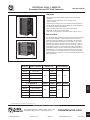
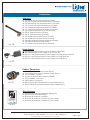
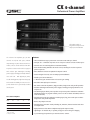
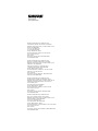
SECTIONAL WALL CABINETS
Standard Series 19" Wall Cabinets
300 Series Racks
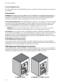
FEATURES
• Sturdy wall-mount cabinet protects equipment and saves valuable
floor space
• Selection includes models with 12" and 15" deep center
mounting sections
• Reinforced frame flanges, plus corner-brace structural supports and
electric-welded seams & miters provide stability for mounted equipment
• Punched vents assure heat dissipation
• Wire management provisions allow organized wire access
• Adjustable mounting rails provide flexibility
• New cutout on rear section on all models except 7 RU and 10 RU
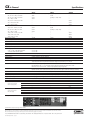
APPLICATIONS
The 300 Series cabinets have been engineered to provide full functional
and mechanical flexibility for wall-mounting standard 19" wide rack
equipment. Sectional assemblies may be installed to accommodate
right or left-hand hinging applications, and are ideal for use in areas
with limited floor space or "protected" access requirements. Units are
commonly used to house electronic switching, monitoring, sound, and
communication controls in school auditoriums, health care facilities,
presentation/conference centers, manufacturing facilities, laboratories,
public buildings, and recreational complexes. They can also be used
to house computer control equipment, studio electronics, and building
management/security systems in commercial, industrial, institutional, and
military applications.
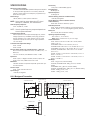
324-12
324-15
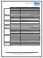
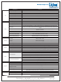
PANEL OPENING*
12" CTR MODELS
307-12
12 ⁄8" (7 RU)
310-12
17 ⁄8" (10 RU)
CABINET O.D.
WIDTH
316-12
281⁄8" (16 RU)
324-12
42 ⁄8" (24 RU)
310-15
175⁄8" (10 RU)
312-15
211⁄8" (12 RU)
41⁄2"
12"
REAR
CENTER
41⁄2"
15"
201⁄2"
5
20 ⁄8"
24"
31"
45"
1
15" CTR MODELS
CENTER
1
5
211⁄8" (12 RU)
REAR
15 ⁄4"
3
312-12
HEIGHT
SECTION DEPTH
WIDTH
HEIGHT
201⁄2"
TEN
W/DOOR
24"
5
20 ⁄8"
316-15
281⁄8" (16 RU)
324-15
421⁄8" (24 RU)
45"
335-15
613⁄8" (35 RU)
641⁄4"
31"
* Listed panel opening allows 1⁄16" clearance at top and bottom (1⁄8" total)
Specifications subject to change without notice
1601 JACK MCKAY BLVD. / ENNIS, TEXAS 75119 U.S.A.
TELEPHONE: (800) 876-3333 / FAX (800) 765-3435
AtlasSound.com
399
© 2007 Atlas Sound
Printed in U.S.A.
000905
ATS002120 RevB 4/07
SL10-1098
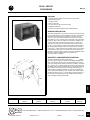
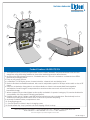
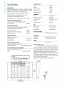
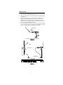
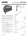
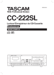
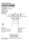
Fig. 1:Rear Section Mounting Holes
Knockouts
(Note: -61 Models have 8 mounting holes)
20.82
16.00
MOUNTING
HOLES
4.00
MOUNTING
HOLES
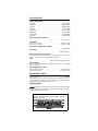
GENERAL DESCRIPTION
The 300 Series wall cabinets are distinguished by center-section depths of 12" and 15", respectively.
Basic model includes three, 16-gauge CRS sections which include a 2" deep, solid-steel front door,
a 12" or 15" deep center section with adjustable mounting rails, and a 41⁄2" deep rear door. Panel
space openings range from 7 RU to 35 RU (depending on series - see chart on page 1). Enclosures
are equipped with convenient and useful provisions for custom cabinet mounting, wire management,
equipment mounting, and structural support (see below for detailed information). Cabinet is finished
in #962 black epoxy.
Mounting Provisions
Mounting holes, located on the back panel of the rear door, enable the pre-assembled cabinet to
be easily secured to a wall, post, support, or other surfaces for elevated applications (see Fig.1)
These convenient cabinets are designed for right-hand hinging applications, but assemblies
can be inverted 180˚ to facilitate left-hand hinging. Rear section hinges are bolted, not welded,
to ensure easy retrofit capability. The removable pin-type hinges holding the center and rear
sections together facilitate independent pre-installation of the rear section. This feature also
permits efficient surface or recess installation. Models with panel heights of 7 RU, 10 RU and
12 RU have two hinges, while 16 RU, 24 RU and 35 RU panel space cabinets each have three
hinges. Rear sections are now equipped with a 121⁄2" x 121⁄2" square cutout (12 RU, 16 RU, 24 RU
and 35 RU panel height models).
4.00
MOUNTING
HOLES
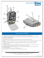
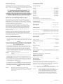
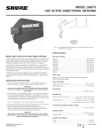
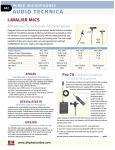
Fig. 2: Rear Section Featuring Optional
Subplate (by others) and Guide Plate
BOSS DETENTS
FACILITATE FIELD
INSTALLATION
OF A PLYWOOD,
ALUMINUM, OR
STEEL SUBPLATE
(BY OTHERS)
FOR MOUNTING
ACCESSORIES.
Equipment Mounting & Wiring
All models include one pair of 11-ga. adjustable front-to-rear mounting rails which are tapped
10–32, and manufactured to standard E.I.A. 5⁄8"–5⁄8"–1⁄2" spacing. Models with panel space
openings of 16 RU, 24 RU and 35 RU are equipped with center section mounting rail supports (1
per side) which have slotted cutouts for infinite mounting rail adjustments and open raceways to
hold vertically run wire and cable. Smaller models do not require mounting rail supports. Corner
brace supports, which straddle the back and side panel of the rear section (hinge side), also
feature round (11⁄4" dia.) wire access holes for harnessing excess wire. The back panel of the rear
section is equipped with 1⁄4" deep boss detents which give contractors field flexibility to screwmount a plywood, aluminum, or steel subplate (not made by Atlas) for mounting accessories
such as transformers, power strips, and phone relay systems inside the cabinet. Boss detents
are on 12" centers and vary depending upon model height (10 RU, 12 RU and 16 RU panel
space models have four detents 2 RU panel space models have six detents and 35 RU panel
space models have eight detents (see Fig. 2). Note: Model 307-12 does not have provisions for
mounting subplate.
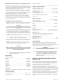
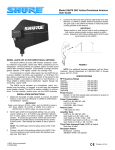
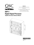
Conduit Knockouts
The 300 Series models have 20 conduit knockouts on the rear section, with the exception of the
307-12 which has 16. Conduit arrays are located at the top and bottom of the back panel (except
307-12 which has a centered array), as well as on the top and bottom back flanges. Panel arrays
consist of four knockouts: two 1" (25mm) standard and two 1⁄2" (13mm) / 3⁄4" (19mm) concentric. Top
and bottom flange arrays are comprised of six knockouts: three 1" (25mm) standard and three 1⁄2"
(13mm) / 3⁄4" (19mm) (See Fig. 3).
Guide
Plate for
Center
Section
Specifications subject to change without notice
1601 JACK MCKAY BLVD. / ENNIS, TEXAS 75119 U.S.A.
TELEPHONE: (800) 876-3333 / FAX (800) 765-3435
© 2007 Atlas Sound
Printed in U.S.A.
000905
AtlasSound.com
ATS002120 RevB 4/07
SL10-1098
Fig. 3: Rear Section Top & Bottom Flange
Conduit Knockout Array
.50-.75 COMBO
KNOCKOUT
1" KNOCKOUT
2.88
1.50
4.50
Ventilation
Stamped perforated vents, located on both sides (top and bottom) of the center section,
provide maximum ventilation for rack-mounted electronics (four vent patterns per side on 12" deep
series, eight per side on 15" deep.)
Structural Support
Series 300 cabinets offer exceptional structural support. The units' one-piece front and rear sections
are strengthened with frame flanges on bottom, top, and sides. Center sections also have "L"shaped gussets (brackets) which are plug-welded, joining bottom and top panels to side panels.
Series 3xx-12 and 3xx-15 have a total of 8 & 12 brackets, respectively. Rear sections have corner
brace supports which bridge the back and side panel (hinge side) giving the back (mounted) panel
extra reinforcement for tension relief (see Fig. 3). Units also have electric-welded seams and miters
which bolster the cabinets' overall bonding. The center section offers maximum reinforcement
provisions, such as a uniquely designed center section guide plate that reduces potential sagging by
distributing cabinet and equipment weight to rear section. The 11-ga., 1-7⁄8" wide guide plate, which
mounts to the rear section's bottom flange, provides a 3⁄4" lip for added support to the center section
when the cabinet is open or closed. The plate also ensures that an equipment-weighted center
section will close properly, by "guiding" alignment pins into respective holes.
CT31A. This optional heavy-duty caster support reduces the load bearing requirements of
the wall by supporting the center section weight when opened and closed (typically used
on 35 RU panel space models). Cabinet must be mounted 6" from the ground. Support
is constructed of formed, 14-ga. CRS and includes heavy-duty, zinc-plated caster with a
black, hard-tread wheel. The caster adjusts in height from 51⁄2" to 71⁄2" and is supplied with
drilling template for easy installation. Finished in black (Note: before installing the CT31A,
the center section guide plate must be removed) (Only one CT31A required per cabinet).
ARCHITECT AND ENGINEER SPECIFICATIONS
Center section shall be secured with screw-type locking rods and
alignment pins. The center section shall be equipped with adjustable,
front-to-rear mounting rails tapped with 10–32 holes on E.I.A. 19"
spacing. Units shall have slotted rail supports for mounting rail
adjustment and wire management purposes. Standard front door shall
be 2" (51mm) deep, and constructed of one-piece 16-ga. CRS, with
perforation vents and cylinder lock.
TEN
The sectional wall mounting cabinet shall be Atlas Sound Model __.
It shall be constructed of 16-gauge CRS throughout. Hinges shall be
bolted, not welded. All sections shall be of one-piece construction
with electric-welded seams and miters. Cabinet shall have provisions
which allow the unit to be inverted for accommodating left-hand
hinging applications. Rear section shall have concentric 1⁄2" (13mm)
and 3⁄4" (19mm) knockouts on the top and bottom surface panel, as
well as the flange panels at the top and bottom of the rear panel.
Specifications subject to change without notice
1601 JACK MCKAY BLVD. / ENNIS, TEXAS 75119 U.S.A.
TELEPHONE: (800) 876-3333 / FAX (800) 765-3435
AtlasSound.com
401
© 2007 Atlas Sound
Printed in U.S.A.
000905
ATS002120 RevB 4/07
SL10-1098
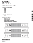
INSTALLATION
Fig. 6: Minimum mounting space required to facilitate
opening center section 90° with front door closed.
Fig. 5: Minimum mounting space required to facilitate
opening center section 90° with front door open.
12
35-1/4" 30015
38-1/4" 300- ace)
g Sp
in. Mountin
12
54-1/8" 30015
57-1/4" 300- ace)
Sp
g
in. Mountin
(M
(M
A
B
C
D
6"
E
A) Mounting Rail Supports
Installation Placement Considerations
B) Corner Brace Supports
• Determine left/right swing distance to adjacent walls.
C) Adjustable Front-to-Back Mounting Rails
(Standard E.I.A. Spacing)
D) Center Section Guide Plate
E) Optional Model CT31A Caster Support
(Requires the cabinet to be mounted 6" from the floor.)
• Decide if optional caster support Model CT31A will be
used to reduce wall load-bearing requirements
(recommended on 35 RU and some 24 RU panel
space cabinet installations). If the caster will be used,
cabinet must be mounted 6" from the floor.
Specifications subject to change without notice
1601 JACK MCKAY BLVD. / ENNIS, TEXAS 75119 U.S.A.
TELEPHONE: (800) 876-3333 / FAX (800) 765-3435
© 2007 Atlas Sound
Printed in U.S.A.
000905
AtlasSound.com
ATS002120 RevB 4/07
SL10-1098
WALL MOUNT
ENCLOSURE
600-12
FEATURES
• 16 Gauge CRS all welded construction with 11guage CRS
tapped mounting rails
• Locking front door
• Vents on each side
• 10-32 pan head screws for panel mounting
• Completely assembled
• Convenient Pre-Punched Back Panel for Wall Mounting
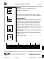
GENERAL DESCRIPTION
Atlas Sound Model 600-12 is a surface mounting wall cabinet used for
housing small electronic system installations including 19" wide amplifiers, tuners and associated communication controls for schools,
churches, clubs and recreation facilities. The 600-12 has a vertical
panel opening of 123⁄8" (314mm) and is constructed of 16 gauge CRS.
Louvers on each side of the cabinet are provided for ventilation. The
11 gauge CRS panel mounting rails are recessed 5⁄8" (16mm) for a
“flush” look. Locking front door is standard. Panel-mounting screws
(10-32 x 3⁄4") are provided for equipment panel and accessory mounting. Mounting rails are tapped 10-32 on EIA spacing.Three double 1⁄2"
(13mm) and 3⁄4" (19mm) knockouts are provided on the top and bottom
of the cabinet for wire entry. Four keyhole slots for wall hanging are
provided on the back panel. The 600-12 is shipped completely assembled and is finished in (#962) black epoxy powder coat.
UL Listed version is available.
ARCHITECT & ENGINEER SPECIFICATIONS
⁄ "
22
⁄"
38
5 16
15
1 ⁄4"
22
151⁄2"
123⁄8"P.S.
5 ⁄16"
19 S.
P.
The wall mounted cabinet shall be Atlas Sound __________ (Model
600-12) or approved equal. It shall be constructed of 16 gauge CRS
with 11 gauge CRS mounting rails. The cabinet shall have a locking
front door. Internal louvers shall be provided for ventilation. Three double 1⁄2" (13mm) and 3⁄4" (19mm) knockouts shall be provided on the top
and bottom of the cabinet to facilitate wiring. Four keyhole slots shall
be provided on the back panel to accommodate wall hanging. The
cabinet shall accommodate standard 19" (483mm) rack panels and
have a vertical panel opening of 123⁄8" (314mm). The cabinet shall be
provided with twelve 10-32 x 3⁄4" (19mm) panel mounting screws and
the mounting rail shall be tapped 10-32 on EIA spacing. Enclosure
shall be shipped completely assembled.
TEN
153⁄8"
MODEL
600-12
WIDTH
225⁄16"
(567mm)
HEIGHT
151⁄2"
(394mm)
DEPTH
153⁄8"
(391mm)
PANEL SPACE
123⁄8"
(314mm)
WEIGHT
45 lbs.
(20.41 kg)
Specifications subject to change without notice
1601 JACK MCKAY BLVD. / ENNIS, TEXAS 75119 U.S.A. / TELEPHONE: (800) 876-3333 / FAX (800) 765-3435
401
© 2001 Atlas Sound LP
Printed in U.S.A.
000501
SL10-1226
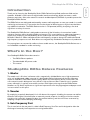
DESK AND BANQUET STANDS
DS Series
FEATURES
• Versatile Stands Fulfill Functional and Aesthetic Miking Requirements for
Microphone Placement
• Quality Construction Assures Extended Service and Quality Appearance
• Weighted Bases Provide Maximum Stability
APPLICATIONS
Atlas Sound microphone stands meet functional and aesthetic requirements for microphone
support and placement within contemporary and traditional decors. The extensive selection
includes models for use on banquet and meeting room consoles, court room and dispatcher
desks, sports/recreation booths, church pulpits, and telephone switchboards. High-stability units
are also suited for application in various sound reinforcement systems, as well as broadcast
and recording studios.
DS2
GENERAL DESCRIPTION
Atlas Sound brand microphone desk stands assure optimum stability and "like new" appearance
for many years of service. Chrome and ebony finished bases are attractively styled and
present a quality appearance for traditional and contemporary decors. Microphone placement
and positioning is enhanced by the "locking nut" feature which securely fastens adapters and
holders to the desk stands. The seamless tubing is 5⁄8" cold rolled steel and terminates in the
industry standard 5⁄8" - 27 thread pattern for use with microphone accessories. Fixed-height
stand selection includes Models DS2, DS5(E), and DS14. Adjustable-height stand Model
DS7(E) features the wearproof, Atlas Sound grip-action clutch for positive locking control.
DS5
DS2. Low silhouette stand features an integral tension variable mount to reduce conductivity of
external mechanical vibrations. High-stability, die-cast metal base with protective pads includes
notched area for convenient placement of cards or pens. Fixed-height tubing is chrome plated.
Base is supplied in non-reflective ebony.
DS5/DS5E. Fixed-height stands include traditional, circular cast iron base and chrome-plated
tubing for application with any standard microphone. DS5 features chrome plated tubing, DS5E
is finished in ebony epoxy.
DS7(E)
DS7/DS7E. Versatile stands may be adjusted from 8" to 13" and include a grip-action clutch
and ebony-finished cast iron base. DS-7 features chrome-plated tubing; DS7E is supplied with
non-reflective ebony tubing.
DS14. Professionally styled stand includes die-cast "wishbone" shaped base. Finished in ebony
and features 3" high chrome tubing.
MODEL
DS2
DS5
DS5E
DS7
DS7E
DS14
BASE
6" L x 4" W
6" Dia.
6" Dia.
6" Dia.
6" Dia.
Wishbone
STAND HEIGHT
4"
5"
5"
8" - 13"
8" - 13"
3"
BASE MATERIAL
Cast Zinc
Cast Iron
Cast Iron
Cast Iron
Cast Iron
Cast Iron
BASE FINISH
Ebony
Ebony
Ebony
Ebony
Ebony
Ebony
TUBE FINISH
Chrome
Chrome
Ebony
Chrome
Ebony
Chrome
WEIGHT
2 lbs. (1 kg)
3 lbs. (1.4 kg)
3 lbs. (1.4 kg)
3 lbs. (1.4 kg)
3 lbs. (1.4 kg)
2 lbs. (1 kg)
ELEVEN
DS14
Specifications subject to change without notice
1601 JACK MCKAY BLVD. / ENNIS, TEXAS 75119 U.S.A.
TELEPHONE: (800) 876-3333 / FAX (800) 765-3435
AtlasSound.com
487
© 2006 Atlas Sound LP
Printed in U.S.A.
ATS002523 RevB 10/06
SL11-1396
MS-10C
MS-10CE
ALL-PURPOSE MICROPHONE FLOOR STANDS
FEATURES
• Economical, Industry Standard Floor Stands Suitable for a Variety of Applications
• Wearproof, Three-Piece Clutch Offers Secure, Fast, and Noise-Free
Height Adjustment
• Edge-Concentrated, One-Piece Circular Base Ensures Maximum Stability
• Available in Choice of Chrome or Non-Reflective Ebony Epoxy Finish
• Field Serviceable Parts Guarantee Long Product Life
Steel tubing is finished in a
choice of mirrored chrome or
non-reflective ebony epoxy (E).
Atlas Sound stands are threaded
5
⁄8"-27 and include a lock-nut
ring for versatile positioning
of accessories.
Anti-vibration cap absorbs incidental vibrations and sounds.
Famous Atlas Sound clutch won't
slip under pressure. Three-piece
assembly is also field serviceable.
Lock-nut ring securely positions tubing to base.
Bases are high-stability cast metal
equipped with shock absorbing
rubber pads.
APPLICATIONS
MS-10C
Atlas Sound® brand microphone floor stand Models MS-10C/MS-10CE are the industry standard for application in schools, churches, recreation complexes, lounges, restaurants, conference areas, meeting rooms or wherever sound reinforcement or communications systems are
applied. Outstanding U.S. craftsmanship and high-quality materials are combined to make
these functional, full-height stands extremely stable and durable-serving as exceptional values
for performers and presenters.
GENERAL DESCRIPTION
MS-10C / MS-10CE. These all-purpose chrome and ebony finished stands, respectively, are
quality, long-lasting models which feature durable tubing, the famous Atlas Sound® wearproof
clutch, and a 10" dia. die cast circular base. The three-piece clutch provides positive locking
control and is able to withstand years of stage and studio handling. The base features edgeconcentrated weight distribution and is equipped with rubber pads to absorb shock and protect
floor surfaces.
HEIGHT
BASE
MODEL
SPAN
DIAMETER
MS-10C
35" - 63"
10"
MS-10CE (89 - 160 cm)
(25 cm)
TUBE
FINISH
Chrome
Ebony
BASE
FINISH
Ebony
Ebony
WEIGHT
9.0 lbs.
(4.1 kg)
MS-10CE
ELEVEN
The 5⁄8" and 7⁄8" dia. tubing is fully adjustable with a vertical extension ranging from 35" to 63".
Tubing is manufactured of cold rolled steel and terminates in the industry standard 5⁄8" - 27
thread suitable for microphone clamps and accessories (see reverse side). Top and bottom
lock-nut rings are included for versatile and secure positioning.
Model MS-10C is finished in chrome; Model MS-10CE is finished in ebony epoxy to eliminate
reflections caused by high-intensity lighting. This durable epoxy finish will withstand the rigors
of repeated use and frequent transportation.
Specifications subject to change without notice
1601 JACK MCKAY BLVD. / ENNIS, TEXAS 75119 U.S.A. / TELEPHONE: (800) 876-3333 / FAX (800) 765-3435
465
© 2001 Atlas Sound LP
Printed in U.S.A.
000501
SL11-1361
ACCESSORIES
BOOM ATTACHMENTS
BB-28X(E)
BB-77(E)
PB11X(E)
PB15(E)
PB21X(E)
PB25
PB25X
Adj. 26 1⁄4" - 383⁄4" Length, Chrome (Ebony)
Fixed 34" Length, Fixed 3⁄4 lb. Counterweight, Chrome (Ebony)
Adj. 16 1⁄4" – 24 1⁄2" Length, Fixed 3⁄4 lb. Counterweight, Chrome (Ebony)
Fixed 34" Length, Counterweight, Fixed 3⁄4-lb. Chrome (Ebony)
Adj. 25 1⁄4" – 38 1⁄2" Length, Fixed 3⁄4 lb. Counterweight, Chrome (Ebony)
Fixed, 34 1⁄2" Length, Adj. 2 lb. Counterweight, Chrome
Adj. 32" – 51 1⁄2" Length, Adj. 2 lb. Counterweight, Chrome
GOOSENECK FLEXIBLE EXTENSIONS (.338" I.D.)
GN-6(E)
GN-13(E)
GN-19(E)
6" L, Chrome (Ebony)
13" L, Chrome (Ebony)
19" L, Chrome (Ebony)
CLIP-MOUNTING MICROPHONE ACCESSORIES
LO-2B(E)
SO-1B
SW-1B
TM-1(E)
VM-2
Lock-On / Mic Clip Disconnect, Chrome (Ebony)
Snap-On / Mic Clip Disconnect, Chrome
Gyro-Microphone Swivel, Chrome
Twin Microphone Mount, Chrome (Ebony)
Compact, Shock Isolation Accessory, Chrome (replaces VM-1)
MULTI-PURPOSE CLAMPS
CO-1B
MAC-1
Adapter & Clamp, 5⁄8" -27, Max. Opening 7⁄8", Ebony
Adapter & Clamp, 5⁄8" -27, Max. Opening 1 1⁄2", Ebony
CABLE HANGERS & TUBE EXTENSIONS FOR USE WITH COUPLING ADAPTERS
CH-1B(E)
AD-7B
AD-8B
AD-14B
AD-19B
Cable / Tambourine Hanger, Chrome (Ebony)
3" Long Tube, 5⁄8"-27 Male Thread, Chrome Plated
6" Long Tube, 5⁄8"-27 Male Thread, Chrome Plated
90° Angle Tube, 5⁄8"-27 Male & Female Thread, Chrome Plated, 4"H x 4" Ext.
90° Angle Tube, 5⁄8"-27 Male & Female Thread, Chrome Plated, 6"H x 3" Ext.
REPLACEMENT KITS FOR MS-10C AND MS-10CE
MSC
MSCE
MSC-K
MSCE-K
MSAC-K
Chrome Tube Assembly (5⁄8" - 7⁄8") with Clutch
Ebony Tube Assembly (5⁄8" - 7⁄8") with Clutch
Clutch for Chrome Stands with 7⁄8" Dia. Tubing
Clutch for Ebony Stands with 7⁄8" Dia. Tubing
Miscellaneous Parts Kit with (1) Lock Ring,
(1) Anti-Vibration Cap, and (3) Rubber Base Pads
Specifications subject to change without notice
1601 JACK MCKAY BLVD. / ENNIS, TEXAS 75119 U.S.A. / TELEPHONE: (800) 876-3333 / FAX (800) 765-3435
© 2001 Atlas Sound LP
Printed in U.S.A.
000501
SL11-1361
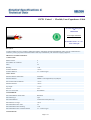
1217B Paired - Flexible, Low-Capacitance Cable
For more information please
call
1-800-Belden1
See Put-ups and Colors
Related Documents : No. 7 for
Snake Cables.pdf
Description:
22 AWG stranded (7x30) TC conductor, Datalene® insulation, individually shielded with Beldfoil® (100% coverage), numbered/colorcoded PVC jackets, pair jackets and shields bonded to both strip simultaneously with automatic stripping equipment.
PHYSICAL CHARACTERISTICS:
CONDUCTOR:
Number of Pairs
4
Total Number of Conductors
8
AWG
22
Stranding
7x30
Conductor Diameter
.030 in.
Conductor Material
TC - Tinned Copper
INSULATION:
Insulation Material Trade Name
Datalene®
Insulation Material
FHDPE - Foam High Density Polyethylene
Nom. Insulation Wall Thickness
.015 in.
Insulation Diameter
.060 in.
Lay Length
1.75 in.
Twists/ft.
6.85
Pair Color Code Chart
Red & Black
INNER SHIELD:
Inner Shield Material Trade Name
Beldfoil®
Inner Shield Type
Tape
Inner Shield Material
Aluminum Foil-Polyester Tape
Inner Shield % Coverage
100 %
Inner Shield Drain Wire AWG
22
Inner Shield Drain Wire Stranding
7x30
Inner Shield Drain Wire Conductor Material
TC - Tinned Copper
INNER JACKET:
Page 1 of 3
1217B Paired - Flexible, Low-Capacitance Cable
Inner Jacket Material
PVC - Polyvinyl Chloride
Inner Jacket Nominal Wall Thickness
.015 in.
Inner Jacket Diameter
.153 in.
Inner Jacket Color Code Chart :
Number
1
2
Color
Brown
Red
Number
3
4
OUTER JACKET:
Outer Jacket Material
PVC - Polyvinyl Chloride
Outer Jacket Nominal Wall Thickness
.040 in.
Outer Jacket Ripcord
Yes
OVERALL NOMINAL DIAMETER:
Overall Nominal Diameter
.458 in.
MECHANICAL CHARACTERISTICS:
Operating Temperature Range
-20°C To +60°C
Non-UL Temperature Rating
60°C
Bulk Cable Weight
88.8 lbs/1000 ft.
Max. Recommended Pulling Tension
109 lbs.
Min. Bend Radius (Install)
4.58 in.
APPLICABLE SPECIFICATIONS AND AGENCY COMPLIANCE:
APPLICABLE STANDARDS:
EU CE Mark (Y/N)
Yes
EU RoHS Compliant (Y/N)
Yes
EU RoHS Compliance Date (mm/dd/yyyy):
01/01/2004
PLENUM/NON-PLENUM:
Plenum (Y/N)
N
ELECTRICAL CHARACTERISTICS:
Nom. Inductance
.20 µH/ft
Nom. Capacitance Conductor to Conductor @ 1 KHz
19 pF/ft
Nom. Cap. Cond. to Other Cond. & Shield @ 1 KHz
35 pF/ft
Nominal Velocity of Propagation
78 %
Nom. Conductor DC Resistance @ 20 Deg. C
15 Ohms/1000 ft
Ind. Pair Nominal Shield DC Resistance @ 20 Deg. C
10.6 Ohms/1000 ft
Max. Operating Voltage - Non-UL
150 V RMS, 300 V RMS
Max. Recommended Current
2 Amps per conductor @ 20°C
NOTES:
Page 2 of 3
Color
Orange
Yellow
1217B Paired - Flexible, Low-Capacitance Cable
Notes
Datalene® insulation features include a low dielectric constant and a low dissipation
factor for high-speed, low distortion data handling. Physical properties include
good crush resistance and light weight. Pair jackets and shields are bonded so both
strip simultaneously with automatic stripping equipment.
PUT-UPS AND COLORS:
Item
Description
1217B B591000
4 PR #22 FHDPE FS
PVC PVC
1217B B59500
4 PR #22 FHDPE FS
PVC PVC
Put-Up (ft.)
1000
Ship Weight (lbs.)
107
Jacket Color
BLACK, MATTE
Notes
C
500
53
BLACK, MATTE
C
C = CRATE REEL PUT-UP.
Revision Number: 1
Revision Date: 08-11-2005
© Copyright 2006 Belden, Inc
All Rights Reserved.
Although Belden ("Belden") makes every reasonable effort to ensure their accuracy at the time of this publication, information and
specifications described herein are subject to error or omission and to change without notice, and the listing of such information and
specifications does not ensure product availability.
Belden provides the information and specifications herein on an "AS IS" basis, with no representations or warranties, whether express,
statutory or implied. In no event will Belden be liable for any damages (including consequential, indirect, incidental, special, punitive, or
exemplary damages) whatsoever, even if Belden has been advised of the possibility of such damages, whether in an action under contract,
negligence or any other theory, arising out of or in connection with the use, or inability to use, the information or specifications described
herein.
All sales of Belden products are subject to Belden's standard terms and conditions of sale.
Belden believes this product to be in compliance with the following environmental regulations: California Proposition 65 Consent Judgment
For Wire & Cable Mfgs.(San Francisco Superior Court Nos. 312962 And 320342); EU RoHS (Directive 2002/95/EC, 27-Jan2003);Material manufactured prior to the compliance date may still be in stock at Belden facilities and in our Distributor's inventory. EU
ELV (Directive 2000/53/EC, 18-Sept-2000); EU WEEE (Directive 2002/96/EC, 27-Jan-2003); And EU BFR (Directive 2003/11/EC, 6-Feb2003). The information provided in this Product Disclosure, and the identification of materials listed as reportable or restricted within the
Product Disclosure, is correct to the best of Belden's knowledge, information and belief at the date of its publication. The information
provided in the Product Disclosure is designed only as a general guide for the safe handling, storage, and any other operation of the product
itself or the one that it becomes a part of. This Product Disclosure is not to be considered a warranty or quality specification. Regulatory
information is for guidance purposes only. Product users are responsible for determining the applicability of legislation and regulations
based on their individual usage of the product.
Belden declares this product to be in compliance with EU LVD (Low Voltage Directive 73/23/EEC), as amended by directive 93/68/EEC.
Page 3 of 3
Detailed Specifications & Technical Data
ENGLISH MEASUREMENT VERSION
1311A Multi-Conductor - Speaker Cable
Description:
12 AWG stranded (7x24x34) high-conductivity bare copper conductors, PO insulation, PVC jacket.
Sequential footage marking every two feet.
Usage (Overall)
Suitable Applications:
Speaker Cable, Direct Burial, Indoor/Outdoor Home Theater, In-Wall Speaker,
Outdoor Speaker
Physical Characteristics (Overall)
Conductor
AWG:
# Conductors AWG Stranding Conductor Material
2
12
7x24x34
Dia. (in.)
High Conductivity BC - Bare Copper .102
Insulation
Insulation Material:
Insulation Material Dia. (in.)
PO - Polyolefin
.140
Outer Shield
Outer Shield Material:
Outer Shield Material
Unshielded
Outer Jacket
Outer Jacket Material:
Outer Jacket Material
PVC - Polyvinyl Chloride
Overall Cabling
Overall Cabling Color Code Chart:
Number Color
1
Black
2
Red
Overall Nominal Diameter:
0.352 in.
Mechanical Characteristics (Overall)
Operating Temperature Range:
-20°C To +75°C
UL Temperature Rating:
75°C
Bulk Cable Weight:
64.900 lbs/1000 ft.
Max. Recommended Pulling Tension:
152 lbs.
Min. Bend Radius (Install)/Minor Axis:
3.500 in.
Applicable Specifications and Agency Compliance (Overall)
Applicable Standards & Environmental Programs
NEC/(UL) Specification:
CL3,CM
CEC/C(UL) Specification:
CM
Page 1 of 3
Detailed Specifications & Technical Data
ENGLISH MEASUREMENT VERSION
1311A Multi-Conductor - Speaker Cable
EU Directive 2000/53/EC (ELV):
Yes
EU Directive 2002/95/EC (RoHS):
Yes
EU RoHS Compliance Date (mm/dd/yyyy):
07/01/2005
EU Directive 2002/96/EC (WEEE):
Yes
EU Directive 2003/11/EC (BFR):
Yes
CA Prop 65 (CJ for Wire & Cable):
Yes
MII Order #39 (China RoHS):
Yes
Flame Test
UL Flame Test:
UL1581 Vertical Flame and FT-1 Flame Test
CSA Flame Test:
FT1
Suitability
Suitability - Indoor:
Yes
Suitability - Outdoor:
Yes
Plenum/Non-Plenum
Plenum (Y/N):
No
Plenum Number:
6000UE
Electrical Characteristics (Overall)
Nom. Inductance:
Inductance (µH/ft)
.15
Nom. Capacitance Conductor to Conductor:
Capacitance (pF/ft)
22.3
Nominal Velocity of Propagation:
VP (%)
66
Nom. Conductor DC Resistance:
DCR @ 20°C (Ohm/1000 ft)
1.6
Max. Operating Voltage - UL:
Voltage
300 V RMS
Max. Recommended Current:
Current
17 Amps per conductor @ 25°C
Put Ups and Colors:
Item #
Putup
Ship Weight
Color
Notes
Item Desc
1311A 0081000
1,000 FT
74.000 LB
GRAY
C
2 #12 PE FRPVC
1311A 008500
500 FT
36.500 LB
GRAY
C
2 #12 PE FRPVC
1311A 0101000
1,000 FT
74.000 LB
BLACK
C
2 #12 PE FRPVC
1311A 010500
500 FT
36.500 LB
BLACK
C
2 #12 PE FRPVC
1311A 1SL1000
1,000 FT
74.000 LB
WHITE 1SL
C
2 #12 PE FRPVC
1311A 1SL500
500 FT
36.500 LB
WHITE 1SL
C
2 #12 PE FRPVC
Notes:
C = CRATE REEL PUT-UP.
Page 2 of 3
B R I L L I A N C E®
B R O A D C A S T
C A B L E S
19.36
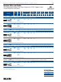
Speaker Wire and Cable
Low-Capacitance Oxygen-Free, High-Conductivity (OFHC) Speaker Cable
Twisted Jacketed Construction
Description
Part
No.
UL NEC/
C(UL) CEC
Type
Standard Lengths
No.
of
Cond.
Ft.
m
Standard
Unit Weight
Lbs.
kg
Insulation
Thickness
Inch
mm
Jacket
Thickness
Inch
mm
Nominal OD
Inch
mm
Nominal
Capacitance*
pF/Ft.
pF/m
Low Cap • 16 AWG Stranded (65x34) Oxygen-free High-Conductivity Bare Copper Conductors • Conductors Cabled • Unshielded
Polyolefin Insulation • PVC Jacket (Available in Black, White, Gray, Blue or Green)
1307A
NEC:
2
U-500
U-152.4
15.0
6.8
.013
u
1000 †
304.8
29.0
13.2
U-500
1000 †
U-152.4
304.8
26.5
54.0
12.0
24.5
CMR, CL3R
CEC:
CMG FT4
.32
.022
.56
.210
5.33
19.9
65.3
.32
.026
.66
.270
6.86
19.9
65.3
Suitable for Direct Burial applications. White and Black jackets are Sunlight-resistant.
1308A
u
NEC:
CMR, CL3R
CEC:
CMG FT4
4
.013
Suitable for Direct Burial applications. White and Black jackets are Sunlight-resistant.
Low Cap • 14 AWG Stranded (105x34) Oxygen-free High-Conductivity Bare Copper Conductors • Conductors Cabled • Unshielded
Polyolefin Insulation • PVC Jacket (Available in Black, White, Gray, Blue or Green)
1309A
NEC:
2
U-500
U-152.4
22.5
10.2
.016
For Audio Use Only
u
1000 †
304.8
46.0
20.9
U-500
1000 †
U-152.4
304.8
41.5
84.0
18.8
38.1
CMR, CL3R
CEC:
CMG FT4
.39
.027
.69
.264
6.71
20.5
67.3
.39
.033
.94
.319
8.10
20.5
67.3
Suitable for Direct Burial applications. White and Black jackets are Sunlight-resistant.
For Audio Use Only
1310A
u
NEC:
CMR, CL3R
CEC:
CMG FT4
4
.016
Suitable for Direct Burial applications. White and Black jackets are Sunlight-resistant.
Low Cap • 12 AWG Stranded (168x34) Oxygen-free High-Conductivity Bare Copper Conductors • Conductors Cabled • Unshielded
Polyolefin Insulation • PVC Jacket (Available in Black, White or Gray)
1311A
NEC:
2
U-500
U-152.4
36.5
For Audio Use Only
u
CMR, CL3R
CEC:
CMG FT4
.46
.036
152.4
304.8
36.5
74.0
16.6
16.6
33.6
.018
500
1000 †
.91
500
1000 †
152.4
304.8
66.5
132.0
30.2
59.9
.018
.46
.043 1.09
.352
8.94
22.3
73.2
.423 10.74
22.3
73.2
23.2
76.1
Suitable for Direct Burial applications. White and Black jackets are Sunlight-resistant.
For Audio Use Only
1312A
u
NEC:
CMR, CL3R
CEC:
CMG FT4
4
Suitable for Direct Burial applications. White and Black jackets are Sunlight-resistant.
Low Cap • 10 AWG Stranded (259x34) Oxygen-free High-Conductivity Bare Copper Conductors • Conductors Cabled
Polyolefin Insulation • PVC Jacket (Available in Black, White or Gray)
1313A
NEC:
2
500
152.4
55.0
For Audio Use Only
u
CMR, CL3R
CEC:
CMG FT4
1000 †
304.8
109.0
25.0
49.5
.019
.48
.044 1.12
.428 10.87
Suitable for Direct Burial applications. White and Black jackets are Sunlight-resistant.
OFHC = Oxygen-Free High-Conductivity
*Capacitance between conductors.
†1000
ft. put-ups not available in Blue or Green.
Color Code Chart
Cond.
1
2
3
4
Color
Black
Red
White
Green
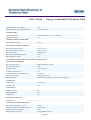
7919A Paired - Category 5e DataTuff® Twisted Pair Cable
For more information please
call
1-800-Belden1
See Put-ups and Colors
Related Documents :
Termination Instructions for
Shielded UTP.pdf
Description:
24 AWG solid bare copper conductors, twisted pairs, polyolefin insulation, overall Beldfoil shield (100% coverage), 24 AWG stranded TC
drain wire, industrial grade sunlight- and oil-resistant PVC jacket, rip cord. Sequential marking at two foot intervals
SUITABLE APPLICATIONS:
Suitable Applications
Industrial Ethernet Cable, Harsh Environments, 100MHz Category 5e, Gigabit
Ethernet, 100BaseTX, 100BaseVG ANYLAN, 155ATM, 622ATM, NTSC/PAL
Component or Composite Video, AES/EBU Digital Audio, RS-422, CMX Outdoor, RJ-45 Compatible, Noisy Environments
PHYSICAL CHARACTERISTICS:
CONDUCTOR:
Number of Pairs
4
Total Number of Conductors
8
AWG
24
Stranding
Solid
Conductor Material
BC - Bare Copper
INSULATION:
Insulation Material
PO - Polyolefin
Nom. Insulation Wall Thickness
.010 in.
Pair Color Code Chart :
Number
1
2
Color
White/Blue Stripe & Blue
White/Orange Stripe & Orange
Number
3
4
OUTER SHIELD:
Outer Shield Material Trade Name
Beldfoil®
Outer Shield Type
Tape
Outer Shield Material
Aluminum Foil-Polyester Tape
Outer Shield %Coverage
100 %
OUTER SHIELD DRAIN WIRE :
Outer Shield Drain Wire AWG
24
Page 1 of 4
Color
White/Green Stripe & Green
White/Brown Stripe & Brown
7919A Paired - Category 5e DataTuff® Twisted Pair Cable
Outer Shield Drain Wire Stranding
7x32
Outer Shield Drain Wire Conductor Material
TC - Tinned Copper
OUTER JACKET:
Outer Jacket Material
Industrial Grade PVC - Polyvinyl Chloride
Outer Jacket Ripcord
No
OVERALL NOMINAL DIAMETER:
Overall Nominal Diameter
.265 in.
MECHANICAL CHARACTERISTICS:
Operating Temperature Range
-40°C To +75°C
Installation Temperature Range
-25°C To +75°C
Bulk Cable Weight
30 lbs/1000 ft.
Max. Recommended Pulling Tension
25 lbs.
Min. Bend Radius (Install)
1 in.
APPLICABLE SPECIFICATIONS AND AGENCY COMPLIANCE:
APPLICABLE STANDARDS:
NEC/(UL) Specification
CMR, CMX-Outdoor, UL444
CEC/C(UL) Specification
CMR
IEC Specification
11801 Category 5
EU RoHS Compliant (Y/N)
Yes
EU RoHS Compliance Date (mm/dd/yyyy):
01/01/2004
TIA/EIA Specification
568-B.2 Category 5e
Other Specification
NEMA WC-63.1 Category 5e, UL verified to Category 5e
FLAME TEST:
UL Flame Test
UL1666 Riser
CSA Flame Test
FT4
SUITABILITY:
Suitability - Outdoor
Yes
Sunlight Resistance
Yes
Oil Resistance
Yes
PLENUM/NON-PLENUM:
Plenum (Y/N)
N
ELECTRICAL CHARACTERISTICS:
Nom. Mutual Capacitance @ 1 KHz
15 pF/ft
Maximum Capacitance Unbalance (pF/100 m)
330 pF/100 m
Nominal Velocity of Propagation
70 %
Maximum Delay (ns/100 m)
538 @ 100MHz ns/100 m
Page 2 of 4
7919A Paired - Category 5e DataTuff® Twisted Pair Cable
Maximum Delay Skew (ns/100m)
45 ns/100 m
Maximum Conductor DC Resistance @ 20 Deg. C
9.38 Ohms/100 m
Maximum DCR Unbalance @ 20 Deg. C
3%
Max. Operating Voltage - UL
300 V RMS
ELECTRICAL CHARACTERISTICS - PREMISE:
Premise Cable Electricals Table 1 :
Frequency
(MHz)
Max.
Attenuation
(dB/100 m)
Min. NEXT
(dB)
Min. PSNEXT Min. ACR (dB) Min. PSACR
(dB)
(dB)
Min. Return
Loss (dB)
1
4
8
10
16
20
25
31.25
62.5
100
2.0
4.1
5.8
6.5
8.2
9.3
10.4
11.7
17.0
22.0
65.3
56.3
51.8
50.3
47.3
45.8
44.3
42.9
38.4
35.3
62.3
53.3
48.8
47.3
44.3
42.8
41.3
39.9
35.4
32.3
20.0
23.0
24.5
25.0
25.0
25.0
24.3
23.6
21.5
20.1
63.0
51.0
46.0
43.0
39.0
36.5
33.9
31.0
22.0
14.0
60.0
49.0
43.0
41.0
36.0
33.5
30.9
28.0
19.0
11.0
Min.
Structural
Return Loss
(dB)
23
23.0
24.5
25.0
25.0
25.0
24.3
23.6
21.5
20.1
Premise Cable Electricals Table 2 :
Frequency (MHz)
1
4
8
10
16
20
25
31.25
62.5
100
Input (Unfitted)
Impedance (Ohms)
100 ± 15
100 ± 15
100 ± 15
100 ± 15
100 ± 15
100 ± 15
100 ± 15
100 ± 15
100 ± 15
100 ± 15
Fitted Impedance
(Ohms)
100 ± 15
100 ± 15
100 ± 15
100 ± 15
100 ± 15
100 ± 15
100 ± 15
100 ± 15
100 ± 15
100 ± 15
Min. ELFEXT (dB)
Min. PSELFEXT (dB)
63.8
51.7
45.7
43.8
39.7
37.7
35.8
33.9
27.8
23.8
60.8
48.7
42.7
40.8
36.7
34.7
32.8
30.9
24.8
20.8
NOTES:
Notes
Operating temperatures are subject to length de-rating. Cable passes -40°C Cold
Bend per UL 1581.
PUT-UPS AND COLORS:
Item
Description
Put-Up (ft.)
7919A 0061000
4 PR #24 PP FS PVC 1000
Ship Weight (lbs.)
35
Jacket Color
BLUE, LIGHT
Notes
C
7919A 0101000
4 PR #24 PP FS PVC 1000
35
BLACK
C
7919A 0102000
4 PR #24 PP FS PVC 2000
68
BLACK
C
Page 3 of 4
7919A Paired - Category 5e DataTuff® Twisted Pair Cable
C = CRATE REEL PUT-UP.
Revision Number: 6
Revision Date: 07-12-2006
© Copyright 2006 Belden, Inc
All Rights Reserved.
Although Belden ("Belden") makes every reasonable effort to ensure their accuracy at the time of this publication, information and
specifications described herein are subject to error or omission and to change without notice, and the listing of such information and
specifications does not ensure product availability.
Belden provides the information and specifications herein on an "AS IS" basis, with no representations or warranties, whether express,
statutory or implied. In no event will Belden be liable for any damages (including consequential, indirect, incidental, special, punitive, or
exemplary damages) whatsoever, even if Belden has been advised of the possibility of such damages, whether in an action under contract,
negligence or any other theory, arising out of or in connection with the use, or inability to use, the information or specifications described
herein.
All sales of Belden products are subject to Belden's standard terms and conditions of sale.
Belden believes this product to be in compliance with the following environmental regulations: California Proposition 65 Consent Judgment
For Wire & Cable Mfgs.(San Francisco Superior Court Nos. 312962 And 320342); EU RoHS (Directive 2002/95/EC, 27-Jan2003);Material manufactured prior to the compliance date may still be in stock at Belden facilities and in our Distributor's inventory. EU
ELV (Directive 2000/53/EC, 18-Sept-2000); EU WEEE (Directive 2002/96/EC, 27-Jan-2003); And EU BFR (Directive 2003/11/EC, 6-Feb2003). The information provided in this Product Disclosure, and the identification of materials listed as reportable or restricted within the
Product Disclosure, is correct to the best of Belden's knowledge, information and belief at the date of its publication. The information
provided in the Product Disclosure is designed only as a general guide for the safe handling, storage, and any other operation of the product
itself or the one that it becomes a part of. This Product Disclosure is not to be considered a warranty or quality specification. Regulatory
information is for guidance purposes only. Product users are responsible for determining the applicability of legislation and regulations
based on their individual usage of the product.
Page 4 of 4
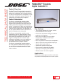
PANARAY®
402® Series II
Loudspeaker
General Description
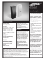
The Bose® 402 Series II loudspeaker
is a 120-watt speaker designed for
permanent installations and portable
use indoors and outdoors. As a new
addition to the Bose line of Installed
AnyWhere loudspeakers, it meets
our strict standards for outdoor use.
TM
The 402 Series II loudspeaker offers
the following features:
• Voice and music reproduction over
a broad dispersion area
Technical Information
Frequency Range
90Hz to 16kHz ±3dB
Sensitivity1
91dB-SPL @ 1W, 1m (pink noise)
Available colors: black or white
Connectors: Two (2) parallel-wired
NL4 connectors
Enclosure construction: Micareinforced polyethylene copolymer
structural foam
Maximum Acoustic Output
2
111dB-SPL @ 1m (pink noise)
115dB-SPL @ 1m (IEC3 noise)
Dispersion (–6dB point, average,
1-4kHz)
Horizontal 120˚
Vertical 60˚
Long-Term Power Handling4
120W continuous
Impedance
8Ω nominal
Mechanical Specifications
Dimensions: 23.25"H x 8.1"W x
7.25"D (59 cm H x 21 cm W x
18 cm D)
Weight: 15 lb (7 kg)
Installation
Installation and use instructions are
included with the loudspeaker.
The 402 Series II loudspeakers are
designed to be wall or ceiling
mounted, or mounted on stands for
portable use. The following versatile
accessories are available from Bose:
• WBP4 402 Wall Mount Bracket
(0-45˚ pitch, ± 60˚ yaw in vertical
orientation; ±28˚ in horizontal
orientation), black or white
• SB4 402 Speaker Single Fly
Bracket (0-45˚ pitch), black or
white
• SS10 Speaker Stand with Mounting Adapter and Carry Bag, black
• TK-402 Speaker Transit Kit, black
1
Full bandwidth pink noise is applied to the 402-II speaker and amplified to a level at the loudspeaker terminals corresponding to 1 watt as referenced to the nominal impedance. The average
sound pressure level (dB-SPL) is measured at 1 meter from the speaker in an anechoic environment.
2
Full bandwidth pink noise is applied to the 402-II speaker and amplified to a level at the loudspeaker terminals corresponding to the long-term rated power handling of the speaker. The average
sound pressure level (dB-SPL) is measured at 1 meter from the speaker in an anechoic environment.
3
Full bandwidth pink noise, meeting International Electrotechnical Commission (IEC) Standard
#268-5, with a spectrum corresponding to average program material.
4
Full bandwidth noise, meeting the IEC Standard #268-5 is applied to the 402-II speaker and
amplified to a level at the loudspeaker terminals corresponding to the power handling of the
loudspeaker. The loudspeaker must show no visible damage or measurable loss of performance
after 100 hours of continuous testing.
• A rugged, portable enclosure with
metal grille
• Slim, aesthetic styling in black or
white
• Weather-resistant design to ensure
reliable performance indoors and
outdoors
• A full complement of brackets and
stands available for a variety of
product uses
Each 402 Series II loudspeaker uses
four (4) 11.34 cm full-range drivers
mounted in symmetric vertical pairs
on a faceted Articulated Array®
loudspeaker baffle assembly. The
drivers feature low-impedance, edgewound Ferrite V ceramic magnets,
and molded polyester frames. Their
advanced cone and motor system
gives them high linear excursion
capability and power output. Environmental durability is built into soft
parts – cone, surround and spider –
and coated onto the hard parts of the
driver. These materials optimize the
weather resistance of the loudspeaker when it is installed outdoors.
402 Series II loudspeakers are used
in combination with the PANARAY®
system digital controller or the Bose
1600 or 1800 amplifiers. The amplifiers work in combination with the 402
plug-in EQ card to provide active
equalization for the system.
The PANARAY system digital controller assures smooth, accurate spectral
response across the operating range
of the 402® Series II loudspeaker.
Using a controller or EQ card also
allows for crossover of the 402
Series II loudspeaker with a Bose®
bass loudspeaker.
System Configurations
Mixer/Preamp
CH1
CH2
Bose®
power amplifier
CH1
Loudspeaker Configuration
The 402 Series II loudspeaker can be
used with the Bose 1600 and 1800
amplifiers. It is also compatible with
industry standard amplifiers rated for
4-8Ω loads.
The 402 speaker is packaged one per
carton.
402
loudspeaker EQ
CH2
Engineers’ and
Architects’ Specifications
402
CH1
(402)
402
CH2
(402)
Mixer/Preamp
CH1
CH2
PANARAY® system
digital controller
CH1
CH2
Power amplifier
CH1
402
CH2
402
CH2
CH1
(402)
(402)
The loudspeaker shall be a multiple
driver, full-range system with
matched active equalization as
follows:
The transducer complement shall
consist of four (4) full-range environmental drivers of 11.4 cm diameter,
mounted vertically in a faceted baffle.
Each driver shall have a rated impedance of 1.6Ω and shall be wired in
series, resulting in a composite
speaker assembly nominal impedance of 8Ω.
The loudspeaker system sensitivity
shall be 99dB-SPL in the 300Hz to
3kHz range and 91dB-SPL in the
90Hz to 16kHz range with both
measurements referenced to a 1 watt
(2.83V) pink noise input at 1 meter.
The nominal horizontal beamwidth
shall be 120 degrees, and the nominal vertical beamwidth shall be 60
degrees. The power handling capacity
of the loudspeaker shall be 120 watts
continuous pink noise, band-limited
from 90Hz to 16kHz.
The loudspeaker shall be provided
with a ducted vent system, tuned at
95Hz. The input connectors of the 402
Series II loudspeaker shall consist of
two parallel Speakon® NL4 receptacles.
The enclosure of the 402 Series II
loudspeaker shall be composed of
mica-reinforced polyethylene copolymer
structural foam. Its outer dimensions
shall be 23.25"H x 8.1"W x 7.25"D (59
cm H x 21 cm W x 18 cm D); its weight
shall be 15 lb (7 kg).
The loudspeaker shall be the Bose
402 Series II loudspeaker system.
The loudspeaker system shall be
used with a PANARAY® system
digital controller, to be connected
before the input(s) of the system
power amplifier(s), or with a 402®
loudspeaker EQ card, to be installed
in a Bose® 1600 or 1800 amplifier.
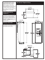
402® Series II Speaker Views
Top View
The electronic controller shall be the
Bose PANARAY system digital
controller
Safety and Regulatory
Compliance
All versions of the Bose 402 Series II
loudspeakers comply with ANSI/EIA
636, Recommended Loudspeaker
Safety Practices and EMC Directive
89/336/EEC and Article 10 (1) of the
Directive in compliance with
EN50081-1, EN50082-1, as signified
by the CE mark.
Rear View
Side View
Warranty Information
All versions of the Bose 402 Series II
loudspeaker are covered by a 5-year,
transferable limited warranty.
Bottom View
©2003 Bose Corporation, The Mountain
Framingham, MA 01701-9168
Subject to change without notice.
PN269262 AM Rev.00 PC031392 JN30026
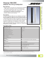
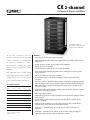
Panaray® MA12EX
Modular Line Array Loudspeaker
TECHNICAL DATA SHEET
Key Features
• Designed to deliver full-range music and high speech intelligibility
in both indoor and outdoor acoustically demanding spaces
• Full-range music performance from 75 Hz to 13 kHz (-3 dB)
without the need for additional bass augmentation
• Articulated Array® loudspeaker technology delivers wide
horizontal dispersion for broad 160° coverage*
• Available in black or white, paintable
Description
The Panaray® MA12EX modular line array loudspeaker is designed
for indoor and outdoor applications where full-range music and
speech intelligibility are required. The Panaray MA12EX loudspeaker
is engineered to provide full-range music performance from 75 Hz
to 13 kHz (-3 dB) without the need for additional bass augmentation.
The MA12EX loudspeaker can be mounted in single or multiple
loudspeaker configurations. This loudspeaker is well-suited for
indoor and outdoor applications such as houses of worship, multipurpose spaces, recreation, restaurants, auditoriums, transportation
hubs, gymnasiums, atriums and malls.
Descriptive Data
System Performance (Single Module)
Frequency Response (-3 dB) 1
75 Hz - 13 kHz
Frequency Range (-10 dB) 1
58 Hz - 16 kHz
Calculated Maximum SPL @ 1m2
Input Power Rating (continuous/peak)
Axial Sensitivity (SPL/1W @ 1m)
109 dB
3
150W/600W 6
4
87 dB
Nominal Horizontal Coverage (-6 dB)
160°
Nominal Vertical Coverage (-6 dB) 5
20°
Nominal Impedance (transformer bypass)
8?
Minimum Impedance
7.1?
Crossover Frequency
N/A
Recommended High-Pass Filter
65 Hz
Transducers
Driver Complement
Twelve 2.25" (57mm) high-excursion, weather-resistant drivers
Physical
Powder-coated aluminum
Enclosure Material
Grille
Powder-coated aluminum
Environmental Specification
Indoor and outdoor use per IEC 529 IPX5 specifications
Connectors
Two parallel-wired Neutrik Speakon® NL4 connectors
Two two-conductor barrier strips
Suspension Attachment
6 x M6 threaded inserts
Dimensions (H x W x D)
38.8" x 4.1" x 5.5"
(986mm x 104mm x 140mm)
Net Weight
20.8lbs
Shipping Weight
22.9lbs
Notes:
*Articulated Array loudspeaker technology produces wide, uniform sound coverage by angling every other driver within the enclosure to create 160 degrees of
horizontal coverage and consistent tonal balance.
1– 4
5
See “How our Loudspeakers are Measured” on page 6. Vertical coverage varies by number of modules vertically arrayed and distance from line-source boundary.
Use Modeler® software for the best prediction.
6
150W for full-range music and speech applications. Speech-only applications (155 Hz to 12 kHz), power handling (continuous) at 300W/1200W.
Bose Professional Systems Division
1
OF 8
pro.Bose.com
Panaray MA12EX
®
Modular Line Array Loudspeaker
TECHNICAL DATA SHEET
Recommended Equalization
PEQ2
PEQ3
PEQ4
PEQ5
PEQ6
MA12EX Stacked Wall
PEQ1
MA12EX Stacked Free
Freq. (Hz)
Slope (dB/octave)
Type
Type
Freq. (Hz)
Bandwidth
Level (dB)
Type
Freq. (Hz)
Bandwidth
Level (dB)
Type
Freq. (Hz)
Bandwidth
Level (dB)
Type
Freq. (Hz)
Bandwidth
Level (dB)
Type
Freq. (Hz)
Bandwidth
Level (dB)
Type
Freq. (Hz)
Bandwidth
Level (dB)
HPF
MA12EX Wall
Application
MA12EX Free Air
MA12EX Processor Settings
63.1
24
Butterworth
PEQ
100
1.6
6
PEQ
251.2
1.25
-6
PEQ
891. 3
2
-4
PEQ
2k
1
-4 . 5
PEQ
7.94k
1.25
-10
PEQ
12.6k
0.8
5.5
63.1
24
Butterworth
PEQ
89.13
1.25
3
PEQ
251.2
1
-4
PEQ
794. 3
0.63
-3
PEQ
2k
1
-3.5
PEQ
7.94k
1
-8
PEQ
12.6k
0.63
7
70
24
Butterworth
PEQ
100
1.6
6
PEQ
251.2
1
-4.5
PEQ
707. 9
2
-5
PEQ
1. 78k
0.8
-3
PEQ
7.08k
0.63
-8
PEQ
12.6k
1.6
6
63.1
24
Butterworth
PEQ
199.5
1.25
-4
PEQ
631
0.8
-3
PEQ
794. 3
1.25
-5.5
PEQ
2k
1
-5
PEQ
7.08k
1
-8
PEQ
12.6k
0.63
7
Note: The above settings were developed for ControlSpace® Systems. Other devices will vary.
Mechanical Diagrams
Wiring Diagram
M6 x 15mm
6X
NL4
+
–
Refer to your instruction manual for proper
installation and operation procedures.
Panaray® MA12EX Modular
Line Array Loudspeaker
Must be used with a BOSE Panaray
System Controller or Amplifier Card
5.5"
14.0 cm
2
OF 8
BOSE CORPORATION, THE MOUNTAIN, FRAMINGHAM, MA 01701-9168
COVERED BY U.S. PATENT D480069
MADE IN CHINA, ENGINEERED IN THE USA
4.1"
10.4 cm
6.0"
15.2 cm
10.1"
25.7 cm
12.8"
32.5 cm
38.8"
98.5 cm
11.5"
29.3 cm
NL4 wiring
NL4
pro.Bose.com
loudspeaker
loudspeaker
thru
thru
Panaray MA12EX
®
Modular Line Array Loudspeaker
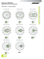
125 Hz Octave Band
250 Hz Octave Band
90
120
60
120
150
30
-30 -24 -18 -12 -6
0
30
-30 -24 -18 -12 -6
0
210
330
-30 -24 -18 -12 -6
210
300
330
240
300
270
200 Hz
400 Hz
125 Hz
250 Hz
500 Hz
160 Hz
315 Hz
630 Hz
2000 Hz Octave Band
4000 Hz Octave Band
90
120
60
120
150
30
-30 -24 -18 -12 -6
0
120
30
-30 -24 -18 -12 -6
0
210
90
60
150
6
180
330
0
300
330
240
30
-30 -24 -18 -12 -6
0
210
60
150
6
180
270
300
0
6
180
0
210
330
240
270
300
270
800 Hz
1600 Hz
3150 Hz
1000 Hz
2000 Hz
4000 Hz
1250 Hz
2500 Hz
5000 Hz
8000 Hz Octave Band
6
0
100 Hz
90
0
180
270
1000 Hz Octave Band
16000 Hz Octave Band
90
90
60
120
150
30
-30 -24 -18 -12 -6
180
0
210
300
30
6
-30 -24 -18 -12 -6
330
270
60
150
0
240
30
6
330
240
60
150
0
210
300
120
0
180
270
240
90
120
60
150
6
180
240
500 Hz Octave Band
90
TECHNICAL DATA SHEET
Polar Plots 1⁄ 3 Octave Horizontal
180
0
6
0
210
330
240
300
270
6300 Hz
12500 Hz
8000 Hz
10000 Hz
3
OF 8
pro.Bose.com
Panaray MA12EX
®
Modular Line Array Loudspeaker
125 Hz Octave Band
250 Hz Octave Band
90
120
60
120
150
30
-30 -24 -18 -12 -6
0
30
-30 -24 -18 -12 -6
0
210
330
240
300
270
400 Hz
500 Hz
160 Hz
315 Hz
630 Hz
2000 Hz Octave Band
4000 Hz Octave Band
90
120
30
-30 -24 -18 -12 -6
0
120
30
-30 -24 -18 -12 -6
0
210
90
60
150
6
180
330
0
300
330
240
30
-30 -24 -18 -12 -6
0
210
60
150
6
180
270
300
180
210
300
270
1600 Hz
3150 Hz
1000 Hz
2000 Hz
4000 Hz
1250 Hz
2500 Hz
5000 Hz
16000 Hz Octave Band
90
60
120
150
30
-30 -24 -18 -12 -6
180
0
150
-30 -24 -18 -12 -6
330
300
270
30
6
0
210
60
180
8000 Hz
10000 Hz
6
0
210
330
240
300
270
6300 Hz
0
12500 Hz
6
330
800 Hz
90
0
0
240
270
8000 Hz Octave Band
pro.Bose.com
300
250 Hz
60
6
330
200 Hz
150
OF 8
210
125 Hz
120
0
0
100 Hz
90
4
-30 -24 -18 -12 -6
180
270
1000 Hz Octave Band
240
30
6
330
240
60
150
0
210
300
120
0
180
270
240
90
120
60
150
6
180
240
500 Hz Octave Band
90
TECHNICAL DATA SHEET
Polar Plots 1⁄ 3 Octave Vertical
Panaray MA12EX
®
Modular Line Array Loudspeaker
TECHNICAL DATA SHEET
Beamwidth
Beamwidth
Angle (degrees)
360
100
10
Horizontal
Vertical
20
100
1000
10000
20000
Frequency (Hz)
Directivity
and Q
Directivity Index Index
and Q
30
1000
Directivity Index (dB)
25
20
100
Q
15
10
10
5
0
1
20
100
1000
10000
20000
Frequency (Hz)
1
Average
Frequency
Response
Average Frequency
Response and
Impedance and Impedance
30
100
Level (dB−SPL)
10
0
10
−10
−20
Impedance (Ohms)
20
Average Frequency Response
Impedance
−30
20
100
1000
10000
1
20000
Frequency (Hz)
1
See “How our Loudspeakers are Measured” on page 6.
5
OF 8
pro.Bose.com
Panaray MA12EX
®
Modular Line Array Loudspeaker
The loudspeaker shall be a multiple driver,
full-range system with matched active
equalization as follows:
The transducer complement shall consist of
twelve 2.25" (57mm) high-excursion, weatherresistant drivers mounted in an Articulated Array®
loudspeaker design. Each driver shall have a rated
impedance of 5g and wired in series/parallel,
resulting in a composite nominal impedance
of 8g.
The nominal horizontal beamwidth of the
loudspeaker shall be 160°, and the vertical
coverage is a band of constant height. The
power handling capacity of the loudspeaker
shall be 150W continuous pink noise, band –
limited from 75 Hz to 13 kHz (-3 dB).
How our Loudspeakers
are Measured
1. Frequency Response and Range
Data is the average response in the typical
coverage area with the recommended
equalization applied.
2. Calculated Max SPL
Calculated based on input sensitivity with
recommended equalization applied and
maximum input power rating exclusive of
power compression.
3. Input Power Rating
Pink noise with a 6 dB crest factor is bandpass
limited to the operating range of the
loudspeaker and applied for 100 hours.
4. Axial Sensitivity
The loudspeaker shall be provided with a ducted
vent system, tuned at 75 Hz. The input connector
of the loudspeaker module shall consist of two
parallel-wired Speakon® NL4 receptacles and
two two-conductor barrier strips.
Full-bandwidth pink noise with recommended
equalization amplified to a level of 1 watt and
applied to the loudspeaker in an anechoic
environment.
The enclosure of the MA12EX speaker module
shall be aluminum. Its outer dimensions shall
be 38.8" H x 4.1" W x 5.5" D (986mm x 104mm
x 140mm). Its weight shall be 20.8lbs.
More Information
The loudspeaker shall be the Bose® Panaray®
MA12EX modular line array loudspeaker.
Safety and Regulatory Compliance
The MA12EX loudspeaker complies with
ANSI/EIA-636 Recommended Loudspeaker
Safety Practices.
Rigging
MA12EX loudspeakers can be mounted as a
single element or stacked in multiples to achieve
line array performance. Bose MA12EX loudspeaker
mounting brackets are available and tested for
use with single-, double- and triple-stack MA12EX
loudspeaker installations. For installations of four
or more MA12EX loudspeakers, obtain your
mounting system from a reputable manufacturer.
Select a system design that works for your loudspeaker of choice and its intended use. Always
have a licensed professional engineer review the
design and fabrication for structural integrity and
safety in the intended application.
6
OF 8
pro.Bose.com
Technical literature and other materials are
available at pro.Bose.com.
TECHNICAL DATA SHEET
Engineers’ and Architects’
Specifications
Panaray MA12EX
®
Modular Line Array Loudspeaker
TECHNICAL DATA SHEET
Product Codes
Loudspeaker
MA12EX Loudspeaker Black . . . . . . . . . . . . . . . . . . . . . . . . . . . . . . . . . . . . . . . . . . . . . PC 317302-0100
MA12EX Loudspeaker White . . . . . . . . . . . . . . . . . . . . . . . . . . . . . . . . . . . . . . . . . . . . PC 317302-0200
Accessories
CB-MA12EX Coupling Bracket Black . . . . . . . . . . . . . . . . . . . . . . . . . . . . . . . . . . . . . . PC 317088-0100
CB-MA12EX Coupling Bracket White . . . . . . . . . . . . . . . . . . . . . . . . . . . . . . . . . . . . . PC 317088-0200
CVT-MA12EX Transformer 70V/100V Black . . . . . . . . . . . . . . . . . . . . . . . . . . . . . . . . . PC 315338-0100
CVT-MA12EX Transformer 70V/100V White . . . . . . . . . . . . . . . . . . . . . . . . . . . . . . . . PC 315338-0200
WB-MA12/MA12EX Pitch Only Bracket Black . . . . . . . . . . . . . . . . . . . . . . . . . . . . . . . PC 318418-0100
WB-MA12/MA12EX Pitch Only Bracket White . . . . . . . . . . . . . . . . . . . . . . . . . . . . . . PC 318418-0200
WMB-MA12/MA12EX Bi-Pivot Bracket Black . . . . . . . . . . . . . . . . . . . . . . . . . . . . . . . PC 318338-0100
WMB-MA12/MA12EX Bi-Pivot Bracket White . . . . . . . . . . . . . . . . . . . . . . . . . . . . . . . PC 318338-0200
WMB2-MA12/MA12EX Pitch Lock Upper Bracket Black . . . . . . . . . . . . . . . . . . . . . . . PC 318337-0100
WMB2-MA12/MA12EX Pitch Lock Upper Bracket White . . . . . . . . . . . . . . . . . . . . . . PC 318337-0200
Replacement Parts
MA12EX Grille Black
. . . . . . . . . . . . . . . . . . . . . . . . . . . . . . . . . . . . . . . . . . . . . . . . . . PC 317423-010S
MA12EX Grille White . . . . . . . . . . . . . . . . . . . . . . . . . . . . . . . . . . . . . . . . . . . . . . . . . . PC 317423-020S
Bose Logo Black . . . . . . . . . . . . . . . . . . . . . . . . . . . . . . . . . . . . . . . . . . . . . . . . . . . . . . PC 317418-010S
Bose Logo White
. . . . . . . . . . . . . . . . . . . . . . . . . . . . . . . . . . . . . . . . . . . . . . . . . . . . . PC 317418-020S
2.25" (57mm) driver . . . . . . . . . . . . . . . . . . . . . . . . . . . . . . . . . . . . . . . . . . . . . . . . . . . PC 318828-000S
Endcap Black . . . . . . . . . . . . . . . . . . . . . . . . . . . . . . . . . . . . . . . . . . . . . . . . . . . . . . . . . PC 317414-010S
Endcap White . . . . . . . . . . . . . . . . . . . . . . . . . . . . . . . . . . . . . . . . . . . . . . . . . . . . . . . . PC 317414-020S
7
OF 8
pro.Bose.com
8
OF 8
pro.Bose.com
All information subject to change without notice.
©2009 Bose Corporation.
Bose, Panaray, Articulated Array, Modeler and ControlSpace are registered trademarks of Bose Corporation in the U.S. and other countries.
Other marks are the property of their owners. C_007400
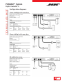
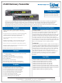
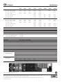
PANARAY® System
TECHNICAL DATA SHEET
Digital Controller II
Product Overview
The Bose® Panaray® system digital controller is a
universal EQ controller engineered to provide Bose
professional loudspeakers with active equalization.
The EQs for Bose professional loudspeakers can be
accessed by selecting the appropriate preset and
configuration. No programming is required.
Product Information
The Panaray system digital controller utilizes
digital signal processing (DSP) architecture to
provide active equalization and signal processing
for Bose professional loudspeakers. The controller
features a complete set of Bose active equalization
presets. Individual input sensitivity and output range,
as well as master output level, are adjustable via
the user interface buttons and easy-to-read 2 x 16
backlit LCD display on the front panel.
The Panaray system digital controller can be
configured for mono or stereo operation. A bass
mono sum feature is available for situations where
stereo mid/high loudspeakers are paired with a
single bass loudspeaker. The controller offers
configurations designed for bass array applications.
It also offers global limiting to protect against
unpredictable spikes in program material.
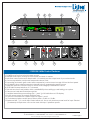
The Panaray system digital controller features
two analog, balanced, differential XLR inputs and
four analog, balanced, differential XLR outputs.
The unit also has a RS232 connector for future
software updates.
Key Features
• Two balanced differential XLR inputs and four
balanced differential XLR outputs
• Preset active equalization settings for all Bose
professional loudspeakers
• Bass mono sum option for using a single
low-frequency loudspeaker with stereo
mid/high loudspeakers
• Bass array presets for Panaray bass loudspeakers
• Special “lockout” feature prevents tampering to
maintain initial system settings
• Global limiter protect function option
• Easy-to-read 2 x 16 backlit LCD display
• Signal input and clipping LED indicators
• RS232 connector for software updates
Applications
The Panaray system digital controller is well-suited
for portable and installed professional sound systems.
PROFESSIONAL SYSTEMS
1
OF 4
pro.bose.com
PANARAY® System
TECHNICAL DATA SHEET
Digital Controller II
Product Specifications
Inputs:
2 analog, balanced, differential, XLR
Input impedance:
Differential 2.21kΩ @ 1 kHz
Maximum input level:
+18 dBu
Sensitivity range @ full scale:
Selectable, 0/+6/+12/+18 dBu
Outputs:
4 analog, balanced, differential, XLR
Output impedance:
Differential 200 Ω
Maximum output level (balanced):
+18 dBu
Output ranges (balanced):
Selectable, 0/+6/+12/+18 dBu
Audio indicators:
Signal (Present) – Green LED
Signal (Clip) – Red LED
Mains voltage:
100 to 240 VAC, 50 to 60 Hz (auto-select)
Power consumption:
15W
Environmental:
Operating temperature: 32° – 104°F (0° – 40°C)
Storage temperature: -4° – 122°F (-20° – 50°C)
Humidity: 95% relative humidity
Dimensions:
19"W x 8.27"D x 1.77"H
(483mm x 210mm x 45mm)
Weight:
Product: 5.9lb (2.7kg)
Shipping: 7.8lb (3.5kg)
Conversion:
44.1 kHz
Throughput delay:
1.52ms
Dynamic range:
103 dB (typical)
Mechanical diagram:
THD:
0.003% (typical)
Frequency response:
20 Hz to 20 kHz (+0/-1 dB)
7.87 [200.00] 7.87 [200.00]
8.27 [210.00] 8.27 [210.00]
Crosstalk:
100 dB (typical)
Communication port:
RS232 (for software updates only)
1.77 [45.00]
1.77 [45.00]
19.02 [483.00] 19.02 [483.00]
TOP TOP
VIEWVIEW
SIDESIDE
VIEWVIEW
Stereo
PANARAY
PANARAY
SYSTEM
SYSTEM
DIGITAL
DIGITAL
CONTROLLER
CONTROLLER
II
802III
2
OF 4
pro.bose.com
II
PANARAY® System
TECHNICAL DATA SHEET
Digital Controller II
Configuration diagrams:
Stereo mid/high with mono bass
Mono mid/high with mono bass
2X endfire bass array
3
OF 4
pro.bose.com
PANARAY® System
TECHNICAL DATA SHEET
Digital Controller II
Engineers’ and Architects’
Specifications
The controller shall use a digital signal processing
architecture running at a 44.1 kHz sample rate. The
frequency response shall be from 20 Hz to 20 kHz
(+0/-1 dB). The dynamic range shall be 103 dB (typical) 20 Hz to 20 kHz.
The controller shall include a single analog, balanced,
differential XLR input connector for each of the two
input channels. It shall have a single analog, balanced,
differential XLR output for each of its four outputs.
The maximum input level shall be +18 dBu. The
maximum output level shall be +18 dBu. The input
impedance shall be 2.21k ohms for balanced
operation. The output impedance shall be 200 ohms.
Limited Warranty
The Panaray system digital controller II is covered
by a one-year transferable limited warranty.
Product Codes
Panaray system digital controller II
120V – US
230V – EU
100V – Japan
230V – UK
240V – AU
PC
PC
PC
PC
PC
040500
040502
040501
040503
040504
The throughput delay time through the controller
shall be 1.52ms.
Crosstalk shall be <-100 dB (typical).
The THD shall be <0.003% (typical).
A 9-pin RS232 connector COM port shall be
used for software updates.
The power supply shall be auto switching from
100 to 240 VAC, 50 to 60 Hz. Power consumption
shall be < 15W.
The controller shall be the Bose® Panaray® system
digital controller II.
Safety and Regulatory Compliance
The Panaray system digital controller II complies
with CE requirements, is cUL Listed according
to UL60065 (7th edition) and CAN/CSA C22.2
No. 60065-03, CB approved according to IEC60065
(7th edition) including group and National differences,
GS approved according to EN600065 (7th edition)
and is PSE compliant. It also complies with FCC Part
15B Class A (2003), EN55103-1 (1997), EN55103-2
(1996), and CISPR13 (2003) requirements.
4
OF 4
pro.bose.com
All information subject to change without notice.
©2006 Bose Corporation.
Bose and Panaray are registered trademarks of Bose Corporation.
CCM-003838 PC041975
LR-400 Portable Display FM
Receiver
&RQÀJXUDWLRQ
LR-400-072
LR-400-216
LR-400-863
The LR-400 Portable Display FM Receiver is a lower cost digital
display receiver. It has exceptional audio quality as Listen’s
full-featured receivers and the same convenient recharging
options. The LR-400 can receive up to 17 wide band channels
along with 40 narrow bands (72 MHz), 19 wide band with 38
narrow band (216 MHz) and 17 wide band (863 MHz) channels.
The LR-400 has a digital display to monitor channel selection,
EDWWHU\OHYHODQGVLJQDOVWUHQJWK$Q/('RQWRSVLJQLÀHVLIWKH
XQLWLVRQÁDVKHVZKHQEDWWHULHVDUHORZRUORFNHGRQDFKDQQHO
if it blinks while pushing SEEK.
$UFKLWHFWXUDO6SHFLÀFDWLRQ
+LJKOLJKWV
•Superior Audio Quality – 80 dB (70 dB with 863 MHz)
signal-to-noise ratio, setting the industry’s sound quality
standard.
•A choice between 57 channels (17 channels with 863 MHz),
complete antenna and accessory options make Listen products
ideal for a wide range of applications.
•100 % Digital – Listen receivers are digitally-tuned so transmission
won’t drift; assurance that when you select a channel, it stays
on the channel.
•Uses standard alkaline or NiMH batteries.
•Built in SmartCharge™ won’t allow batteries to overcharge.
Charging circuitry is conveniently built into Listen’s receivers;
never worry about unplugging a transformer at a certain time.
•Transformer charging plug or for the ultimate in convenience
drop in charging contacts.
•Limited Lifetime Warranty with hassle-free support.
Requires
Requires a type of ear piece and (2) AA batteries.
LA-161 Single Ear Bud
LA-162 Stereo Ear Bud
LA-164 Ear Speaker
LA-165 Stereo Headphones
LA-166 Neck Loop
LA-170 Behind-the-Head Stereo Headphones
LA-361 High Capacity AA Alkaline Batteries (2)
LA-362 Rechargeable AA NiMH Batteries (2)
Used With
LT-800 Stationary FM Transmitter
LT-700 Portable FM Display Transmitter
LR-400-072/216
The FM receiver shall be capable of receiving on 57 wide and
narrow band channels. The receiver shall have a SNR of 80 dB or
greater. The receiver shall be capable of seeking channels. The
device shall have a squelch. The device shall have an audio
frequency response of 50 Hz to 15 KHz, ± 3 dB at 72 MHz and
50 - 10 kHz (±3dB) at 216 MHz. The device shall incorporate a
stereo headset jack that allows the user to plug in either a mono
or stereo headset and listen to audio normally. The device shall
incorporate an LCD display that indicates channel, battery level,
low battery, battery charging, RF signal strength and channel lock
status. The unit shall operate off of 2 AA batteries. The receiver shall
incorporate automatic battery charging circuitry for recharging
of NiMH batteries. The device shall have a switchable option for
the use of (2) alkaline or (2) NiMH batteries. The Listen LR-400-072 or
/5LVVSHFLÀHG
LR-400-863
The FM receiver shall be capable of receiving on 17 wide band
channels with a SNR of 70dB or greater. The device shall be able
to be locked on a single channel. The receiver shall be capable
of seeking channels. The device shall have an adjustable squelch.
The device shall have an audio frequency response of 50 Hz to 15
KHz, ±3 dB. The device will incorporate a stereo headset jack that
allows the user to plug in either a mono or stereo headset. The
device shall incorporate an LCD display that indicates channel,
battery level, low battery, battery charging, and RF signal strength.
The receiver shall be able to function in both DX and Local mode.
The unit shall operate off of 2 AA batteries. The receiver shall
incorporate automatic battery charging circuitry for recharging
of NiMH batteries. The device shall have a switchable option for
the use of (2) alkaline or (2) NiMH batteries.The Listen LR-400-863 is
VSHFLÀHG
Includes
LR-400 Portable Display FM Receiver
Owner’s manual (72 MHz & 216 MHz)
Quick Reference Card (863 MHz)
Limited Lifetime Warranty Program Card (863 MHz)
FM System Design Guide and Manual Card (863 MHz)
Listen Technologies Corporation • 14912 Heritagecrest Way • Bluffdale • Utah 84065-4818 U.S.A.
+1.801.233.8992 • +1.800.330.0891 North America • +1.801.233.8995 Fax
Listen Technologies Corporation All rights reserved 91707
LR-400 Page 1
1
2
3
4
12
10
5
9
11
6
8
7
9
Product Features LR-400-072/216
1. An earphone jack (3.5 mm) accepts either mono or stereo headsets. Receiver antenna is built into the
earphone cord, eliminating additional wires while maximizing receiver effectiveness.
2. Multifunction LED indicates power on, if batteries are low, if the unit is locked on a channel when SEEK is
pressed and charging status.
3. Easy on/off volume control.
4. Look&Listen™ LCD Display shows channel selection, channel lock and battery level.
6HHNVWRÀQGEHVWDYDLODEOHEURDGFDVW$OVRXVHGWRDGMXVWDEOHVTXHOFKLQVWHSVPXWHVDXGLRRQORVVRI5) signal.
6. Uses two AA batteries. Selectable to use either alkaline or Listen’s advanced NiMH Rechargeable
AA Batteries. SmartCharge™ incorporated into receiver makes sure each unit receives the most
EHQHÀFLDOFKDUJH
7. When enabled, SQ provides highest audio quality available in its product category. SQ can be disabled for
compatibility with other assistive listening equipment.
8. Digitally tuned with UP, DOWN, and SEEK buttons behind manually lockable door. Electronically lock on
channel by holding the SEEK button down 5 seconds to prevent tampering.
9. Manually lockable battery compartment door.
10. Charging plug port.
11. Contact points for Listen’s drop in charging cases.
12. Exclusive belt clip “loop” prevents unit from slipping off belt or strap.
Listen Technologies Corporation • 14912 Heritagecrest Way • Bluffdale • Utah 84065-4818 U.S.A.
+1.801.233.8992 • +1.800.330.0891 North America • +1.801.233.8995 Fax
Listen Technologies Corporation All rights reserved 91707
LR-400 Page 2
1 2
3
4
11
9
5
8
7
10
6
8
Product Features LR-400-863
1. An earphone jack (3.5 mm) accepts either mono or stereo headsets. Receiver antenna is built into the
earphone cord, eliminating additional wires while maximizing receiver effectiveness.
2. Multifunction LED indicates power on, if batteries are low, if the unit is locked on a channel when SEEK is
pressed and charging status.
3. Easy on/off volume control.
4. Look&Listen™ LCD Display shows channel selection, channel lock and battery level.
6HHNVWRÀQGEHVWDYDLODEOHEURDGFDVW$OVRXVHGWRDGMXVWVTXHOFKLQVWHSVZKLFKPXWHVDXGLRRQORVVRI5)
signal.
6. Uses two AA batteries. Selectable to use either alkaline or Listen’s advanced NiMH Rechargeable
AA Batteries. SmartCharge™ incorporated into receiver makes sure each unit receives the most
EHQHÀFLDOFKDUJH
7. Digitally tuned with UP, DOWN, and SEEK buttons behind manually lockable door. Electronically lock on
channel by holding the SEEK button down 5 seconds to prevent tampering.
8. Manually lockable battery compartment door. 10. Contact points for Listen’s drop in charging cases.
9. Charging plug port.
10. Contact points for Listen’s drop in charging cases.
11. Exclusive belt clip “loop” prevents unit from slipping off belt or strap.
Listen Technologies Corporation • 14912 Heritagecrest Way • Bluffdale • Utah 84065-4818 U.S.A.
+1.801.233.8992 • +1.800.330.0891 North America • +1.801.233.8995 Fax
Listen Technologies Corporation All rights reserved 91707
LR-400 Page 3
Accessories
Headphones
LA-170
LA-161 Single Ear Bud
LA-162 Stereo Ear Bud
LA-164 Ear Speaker
LA-165 Stereo Headphones
LA-166 Neck Loop
LA-170 Behind-the-Head Stereo Headphones
3RZHU&KDUJLQJ6XSSOLHV
LA-202 Power/Charging Supply for FM Portable Products
LA-208-01 7.5 VDC Power/Charging Supply for FM Portable Products (North America)
LA-208-02 7.5 VDC Power/Charging Supply for FM Portable Products (Asia, UK)
LA-208-03 7.5 VDC Power/Charging Supply for FM Portable Products (Euro)
LA-202
Cables
LA-265 Consumer Camcorder Cable
LA-266 Professional Camcorder Cable
/$6DFULÀFLDO&DEOH
LA-266
&KDUJLQJ&DUU\LQJ&DVHV
LA-321
LA-311-01 16-Unit Portable FM Product Charging/Carrying Case (North America)
LA-311-02 16-Unit Portable FM Product Charging/Carrying Case (Asia, UK)
LA-311-03 16-Unit Portable FM Product Charging/Carrying Case (Euro)
LA-317-01 4-Unit Portable FM Product Charging/Carrying Case (North America)
LA-317-02 4-Unit Portable FM Product Charging/Carrying Case (Asia, UK)
LA-317-03 4-Unit Portable FM Product Charging/Carrying Case (Euro)
LA-321-01 8-Unit Portable FM Product Charging/Carrying Case (North America)
LA-321-02 8-Unit Portable FM Product Charging/Carrying Case (Asia, UK)
LA-321-03 8-Unit Portable FM Product Charging/Carrying Case (Euro)
&KDUJLQJ&DUU\LQJ&DVHVZLWK5HPRYDEOH/LG
LA-324
LA-323-01 4-Unit Portable FM Product Charging/Carrying Case w/Removable Lid (North America)
LA-323-02 4-Unit Portable FM Product Charging/Carrying Case w/Removable Lid (Asia, UK)
LA-323-03 4-Unit Portable FM Product Charging/Carrying Case w/Removable Lid (Euro)
LA-324-01 8-Unit Portable FM Product Charging/Carrying Case w/Removable Lid (North America)
LA-324-02 8-Unit Portable FM Product Charging/Carrying Case w/Removable Lid (Asia, UK)
LA-324-03 8-Unit Portable FM Product Charging/Carrying Case w/Removable Lid (Euro)
LA-325-01 16-Unit Portable FM Product Charging/Carrying Case w/Removable Lid (North America)
LA-325-02 16-Unit Portable FM Product Charging/Carrying Case w/Removable Lid (Asia, UK)
LA-325-03 16-Unit Portable FM Product Charging/Carrying Case w/Removable Lid (Euro)
Miscellaneous
LA-362
LA-306 Soft Case (72 MHz & 216 MHz only)
LA-319 Protective Pouch for Portable FM Products
/$&RQÀJXUDEOH&DUU\LQJ&DVH
LA-330 Portable Unit Lanyard
LA-361 High Capacity AA Alkaline Batteries (2)
LA-362 Rechargeable AA NiMH Batteries (2)
Listen Technologies Corporation • 14912 Heritagecrest Way • Bluffdale • Utah 84065-4818 U.S.A.
+1.801.233.8992 • +1.800.330.0891 North America • +1.801.233.8995 Fax
Listen Technologies Corporation All rights reserved 91707
LR-400 Page 4
LR-400-072
6SHFLÀFDWLRQV
RF Frequency Range
72.025 - 75.950 MHz
216.0125 - 216.9875 MHz
Number of Channels
17 wide band, 40 narrow band
19 wide band, 38 narrow band
Sensitivity
RF
LR-400-216
.6 uV typical, 1 uV maximum for 12dB sinad
Frequency Accuracy
VWDELOLW\ÝWRÝ)ÝÝ&
Antenna
Uses earphone cable
Squelch
Programmable in 20 steps, automatic on loss of RF signal
Compliance
FCC Part 15, Industry Canada
FCC Part 90, Industry Canada
$OOV\VWHPVSHFLÀFDWLRQVDUHZLUHOHVVHQGWRHQG
System Frequency Response
System Signal to Noise Ratio
Audio
System Distortion
<2% total harmonic distortion (THD) at 80% deviation
User Controls
Volume, channel UP/DOWN, SEEK
Set up Controls
(battery compartment)
Alkaline/NiMH batteries, SQ enable/disable
Programming
Channel lock, squelch
Red, illuminated when unit is on. Flashes when batteries are low, or to indicate charging.
Flashes when locked and SEEK is pushed.
LED
Indicators
Display
Channel Designation, lock status, signal strength indication
Battery Type
Two AA batteries, alkaline or NiMH
Battery Life (Listen Batteries)
Battery Charging (NiMH only)
Power
Power Supply
Power Supply Connector
Power Supply Compliance
Fully automatic, 13 hours
I/P 120VAC; O/P 7.5VDC 250 mA; Drop in contact points for use with charging cases.
Power supply not included (LA-202)
2.3 mm OD by 0.7 mm ID, barrel type connector, 7.5 VDC, center positive <250 mA.
Drop in contact points for use with Listen charging cases.
RoHS, WEEE, UL, PSE, CE, CUL, TUV, CB compliant
5.0 x 3.0 x 1.0 in. (13 x 7.6 x 2.5 cm)
Color
Dark Grey with white silk screening
Unit Weight with batteries
Shipping Weight
Door
Temperature - Operation
Environmental
30 hours alkaline (LA-361), 15 hours NiMH rechargeable (LA-362)
Dimensions H x W x D
Unit Weight
Physical
50Hz - 10kHz (+/-3db) 216 MHz
SQ enabled: 80dB; SQ disabled 60dB
3.5 mm connectors, unbalanced, 0dBu nominal output level, 16 mW maximum,
impedance 32 Ohms
Output
Controls
50Hz - 15kHz (+/-3db) 72 Mhz
Temperature - Storage
Humidity
3.9 oz. (111 g)
5.8 oz. (164.4 g)
1.0 lb. (0.45 kg)
Manually lockable. SEEK behind the door.
ÝWRÝ)ÝWRÝ&
ÝWRÝ)ÝWRÝ&
0 to 95% relative humidity, non-condensing
6SHFLÀFDWLRQVDUHVXEMHFWWRFKDQJHZLWKRXWQRWLÀFDWLRQ
Listen Technologies Corporation • 14912 Heritagecrest Way • Bluffdale • Utah 84065-4818 U.S.A.
+1.801.233.8992 • +1.800.330.0891 North America • +1.801.233.8995 Fax
Listen Technologies Corporation All rights reserved 91707
LR-400 Page 5
LR-400-863
6SHFLÀFDWLRQV
RF
RF Frequency Range
863.050 - 864.950 MHz
Number of Channels
17 Wideband
Sensitivity
.6uV typical, 1 uV maximum for 12 dB sinad
Frequency Accuracy
VWDELOLW\WRÝÝ&
Antenna
Integrated External Antenna
Squelch
Programmable in 20 step, automatic on loss of RF signal
Compliance
CE, ETSI, RoHS
$OOV\VWHPVSHFLÀFDWLRQVDUHZLUHOHVVHQGWRHQG
System Frequency Response
Audio
Controls
Indicators
Power
Physical
Environmental
50Hz - 15kHz (+/-3db)
System Signal to Noise Ratio
70db (A-Weighted)
System Distortion
<2% total harmonic distortion (THD) at 80% deviation
Output
3.5 mm connector, unbalanced, 0dBu nominal output level, 16 mW
maximum, impedance 32 Ohms
User Controls
Channel up/down, SEEK, volume
Set up Controls
(battery compartment)
NiMH/Alkaline battery switch
Programming
Channel Lock, DX/Local, squelch
LED
Red, illuminated when unit is on. Flashes when batteries are low, or
charging. Flashes when locked and SEEK is pushed.
LCD Display
Channel Designation, lock status, signal strength indication, battery life
Battery Type
Type: 2 AA batteries, Alkaline or NiMH
Battery Life (Listen Batteries)
20 hours alkaline (LA-361), 10 hours NiMH rechargeable (LA-362)
Battery Charging (NiMH only)
Fully automatic, 13 hours maximum
Power Supply (LA-208)
7.5VDC, center positive 300mA. Drop in contact points for use with
charging cases. Power supply not included (LA-208).
Power Supply Connector
2.3 mm OD by .7 mm ID, barrel type
Power Supply Compliance
RoHS, WEEE, UL, PSE, CE, CUL, TUV, CB compliant
Dimensions (H x W x D)
5.0 x 3.0 x 1.0 in (13.0 x 7.6 x 2.5 cm)
Color
Dark Grey with white silk screening
Unit Weight
3.9 oz. (111 g)
Unit Weight with batteries
5.8 oz.. (164 g)
Shipping Weight
1.0 lbs. (0.45 kg)
Door
Manually lockable. Up, down, and power buttons through door. Other
controls behind door (see controls)
Temperature - Operation
14ÝÝ)-10Ý - 40Ý&
Temperature - Storage
-4ÝÝ)-20Ý - 50Ý&
Humidity
0 to 95% Relative Humidity, non condensing
6SHFLÀFDWLRQVDUHVXEMHFWWRFKDQJHZLWKRXWQRWLÀFDWLRQ
Listen Technologies Corporation • 14912 Heritagecrest Way • Bluffdale • Utah 84065-4818 U.S.A.
+1.801.233.8992 • +1.800.330.0891 North America • +1.801.233.8995 Fax
Listen Technologies Corporation All rights reserved 91707
LR-400 Page 6
Frequently Asked Questions
Q What is the difference between the LR-400 and the LR-500?
LR-500 gives the user an opportunity to lockout unused channels and has the controls on the outside
A The
of the front door.
Q Can the LR-400 be used with multiple transmitters?
The LR-400 can be used with multiple transmitters, but unlike the LR-500, it cannot be programmed to
A Yes.
lock out channels.
Q How many receivers can I have in a system?
A As many as you need, the number is endless
Q What is the function of SQ?
To reduce noise of our systems, Listen now offers a noise reduction technology called ListenSQ™
A (on
72 MHz and 216 MHz only). Both the transmitter and receiver must have SQ on to achieve the desired
results. If you are planning to use this product with older Listen systems or equipment not manufactured by
Listen, you should disable SQ.
Q What is the warranty of Listen receivers?
lifetime warranty. The following cases will void the warranty:
A Limited
• Misuse, dropping, or any other noticeable cosmetic damage
• Charging alkaline batteries instead of NiMH
• Overheating the charging process by closing the lid on the charging case.
Q How long do the batteries last on the LR-400 receiver?
batteries last 30 hours. NiMH rechargeable batteries last 15 hours (72 MHz and 216 MHz). With 863 MHz,
A Alkaline
Alkaline batteries last 20 hours and NiMH rechargeable batteries last 10 hours.
Listen Technologies Corporation • 14912 Heritagecrest Way • Bluffdale • Utah 84065-4818 U.S.A.
+1.801.233.8992 • +1.800.330.0891 North America • +1.801.233.8995 Fax
Listen Technologies Corporation All rights reserved 91707
LR-400 Page 7
LT-800 Stationary Transmitter
&RQÀJXUDWLRQ
Stationary FM Transmitter (72 MHz)
Stationary FM Transmitter (216 MHz)
Stationary FM Transmitter (863 MHz)
Thanks to its outstanding audio quality, the Listen LT-800 Stationary Transmitter can be used in a variety of applications.
The LT-800 is connected to your main audio system, broadcasting a high quality audio signal to belt pack receivers,
stationary receivers, or wireless speaker / receivers. The end result – your audience can hear and understand the
presentation better because of improved speaker placement or because they have their own belt pack and headset.
The signature Look & Listen™ LCD shows channel, lock, programming and RF power.
Highlights
•Superior Audio Quality – 80 dB (70 dB with 863 MHz)
signal-to-noise ratio, setting the industry’s sound quality
standard.
•A choice between 57 channels (17 channels with 863 MHz),
complete antenna and accessory options make Listen
products ideal for a wide range of applications.
•Long transmission range ensures coverage for the
entire venue.
•Designed for installation – Rack mountable with remote
antennas make installation easy and service reliable.
•Use the test tone or monitor jack to verify audio is present.
•Advanced audio processing (can be deactivated) ensures
audio levels are consistent to users.
•Limited Lifetime Warranty with hassle-free support.
,QFOXGHV
LT-800 Stationary Transmitter
LA-201 Replacement Power Supply for LT-800/LR-100/LR-600
(72 & 216 MHz)
LT-800 manual (72 & 216 MHz)
LA-129 Right Angle Articulating Antenna (863 MHz)
LA-207 12 Volt DC Universal Power Supply (863 MHz)
Line Cord (863 MHz)
Quick Reference Card (863 MHz)
Limited Lifetime Warranty Program Card (863 MHz)
FM System Design Guide and Manual Card (863 MHz)
Requires:
LA-101 Helical Top Mounted Antenna (72MHz)
LA-102 Telescoping Top Mounted Antenna (216MHz)
LA-106 Telescoping Top Mounted Antenna (72 MHz)
LA-107 Ground Plane Remote Antenna (216 MHz)
LA-116 Coaxial Dipole Remote Antenna (72MHz)
LA-117 Coaxial Dipole Remote Antenna (216 MHz)
LA-122 Universal Antenna Kit (72 and 216 MHz)
LA-123 90° Helical Antenna (72 MHz)
LA-124 90° Degree Helical Antenna (216 MHz)
LA-129 90°Articulating Antenna (863 MHz)
$UFKLWHFWXUDO6SHFLÀFDWLRQ
LT-800-072/216 MHz
The stationary FM transmitter shall be capable of broadcasting on
57 channels. The transmitter shall have a SNR of 80 dB or greater.
The output power shall be adjustable to quarter, half or full.
Channel tuning shall be capable of being locked. The device shall
broadcast on both wide and narrow band channels. The device
shall have an audio frequency response of 50 Hz to 15k Hz, ± 3 dB
at 72 MHz, or of 50 Hz to 10k Hz, ± 3 dB at 216 MHz. It shall have
two mixing audio inputs. The device shall have the following audio
FRQWUROVLQSXWOHYHOPL[OHYHODQGDQDGMXVWDEOHORZSDVVÀOWHU7KH
device shall have an audio processor that is capable of automatic
JDLQFRQWURODQGOLPLWLQJ7KH/LVWHQ/7LVVSHFLÀHG
LT-800-863 MHz
The Stationary FM Transmitter shall be capable of broadcasting on
17 channels. Channel tuning shall be capable of being locked. The
transmitter shall have a SNR of 70 db or greater. The output power
shall be adjustable to quarter, half or full. The device shall have an
audio frequency response of 50 Hz to 15 kHz, +/-3db. It shall have
2 mixing audio inputs and a mixed signal output. The device shall
have the following audio controls: Input Levels, Mix Level,
DGMXVWDEOHORZSDVVÀOWHUFRQWRXUKHDGSKRQHRXWSXWPRQLWRU
The device shall have an audio processor that is capable of
automatic gain control and limiting. The Listen LT-800-863 is
VSHFLÀHG
8VHG:LWK
/56WDWLRQDU\)05HFHLYHU3RZHU$PSOLÀHU0+]
/56WDWLRQDU\)05HFHLYHU3RZHU$PSOLÀHU0+]
LR-300-072 Portable Digital FM Receiver (72 MHz)
LR-400-072 Portable Display FM Receiver (72 MHz)
LR-400-216 Portable Display FM Receiver (216 MHz)
LR-400-863 Portable Display FM Receiver (863 MHz)
LR-500-072 Portable Programmable Display FM Receiver (72 MHz)
LR-500-216 Portable Programmable Display FM Receiver (216 MHz)
LR-500-863 Portable Programmable Display FM Receiver (863 MHz)
LR-600-072 Wireless FM Receiver/Speaker (72 MHz)
LR-600-216 Wireless FM Receiver/Speaker (216 MHz)
Listen Technologies Corporation • 14912 Heritagecrest Way • Bluffdale • Utah 84065-4818 U.S.A.
+1.801.233.8992 • +1.800.330.0891 North America • +1.801.233.8995 Fax
LT-800 Page 1
Listen Technologies Corporation All rights reserved 91407
3
2
1
10
11
12
4
5 6
7
8
9
13
14
15
16
/70+]3URGXFW)HDWXUHV
1. POWER on/off on front of unit for easy access.
2. Multiple audio inputs, with input level control and dual VU meters.
3. Mix Level control sets level of mixed audio. VU meter shows the output level of your mixed audio.
4. Contour equalization cuts/boosts frequencies above 5 kHz.
5. Processing (automatic gain control and compression) can be turned on and off from the front panel.
6. SQ (Super Quiet Companding Technology) can be turned on and off from the front panel.
7. LCD display shows channel selected, channel lockout, programming and RF power.
8. Earphone jack and volume control to check audio integrity of transmission source.
9. UP/DOWN channel selection of 57 channels. User can easily change between Basic and Expanded modes.
7KHWHVWWRQHOHYHOLVDGMXVWDEOHZKLFKDGGVÁH[LELOLW\ZKHQVHWWLQJXSDQGWHVWLQJ\RXUV\VWHP
11. Top mount, rear mount, and remote antenna options.
12. Multiple transmitter power settings (full, ½ and ¼) with indication on LCD display.
13. In-line power supply (included) attaches here.
14. 2 phono connectors for a mixed output of Inputs 1 and 2.
15. 2 unbalanced phono audio inputs. Select either +10 dBu or -10 dBu.
16. Balanced XLR / ¼ inch audio input. Select either mic, line or mic phantom power level for input. Electret
(Condenser) microphones can now be used with Input 1 phantom power.
Listen Technologies Corporation • 14912 Heritagecrest Way • Bluffdale • Utah 84065-4818 U.S.A.
+1.801.233.8992 • +1.800.330.0891 North America • +1.801.233.8995 Fax
LT-800 Page 2
Listen Technologies Corporation All rights reserved 91407
3
2
1
9
10
11
4
5
6
7
8
12
13
14
15
/70+]3URGXFW)HDWXUHV
1. POWER on/off on front of unit for easy access.
2. Multiple audio inputs, with input level control and dual VU meters.
3. Mix Level control sets level of mixed audio. VU meter shows the output level of your mixed audio.
4. Contour equalization cuts/boosts frequencies above 5 kHz.
5. Processing (automatic gain control and compression) can be turned on and off from the front panel.
6. LCD display shows channel selected, channel lockout, programming and RF power.
7. Earphone jack and volume control to check audio integrity of transmission source.
8. UP/DOWN channel selection of 17 channels.
7KHWHVWWRQHOHYHOLVDGMXVWDEOHZKLFKDGGVÁH[LELOLW\ZKHQVHWWLQJXSDQGWHVWLQJ\RXUV\VWHP
10. Rear mount and remote antenna options.
11. Multiple transmitter power settings (full, ½ and ¼) with indication on LCD display.
12. In-line power supply (included) attaches here.
13. 2 phono connectors for a mixed output of Inputs 1 and 2.
14. 2 unbalanced phono audio inputs. Select either +10 dBu or -10 dBu.
15. Balanced XLR / ¼ in. audio input. Select either mic, line or mic phantom power level for input. Electret
(Condenser) microphones can now be used with Input 1 phantom power.
Listen Technologies Corporation • 14912 Heritagecrest Way • Bluffdale • Utah 84065-4818 U.S.A.
+1.801.233.8992 • +1.800.330.0891 North America • +1.801.233.8995 Fax
LT-800 Page 3
Listen Technologies Corporation All rights reserved 91407
v
$FFHVVRULHV
$QWHQQDV
LA-124
LA-101 Helical Top Mounted Antenna (72MHz)
LA-102 Telescoping Top Mounted Antenna (216MHz)
LA-106 Telescoping Top Mounted Antenna (72 MHz)
LA-107 Ground Plane Remote Antenna (216 MHz)
LA-116 Coaxial Dipole Remote Antenna (72MHz)
LA-117 Coaxial Dipole Remote Antenna (216 MHz)
LA-122 Universal Antenna Kit (72 and 216 MHz)
LA-123 90Ý Helical Antenna (72 MHz)
LA-124 90Ý Helical Antenna (216 MHz)
LA-125 Antenna Kit for Rack Mount (72 MHz)
LA-126 Antenna Kit for Rack Mount (216 MHz)
LA-129 Right Angle Articulating Antenna (863 MHz)
LA-130 Remote Antenna Kit (863 MHz)
LA-131 Antenna Kit for Rack Mount (863 MHz)
3RZHU6XSSO\
LA-201 Replacement Power Supply for LT-800/LR-100/LR-600
LA-203 Replacement Power Supply for LA-317/LA-323
LA-207-01 12 VDC Replacement Power Supply for LT-800 (North America)
LA-207-02 12 VDC Replacement Power Supply for LT-800 (Asia, UK)
LA-207-03 12 VDC Replacement Power Supply for LT-800 (Euro)
LA-207
&DEOHV&RQQHFWRUV
LA-127
LA-112 RG-58 50 Ohm Coaxial Cable (Per ft.)
LA-113 RG-8 50 Ohm Low-Loss Coaxial Cable (Per ft.)
LA-115 RG-58 BNC Coupler
LA-121 BNC to Reverse BNC Adaptor (72MHz)
LA-127 RG-58 BNC Connector
LA-128 RG-8 BNC Connector
LA-390 RG-8/50 Ohm Preassembled Coaxial Cable (Per ft.)
LA-391 RG-58/50 Ohm Preassembled Coaxial Cable (Per ft.)
0LVFHOODQHRXV
/$$VVLVWLYH/LVWHQLQJ1RWLÀFDWLRQ6LJQDJH.LW
LA-326 Universal Rack Mounting Kit
LA-80 2-Way RF Antenna Combiner
LA-81 4-Way RF Antenna Combiner (72 & 216 MHz)
LA-82 6-Way RF Antenna Combiner (72 & 216 MHz)
LA-304
Listen Technologies Corporation • 14912 Heritagecrest Way • Bluffdale • Utah 84065-4818 U.S.A.
+1.801.233.8992 • +1.800.330.0891 North America • +1.801.233.8995 Fax
LT-800 Page 4
Listen Technologies Corporation All rights reserved 91407
RF
6SHFLÀFDWLRQV
RF Frequency Range
Number of Channels
Frequency Accuracy
Transmitter Stability
Output Power
Antenna
Antenna Connector
Compliance
System Frequency Response
System Signal to Noise Ratio (AWeighted)
System Distortion
Audio Input 1
Audio
Audio Input 2
Audio Processing (Process)
Contour
Combined Audio Output (Mix)
Headphone Output (monitor)
Front Panel
Controls
Rear Panel
Internal Adjustments
Programming
Input 1, Input 2, Mix Level VU
Indicators
Power
Physical
SQ and Processing
RF Power
LCD Display
Test Tone
Power Supply Type
Power Supply Input
Power Supply Output
Power Supply Connector
Power Supply Compliance
Dimensions (H x W x D)
Color
Unit Weight
Unit Weight with LA-201 Power
Supply
Shipping Weight
Rack Mounting
Temperature - Operation
Environmental Temperature - Storage
Humidity
LT-800-072
LT-800-216
72.025 - 75.950 MHz
216.025 - 216.975 MHz
57 (17 Wide, 40 Narrow)
57 (19 Wide, 38 Narrow)
VWDELOLW\ÝWRÝ)ÝÝ&
50 PPM
80,000uV at 3 m
100mW (max allowed by FCC)
Several available. See www.listentech.com for details
Reverse BNC
BNC
FCC Part 15, Industry Canada
$OOV\VWHPVSHFLÀFDWLRQVDUHZLUHOHVVHQGWRHQG
50 Hz - 15 kHz (±3 dB)
50 Hz - 10 kHz (±3 dB)
SQ enabled; 80 dB; SQ disabled 60 dB
SQ enabled; 80 dB; SQ disabled 50 dB
<2% THD at 80% deviation
Rear panel. Female-XLR and ¼ in. combo connector, balanced, 0/-55 dBu
(line/mic) nominal input level adjustable, -30/+21 dBu (mic/line) maximum input level,
impedance 20k/1k Ohms (line/mic), phantom power +12 VDC.
Rear panel. (2) Phono connectors, unbalanced, -10/+10 dBu nominal input level adjustable,
+30 dBu maximum, impedance 100k Ohms.
Compression can be turned on/off. Slope internally adjustable from 1:1 to 4:1. Default 2:1
Cuts and boosts frequencies above 5kHz
Rear panel. (2) Phono connectors, unbalanced, 0 dBu nominal output level,
+19 dBu maximum, impedance 10 Ohms.
Front pane. (1) 3.5 mm connector, unbalanced, adjustable output level,
maximum, impedance 10 Ohms. 350mW, 32 Ohms, 3.5 mm stereo.
Power, Test Tone on/off, Channel UP/DOWN, Input level, Mix level, Contour,
Headset level
Input 1 Level (line, mic, mic-phantom power), Input 2 Level (-10/+10 dBu),
RF Power (low, mid, high)
Compression ratio for audio processor
SQ on/off, Processing on/off
8 Green, 2 Red
Indicated by a green LED when on
Indicated on the LCD Display
Channel designation, lock status, RF Power Level, programming
Red LED illuminates when test tone enabled
In-line power supply. Listen part number LA-201
120 VAC, 60 Hz, 19 Watts
15 VAC, 1000mA
.02 in. (5.0 mm) OD x .01 in. (2.5 mm) ID, barrel type
UL Listed
8.50 x 1.75 x 9.12 in. (21.6 x 4.45 x 21.16 cm)
Dark grey with white silk screening
3.0 lbs. (1.4 kg)
4.4 lbs. (2.0 kg)
5.0 lbs. (2.26 kg)
1 rack unit, optional rack mount not included. Order Listen part number LA-326.
Ý&Ý)WRÝ&Ý)
Ý&Ý)WRÝ&Ý)
0 to 95% Relative Humidity, non condensing
Listen Technologies Corporation • 14912 Heritagecrest Way • Bluffdale • Utah 84065-4818 U.S.A.
+1.801.233.8992 • +1.800.330.0891 North America • +1.801.233.8995 Fax
LT-800 Page 5
Listen Technologies Corporation All rights reserved 91407
RF
Specifications
RF Frequency Range
Number of Channels
Frequency Accuracy
Transmitter Stability
Transmission Range
Output Power
Antenna
Antenna Connector
Compliance
System Frequency Response
System Signal to Noise Ratio
System Distortion
Audio Input 1
Audio
Audio Input 2
Audio Processing (Process)
Contour
Combined Audio Output (Mix)
Headphone Output (Monitor)
Front Panel
Controls
Rear Panel
Internal Adjustments
Programming
Indicators
Input 1, Input 2, Mix Level VU
Processing
RF Power
LCD Display
Test Tone
Power Supply Type
Power
Power Line Cord (detachable)
Physical
Dimensions (H x W x D)
Color
Unit Weight
Unit Weight with LA-207-03 Power
Supply Euro Line Cord
Shipping Weight
Rack Mounting
Environmental
Temperature - Operation
Temperature - Storage
Humidity
LT-800-863
863.050 - 864.950 MHz
17 Wideband
+/-.005% stability 32 to 122˚ (0 to 50˚C)
50 PPM
Up to 400 ft. (122m)
10mW ERP
Articulating Right Angle antenna
BNC
CE, ETSI, RoHS
** All system specifications are wireless end-to-end
50Hz - 15kHz (+/-3db)
70db (A-Weighted)
<2% total harmonic distortion (THD) at 80% deviation
Rear Panel. Female XLR and ¼ in. combo connector, balanced, 0/-55 dBU (line/mic) nominal input level
adjustable, -30/+21 dBU (line/mic) maximum input level, impedance 20k/1k ohms (line/mic), phantom power
+12VDC
Rear Panel. (2) Phono Connectors, unbalanced, 10/+10dbu nominal input level adjustable, +30 dBU maximum,
impedance 100K ohms
Compression can be turned on/off. Slope internally adjustable from 1:1 to 4:1. Default 2:1
Cuts and boosts frequencies above 5kHz
Input 1 and Input 2 Mixed Output (Rear Panel). (2) phono connectors, unbalanced, -10 dBU nominal output
level, +19dbu maximum, impedance 10 ohms
Front Panel. (One) 3.5mm stereo connector, unbalanced, adjustable output level, +7dbu
maximum, impedance 10 ohms. 100mW, 32ohms
Power, Test Tone on/off, Channel UP/DOWN, Input level, Mix level, Contour,
Monitor, volume control
Input 1 Level (line, mic, mic-phantom power), Input 2 Level (-10/+10 dBu),
RF Power (low, mid, high)
Compression ratio for audio processor
Process on/off, Channel lock
Indicates Input 1, Input 2, and Mix audio levels. 10 segment LED’s (8 green, 2 red)
Indicated by a green LED when on (front panel)
Indicated on the LCD (low, mid, high)
Channel Designation, lock status, RF power level, programming (front panel)
Red LED illuminates when test tone is enabled.
In line switching mode supply, Listen part number LA-207
Input: 100-240 VAC, 47-63 Hz
Output: 12 VDC, 1.3A
Output Connector: .02 in (5.0mm) OD, .01 in (2.5 mm) ID, barrel type
Compliance: UL, CUL, PSE, TUV, CB, CE, RoHS
North America, Type B, (LT-800-863-01)
Asia, UK, Type G, (LT-800-863-02)
Euro Type J, (LT-800-863-03)
1.75 x 8.50 x 9.13 in. (4.5 x 21.5 x 23 cm)
Dark Grey with white silk screening
2.6 lbs. (5.7 kg)
4.4 lbs. (2.0 kg)
5.0 lbs. (2.26 kg)
One rack space height, 1/2 rack space wide. One or two transmitters can be mounted in one rack space.
Optional Rack mount (LA-326) and LA-131 antenna kit for rack mount not included.
14Ý - 104˚F (-10˚- 40˚C)
-4ÝÝ) -20˚ - 50ÝC)
0 to 95% Relative Humidity, non condensing
Listen Technologies Corporation • 14912 Heritagecrest Way • Bluffdale • Utah 84065-4818 U.S.A.
+1.801.233.8992 • +1.800.330.0891 North America • +1.801.233.8995 Fax
LT-800 Page 6
Listen Technologies Corporation All rights reserved 91407
)UHTXHQWO\$VNHG4XHVWLRQV
Q Does the LT-800 include the rack mount?
A No, but an LA-326 Universal Rack Mounting Kit is available for purchase.
Q Do I need a transmitter for each audio source?
A Yes.
Q What is the range of the LT-800 transmitter?
Line of site up to 1500 ft. (457 m) for 72 MHz.
A Line
of site up to 3,000 ft. (914 m) for 216 MHz.
Q
Line of site up to 400 ft. (122 m) 863 MHz.
Is there a limit to the number of transmitters I can use in one room?
Yes. The 72 MHz LT-800 has a maximum of six. The 216 MHz LT-800 has a maximum of
A three.
The 863 MHz LT-800 has a maximum of eight.
Q How many receivers can I have on a system?
As many as you want. The transmitter simply transmits a signal and you can have as many
A receivers
pick that signal up as necessary. It’s like a radio station transmitting and the receivers are
the radios tuning into the “channel”.
Listen Technologies Corporation • 14912 Heritagecrest Way • Bluffdale • Utah 84065-4818 U.S.A.
+1.801.233.8992 • +1.800.330.0891 North America • +1.801.233.8995 Fax
LT-800 Page 7
Listen Technologies Corporation All rights reserved 91407
Studiophile™
BX5a Deluxe
English
User Guide
Studiophile BX5a Deluxe
Introduction
Thank you for choosing the Studiophile Series BX5a Deluxe bi-amplified studio near-field monitor
speakers. M-Audio is well known for digital audio interface technology, digital converters, audio
preamps and mixers. Now, after extensive research and development, M-Audio is proud to present the
Studiophile BX5a Deluxe.
The BX5a Deluxe was designed and tested by veteran audio engineers to meet your needs in a studio
monitoring environment. It is focused on the functional goal of delivering pure, original sound without
any additional coloration. The BX5a Deluxe monitor is self-powered, directly accepting a line-level
signal from a variety of sources.
The Studiophile BX5a Deluxe is designed to overcome all the limitations of conventional studio
reference monitors within the digital audio environment. This system delivers a wide-range frequency
response by employing two extraordinary drivers and unique crossover technology licensed by
M-Audio. It boasts a stable and balanced low-mid frequency response along with a defined midand
high-frequency response as well. Both drivers are magnetically shielded for desktop music production.
For pro engineers at commercial studios to home studio owners, the Studiophile BX5a Deluxe sets a
new affordable standard in studio monitoring.
What’s in the Box?
Your Studiophile BX5a Deluxe box contains:
‣ Two BX5a Deluxe speakers
‣ Two detachable AC power cords
‣ This manual
Studiophile BX5a Deluxe Features
1. Woofer
The woofer unit is 5 inches in diameter with a magnetically shielded Kevlar cone, high-temperature
voice coil and damped rubber surround. It is designed to deliver balanced mid and low-frequency
response. M-Audio’s new BX5a Deluxe employs Kevlar for low-frequency driver construction. The
same material used in bullet-proof vests, Kevlar’s high resilience makes it ideal for use in speaker
cones—although it is typically reserved for monitors with higher price tags than the BX5a Deluxe.
Needless to say, Kevlar represents a significant improvement over the polypropylene and paper used
in most monitors at this price.
2. Tweeter
By employing a specially developed 1-inch silk dome with magnetic shielding, the tweeter can deliver
distortion-free original sound and offer an extremely natural response. Its design minimizes reaction
time by using a specially shaped silk dome for excellent delivery, and also minimizes resonance by
adapting a unique internal damping technology.
3. Sub-Frequency Port
The air vent hole in the rear panel is called a Sub-Frequency Vent Port and is designed to allow the
discharge of extremely low frequencies occurring below 60Hz.
‣ 1
English
English
4. Enclosure
Like the other components, the BX5a’s enclosure has an important role in shaping the overall sonic
response. In order to provide more stable performance, the BX5a’s enclosure employs a special high
acoustic efficiency MDF and unique interior reinforcement designed to absorb vibration and impact
generated under extreme conditions. The custom design on the front panel will aid in diffraction and
will benefit stereo imaging.
5. Network and Power Amplifiers
The active crossover network and power amplifiers for the BX5a Deluxe are specially designed for
its woofer and tweeter. The network properly distributes low, mid, and high frequencies to the driver
components in order to reduce distortion and loss of sound, thus achieving a naturally balanced
sound.
In order to generate powerful, ultra-crisp sound, there are two separate power amplifiers inside the
BX5a Deluxe for driving the woofer and tweeter separately in a high-end bi-amp structure. The power
delivered to the woofer driver at a low-rated distortion is 40W, and 30W is also delivered to the
tweeter.
Front and Rear Panel Features
Rear Panel Features
1. X
LR INPUT: This jack accepts XLR input connections with either balanced or unbalanced
wiring. The input wiring of an XLR connector should be as follows:
<XLR PIN 1 . . . . . . . . . signal ground (shield)
<XLR PIN 2 . . . . . . . . . signal positive (+)
<XLR PIN 3 . . . . . . . . . signal negative (–)
2.TRS INPUT: This jack accepts 1/4” connections with either balanced or unbalanced wiring.
For balanced wiring, a three-conductor TRS plug is necessary. The input wiring of a TRS
connector should be as follows:
2
<TRS TIP . . . . . . . . . . . signal positive (+)
<TRS RING. . . . . . . . . signal negative (–)
<TRS SLEEVE. . . . . . . signal ground (shield)
Unbalanced 1/4” wiring can be done with either a two- or three-conductor (TS or TRS) plug. A
two‑conductor (TS) plug automatically grounds the signal negative input, whereas a three‑conductor
(TRS) plug, wired unbalanced, provides the option of leaving the negative input open or grounded. We
recommend that you ground the unused negative input (this can be done by wiring the ring and sleeve
of the TRS plug together).
The TRS input is summed through a balanced input amplifier with the XLR input, allowing both inputs
to be used simultaneously. Input specifications apply to both.
3. PRODUCT SPECIFICATION: This label contains the model and specification information.
4.SUB-FREQUENCY VENT PORT: This port aids in reproduction of very low frequencies by
discharging frequencies below 60Hz.
5.VOLUME CONTROL: Use the volume control to set the output sound pressure from the BX5a
Deluxe to proper levels as required.
6. POWER RECEPTACLE: Accepts a detachable 3-circuit line cord in order to power the
monitor.
7. FUSE HOLDER: Holds the external main fuse.
8. VOLTAGE-SELECT SWITCH: Provides two selections, 115V AC and 230V AC, and should
be set to match the “house supply” (receptacle) voltage of the country or location in which the
speaker is used. The 115V setting is correct for the USA, while the 230V setting is correct for
most of the UK and Europe.
9. POWER SWITCH: This switch turns the monitor on and off.
Front Panel Features
The front panel houses the Power LED, which indicates whether the speakers (amplifier) power is
on or off.
Power
LED
HF Driver
(Tweeter)
LF Driver
(Woofer)
9.87” (250 mm)
6.5” (176 mm)
8.75” (200 mm)
‣ 3
English
Studiophile BX5a Deluxe
Installation
For optimal performance of the BX5a Deluxe, please read the following thoroughly and carefully prior
to installation.
Precautions
Handling: Please do not touch the speaker cones. The BX5a set is packaged in the box tightly, so
your attention is required when taking the monitors out of the box. To avoid possible damage to the
speaker units, hold both sides of the monitor in order to pull it out of the box. The speaker cones
should not be touched in order to avoid damage even after they are out of the box.
Correct Power Operation: Since the BX5a Deluxe contains its own amplifier, it must be connected
to a power outlet using the detachable AC cable provided. Before connecting power, please make
sure that the Voltage-Select Switch located on the speaker’s rear panel is set to the appropriate
position, as described in the rear-panel features list appearing earlier in this manual.
WARNING! - Use of improper Voltage-Select Switch combinations may result in hazardous
conditions and/or damage to speaker components not covered by speaker warranty.
Connections: You can connect either an XLR balanced cable or TRS balanced/unbalanced cable
from the input of each BX5a to your corresponding preamp, computer or game console outputs. We
recommend that you use high-quality balanced or unbalanced cables for input connections. Also,
ALWAYS turn off the power of the BX5a and turn the volume of the BX5a Deluxe down to a minimum
before making the necessary connections.
XLR Balanced Connection
Assure that the power switch of the BX5a is turned off and that the volume control of the BX5a is
turned down to a minimum. Connect the male end of an XLR balanced cable to the balanced input of
the BX5a (refer to the following diagram for balanced connection).
TRS Balanced/Unbalanced Connection
Assure that the power switch of the BX5a is turned to off and that the volume control of the BX5a is
turned down to a minimum. Connect the male end of a TRS balanced or TS unbalanced cable to the
TRS input of the BX5a Deluxe (refer to the following diagram for TRS connection).
4
Studiophile BX5a Deluxe
English
Connecting to Preamp or Computer
Outputs
Before connecting, make sure the output device’s power has been turned off. Plug the XLR balanced,
TRS balanced or TS unbalanced cable to the corresponding output connectors of a pre‑amplifier,
computer or game console.
Placing the BX5a Deluxe
Placing the speakers is one of the most important procedures in order to monitor sound accurately. To
monitor with the BX5a’s performing to their maximum capability, an appropriate listening environment
and correct placement are required. Please refer to the following for correct BX5a placement.
1.The two units and the listener should basically align to form a regular triangle. Refer to the
following diagram.
2. Position the monitors so that the top of the woofers are level with your ears in a normal listening
environment. Refer to the following diagram.
3. Place the BX5a’s vertically with the woofer on the bottom. Placing the BX5a’s horizontally is
not recommended.
Remarks: DO NOT place any obstacles that may block the flow of air in front or between the
monitors. Also remove reflective materials such as glass, mirrors or metal from the monitoring
environment. PLACE THOSE MATERIALS AWAY FROM THE PATH OF THE SOUND FROM
THE BX5a’s.
Warranty
Warranty Terms
M-Audio warrants products to be free from defects in materials and workmanship, under normal use
and provided that the product is owned by the original, registered user.
Visit www.m-audio.com/warranty for terms and limitations applying to your specific product.
Warranty Registration
Immediately registering your new M-Audio product entitles you to full warranty coverage and helps
M-Audio develop and manufacture the finest quality products available. Register online at
www.m-audio.com/register to receive FREE product updates and for the chance to win M-Audio
giveaways.
‣ 5
Appendix A - Technical Specifications
Type:
2-way near-field studio reference monitors
LF Driver:
5-inch Kevlar curved cone with high temperature voice coil and damped
rubber surround. Magnetically shielded.
HF Driver:
1-inch magnetically shielded natural silk dome
Frequency
Response:
56Hz - 22kHz
Crossover
Frequency:
3kHz
LF Amplifier Power:
40W
HF Amplifier
Power:
30W
S/N Ratio:
> 100dB typical A-weighted
Input Connectors:
1 x XLR balanced input connector
1 x TRS balanced/unbalanced input connector
Polarity:
positive signal at + input produce outward LF cone displacement
Input Impedance:
20k ohms balanced,10k ohms unbalanced
Input Sensitivity:
85mV pink noise input produces 90dBA output SPL at one meter with
volume control at maximum
Protection:
RF interference, output current limiting, over temperature, turn-on/off
transient, subsonic filter, external mains fuse.
Indicator:
power on/off indicator on rear panel
Power
Requirements:
factory programmed for either 115V ~50/60Hz, 230V~50/60Hz or
100V~50/60Hz
Cabinet:
vinyl-laminated high acoustic efficiency MDF
Dimension:
250 mm (H) x 176 mm (W) x 200 mm (D)
Weight:
5.0 kg/unit (without packing)
* Above specifications subject to change without notice
WARNING: This product contains chemicals, including lead, known to the State of California to
cause cancer, and birth defects or other reproductive harm. Wash hands after handling.
Studiophile
BX5a Deluxe
Tested to comply with
FCC standards
FOR HOME OR STUDIO USE
© 2007 Avid Technology, Inc. All rights reserved. Product features, specifications, system
requirements and availability are subject to change without notice. Avid, M-Audio and Studiophile
BX5a Deluxe are either trademarks or registered trademarks of Avid Technology, Inc. All other
trademarks contained herein are the property of their respective owners
6
M-Audio USA
M-Audio Germany
Technical Support
Technical Support
5795 Martin Rd., Irwindale, CA 91706
Kuhallmand 34, D-74613 Ohringen, Germany
web. . . . . . . . . . . . . . . www.m-audio.com/tech
email . . . . . . . . . . . . . . . [email protected]
tel (pro products) . . . . . . . . . . . (626) 633-9055
tel. . . . . . . . . . . . . . . +49 (0)7941 - 9870030
tel (consumer products). . . . . . . (626) 633-9066
fax (shipping). . . . . . . . . . . . . . (626) 633-9032
Sales
tel. . . . . . . . . . . . . . . +49 (0)7941 - 98 70070
Sales
e-mail. . . . . . . . . . . . . . . . . [email protected]
e-mail. . . . . . . . . . . . . . . . [email protected]
tel. . . . . . . . . . . . . . . . +49 (0)7941 98 7000
tel. . . . . . . . . . . . . . . . . . . 1(866) 657-6434
fax . . . . . . . . . . . . . . . +49 (0)7941 98 70070
fax . . . . . . . . . . . . . . . . . . . (626) 633-9070
Web. . . . . . . . . . . . . . . . . Web. . . . . . . . . . . . . . . . . . www.m-audio.de
www.m-audio.com
M-Audio Canada
M-Audio U.K.
Floor 6, Gresham House, 53 Clarenden Road, Watford
WD17 1LA, United Kingdom
Technical Support
e-mail. . . . . . . . . . . . . . [email protected]
tel (Mac and PC support). . . +44 (0)1753 658630
Sales
tel. . . . . . . . . . . . . . . . +44 (0)1923 204010
tel. . . . . . . . . . . . . . . . +44 (0)1923 204039
Web. . . . . . . . . . . . . . . . . www.maudio.co.uk
1400 St-Jean Baptiste Ave. #150, Quebec City,
Quebec G2E 5B7, Canada
Technical Support
e-mail. . . . . . . . . . . . [email protected]
tel. . . . . . . . . . . . . . . . . . . . (418) 872-0444
fax . . . . . . . . . . . . . . . . . . . (418) 872-0034
Sales
e-mail. . . . . . . . . . . . [email protected]
tel. . . . . . . . . . . . . . . . . . . . (866) 872-0444
fax . . . . . . . . . . . . . . . . . . . (418) 872-0034
Web. . . . . . . . . . . . . . . . . . . www.m-audio.ca
M-Audio Japan
Benelux
アビッドテクノロジー株式会社|エムオーディオ事業部:
Technical Support
〒460-0002 愛知県名古屋市中区丸の内2-18-10
Belgium tel. . . . . . . . . . . . . . +32 22 54 88 93
Holland tel . . . . . . . . . . . . . +31 35 625 0097
M-Audio France
Avid Technology K.K.:2-18-10 Marunouchi,
Naka-Ku, Nagoya, Japan 460-0002
カスタマーサポート(Technical
Floor 6, Gresham House, 53 Clarenden Road, Watford
WD17 1LA, United Kingdom
[email protected]
Renseignements Commerciaux
[email protected]
tel. . . . . . . . . . . . . . . . . . . . 0 810 001 105
email . . . . . . . . . . . . . . . . . . [email protected]
Assistance Technique
e-mail (Macintosh 環境専用)
tel
052-218-0859(10:00~12:00/13:00~17:00)
セールスに関するお問い合わせ(Sales)
e-mail
PC . . . . . . . . . . . . . . . . . . . 0 820 000 731
[email protected]
Mac. . . . . . . . . . . . . . . . . . . 0 820 391 191
tel
e-mail (PC). . . . . . . . . . . . . [email protected]
052-218-3375
email (Mac). . . . . . . . . . . . . . . [email protected]
fax
fax . . . . . . . . . . . . . . . . +33 (0)1 72 72 90 52
Web. . . . . . . . . . . . . . . . . Support)
e-mail
www.m-audio.com
052-218-0875
Web
www.m-audio.jp
071220_BX8aDlx_UG_EN01
CX 2-channel
Professional Power Amplifiers
CX302 | CX502 | CX702 | CX902 | CX1102 | CX302V | CX602V | CX1202V
All models include an
integrated security cover for
tamper-proof installations
The CX Series is designed to meet the
Features
specialized needs of sound contractors. Eight
• 8 models to meet your exact power requirements
2-channel models have been designed from
• E
xclusive PowerLight switch-mode power supply technology for high performance and
compact size
the ground up, combining the exclusive
QSC PowerLight™ technology with specific
features to meet the requirements of fixed
installations.
• Custom integrated security cover for tamper proof installations
• Variable speed fan for low noise
• 1 dB detented gain controls for fast and accurate gain settings
With high-output power, versatile loading
• A
ctive inrush limiting eliminates AC inrush current, removing the need for expensive
power sequencers
options, high thermal capacity and unmatched
• XLR and detachable Euro-style input connectors
reliability, the CX Series is the perfect solution
• H
D15 DataPort connector for QSControl computer control or signal processing
accessories
to any permanently installed sound system.
• S
electable high-pass filters protect speakers and prevent speaker transformer saturation
with minimal effect on program material (33 Hz or 75 Hz on non-V models, 50 Hz or 75 Hz on V models)
CX 2-channel Amplifiers
Watts per channel
8Ω**
4Ω**
• Dip switch control for clip limiters, high-pass filters, bridge-mono and parallel operation
Model
70 V*
CX302
−
200
325
600
• C
omprehensive front panel indicators including signal, clip, protect and QSC’s exclusive
bridge-mono and parallel input LEDs
CX502
−
300
500
800
• Barrier strip output connector
CX702
−
425
700
1200
CX902
440
550
900
1500
• C
omprehensive protection circuitry including DC, infrasonic, thermal overload and short
circuit protection
CX1102
1000
700
1100
1700
CX302V
250
−
−
−
CX602V
440550
−
−
CX1202V
1000
1100
−
700
*1 kHz, 0.05% THD
**20 Hz – 20 kHz, 0.05% THD
†1
kHz, 1% THD
2Ω†
• C
lass H complementary bipolar output circuitry for high efficiency (CX702, CX902,
CX1102 & CX1202V)
• O
ptional external transformer accessory pack for isolated 70 and 100 volt outputs
(converts CX302 to 400 watts per channel isolated output)
• C
ompact size – all models only 2 RU and 14" deep for reduced rack cost and floor space
• Lightweight – all models only 21 pounds (9.5 kg) for easier racking and shipping
• 3-year warranty plus optional 3-year extended service contract
CX 2-Channel
Specifications
CX302
CX502
CX702
CX902
CX1102
CX302V
CX602V
CX1202V
Stereo Mode (both channels driven)
Continuous average output power per channel
8Ω / 20 Hz – 20 kHz / 0.05% THD
200 W
300 W
425 W
550 W
700 W
–550 W
700 W
4Ω / 20 Hz – 20 kHz / 0.05% THD
325 W
500 W
700 W
900 W
1100 W
–
–
1100 W
2Ω / 1 kHZ / 1% THD 600 W
800 W
1200 W
1500 W
1700 W
–
–
-
70V / 20 Hz – 20 kHz / 0.05% THD
−
—
—
400 W
800 W
200 W
400 W
800 W
70V / 1 kHz / 0.05% THD —
—
—
440 W
1000 W
250 W
440 W
1000 W
70V / 1 kHz / 1% THD —
—
—
600 W
1200 W
300 W
600 W
1200 W
Bridge-Mono Mode
Bridge-mono mode operation
16Ω / 20 Hz – 20 kHz / 0.1% THD
400 W
600 W
850 W
1100 W
1400 W
—
1100 W
1400 W
8Ω / 20 Hz – 20 kHz / 0.1% THD
700 W
1100 W
1500 W
2000 W
2200 W
–
–
2200 W
4Ω / 1 kHz / 1% THD
1200 W
1600 W
2400 W
3000 W
3400 W
–
–
–
140V / 20 Hz – 20 kHz / 0.1% THD
—
—
—
800 W
1600 W
400 W
800 W
1600 W
140V / 1 kHz / 0.05% THD
—
—
—
880 W
2000 W
500 W
880 W
2000 W
140V / 1 kHz / 1% THD
2400 W
—
—
—
1200 W
2400 W
600 W
1200 W
Signal to Noise (20 Hz – 20 kHz)
> -107 dB
> -107 dB
> -106 dB
> -106 dB
> -106 dB
> -106 dB
> -106 dB
> -106 dB
Input Sensitivity at 8Ω
1.26 Vrms
1.23 Vrms
1.16 Vrms
1.17 Vrms
1.35 Vrms
1.26 Vrms
1.26 Vrms
1.26 Vrms
Gain at 8Ω
30 dB
32 dB
34 dB
35 dB
35 dB
35 dB
35 dB
35 dB
Output Circuitry
Class AB+B
Class AB+B
2-tier Class H 2-tier Class H
2-tier Class H
Class AB+B
Class AB+B
2-tier Class H
Distortion (SMPTE-IM)
< 0.02%
Distortion (typical)
20 Hz – 20 kHz: 10 dB below rated power
< 0.01% THD
1.0 kHz and below: full rated power
< 0.01% THD
Frequency Response
20 Hz - 20 kHz, ± 0.2 dB
Damping Factor
> 500
Input Impedance
6k ohms unbalanced, 12k ohms balanced
Input Clipping
10 Vrms (+22 dBu)
Cooling
Variable-speed fan, rear-to-front air flow
Connectors
Input: 3-pin XLR & 3-pin detachable terminal blocks (1 each per channel) Output: Safety shrouded barrier strip
Amplifier Protection
Full short circuit, open circuit, thermal, ultrasonic, RF protection. Stable into reactive or mismatched loads
Load Protection
On/off muting, DC-fault power supply shutdown
Dimensions (HWD)
3.5" (8.9 cm) 2 RU x 19" (48.3 cm) rack mounting x 14" (35.6 cm) from front mounting rails
Weight - Net / Shipping
21 lb (9.5 kg) / 27 lb (12.3 kg)
120V Current Consumption
Idle
0.8 A
0.9 A
0.9 A
0.9 A 0.9 A
0.8 A
0.9 A
0.9 A
8Ω
3.8 A
5.6 A
5.0 A
6.0 A
7.6 A
–
–
–
of program material at
(typical
maximum unclipped power)
4Ω
6.0 A
9.0 A
7.9 A
9.5 A
11.6 A
–
–
–
2Ω
9.6 A
14.0 A
11.8 A
14.0 A
16.6 A
–
–
–
70V
–
–
–
–
–
5.7 A
8.7 A
12.0 A
1/8 power pink noise
1/3 power pink noise
8Ω
5.4 A
8.0 A
8.4 A
11.0 A
13.1 A
–
–
–
with severe clipping)
(typical of program material
4Ω
8.9 A
13.3 A
13.5 A
17.0 A
20.0 A
–
–
–
2Ω
14.3 A
21.0 A
22.0 A
27.0 A
–
–
–
–
70V
–
–
–
–
–
8.0 A
13.0 A
19.0 A
Specifications subject to change without notice.
please recycle
QSC, the QSC logo and PowerLight are registered trademarks of QSC Audio Products, LLC in the U.S. Patent and Trademark office and other countries.
All other trademarks are the property of their respective owners. Patents may apply or be pending.
1675 MacArthur Boulevard • Costa Mesa, CA 92626 • Ph: 800/854-4079 or 714/957-7100 • Fax: 714/754-6174
CX 2-channel Spec Sheet - 05/15/09
qscaudio.com
CX 4-channel
Professional Power Amplifiers
CX254 | CX404 | CX204V
All models include an
integrated security cover for
tamper-proof installations
The 4-channel CX amplifiers give you four
Features
channels in only two rack spaces, without
• Three models that range in power from 170 watts to 450 watts per channel
compromising on power. Choose from three
• Compact size – all models only 2 RU and 14" deep for reduced rack cost and floor space
models, a direct 70 volt model and two low-
• Channels 1&2 and 3&4 bridgeable for maximum flexibility
impedance versions. Each model is equipped
• Active Inrush Limiting eliminates AC inrush current, removing the need for expensive
power sequencers
with exclusive QSC PowerLight™ switching
• HD15 DataPort connector for QSControl computer control
power supply technology to virtually eliminate
• Custom integrated security cover for tamper-proof installations
noise and hum.
• Variable speed fan for low noise
With high-output power,
versatile loading options, high-thermal capacity
• 1 dB detented gain controls for fast and accurate gain settings
and unmatched reliability, the CX Series is the
• Detachable Euro-style input connectors
perfect solution to any permanently installed
• DIP switch control for clip limiters, high-pass filters, bridge-mono and parallel operation
sound system.
• Exclusive PowerLight switch-mode power supply technology for high performance and
compact size
• S
electable high-pass filters protect speakers and prevent speaker transformer saturation
with minimal effect on program material (33 Hz or 75 Hz on CX254 and CX404, 50 Hz or 75 Hz on CX204V)
CX 4-channel Amplifiers
• C
omprehensive front panel indicators including signal, clip, protect and QSC’s exclusive
bridge-mono and parallel input LEDs
Model
70V
Watts per channel
8Ω
4Ω
2Ω
CX254
−
170
250
450*
CX404
−
250
400**
−
• C
omprehensive protection circuitry including DC, infrasonic, thermal overload and short
circuit protection
CX204V
200
−
−
−
• High-performance Class AB+B complementary bipolar output circuitry
20 Hz – 20 kHz, 0.05% THD
*1
kHz, 1% THD
**1 kHz, 0.1% THD
• Barrier strip output connector
• Lightweight – all models only 21 pounds (9.5 kg) for easier racking and shipping
• 3-year warranty plus optional 3-year extended service contract
CX 4-Channel
Stereo Mode (all channels driven)
8Ω / 20 Hz – 20 kHz / 0.05% THD
4Ω / 20 Hz – 20 kHz / 0.05% THD
2Ω / 1 kHZ / 1% THD
70V / 20 Hz – 20 kHz / 0.05% THD
70V / 1 kHz / 0.05% THD
70V / 1 kHz / 1% THD
Bridge-Mono Mode
16Ω / 20 Hz – 20 kHz / 0.1% THD
8Ω / 20 Hz – 20 kHz / 0.1% THD
4Ω / 1 kHz / 1% THD
140V / 20 Hz – 20 kHz / 0.1% THD
140V / 1 kHz / 0.05% THD
140V / 1 kHz / 1% THD
Noise (20 Hz - 20 kHz)
Input Sensitivity
Gain
Input Clipping
Output Circuitry
Distortion (SMPTE-IM)
Distortion (typical)
20 Hz – 20 kHz: 10 dB below rated power
1.0 kHz and below: full rated power
Frequency Response
Damping Factor
Input Impedance
Cooling
Connectors
Controls
Indicators
Amplifier Protection
Load Protection
Dimensions (HWD)
Weight - Net / Shipping
Power Requirements
120V Current Consumption*
Idle
1/8 power pink noise
8Ω
of program material at
(typical
4Ω
maximum unclipped power)
2Ω
70V
1/3 power pink noise
8Ω
(typical of program material
4Ω
with severe clipping)
2Ω
70V
* Multiply currents by 0.5 for 230V units
Specifications
CX254
170 W
250 W
450 W
−
−
−
340 W
500 W
900 W
−
−
−
-106 dB
1.22 Vrms
29 dB at 8Ω
10 Vrms (+22 dBu)
Class AB+B
< 0.01%
CX404
Continuous average output power per channel
250 W
400 W (0.1% THD, 1 kHz)
−
−
−
−
Bridge-mono mode operation
500 W
800 W (0.1% THD, 1 kHz)
−
−
−
−
-106 dB
1.22 Vrms
31 dB at 8Ω
10 Vrms (+22 dBu) Class AB+B < 0.01%
CX204V
−
−
−
200 W
220 W
300 W
−
−
−
400 W
440 W
600 W
-105 dB
1.26 Vrms
35 db at 70.7V
10 Vrms (+22 dBu)
Class AB+B
< 0.02%
< 0.01% THD
< 0.01% THD
20 Hz - 20 kHz, ± 0.2 dB | 8 Hz - 50 kHz, + 0/-3 dB
> 500 (1 kHz and below)
6k ohms unbalanced, 12k ohms balanced
Variable-speed fan / rear-to-front air flow through tunnel heat sink
Input: 3 position Euro style detachable barrier block, CH 1, 2, 3 & 4 DataPort: HD-15 Connector, Ch 1+2, Ch 3+4
Output: Six-position barrier strip with dual channel and bridge mono connections, Ch 1+2, Ch 3+4
Front: AC swith, Ch 1, 2, 3 & 4 gain knobs
Rear: DIP switch for Ch 1, 2, 3 & 4, clip limiter on/off, LF filter on/off, LF filter freq select 33 Hz or 75 Hz
CX254 and CX 404: 50 Hz or 75 Hz CX204V: inputs parallel or stereo, bridge mode
Parallel Inputs: Yellow LED / Bridged: Yellow LED/ Power-on: Green LED
Clip-Prot: Red LED / Level -10dB: Green LED / Level -20dB: Green LED / Signal -35dB: Green LED (1 per channel)
Full short circuit, open circuit, thermal, ultrasonic, and RF protection. Stable into reactive or mismatched loads
On/off muting, DC-fault power supply shutdown
3.5" (8.9 cm) 2 RU x 19" (48.3 cm) rack mounting x 14" (35.6 cm) from front mounting rails
21 lb (9.5 kg) / 27 lb (12.3 kg)
100, 120, 230 VAC, 50 – 60 Hz (configured at factory)
0.7 A
0.7 A
0.8 A
5.8 A
8.1 A
−
9.2 A
12.4 A
−
14.3 A
NR
−
−
–
8.3 A
8.8 A
12.2 A
−
14.2 A
19.3 A
−
21.7 A
NR
−
−
−
12.7 A
Specifications subject to change without notice.
QSC, the QSC logo and PowerLight are registered trademarks of QSC Audio Products, LLC in the U.S. Patent and Trademark office and other countries.
All other trademarks are the property of their respective owners. Patents may apply or be pending.
1675 MacArthur Boulevard • Costa Mesa, CA 92626 • Ph: 800/854-4079 or 714/957-7100 • Fax: 714/754-6174
CX 4-channel Spec Sheet - 06/04/08
qscaudio.com
Model SM58 Dynamic Microphone
Specification Sheet
MODEL SM58
UNIDIRECTIONAL DYNAMIC MICROPHONE
OVERVIEW
The Shure SM58 is a unidirectional (cardioid) dynamic vocal
microphone designed for professonal vocal use in sound reinforcement and studio recording. A highly effective, built-in,
spherical filter minimizes wind and breath “pop” noise. A cardioid
pickup pattern isolates the main sound source while minimizing
unwanted background noise. The SM58 has a tailored vocal re-
sponse for a sound which is a world standard. Rugged construction, a proven shock mount system, and a steel mesh grille ensure that even with rough handling, the SM58 will perform consistently. Outdoors or indoors, singing or speech—the SM58 is
the overwhelming choice of professionals worldwide.
FEATURES
S Frequency response tailored for vocals, with brightened
midrange and bass rolloff
S Uniform cardioid pickup pattern isolates the main sound
source and minimizes background noise
S Pneumatic shock-mount system cuts down handling noise
S Effective, built-in spherical wind and pop filter
S Supplied with break-resistant stand adapter which rotates 180_
S Legendary Shure quality, ruggedness, and reliability
Models
SM58
SM58S (With On/Off Switch)
SPECIFICATIONS
Type
Dynamic (moving coil)
Frequency Response
50 to 15,000 Hz
ÑÑ ÑÑÑÑÑÑÑÑÑÑÑ
ÑÑÑÑÑÑÑÑÑÑÑÑÑÑ
Ñ
Ñ ÑÑÑÑÑÑÑÑÑÑÑ
ÑÑÑÑÑÑÑÑÑÑÑÑÑÑ
Ñ
Ñ ÑÑÑÑÑÑÑÑÑÑÑ
ÑÑÑÑÑÑÑÑÑÑÑÑÑÑ
Ñ
Ñ
Ñ
Ñ
Ñ
Ñ
Ñ
Ñ
Ñ
Ñ
Ñ
Ñ
Ñ
ÑÑÑÑÑÑÑÑÑÑÑÑÑÑ
Ñ
Ñ ÑÑÑÑÑÑÑÑÑÑÑ
ÑÑÑÑÑÑÑÑÑÑÑÑÑÑ
ÑÑ ÑÑÑÑÑÑÑÑÑÑÑ
ÑÑÑÑÑÑÑÑÑÑÑÑÑÑ
ÑÑ ÑÑÑÑÑÑÑÑÑÑÑ
ÑÑÑÑÑÑÑÑÑÑÑÑÑÑ
TYPICAL POLAR PATTERNS
Sensitivity (at 1,000 Hz Open Circuit Voltage)
–54.5 dBV/Pa (1.85 mV)
1 Pa = 94 dB SPL
TYPICAL FREQUENCY RESPONSE
Impedance
Rated impedance is 150 W (300 W actual) for connection to microphone inputs rated low impedance
Polar Pattern
Unidirectional (cardioid), rotationally symmetrical about microphone axis, uniform with frequency (see Figure 3)
Polarity
Positive pressure on diaphragm produces positive voltage on
pin 2 with respect to pin 3
SM58 MICROPHONE
Specification Sheet
Overall Dimensions
Internal Connections
162 mm
(6 3/8in.)
CARTRIDGE
SWITCH (SM58S ONLY)
GREEN
CODED TERMINAL
GREEN
BLUE
2
1
YELLOW
YELLOW
RED
23 mm
(29/32in.)
51 mm
(2 in.)
3
BLACK
TRANSFORMER
INTERNAL CONNECTIONS
OVERALL DIMENSIONS
Connector
Three-pin professional audio connector (male XLR type)
Case
Dark gray, enamel-painted, die cast metal; matte-finished, silver colored, spherical steel mesh grille
Swivel Adapter
Positive-action, break-resistant, adjustable through 180°, with
standard 5/8 in.–27 thread
FURNISHED ACCESSORIES
Swivel Stand Adapter . . . . . . . . . . . . . . . . . . . . . . . . . . . . . . A25D
Storage Bag . . . . . . . . . . . . . . . . . . . . . . . . . . . . . . . . . . . . . 26A13
REPLACEMENT PARTS
Cartridge . . . . . . . . . . . . . . . . . . . . . . . . . . . . . . . . . . . . . R59
Screen and Grille Assembly . . . . . . . . . . . . . . . . . . RK143G
OPTIONAL ACCESSORIES
Windscreen . . . . . . . . . . . . A58WS Series (8 colors available)
Desk Stand . . . . . . . . . . . . . . . . . . . . . . . . . . . . . . . S37A, S39A
Isolation Mount . . . . . . . . . . . . . . . . . . . . . . . . . . . . . . . . . A55M
Dual Mount . . . . . . . . . . . . . . . . . . . . . . . . . . . . . . . . . . . . A26M
Cable (7.6 m [25 ft] . . . . . . . . . . . . . . . . . . . . . . . . C25E, C25F
2
Net Weight
298 grams (10.5 oz)
SHURE MODEL UA830
UHF IN-LINE RF AMPLIFIER
SHURE MODÈLE UA830
UHFAMPLIFICATEUR D'ANTENNE EN LIGNE RF
SHURE MODELL UA830
UHF IM ZEILE HF-ANTENNENVERSTÄRKER
MODELO UA830 DE SHURE
AMPLIFICADOR DE ANTENAS EN LINEA RF
MODELLO UA830 SHURE
UHF IN AMPLIFICATORE AD ANTENNA IN LINEA RF
Printed in U.S.A.
©2008 Shure Incorporated
27D8643 (Rev. 9)
Printed in U.S.A.
GENERAL
The Shure UA830 is a low-noise, in-line antenna amplifier. The UA830
is intended for remote-mounting antennas to a Shure Model UR4 or ULX
receiver or Model UA845, or UA844 distribution amplifier in a large installation, effectively shortening the distance from the transmitters. The
unit receives power through its output port from the Shure receiver or
distribution amplifier. When an antenna is remote-mounted, the UA830
amplifies the received radio signals to compensate for insertion loss in
the coaxial cable. A gain selector switch adjusts for longer lengths of coaxial cable.
FEATURES
• Compatible with the Shure Model UR4 or ULX wireless
microphone receiver and the Shure Model UA845, or UA844
Antenna Distribution System
• Mountable on supplied desk-/wall-mount or on a microphone
stand
• Two-position gain selector switch to adjust for longer coaxial cable
lengths (3 dB position for cables under 7 1/2 m [25 ft], 10 dB
position for cables over 7 1/2 m [25 ft])
• Isolates antennas from cable interactions
• Extremely durable under the heaviest use
• Shure quality, ruggedness, and reliability
APPLICATION
IMPORTANT: DO NOT USE INFORMATION
This device must not be used with antennas or other
devices that have a DC short circuit at their feed point without using an
external (BNC) DC Block. A suitable BNC DC Block is the JFW Industries Model
50DB-002.
Techniques will vary from setup to setup according to different situations. Usually, the antennas should be as far apart as possible, creating
the widest RF field and ensuring signal reception. In a diversity system
such as the Shure Model UR4, as in the example in Figure 1, Shure recommends that the two antennas be positioned at 45° angles pointing
away from each other (Figure 1). This way, the system is guaranteed the
widest possible RF field, minimizing the chance of the RF signal dropping out. As a general recommendation, positioning should be tested
and adjusted for each individual setup.
antenna B in
receiver outputs
200Ω
networking
antenna A in
network
activity
line
12.7V
out
mic
150mA
lift
GND
ethernet
RJ-45
45
12.7V
out
150mA
45
IN A DIVERSITY SYSTEM
FIGURE 1
2
INSTALLATION
1. Thread the Shure Model UA830 unit on the supplied stand (Figure
2), or on a 5/8 in.-27 thread microphone stand.
2. Connect the antenna to the TO ANTENNA port on the Model UA830
unit (Figure 2).
3. Using 50 W low-loss coaxial cable (purchased separately, Shure
UA825 or UA850 or UA8100 recommended), connect the TO
RECEIVER port of the UA830 to the Shure Model UR4 or ULX
wireless receiver or UA845, or UA844 Antenna Distribution System
(see Figure 3 for UR4 Receiver example).
4. If a second UA830 Line Amplifier is needed for extremely long cable
runs (over 15 m [50 ft]), (Shure model UR4 and UA845 only) repeat
steps 1 to 3. See Adjusting for Different Cable Lengths.
TO ANTENNA
2.
1.
ATTACHING THE BASE AND ANTENNA
FIGURE 2
3.
TO RECEIVER
MIC-STAND MOUNTED
WALL MOUNTED
ANTENNA IN
UR4 WIRELESS
RECEIVER
antenna B in
receiver outputs
200Ω
networking
antenna A in
network
activity
line
12.7V
out
mic
150mA
lift
GND
ethernet
RJ-45
CONNECTING THE RECEIVER
FIGURE 3
3
12.7V
out
150mA
ADJUSTING FOR DIFFERENT CABLE LENGTHS
+3 dB
+10 dB
ADJUSTING FOR DIFFERENT CABLE LENGTHS
FIGURE 4
The longer the coaxial cable connecting the UA830 unit and the receiver
or distribution amplifier, the greater the possibility for signal loss. The
UA830 comes with a GAIN switch that can compensate for signal loss
in longer cables. Shure recommends using the Shure UA825 or UA850
or UA8100 coaxial cable when remote mounting antennas. NOTE: Use
only 50Ω low-loss cables (RG-8 or equivalent).
Set the switch according to these guidelines:
• UA825 Extension Cable (7.6 m [25 ft])-Set GAIN switch in 3 dB
position.
• UA850 Extension Cable (15.2 m [50 ft])-Set GAIN switch in 10
dB position.
• UA8100 Extension Cable (30.4 m [100 ft])-Set GAIN switch in
10 dB position.
• If over 15.2 m (50 ft) is required, a maximum of two UA830's
(Shure model UR4 and UA845 only) may be chained together.
See Figure 5. The Gain switches for each UA830 must be
adjusted separately. No more than two may be chained.
TO ANTENNA
INPUT
TO
ANTENNA
TO
ANTENNA
TO
RECEIVER
TO
RECEIVER
*SEE NOTE ON CABLES
CHAINING TWO UA830’s
FIGURE 5
*To maintain Shure UA825 and UA850 or UA8100 cables in top
condition in permanent installations:
• Avoid sharp bends or kinks in the cables.
• Do not deform cables with makeshift clamps, such as bending a
nail over the cable.
• Do not use cables in permanent outdoor installations
• Do not expose cables to extreme moisture
4
SPECIFICATIONS
RF Frequency Range
UA830A . . .
UA830KK . .
UA830C . . .
UA830D . . .
UA830UB . .
UA830WB . .
UA830USTV
UA830X. . . .
...
...
...
...
...
...
...
...
....
....
....
....
....
....
....
....
...
...
...
...
...
...
...
...
...
...
...
...
...
...
...
...
....
....
....
....
....
....
....
....
...
...
...
...
...
...
...
...
....
....
....
....
....
....
....
....
...
...
...
...
...
...
...
...
....
....
....
....
....
....
....
....
782-810
838-862
800-830
774-782
692-716
470-900
470-698
944-952
MHz
MHz
MHz
MHz
MHz
MHz
MHz
MHz
Power Consumption (12 Vdc)
. . . . . . . . . . . . . . . . . . . . . . . . . . . . . . . . . . . . . . . . . 0.6 to 0.72 W
Signal Gain
Gain switch at 3 dB: . . . . . . . . . . . . . . . . . . . . . . . .3.0 dB ± 2.0 dB
Gain switch at 10 dB: . . . . . . . . . . . . . . . . . . . . . . . 10 dB ± 2.0 dB
Third Order Intercept Point (3 OIP)
. . . . . . . . . . . . . . . . . . . . . . . . . . . . . . . . . . . . . . . . . . 28 dBm Min.
Connectors
. . . . . . . . . . . . . . . . . . . . . . . . . . . . . . . . . . . . . . .Female, BNC-type
Dimensions (without accessories)
66.7 mm high x 31.75 mm wide x 112 mm deep (2.625 x 1.250 x 4.40
inches), 108 mm (4.25 in.) high w/mounting stand
Case
. . . . . . . . . . . . . . . . . . . . . . . . . Aluminum die-casting, black painted
Swivel Adapter
Positive-action, break-resistant, adjustable from 0° to 90°, with standard
5/8 in.-27 thread
Net Weight (without cable)
Without mounting stand: . . . . . . . . . . . . . . . . . . . . . 0.28 kg (9.8 oz)
With mounting stand: . . . . . . . . . . . . . . . . . . . . . . . 0.42 kg (14.8 oz)
REPLACEMENT PARTS
Mounting Base .................................................................... A13HDB
For additional service or parts information, please contact Shure's Service department at 1-800-516-2525. Outside the United States, please
contact your authorized Shure Service Center.
CERTIFICATION
UA830: Eligible for CE Marking. Meets requirements of EMC Standard
EN 301 489 Parts 1 and 9. Meets the essential requirements of the European R&TTE Directive 99/5/EC.
THIS RADIO EQUIPMENT IS INTENDED FOR USE IN
MUSICAL PROFESSIONAL ENTERTAINMENT AND SIMILAR APPLICATIONS.
NOTE: THIS RADIO APPARATUS MAY BE CAPABLE OF
OPERATING ON SOME FREQUENCIES NOT
AUTHORIZED IN YOUR REGION. PLEASE CONTACT
YOUR NATIONAL AUTHORITY TO OBTAIN
INFORMATION ON AUTHORIZED FREQUENCIES FOR
WIRELESS MICROPHONE PRODUCTS IN YOUR
REGION.
5
SHURE Incorporated http://www.shure.com
United States, Canada, Latin America, Caribbean:
5800 W. Touhy Avenue, Niles, IL 60714-4608, U.S.A.
Phone: 847-600-2000
U.S. Fax: 847-600-1212
Intl Fax: 847-600-6446
Europe, Middle East, Africa:
Shure Europe GmbH, Phone: 49-7131-72140
Fax: 49-7131-721414
Asia, Pacific:
Shure Asia Limited, Phone: 852-2893-4290
Fax: 852-2893-4055
SHURE Incorporated http://www.shure.com
États-Unis, Canada, Amérique latine, Caraïbes :
5800 W. Touhy Avenue, Niles, IL 60714-4608, U.S.A.
Téléphone : 847-600-2000
Télécopie aux États-Unis : 847-600-1212
Télécopie internationale : 847-600-6446
Europe, Moyen-Orient, Afrique :
Shure Europe GmbH, Téléphone : 49-7131-72140
Télécopie : 49-7131-721414
Asie, Pacifique :
Shure Asia Limited, Téléphone : 852-2893-4290
Télécopie : 852-2893-4055
SHURE Incorporated http://www.shure.com
Estados Unidos, Canadá, Latinoamérica, Caribe:
5800 W. Touhy Avenue, Niles, IL 60714-4608, EE.UU.
Teléfono: 847-600-2000 (dentro de los EE.UU.)
Fax: 847-600-1212
Fax internacional: 847-600-6446
Europa, Medio Oriente, Africa:
Shure Europe GmbH, teléfono: 49-7131-72140
Fax: 49-7131-721414
Asia, Pacífico:
Shure Asia Limited, teléfono: 852-2893-4290
Fax: 852-2893-4055
SHURE Incorporated http://www.shure.com
Stati Uniti, Canada, America latina, Caraibi:
5800 W. Touhy Avenue, Niles, IL 60714-4608, U.S.A.
Numero telefonico: 847-600-2000
Fax U.S.A.: 847-600-1212
Fax internazionale: 847-600-6446
Europa, Medio Oriente, Africa:
Shure Europe GmbH, numero telefonico: 49-7131-72140
Fax: 49-7131-721414
Asia, Pacifico:
Shure Asia Limited, numero telefonico: 852-2893-4290
Fax: 852-2893-4055
MODEL UA870
UHF ACTIVE DIRECTIONAL ANTENNA
FIGURE 1
ABBILDUNG 1
FIGURA 1
NOTE: For additional technical assistance, call the Shure Customer Service
Department for your region.
SPECIFICATIONS
MODEL UA870 UHF ACTIVE DIRECTIONAL ANTENNA
RF Frequency Range
The Shure UA870 is an active UHF wireless directional antenna. It featUR4es a log
periodic dipole array. When compared to an omnidirectional 1/2-wave antenna, the
cardioid pattern provided by the UA870 offers enhanced reception of the desired
coverage area and greater rejection of RF signals outside the coverage area.
UA870A ................................................................................. 782-810 MHz
To compensate for coaxial cable signal loss, the UA870 has an on-board amplifier
that offers user selectable 3 or 10 dB gain. The gain setting is indicated by two
LEDs. Remote 12 Vdc power for the antenna amplifier is provided by a Shure UR4 or
ULX Receiver or a Shure UA845 or UA844 Antenna Distribution System through the
connecting coaxial cable.
UA870MC ............................................................................... 774-782 MHz
The UA870 can be mounted on a microphone stand, suspended from the ceiling,
or mounted to a wall using the integrated swivel adapter bracket. The UA870 is
weather resistant for use outdoors. For best diversity performance, use two UA870
antennas.
INSTALLATION INSTRUCTIONS
1. Determine the length of cable required to connect the UA870 Antenna to the
UR4 or ULX Receiver or UA845 or UA844 Antenna Distribution System.
IMPORTANT:
Always use low-loss 50 ohm cable, such as RG-8X or equivalent. Shure UA825
7.6 m (25 ft.) or UA850 15.2 m (50 ft.) or UA8100 30.4 m (100 ft) cables are
recommended.
2. Set the gain switch to the appropriate setting. If you are using coaxial cables up
to 7.6 m (25 ft.) long, select the 3 dB position. If using cables 7.6 m (25 ft.)
or longer, select the 10 dB position. To access the gain switch, remove the cover
of the preamplifier box (printed side) by unscrewing the foR UR4 screws at each
corner. Gain settings are marked on the pc board inside.
NOTE: The UA870 gain control is factory preset at the 10 dB position.
3. Connect one end of the antenna cable to the UA870. Then mount the antenna so
that it points toward the intended coverage area. See Figure 1.
4. Connect the other end of the antenna cable to the UR4 or ULX Receiver or
UA845 or UA844 Antenna Distribution System. The gain LED on the UA870
illuminates to verify that power is being provided to the antenna.
IMPORTANT:
Always perform a “walk around” test to verify coverage before using a wireless
system dUR4ing a speech or performance. Experiment with antenna placement to
find the optimum location for the UA870.
UA870KK ................................................................................ 838-862 MHz
UA870MB .............................................................................. 800-830 MHz
UA870UB................................................................................ 692-716 MHz
UA870WB ............................................................................... 470-900 MHz
UA870USTV ........................................................................... 470-698 MHz
UA870X ................................................................................. 944-952 MHz
Power Source
Remote 12 Vdc from coaxial cable connection to receiver or
antenna distribution system.
Power Consumption
UA870 (A, KK, MB, MC, UB, X):............................................ 0.81 W (12 Vdc)
UA870 (WB, USTV): ................................................................. .68W (12Vdc)
Antenna Gain
..................................................................................... 7 dB typical (on axis)
Amplifier Gain
UA870 (A, KK, MB, MC, UB, X):....................Gain Switch at 3 dB: 3 dB ± 2 dB
...............................................................Gain Switch at 10 dB: 10 dB ± 2 dB
UA870 (WB, USTV) .................................... Gain Switch at 3 dB (–2, +1.5 dB)
........................................................... Gain Switch at 10 dB (–1 dB, +3.0 dB)
Third Order Intercept Point (3OIP) at output
........................................................................................ More than 30 dBm
Reception Pattern
...................................................................................... Directional; Cardioid
3dB Beam Width: .......................................................................100 degrees
Amplifier Gain Indicators
3 dB: ........................................................................................... Green LED
10 dB: ............................................................................................ Red LED
©2008 Shure Incorporated
27C8629 (Rev. 6)
Printed in USA
Connector
..........................................................................................Female, BNC-type
Dimensions
UA870 (A, KK, MB, MC, UB, X):.......................8.90 in. (226 mm) H x 9.21 in.
IMPORTANT:
Toujours effectuer un essai de déplacement avant d’utiliser un système sans fil
pour un discours ou une représentation. Essayer différents placements d’antenne
pour déterminer la position optimale de la UA870.
REMARQUE:
.............................................................. (234 mm) W x 1.60 in. (40.7 mm) D
UA870 (WB, USTV): ............................... 12.45 in. (316.2 mm) H X 14.15 in.
........................................................... (359.4 mm) W X 1.40 in. (35.5 mm) D
pour toute assistance technique supplémentaire, contacter
le Service entretien Shure au 1-800-434-3350. En Europe,
appeler le 49-7131-72140.
CARACTÉRISTIQUES
Stand Adapter
Courbe de réponse RF
Positive-action, break resistant, adjustable from 0 to 90 degrees,
with standard 5/8 in. -27 thread
UA870A ............................................................................... 782 à 810 MHz
Net Weight (without cable)
UA870MB ............................................................................ 800 à 830 MHz
UA870 (A, KK, MB, MC, UB, X):...........................................8 oz. (227 grams)
UA870 (WB, USTV): .......................................................11.2 oz (317 grams)
UA870KK ............................................................................. 838 à 862 MHz
UA870MC ............................................................................ 774 à 782 MHz
UA870UB............................................................................. 692 à 716 MHz
UA870WB ............................................................................ 470 à 900 MHz
UA870USTV ........................................................................ 470 à 698 MHz
CERTIFICATION
UA870X .............................................................................. 944 à 952 MHz
The Shure Model UA870 UHF Active Directional Antenna meet the essential
requirements of the European R&TTE Directive 99/5/EC and is eligible to carry
the CE marking. Meets Requirements of EMC Standard EN 301 489 Parts 1 and
9.
Source d’alimentation
IMPORTANT
This radio equipment is intended for use in musical professional entertainment
and similar applications. This radio apparatus may be capable of operating on
some frequencies not authorized in your region. Please contact your national
authority to obtain information on authorized frequencies for wireless microphone
products in your region.
Consommation de courant
12 V c.c. à distance du raccordement de câble coaxial au récepteur ou au
répartiteur.
UA870 (A, KK, MB, MC, UB, X):..........................................0,81 W (12 V c.c.)
UA870 (WB, USTV): ..........................................................0,68 W (12 V c.c.)
Gain d’antenne
.................................................................................. 7 dB typique (sur l’axe)
ANTENNE UHF DIRECTIONNELLE ACTIVE MODÈLE
UA870
La Shure UA870 est une antenne UHF directionnelle active sans fil. Cette
antenne comporte un reséau log-périodique bipolaire. La configuration cardioïde
de la UA870 assure une réception de la zone de couverture désirée et une
réjection des radiofréquences hors de cette zone supérieures à celle des
antennes omnidirectionnelles 1/2 onde.
L’antenne UA870 est dotée d’un amplificateur intégré avec sélecteur de gain 3
ou 10 dB permettant de compenser les pertes de signal des câbles coaxiaux. Le
réglage du gain est indiqué par deux témoins DEL. L’alimentation à distance 12
V c.c. de l’amplificateur d’antenne est assurée par un récepteur Shure UR4 ou
ULX ou un répartiteur d’antenne Shure UA845 ou UA844 par l’intermédiaire du
câble oaxial de raccordement.
La UA870 peut être montée sur un pied de microphone, suspendue au plafond
ou fixée sur un mur au moyen du support adaptateur articulé intégral. Elle est
résistante aux intempéries pour utilisation à l’extérieur. Pour une meilleure
simultanéité, utiliser deux antennes UA870.
Gain d’amplificateur
UA870 (A, KK, MB, MC, UB, X):............ Sélecteur de gain à 3 dB : 3 dB ± 2 dB
....................................................... Sélecteur de gain à 10 dB : 10 dB ± 2 dB
UA870 (WB, USTV): ..................... Sélecteur de gain à 3 dB : (–2 dB, +1,5 dB)
................................................. Sélecteur de gain à 10 dB : (–1 dB, + 3,0 dB)
Point d’interception de troisième ordre
(3OIP) à la sortie .................................................................... Plus de 30 dBm
Configuration
.................................................................................Directionnelle, cardioïde
Largeur de faisceau à 3 dB : ......................................................... 100 degrés
Témoins DEL de gain d’amplificateur
3 dB : ............................................................................................DEL verte
10 dB : .........................................................................................DEL rouge
INSTRUCTIONS D’INSTALLATION
1. Déterminer la longueur de câble requise pour relier l’antenne UA870 au
récepteur UR4 ou ULX ou au répartiteur UA845 ou UA844.
IMPORTANT :
Toujours utiliser un câble 50Ω à faible perte du type RG-8X ou équivalent. Les
câbles Shure UA825 de 7,6 m ou UA850 de 15,2 m ou UA8100 de 30,4 m sont
recommandés.
2. Mettre le sélecteur de gain sur le réglage approprié. Pour les câbles coaxiaux
de 7,6 m ou moins, choisir la position 3 dB. Pour les câbles plus longs,
utiliser la position 10 dB. Pour accéder au sélecteur de gain, retirer le
couvercle du boîtier du préamplificateur (côté imprimé) en dévissant les
quatre vis à chaque coin. Les différentes valeurs du gain sont marquées sur la
carte de circuits imprimés, à l’intérieur.
REMARQUE:
Connecteur
.........................................................................................Femelle, type BNC
Dimensions
UA870 (A, KK, MB, MC, UB, X):........................... H 226 x L 234 x P 40,7 mm
UA870 (WB, USTV): ..................................... H 316,2 x L 359,4 x P 35,5 mm
Adaptateur articulé
Action directe, résistant aux chocs, réglable de 0 à 90 degrés avec filetage
standard 5/8 po -27
Poids net (sans câble)
le sélecteur de gain de la UA870 est réglé en usine sur 10 dB.
UA870 (A, KK, MB, MC, UB, X): ................................................227 grammes
3. Brancher l’une des extrémités du câble d’antenne sur la UA870 et monter
l’antenne en la dirigeant vers la zone de couverture désirée. Voir la figure 1.
4. Brancher l’autre extrémité du câble d’antenne sur le récepteur UR4 ou ULX
ou le répartiteur UA845 ou UA844. Les témoins de gain de l’antenne UA870
s’allument pour confirmer qu’elle est alimentée.
UA870 (WB, USTV): .................................................................317 grammes
2
MODEL UA870 UHF ACTIVE DIRECTIONAL ANTENNA
27C8629 (Rev. 6)
HOMOLOGATION
TECHNISCHE DATEN
L’antenne UHF directionnelle active modèle Shure UA870 est conforme aux
exigences essentielles de la directive européenne R&TTE 99/5/CE et est autorisée
à porter la marque CE. Conforme EMC selon la norme EN 301 489 Parties 1 et 9.
HF-Frequenzbereich
IMPORTANT !
CE MATÉRIEL RADIO EST PRÉVU POUR UTILISATION EN SPECTACLES
PROFESSIONNELS ET APPLICATIONS SIMILAIRES.
REMARQUE : IL EST POSSIBLE QUE CE MATÉRIEL SOIT CAPABLE
DE FONCTIONNER SUR CERTAINES FRÉQUENCES NON AUTORISÉES
LOCALEMENT. SE METTRE EN RAPPORT AVEC LES AUTORITÉS COMPÉTENTES
POUR OBTENIR LES INFORMATIONS SUR LES FRÉQUENCES AUTORISÉES
POUR LES SYSTÈMES DE MICROPHONES SANS FIL LOCALEMENT
AKTIVE UHF-RICHTANTENNE MODELL UA870
Die Shure UA870 ist eine aktive drahtlose UHF-Richtantenne. Sie weist ein
logarithmisch-periodisches Dipolfeld auf. Im Vergleich mit einer RundstrahlHalbwellenantenne bietet das Kardioidenmuster der UA870 einen verbesserten
Empfang des gewünschten Erfassungsbereichs und eine stärkere Unterdrükkung
von HF-Signalen außerhalb des Erfassungsbereichs.
Zur Kompensation von Koaxialkabel-Signalverlusten verfügt die UA870
über einen eingebauten Verstärker, der dem Benutzer die Auswahl zwischen
einer Verstärkung von 3 oder 10 dB ermöglicht. Die Verstärkungseinstellung
wird durch zwei LEDs angezeigt. Die Fernspeisung des Antennenverstärkers
mit 12 V–Gleichspannung erfolgt durch einen Empfänger Shure UR4 oder
ULX oder ein Antennenverteilsystem Shure UA845 oder UA844 durch die
Koaxialkabelverbindung.
Die UA870 kann auf einem Mikrofonstativ angebracht werden, von der Decke
herabgehängt werden oder mit Hilfe der integrierten Schwenkadapterhalterung
an einer Wand befestigt werden. Die UA870 ist wetterbeständig und für die
Verwendung im Freien geeignet. Bester Diversityempfang wird bei Verwendung von
zwei Antennen des Modells UA870 erzielt.
UA870A .................................................................................. 782-810 MHz
UA870KK ................................................................................ 838-862 MHz
UA870MB ............................................................................... 800-830 MHz
UA870MC ............................................................................... 774-782 MHz
UA870UB................................................................................ 692-716 MHz
UA870WB ............................................................................... 470-900 MHz
UA870USTV ........................................................................... 470-698 MHz
UA870X ................................................................................. 944-952 MHz
Stromversorgung
Fernspeisung mit 12 V–Gleichspannung erfolgt durch die
Koaxialkabelverbindung zum Empfänger oder Antennenverteilsystem.
Leistungsaufnahme
UA870 (A, KK, MB, MC, UB, X): ..........................................0,81 W (12 V DC)
UA870 (WB, USTV): ...........................................................0,68 W (12 V DC)
Antennengewinn
........................................................................................7 dB typisch (axial)
Verstärkungsfaktor
UA870 (A, KK, MB, MC, UB, X): Verstärkungsschalter bei 3 dB: 3,0 dB ± 2,0 dB
..............................................Verstärkungsschalter bei 10 dB: 10 dB ± 2,0 dB
UA870 (WB, USTV): ................ Verstärkungsschalter bei 3 dB: (–2 dB, +1,5 dB)
............................................ Verstärkungsschalter bei 10 dB: (–1 dB, +3,0 dB)
Intercept-Punkt dritter Ordnung
(3 OIP) am Ausgang ..............................................................Mehr als 30 dBm
INSTALLATIONSANWEISUNGEN
Empfangsmuster
1. Die erforderliche Kabellänge für den Anschluss der Antenne UA870 an den
Empfänger UR4 oder ULX oder das Antennenverteilsystem UA845 oder UA844
ermitteln.
............................................................. Richtcharakteristik, Kardioidenmuster
WICHTIG:
Stets ein verlustarmes 50Ω-Kabel, wie z.B. RG-8X oder ein gleichwertiges Kabel,
verwenden. Wir empfehlen die Kabel Shure UA825 mit 7,6 m oder UA850 mit
15,2 m oder UA8100 mit 30,4 m.
2. Den Pegelsteller auf den gewünschten Wert einstellen. Wenn bis zu 7,6 m
lange Koaxialkabel verwendet werden, die Einstellung 3 dB auswählen. Wenn
Kabel mit mehr als 7,6 m Länge verwendet werden, die Einstellung 10 dB
auswählen. Der Verstärkungsschalter wird durch Entfernen der Abdeckung
des Vorverstärkergehäuses (bedruckte Seite) zugänglich; dazu müssen die vier
Schrauben an jeder Ecke aufgeschraubt werden. Die Verstärkungseinstellungen
sind auf der Leiterplatte im Innern markiert.
HINWEIS:
Der Pegelsteller der UA870 wird werksseitig auf 10 dB
eingestellt.
3. Ein Ende des Antennenkabels an die UA870 anschließen. Dann die Antenne
so anbringen, dass sie auf den gewünschten Erfassungsbereich gerichtet ist.
Siehe Abbildung 1.
4. Das andere Ende des Antennenkabels an den Empfänger Shure UR4 oder ULX
oder das Antennenverteilsystem Shure UA845 oder UA844 anschließen. Die
Verstärkungs-LEDs an der UA870 leuchten auf und zeigen dadurch an, dass
die Stromversorgung an der Antenne anliegt.
WICHTIG:
Vor der Verwendung eines drahtlosen Systems bei einer Rede oder Vorstellung
stets den Bereich abschreiten, um die Erfassung zu prüfen. Verschiedene
Platzierungen der Antenne testen, um die optimale Stellung für die UA870 zu
bestimmen.
HINWEIS:
3
Weitere technische Unterstützung wird von der Shure
Kundendienstabteilung unter der Rufnummer 1 (800) 434-3350
geleistet (nur innerhalb der USA). In Europa bitte ++49 (7131)
72140 anrufen.
MODEL UA870 UHF ACTIVE DIRECTIONAL ANTENNA
3 dB Keulenbreite: ......................................................................... 100 Grad
Verstärkungsfaktor-Anzeigen
3 dB: ........................................................................................... Grüne LED
10 dB: ........................................................................................... Rote LED
Steckverbindungen
................................................................................................BNC-Buchsen
Abmessungen
UA870 (A, KK, MB, MC, UB, X):.. 226 mm hoch x 234 mm breit x 40,7 mm tief
UA870 (WB, USTV): ............ 316,2 mm hoch x 359,4 mm breit x 35,5 mm tief
Stativadapter
Zwangsführung, bruchfest, von 0 bis 90 Grad einstellbar,
mit 5/8 Zoll -27 Standardgewinde
Nettogewicht (ohne Kabel)
UA870 (A, KK, MB, MC, UB, X):............................................................ 227 g
UA870 (WB, USTV): ............................................................................ 317 g
ZULASSUNGEN
Die aktiven UHF–Richtantennen Shure Modell UA870 entsprechen den
Grundanforderungen der europäischen R&TTE–Richtlinie 99/5/EC und sind zum
Tragen des CE–Zeichens berechtigt. Erfüllt die Anforderungen der Norm EN 301
489 Teile 1 und 9 bzgl. elektromagnetischer Verträglichkeit.
WICHTIG!
DIESES FUNKGERÄT IST ZUR VERWENDUNG IM UNTERHALTUNGSGEWERBE
UND IN ÄHNLICHEN ANWENDUNGEN VORGESEHEN.
HINWEIS:
DIESES FUNKGERÄT KANN MÖGLICHERWEISE AUF
EINIGEN FREQUENZEN ARBEITEN, DIE IN IHREM GEBIET
NICHT ZUGELASSEN SIND. WENDEN SIE SICH BITTE
AN DIE ZUSTÄNDIGE BEHÖRDE, UM INFORMATIONEN
ÜBER ZUGELASSENE FREQUENZEN FÜR DRAHTLOSE
MIKROFONPRODUKTE IN IHREM GEBIET ZU ERHALTEN.
27C8629 (Rev. 6)
ANTENNA UHF DIRETTIVA, ATTIVA, MODELLO UA870
Guadagno di antenna
Il modello Shure UA870 è un’antenna UHF direttiva. Impiega una schiera di
dipoli periodici con allineamento logaritmico. Rispetto ad un’antenna a mezz’onda
omnidirezionale, il diagramma polare a cardioide del modello UA870 presenta una
ricezione superiore nell’angolo di ricezione desiderato ed una reiezione maggiore
dei segnali a radiofrequenza fuori dell’angolo di ricezione.
...................................................................... 7 dB valore tipico (lungo l’asse)
Per compensare l’attenuazione dei segnali nel cavo coassiale, l’antenna UA870
incorpora un amplificatore il cui guadagno può essere regolato su 3 o 10 dB.
L’alimentazione remota da 12 V c.c. per l’amplificatore d’antenna viene fornita
da un ricevitore UR4 o ULX Shure o da un sistema di distribuzione ad antenne
UA845 o UA844 Shure attraverso il cavo coassiale di collegamento.
L’antenna UA870 può essere montata su un supporto per microfono, sospesa
da soffitto oppure montata ad una parete utilizzando la staffa di montaggio
a snodo integrale. L’antenna è resistente alle intemperie e quindi può essere
usata all’aperto. Per ottenere i migliori risultati mediante un sistema a diversità,
utilizzare due antenne UA870.
ISTRUZIONI PER L’INSTALLAZIONE
1. Determinare la lunghezza del cavo necessario per collegare l’antenna UA870
al ricevitore UR4 o ULX o al sistema di distribuzione ad antenne UA845 o
UA844.
IMPORTANTE
Usare sempre un cavo da 50Ω a bassa attenuazione, come un cavo RG-8X o
equivalente. Si raccomandano i cavi Shure UA825 da 7,6 m o UA850 da 15,2 m
o UA8100 da 30,4 m.
2. Regolare il guadagno sul valore opportuno agendo sull’apposito interruttore.
Se si usano cavi coassiali lunghi fino a 7,6 m, regolare il guadagno su 3 dB.
Se si usano cavi coassiali lunghi fino a 15,2 m, regolare il guadagno su 10
dB. Per accedere all’interruttore di regolazione guadagno, togliere il coperchio
della cassetta del preamplificatore (lato stampato) estraendo le quattro viti di
fissaggio (una in ciascun vertice). I valori di regolazione del guadagno sono
riportati sulla scheda di circuiti all’interno.
NOTA: in fabbrica l’interruttore di regolazione guadagno dell’antenna UA870 è
stato regolato sulla posizione corrispondente a 10 dB.
3. Collegare un’estremità del cavo di antenna all’antenna UA870. Montare poi
l’antenna in modo che sia rivolta verso l’angolo di ricezione desiderato. Vedi
Figura 1.
4. Collegare l’altra estremità del cavo di antenna al ricevitore UR4 o ULX o al
sistema di distribuzione ad antenne UA845 o UA844. I LED sull’antenna
UA870 si accendono per indicare che l’antenna è alimentata.
IMPORTANTE
Quando, in un convegno o in una rappresentazione, si usa un sistema senza fili,
eseguire sempre una prova nell’area in cui ci si muoverà, per verificare l’efficacia
della ricezione dell’antenna. Collocare l’antenna UA870 in vari punti per
individuarne la posizione ottimale.
NOTA: per assistenza tecnica, chiamare il Reparto Assistenza della Shure al
numero verde 1-800-434-3350 (solo negli USA). In Europa, chiamare
il numero 0049-7131-72140.
DATI TECNICI
Gamma di frequenze
UA870A .................................................................................. 782-810 MHz
UA870KK ................................................................................ 838-862 MHz
UA870MB ............................................................................... 800-830 MHz
UA870MC ............................................................................... 774-782 MHz
UA870UB................................................................................ 692-716 MHz
UA870WB ............................................................................... 470-900 MHz
UA870USTV ........................................................................... 470-698 MHz
UA870X ................................................................................. 944-952 MHz
Alimentazione
Remota, 12 V c.c., dal cavo coassiale di collegamento al ricevitore o al sistema di
distribuzione ad antenne.
Assorbimento di potenza
UA870 (A, KK, MB, MC, UB, X): ........................................0,81W ± (12 Vc.c.)
UA870 (WB, USTV): ...........................................................0,68 W (12 Vc.c.)
4
MODEL UA870 UHF ACTIVE DIRECTIONAL ANTENNA
Guadagno di segnale amplificatore
UA870 (A, KK, MB, MC, UB, X):.....................................................................
Interruttore del guadagno a 3 dB: ..........................................3,0 dB ± 2,0 dB.
Interruttore del guadagno a 10 dB: .........................................10 dB ± 2,0 dB.
UA870 (WB, USTV): ......................................................................................
Interruttore del guadagno a 3 dB: .......................................... (–2 dB, +1.5 dB)
Interruttore del guadagno a 10 dB: ........................................ (–1 dB, +3.0 dB)
Punto d’intersezione della terza armonica
(3OIP) all’uscita......................................................................... Oltre 30 dBm
Diagramma di ricezione
................................................................................. Direzionale, a cardioide.
Angolo di apertura (3 dB): ..............................................................100 gradi.
Spie del guadagno dell’amplificatore
3 dB: ........................................................................................... LED verde.
10 dB: ......................................................................................... LED rosso.
Connettori
................................................................................................BNC femmina
Dimensioni
UA870 (A, KK, MB, MC, UB, X): .......................... A 226 x L 234 x P 40,7 mm
UA870 (WB, USTV): ...................................... A 316,2 x L 359.4x P 35,5 mm
Adattatore a snodo
Senza slittamento, resistente a sollecitazioni di rottura, regolabile
tra 0 e 90 gradi, con filettatura standard 5/8 di pollice -27.
Peso netto (senza cavo)
UA870 (A, KK, MB, MC, UB, X): ........................................................... 227 g
UA870 (WB, USTV): ............................................................................ 317 g
OMOLOGAZIONI
L’antenna UHF direttiva attiva Shure modello UA870 è conforme ai requisiti
essenziali specificati nella direttiva europea 99/5/CE o R&TTE e può essere
contrassegnato con il marchio CE. Omologazione: conforme ai requisiti relativi alla
compatibilità elettromagnetica, normativa EN 301 489 Parte 1 e 9.
IMPORTANTE
QUESTO APPARECCHIO RADIO È INTESO PER L’USO NELL’INTRATTENIMENTO
A LIVELLO PROFESSIONALE E APPLICAZIONI SIMILI.
NOTA: QUESTO APPARECCHIO PUÒ ESSERE IN GRADO DI FUNZIONARE
A FREQUENZE NON AUTORIZZATE NELLA REGIONE IN CUI SI
TROVA L’UTENTE. RIVOLGERSI ALLE AUTORITÀ COMPETENTI
PER OTTENERE LE INFORMAZIONI RELATIVE ALLE FREQUENZE
AUTORIZZATE NELLA PROPRIA REGIONE PER I PRODOTTI
MICROFONICI SENZA FILI
ANTENA ACTIVA DIRECCIONAL PARA UHF SHURE
MODELO UA870
La antena UA870 de Shure es una antena UHF direccional. Destaca un arreglo
de antenas dipolo periódicas logarítmicas. Comparada con una antena de 1/2
onda omnidireccional, el patrón de captación de cardioide de la UA870 ofrece
una mejor recepción de la zona de cobertura deseada y un rechazo mayor de las
señales RF provenientes de fuera de la zona de cobertura.
Para compensar las pérdidas introducidas por los cables coaxiales, la UA870
tiene un amplificador incorporado que ofrece 3 ó 10 dB de ganancia, según la
preferencia del usuario. El ajuste de ganancia se indica por medio de dos LED. La
alimentación remota de 12 VCC para el amplificador de la antena es suministrada
por un receptor UR4 ó ULX Shure o un sistema de distribución de antenas UA845
ó UA844 Shure, a través del cable coaxial de conexión.
La UA870 puede montarse en un pedestal para micrófonos, suspenderse del techo
o montarse en una pared usando la escuadra adaptadora giratoria incorporacia.
El UA870 es resistente a elementos del clima para usarse a la intemperie. Para
obtener el rendimiento óptimo en los sistemas de diversidad, utilice dos antenas
UA870.
27C8629 (Rev. 6)
INSTRUCCIONES DE INSTALACION
Dimensiones
1. Determine el largo del cable necesario para conectar la antena UA870 al
receptor UR4 ó ULX o al sistema de distribución de antenas UA845 ó UA844.
UA870 (A, KK, MB, MC, UB, X): ........................ 226 mm alt. x 234 mm ancho
IMPORTANTE:
Siempre utilice cable de 50 ohmios y de poca pérdida, como el RG-8X o su
equivalente. Se recomienda usar el cable UA825 de 7,6 m (25 pies) o el UA850
de 15,2 m (50 pies), o el UA8100 de 30,4 m (100 pies) de Shure.
UA870 (WB, USTV): .................................316,2 mm alt. x 359,4 mm ancho x
2. Ajuste el conmutador de ganancia al valor que mejor corresponda. Si se está
usando un cable coaxial de hasta 7,6 m (25 pies) de largo, usar la posición de
3 dB. Si se usa un cable de 7,6 m (25 pies) o más de largo, usar la posición de
10 dB. Para lograr acceso al conmutador de ganancia, retire la tapa de la caja
del preamplificador (lado impreso) sacando los cuatro tornillos de las esquinas.
Los valores de ajuste de ganancia están marcados en la tarjeta de circuitos del
interior.
NOTA: El control de ganancia de la UA870 se ajusta en la fábrica en la
posición de 10 dB.
3. Conecte un extremo del cable de la antena a la UA870. Después instale la
antena de manera que apunte hacia la zona de cobertura deseada. Vea la Figura
1.
4. Conecte el otro extremo del cable de la antena al receptor UR4 ó ULX o al
sistema de distribución de antenas UA845 ó UA844. El LED de ganancia de la
UA870 se ilumina para comprobar que la antena recibe alimentación eléctrica.
IMPORTANTE:
Siempre efectúe una prueba completa del sistema inalámbrico para comprobar la
cobertura en la zona de la conferencia o ejecución. Ensaye colocando la antena
UA870 en diferentes posiciones hasta encontrar la ubicación óptima.
......................................................x 40,7 mm prof. (8,90 x 9,21 x 1,60 pulg)
.................................................... 35,5 mm prof.(12,45 x 14,15 x 1,40 pulg)
Adaptador de pedestal
De acción positiva, resistente a roturas, ajustable de 0 a 90 grados, con rosca
estándar de 5/8 pulg -27
Peso neto (sin cable)
UA870 (A, KK, MB, MC, UB, X): ..................................................227 g (8 oz)
UA870 (WB, USTV): ..............................................................317 g (11,2 oz)
CERTIFICACIONES
La antena activa direccional para UHF Shure modelo UA870 cumple con los
requisitos esenciales de la directriz europea 99/5/EC de RTTE y califica para llevar
la marca CE. Aprobado bajo EN 301 489 Partes 1 y 9 de EMC.
IMPORTANTE
ESTE EQUIPO DE RADIO HA SIDO DISEÑADO PARA USARSE EN APLICACIONES
DE ENTRETENIMIENTO PROFESIONAL Y SIMILARES.
NOTA: ES POSIBLE QUE ESTE EQUIPO FUNCIONE EN ALGUNAS FRECUENCIAS
NO AUTORIZADAS EN SU REGION. POR FAVOR CONTACTE A LA AUTORIDAD
NACIONAL PARA OBTENER INFORMACION ACERCA DE LAS FRECUENCIAS
AUTORIZADAS PARA PRODUCTOS CON MICROFONOS INALAMBRICOS EN SU
ZONA
NOTA: Para información técnica adicional, llame al Departamento de Servicio
al Cliente de Shure al teléfono 1-800-434-3350. En Europa, llame al
49-7131-72140.
ESPECIFICACIONES
Gama de frecuencias RF
UA870A .................................................................................. 782-810 MHz
UA870KK ................................................................................ 838-862 MHz
UA870MB ............................................................................... 800-830 MHz
UA870MC ............................................................................... 774-782 MHz
UA870UB................................................................................ 692-716 MHz
UA870WB ............................................................................... 470-900 MHz
UA870USTV ........................................................................... 470-698 MHz
UA870X ................................................................................. 944-952 MHz
Fuente de alimentación
Alimentación remota de 12 VCC de la conexión de cable coaxial al receptor o
sistema de distribución de antenas.
Consumo de potencia
UA870 (A, KK, MB, MC, UB, X): ........................................... 0,81 W (12 VCC)
UA870 (WB, USTV): ............................................................ 0,68 W (12 VCC)
Ganancia de antena
................................................................................ 7 dB típico (sobre el eje)
Ganancia de señal amplificador
UA870 (A, KK, MB, MC, UB, X):.....................................................................
Conmutador de ganancia en posición de 3 dB: .............................3 dB +/- 2 dB
Conmutador de ganancia en posición de 10 dB: ...........................10 dB ± 2 dB
UA870 (WB, USTV):
Conmutador de ganancia en posición de 3 dB: ........................ (–2 dB, +1,5 dB)
Conmutador de ganancia en posición de 10 dB: ..................... (–1 dB, +3,0 dB)
Punto de intersección de 3er orden
(3OIP) en salida ................................................................. Mayor que 30 dBm
Patrón de recepción
................................................................................ Direccional; de cardioide
Ancho de franja de 3 dB: ............................................................. 100 grados
Indicadores de ganancia de amplificador
3 dB: ............................................................................................ LED verde
10 dB: ............................................................................................ LED rojo
Conector
......................................................................................... Hembra, tipo BNC
5
MODEL UA870 UHF ACTIVE DIRECTIONAL ANTENNA
27C8629 (Rev. 6)
6
MODEL UA870 UHF ACTIVE DIRECTIONAL ANTENNA
27C8629 (Rev. 6)
7
MODEL UA870 UHF ACTIVE DIRECTIONAL ANTENNA
27C8629 (Rev. 6)
www.shure.com
United States:
Shure Incorporated
5800 West Touhy Avenue
Niles, IL 60714-4608 USA
Europe, Middle East, Africa:
Shure Europe GmbH
Wannenäckestr. 28,
74078 Heilbronn, Germany
Phone: 847-600-2000
Fax: 847-600-1212
Email: [email protected]
Phone: 49-7131-72140
Fax: 49-7131-721414
Email: [email protected]
©2008 Shure Incorporated
Asia, Pacific:
Shure Asia Limited
Unit 301, 3rd Floor
Citicorp Centre
18, Whitfield Road
Causeway Bay, Hong Kong
Phone: 852-2893-4290
Fax: 852-2893-4055
Email: [email protected]
Canada, Latin America,
Caribbean:
Shure Incorporated
5800 West Touhy Avenue
Niles, IL 60714-4608 USA
Phone: 847-600-2000
Fax: 847-600-6446
Email: [email protected]
Wireless Microphones
ULX WIRELESS MICROPHONE SYSTEMS
SPECIFICATION SHEET
ULX STANDARD
ULXP4 DIVERSITY RECEIVER
ULX Standard UHF systems represent a breakthrough
in performance and price for both working musicians and
professional sound installers. Multiple system configurations
provide limitless options, each with a choice of legendary
Shure microphone transmitters. Over 1400 selectable,
pre–programmed frequencies are available, and Automatic
Frequency Selection provides a straight shot to a clear
channel.
• Automatic Frequency Selection with group scan function
• Over 1400 selectable frequencies
• Predictive Diversity
• 5–segment audio meter
• 5–segment RF meter
• Advanced multi–function LCD
• 3–segment transmitter battery fuel gauge
• Squelch adjustment
• 1/2 rack design
• In–line power
• Remotable 1/2 wave antenna
• Frequency and volume lockout
• Rugged metal chassis
• Furnished rack hardware
• Locking DC connector
• XLR and 1/4” outputs
ULX1 AND ULX2 TRANSMITTERS
• 3–segment battery fuel gauge
• Backlit LCD shows group and channel
• Automatic Frequency Selection with group scan
function
• Frequency and power settings
• Up to 1400 selectable frequencies
• Control lockout
• Predictive Diversity
• 8 hour battery life
• 5–segment audio meter
• 300 ft (92m) operating range
• 5–segment RF meter
• –20dB pad switch on ULX1
NOTE: Available frequencies depend on the applicable
regulations in the country where the system is
used.
ULX PROFESSIONAL
Step up to ULX Professional wireless, UHF systems for
working musicians and professional sound installers. Multiple
system configurations provide limitless options, each with
a choice of legendary Shure microphones. Up to 1400
selectable, pre–programmed frequencies are available, and
Automatic Frequency Selection provides a straight shot to a
clear channel. ULX Professional systems offer more advanced
features and controls, including lockable settings and group
scan function.
ULXS4 DIVERSITY RECEIVER
• Automatic Frequency Selection
• Over 1400 selectable frequencies
• Predictive Diversity
• RF presence LED
• 5–segment audio meter
• 3–segment transmitter battery fuel gauge
• Multi–function LCD
• 1/2 rack design
• Detachable 1/4 wave antennas
• Durable plastic chassis
• Locking DC connector
• XLR and 1/4” outputs
• Mic/line switchable
ULXS4
ULX1
ULX1
©2009 Shure Incorporated
TL1025 (Rev. 3)
ULX2
ULX2
ULXS4
ULXP4
ULXP4
Printed in U.S.A.
SPECIFICATIONS
RF Sensitivity
1.26 μV for 12 dB SINAD (typical)
RF Carrier Frequency Range
470.000 to 865.000 MHz (Available frequencies depend
on the applicable regulations in the country where the
system is used). Refer to the frequency supplement supplied with the system.
Effective Range
Image Rejection
80 dB typical
Spurious Rejection
75 dB typical
Ultimate Quieting (reference ±38 kHz deviation)
>105 dB, A-weighted
100 m (300 ft.) under optimal conditions
System Distortion (reference ±38 kHz deviation,
1 kHz modulation)
NOTE: Actual working range depends on RF signal
absorption, reflection, and interference
0.3% total harmonic distortion, typical
Audio Frequency Response
Power Requirements
25 to 15,000 Hz, ±2 dB
NOTE: Overall system frequency response depends on
the microphone element.
Transmitter Audio Polarity
Positive pressure on microphone diaphragm (or positive
voltage applied to tip of WA302 phone plug) produces
positive voltage on pin 2 (with respect to pin 3 of low
impedance output) and the tip of the high impedance
1/4-inch output
ULX1, ULX2: 9V alkaline battery; 8.4 V Nicad optional
ULXS4, ULXP4: 14 - 18 Vdc (negative ground), 550 mA
Battery Life
8 to 9 hours (with 9V alkaline battery)
Operating Temperature Range
- 20° to 49° C (- 4° to 120° F)
NOTE: Battery characteristics may limit this range.
Overall Dimensions
ULX1: 96.5 mm H x 67 mm W x 26.7 mm D (3.86 x
2.68 x 1.10 in.)
ULX2/SM58: 228.6 L x 51 mm Dia. (9 x 2 in)
ULX2/BETA 58: 220.9 mm L x 51 mm Dia. (8.7 x 2 in.)
ULX2/SM86: 213 mm L x 49 mm Dia. (8.4 in x 1.9 in)
ULX2/87, ULX2/BETA 87: 223.5 mm L x 51 mm Dia.
(8.8 x 2 in.)
ULX4S: 43 mm H x 214 mm W x 163 mm D (1.72 in. x
8.56 in. x 6.52 in.)
ULX4P: 43 mm H x 214 mm W x 172 mm D (1.72 in. x
8.56 in. x 6.88 in.)
Transmitter Gain Adjustment Range
ULX1: 25 dB
ULX2: 25 dB
Receiver Audio Output Level (±38 kHz deviation, 1 kHz tone)
XLR connector (into 600 ohm load): +3.9 dBV (line), –17
dBV (mic)
1/4 inch connector (into 3000 ohm load): –2 dBV
Impedance
ULX1 (input): 1 Megohm ULXS4, ULXP4 (output): 50
ohms at line level; 2000 ohms at mic level
Net Weight
Modulation
ULX1: 79 g (2.8 oz.) without battery
ULX2/58, ULX2/BETA 58: 289 g (10.2 oz.) without
battery
ULX2/SM86: 251 g (8.8 oz.) without battery
ULX2/87, ULX2/BETA 87: 258 g (9.1 oz.) without battery
ULXS4: 1049 g (2 lbs, 5 oz.)
ULXP4: 1105 g (2 lbs, 7 oz.)
±38 kHz deviation compressor-expander system with preand de-emphasis.
RF Power Output
ULX1, ULX2: 30 mW maximum
Dynamic Range
>100 dB, A-weighted
ULX1 Bodypack Transmitter
4-PIN MINI CONNECTOR
CONDENSER MICROPHONE
BODYPACK TRANSMITTER
TA4F
TA4M
500Ω
4kΩ
+5V
500Ω
AUDIO
1kΩ
4.7 µf
300kΩ
27 pf
27 pf
100kΩ
GROUND
TA4F
INSTRUMENT CABLE
AUDIO
TIP
SLEEVE
SHIELD
2
ULX1 Transmitter Input
Connector
Microphone (pins 3
and 4 tied together)
Guitar (with WA302)
TA4M
TA4M
Configuration
Unbalanced, active
Unbalanced, active
Actual Impedance
75 kΩ
1 MΩ
Maximum Input Level
-4 dBV (1.82 Vp-p)
Gain Switch 0 dB: 5 dBV
(5 Vp-p)
ULX2 Transmitter Input
Configuration
Unbalanced, active
Actual Impedance
20 kΩ
Maximum Input Level (1 kHz, 1% THD)
12 dBV (10 Vp‑p)
Gain Switch -20 dB: 25 dBV
(50 Vp‑p)
Pin Assignments
1 = Ground
2 = +5V through 4.5 kΩ
(Microphone Bias)
3 = Audio
4 = FET active load
1
2
3
4
=
=
=
=
Ground
No Connection
Audio
No Connection
ULXP4, ULXS4 Receiver Audio Output
ULXP4, ULXS4 Receiver Antenna Input
Connector
Unbalanced (1/4 in.)
Balanced (XLR)
Actual Impedance
3 kΩ
Mic. Level: 1848 Ω
Line Level: 75 Ω
Connector Type
BNC
Actual Impedance
50 Ω
Nominal Input Level
–95 to –30 dBm
Pin Assignments
Tip = Hot
Ring/Sleeve = Ground
1 = Ground
2 = Hot
3 = Cold
Maximum Input Level
+6 dBm (–20 dBm recommended)
Pin Assignments
Shell = Ground, Center = Signal
Phantom Power Protection?
Yes
Yes
Voltage for Remote Power
12 Vdc, 150 mA maximum
Furnished Accessories
Replacement Parts
Microphone Stand Adapter (ULX2)
WA371
AC Adapter (120 VAC, 60 Hz)
PS41
Grip/Switch Cover (ULX2)
WA555
AC Adapter (220 VAC, 50 Hz)
PS41AR
PS41AZ
Zipper Bag (ULX1)
95A2313
AC Adapter (230 VAC, 50/60 Hz)
Zipper Bag (ULX2)
95B2313
AC Adapter (230 VAC, 50/60 Hz, Europlug)
PS41E
Screwdriver (ULX2)
80A498
AC Adapter (230 VAC, 50/60 Hz)
PS41UK
Optional Accessories
AC Adapter (100 VAC, 50/60 Hz)
PS41J
SM58® Cartridge with Grille (ULX2/58)
RPW112
Passive Antenna Splitter/Combiner Kit
UA221
BETA 58A® Cartridge with Grille (ULX2/BETA 58)
RPW118
UHF In-Line Antenna Amplifier
UA830USTV
SM86 Cartridge with Grille (ULX2/SM86)
RPW114
UHF Powered Directional Antenna
UA870USTV
SM87A Cartridge with Grille (ULX2/87)
RPW116
UHF Antenna Power Distribution Amplifier (U.S.A.)
UA844SWB
BETA 87A Cartridge with Grille (ULX2/BETA 87A)
RPW120
UHF Antenna Power Distribution Amplifier (Europe)
UA844SWB-E
BETA 87C Cartridge with Grille (ULX2/BETA 87C)
RPW122
UHF Antenna Power Distribution Amplifier (UK)
UA844SWB-UK
Matte Silver Grille for SM58®
RK143G
33 m (100 ft.) BNC–BNC cable (RG213)
UA8100
Matte Silver Grille for SM86
RPM226
1.8 m (6 ft.) BNC–BNC cable (RG58)
UA806
Matte Silver Grille for BETA 58A®
RK265G
Four Antenna Rack Panel
UA440
Matte Silver Grille for BETA 87A
RK312
Front Mount Antenna Kit (Includes 2 cables and 2 bulkhead adapters)
UA600
Black Grille for SM87A
RK214G
Remote Antenna Bracket with BNC Bulkhead Adapter
UA505
Black Grille for BETA 58A
RPM323G
Rack Mount Antenna Kit for single Receiver
UA506
Black Grille for BETA 87A and BETA 87C
RPM324G
Rack Mount Kit for Two Receivers
UA507
Belt Clip
44A8013A
Carrying Case
WA610
1/4-Wave Antenna (470 - 752 MHz)
UA400B
Microphone Adapter Cable (XLR to TA4F)
WA310
1/4-Wave Antenna (774 - 952 MHz)
UA400
1/2-Wave Antenna (638 - 698 MHz)
UA820L3
1/2-Wave Antenna (554 - 590 MHz)
UA820D
1/2-Wave Antenna (740 - 814 MHz)
UA820Q
1/2-Wave Antenna (470 - 530 MHz)
UA820G
1/2-Wave Antenna (746 - 784 MHz)
UA820E
1/2-Wave Antenna (572 - 596 MHz)
UA820F
1/2-Wave Antenna (578 - 638 MHz)
UA820J
3
www.shure.com
United States:
Shure Incorporated
5800 West Touhy Avenue
Niles, IL 60714-4608 USA
Europe, Middle East, Africa:
Shure Europe GmbH
Wannenäckestr. 28,
74078 Heilbronn, Germany
Phone: 847-600-2000
Fax: 847-600-1212
Email: [email protected]
Phone: 49-7131-72140
Fax: 49-7131-721414
Email: [email protected]
©2009 Shure Incorporated
4
Asia, Pacific:
Shure Asia Limited
Unit 301, 3rd Floor
Citicorp Centre
18, Whitfield Road
Causeway Bay, Hong Kong
Phone: 852-2893-4290
Fax: 852-2893-4055
Email: [email protected]
Canada, Latin America,
Caribbean:
Shure Incorporated
5800 West Touhy Avenue
Niles, IL 60714-4608 USA
Phone: 847-600-2000
Fax: 847-600-6446
Email: [email protected]
CC-222SL
Technical Documentation
PRODUCT OVERVIEW
TASCAM’s most popular combination
CD/Cassette recorder, the CC222SL,
now supports a more robust slot
loading CD transport and comes
equipped with “selectable” independent
outputs for CD and Cassette. The CC222SL includes a RIAA phono input
which allows direct recording from a
turntable; a feature which sets the
CC-222SL above all the rest. Further solidifying this source-device’s reputation for flexibility is its ability
to be operated as two individual recorders; or, record one source to both recorders consecutively.
Digital I/O (coaxial and optical), RCA (unbalanced) analog I/O, Auto Track Increment, MP3 playback,
Power on Play, Fade In and Out, Manual Track Increment, and a variety of playback modes are just a few
of the features included on the CC-222SL that you’ve come to expect for TASCAM.
CD-RW Recorder
Slot loading transport
± 10% Pitch Control
Acceptable discs: CD-R, CD-RW, CD-R-DA,
Return to Zero Function
Cassette
CD-RW-DA
High Speed Recording Media is applicable
Auto Reverse
MP3 playback
General
24 bit AD/DA converter
RIAA Phono Input for recording onto CD-R/RW
discs or cassette tape
Digital input volume control
Sampling rate converter (32kHz/ 44.1kHz / 48kHz)
Unbalanced analog I/O (RCA)
Fade in and out
Cassette to CD-R/RW dubbing and vice versa
Headphone Output w/Level Control
Auto Track Increment (via SPDIF or Audio Level)
Erase or Un-finalize of CD-RW discs
TASCAM 7733 Telegraph Road
Independent Output for CD and Cassette
(selectable)
Continuous Play between Cassette & CD
COAXIAL and Optical digital I/O (CD)
Multiple playback modes
Dolby B Noise Reduction
RC-222 Wireless Remote Included
Dedicated analog input level controls
Power-on play
Montebello, CA 90640 (323) 726-0303 http://www.tascamcontractor.com1
All features, pricing, and specifications are subject to change without notice. Contact your local TASCAM representative for the latest information.
TASCAM CC-222SL
PANELS
TASCAM 7733 Telegraph Road
Montebello, CA 90640 (323) 726-0303 http://www.tascamcontractor.com
All features, pricing, and specifications are subject to change without notice. Contact your local TASCAM representative for the latest information.
2
TASCAM CC-222SL
SPECIFICATIONS
CD recorder section
Recordable discs
Quantization bit depth
Sampling frequency
Frequency response
S/N ratio
Dynamic range
Total harmonic distortion
Channel separation
Wow and flutter
Digital input
Digital input
Digital output
Line inputs 1
Input impedance
Line outputs 1
Level
Maximum output level
Output impedance
CD-R, CD-R-DA, CD-RW, CD-RW-DA (High speed CD-RW is supported)
16 bit linear
44.1 kHz
20 Hz~20 KHz
±0.8 dB (playback)
±1.0 dB (recording)
92 dB (playback)
88 dB (recording)
92 dB (playback)
88 dB (recording)
0.006% (playback)
0.01% (recording)
80 dB (playback:1kHz)
75 dB (recording:1kHz)
Unmeasurable (< 0.001 %)
Fs 32 kHz to 48 kHz (SRC ON)
44.1 kHz (SRC OFF)
Coaxial RCA pin jack (IEC60958 Consumer use)
Optical TOSLINK (IEC60958 Consumer use)
Coaxial RCA pin jack (IEC60958 Consumer use)
Optical TOSLINK (IEC60958 Consumer use)
Unbalanced input RCA pin
Level -10 dBV (Full Scale -16 dB)
Maximum input level +6 dBV
50 kØ ±10 % (unbalanced)
Unbalanced output RCA pin
-10 dBV (Full Scale -16 dB)
+6 dBV ±2 dB
600 Ø ±10% (unbalanced)
Cassette recorder section
Number of channels
4-track, 2-channel stereo
Heads Record/playback
Type of tapes Compact Cassette
x 1 (rotary reverse), erase x 1
C-60, C-90 Type I (normal)), Type II (high-position)-recording and playback; Type IV
(metal)-playback only
Tape speed
4.76 cm/s (1 7/8 ips)
Motor
DC servo motor x 1
Wow and flutter
<0.19% (W.RMS)
Frequency response (overall) 50 Hz — 12.5 kHz ±3 dB (high position)
50 Hz — 10 kHz ±3 dB (normal)
Signal-to-noise ratio (overall)
46 dB (Dolby NR off)
52 dB (Dolby NR on)
Fast winding time
About 120 seconds (C-60) Phono input and headphones
Line inputs 2
Unbalanced RCA
RIAA PHONO INPUT
Unbalanced RCA (with grnd)
Normal input level
0.28 V (-11 dBV)
Cartridge type
MM (moving magnet)
Input impedance
50 kØ
Input signal level
5.6 mV
Line outputs 2
Unbalanced RCA
Input impedance
50 kØ
Normal output level
0.46 V (-6.7 dBV)
S/N ratio
60 dB (6.3 Ø)
Output impedance
1kØ
PHONES (headphone output)
6 mm (1/4”) stereo
Output level
10 mW + 10 mW (into 32 Ø)
General specifications
Power
Power consumption
Dimensions
Weight
TASCAM 7733 Telegraph Road
U.S.A./Canada 120 VAC, 60 Hz
U.K./Erope 230 VAC, 50 Hz
Australia 240 VAC, 50 Hz
33 W
(d x w x h) 295 x 435 x 138 (mm)
11.6 x 17.13 x 5.4 (in)
7.4 kg (16.3 lb)
Montebello, CA 90640 (323) 726-0303 http://www.tascamcontractor.com
All features, pricing, and specifications are subject to change without notice. Contact your local TASCAM representative for the latest information.
3
TASCAM CC-222SL
whirlwind
99 Ling Rd
Rochester NY 14612-1965
800 733-9473 Fax: 877 275-0400
http://www.whirlwindusa.com
PB SERIES PASSIVE PRESS BOXES
Owner’s Manual
The PB Series expands mic outputs when used with line outs on PRESSPOWER2 or PRESSMITE active press
boxes or any time a line level feed is available.
These passive units distribute one line level input to multiple mic level outputs. Each output is transformer isolated,
provides excellent interchannel isolation and is ground lifted to help eliminate noise problems. Whirlwind TRSP-2
transformers are used throughout.
The boxes are constructed with rugged, cold-rolled steel. Available with 6, 12, or 24 outputs.
Input Impedance: 2k Ohms
Output Impedance: 150 Ohms
Operating Level: 0dB input = -43dB output
Channel-to-channel Isolation: 65dB
Dimensions
Model
Length
Width
Depth
PB06
7.5"
5.75"
2.75"
PB12
11.75"
5.75"
2.75"
PB24
10.5"
11.75"
2.75"
Beickert Audio 219 Arnold Ave, Syracuse, New York, 13210
David Beickert - Direct Cell: 315-952-5019 - email: [email protected]
Ron Haines - Direct Cell: 315-558-9677 - email: [email protected]