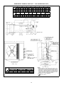
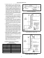
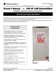
1
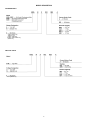
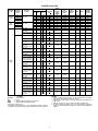
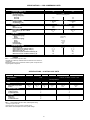
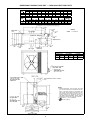
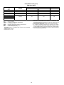
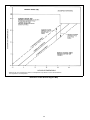
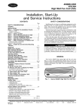
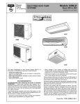
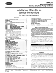
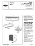
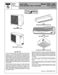
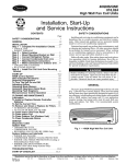
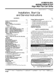
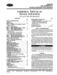
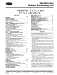
Bryant
Day & Night
Payne
Model 619E
HIGH WALL DUCT-FREE,
SPLIT SYSTEMS
Sizes 009-024
Air Conditioning
⁄ to 2 Tons
34
PRELIMINARY PRODUCT DATA
619E
538A
538C/D009,012
538S (048 Shown)
DESCRIPTION
These duct-free split systems cool, heat (heat pump systems
only) dehumidify, circulate, and filter the air — with minimum
maintenance. They are the ideal complement to your ducted
system when it is impractical or prohibitively expensive to use a
ducted system. The outdoor units, when matched with model
619E fan coil units, offer many technological features and reliable operation.
The duct-free split systems are perfect for add-ons, such as an
office or family room addition, and whenever you have special
space requirements; like for a computer room. Or consider ductfree split systems when changes in the cooling load cannot be
handled by the existing system; for instance, when adding heatgenerating equipment to an already air-conditioned space.
Split systems can also be used when adding air conditioning to
spaces that are heated by hydronic or electric heat, and no
ductwork exists. Historical renovations are another application
for which duct-free split systems are well suited, especially
when preserving the looks of the original structure is essential.
When noise is a concern, these whisper-quiet split systems are
your answer because you don’t have to worry about duct
design.
If security is an issue, outdoor and indoor units are connected
only by refrigerant piping to prevent intruders from crawling
through ductwork. Also, since the outdoor units can be installed
6-in. away from outside walls, coils are protected from vandals
and severe weather.
In addition, the compact duct-free split systems take only a few
hours to installl, without any major interruptions to the customers’ workplace or home.
STANDARD SYSTEM FEATURES
HIGH-EFFICIENCY design with SEERs (Seasonal Energy Efficiency Ratios) up to 12.0 and HSPFs (heating seasonal performance factors; heat pump systems only) of 6.8.
MICROPROCESSOR CONTROL for accurate control of the desired comfort level.
EXTENSIVE DIAGNOSTICS alert the user to the existence of
problems.
BUILT-IN RELIABILITY COMPONENTS include a suction-line
accumulator that safeguards the compressor against loss of lubrication, while start capacitors and relays (non-scroll units) assure dependable start-ups, especially during low-voltage
conditions (down to 187 v). High- and low-pressure safety
switches, crankcase heater (non-scroll units), liquid line filter
drier (538A, 538C, 538S), bi-flow liquid line filter drier (538D),
and lock-out protection are also standard on most sizes.
Form No. PDS 619E.09.1
mount the unit on a wall adjacent to a sloping roof. The wall
mount kit is also useful in areas of heavy snowfall or where
space is at a premium. The wall mount kit may be used with any
outdoor unit.
SUGGESTED USE:
• When application requires that outdoor unit be installed above
ground level.
Liquid solenoid valve (sizes 018 and larger) — The valve is
an electrically operated shutoff valve to be installed at the outdoor unit, and closes and opens in response to compressor operation. The valve maintains a column of refrigerant in the liquid
line between compressor operation cycles and is required for
certain long-line applications. The valve should be used with all
long-line applications (over 100 ft).
SUGGESTED USE:
• Whenever long-line applications are used.
The indoor units include protection against freeze-up (heat
pumps), high discharge temperature, and self diagnostics to ensure reliability.
RESTART FUNCTION FOR AUTOMATIC START AFTER A
POWER FAILURE eliminates the need to reset the unit after a
power failure. The unit restarts in the same mode that was operating prior to the power failure and retains the selected set
point as well.
AUTOMATIC AIR SWEEP ensures evenly-distributed air within
the conditioned space for ultimate comfort. The air sweep feature sweeps the air from side to side.
WEATHER-PROTECTED CABINET is protected with a heavy,
galvanized steel coating, then coated again with a layer of zinc
phosphate to which a coat of polyester powder is applied and
baked on. This provides each unit with a hard, smooth finish that
will last for many years.
All screws on the cabinet exterior are coated for long-lasting,
rust-resistant, quality appearance.
TOTALLY ENCLOSED FAN MOTOR means greater reliability
under rain conditions and dependable performance for many
years. Permanent-split-capacitor-type motors provide the most
economical operation.
REFRIGERANT SYSTEM is designed to provide dependability.
Each unit leaves the factory with a refrigerant charge. Additional
charge may be necessary depending on the application. Refrigerant service connections make checking operating pressures
easier. For precise refrigerant control, all 538A, 538C, and 538D
fan coil units feature an AccuRaterT piston in the fan coil unit,
and 009,012 units feature a capillary in the outdoor unit.
Low-Ambient Temperature Controls (down to −20 F) (538A,
538C, 538D) — The low-ambient kit is a solid-state head pressure controller designed to control outdoor fan cycling, and is
activated by a pressure sensor. It is specifically designed to control fan-motor cycles in response to saturated condensing pressure. This device maintains a constant saturated condensing
temperature of 100 F ± 10 F at outdoor-air temperatures between 55 F and −20 F, and may be used on all 538A, 538C, and
538D outdoor units without changing the outdoor-fan motor.
SUGGESTED USE:
• Applications where a significant amount of unit cooling operation is necessary at outdoor-air temperatures below 55 F.
Crankcase Heater — Crankcase heaters are only an accessory for those units with scroll compressor(s). Heaters are
standard on units with reciprocating compressors.
SUGGESTED USE:
• Scroll compressor applications where an accessory lowambient kit has been installed.
FIELD-INSTALLED ACCESSORY
DESCRIPTION AND USAGE
Condensate Pump — The pump provides condensate lift capability, and is an accessory for the fan coil units.
SUGGESTED USE:
• The condensate pump accessory is recommended when adequate drain line pitch cannot be provided.
Winter Start Control (538A, 538S) — This condensing unit accessory is a single-pole, single-throw delay relay which bypasses the low-pressure switch for approximately 3 minutes to
permit start-up for cooling operation under low load conditions
at low-ambient temperatures.
SUGGESTED USES:
• Applications where low-ambient cooling is required below
40 F outdoor-air temperature.
CONTENTS
Page
Model Description . . . . . . . . . . . . . . . . . . . . . . . . . . . 4
System Capacities . . . . . . . . . . . . . . . . . . . . . . . . . . . 5
Specifications . . . . . . . . . . . . . . . . . . . . . . . . . . . . . 6-8
Dimensional Drawings . . . . . . . . . . . . . . . . . . . . . . . 9-14
Electrical Data . . . . . . . . . . . . . . . . . . . . . . . . . . . . 15,16
Typical Installation . . . . . . . . . . . . . . . . . . . . . . . . . .17,18
Application Data . . . . . . . . . . . . . . . . . . . . . . . . . . 19-23
Typical Wiring Schematics . . . . . . . . . . . . . . . . . . . . 24-27
Operating Sequence . . . . . . . . . . . . . . . . . . . . . . . . 28-30
Engineers’ Specification Guide . . . . . . . . . . . . . . . . . 31,32
Wall mount kit — The kit includes brackets to be mounted to
the outside of the structure to raise unit from ground level, or to
2
STANDARD FEATURES AND FIELD-INSTALLED ACCESSORIES
STANDARD FEATURE/FIELD-INSTALLED
ACCESSORY
Internal Condensate Pump
Mounting Brackets
Microprocessor Controls
Cleanable Filters
3-Speed Indoor-Fan Motor
Automatic Indoor-Fan Speed Control
Extensive Diagnostics
Wireless Remote Controllers
Fully Insulated Indoor Unit Cabinet
Automatic Air Sweep
Auto. Restart Function
24-Hour Automatic Start/Stop Timer
Refrigerant Line Turn Elbow*
High- and Low-Voltage Terminal Blocks (Indoor)
AccuRaterT Refrigerant Metering Device
Manual Defrost**
Demand Defrost**
Warm Start (in heating)**
Heating Operation to −20 F**
Auto. Changeover from Cooling to Heating**
Evaporator Coil Freeze Protection
Outdoor Low-Voltage Terminal Block
Accumulator
Crankcase Heater (Reciprocating Compressor Units)
Crankcase Heater (Scroll Compressor Units)
High-Pressure Switch*
Low-Pressure Switch*
5-Year Compressor Warranty
Compressor Start Assistance (non-scroll units)
Cycle-LOC™ Device*
Suction and Discharge Service Taps††
Totally Enclosed Fan Motor
Acoustically-Lined Compressor Compartment
Winter Start Control*
Low Ambient Temperature Controls (down to −20 F)†
Time GuardT Cycle Protector*
Liquid Solenoid Valve*
Condensing Unit Wall Mount Kit
LEGEND
A — Field-Installed Accessory
S — Standard from the Factory
*For size 018 and larger.
†Not used on 38HDS systems.
**Heat pump systems only.
††The outdoor units are equipped with 4 taps; one for each service valve, and one each
on compressor suction and discharge.
3
HIGH WALL
SYSTEMS
(619B,D)
A
S
S
S
S
S
S
S
S
S
S
S
S
S
S†
S
S
S
S
S
S
S
S
S
A
S
S
S
S
S
S
S
S
A
A
S
A
A
MODEL DESCRIPTION
OUTDOOR UNITS
*009 systems only.
†538C,D only.
**538A, 538D only.
††538A, 538D, 538S only.
\538S only.
FAN COIL UNITS
*009 systems ony.
4
SYSTEM CAPACITIES
SYSTEM
TYPE
NOMINAL
SYSTEM
CAPACITY
(Tons)
⁄
1
11⁄2
2
3⁄4
1
11⁄2
2
INDOOR SECTIONS
FAN COIL
TYPE(S)
34
Cooling
Only
Heat
Pump
2
High Wall
High Wall
High Wall
In-Ceiling Cassette
High Wall
Ceiling Suspended
High Wall
High Wall
High Wall
High Wall
MultiSplit
4
Decibels
Ckt
HSPF
SEER
—
—
—
—
High Wall
High Wall
Ceiling-Suspended
High Wall
High Wall
In-Ceiling Cassette
High Wall
Ceiling Suspended
High Wall
In-Ceiling Cassette
High Wall
Ceiling Suspended
In-Ceiling Cassette
Ceiling Suspended
Ceiling Suspended
High Wall
Ceiling Suspended
In-Ceiling Cassette
High Wall
In-Ceiling Cassette
In-Ceiling Cassette
High Wall
In-Ceiling Cassette
Ceiling Suspended
High Wall
High Wall
In-Ceiling Cassette
High Wall
Ceiling Suspended
High Wall
In-Ceiling Cassette
High Wall
Ceiling Suspended
Ceiling Suspended
High Wall
Ceiling Suspended
In-Ceiling Cassette
High Wall
Ckt
Qty
—
—
—
—
—
—
—
—
A
A
A
A
A
A
B
A
B
A
B
A
B
B
A
B
B
A
B
A
B
A
B
B
A
B
B
A
B
B
A
B
B
A
B
B
A
B
A
B
A
B
A
B
A
B
A
A
B
1
1
1
1
1
1
1
1
2
1
1
1
1
2
2
1
2
1
1
2
1
1
2
1
1
2
2
2
2
2
1
1
2
1
1
2
1
1
2
1
1
2
1
1
2
1
2
1
1
1
1
1
2
1
1
1
1
Model
No. 619
E
E
E
E
E
E
E
E
E
F
E
C
E
E
E
E
E
E
E
E
E
C
E
E
F
E
C
E
F
E
C
F
C
C
E
C
F
E
F
F
E
F
C
E
E
F
E
C
E
F
E
C
C
E
C
F
E
009
012
018
024
009
012
018
024
018
024
018
024†
018
018
018
024
018
024
024
018
018
024†
018
018
024
018
024†
018
024
018
024†
024
024†
024†
018
024†
024
018
024
024
018
024
024†
018
018
036
018
024
024
036
024
024
024†
024
024†
024
024
OUTDOOR
SECTION
538
A 009
A 012
C 018
C 024
D 009
D 012
D 018
D 024
S 024
TOTAL
STANDARD
CFM (AT
HIGH
SPEED)
286
358
534
521
293
350
502
574
1000
SYSTEM
NET
COOLING
(Btuh)
SYSTEM
NET
HEATING
(Btuh)*
SEER
HSPF*
OUTDOOR
SOUND
RATING
(Decibels)
8,500
11,800
17,300
22,600
9,000
12,500
17,300
23,200
23,000
—
—
—
—
9,000
12,500
16,900
21,400
—
10.5
11.0
11.5
12.0
10.5
10.5
11.5
11.0
11.0
—
—
—
—
6.8
6.8
6.8
6.8
—
65
65
70
68
65
65
70
68
68
S
024
1059
23,000
—
11.0
—
68
S
024
1034
23,000
—
11.0
—
68
S
048
1068
46,000
—
11.0
—
72
S
048
1589
46,000
—
11.0
—
72
S
048
1042
46,000
—
11.0
—
72
S
048
2102
46,000
—
11.0
—
72
S
048
2127
46,000
—
11.0
—
72
S
048
2068
47,000
—
11.0
—
72
S
048
2118
46,000
—
11.0
—
72
S
048
2059
46,000
—
11.0
−
72
S
048
2034
47,000
—
11.0
—
72
S
048
2059
47,000
—
11.0
—
72
S
048
2109
46,000
—
11.0
—
72
S
048
2084
46,000
—
11.0
—
72
S
048
1983
47,000
—
11.0
—
72
S
048
1668
45,800
—
11.0
—
72
S
048
1521
46,800
−
11.0
—
72
S
048
1559
45,800
—
11.0
—
72
S
048
1436
46,800
—
11.0
−
72
S
048
1121
45,600
—
11.0
—
72
LEGEND
Sound Levels
Circuit
Heating Seasonal Performance Factors
Seasonal Energy Efficiency Ratio
NOTES:
1. Rating condition is 80 F db, 67 F wb air entering indoor air section
and 95 F db air entering outdoor air section.
2. Total kW is for total system, including compressor and outdoor and
indoor fans.
3. Ratings are based on 25 ft of interconnecting refrigerant line.
4. All system ratings are based on fan coil units operating at high fan
speed. Consult Specifications tables for airflows at all available fan
speeds.
*Heat pump systems only.
†Unit must be reconfigured for 11⁄2 ton (18,000 Btuh) operation. Refer to
installation instructions included with the fan coil unit for more details.
5
SPECIFICATIONS — 538A AND 538C CONDENSING UNITS
UNIT
NOMINAL CAPACITY (Tons)
OPERATING WEIGHT (lb)
REFRIGERANT TYPE
Control (Cooling)
Factory Charge (lb)*
COMPRESSOR TYPE
Model
OUTDOOR FAN
Rpm
Nominal Air Cfm (High Speed)
OUTDOOR COIL
Face Area (sq ft)...No. of Rows
Fins/in.
CONTROLS
High-Pressure (psig)
Cutout
Cut-in
Low-Pressure (psig)
Cutout
Cut-in
Fusible Plug
Control Voltage†
REFRIGERANT LINES
Connection Type
Liquid Line OD (in.)
Vapor Line OD (in.)
Maximum Length (ft)
Maximum Lift (Fan Coil Above Outdoor) (ft)
Maximum Lift (Fan Coil Below Outdoor) (ft)
EXTERNAL FINISH
538C
009
⁄
55.0
538C 012
1
62.0
34
538A 018
11⁄2
150
538A 024
2
154
R-22
Capillary
AccuRaterT Piston at Fan Coil Unit
4.6
5.3
Tecumseh
Copeland
Carlyle Rotary
Reciprocating
Scroll
EAA090111A
EBB120111A
AW5517G
ZR23K1
Propeller Type
1050
1050
850
850
—
—
1720
1720
Copper Tube, Aluminum Fin
3.5...1
3.5...2
6.1...1.5
6.1...2
18
18
15
15
1.5
1.5
—
—
—
—
426 ± 7
320 ± 20
—
—
210 F
115
—
—
210 F
230
7± 3
22 ± 5
210 F
24
Flare
⁄
⁄
35
16
30
Sweat
⁄
⁄
35
16
30
14
14
12
12
Grey
*See System Piston Guide and Refrigerant Charges tables in Application section on page 21 for proper
charge and piston with each fan coil type. Charge is based on duct-free fan coil requiring smallest
amount of refrigerant and 25 ft of interconnecting line.
†24 v and a minimum of 40 va is provided in the fan coil unit.
6
⁄
⁄
200
65
150
⁄
⁄
200
65
150
38
38
58
58
Alpine Mist (Beige)
SPECIFICATIONS — 538D HEAT PUMP UNITS
UNIT 538D
NOMINAL CAPACITY (Tons)
OPERATING WEIGHT (lb)
REFRIGERANT TYPE
Control (Cooling)
Control (Heating)
Factory Charge (lb)*
COMPRESSOR TYPE
Model
OUTDOOR FAN
Rpm (Cooling and Heating)
Nominal Air Cfm (High Speed)
OUTDOOR COIL
Face Area (sq ft)...No. of Rows
Fins/in.
CONTROLS
High-Pressure (psig)
Cutout
Cut-in
Liquid Line Low-Pressure (psig)
Cutout
Cut-in
Fusible Plug
Defrost Method†
Accumulator
Control Voltage**
REFRIGERANT LINES
Connection Type
Mixed Phase Line OD (in.)
Suction Line OD (in.)
Maximum Length (ft)
Maximum Lift (Fan Coil Above Outdoor) (ft)
Maximum Lift (Fan Coil Below Outdoor) (ft)
EXTERNAL FINISH
009
3 ⁄4
60.7
012
1
66.6
018
11⁄2
154
024
2
167
R-22
Fixed Orifice at Outdoor Unit
AccuRaterT Piston at Fan Coil Unit
Fixed Orifice at Outdoor Unit
AccuRater Piston at Outdoor Unit
1.5
2.0
5.0
5.1
Carlyle Rotary
Tecumseh Reciprocating
EBA095111H
EBB130111H
AW5519G
AW5524G
Propeller Type
Propeller, Direct Drive
1050
1050
850
850
—
—
1720
1720
Copper Tube, Aluminum Fin
3.5...1
3.5...2
6.1...1.5
6.1...2
18
18
15
15
—
—
—
—
320 ± 20
426 ± 7
—
—
—
—
210 F
210 F
Time and Temperature Defrost
Yes
Yes
115
230
7± 3
22 ± 5
210 F
Time and Temperature Defrost
Yes
24
Flare
Sweat—Suction; Flare—Liquid
3 ⁄8
3 ⁄8
5 ⁄8
5 ⁄8
200
200
65
65
150
150
Alpine Mist (Beige)
⁄
⁄
35
16
30
⁄
⁄
35
16
30
14
14
12
12
Grey
*Units are shipped with charge listed (smallest applicable system charge). Refer to Piston Guide tables on page 21
for proper charge for your application.
†Demand defrost.
**A 24-v transformer is provided in the 018, 024 fan coil unit.
7
SPECIFICATIONS — 538S CONDENSING UNITS
UNIT 538S
NOMINAL CAPACITY (Tons)
OPERATING WEIGHT (lb)
REFRIGERANT TYPE
Control (Cooling)
Factory Charge (lb)*
Circuit A
Circuit B
COMPRESSOR TYPE
Quantity...Model
Oil (Recharge) (oz)
OUTDOOR FAN
Rpm
Nominal Air Cfm
OUTDOOR COIL
Face Area (sq ft)...No. of Rows
Fins/in.
CONTROLS
High-Pressure (psig)
Cut-in
Cutout
Low-Pressure (psig)
Cut-in
Cutout
Fusible Plug
Control Voltage
REFRIGERANT LINES
Connection Type
Vapor Supply Line Quantity...OD (in.)
Vapor Return Line Quantity...OD (in.)
Maximum Length (ft)
Maximum Lift (Fan Coil Above Outdoor) (ft)
Maximum Lift (Fan Coil Below Outdoor) (ft)
EXTERNAL FINISH
024
2
159
048
4
292
R-22
TXV in Condensing Unit
5.0
—
5.5
5.5
Copeland Scroll
1...ZR23K1
25
2...ZR23K1
25
Propeller, Direct Drive
850
1720
850
3900
Copper Tube, Aluminum Fin
6.1...2
15
12.3...2
15
320 ± 20
426 ± 7
22 ± 5
7±3
210 F
24
Sweat
2...3⁄8
2...5⁄8
50
30†
30†
4...3⁄8
4...5⁄8
50
30†
30†
Alpine Mist (Beige)
LEGEND
TXV — Thermostatic Expansion Valve
*Charges are preliminary estimates and are based on 25 ft of interconnecting line.
†Maximum system lift is 30 ft between lowest system component and
highest system component.
SPECIFICATIONS — 619E FAN COIL UNITS
UNIT 619E
OPERATING WEIGHT (lb)
REFRIGERANT**
FAN
Rpm
Nominal Cfm (High Speed)
COIL
Face Area (sq ft)...Rows
Fins/in.
CONNECTIONS (MPT)
Vapor (in.) Flare
Liquid (in.) Flare
Condensate Drain
LINE SIZES
Vapor (in.)
Liquid (in.)
Condensate Drain
009*
18.7
012*
24.2
009†
18.7
012†
24.2
R-22
1250
215
1150
302
1250
252
1.45...2
18
1.60...3
17
1.45...2
18
Centrifugal Blower
1150
302
1.60...3
17
018
024
39
43
R-22 with AccuRaterT Control or TXV
1300
480/455**
1505
550/525**
2.56...2
15.9
2.56...3
18.1
12
⁄
⁄
5 ⁄8
58
14
38
⁄
⁄
5 ⁄8
12
⁄
⁄
5 ⁄8
58
14
38
⁄
⁄
⁄
58
LEGEND
TXV — Thermostatic Expansion Valve (538S Systems Only)
*Cooling-only fan coil unit.
†Heat pump fan coil unit. Cooling only/Heat pump.
**See outdoor unit nameplate for correct system charge.
8
DIMENSIONAL DRAWING, BASE UNIT — 538C/D009,012 COOLING ONLY AND HEAT PUMP UNITS
NOTES:
1. Dimensions in [ ] are in millimeters.
2.
Direction of airflow.
3.
Center of gravity.
4. Minimum clearances, 4 in. on coil sides, 24 in. on fan
side, and 30 in. service side.
UNIT
538
C 009
C 012
D 009
D 012
9
WEIGHT
Lb
55.0
62.0
60.7
66.5
Kg
25.0
28.1
27.5
30.2
DIMENSIONAL DRAWING — BASE UNIT — 538A018-024 CONDENSING UNITS
A
B
C
D
E
F
G
H
UNIT
538A ft-in. mm ft-in.
mm
ft-in. mm ft-in. mm
ft-in.
mm ft-in. mm ft-in. mm ft-in. mm
018 2-11⁄8 638.2 3-015⁄16 938.2 1-29⁄16 369.9 1-4 406.4 1-117⁄16 595.3 1-53⁄16 436.6 1-51⁄2 444.5 1-81⁄8 511.2
024 2-11⁄8 638.2 3-015⁄16 938.2 1-29⁄16 369.9 1-4 406.4 1-117⁄16 595.3 1-53⁄16 436.6 1-51⁄2 444.5 1-81⁄8 511.2
UNIT
538A
018
024
J
K
L
ft-in. mm ft-in. mm
ft-in.
1-11⁄4 336.6 0-65⁄8 168.3 0-1013⁄16
1-27⁄16 366.7 0-63⁄4 171.4 1- 0
OPERATING
WT
mm ft-in. mm ft-in. mm ft-in. mm ft-in. mm
Lb
kg
274.6 0-05⁄8 15.00 0-03⁄8 9.52 0-41⁄2 115.0 0-61⁄2 166.0 150
68.0
304.8 0-05⁄8 15.00 0-03⁄8 9.52 0-41⁄2 115.0 0-61⁄2 166.0 154
69.0
M
N
R
S
MINIMUM MOUNTING PAD DIMENSIONS
Support Feet
Snow Stand
Ice Stand
ft-in.
mm
ft-in.
mm
ft-in.
mm
1-11 x
584.2 x
2-2 x
660.4 x
2-2 x
660.4 x
3-6
1066.8
3-6
1066.8
3-6
1066.8
NOTES:
1. Required clearances, with coil facing wall, allow
6 in. minimum clearance on coil side and coil end,
and 3 ft minimum clearance on compressor end
and fan side. With fan facing wall, allow 8 in. minimum clearance on fan side and coil end, and 3 ft
minimum clearance on compressor end and coil
side. With multi-unit application, arrange units so
discharge of one does not enter inlet of another.
2. Dimensions in parenthesis are in millimeters.
3.
10
Center of Gravity.
DIMENSIONAL DRAWING, BASE UNIT — 538D018,024 HEAT PUMP UNITS
UNIT
538D
018
024
UNIT
538D
018
024
A
ft-in.
2-11⁄8
2-11⁄8
G
B
mm
638.2
638.2
ft-in.
3-015⁄16
3-015⁄16
H
C
mm
938.2
938.2
ft-in.
1-29⁄16
1-29⁄16
D
mm
369.9
369.9
J
K
ft-in.
1-4
1-4
mm
406.4
406.4
L
ft-in. mm ft-in. mm ft-in. mm ft-in. mm ft-in.
1-51⁄2 444.5 1-81⁄8 511.2 1-1 330.2 0-65⁄8 168.3 0-111⁄4
1-51⁄2 444.5 1-81⁄8 511.2 1-1 330.2 0-63⁄4 171.5 0-115⁄8
E
ft-in.
mm
1-117⁄16 595.3
1-117⁄16 595.3
F
ft-in.
1-53⁄16
1-53⁄16
mm
436.6
436.6
OPERATING
WEIGHT
mm ft-in. mm
lb
Kg
285.8 0-05⁄8 15.88 154
69.8
295.3 0-05⁄8 15.88 167
75.7
M
LEGEND
CONN — Connection
MINIMUM MOUNTING PAD DIMENSIONS
Support Feet
Snow Stand
Ice Stand
ft-in.
mm
ft-in.
mm
ft-in.
mm
1-11 x
584.2 x
2-2 x
660.4 x
2-2 x
660.4 x
3-6
1066.8
3-6
1066.8
3-6
1066.8
NOTES:
1. Required clearances, with coil facing wall; allow
6 in. minimum clearance on coil side and coil end,
and 3 ft minimum clearance on compressor end
and fan side. With fan facing wall; allow 8 in. minimum clearance on fan side and coil end, and 3 ft
minimum clearance on compressor end and coil
side. With multi-unit application; arrange units so
discharge of one does not enter inlet of another.
2. Dimensions in [ ] are in millimeters.
3.
11
Center of gravity.
DIMENSIONAL DRAWING, BASE UNIT — 538S CONDENSING UNITS
UNIT
538S
024
048
UNIT
538S
024
048
UNIT
538S
024
048
A
B
C
D
E
F
G
H
Ft-in. mm Ft-in. mm Ft-in. mm Ft-in. mm Ft-in. mm Ft-in. mm Ft-in. mm Ft-in. mm
406 1-117⁄16 595 1-53⁄16 437 1-51⁄2 445 1-81⁄8 511
2-11⁄8 638 3-015⁄16 938 1-29⁄16 370 1-4
3-13⁄16 945 3-89⁄16 1132 1-51⁄16 433 1-67⁄16 468 2- 61⁄2 775 1-75⁄8 499 2-55⁄8 753 2-83⁄16 818
OPERATING
WEIGHT
Ft-in. mm Ft-in. mm Ft-in. mm Ft-in. mm Ft-in. mm Ft-in. mm Ft-in. mm Lb
Kg
—
—
—
— 159
72.0
1-27⁄16 367 0-63⁄4 171 1-0 305 0-05⁄8 16 0-03⁄8 10
1-23⁄4 375 0-71⁄2 191 1-6 457 0-05⁄8 16 0-03⁄8 10 0-65⁄16 160 0-57⁄8 149 292 132.3
J
K
L
M
N
MINIMUM MOUNTING PAD DIMENSIONS
SUPPORT FEET
SNOW STAND
ICE STAND
Ft-in.
mm
Ft-in.
mm
Ft-in.
mm
1-11 x 3-6 584 x 1067 2-2 x 3-6 660 x 1067 2-2 x 3-6 660 x 1067
2-0 x 4-2 610 x 1270 2-4 x 4-4 711 x 1270 2-2 x 4-2 660 x 1270
12
R
S
NOTES:
1. Required clearances: with coil facing wall; allow 6 in. minimum clearance on coil side and coil end, and 3 ft minimum
clearance on compressor end and fan side. With fan facing
wall; allow 8 in. minimum clearance on fan side and coil
end, and 3 ft minimum clearance on compressor end and
coil side. With multi-unit application: arrange units so discharge of one does not enter inlet of another.
2. Dimensions in [ ] are in millimeters.
3.
Center of gravity.
DIMENSIONAL DRAWING, BASE UNIT — 619E009,012 FAN COIL UNITS
UNIT
619E
009
012
WEIGHT
Lb
Kg
18.7
8.5
24.2 11.0
A
in.
mm
33.46 850
36.61 930
B
in.
mm
11.02 280
11.81 300
C
in.
6.29
7.28
mm
160
185
NOTES:
1. Dimensions are in inches. Dimensions in [
2.
Direction of airflow.
] are in millimeters.
3. Refrigerant, drain and power connections may be made rear, left side or right side.
4. Refrigerant is metered by capillary tubes in the outdoor unit. Insulate both refrigerant lines.
5. Clearances of 31⁄29 on top and to the left of the fan coil unit are absolute minimums.
Clearances of 109 are recommended.
13
DIMENSIONAL DRAWING, BASE UNIT — 619E018,024 FAN COIL UNITS
UNIT
619E
018
024
WEIGHT
39 Lb [17.5 Kg]
43 Lb [19.5 Kg]
NOTES:
1. Dimensions in [ ] are in millimeters.
2.
Direction if airflow.
3. Refrigerant, drain, and power connections may be made in unit rear, bottom,
left side, or right side.
4. Refrigerant is metered by AccuRaterT device at the fan coil unit on 538A and
538D018,024 applications. A thermostatic expansion valve is used in the outdoor unit on 538S applications. Insulate both refrigerant lines on 538S and
538D018,024 applications.
5. The 49 top and left clearances are absolute minimums. Clearances of 109 are
recommended.
14
ELECTRICAL DATA
CONDENSING UNITS
UNIT
VOLTAGE
(Single Ph, 60 Hz)
538A 018
538A 024
538C 009
538C 012
OPERATING
VOLTAGE
MINIMUM*
OPERATING
VOLTAGE
MAXIMUM*
208/230
187
254
115
208/230
104
187
127
253
LEGEND
FLA
— Full Load Amps
HACR — Heating, Air Conditioning, Refrigeration
LRA
— Locked Rotor Amps
MCA — Minimum Circuit Amps per NEC Section 430-24
NEC
— National Electrical Code
RLA
— Rated Load Amps (Compressor)
*Permissible limits of the voltage range at which unit will operate
satisfactorily.
†Cooling only fan coil unit.
**Heat pump fan coil unit.
COMP
RLA
FAN
FLA
8.0
12.9
7.6
5.5
0.70
0.76
0.35
POWER
MCA†
MOCP†
10.7
16.8
12.1
8.5
15
25
15
15
NOTES:
1. The 018 and 024 outdoor units contain a 24-v transformer; additional
transformers are not required. The 009, 012 outdoor units use high
voltage controls.
2. All motors and compressors contain internal overload protection.
3. In compliance with NEC requirements for multimotor and combination load equipment (refer to NEC Articles 430 and 440), the overcurrent protective device for the unit shall be fuse or HACR breaker.
4. Motor RLA values are established in accordance with UL (Underwriters’ Laboratories) Standard 1995.
HEAT PUMP UNITS
115
208/230
OPERATING
VOLTAGE
MINIMUM*
104
187
OPERATING
VOLTAGE
MAXIMUM*
127
254
208/230
187
254
UNIT
538D
VOLTAGE
(Single Ph, 60 Hz)
009
012
018
024
LEGEND
FLA
— Full Load Amps
HACR — Heating, Air Conditioning, Refrigeration
LRA
— Locked Rotor Amps
MCA — Minimum Circuit Amps per NEC Section 430-24
NEC
— National Electrical Code
RLA
— Rated Load Amps (Compressor)
*Permissible limits of the voltage range at which unit will operate
satisfactorily.
†Cooling only fan coil unit.
**Heat pump fan coil unit.
COMP
RLA
FAN
FLA
9.0
5.8
9.8
11.7
0.76
0.35
0.70
POWER
MCA
MOCP
11.2
13.9
13.0
15.3
15
15
20
25
NOTES:
1. The 018 and 024 outdoor units contain a 24-v transformer; additional
transformers are not required. The 009, 012 outdoor units use high
voltage controls.
2. All motors and compressors contain internal overload protection.
3. In compliance with NEC requirements for multimotor and combination load equipment (refer to NEC Articles 430 and 440), the overcurrent protective device for the unit shall be fuse or HACR breaker.
4. Motor RLA values are established in accordance with UL (Underwriters’ Laboratories) Standard 1995.
MULTI-SPLIT CONDENSING UNITS
UNIT SIZE
538S
V-PH-Hz
OPERATING
VOLTAGE
MINIMUM*
OPERATING
VOLTAGE
MAXIMUM*
024
048
208/230-1-60
187
254
COMPRESSOR
FAN
Quantity
RLA
(Ea)
LRA
(Ea)
FLA
MCA
1
2
12.9
62.5
0.70
1.45
16.8
30.5
LEGEND
FLA
— Full Load Amps
HACR — Heating, Air Conditioning, Refrigeration
LRA
— Locked Rotor Amps
MCA — Minimum Circuit Amps per NEC Section 430-24
NEC
— National Electrical Code
RLA
— Rated Load Amps (Compressor)
*Permissible limits of the voltage range at which unit will operate
satisfactorily.
†Cooling only fan coil unit.
**Heat pump fan coil unit.
POWER SUPPLY
Max Fuse
or HACR-Type
Circuit Breaker Amps
25
40
NOTES:
1. The 024 and 048 outdoor units contain a 24-v transformer; additional
transformers are not required.
2. All motors and compressors contain internal overload protection.
3. In compliance with NEC requirements for multimotor and combination load equipment (refer to NEC Articles 430 and 440), the overcurrent protective device for the unit shall be fuse or HACR breaker.
4. Motor RLA values are established in accordance with UL (Underwriters’ Laboratories) Standard 1995.
15
ELECTRICAL DATA (cont)
FAN COIL UNITS
INDOOR
UNIT
619E
009†
012†
009**
012**
018†
024†
018**
024**
OPERATING VOLTAGE*
FAN
V (SinglePh, 60 Hz)
Minimum
Maximum
FLA
115
208/230
115
208/230
104
187
104
187
127
253
127
253
—
—
—
—
208/230
187
253
0.53
LEGEND
FLA
— Full Load Amps
HACR — Heating, Air Conditioning, Refrigeration
LRA
— Locked Rotor Amps
MCA — Minimum Circuit Amps per NEC Section 430-24
NEC
— National Electrical Code
RLA
— Rated Load Amps (Compressor)
*Permissible limits of the voltage range at which unit will operate
satisfactorily.
†Cooling only fan coil unit.
**Heat pump fan coil unit.
NOTES:
1. The 018, 024, 048 outdoor units contain a 24-v transformer; additional transformers are not required. The 009, 012 outdoor units use
230-v (high voltage) controls.
2. All motors and compressors contain internal overload protection.
3. In compliance with NEC requirements for multimotor and combination load equipment (refer to NEC Articles 430 and 440), the overcurrent protective device for the unit shall be fuse or HACR breaker.
4. Motor RLA values are established in accordance with UL (Underwriters’ Laboratories) Standard 1995.
16
TYPICAL INSTALLATION — HIGH-WALL SYSTEMS, 9,000 AND 12,000 BTUH
(Cooling-Only System Shown)
LEGEND
NEC — National Electrical Code
*Standard.
†Field supplied.
NOTES:
1. All piping must follow standard refrigerant techniques.
2. Do not install a filter drier in mixed phase liquid line.
3. All wiring must comply with applicable local and national codes.
4. Capillary tube expansion device (cooling-only systems only) is located in the
outdoor unit. Both refrigerant lines must be insulated.
5. Wiring and piping shown are general points-of-connection guides only and are
not intended to include all details for a specific installation.
6. Insulate condensate line drain if installed in a conditioned space.
17
TYPICAL INSTALLATION — HIGH-WALL SYSTEMS, 18,000 AND 24,000 BTUH
(Cooling Only System Shown)
LEGEND
NEC — National Electrical Code
Piping
Line Voltage
24 V
Thermistor
*Standard.
†Field supplied.
NOTES:
1. All piping must follow standard
refrigerant piping techniques.
2. All wiring must comply with the
applicable local and national
codes.
3. Liquid line need not be insulated.
4. Wiring and piping shown are general points-of-connection guides
only and are not intended for a
specific installation.
5. Insulate condensate drain if installed in a conditioned space.
18
APPLICATION DATA
5. Mounting template
The fan coil units are furnished with a mounting template to
mark the location of the mounting brackets, wiring, and refrigeration hole locations.
1. Unit selection
Select equipment to either match or be slightly less than anticipated peak load. This provides better humidity control,
fewer unit cycles, and less part-load operation.
For units used in spaces with high sensible loads, base
equipment selection on unit sensible load, not on total anticipated load. Adjust for anticipated room wet bulb temperature to avoid undersizing equipment.
For heat pump systems, heating load using outdoor air
must be checked in addition to cooling load. Heating load of
outdoor air can greatly reduce heating capability.
For heat pump systems, heating and cooling design loads
must both be checked.
When selecting equipment which has outdoor air introduced into the unit, determine the mix conditions of room air
and outdoor air at design conditions. The cooling capacity
tables in this literature are based on 80 F edb. Adjust for actual dry-bulb and wet-bulb conditions with the required outdoor air to select the proper equipment.
6. Support
Adequate support must be provided to support the weight
of all fan coils. Refer to the Specification tables on
page 8 for fan coil weights, and the base unit dimensional
drawings on pages 13 and 14 for the location of mounting
brackets.
7. System operating conditions
Operating limits:
OUTDOOR UNITS
CONDITION
Maximum Cooling Ambient (F)
Minimum Cooling Ambient (F) (without
accessory low-ambient kit)
Minimum Cooling Ambient (F) (with
accessory low-ambient kit)
Minimum Cooling Return-Air Temperature (F)
Maximum Cooling Return-Air Temperature (F)
Maximum Heating Return-Air Temperature (F)*
Minimum Heating Return-Air Temperature (F)*
Maximum Heating Ambient Temperature (F)*
Minimum Heating Ambient Temperature (F)
Saturated Suction Temperature Range
Minimum (F)
Maximum (F)
Saturated Condensing Temperature Range
Minimum (F)
Maximum (F)
Maximum Compressor Discharge
Temperature (F)
Minimum Discharge Superheat (F)
2. Unit combinations and coil mixed matches
The 538A, 538C, 538D, and 538S units are the only units
approved for use with the 619E duct-free split systems.
These outdoor units may also be used with other fan coil
units.
3. Unit mounting (outdoor)
a. Unit leveling — For reliable operation, units should be
level in all planes.
b. Clearance — Adequate clearance must be provided for
airflow. See dimensional drawings for proper clearances. The outdoor units are designed for free-blow application. Air inlets and outlets should not be restricted.
Outdoor fan external static pressure available is less
than 0.1 in. wg.
c. Unit location — Cooling units may be stacked 2 high.
Units may be wall mounted, pad mounted at ground
level, roof mounted, mounted on or under a deck, or
mounted on a patio. Be sure water drainage from roof
will not drain directly onto the unit.
NOTE: If stacking units is desired (538A, 538C, 538S only),
field-fabricated and installed hardware is required. Contact
your local representative for details.
If 018, 024, 048 units are being mounted near a wall, the
outdoor-air section should discharge toward the wall. This
will provide inherent coil protection and the best possible
sound and airflow performance. The 009, 012 units should
be mounted with fan discharge pointing away from the wall.
009,012
125
018,024,048
125
55
55
–20
–20
55
95
80/71†
55
0
80
55
95
80/71†
55
−20
80
–15
55
–15
55
85
150
80
150
275
275
60
60
*Heat pump units only.
†Dry bulb/wet bulb.
FAN COIL UNITS
CONDITION
Maximum Room
Temperature (F)
Minimum Room
Temperature (F)
Maximum Return Air (F)
Dry-Bulb
Wet-Bulb
Maximum Saturated
Suction Temperature (F)
Minimum Saturated
Suction Temperature (F)
ALL
UNITS
84
64
85
72
55
27
8. Low-ambient operation
Units can operate in cooling down to 55 F (538A, 538C,
538D) under all conditions without a low-ambient or winter
start kit.
Units equipped with accessory low-ambient or winter start
kits should also be equipped with field-fabricated wind
baffle, field supplied crankcase heater (scroll units only)
and field-supplied isolation relay.
a. Winter start (538C and 538S) — The use of a winter
start control may extend the unit operation range (below
40 F) without addition of the low-ambient kit. Winter start
bypasses the low-pressure switch for 3 minutes.
b. Crankcase heater — Scroll compressor units with lowambient control or winter start should be equipped with
crankcase heaters to prevent refrigerant migration during compressor off cycle.
c. Freezestat (heat pump systems only) — Freeze up
protection is provided on all fan coil units.
4. Unit mounting (indoor)
a. Unit leveling — For reliable operation, units should be
level in all planes.
b. Clearance — Provide adequate clearance for airflow.
The unit return and discharge should not be obstructed
by furniture, curtains, or anything which may cause unit
short cycling or air recirculation. See base unit dimensional drawings on pages 13 and 14 for required
clearances.
c. Unit location — When selecting unit location, select a
location which will provide the best air circulation for the
room.
Position units as high as possible on the wall for best air
circulation. Allow adequate clearances above the unit for
servicing (removing unit covers). Place the unit in the
middle (horizontally) of the wall selected (if possible).
Select an outside wall if available to make piping easier,
and place the unit so it faces the normal location of room
occupants.
19
APPLICATION DATA (cont)
9. Metering devices
a. 009, 012 units — The 009 and 012 units have capillary
tubes for refrigerant metering located in the outdoor condensing unit.
b. 018, 024 units — The 018, 024 units use a piston-type
metering device located in the indoor unit.
NOTE: All 538A, 538C, 538D (018, 024) duct-free split systems use Chattleff style AccuRaterT pistons. DO NOT mix
piston types. All 538D009, 012 systems use Aeroquip type
pistons. See Long-Lines Applications section on page 20
for changes in piston sizes due to long lines.
10. Drain connections
Install drains to meet local sanitation codes. If adequate
gravity drainage cannot be provided, unit should be
equipped with accessory condensate pump. High wall fan
coil unit condensate pumps have a 10 ft lift capability above
the condensate pan level.
See base unit dimensional drawings on pages 13 and 14
for fan coil unit drain locations and sizes.
NOTE: High wall fan coil units have internal condensate
traps.
Drain connections may be routed through alternate locations on most fan coils. See base unit dimensional drawings
on pages 13 and 14 for possible alternate locations.
11. Refrigerant lines
a. General refrigerant line sizing:
1) All charges, line sizing, and capacities are based on
runs of 25 ft. For runs over 25 ft, consult long-lines
section on page 20 for proper line sizing, charge, and
AccuRater refrigerant metering device sizing.
NOTE: For runs less than 25 ft, some of the charge may
need to be removed to obtain the correct system superheat. The minimum line length should be 8 ft.
MAXIMUM LINE LENGTHS
UNIT
MAXIMUM
EQUIVALENT
FT
538A, 538D018,024
538D, 538D009
538C, 538D012
538S
200
35
49
50
MAXIMUM LIFT — MAXIMUM LIFT —
FAN COIL
FAN COIL
BELOW
ABOVE
CONDENSING
CONDENSING
UNIT
UNIT
150
65
35
16
35
16*
30†
30†
*This changes to 25 ft with addition of accessory crankcase heater.
†Maximum distance permitted is 30 ft from lowest system component to
highest system component.
2) Refrigerant lines should not be buried in the ground.
If it is necessary to bury the lines, not more than
36 in. should be buried. Provide a minimum 6-in. vertical rise to the service valves to prevent refrigerant
migration.
3) The vapor line must be insulated. Use a minimum of
1⁄2-in. thick insulation. Closed-cell insulation is recommended in all long-line (over 25 ft) applications.
4) Special consideration should be given to isolating
interconnecting tubing from the building structure.
Isolate the tubing so that vibration or noise is not
transmitted into the structure.
b. 538C,D009,012 units
1) These units are shipped with a charge of R-22 refrigerant. Check the charge using the superheat
20
method. Since all refrigerant lines are on the low side
of the system, it is not normally necessary to add or
remove charge.
2) These units have mixed-phase refrigerant flow in the
liquid line. DO NOT install a filter drier in the liquid
line. The liquid line must be insulated.
3) No line size changes should be made on 009, 012
units.
c. 538A,D018, 024 units
1) These units are shipped with a charge of R-22 refrigerant. See System Piston Guide and Refrigerant
Charges tables on page 21 for system charges. Add
additional charge by weight as necessary and check
the charge with a superheat calculator.
2) For these units, install the filter drier provided with
the unit in the liquid line. Use of a field-supplied moisture indicator is also recommended.
d. 538S units
1) Outdoor units are shipped with the charges listed in
the Specifications — 538S Condensing Units table
on page 8. To determine if additional charge is required, add all charges listed in fan coil unit specifications table(s) in the Product Data literature for your
system (per circuit). The sum of the charges listed is
the system circuit charge required based on 25 ft of
line.
2) For the 538S units, filter driers are provided in the
unit.
3) Vapor supply lines on all 538S units should be 5⁄8 in.
only. DO NOT resize vapor supply lines for additional
length.
4) When sizing vapor return line, determine line length
by finding equivalent ft of tubing. Equivalent line
lengths equal the linear length (measured length) of
the interconnecting vapor return tubing plus losses
due to elbows (see Fitting Loss in Equivalent Ft For
Elbows table on page 21). If the number of elbows is
not yet known, assume 50% additional length for
equivalent length. In determining line size, be sure oil
can be properly returned to the compressor. Contact
your local representative for oil return recommendations as necessary. For line lengths from 25 to 50 ft,
no special tubing requirements are normally required. Adjust charge to required amount by adding
charge per subcooling method. Refer to 538S base
unit installation instructions for charging details.
e. Long-lines applications, 538A,D018,024 units:
1) Liquid lines on all 538A,D018,024 units should be
3⁄8 in. only. DO NOT resize liquid lines for additional
length.
2) When sizing vapor line, determine line length by finding equivalent ft of pipe. Equivalent line lengths
equal the linear length (measured length) of the interconnecting vapor tubing plus losses due to elbows
(see Fitting Loss in Equivalent Ft For Elbows table
on page 21). If the number of elbows is not yet
known, assume 50% additional length for equivalent
length. In determining line size, be sure oil can be
properly returned to the compressor. Consult your local representative for proper oil return recommendations as necessary. For line lengths from 15 to 49 ft,
no special piping requirements are normally
required. Adjust charge to required amount by adding charge per Step l) on page 23 and checking
superheat.
APPLICATION DATA (cont)
3) For line lengths over 50 ft (018,024 only):
a) A crankcase heater should be added to scroll
compressor units (all non-scroll compressor units
have crankcase heaters as standard). Crankcase
heaters help prevent refrigerant migration to the
compressor during the off cycle.
b) Any time the equivalent line length is over 100 ft,
a liquid line solenoid must be used. A liquid line
solenoid may also be required for vertical lift applications over 25 ft. See Step h) on page 22.
c) The accessory wind baffle is recommended.
d) The Effective Capacity Loss table on this page
provides the estimated percentage of nominal
cooling capacity losses based on the standard required vapor line size versus what is selected for
long-line applications.
Select the desired vapor line size from the Effective Capacity Loss table based on equivalent ft
and desired vapor line size.
Subtract the nominal percentage loss from the
unit cooling capacities for the given indoor and
outdoor combination.
FITTING LOSS IN EQUIVALENT FT FOR ELBOWS
90-DEGREE
SHORT
RADIUS
1.6
1.8
TUBE SIZE
O.D. (in.)
⁄
⁄
58
34
90-DEGREE
LONG
RADIUS
1.0
1.2
45-DEGREE
SHORT
RADIUS
0.8
0.9
CHATTLEFF COMMON PISTON SIZES
PISTON SIZE
32
33
35
36
37
38
39
40
41
42
43
45
47
49
51
52
PISTON SIZE
53
55
57
59
61
62
63
65
67
68
70
71
73
74
76
78
PISTON SIZE
80
81
82
84
86
88
89
90
92
93
96
98
101
104
—
—
COOLING ONLY SYSTEM PISTON GUIDE AND REFRIGERANT CHARGES
INDOOR
UNIT
619E
009
012
018
024
OUTDOOR
UNIT
538
C 009
C 012
A 018
A 024
PISTON REQUIRED
(Size)
CHARGE
(Lb)*
None
None
49
57
1.5
1.8
4.6
5.3
NOTES:
1. All 018,024 pistons are Chattleff type.
2. All cooling units have a full factory charge.
3. Service valves are front-seating type.
*Charge based on 25 ft of interconnecting tubing. Charge may need to be added
for longer tubing runs or when used with certain fan coils. Check unit nameplate
for required charge.
HEAT PUMP SYSTEM PISTON GUIDE AND REFRIGERANT CHARGES
UNIT
Indoor
619E
009
012
018
024
Outdoor
538D
009
012
018
024
COOLING
PISTON
SIZE
HEATING
PISTON
SIZE
REQUIRED
SYSTEM
CHARGE (Lb)*
30
42
51
49
32
42
47
52
1.5
2.0
5.0
5.1
*Charge based on 25 ft of interconnecting tubing. Charge may need to be added
for longer tubing runs or when used with certain fan coils. Check unit nameplate
for required charge.
NOTES:
1. All 009,012 pistons are Aeroquip type. All 018,024 pistons are Chattleff type.
2. The 538D heat pumps have a holding charge only as shipped from the
factory.
EFFECTIVE CAPACITY LOSS
NOMINAL
UNIT SIZE*
18,000
24,000
STANDARD
VAPOR LINE (in.)
LONG-LINE
VAPOR LINE (in.)†
⁄
5⁄8
5⁄8
5⁄8
58
58
⁄
3⁄4
5⁄8
3⁄4
50 ft
1
0
2
0
75 ft
3
0
5
0
*Nominal cooling capacity of the unit being specified.
†The vapor line diameter that may be selected for long-line application. If smaller
vapor lines than are specified in the table are selected, a larger capacity loss will
occur. If larger vapor lines are selected, refrigerant oil return will be impaired due
to velocity loss.
**Not recommended due to excessive loss of capacity.
PERCENT COOLING CAPACITY LOSS
100 ft
125 ft
150 ft
4
5
7
1
1
2
8
10
13
1
2
3
175 ft
9
2
**
4
200 ft
10
3
**
5
NOTE: Long-line applications (50 ft and longer) are not permitted on 009, 012
systems.
21
APPLICATION DATA (cont)
e) Changes in piston size — The metering device for a
long-line application must be adjusted to compensate for the frictional losses due to the long refrigerant lines, refrigerant lines accessories, and indoor
coil above or below the outdoor unit. The
AccuRaterT refrigerant metering device piston may
need to be changed to provide this adjustment. The
AccuRater piston should be changed for the indoor
unit depending upon system configuration and line
length. Use the Change in Indoor Unit Piston Size Elevation table on next page to determine correct
AccuRater piston size. The standard piston size is
shown in the System Piston Guide and Refrigerant
Charges tables on page 21.
f) Horizontal configuration — If the total equivalent
horizontal length is 100 ft or longer, the indoor piston
must be increased one full piston size, in addition to
the charge change in Step l), page 23. If exact size is
not available, use next smaller size per Chattleff
Common Piston Sizes table.
g) Elevated configuration — After finding the appropriate change in piston size, add or subtract the
change from the original piston size number. If the
piston size is decreased, round down to the next
common piston size. If the piston size is increased,
round the new piston size up to the next common
piston size.
h) Liquid line solenoid and tubing configuration — The
solenoid has a flow arrow stamped on the valve
body. When the valve is closed (not energized), the
pressure is applied in the direction of the flow arrow,
complete shut off will occur. If pressure is applied
against the direction of the arrow, leakage through
the valve will occur. When determining the proper location for a solenoid in a system liquid line, consider
both flow direction and location of the valve in the
system. See the diagram below for proper location,
and install per sections i), j), and k) below.
i) Horizontal configuration (see figure below) — Install a
biflow (538D only or standard) liquid line solenoid
valve within 2 ft of the fan coil with the flow arrow
pointing toward the indoor unit if equivalent ft of piping is 100 ft or more.
Slope the vapor line toward the indoor unit to provide
for refrigerant migration protection during the off cycle
due to temperature differences caused by slight elevation changes between indoor and outdoor units.
NOTE: When installing a liquid line solenoid, a lowvoltage transformer may be required.
LEGEND
FCU — Fan Coil Unit
OU — Outdoor Unit
*009,012 systems.
†538A,538D018,024 systems.
Horizontal Configuration
*009,012 systems.
†538A,538D018,024 systems.
LEGEND
FCU — Fan Coil Unit
OU — Outdoor Unit
Liquid Line
Solenoid Valve
(if used)
Lowered Configuration — Indoor Unit
Installed Below the Outdoor Unit
CHANGE IN INDOOR UNIT PISTON SIZE
FOR ELEVATION
*009,012 systems.
†538A,538D018,024 systems.
OUTDOOR UNIT ABOVE INDOOR UNIT
Ft
Piston Change
0- 25
0
26- 50
-3
51- 75
-5
76-100
-7
101-125
-9
126-150
-10
INDOOR UNIT ABOVE OUTDOOR UNIT
Ft
Piston Change
0-25
0
26-65
+4
LEGEND
FCU — Fan Coil Unit
OU — Outdoor Unit
Liquid Line
Solenoid Valve
(Required over 25 ft)
Elevated Configuration — Indoor Unit
Installed Above the Outdoor Unit
22
APPLICATION DATA (cont)
and thermistor cable assemblies should not touch each
other, and cable runs may be extended up to 200 ft.
14. Wiring
Use only copper wires from the disconnect to the unit terminal block. Aluminum and copper-clad aluminum wires are
not acceptable.
All duct-free split systems (except the 009,012 outdoor
units) provide 24-v power for the outdoor unit in the ductfree fan coil. The 009,012 outdoor units systems use highvoltage controls.
The 009,012 outdoor units system fan coil units must have
power wires run from the outdoor condensing unit to the indoor unit to prevent out-of-phase wiring.
15. Air throw
Refer to Air Throw Data table below for system air throw
capabilities.
j) Elevated configuration — Indoor unit installed above
the outdoor unit (see figure at right):
• If there is over 25 ft of lift, a biflow (538D only) or
standard solenoid valve is required in the liquid line.
• The maximum elevation difference is 65 ft, and the
maximum equivalent ft of piping is 200.
• Install an inverted trap in the vapor line. The top of
the trap must be above the top of the fan coil. This
prevents the refrigerant from collecting in the vapor
line.
k) Lowered configuration — Indoor unit installed below
the outdoor unit (see figure at right):
• For lines shorter than 100 ft, no solenoid valve is
required in the liquid line. For lines over 100 ft, install a biflow (538D only) or standard solenoid
valve in the liquid line.
• The maximum elevation difference is 150 ft, and
the maximum equivalent ft is 200.
l) Additional charge — The unit should be charged by
weighing in the appropriate charge. Add charge
based on the actual length of line which is over 25 ft
of liquid line. Add .58 oz of refrigerant per 1 ft increase over the 25 ft line to the charge listed in System Piston Guide and Refrigerant Charges table on
page 21.
NOTE: This only applies to systems where the piston is located
at the indoor unit (538A018,024 and 538D018,024).
12. Group control
The 619E fan coil units may be group controlled from a
single timeclock or energy management system by interrupting the 24-v power to the control board.
13. Thermistors (Heat Pump Systems Only)
Thermistors are used on both indoor and outdoor units to
determine operating conditions. Proper thermistor location
is critical to unit operation. All thermistors have identical resistance values. See Thermistor Equivalence charts on
typical system wiring schematics (pages 24-27).
Thermistor cable assemblies are provided with fan coil
units to run between indoor and outdoor units. High-voltage
AIR THROW DATA*
FAN COIL
SIZE
009
012
018
024
HIGH SPEED
CFM
215/252*
302
480/455*
550/525*
APPROXIMATE
AIR THROW (FT)
16
24
30
35
*Cooling only unit/Heat pump unit.
NOTE: Air throw is with unit mounted with typical clearances in a 10-ft high room.
16. Sound data
CONDENSING UNIT SOUND RATINGS
UNIT SIZE
009
012
018
024
SOUND RATING (Decibels)
66
66
68
68
FREE FIELD dBA*
55.7
55.7
57.7
57.7
LEGEND
Decibels — Sound levels
dBA
— Decibels on the A Scale
*Free field is a rating with no reflective surfaces near the unit. Data sound pressure is
measured at 3.2 ft (1 m) from the unit. See Sound Power Data Octave Bands table for
more information.
SOUND POWER DATA OCTAVE BANDS — A WEIGHTED (Fan Coil Units Only)
UNIT
FAN SPEED
619F 009
Cooling
Only
High
Medium
Low
High
Medium
Low
High
Medium
Low
High
Medium
Low
High
Medium
Low
High
Medium
Low
High
Medium
Low
High
Medium
Low
619F 009
Heat
Pump
619F 012
Cooling
Only
619F 012
Heat
Pump
619F 018
Cooling
Only
619F 018
Heat
Pump
619F 024
Cooling
Only
619F 024
Heat
Pump
125
36.5
32.8
31.7
38.2
31.7
29.2
36.7
33.6
33.5
35.1
31.7
29.1
40.8
38.0
37.3
37.0
39.8
43.2
44.9
43.7
40.7
43.8
41.4
38.9
250
40.3
37.9
36.6
41.1
39.8
38.4
43.5
42.5
41.6
43.8
43.3
42.2
49.1
46.7
44.4
44.4
46.9
49.1
51.9
50.5
47.7
51.5
49.5
47.3
500
45.2
43.6
41.6
46.2
45.0
43.9
50.2
47.1
43.8
50.3
46.3
42.9
53.7
50.6
47.5
49.3
52.2
54.0
59.1
57.2
55.1
58.5
56.5
54.4
LEGEND
ARI — Air Conditioning & Refrigeration Institute
dBA — Decibels on the A scale
OCTAVE BAND DATA (dBA)
1000
2000
48.2
42.3
44.9
39.1
41.6
35.4
47.9
43.0
45.3
42.0
41.9
38.6
51.1
46.5
48.8
43.4
45.6
39.8
51.1
46.4
48.6
42.9
45.6
39.1
55.2
49.1
51.7
44.9
48.6
40.4
50.4
43.4
53.7
47.4
56.0
50.7
59.5
54.8
57.0
51.8
54.7
49.0
58.8
53.5
56.2
50.4
53.7
47.4
4000
33.2
29.8
27.7
33.6
36.8
28.1
38.6
36.2
33.0
38.0
34.2
30.3
41.3
35.8
32.0
35.6
40.1
44.0
48.0
44.4
40.5
46.2
42.5
39.0
8000
31.2
31.2
31.2
31.2
36.8
31.2
31.7
33.4
32.7
31.2
31.2
31.2
32.3
31.6
31.6
31.9
32.7
34.0
36.7
33.6
32.2
36.0
36.0
36.0
NOTES:
1. Outdoor sound levels are tone corrected values taken in accordance with ARI Sound
Standard 270.
2. Indoor sound levels are tone corrected values taken in accordance with ARI Sound
Standard 350.
23
(See Legend and Notes, page 28.)
24
RELAY CHART
Compressor
K1
TYPICAL WIRING SCHEMATIC — 538C009,012 COOLING ONLY SYSTEM (012 Shown)
(See Legend and Notes, page 28.)
25
THERMISTOR EQUIVALENCE
Temperature
Resistance
°F
°C
V
95
35
6,500
72
22
11,400
32
0
32,500
All thermistors in the 619E systems
are identical to each other
RELAY CHART
Compressor
K13
TYPICAL WIRING SCHEMATIC — 538A018,024 COOLING-ONLY SYSTEM
(See Legend and Notes, page 28.)
26
RELAY CHART
Compressor
K1
Outdoor Fan
K2
Rev. Valve
K3
TYPICAL WIRING SCHEMATIC, 538D009,012 HEAT PUMP SYSTEM (012 Shown)
(See Legend and Notes, page 28.)
27
THERMISTOR EQUIVALENCE
Temperature
Resistance
°F
°C
V
95
35
6,500
72
22
11,400
32
0
32,500
All thermistors in the 619E systems
are identical to each other
TYPICAL WIRING SCHEMATIC — 538D018,024 HEAT PUMP SYSTEM
LEGEND AND NOTES FOR TYPICAL WIRING SCHEMATICS
LEGEND
OFR
OL
PCB
PTC
RA TH
RC
RCV
RVS
SC
SR
STM
TB
TP
TRAN
AGING
— For Burn-In Test
(short terminals)
AS
— Assembly
C
— Contactor
CAP
— Capacitor
CH
— Crankcase Heater
CLO
— Compressor Lockout
CN
— Connector
COMP
— Compressor
CT CLO — Current Sensing Loop (Lockout)
DFB
— Defrost Board
DFT
— Defrost Thermostat
EMI
— Electromagnetic Interference
FMC
— Fan Motor Capacitor
FU
— Fuse
GND
— Ground
HA
— Home Automation
HPS
— High-Pressure Switch
IDC TH — Indoor-Coil Thermistor
IDFM
— Indoor-Fan Motor
JEM-A
— Japan Electric Manufacturing
Industry Association
K
— Relay
LLPS
— Liquid Low Pressure Switch
LPS
— Low-Pressure Switch
ODA TH — Outdoor-Air Thermistor
ODC TH — Outdoor-Coil Thermistor
OFM
— Outdoor-Fan Motor
—
—
—
—
—
—
—
—
—
—
—
—
—
—
Outdoor-Fan Relay
Overload
Printed Circuit Board
Start Thermistor
Return-Air Thermistor
Resistor Capacitor
Receiver
Reversing Valve Solenoid
Start Capacitor
Start Relay
Step Motor
Terminal Block
Thermal Protector
Transformer
Terminal (Marked)
Terminal (Unmarked)
Splice
Terminal Block
Factory Wiring
Field Control Wiring
Field Power Wiring
Accessory or Optional Wiring
NOTES:
1. If any of the original wire furnished must be replaced, it must be replaced
with type 90 C wire or its equivalent.
2. Wire in accordance with National Electrical Code (NEC) and local codes.
3. The CLO locks out the compressor to prevent short cycling on compressor
overloads and safety devices. Before replacing CLO, check these other devices. A minimum 1 amp turn is required to hold contacts closed.
4. A thermistor wiring cable is provided with the fan coil unit.
5. Compressor and fan motors are protected by internal thermal overloads.
6. Transformer has an internal 2 amp thermal fuse on the primary side.
OPERATING SEQUENCE
system does not start again, the green ‘‘UNIT ON’’ light will flash
an error code.
MICROPROCESSOR CONTROL OPERATION — This system
is controlled by a microprocessor designed to give optimum levels of comfort and operating efficiency. The control is located in
the 619E unit. To operate the unit, the factory-supplied remote
controller is required.
There are 8 (619E cooling-only systems) or 10 (619E heat
pump systems) operating modes (including the off mode) for the
unit. Each mode operates as follows:
• Off Mode — When the unit is in the off mode, all functions
(compressor, outdoor fan, indoor fan, and air sweep) are off,
except the reversing valve (619E heat pump units only),
which will stay energized if the unit was last operated in the
cooling mode.
• Air Circulation Mode (Fan Operation Only) — When air circulation mode is selected, the indoor fan will operate continuously in the selected speed (high, medium, low, or auto.). If
the auto. mode is selected, the indoor fan will operate at low
speed. The compressor and outdoor fan are off. The reversing
valve (619E heat pump units only) will remain in the last
operating mode.
• Cooling Mode — When the cooling mode is selected, the indoor fan will operate continuously at the selected speed if the
speed is high, medium, or low. If the indoor fan is in auto.
mode, the fan will change operating speeds depending on the
difference between the room temperature and the set point.
The reversing valve (619E heat pump units only) will be on.
The compressor cannot run for 3 minutes from the time the
system starts up or for 3 minutes from the time the compressor last operated. When the temperature of the room is equal
to or greater than the selected temperature, the compressor
and outdoor fan will operate until the room temperature is
2° F below the set point, and then shut off. When the room
temperature is less than the selected temperature, the compressor and outdoor fan remain off.
619E CONTROL SYSTEM — The 619E unit is equipped with a
microprocessor control which operates the system. This control
is located in the control box of the fan coil unit, with thermistors
located in the fan coil inlet and on the indoor coil. The 619E heat
pump fan coil units also have thermistors located on the outdoor
coil and in the outdoor air inlet. These thermistors monitor system operation and control the operating mode. To change settings or modes of operation, use the factory-supplied infrared
wireless remote controller. This controller allows the fan coil unit
to be operated from within the same room without any wire connections to the unit.
The remote controller includes a wall-mounted bracket. To install the bracket, attach bracket to the wall using factorysupplied, double-sided tape. Install factory-supplied batteries
into the remote controller, and place the controller into the
bracket so that it will be ready for use.
OPERATING MODE MEMORY — After the system is turned off
or after a power failure, the system remains in the last operating
mode selected. When the system is turned back on, or when
power is automatically restored, operation continues in the
same operating mode as when power shut down.
AUTOMATIC OPERATION (AUTO.) MODE — If auto. mode is
selected, the system automatically switches the operating mode
from heating (heat pump system only) to cooling, or from cooling to heating (heat pump system only) depending on the selected temperature.
NOTE: Between the cooling cycle and the heating cycle there is
a neutral zone of approximately 2° F above and 2° F below the
selected temperature when only the fan is operating.
OPERATING FAULT DIAGNOSIS — The system includes an
automatic diagnosis feature which is activated under difficult or
unacceptable operating conditions. If such conditions occur, the
system stops automatically, the operating fault signal appears
(green ‘‘UNIT ON’’ light on the front of the fan coil unit flashes),
and an analysis of the system operating conditions is initiated.
The system will then be restarted automatically, as soon as normal conditions have been restored, or it will remain off. If the
28
OPERATING SEQUENCE (cont)
• Maximum Dehumidification Mode — When the dehumidification mode is selected, the indoor fan will operate continuously
at the selected speed if the speed is high, medium, or low. If
the indoor fan is in auto. mode, the fan will change operating
speeds depending on the room temperature. If the room temperature is below the set point, the indoor fan will run at ultralow speed, and the compressor could run for up to 4 minutes.
(Ultra-low speed is a control-driven speed [not user configurable] used to sample the space when the fan would normally be off.) The reversing valve (619E heat pump units only)
will be on. The compressor cannot run for 3 minutes from the
time the system starts up or for 3 minutes from the time the
compressor last operated.
•
Initial Operation — When the mode is first selected, one of the
following occurs:
1. If the room temperature is above or equal to the selected
temperature, the unit will operate for 16 minutes, and the
compressor and outdoor fan will operate. The indoor fan will
operate as in the cooling mode. After 16 minutes of operation
(or when the room reaches 2° F below set point), the unit
switches to normal dehumidification operation.
•
2. If the room temperature is below the selected temperature,
the unit will operate for 8 minutes as follows: the compressor
and outdoor fan will operate for 3 minutes. The indoor fan will
operate in low speed, and 30 seconds after the compressor
stops, the indoor fan stops. The unit remains off for 1 minute,
and then the indoor fan starts in ultra-low speed for 30 seconds. The unit then switches to normal dehumidification
operation.
•
•
Normal Operation — One of the following will take place:
change operating speeds depending on the difference between the room temperature, the set point, and the coil temperature. The reversing valve will be off. The compressor
cannot run for 3 minutes from the time the system starts up or
for 3 minutes from the time it last operated. When the temperature of the room is 8° F below the selected temperature,
the unit will operate in heat pump mode until the temperature
is 6° F above the selected temperature, or the compressor
runs for 40 minutes (whichever comes first). If the temperature of the room is less than 7° F below or equal to the selected temperature, the unit operates in heat pump mode until
the selected set point temperature plus 2° F is reached.
Demand Defrost Mode (Heat Pump Systems Only) — This
unit uses a demand defrost system to remove frost from the
outdoor coil during heating operation. The indoor and outdoor
fans are shut off during defrost mode. See Electronic Control
Defrost Regions map on page 30 for defrost region details.
Sleep Mode — The sleep mode timer will turn the unit off
when the timer reaches zero minutes. During the first
11⁄2 hours from the time the sleep mode timer starts, the room
temperature is set back from the selected temperature a total of 4° F in cooling and 6° F in heating (538D only).
Awake Mode — The awake timer will turn the unit on when the
timer reaches zero minutes. The unit will start in the same
mode and at the same selected temperature as when the system shut off.
Automatic Operation Mode for Cooling Only Systems — The
unit samples the air in the room. Based on the room temperature, the unit selects one of the following modes:
1. Cooling Mode — If the room temperature is more than
82.4 F with a preset temperature of 78.8 F.
1. When the temperature of the room is equal to or greater than
the selected temperature (by not more than 3° F), the unit
will operate for 8 minutes as follows: the compressor and
outdoor fan will operate for 3 minutes. The indoor fan will operate in low speed, and 30 seconds after the compressor
stops, the indoor fan stops. The unit remains off for 1 minute,
and then the indoor fan starts in ultra-low speed for 30 seconds. The normal dehumidification operation is repeated for
the newly sensed room temperature.
2. Dry Mode — If the room temperature is more than 75.2 F
and less than 82.4 F with a preset temperature of 77 F.
3. Fan Only Mode — If the room temperature is less than
75.2 F.
The preset temperature can be changed by ±4 F using the remote control.
• Automatic Operation Mode for Heat Pump Systems (538B) —
The operation mode will be determined after 20 seconds of
room monitoring (to determine the room temperature and the
outdoor air temperature).
• Test Mode — The test mode can be selected by setting the
slide switch on the fan coil unit to TEST position. The slide
switch is located on the front of the unit. The fan coil unit will
start immediately (there is no compressor time delay when using test mode) in cooling mode with an infinitely low set point.
The indoor fan speed will be at the high setting, and the swing
louvers will be on (moving up and down).
NOTE: The unit cannot be controlled by the remote controller
until the slide switch is returned to the REMOTE position.
2. If the room temperature is equal to or greater than the selected temperature, but not by more than between 4° F and
6° F, the compressor and outdoor fan operate for 4 minutes.
The indoor fan will run at ultra-low speed and will stop
30 seconds after the compressor stops. After 3 minutes, the
indoor fan runs at ultra-low speed for 30 seconds. The normal dehumidification operation is repeated for the newly
sensed room temperature.
3. When the room temperature is equal to or greater than 4° F
below the selected temperature, the system operates as follows: The compressor and outdoor fan operate for 3 minutes. The indoor fan will operate at ultra-low speed and will
stop 30 seconds after the compressor stops. After 4 or 5 minutes, the indoor fan starts in ultra-low speed for 30 seconds.
The normal dehumidification operation is repeated for the
newly sensed room temperature. If the room temperature is
still 4° F below the selected temperature, the compressor,
outdoor fan, and indoor fan remain off. After 71⁄2 minutes, the
indoor fan operates at ultra-low speed for 30 seconds. The
normal dehumidification operation is repeated for the newly
sensed room temperature.
• Emergency Mode — This mode is only to be used if the remote controller is lost, damaged, or the batteries are discharged. To initiate emergency mode, manually move the
slide switch on the fan coil unit to the EMER position. The unit
is automatically operated in cooling or heating (538D units
only) mode according to room temperature. Emergency operation settings are as follows:
1.
2.
3.
4.
• Heat Pump Heating Mode (Heat Pump Systems Only) —
When the heat pump mode is selected, the indoor fan will operate at the selected speed if the speed is high, medium, or
low, unless overridden by the coil temperature (to prevent
cold drafts). If the indoor fan is in auto. mode, the fan will
Operation mode: AUTO.
Fan Speed: AUTO.
Cooling set point: 77 F
Timer mode: Continuous
NOTE: The unit cannot be controlled by the remote controller
until the slide switch is returned to the REMOTE position.
29
*Minimum unit run time starts when outdoor coil temperature drops below 34 F, then accumulates run
time regardless of coil temperature.
Electronic Control Defrost Regions Map
30
ENGINEER’S SPECIFICATION GUIDE — OUTDOOR UNITS (Models 538A, 538C, 538D, and 538S )
GENERAL: Furnish and install a Model 538A, 538C, 538D, or
538S air-to-air outdoor unit in combination with a fan coil unit in
the location and manner shown on the plan drawings. The unit
shall be designed and tested for use with Refrigerant R-22 and
shall be equipped with refrigerant line fittings which permit
sweat or flare connections.
Nominal system electrical characteristics shall be
v,
single phase, 60 Hz. Each unit shall be capable of satisfactory
operation within voltage range of
v to
v.
MAXIMUM DIMENSIONS: Outdoor unit — width
in.,
depth
in., height
inches.
COOLING CAPACITY: Total system cooling capacity shall not
be less than
Btuh with indoor air quantity of
cfm at
F wet bulb temperature of air entering
outdoor unit. Sensible heat capacity shall not be less than
Btuh with
F dry bulb temperature. Compressor power input shall be
v or less at these conditions.
HEATING CAPACITY (Heat Pump Systems Only): Total heating
capacity shall be
Btuh or greater (integrated rating)
when rated at
F dry-bulb outdoor ambient with cfm
and
F entering (heating) coil. The equipment must
have a minimum HSPF of
. Compressor shall be capable of operation in heating duty down to −20 F outdoor ambient air temperature (with accessory low-ambient kit). Unit shall
be capable of simultaneous heating duty and defrost cycle
operation.
OUTDOOR SECTION: The coil shall be constructed of aluminum plate fins mechanically bonded to copper tubing with all
joints brazed. Coil shall be
rows deep with a nominal
fin spacing of
fins per in., and shall have a face area of
not less than
square ft.
Outdoor unit shall contain a fully hermetic compressor with a
crankcase heater (non-scroll units), oil system, operating oil
charge, internal motor protection, and spring isolation. Outdoor
fans shall be direct-drive propeller type, shall discharge air horizontally, shall be totally enclosed, and shall have permanently
lubricated sleeve bearings.
CONTROL CIRCUIT: Controls and protective devices shall include time-delay restart, automatic restart on power failure,
3-pole contactors (3 phase units), safety lockout if any safety is
open, high-pressure and loss-of-pressure switches, automatic
outdoor-fan motor protection, start capacitor and relay (singlephase units without scroll compressors), system diagnostics
and high condensing temperature protection , compressor motor current and temperature overload protection, high pressure
relief, and outdoor fan failure protection. A 24-v transformer
shall be factory installed and wired on outdoor units for external
control circuit (size 018 and 024 only).
APPROVALS: Unit shall be constructed in accordance with
ASHRAE 15 (latest revision), NEC, and CSA. Unit shall carry
the UL listing label.
FIELD-INSTALLED ACCESSORIES: Low-ambient kit (538A,
538C, 538D), liquid solenoid valve, wall mount kit, crankcase
heater (reciprocating-compressor units only) and winter start kit
(538C, 538S).
31
ENGINEER’S SPECIFICATION GUIDE — HIGH WALL FAN COIL UNITS (Model 619E)
GENERAL: Furnish and install indoor, wall-mounted, draw-thru,
direct expansion, indoor cooling only or heat pump fan coil unit
to be used without ductwork. Unit shall consist of tangential,
direct-drive fan, fan motor, cooling coil, piping connectors, electrical controls, microprocessor control system, and integral temperature sensing. Unit shall be capable of being used in a
refrigerant circuit with a matching air-cooled outdoor condensing unit.
Nominal unit electrical characteristics shall be
v, single
phase, 60 Hz. The unit shall be capable of satisfactory operation
within voltage limits of
v to
v.
Unit shall be capable of providing a constant volume of air at a
specified external static pressure within the unit nominal operating range.
MAXIMUM DIMENSIONS: Indoor unit — width
in.,
depth
in., height
inches.
CABINET: Cabinet discharge and inlet grilles shall be attractively styled, high-impact polystyrene. Cabinet shall be fully insulated for improved thermal and acoustic performance.
FAN SECTION: Fan shall be tangential direct-drive blower type
with air intake at the upper front face of the unit and discharge
at the bottom front. Automatic, motor-driven horizontal air
sweep shall be provided standard.
Air sweep operation shall be user selectable. Vertical direction
may be manually adjusted and horizontal air sweep may be
manually set.
Bryant
Day & Night
Payne
COIL SECTION: Coil shall be copper tube with aluminum fins
and galvanized steel tube sheets. Fins shall be bonded to the
tubes by mechanical expansion. A drip pan under the coil shall
have a drain connection for hose attachment to remove condensate. Condensate pan shall have internal trap and auxiliary drip
pan under coil header.
NOTE: The 009 and 012 units use capillary tubes in the OUTDOOR unit for refrigerant control, and the 018,024 units use the
accessory AccuRaterT piston refrigerant metering device in the
INDOOR unit except systems using 538S outdoor units. These
systems have a thermostatic expansion valve in the outdoor
unit.
CONTROLS: Controls shall consist of a microprocessor-based
control system which shall provide the following functions as a
minimum: automatic restart, a timer function, temperaturesensing controls, evaporator coil freeze protection, wireless infrared remote control, auto. stop features, automatic airsweep
control, dehumidification mode, fan-only operation, diagnostics,
a 25-ft indoor-to-outdoor thermistor connection cable, userselectable fan speed control, compressor restart time delay, and
condenser high-temperature protection.
ACCESSORIES: Condensate pump.
SPECIFICATIONS SUBJECT TO CHANGE WITHOUT NOTICE
UNIT MUST BE INSTALLED IN ACCORDANCE
WITH INSTALLATION INSTRUCTIONS
Air Conditioning
Copyright 1996 Carrier Corporation
Printed in U.S.A.
6/96
CATALOG NO. BDP-3261-900